WO2020235667A1 - レンズ駆動装置、カメラモジュール、及びカメラ搭載装置 - Google Patents
レンズ駆動装置、カメラモジュール、及びカメラ搭載装置 Download PDFInfo
- Publication number
- WO2020235667A1 WO2020235667A1 PCT/JP2020/020217 JP2020020217W WO2020235667A1 WO 2020235667 A1 WO2020235667 A1 WO 2020235667A1 JP 2020020217 W JP2020020217 W JP 2020020217W WO 2020235667 A1 WO2020235667 A1 WO 2020235667A1
- Authority
- WO
- WIPO (PCT)
- Prior art keywords
- lens
- coil
- movable
- optical axis
- support member
- Prior art date
- Legal status (The legal status is an assumption and is not a legal conclusion. Google has not performed a legal analysis and makes no representation as to the accuracy of the status listed.)
- Ceased
Links
Images




Classifications
-
- G—PHYSICS
- G02—OPTICS
- G02B—OPTICAL ELEMENTS, SYSTEMS OR APPARATUS
- G02B26/00—Optical devices or arrangements for the control of light using movable or deformable optical elements
- G02B26/08—Optical devices or arrangements for the control of light using movable or deformable optical elements for controlling the direction of light
- G02B26/0875—Optical devices or arrangements for the control of light using movable or deformable optical elements for controlling the direction of light by means of one or more refracting elements
-
- H—ELECTRICITY
- H02—GENERATION; CONVERSION OR DISTRIBUTION OF ELECTRIC POWER
- H02K—DYNAMO-ELECTRIC MACHINES
- H02K41/00—Propulsion systems in which a rigid body is moved along a path due to dynamo-electric interaction between the body and a magnetic field travelling along the path
- H02K41/02—Linear motors; Sectional motors
- H02K41/035—DC motors; Unipolar motors
- H02K41/0352—Unipolar motors
- H02K41/0354—Lorentz force motors, e.g. voice coil motors
- H02K41/0356—Lorentz force motors, e.g. voice coil motors moving along a straight path
-
- G—PHYSICS
- G02—OPTICS
- G02B—OPTICAL ELEMENTS, SYSTEMS OR APPARATUS
- G02B26/00—Optical devices or arrangements for the control of light using movable or deformable optical elements
- G02B26/004—Optical devices or arrangements for the control of light using movable or deformable optical elements based on a displacement or a deformation of a fluid
-
- G—PHYSICS
- G02—OPTICS
- G02B—OPTICAL ELEMENTS, SYSTEMS OR APPARATUS
- G02B27/00—Optical systems or apparatus not provided for by any of the groups G02B1/00 - G02B26/00, G02B30/00
- G02B27/64—Imaging systems using optical elements for stabilisation of the lateral and angular position of the image
- G02B27/646—Imaging systems using optical elements for stabilisation of the lateral and angular position of the image compensating for small deviations, e.g. due to vibration or shake
-
- G—PHYSICS
- G02—OPTICS
- G02B—OPTICAL ELEMENTS, SYSTEMS OR APPARATUS
- G02B3/00—Simple or compound lenses
- G02B3/12—Fluid-filled or evacuated lenses
- G02B3/14—Fluid-filled or evacuated lenses of variable focal length
-
- G—PHYSICS
- G02—OPTICS
- G02B—OPTICAL ELEMENTS, SYSTEMS OR APPARATUS
- G02B7/00—Mountings, adjusting means, or light-tight connections, for optical elements
- G02B7/02—Mountings, adjusting means, or light-tight connections, for optical elements for lenses
-
- G—PHYSICS
- G02—OPTICS
- G02B—OPTICAL ELEMENTS, SYSTEMS OR APPARATUS
- G02B7/00—Mountings, adjusting means, or light-tight connections, for optical elements
- G02B7/02—Mountings, adjusting means, or light-tight connections, for optical elements for lenses
- G02B7/04—Mountings, adjusting means, or light-tight connections, for optical elements for lenses with mechanism for focusing or varying magnification
-
- G—PHYSICS
- G02—OPTICS
- G02B—OPTICAL ELEMENTS, SYSTEMS OR APPARATUS
- G02B7/00—Mountings, adjusting means, or light-tight connections, for optical elements
- G02B7/02—Mountings, adjusting means, or light-tight connections, for optical elements for lenses
- G02B7/04—Mountings, adjusting means, or light-tight connections, for optical elements for lenses with mechanism for focusing or varying magnification
- G02B7/09—Mountings, adjusting means, or light-tight connections, for optical elements for lenses with mechanism for focusing or varying magnification adapted for automatic focusing or varying magnification
-
- G—PHYSICS
- G03—PHOTOGRAPHY; CINEMATOGRAPHY; ANALOGOUS TECHNIQUES USING WAVES OTHER THAN OPTICAL WAVES; ELECTROGRAPHY; HOLOGRAPHY
- G03B—APPARATUS OR ARRANGEMENTS FOR TAKING PHOTOGRAPHS OR FOR PROJECTING OR VIEWING THEM; APPARATUS OR ARRANGEMENTS EMPLOYING ANALOGOUS TECHNIQUES USING WAVES OTHER THAN OPTICAL WAVES; ACCESSORIES THEREFOR
- G03B13/00—Viewfinders; Focusing aids for cameras; Means for focusing for cameras; Autofocus systems for cameras
- G03B13/32—Means for focusing
- G03B13/34—Power focusing
- G03B13/36—Autofocus systems
-
- G—PHYSICS
- G03—PHOTOGRAPHY; CINEMATOGRAPHY; ANALOGOUS TECHNIQUES USING WAVES OTHER THAN OPTICAL WAVES; ELECTROGRAPHY; HOLOGRAPHY
- G03B—APPARATUS OR ARRANGEMENTS FOR TAKING PHOTOGRAPHS OR FOR PROJECTING OR VIEWING THEM; APPARATUS OR ARRANGEMENTS EMPLOYING ANALOGOUS TECHNIQUES USING WAVES OTHER THAN OPTICAL WAVES; ACCESSORIES THEREFOR
- G03B17/00—Details of cameras or camera bodies; Accessories therefor
- G03B17/02—Bodies
-
- G—PHYSICS
- G03—PHOTOGRAPHY; CINEMATOGRAPHY; ANALOGOUS TECHNIQUES USING WAVES OTHER THAN OPTICAL WAVES; ELECTROGRAPHY; HOLOGRAPHY
- G03B—APPARATUS OR ARRANGEMENTS FOR TAKING PHOTOGRAPHS OR FOR PROJECTING OR VIEWING THEM; APPARATUS OR ARRANGEMENTS EMPLOYING ANALOGOUS TECHNIQUES USING WAVES OTHER THAN OPTICAL WAVES; ACCESSORIES THEREFOR
- G03B3/00—Focusing arrangements of general interest for cameras, projectors or printers
- G03B3/10—Power-operated focusing
-
- G—PHYSICS
- G03—PHOTOGRAPHY; CINEMATOGRAPHY; ANALOGOUS TECHNIQUES USING WAVES OTHER THAN OPTICAL WAVES; ELECTROGRAPHY; HOLOGRAPHY
- G03B—APPARATUS OR ARRANGEMENTS FOR TAKING PHOTOGRAPHS OR FOR PROJECTING OR VIEWING THEM; APPARATUS OR ARRANGEMENTS EMPLOYING ANALOGOUS TECHNIQUES USING WAVES OTHER THAN OPTICAL WAVES; ACCESSORIES THEREFOR
- G03B30/00—Camera modules comprising integrated lens units and imaging units, specially adapted for being embedded in other devices, e.g. mobile phones or vehicles
-
- G—PHYSICS
- G03—PHOTOGRAPHY; CINEMATOGRAPHY; ANALOGOUS TECHNIQUES USING WAVES OTHER THAN OPTICAL WAVES; ELECTROGRAPHY; HOLOGRAPHY
- G03B—APPARATUS OR ARRANGEMENTS FOR TAKING PHOTOGRAPHS OR FOR PROJECTING OR VIEWING THEM; APPARATUS OR ARRANGEMENTS EMPLOYING ANALOGOUS TECHNIQUES USING WAVES OTHER THAN OPTICAL WAVES; ACCESSORIES THEREFOR
- G03B5/00—Adjustment of optical system relative to image or object surface other than for focusing
-
- H—ELECTRICITY
- H04—ELECTRIC COMMUNICATION TECHNIQUE
- H04N—PICTORIAL COMMUNICATION, e.g. TELEVISION
- H04N23/00—Cameras or camera modules comprising electronic image sensors; Control thereof
- H04N23/50—Constructional details
- H04N23/55—Optical parts specially adapted for electronic image sensors; Mounting thereof
-
- G—PHYSICS
- G03—PHOTOGRAPHY; CINEMATOGRAPHY; ANALOGOUS TECHNIQUES USING WAVES OTHER THAN OPTICAL WAVES; ELECTROGRAPHY; HOLOGRAPHY
- G03B—APPARATUS OR ARRANGEMENTS FOR TAKING PHOTOGRAPHS OR FOR PROJECTING OR VIEWING THEM; APPARATUS OR ARRANGEMENTS EMPLOYING ANALOGOUS TECHNIQUES USING WAVES OTHER THAN OPTICAL WAVES; ACCESSORIES THEREFOR
- G03B2205/00—Adjustment of optical system relative to image or object surface other than for focusing
- G03B2205/0007—Movement of one or more optical elements for control of motion blur
-
- G—PHYSICS
- G03—PHOTOGRAPHY; CINEMATOGRAPHY; ANALOGOUS TECHNIQUES USING WAVES OTHER THAN OPTICAL WAVES; ELECTROGRAPHY; HOLOGRAPHY
- G03B—APPARATUS OR ARRANGEMENTS FOR TAKING PHOTOGRAPHS OR FOR PROJECTING OR VIEWING THEM; APPARATUS OR ARRANGEMENTS EMPLOYING ANALOGOUS TECHNIQUES USING WAVES OTHER THAN OPTICAL WAVES; ACCESSORIES THEREFOR
- G03B2205/00—Adjustment of optical system relative to image or object surface other than for focusing
- G03B2205/0007—Movement of one or more optical elements for control of motion blur
- G03B2205/0023—Movement of one or more optical elements for control of motion blur by tilting or inclining one or more optical elements with respect to the optical axis
-
- G—PHYSICS
- G03—PHOTOGRAPHY; CINEMATOGRAPHY; ANALOGOUS TECHNIQUES USING WAVES OTHER THAN OPTICAL WAVES; ELECTROGRAPHY; HOLOGRAPHY
- G03B—APPARATUS OR ARRANGEMENTS FOR TAKING PHOTOGRAPHS OR FOR PROJECTING OR VIEWING THEM; APPARATUS OR ARRANGEMENTS EMPLOYING ANALOGOUS TECHNIQUES USING WAVES OTHER THAN OPTICAL WAVES; ACCESSORIES THEREFOR
- G03B2205/00—Adjustment of optical system relative to image or object surface other than for focusing
- G03B2205/0053—Driving means for the movement of one or more optical element
- G03B2205/0069—Driving means for the movement of one or more optical element using electromagnetic actuators, e.g. voice coils
Definitions
- the present invention relates to a lens driving device for a liquid lens, a camera module, and a camera mounting device.
- AF function Auto Focus
- OIS function Optical Image Stabilization
- the lens drive device disclosed in Patent Document 1 includes an autofocus drive unit for moving the lens unit in the optical axis direction (hereinafter referred to as "AF drive unit”) and a plane orthogonal to the optical axis direction of the lens unit. It is equipped with a shake correction drive unit (hereinafter referred to as "OIS drive unit”) for swinging inside, and a voice coil motor (VCM) is applied to the AF drive unit and OIS drive unit. ing.
- AF drive unit for moving the lens unit in the optical axis direction
- OIS drive unit a shake correction drive unit
- VCM voice coil motor
- Patent Document 2 discloses a lens device that changes the focal length and the optical axis by deforming a liquid lens in which a liquid is sealed in a transparent container. For example, when a ring-shaped deforming member is uniformly pressed against the peripheral edge of the liquid lens, the curvature of the liquid lens changes and the focal length changes, and when the deforming member is pressed in an inclined state, the optical axis changes. As a result, focusing and runout correction can be performed. In the lens device disclosed in Patent Document 2, focusing and runout correction are performed by the same lens driving unit (actuator). Therefore, as in Patent Document 1, the lens unit is moved in the optical axis direction and the optical axis orthogonal direction. In comparison, the structure related to the drive can be simplified, which is suitable for miniaturization and weight reduction.
- a part of the lens driving unit (for example, a VCM coil or a magnet) is incorporated in a lens unit having a liquid lens. Therefore, in order to reduce the size, it is necessary to consider both the lens unit and the lens driving unit in designing, and the degree of freedom in design is low. In addition, if a problem such as damage to the lens unit occurs, the entire lens unit including the lens drive unit must be repaired / replaced, resulting in poor versatility.
- An object of the present invention is to provide a lens driving device, a camera module, and a camera mounting device which are excellent in versatility and suitable for miniaturization and weight reduction.
- the lens driving device is A lens driving device that is formed separately from a lens unit having a liquid lens and changes the focal length and optical axis of the liquid lens by applying an external force to the liquid lens.
- Fixed part and A movable part arranged apart from the fixed part, A support portion that supports the movable portion with respect to the fixed portion, A drive unit that is composed of a voice coil motor composed of a coil and a magnet and that moves the movable portion in the optical axis direction with respect to the fixed portion. It is provided with a lens deforming portion that is connected to the movable portion and applies a force in the optical axis direction to the liquid lens as the movable portion moves.
- the movable portion has a plurality of movable units and has a plurality of movable units.
- One of the coil and the magnet is arranged in the plurality of movable units.
- Either one of the coil and the magnet is arranged at a position corresponding to the movable unit in the fixed portion.
- the drive unit independently drives the plurality of movable units so that the curvature of the liquid lens changes or the optical axis of the liquid lens changes.
- the camera module according to the present invention With the above lens drive With the lens unit An imaging unit that captures a subject image imaged by the lens unit, To be equipped.
- the camera-mounted device A camera-mounted device that is an information device or a transportation device. With the above camera module It includes an image processing unit that processes the image information obtained by the camera module.
- a lens driving device a camera module, and a camera mounting device which are excellent in versatility and suitable for miniaturization and weight reduction.
- FIG. 1A and 1B are diagrams showing a smartphone equipped with a camera module according to an embodiment of the present invention.
- FIG. 2 is an external perspective view of the camera module.
- FIG. 3 is a perspective view of the lens driving device.
- FIG. 4 is an exploded perspective view of the main body of the lens driving device.
- FIG. 5 is an exploded perspective view of the main body of the lens driving device.
- FIG. 6 is an exploded perspective view of the main body of the lens driving device.
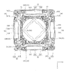
- FIG. 7 is a plan view of the main body of the lens driving device as viewed from the light receiving side in the optical axis direction.
- 8A and 8B are perspective views of the coil unit.
- 9A and 9B are perspective views of the coil unit.
- FIG. 10 is a plan view showing the arrangement of the base substrate.
- 11 is a wiring diagram showing a power supply line and a wiring line from the base board to the control IC.
- 12A and 12B are schematic views showing an example of the operation of the lens driving device.
- 13A and 13B are diagrams showing an automobile as a camera-mounted device for mounting an in-vehicle camera module.
- FIG. 1A and 1B are diagrams showing a smartphone M (camera-mounted device) equipped with the camera module A according to the embodiment of the present invention.
- FIG. 1A is a front view of the smartphone M
- FIG. 1B is a rear view of the smartphone M.
- the smartphone M is equipped with the camera module A as, for example, rear cameras OC1 and OC2.
- the camera module A has an AF function and an OIS function, automatically adjusts the focus when shooting a subject, and optically corrects the shake (vibration) that occurs during shooting to shoot an image without image blur. be able to.
- FIG. 2 is an external perspective view of the camera module A.
- FIG. 3 is a perspective view of the lens driving device 1.
- FIG. 3 shows a state in which the cover 60 is removed from the main bodies 10 to 50 of the lens driving device 1.
- an orthogonal coordinate system (X, Y, Z) will be used for description. Also in the figure described later, it is shown by a common Cartesian coordinate system (X, Y, Z).
- the camera module A is mounted so that the X direction is the vertical direction (or the horizontal direction), the Y direction is the horizontal direction (or the vertical direction), and the Z direction is the front-back direction when the smartphone M actually shoots.
- the Z direction is the optical axis direction
- the upper side in the figure is the optical axis direction light receiving side
- the lower side is the optical axis direction imaging side.
- the X and Y directions orthogonal to the Z axis are referred to as "optical axis orthogonal directions”
- the XY planes are referred to as "optical axis orthogonal planes”.
- the camera module A is an imaging unit (illustrated) that images a subject image formed by the lens driving device 1, the lens unit 2, and the lens unit 2 that realize the AF function and the OIS function. Omitted) etc.
- the lens driving device 1 is configured separately from the lens unit 2, and when performing automatic focusing or shake correction, an external force is applied to the liquid lens 71 (see FIG. 12A, etc.) of the lens unit 2 to obtain a focal length or light. Change the axis.
- the lens unit 2 has a liquid lens 71 (see FIG. 12A, etc.) in which a liquid is sealed in a transparent container.
- the liquid lens 71 is deformed by a force (compressive force or tensile force) in the optical axis direction, and the focal length and the optical axis change.
- the liquid lens 71 may be a gel-like lens as long as it is a lens that is deformed by an external force.
- a ring-shaped lens support member 72 (see FIG. 12A and the like) is adhered to the surface of the liquid lens 71 on the optical axis direction imaging side. Since the configuration of the liquid lens 71 is known, detailed description thereof will be omitted (see, for example, Patent Document 2).
- the cover 60 is a covered square cylinder having a rectangular shape (for example, a square shape) when viewed from the optical axis direction.
- the cover 60 has, for example, a two-stage diaphragm shape in which the central portion protrudes in a substantially cylindrical shape on the light receiving side in the optical axis direction.
- the lens unit 2 is arranged on the upper end surface 601 of the cover 60. Further, an adhesive injection port 603 is provided on the side surface 602 of the cover 60.
- the cover 60 is arranged so as to cover the main body portions 10 to 50, and is fixed, for example, by adhering the side surface 602 of the cover 60 and the yoke 33 (see FIG. 6).
- the imaging unit (not shown) is arranged on the optical axis direction imaging side of the lens driving device 1.
- the image pickup unit (not shown) has, for example, an image sensor substrate and an image pickup element mounted on the image sensor substrate.
- the image sensor is composed of, for example, a CCD (charge-coupled device) type image sensor, a CMOS (complementary metal oxide semiconductor) type image sensor, or the like.
- the image sensor captures a subject image formed by the lens unit 2.
- the lens driving device 1 is mounted on an image sensor substrate (not shown) and is mechanically and electrically connected.
- the control unit that controls the drive of the lens driving device 1 may be provided on the image sensor substrate, or may be provided on the camera-mounted device (smartphone M in the present embodiment) on which the camera module A is mounted. ..
- the energizing current in the coil 31 is controlled by the control signal from the control unit.
- FIGS. 4 to 6 are exploded perspective views of the main bodies 10 to 50 of the lens driving device 1.
- FIG. 5 shows a state in which the movable portion 10 and the support portion 40 in FIG. 4 are disassembled.
- FIG. 6 shows a state in which the fixing portion 20 in FIG. 4 is disassembled.
- FIG. 7 is a plan view of the main body portions 10 to 50 of the lens driving device 1 as viewed from the light receiving side in the optical axis direction.
- the lens driving device 1 includes a movable portion 10, a fixing portion 20, a driving portion 30, a supporting portion 40, a lens deforming portion 50, and the like.
- the movable portion 10 is a portion that moves in the optical axis direction during automatic focusing and runout correction.
- the fixed portion 20 is a portion that supports the movable portion 10 via the support portion 40.
- the movable portion 10 is arranged radially apart from the fixed portion 20, and is connected to the fixed portion 20 by the support portion 40.
- the drive unit 30 is composed of a voice coil motor including a coil 31 and a magnet 32.
- the coil 31 is arranged in the movable portion 10 and the magnet 32 is arranged in the fixed portion 20. That is, the moving coil system is adopted for the lens driving device 1. Compared with the moving magnet method in which the magnet 32 is arranged on the movable portion 10, the movable portion 10 is lighter and the amount of movement of the movable portion 10 is larger even if the driving force (Lorentz force generated in the coil 31) is the same (). Since the pressure applied to the liquid lens 71 increases), power saving can be achieved.
- the movable portion 10 is composed of first to fourth coil units 10A to 10D (movable units) arranged so as to have a rectangular shape in a plan view seen from the optical axis direction. Specifically, the first and second coil units 10A and 10B are arranged so as to face each other in the X direction, and the third and fourth coil units 10C and 10D are arranged so as to face each other in the Y direction. ..
- the first to fourth coil units 10A to 10D each have a coil substrate holder 11, a coil substrate 12, and a control IC 13 (see FIG. 8A and the like).
- 9A and 9B show a state in which FIGS. 8A and 8B are rotated by 180 ° around the Z axis.
- the coil board holder 11 is a member that holds the coil board 12.
- the coil board holder 11 holds an upper spring fixing portion 111 to which the upper elastic support member 41 is attached, a lower spring fixing portion 112 to which the lower elastic support member 42 is attached, an IC accommodating portion 113 accommodating the control IC 13, and the coil substrate 12. It has a substrate holding portion 114, a connecting member fixing portion 115 to which the lens deforming portion 50 is attached, and a base engaging portion 116 that engages with the base 21.
- the coil board 12 is a printed wiring board having a substantially rectangular shape, and is composed of, for example, a multilayer printed wiring board in which a plurality of unit layers composed of a conductor layer and an insulating layer (not shown) are laminated.
- the coil board 12 has a coil 31, a power supply terminal 14, a signal terminal 15, and wiring (not shown).
- the control IC 13 is mounted on the coil board 12.
- a conductor pattern including the coil 31, the power supply terminal 14, the signal terminal 15, and the wiring is integrally formed on the coil substrate 12.
- the wiring includes a power supply line connecting the power supply terminal 14 and the control IC 13, and a signal line connecting the signal terminal 15 and the control IC 13.
- the power supply terminal 14 is soldered to the upper elastic support member 41 and physically and electrically connected.
- the signal terminal 15 is soldered to the lower elastic support member 42 and physically and electrically connected.
- the coil substrate 12 is fitted into the coil substrate holder 11 so that both end portions 121 in the longitudinal direction of the coil substrate 12 engage with the substrate holding portion 114, and is fixed by adhesion.
- the control IC 13 is housed in the IC accommodating portion 113 of the coil substrate holder 11.
- control IC 13 has a built-in Hall element (not shown) that detects a change in the magnetic field by utilizing the Hall effect.
- Hall element When the coil units 10A to 10D move in the optical axis direction, the magnetic field generated by the magnets 32A to 32D changes. By detecting this change in the magnetic field with the Hall element, the positions of the coil units 10A to 10D in the optical axis direction are detected.
- Hall output By designing the layout of the Hall element and the magnets 32A to 32D so that the magnetic flux proportional to the movement amount of the coil units 10A to 10D intersects the detection surface of the Hall element, it is proportional to the movement amount of the coil units 10A to 10D. Hall output can be obtained.
- a magnet for position detection may be arranged on the fixing portion 20.
- the control IC 13 controls the energizing currents of the corresponding coils 31A to 31D based on the detection result (Hall output) by the built-in Hall element and the control signal received via the upper elastic support member 41.
- the power supply terminal 14 may be connected to the lower elastic support member 42, and the signal terminal 15 may be connected to the upper elastic support member 41.
- coils 31 arranged on the coil substrate 12 of the first to fourth coil units 10A to 10D are distinguished, they are referred to as "coils 31A to 31D".
- magnets 32 and the yoke 33 corresponding to the coils 31A to 31D are referred to as "magnets 32A to 32D” and "yoke 33A to 33D".
- the drive unit 30 has a coil 31, a magnet 32, and a yoke 33.
- the coil 31 is an air-core coil that is energized during automatic focusing and runout correction, and is formed on the coil substrate 12.
- the coil 31 is formed flat, for example, so that the coil surface is parallel to the optical axis, that is, the XZ surface or the YZ surface is the coil surface. Both ends of the coil 31 are connected to the power supply terminal 14 of the control IC 13, respectively.
- the magnet 32 is attached to the magnet fixing portion 211 of the base 21 at a distance from the coil 31 in the radial direction, and is fixed by adhesion, for example.
- the magnet 32 is magnetized in the optical axis direction and is arranged so that the magnetic flux crosses the two long sides of the coil 31 in opposite directions. As a result, when the coil 31 is energized, Lorentz forces in the same direction in the optical axis direction are generated on the two long sides.
- the voice coil motor is composed of the coil 31 and the magnet 32.
- the yoke 33 is formed of a magnetic material such as an SPC material, and is fixed to the outside of the magnet 32 in the radial direction, for example, by adhesion. In the magnetic circuit formed by the yoke 33 and the magnet 32, the magnetic flux efficiently intersects the coil 31, so that the driving efficiency is improved.
- the support portion 40 includes an upper elastic support member 41 (first elastic support member) that supports the movable portion 10 on the optical axis direction light receiving side (upper side) with respect to the fixed portion 20, and an optical axis direction imaging side (lower side). ) Includes a lower elastic support member 42 (second elastic support member).
- the upper elastic support member 41 and the lower elastic support member 42 are made of, for example, titanium copper, nickel copper, stainless steel, or the like.
- the upper elastic support member 41 is composed of upper springs 41A to 41D having the same structure.
- the upper springs 41A to 41D are arranged on the coil units 10A to 10B and the upper part of the base 21 so as not to come into contact with each other.
- the upper springs 41A to 41D are formed, for example, by etching a single sheet metal.
- the upper springs 41A to 41D each have a base fixing portion 411 fixed to the base 21, a holder fixing portion 412 fixed to the coil board holder 11, and an arm portion 413 connecting the base fixing portion 411 and the holder fixing portion 412, respectively.
- Two arm portions 413 extend from the base fixing portion 411, and a holder fixing portion 412 is arranged at the other end of the arm portion 413.
- the arm portion 413 is formed to be curved, and elastically deforms when the movable portion 10 moves in the optical axis direction.
- the upper springs 41A to 41D each have a jumper wire connecting portion 414 connected to the jumper wires 43A to 43D.
- the jumper wire connecting portion 414 extends radially inward from the base fixing portion 411 and is arranged.
- the upper springs 41A to 41D function as a power supply line together with the jumper wires 43A to 43D.
- the lower elastic support member 42 has the same configuration as the upper elastic support member 41. That is, the lower elastic support member 42 is composed of lower springs 42A to 42D having the same structure.
- the lower springs 42A to 42D are arranged below the coil units 10A to 10B and the base 21 so as not to come into contact with each other.
- the lower springs 42A to 42D are formed, for example, by etching a single sheet metal.
- the lower springs 42A to 42D each have a base fixing portion 421 fixed to the base 21, a holder fixing portion 422 fixed to the coil board holder 11, and an arm portion 423 connecting the base fixing portion 421 and the holder fixing portion 422, respectively.
- Two arm portions 423 extend from the base fixing portion 421, and a holder fixing portion 422 is arranged at the other end of the arm portion 423.
- the arm portion 423 is formed to be curved, and elastically deforms when the movable portion 10 moves in the optical axis direction.
- the lower springs 42A to 42D each have a jumper wire connecting portion 424 connected to the jumper wires 44A to 44D.
- the jumper wire connecting portion 424 extends radially outward from the base fixing portion 421.
- the lower springs 42A to 42D function as a signal line together with the jumper wires 44A to 44D.
- a damper material 61 (see FIG. 7) is appropriately arranged on the arm portions 413 of the upper springs 41A to 41D and the arm portions 423 of the lower springs 42A to 42D.
- the damper material 61 is arranged in the folded and adjacent portions (the portion D surrounded by the broken line in FIG. 5).
- the damper material 61 can be easily applied using, for example, a dispenser.
- an ultraviolet curable silicone gel can be applied.
- the lens deforming portion 50 has a lens contact member 51 and a connecting member 52.
- the lens contact member 51 has, for example, a rectangular ring shape and abuts on the liquid lens 71.
- the lens contact member 51 is fixed to the lens support member 72 by adhesion and indirectly contacts the liquid lens 71.
- the connecting member 52 is provided corresponding to the coil units 10A to 10D, and connects the lens contact member 51 and each coil unit 10A to 10D (coil substrate holder 11).
- one end of the connecting member 52 is fixed to the four corners of the lens contact member 51, and the other end is fixed to the connecting member fixing portion 115 of the coil substrate holder 11.
- the lens contact member 51 presses the liquid lens 71 uniformly or in an inclined state, for example, as the coil units 10A to 10D move toward the light receiving side in the optical axis direction.
- the posture of the lens contact member 51 is adjusted by the amount of movement of the coil units 10A to 10D. Specifically, at the time of automatic focusing, the amount of movement of the coil units 10A to 10D is controlled to be the same, and the lens contact member 51 uniformly presses the liquid lens 71. As a result, the focal length changes and automatic focusing is performed. Further, at the time of runout correction, the movement amounts of the coil units 10A to 10D are controlled so as to be different, and the lens contact member 51 presses the liquid lens 71 in an inclined state. As a result, the optical axis of the liquid lens 71 is tilted, and runout correction is performed.
- Each of the four connecting members 52 is formed in a zigzag shape symmetrically with respect to the optical axis direction.
- the shape of the lens contact member 51 may be any shape as long as the liquid lens 71 can be pressed uniformly or in an inclined state, and may be, for example, a circular ring shape. Further, the shape of the connecting member 52 may be any shape as long as it can absorb the twist of the lens contact member 51 at the time of runout correction.
- the fixing portion 20 is composed of a base 21 and a base substrate 22.
- the base 21 is a member having a rectangular shape in a plan view, and has an opening 21a in a region corresponding to the liquid lens 71. Further, the base 21 has a magnet fixing portion 211, a coil unit holding portion 212, an upper spring fixing portion 213, and a lower spring fixing portion 214. These are formed so as to project from the base surface toward the light receiving side in the optical axis direction, and function as ribs for reinforcing the base 21.
- Two magnet fixing portions 211 are provided on two sides along the X direction and two sides along the Y direction of the peripheral peripheral portion of the base, and the magnet 32 and the yoke 33 are fixed between them.
- the coil unit holding portions 212 are provided at four locations on the peripheral edge of the opening 21a, and the coil units 10A to 10D are arranged so as to be movable in the optical axis direction between the two adjacent coil unit holding portions 212.
- the upper spring fixing portions 213 are provided at the four corners of the base, and the base fixing portions 411 of the upper elastic support member 41 are fixed.
- the lower spring fixing portions 214 are provided at the four corners of the base, and the base fixing portions 421 of the lower elastic support member 42 are fixed.
- the upper spring fixing portion 213 and the lower spring fixing portion 214 are integrally formed.
- the base board 22 is a printed wiring board having a main board part 221, an external terminal part 222, an upper spring connection part 223, a lower spring connection part 224, and wiring (not shown) (see FIG. 10).
- the main substrate portion 221 is formed so as to cover substantially the entire surface of the base 21.
- the external terminal portion 222 extends from one side of the main board portion 221 and is bent and arranged along one side surface of the base 21.
- the upper spring connecting portion 223 is arranged so as to be located inside the upper spring fixing portion 213 of the base 21.
- the lower spring connecting portion 224 is arranged so as to wrap around the upper spring fixing portion 213 and the lower spring fixing portion 214 of the base 21 and extend to the four corners of the base 21 and to be located outside the lower spring fixing portion 214.
- the wiring includes a power supply line and a signal line from the external terminal portion 222.
- the conductor pattern of the power feeding line is exposed from the upper spring connecting portion 223 and is electrically connected to the upper springs 41A to 41D via the jumper wires 43A to 43D.
- the conductor pattern of the signal line is exposed from the lower spring connecting portion 224 and is electrically connected to the lower springs 42A to 42D via the jumper wires 44A to 44D.
- wiring or the like may be integrally formed in the base 21 by insert molding.
- FIG. 11 is a wiring diagram showing an example of a power supply line and a wiring line from the base board 22 (the drive unit that performs drive control) to the control IC 13.
- I2C Inter-Integrated Circuit
- the power supply terminal VDD (plus power supply) of the base substrate 22 is controlled by the control ICs 13A and 13D (control IC13 of the coil units 10A and 10D) via the jumper wire 43A and the upper spring 41A.
- the power supply terminal VSS (minus power supply) of the base board 22 is connected to the power supply terminal VSS of the control ICs 13A and 13C via the jumper wire 43C and the upper spring 41C, and of the control ICs 13B and 13D via the jumper wire 43D and the upper spring 41D. It is connected to the power supply terminal VSS.
- the signal terminal SDA (data signal) of the base board 22 is connected to the signal terminals SDA of the control ICs 13A and 13D via the jumper wire 44A and the lower spring 42A, and of the control ICs 13B and 13C via the jumper wire 44B and the lower spring 42B. It is connected to the signal terminal SDA.
- the signal terminal SCL (clock signal) of the base board 22 is connected to the signal terminals SCL of the control ICs 13A and 13C via the jumper wire 44C and the lower spring 42C, and of the control ICs 13B and 13D via the jumper wire 44D and the lower spring 42D. It is connected to the signal terminal SCL.
- the upper elastic support member 41 (first elastic support member) connects the power supply terminals VDD and VSS of the adjacent coil units 10A to 10D (movable unit) to each other, and the lower elastic support member 42 (first elastic support member 42).
- the elastic support member (2) connects the signal terminals SDA and SCL of the adjacent coil units 10A to 10D (movable unit) to each other.
- the upper elastic support member 41 and the lower elastic support member 42 are wired to the base substrate 22 by jumper wires 43A to 43D and 44A to 44D extending from the fixing portion 20 (base substrate 22) to the light receiving side in the optical axis direction. Is electrically connected to.
- FIG. 12A and 12B are schematic views showing an example of the operation of the lens driving device.
- FIG. 12A shows a state when automatic focusing is performed
- FIG. 12B shows a state when runout correction is performed.
- the coils 31 arranged in the coil units 10A to 10D are energized.
- a Lorentz force is generated in the coil 31 due to the interaction between the magnetic field of the magnet 32 and the current flowing through the coil 31.
- the direction of the Lorentz force is a direction (Z direction) orthogonal to the direction of the magnetic field and the direction of the current flowing through the coil 31. Since the magnet 32 is fixed, a reaction force acts on the coil 31. This reaction force becomes the driving force of the voice coil motor, and the coil units 10A to 10D in which the coil 31 is arranged move in the optical axis direction.
- the energizing currents of the coils 31A to 31D arranged in the coil units 10A to 10D can be independently controlled by the corresponding control ICs 13A to 13D.
- the energizing currents in the coils 31A to 31D are controlled to the same value.
- the lens deformed portion 50 is uniformly pressed against the liquid lens 71 (for example, pressure P).
- the curvature (lens thickness) of the liquid lens 71 changes uniformly, and the focal length changes (see FIG. 12A).
- focusing can be performed by controlling the energizing currents of the coils 31A to 31D and adjusting the amount of movement of the lens deforming portion 50.
- the energizing currents in the coils 31A to 31D are controlled to different values. For example, when the coil units 10A to 10D move to the light receiving side in the optical axis direction with different behaviors, the lens deformed portion 50 is pressed against the liquid lens 71 in an inclined state (for example, pressures P1, P2 (> P1)). ). As a result, the optical axis AX of the liquid lens 71 changes (see FIG. 12B). Therefore, the runout correction can be performed by controlling the energizing currents of the coils 31A to 31D and adjusting the posture of the lens deforming portion 50.
- the focal length of the liquid lens 71 is such that the lens contact member 51 pulls the liquid lens 71 uniformly or in an inclined state as the coil units 10A to 10D move toward the image forming side in the optical axis direction.
- the distance or optical axis may be adjusted. Further, when performing runout correction, the opposing coil units 10A and 10B, 10C and 10D may be moved in opposite directions to each other.
- the lens driving device 1 is configured separately from the lens unit 2 having the liquid lens 71, and applies an external force to the liquid lens 71 to change the focal length and the optical axis of the liquid lens 71.
- the lens driving device 1 includes a fixed portion 20, a movable portion 10 arranged apart from the fixed portion 20, a support portion 40 that supports the movable portion 10 with respect to the fixed portion 20, a coil 31, and a magnet 32. It is composed of a voice coil motor, is connected to a drive unit 30 that moves the movable portion 10 in the optical axis direction with respect to the fixed portion 20, and is connected to the movable portion 10, and moves in the optical axis direction to the liquid lens 71 as the movable portion 10 moves.
- a lens deforming portion 50 for applying a force is provided.
- the movable portion 10 has a plurality of coil units 10A to 10D (movable units).
- the coil 31 is arranged in a plurality of coil units 10A to 10D, and the magnet 32 is arranged in a position corresponding to the coil units 10A to 10D in the fixing portion 20.
- the drive unit 30 independently drives the plurality of coil units 10A to 10D so that the curvature of the liquid lens changes or the optical axis of the liquid lens changes.
- the lens drive device 1 is configured separately from the lens unit 2, it is excellent in versatility, and since the drive unit for automatic focusing and runout correction is shared, it is downsized and lightweight. Can be planned.
- the coil 31 is arranged in the movable portion 10 (coil units 10A to 10D) and the magnet 32 is arranged in the fixed portion 20 (base 21), but the magnet 32 is arranged in the movable portion 10.
- the coil 31 may be arranged in the movable portion 10.
- the base substrate 22, the upper elastic support member 41 and the lower elastic support member 42 are electrically connected to the base 21 via jumper wires 43A to 43D and 44A to 44D.
- Wiring (not shown) may be three-dimensionally formed by insert molding so that the wiring and the upper elastic support member 41 and the lower elastic support member 42 are directly connected.
- a smartphone M which is a mobile terminal with a camera
- the present invention processes the camera module and the image information obtained by the camera module. It can be applied to a camera-mounted device having an image processing unit.
- Camera-mounted devices include information devices and transportation devices.
- the information device includes, for example, a mobile phone with a camera, a notebook computer, a tablet terminal, a portable game machine, a web camera, and an in-vehicle device with a camera (for example, a back monitor device and a drive recorder device).
- transportation equipment includes, for example, automobiles.
- FIGS. 13A and 13B are diagrams showing an automobile V as a camera-mounted device on which an in-vehicle camera module VC (Vehicle Camera) is mounted.
- 13A is a front view of the automobile V
- FIG. 13B is a rear perspective view of the automobile V.
- the automobile V is equipped with the camera module A described in the embodiment as the in-vehicle camera module VC.
- the vehicle-mounted camera module VC may be attached to the windshield toward the front or attached to the rear gate toward the rear, for example.
- This in-vehicle camera module VC is used for a back monitor, a drive recorder, a collision avoidance control, an automatic driving control, and the like.
- Lens drive device Lens unit 10 Movable part 10A-10D Coil unit (movable unit) 11 Coil board holder 12 Coil board 13 Control IC 20 Fixed part 21 Base 22 Base board 30 Drive part 31, 31A to 31D Coil 32, 32A to 32D Magnet 33, 33A to 33D York 40 Support part 41 Upper elastic support member (first elastic support member) 42 Lower elastic support member (second elastic support member) 50 Lens deformation part 51 Lens contact member 52 Connecting member 60 Cover 71 Liquid lens 72 Lens support member M Smartphone A Camera module
Landscapes
- Physics & Mathematics (AREA)
- General Physics & Mathematics (AREA)
- Optics & Photonics (AREA)
- Engineering & Computer Science (AREA)
- Electromagnetism (AREA)
- Combustion & Propulsion (AREA)
- Chemical & Material Sciences (AREA)
- Power Engineering (AREA)
- Multimedia (AREA)
- Signal Processing (AREA)
- Adjustment Of Camera Lenses (AREA)
- Lens Barrels (AREA)
- Studio Devices (AREA)
- Camera Bodies And Camera Details Or Accessories (AREA)
Priority Applications (3)
| Application Number | Priority Date | Filing Date | Title |
|---|---|---|---|
| CN202080036741.9A CN113841070B (zh) | 2019-05-22 | 2020-05-22 | 透镜驱动装置、摄像机模块及摄像机搭载装置 |
| US17/595,524 US12111460B2 (en) | 2019-05-22 | 2020-05-22 | Lens driving device, camera module, and camera-mounted apparatus |
| KR1020217035873A KR102788648B1 (ko) | 2019-05-22 | 2020-05-22 | 렌즈 구동장치, 카메라 모듈, 및 카메라 탑재 장치 |
Applications Claiming Priority (2)
| Application Number | Priority Date | Filing Date | Title |
|---|---|---|---|
| JP2019096197A JP7295403B2 (ja) | 2019-05-22 | 2019-05-22 | レンズ駆動装置、カメラモジュール、及びカメラ搭載装置 |
| JP2019-096197 | 2019-05-22 |
Publications (1)
| Publication Number | Publication Date |
|---|---|
| WO2020235667A1 true WO2020235667A1 (ja) | 2020-11-26 |
Family
ID=73454520
Family Applications (1)
| Application Number | Title | Priority Date | Filing Date |
|---|---|---|---|
| PCT/JP2020/020217 Ceased WO2020235667A1 (ja) | 2019-05-22 | 2020-05-22 | レンズ駆動装置、カメラモジュール、及びカメラ搭載装置 |
Country Status (5)
| Country | Link |
|---|---|
| US (1) | US12111460B2 (https=) |
| JP (1) | JP7295403B2 (https=) |
| KR (1) | KR102788648B1 (https=) |
| CN (1) | CN113841070B (https=) |
| WO (1) | WO2020235667A1 (https=) |
Cited By (3)
| Publication number | Priority date | Publication date | Assignee | Title |
|---|---|---|---|---|
| CN112616000A (zh) * | 2020-12-31 | 2021-04-06 | 南昌欧菲光电技术有限公司 | 驱动装置、摄像模组及电子设备 |
| CN113709349A (zh) * | 2021-09-02 | 2021-11-26 | 维沃移动通信有限公司 | 摄像组件和电子设备 |
| JP2022132017A (ja) * | 2021-02-26 | 2022-09-07 | 北京小米移動軟件有限公司 | カメラモジュール及び電子機器 |
Families Citing this family (10)
| Publication number | Priority date | Publication date | Assignee | Title |
|---|---|---|---|---|
| CN111736243B (zh) * | 2019-02-28 | 2025-03-11 | 华为技术有限公司 | 驱动液体镜头的音圈马达及具有音圈马达的镜头组件 |
| CN113311642B (zh) * | 2021-05-31 | 2022-11-18 | 新思考电机有限公司 | 透镜驱动装置、摄像装置及电子设备 |
| CN115484358B (zh) * | 2021-05-31 | 2025-09-19 | 北京小米移动软件有限公司 | 致动器、摄像头模组和电子设备 |
| CN115643481B (zh) * | 2021-07-20 | 2025-02-18 | 北京小米移动软件有限公司 | 致动器、摄像头模组和电子设备 |
| CN115694089A (zh) * | 2021-07-27 | 2023-02-03 | 北京小米移动软件有限公司 | 致动器、摄像头模组和电子设备 |
| CN113691714B (zh) * | 2021-08-24 | 2023-07-25 | 维沃移动通信(杭州)有限公司 | 电子设备 |
| KR20230157134A (ko) * | 2022-05-09 | 2023-11-16 | 엘지이노텍 주식회사 | 렌즈 구동 장치, 및 이를 포함하는 카메라 모듈과 광학 기기 |
| US12477224B2 (en) * | 2022-06-10 | 2025-11-18 | Mitsumi Electric Co., Ltd. | Optical element driving apparatus, camera module and camera-equipped apparatus |
| JP7410443B2 (ja) * | 2022-06-10 | 2024-01-10 | ミツミ電機株式会社 | 光学素子駆動装置、カメラモジュール及びカメラ搭載装置 |
| KR102879981B1 (ko) * | 2022-12-29 | 2025-10-31 | 삼성전기주식회사 | 렌즈 구동 장치 및 렌즈 구동 장치의 제조 방법 |
Citations (6)
| Publication number | Priority date | Publication date | Assignee | Title |
|---|---|---|---|---|
| JP2015114615A (ja) * | 2013-12-13 | 2015-06-22 | 日本電産サンキョー株式会社 | 撮影用光学装置および撮影用光学装置の制御方法 |
| JP2017003956A (ja) * | 2015-06-12 | 2017-01-05 | 日本電産コパル株式会社 | レンズ駆動装置、ユニット及びカメラ |
| JP6498188B2 (ja) * | 2013-10-08 | 2019-04-10 | オプトチューン コンシューマー アーゲー | 調整可能なレンズ装置 |
| US20190129132A1 (en) * | 2017-10-30 | 2019-05-02 | Tdk Taiwan Corp. | Optical driving mechanism |
| JP2019139223A (ja) * | 2018-01-25 | 2019-08-22 | 台湾東電化股▲ふん▼有限公司 | 光学システム |
| JP2020112793A (ja) * | 2018-12-27 | 2020-07-27 | 台湾東電化股▲ふん▼有限公司 | 光学システム |
Family Cites Families (7)
| Publication number | Priority date | Publication date | Assignee | Title |
|---|---|---|---|---|
| JP2008058391A (ja) * | 2006-08-29 | 2008-03-13 | Samsung Yokohama Research Institute Co Ltd | 撮像レンズユニットおよび撮像装置 |
| CN101819314B (zh) * | 2009-12-23 | 2012-12-12 | 香港应用科技研究院有限公司 | 透镜控制装置 |
| JP5849830B2 (ja) | 2012-03-30 | 2016-02-03 | ミツミ電機株式会社 | レンズホルダ駆動装置、カメラモジュール、およびカメラ付き携帯端末 |
| CN104597534A (zh) * | 2015-02-16 | 2015-05-06 | 杭州清渠科技有限公司 | 一种可调控复眼透镜阵列及其制作方法 |
| JP7123137B2 (ja) * | 2017-11-22 | 2022-08-22 | オプトチューン コンシューマー アーゲー | オートフォーカス及び光学式手ぶれ補正機構を備える光学デバイス、特にカメラ |
| CN109597148A (zh) * | 2018-10-24 | 2019-04-09 | 东莞佩斯讯光电技术有限公司 | 一种驱动液态镜头的马达及镜头组 |
| CN111736243B (zh) * | 2019-02-28 | 2025-03-11 | 华为技术有限公司 | 驱动液体镜头的音圈马达及具有音圈马达的镜头组件 |
-
2019
- 2019-05-22 JP JP2019096197A patent/JP7295403B2/ja active Active
-
2020
- 2020-05-22 CN CN202080036741.9A patent/CN113841070B/zh active Active
- 2020-05-22 US US17/595,524 patent/US12111460B2/en active Active
- 2020-05-22 WO PCT/JP2020/020217 patent/WO2020235667A1/ja not_active Ceased
- 2020-05-22 KR KR1020217035873A patent/KR102788648B1/ko active Active
Patent Citations (6)
| Publication number | Priority date | Publication date | Assignee | Title |
|---|---|---|---|---|
| JP6498188B2 (ja) * | 2013-10-08 | 2019-04-10 | オプトチューン コンシューマー アーゲー | 調整可能なレンズ装置 |
| JP2015114615A (ja) * | 2013-12-13 | 2015-06-22 | 日本電産サンキョー株式会社 | 撮影用光学装置および撮影用光学装置の制御方法 |
| JP2017003956A (ja) * | 2015-06-12 | 2017-01-05 | 日本電産コパル株式会社 | レンズ駆動装置、ユニット及びカメラ |
| US20190129132A1 (en) * | 2017-10-30 | 2019-05-02 | Tdk Taiwan Corp. | Optical driving mechanism |
| JP2019139223A (ja) * | 2018-01-25 | 2019-08-22 | 台湾東電化股▲ふん▼有限公司 | 光学システム |
| JP2020112793A (ja) * | 2018-12-27 | 2020-07-27 | 台湾東電化股▲ふん▼有限公司 | 光学システム |
Cited By (5)
| Publication number | Priority date | Publication date | Assignee | Title |
|---|---|---|---|---|
| CN112616000A (zh) * | 2020-12-31 | 2021-04-06 | 南昌欧菲光电技术有限公司 | 驱动装置、摄像模组及电子设备 |
| JP2022132017A (ja) * | 2021-02-26 | 2022-09-07 | 北京小米移動軟件有限公司 | カメラモジュール及び電子機器 |
| JP7606420B2 (ja) | 2021-02-26 | 2024-12-25 | 北京小米移動軟件有限公司 | カメラモジュール及び電子機器 |
| US12204117B2 (en) | 2021-02-26 | 2025-01-21 | Beijing Xiaomi Mobile Software Co., Ltd. | Camera unit and electronic device |
| CN113709349A (zh) * | 2021-09-02 | 2021-11-26 | 维沃移动通信有限公司 | 摄像组件和电子设备 |
Also Published As
| Publication number | Publication date |
|---|---|
| JP7295403B2 (ja) | 2023-06-21 |
| KR20220008261A (ko) | 2022-01-20 |
| CN113841070B (zh) | 2024-06-28 |
| US12111460B2 (en) | 2024-10-08 |
| US20220206287A1 (en) | 2022-06-30 |
| CN113841070A (zh) | 2021-12-24 |
| KR102788648B1 (ko) | 2025-03-28 |
| JP2020190646A (ja) | 2020-11-26 |
Similar Documents
| Publication | Publication Date | Title |
|---|---|---|
| WO2020235667A1 (ja) | レンズ駆動装置、カメラモジュール、及びカメラ搭載装置 | |
| JP6892611B2 (ja) | レンズ駆動装置、カメラモジュール、及びカメラ搭載装置 | |
| JP7157314B2 (ja) | カメラモジュール、及びカメラ搭載装置 | |
| CN107111208B (zh) | 致动器、摄像机模块及摄像机搭载装置 | |
| CN113168074B (zh) | 透镜驱动装置、摄像机模块及摄像机搭载装置 | |
| JP6565340B2 (ja) | レンズ駆動装置、カメラモジュール、及びカメラ搭載装置 | |
| WO2016194345A1 (ja) | アクチュエーター、カメラモジュール及びカメラ搭載装置 | |
| WO2018021489A1 (ja) | レンズ駆動装置、カメラモジュール、及びカメラ搭載装置 | |
| WO2018021479A1 (ja) | アクチュエーター、カメラモジュール及びカメラ搭載装置 | |
| TW201626027A (zh) | 鏡頭驅動裝置、相機模組以及相機搭載裝置 | |
| JP6492976B2 (ja) | アクチュエーター、カメラモジュール及びカメラ搭載装置 | |
| JP7096484B2 (ja) | レンズ駆動装置、カメラモジュール、及びカメラ搭載装置 | |
| WO2021117374A1 (ja) | レンズ駆動装置、カメラモジュール、及びカメラ搭載装置 | |
| US12276811B2 (en) | Sensor shifting actuator and camera module including sensor shifting actuator | |
| JP7231820B2 (ja) | レンズ駆動装置、カメラモジュール、及びカメラ搭載装置 | |
| JP7376782B2 (ja) | レンズ駆動装置、カメラモジュール及びカメラ搭載装置 | |
| CN117872559A (zh) | 透镜驱动装置、摄像机模块及摄像机搭载装置 | |
| CN118330836B (zh) | 光学元件驱动装置、照相机模块以及照相机搭载装置 | |
| JP2023051206A (ja) | 光学素子駆動装置、カメラモジュール及びカメラ搭載装置 | |
| JP2024156347A (ja) | 光学素子駆動装置、カメラモジュール及びカメラ搭載装置 | |
| CN117805998A (zh) | 光学元件驱动装置、照相机模块以及照相机搭载装置 | |
| JP2023032341A (ja) | 光学素子駆動装置、カメラモジュール及びカメラ搭載装置 |
Legal Events
| Date | Code | Title | Description |
|---|---|---|---|
| 121 | Ep: the epo has been informed by wipo that ep was designated in this application |
Ref document number: 20810427 Country of ref document: EP Kind code of ref document: A1 |
|
| NENP | Non-entry into the national phase |
Ref country code: DE |
|
| 122 | Ep: pct application non-entry in european phase |
Ref document number: 20810427 Country of ref document: EP Kind code of ref document: A1 |