WO2020235145A1 - 紫外線用光学系及び配光測定装置 - Google Patents
紫外線用光学系及び配光測定装置 Download PDFInfo
- Publication number
- WO2020235145A1 WO2020235145A1 PCT/JP2020/003948 JP2020003948W WO2020235145A1 WO 2020235145 A1 WO2020235145 A1 WO 2020235145A1 JP 2020003948 W JP2020003948 W JP 2020003948W WO 2020235145 A1 WO2020235145 A1 WO 2020235145A1
- Authority
- WO
- WIPO (PCT)
- Prior art keywords
- ultraviolet
- optical system
- sensor
- light
- ultraviolet light
- Prior art date
- Legal status (The legal status is an assumption and is not a legal conclusion. Google has not performed a legal analysis and makes no representation as to the accuracy of the status listed.)
- Ceased
Links
Images

Classifications
-
- G—PHYSICS
- G01—MEASURING; TESTING
- G01J—MEASUREMENT OF INTENSITY, VELOCITY, SPECTRAL CONTENT, POLARISATION, PHASE OR PULSE CHARACTERISTICS OF INFRARED, VISIBLE OR ULTRAVIOLET LIGHT; COLORIMETRY; RADIATION PYROMETRY
- G01J1/00—Photometry, e.g. photographic exposure meter
- G01J1/02—Details
- G01J1/04—Optical or mechanical part supplementary adjustable parts
- G01J1/0407—Optical elements not provided otherwise, e.g. manifolds, windows, holograms, gratings
- G01J1/0411—Optical elements not provided otherwise, e.g. manifolds, windows, holograms, gratings using focussing or collimating elements, i.e. lenses or mirrors; Aberration correction
-
- G—PHYSICS
- G01—MEASURING; TESTING
- G01J—MEASUREMENT OF INTENSITY, VELOCITY, SPECTRAL CONTENT, POLARISATION, PHASE OR PULSE CHARACTERISTICS OF INFRARED, VISIBLE OR ULTRAVIOLET LIGHT; COLORIMETRY; RADIATION PYROMETRY
- G01J1/00—Photometry, e.g. photographic exposure meter
-
- G—PHYSICS
- G01—MEASURING; TESTING
- G01J—MEASUREMENT OF INTENSITY, VELOCITY, SPECTRAL CONTENT, POLARISATION, PHASE OR PULSE CHARACTERISTICS OF INFRARED, VISIBLE OR ULTRAVIOLET LIGHT; COLORIMETRY; RADIATION PYROMETRY
- G01J1/00—Photometry, e.g. photographic exposure meter
- G01J1/42—Photometry, e.g. photographic exposure meter using electric radiation detectors
- G01J1/4228—Photometry, e.g. photographic exposure meter using electric radiation detectors arrangements with two or more detectors, e.g. for sensitivity compensation
-
- G—PHYSICS
- G01—MEASURING; TESTING
- G01J—MEASUREMENT OF INTENSITY, VELOCITY, SPECTRAL CONTENT, POLARISATION, PHASE OR PULSE CHARACTERISTICS OF INFRARED, VISIBLE OR ULTRAVIOLET LIGHT; COLORIMETRY; RADIATION PYROMETRY
- G01J1/00—Photometry, e.g. photographic exposure meter
- G01J1/42—Photometry, e.g. photographic exposure meter using electric radiation detectors
- G01J1/4257—Photometry, e.g. photographic exposure meter using electric radiation detectors applied to monitoring the characteristics of a beam, e.g. laser beam, headlamp beam
-
- G—PHYSICS
- G01—MEASURING; TESTING
- G01J—MEASUREMENT OF INTENSITY, VELOCITY, SPECTRAL CONTENT, POLARISATION, PHASE OR PULSE CHARACTERISTICS OF INFRARED, VISIBLE OR ULTRAVIOLET LIGHT; COLORIMETRY; RADIATION PYROMETRY
- G01J1/00—Photometry, e.g. photographic exposure meter
- G01J1/42—Photometry, e.g. photographic exposure meter using electric radiation detectors
- G01J1/429—Photometry, e.g. photographic exposure meter using electric radiation detectors applied to measurement of ultraviolet light
-
- G—PHYSICS
- G01—MEASURING; TESTING
- G01M—TESTING STATIC OR DYNAMIC BALANCE OF MACHINES OR STRUCTURES; TESTING OF STRUCTURES OR APPARATUS, NOT OTHERWISE PROVIDED FOR
- G01M11/00—Testing of optical apparatus; Testing structures by optical methods not otherwise provided for
-
- G—PHYSICS
- G02—OPTICS
- G02B—OPTICAL ELEMENTS, SYSTEMS OR APPARATUS
- G02B13/00—Optical objectives specially designed for the purposes specified below
- G02B13/14—Optical objectives specially designed for the purposes specified below for use with infrared or ultraviolet radiation
-
- H—ELECTRICITY
- H04—ELECTRIC COMMUNICATION TECHNIQUE
- H04N—PICTORIAL COMMUNICATION, e.g. TELEVISION
- H04N23/00—Cameras or camera modules comprising electronic image sensors; Control thereof
- H04N23/50—Constructional details
- H04N23/55—Optical parts specially adapted for electronic image sensors; Mounting thereof
Definitions
- the present invention relates to an optical system for ultraviolet rays and a light distribution measuring device.
- an optical system for ultraviolet rays that forms an image of ultraviolet light and the optical system for ultraviolet rays form an image of ultraviolet light at each angle from an ultraviolet light source. It relates to a light distribution measuring device that outputs light distribution characteristics.
- Non-Patent Document 1 proposes a method in which light from an angle from a light source is captured at once by an optical system, imaged on a two-dimensional sensor, and the light distribution characteristics are measured at once.
- LEDs light emission diodes
- their use scenes are increasing as ultraviolet light sources.
- ultraviolet light has a limited number of materials that can be transmitted, so an optical system for ultraviolet rays used for measuring the light distribution of an ultraviolet light source has not been put into practical use. That is, in the conventional optical configuration as proposed in Patent Document 1 and Non-Patent Document 1, the transmission loss of ultraviolet light is too large, and the light distribution of the ultraviolet light source cannot be measured with high accuracy.
- the present invention has been made in view of such a situation, and an object of the present invention is an ultraviolet optical system capable of capturing ultraviolet light for each angle from an ultraviolet light source at a time, and an ultraviolet light source using the optical system for ultraviolet rays. It is an object of the present invention to provide a light distribution measuring device capable of performing high-precision light distribution measurement at one time.
- the ultraviolet optical system of the present invention includes an objective lens group that captures ultraviolet light for each angle from an ultraviolet light source to form an intermediate image, and an imaging lens that reimages the intermediate image.
- An optical system for ultraviolet rays equipped with a group and The objective lens group and the imaging lens group are both characterized in that they do not have a bonding surface and are composed of only a single lens that transmits ultraviolet light having a wavelength of 300 nm or less.
- the light distribution measuring device of the present invention includes an optical system for ultraviolet rays of the present invention and a sensor that converts an optical image formed on a light receiving surface of the sensor into an electrical signal, and obtains a signal obtained by the sensor.
- a light distribution measuring device that outputs the light distribution of the ultraviolet light source by using the device.
- the ultraviolet optical system is located on the sensor light receiving surface so that the intermediate image is reimaged, and the sensor has a light receiving sensitivity of ultraviolet light having a wavelength of 300 nm or less.
- the angle from the ultraviolet light source since neither the objective lens group nor the imaging lens group has a joint surface and is composed of only a single lens that transmits ultraviolet light having a wavelength of 300 nm or less, the angle from the ultraviolet light source. It is possible to realize an optical system for ultraviolet rays that can capture each ultraviolet light at once. By using the ultraviolet optical system together with a sensor having a light receiving sensitivity of ultraviolet light having a wavelength of 300 nm or less in a light distribution measuring device, it is possible to perform high-precision light distribution measurement of an ultraviolet light source at a time.
- the optical block diagram of the 2nd Embodiment (Example 2). The schematic diagram which shows the surface reflection in the optical system for ultraviolet rays.
- the ultraviolet optical system according to the embodiment of the present invention includes an objective lens group that captures ultraviolet light for each angle from an ultraviolet light source to form an intermediate image, and an imaging lens group that reimages the intermediate image. It is configured with.
- the objective lens group and the imaging lens group both have no bonding surface and are composed of only a single lens that transmits ultraviolet light having a wavelength of 300 nm or less.
- the ultraviolet light source includes ultraviolet excitation for fluorescence emission lighting and fluorescence image display, ultraviolet sterilization, and the like.
- LED light sources for example, the diameter of the measurement area to be evaluated is 3 mm and the emission point size is 100 ⁇ m
- the measurement wavelength range can be expanded or changed from the visible light region to the ultraviolet region. It is requested.
- an optical material for visible light is used for the optical system for ultraviolet rays, most of the ultraviolet rays are absorbed and cannot be transmitted, and cannot reach the sensor. Even when an optical material for ultraviolet rays is used, the transmission loss is large as compared with the case of visible light. Therefore, it is important how to minimize the transmission loss in the optical system.
- the optical system for ultraviolet rays is composed of only a single lens that transmits ultraviolet light having a wavelength of 300 nm or less, transmission loss in the optical material is suppressed, and the transmission efficiency of the optical system is improved. Therefore, it is possible to minimize the transmission loss in the optical system and capture the ultraviolet light for each angle from the ultraviolet light source at one time.
- the ultraviolet optical system having the above-mentioned characteristic configuration in the light distribution measuring device together with the sensor having the light receiving sensitivity of ultraviolet light having a wavelength of 300 nm or less, high-precision light distribution measurement of the ultraviolet light source can be performed at once. Is possible.
- the light distribution of the ultraviolet light source indicates in which direction (angle) the ultraviolet rays are radiated from the ultraviolet light source and at what intensity by the change or distribution of the luminous intensity with respect to the angle.
- the transmittance for ultraviolet light having a wavelength of 300 nm is preferably 80% or more, and more preferably 97% or more.
- the optical material for the single lens include CaF 2 , BaF 2 , and SiO 2 .
- the refractive index of these optical materials at a wavelength of 300 nm is about 1.5.
- the difference between the minimum inter-plane distance and the maximum inter-plane distance between all lens surfaces is equal to or greater than the working distance.
- the ultraviolet light reflected between the lens surfaces the one reflected at an angle with a large amount of light may greatly affect the accuracy of the light distribution measurement. It is possible to avoid the effect by sufficiently changing the surface spacing between the on-axis and off-axis between all the lens surfaces, and the longer the optical total length of the ultraviolet optical system, the greater the effect of suppressing the effect. Become.
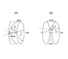
- FIG. 3 shows a specific example of inter-plane reflection in the ultraviolet optical system.
- the minimum surface distance tmin is formed at the end of the lens surface, and the distance between the lens surfaces is AX.
- the maximum inter-lens distance tmax is configured by.
- the minimum inter-plane distance tmin is configured on the optical axis AX of the lens surface, and the end portion of the lens surface is formed.
- the maximum inter-lens distance tmax is configured by.
- the normal light L1 is transmitted through the lens surface, and the unnecessary light L2 is reflected by the lens surface and proceeds to the peripheral portion of the lens. That is, the smaller the inter-plane distance difference tmax-tmin, the more likely it is that unnecessary light L2 toward the sensor side is generated due to reflection on the lens surfaces that are inclined to each other. From the relationship between the maximum measurement angle and the working distance in the light distribution measurement, if the inter-plane distance difference tmax-tmin is set to the working distance or more, the unnecessary light L2 reaching the sensor is reduced and the detection error due to the unnecessary light L2 is effective. It becomes possible to reduce the target.
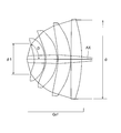
- FIG. 4 shows the relationship between the most effective object-side effective diameter ⁇ 1 and the maximum effective diameter ⁇ in the ultraviolet optical system.
- FIG. 4 shows the case where the lens surface having the maximum effective diameter ⁇ exists in the objective lens group GrF, but the same applies when it exists in the imaging lens group.
- the lens surface on the most object side has a concave shape on the object side and the following conditional expression (2) is satisfied.
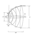
- WD Distance from the most object side position of the most object side lens to the measurement area with respect to the ultraviolet light source
- ⁇ 2 Effective diameter of measurement area for ultraviolet light source
- ⁇ 1 Effective diameter of the lens surface located closest to the object in the objective lens group
- ⁇ The angle formed by the main ray of the luminous flux at the maximum measurement angle with the optical axis.
- FIG. 5 shows the relationship between the effective diameter of the measurement area ⁇ 2 and the working distance WD in the ultraviolet optical system.
- the angle formed by the optical axis when the on-axis ray travels away from the optical axis is positive, it is desirable that the angle ⁇ formed by the main ray of the off-axis luminous flux and the optical axis in the intermediate image is positive.
- the off-axis main ray is parallel to the optical axis in the intermediate image plane so that the angular characteristic has linearity in the spatial direction.
- the angle ⁇ between the main ray of the off-axis luminous flux and the optical axis is set to plus in the intermediate image, the imaging performance on the sensor receiving surface between the objective lens group in the front stage and the imaging lens group in the rear stage It is possible to optimize comprehensively.
- the objective lens group in the previous stage gives priority to capturing at a wider angle, and allows the main ray of off-axis light to have an angle remaining on the intermediate image plane. That is, it is not necessary to bend the image until it is parallel to the optical axis, and since the optical materials used are limited, the imaging performance of the intermediate image is not a problem. Since the image may be formed in a plane on the light receiving surface of the sensor, the off-axis main ray in the intermediate image may have a positive angle. Therefore, in the rear-stage imaging lens group, the imaging performance can be optimized as a whole by not only controlling the magnification but also correcting the angular characteristics remaining in the front-stage objective lens group.
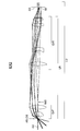
- FIG. 1 shows the optical configuration of the ultraviolet optical system LN and the light distribution measuring device LU according to the first embodiment in an optical cross section
- FIG. 2 shows the ultraviolet optical system LN and the ultraviolet optical system LN according to the second embodiment.
- the optical configuration of the light distribution measuring device LU is shown by an optical cross section.
- the light distribution measuring device LU according to the first and second embodiments has an ultraviolet optical system LN that captures ultraviolet light for each angle from an ultraviolet light source at once and forms an image as an optical image IM, and a sensor light receiving surface SS. It is equipped with a two-dimensional sensor (image sensor) SR that converts the optical image IM formed above into an electrical signal, and outputs the light distribution of an ultraviolet light source using the signal obtained by the two-dimensional sensor SR. It is configured to do.
- image sensor image sensor
- the ultraviolet optical system LN reimages the objective lens group GrF that captures ultraviolet light for each angle from an ultraviolet light source to form an intermediate image IM0 and the intermediate image IM0. It is composed of an imaging lens group GrR.
- the objective lens group GrF In the ultraviolet optical system LN (FIG. 1) of the first embodiment, the objective lens group GrF is composed of three positive single lenses, and the imaging lens group GrR is five positive, negative, positive, positive, and positive single lenses. It consists of a lens.
- the objective lens group GrF is composed of three positive single lenses, and the imaging lens group GrR is five positive / negative positive / negative single lenses. It consists of.
- the objective lens group GrF and the imaging lens group GrR both have no joint surface and are composed of only a single lens that transmits ultraviolet light having a wavelength of 300 nm or less. Since the ultraviolet region is narrower than the visible light region, it is possible to obtain high optical performance by combining single lenses without using a bonded lens.
- the measurement area AR for the ultraviolet light source corresponds to the object surface OB of the ultraviolet optical system LN. When a sample of the ultraviolet light source to be evaluated is arranged in the measurement area AR, the ultraviolet light emitted from the ultraviolet light source at each radiation angle is bent by the ultraviolet optical system LN.
- the strong power of the objective lens group GrF bends ultraviolet light with a wide radiation angle to form an intermediate image IM0, and the intermediate image IM0 is reimaged with the imaging lens group GrR.
- the angle of capture from the measurement area AR can be widened.
- the brightness can be adjusted by using a diaphragm as needed.
- the difference between the minimum face-to-face distance and the maximum face-to-face distance between all lens surfaces of the ultraviolet optical system LN is greater than or equal to the working distance. Since the unnecessary light generated by the reflection on the lens surfaces that are inclined to each other travels to the peripheral portion of the lens (FIG. 3), the unnecessary light that reaches the two-dimensional sensor SR is reduced. As a result, the detection error due to unnecessary light is effectively reduced, and high-precision light distribution measurement of the ultraviolet light source becomes possible.
- the two-dimensional sensor SR has a light receiving sensitivity of ultraviolet light having a wavelength of 300 nm or less, and the optical system LN for ultraviolet rays is located on the sensor light receiving surface SS so that the intermediate image IM0 is reimaged as an optical image IM. ..
- the optical image IM formed on the sensor light receiving surface SS by the reimaging of the intermediate image IM0 is converted into an electrical signal by the two-dimensional sensor SR. Since the optical image IM includes the light distribution information of the ultraviolet light source as a radiation angle distribution, the light distribution characteristic of the ultraviolet light source can be obtained by the light distribution measuring device LU.
- An optical system for ultraviolet rays wherein neither the objective lens group nor the imaging lens group has a bonding surface and is composed of only a single lens that transmits ultraviolet light having a wavelength of 300 nm or less.
- (# 2) The ultraviolet optical system according to (# 1), wherein the difference between the minimum surface distance and the maximum surface distance is equal to or greater than the working distance between all lens surfaces.
- (# 4) Any one of (# 1) to (# 3), characterized in that the lens surface on the most object side has a concave shape on the object side and satisfies the following conditional expression (2).
- Optical system for ultraviolet rays described in the section; ⁇ 2> WD ... (2) However, WD: Distance from the most object side position of the most object side lens to the measurement area with respect to the ultraviolet light source, ⁇ 2: Effective diameter of measurement area for ultraviolet light source, And ⁇ 1: Effective diameter of the lens surface located closest to the object in the objective lens group, ⁇ : The angle formed by the main ray of the luminous flux at the maximum measurement angle with the optical axis, Then ⁇ 1 ⁇ 2 + 2WDtan ⁇ Is.
- (# 6) The ultraviolet optical system according to any one of (# 1) to (# 5) and a sensor that converts an optical image formed on a light receiving surface of the sensor into an electrical signal.
- a light distribution measuring device that outputs the light distribution of the ultraviolet light source by using the signal obtained by the sensor.
- a light distribution measuring device characterized in that the optical system for ultraviolet rays is positioned so that the intermediate image is reimaged on the light receiving surface of the sensor, and the sensor has a light receiving sensitivity of ultraviolet light having a wavelength of 300 nm or less.
- Examples 1 and 2 (EX1, 2) given here are numerical examples corresponding to the above-mentioned first and second embodiments, respectively, and are lens configuration diagrams representing the first and second embodiments. (FIGS. 1 and 2) show the corresponding optical configurations of Examples 1 and 2, respectively.
- the surface data the surface number i (OB: object surface, IM: image surface), the radius of curvature ri (mm) on the paraxial axis, and the shaft top surface spacing (core thickness) are arranged in order from the left column.
- the di (mm), the refractive index n (300) for ultraviolet light having a wavelength of 300 nm, and the effective radius Ri (mm) are shown.
- the focal length f (mm), F number (Fno), sensor size Y half the diagonal length of the sensor light receiving surface SS, mm
- the main ray of the light beam of the maximum measurement angle are included.
- the angle ⁇ (°) formed by the optical axis AX, the angle ⁇ (°) formed by the main ray of the off-axis light beam and the optical axis AX in the intermediate image IM0, the f-number corresponding to the conditional expression of each embodiment, and the related data are shown.
- Each of the single lenses used in each embodiment has a refractive index of 1.5 for ultraviolet light having a wavelength of 300 nm and a transmittance of 97% or more for ultraviolet light having a wavelength of 300 nm.
- Specific examples of the optical materials constituting these single lenses include CaF 2 , BaF 2 , and SiO 2 .
- the ultraviolet optical system LN of Example 1 has a configuration that is easy to implement. For example, a small two-dimensional sensor SR, which has a small sensor size Y and is easily available, is assumed. Further, the maximum effective diameter ⁇ of the lens surface in the entire system is suppressed to 83.04 mm, which is not so large as the maximum lens diameter.
- the F number is as bright as 2.4, so it is easy to measure, and the main ray angle ⁇ , which is the maximum measurement angle, also supports up to 70 degrees, which is perfect.
- the ultraviolet optical system LN of Example 2 has a configuration that realizes a larger maximum measurement angle ⁇ .
- the sensor size Y is large, and it is set so that measurement can be performed without reducing the resolution of the angle.
- the maximum effective diameter ⁇ of the lens surface in the entire system is suppressed to 86.5 mm, and the maximum lens diameter is not so large.
- the main ray angle ⁇ of the maximum measurement angle corresponds to up to 80 degrees, which is a stricter configuration as an optical system. Since the angle ⁇ is negatively large, there is no design margin as compared with the first embodiment, and there is an overcorrection situation.
- the ultraviolet optical system LN of Examples 1 and 2 By using the ultraviolet optical system LN of Examples 1 and 2, it is possible to capture the ultraviolet light for each angle from the ultraviolet light source at once and form an image on the sensor light receiving surface SS of the two-dimensional sensor SR. Then, by using the light distribution measuring device LU provided with the ultraviolet optical system LN, it is possible to perform high-precision light distribution measurement of the ultraviolet light source at once.
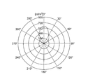
- the graph of FIG. 6 shows an outline of the light distribution measurement results obtained by the light distribution measuring devices LU of Examples 1 and 2. From this measurement result, it can be seen that the ultraviolet light source has a light distribution characteristic with strong radiance in a specific angular direction.
- Example 1 Unit mm Surface data i ri di n (300) Ri 1 (OB) infinity 3.000 1.50 2 -13.717 11.624 1.5 5.98 3 -12.612 0.200 11.95 4-97.685 11.188 1.5 18.68 5 -26.296 1.144 20.60 6 239.025 12.011 1.5 25.61 7 -51.762 169.179 26.35 8 150.844 16.881 1.5 41.52 9 -110.528 0.200 41.42 10 79.159 2.000 1.5 37.07 11 43.767 97.030 34.14 12 101.771 15.000 1.5 41.51 13 -1091.247 54.216 41.01 14 65.735 13.027 1.5 30.91 15 -528.752 0.230 29.67 16 32.270 9.618 1.5 24.01 17 60.522 38.172 22.00 18 (IM) infinity 0.000 8.50
- Example 2 Unit mm Surface data i ri di n (300) Ri 1 (OB) infinity 3.975 1.50 2 -11.881 9.505 1.5 7.75 3 -12.327 0.200 12.17 4 -172.972 20.813 1.5 25.84 5 -30.081 12.334 28.25 6 114.815 19.988 1.5 42.71 7 -109.924 194.851 42.97 8 199.638 17.755 1.5 43.25 9 -97.910 57.375 43.14 10 -39.297 15.000 1.5 23.64 11 -90.705 104.198 26.16 12 118.249 15.000 1.5 31.75 13 -81.781 9.880 31.49 14 49.330 13.258 1.5 23.96 15 -398.203 3.869 21.63 16 -71.533 2.000 1.5 21.24 17 -499.788 50.000 20.81 18 (IM) infinity 0.000 12.85
Landscapes
- Physics & Mathematics (AREA)
- General Physics & Mathematics (AREA)
- Spectroscopy & Molecular Physics (AREA)
- Optics & Photonics (AREA)
- Health & Medical Sciences (AREA)
- Toxicology (AREA)
- Chemical & Material Sciences (AREA)
- Analytical Chemistry (AREA)
- Engineering & Computer Science (AREA)
- Signal Processing (AREA)
- Multimedia (AREA)
- Photometry And Measurement Of Optical Pulse Characteristics (AREA)
- Lenses (AREA)
Priority Applications (2)
| Application Number | Priority Date | Filing Date | Title |
|---|---|---|---|
| JP2021520050A JPWO2020235145A1 (cg-RX-API-DMAC7.html) | 2019-05-23 | 2020-02-03 | |
| US17/613,344 US11914119B2 (en) | 2019-05-23 | 2020-02-03 | Ultraviolet optical system and light distribution measuring apparatus |
Applications Claiming Priority (2)
| Application Number | Priority Date | Filing Date | Title |
|---|---|---|---|
| JP2019-096586 | 2019-05-23 | ||
| JP2019096586 | 2019-05-23 |
Publications (1)
| Publication Number | Publication Date |
|---|---|
| WO2020235145A1 true WO2020235145A1 (ja) | 2020-11-26 |
Family
ID=73459063
Family Applications (1)
| Application Number | Title | Priority Date | Filing Date |
|---|---|---|---|
| PCT/JP2020/003948 Ceased WO2020235145A1 (ja) | 2019-05-23 | 2020-02-03 | 紫外線用光学系及び配光測定装置 |
Country Status (3)
| Country | Link |
|---|---|
| US (1) | US11914119B2 (cg-RX-API-DMAC7.html) |
| JP (1) | JPWO2020235145A1 (cg-RX-API-DMAC7.html) |
| WO (1) | WO2020235145A1 (cg-RX-API-DMAC7.html) |
Families Citing this family (1)
| Publication number | Priority date | Publication date | Assignee | Title |
|---|---|---|---|---|
| CN116416164B (zh) * | 2023-06-09 | 2023-08-15 | 国网山东省电力公司电力科学研究院 | 一种紫外光路成像分辨率优化方法 |
Citations (5)
| Publication number | Priority date | Publication date | Assignee | Title |
|---|---|---|---|---|
| JPH09264782A (ja) * | 1996-03-28 | 1997-10-07 | Minolta Co Ltd | 2次元配光分布測定装置及び2次元配光分布測定用光学系 |
| JPH103033A (ja) * | 1996-06-17 | 1998-01-06 | Nikon Corp | 液浸系対物レンズ |
| JPH11295606A (ja) * | 1998-04-07 | 1999-10-29 | Nikon Corp | 直筒型反射屈折光学系 |
| JP2002311332A (ja) * | 2001-04-06 | 2002-10-23 | Leica Microsystems Semiconductor Gmbh | 検査用顕微鏡およびそのための対物レンズ |
| US20130250434A1 (en) * | 2010-12-01 | 2013-09-26 | Shanghai Micro Electronics Equipment Co., Ltd. | Projection objective lens system |
Family Cites Families (3)
| Publication number | Priority date | Publication date | Assignee | Title |
|---|---|---|---|---|
| JP3594706B2 (ja) | 1995-08-22 | 2004-12-02 | 浜松ホトニクス株式会社 | 光源位置調整装置 |
| KR101391470B1 (ko) * | 2004-05-17 | 2014-05-07 | 칼 짜이스 에스엠티 게엠베하 | 중간이미지를 갖는 카타디옵트릭 투사 대물렌즈 |
| DE102014112199B4 (de) * | 2014-08-26 | 2024-10-10 | Carl Zeiss Microscopy Gmbh | Mikroskopisches Abbildungssystem |
-
2020
- 2020-02-03 JP JP2021520050A patent/JPWO2020235145A1/ja active Pending
- 2020-02-03 US US17/613,344 patent/US11914119B2/en active Active
- 2020-02-03 WO PCT/JP2020/003948 patent/WO2020235145A1/ja not_active Ceased
Patent Citations (5)
| Publication number | Priority date | Publication date | Assignee | Title |
|---|---|---|---|---|
| JPH09264782A (ja) * | 1996-03-28 | 1997-10-07 | Minolta Co Ltd | 2次元配光分布測定装置及び2次元配光分布測定用光学系 |
| JPH103033A (ja) * | 1996-06-17 | 1998-01-06 | Nikon Corp | 液浸系対物レンズ |
| JPH11295606A (ja) * | 1998-04-07 | 1999-10-29 | Nikon Corp | 直筒型反射屈折光学系 |
| JP2002311332A (ja) * | 2001-04-06 | 2002-10-23 | Leica Microsystems Semiconductor Gmbh | 検査用顕微鏡およびそのための対物レンズ |
| US20130250434A1 (en) * | 2010-12-01 | 2013-09-26 | Shanghai Micro Electronics Equipment Co., Ltd. | Projection objective lens system |
Also Published As
| Publication number | Publication date |
|---|---|
| JPWO2020235145A1 (cg-RX-API-DMAC7.html) | 2020-11-26 |
| US20220221697A1 (en) | 2022-07-14 |
| US11914119B2 (en) | 2024-02-27 |
Similar Documents
| Publication | Publication Date | Title |
|---|---|---|
| JP6064105B1 (ja) | 内視鏡対物光学系 | |
| US7106529B2 (en) | Flat wide-angle lens system | |
| CN109656006B (zh) | 一种宽谱段非调焦全天空气辉成像仪 | |
| JP2011100094A5 (cg-RX-API-DMAC7.html) | ||
| JP6255268B2 (ja) | 大開口数で撮像するための多重反射素子を有する反射屈折光学系 | |
| CN107430260B (zh) | 斜视物镜光学系统和具备该斜视物镜光学系统的斜视用内窥镜 | |
| US20130003168A1 (en) | Infrared Zoom Lens | |
| CN103823294A (zh) | 具有超长焦距的连续变焦中波红外光学系统 | |
| JP2014109741A (ja) | 集光光学系、照明光学系および画像投射装置 | |
| JP2016008979A (ja) | 撮像装置 | |
| JP2015045887A (ja) | 広スペクトル対応のRoss式補正がなされたカセグレン式望遠鏡 | |
| JP6879723B2 (ja) | カタディオプトリック光学系、撮像装置および人工衛星 | |
| CN113504654A (zh) | 一种近眼显示光学系统 | |
| JP2021117343A (ja) | 光学系およびそれを有する撮像装置 | |
| KR20200026692A (ko) | 광학 이미징 렌즈 | |
| JPWO2017221947A1 (ja) | 撮像用の光学系および撮像装置 | |
| US8456762B2 (en) | Observation optical system | |
| TWI913117B (zh) | 光學透鏡組 | |
| JP2013029654A5 (cg-RX-API-DMAC7.html) | ||
| JP2011248122A5 (cg-RX-API-DMAC7.html) | ||
| US11914119B2 (en) | Ultraviolet optical system and light distribution measuring apparatus | |
| CN209417404U (zh) | 一种宽谱段非调焦全天空气辉成像仪 | |
| WO2020153355A1 (ja) | 光学系、光学機器、撮像装置、並びに、光学系及び撮像装置の製造方法 | |
| CN114137735B (zh) | 一种大孔径长截距的ims光谱成像系统准直镜头 | |
| CN115390218B (zh) | 光学投影镜头和相应的ar投影设备 |
Legal Events
| Date | Code | Title | Description |
|---|---|---|---|
| 121 | Ep: the epo has been informed by wipo that ep was designated in this application |
Ref document number: 20808628 Country of ref document: EP Kind code of ref document: A1 |
|
| ENP | Entry into the national phase |
Ref document number: 2021520050 Country of ref document: JP Kind code of ref document: A |
|
| NENP | Non-entry into the national phase |
Ref country code: DE |
|
| 122 | Ep: pct application non-entry in european phase |
Ref document number: 20808628 Country of ref document: EP Kind code of ref document: A1 |