WO2020235111A1 - フィルターユニット、流体の分離装置及び分離方法 - Google Patents
フィルターユニット、流体の分離装置及び分離方法 Download PDFInfo
- Publication number
- WO2020235111A1 WO2020235111A1 PCT/JP2019/020561 JP2019020561W WO2020235111A1 WO 2020235111 A1 WO2020235111 A1 WO 2020235111A1 JP 2019020561 W JP2019020561 W JP 2019020561W WO 2020235111 A1 WO2020235111 A1 WO 2020235111A1
- Authority
- WO
- WIPO (PCT)
- Prior art keywords
- filter
- nanowindow
- fluid
- flexible
- conductive
- Prior art date
- Legal status (The legal status is an assumption and is not a legal conclusion. Google has not performed a legal analysis and makes no representation as to the accuracy of the status listed.)
- Ceased
Links
Images


Classifications
-
- B—PERFORMING OPERATIONS; TRANSPORTING
- B01—PHYSICAL OR CHEMICAL PROCESSES OR APPARATUS IN GENERAL
- B01D—SEPARATION
- B01D61/00—Processes of separation using semi-permeable membranes, e.g. dialysis, osmosis or ultrafiltration; Apparatus, accessories or auxiliary operations specially adapted therefor
- B01D61/42—Electrodialysis; Electro-osmosis ; Electro-ultrafiltration; Membrane capacitive deionization
- B01D61/44—Ion-selective electrodialysis
- B01D61/445—Ion-selective electrodialysis with bipolar membranes; Water splitting
-
- B—PERFORMING OPERATIONS; TRANSPORTING
- B01—PHYSICAL OR CHEMICAL PROCESSES OR APPARATUS IN GENERAL
- B01D—SEPARATION
- B01D61/00—Processes of separation using semi-permeable membranes, e.g. dialysis, osmosis or ultrafiltration; Apparatus, accessories or auxiliary operations specially adapted therefor
- B01D61/42—Electrodialysis; Electro-osmosis ; Electro-ultrafiltration; Membrane capacitive deionization
- B01D61/44—Ion-selective electrodialysis
- B01D61/54—Controlling or regulating
-
- B—PERFORMING OPERATIONS; TRANSPORTING
- B01—PHYSICAL OR CHEMICAL PROCESSES OR APPARATUS IN GENERAL
- B01D—SEPARATION
- B01D69/00—Semi-permeable membranes for separation processes or apparatus characterised by their form, structure or properties; Manufacturing processes specially adapted therefor
- B01D69/02—Semi-permeable membranes for separation processes or apparatus characterised by their form, structure or properties; Manufacturing processes specially adapted therefor characterised by their properties
-
- B—PERFORMING OPERATIONS; TRANSPORTING
- B01—PHYSICAL OR CHEMICAL PROCESSES OR APPARATUS IN GENERAL
- B01D—SEPARATION
- B01D71/00—Semi-permeable membranes for separation processes or apparatus characterised by the material; Manufacturing processes specially adapted therefor
- B01D71/02—Inorganic material
- B01D71/021—Carbon
- B01D71/0211—Graphene or derivates thereof
-
- B—PERFORMING OPERATIONS; TRANSPORTING
- B01—PHYSICAL OR CHEMICAL PROCESSES OR APPARATUS IN GENERAL
- B01D—SEPARATION
- B01D71/00—Semi-permeable membranes for separation processes or apparatus characterised by the material; Manufacturing processes specially adapted therefor
- B01D71/02—Inorganic material
- B01D71/021—Carbon
- B01D71/0212—Carbon nanotubes
-
- B—PERFORMING OPERATIONS; TRANSPORTING
- B01—PHYSICAL OR CHEMICAL PROCESSES OR APPARATUS IN GENERAL
- B01D—SEPARATION
- B01D2311/00—Details relating to membrane separation process operations and control
- B01D2311/24—Quality control
- B01D2311/243—Electrical conductivity control
-
- B—PERFORMING OPERATIONS; TRANSPORTING
- B01—PHYSICAL OR CHEMICAL PROCESSES OR APPARATUS IN GENERAL
- B01D—SEPARATION
- B01D2313/00—Details relating to membrane modules or apparatus
- B01D2313/34—Energy carriers
- B01D2313/345—Electrodes
-
- B—PERFORMING OPERATIONS; TRANSPORTING
- B01—PHYSICAL OR CHEMICAL PROCESSES OR APPARATUS IN GENERAL
- B01D—SEPARATION
- B01D2325/00—Details relating to properties of membranes
- B01D2325/02—Details relating to pores or porosity of the membranes
- B01D2325/0282—Dynamic pores-stimuli responsive membranes, e.g. thermoresponsive or pH-responsive
-
- B—PERFORMING OPERATIONS; TRANSPORTING
- B01—PHYSICAL OR CHEMICAL PROCESSES OR APPARATUS IN GENERAL
- B01D—SEPARATION
- B01D2325/00—Details relating to properties of membranes
- B01D2325/26—Electrical properties
-
- B—PERFORMING OPERATIONS; TRANSPORTING
- B82—NANOTECHNOLOGY
- B82Y—SPECIFIC USES OR APPLICATIONS OF NANOSTRUCTURES; MEASUREMENT OR ANALYSIS OF NANOSTRUCTURES; MANUFACTURE OR TREATMENT OF NANOSTRUCTURES
- B82Y30/00—Nanotechnology for materials or surface science, e.g. nanocomposites
Definitions
- the present disclosure relates to a filter unit, a fluid separation device, and a separation method.
- distillation is widely used as a process for obtaining the N 2, O 2 and high purity product such as a noble gas. Distillation involves a phase change that turns a liquid into a gas, so it consumes a large amount of energy.
- phase change-based molecular separation such as distillation
- membrane-based molecular separation is required.
- the membrane-based separation technique can be realized with a simpler device than the conventional technique based on the phase change.
- Examples of the membrane used in the separation technique include a carbon material such as a single-layer graphene membrane having permeation holes.
- the raw graphene sheet cannot permeate even the smallest gas such as He. Therefore, in order to apply graphene to the separation technique, it is necessary to form nanowindows.
- a carbon material equipped with a nanowindow is considered to be promising as a film material having excellent molecular separation selectivity and high energy efficiency.
- the gaps between carbon nanotubes and the gaps between carbon nanohorns also exhibit the same properties as nanowindows. Therefore, it can be a material for a filter having high energy efficiency. Therefore, it would be extremely useful if there was a filter unit capable of separating molecules using a carbon material.
- the present disclosure provides a filter unit, a separation device, and a separation method capable of separating a fluid with high accuracy.
- the filter unit includes a conductive filter having a transmission hole, a pair of electrodes for applying a voltage to the conductive filter, and an insulator for preventing a current from flowing between the pair of electrodes. Be prepared.
- the fluid introduced into the filter unit can be separated with high accuracy, for example, at the molecular level. Since the filter unit can separate the fluid based on the electrostatic interaction, it is not necessary to increase the pressure of the fluid. Therefore, the energy cost required for fluid separation can be reduced.
- the transmission hole of the filter unit may include a flexible nanowindow in which the orientation of two or more functional groups formed on the rim can be switched by applying a voltage.
- the pair of electrodes may change the molecular selectivity or the molecular permeability of the carbon filter by applying a voltage to the carbon filter.
- the fluid separating device includes the above-mentioned filter unit, an introduction unit for introducing the fluid into the filter unit, and a derivation unit for deriving the fluid from the filter unit, and the derivation unit is a pair of electrodes. It is provided with a branch portion that switches the fluid derivation destination in conjunction with a change in the voltage applied to the carbon filter.
- This separation device may include a control unit that controls the switching operation of the branch unit based on the change in voltage.
- the fluid separation method is a separation method for separating a fluid using a conductive filter having a transmission hole, and a voltage is applied to the conductive filter in a state where the conductive filter is electrically insulated. It has a step of changing the distribution of electric charge in the through hole or the size of the through hole by applying the voltage. According to this step, for example, the fluid can be separated with high accuracy. Since the filter unit can separate the fluid based on the potential difference, it is not necessary to increase the pressure of the fluid. Therefore, the energy cost required for fluid separation can be reduced.
- the permeation hole may include a flexible nanowindow in which the orientation of two or more functional groups formed on the rim can be switched by applying a voltage.
- the molecular selectivity or the molecular permeability of the conductive filter may be changed by applying a voltage to the conductive filter. As a result, the fluid can be separated at the molecular level with high accuracy.
- the separation method may include a step of switching the fluid derivation destination in conjunction with a change in the voltage of the conductive filter. According to this fluid separation method, the derivation destination of the two separated fluids can be automatically switched.
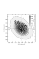
- This figure shows a 2D histogram contour of the distance between two pairs of oxygen atoms at opposite poles in the rims that make up the nanowindow. It is a figure which shows two pairs of oxygen atoms (the pair of O1 and O2, the pair of O3 and O4) used for the calculation of the distance of FIG.
- the filter unit includes a conductive filter, an insulator, and a pair of electrodes. This filter unit is used, for example, for separating a gas phase or a liquid phase, or removing foreign substances (molecules).
- the conductive filter has conductivity.
- the conductive filter include a carbon filter, but the present invention is not limited to this, and the conductive filter may be made of other materials.
- the material of the carbon filter include nanocarbon. Specific examples thereof include graphene, carbon nanotubes, carbon nanoribbons, carbon nanohorns, graphene oxide, and diamond-like carbon.
- a thin film of a carbon precursor such as an acrylic resin may be carbonized.
- the present invention is not limited to these, and any carbon material capable of forming through-holes having a highly uniform size can be appropriately used.
- it may be an electrically conductive carbon particle, for example, an electrically conductive carbon particle such as acetylene black, or a conductive carbon black such as Cabot's Vulcan XC72 (trade name).
- the conductive filter may be in the form of a film.
- the nanotube ink or slurry used for forming the film-like conductive filter is at least one selected from the group consisting of a dispersant, a binder, conductive particles (such as nafion and an ionic liquid), and a thickener, if necessary. It may be included.
- the conductive filter has through holes.
- the shape of the through hole is not particularly limited.
- the size of the through hole may be 10 ⁇ m or less in diameter when converted into a circle having the same area. Molecules that can pass through the through holes and molecules that cannot pass through the through holes can be separated by a filter unit provided with a conductive filter.
- the transmission hole may be a nanowindow.
- a nanowindow is a window (gap) of nanoscale size.
- the periphery of the nanowindow may be composed of a single layer of carbon atoms. Substances (molecules) smaller than the size of the nanowindow can permeate the carbon filter at ultra-high speed, for example, without being hindered by the nanowindow.
- Nanowindows may be formed by perforating a film such as graphene by high temperature oxidation or other chemical methods.
- the carbon filter is a film formed by aggregating carbon nanotubes or carbon nanohorns
- the gap between carbon nanotubes, between carbon nanohorns, or between carbon nanotubes and carbon nanohorns may be used as a nanowindow.
- Examples of the conductive filter other than the carbon filter include ITO having a porous structure and a metal film such as a platinum thin film having nanothrough holes.
- the pair of electrodes may have, for example, a working electrode and a counter electrode (counter electrode).
- the pair of electrodes applies a voltage to the conductive filter.
- the electrode preferably has high conductivity and corrosion resistance when used in a liquid. Examples of the electrode material include platinum, copper, copper, and the like whose surface is platinum-plated.
- the highly conductive carbon filter itself can also be used as a working electrode.
- a liquid phase electrode such as a salt bridge can also be used.
- the efficiency of the liquid phase electrode is not very high, but there is an advantage that a standard electrode can be used.
- the insulator has a function of electrically insulating the working electrode and the counter electrode. A voltage is applied to the conductive filter by the working electrode and the current is prevented from flowing by the insulator. As a result, power consumption can be suppressed.
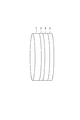
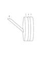
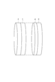
- FIG. 1 to 6 are diagrams schematically showing an example of arrangement of each component constituting the filter unit.
- one surface of the film-shaped conductive filter 1 is in contact with one surface of the disk-shaped working electrode 2.
- the other surface of the conductive filter 1 is in contact with one surface of the disc-shaped insulator 4.
- the other surface of the insulator 4 is in contact with the counter electrode 3.
- the conductive filter 1 is in contact with one surface of the disk-shaped working electrode 2, and one surface of the disk-shaped insulator 4 is in contact with the other surface of the working electrode 2.
- the other surface of the insulator 4 is in contact with the counter electrode 3.
- the working electrode 2 is arranged apart from the conductive filter, and the working electrode 2 and the conductive filter 1 are electrically connected to each other through the liquid. It may be in contact.
- One surface of the insulator 4 is in contact with the other surface of the conductive filter 1.
- the other surface of the insulator 4 is in contact with the counter electrode 3.
- FIG. 4 the end of the rod-shaped working electrode 2 is in contact with one surface of the conductive filter 1.
- One surface of the insulator 4 is in contact with the other surface of the conductive filter 1. Since it is preferable that a sufficient voltage can be applied to the conductive filter 1 without bias, FIGS. 1 and 2 are preferable.
- the conductive filter 1 and the insulator 4 are arranged apart from each other. Except for this point, it is the same as FIG.
- Another object or a second conductive filter may be sandwiched between the counter electrode 3 and the insulator 4.
- the counter electrode 3 and the insulator 4 are arranged apart from each other. Except for this point, it is the same as FIG.
- the members When arranging the filter unit in the liquid, the members may be arranged apart from each other as shown in FIGS. 5 and 6.
- each member in the filter unit is not limited to the above example.
- two or more conductive filters 1 may be arranged, two or more pairs of electrodes 2 and 3 may be arranged, and the insulator 4 may also be arranged. There may be two or more.
- FIG. 7 is a diagram showing an embodiment of the filter unit.
- the filter unit 10 of FIG. 7 includes a filter holder 6 and a laminated body 15 housed in the filter holder 6.
- the laminate 15 includes a working electrode 2, a conductive filter 1a, a membrane filter 5, a conductive filter 1b, and a counter electrode 3 from the upstream side along the flow direction of the fluid.
- the conductive filters 1a and 1b may be, for example, carbon filters formed by adhering single-walled carbon nanotubes to a polycarbonate membrane filter 5.
- the method of attaching the single-walled carbon nanotubes may be, for example, spray coating.
- the conductive filters 1a and 1b are not limited to such a manufacturing method, and may be formed by bar-coding and drying a slurry of single-walled carbon nanotubes of a polycarbonate membrane filter.
- the gap between the carbon nanotubes functions as a transmission hole.
- the membrane filter 5 functions as an insulator.
- the membrane filter 5 is sandwiched between a pair of conductive filters 1a and 1b.
- the pair of conductive filters 1a and 1b and the disc-shaped electrodes 2 and 3 made of platinum mesh are in contact with each other so that the electrodes 2 and 3 sandwich the conductive filters 1a and 1b from the outside.
- the working electrode 2 is arranged on the upstream side of the conductive filters 1a and 1b
- the counter electrode 3 is arranged on the downstream side along the flow direction of the fluid.
- the arrangement is not limited to this, and the counter electrode 3 may be arranged on the upstream side and the working electrode 2 may be arranged on the downstream side.
- FIG. 8 is a diagram showing another embodiment of the filter unit.
- the filter unit 11 of FIG. 8 includes a filter holder 6 and a laminated body 15a housed in the filter holder 6.
- the laminated body 15a includes a working electrode 2, a conductive filter 1a, a membrane filter 5, a conductive filter 1b, and a counter electrode 3 from the upstream side along the flow direction of the fluid.
- the thickness of the counter electrode 3 is larger than that of the counter electrode 3 in the example of FIG. In this way, the thickness of each member may be changed as appropriate.
- the counter electrode 3 may be formed of carbon paper.
- the filter unit of the present disclosure is not limited to the embodiments shown in FIGS. 7 and 8.
- the filter unit 10 (11) may include a laminate as described with reference to FIGS. 1 to 6.
- the shape of the filter holder 6 is not particularly limited as long as it has a structure that allows the fluid to come into contact with the laminate.
- FIG. 9 is a diagram showing an embodiment of the separation device.
- the separation device 100 includes a filter unit 10, an introduction unit 30 for introducing a fluid into the filter unit 10, and a derivation unit 40 for deriving the fluid from the filter unit 10.
- the filter unit 10 may be the filter unit 11 shown in FIG. 8 or another filter unit.
- the power supply device 20 is electrically connected to the electrodes 2 and 3. By operating the power supply device 20, the potential difference between the electrodes 2 and 3 can be controlled. When a potential difference occurs between the electrodes 2 and 3, a voltage is applied to the conductive filters 1a and 1b to generate an electric charge.
- the lead-out section 40 includes a branch section 9 that switches the lead-out destination of the fluid in conjunction with a change in the voltage applied to the conductive filters 1a and 1b by the pair of electrodes 2 and 3. By using such a branching portion 9, it is possible to perform a branching step of switching the fluid derivation destination in conjunction with a change in the voltage of the conductive filters 1a and 1b.
- the branch portion 9 may be, for example, a three-way valve.
- the lead-out unit 40 includes a main flow path 7 connected to the filter unit 11 and guiding the fluid to the branch section 9, and two branch flow paths 8a and 8b connected to the branch section 9.
- a control signal from the control unit 50 is input to the branch unit 9.
- Information regarding the potential difference between the electrodes 2 and 3 is input from the power supply device 20 to the control unit 50.
- the branching unit 9 can selectively switch the fluid lead-out destination to the branch flow path 8a or the branch flow path 8b by the control signal from the control unit 50.
- the control unit 50 outputs a control signal for operating the branch unit 9 based on the voltage information from the power supply device 20, for example, a CPU (Central Processing Unit), a ROM (Read Only Memory), and a RAM. (Random Access Memory) and an input / output interface and the like may be provided. However, it is not essential to include such a control unit 50. For example, the voltage information from the power supply device 20 may be directly input to the branch portion 9.
- a CPU Central Processing Unit
- ROM Read Only Memory
- RAM Random Access Memory
- an input / output interface and the like may be provided. However, it is not essential to include such a control unit 50.
- the voltage information from the power supply device 20 may be directly input to the branch portion 9.
- the separation device 100 can separate the fluid into two by the branch portion 9 switching the extraction destination of the fluid.
- the number of separated fluids is not limited to two, and the fluid may be separated into three or more.
- the control unit 50 may perform an operation of switching the fluid derivation destination by the branch unit 9 at a predetermined time difference from the operation of the power supply device 20. For example, if the time difference is set in consideration of the time possessed by the flow of the main flow path 7, the fluid separation accuracy can be further improved.
- the ionic solution is separated into a high-concentration cation solution on the upstream side of the conductive filter 1 (1a) and a low-concentration cation solution on the downstream side.
- one branch flow path 8b communicates with the main flow path 7 to branch soft water. It can be led to the downstream side of the flow path 8b.
- the branch flow path 8a communicates with the main flow path 7, and water having a high alkali metal ion concentration can be led out to the downstream side of the branch flow path 8a.
- the cathode (working electrode 2) is brought into contact with the cathode (working electrode 2) from the downstream side of the conductive filter 1 to apply a voltage, and the anode (counter electrode 3) is arranged on the upstream side across the insulator 4. .
- a voltage is applied to the conductive filter 1
- anions sica ions or the like
- water are attracted to the anode and are difficult to permeate through the conductive filter 1, so that water having a low anion concentration can be separated from the water.
- the filter unit of the present disclosure attracts ions by electric charge to separate the fluid. That is, since the fluid can be separated by utilizing the change in the distribution of electric charges in the through holes of the conductive filter, it is not necessary to change the pressure of the fluid such as gas or liquid. Therefore, the energy cost required for fluid separation can be reduced. Further, when the voltage application is turned off, the object separated on the upstream side of the conductive filter 1 also flows on the downstream side. Therefore, it is difficult for the object to accumulate on the upstream side as in the conventional filtration. Therefore, the frequency of maintenance such as filter replacement can be reduced. Further, since the fluid is separated by using electrostatic attractive force and repulsive force, high-performance separation can be realized at a lower energy cost than the conventional membrane.
- the branch flow paths 8a, 8b communicating with the main flow path 7 are selectively selected in conjunction with the application of the voltage to the conductive filter 1 (1a, 1b).
- the branch portion 9 for switching to the fluid is separated into two, and the two fluids (the first fluid and the second fluid) are separately derived into the branch flow path 8a and the branch flow path 8b. Can be done.
- the conductive filter of the filter unit of the present disclosure may be a carbon filter having a flexible nanowindow from the viewpoint of performing more effective separation.
- a functional group described later is bonded to a carbon atom constituting the peripheral edge (rim) or a carbon atom near the rim, and the functional group is formed on the rim, so that the van der Waals diameter of the flexible nanowindow is increased. It can permeate large molecules.
- graphene having a flexible nanowindow is adopted as a carbon filter will be mainly described.
- the functional group may have a hetero atom.
- Heteroatom means an atom other than hydrogen and carbon. Examples of heteroatoms include oxygen (O), nitrogen (N), sulfur (S), phosphorus (P), chlorine (Cl), iodine (I), bromine (Br), boron (B) and the like. Be done.
- the functional group may be a general functional group that imparts chemical properties. Examples of the functional group having a hetero atom include a hydroxyl group, a carboxyl group, and a carbonyl group. In the following description, the term "functional group" simply means one formed on the rim as described above.
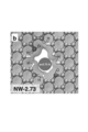
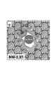
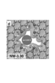
- FIGS. 10 to 15 are model diagrams showing an example of a carbon filter and a rim having flexible nanowindows having different sizes.
- light gray atoms represent carbon (C)
- dark gray atoms represent oxygen (O)
- white atoms represent hydrogen (H).
- NW-x is the van der Waals diameter ⁇ ( ⁇ ) of the nanowindow.
- the van der Waals diameter of the nanowindow of FIG. 10 is 2.57 ⁇ .
- the van der Waals diameters of the nanowindows of FIGS. 11, 12, 13, 14, and 15 are 2.73 ⁇ , 2.97 ⁇ , 3.30 ⁇ , 3.70 ⁇ , and 3.78 ⁇ , respectively.
- x when "NW-x" is displayed is the van der Waals diameter ⁇ ( ⁇ ) of the flexible nanowindow.
- the van der Waals diameter of the flexible nanowindow is , Equal to the maximum diameter of the circle inscribed in the flexible nanowindow.
- selectivity is conversely reduced.
- the flexible nanowindows of FIGS. 14 (NW-3.78) and 15 (NW-3.70) have high transmittance and low separation selectivity.
- the van der Waals diameter of the flexible nanowindow is set to the size of FIG. 13
- the Ar transmission rate is reduced by 50 times as compared with the flexible nanowindow of FIG.
- N 2 / Ar selectivity increased to 20, the effect as a molecular sieve.
- FIG. 16 shows the results obtained by adapting the transmittance of each molecule of oxygen, nitrogen and argon in each model of FIGS. 10 to 15 to the primary model of MD simulation.
- the transmittance (unit: ⁇ s -1 ) shown in FIG. 16 is ⁇ 0.004 ⁇ s -1 , it can be interpreted that the molecule cannot permeate.
- the one capable of achieving both oxygen permeability and selectivity at a high level is that of FIG.
- the oxygen permeation rate constant is 47 ⁇ s -1 , which corresponds to 600 m 3 STP min -1 m -2 .
- the selectivity is greater than 50 times in the O 2 : N 2 separation (1500 times in the O 2 : Ar separation).
- three bar graphs are shown for each size of the nanowindow. Of the three bar graphs, the left side shows O 2 , the center shows N 2 , and the right side shows Ar.
- the partial charge of the heteroatom contained in the functional group formed on the rim induces a strong electrostatic field of GV / m inside the flexible nanowindow.
- the interaction of this electric field with a molecule with a polarized charged center, such as N 2 facilitates the molecular permeation process in the flexible nanowindow.
- the coordinated movement of functional groups on the rim of flexible nanowindows can accelerate the permeation of molecules with polarized charged centers.
- heteroatoms such as hydrogen or oxygen atoms and carbon atoms contained in the functional groups formed on the rim of the flexible nanowindow constitutes the rim of the nanowire, along with the addition of defects in the graphene network. Induces the inhomogeneity of the electron density of atoms.
- These partial charges along the rim induce an electrostatic field on the order of GV / m around the flexible nanowindow.
- This electrostatic field has an attractive interaction with molecules with permanent multipoles, such as the O 2 and N 2 quadrupole moments.
- heteroatoms to be introduced are nitrogen, oxygen, sulfur, phosphorus, chlorine, iodine, bromine, and boron, with oxygen and boron acting particularly effectively.
- the oxygen atom participates in the carbon atom of the flexible nanowindow rim as a donor and the boron atom as an acceptor, giving a heterogeneous electron distribution to the flexible nanowindow rim.
- donor substances such as tetrathiafulvalene (TTF) and acceptor substances such as tetracyanoquinodimethane (TCNQ).
- TTF tetrathiafulvalene
- TCNQ tetracyanoquinodimethane
- it is more direct and effective for the heteroatom to form an edge on the rim of the flexible nanowindow.
- the formation of the flexible nanowindow or the treatment for introducing a functional group or a heteroatom may cause a defect (defect portion) of a carbon atom in the rim of the flexible nanowindow. This has the same effect on the rim of the nanowindow as the introduction of functional groups or heteroatoms.
- the rim of the flexible nanowindow can vibrate and relax during the permeation of molecules. Relaxation of nanowindows such as cyclic polyaromatic molecules can reduce the permeation energy barrier by a factor of 2 to 5 times, although it varies depending on the type of permeate molecule.
- the flexible nanowindow is regarded as having a structure equivalent to that of an aperiodic polycyclic polyaromatic molecule, it is expected that the relaxation effect will be very large. This is because the structure of such aperiodic polycyclic polyaromatic molecules is much stronger than the periodic structure and causes phonon oscillations.
- the introduction of flexibility through rim relaxation into the flexible nanowindow is important because it occurs in parallel with molecular permeation.
- the mechanism by which molecules larger than the van der Waals diameter in the flexible nanowindow penetrate the flexible nanowindow is as follows.
- the electron distribution of the rim or functional group of the flexible nanowindow changes (coordinates) due to the interaction between the electrons of the rim or functional group of the flexible nanowindow and the electrons of the passing molecule.
- the kinetic energy of the penetrating molecule can sufficiently break through the three-dimensional obstacle of the flexible nanowindow rim itself.
- Molecules such as gases are distinguished by the dynamic motion of the rim and the partial charge distribution produced by the heteroatoms, resulting in selective permeation.
- the smallest two-dimensional shapes of O 2 , N 2 , and Ar are 2.99 ⁇ , 3.05 ⁇ , and 3.63 ⁇ , respectively.
- O 2 has a weak coordination with the rim (functional group) of the flexible nanowindow, and relaxation also occurs, but the relaxation effect is small because the coordination is weak (it can pass through a flexible nanowindow smaller than its own size). ).
- N 2 has a large relaxation effect because strong coordination occurs with the rim (functional group) of the flexible nanowindow and strong relaxation occurs (it is easier to pass through flexible nanowindows smaller than its own size than oxygen).
- Ar has no mitigation effect because it does not cooperate with the rim (functional group) of the flexible nanowindow.
- Functional groups such as hydroxyl groups, carboxyl groups and carbonyl groups have several orientations with respect to the flexible nanowindow. Their dynamic orientation changes the shape of the flexible nanowindow and strongly affects the transmission mechanism and its selectivity.
- the rim of the flexible nanowindow is not static, it is breathing and vibrating, and it behaves as if it breathes and relaxes. Similar to the charge distribution, this vibration also causes relaxation by coordinating the rim of the flexible nanowindow and the functional groups formed therein with the permeated molecules.
- Graphene has phonon motion and a unique vibration mode, which causes coordinated vibration in the rim of the nanowindow. These vibrations change the effective size and / or shape of the nanowindow and determine its transmission properties.
- FIG. 17 shows the breathing vibration of the flexible nanowindow shown in FIG. Breathing vibration is vibration that expands and contracts concentrically as if breathing.
- Color gradient rectangle in FIG. 17, N 2 molecule corresponds to the length of time that has passed through the flexible nano window, darker marks correspond to the N 2 center closer to the graphene plane. Therefore, the relationship between the distance of N 2 to graphene and the breathing vibration is shown. Further, the shade of the background shows the distribution of the distances between O1-O2 atoms and O3-O4 atoms shown in FIG. 18, and the darker the color, the higher the frequency of being at that distance. Therefore, FIG. 17 shows the following. That is, the nanowindow of FIG. 18 oscillates with an amplitude of about 0.35 ⁇ with the distance between O1-O2 atoms and the distance between O3-O4 atoms centered on 6.16 ⁇ and 6.54 ⁇ , respectively.
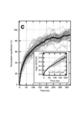
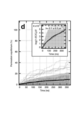
- FIGS. 19 to 22 are diagrams showing the results of MD simulation.
- the thin line shows the execution result of each simulation.
- the dark black line shows the mean of all runs, and the shaded area is the standard deviation each time.
- the inserted subgraph is a linearization of all data, including a linear approximation to the mean.
- the arrow indicates the orientation of the OH functional group containing the O1 atom and the O2 atom
- the black arrow indicates that it is in the graphene plane
- the white arrow indicates the orientation toward the back.
- the broken arrow indicates the orientation toward the front.
- the coordinated operation of the breathing vibration of the rim is not symmetrical.
- the Pearson correlation coefficient between the O1-O2 interatomic distance and the O3-O4 interatomic distance shown in FIG. 20 is ⁇ 0.38. This means that while one direction of the length of the flexible nanowindow rim contracts, one direction perpendicular to it extends.
- the vibration of the flexible nanowindow rim in coordination with this permeate molecule is very similar to that observed in the skeletal dynamics of small pore zeolites called the "window breathing" mode. Permeation of the molecule is effective when the shorter OO interatomic distance (ie, the O1-O2 interatomic distance) exceeds its average.
- the out-of-plane graphene functional groups can also be dynamically switched in their orientation.
- MD simulation of changes in transmittance due to orientation of functional groups eg, hydroxyl groups containing O1, O2, O3 and O4 in FIG. 18
- Flexible NW-3.30 N 2 permeability of MD simulation set through the nano window may be a simulation time of up to 20 nanoseconds, much of the transmission rate (10 ⁇ 5 .mu.s -1) Shows a large fluctuation in.
- H atom bonded to an O atom in the hydroxyl group (N 2 interacts molecules electrostatically) has a freedom of movement in response to rotation of the dihedral angle of the H-O-C-C ..
- the H atom is temporarily locked in the local energy minimum configuration (when quenching the nanowindow skeleton at a specific time).
- both atomic pairs point in the same out-of-graphene direction and in the direction of convergence (see FIG. 25). .. As a result, it behaves like an atomic gate that blocks substances that are trying to penetrate.
- the gate opens and closes in a flexible nanowindow of NW -2.73 or less, which is smaller than in the case of N 2 .
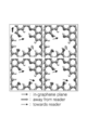
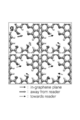
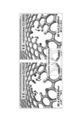
- FIG. 26 and 27 are diagrams for explaining the opening / closing behavior (atomic gate) of the flexible nanowindow.
- the light gray atom represents carbon (C)
- the dark gray atom represents oxygen (O)
- the white atom represents hydrogen (H).
- FIG. 26 shows two examples of a transparent state in which the nanowindow is open. In these examples, the pair of hydrogen atoms at the opposite poles point in opposite directions with respect to the graphene plane.
- the nanowindow of FIG. 26 has a van der Waals diameter of 3.78 ⁇ .
- FIG. 27 shows two examples of a opaque state (atomic gate) in which the flexible nanowindow is closed.
- a pair of hydrogen atoms at opposite poles are oriented in the same direction with respect to the graphene plane.
- the energy difference ⁇ E at the lower left is based on the figure on the left side of FIG. 26 (0).
- this graphene is immersed in, for example, a 1 mol / L nitric acid aqueous solution for 1 hour under a temperature condition of 300 K to introduce a heteroatom. Then, after washing with ultrapure water, it can be transferred to a polycarbonate membrane filter and set in a membrane filter holder to form a gas molecular film. Some edges of the exposed flexible nanowindow are passivated at the -H, -OH or C-OC terminations.
- Applying voltage or irradiating infrared rays is effective for opening and closing the flexible nanowindow using the charge distribution of the rim (functional group).
- the charge distribution of the nanowindow rim can be easily controlled by applying a voltage. For example, when a voltage is applied so that the entire graphene becomes electron-rich, the rim of the nanowindow is filled with electrons and the flexible nanowindow is closed.
- the functional groups When irradiated with electromagnetic waves such as infrared rays, the functional groups rotate or become active due to thermal motion, and the flexible nanowindow is closed. In addition, the rim of the flexible nanowindow is closed due to the effect of phonons generated by electromagnetic wave irradiation. In addition, graphene is weakly irradiated with infrared rays to maintain high molecular permeability, and then infrared irradiation is stopped to maintain the arrangement of functional groups in the open state of the flexible nanowindows for cooling. Can be kept open.
- Flexible nanowindows can permeate molecules larger than their van der Waals diameter.
- O 2 molecules of van der Waals diameter is 3.0 ⁇
- the van der Waals diameter is nano window 2.7 ⁇ in the closed state by the open state of 600m 3 ⁇ min -1 ⁇ m -2 Ultra It is fast and easily transparent.
- the two types of molecules can be separated by the flexible nanowindow.
- the filter unit may have a plurality of pairs of electrodes.
- the filter unit may include at least one of an insulator and a conductive filter.
- Example 1 Single-walled carbon nanotubes (manufactured by Meijo Nanocarbon Co., Ltd., trade name: EC2.0) synthesized by direct injection pyrolysis synthesis (DIPS) were prepared.
- the dispersion of the single-walled carbon nanotubes was spray-coated on one surface of a polycarbonate membrane filter (Isopore, manufactured by Merck & Co., Inc.). After heating to 100 ° C. and drying, a dispersion of single-walled carbon nanotubes was also spray-coated on the other surface of the membrane filter. After drying by heating to 100 ° C., it was further baked at 200 ° C. for 5 minutes. In this way, a film-like carbon filter was formed on both sides of the disk-shaped membrane filter. In this carbon filter, the gaps between the carbon nanotubes constituting the carbon filter function as through holes.
- the membrane filter also functions as an insulator.
- Two disc-shaped platinum meshes were prepared for the electrodes.
- a pair of film-shaped carbon filters formed on both sides of the membrane filter were sandwiched between a pair of platinum meshes to obtain a laminate.
- This laminate was housed in a filter holder to obtain a filter unit.
- This filter unit had a configuration as shown in FIG. 7.
- Example 2 Disc-shaped platinum mesh and carbon paper were prepared one by one for the electrodes. A pair of film-shaped carbon filters formed on both sides of the membrane filter produced in the same procedure as in Example 1 was sandwiched between a platinum mesh and carbon paper to obtain a laminate. This laminate was housed in a filter holder to obtain a filter unit. This filter unit had a configuration as shown in FIG.
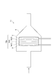
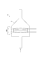
- a filter unit 12 having a structure as shown in FIG. 28 was manufactured by the following procedure.
- a film made of a polyimide resin having a thickness of 10 ⁇ m having through holes having an average opening diameter of 1 ⁇ m was prepared.
- Single-layer graphene (manufactured by Graphene) was transferred to this film and heated in air at 250 ° C. to form flexible nanowindows on the single-layer graphene.
- the transferred single-layer graphene corresponds to the conductive filter 1
- the polyimide film corresponds to the insulator 4.
- a platinum mesh having a disk-shaped outer shape was laminated as a working electrode 2 so as to be in contact with the conductive filter 1.
- the carbon paper was laminated as the counter electrode 3 so as to be in contact with the insulator 4.
- the laminated body 15b was housed in the filter holder 6 so that the working electrode 2 made of platinum mesh was on the upstream side and the counter electrode 3 made of carbon paper was on the downstream side to form the filter unit 12.
- Example 4 Commercially available graphene was heat-treated in air at 600 K for 10 minutes to form flexible nanowindows. This graphene was immersed in a 1 mol / L nitric acid aqueous solution at 300 K for 1 hour to introduce a heteroatom into the flexible nanowindow. After washing with ultrapure water, it was transferred to a polycarbonate membrane filter and set in a membrane filter holder to form a gas molecular film. Some edges of the exposed flexible nanowindow were passivated at the -H, -OH or C-OC terminations. In this way, a conductive filter having a flexible nanowindow in which functional groups having two or more kinds of orientations are bonded was obtained.
Landscapes
- Chemical & Material Sciences (AREA)
- Chemical Kinetics & Catalysis (AREA)
- Engineering & Computer Science (AREA)
- Water Supply & Treatment (AREA)
- Inorganic Chemistry (AREA)
- Health & Medical Sciences (AREA)
- Urology & Nephrology (AREA)
- Materials Engineering (AREA)
- Nanotechnology (AREA)
- Separation Using Semi-Permeable Membranes (AREA)
- Water Treatment By Electricity Or Magnetism (AREA)
- Carbon And Carbon Compounds (AREA)
Priority Applications (5)
| Application Number | Priority Date | Filing Date | Title |
|---|---|---|---|
| US17/612,033 US20220226780A1 (en) | 2019-05-23 | 2019-05-23 | Filter unit and separation device and separation method for fluid |
| EP19929199.8A EP3970838A1 (en) | 2019-05-23 | 2019-05-23 | Filter unit and separation device and separation method for fluid |
| CN201980096542.4A CN114144255A (zh) | 2019-05-23 | 2019-05-23 | 过滤器单元、流体的分离装置以及分离方法 |
| PCT/JP2019/020561 WO2020235111A1 (ja) | 2019-05-23 | 2019-05-23 | フィルターユニット、流体の分離装置及び分離方法 |
| JP2021520033A JP7283805B2 (ja) | 2019-05-23 | 2019-05-23 | 流体の分離装置及び分離方法 |
Applications Claiming Priority (1)
| Application Number | Priority Date | Filing Date | Title |
|---|---|---|---|
| PCT/JP2019/020561 WO2020235111A1 (ja) | 2019-05-23 | 2019-05-23 | フィルターユニット、流体の分離装置及び分離方法 |
Publications (1)
| Publication Number | Publication Date |
|---|---|
| WO2020235111A1 true WO2020235111A1 (ja) | 2020-11-26 |
Family
ID=73459379
Family Applications (1)
| Application Number | Title | Priority Date | Filing Date |
|---|---|---|---|
| PCT/JP2019/020561 Ceased WO2020235111A1 (ja) | 2019-05-23 | 2019-05-23 | フィルターユニット、流体の分離装置及び分離方法 |
Country Status (5)
| Country | Link |
|---|---|
| US (1) | US20220226780A1 (https=) |
| EP (1) | EP3970838A1 (https=) |
| JP (1) | JP7283805B2 (https=) |
| CN (1) | CN114144255A (https=) |
| WO (1) | WO2020235111A1 (https=) |
Cited By (2)
| Publication number | Priority date | Publication date | Assignee | Title |
|---|---|---|---|---|
| US20240058748A1 (en) * | 2021-01-11 | 2024-02-22 | Shenzhen Puremate Technology Co., Ltd. | Device and method for electrochemical degradation of gaseous organic pollutants |
| KR20240049994A (ko) * | 2022-10-11 | 2024-04-18 | 이상천 | 수소가스의 선택적 분리가 가능한 그래핀 필터 및 상기 그래핀 필터가 구비된 수소가스분리시스템 |
Citations (8)
| Publication number | Priority date | Publication date | Assignee | Title |
|---|---|---|---|---|
| JPH01254211A (ja) * | 1988-03-31 | 1989-10-11 | Nitto Denko Corp | 物質分離装置 |
| JP2009073727A (ja) | 2007-08-29 | 2009-04-09 | Olympus Corp | カーボンナノチューブ加工方法及びそれによって加工されたカーボンナノチューブ |
| JP2011520117A (ja) * | 2008-05-06 | 2011-07-14 | コミサリア ア レネルジー アトミック エ オ ゼネルジー アルテルナティブ | 流体から生体分子を分離する装置 |
| US20120211367A1 (en) * | 2011-01-25 | 2012-08-23 | President And Fellows Of Harvard College | Electrochemical carbon nanotube filter and method |
| JP2013536077A (ja) | 2010-08-25 | 2013-09-19 | ロッキード・マーチン・コーポレーション | 穿孔グラフェンによる脱イオンまたは脱塩 |
| JP2014529296A (ja) * | 2011-07-20 | 2014-11-06 | ザ リージェンツ オブ ザ ユニバーシティ オブ カリフォルニア | 2細孔装置 |
| JP2015515369A (ja) * | 2012-03-29 | 2015-05-28 | ロッキード・マーチン・コーポレーション | 濾過または選択的な流体工学的分離及び回収の装置のための調整可能な膜構成 |
| JP2017515131A (ja) * | 2013-05-06 | 2017-06-08 | ツー ポア ガイズ インコーポレイテッド | ナノポアによる標的検出法 |
Family Cites Families (10)
| Publication number | Priority date | Publication date | Assignee | Title |
|---|---|---|---|---|
| JPH04358714A (ja) * | 1991-01-23 | 1992-12-11 | Nissan Motor Co Ltd | エンジンの排気浄化装置 |
| JPH06229224A (ja) * | 1993-02-03 | 1994-08-16 | Isuzu Ceramics Kenkyusho:Kk | ディーゼルパティキュレートフィルタ |
| JP3129591B2 (ja) * | 1993-11-17 | 2001-01-31 | 株式会社いすゞセラミックス研究所 | ディ−ゼルパティキュレ−トフィルタ |
| EP2110168A1 (en) * | 2000-12-01 | 2009-10-21 | Millipore Corporation | Barrier filter with hydrophilic and hydrophobic membrane parts |
| JP5283351B2 (ja) | 2007-05-24 | 2013-09-04 | 学校法人 龍谷大学 | 浄水器 |
| DE102008004237A1 (de) * | 2008-01-14 | 2009-07-16 | Ps Prozesstechnik Gmbh | Verfahren und Vorrichtung zum Filtern |
| WO2010150534A1 (ja) * | 2009-06-23 | 2010-12-29 | クラレケミカル株式会社 | 通液型キャパシタ、脱イオン水の製造方法、及び脱イオン水製造装置 |
| DE102011114400A1 (de) * | 2011-09-22 | 2013-03-28 | Hydac Filtertechnik Gmbh | Filtermaterial |
| KR20150131835A (ko) * | 2014-05-16 | 2015-11-25 | 한국기계연구원 | 도전성 나노 소재가 포함된 다기능 필터 |
| JPWO2019013059A1 (ja) * | 2017-07-14 | 2020-05-07 | 国立大学法人信州大学 | グラフェンのナノウィンドウ構造、グラフェン膜、および高純度ガスの製造方法 |
-
2019
- 2019-05-23 JP JP2021520033A patent/JP7283805B2/ja active Active
- 2019-05-23 WO PCT/JP2019/020561 patent/WO2020235111A1/ja not_active Ceased
- 2019-05-23 EP EP19929199.8A patent/EP3970838A1/en not_active Withdrawn
- 2019-05-23 US US17/612,033 patent/US20220226780A1/en not_active Abandoned
- 2019-05-23 CN CN201980096542.4A patent/CN114144255A/zh active Pending
Patent Citations (8)
| Publication number | Priority date | Publication date | Assignee | Title |
|---|---|---|---|---|
| JPH01254211A (ja) * | 1988-03-31 | 1989-10-11 | Nitto Denko Corp | 物質分離装置 |
| JP2009073727A (ja) | 2007-08-29 | 2009-04-09 | Olympus Corp | カーボンナノチューブ加工方法及びそれによって加工されたカーボンナノチューブ |
| JP2011520117A (ja) * | 2008-05-06 | 2011-07-14 | コミサリア ア レネルジー アトミック エ オ ゼネルジー アルテルナティブ | 流体から生体分子を分離する装置 |
| JP2013536077A (ja) | 2010-08-25 | 2013-09-19 | ロッキード・マーチン・コーポレーション | 穿孔グラフェンによる脱イオンまたは脱塩 |
| US20120211367A1 (en) * | 2011-01-25 | 2012-08-23 | President And Fellows Of Harvard College | Electrochemical carbon nanotube filter and method |
| JP2014529296A (ja) * | 2011-07-20 | 2014-11-06 | ザ リージェンツ オブ ザ ユニバーシティ オブ カリフォルニア | 2細孔装置 |
| JP2015515369A (ja) * | 2012-03-29 | 2015-05-28 | ロッキード・マーチン・コーポレーション | 濾過または選択的な流体工学的分離及び回収の装置のための調整可能な膜構成 |
| JP2017515131A (ja) * | 2013-05-06 | 2017-06-08 | ツー ポア ガイズ インコーポレイテッド | ナノポアによる標的検出法 |
Cited By (3)
| Publication number | Priority date | Publication date | Assignee | Title |
|---|---|---|---|---|
| US20240058748A1 (en) * | 2021-01-11 | 2024-02-22 | Shenzhen Puremate Technology Co., Ltd. | Device and method for electrochemical degradation of gaseous organic pollutants |
| KR20240049994A (ko) * | 2022-10-11 | 2024-04-18 | 이상천 | 수소가스의 선택적 분리가 가능한 그래핀 필터 및 상기 그래핀 필터가 구비된 수소가스분리시스템 |
| KR102699532B1 (ko) * | 2022-10-11 | 2024-08-26 | 이상천 | 수소가스의 선택적 분리가 가능한 그래핀 필터 및 상기 그래핀 필터가 구비된 수소가스분리시스템 |
Also Published As
| Publication number | Publication date |
|---|---|
| JPWO2020235111A1 (https=) | 2020-11-26 |
| JP7283805B2 (ja) | 2023-05-30 |
| US20220226780A1 (en) | 2022-07-21 |
| EP3970838A1 (en) | 2022-03-23 |
| CN114144255A (zh) | 2022-03-04 |
Similar Documents
| Publication | Publication Date | Title |
|---|---|---|
| Jiao et al. | Emerging hydrovoltaic technology based on carbon black and porous carbon materials: A mini review | |
| Kang et al. | 2D laminar membranes for selective water and ion transport | |
| Safaei et al. | Progress and prospects of two-dimensional materials for membrane-based osmotic power generation | |
| Wang et al. | Blue energy conversion from holey-graphene-like membranes with a high density of subnanometer pores | |
| Ali et al. | Logic gates using nanofluidic diodes based on conical nanopores functionalized with polyprotic acid chains | |
| Xiao et al. | Biomimetic solid‐state nanochannels: from fundamental research to practical applications | |
| Zhao et al. | Ion selection of charge-modified large nanopores in a graphene sheet | |
| Sun et al. | Highly selective charge-guided ion transport through a hybrid membrane consisting of anionic graphene oxide and cationic hydroxide nanosheet superlattice units | |
| Sun et al. | Selective ion transport through functionalized graphene membranes based on delicate ion–graphene interactions | |
| Rehman et al. | Graphene-based composite membranes for isotope separation: challenges and opportunities | |
| Aliprandi et al. | Punctured two-dimensional sheets for harvesting blue energy | |
| Lin et al. | Cellulose hydrogel with in-situ confined nanopores for boosting moist-electric conversion | |
| US11278849B2 (en) | Graphene nanowindow structure and method for producing highly pure gas | |
| Yao et al. | Bio-inspired salinity-gradient power generation with UiO-66-NH2 metal-organic framework based composite membrane | |
| Cui et al. | Two-dimensional material-based nanofluidic devices and their applications | |
| WO2020235111A1 (ja) | フィルターユニット、流体の分離装置及び分離方法 | |
| Dong et al. | High-performance osmotic power generators based on the 1D/2D hybrid nanochannel system | |
| Miansari et al. | Graphene-based planar nanofluidic rectifiers | |
| Qian et al. | Biomimetic Janus MXene membrane with bidirectional ion permselectivity for enhanced osmotic effects and iontronic logic control | |
| Madauß et al. | Selective proton transport for hydrogen production using graphene oxide membranes | |
| Li et al. | Improved interfacial ion transport through nanofluidic hybrid membranes based on covalent organic frameworks for osmotic energy generation | |
| Konch et al. | Uphill anion pumping through triangular nanofluidic device of reconstructed layered double hydroxide | |
| Baek et al. | Improvement of vertically aligned carbon nanotube membranes: Desalination potential, flux enhancement and scale-up | |
| Yu et al. | Graphene oxide‐based nanofluidic membranes for reverse electrodialysis that generate electricity from salinity gradients | |
| Lee et al. | Free-standing janus graphene oxide with anisotropic properties for 2D materials as surfactant |
Legal Events
| Date | Code | Title | Description |
|---|---|---|---|
| 121 | Ep: the epo has been informed by wipo that ep was designated in this application |
Ref document number: 19929199 Country of ref document: EP Kind code of ref document: A1 |
|
| ENP | Entry into the national phase |
Ref document number: 2021520033 Country of ref document: JP Kind code of ref document: A |
|
| NENP | Non-entry into the national phase |
Ref country code: DE |
|
| ENP | Entry into the national phase |
Ref document number: 2019929199 Country of ref document: EP Effective date: 20211215 |