WO2020234993A1 - 通知装置、通知方法、プログラム - Google Patents
通知装置、通知方法、プログラム Download PDFInfo
- Publication number
- WO2020234993A1 WO2020234993A1 PCT/JP2019/020085 JP2019020085W WO2020234993A1 WO 2020234993 A1 WO2020234993 A1 WO 2020234993A1 JP 2019020085 W JP2019020085 W JP 2019020085W WO 2020234993 A1 WO2020234993 A1 WO 2020234993A1
- Authority
- WO
- WIPO (PCT)
- Prior art keywords
- information
- sound
- speaker
- sound signal
- notification device
- Prior art date
- Legal status (The legal status is an assumption and is not a legal conclusion. Google has not performed a legal analysis and makes no representation as to the accuracy of the status listed.)
- Ceased
Links
Images


Classifications
-
- H—ELECTRICITY
- H04—ELECTRIC COMMUNICATION TECHNIQUE
- H04R—LOUDSPEAKERS, MICROPHONES, GRAMOPHONE PICK-UPS OR LIKE ACOUSTIC ELECTROMECHANICAL TRANSDUCERS; ELECTRIC HEARING AIDS; PUBLIC ADDRESS SYSTEMS
- H04R1/00—Details of transducers, loudspeakers or microphones
- H04R1/20—Arrangements for obtaining desired frequency or directional characteristics
- H04R1/32—Arrangements for obtaining desired frequency or directional characteristics for obtaining desired directional characteristic only
- H04R1/40—Arrangements for obtaining desired frequency or directional characteristics for obtaining desired directional characteristic only by combining a number of identical transducers
-
- H—ELECTRICITY
- H04—ELECTRIC COMMUNICATION TECHNIQUE
- H04S—STEREOPHONIC SYSTEMS
- H04S7/00—Indicating arrangements; Control arrangements, e.g. balance control
- H04S7/30—Control circuits for electronic adaptation of the sound field
- H04S7/302—Electronic adaptation of stereophonic sound system to listener position or orientation
-
- H—ELECTRICITY
- H04—ELECTRIC COMMUNICATION TECHNIQUE
- H04R—LOUDSPEAKERS, MICROPHONES, GRAMOPHONE PICK-UPS OR LIKE ACOUSTIC ELECTROMECHANICAL TRANSDUCERS; ELECTRIC HEARING AIDS; PUBLIC ADDRESS SYSTEMS
- H04R2203/00—Details of circuits for transducers, loudspeakers or microphones covered by H04R3/00 but not provided for in any of its subgroups
- H04R2203/12—Beamforming aspects for stereophonic sound reproduction with loudspeaker arrays
-
- H—ELECTRICITY
- H04—ELECTRIC COMMUNICATION TECHNIQUE
- H04R—LOUDSPEAKERS, MICROPHONES, GRAMOPHONE PICK-UPS OR LIKE ACOUSTIC ELECTROMECHANICAL TRANSDUCERS; ELECTRIC HEARING AIDS; PUBLIC ADDRESS SYSTEMS
- H04R2499/00—Aspects covered by H04R or H04S not otherwise provided for in their subgroups
- H04R2499/10—General applications
- H04R2499/13—Acoustic transducers and sound field adaptation in vehicles
-
- H—ELECTRICITY
- H04—ELECTRIC COMMUNICATION TECHNIQUE
- H04R—LOUDSPEAKERS, MICROPHONES, GRAMOPHONE PICK-UPS OR LIKE ACOUSTIC ELECTROMECHANICAL TRANSDUCERS; ELECTRIC HEARING AIDS; PUBLIC ADDRESS SYSTEMS
- H04R5/00—Stereophonic arrangements
- H04R5/02—Spatial or constructional arrangements of loudspeakers
-
- H—ELECTRICITY
- H04—ELECTRIC COMMUNICATION TECHNIQUE
- H04R—LOUDSPEAKERS, MICROPHONES, GRAMOPHONE PICK-UPS OR LIKE ACOUSTIC ELECTROMECHANICAL TRANSDUCERS; ELECTRIC HEARING AIDS; PUBLIC ADDRESS SYSTEMS
- H04R5/00—Stereophonic arrangements
- H04R5/04—Circuit arrangements, e.g. for selective connection of amplifier inputs/outputs to loudspeakers, for loudspeaker detection, or for adaptation of settings to personal preferences or hearing impairments
-
- H—ELECTRICITY
- H04—ELECTRIC COMMUNICATION TECHNIQUE
- H04S—STEREOPHONIC SYSTEMS
- H04S2400/00—Details of stereophonic systems covered by H04S but not provided for in its groups
- H04S2400/11—Positioning of individual sound objects, e.g. moving airplane, within a sound field
Definitions
- the present invention relates to a technique for emitting a warning sound in a vehicle.
- Non-Patent Document 1 In the conventional technique, only the type of danger is notified by a warning sound, and the direction in which the danger exists is notified by using a separate image (see Non-Patent Document 1).
- an object of the present invention is to provide a notification technique capable of notifying the direction in which danger exists by sound.
- One aspect of the present invention determines a sound signal corresponding to the type indicated by the type information from information on the type of danger estimated based on the sensor data which is the data acquired by the sensor (hereinafter referred to as type information). From the sound signal determination unit, the sound signal, and information on the danger occurrence direction estimated based on the sensor data (hereinafter referred to as direction information), the driver can perform beam forming in the direction indicated by the direction information.
- a notification device including a sound image forming unit that determines sound image information that is a set of a speaker that emits a sound calling attention, a sound signal that is reproduced by the speaker, and a speaker that reproduces an input sound signal.
- the sound image information includes the speaker and the structure so that the driver perceives that the reflected sound of the sound emitted by the speaker reflected on the structure of the vehicle comes from the direction indicated by the direction information. Is determined based on the positional relationship between the driver and the driver.
- One aspect of the present invention determines a sound signal corresponding to the type indicated by the type information from information on the type of danger estimated based on the sensor data which is the data acquired by the sensor (hereinafter referred to as type information). Fluctuations that generate new direction information by adding direction fluctuations to the direction information from the sound signal determination unit and information on the danger occurrence direction estimated based on the sensor data (hereinafter referred to as direction information).
- direction information Fluctuations that generate new direction information by adding direction fluctuations to the direction information from the sound signal determination unit and information on the danger occurrence direction estimated based on the sensor data.
- a sound image that is a set of a speaker that emits a sound that calls the driver's attention in the direction indicated by the direction information by beam forming from the additional part, the sound signal, and the direction information, and a sound signal that is reproduced by the speaker.
- a notification device including a sound image forming unit that determines information and a speaker that reproduces an input sound signal.
- the sound image information is such that the sound emitted by the speaker comes from the direction indicated by the direction information. It is determined based on the positional relationship between the speaker and the driver so that the data and the driver perceive it.
- One aspect of the present invention determines a sound signal corresponding to the type indicated by the type information from information on the type of danger estimated based on the sensor data which is the data acquired by the sensor (hereinafter referred to as type information). Fluctuations that generate new direction information by adding direction fluctuations to the direction information from the sound signal determination unit and information on the danger occurrence direction estimated based on the sensor data (hereinafter referred to as direction information).
- a sound image that is a set of a speaker that emits a sound that calls the driver's attention in the direction indicated by the direction information by pan control from the additional unit, the sound signal, and the direction information, and a sound signal that is reproduced by the speaker. It includes a sound image forming unit that determines information and a speaker that reproduces an input sound signal.
- the driver can know the direction in which the danger exists by sound.
- the notification device is estimated based on sensor data, which is data acquired by the sensor, based on information on the type of danger (hereinafter referred to as type information) and information on the direction in which the danger occurs (hereinafter referred to as direction information). It emits a sound that calls the driver's attention and notifies the type of danger and the direction in which the danger exists.
- type information information on the type of danger
- direction information information on the direction in which the danger occurs
- FIG. 1 is a block diagram showing the configuration of the notification device 100.
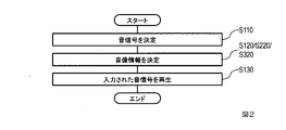
- FIG. 2 is a flowchart showing the operation of the notification device 100.
- the notification device 100 includes a sound signal determination unit 110, a sound image forming unit 120, and a speaker 130.
- the notification device 100 includes N speakers (N is an integer of 2 or more) 130.
- the speaker 130 is a component that reproduces the input sound signal and emits it as sound.
- the sound signal determination unit 110 inputs the type information, determines the sound signal corresponding to the type indicated by the type information from the type information, and outputs the sound signal.
- the notification device 100 records a correspondence table showing the correspondence relationship between the type information and the sound signal in a recording unit (not shown), and the sound signal determination unit 110 uses the correspondence table to record the sound from the type information. The signal may be determined.
- the sound image forming unit 120 receives the sound signal and direction information determined in S110, and uses the direction information to emit a sound that calls the driver's attention in the direction indicated by the direction information (hereinafter, reproduction).
- reproduction By selecting (referred to as a playback sound signal) and generating a sound signal to be reproduced by the reproduction speaker (hereinafter referred to as a reproduction sound signal) from the sound signal, the sound image information which is a set of the reproduction speaker and the reproduction sound signal is determined.
- the reproduced sound signal paired with the sound image information is output to the speaker 130 designated by the sound image information. That is, the sound image forming unit 120 changes the position of the sound image according to the direction in which the danger occurs.
- the sound image is a place of sound that the driver perceives when he / she hears the sound.
- the sound image forming unit 120 may determine the speaker 130 closest to the direction information as the reproduction speaker based on the direction information.
- the speaker 130 designated by the sound image information determined in S120 reproduces a reproduced sound signal as a set based on the sound image information.
- control of the sound image position for calling attention to the driver has been described, but the control of the sound image position for calling attention to the passenger may be used, and attention should be paid to both the driver and the passenger. It may be the control of the sound image position for prompting.
- the danger to be notified may be that occurred in the car.
- the position of the sound image may be controlled according to the relative positional relationship between the notification target person such as the driver or the passenger and the position or direction in which the danger occurs.
- the posture estimation process may be executed from the data acquired by the sensor such as an image or a point cloud to control the position of the sound image.
- the danger that the driver is dozing is detected from the acoustic signal collected by the microphone installed in the car, the driver is dozing from the position or direction where the driver exists based on the passenger to be notified.
- the position of the sound image may be controlled so that the passenger can perceive the sound based on the sound signal corresponding to the above type.
- the driver can know the direction in which the danger exists by sound. By selecting the speaker according to the direction in which the danger exists and emitting sound, the driver can instantly understand the direction. That is, the driver can quickly perform an operation for avoiding danger without checking the screen.
- the notification device 100 controls the sound image by selecting the reproduction speaker. Therefore, the sound image can be created only at the position where the speaker is installed. Therefore, in the notification device 200, the sound image is localized even in a place where the speaker is not installed by reproducing the sound signal based on the ratio calculated in advance by the plurality of speakers according to the direction information (pan control). Is possible. For example, if pan control is performed so that sound is emitted from two speakers at the same time, a sound image can be localized between the two speakers.
- FIG. 1 is a block diagram showing the configuration of the notification device 200.
- FIG. 2 is a flowchart showing the operation of the notification device 200.
- the notification device 200 includes a sound signal determination unit 110, a sound image forming unit 220, and a speaker 130.
- the notification device 200 includes N speakers (N is an integer of 2 or more) 130.
- the notification device 200 differs from the notification device 100 only in that it includes a sound image forming unit 220 instead of the sound image forming unit 120.
- the sound signal determination unit 110 inputs the type information, determines the sound signal corresponding to the type indicated by the type information from the type information, and outputs the sound signal.
- the sound image forming unit 220 receives the sound signal and direction information determined in S110 as inputs, and emits a sound that calls the driver's attention in the direction indicated by the direction information by pan control from the sound signal and direction information.
- Sound image information which is a set of a sounding speaker (hereinafter referred to as a reproduction speaker) and a sound signal reproduced by the speaker (hereinafter referred to as a reproduced sound signal), is determined, and the sound image information is transmitted to the speaker 130 designated by the sound image information. Outputs the reproduced sound signal that is paired with.
- FIG. 3 is a block diagram showing the configuration of the sound image forming unit 220.
- FIG. 4 is a flowchart showing the operation of the sound image forming unit 220.
- the sound image forming unit 220 includes a gain calculation unit 221 and a multiplication unit 222.
- the sound image forming unit 220 includes N multiplication units 222. However, this N is the same number as the number of speakers 130.
- the gain calculation unit 221 receives the direction information as input, calculates the gain used by the multiplication unit 222 corresponding to each of the N speakers 130 from the direction information, and causes the multiplication unit 222 corresponding to each of the speakers 130. Output.
- the gain calculation unit 221 calculates the gain according to the position to be localized based on the relationship between the sound image position during stereo reproduction and the reproduction volume ratio in order to localize the sound image at a desired position.
- the notification device 200 records a correspondence table (not shown) showing the relationship between the sound image localization position and the volume balance of the speaker reproduction, which is obtained in advance in the experiment, and the gain calculation unit 221 records the correspondence table. The gain may be calculated using the correspondence table.
- the multiplication unit 222 takes the sound signal and the gain calculated in S221 as inputs, calculates a reproduction sound signal from the sound signal and the gain, and outputs the sound signal to the speaker 130 corresponding to the multiplication unit 222.
- the speaker 130 designated by the sound image information determined in S120 reproduces a reproduced sound signal as a set based on the sound image information.
- the sound image position may be controlled to call attention to the passenger, or the sound image position may be controlled to call attention to both the driver and the passenger. There may be. Further, as in the first embodiment, the danger to be notified may be caused in the vehicle.
- the driver can know the direction in which the danger exists by sound.
- the driver By emitting warning sounds from multiple speakers in a balanced manner according to the direction in which the danger exists, it is possible to localize the sound image at a position where no speakers are installed, so that the driver can understand the direction more accurately. Become.
- the notification device 100 controls the sound image by selecting the reproduction speaker. Therefore, the sound image can be created only at the position where the speaker is installed. Further, the notification device 200 reproduces a sound signal based on a ratio calculated in advance by a plurality of speakers. Therefore, the sound image cannot be localized at a position other than between the speakers. Therefore, in the notification device 300, by beamforming according to the direction information, it is possible to localize the sound image even at a position other than between the speakers.
- multiple speakers in front of the driver who is the listener, are used to form a beam so that the sound pressure near the driver's right ear is high and the sound pressure in the left ear is low (ie, beam Forming), a sound image can be formed on the right side of the driver.
- FIG. 1 is a block diagram showing a configuration of the notification device 300.
- FIG. 2 is a flowchart showing the operation of the notification device 300.
- the notification device 300 includes a sound signal determination unit 110, a sound image forming unit 320, and a speaker 130.
- the notification device 300 includes N speakers (N is an integer of 2 or more) 130.
- the notification device 300 differs from the notification device 100 only in that it includes a sound image forming unit 320 instead of the sound image forming unit 120.
- the sound signal determination unit 110 inputs the type information, determines the sound signal corresponding to the type indicated by the type information from the type information, and outputs the sound signal.
- the sound image forming unit 320 receives the sound signal and direction information determined in S110 as input, and emits a sound that calls the driver's attention in the direction indicated by the direction information by beam forming from the sound signal and direction information.
- Sound image information which is a set of a sounding speaker (hereinafter referred to as a reproduction speaker) and a sound signal reproduced by the speaker (hereinafter referred to as a reproduced sound signal), is determined, and the sound image information is transmitted to the speaker 130 designated by the sound image information. Outputs the reproduced sound signal that is paired with.
- Method 1 Method using a filter
- the sound pressure is increased as much as possible by using the transmission characteristics from each speaker to the position where the sound pressure is desired to be increased and the transmission characteristics from each speaker to the position where the sound pressure is desired to be decreased.
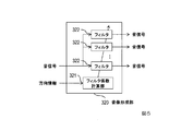
- FIG. 5 is a block diagram showing the configuration of the sound image forming unit 320.
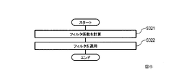
- FIG. 6 is a flowchart showing the operation of the sound image forming unit 320.
- the sound image forming unit 320 includes a filter coefficient calculation unit 321 and a filter 322.
- the sound image forming unit 320 includes N filters 322. However, this N is the same number as the number of speakers 130.
- the filter coefficient calculation unit 321 receives the direction information as input, calculates the filter coefficient used in the filter 322 corresponding to each of the N speakers 130 from the direction information, and causes the filter 322 corresponding to each of the speakers 130. Output.
- the filter 322 takes the sound signal and the filter coefficient calculated in S321 as inputs, calculates a reproduction sound signal from the sound signal and the filter coefficient, and outputs the sound signal to the speaker 130 corresponding to the filter 322.
- Method 2 Method using delay In this method, the amount of delay given to the sound signal reproduced by each speaker is calculated so that the delay at the position where the sound pressure is desired to be increased is the same.
- FIG. 7 is a block diagram showing the configuration of the sound image forming unit 320.
- FIG. 8 is a flowchart showing the operation of the sound image forming unit 320.
- the sound image forming unit 320 includes a delay amount calculation unit 326, a gain calculation unit 327, a delay amount application unit 328, and a multiplication unit 329.
- the sound image forming unit 320 includes N delay amount application units 328 and N multiplication units 329. However, this N is the same number as the number of speakers 130.
- the delay amount calculation unit 326 receives the direction information as input, calculates the delay amount used by the delay amount application unit 328 corresponding to each of the N speakers 130 from the direction information, and corresponds to each of the speakers 130. Output to the delay amount application unit 328.
- the gain calculation unit 327 takes the direction information as an input, calculates the gain used by the multiplication unit 329 corresponding to each of the N speakers 130 from the direction information, and causes the multiplication unit 329 corresponding to each of the speakers 130. Output.
- the delay amount application unit 328 takes the sound signal and the delay amount calculated in S326 as inputs, calculates a delayed sound signal having a delay corresponding to the delay amount from the sound signal and the delay amount, and applies the delay amount. Output to the multiplication unit 329 corresponding to the unit 328.
- the delay amount application unit 328 can be configured by using the FIFO buffer 3281 and the all-pass filter 3382, for example, as shown in FIG.
- the multiplication unit 329 takes the delayed sound signal calculated in S328 and the gain calculated in S327 as inputs, calculates the reproduction sound signal from the delayed sound signal and the gain, and the speaker 130 corresponding to the multiplication unit 329. Output to.
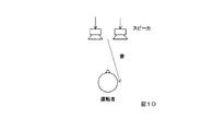
- the sound image forming unit 320 has a positional relationship between the speaker and the driver so that the driver perceives that the sound emitted by the speaker comes from the direction indicated by the direction information.
- the sound image information may be determined based on the above, or as shown in FIG. 11, the reflected sound that the sound emitted from the speaker is reflected on the structure of the vehicle comes from the direction indicated by the direction information.
- the sound image information may be determined based on the positional relationship between the speaker, the structure, and the driver so that the driver perceives. In the latter case, for example, the sound is reflected by the window glass, and beamforming is performed so that the sound can be heard from that direction.
- the position of the driver can be, for example, the position of the seat in which the driver is seated.
- the speaker 130 designated by the sound image information determined in S120 reproduces a reproduced sound signal as a set based on the sound image information.
- the sound image position may be controlled to call attention to the passenger, or the sound image position may be controlled to call attention to both the driver and the passenger. There may be. Further, as in the first embodiment, the danger to be notified may have occurred in the vehicle.
- the driver can know the direction in which the danger exists by sound.
- a beam according to the direction in which the danger exists and emitting a warning sound, sound image localization is possible in all directions even if the speaker is not installed so as to surround the driver, and the driver can be localized. Will be able to understand the direction more accurately.
- the notification device 101/201/301 will be described in which the notification device 100/200/300 is added with a component for adding fluctuations that change the position of the sound image with time. This makes it possible to emphasize the sense of localization of the sound image.
- FIG. 12 is a block diagram showing the configuration of the notification device 101/201/301.
- FIG. 13 is a flowchart showing the operation of the notification device 101/201/301.
- the notification device 101/201/301 includes a sound signal determination unit 110, a fluctuation addition unit 415, a sound image forming unit 120/220/320, and a speaker 130.
- the notification device 101/201/301 includes N speakers (N is an integer of 2 or more) 130.
- the notification device 101/201/301 is different from the notification device 100/200/300 only in that it further includes the fluctuation addition unit 415.
- the fluctuation addition unit 415 inputs the direction information, and generates and outputs the information obtained by adding the fluctuation of the direction to the direction information from the direction information as new direction information.
- the fluctuation of the direction means that the direction is changed with time
- the newly generated direction information is the direction information that changes the direction with time.
- a person is sensitive to rapid changes in the sound image from side to side, and the perception of the sound image is improved. Therefore, it is advisable to give fluctuations to change the direction of the sound image to the left and right several times per second. For example, it is advisable to give a fluctuation of a 3 Hz sine wave so that the sound image position changes in the horizontal direction.
- the driver can know the direction in which the danger exists by sound. By emitting a fluctuating warning sound, the sense of localization of the sound image can be emphasized, and the driver can more accurately understand the direction in which the danger exists.
- the device of the present invention is, for example, as a single hardware entity, an input unit to which a keyboard or the like can be connected, an output unit to which a liquid crystal display or the like can be connected, and a communication device (for example, a communication cable) capable of communicating outside the hardware entity.
- Communication unit to which can be connected CPU (Central Processing Unit, cache memory, registers, etc.), RAM and ROM as memory, external storage device as hard hardware, and input, output, and communication units of these , CPU, RAM, ROM, has a connecting bus so that data can be exchanged between external storage devices.
- a device (drive) or the like capable of reading and writing a recording medium such as a CD-ROM may be provided in the hardware entity.
- a general-purpose computer or the like is a physical entity equipped with such hardware resources.
- the external storage device of the hardware entity stores the program required to realize the above-mentioned functions and the data required for processing this program (not limited to the external storage device, for example, reading a program). It may be stored in a ROM, which is a dedicated storage device). Further, the data obtained by the processing of these programs is appropriately stored in a RAM, an external storage device, or the like.
- each program stored in the external storage device (or ROM, etc.) and the data necessary for processing each program are read into the memory as needed, and are appropriately interpreted, executed, and processed by the CPU. ..
- the CPU realizes a predetermined function (each configuration requirement represented by the above, ... Department, ... means, etc.).
- the processing function in the hardware entity (device of the present invention) described in the above embodiment is realized by a computer
- the processing content of the function that the hardware entity should have is described by a program. Then, by executing this program on the computer, the processing function in the hardware entity is realized on the computer.
- the program that describes this processing content can be recorded on a computer-readable recording medium.
- the computer-readable recording medium may be, for example, a magnetic recording device, an optical disk, a photomagnetic recording medium, a semiconductor memory, or the like.
- a hard disk device, a flexible disk, a magnetic tape, etc. as a magnetic recording device
- a DVD Digital Versatile Disc
- DVD-RAM Random Access Memory
- CD-ROM Compact Disc Read Only
- Memory CD-R (Recordable) / RW (ReWritable), etc.
- MO Magnetto-Optical disc
- EP-ROM Electroically Erasable and Programmable-Read Only Memory
- semiconductor memory can be used.
- this program is carried out, for example, by selling, transferring, renting, etc., a portable recording medium such as a DVD or CD-ROM on which the program is recorded.
- the program may be stored in the storage device of the server computer, and the program may be distributed by transferring the program from the server computer to another computer via a network.
- a computer that executes such a program first stores, for example, a program recorded on a portable recording medium or a program transferred from a server computer in its own storage device. Then, when the process is executed, the computer reads the program stored in its own storage device and executes the process according to the read program. Further, as another execution form of this program, a computer may read the program directly from a portable recording medium and execute processing according to the program, and further, the program is transferred from the server computer to this computer. It is also possible to execute the process according to the received program one by one each time. In addition, the above processing is executed by a so-called ASP (Application Service Provider) type service that realizes the processing function only by the execution instruction and result acquisition without transferring the program from the server computer to this computer. May be.
- the program in this embodiment includes information used for processing by a computer and equivalent to the program (data that is not a direct command to the computer but has a property of defining the processing of the computer, etc.).
- the hardware entity is configured by executing a predetermined program on the computer, but at least a part of these processing contents may be realized in terms of hardware.
Landscapes
- Health & Medical Sciences (AREA)
- Otolaryngology (AREA)
- Physics & Mathematics (AREA)
- Engineering & Computer Science (AREA)
- Acoustics & Sound (AREA)
- Signal Processing (AREA)
- Stereophonic System (AREA)
- Traffic Control Systems (AREA)
Priority Applications (3)
| Application Number | Priority Date | Filing Date | Title |
|---|---|---|---|
| JP2021519935A JPWO2020234993A1 (https=) | 2019-05-21 | 2019-05-21 | |
| US17/612,205 US11778369B2 (en) | 2019-05-21 | 2019-05-21 | Notification apparatus, notification method, and program |
| PCT/JP2019/020085 WO2020234993A1 (ja) | 2019-05-21 | 2019-05-21 | 通知装置、通知方法、プログラム |
Applications Claiming Priority (1)
| Application Number | Priority Date | Filing Date | Title |
|---|---|---|---|
| PCT/JP2019/020085 WO2020234993A1 (ja) | 2019-05-21 | 2019-05-21 | 通知装置、通知方法、プログラム |
Publications (1)
| Publication Number | Publication Date |
|---|---|
| WO2020234993A1 true WO2020234993A1 (ja) | 2020-11-26 |
Family
ID=73459084
Family Applications (1)
| Application Number | Title | Priority Date | Filing Date |
|---|---|---|---|
| PCT/JP2019/020085 Ceased WO2020234993A1 (ja) | 2019-05-21 | 2019-05-21 | 通知装置、通知方法、プログラム |
Country Status (3)
| Country | Link |
|---|---|
| US (1) | US11778369B2 (https=) |
| JP (1) | JPWO2020234993A1 (https=) |
| WO (1) | WO2020234993A1 (https=) |
Citations (3)
| Publication number | Priority date | Publication date | Assignee | Title |
|---|---|---|---|---|
| JPH04259879A (ja) * | 1991-02-14 | 1992-09-16 | Nissan Motor Co Ltd | 立体音場警報装置 |
| JP2013173430A (ja) * | 2012-02-24 | 2013-09-05 | Denso Corp | 車両用音出力装置 |
| JP2017068641A (ja) * | 2015-09-30 | 2017-04-06 | ヤマハ株式会社 | 障害物報知装置 |
Family Cites Families (13)
| Publication number | Priority date | Publication date | Assignee | Title |
|---|---|---|---|---|
| JPH07159190A (ja) * | 1993-12-09 | 1995-06-23 | Zanabui Informatics:Kk | 車載用音響装置統合システム |
| US6097285A (en) * | 1999-03-26 | 2000-08-01 | Lucent Technologies Inc. | Automotive auditory feedback of changing conditions outside the vehicle cabin |
| JP2004271983A (ja) | 2003-03-10 | 2004-09-30 | Yamaha Corp | 警報音定位装置 |
| JP2006005868A (ja) | 2004-06-21 | 2006-01-05 | Denso Corp | 車両用報知音出力装置及びプログラム |
| US7649444B1 (en) * | 2005-12-13 | 2010-01-19 | Nvidia Corporation | Positional audio cues for an vehicle indicator system |
| JP2008143381A (ja) | 2006-12-11 | 2008-06-26 | Toyota Motor Corp | 車両用警告システム、車両用警告システムの警告方法 |
| US8981942B2 (en) * | 2012-12-17 | 2015-03-17 | State Farm Mutual Automobile Insurance Company | System and method to monitor and reduce vehicle operator impairment |
| JP6564576B2 (ja) * | 2015-02-16 | 2019-08-21 | 修一 田山 | 自動車における近接体警報知装置 |
| EP3319343A1 (en) * | 2016-11-08 | 2018-05-09 | Harman Becker Automotive Systems GmbH | Vehicle sound processing system |
| US9896031B1 (en) * | 2017-01-03 | 2018-02-20 | Ford Global Technologies, Llc | Spatial auditory alerts for a vehicle |
| KR20180090644A (ko) | 2017-02-03 | 2018-08-13 | 한국전자통신연구원 | 운전자 및 차량 간의 상호 작용을 위한 장치 및 그 방법 |
| JP6940320B2 (ja) * | 2017-07-10 | 2021-09-22 | パイオニア株式会社 | 音出力装置 |
| CN111079474A (zh) * | 2018-10-19 | 2020-04-28 | 上海商汤智能科技有限公司 | 乘客状态分析方法和装置、车辆、电子设备、存储介质 |
-
2019
- 2019-05-21 WO PCT/JP2019/020085 patent/WO2020234993A1/ja not_active Ceased
- 2019-05-21 US US17/612,205 patent/US11778369B2/en active Active
- 2019-05-21 JP JP2021519935A patent/JPWO2020234993A1/ja active Pending
Patent Citations (3)
| Publication number | Priority date | Publication date | Assignee | Title |
|---|---|---|---|---|
| JPH04259879A (ja) * | 1991-02-14 | 1992-09-16 | Nissan Motor Co Ltd | 立体音場警報装置 |
| JP2013173430A (ja) * | 2012-02-24 | 2013-09-05 | Denso Corp | 車両用音出力装置 |
| JP2017068641A (ja) * | 2015-09-30 | 2017-04-06 | ヤマハ株式会社 | 障害物報知装置 |
Also Published As
| Publication number | Publication date |
|---|---|
| US20220225019A1 (en) | 2022-07-14 |
| US11778369B2 (en) | 2023-10-03 |
| JPWO2020234993A1 (https=) | 2020-11-26 |
Similar Documents
| Publication | Publication Date | Title |
|---|---|---|
| NL1029844C2 (nl) | Werkwijze, inrichting en computerleesbaar medium om een 2-kanaalvirtueelgeluid weer te geven gebaseerd op de luisteraarpositie. | |
| US10063988B2 (en) | Vehicle sound processing system | |
| KR100943215B1 (ko) | 음장 합성을 이용한 입체 음장 재생 장치 및 그 방법 | |
| WO2012140525A1 (en) | Translating user interface sounds into 3d audio space | |
| US10382879B1 (en) | Virtual sound field | |
| Brinkmann et al. | Audio quality assessment for virtual reality | |
| JP6690007B2 (ja) | 処理装置、サーバ装置、出力方法及びプログラム | |
| CN109195072B (zh) | 基于汽车的音频播放控制系统及方法 | |
| WO2020234993A1 (ja) | 通知装置、通知方法、プログラム | |
| CN118749060A (zh) | 用于测试具有声音传感器的驾驶员辅助系统的试验台系统 | |
| WO2021048893A1 (ja) | 集音放音装置、集音放音方法、およびプログラム | |
| US20210006923A1 (en) | Computing system for binaural ambisonics decoding | |
| CN114902695A (zh) | 信号处理装置和方法、声学再现装置和程序 | |
| JP7803351B2 (ja) | 雑音抑圧装置、雑音抑圧方法、プログラム | |
| EP3813384B1 (en) | Sound collection/loudspeaker device, method therefor, and program | |
| CN116935684A (zh) | 处理方法、车载设备及计算机存储介质 | |
| JP7688703B2 (ja) | 触覚フィードバックに基づく超低周波音響効果補償システム及び方法、記憶媒体 | |
| US11922921B1 (en) | Systems and methods for comparing acoustic properties of environments and audio equipment | |
| JP2020036304A (ja) | 信号処理方法及び信号処理装置 | |
| CN119012104A (zh) | 汽车功放的音频测试系统及音频测试方法 | |
| JP2007329821A (ja) | 音響特性補正装置 | |
| WO2019163013A1 (ja) | 音声信号処理装置、音声調整方法及びプログラム | |
| JP2009027331A (ja) | 音場再現システム | |
| WO2024024053A1 (ja) | 伝達特性補正装置、伝達特性補正方法、プログラム | |
| CN116546417A (zh) | 一种车内提示音的播放方法、系统、设备、介质和汽车 |
Legal Events
| Date | Code | Title | Description |
|---|---|---|---|
| 121 | Ep: the epo has been informed by wipo that ep was designated in this application |
Ref document number: 19929207 Country of ref document: EP Kind code of ref document: A1 |
|
| ENP | Entry into the national phase |
Ref document number: 2021519935 Country of ref document: JP Kind code of ref document: A |
|
| NENP | Non-entry into the national phase |
Ref country code: DE |
|
| 122 | Ep: pct application non-entry in european phase |
Ref document number: 19929207 Country of ref document: EP Kind code of ref document: A1 |