WO2020226115A1 - 伝熱部材及び冷却システム - Google Patents
伝熱部材及び冷却システム Download PDFInfo
- Publication number
- WO2020226115A1 WO2020226115A1 PCT/JP2020/018220 JP2020018220W WO2020226115A1 WO 2020226115 A1 WO2020226115 A1 WO 2020226115A1 JP 2020018220 W JP2020018220 W JP 2020018220W WO 2020226115 A1 WO2020226115 A1 WO 2020226115A1
- Authority
- WO
- WIPO (PCT)
- Prior art keywords
- refrigerant
- heat
- transfer member
- heat transfer
- boiling
- Prior art date
- Legal status (The legal status is an assumption and is not a legal conclusion. Google has not performed a legal analysis and makes no representation as to the accuracy of the status listed.)
- Ceased
Links
Images




Classifications
-
- C—CHEMISTRY; METALLURGY
- C09—DYES; PAINTS; POLISHES; NATURAL RESINS; ADHESIVES; COMPOSITIONS NOT OTHERWISE PROVIDED FOR; APPLICATIONS OF MATERIALS NOT OTHERWISE PROVIDED FOR
- C09K—MATERIALS FOR MISCELLANEOUS APPLICATIONS, NOT PROVIDED FOR ELSEWHERE
- C09K5/00—Heat-transfer, heat-exchange or heat-storage materials, e.g. refrigerants; Materials for the production of heat or cold by chemical reactions other than by combustion
- C09K5/02—Materials undergoing a change of physical state when used
- C09K5/04—Materials undergoing a change of physical state when used the change of state being from liquid to vapour or vice versa
- C09K5/048—Boiling liquids as heat transfer materials
-
- F—MECHANICAL ENGINEERING; LIGHTING; HEATING; WEAPONS; BLASTING
- F28—HEAT EXCHANGE IN GENERAL
- F28D—HEAT-EXCHANGE APPARATUS, NOT PROVIDED FOR IN ANOTHER SUBCLASS, IN WHICH THE HEAT-EXCHANGE MEDIA DO NOT COME INTO DIRECT CONTACT
- F28D15/00—Heat-exchange apparatus with the intermediate heat-transfer medium in closed tubes passing into or through the conduit walls ; Heat-exchange apparatus employing intermediate heat-transfer medium or bodies
- F28D15/02—Heat-exchange apparatus with the intermediate heat-transfer medium in closed tubes passing into or through the conduit walls ; Heat-exchange apparatus employing intermediate heat-transfer medium or bodies in which the medium condenses and evaporates, e.g. heat pipes
- F28D15/04—Heat-exchange apparatus with the intermediate heat-transfer medium in closed tubes passing into or through the conduit walls ; Heat-exchange apparatus employing intermediate heat-transfer medium or bodies in which the medium condenses and evaporates, e.g. heat pipes with tubes having a capillary structure
- F28D15/046—Heat-exchange apparatus with the intermediate heat-transfer medium in closed tubes passing into or through the conduit walls ; Heat-exchange apparatus employing intermediate heat-transfer medium or bodies in which the medium condenses and evaporates, e.g. heat pipes with tubes having a capillary structure characterised by the material or the construction of the capillary structure
-
- H—ELECTRICITY
- H05—ELECTRIC TECHNIQUES NOT OTHERWISE PROVIDED FOR
- H05K—PRINTED CIRCUITS; CASINGS OR CONSTRUCTIONAL DETAILS OF ELECTRIC APPARATUS; MANUFACTURE OF ASSEMBLAGES OF ELECTRICAL COMPONENTS
- H05K7/00—Constructional details common to different types of electric apparatus
- H05K7/20—Modifications to facilitate cooling, ventilating, or heating
- H05K7/2029—Modifications to facilitate cooling, ventilating, or heating using a liquid coolant with phase change in electronic enclosures
- H05K7/20309—Evaporators
-
- H—ELECTRICITY
- H05—ELECTRIC TECHNIQUES NOT OTHERWISE PROVIDED FOR
- H05K—PRINTED CIRCUITS; CASINGS OR CONSTRUCTIONAL DETAILS OF ELECTRIC APPARATUS; MANUFACTURE OF ASSEMBLAGES OF ELECTRICAL COMPONENTS
- H05K7/00—Constructional details common to different types of electric apparatus
- H05K7/20—Modifications to facilitate cooling, ventilating, or heating
- H05K7/2029—Modifications to facilitate cooling, ventilating, or heating using a liquid coolant with phase change in electronic enclosures
- H05K7/20336—Heat pipes, e.g. wicks or capillary pumps
-
- H—ELECTRICITY
- H10—SEMICONDUCTOR DEVICES; ELECTRIC SOLID-STATE DEVICES NOT OTHERWISE PROVIDED FOR
- H10W—GENERIC PACKAGES, INTERCONNECTIONS, CONNECTORS OR OTHER CONSTRUCTIONAL DETAILS OF DEVICES COVERED BY CLASS H10
- H10W40/00—Arrangements for thermal protection or thermal control
- H10W40/70—Fillings or auxiliary members in containers or in encapsulations for thermal protection or control
- H10W40/73—Fillings or auxiliary members in containers or in encapsulations for thermal protection or control for cooling by change of state
-
- H—ELECTRICITY
- H10—SEMICONDUCTOR DEVICES; ELECTRIC SOLID-STATE DEVICES NOT OTHERWISE PROVIDED FOR
- H10W—GENERIC PACKAGES, INTERCONNECTIONS, CONNECTORS OR OTHER CONSTRUCTIONAL DETAILS OF DEVICES COVERED BY CLASS H10
- H10W72/00—Interconnections or connectors in packages
-
- F—MECHANICAL ENGINEERING; LIGHTING; HEATING; WEAPONS; BLASTING
- F28—HEAT EXCHANGE IN GENERAL
- F28F—DETAILS OF HEAT-EXCHANGE AND HEAT-TRANSFER APPARATUS, OF GENERAL APPLICATION
- F28F2200/00—Prediction; Simulation; Testing
- F28F2200/005—Testing heat pipes
-
- F—MECHANICAL ENGINEERING; LIGHTING; HEATING; WEAPONS; BLASTING
- F28—HEAT EXCHANGE IN GENERAL
- F28F—DETAILS OF HEAT-EXCHANGE AND HEAT-TRANSFER APPARATUS, OF GENERAL APPLICATION
- F28F2260/00—Heat exchangers or heat exchange elements having special size, e.g. microstructures
Definitions
- the present invention relates to a heat transfer member and a cooling system.
- Equipment with a large calorific value such as air conditioners, chillers, boilers, and heat engine generators may have a cooling system that utilizes the phase change of the refrigerant such as a boiling cooler.
- this type of cooling system may be used for cooling semiconductor parts having a high heat generation density and electronic devices used in data centers.
- fluorocarbon having a boiling point lower than that of water is often used as a refrigerant.
- fluorocarbon has a high warming coefficient
- a refrigerant that replaces fluorocarbon is required from the viewpoint of reducing the environmental load.
- Patent Document 1 a technique has been proposed in which a liquid having a small environmental load and a low boiling point, such as ethanol, is used as a refrigerant (for example, Patent Document 1).
- the present invention has been made in view of this background, and an object of the present invention is to provide a heat transfer member and a cooling system capable of increasing cooling efficiency by using a refrigerant having a low environmental load.
- the heat transfer member configured to be used in a cooling system using alcohol as a refrigerant.
- the heat transfer member is A heat receiving surface configured to receive heat from the heating element, It has a heat radiating surface configured to dissipate the heat received on the heat receiving surface to the refrigerant.
- the heat radiating surface is a heat transfer member having a plurality of pores having an average pore diameter of 5 nm or more and 1000 nm or less.
- Another aspect of the present invention is a cooling system including the heat transfer member of the above aspect and the refrigerant.
- the heat transfer member has a plurality of pores having an average pore diameter of 5 nm or more and 1000 nm or less on the heat radiating surface that exchanges heat with the refrigerant.
- the average pore diameter of the pores provided on the heat radiating surface is in the optimum range for the specific refrigerant. Therefore, the heat transfer member can form a large number of bubbles in the pores when the refrigerant is placed in a superheated state, and further, the bubbles grown in the pores are quickly removed from the pores. Can be separated. Therefore, the heat transfer member can generate a large number of fine bubbles from the pores immediately after the refrigerant boils. As a result, the heat transfer coefficient on the heat dissipation surface can be improved, and thus the cooling performance can be improved.
- the heat transfer member it is possible to provide a heat transfer member and a cooling system capable of increasing the cooling efficiency by using a refrigerant having a low environmental load.
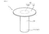
- FIG. 1 is a perspective view of the heat transfer member according to the first embodiment.
- FIG. 2 is a schematic view of a heat radiating surface in the heat transfer member of the first embodiment.
- FIG. 3 is a cross-sectional view showing a main part of an experimental device for a subcool pool boiling experiment used in Example 1.
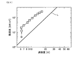
- FIG. 4 is a boiling curve in a subcool pool boiling experiment using the heat transfer member of Example 1.
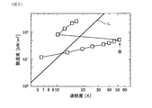
- FIG. 5 is a boiling curve in a subcool pool boiling experiment using the heat transfer member of Example 2.
- FIG. 6 is a plan view of the heat radiating surface of the heat transfer member according to the third embodiment.
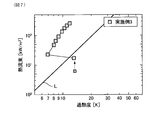
- FIG. 7 is a boiling curve in a subcool pool boiling experiment using the heat transfer member of Example 3.
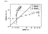
- FIG. 8 is a boiling curve in a subcool pool boiling experiment using the heat transfer members of Examples 4 and 5.
- FIG. 9 is a boiling curve in a subcool pool boiling experiment using the heat transfer members of Examples 6 and 7.
- the heat transfer member can be configured as, for example, a pipe used for a heat pipe, a heat sink, or the like.
- the material of the heat transfer member is not particularly limited, but from the viewpoint of further improving the cooling performance, the heat transfer member is composed of a substance having high thermal conductivity such as copper, copper alloy, aluminum, and aluminum alloy. It is preferable to have.
- the heat transfer member has a heat receiving surface configured to receive heat from a heating element and a heat radiating surface configured to contact the refrigerant and dissipate the heat received on the heat receiving surface to the refrigerant. And have. Further, the heat radiating surface is provided with a plurality of pores having an average pore diameter in the specific range. The pores may be provided on the entire surface of the heat radiating surface, or may be provided only in a part of the region. From the viewpoint of improving the cooling performance of the heat transfer member, the heat radiating surface is preferably arranged on the back surface of the heat receiving surface.
- the average pore diameter of the pores is 5 nm or more and 1000 nm or less.
- the average pore diameter of the pores is 5 nm or more and 1000 nm or less.
- the refrigerant can be supplied into the pores and the next bubbles can be formed.
- a large number of fine bubbles can be generated from the pores, the heat transfer coefficient at the time of boiling can be improved, and the cooling performance can be improved.
- the average pore diameter of the pores is preferably 10 nm or more and 1000 nm or less, more preferably 10 nm or more and 700 nm or less, further preferably 10 nm or more and 500 nm or less, and 10 nm or more. It is particularly preferably 200 nm or less.
- the average pore diameter of the pores can be calculated by the following method. First, the heat radiation surface is observed using a scanning electron microscope (that is, SEM), and an SEM image of the pores is obtained. The magnification of the SEM is not particularly limited, but it is preferable to set it so that a plurality of pores are included in the visual field. Next, the circle-equivalent diameter of each pore present in the obtained SEM image is calculated. Then, the arithmetic mean value of these circle-equivalent diameters may be used as the average pore diameter of the pores. The number of pores used to calculate the average pore diameter of the pores is not particularly limited, but may be, for example, 10 or more.
- pores can be formed using techniques such as photolithography, ion etching, and nanoimprint. Further, for example, when the heat transfer member is made of aluminum or an aluminum alloy, pores can be easily formed on the surface of the heat transfer member by performing anodizing treatment.
- the average depth of the pores is preferably 0.05 ⁇ m or more and 10 ⁇ m or less.
- the average depth of the pores By setting the average depth of the pores to 0.05 ⁇ m or more, the effect of promoting the formation of bubbles by the pores can be further enhanced. Further, by setting the average depth of the pores to 10 ⁇ m or less, the refrigerant can be more quickly supplied into the pores after the bubbles are desorbed. As a result, the cooling performance can be further improved by setting the depth of the pores within the specific range. From the viewpoint of further enhancing the above-mentioned effects, the average depth of the pores is preferably 0.1 ⁇ m or more and 10 ⁇ m or less.
- the average depth of the pores can be calculated by the following method.
- the method of exposing the cross section is not particularly limited. For example, by bending the heat transfer member in a V shape, a crack can be formed to expose the cross section.
- the magnification of the SEM is not particularly limited, but it is preferable to set it so that a plurality of pores are included in the visual field.
- the depth of each pore existing in the obtained SEM image that is, the distance from the heat dissipation surface to the bottom of the pore is calculated.
- the arithmetic mean value of the distances of these pores may be set as the average depth of the pores.
- the number of pores used to calculate the average depth of the pores is not particularly limited, but may be, for example, three or more.
- the heat radiating surface has a parent refrigerant portion having a contact angle with ethanol of 40 ° or less.
- the refrigerant can be heated more efficiently in the parent refrigerant section. As a result, the generation of bubbles can be further promoted and the cooling efficiency can be improved.
- the arrangement of the parent refrigerant portion on the heat dissipation surface can take various aspects.
- the entire surface of the heat radiating surface may be the parent refrigerant portion, or a part of the heat radiating surface may be the parent refrigerant portion.
- the number of parent refrigerant portions on the heat radiating surface may be one or two or more.
- the parent refrigerant portion may be arranged in a portion having pores on the heat radiating surface, or may be arranged in a portion having no pores. From the viewpoint of surely achieving the effect of promoting the generation of bubbles, it is preferable that the parent refrigerant portion is arranged in the portion having pores on the heat radiation surface.
- the heat radiating surface is arranged adjacent to the parent refrigerant portion and further has a sparse refrigerant portion having a contact angle with ethanol larger than that of the parent refrigerant portion.
- a portion in contact with alcohol in the liquid phase and a portion in contact with bubbles, that is, a portion in contact with the vapor of alcohol, on the heat radiating surface there are a portion in contact with alcohol in the liquid phase and a portion in contact with bubbles, that is, a portion in contact with the vapor of alcohol, on the heat radiating surface. Since alcohol has a hydroxyl group, the liquid phase alcohol has higher wettability with respect to the parent refrigerant portion than the sparse refrigerant portion.
- the alcohol in the liquid phase easily comes into contact with the parent refrigerant portion, and the effect of promoting the generation of bubbles in the parent refrigerant portion can be expected.
- the parent refrigerant portion and the sparse refrigerant portion on the heat radiating surface in this way, it is expected that the formation and desorption of bubbles can be performed more efficiently and the effect of promoting the convection of the refrigerant can be expected. As a result, it is considered that the cooling performance can be further improved by starting the boiling of the refrigerant with a lower degree of superheat.
- the contact angle of the sparse refrigerant portion with ethanol is preferably 90 ° or more.
- the arrangement of the sparse refrigerant portion on the heat radiating surface may take various aspects.
- the number of sparse refrigerant portions on the heat dissipation surface may be one or two or more.
- the sparse refrigerant portion may be arranged in a portion having pores on the heat radiating surface, or may be arranged in a portion having no pores.
- the heat radiating surface has a plurality of sparse refrigerant portions.
- the heat radiating surface has two or more sparse refrigerant portions per 1 cm 2 .
- the area of each of the sparse refrigerant portions is preferably 0.1 mm 2 or more, and more preferably 0.5 mm 2 or more.
- the cooling system can be configured by bringing the refrigerant into contact with the heat radiating surface of the heat transfer member. More specifically, for example, when the heat transfer member is a pipe, the outer surface of the heat transfer member is a heat receiving surface, the inner surface is a heat radiation surface, and a refrigerant or the like is sealed in the pipe of the heat transfer member to cool the cooling system.
- the heat pipe can be configured as. Further, for example, when the heat transfer member is a heat sink, a heating element such as a semiconductor element is mounted on the heat receiving surface, and the heat radiating surface is arranged on the refrigerant flow path to allow the refrigerant to flow.
- a cooling system including a refrigerant flowing in the refrigerant flow path and a heat transfer member in contact with the refrigerant on the heat radiating surface can be configured.
- Alcohol such as ethanol, propanol, and isopropanol can be used as the refrigerant.
- these alcohols it is preferable to use an alcohol having a boiling point of less than 100 ° C., and it is particularly preferable to use ethanol as the refrigerant.
- the refrigerant boils at a stage before the temperature of the semiconductor element or the electronic device rises excessively and causes a malfunction, and it is possible to suppress a further rise in the temperature of the semiconductor element or the electronic device. Therefore, by using ethanol as a refrigerant, a cooling system suitable for cooling semiconductor elements and electronic devices can be obtained.
- the cooling system is preferably configured such that the degree of superheat of the refrigerant on the heat radiating surface when the refrigerant starts to boil is 20 K or less.
- the refrigerant on the heat radiating surface can be boiled earlier, and the heating element can be efficiently cooled before the temperature of the heating element rises excessively.
- the refrigerant in order to protect an electronic device such as a semiconductor, the refrigerant is boiled by using a heat transfer member having a parent refrigerant portion and a sparse refrigerant portion on the heat radiation surface. It is considered that the degree of superheat of the refrigerant on the heat radiation surface at the time of starting the operation can be reduced to 20 K or less. As a result, a clear effect can be obtained by using a refrigerant having a boiling point lower than that of water.
- the heat transfer member 1 of this example has a heat receiving surface 11 configured to receive heat from a heating element, and the heat received on the heat receiving surface 11 can be dissipated to a refrigerant. It has a heat radiating surface 12 configured to be able to do so. As shown in FIG. 2, the heat radiating surface 12 has a plurality of pores 121 having an average pore diameter of 5 nm or more and 1000 nm or less.
- the heat transfer member 1 of this example includes a rod portion 13 having a columnar shape, and a fin portion 14 extending radially outward from one end of the rod portion 13. have.
- the heat receiving surface 11 is arranged at the end 131 of the rod portion 13 on the side that does not have the fin portion 14.
- the heat radiating surface 12 is composed of an end surface of the heat transfer member 1 on the side having the fin portion 14, that is, the other end surface 132 of the rod portion 13, and the fin portion 14 arranged around the end surface 132. ..
- the heat transfer member 1 is made of an aluminum alloy.
- the diameter of the rod portion 13 is 30 mm, and the diameter of the fin portion 14 is 50 mm.
- the heat transfer member 1 of this example can be manufactured by, for example, the following method. First, a cylinder made of an aluminum alloy is prepared, and a rod portion 13 and a fin portion 14 are formed by cutting. Next, the area other than the heat radiating surface 12 is covered with a protective material. By performing anodizing treatment on the heat transfer member 1 in this state, an alumite film having a large number of pores 121 is formed on the heat radiating surface 12. From the above, the heat transfer member 1 can be obtained.
- the anodizing treatment in this example is a phosphoric acid DC alumite treatment.
- the average pore diameter of the pores 121 on the heat radiating surface 12 of the heat transfer member 1 is 200 nm. Further, the average depth of the pores 121 on the heat radiating surface 12 of the heat transfer member 1 is 10 ⁇ m.
- the method of calculating the average pore diameter and the average depth of the pores 121 is as described above.
- the cooling performance of the heat transfer member 1 can be evaluated based on the heat transfer coefficient in the subcool pool boiling experiment.
- the experimental apparatus 2 used for the subcool pool boiling experiment includes a heat insulating portion 21 made of a heat insulating material and having a tubular shape, a refrigerant pool 22 arranged in the cylinder of the heat insulating portion 21, and a refrigerant pool 22. It has a heat source unit 23 for heating the heat transfer member 1 and a vacuum pump 24 for degassing the refrigerant C in the refrigerant pool 22.
- the refrigerant pool 22 has a side wall portion 221 arranged to face the heat insulating portion 21, a top wall portion 223 that closes the upper end of the side wall portion 221 and a bottom wall portion 222 that closes the lower end of the side wall portion 221. It is configured so that the refrigerant C can be stored in the internal space surrounded by the side wall portion 221 and the top wall portion 223 and the bottom wall portion 222.
- a condenser 224 is mounted on the top wall 223.
- the condenser 224 is configured so that the vapor of the refrigerant C in the refrigerant pool 22 can be condensed and returned to the refrigerant pool 22 as the liquid phase refrigerant C.
- a thermocouple 225 for measuring the temperature of the refrigerant C is attached to the top wall portion 223. The thermocouple 225 is arranged so as to penetrate the top wall portion 223.
- the heat source portion 23 is arranged on the bottom wall portion 222 of the refrigerant pool 22.
- the heat source unit 23 has a case 231 and a heater 232 arranged in the case 231.
- the heater 232 has a bottomed tubular shape, and is configured so that the rod portion 13 of the heat transfer member 1 can be inserted.
- a heat insulating material 233 is interposed between the case 231 and the heater 232. Further, the heat insulating material 233 is arranged so as to be interposed between the case 231 and the rod portion 13 in a state where the rod portion 13 of the heat transfer member 1 is inserted into the heater 232.
- Case 231 has an opening 234 on its top surface.
- the fin portion 14 of the heat transfer member 1 is arranged in the opening 234 of the case 231.
- a lower refrigerant heater 235 for heating the refrigerant C is arranged around the heat source portion 23. Further, above the heat source unit 23, an upper refrigerant heater 236 for heating the refrigerant C and a refrigerant cooler 237 for cooling the refrigerant C are arranged.
- the lower refrigerant heater 235, the upper refrigerant heater 236, and the refrigerant cooler 237 are connected to a temperature adjusting device (not shown), and are configured to be able to adjust the temperature of the refrigerant C.
- the vacuum pump 24 is arranged outside the refrigerant pool 22, and is connected to the refrigerant pool 22 via a pipe 241 attached to the top wall portion 223 and a vacuum valve 242.
- thermocouples 238 are attached to the rod portion 13 at intervals in the vertical direction. These thermocouples 238 are connected to a data processing device (not shown). The data processing device is configured to calculate the temperature of the heat radiating surface 12 and the heat flux flowing out from the heat radiating surface 12 to the refrigerant C based on the temperature of the rod portion 13 measured by the thermocouple 238.
- the rod portion 13 of the heat transfer member 1 is inserted into the heater 232, and the heat transfer member 1 is arranged so that the heat radiating surface 12 is exposed from the opening 234 of the case 231.
- the refrigerant C ethanol, purity 99.5%
- the refrigerant pool 22 is poured into the refrigerant pool 22 so that the height of the liquid level from the heat radiation surface 12 is 120 mm.
- the refrigerant C is degassed according to the following procedure.
- the lower refrigerant heater 235, the upper refrigerant heater 236, and the refrigerant cooler 237 adjust the temperature of the refrigerant C to a saturated temperature.
- the heat transfer member 1 is heated by the heater 232, and the refrigerant C is boiled on the heat radiating surface 12. After holding this state for 30 minutes, heating by the heater 232 is stopped. After that, the inside of the refrigerant pool 22 is depressurized by the vacuum pump 24 to degas the refrigerant C.
- thermocouple closest to the heat radiation surface 12 among the plurality of thermocouples 238 attached to the heat transfer member 1 becomes equal to or lower than the saturation temperature of the refrigerant C
- the degassing of the refrigerant C is completed, and the refrigerant pool is completed.
- the pressure inside 22 is restored to atmospheric pressure.
- the temperature of the refrigerant C is adjusted again to the saturation temperature by the lower refrigerant heater 235, the upper refrigerant heater 236 and the refrigerant cooler 237. Then, the heater 232 heats the heat transfer member 1 so that the amount of heat input to the heat receiving surface 11 is gradually increased.
- the timing for increasing the amount of heat input from the heater 232 to the heat receiving surface 11 is 2 minutes after the temperatures of the heat radiating surface 12 and the refrigerant C reach a steady state.
- FIG. 4 shows the boiling curve of the heat transfer member 1.
- the horizontal axis in FIG. 4 is the degree of superheat of the refrigerant C on the heat radiating surface 12, that is, the value obtained by subtracting the boiling point of the refrigerant C from the temperature of the heat radiating surface 12.
- the vertical axis in FIG. 4 is the average value of the heat flux flowing from the heat radiating surface 12 to the refrigerant C within 2 minutes from the time when the temperatures of the heat transfer member 1 and the refrigerant C reach a steady state.
- the vertical axis and the horizontal axis of FIG. 4 are both displayed on a logarithmic scale.
- the points with the reference numerals B are the points where the non-boiling state is changed to the boiling state as described later, the temperatures of the heat transfer member 1 and the refrigerant C change before and after the start of boiling. Therefore, for this point, the average value of the heat flux for 30 seconds before the start of boiling is shown.
- C sf and n are parameters depending on the combination of the refrigerant and the material of the heat transfer member. The value of C sf in this example was 0.0008, and the value of n was 1.18. These values are values taken from the literature (IL Pioro et al 1999).
- the refrigerant C does not boil until the degree of superheat reaches about 6 K, and the value of heat flux gradually increases as the degree of superheat increases. Then, when the degree of superheat reaches about 8K, the refrigerant on the heat radiating surface 12 begins to boil (see reference numeral B). After the start of boiling, the temperature of the heat radiating surface 12 is lowered by the heat of vaporization of the refrigerant C, so that the degree of superheat of the refrigerant C is temporarily lowered, and at the same time, the heat flux flowing out from the heat radiating surface 12 to the refrigerant C due to the evaporation of the refrigerant C is generated. Increase. After that, when further heating is continued, the value of heat flux increases as the degree of superheat increases. Further, the slope of the boiling curve after boiling is larger than the slope of the boiling curve before boiling.
- the heat flux is generated as compared with the smooth heat radiating surface. It can be increased by 5 times or more to significantly improve the cooling performance.
- Example 2 This example is an example in which the surface state of the heat radiating surface 12 is changed.
- the same codes as those used in the above-mentioned examples indicate the same components as those in the above-mentioned examples unless otherwise specified.
- FIG. 5 shows the boiling curve of this example.
- the horizontal axis in FIG. 5 is the degree of superheat of the refrigerant C on the heat radiating surface 12.
- the vertical axis in FIG. 5 is the average value of the heat flux flowing from the heat radiating surface 12 to the refrigerant C within 2 minutes from the time when the temperatures of the heat transfer member 1 and the refrigerant C reach a steady state. Since the plot points with the reference numeral B are the points at which the unboiled state transitions to the boiling state as described later, the average value of the heat flux for 30 seconds before the start of boiling is the same as in FIG. Is shown.
- the refrigerant C does not boil until the degree of superheat of the refrigerant C on the heat radiation surface 12 reaches about 50 K, and the heat flux increases as the degree of superheat increases.
- the value of is gradually increasing.
- the degree of superheat reaches about 50 K
- the refrigerant on the heat radiating surface 12 begins to boil (see reference numeral B).
- the value of heat flux increases as the degree of superheat increases, as in Example 1.
- the slope of the boiling curve after boiling is larger than the slope of the boiling curve before boiling. Further, the slope of the boiling curve after boiling in this example is about the same as the slope of the boiling curve after boiling in Example 1.
- the heat transfer member 1 of this example is arranged in the refrigerant pool 22 with the heat dissipation surface 12 wet with ethanol, it is considered that ethanol is also present in the pores 121 of the heat dissipation surface 12. Therefore, the start of boiling into the pores 121 may be significantly delayed as compared with Example 1, and the degree of superheat when the refrigerant starts to boil may become excessively high. On the other hand, once boiling has started, the heat flux can be increased as compared with the smooth heat dissipation surface due to the effect of the pores 121, and the cooling performance can be remarkably improved, as in the first embodiment.
- Example 3 This example is an example of a heat transfer member 103 (see FIG. 6) in which an alumite film 123 as a parent refrigerant portion 122 and a coating film 125 as a sparse refrigerant portion 124 are provided on the heat radiating surface 12.
- the heat transfer member 103 of this example has the same shape as the heat transfer member 1 of Example 1.
- the heat radiating surface 12 of the heat transfer member 103 is provided on the end surface 132 on the rod portion 13 opposite to the heat receiving surface (not shown) and the fin portion 14 arranged around the end surface 132.
- the heat radiating surface 12 is provided with an alumite film 123 having a plurality of pores (not shown).
- the average pore diameter of the pores in the alumite film 123 is 200 nm, and the average depth of the pores is 10 ⁇ m.
- the contact angle between the alumite film 123 and ethanol is 12 °.
- the alumite film 123 of this example is formed by a phosphoric acid DC alumite treatment.
- the treatment conditions for the phosphoric acid DC alumite treatment in this example are a phosphoric acid concentration of 0.3 mol / dm 3 , an electrolytic solution temperature of 20 ° C., a current density of 5 mA / cm 2 , and a holding time of 60 minutes.
- a plurality of coating films 125 arranged at equal intervals in the vertical direction and the horizontal direction are provided on the alumite film 123.
- the coating film 125 has a circular shape with a diameter of 2 mm, and the distance between adjacent coating films 125 is 3 mm.
- the contact angle between the coating film 125 and ethanol is 95 °.
- FIG. 7 shows a boiling curve obtained by performing a subcool pool boiling experiment using a heat transfer member 103 in which the heat radiation surface 12 is previously wetted with a refrigerant in the same manner as in Example 2.
- the experimental conditions of the subcool pool boiling experiment in this example are the same as those in Example 1.
- the vertical axis, horizontal axis, reference numeral B, and straight line L in FIG. 7 are displayed in the same manner as in FIG.
- the refrigerant on the heat radiating surface 12 begins to boil when the degree of superheat reaches about 9K (see reference numeral B).
- the temperature of the heat radiating surface 12 is lowered by the heat of vaporization of the refrigerant, so that the degree of superheat of the refrigerant is once lowered, and at the same time, the heat flux flowing out from the heat radiating surface 12 to the refrigerant due to the evaporation of the refrigerant is increased.
- the value of heat flux increases as the degree of superheat increases.
- the portion of the boiling curve shown in FIG. 7 after boiling is located above the straight line L. From the comparison between the boiling curve after boiling and the straight line L, the heat transfer member 103 increases the heat flux after boiling the refrigerant when the degree of superheat is the same as that of the heat transfer member having a smooth heat dissipation surface. It can be understood that the cooling performance can be improved as compared with the heat transfer member having a smooth heat dissipation surface.
- the heat transfer member 103 in which the coating film 125 is provided on the alumite film 123 formed by the phosphoric acid DC alumite treatment is coated when it is used in a state of being previously wetted with a refrigerant. It can be understood that the degree of superheat at the start of boiling can be lowered as compared with the heat transfer member 1 having no film 125.
- Example 4 is an example of a heat transfer member (not shown) in which an alumite film formed by sulfuric acid DC alumite treatment is provided on the heat radiating surface.
- the method for producing the heat transfer member of this example is the same as that of the first embodiment except that the sulfuric acid DC alumite treatment is performed instead of the phosphoric acid DC alumite treatment as the anodizing treatment.
- the treatment conditions for the sulfuric acid DC alumite treatment are sulfuric acid concentration: 1.5 mol / dm 3 , electrolyte temperature: 20 ° C., current density: 10 mA / cm 2 , and holding time: 30 minutes.
- the average pore diameter of the pores on the heat dissipation surface of the heat transfer member of this example is 10 nm, and the average depth of the pores is 10 ⁇ m.
- the method of calculating the average pore diameter and the average depth of the pores is as described above.
- the contact angle between the alumite film and ethanol in the heat transfer member of this example cannot be measured because ethanol does not form droplets on the alumite film and is in a so-called extended wet state.
- FIG. 8 shows a boiling curve obtained by performing a subcool pool boiling experiment using the heat transfer member of this example in which the heat radiating surface is previously wetted with a refrigerant as in Example 2.
- the experimental conditions of the subcool pool boiling experiment in this example are the same as those in Example 1.
- the vertical axis, horizontal axis, reference numeral B, and straight line L in FIG. 8 are displayed in the same manner as in FIG.
- the refrigerant did not boil until the superheat degree reached about 56 K, and the heat flux value increased as the superheat degree increased. It increases slowly. Then, when the degree of superheat reaches about 56 K, the refrigerant on the heat radiating surface begins to boil (see reference numeral B). After the start of boiling, the temperature of the heat radiating surface is lowered by the heat of vaporization of the refrigerant, so that the degree of superheat of the refrigerant is once lowered, and at the same time, the heat flux flowing out from the heat radiating surface to the refrigerant due to the evaporation of the refrigerant C is increased. After the start of boiling, the value of heat flux increases as the degree of superheat increases. Further, the slope of the boiling curve after boiling is larger than the slope of the boiling curve before boiling.
- the portion of the boiling curve shown in FIG. 8 after boiling is located above the straight line L.
- the heat transfer member of this example has a heat flux after boiling when the degree of superheat is the same as that of the heat transfer member having a smooth heat dissipation surface. It can be understood that the cooling performance can be improved as compared with the heat transfer member which is made larger and has a smooth heat dissipation surface.
- Example 5 This example is an example of a heat transfer member (not shown) in which a coating film as a sparse refrigerant portion is provided on the heat radiating surface of the heat transfer member of the fourth embodiment.
- a heat transfer member having a rod portion and a fin portion and having an alumite film as a parent refrigerant portion provided on a heat radiating surface is produced by the same method as in Example 4.
- a plurality of coating films are formed on the alumite film of the obtained heat transfer member in the same manner as in Example 3. From the above, the heat transfer member of this example can be obtained.
- the contact angle between the coating film and ethanol in the heat transfer member of this example is 110 °.
- FIG. 8 shows a boiling curve obtained by performing a subcool pool boiling experiment using the heat transfer member of this example in which the heat radiating surface is previously wetted with a refrigerant as in Example 2.
- the experimental conditions of the subcool pool boiling experiment in this example are the same as those in Example 1.
- the vertical axis, horizontal axis, reference numeral B, and straight line L in FIG. 8 are displayed in the same manner as in FIG.
- the refrigerant on the heat radiating surface starts to boil when the degree of superheat reaches about 8K (see reference numeral B).
- the temperature of the heat radiating surface is lowered by the heat of vaporization of the refrigerant, so that the degree of superheat of the refrigerant is once lowered, and at the same time, the heat flux flowing from the heat radiating surface to the refrigerant due to the evaporation of the refrigerant is increased.
- the value of heat flux increases as the degree of superheat increases.
- the portion of the boiling curve shown in FIG. 8 after boiling is located above the straight line L. From the comparison between the boiling curve after boiling and the straight line L, the heat transfer member of this example has a heat flux after boiling when the degree of superheat is the same as that of the heat transfer member having a smooth heat dissipation surface. It can be understood that the cooling performance can be improved as compared with the heat transfer member which is made larger and has a smooth heat dissipation surface.
- a heat transfer member having a coating film provided on the alumite film formed by the sulfuric acid DC alumite treatment (Example 5). ) Can be understood to be able to lower the degree of overheating at the start of boiling as compared with the heat transfer member (Example 4) having no coating film when used in a state of being previously wetted with a refrigerant.
- Example 6 This example is an example of a heat transfer member provided with an alumite film formed by AC alumite treatment on the heat radiating surface.
- the method for producing the heat transfer member of this example is the same as that of Example 1 except that the anodizing treatment is an AC alumite treatment using an alkaline electrolytic solution instead of the phosphoric acid DC alumite treatment.
- the treatment conditions for the AC alumite treatment are: electrolyte: an aqueous solution containing sodium pyrophosphate as a main component, electrolyte concentration: 0.1 mol / dm 3 , electrolyte temperature: 60 ° C., current density: 60 mA / cm 2 , frequency: 50 Hz. , Holding time: 30 seconds.
- electrolyte used for the AC alumite treatment in addition to sodium pyrophosphate, for example, phosphates such as sodium phosphate, sodium hydrogen phosphate, potassium pyrophosphate and sodium metaphosphate; sodium hydroxide and potassium hydroxide and the like. Alkali metal hydroxide; carbonates such as sodium carbonate, sodium hydrogen carbonate, potassium carbonate, etc .; ammonium hydroxide and the like can be used. These electrolytes may be used alone or in combination of two or more.
- the average pore diameter of the pores on the heat dissipation surface of the heat transfer member of this example is 20 nm, and the average depth of the pores is 0.2 ⁇ m.
- the method of calculating the average pore diameter and the average depth of the pores is as described above.
- the contact angle between the alumite film and ethanol in the heat transfer member of this example is 0 °.
- FIG. 9 shows a boiling curve obtained by performing a subcool pool boiling experiment using the heat transfer member of this example in which the heat radiating surface is previously wetted with a refrigerant as in Example 2.
- the experimental conditions of the subcool pool boiling experiment in this example are the same as those in Example 1. Further, the display of the vertical axis, the horizontal axis, and the straight line L in FIG. 9 is the same as that in FIG.
- the refrigerant did not boil until the superheat degree reached about 27 K, and the heat flux value increased as the superheat degree increased. It increases slowly. Then, when the degree of superheat reaches about 27 K, the refrigerant on the heat radiating surface begins to boil (see reference numeral B). After the start of boiling, the temperature of the heat radiating surface is lowered by the heat of vaporization of the refrigerant, so that the degree of superheat of the refrigerant is once lowered, and at the same time, the heat flux flowing out from the heat radiating surface to the refrigerant due to the evaporation of the refrigerant is increased. After the start of boiling, the value of heat flux increases as the degree of superheat increases.
- the portion of the boiling curve shown in FIG. 9 after boiling is located above the straight line L. From the comparison between the boiling curve after boiling and the straight line L, the heat transfer member of this example has a heat flux after boiling when the degree of superheat is the same as that of the heat transfer member having a smooth heat dissipation surface. It can be understood that the cooling performance can be improved as compared with the heat transfer member which is made larger and has a smooth heat dissipation surface.
- Example 7 is an example of a heat transfer member (not shown) in which a coating film as a sparse refrigerant portion is provided on the heat radiating surface of the heat transfer member of Example 6.
- a heat transfer member having a rod portion and a fin portion and having an alumite film as a parent refrigerant portion provided on the heat radiating surface is produced by the same method as in Example 6.
- a plurality of coating films are formed on the alumite film of the obtained heat transfer member in the same manner as in Example 3. From the above, the heat transfer member of this example can be obtained.
- the contact angle between the coating film and ethanol in the heat transfer member of this example is 110 °.
- FIG. 9 shows a boiling curve obtained by performing a subcool pool boiling experiment using the heat transfer member of this example in which the heat radiating surface is previously wetted with a refrigerant as in Example 2.
- the experimental conditions of the subcool pool boiling experiment in this example are the same as those in Example 1. Further, the display of the vertical axis, the horizontal axis, and the straight line L in FIG. 9 is the same as that in FIG.
- the refrigerant on the heat radiating surface begins to boil when the degree of superheat reaches about 8K (see reference numeral B).
- the region where the refrigerant boils on the heat radiating surface gradually expands as the degree of superheat increases.
- the value of heat flux gradually increases.
- the degree of superheat reaches about 10 K, the slope of the boiling curve becomes large.
- the portion of the boiling curve shown in FIG. 9 after boiling is located above the straight line L. From the comparison between the boiling curve after boiling and the straight line L, the heat transfer member of this example has a heat flux after boiling when the degree of superheat is the same as that of the heat transfer member having a smooth heat dissipation surface. It can be understood that the cooling performance can be improved as compared with the heat transfer member which is made larger and has a smooth heat dissipation surface.
- Example 7 the heat transfer member (Example 7) in which the coating film is provided on the alumite film formed by the AC alumite treatment is in a state of being previously wetted with the refrigerant. It can be understood that the degree of superheat at the start of boiling can be lowered as compared with the heat transfer member having no coating film (Example 6).
- the coating film may be formed so as to cover the pores 121, or the coating film has penetrated into the pores 121. You may.
- the coating film has penetrated into the pores 121, the adhesion between the coating film and the heat radiating surface 12 is further improved, and the coating film is more difficult to peel off.
- the state in which the sparse refrigerant portion 124 is formed can be maintained for a longer period of time, and excellent cooling performance can be exhibited for a longer period of time.
Landscapes
- Engineering & Computer Science (AREA)
- Physics & Mathematics (AREA)
- Thermal Sciences (AREA)
- Chemical & Material Sciences (AREA)
- Microelectronics & Electronic Packaging (AREA)
- Combustion & Propulsion (AREA)
- Chemical Kinetics & Catalysis (AREA)
- Materials Engineering (AREA)
- Organic Chemistry (AREA)
- Life Sciences & Earth Sciences (AREA)
- Sustainable Development (AREA)
- Mechanical Engineering (AREA)
- General Engineering & Computer Science (AREA)
- Cooling Or The Like Of Semiconductors Or Solid State Devices (AREA)
- Cooling Or The Like Of Electrical Apparatus (AREA)
Abstract
伝熱部材(1)は、アルコールを冷媒とする冷却システムに用いられる。伝熱部材(1)は、発熱体からの熱を受けることができるように構成された受熱面(11)と、受熱面(11)において受けた熱を冷媒に放熱することができるように構成された放熱面(12)と、を有している。放熱面(12)は、平均孔径が5nm以上1000nm以下である複数の細孔(121)を有している。伝熱部材(1)の放熱面(12)に冷媒を接触させることにより、冷却システムを構成することができる。
Description
本発明は、伝熱部材及び冷却システムに関する。
エアーコンディショナーやチラー、ボイラー、熱機関発電機等の発熱量の大きい機器には、沸騰冷却器などの冷媒の相変化を利用した冷却システムが組み込まれていることがある。近年では、この種の冷却システムが発熱密度の高い半導体部品やデータセンターに用いられる電子機器等の冷却に用いられることもある。冷却システムの冷却効率を向上させるためには、冷却システムが、その放熱面に接触した冷媒が沸騰を起こす温度領域で運転されることが望ましい。
半導体部品や電子機器等を熱から保護するためには、半導体部品等の動作中の温度を低く保つことが求められる。そのため、沸騰伝熱を利用した半導体部品等の冷却システムには、水よりも低い沸点を備えたフッ化炭素が冷媒として用いられることが多い。しかし、フッ化炭素は、高い温暖化係数を有しているため、環境負荷の低減の観点から、フッ化炭素に代わる冷媒が求められている。
かかる問題に対し、例えばエタノールのような、環境負荷が小さく、沸点の低い液体を冷媒として使用する技術が提案されている(例えば、特許文献1)。
しかし、エタノール等のアルコールはフッ化炭素と比べてやや沸点が高いので、アルコールを冷媒として用いた沸騰冷却システムには従来のフッ化炭素を用いた沸騰冷却システムと比較して更なる改善が求められている。
本発明は、かかる背景に鑑みてなされたものであり、環境負荷の低い冷媒を用いて冷却効率を高めることができる伝熱部材及び冷却システムを提供しようとするものである。
本発明の一態様は、アルコールを冷媒とする冷却システムに用いることができるように構成された伝熱部材であって、
前記伝熱部材は、
発熱体からの熱を受けることができるように構成された受熱面と、
前記受熱面において受けた熱を前記冷媒に放熱することができるように構成された放熱面と、を有し、
前記放熱面は、平均孔径が5nm以上1000nm以下である複数の細孔を有している、伝熱部材にある。
前記伝熱部材は、
発熱体からの熱を受けることができるように構成された受熱面と、
前記受熱面において受けた熱を前記冷媒に放熱することができるように構成された放熱面と、を有し、
前記放熱面は、平均孔径が5nm以上1000nm以下である複数の細孔を有している、伝熱部材にある。
本発明の他の態様は、前記の態様の伝熱部材と、前記冷媒とを備えた冷却システムにある。
前記伝熱部材は、前記冷媒と熱交換を行う放熱面に、平均孔径が5nm以上1000nm以下である複数の細孔を有している。このように、放熱面に細孔を設けることにより、伝熱部材と冷媒とが接触する面積を広くすることができる。
特に、放熱面に設けられた細孔の平均孔径は、前記特定の冷媒に対して最適な範囲となっている。そのため、前記伝熱部材は、冷媒が過熱状態に置かれた際に、細孔内に多数の気泡を形成することができ、更には、細孔内で成長した気泡を早期に細孔から脱離させることができる。それ故、前記伝熱部材は、冷媒が沸騰した後すぐに、細孔から多数の微細な気泡を発生させることができる。その結果、放熱面における熱伝達率を向上させ、ひいては冷却性能を向上させることができる。
以上のように、前記伝熱部材によれば、環境負荷の低い冷媒を用いて冷却効率を高めることができる伝熱部材及び冷却システムを提供することができる。
前記伝熱部材は、例えば、ヒートパイプに用いられるパイプやヒートシンク等として構成することができる。伝熱部材の材質は特に限定されることはないが、冷却性能をより向上させる観点から、伝熱部材は、銅、銅合金、アルミニウム、アルミニウム合金等の熱伝導率の高い物質から構成されていることが好ましい。
伝熱部材は、発熱体からの熱を受けることができるように構成された受熱面と、冷媒と接触し、受熱面において受けた熱を冷媒に放熱することができるように構成された放熱面と、を有している。また、放熱面には、前記特定の範囲の平均孔径を備えた複数の細孔が設けられている。細孔は、放熱面の全面に設けられていてもよいし、一部の領域にのみ設けられていてもよい。伝熱部材の冷却性能を向上させる観点から、放熱面は、受熱面の背面に配置されていることが好ましい。
細孔の平均孔径は、5nm以上1000nm以下である。細孔の平均孔径を前記特定の範囲とすることにより、前記特定の冷媒が沸騰している間、細孔内において容易に気泡を形成することができる。更に、細孔の平均孔径を前記特定の範囲とすることにより、細孔内において発生した気泡が過度に成長することを抑制し、気泡の大きさが比較的小さい段階で細孔から気泡を脱離させることができる。
そして、細孔内で形成された気泡を早期に脱離させることにより、細孔内に冷媒を供給し、次の気泡を形成することができる。これらの結果、細孔から多数の微細な気泡を発生させ、沸騰時の熱伝達率を向上させ、ひいては冷却性能を向上させることができる。
かかる作用効果をより高める観点からは、細孔の平均孔径は10nm以上1000nm以下であることが好ましく、10nm以上700nm以下であることがより好ましく、10nm以上500nm以下であることがさらに好ましく、10nm以上200nm以下であることが特に好ましい。
細孔の平均孔径は、以下の方法により算出することができる。まず、走査型電子顕微鏡(つまり、SEM)を用いて放熱面を観察し、細孔のSEM像を取得する。SEMの倍率は特に限定されることはないが、視野内に複数の細孔が含まれるように設定することが好ましい。次に、得られたSEM像に存在する個々の細孔の円相当径を算出する。そして、これらの円相当径の算術平均値を細孔の平均孔径とすればよい。細孔の平均孔径を算出するために用いる細孔の数は特に限定されることはないが、例えば、10個以上であればよい。
細孔の形成方法は、特に限定されることはない。例えば、細孔は、フォトリソグラフィやイオンエッチング、ナノインプリントなどの技術を利用して形成することができる。また、例えば、伝熱部材がアルミニウムやアルミニウム合金から構成されている場合には、陽極酸化処理を行うことにより、伝熱部材の表面に容易に細孔を形成することができる。
細孔の平均深さは0.05μm以上10μm以下であることが好ましい。細孔の平均深さを0.05μm以上とすることにより、細孔による気泡の形成を促進する効果をより高めることができる。また、細孔の平均深さを10μm以下とすることにより、気泡が脱離した後に、冷媒を細孔内により迅速に供給することができる。これらの結果、細孔の深さを前記特定の範囲とすることにより、冷却性能をより向上させることができる。前述した作用効果をより高める観点からは、細孔の平均深さは0.1μm以上10μm以下であることが好ましい。
細孔の平均深さは、以下の方法により算出することができる。まず、伝熱部材における、放熱面と垂直な断面を露出させる。断面を露出させる方法は特に限定されることはない。例えば、伝熱部材をV字曲げすることによりクラックを入れて前記断面を露出させることができる。
SEMを用いてこの断面を斜め方向から観察し、SEM像を取得する。SEMの倍率は特に限定されることはないが、視野内に複数の細孔が含まれるように設定することが好ましい。次に、得られたSEM像に存在する個々の細孔の深さ、つまり、放熱面から細孔の底までの距離を算出する。そして、これらの細孔の距離の算術平均値を細孔の平均深さとすればよい。細孔の平均深さを算出するために用いる細孔の数は特に限定されることはないが、例えば、3個以上であればよい。
前記放熱面は、エタノールとの接触角が40°以下である親冷媒部を有していることが好ましい。この場合には、冷媒としてのアルコールが親冷媒部に接触しやすくなるため、親冷媒部において冷媒をより効率よく加熱することができる。その結果、気泡の発生をより促進し、冷却効率を向上させることができる。
放熱面における親冷媒部の配置の態様は、種々の態様をとり得る。例えば、放熱面の全面が親冷媒部であってもよいし、放熱面の一部が親冷媒部であってもよい。放熱面における親冷媒部の数は、1か所であってもよいし、2か所以上であってもよい。親冷媒部は、放熱面における細孔を有する部分に配置されていてもよいし、細孔を有しない部分に配置されていてもよい。気泡の発生を促進する効果を確実に奏する観点からは、親冷媒部は、放熱面における細孔を有する部分に配置されていることが好ましい。
前記放熱面は、前記親冷媒部に隣接して配置され、エタノールとの接触角が親冷媒部よりも大きい疎冷媒部を更に有していることが好ましい。冷媒としてのアルコールが沸騰している場合、放熱面上には、液相のアルコールに接触している部分と、気泡、つまり、アルコールの蒸気に接触している部分とが存在している。アルコールは水酸基を有しているため、液相のアルコールは、疎冷媒部よりも親冷媒部に対する濡れ性が高い。
それ故、放熱面に親冷媒部を設けることにより、前述したように液相のアルコールが親冷媒部に接触しやすくなり、親冷媒部における気泡の発生を促進する効果を期待することができる。
一方、疎冷媒部は、親冷媒部に比べて液相のアルコールの濡れ性が低いため、親冷媒部において発生した気泡が疎冷媒部へ導かれやすくなる。それ故、放熱面に親冷媒部と疎冷媒部との両方を設けることにより、主に親冷媒部において気泡を発生させ、主に疎冷媒部において気泡を脱離させることができると考えられる。その結果、沸騰の開始温度を低下させ、低い過熱度でより伝熱効率が高い沸騰伝熱へ移行する効果が期待できる。
更に、疎冷媒部から気泡が脱離すると、疎冷媒部上に、気泡の上昇に伴う液相の冷媒の流れを形成することができる。その結果、液相の冷媒の対流を促進し、放熱面に液相の冷媒を効率よく供給することが期待できる。
このように、放熱面上に親冷媒部と疎冷媒部とを設けることにより、気泡の形成と脱離とをより効率よく行うと共に、冷媒の対流を促進する効果が期待できる。その結果、より低い過熱度で冷媒の沸騰を開始させ、冷却性能をより向上させることができると考えられる。
前述した冷却性能の向上効果をより高める観点からは、疎冷媒部のエタノールとの接触角は90°以上であることが好ましい。
前記放熱面における疎冷媒部の配置の態様は、種々の態様をとり得る。例えば、放熱面における疎冷媒部の数は、1か所であってもよいし、2か所以上であってもよい。疎冷媒部は、放熱面における細孔を有する部分に配置されていてもよいし、細孔を有しない部分に配置されていてもよい。前述した作用効果を確実に奏する観点からは、放熱面は、複数の疎冷媒部を有していることが好ましい。また、前記放熱面は、1cm2当たり2か所以上の前記疎冷媒部を有していることが好ましい。更に、個々の前記疎冷媒部の面積は0.1mm2以上であることが好ましく、0.5mm2以上であることがより好ましい。
前記伝熱部材の前記放熱面に冷媒を接触させることにより冷却システムを構成することができる。より具体的には、例えば前記伝熱部材がパイプである場合、伝熱部材の外表面を受熱面、内表面を放熱面とし、伝熱部材の管内に冷媒等を封入することにより、冷却システムとしてのヒートパイプを構成することができる。また、例えば前記伝熱部材がヒートシンクである場合、前記受熱面上に半導体素子等の発熱体を搭載し、前記放熱面を冷媒流路上に配置して冷媒を流すことにより、冷媒流路と、冷媒流路内を流れる冷媒と、放熱面において冷媒と接触する伝熱部材と、を備えた冷却システムを構成することができる。
冷媒としては、エタノールやプロパノール、イソプロパノールなどのアルコールを使用することができる。冷媒としては、これらのアルコールのうち、沸点が100℃未満であるアルコールを使用することが好ましく、エタノールを使用することが特に好ましい。この場合には、半導体素子や電子機器の温度が過度に上昇して動作不良となる前の段階で冷媒が沸騰し、半導体素子や電子機器の温度の更なる上昇を抑制することができる。それ故、エタノールを冷媒として使用することにより、半導体素子や電子機器の冷却に好適な冷却システムを得ることができる。
冷却システムは、前記冷媒が沸騰し始める際の、前記放熱面上における前記冷媒の過熱度が20K以下となるように構成されていることが好ましい。この場合には、放熱面上の冷媒をより早期に沸騰させ、発熱体の温度が過度に上昇する前に効率よく冷却を行うことができる。
特に、沸騰伝熱を用いた冷却システムにおいて、半導体等の電子デバイスを保護する上で、放熱面上に親冷媒部と疎冷媒部とを設けた伝熱部材を用いることにより、前記冷媒が沸騰し始める際の前記放熱面上の冷媒の過熱度を20K以下にすることができると考えられる。これにより、水より沸点の低い冷媒を使用した明確な効果が得られる。
(実施例1)
前記伝熱部材の実施例を、図1~図4を用いて説明する。本例の伝熱部材1は、図1に示すように、発熱体からの熱を受けることができるように構成された受熱面11と、受熱面11において受けた熱を冷媒に放熱することができるように構成された放熱面12と、を有している。放熱面12は、図2に示すように、平均孔径が5nm以上1000nm以下である複数の細孔121を有している。
前記伝熱部材の実施例を、図1~図4を用いて説明する。本例の伝熱部材1は、図1に示すように、発熱体からの熱を受けることができるように構成された受熱面11と、受熱面11において受けた熱を冷媒に放熱することができるように構成された放熱面12と、を有している。放熱面12は、図2に示すように、平均孔径が5nm以上1000nm以下である複数の細孔121を有している。
本例の伝熱部材1は、より具体的には、図1に示すように、円柱状を呈するロッド部13と、ロッド部13の一端から径方向外方に延出したフィン部14と、を有している。受熱面11は、ロッド部13におけるフィン部14を有しない側の端部131に配置されている。また、放熱面12は、伝熱部材1におけるフィン部14を有する側の端面、つまり、ロッド部13の他方の端面132と、端面132の周囲に配置されたフィン部14とから構成されている。伝熱部材1は、アルミニウム合金から構成されている。ロッド部13の直径は30mmであり、フィン部14の直径は50mmである。
本例の伝熱部材1は、例えば以下の方法により作製することができる。まず、アルミニウム合金製の円柱を準備し、切削加工により、ロッド部13及びフィン部14を形成する。次いで、放熱面12以外を保護材により被覆する。この状態で伝熱部材1に陽極酸化処理を行うことにより、放熱面12に多数の細孔121を備えたアルマイト皮膜を形成する。以上により、伝熱部材1を得ることができる。
本例における陽極酸化処理は、具体的には、リン酸直流アルマイト処理である。伝熱部材1の放熱面12における細孔121の平均孔径は、200nmである。また、伝熱部材1の放熱面12における細孔121の平均深さは、10μmである。なお、細孔121の平均孔径及び平均深さの算出方法は前述した通りである。
伝熱部材1の冷却性能は、サブクールプール沸騰実験における熱伝達率に基づいて評価することができる。
図3に示すように、サブクールプール沸騰実験に用いる実験装置2は、断熱材料からなり筒状を呈する断熱部21と、断熱部21の筒内に配置された冷媒プール22と、冷媒プール22内に配置され、伝熱部材1を加熱する熱源部23と、冷媒プール22内の冷媒Cを脱気するための真空ポンプ24と、を有している。
冷媒プール22は、断熱部21に対面して配置された側壁部221と、側壁部221の上端を閉鎖する頂壁部223と、側壁部221の下端を閉鎖する底壁部222と、を有しており、側壁部221、頂壁部223及び底壁部222によって囲まれる内部空間に冷媒Cを貯留することができるように構成されている。
頂壁部223上には、凝縮器224が取り付けられている。凝縮器224は、冷媒プール22内の冷媒Cの蒸気を凝縮させ、液相の冷媒Cとして冷媒プール22内へ戻すことができるように構成されている。また、頂壁部223には、冷媒Cの温度を測定するための熱電対225が取り付けられている。熱電対225は、頂壁部223を貫通して配置されている。
熱源部23は、冷媒プール22の底壁部222上に配置されている。熱源部23は、ケース231と、ケース231内に配置されたヒーター232と、を有している。ヒーター232は、有底筒状を呈しており、伝熱部材1のロッド部13を挿入することができるように構成されている。ケース231とヒーター232との間には、断熱材料233が介在している。また、断熱材料233は、伝熱部材1のロッド部13がヒーター232内に挿入された状態において、ケース231とロッド部13との間に介在するように配置されている。
ケース231は、その頂面に開口234を有している。ケース231の開口234内には、伝熱部材1のフィン部14が配置される。
熱源部23の周囲には、冷媒Cを加熱するための下部冷媒ヒーター235が配置されている。また、熱源部23の上方には、冷媒Cを加熱するための上部冷媒ヒーター236と、冷媒Cを冷却するための冷媒クーラー237とが配置されている。下部冷媒ヒーター235、上部冷媒ヒーター236及び冷媒クーラー237は、図示しない温度調整装置に接続されており、冷媒Cの温度を調整することができるように構成されている。
真空ポンプ24は、冷媒プール22の外部に配置されており、頂壁部223に取り付けられた配管241及び真空バルブ242を介して冷媒プール22に接続されている。
次に、サブクールプール沸騰実験の実験方法を説明する。まず、伝熱部材1を十分に乾燥させた後、ロッド部13に、複数の熱電対238を上下方向に間隔をおいて取り付ける。これらの熱電対238は、図示しないデータ処理装置に接続される。データ処理装置は、熱電対238により測定されたロッド部13の温度に基づき、放熱面12の温度及び放熱面12から冷媒Cへ流れ出す熱流束を算出するように構成されている。
次に、フィン部14の外周にステンレスリング(図示略)を取り付ける。そして、伝熱部材1のロッド部13をヒーター232内に挿入し、放熱面12がケース231の開口234から露出するように伝熱部材1を配置する。次いで、放熱面12からの液面の高さが120mmとなるように、冷媒プール22内に冷媒C(エタノール、純度99.5%)を注ぎ入れる。
次に、以下の手順により、冷媒Cの脱気を行う。まず、下部冷媒ヒーター235、上部冷媒ヒーター236及び冷媒クーラー237により冷媒Cの温度を飽和温度となるように調節する。次いで、ヒーター232により伝熱部材1を加熱し、放熱面12上において冷媒Cを沸騰させる。この状態を30分間保持した後、ヒーター232による加熱を停止する。その後、真空ポンプ24によって冷媒プール22内を減圧し、冷媒Cを脱気する。そして、伝熱部材1に取り付けられた複数の熱電対238のうち最も放熱面12に近い熱電対の温度が冷媒Cの飽和温度以下となった時点で冷媒Cの脱気を完了し、冷媒プール22内を大気圧まで復圧する。
以上のようにして測定の準備を行った後、下部冷媒ヒーター235、上部冷媒ヒーター236及び冷媒クーラー237により冷媒Cの温度を飽和温度となるように再度調節する。そして、ヒーター232により、受熱面11への入熱量が段階的に増加するように伝熱部材1を加熱する。ヒーター232から受熱面11への入熱量を増加させるタイミングは、放熱面12及び冷媒Cの温度が定常状態に達してから2分後とする。
図4に、伝熱部材1の沸騰曲線を示す。なお、図4における横軸は放熱面12上の冷媒Cの過熱度、即ち、放熱面12の温度から冷媒Cの沸点を差し引いた値である。また、図4における縦軸は、伝熱部材1及び冷媒Cの温度が定常状態に達した時点から2分間に放熱面12から冷媒Cへ流れ出す熱流束の値の平均値である。なお、図4の縦軸及び横軸は、いずれも対数目盛で表示されている。また、符号Bが付された点は、後述するように未沸騰状態から沸騰状態へ遷移する点であるため、沸騰開始前後で伝熱部材1及び冷媒Cの温度が変化する。そのため、この点については、沸騰開始前の30秒間の熱流束の平均値を示す。
図4には、伝熱部材1の沸騰曲線との比較のため、Rohsenowの式(下記式(1))に基づいて予測した、放熱面12を平滑面と仮定した場合における核沸騰の熱流束を実線Lで示す。なお、下記式(1)におけるCpは定積比熱[J kg-1 K-1]であり、ΔTは過熱度[K]であり、Llvは蒸発潜熱[J kg-1]であり、qは熱流束[J kg-1]であり、μは動粘度[m2 s-1]であり、σは表面張力[N m-1]であり、ρは液相の冷媒の密度[kg-1 m-1]であり、ρgは冷媒の蒸気の密度[kg-1 m-1]であり、kは冷媒の熱伝導率[W m-1 K-1]である。また、Csf及びnは、冷媒と伝熱部材の材質との組み合わせに依存するパラメータである。本例におけるCsfの値は0.0008とし、nの値は1.18とした。これらの値は、文献(I.L.Pioro et al 1999)から引用した値である。

図4に示すように、本例の伝熱部材1を用いる場合、過熱度が約6Kとなるまでは冷媒Cが沸騰せず、過熱度の上昇とともに、熱流束の値が緩やかに増大する。そして、過熱度が約8Kとなった時点で放熱面12上の冷媒が沸騰し始める(符号B参照)。沸騰を開始した後は、冷媒Cの気化熱によって放熱面12の温度が低下するため、冷媒Cの過熱度が一旦低下すると同時に、冷媒Cの蒸発によって放熱面12から冷媒Cへ流れ出す熱流束が増大する。その後、更に加熱を継続すると、過熱度の上昇とともに、熱流束の値が増大する。また、沸騰後における沸騰曲線の傾きは、沸騰前における沸騰曲線の傾きよりも大きい。
図4に示すように、本例の伝熱部材1のように、放熱面12に前記特定の範囲の平均孔径を備えた細孔121を設けることにより、平滑な放熱面に比べて熱流束を5倍以上大きくし、冷却性能を格段に向上させることができる。
(実施例2)
本例は、放熱面12の表面状態を変更した例である。なお、本例以降の例において用いる符号のうち、既出の例において用いた符号と同一のものは、特に説明のない限り既出の例における構成要素と同様の構成要素等を示す。
本例は、放熱面12の表面状態を変更した例である。なお、本例以降の例において用いる符号のうち、既出の例において用いた符号と同一のものは、特に説明のない限り既出の例における構成要素と同様の構成要素等を示す。
本例では、予め放熱面12をエタノールで濡らした伝熱部材1を熱源部23に取り付けた以外は、実施例1と同様の方法によりサブクールプール沸騰実験を行い、沸騰曲線を取得する。図5に、本例の沸騰曲線を示す。なお、図5における横軸は放熱面12上の冷媒Cの過熱度である。また、図5における縦軸は、伝熱部材1及び冷媒Cの温度が定常状態に達した時点から2分間に放熱面12から冷媒Cへ流れ出す熱流束の値の平均値である。符号Bが付されたプロット点は、後述するように未沸騰状態から沸騰状態へ遷移する点であるため、この点については、図4と同様に沸騰開始前の30秒間の熱流束の平均値を示す。
図5に示すように、本例の伝熱部材1を用いる場合、放熱面12上の冷媒Cの過熱度が約50Kとなるまでは冷媒Cが沸騰せず、過熱度の上昇とともに、熱流束の値が緩やかに増大する。そして、過熱度が約50Kとなった時点で放熱面12上の冷媒が沸騰し始める(符号B参照)。沸騰を開始した後は、実施例1と同様に、過熱度の上昇とともに熱流束の値が増大する。また、沸騰後における沸騰曲線の傾きは、沸騰前における沸騰曲線の傾きよりも大きい。更に、本例における沸騰後の沸騰曲線の傾きは、実施例1における沸騰後の沸騰曲線の傾きと同程度の値となる。
本例の伝熱部材1は、放熱面12がエタノールで濡れたまま冷媒プール22内に配置されたため、放熱面12の細孔121内にもエタノールが存在していると考えられる。そのため、実施例1に比べて細孔121内への沸騰の開始が大幅に遅れ、冷媒が沸騰し始める際の過熱度が過度に高くなるおそれがある。一方、一旦沸騰が開始した後は、実施例1と同様に、細孔121の効果により平滑な放熱面に比べて熱流束を大きくし、冷却性能を格段に向上させることができる。
(実施例3)
本例は、放熱面12に、親冷媒部122としてのアルマイト皮膜123と、疎冷媒部124としての塗膜125とを設けた伝熱部材103(図6参照)の例である。図には示さないが、本例の伝熱部材103は、実施例1の伝熱部材1と同一の形状を有している。伝熱部材103の放熱面12は、ロッド部13における受熱面(図示略)とは反対側の端面132と、端面132の周囲に配置されたフィン部14とに設けられている。
本例は、放熱面12に、親冷媒部122としてのアルマイト皮膜123と、疎冷媒部124としての塗膜125とを設けた伝熱部材103(図6参照)の例である。図には示さないが、本例の伝熱部材103は、実施例1の伝熱部材1と同一の形状を有している。伝熱部材103の放熱面12は、ロッド部13における受熱面(図示略)とは反対側の端面132と、端面132の周囲に配置されたフィン部14とに設けられている。
放熱面12には、複数の細孔(図示略)を備えたアルマイト皮膜123が設けられている。アルマイト皮膜123における細孔の平均孔径は200nmであり、細孔の平均深さは10μmである。また、アルマイト皮膜123とエタノールとの接触角は12°である。本例のアルマイト皮膜123は、リン酸直流アルマイト処理によって形成されている。本例におけるリン酸直流アルマイト処理の処理条件は、リン酸濃度0.3mol/dm3、電解液温度:20℃、電流密度5mA/cm2、保持時間60分である。
アルマイト皮膜123上には、図6に示すように縦方向及び横方向に等間隔に並んだ複数の塗膜125が設けられている。塗膜125は直径2mmの円形を呈しており、隣り合う塗膜125同士の間隔は3mmである。また、塗膜125とエタノールとの接触角は95°である。
図7に、実施例2と同様に、予め放熱面12を冷媒で濡らした伝熱部材103を用いてサブクールプール沸騰実験を行うことにより得られる沸騰曲線を示す。なお、本例におけるサブクールプール沸騰実験の実験条件は、実施例1と同様である。また、図7における縦軸、横軸、符号B及び直線Lの表示は、図4と同様である。
図7に示すように、伝熱部材103を用いてサブクールプール沸騰実験を行うと、過熱度が約9Kとなった時点で放熱面12上の冷媒が沸騰し始める(符号B参照)。沸騰を開始した後は、冷媒の気化熱によって放熱面12の温度が低下するため、冷媒の過熱度が一旦低下すると同時に、冷媒の蒸発によって放熱面12から冷媒へ流れ出す熱流束が増大する。沸騰を開始した後は、過熱度の上昇とともに熱流束の値が増大する。
図7に示す沸騰曲線における沸騰後の部分は、直線Lよりも上方に位置している。沸騰後の沸騰曲線と直線Lとの比較から、伝熱部材103は、冷媒の沸騰後において、平滑な放熱面を有する伝熱部材に比べて過熱度が同一である場合の熱流束を大きくし、平滑な放熱面を有する伝熱部材よりも冷却性能を向上できることが理解できる。
さらに、図5と図7との比較から、リン酸直流アルマイト処理によって形成されたアルマイト皮膜123上に塗膜125を設けた伝熱部材103は、予め冷媒で濡らした状態で使用する場合、塗膜125を有しない伝熱部材1に比べて沸騰開始時の過熱度を低くできることが理解できる。
(実施例4)
本例は、放熱面に硫酸直流アルマイト処理によって形成したアルマイト皮膜を設けた伝熱部材(図示略)の例である。本例の伝熱部材の作製方法は、陽極酸化処理として、リン酸直流アルマイト処理に替えて硫酸直流アルマイト処理を行う以外は、実施例1と同様である。なお、硫酸直流アルマイト処理の処理条件は、硫酸濃度:1.5mol/dm3、電解液温度:20℃、電流密度:10mA/cm2、保持時間:30分である。
本例は、放熱面に硫酸直流アルマイト処理によって形成したアルマイト皮膜を設けた伝熱部材(図示略)の例である。本例の伝熱部材の作製方法は、陽極酸化処理として、リン酸直流アルマイト処理に替えて硫酸直流アルマイト処理を行う以外は、実施例1と同様である。なお、硫酸直流アルマイト処理の処理条件は、硫酸濃度:1.5mol/dm3、電解液温度:20℃、電流密度:10mA/cm2、保持時間:30分である。
本例の伝熱部材の放熱面における細孔の平均孔径は10nmであり、細孔の平均深さは10μmである。なお、細孔の平均孔径及び平均深さの算出方法は前述した通りである。本例の伝熱部材におけるアルマイト皮膜とエタノールとの接触角は、エタノールがアルマイト皮膜上で液滴を形成せず、いわゆる拡張濡れの状態となるため測定することができない。
図8に、実施例2と同様に、予め放熱面を冷媒で濡らした本例の伝熱部材を用いてサブクールプール沸騰実験を行うことにより得られる沸騰曲線を示す。なお、本例におけるサブクールプール沸騰実験の実験条件は、実施例1と同様である。また、図8における縦軸、横軸、符号B及び直線Lの表示は、図4と同様である。
図8に示すように、本例の伝熱部材を用いてサブクールプール沸騰実験を行うと、過熱度が約56Kとなるまでは冷媒が沸騰せず、過熱度の上昇とともに、熱流束の値が緩やかに増大する。そして、過熱度が約56Kとなった時点で放熱面上の冷媒が沸騰し始める(符号B参照)。沸騰を開始した後は、冷媒の気化熱によって放熱面の温度が低下するため、冷媒の過熱度が一旦低下すると同時に、冷媒Cの蒸発によって放熱面から冷媒へ流れ出す熱流束が増大する。沸騰を開始した後は、過熱度の上昇とともに熱流束の値が増大する。また、沸騰後における沸騰曲線の傾きは、沸騰前における沸騰曲線の傾きよりも大きい。
また、図8に示す沸騰曲線における沸騰後の部分は、直線Lよりも上方に位置している。沸騰後の沸騰曲線と直線Lとの比較から、本例の伝熱部材は、冷媒の沸騰後において、平滑な放熱面を有する伝熱部材に比べて過熱度が同一である場合の熱流束を大きくし、平滑な放熱面を有する伝熱部材よりも冷却性能を向上できることが理解できる。
(実施例5)
本例は、実施例4の伝熱部材における放熱面に、疎冷媒部としての塗膜を設けた伝熱部材(図示略)の例である。本例においては、まず、実施例4と同様の方法により、ロッド部とフィン部とを有するとともに、放熱面に親冷媒部としてのアルマイト皮膜が設けられた伝熱部材を作製する。得られた伝熱部材のアルマイト皮膜上に、実施例3と同様に複数の塗膜を形成する。以上により、本例の伝熱部材を得ることができる。本例の伝熱部材における塗膜とエタノールとの接触角は110°である。
本例は、実施例4の伝熱部材における放熱面に、疎冷媒部としての塗膜を設けた伝熱部材(図示略)の例である。本例においては、まず、実施例4と同様の方法により、ロッド部とフィン部とを有するとともに、放熱面に親冷媒部としてのアルマイト皮膜が設けられた伝熱部材を作製する。得られた伝熱部材のアルマイト皮膜上に、実施例3と同様に複数の塗膜を形成する。以上により、本例の伝熱部材を得ることができる。本例の伝熱部材における塗膜とエタノールとの接触角は110°である。
図8に、実施例2と同様に、予め放熱面を冷媒で濡らした本例の伝熱部材を用いてサブクールプール沸騰実験を行うことにより得られる沸騰曲線を示す。なお、本例におけるサブクールプール沸騰実験の実験条件は、実施例1と同様である。また、図8における縦軸、横軸、符号B及び直線Lの表示は、図4と同様である。
図8に示すように、本例の伝熱部材を用いてサブクールプール沸騰実験を行うと、過熱度が約8Kとなった時点で放熱面上の冷媒が沸騰し始める(符号B参照)。沸騰を開始した後は、冷媒の気化熱によって放熱面の温度が低下するため、冷媒の過熱度が一旦低下すると同時に、冷媒の蒸発によって放熱面から冷媒へ流れ出す熱流束が増大する。沸騰を開始した後は、過熱度の上昇とともに熱流束の値が増大する。
図8に示す沸騰曲線における沸騰後の部分は、直線Lよりも上方に位置している。沸騰後の沸騰曲線と直線Lとの比較から、本例の伝熱部材は、冷媒の沸騰後において、平滑な放熱面を有する伝熱部材に比べて過熱度が同一である場合の熱流束を大きくし、平滑な放熱面を有する伝熱部材よりも冷却性能を向上できることが理解できる。
さらに、図8に示す実施例4の伝熱部材と実施例5の伝熱部材との比較から、硫酸直流アルマイト処理によって形成されたアルマイト皮膜上に塗膜を設けた伝熱部材(実施例5)は、予め冷媒で濡らした状態で使用する場合、塗膜を有しない伝熱部材(実施例4)に比べて沸騰開始時の過熱度を低くできることが理解できる。
(実施例6)
本例は、放熱面に交流アルマイト処理によって形成したアルマイト皮膜を設けた伝熱部材の例である。本例の伝熱部材の作製方法は、陽極酸化処理として、リン酸直流アルマイト処理に替えてアルカリ電解液を用いた交流アルマイト処理を行う以外は、実施例1と同様である。なお、交流アルマイト処理の処理条件は、電解質:ピロリン酸ナトリウムを主成分とする水溶液、電解質濃度:0.1mol/dm3、電解液温度:60℃、電流密度:60mA/cm2、周波数:50Hz、保持時間:30秒である。
本例は、放熱面に交流アルマイト処理によって形成したアルマイト皮膜を設けた伝熱部材の例である。本例の伝熱部材の作製方法は、陽極酸化処理として、リン酸直流アルマイト処理に替えてアルカリ電解液を用いた交流アルマイト処理を行う以外は、実施例1と同様である。なお、交流アルマイト処理の処理条件は、電解質:ピロリン酸ナトリウムを主成分とする水溶液、電解質濃度:0.1mol/dm3、電解液温度:60℃、電流密度:60mA/cm2、周波数:50Hz、保持時間:30秒である。
交流アルマイト処理に用いられる電解質としては、ピロリン酸ナトリウムの他に、例えば、リン酸ナトリウム、リン酸水素ナトリウム、ピロリン酸カリウムおよびメタリン酸ナトリウム等のリン酸塩;水酸化ナトリウムおよび水酸化カリウム等のアルカリ金属水酸化物;炭酸ナトリウム、炭酸水素ナトリウム、炭酸カリウム等の炭酸塩;水酸化アンモニウム等を使用することができる。これらの電解質は、単独で使用してもよいし、2種以上を併用してもよい。
本例の伝熱部材の放熱面における細孔の平均孔径は、20nmであり、細孔の平均深さは0.2μmである。なお、細孔の平均孔径及び平均深さの算出方法は前述した通りである。本例の伝熱部材におけるアルマイト皮膜とエタノールとの接触角は0°である。
図9に、実施例2と同様に、予め放熱面を冷媒で濡らした本例の伝熱部材を用いてサブクールプール沸騰実験を行うことにより得られる沸騰曲線を示す。なお、本例におけるサブクールプール沸騰実験の実験条件は、実施例1と同様である。また、図9における縦軸、横軸及び直線Lの表示は、図4と同様である。
図9に示すように、本例の伝熱部材を用いてサブクールプール沸騰実験を行うと、過熱度が約27Kとなるまでは冷媒が沸騰せず、過熱度の上昇とともに、熱流束の値が緩やかに増大する。そして、過熱度が約27Kとなった時点で放熱面上の冷媒が沸騰し始める(符号B参照)。沸騰を開始した後は、冷媒の気化熱によって放熱面の温度が低下するため、冷媒の過熱度が一旦低下すると同時に、冷媒の蒸発によって放熱面から冷媒へ流れ出す熱流束が増大する。沸騰を開始した後は、過熱度の上昇とともに熱流束の値が増大する。
図9に示す沸騰曲線における沸騰後の部分は、直線Lよりも上方に位置している。沸騰後の沸騰曲線と直線Lとの比較から、本例の伝熱部材は、冷媒の沸騰後において、平滑な放熱面を有する伝熱部材に比べて過熱度が同一である場合の熱流束を大きくし、平滑な放熱面を有する伝熱部材よりも冷却性能を向上できることが理解できる。
(実施例7)
本例は、実施例6の伝熱部材における放熱面に、疎冷媒部としての塗膜を設けた伝熱部材(図示略)の例である。本例においては、まず、実施例6と同様の方法により、ロッド部とフィン部とを有するとともに、放熱面に親冷媒部としてのアルマイト皮膜が設けられた伝熱部材を作製する。得られた伝熱部材のアルマイト皮膜上に、実施例3と同様に複数の塗膜を形成する。以上により、本例の伝熱部材を得ることができる。本例の伝熱部材における塗膜とエタノールとの接触角は110°である。
本例は、実施例6の伝熱部材における放熱面に、疎冷媒部としての塗膜を設けた伝熱部材(図示略)の例である。本例においては、まず、実施例6と同様の方法により、ロッド部とフィン部とを有するとともに、放熱面に親冷媒部としてのアルマイト皮膜が設けられた伝熱部材を作製する。得られた伝熱部材のアルマイト皮膜上に、実施例3と同様に複数の塗膜を形成する。以上により、本例の伝熱部材を得ることができる。本例の伝熱部材における塗膜とエタノールとの接触角は110°である。
図9に、実施例2と同様に、予め放熱面を冷媒で濡らした本例の伝熱部材を用いてサブクールプール沸騰実験を行うことにより得られる沸騰曲線を示す。なお、本例におけるサブクールプール沸騰実験の実験条件は、実施例1と同様である。また、図9における縦軸、横軸及び直線Lの表示は、図4と同様である。
図9に示すように、本例の伝熱部材を用いてサブクールプール沸騰実験を行うと、過熱度が約8Kとなった時点で放熱面上の冷媒が沸騰し始める(符号B参照)。沸騰を開始した後は、過熱度の上昇とともに、放熱面上における冷媒が沸騰する領域が徐々に拡大する。これに伴い、熱流束の値が緩やかに増大する。そして、過熱度が約10Kとなった時点で沸騰曲線の傾きが大きくなる。
図9に示す沸騰曲線における沸騰後の部分は、直線Lよりも上方に位置している。沸騰後の沸騰曲線と直線Lとの比較から、本例の伝熱部材は、冷媒の沸騰後において、平滑な放熱面を有する伝熱部材に比べて過熱度が同一である場合の熱流束を大きくし、平滑な放熱面を有する伝熱部材よりも冷却性能を向上できることが理解できる。
さらに、図9に示す実施例6と実施例7との比較から、交流アルマイト処理によって形成されたアルマイト皮膜上に塗膜を設けた伝熱部材(実施例7)は、予め冷媒で濡らした状態で使用する場合、塗膜を有しない伝熱部材(実施例6)に比べて沸騰開始時の過熱度を低くできることが理解できる。
本発明に係る伝熱部材及び冷却システムの具体的な態様は、前述した実施例1~7に記載された態様に限定されるものではなく、本発明の趣旨を損なわない範囲で適宜構成を変更することができる。
例えば、本例のように、疎冷媒部124を塗膜によって形成する場合、塗膜は細孔121を覆うように形成されていてもよいし、細孔121の内部まで塗膜が進入していてもよい。細孔121の内部まで塗膜が進入している場合には、塗膜と放熱面12との密着性がより向上し、塗膜がより剥離しにくくなる。これにより、疎冷媒部124が形成された状態をより長期間にわたって維持し、優れた冷却性能をより長期間にわたって発揮させることができる。
Claims (8)
- アルコールを冷媒とする冷却システムに用いられることができるように構成された伝熱部材であって、
前記伝熱部材は、
発熱体からの熱を受けることができるように構成された受熱面と、
前記受熱面において受けた熱を前記冷媒に放熱することができるように構成された放熱面と、を有し、
前記放熱面は、平均孔径が5nm以上1000nm以下である複数の細孔を有している、伝熱部材。 - 前記細孔の平均深さは0.05μm以上10μm以下である、請求項1に記載の伝熱部材。
- 前記放熱面は、エタノールとの接触角が40°以下である親冷媒部を有している、請求項1または2に記載の伝熱部材。
- 前記放熱面は、前記親冷媒部に隣接して配置され、エタノールとの接触角が90°以上である疎冷媒部を有している、請求項3に記載の伝熱部材。
- 前記放熱面は、複数の前記疎冷媒部を有している、請求項4に記載の伝熱部材。
- 請求項1~5のいずれか1項に記載の伝熱部材と、前記冷媒とを備えた冷却システム。
- 前記冷媒が沸騰し始める際の、前記放熱面上における前記冷媒の過熱度が20K以下となるように構成されている、請求項6に記載の冷却システム。
- 前記冷媒はエタノールである、請求項6または7に記載の冷却システム。
Priority Applications (3)
| Application Number | Priority Date | Filing Date | Title |
|---|---|---|---|
| JP2021518374A JP7584769B2 (ja) | 2019-05-09 | 2020-04-30 | 冷却システム |
| US17/600,752 US12222166B2 (en) | 2019-05-09 | 2020-04-30 | Heat-transfer member and cooling system |
| CN202080022606.9A CN113597673A (zh) | 2019-05-09 | 2020-04-30 | 传热部件及冷却系统 |
Applications Claiming Priority (2)
| Application Number | Priority Date | Filing Date | Title |
|---|---|---|---|
| JP2019089090 | 2019-05-09 | ||
| JP2019-089090 | 2019-05-09 |
Publications (1)
| Publication Number | Publication Date |
|---|---|
| WO2020226115A1 true WO2020226115A1 (ja) | 2020-11-12 |
Family
ID=73051098
Family Applications (1)
| Application Number | Title | Priority Date | Filing Date |
|---|---|---|---|
| PCT/JP2020/018220 Ceased WO2020226115A1 (ja) | 2019-05-09 | 2020-04-30 | 伝熱部材及び冷却システム |
Country Status (4)
| Country | Link |
|---|---|
| US (1) | US12222166B2 (ja) |
| JP (1) | JP7584769B2 (ja) |
| CN (1) | CN113597673A (ja) |
| WO (1) | WO2020226115A1 (ja) |
Cited By (2)
| Publication number | Priority date | Publication date | Assignee | Title |
|---|---|---|---|---|
| WO2024070224A1 (ja) * | 2022-09-28 | 2024-04-04 | 国立大学法人九州大学 | 伝熱部材及びその製造方法 |
| WO2024090236A1 (ja) * | 2022-10-28 | 2024-05-02 | 株式会社デンソー | 伝熱部材、および伝熱部材の製造方法 |
Families Citing this family (1)
| Publication number | Priority date | Publication date | Assignee | Title |
|---|---|---|---|---|
| CN120740239B (zh) * | 2025-08-28 | 2025-11-18 | 陕西凌云恒创科技有限公司 | 一种基于蒸发吸热的板翅式蒸发器的设计方法 |
Citations (5)
| Publication number | Priority date | Publication date | Assignee | Title |
|---|---|---|---|---|
| JP2004044916A (ja) * | 2002-07-11 | 2004-02-12 | Sony Corp | 熱輸送装置 |
| JP2008039378A (ja) * | 2006-07-14 | 2008-02-21 | Central Glass Co Ltd | ヒートパイプ |
| JP2011530195A (ja) * | 2008-08-01 | 2011-12-15 | コミッサリア ア レネルジー アトミーク エ オ ゼネルジ ザルタナテイヴ | 熱交換構造およびそのような構造を備える冷却デバイス |
| JP2015059683A (ja) * | 2013-09-18 | 2015-03-30 | 富士通株式会社 | ヒートパイプ及びヒートパイプの製造方法 |
| JP2017058103A (ja) * | 2015-09-18 | 2017-03-23 | 株式会社Uacj | 伝熱面及び伝熱部材 |
Family Cites Families (6)
| Publication number | Priority date | Publication date | Assignee | Title |
|---|---|---|---|---|
| JP2010016277A (ja) | 2008-07-07 | 2010-01-21 | Toyota Industries Corp | 沸騰冷却装置 |
| CN203523220U (zh) | 2013-09-04 | 2014-04-02 | 中山佳一电子技术有限公司 | 空腹热管散热器 |
| WO2016014961A1 (en) * | 2014-07-24 | 2016-01-28 | The University Of Florida Research Foundation, Inc. | Cryogenic heat transfer by a nanoporous surface |
| JP2016040505A (ja) | 2014-08-12 | 2016-03-24 | 国立大学法人横浜国立大学 | 冷却器及びそれを用いた冷却装置、並びに、発熱体の冷却方法 |
| EP3627086B1 (en) * | 2017-05-16 | 2025-09-24 | LG Chem, Ltd. | Method for manufacturing heat pipe |
| CN108167790A (zh) | 2018-02-11 | 2018-06-15 | 中国科学院工程热物理研究所 | 用于超高热流密度下的光热集成器件、散热器及led灯 |
-
2020
- 2020-04-30 CN CN202080022606.9A patent/CN113597673A/zh active Pending
- 2020-04-30 US US17/600,752 patent/US12222166B2/en active Active
- 2020-04-30 WO PCT/JP2020/018220 patent/WO2020226115A1/ja not_active Ceased
- 2020-04-30 JP JP2021518374A patent/JP7584769B2/ja active Active
Patent Citations (5)
| Publication number | Priority date | Publication date | Assignee | Title |
|---|---|---|---|---|
| JP2004044916A (ja) * | 2002-07-11 | 2004-02-12 | Sony Corp | 熱輸送装置 |
| JP2008039378A (ja) * | 2006-07-14 | 2008-02-21 | Central Glass Co Ltd | ヒートパイプ |
| JP2011530195A (ja) * | 2008-08-01 | 2011-12-15 | コミッサリア ア レネルジー アトミーク エ オ ゼネルジ ザルタナテイヴ | 熱交換構造およびそのような構造を備える冷却デバイス |
| JP2015059683A (ja) * | 2013-09-18 | 2015-03-30 | 富士通株式会社 | ヒートパイプ及びヒートパイプの製造方法 |
| JP2017058103A (ja) * | 2015-09-18 | 2017-03-23 | 株式会社Uacj | 伝熱面及び伝熱部材 |
Cited By (3)
| Publication number | Priority date | Publication date | Assignee | Title |
|---|---|---|---|---|
| WO2024070224A1 (ja) * | 2022-09-28 | 2024-04-04 | 国立大学法人九州大学 | 伝熱部材及びその製造方法 |
| WO2024090236A1 (ja) * | 2022-10-28 | 2024-05-02 | 株式会社デンソー | 伝熱部材、および伝熱部材の製造方法 |
| JPWO2024090236A1 (ja) * | 2022-10-28 | 2024-05-02 |
Also Published As
| Publication number | Publication date |
|---|---|
| US12222166B2 (en) | 2025-02-11 |
| US20220196340A1 (en) | 2022-06-23 |
| CN113597673A (zh) | 2021-11-02 |
| JP7584769B2 (ja) | 2024-11-18 |
| JPWO2020226115A1 (ja) | 2020-11-12 |
Similar Documents
| Publication | Publication Date | Title |
|---|---|---|
| JP7584769B2 (ja) | 冷却システム | |
| JP7603590B2 (ja) | 相転移放熱装置 | |
| Kumar et al. | Role of inter-nanowire distance in metal nanowires on pool boiling heat transfer characteristics | |
| Thiagarajan et al. | Effect of flow rate and subcooling on spray heat transfer on microporous copper surfaces | |
| JP2013243249A (ja) | 沸騰冷却用伝熱面および沸騰冷却装置 | |
| JP2013004562A (ja) | 沸騰冷却システム | |
| JP2011047616A (ja) | 冷却システム、及び、それを用いる電子装置 | |
| US20150216079A1 (en) | Cooling system and electric apparatus using the same | |
| Wong et al. | Visualization and performance measurement of operating mesh-wicked heat pipes | |
| He et al. | Efficiency enhancement of a loop thermosyphon on a mixed-wettability evaporator surface | |
| WO2012013605A2 (en) | Cooling device and led lighting device comprising the same | |
| JPWO2008090726A1 (ja) | 熱交換装置 | |
| JP2019204899A (ja) | 沸騰冷却装置 | |
| JP4042268B2 (ja) | 沸騰冷却装置 | |
| JP2017058103A (ja) | 伝熱面及び伝熱部材 | |
| WO2024070224A1 (ja) | 伝熱部材及びその製造方法 | |
| CN115623730A (zh) | 一种内置水冷板散热的均温板 | |
| JP2014138060A (ja) | 冷却装置 | |
| JP7233336B2 (ja) | 沸騰伝熱部材、沸騰伝熱部材を備えた冷却器及び沸騰伝熱部材を備えた冷却装置 | |
| WO2023081401A1 (en) | Cooling device having a boiling chamber with submerged condensation and method | |
| CN108089679A (zh) | 浸没式液冷系统及其形成方法 | |
| JP2012169453A (ja) | 沸騰冷却装置 | |
| JPS59232448A (ja) | 液冷容器 | |
| JPH05190715A (ja) | 沸騰冷却装置 | |
| KR101713715B1 (ko) | 냉각 시스템 |
Legal Events
| Date | Code | Title | Description |
|---|---|---|---|
| 121 | Ep: the epo has been informed by wipo that ep was designated in this application |
Ref document number: 20802451 Country of ref document: EP Kind code of ref document: A1 |
|
| ENP | Entry into the national phase |
Ref document number: 2021518374 Country of ref document: JP Kind code of ref document: A |
|
| NENP | Non-entry into the national phase |
Ref country code: DE |
|
| 122 | Ep: pct application non-entry in european phase |
Ref document number: 20802451 Country of ref document: EP Kind code of ref document: A1 |