WO2020226068A1 - 冷蔵庫 - Google Patents
冷蔵庫 Download PDFInfo
- Publication number
- WO2020226068A1 WO2020226068A1 PCT/JP2020/017545 JP2020017545W WO2020226068A1 WO 2020226068 A1 WO2020226068 A1 WO 2020226068A1 JP 2020017545 W JP2020017545 W JP 2020017545W WO 2020226068 A1 WO2020226068 A1 WO 2020226068A1
- Authority
- WO
- WIPO (PCT)
- Prior art keywords
- liquid container
- refrigerator
- liquid
- refrigerator according
- Prior art date
- Legal status (The legal status is an assumption and is not a legal conclusion. Google has not performed a legal analysis and makes no representation as to the accuracy of the status listed.)
- Ceased
Links
Images




Classifications
-
- G—PHYSICS
- G01—MEASURING; TESTING
- G01F—MEASURING VOLUME, VOLUME FLOW, MASS FLOW OR LIQUID LEVEL; METERING BY VOLUME
- G01F23/00—Indicating or measuring liquid level or level of fluent solid material, e.g. indicating in terms of volume or indicating by means of an alarm
- G01F23/22—Indicating or measuring liquid level or level of fluent solid material, e.g. indicating in terms of volume or indicating by means of an alarm by measuring physical variables, other than linear dimensions, pressure or weight, dependent on the level to be measured, e.g. by difference of heat transfer of steam or water
- G01F23/26—Indicating or measuring liquid level or level of fluent solid material, e.g. indicating in terms of volume or indicating by means of an alarm by measuring physical variables, other than linear dimensions, pressure or weight, dependent on the level to be measured, e.g. by difference of heat transfer of steam or water by measuring variations of capacity or inductance of capacitors or inductors arising from the presence of liquid or fluent solid material in the electric or electromagnetic fields
- G01F23/263—Indicating or measuring liquid level or level of fluent solid material, e.g. indicating in terms of volume or indicating by means of an alarm by measuring physical variables, other than linear dimensions, pressure or weight, dependent on the level to be measured, e.g. by difference of heat transfer of steam or water by measuring variations of capacity or inductance of capacitors or inductors arising from the presence of liquid or fluent solid material in the electric or electromagnetic fields by measuring variations in capacitance of capacitors
- G01F23/265—Indicating or measuring liquid level or level of fluent solid material, e.g. indicating in terms of volume or indicating by means of an alarm by measuring physical variables, other than linear dimensions, pressure or weight, dependent on the level to be measured, e.g. by difference of heat transfer of steam or water by measuring variations of capacity or inductance of capacitors or inductors arising from the presence of liquid or fluent solid material in the electric or electromagnetic fields by measuring variations in capacitance of capacitors for discrete levels
-
- F—MECHANICAL ENGINEERING; LIGHTING; HEATING; WEAPONS; BLASTING
- F25—REFRIGERATION OR COOLING; COMBINED HEATING AND REFRIGERATION SYSTEMS; HEAT PUMP SYSTEMS; MANUFACTURE OR STORAGE OF ICE; LIQUEFACTION SOLIDIFICATION OF GASES
- F25D—REFRIGERATORS; COLD ROOMS; ICE-BOXES; COOLING OR FREEZING APPARATUS NOT OTHERWISE PROVIDED FOR
- F25D23/00—General constructional features
-
- F—MECHANICAL ENGINEERING; LIGHTING; HEATING; WEAPONS; BLASTING
- F25—REFRIGERATION OR COOLING; COMBINED HEATING AND REFRIGERATION SYSTEMS; HEAT PUMP SYSTEMS; MANUFACTURE OR STORAGE OF ICE; LIQUEFACTION SOLIDIFICATION OF GASES
- F25D—REFRIGERATORS; COLD ROOMS; ICE-BOXES; COOLING OR FREEZING APPARATUS NOT OTHERWISE PROVIDED FOR
- F25D23/00—General constructional features
- F25D23/02—Doors; Covers
- F25D23/04—Doors; Covers with special compartments, e.g. butter conditioners
-
- F—MECHANICAL ENGINEERING; LIGHTING; HEATING; WEAPONS; BLASTING
- F25—REFRIGERATION OR COOLING; COMBINED HEATING AND REFRIGERATION SYSTEMS; HEAT PUMP SYSTEMS; MANUFACTURE OR STORAGE OF ICE; LIQUEFACTION SOLIDIFICATION OF GASES
- F25D—REFRIGERATORS; COLD ROOMS; ICE-BOXES; COOLING OR FREEZING APPARATUS NOT OTHERWISE PROVIDED FOR
- F25D29/00—Arrangement or mounting of control or safety devices
- F25D29/005—Mounting of control devices
-
- G—PHYSICS
- G01—MEASURING; TESTING
- G01F—MEASURING VOLUME, VOLUME FLOW, MASS FLOW OR LIQUID LEVEL; METERING BY VOLUME
- G01F23/00—Indicating or measuring liquid level or level of fluent solid material, e.g. indicating in terms of volume or indicating by means of an alarm
- G01F23/22—Indicating or measuring liquid level or level of fluent solid material, e.g. indicating in terms of volume or indicating by means of an alarm by measuring physical variables, other than linear dimensions, pressure or weight, dependent on the level to be measured, e.g. by difference of heat transfer of steam or water
- G01F23/26—Indicating or measuring liquid level or level of fluent solid material, e.g. indicating in terms of volume or indicating by means of an alarm by measuring physical variables, other than linear dimensions, pressure or weight, dependent on the level to be measured, e.g. by difference of heat transfer of steam or water by measuring variations of capacity or inductance of capacitors or inductors arising from the presence of liquid or fluent solid material in the electric or electromagnetic fields
-
- G—PHYSICS
- G01—MEASURING; TESTING
- G01F—MEASURING VOLUME, VOLUME FLOW, MASS FLOW OR LIQUID LEVEL; METERING BY VOLUME
- G01F23/00—Indicating or measuring liquid level or level of fluent solid material, e.g. indicating in terms of volume or indicating by means of an alarm
- G01F23/22—Indicating or measuring liquid level or level of fluent solid material, e.g. indicating in terms of volume or indicating by means of an alarm by measuring physical variables, other than linear dimensions, pressure or weight, dependent on the level to be measured, e.g. by difference of heat transfer of steam or water
- G01F23/26—Indicating or measuring liquid level or level of fluent solid material, e.g. indicating in terms of volume or indicating by means of an alarm by measuring physical variables, other than linear dimensions, pressure or weight, dependent on the level to be measured, e.g. by difference of heat transfer of steam or water by measuring variations of capacity or inductance of capacitors or inductors arising from the presence of liquid or fluent solid material in the electric or electromagnetic fields
- G01F23/263—Indicating or measuring liquid level or level of fluent solid material, e.g. indicating in terms of volume or indicating by means of an alarm by measuring physical variables, other than linear dimensions, pressure or weight, dependent on the level to be measured, e.g. by difference of heat transfer of steam or water by measuring variations of capacity or inductance of capacitors or inductors arising from the presence of liquid or fluent solid material in the electric or electromagnetic fields by measuring variations in capacitance of capacitors
- G01F23/268—Indicating or measuring liquid level or level of fluent solid material, e.g. indicating in terms of volume or indicating by means of an alarm by measuring physical variables, other than linear dimensions, pressure or weight, dependent on the level to be measured, e.g. by difference of heat transfer of steam or water by measuring variations of capacity or inductance of capacitors or inductors arising from the presence of liquid or fluent solid material in the electric or electromagnetic fields by measuring variations in capacitance of capacitors mounting arrangements of probes
-
- F—MECHANICAL ENGINEERING; LIGHTING; HEATING; WEAPONS; BLASTING
- F25—REFRIGERATION OR COOLING; COMBINED HEATING AND REFRIGERATION SYSTEMS; HEAT PUMP SYSTEMS; MANUFACTURE OR STORAGE OF ICE; LIQUEFACTION SOLIDIFICATION OF GASES
- F25D—REFRIGERATORS; COLD ROOMS; ICE-BOXES; COOLING OR FREEZING APPARATUS NOT OTHERWISE PROVIDED FOR
- F25D2500/00—Problems to be solved
- F25D2500/06—Stock management
-
- F—MECHANICAL ENGINEERING; LIGHTING; HEATING; WEAPONS; BLASTING
- F25—REFRIGERATION OR COOLING; COMBINED HEATING AND REFRIGERATION SYSTEMS; HEAT PUMP SYSTEMS; MANUFACTURE OR STORAGE OF ICE; LIQUEFACTION SOLIDIFICATION OF GASES
- F25D—REFRIGERATORS; COLD ROOMS; ICE-BOXES; COOLING OR FREEZING APPARATUS NOT OTHERWISE PROVIDED FOR
- F25D2700/00—Means for sensing or measuring; Sensors therefor
-
- H—ELECTRICITY
- H04—ELECTRIC COMMUNICATION TECHNIQUE
- H04N—PICTORIAL COMMUNICATION, e.g. TELEVISION
- H04N7/00—Television systems
- H04N7/18—Closed-circuit television [CCTV] systems, i.e. systems in which the video signal is not broadcast
- H04N7/183—Closed-circuit television [CCTV] systems, i.e. systems in which the video signal is not broadcast for receiving images from a single remote source
Definitions
- the present invention relates to a technique for detecting the remaining amount of liquid in a refrigerator.
- Float type and optical type sensors are known to detect the amount of liquid in a container or tank, that is, the liquid level.
- the present invention has been made in such a situation, and one of the exemplary purposes of the embodiment is to provide a refrigerator capable of detecting the remaining amount in the liquid container.
- the refrigerator can store a plurality of liquid containers, and is based on a pocket having a first sensor electrode provided on an inner wall in contact with the side surfaces of the plurality of liquid containers and a state of the first sensor electrode.
- a detector for detecting the remaining amount of the liquid container in contact with the first sensor electrode is provided.
- the remaining amount can be detected by measuring the capacitance formed by the first sensor electrode between the first sensor electrode and the liquid container.
- the pocket may include a plurality of cartridges, each of which can accommodate one liquid container, and a holder to which the plurality of cartridges can be attached and detached.
- a first sensor electrode may be provided in the pocket for each cartridge.
- the liquid container may have a standardized size.
- the pocket by designing the pocket so as to fit the container of the size defined by the standard, it is possible to prevent the misalignment and the like, so that the accuracy of the remaining amount detection can be improved.
- the contents of the liquid container may be milk.
- the pocket can accommodate a plurality of liquid containers arranged side by side in the first direction, and a plurality of first sensor electrodes may be provided so as to be separated from each other in the first direction.
- the pocket may further be provided with an insulating divider located between adjacent liquid containers.
- the partition plate allows each liquid container to be fixed at a position facing the corresponding first sensor electrode, and can prevent a plurality of liquid containers from coming into contact with one first sensor electrode.
- the partition plate may be movable in the first direction. This makes it possible to handle liquid containers of various sizes.
- the pocket may further include a plurality of second sensor electrodes provided on a surface that contacts the bottom surface of the liquid container. Thereby, the presence or absence of the liquid container can be determined.
- the pocket may further include a plurality of third sensor electrodes closely aligned in the first direction at the same height of the inner wall. Thereby, the cross-sectional shape of the liquid container can be determined.
- the refrigerator can store a plurality of liquid containers, and has a pocket having a plurality of sensor electrodes provided in a matrix on an inner wall in contact with the side surfaces of the plurality of liquid containers, and a plurality of sensor electrodes. It is provided with a detector that detects the remaining amount and shape of a plurality of liquid containers based on the state.
- the refrigerator may further include a camera provided inside the refrigerator and taking a picture of a pocket, and a display provided on the door of the refrigerator and displaying an image taken by the camera.
- the display may display information indicating the remaining amount for each of the liquid containers contained in the image. This allows the user to intuitively and visually know how much liquid is left in which liquid container without opening the refrigerator.
- the remaining amount of liquid contained in various containers can be detected.
- FIG. 6A is a plan view of the pocket according to the second embodiment as viewed from above
- FIG. 6B is a plan view of a pocket having no partition plate as viewed from above. It is a figure which shows the pocket which concerns on Example 3.
- FIG. 6B is a figure which shows the pocket which concerns on Example 4.
- FIG. 6A is a plan view of the pocket according to the second embodiment as viewed from above
- FIG. 6B is a plan view of a pocket having no partition plate as viewed from above. It is a figure which shows the pocket which concerns on Example 3.
- FIG. It is a figure which shows the pocket which concerns on Example 4.
- FIG. 6A is a plan view of the pocket according to the second embodiment as viewed from above
- FIG. 6B is a plan view of a pocket having no partition plate as viewed from above. It is a figure which shows the pocket which concerns on Example 3.
- FIG. It is a figure which shows the pocket which concerns on Example 4.
- FIG. 6A is a plan view of
- FIGS. 9 (a) and 9 (b) are plan views illustrating the function of the pocket of FIG. 10 (a) and 10 (b) are diagrams showing the capacitances of the plurality of third electrodes measured in the states of FIGS. 9 (a) and 9 (b). It is a figure which shows the pocket which concerns on Example 5. It is a figure which shows the refrigerator which concerns on the modification.
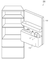
- FIG. 1 is a diagram showing the inside of the refrigerator 100 according to the embodiment.
- the refrigerator 100 includes a pocket 110 capable of accommodating a plurality of liquid containers 2.
- the pocket 110 is provided, for example, inside the door 102.
- the pocket 110 is composed of two rows, but may be one row.
- the refrigerator 100 can detect the remaining amount of the liquid container 2 housed in the pocket 110.
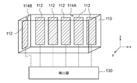
- FIG. 2 is a diagram illustrating the structure of the pocket 110.
- the pocket 110 has a first sensor electrode 112.
- the first sensor electrode 112 is provided on the inner wall 114 of the pocket 110 in contact with the side surface of the liquid container 2.
- the first sensor electrode 112 may be exposed or may be embedded in the inner wall 114.
- the position of the first sensor electrode 112 is not limited, and it may be arranged at a position where it comes into contact with the liquid container 2 whose remaining amount is to be detected.
- the number of first sensor electrodes 112 is not particularly limited.
- the plurality of first sensor electrodes 112 are connected to the detector 130.
- the detector 130 detects the capacitance Cs formed between the plurality of first sensor electrodes 112 and the liquid container 2 to be detected. Then, the remaining amount of the liquid container 2 is acquired based on the capacitance Cs of each first sensor electrode 112.
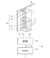
- FIG. 3 is a diagram for explaining the principle of remaining amount detection.
- the first sensor electrode 112 includes a plurality of sub-electrodes Es1 to Esn adjacent to each other in the depth direction of the liquid container 2.
- the detector 130 includes a capacitance detection circuit 132 and an arithmetic processing unit 134.
- the arithmetic processing unit 134 receives detection data indicating the capacitances Cs1 to Csn of the plurality of sub electrodes Es1 to Esn, and acquires the liquid level 6 based on the detection data.
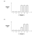
- FIG. 4 (a) and 4 (b) are diagrams showing an example of the capacitance of the plurality of sub electrodes Es1 to Es6.
- the capacitances Cs1 to Cs3 of the sub-electrodes Es1 to Es3 are relatively small, and the capacitances Cs4 to Cs6 of the sub-electrodes Es4 to Es6 are relatively large. Therefore, as shown in FIG. 3, the arithmetic processing unit 134 can determine that the liquid level 6 is between the third and fourth.
- the capacitances Cs1 to Es3 of the sub-electrodes Es1 to Cs3 are relatively small, and the capacitances Cs5 to Cs6 of the sub-electrodes Es5 to Es6 are relatively large, and the fourth sub-electrode.
- the capacitance Cs4 of Es4 shows an intermediate value.
- the arithmetic processing unit 134 may determine that the liquid level 6 is in the range of the fourth sub-electrode Es4.
- the arithmetic processing unit 134 may estimate at which position in the range of the fourth sub-electrode Es4 the liquid level 6 exists based on the value of the capacitance Cs4.
- the first sensor electrode 112 is provided on the inner wall 114 of the pocket 110 in contact with the liquid container 2, and the capacitance formed by the first sensor electrode 112 with the liquid container 2 is measured. , The remaining amount can be detected.
- the liquid level 6 that is, the remaining amount is detected based on the relative relationship between the capacitances Cs1 to Csn of the plurality of sub electrodes Es1 to Esn. Therefore, the remaining amount can be accurately detected without being affected by the material and contents of the liquid container 2.
- the method for detecting the liquid level and the shape and arrangement of the electrodes are not limited to this, and various known methods can be used.
- Example 1 5 (a) to 5 (c) are views showing the pocket 110A according to the first embodiment.
- the pocket 110A includes a plurality of cartridges 120 and holders 122.
- the cartridge 120 can accommodate one liquid container 2.
- the cartridge 120 is removable and movable from the holder 122.
- the cartridge 120 may have a shape suitable for the liquid container 2.
- the liquid container 2 is a milk carton
- its cross-sectional shape is substantially standardized, and 70 mm square is the mainstream, and some 57 mm square are also in circulation.
- some may be designed exclusively for milk cartons.
- the diameter or the length of one side of a PET bottle that stores water and soft drinks is also approximately determined. Therefore, some of the cartridges 120 may be designed exclusively for PET bottles.
- a first sensor electrode 112 composed of a plurality of sub electrodes Es is provided on the surface S1 of the cartridge 120 facing the liquid container 2.
- the detector 130 is provided outside the holder 122 or the holder 122 instead of the cartridge 120 side.
- the cartridge 120 is provided with an interface 124 for connecting the first sensor electrode 112 and the detector 130. As shown in FIG. 5C, the interface 124 may be provided on the surface S2 opposite to the first sensor electrode 112 of the cartridge 120.
- the holder 122 has a plurality of interfaces 126_1 to 126_3 in contact with the interfaces 124_1 to 124_3 on the side of the plurality of cartridges 120.
- the cartridges 120_1 to 120_3 have interfaces 124_1 to 124_3 formed at different heights. Further, as shown in FIG. 5A, the interfaces 126_1 to 126_3 are provided at different heights so as to be in contact with the corresponding interface 124.
- the interfaces 126_1 to 126_3 are formed in a rail shape extending in the first direction.
- the interface 124 may be provided on the bottom surface of the cartridge 120. In this case, the position of the interface 126 on the holder 122 side may also be changed.
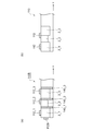
- FIG. 6A is a plan view of the pocket 110B according to the second embodiment as viewed from above.
- the pocket 110B in FIG. 6A is a direct type pocket that directly houses the liquid container 2 without using a cartridge.
- a plurality of liquid containers 2 can be accommodated in the pocket 110B side by side in the first direction (x direction in the drawing).
- the plurality of first sensor electrodes 112 are provided apart from each other in the first direction.
- the pocket 110B further comprises an insulator partition plate 140 located between adjacent liquid containers 2. The partition plate 140 can be moved in the first direction according to the size and position of the liquid container 2.
- FIG. 6B is a diagram showing a pocket 110 having no partition plate 140. If the partition plate 140 is not present, the plurality of liquid containers 2_2 and 2_3 will come into contact with one first sensor electrode 112_2 at the same time. In this case, the remaining amount detection based on the output of the first sensor electrode 112_2 is uncertain. Further, when the pocket 110 is provided inside the door as shown in FIG. 1, the position of the liquid container 2 may move due to the opening and closing of the door.
- the partition plate 140 by providing the partition plate 140, it is possible to avoid a state in which a plurality of liquid containers 2 are in contact with one first sensor electrode 112. Further, it is possible to prevent the liquid container 2 from moving by opening and closing the door.
- the pocket 110B may include a first sensor electrode 112B provided on a surface perpendicular to the x direction.
- the liquid container 2_1 and the first sensor electrode 112B can be brought into close contact with each other without a gap. As a result, the remaining amount of the liquid container 2_1 can be accurately measured.
- the first sensor electrode 112B When the first sensor electrode 112B is provided, the first sensor electrode 112_1 may be omitted.
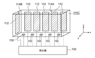
- FIG. 7 is a diagram showing the pocket 110C according to the third embodiment.
- the pocket 110C in FIG. 7 is also a direct system that does not use a cartridge.
- the pocket 110C has a plurality of second sensor electrodes 150 provided on the surface S3 in contact with the bottom surface of the liquid container 2. The position of the second sensor electrode 150 in the x direction may be aligned with the position of the first sensor electrode 112.
- the detector 130 detects the capacitance formed between the plurality of first sensor electrodes 112 and the plurality of second sensor electrodes 150 with a liquid container (not shown).
- a liquid container not shown.
- the second sensor electrode 150 may be provided on the bottom surface of the cartridge described in the first embodiment, and the presence or absence of a liquid container may be determined for each cartridge.
- FIG. 8 is a diagram showing the pocket 110D according to the fourth embodiment.
- the pocket 110D in FIG. 8 is also a direct system that does not use a cartridge.
- the configuration of the pocket 110D for detecting the cross-sectional shape of the liquid container 2 will be described.
- the detector 130 can detect the capacitance (Ce1 to Cem in FIG. 9) formed by the plurality of third electrodes 160_1 to 160_m.
- FIG. 9 (a) and 9 (b) are plan views illustrating the function of the pocket 110D of FIG.
- FIG. 9A shows how the liquid container 2 having a quadrangular cross section is housed in the pocket 110D
- FIG. 9B shows the liquid container 2 having a circular cross section being housed in the pocket 110D. The state is shown.
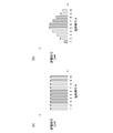
- FIGS. 9 (a) and 10 (b) are diagrams showing the capacitances Ce1 to Ce10 of the plurality of third electrodes 160 measured in the states of FIGS. 9 (a) and 9 (b).
- the cross section of the liquid container 2 is rectangular, the capacitances Ce1 to Ce10 are flat as shown in FIG. 10A.
- the cross section of the liquid container 2 is circular, the capacitances Ce1 to Ce10 have a peak at a certain electrode position and become smaller as the distance from the electrode position increases, as shown in FIG. 10 (b).
- the cross-sectional shape of the liquid container 2 can be measured.
- a plurality of third sensor electrodes 160 may be provided on the side surface of the cartridge described in the first embodiment, and the shape of the liquid container may be measured for each cartridge.
- FIG. 11 is a diagram showing the pocket 110E according to the fifth embodiment.
- the pocket 110E in FIG. 11 is also a direct system that does not use a cartridge.
- the pocket 110E has a plurality of sensor electrodes 170 provided in a matrix on an inner wall 114 in contact with the side surfaces of the plurality of liquid containers 2.
- the sensor electrode 170 also serves as a first sensor electrode 112 for detecting the remaining amount and a third electrode 160 for measuring the cross-sectional shape.
- the detector 130 detects the capacitance formed between the plurality of sensor electrodes 170 and the liquid container 2.
- the detector 130 can detect the remaining amount and the shape of the plurality of liquid containers 2 based on the states of the plurality of sensor electrodes 170.
- a plurality of sensor electrodes 170 may be provided for each cartridge described in the first embodiment, and the remaining amount and shape of the liquid container may be measured for each cartridge.
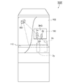
- FIG. 12 is a diagram showing a refrigerator 100F according to a modified example.
- the refrigerator 100F includes a camera 180 that photographs a pocket 110 inside the refrigerator 100F.
- the display 190 is provided on the front side of the door 102 of the refrigerator 100F, and displays an image IMG taken by the camera 180.
- the display 190 displays information indicating the remaining amount for each of the liquid containers 2x and 2y contained in the image IMG.
- the method of displaying the remaining amount is not particularly limited, but for example, as shown in FIG. 12, the remaining amount may be graphically indicated by using an indicator 192 as shown by hatching.
- the user can intuitively and visually know which liquid container has how much remaining amount without opening the refrigerator 100F.
- the present invention relates to a technique for detecting the remaining amount of liquid in a refrigerator.
- Liquid container 4 Liquid 6 Liquid level 100 Refrigerator 102 Door 110 Pocket 112 1st sensor electrode Es Sub electrode 114 Inner wall 120 Cartridge 122 Holder 124, 126 Interface 130 Detector 132 Capacitance detection circuit 134 Calculation processing unit 140 Partition plate 150 No. 2 Sensor electrode 160 3rd electrode 170 Sensor electrode 180 Camera 190 Display
Landscapes
- Engineering & Computer Science (AREA)
- Physics & Mathematics (AREA)
- Thermal Sciences (AREA)
- Power Engineering (AREA)
- General Engineering & Computer Science (AREA)
- Mechanical Engineering (AREA)
- Chemical & Material Sciences (AREA)
- Combustion & Propulsion (AREA)
- Electromagnetism (AREA)
- Fluid Mechanics (AREA)
- General Physics & Mathematics (AREA)
- Cold Air Circulating Systems And Constructional Details In Refrigerators (AREA)
- Measurement Of Levels Of Liquids Or Fluent Solid Materials (AREA)
- Devices That Are Associated With Refrigeration Equipment (AREA)
- Ink Jet (AREA)
Abstract
冷蔵庫は、複数の液体容器を格納可能なポケット110を有する。ポケット110は、複数の液体容器の側面と接触する内壁114Aに設けられた第1センサ電極112を有する。検出器130は、第1センサ電極112の状態にもとづいて、第1センサ電極112と接触する液体容器2の残量を検出する。
Description
本発明は、冷蔵庫内の液体残量の検出技術に関する。
容器やタンク内の液体の量、すなわち液位を検出するセンサとして、フロート(浮き)式のものや、光学式のものが知られている。
近年、家電製品のIoT(Internet Of Things)化が進められており、冷蔵庫などの貯蔵庫も例外ではない。冷蔵庫には、水、牛乳やジュースなどの液体が、それぞれに固有の容器に収容された状態で保存される。
容器には不透明のものがあるため、光学式のセンサを用いることができない。また容器の重量はさまざまであるから、重量にもとづいて残量を推定することも難しい。
本発明は係る状況においてなされたものであり、そのある態様の例示的な目的のひとつは、液体容器内の残量を検出可能な冷蔵庫の提供にある。
本開示のいくつかの例示的な実施形態の概要を説明する。この概要は、後述する詳細な説明の前置きとして、実施形態の基本的な理解を目的として、1つまたは複数の実施形態のいくつかの概念を簡略化して説明するものであり、発明あるいは開示の広さを限定するものではない。またこの概要は、考えられるすべての実施形態の包括的な概要ではなく、実施形態の欠くべからざる構成要素を限定するものではない。便宜上、「一実施形態」は、本明細書に開示するひとつ実施形態または複数の実施形態を指すものとして用いる場合がある。
一実施の形態に係る冷蔵庫は、複数の液体容器を格納可能であり、複数の液体容器の側面と接触する内壁に設けられた第1センサ電極を有するポケットと、第1センサ電極の状態にもとづいて、当該第1センサ電極と接触する液体容器の残量を検出する検出器と、を備える。
第1センサ電極が液体容器との間に形成する静電容量を測定することにより、残量を検出することができる。
一実施形態において、ポケットは、それぞれが1本の液体容器を収容可能な複数のカートリッジと、複数のカートリッジが着脱可能なホルダーと、を備えてもよい。ポケットにはカートリッジごとに、第1センサ電極が設けられてもよい。これにより、液体容器と第1センサ電極の位置ズレを防止できるため、残量を正確に検出できる。
一実施形態において、液体容器は規格化されたサイズを有してもよい。この場合、規格で定められたサイズの容器に適合するように、ポケットを設計することにより、位置ズレなどを防止できるため、残量検出の精度を高めることができる。液体容器の内容物は牛乳であってもよい。
一実施形態において、ポケットは、複数の液体容器を第1方向に並べて収容可能であり、第1センサ電極が複数個、第1方向に離間して設けられてもよい。
一実施形態において、ポケットは、隣接する液体容器の間に位置する絶縁体の仕切り板をさらに備えてもよい。仕切り板によって、各液体容器を、対応する第1センサ電極と対向する位置に固定することができ、また、ひとつの第1センサ電極に、複数の液体容器が接触するのを防止できる。
一実施形態において、仕切り板は、第1方向に移動可能であってもよい。これにより様々な大きさの液体容器に対応できる。
一実施形態において、ポケットは、液体容器の底面と接触する面に設けられた複数の第2センサ電極をさらに備えてもよい。これにより、液体容器の有無を判定できる。
一実施形態において、ポケットは、内壁の同じ高さに第1方向に密に並べられた複数の第3センサ電極をさらに備えてもよい。これにより、液体容器の断面形状を判定できる。
一実施の形態に係る冷蔵庫は、複数の液体容器を格納可能であり、複数の液体容器の側面と接触する内壁にマトリクス状に設けられた複数のセンサ電極を有するポケットと、複数のセンサ電極の状態にもとづいて、複数の液体容器の残量および形状を検出する検出器と、を備える。
一実施の形態において、冷蔵庫は、冷蔵庫の内部に設けられ、ポケットを撮影するカメラと、冷蔵庫のドアに設けられ、カメラが撮影した画像を表示するディスプレイと、をさらに備えてもよい。
一実施の形態において、ディスプレイは、画像に含まれる液体容器それぞれについて、残量を示す情報を表示してもよい。これによりユーザは、冷蔵庫を開けなくても、直感的かつ視覚的に、どの液体容器にどの程度の残量があるのかを知ることができる。
なお、以上の構成要素を任意に組み合わせたもの、あるいは本発明の表現を、方法、装置などの間で変換したものもまた、本発明の態様として有効である。
本発明のある態様によれば、さまざまな容器に収容される液体の残量を検出できる。
以下、本発明を好適な実施の形態をもとに図面を参照しながら説明する。各図面に示される同一または同等の構成要素、部材、処理には、同一の符号を付するものとし、適宜重複した説明は省略する。また、実施の形態は、発明を限定するものではなく例示であって、実施の形態に記述されるすべての特徴やその組み合わせは、必ずしも発明の本質的なものであるとは限らない。
図1は、実施の形態に係る冷蔵庫100の内部を示す図である。冷蔵庫100は、複数の液体容器2を収容可能なポケット110を備える。その限りでないが、ポケット110はたとえばドア102の内側に設けられている。図1では、ポケット110は二列で構成されるが、一列であってもよい。冷蔵庫100は、ポケット110に収容される液体容器2の残量を検出可能である。
図2は、ポケット110の構造を説明する図である。ポケット110は、第1センサ電極112を有する。第1センサ電極112は、液体容器2の側面と接触するポケット110の内壁114に設けられる。第1センサ電極112は露出していてもよいし、内壁114に埋め込まれていてもよい。第1センサ電極112の位置は限定されず、残量を検出したい液体容器2と接触する位置に配置すればよい。また第1センサ電極112の個数は特に限定されない。複数の第1センサ電極112は、検出器130と接続される。検出器130は、複数の第1センサ電極112が、検出対象の液体容器2との間に形成する静電容量Csを検出する。そして各第1センサ電極112の静電容量Csにもとづいて、液体容器2の残量を取得する。
図3は、残量検出の原理を説明する図である。たとえば第1センサ電極112は、液体容器2の深さ方向に隣接する複数のサブ電極Es1~Esnを含む。検出器130は、静電容量検出回路132および演算処理部134を備える。静電容量検出回路132は、複数のサブ電極Es1~Esnと接続され、各サブ電極Esの静電容量を検出可能に構成される。この例ではn=6である。複数のサブ電極Es1~Esnのうち、液体4の液位6よりも上側のサブ電極Esi(i=1,2,3)については、静電容量Csiが相対的に小さくなり、液位6よりも下側のサブ電極Esj(j=4~6)については、静電容量Csjが相対的に大きくなる。演算処理部134は、複数のサブ電極Es1~Esnの静電容量Cs1~Csnを示す検出データを受け、この検出データにもとづいて、液位6を取得する。
図4(a)、(b)は、複数のサブ電極Es1~Es6の静電容量の例を示す図である。図4(a)の例では、サブ電極Es1~Es3の静電容量Cs1~Cs3が相対的に小さく、サブ電極Es4~Es6の静電容量Cs4~Cs6が相対的に大きくなっている。したがって、演算処理部134は、図3に示すように、3番目と4番目の間に、液位6があることと判定できる。
図4(b)の例では、サブ電極Es1~Cs3の静電容量Cs1~Es3が相対的に小さく、サブ電極Es5~Es6の静電容量Cs5~Cs6が相対的に大きく、4番目のサブ電極Es4の静電容量Cs4が、中間的な値を示している。この場合、演算処理部134は、4番目のサブ電極Es4の範囲に液位6があると判定してもよい。演算処理部134は、静電容量Cs4の値にもとづいて、4番目のサブ電極Es4の範囲のどの位置に、液位6が存在するのかを推定してもよい。
以上が冷蔵庫100の構成である。この冷蔵庫100によれば、液体容器2と接触するポケット110の内壁114に第1センサ電極112を設け、第1センサ電極112が液体容器2との間に形成する静電容量を測定することにより、残量を検出することができる。
また図3のポケット110による液位の検出手法によれば、複数のサブ電極Es1~Esnの静電容量Cs1~Csnの相対的な関係にもとづいて、液位6すなわち残量を検出する。したがって、液体容器2の材質や、内容物の影響を受けずに、残量を正確に検出することができる。
なお、液位の検出方法や電極の形状、配置はこれに限定されず、公知のさまざま手法を用いることができる。
(実施例1)
図5(a)~(c)は、実施例1に係るポケット110Aを示す図である。図5(a)に示すように、ポケット110Aは、複数のカートリッジ120とホルダー122を備える。カートリッジ120は、1本の液体容器2を収容可能である。ホルダー122には、カートリッジ120が着脱および移動可能となっている。
図5(a)~(c)は、実施例1に係るポケット110Aを示す図である。図5(a)に示すように、ポケット110Aは、複数のカートリッジ120とホルダー122を備える。カートリッジ120は、1本の液体容器2を収容可能である。ホルダー122には、カートリッジ120が着脱および移動可能となっている。
カートリッジ120は、液体容器2に適合する形状を有するとよい。たとえば液体容器2が牛乳パックである場合、その断面形状は実質的に規格化されており、70mm角が主流となっており、一部、57mm角のものも流通している。複数のカートリッジ120のうち、いくつかは牛乳パック専用に設計してもよい。また、水や清涼飲料水を収容するペットボトルの直径あるいは1辺の長さもおおよそ決まっている。したがって、カートリッジ120のうちいくつかは、ペットボトル専用に設計してもよい。
図5(b)に示すように、カートリッジ120の液体容器2と対向する面S1には、複数のサブ電極Esからなる第1センサ電極112が設けられる。
検出器130の動作には電源が必要であるため、検出器130は、カートリッジ120側でなく、ホルダー122あるいはホルダー122の外部に設けることが好ましい。この場合、カートリッジ120には、第1センサ電極112と、検出器130を接続するためのインタフェース124が設けられる。図5(c)に示すように、インタフェース124は、カートリッジ120の第1センサ電極112と反対の面S2に設けてもよい。
図5(a)に示すように、ホルダー122は、複数のカートリッジ120側のインタフェース124_1~124_3と接触する複数のインタフェース126_1~126_3を有する。
図5(c)に示すように、カートリッジ120_1~120_3は、それぞれ異なる高さにインタフェース124_1~124_3が形成される。また図5(a)に示すように、インタフェース126_1~126_3は、それぞれが対応するインタフェース124と接触するように、異なる高さに設けられる。複数のカートリッジ120_1~120_3が、第1方向(x方向)に配置されるとき、インタフェース126_1~126_3は、第1方向に伸びるレール状に形成される。そして、カートリッジ120_i(i=1,2,3)は、第1方向のいずれの箇所に置いたとしても、インタフェース124_iとインタフェース126_i同士が接触することが可能となっている。
これにより、カートリッジ120_1~120_3の位置を入れ替えたりすることが可能となる。なお、インタフェース124を、カートリッジ120の底面に設けてもよい。この場合、ホルダー122側のインタフェース126の位置も変更すればよい。
(実施例2)
図6(a)は、実施例2に係るポケット110Bを上から見た平面図である。実施例1では、カートリッジ形式のポケットを説明したが、図6(a)のポケット110Bは、カートリッジを用いず、直接、液体容器2を収容するダイレクト形式のポケットである。ポケット110Bには、複数の液体容器2が第1方向(図中、x方向)に並べて収容可能である。複数の第1センサ電極112は、第1方向に離間して設けられる。ポケット110Bは、隣接する液体容器2の間に位置する絶縁体の仕切り板140をさらに備える。この仕切り板140は、液体容器2の大きさや位置に応じて、第1方向に移動可能である。
図6(a)は、実施例2に係るポケット110Bを上から見た平面図である。実施例1では、カートリッジ形式のポケットを説明したが、図6(a)のポケット110Bは、カートリッジを用いず、直接、液体容器2を収容するダイレクト形式のポケットである。ポケット110Bには、複数の液体容器2が第1方向(図中、x方向)に並べて収容可能である。複数の第1センサ電極112は、第1方向に離間して設けられる。ポケット110Bは、隣接する液体容器2の間に位置する絶縁体の仕切り板140をさらに備える。この仕切り板140は、液体容器2の大きさや位置に応じて、第1方向に移動可能である。
図6(b)は仕切り板140を有しないポケット110を示す図である。仕切り板140が存在しないと、ひとつの第1センサ電極112_2に、複数の液体容器2_2,2_3が同時に接触することとなる。この場合、第1センサ電極112_2の出力にもとづく残量検出は不確かなものとなる。また、図1に示すようにポケット110をドアの内側に設ける場合、ドアの開閉によって、液体容器2の位置が移動するおそれがある。
図6(a)に示すように、仕切り板140を設けることにより、1個の第1センサ電極112に、複数の液体容器2が接触する状態を回避することができる。またドアの開閉によって液体容器2が移動することを防止できる。
図6(a)に示すように、ポケット110Bは、x方向と垂直な面に設けられた第1センサ電極112Bを備えてもよい。仕切り板140_1を左側に寄せることにより、液体容器2_1と第1センサ電極112Bを隙間なく密着させることができる。これにより、液体容器2_1の残量を正確に測定できる。第1センサ電極112Bを設ける場合、第1センサ電極112_1は省略してもよい。
(実施例3)
図7は、実施例3に係るポケット110Cを示す図である。図7のポケット110Cも、カートリッジを用いないダイレクト方式である。ポケット110Cは、液体容器2の底面と接触する面S3に設けられた複数の第2センサ電極150を有する。第2センサ電極150のx方向の位置は、第1センサ電極112の位置と揃えてもよい。
図7は、実施例3に係るポケット110Cを示す図である。図7のポケット110Cも、カートリッジを用いないダイレクト方式である。ポケット110Cは、液体容器2の底面と接触する面S3に設けられた複数の第2センサ電極150を有する。第2センサ電極150のx方向の位置は、第1センサ電極112の位置と揃えてもよい。
検出器130は、複数の第1センサ電極112に加えて、複数の第2センサ電極150が図示しない液体容器との間に形成する静電容量を検出する。第2センサ電極150の静電容量が大きい場合、その上に液体容器2が存在することが推定され、静電容量が小さい場合、液体容器2は存在しないと推定することができる。
なお、第2センサ電極150を、実施例1で説明したカートリッジの底面に設け、カートリッジ毎に液体容器の有無を判定してもよい。
(実施例4)
図8は、実施例4に係るポケット110Dを示す図である。図8のポケット110Dも、カートリッジを用いないダイレクト方式である。このポケット110Dは、液体容器2の断面形状を検出する構成を説明する。ポケット110Dは、第1センサ電極112に加えて、内壁114の同じ高さに第1方向(x方向)に密に並べられた複数の第3電極160_1~160_m(図8ではm=10)を有する。検出器130は、複数の第3電極160_1~160_mが形成する静電容量(図9のCe1~Cem)を検出可能である。
図8は、実施例4に係るポケット110Dを示す図である。図8のポケット110Dも、カートリッジを用いないダイレクト方式である。このポケット110Dは、液体容器2の断面形状を検出する構成を説明する。ポケット110Dは、第1センサ電極112に加えて、内壁114の同じ高さに第1方向(x方向)に密に並べられた複数の第3電極160_1~160_m(図8ではm=10)を有する。検出器130は、複数の第3電極160_1~160_mが形成する静電容量(図9のCe1~Cem)を検出可能である。
図9(a)、(b)は、図8のポケット110Dの機能を説明する平面図である。図9(a)には、ポケット110Dに、断面が四角形の液体容器2が収容される様子が示され、図9(b)には、ポケット110Dに、断面が円形の液体容器2が収容される様子が示される。
図10(a)、(b)は、図9(a)、図9(b)の状態において測定される複数の第3電極160の静電容量Ce1~Ce10を示す図である。液体容器2の断面が矩形の場合、図10(a)に示すように静電容量Ce1~Ce10はフラットになる。液体容器2の断面が円形の場合、静電容量Ce1~Ce10は図10(b)に示すように、ある電極位置でピークを有し、そこから離れるに従って小さくなる。
このようにポケット110Dによれば、液体容器2の断面形状を測定できる。
なお、複数の第3センサ電極160を、実施例1で説明したカートリッジの側面に設け、カートリッジ毎に液体容器の形状を測定してもよい。
(実施例5)
図11は、実施例5に係るポケット110Eを示す図である。図11のポケット110Eも、カートリッジを用いないダイレクト方式である。ポケット110Eは、複数の液体容器2の側面と接触する内壁114にマトリクス状に設けられた複数のセンサ電極170を有する。このセンサ電極170は、残量を検出するための第1センサ電極112と、断面形状を測定するための第3電極160を兼ねている。検出器130は、複数のセンサ電極170それぞれが液体容器2との間に形成する静電容量を検出する。
図11は、実施例5に係るポケット110Eを示す図である。図11のポケット110Eも、カートリッジを用いないダイレクト方式である。ポケット110Eは、複数の液体容器2の側面と接触する内壁114にマトリクス状に設けられた複数のセンサ電極170を有する。このセンサ電極170は、残量を検出するための第1センサ電極112と、断面形状を測定するための第3電極160を兼ねている。検出器130は、複数のセンサ電極170それぞれが液体容器2との間に形成する静電容量を検出する。
検出器130は、複数のセンサ電極170の状態にもとづいて、複数の液体容器2の残量および形状を検出することができる。
なお、複数のセンサ電極170を、実施例1で説明したカートリッジごとに設け、カートリッジ毎に液体容器の残量と形状とを測定してもよい。
図12は、変形例に係る冷蔵庫100Fを示す図である。冷蔵庫100Fは、冷蔵庫100Fの内部のポケット110を撮影するカメラ180を備える。ディスプレイ190は、冷蔵庫100Fのドア102の表側に設けられ、カメラ180が撮影した画像IMGを表示する。
ディスプレイ190は、画像IMGに含まれる液体容器2x,2yそれぞれについて、残量を示す情報を表示する。残量の表示方法は特に限定されないが、たとえば図12に示すように残量を、ハッチングで示すようなインジケータ192を用いてグラフィカルに示してもよい。
ユーザは、冷蔵庫100Fを開けなくても、直感的かつ視覚的に、どの液体容器にどの程度の残量があるのかを知ることができる。
実施の形態にもとづき、具体的な用語を用いて本発明を説明したが、実施の形態は、本発明の原理、応用を示しているにすぎず、実施の形態には、請求の範囲に規定された本発明の思想を逸脱しない範囲において、多くの変形例や配置の変更が認められる。
本発明は、冷蔵庫内の液体残量の検出技術に関する。
2 液体容器
4 液体
6 液位
100 冷蔵庫
102 ドア
110 ポケット
112 第1センサ電極
Es サブ電極
114 内壁
120 カートリッジ
122 ホルダー
124,126 インタフェース
130 検出器
132 静電容量検出回路
134 演算処理部
140 仕切り板
150 第2センサ電極
160 第3電極
170 センサ電極
180 カメラ
190 ディスプレイ
4 液体
6 液位
100 冷蔵庫
102 ドア
110 ポケット
112 第1センサ電極
Es サブ電極
114 内壁
120 カートリッジ
122 ホルダー
124,126 インタフェース
130 検出器
132 静電容量検出回路
134 演算処理部
140 仕切り板
150 第2センサ電極
160 第3電極
170 センサ電極
180 カメラ
190 ディスプレイ
Claims (13)
- 複数の液体容器を格納可能であり、前記複数の液体容器の側面と接触する内壁に設けられた第1センサ電極を有するポケットと、
前記第1センサ電極の状態にもとづいて、前記第1センサ電極と接触する前記液体容器の残量を検出する検出器と、
を備えることを特徴とする冷蔵庫。 - 前記第1センサ電極は、前記液体容器の深さ方向に隣接する複数のサブ電極を含むことを特徴とする請求項1に記載の冷蔵庫。
- 前記ポケットは、
それぞれが1本の前記液体容器を収容可能な複数のカートリッジと、
前記複数のカートリッジが着脱可能なホルダーと、
を備え、
前記カートリッジごとに、前記第1センサ電極が設けられることを特徴とする請求項1または2に記載の冷蔵庫。 - 前記液体容器は規格化されたサイズを有することを特徴とする請求項1から3のいずれかに記載の冷蔵庫。
- 前記液体容器の内容物は牛乳であることを特徴とする請求項4に記載の冷蔵庫。
- 前記ポケットは、前記複数の液体容器を第1方向に並べて収容可能であり、
前記第1センサ電極が複数個、前記第1方向に離間して設けられることを特徴とする請求項1または2に記載の冷蔵庫。 - 前記ポケットは、隣接する前記液体容器の間に位置する絶縁体の仕切り板をさらに備えることを特徴とする請求項6に記載の冷蔵庫。
- 前記仕切り板は、前記第1方向に移動可能であることを特徴とする請求項7に記載の冷蔵庫。
- 前記ポケットは、前記液体容器の底面と接触する面に設けられた複数の第2センサ電極をさらに備えることを特徴とする請求項1から8のいずれかに記載の冷蔵庫。
- 前記ポケットは、前記内壁の同じ高さに前記第1方向に密に並べられた複数の第3センサ電極をさらに備えることを特徴とする請求項6から8のいずれかに記載の冷蔵庫。
- 複数の液体容器を格納可能であり、前記複数の液体容器の側面と接触する内壁にマトリクス状に設けられた複数のセンサ電極を有するポケットと、
前記複数のセンサ電極の状態にもとづいて、前記複数の液体容器の残量および形状を検出する検出器と、
を備えることを特徴とする冷蔵庫。 - 前記冷蔵庫の内部に設けられ、前記ポケットを撮影するカメラと、
前記冷蔵庫のドアに設けられ、前記カメラが撮影した画像を表示するディスプレイと、
をさらに備えることを特徴とする請求項1から11のいずれかに記載の冷蔵庫。 - 前記ディスプレイは、前記画像に含まれる前記液体容器それぞれについて、残量を示す情報を表示することを特徴とする請求項12に記載の冷蔵庫。
Priority Applications (5)
| Application Number | Priority Date | Filing Date | Title |
|---|---|---|---|
| JP2021518345A JP7365407B2 (ja) | 2019-05-09 | 2020-04-23 | 冷蔵庫 |
| DE112020002300.1T DE112020002300T5 (de) | 2019-05-09 | 2020-04-23 | Kühlschrank |
| KR1020217035989A KR20220007049A (ko) | 2019-05-09 | 2020-04-23 | 냉장고 |
| CN202080033051.8A CN113795719A (zh) | 2019-05-09 | 2020-04-23 | 冰箱 |
| US17/520,928 US20220057248A1 (en) | 2019-05-09 | 2021-11-08 | Refrigerator |
Applications Claiming Priority (2)
| Application Number | Priority Date | Filing Date | Title |
|---|---|---|---|
| JP2019-089180 | 2019-05-09 | ||
| JP2019089180 | 2019-05-09 |
Related Child Applications (1)
| Application Number | Title | Priority Date | Filing Date |
|---|---|---|---|
| US17/520,928 Continuation US20220057248A1 (en) | 2019-05-09 | 2021-11-08 | Refrigerator |
Publications (1)
| Publication Number | Publication Date |
|---|---|
| WO2020226068A1 true WO2020226068A1 (ja) | 2020-11-12 |
Family
ID=73051057
Family Applications (1)
| Application Number | Title | Priority Date | Filing Date |
|---|---|---|---|
| PCT/JP2020/017545 Ceased WO2020226068A1 (ja) | 2019-05-09 | 2020-04-23 | 冷蔵庫 |
Country Status (6)
| Country | Link |
|---|---|
| US (1) | US20220057248A1 (ja) |
| JP (1) | JP7365407B2 (ja) |
| KR (1) | KR20220007049A (ja) |
| CN (1) | CN113795719A (ja) |
| DE (1) | DE112020002300T5 (ja) |
| WO (1) | WO2020226068A1 (ja) |
Cited By (1)
| Publication number | Priority date | Publication date | Assignee | Title |
|---|---|---|---|---|
| WO2025126268A1 (ja) * | 2023-12-11 | 2025-06-19 | 三菱電機株式会社 | 冷蔵庫及び冷蔵システム |
Citations (7)
| Publication number | Priority date | Publication date | Assignee | Title |
|---|---|---|---|---|
| JP2003090673A (ja) * | 2001-09-17 | 2003-03-28 | Hitachi Electronics Service Co Ltd | 冷蔵庫収納品画像表示システム |
| JP2009525449A (ja) * | 2006-01-31 | 2009-07-09 | エレクトロラックス ホーム プロダクツ コーポレイション ナームロゼ フェンノートシャップ | 飲料用急速冷却装置およびその制御方法 |
| JP2012042173A (ja) * | 2010-08-23 | 2012-03-01 | Mitsubishi Electric Corp | 冷蔵庫および食品管理方法 |
| JP2015152216A (ja) * | 2014-02-13 | 2015-08-24 | 日本写真印刷株式会社 | 製品検出装置 |
| WO2016151814A1 (ja) * | 2015-03-25 | 2016-09-29 | 三菱電機株式会社 | 冷蔵庫 |
| JP2017161143A (ja) * | 2016-03-09 | 2017-09-14 | 東芝ライフスタイル株式会社 | 冷蔵庫 |
| WO2017190946A1 (de) * | 2016-05-02 | 2017-11-09 | BSH Hausgeräte GmbH | Kältegerät, fachboden und verfahren zur überwachung von kühlgut |
Family Cites Families (3)
| Publication number | Priority date | Publication date | Assignee | Title |
|---|---|---|---|---|
| KR20110139844A (ko) * | 2010-06-24 | 2011-12-30 | 삼성전자주식회사 | 센서장치를 갖는 냉장고용 수납용기 및 이를 갖는 냉장고 |
| KR101373088B1 (ko) * | 2011-09-08 | 2014-03-11 | 히타치 어플라이언스 가부시키가이샤 | 냉장고 |
| GB2539099A (en) * | 2015-06-05 | 2016-12-07 | Toshiba Kk | Refrigerator |
-
2020
- 2020-04-23 DE DE112020002300.1T patent/DE112020002300T5/de active Pending
- 2020-04-23 WO PCT/JP2020/017545 patent/WO2020226068A1/ja not_active Ceased
- 2020-04-23 JP JP2021518345A patent/JP7365407B2/ja active Active
- 2020-04-23 CN CN202080033051.8A patent/CN113795719A/zh not_active Withdrawn
- 2020-04-23 KR KR1020217035989A patent/KR20220007049A/ko not_active Withdrawn
-
2021
- 2021-11-08 US US17/520,928 patent/US20220057248A1/en not_active Abandoned
Patent Citations (7)
| Publication number | Priority date | Publication date | Assignee | Title |
|---|---|---|---|---|
| JP2003090673A (ja) * | 2001-09-17 | 2003-03-28 | Hitachi Electronics Service Co Ltd | 冷蔵庫収納品画像表示システム |
| JP2009525449A (ja) * | 2006-01-31 | 2009-07-09 | エレクトロラックス ホーム プロダクツ コーポレイション ナームロゼ フェンノートシャップ | 飲料用急速冷却装置およびその制御方法 |
| JP2012042173A (ja) * | 2010-08-23 | 2012-03-01 | Mitsubishi Electric Corp | 冷蔵庫および食品管理方法 |
| JP2015152216A (ja) * | 2014-02-13 | 2015-08-24 | 日本写真印刷株式会社 | 製品検出装置 |
| WO2016151814A1 (ja) * | 2015-03-25 | 2016-09-29 | 三菱電機株式会社 | 冷蔵庫 |
| JP2017161143A (ja) * | 2016-03-09 | 2017-09-14 | 東芝ライフスタイル株式会社 | 冷蔵庫 |
| WO2017190946A1 (de) * | 2016-05-02 | 2017-11-09 | BSH Hausgeräte GmbH | Kältegerät, fachboden und verfahren zur überwachung von kühlgut |
Cited By (1)
| Publication number | Priority date | Publication date | Assignee | Title |
|---|---|---|---|---|
| WO2025126268A1 (ja) * | 2023-12-11 | 2025-06-19 | 三菱電機株式会社 | 冷蔵庫及び冷蔵システム |
Also Published As
| Publication number | Publication date |
|---|---|
| DE112020002300T5 (de) | 2022-02-17 |
| KR20220007049A (ko) | 2022-01-18 |
| JPWO2020226068A1 (ja) | 2020-11-12 |
| US20220057248A1 (en) | 2022-02-24 |
| CN113795719A (zh) | 2021-12-14 |
| JP7365407B2 (ja) | 2023-10-19 |
Similar Documents
| Publication | Publication Date | Title |
|---|---|---|
| ES2753098T3 (es) | Sistemas y métodos para determinar el contenido, la localización, y el entorno de un recipiente | |
| TWI447358B (zh) | 液體位準感測裝置及方法 | |
| CA2996490C (en) | Container holding member and medical container set | |
| US20100101317A1 (en) | Lid based amount sensor | |
| WO2010036779A1 (en) | Methods and apparatuses for dispensing fluids | |
| JP2012008129A (ja) | 容器内の充填媒質の非侵襲性容量式充填レベル測定装置および方法 | |
| JP7365407B2 (ja) | 冷蔵庫 | |
| US11351087B2 (en) | Apparatus for monitoring the content of a container and method therefor | |
| CN105204476A (zh) | 一种多功能智能药箱 | |
| AU2004258013C1 (en) | Device for judging types of liquid in container and control method therefor | |
| US11624645B2 (en) | Method and refrigerating device for determining an object weight of an object for refrigeration | |
| JP2018536511A (ja) | 通信型薬品パッケージング | |
| US10262295B2 (en) | Wireless remote monitoring of supply bins | |
| JP2006051178A (ja) | 薬剤包装装置 | |
| JP2006158712A (ja) | 心拍計測装置 | |
| US7628117B2 (en) | Over temperature alarm indication apparatus | |
| US20020162235A1 (en) | Tilt sensor or an automatic leveling device | |
| Kreutzer et al. | Capacitive detection of filling levels in a cup | |
| RU2415055C2 (ru) | Системы и способы обнаружения жидкостей | |
| ES2976788T3 (es) | Dispositivo receptáculo y procedimiento de identificación de elementos de trabajo | |
| CN100460869C (zh) | 一种用于判断容器内的液体类型的装置及其控制方法 | |
| Mamishev et al. | Spill-O-Not: A contactless material level indicator for visually impaired users | |
| WO2022232519A1 (en) | Container and automated accessioning and assembly platform | |
| EP3705108A1 (en) | Device for monitoring the medication of a patient | |
| JP4502374B2 (ja) | 薬品収納用カセット及び薬品収納装置 |
Legal Events
| Date | Code | Title | Description |
|---|---|---|---|
| 121 | Ep: the epo has been informed by wipo that ep was designated in this application |
Ref document number: 20802547 Country of ref document: EP Kind code of ref document: A1 |
|
| ENP | Entry into the national phase |
Ref document number: 2021518345 Country of ref document: JP Kind code of ref document: A |
|
| 122 | Ep: pct application non-entry in european phase |
Ref document number: 20802547 Country of ref document: EP Kind code of ref document: A1 |