WO2020217488A1 - Wireless base station - Google Patents
Wireless base station Download PDFInfo
- Publication number
- WO2020217488A1 WO2020217488A1 PCT/JP2019/018056 JP2019018056W WO2020217488A1 WO 2020217488 A1 WO2020217488 A1 WO 2020217488A1 JP 2019018056 W JP2019018056 W JP 2019018056W WO 2020217488 A1 WO2020217488 A1 WO 2020217488A1
- Authority
- WO
- WIPO (PCT)
- Prior art keywords
- gnb
- communication device
- time
- reference time
- information
- Prior art date
Links
Images


Classifications
-
- H—ELECTRICITY
- H04—ELECTRIC COMMUNICATION TECHNIQUE
- H04W—WIRELESS COMMUNICATION NETWORKS
- H04W56/00—Synchronisation arrangements
- H04W56/001—Synchronization between nodes
- H04W56/0015—Synchronization between nodes one node acting as a reference for the others
-
- H—ELECTRICITY
- H04—ELECTRIC COMMUNICATION TECHNIQUE
- H04L—TRANSMISSION OF DIGITAL INFORMATION, e.g. TELEGRAPHIC COMMUNICATION
- H04L1/00—Arrangements for detecting or preventing errors in the information received
- H04L1/12—Arrangements for detecting or preventing errors in the information received by using return channel
- H04L1/16—Arrangements for detecting or preventing errors in the information received by using return channel in which the return channel carries supervisory signals, e.g. repetition request signals
- H04L1/1607—Details of the supervisory signal
- H04L1/1642—Formats specially adapted for sequence numbers
-
- H—ELECTRICITY
- H04—ELECTRIC COMMUNICATION TECHNIQUE
- H04J—MULTIPLEX COMMUNICATION
- H04J3/00—Time-division multiplex systems
- H04J3/02—Details
- H04J3/06—Synchronising arrangements
- H04J3/0635—Clock or time synchronisation in a network
- H04J3/0638—Clock or time synchronisation among nodes; Internode synchronisation
- H04J3/0644—External master-clock
-
- H—ELECTRICITY
- H04—ELECTRIC COMMUNICATION TECHNIQUE
- H04L—TRANSMISSION OF DIGITAL INFORMATION, e.g. TELEGRAPHIC COMMUNICATION
- H04L5/00—Arrangements affording multiple use of the transmission path
- H04L5/003—Arrangements for allocating sub-channels of the transmission path
- H04L5/0053—Allocation of signaling, i.e. of overhead other than pilot signals
-
- H—ELECTRICITY
- H04—ELECTRIC COMMUNICATION TECHNIQUE
- H04W—WIRELESS COMMUNICATION NETWORKS
- H04W56/00—Synchronisation arrangements
- H04W56/001—Synchronization between nodes
-
- H—ELECTRICITY
- H04—ELECTRIC COMMUNICATION TECHNIQUE
- H04W—WIRELESS COMMUNICATION NETWORKS
- H04W88/00—Devices specially adapted for wireless communication networks, e.g. terminals, base stations or access point devices
- H04W88/08—Access point devices
- H04W88/085—Access point devices with remote components
Definitions
- the present invention relates to a radio base station that delivers a reference time.
- LTE Long Term Evolution
- LTE-Advanced LTE-Advanced
- 5G New Radio NR
- a radio base station In the Industrial Internet of Things (IIoT), in order to support Time-Sensitive Networking (TSN), a radio base station (gNB) is applied in at least one of the NR system and TSN in the NR system. It is being considered to deliver the reference time to the user device (UE) (see Non-Patent Document 1). As a result, the UE can perform time synchronization based on the reference time.
- IIoT Time-Sensitive Networking
- Non-Patent Document 1 discusses that gNB uses at least one of broadcast radio resource control (RRC) signaling and unicast RRC signaling to deliver a reference time to the UE.
- RRC radio resource control
- gNB is separated into a Central Unit (gNB-CU) and a Distributed Unit (gNB-DU) that projects from the installation location of the gNB-CU and is located remotely.
- gNB-CU Central Unit
- gNB-DU Distributed Unit
- gNB-DU is provided with a lower layer such as a wireless link control layer (RLC), and gNB-CU is higher than the packet data convergence protocol layer (PDCP).
- RLC wireless link control layer
- PDCP packet data convergence protocol layer
- HLS CU-DU Higher Layer Split
- RRC signaling is transmitted by gNB-CU.
- gNB-CU uses RRC signaling to deliver the reference time to the UE
- gNB-CU and gNB-DU are physically separated from each other, so gNB-CU and gNB- Delivery delays may occur with the DU.
- gNB cannot deliver the exact reference time to the UE.
- an object of the present invention is to provide a wireless base station capable of delivering an accurate reference time to a user device in HLS.
- the radio base station (200) is connected to a first communication device (230) that communicates with a predetermined user device (100) and the first communication device (230), and the first communication device (230) is connected.
- the second communication device (210) includes a second communication device (210) that communicates with the predetermined user device (100) via the communication device (230), and the second communication device (210) sends a request signal to the first communication device (210).
- the first communication device (230) includes a transmitting unit (211) for transmitting to the 230), a receiving unit (233) for receiving the request signal, and a reference system frame number and a reference system frame number based on the received request signal.
- a transmission unit (231) for transmitting a reference time in a predetermined network associated with the reference system frame number to the second communication device (210) is provided, and a transmission unit of the second communication device (210) is provided.
- (211) transmits a radio resource control message including the reference system frame number and the reference time to the predetermined user device (100) via the first communication device (230).
- the radio base station (200) is connected to a first communication device (230) that communicates with a predetermined user device (100) and the first communication device (230), and the first communication device (230) is connected.
- the second communication device (210) includes the second communication device (210) that communicates with the predetermined user device (100) via the communication device (230), and the second communication device (210) is the same as the predetermined user device (100).
- the first communication device (230) includes a transmission unit (211) for transmitting predetermined information for communication to the first communication device (230), and the first communication device (230) has a receiving unit (233) for receiving the predetermined information.
- the radio base station (200) is connected to a first communication device (230) that communicates with a predetermined user device (100) and the first communication device (230), and the first communication device (230) is connected.
- the second communication device (210) includes the second communication device (210) that communicates with the predetermined user device (100) via the communication device (230), and the second communication device (210) is the same as the predetermined user device (100).
- a radio resource control (RRC) message including a predetermined information for communication and a reference system frame number and a reference time in a predetermined network associated with the reference system frame number is sent to the first communication device (230).
- the first communication device (230) includes a transmission unit (211) for transmission, the reception unit (233) for receiving the predetermined information and the RRC message, and the reference system frame number included in the received RRC message. And the control unit (235) that updates the reference time, and the RRC message including the updated reference system frame number and the reference time based on the received predetermined information, the predetermined user apparatus (100). It is provided with a transmission unit (231) for transmitting to.
- FIG. 1 is an overall schematic configuration diagram of the remote control system 10.
- FIG. 2 is an overall schematic configuration diagram of the remote control system 10a.
- FIG. 3 is a diagram showing a protocol stack of gNB200.
- FIG. 4 is a functional block configuration diagram of gNB-CU210.
- FIG. 5 is a functional block configuration diagram of gNB-DU230.
- FIG. 6 is a diagram showing a sequence of distribution processing 1 at a reference time in broadcast RRC signaling.
- FIG. 7 is a diagram showing a sequence of distribution processing 2 at a reference time in broadcast RRC signaling.
- FIG. 8 is a diagram showing a sequence of distribution processing 1 at a reference time in unicast RRC signaling.
- FIG. 9 is a diagram showing a sequence of delivery processing 2 at a reference time in unicast RRC signaling.
- FIG. 10 is a diagram showing a sequence of delivery processing 3 at a reference time in unicast RRC signaling.
- FIG. 11 is a diagram showing an example of the hardware configuration of gNB-CU210 and gNB-DU230.
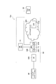
- FIG. 1 is an overall schematic configuration diagram of the remote control system 10 according to the embodiment.
- the remote control system 10 includes a TSN grand master (TSNGM) 20, an NR system 30, and an end station 40.
- TSN control source (not shown) remotely controls the TSN end station 40 in real time via the NR system 30.
- the specific configuration of the remote control system 10 including the number of gNBs and UEs is not limited to the example shown in FIG.
- the TSN GM20 oscillates the clock for generating the TSN time with high accuracy.
- the time generated based on the clock oscillated by the TSN GM20 is referred to as the TSN time.
- the TSN time is the reference time applied within the TSN.
- the NR system 30 includes the NR grandmaster (NR GM) 31, UE100, gNB200, and core network 300.
- the NR GM31 oscillates the clock that is the operation timing of the NR system 30.
- the time generated based on the clock oscillated by the NR GM31 is referred to as the NR time.
- the NR time is the reference time applied within the NR system 30.
- the UE100 executes wireless communication according to NR between UE100 and gNB200 and core network 300.
- the UE100 receives at least one of the broadcast RRC signaling and the unicast RRC signaling including the NR time as the reference time from the gNB200.
- the UE100 synchronizes the time based on the received NR time in order to support TSN.
- the gNB200 executes wireless communication according to NR between the gNB200 and the core network 300.
- the gNB200 is composed of a Central Unit (gNB-CU) 210 and a Distributed Unit (gNB-DU) 230.
- the gNB-CU210 is located on the core network 300 side and controls the gNB-DU230.
- the gNB-CU210 may control a plurality of gNB-DU230s.
- gNB-DU230 is located on the UE100 side.
- the gNB-CU210 is connected to the gNB-DU230 via an F1 interface (for example, an optical fiber).
- the gNB-CU210 communicates with the UE 100 via the gNB-DU230.
- a hub, router, etc. can be installed between the gNB-CU210 and gNB-DU230.
- At least gNB-DU230 performs time synchronization based on the NR time. Note that only gNB-DU230 may perform time synchronization based on the NR time.
- the gNB 200 transmits at least one of the broadcast RRC signaling and the unicast RRC signaling including the NR time as the reference time to the UE 100.
- UE100 and gNB200 include Massive MIMO, which generates a more directional beam by controlling radio signals transmitted from multiple antenna elements, carrier aggregation (CA) using multiple component carriers (CC), and multiple carriers. It is possible to support dual connectivity (DC) in which component carriers are transmitted simultaneously between gNB and UE.
- Massive MIMO which generates a more directional beam by controlling radio signals transmitted from multiple antenna elements, carrier aggregation (CA) using multiple component carriers (CC), and multiple carriers.
- CA carrier aggregation
- CC component carriers
- DC dual connectivity
- the core network 300 communicates with the UE 100 via the gNB 200.
- the core network 300 has a User Plane Function (UPF) 310.
- UPF310 provides functions specialized for U-plane processing.
- the UPF310 is connected to TSN GM20.
- the TSN GM20 may be connected to the gNB 200 instead of the UPF310.
- the gNB 200 can transmit at least one of the broadcast RRC signaling and the unicast RRC signaling including the TSN time as the reference time to the UE 100.
- UE100 performs time synchronization based on the received TSN time in order to support TSN.
- At least gNB-DU230 synchronizes the time based on at least one reference time of NR time and TSN time. Note that only gNB-DU230 may perform time synchronization based on the reference time.
- the gNB 200 may transmit at least one of the broadcast RRC signaling and the unicast RRC signaling including the NR time and the TSN time as the reference time to the UE 100.
- the UE 100 may perform time synchronization based on at least one reference time of the received NR time and TSN time in order to correspond to the TSN.
- the end station 40 is a machine (for example, a robot arm) installed in the production factory.
- the end station 40 receives a command from the TSN control source via the NR system 30.
- the control source of the TSN performs real-time remote control in the remote control system 10 by performing time scheduling for operating the end station 40 based on the TSN time.
- FIG. 3 shows the protocol stack of gNB200.
- gNB200 includes gNB-CU210 and gNB-DU230.
- the gNB-CU210 provides an upper layer, specifically, a packet data convergence protocol layer (PDCP) and a radio resource control layer (RRC).
- PDCP packet data convergence protocol layer
- RRC radio resource control layer
- SDAP service data adaptation protocol layer
- the gNB-CU210 controls the operation of the gNB-DU230.
- the gNB-CU210 terminates the F1 interface with the gNB-DU230.
- the gNB-DU230 provides a lower layer, specifically, a physical layer (L1) and a radio unit (RF), a medium access control layer (MAC), and a radio link control layer (RLC).
- L1 physical layer
- RF radio unit
- MAC medium access control layer
- RLC radio link control layer
- the gNB-DU230 executes communication with the UE100 via the lower layer.
- the gNB-DU 230 constitutes a first communication device that executes wireless communication with the UE 100.
- GNB-DU230 supports one or more cells. One cell is supported by only one gNB-DU.
- the gNB-DU230 terminates the F1 interface with the gNB-CU210.
- gNB-CU210 is connected to gNB-DU230 and communicates with UE100 via RRC, which is higher than lower layers such as RLC.
- the gNB-CU 210 constitutes a second communication device that is connected to the gNB-DU230 and communicates with the UE 100 via the gNB-DU230.
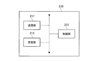
- FIG. 4 is a functional block configuration diagram of gNB-CU210.
- the hardware configuration of gNB-CU210 will be described later.
- the gNB-CU210 includes a transmission unit 211, a reception unit 213, and a control unit 215.
- the transmitter 211 requests the gNB-DU230 to rewrite the coded system information, the coded RRC message, the request signal for requesting the information about the reference time from the gNB-DU230, and the TimeReferenceInforList. It sends a request signal, a message creation instruction to instruct the gNB-DU230 to create an RRC message, and predetermined information for the gNB-DU230 to communicate with the UE100.
- the receiving unit 213 receives the reference SFN, the reference time in the gNB-DU230 associated with the reference SFN, and the like from the gNB-DU230.
- Control unit 215 sets system information, sets RRC messages, encodes system information, encodes RRC messages, and so on.
- FIG. 5 is a functional block configuration diagram of gNB-DU230.
- the hardware configuration of gNB-DU230 will be described later.
- the gNB-DU230 includes a transmission unit 231, a reception unit 233, and a control unit 235.
- the transmission unit 231 transmits the reference SFN, the reference time in the gNB-DU230 associated with the reference SFN, and the like to the gNB-CU210.
- the transmitter 231 transmits the encoded system information, the encoded RRC message, and the like to the UE 100.
- the receiver 233 receives a coded system information, a coded RRC message from the gNB-CU210, a request signal for requesting information about the reference time from the gNB-DU230, and a request message for requesting rewriting of the TimeReferenceInforList. , Receives message creation instructions for instructing gNB-DU230 to create RRC messages, and predetermined information for gNB-DU230 to communicate with UE100.
- Control unit 235 updates (rewrites) system information, sets RRC messages, updates (rewrites) RRC messages, decodes system information, encodes system information, encodes RRC messages, and so on.
- Reference time distribution process 1 In the distribution process 1, the reference time is set for the timeInfoUTC in the system information (for example, System Information Block (SIB) 9) that notifies the time.
- SIB System Information Block
- FIG. 6 is a diagram showing a sequence of distribution processing 1 at a reference time.
- the gNB-CU210 sets the NR time at the timing of delivering the system information to the timeInfoUTC in the system information as the reference time.
- the reference time aaaa is set in the timeInfoUTC in SIB9.
- the gNB-CU210 encodes the system information and transmits it to the gNB-DU230 (S1).
- the gNB-DU230 When the gNB-DU230 receives the system information, it decodes the system information. gNB-DU230 updates the NR time set in timeInfoUTC in the system information to the NR time at the timing of delivering the system information (S2). In this embodiment, the reference time aaaa set in timeInfoUTC in SIB9 is updated to the reference time bbbb.
- the gNB-DU230 encodes the system information and notifies the system information including the updated reference time (S3).
- At least one of the NR time and the TSN time can be set in timeInfoUTC.
- TimeReferenceInfoList is set in the system information for notifying the time (for example, System Information Block (SIB) 9).
- SIB System Information Block
- the system frame number (reference SFN) assigned to the reference wireless frame is set for the referenceSFN in the information element TimeReferenceInfoList. Further, for Time in the information element TimeReferenceInfoList, the NR time in gNB-DU230 associated with the reference SFN set in referenceSFN is set as the reference time.
- the reference time set in Time is, for example, the NR time in the gNB-DU230 at the terminal boundary of the System Information window (SI window), which is the period for transmitting system information, or the SFN boundary immediately after the terminal boundary.
- SI window System Information window
- At least one of the NR time and the TSN time in the gNB-DU230 is set to the Time in the information element TimeReferenceInfoList. be able to.
- FIG. 7 is a diagram showing a sequence of the delivery process 2 at the reference time.
- the gNB-DU230 transmits the reference SFN and the reference time in the gNB-DU230 associated with the reference SFN to the gNB-CU210 based on the request from the gNB-CU210, the predetermined timing, etc. (S11).
- the reference SFN XXX is transmitted as the reference SFN
- the reference time aaaa is transmitted as the Time.
- the gNB-CU210 sets the reference SFN transmitted from the gNB-DU230 in the referenceSFN of the information element TimeReferenceInfoList in the system information, and sets the reference time transmitted from the gNB-DU230 in the Time of the information element TimeReferenceInfoList. (S13).
- the reference SFN XXX is set in the referenceSFN of the information element TimeReferenceInfoList in SIB9, and the reference time aaaa is set in the time of the information element TimeReferenceInfoList.
- the gNB-CU210 encodes the system information and transmits the system information including the reference SFN and the reference time transmitted from the gNB-DU230 to the gNB-DU230 (S15).
- the gNB-DU230 notifies the transmitted system information (S17).
- the gNB 200 may select either one of the above-mentioned distribution process 1 and the distribution process 2 according to the information element for setting the reference time. For example, when delivering the reference time to UE100 using timeInfoUTC in the system information, gNB200 selects delivery process 1. On the other hand, when the reference time is delivered to the UE 100 by using the information element TimeReferenceInfoList in the system information, the gNB 200 selects the delivery process 2.
- the information element TimeReferenceInfoList is set in the RRC message (for example, DLInformationTransfer message).
- the system frame number (reference SFN) assigned to the reference wireless frame is set for the referenceSFN in the information element TimeReferenceInfoList. Further, for Time in the information element TimeReferenceInfoList, the NR time in gNB-DU230 associated with the reference SFN set in referenceSFN is set as the reference time.
- the reference time set in Time corresponds to the NR time in gNB-DU230 at the end boundary of SFN set in the reference SFN.
- the TSN GM20 when the TSN GM20 is connected to the gNB 200, set the reference time of at least one of the NR time and the TSN time in the gNB-DU230 to Time in the information element TimeReferenceInfoList. Can be done.
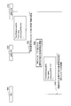
- FIG. 8 is a diagram showing a sequence of distribution processing 1 at a reference time.
- the gNB-CU210 transmits a request signal to the gNB-DU230 in order to request information on the reference time from the gNB-DU230 (S21).
- the gNB-DU230 transmits the reference SFN and the reference time in the gNB-DU230 associated with the reference SFN to the gNB-CU210 in response to the reception of the request signal (S23).
- the reference SFN XXX is transmitted as the reference SFN
- the reference time aaaa is transmitted as the Time.
- the gNB-CU210 sets the reference SFN transmitted from the gNB-DU230 in the referenceSFN of the information element TimeReferenceInfoList in the RRC message addressed to the UE100, and sets the Time of the information element TimeReferenceInfoList to the reference time transmitted from the gNB-DU230. Is set (S25).
- the reference SFN XXX is set in the referenceSFN of the information element TimeReferenceInfoList in the DLInformationTransfer message, and the reference time aaaa is set in the time of the information element TimeReferenceInfoList.
- the gNB-CU210 encodes the RRC message and transmits the RRC message including the reference SFN and the reference time transmitted from the gNB-DU230 to the UE100 via the gNB-DU230 (S27).
- the UE100 When the UE100 receives the RRC message, it may notify the gNB-CU210 of an acknowledgment signal (ACK) via the gNB-DU230.
- ACK acknowledgment signal
- FIG. 9 is a diagram showing a sequence of the delivery process 2 at the reference time.
- the gNB-CU210 sends a message creation instruction to the gNB-DU230 in order to instruct the gNB-DU230 to compose an RRC message addressed to the UE100 (S31).
- the gNB-CU 210 notifies the predetermined information for the gNB-DU 230 to communicate with the UE 100 together with the message creation instruction.
- Predetermined information includes the following information elements: Transaction ID, Cyphering Algorithm, KEY (Security Key), BEAER (Bearer Identity-1), COUNT (HFN + PDCP SN), DIRECTION (0 for uplink and 1 for downlink). ), And LENGTH.
- the gNB-CU210 notifies the gNB-DU230 of all or part of the above-mentioned information elements as predetermined information. It is self-evident that DIRECTION is set to 1 because RRC messages are sent on the downlink. Therefore, the DIRECTION notification may be omitted.
- the length of the coded data is set in LENGTH. Since the gNB-DU230 can also identify the length of the encoded data, the LENGTH notification may be omitted.
- the Cyphering Algorithm and the KEY are information that is used to encode the RRC message and is uniquely determined between the UE 100 and the gNB-CU 210. Therefore, in order for the UE100 to succeed in decoding the RRC message, the gNB-DU230 uses the Cyphering Algorithm and KEY (Security Key) uniquely determined between the UE100 and the gNB-CU210 to obtain the RRC message. Need to be encoded. Therefore, the gNB-CU210 needs to notify the gNB-DU230 of at least the Cyphering Algorithm and the KEY (Security Key).
- the gNB-DU230 sets an RRC message addressed to UE100 in response to receiving a message creation instruction.
- gNB-DU230 sets the reference SFN in the referenceSFN of the information element TimeReferenceInfoList in the RRC message, and sets the reference time in the gNB-DU230 in the Time of the information element TimeReferenceInfoList (S33).
- the reference SFN XXX is set as the reference SFN
- the reference time aaaa is set as the Time.
- the gNB-DU230 encodes the RRC message based on the predetermined information and sends the RRC message including the reference SFN and the reference time to the UE100 (S35).
- the UE100 When the UE100 receives the RRC message, it may notify the gNB-CU210 of an acknowledgment signal (ACK) via the gNB-DU230.
- ACK acknowledgment signal
- FIG. 10 is a diagram showing a sequence of the delivery process 3 at the reference time.
- the gNB-CU210 notifies the gNB-DU230 of a request signal requesting rewriting of the TimeReferenceInfoList, a coded RRC message addressed to the UE100, and predetermined information for the gNB-DU230 to communicate with the UE100 (S41). ).
- the reference SFN of the information element TimeReferenceInfoList in the RRC message is set to the reference SFN, and the time of the information element TimeReferenceInfoList is set to the reference time in the gNB-CU210 associated with the reference SFN.
- the reference SFN XXX is set as the reference SFN
- the reference time aaaa is set as the Time.
- gNB-DU230 When gNB-DU230 receives an RRC message, it decodes the RRC message. gNB-DU230 updates the reference SFN set in the referenceSFN of the information element TimeReferenceInfoList in the RRC message, and also updates the reference time set in the Time of the information element TimeReferenceInfoList (S43). In the present embodiment, the reference SFN XXX set in the reference SFN is updated to YYY, and the reference time aaa set in Time is updated to bbbb.
- the gNB-DU230 encodes the RRC message based on the predetermined information and sends the RRC message including the updated reference SFN and the reference time to the UE100 (S45).
- the UE100 When the UE100 receives the RRC message, it may notify the gNB-CU210 of an acknowledgment signal (ACK) via the gNB-DU230.
- ACK acknowledgment signal
- the reference time may be delivered to UE100.
- the gNB 200 connects a gNB-DU230 that communicates with the UE100 and a gNB-CU210 that is connected to the gNB-DU230 and communicates with the UE100 via the gNB-DU230. Including.
- the gNB-CU210 is provided with a transmission unit 211 that transmits a request signal to the gNB-DU230.
- the gNB-DU230 sets the reference SFN and the reference time of at least one of the NR time and the TSN time associated with the reference SFN based on the reception unit 233 that receives the request signal and the received request signal. -Equipped with a transmitter 231 to transmit to the CU210.
- the transmission unit 211 of the gNB-CU210 transmits an RRC message including the reference SFN and the reference time to the UE 100 via the gNB-DU230.
- gNB200 can deliver an accurate reference time to UE100.
- the gNB-CU210 sends an RRC message as before, so changes to the conventional gNB-CU210 configuration can be minimized. Furthermore, it is no longer necessary to set the reference SFN and information other than the reference time associated with the reference SFN in the gNB-DU230.
- the gNB 200 includes a gNB-DU230 that communicates with the UE100 and a gNB-CU210 that is connected to the gNB-DU230 and communicates with the UE100 via the gNB-DU230.
- the gNB-CU210 is provided with a transmission unit 211 that transmits predetermined information for communicating with the UE100 to the gNB-DU230.
- the gNB-DU230 includes a receiving unit 233 that receives predetermined information, a reference SFN, and a control unit 235 that sets an RRC message including at least one of the NR time and TSN time associated with the reference SFN. , A transmission unit 231 that transmits a set RRC message to the UE 100 based on the received predetermined information.
- gNB200 can deliver an accurate reference time to UE100.
- the gNB 200 includes a gNB-DU230 that communicates with the UE100 and a gNB-CU210 that is connected to the gNB-DU230 and communicates with the UE100 via the gNB-DU230.
- the gNB-CU210 contains an RRC message including predetermined information for communicating with the UE 100, a reference SFN, and at least one reference time of the NR time and the TSN time associated with the reference SFN, gNB-DU230. It is provided with a transmission unit 211 for transmitting to.
- the gNB-DU230 is updated based on the receiving unit 233 that receives the predetermined information and the RRC message, the control unit 235 that updates the reference SFN and the reference time included in the received RRC message, and the received predetermined information. It includes a transmitter 231 that transmits an RRC message including a reference SFN and a reference time to the UE 100.
- gNB200 can deliver an accurate reference time to UE100.
- only gNB-DU230 performs time synchronization based on at least one reference time of NR time and TSN time.
- the gNB200 can deliver a more accurate reference time to the UE100.
- each functional block may be realized by using one device that is physically or logically connected, or directly or indirectly (for example, by using two or more physically or logically separated devices). , Wired, wireless, etc.) and may be realized using these plurality of devices.
- the functional block may be realized by combining the software with the one device or the plurality of devices.
- Functions include judgment, decision, judgment, calculation, calculation, processing, derivation, investigation, search, confirmation, reception, transmission, output, access, solution, selection, selection, establishment, comparison, assumption, expectation, deemed, and notification (There are, but are not limited to, broadcasting, notifying, communicating, forwarding, configuring, reconfiguring, allocating, mapping, assigning, etc. ..
- a functional block that makes transmission function is called a transmitting unit or a transmitter.
- the method of realizing each is not particularly limited.
- FIG. 11 is a diagram showing an example of the hardware configuration of the device. As shown in FIG. 11, the device may be configured as a computer device including a processor 1001, a memory 1002, a storage 1003, a communication device 1004, an input device 1005, an output device 1006, a bus 1007, and the like.
- the word “device” can be read as a circuit, device, unit, etc.
- the hardware configuration of the device may be configured to include one or more of each of the devices shown in the figure, or may be configured not to include some of the devices.
- Each functional block of the device is realized by any hardware element of the computer device or a combination of the hardware elements.
- the processor 1001 performs the calculation, controls the communication by the communication device 1004, and the memory. It is realized by controlling at least one of reading and writing of data in 1002 and storage 1003.
- Processor 1001 operates, for example, an operating system to control the entire computer.
- the processor 1001 may be composed of a central processing unit (CPU) including an interface with peripheral devices, a control device, an arithmetic unit, registers, and the like.
- CPU central processing unit
- the processor 1001 reads a program (program code), a software module, data, etc. from at least one of the storage 1003 and the communication device 1004 into the memory 1002, and executes various processes according to these.
- a program program code
- a program that causes a computer to execute at least a part of the operations described in the above-described embodiment is used.
- the various processes described above may be executed by one processor 1001 or may be executed simultaneously or sequentially by two or more processors 1001.
- Processor 1001 may be implemented by one or more chips.
- the program may be transmitted from the network via a telecommunication line.
- the memory 1002 is a computer-readable recording medium, and is composed of at least one of, for example, ReadOnlyMemory (ROM), ErasableProgrammableROM (EPROM), Electrically ErasableProgrammableROM (EEPROM), RandomAccessMemory (RAM), and the like. May be done.
- the memory 1002 may be called a register, a cache, a main memory (main storage device), or the like.
- the memory 1002 can store a program (program code), a software module, or the like that can execute the method according to the embodiment of the present disclosure.
- the storage 1003 is a computer-readable recording medium, for example, an optical disk such as a Compact Disc ROM (CD-ROM), a hard disk drive, a flexible disk, a photomagnetic disk (for example, a compact disk, a digital versatile disk, a Blu-ray). It may consist of at least one (registered trademark) disk), smart card, flash memory (eg, card, stick, key drive), floppy (registered trademark) disk, magnetic strip, and the like.
- Storage 1003 may be referred to as auxiliary storage.
- the recording medium described above may be, for example, a database, server or other suitable medium containing at least one of memory 1002 and storage 1003.
- the communication device 1004 is hardware (transmission / reception device) for communicating between computers via at least one of a wired network and a wireless network, and is also referred to as, for example, a network device, a network controller, a network card, a communication module, or the like.
- Communication device 1004 includes, for example, a high frequency switch, a duplexer, a filter, a frequency synthesizer, etc. in order to realize at least one of frequency division duplex (FDD) and time division duplex (TDD). It may be composed of.
- FDD frequency division duplex
- TDD time division duplex
- the input device 1005 is an input device (for example, keyboard, mouse, microphone, switch, button, sensor, etc.) that accepts input from the outside.
- the output device 1006 is an output device (for example, a display, a speaker, an LED lamp, etc.) that outputs to the outside.
- the input device 1005 and the output device 1006 may have an integrated configuration (for example, a touch panel).
- each device such as the processor 1001 and the memory 1002 is connected by the bus 1007 for communicating information.
- the bus 1007 may be configured by using a single bus, or may be configured by using a different bus for each device.
- the device includes hardware such as a microprocessor, a digital signal processor (Digital Signal Processor: DSP), an Application Specific Integrated Circuit (ASIC), a Programmable Logic Device (PLD), and a Field Programmable Gate Array (FPGA).
- the hardware may implement some or all of each functional block.
- processor 1001 may be implemented using at least one of these hardware.
- information notification includes physical layer signaling (for example, Downlink Control Information (DCI), Uplink Control Information (UCI), upper layer signaling (eg, RRC signaling, Medium Access Control (MAC) signaling, broadcast information (Master Information Block)). (MIB), System Information Block (SIB)), other signals or combinations thereof.
- DCI Downlink Control Information
- UCI Uplink Control Information
- RRC signaling may also be referred to as an RRC message, for example, RRC Connection Setup. ) Message, RRC Connection Reconfiguration message, etc. may be used.
- LTE LongTermEvolution
- LTE-A LTE-Advanced
- SUPER3G IMT-Advanced
- 4G 4th generation mobile communication system
- 5G 5th generation mobile communication system
- FutureRadioAccess FAA
- NewRadio NR
- W-CDMA registered trademark
- GSM registered trademark
- CDMA2000 Code Division Multiple Access 2000
- UMB UltraMobile Broadband
- IEEE802.11 Wi-Fi (registered trademark)
- IEEE802.16 WiMAX®
- IEEE802.20 Ultra-WideBand (UWB), Bluetooth®, and other systems that utilize appropriate systems and at least one of the next generation systems extended based on them.
- a plurality of systems may be applied in combination (for example, a combination of at least one of LTE and LTE-A and 5G).
- the specific operation performed by the base station in the present disclosure may be performed by its upper node (upper node).
- various operations performed for communication with a terminal are performed by the base station and other network nodes other than the base station (for example, MME or). It is clear that it can be done by at least one of (but not limited to, S-GW, etc.).
- S-GW network node
- the case where there is one network node other than the base station is illustrated above, it may be a combination of a plurality of other network nodes (for example, MME and S-GW).
- Information and signals can be output from the upper layer (or lower layer) to the lower layer (or upper layer).
- Input / output may be performed via a plurality of network nodes.
- the input / output information may be stored in a specific location (for example, memory) or may be managed using a management table.
- the input / output information can be overwritten, updated, or added.
- the output information may be deleted.
- the input information may be transmitted to another device.
- the determination may be made by a value represented by 1 bit (0 or 1), by a boolean value (Boolean: true or false), or by comparing numerical values (for example, a predetermined value). It may be done by comparison with the value).
- the notification of predetermined information (for example, the notification of "being X") is not limited to the explicit one, but is performed implicitly (for example, the notification of the predetermined information is not performed). May be good.
- Software is an instruction, instruction set, code, code segment, program code, program, subprogram, software module, whether called software, firmware, middleware, microcode, hardware description language, or another name.
- Applications, software applications, software packages, routines, subroutines, objects, executable files, execution threads, procedures, functions, etc. should be broadly interpreted to mean.
- software, instructions, information, etc. may be transmitted and received via a transmission medium.
- a transmission medium For example, a website, where the software uses at least one of wired technology (coaxial cable, fiber optic cable, twist pair, Digital Subscriber Line (DSL), etc.) and wireless technology (infrared, microwave, etc.).
- wired technology coaxial cable, fiber optic cable, twist pair, Digital Subscriber Line (DSL), etc.
- wireless technology infrared, microwave, etc.
- the information, signals, etc. described in this disclosure may be represented using any of a variety of different techniques.
- data, instructions, commands, information, signals, bits, symbols, chips, etc. that may be referred to throughout the above description are voltages, currents, electromagnetic waves, magnetic fields or magnetic particles, light fields or photons, or any of these. It may be represented by a combination of.
- a channel and a symbol may be a signal (signaling).
- the signal may be a message.
- the component carrier (CC) may be referred to as a carrier frequency, a cell, a frequency carrier, or the like.
- system and “network” used in this disclosure are used interchangeably.
- the information, parameters, etc. described in the present disclosure may be expressed using absolute values, relative values from predetermined values, or using other corresponding information. It may be represented.
- the radio resource may be one indicated by an index.
- Base Station BS
- Wireless Base Station Wireless Base Station
- NodeB NodeB
- eNodeB eNodeB
- gNodeB gNodeB
- Base stations are sometimes referred to by terms such as macrocells, small cells, femtocells, and picocells.
- the base station can accommodate one or more (for example, three) cells (also called sectors). When a base station accommodates multiple cells, the entire coverage area of the base station can be divided into multiple smaller areas, each smaller area being a base station subsystem (eg, a small indoor base station (Remote Radio)). Communication services can also be provided by Head: RRH).
- a base station subsystem eg, a small indoor base station (Remote Radio)
- Communication services can also be provided by Head: RRH).
- cell refers to a base station that provides communication services in this coverage, and part or all of the coverage area of at least one of the base station subsystems.
- MS mobile station
- UE user equipment
- terminal terminal
- Mobile stations can be subscriber stations, mobile units, subscriber units, wireless units, remote units, mobile devices, wireless devices, wireless communication devices, remote devices, mobile subscriber stations, access terminals, mobile terminals, wireless, depending on the trader. It may also be referred to as a terminal, remote terminal, handset, user agent, mobile client, client, or some other suitable term.
- At least one of the base station and the mobile station may be called a transmitting device, a receiving device, a communication device, or the like.
- At least one of the base station and the mobile station may be a device mounted on the mobile body, the mobile body itself, or the like.
- the moving body may be a vehicle (eg, car, airplane, etc.), an unmanned moving body (eg, drone, self-driving car, etc.), or a robot (manned or unmanned). ) May be.
- at least one of the base station and the mobile station includes a device that does not necessarily move during communication operation.
- at least one of a base station and a mobile station may be an Internet of Things (IoT) device such as a sensor.
- IoT Internet of Things
- the base station in the present disclosure may be read as a mobile station (user terminal, the same applies hereinafter).
- communication between a base station and a mobile station has been replaced with communication between a plurality of mobile stations (for example, it may be called Device-to-Device (D2D), Vehicle-to-Everything (V2X), etc.).
- D2D Device-to-Device
- V2X Vehicle-to-Everything
- Each aspect / embodiment of the present disclosure may be applied to the configuration.
- the mobile station may have the function of the base station.
- words such as "up” and “down” may be read as words corresponding to inter-terminal communication (for example, "side").
- the uplink, downlink, and the like may be read as side channels.
- the mobile station in the present disclosure may be read as a base station.
- the base station may have the functions of the mobile station.
- connection means any direct or indirect connection or connection between two or more elements, and each other. It can include the presence of one or more intermediate elements between two “connected” or “combined” elements.
- the connection or connection between the elements may be physical, logical, or a combination thereof.
- connection may be read as "access”.
- the two elements use at least one of one or more wires, cables and printed electrical connections, and, as some non-limiting and non-comprehensive examples, the radio frequency domain.
- Electromagnetic energies with wavelengths in the microwave and light (both visible and invisible) regions, etc. can be considered to be “connected” or “coupled” to each other.
- the reference signal can also be abbreviated as Reference Signal (RS), and may be called a pilot (Pilot) depending on the applicable standard.
- RS Reference Signal
- Pilot pilot
- references to elements using designations such as “first”, “second” as used in this disclosure does not generally limit the quantity or order of those elements. These designations can be used in the present disclosure as a convenient way to distinguish between two or more elements. Thus, references to the first and second elements do not mean that only two elements can be adopted there, or that the first element must somehow precede the second element.
- the term "A and B are different” may mean “A and B are different from each other”.
- the term may mean that "A and B are different from C”.
- Terms such as “separate” and “combined” may be interpreted in the same way as “different”.
- radio base station According to the radio base station described above, it is useful in HLS because it can deliver an accurate reference time to the user device.
Abstract
A gNB (200) includes a gNB-DU (230) communicating with a UE (100), and a gNB-CU (210) connected to the gNB-DU (230) and communicating with the UE (100) via the gNB-DU (230). The gNB-CU (210) is provided with a transmission unit (211) for transmitting a request signal to the gNB-DU (230). The gNB-DU (230) is provided with a reception unit (233) for receiving the request signal, and a transmission unit (231) for transmitting a reference system frame number and a reference time of day in a prescribed network that is associated with the reference system frame number to the gNB-CU (210) on the basis of the received request signal. The transmission unit (211) of the gNB-CU (210) transmits a wireless resource control (RRC) message that includes the reference system frame number and the reference time of day to the UE (100) via the gNB-DU (230).
Description
本発明は、基準時刻を配信する無線基地局に関する。
The present invention relates to a radio base station that delivers a reference time.
3rd Generation Partnership Project(3GPP)は、Long Term Evolution(LTE)を仕様化し、LTEのさらなる高速化を目的としてLTE-Advanced(以下、LTE-Advancedを含めてLTEという)を仕様化している。また、3GPPでは、さらに、5G New Radio(NR)などと呼ばれるLTEの後継システムの仕様が検討されている。
The 3rd Generation Partnership Project (3GPP) has specified Long Term Evolution (LTE), and has specified LTE-Advanced (hereinafter referred to as LTE including LTE-Advanced) for the purpose of further speeding up LTE. In addition, 3GPP is also considering the specifications of LTE successor systems such as 5G New Radio (NR).
産業用のInternet of things(IIoT)において、Time-Sensitive Networking(TSN)に対応するために、NRシステム内で、無線基地局(gNB)が、NRシステム及びTSNのうちの少なくとも一方で適用されている基準時刻を、ユーザ装置(UE)に配信することが検討されている(非特許文献1参照)。これにより、UEは、当該基準時刻に基づいて、時刻同期を行うことができる。
In the Industrial Internet of Things (IIoT), in order to support Time-Sensitive Networking (TSN), a radio base station (gNB) is applied in at least one of the NR system and TSN in the NR system. It is being considered to deliver the reference time to the user device (UE) (see Non-Patent Document 1). As a result, the UE can perform time synchronization based on the reference time.
非特許文献1では、gNBが、ブロードキャスト無線リソース制御(RRC)シグナリング及びユニキャストRRCシグナリングのうち、少なくとも一方のRRCシグナリングを用いて、基準時刻をUEに配信することが議論されている。
Non-Patent Document 1 discusses that gNB uses at least one of broadcast radio resource control (RRC) signaling and unicast RRC signaling to deliver a reference time to the UE.
一方、NRシステム内において、gNBは、Central Unit(gNB-CU)と、gNB-CUの設置場所から張り出して遠隔に配置されるDistributed Unit(gNB-DU)とに分離されている。
On the other hand, in the NR system, gNB is separated into a Central Unit (gNB-CU) and a Distributed Unit (gNB-DU) that projects from the installation location of the gNB-CU and is located remotely.
このような構成を有するgNBにおいて、NRでは、gNB-DUに無線リンク制御レイヤ(RLC)などの下位レイヤが備えられ、gNB-CUにパケット・データ・コンバージェンス・プロトコル・レイヤ(PDCP)以上の上位レイヤが備えられる、いわゆるCU-DUのHigher Layer Split(HLS)が規定されている。
In gNB having such a configuration, in NR, gNB-DU is provided with a lower layer such as a wireless link control layer (RLC), and gNB-CU is higher than the packet data convergence protocol layer (PDCP). The so-called CU-DU Higher Layer Split (HLS) that has layers is specified.
HLSにおいて、RRCシグナリングの送信はgNB-CUで行われる。
In HLS, RRC signaling is transmitted by gNB-CU.
しかしながら、NRシステムにおいて、gNB-CUが、RRCシグナリングを用いて、基準時刻をUEに配信する場合、gNB-CU及びgNB-DUは、互いに物理的に離れているため、gNB-CUとgNB-DUとの間において配信遅延が生じる可能性がある。
However, in an NR system, when gNB-CU uses RRC signaling to deliver the reference time to the UE, gNB-CU and gNB-DU are physically separated from each other, so gNB-CU and gNB- Delivery delays may occur with the DU.
この場合、gNBは、正確な基準時刻をUEに配信できない。
In this case, gNB cannot deliver the exact reference time to the UE.
そこで、本発明は、このような状況に鑑みてなされたものであり、HLSにおいて、ユーザ装置に対して、正確な基準時刻を配信し得る無線基地局を提供することを目的とする。
Therefore, the present invention has been made in view of such a situation, and an object of the present invention is to provide a wireless base station capable of delivering an accurate reference time to a user device in HLS.
本発明の一態様に係る無線基地局(200)は、所定のユーザ装置(100)と通信を行う第1通信装置(230)と、前記第1通信装置(230)と接続され、前記第1通信装置(230)を介して前記所定のユーザ装置(100)と通信を行う第2通信装置(210)とを含み、前記第2通信装置(210)は、要求信号を前記第1通信装置(230)に送信する送信部(211)を備え、前記第1通信装置(230)は、前記要求信号を受信する受信部(233)と、受信した要求信号に基づいて、基準システムフレーム番号と、前記基準システムフレーム番号に関連づけられた所定ネットワーク内の基準時刻とを、前記第2通信装置(210)に送信する送信部(231)と、を備え、前記第2通信装置(210)の送信部(211)は、前記基準システムフレーム番号及び前記基準時刻を含む無線リソース制御メッセージを、前記第1通信装置(230)を介して前記所定のユーザ装置(100)に送信する。
The radio base station (200) according to one aspect of the present invention is connected to a first communication device (230) that communicates with a predetermined user device (100) and the first communication device (230), and the first communication device (230) is connected. The second communication device (210) includes a second communication device (210) that communicates with the predetermined user device (100) via the communication device (230), and the second communication device (210) sends a request signal to the first communication device (210). The first communication device (230) includes a transmitting unit (211) for transmitting to the 230), a receiving unit (233) for receiving the request signal, and a reference system frame number and a reference system frame number based on the received request signal. A transmission unit (231) for transmitting a reference time in a predetermined network associated with the reference system frame number to the second communication device (210) is provided, and a transmission unit of the second communication device (210) is provided. (211) transmits a radio resource control message including the reference system frame number and the reference time to the predetermined user device (100) via the first communication device (230).
本発明の一態様に係る無線基地局(200)は、所定のユーザ装置(100)と通信を行う第1通信装置(230)と、前記第1通信装置(230)と接続され、前記第1通信装置(230)を介して前記所定のユーザ装置(100)と通信を行う第2通信装置(210)とを含み、前記第2通信装置(210)は、前記所定のユーザ装置(100)と通信を行うための所定情報を、前記第1通信装置(230)に送信する送信部(211)を備え、前記第1通信装置(230)は、前記所定情報を受信する受信部(233)と、基準システムフレーム番号と、前記基準システムフレーム番号に関連づけられた所定ネットワーク内の基準時刻とを含む無線リソース制御(RRC)メッセージを設定する制御部(235)と、受信した前記所定情報に基づいて、設定された前記RRCメッセージを前記所定のユーザ装置(100)に送信する送信部(231)と、を備える。
The radio base station (200) according to one aspect of the present invention is connected to a first communication device (230) that communicates with a predetermined user device (100) and the first communication device (230), and the first communication device (230) is connected. The second communication device (210) includes the second communication device (210) that communicates with the predetermined user device (100) via the communication device (230), and the second communication device (210) is the same as the predetermined user device (100). The first communication device (230) includes a transmission unit (211) for transmitting predetermined information for communication to the first communication device (230), and the first communication device (230) has a receiving unit (233) for receiving the predetermined information. , Based on the control unit (235) that sets the radio resource control (RRC) message including the reference system frame number and the reference time in the predetermined network associated with the reference system frame number, and the received predetermined information. , A transmission unit (231) for transmitting the set RRC message to the predetermined user device (100).
本発明の一態様に係る無線基地局(200)は、所定のユーザ装置(100)と通信を行う第1通信装置(230)と、前記第1通信装置(230)と接続され、前記第1通信装置(230)を介して前記所定のユーザ装置(100)と通信を行う第2通信装置(210)とを含み、前記第2通信装置(210)は、前記所定のユーザ装置(100)と通信を行うための所定情報と、基準システムフレーム番号と前記基準システムフレーム番号に関連づけられた所定ネットワーク内の基準時刻とを含む無線リソース制御(RRC)メッセージとを、第1通信装置(230)に送信する送信部(211)を備え、前記第1通信装置(230)は、前記所定情報及びRRCメッセージを受信する受信部(233)と、受信した前記RRCメッセージに含まれる、前記基準システムフレーム番号及び前記基準時刻を更新する制御部(235)と、受信した前記所定情報に基づいて、更新された前記基準システムフレーム番号及び前記基準時刻を含む前記RRCメッセージを、前記所定のユーザ装置(100)に送信する送信部(231)と、を備える。
The radio base station (200) according to one aspect of the present invention is connected to a first communication device (230) that communicates with a predetermined user device (100) and the first communication device (230), and the first communication device (230) is connected. The second communication device (210) includes the second communication device (210) that communicates with the predetermined user device (100) via the communication device (230), and the second communication device (210) is the same as the predetermined user device (100). A radio resource control (RRC) message including a predetermined information for communication and a reference system frame number and a reference time in a predetermined network associated with the reference system frame number is sent to the first communication device (230). The first communication device (230) includes a transmission unit (211) for transmission, the reception unit (233) for receiving the predetermined information and the RRC message, and the reference system frame number included in the received RRC message. And the control unit (235) that updates the reference time, and the RRC message including the updated reference system frame number and the reference time based on the received predetermined information, the predetermined user apparatus (100). It is provided with a transmission unit (231) for transmitting to.
以下、実施形態を図面に基づいて説明する。なお、同一の機能や構成には、同一又は類似の符号を付して、その説明を適宜省略する。
Hereinafter, embodiments will be described based on the drawings. The same functions and configurations are designated by the same or similar reference numerals, and the description thereof will be omitted as appropriate.
(1)遠隔制御システムの全体概略構成
図1は、実施形態に係る遠隔制御システム10の全体概略構成図である。 (1) Overall Schematic Configuration of Remote Control System FIG. 1 is an overall schematic configuration diagram of theremote control system 10 according to the embodiment.
図1は、実施形態に係る遠隔制御システム10の全体概略構成図である。 (1) Overall Schematic Configuration of Remote Control System FIG. 1 is an overall schematic configuration diagram of the
遠隔制御システム10は、TSNグランドマスター(TSN GM)20と、NRシステム30と、エンドステーション40とを含む。遠隔制御システム10では、TSNの制御元(図示略)が、NRシステム30を経由して、TSNのエンドステーション40をリアルタイムで遠隔制御する。なお、gNB及びUEの数を含む遠隔制御システム10の具体的な構成は、図1に示した例に限定されない。
The remote control system 10 includes a TSN grand master (TSNGM) 20, an NR system 30, and an end station 40. In the remote control system 10, the TSN control source (not shown) remotely controls the TSN end station 40 in real time via the NR system 30. The specific configuration of the remote control system 10 including the number of gNBs and UEs is not limited to the example shown in FIG.
TSN GM20は、TSN時刻を生成するためのクロックを高精度に発振する。以後、TSN GM20が発振するクロックに基づいて生成される時刻をTSN時刻と呼ぶ。TSN時刻は、TSN内で適用される基準時刻である。
The TSN GM20 oscillates the clock for generating the TSN time with high accuracy. Hereinafter, the time generated based on the clock oscillated by the TSN GM20 is referred to as the TSN time. The TSN time is the reference time applied within the TSN.
遠隔制御システム10では、リアルタイムでの遠隔制御を実現するために、TSNの制御元の時刻及びエンドステーション40の時刻を、TSN時刻に合せる必要がある。
In the remote control system 10, in order to realize remote control in real time, it is necessary to match the time of the TSN control source and the time of the end station 40 with the TSN time.
NRシステム30は、NRグランドマスター(NR GM)31と、UE100と、gNB200と、コアネットワーク300とを含む。
The NR system 30 includes the NR grandmaster (NR GM) 31, UE100, gNB200, and core network 300.
NR GM31は、NRシステム30の動作タイミングとなるクロックを発振する。以後、NR GM31が発振するクロックに基づいて生成される時刻をNR時刻と呼ぶ。NR時刻は、NRシステム30内で適用される基準時刻である。
The NR GM31 oscillates the clock that is the operation timing of the NR system 30. Hereinafter, the time generated based on the clock oscillated by the NR GM31 is referred to as the NR time. The NR time is the reference time applied within the NR system 30.
UE100は、UE100とgNB200及びコアネットワーク300との間においてNRに従った無線通信を実行する。UE100は、基準時刻としてNR時刻を含むブロードキャストRRCシグナリング及びユニキャストRRCシグナリングのうち、少なくとも一方のRRCシグナリングを、gNB200から受信する。UE100は、TSNに対応するために、受信したNR時刻に基づいて、時刻同期を行う。
UE100 executes wireless communication according to NR between UE100 and gNB200 and core network 300. The UE100 receives at least one of the broadcast RRC signaling and the unicast RRC signaling including the NR time as the reference time from the gNB200. The UE100 synchronizes the time based on the received NR time in order to support TSN.
gNB200は、gNB200とコアネットワーク300との間においてNRに従った無線通信を実行する。gNB200は、Central Unit(gNB-CU)210と、Distributed Unit(gNB-DU)230とによって構成される。gNB-CU210は、コアネットワーク300側に配置され、gNB-DU230を制御する。gNB-CU210は、複数のgNB-DU230を制御してもよい。gNB-DU230は、UE100側に配置される。
The gNB200 executes wireless communication according to NR between the gNB200 and the core network 300. The gNB200 is composed of a Central Unit (gNB-CU) 210 and a Distributed Unit (gNB-DU) 230. The gNB-CU210 is located on the core network 300 side and controls the gNB-DU230. The gNB-CU210 may control a plurality of gNB-DU230s. gNB-DU230 is located on the UE100 side.
gNB-CU210は、F1インタフェース(例えば、光ファイバ)を介してgNB-DU230に接続される。gNB-CU210は、gNB-DU230を介して、UE100と通信を行う。なお、gNB-CU210とgNB-DU230との間において、ハブ、ルータなどを設置することができる。
The gNB-CU210 is connected to the gNB-DU230 via an F1 interface (for example, an optical fiber). The gNB-CU210 communicates with the UE 100 via the gNB-DU230. A hub, router, etc. can be installed between the gNB-CU210 and gNB-DU230.
gNB200において、少なくともgNB-DU230が、NR時刻に基づいて、時刻同期を行う。なお、gNB-DU230のみが、NR時刻に基づいて、時刻同期を行ってもよい。
In gNB200, at least gNB-DU230 performs time synchronization based on the NR time. Note that only gNB-DU230 may perform time synchronization based on the NR time.
gNB200は、後述するように、基準時刻としてNR時刻を含むブロードキャストRRCシグナリング及びユニキャストRRCシグナリングのうち、少なくとも一方のRRCシグナリングを、UE100に送信する。
As will be described later, the gNB 200 transmits at least one of the broadcast RRC signaling and the unicast RRC signaling including the NR time as the reference time to the UE 100.
UE100及びgNB200は、複数のアンテナ素子から送信される無線信号を制御することによって、より指向性の高いビームを生成するMassive MIMO、複数のコンポーネントキャリア(CC)を用いるキャリアアグリゲーション(CA)、及び複数のgNBとUEとの間においてコンポーネントキャリアを同時送信するデュアルコネクティビティ(DC)などに対応することができる。
UE100 and gNB200 include Massive MIMO, which generates a more directional beam by controlling radio signals transmitted from multiple antenna elements, carrier aggregation (CA) using multiple component carriers (CC), and multiple carriers. It is possible to support dual connectivity (DC) in which component carriers are transmitted simultaneously between gNB and UE.
コアネットワーク300は、gNB200を介して、UE100と通信する。コアネットワーク300は、User Plane Function(UPF)310を有する。UPF310は、U-plane処理に特化した機能を提供する。
The core network 300 communicates with the UE 100 via the gNB 200. The core network 300 has a User Plane Function (UPF) 310. UPF310 provides functions specialized for U-plane processing.
UPF310はTSN GM20に接続される。なお、図2に示すように、遠隔制御システム10aにおいて、TSN GM20は、UPF310の代わりに、gNB200に接続されてもよい。この場合、gNB200は、基準時刻としてTSN時刻を含むブロードキャストRRCシグナリング及びユニキャストRRCシグナリングのうち、少なくとも一方のRRCシグナリングを、UE100に送信することができる。UE100は、TSNに対応するために、受信したTSN時刻に基づいて、時刻同期を行う。
UPF310 is connected to TSN GM20. As shown in FIG. 2, in the remote control system 10a, the TSN GM20 may be connected to the gNB 200 instead of the UPF310. In this case, the gNB 200 can transmit at least one of the broadcast RRC signaling and the unicast RRC signaling including the TSN time as the reference time to the UE 100. UE100 performs time synchronization based on the received TSN time in order to support TSN.
この場合、gNB200において、少なくともgNB-DU230が、NR時刻及びTSN時刻のうち、少なくとも一方の基準時刻に基づいて、時刻同期を行う。なお、gNB-DU230のみが、基準時刻に基づいて、時刻同期を行ってもよい。
In this case, in gNB200, at least gNB-DU230 synchronizes the time based on at least one reference time of NR time and TSN time. Note that only gNB-DU230 may perform time synchronization based on the reference time.
なお、この場合、gNB200は、基準時刻としてNR時刻及びTSN時刻を含むブロードキャストRRCシグナリング及びユニキャストRRCシグナリングのうち、少なくとも一方のRRCシグナリングを、UE100に送信してもよい。UE100は、TSNに対応するために、受信したNR時刻及びTSN時刻のうち、少なくとも一方の基準時刻に基づいて、時刻同期を行ってもよい。
In this case, the gNB 200 may transmit at least one of the broadcast RRC signaling and the unicast RRC signaling including the NR time and the TSN time as the reference time to the UE 100. The UE 100 may perform time synchronization based on at least one reference time of the received NR time and TSN time in order to correspond to the TSN.
エンドステーション40は、生産工場内に設けられる機械(例えば、ロボットアーム)である。エンドステーション40は、NRシステム30を介して、TSNの制御元からの指令を受信する。TSNの制御元は、TSN時刻に基づいて、エンドステーション40を動作させるための時間スケジューリングを行うことにより、遠隔制御システム10において、リアルタイムな遠隔制御が実行される。
The end station 40 is a machine (for example, a robot arm) installed in the production factory. The end station 40 receives a command from the TSN control source via the NR system 30. The control source of the TSN performs real-time remote control in the remote control system 10 by performing time scheduling for operating the end station 40 based on the TSN time.
(2)gNBのプロトコルスタック
次に、gNB200のプロトコルスタックを説明する。図3は、gNB200のプロトコルスタックを示す。図3に示すように、gNB200は、gNB-CU210及びgNB-DU230を含む。 (2) gNB protocol stack Next, the gNB200 protocol stack will be described. FIG. 3 shows the protocol stack of gNB200. As shown in FIG. 3, gNB200 includes gNB-CU210 and gNB-DU230.
次に、gNB200のプロトコルスタックを説明する。図3は、gNB200のプロトコルスタックを示す。図3に示すように、gNB200は、gNB-CU210及びgNB-DU230を含む。 (2) gNB protocol stack Next, the gNB200 protocol stack will be described. FIG. 3 shows the protocol stack of gNB200. As shown in FIG. 3, gNB200 includes gNB-CU210 and gNB-DU230.
gNB-CU210は、上位レイヤ、具体的には、パケット・データ・コンバージェンス・プロトコル・レイヤ(PDCP)及び無線リソース制御レイヤ(RRC)を提供する。なお、gNB-CU210は、サービス・データ・アダプテーション・プロトコル・レイヤ(SDAP)を提供してもよい。
The gNB-CU210 provides an upper layer, specifically, a packet data convergence protocol layer (PDCP) and a radio resource control layer (RRC). The gNB-CU210 may provide a service data adaptation protocol layer (SDAP).
gNB-CU210は、gNB-DU230の動作を制御する。gNB-CU210は、gNB-DU230とのF1インターフェースを終端(terminate)する。
The gNB-CU210 controls the operation of the gNB-DU230. The gNB-CU210 terminates the F1 interface with the gNB-DU230.
gNB-DU230は、下位レイヤ、具体的には、物理レイヤ(L1)及び無線部(RF)、ミディアムアクセス制御レイヤ(MAC)及び無線リンク制御レイヤ(RLC)を提供する。
The gNB-DU230 provides a lower layer, specifically, a physical layer (L1) and a radio unit (RF), a medium access control layer (MAC), and a radio link control layer (RLC).
gNB-DU230は、UE100と当該下位レイヤを介して通信を実行する。本実施形態において、gNB-DU230は、UE100と無線通信を実行する第1通信装置を構成する。
The gNB-DU230 executes communication with the UE100 via the lower layer. In the present embodiment, the gNB-DU 230 constitutes a first communication device that executes wireless communication with the UE 100.
gNB-DU230は、一または複数のセルをサポートする。一つのセルは、一つのgNB-DUのみによってサポートされる。gNB-DU230は、gNB-CU210とのF1インターフェースを終端(terminate)する。
GNB-DU230 supports one or more cells. One cell is supported by only one gNB-DU. The gNB-DU230 terminates the F1 interface with the gNB-CU210.
このような構成により、gNB-CU210は、gNB-DU230と接続され、RLCなどの下位レイヤよりも上位であるRRCを介してUE100と通信を実行する。本実施形態において、gNB-CU210は、gNB-DU230と接続されて、gNB-DU230を介してUE100と通信を行う第2通信装置を構成する。
With such a configuration, gNB-CU210 is connected to gNB-DU230 and communicates with UE100 via RRC, which is higher than lower layers such as RLC. In the present embodiment, the gNB-CU 210 constitutes a second communication device that is connected to the gNB-DU230 and communicates with the UE 100 via the gNB-DU230.
(3)gNB-CUの機能ブロック構成
次に、gNB-CU210の機能ブロック構成について説明する。以下、本実施形態における特徴に関連する部分についてのみ説明する。したがって、当該gNB-CU210は、本実施形態における特徴に直接関係しない他の機能ブロックを備えることは勿論である。 (3) Functional block configuration of gNB-CU Next, the functional block configuration of gNB-CU210 will be described. Hereinafter, only the parts related to the features in the present embodiment will be described. Therefore, it goes without saying that the gNB-CU210 includes other functional blocks that are not directly related to the features of the present embodiment.
次に、gNB-CU210の機能ブロック構成について説明する。以下、本実施形態における特徴に関連する部分についてのみ説明する。したがって、当該gNB-CU210は、本実施形態における特徴に直接関係しない他の機能ブロックを備えることは勿論である。 (3) Functional block configuration of gNB-CU Next, the functional block configuration of gNB-CU210 will be described. Hereinafter, only the parts related to the features in the present embodiment will be described. Therefore, it goes without saying that the gNB-CU210 includes other functional blocks that are not directly related to the features of the present embodiment.
図4は、gNB-CU210の機能ブロック構成図である。なお、gNB-CU210のハードウェア構成については後述する。図4に示すように、gNB-CU210は、送信部211と、受信部213と、制御部215とを備える。
FIG. 4 is a functional block configuration diagram of gNB-CU210. The hardware configuration of gNB-CU210 will be described later. As shown in FIG. 4, the gNB-CU210 includes a transmission unit 211, a reception unit 213, and a control unit 215.
送信部211は、gNB-DU230に対して、コード化されたシステム情報、コード化されたRRCメッセージ、gNB-DU230から基準時刻に関する情報を要求するための要求信号、TimeReferenceInforListの書き換えを要求するための要求信号、RRCメッセージの作成をgNB-DU230に指示するためのメッセージ作成指示、gNB-DU230がUE100と通信を行うための所定情報などを送信する。
The transmitter 211 requests the gNB-DU230 to rewrite the coded system information, the coded RRC message, the request signal for requesting the information about the reference time from the gNB-DU230, and the TimeReferenceInforList. It sends a request signal, a message creation instruction to instruct the gNB-DU230 to create an RRC message, and predetermined information for the gNB-DU230 to communicate with the UE100.
受信部213は、gNB-DU230から、基準SFN、当該基準SFNに関連付けられた、gNB-DU230における基準時刻などを受信する。
The receiving unit 213 receives the reference SFN, the reference time in the gNB-DU230 associated with the reference SFN, and the like from the gNB-DU230.
制御部215は、システム情報の設定、RRCメッセージの設定、システム情報のコード化、RRCメッセージのコード化などを行う。
Control unit 215 sets system information, sets RRC messages, encodes system information, encodes RRC messages, and so on.
(4)gNB-DUの機能ブロック構成
次に、gNB-DU230の機能ブロック構成について説明する。以下、本実施形態における特徴に関連する部分についてのみ説明する。したがって、当該gNB-DU230は、本実施形態における特徴に直接関係しない他の機能ブロックを備えることは勿論である。 (4) Functional block configuration of gNB-DU Next, the functional block configuration of gNB-DU230 will be described. Hereinafter, only the parts related to the features in the present embodiment will be described. Therefore, it goes without saying that the gNB-DU230 includes other functional blocks that are not directly related to the features of the present embodiment.
次に、gNB-DU230の機能ブロック構成について説明する。以下、本実施形態における特徴に関連する部分についてのみ説明する。したがって、当該gNB-DU230は、本実施形態における特徴に直接関係しない他の機能ブロックを備えることは勿論である。 (4) Functional block configuration of gNB-DU Next, the functional block configuration of gNB-DU230 will be described. Hereinafter, only the parts related to the features in the present embodiment will be described. Therefore, it goes without saying that the gNB-DU230 includes other functional blocks that are not directly related to the features of the present embodiment.
図5は、gNB-DU230の機能ブロック構成図である。なお、gNB-DU230のハードウェア構成については後述する。図5に示すように、gNB-DU230は、送信部231と、受信部233と、制御部235とを備える。
FIG. 5 is a functional block configuration diagram of gNB-DU230. The hardware configuration of gNB-DU230 will be described later. As shown in FIG. 5, the gNB-DU230 includes a transmission unit 231, a reception unit 233, and a control unit 235.
送信部231は、gNB-CU210に対して、基準SFN、当該基準SFNに関連付けられた、gNB-DU230における基準時刻などを送信する。送信部231は、UE100に対して、コード化されたシステム情報、コード化されたRRCメッセージなどを送信する。
The transmission unit 231 transmits the reference SFN, the reference time in the gNB-DU230 associated with the reference SFN, and the like to the gNB-CU210. The transmitter 231 transmits the encoded system information, the encoded RRC message, and the like to the UE 100.
受信部233は、gNB-CU210から、コード化されたシステム情報、コード化されたRRCメッセージ、gNB-DU230から基準時刻に関する情報を要求するための要求信号、TimeReferenceInforListの書き換えを要求するための要求信、RRCメッセージの作成をgNB-DU230に指示するためのメッセージ作成指示、gNB-DU230がUE100と通信を行うための所定情報などを受信する。
The receiver 233 receives a coded system information, a coded RRC message from the gNB-CU210, a request signal for requesting information about the reference time from the gNB-DU230, and a request message for requesting rewriting of the TimeReferenceInforList. , Receives message creation instructions for instructing gNB-DU230 to create RRC messages, and predetermined information for gNB-DU230 to communicate with UE100.
制御部235は、システム情報の更新(書き換え)、RRCメッセージの設定、RRCメッセージの更新(書き換え)、システム情報のデコード、システム情報のコード化、RRCメッセージのコード化などを行う。
Control unit 235 updates (rewrites) system information, sets RRC messages, updates (rewrites) RRC messages, decodes system information, encodes system information, encodes RRC messages, and so on.
(5)NRシステムの動作
次に、NRシステム30の動作について説明する。 (5) Operation of NR system Next, the operation of theNR system 30 will be described.
次に、NRシステム30の動作について説明する。 (5) Operation of NR system Next, the operation of the
(5.1)ブロードキャストRRCシグナリング
最初に、gNB200が、ブロードキャストRRCシグナリングを用いて、基準時刻をUE100に配信する処理を説明する。本実施形態では、gNB200は、ブロードキャストRRCシグナリングとして、システム情報を報知する。 (5.1) Broadcast RRC Signaling First, a process in which gNB200 delivers a reference time to UE100 by using broadcast RRC signaling will be described. In this embodiment, thegNB 200 broadcasts system information as broadcast RRC signaling.
最初に、gNB200が、ブロードキャストRRCシグナリングを用いて、基準時刻をUE100に配信する処理を説明する。本実施形態では、gNB200は、ブロードキャストRRCシグナリングとして、システム情報を報知する。 (5.1) Broadcast RRC Signaling First, a process in which gNB200 delivers a reference time to UE100 by using broadcast RRC signaling will be described. In this embodiment, the
(5.1.1)基準時刻の配信処理1
配信処理1では、時刻を報知するシステム情報(例えば、System Information Block(SIB)9)内のtimeInfoUTCに対して、基準時刻が設定される。 (5.1.1) Referencetime distribution process 1
In thedistribution process 1, the reference time is set for the timeInfoUTC in the system information (for example, System Information Block (SIB) 9) that notifies the time.
配信処理1では、時刻を報知するシステム情報(例えば、System Information Block(SIB)9)内のtimeInfoUTCに対して、基準時刻が設定される。 (5.1.1) Reference
In the
図6は、基準時刻の配信処理1のシーケンスを示す図である。
FIG. 6 is a diagram showing a sequence of distribution processing 1 at a reference time.
gNB-CU210は、システム情報内のtimeInfoUTCに対して、当該システム情報を配信するタイミングでのNR時刻を、基準時刻として設定する。本実施形態では、SIB9内のtimeInfoUTCに、基準時刻aaaaが設定される。gNB-CU210は、当該システム情報をコード化して、gNB-DU230に送信する(S1)。
The gNB-CU210 sets the NR time at the timing of delivering the system information to the timeInfoUTC in the system information as the reference time. In this embodiment, the reference time aaaa is set in the timeInfoUTC in SIB9. The gNB-CU210 encodes the system information and transmits it to the gNB-DU230 (S1).
gNB-DU230は、システム情報を受信すると、当該システム情報をデコードする。gNB-DU230は、当該システム情報内のtimeInfoUTCに設定されたNR時刻を、当該システム情報を配信するタイミングでのNR時刻に更新する(S2)。本実施形態では、SIB9内のtimeInfoUTCに設定された基準時刻aaaaが基準時刻bbbbに更新される。
When the gNB-DU230 receives the system information, it decodes the system information. gNB-DU230 updates the NR time set in timeInfoUTC in the system information to the NR time at the timing of delivering the system information (S2). In this embodiment, the reference time aaaa set in timeInfoUTC in SIB9 is updated to the reference time bbbb.
gNB-DU230は、当該システム情報をコード化して、更新された基準時刻を含むシステム情報を報知する(S3)。
The gNB-DU230 encodes the system information and notifies the system information including the updated reference time (S3).
なお、図2に示すように、TSN GM20がgNB200に接続されている場合には、NR時刻及びTSN時刻のうち、少なくとも一方の基準時刻を、timeInfoUTCに設定することができる。
As shown in FIG. 2, when the TSN GM20 is connected to the gNB 200, at least one of the NR time and the TSN time can be set in timeInfoUTC.
(5.1.2)基準時刻の配信処理2
配信処理2では、時刻を報知するシステム情報(例えば、System Information Block(SIB)9)内に、情報要素TimeReferenceInfoListが設定されている。 (5.1.2) Reference time distribution process 2
In the distribution process 2, the information element TimeReferenceInfoList is set in the system information for notifying the time (for example, System Information Block (SIB) 9).
情報要素TimeReferenceInfoList内のreferenceSFNに対して、基準となる無線フレームに割り振られるシステムフレーム番号(基準SFN)が設定される。また、情報要素TimeReferenceInfoList内のTimeに対して、referenceSFNに設定された基準SFNに関連づけられた、gNB-DU230におけるNR時刻が基準時刻として設定される。
The system frame number (reference SFN) assigned to the reference wireless frame is set for the referenceSFN in the information element TimeReferenceInfoList. Further, for Time in the information element TimeReferenceInfoList, the NR time in gNB-DU230 associated with the reference SFN set in referenceSFN is set as the reference time.
ここで、Timeに設定される基準時刻は、例えば、システム情報を送信する期間であるSystem Information window(SI window)の終端境界、又は当該終端境界直後のSFN境界での、gNB-DU230におけるNR時刻に対応する。
Here, the reference time set in Time is, for example, the NR time in the gNB-DU230 at the terminal boundary of the System Information window (SI window), which is the period for transmitting system information, or the SFN boundary immediately after the terminal boundary. Corresponds to.
なお、図2に示すように、TSN GM20がgNB200に接続されている場合には、gNB-DU230におけるNR時刻及びTSN時刻のうち、少なくとも一方の基準時刻を、情報要素TimeReferenceInfoList内のTimeに設定することができる。
As shown in FIG. 2, when the TSN GM20 is connected to the gNB 200, at least one of the NR time and the TSN time in the gNB-DU230 is set to the Time in the information element TimeReferenceInfoList. be able to.
図7は、基準時刻の配信処理2のシーケンスを示す図である。
FIG. 7 is a diagram showing a sequence of the delivery process 2 at the reference time.
gNB-DU230は、gNB-CU210からの要求、所定のタイミングなどに基づいて、基準SFNと、当該基準SFNに関連付けられた、gNB-DU230における基準時刻を、gNB-CU210に送信する(S11)。本実施形態では、referenceSFNとして基準SFN XXXが送信され、Timeとして基準時刻aaaaが送信される。
The gNB-DU230 transmits the reference SFN and the reference time in the gNB-DU230 associated with the reference SFN to the gNB-CU210 based on the request from the gNB-CU210, the predetermined timing, etc. (S11). In the present embodiment, the reference SFN XXX is transmitted as the reference SFN, and the reference time aaaa is transmitted as the Time.
gNB-CU210は、システム情報内の情報要素TimeReferenceInfoListのreferenceSFNに、gNB-DU230から送信された基準SFNを設定し、かつ、情報要素TimeReferenceInfoListのTimeに、gNB-DU230から送信された基準時刻を設定する(S13)。
The gNB-CU210 sets the reference SFN transmitted from the gNB-DU230 in the referenceSFN of the information element TimeReferenceInfoList in the system information, and sets the reference time transmitted from the gNB-DU230 in the Time of the information element TimeReferenceInfoList. (S13).
本実施形態では、SIB9内の情報要素TimeReferenceInfoListのreferenceSFNに、基準SFN XXXが設定され、かつ、情報要素TimeReferenceInfoListのtimeに基準時刻aaaaが設定される。
In the present embodiment, the reference SFN XXX is set in the referenceSFN of the information element TimeReferenceInfoList in SIB9, and the reference time aaaa is set in the time of the information element TimeReferenceInfoList.
gNB-CU210は、当該システム情報をコード化して、gNB-DU230から送信された基準SFN及び基準時刻を含むシステム情報を、gNB-DU230に送信する(S15)。gNB-DU230は、送信されたシステム情報を報知する(S17)。
The gNB-CU210 encodes the system information and transmits the system information including the reference SFN and the reference time transmitted from the gNB-DU230 to the gNB-DU230 (S15). The gNB-DU230 notifies the transmitted system information (S17).
なお、gNB200は、基準時刻を設定する情報要素に応じて、上述した配信処理1及び配信処理2のうち、何れか一方を選択してもよい。例えば、システム情報内のtimeInfoUTCを用いて、基準時刻をUE100に配信する場合には、gNB200は、配信処理1を選択する。一方、システム情報内の情報要素TimeReferenceInfoListを用いて、基準時刻をUE100に配信する場合には、gNB200は、配信処理2を選択する。
Note that the gNB 200 may select either one of the above-mentioned distribution process 1 and the distribution process 2 according to the information element for setting the reference time. For example, when delivering the reference time to UE100 using timeInfoUTC in the system information, gNB200 selects delivery process 1. On the other hand, when the reference time is delivered to the UE 100 by using the information element TimeReferenceInfoList in the system information, the gNB 200 selects the delivery process 2.
(5.2)ユニキャストRRCシグナリング
次に、gNB200が、ユニキャストRRCシグナリングを用いて、基準時刻をUE100に配信する処理を説明する。本実施形態では、gNB200は、ユニキャストRRCシグナリングとして、RRCメッセージを送信する。 (5.2) Unicast RRC Signaling Next, a process in which gNB200 delivers a reference time to UE100 using unicast RRC signaling will be described. In this embodiment, thegNB 200 transmits an RRC message as unicast RRC signaling.
次に、gNB200が、ユニキャストRRCシグナリングを用いて、基準時刻をUE100に配信する処理を説明する。本実施形態では、gNB200は、ユニキャストRRCシグナリングとして、RRCメッセージを送信する。 (5.2) Unicast RRC Signaling Next, a process in which gNB200 delivers a reference time to UE100 using unicast RRC signaling will be described. In this embodiment, the
後述する配信処理1~3では、RRCメッセージ(例えば、DLInformationTransferメッセージ)内に、情報要素TimeReferenceInfoListが設定されている。
In the delivery processes 1 to 3 described later, the information element TimeReferenceInfoList is set in the RRC message (for example, DLInformationTransfer message).
情報要素TimeReferenceInfoList内のreferenceSFNに対して、基準となる無線フレームに割り振られるシステムフレーム番号(基準SFN)が設定される。また、情報要素TimeReferenceInfoList内のTimeに対して、referenceSFNに設定された基準SFNに関連づけられた、gNB-DU230におけるNR時刻が基準時刻として設定される。
The system frame number (reference SFN) assigned to the reference wireless frame is set for the referenceSFN in the information element TimeReferenceInfoList. Further, for Time in the information element TimeReferenceInfoList, the NR time in gNB-DU230 associated with the reference SFN set in referenceSFN is set as the reference time.
ここで、Timeに設定される基準時刻は、基準SFNに設定されたSFNの終端境界での、gNB-DU230におけるNR時刻に対応する。
Here, the reference time set in Time corresponds to the NR time in gNB-DU230 at the end boundary of SFN set in the reference SFN.
なお、図2に示すように、TSN GM20がgNB200に接続されている場合には、gNB-DU230におけるNR時刻及びTSN時刻のうち、少なくとも一方の基準時刻を、情報要素TimeReferenceInfoList内のTime設定することができる。
As shown in FIG. 2, when the TSN GM20 is connected to the gNB 200, set the reference time of at least one of the NR time and the TSN time in the gNB-DU230 to Time in the information element TimeReferenceInfoList. Can be done.
(5.2.1)基準時刻の配信処理1
図8は、基準時刻の配信処理1のシーケンスを示す図である。 (5.2.1) Referencetime distribution process 1
FIG. 8 is a diagram showing a sequence ofdistribution processing 1 at a reference time.
図8は、基準時刻の配信処理1のシーケンスを示す図である。 (5.2.1) Reference
FIG. 8 is a diagram showing a sequence of
gNB-CU210は、gNB-DU230から基準時刻に関する情報を要求するために、要求信号をgNB-DU230に送信する(S21)。gNB-DU230は、要求信号の受信に応じて、基準SFNと、当該基準SFNに関連付けられた、gNB-DU230における基準時刻を、gNB-CU210に送信する(S23)。本実施形態では、referenceSFNとして基準SFN XXXが送信され、Timeとして基準時刻aaaaが送信される。
The gNB-CU210 transmits a request signal to the gNB-DU230 in order to request information on the reference time from the gNB-DU230 (S21). The gNB-DU230 transmits the reference SFN and the reference time in the gNB-DU230 associated with the reference SFN to the gNB-CU210 in response to the reception of the request signal (S23). In the present embodiment, the reference SFN XXX is transmitted as the reference SFN, and the reference time aaaa is transmitted as the Time.
gNB-CU210は、UE100宛のRRCメッセージ内の情報要素TimeReferenceInfoListのreferenceSFNに、gNB-DU230から送信された基準SFNを設定し、かつ、情報要素TimeReferenceInfoListのTimeに、gNB-DU230から送信された基準時刻を設定する(S25)。
The gNB-CU210 sets the reference SFN transmitted from the gNB-DU230 in the referenceSFN of the information element TimeReferenceInfoList in the RRC message addressed to the UE100, and sets the Time of the information element TimeReferenceInfoList to the reference time transmitted from the gNB-DU230. Is set (S25).
本実施形態では、DLInformationTransferメッセージ内の情報要素TimeReferenceInfoListのreferenceSFNに、基準SFN XXXが設定され、かつ、情報要素TimeReferenceInfoListのtimeに基準時刻aaaaが設定される。
In the present embodiment, the reference SFN XXX is set in the referenceSFN of the information element TimeReferenceInfoList in the DLInformationTransfer message, and the reference time aaaa is set in the time of the information element TimeReferenceInfoList.
gNB-CU210は、当該RRCメッセージをコード化して、gNB-DU230から送信された基準SFN及び基準時刻を含むRRCメッセージを、gNB-DU230を介してUE100に送信する(S27)。
The gNB-CU210 encodes the RRC message and transmits the RRC message including the reference SFN and the reference time transmitted from the gNB-DU230 to the UE100 via the gNB-DU230 (S27).
なお、UE100は、当該RRCメッセージを受信した場合、gNB-DU230を介して、肯定応答信号(ACK)をgNB-CU210に通知してもよい。
When the UE100 receives the RRC message, it may notify the gNB-CU210 of an acknowledgment signal (ACK) via the gNB-DU230.
(5.2.2)基準時刻の配信処理2
図9は、基準時刻の配信処理2のシーケンスを示す図である。 (5.2.2) Reference time distribution process 2
FIG. 9 is a diagram showing a sequence of the delivery process 2 at the reference time.
図9は、基準時刻の配信処理2のシーケンスを示す図である。 (5.2.2) Reference time distribution process 2
FIG. 9 is a diagram showing a sequence of the delivery process 2 at the reference time.
gNB-CU210は、UE100宛のRRCメッセージの作成をgNB-DU230に指示するために、メッセージ作成指示をgNB-DU230に送信する(S31)。この場合、gNB-CU210は、メッセージ作成指示と一緒に、gNB-DU230がUE100と通信を行うための所定情報を通知する。
The gNB-CU210 sends a message creation instruction to the gNB-DU230 in order to instruct the gNB-DU230 to compose an RRC message addressed to the UE100 (S31). In this case, the gNB-CU 210 notifies the predetermined information for the gNB-DU 230 to communicate with the UE 100 together with the message creation instruction.
所定情報としては、次の情報要素が挙げられる:Transaction ID、Cyphering Algorithm、KEY(Security Key)、BEARER(Bearer Identity-1)、COUNT (HFN+PDCP SN)、DIRECTION(0 for uplink and 1 for downlink)、及びLENGTH。
Predetermined information includes the following information elements: Transaction ID, Cyphering Algorithm, KEY (Security Key), BEAER (Bearer Identity-1), COUNT (HFN + PDCP SN), DIRECTION (0 for uplink and 1 for downlink). ), And LENGTH.
gNB-CU210は、上述した情報要素の全て又は一部を、所定情報としてgNB-DU230に通知する。なお、RRCメッセージは下りリンクで送信されるため、DIRECTIONには1が設定されることは自明である。したがって、DIRECTIONの通知は省略してもよい。
The gNB-CU210 notifies the gNB-DU230 of all or part of the above-mentioned information elements as predetermined information. It is self-evident that DIRECTION is set to 1 because RRC messages are sent on the downlink. Therefore, the DIRECTION notification may be omitted.
また、LENGTHには、コード化されるデータの長さが設定される。gNB-DU230でも、コード化されるデータの長さを識別することができるため、LENGTHの通知は省略してもよい。
In addition, the length of the coded data is set in LENGTH. Since the gNB-DU230 can also identify the length of the encoded data, the LENGTH notification may be omitted.
ここで、Cyphering Algorithm及びKEY(Security Key)は、RRCメッセージをコード化するのに用いられ、UE100とgNB-CU210との間において、一意に決定される情報である。したがって、UE100が、RRCメッセージのデコードに成功するためには、gNB-DU230は、UE100とgNB-CU210との間において、一意に決定されたCyphering Algorithm及びKEY(Security Key)を用いて、RRCメッセージをコード化する必要がある。したがって、gNB-CU210は、少なくともCyphering Algorithm及びKEY(Security Key)を、gNB-DU230に通知する必要がある。
Here, the Cyphering Algorithm and the KEY (Security Key) are information that is used to encode the RRC message and is uniquely determined between the UE 100 and the gNB-CU 210. Therefore, in order for the UE100 to succeed in decoding the RRC message, the gNB-DU230 uses the Cyphering Algorithm and KEY (Security Key) uniquely determined between the UE100 and the gNB-CU210 to obtain the RRC message. Need to be encoded. Therefore, the gNB-CU210 needs to notify the gNB-DU230 of at least the Cyphering Algorithm and the KEY (Security Key).
gNB-DU230は、メッセージ作成指示の受信に応じて、UE100宛のRRCメッセージを設定する。この場合、gNB-DU230は、当該RRCメッセージ内の情報要素TimeReferenceInfoListのreferenceSFNに、基準SFNを設定し、かつ、情報要素TimeReferenceInfoListのTimeに、gNB-DU230における基準時刻を設定する(S33)。本実施形態では、referenceSFNとして基準SFN XXXが設定され、Timeとして基準時刻aaaaが設定される。
The gNB-DU230 sets an RRC message addressed to UE100 in response to receiving a message creation instruction. In this case, gNB-DU230 sets the reference SFN in the referenceSFN of the information element TimeReferenceInfoList in the RRC message, and sets the reference time in the gNB-DU230 in the Time of the information element TimeReferenceInfoList (S33). In the present embodiment, the reference SFN XXX is set as the reference SFN, and the reference time aaaa is set as the Time.
gNB-DU230は、所定情報に基づいて、当該RRCメッセージをコード化して、基準SFN及び基準時刻を含むRRCメッセージを、UE100に送信する(S35)。
The gNB-DU230 encodes the RRC message based on the predetermined information and sends the RRC message including the reference SFN and the reference time to the UE100 (S35).
なお、UE100は、当該RRCメッセージを受信した場合、gNB-DU230を介して、肯定応答信号(ACK)をgNB-CU210に通知してもよい。
When the UE100 receives the RRC message, it may notify the gNB-CU210 of an acknowledgment signal (ACK) via the gNB-DU230.
(5.2.3)基準時刻の配信処理3
図10は、基準時刻の配信処理3のシーケンスを示す図である。 (5.2.3) Reference time distribution process 3
FIG. 10 is a diagram showing a sequence of the delivery process 3 at the reference time.
図10は、基準時刻の配信処理3のシーケンスを示す図である。 (5.2.3) Reference time distribution process 3
FIG. 10 is a diagram showing a sequence of the delivery process 3 at the reference time.
gNB-CU210は、TimeReferenceInfoListの書き換えを要求する要求信号と、UE100宛のコード化されたRRCメッセージと、gNB-DU230がUE100と通信を行うための所定情報とを、gNB-DU230に通知する(S41)。当該RRCメッセージ内の情報要素TimeReferenceInfoListのreferenceSFNには、基準SFNが設定され、かつ、情報要素TimeReferenceInfoListのTimeには、当該基準SFNに関連づけられた、gNB-CU210における基準時刻が設定されている。
The gNB-CU210 notifies the gNB-DU230 of a request signal requesting rewriting of the TimeReferenceInfoList, a coded RRC message addressed to the UE100, and predetermined information for the gNB-DU230 to communicate with the UE100 (S41). ). The reference SFN of the information element TimeReferenceInfoList in the RRC message is set to the reference SFN, and the time of the information element TimeReferenceInfoList is set to the reference time in the gNB-CU210 associated with the reference SFN.
本実施形態では、referenceSFNとして基準SFN XXXが設定され、Timeとして基準時刻aaaaが設定されている。
In this embodiment, the reference SFN XXX is set as the reference SFN, and the reference time aaaa is set as the Time.
gNB-DU230は、RRCメッセージを受信すると、当該RRCメッセージをデコードする。gNB-DU230は、当該RRCメッセージ内の情報要素TimeReferenceInfoListのreferenceSFNに設定された基準SFNを更新し、かつ、情報要素TimeReferenceInfoListのTimeに設定された基準時刻を更新する(S43)。本実施形態では、referenceSFNに設定された基準SFN XXXがYYYに更新され、Timeに設定された基準時刻aaaaがbbbbに更新される。
When gNB-DU230 receives an RRC message, it decodes the RRC message. gNB-DU230 updates the reference SFN set in the referenceSFN of the information element TimeReferenceInfoList in the RRC message, and also updates the reference time set in the Time of the information element TimeReferenceInfoList (S43). In the present embodiment, the reference SFN XXX set in the reference SFN is updated to YYY, and the reference time aaaa set in Time is updated to bbbb.
gNB-DU230は、所定情報に基づいて、当該RRCメッセージをコード化して、更新された基準SFN及び基準時刻を含むRRCメッセージをUE100に送信する(S45)。
The gNB-DU230 encodes the RRC message based on the predetermined information and sends the RRC message including the updated reference SFN and the reference time to the UE100 (S45).
なお、UE100は、当該RRCメッセージを受信した場合、gNB-DU230を介して、肯定応答信号(ACK)をgNB-CU210に通知してもよい。
When the UE100 receives the RRC message, it may notify the gNB-CU210 of an acknowledgment signal (ACK) via the gNB-DU230.
上述した、ブロードキャストRRCシグナリングにおける基準時刻の配信処理1,2のうち、少なくも1つの配信処理と、及びユニキャストRRCシグナリングにおける基準時刻の配信処理1~3のうち、少なくとも1つの配信処理と組み合わせて、基準時刻をUE100に配信してもよい。
Combined with at least one of the reference time delivery processes 1 and 2 in the broadcast RRC signaling and at least one of the reference time delivery processes 1 to 3 in the unicast RRC signaling. Then, the reference time may be delivered to UE100.
(5)作用・効果
上述した実施形態によれば、gNB200は、UE100と通信を行うgNB-DU230と、gNB-DU230と接続され、gNB-DU230を介してUE100と通信を行うgNB-CU210とを含む。 (5) Action / Effect According to the above-described embodiment, thegNB 200 connects a gNB-DU230 that communicates with the UE100 and a gNB-CU210 that is connected to the gNB-DU230 and communicates with the UE100 via the gNB-DU230. Including.
上述した実施形態によれば、gNB200は、UE100と通信を行うgNB-DU230と、gNB-DU230と接続され、gNB-DU230を介してUE100と通信を行うgNB-CU210とを含む。 (5) Action / Effect According to the above-described embodiment, the
gNB-CU210は、要求信号をgNB-DU230に送信する送信部211を備える。
The gNB-CU210 is provided with a transmission unit 211 that transmits a request signal to the gNB-DU230.
gNB-DU230は、要求信号を受信する受信部233と、受信した要求信号に基づいて、基準SFNと、基準SFNに関連づけられたNR時刻及びTSN時刻のうち、少なくとも一方の基準時刻とを、gNB-CU210に送信する送信部231とを備える。
The gNB-DU230 sets the reference SFN and the reference time of at least one of the NR time and the TSN time associated with the reference SFN based on the reception unit 233 that receives the request signal and the received request signal. -Equipped with a transmitter 231 to transmit to the CU210.
gNB-CU210の送信部211は、基準SFN及び基準時刻を含むRRCメッセージを、gNB-DU230を介してUE100に送信する。
The transmission unit 211 of the gNB-CU210 transmits an RRC message including the reference SFN and the reference time to the UE 100 via the gNB-DU230.
このような構成により、RRCメッセージを配信するタイミングでの基準時刻を報知する必要がなくなるため、gNB-CU210とgNB-DU230との間における同期が不要となる。
With such a configuration, it is not necessary to notify the reference time at the timing of delivering the RRC message, so synchronization between the gNB-CU210 and the gNB-DU230 becomes unnecessary.
したがって、gNB200は、UE100に対して、正確な基準時刻を配信することができる。
Therefore, gNB200 can deliver an accurate reference time to UE100.
また、このような構成により、従来どおり、gNB-CU210がRRCメッセージを送信するため、従来のgNB-CU210の構成に対する変更を最小限に抑えることができる。さらに、基準SFN及び基準SFNに関連づけられた基準時刻以外の情報をgNB-DU230に設定する必要がなくなる。
In addition, with such a configuration, the gNB-CU210 sends an RRC message as before, so changes to the conventional gNB-CU210 configuration can be minimized. Furthermore, it is no longer necessary to set the reference SFN and information other than the reference time associated with the reference SFN in the gNB-DU230.
上述した実施形態によれば、gNB200は、UE100と通信を行うgNB-DU230と、gNB-DU230と接続され、gNB-DU230を介してUE100と通信を行うgNB-CU210とを含む。
According to the above-described embodiment, the gNB 200 includes a gNB-DU230 that communicates with the UE100 and a gNB-CU210 that is connected to the gNB-DU230 and communicates with the UE100 via the gNB-DU230.
gNB-CU210は、UE100と通信を行うための所定情報を、gNB-DU230に送信する送信部211を備える。
The gNB-CU210 is provided with a transmission unit 211 that transmits predetermined information for communicating with the UE100 to the gNB-DU230.
gNB-DU230は、所定情報を受信する受信部233と、基準SFNと、基準SFNに関連づけられたNR時刻及びTSN時刻のうち、少なくとも一方の基準時刻とを含むRRCメッセージを設定する制御部235と、受信した所定情報に基づいて、設定されたRRCメッセージをUE100に送信する送信部231と、を備える。
The gNB-DU230 includes a receiving unit 233 that receives predetermined information, a reference SFN, and a control unit 235 that sets an RRC message including at least one of the NR time and TSN time associated with the reference SFN. , A transmission unit 231 that transmits a set RRC message to the UE 100 based on the received predetermined information.
このような構成により、RRCメッセージを配信するタイミングでの基準時刻を報知する必要がなくなるため、gNB-CU210とgNB-DU230との間における同期が不要となる。
With such a configuration, it is not necessary to notify the reference time at the timing of delivering the RRC message, so synchronization between the gNB-CU210 and the gNB-DU230 becomes unnecessary.
したがって、gNB200は、UE100に対して、正確な基準時刻を配信することができる。
Therefore, gNB200 can deliver an accurate reference time to UE100.
上述した実施形態によれば、gNB200は、UE100と通信を行うgNB-DU230と、gNB-DU230と接続され、gNB-DU230を介してUE100と通信を行うgNB-CU210とを含む。
According to the above-described embodiment, the gNB 200 includes a gNB-DU230 that communicates with the UE100 and a gNB-CU210 that is connected to the gNB-DU230 and communicates with the UE100 via the gNB-DU230.
gNB-CU210は、UE100と通信を行うための所定情報と、基準SFNと、基準SFNに関連づけられたNR時刻及びTSN時刻のうち、少なくとも一方の基準時刻とを含むRRCメッセージとを、gNB-DU230に送信する送信部211を備える。
The gNB-CU210 contains an RRC message including predetermined information for communicating with the UE 100, a reference SFN, and at least one reference time of the NR time and the TSN time associated with the reference SFN, gNB-DU230. It is provided with a transmission unit 211 for transmitting to.
gNB-DU230は、所定情報及びRRCメッセージを受信する受信部233と、受信したRRCメッセージに含まれる、基準SFN及び基準時刻を更新する制御部235と、受信した所定情報に基づいて、更新された基準SFN及び基準時刻を含むRRCメッセージを、UE100に送信する送信部231と、を備える。
The gNB-DU230 is updated based on the receiving unit 233 that receives the predetermined information and the RRC message, the control unit 235 that updates the reference SFN and the reference time included in the received RRC message, and the received predetermined information. It includes a transmitter 231 that transmits an RRC message including a reference SFN and a reference time to the UE 100.
このような構成により、RRCメッセージを配信するタイミングでの基準時刻を報知する必要がなくなるため、gNB-CU210とgNB-DU230との間における同期が不要となる。
With such a configuration, it is not necessary to notify the reference time at the timing of delivering the RRC message, so synchronization between the gNB-CU210 and the gNB-DU230 becomes unnecessary.
したがって、gNB200は、UE100に対して、正確な基準時刻を配信することができる。
Therefore, gNB200 can deliver an accurate reference time to UE100.
上述した実施形態によれば、gNB-DU230のみが、NR時刻及びTSN時刻のうち、少なくとも一方の基準時刻に基づいて、時刻同期を行う。
According to the above-described embodiment, only gNB-DU230 performs time synchronization based on at least one reference time of NR time and TSN time.
このような構成により、gNB200は、UE100に対して、より正確な基準時刻を配信することができる。
With such a configuration, the gNB200 can deliver a more accurate reference time to the UE100.
(6)その他の実施形態
以上、実施形態に沿って本発明の内容を説明したが、本発明はこれらの記載に限定されるものではなく、種々の変形及び改良が可能であることは、当業者には自明である。 (6) Other Embodiments Although the contents of the present invention have been described above according to the embodiments, the present invention is not limited to these descriptions, and various modifications and improvements are possible. It is obvious to the trader.
以上、実施形態に沿って本発明の内容を説明したが、本発明はこれらの記載に限定されるものではなく、種々の変形及び改良が可能であることは、当業者には自明である。 (6) Other Embodiments Although the contents of the present invention have been described above according to the embodiments, the present invention is not limited to these descriptions, and various modifications and improvements are possible. It is obvious to the trader.
上述した実施形態の説明に用いたブロック構成図(図4及び図5)は、機能単位のブロックを示している。これらの機能ブロック(構成部)は、ハードウェア及びソフトウェアの少なくとも一方の任意の組み合わせによって実現される。また、各機能ブロックの実現方法は特に限定されない。すなわち、各機能ブロックは、物理的または論理的に結合した1つの装置を用いて実現されてもよいし、物理的または論理的に分離した2つ以上の装置を直接的または間接的に(例えば、有線、無線などを用いて)接続し、これら複数の装置を用いて実現されてもよい。機能ブロックは、上記1つの装置または上記複数の装置にソフトウェアを組み合わせて実現されてもよい。
The block configuration diagrams (FIGS. 4 and 5) used in the description of the above-described embodiment show blocks for functional units. These functional blocks (components) are realized by any combination of at least one of hardware and software. Further, the method of realizing each functional block is not particularly limited. That is, each functional block may be realized by using one device that is physically or logically connected, or directly or indirectly (for example, by using two or more physically or logically separated devices). , Wired, wireless, etc.) and may be realized using these plurality of devices. The functional block may be realized by combining the software with the one device or the plurality of devices.
機能には、判断、決定、判定、計算、算出、処理、導出、調査、探索、確認、受信、送信、出力、アクセス、解決、選択、選定、確立、比較、想定、期待、みなし、報知(broadcasting)、通知(notifying)、通信(communicating)、転送(forwarding)、構成(configuring)、再構成(reconfiguring)、割り当て(allocating、mapping)、割り振り(assigning)などがあるが、これらに限られない。例えば、送信を機能させる機能ブロック(構成部)は、送信部(transmitting unit)や送信機(transmitter)と呼称される。何れも、上述したとおり、実現方法は特に限定されない。
Functions include judgment, decision, judgment, calculation, calculation, processing, derivation, investigation, search, confirmation, reception, transmission, output, access, solution, selection, selection, establishment, comparison, assumption, expectation, deemed, and notification ( There are, but are not limited to, broadcasting, notifying, communicating, forwarding, configuring, reconfiguring, allocating, mapping, assigning, etc. .. For example, a functional block (constituent unit) that makes transmission function is called a transmitting unit or a transmitter. As described above, the method of realizing each is not particularly limited.
さらに、上述したgNB-CU210及びgNB-DU230は、本開示の無線通信方法の処理を行うコンピュータとして機能してもよい。図11は、当該装置のハードウェア構成の一例を示す図である。図11に示すように、当該装置は、プロセッサ1001、メモリ1002、ストレージ1003、通信装置1004、入力装置1005、出力装置1006及びバス1007などを含むコンピュータ装置として構成されてもよい。
Further, the above-mentioned gNB-CU210 and gNB-DU230 may function as a computer that processes the wireless communication method of the present disclosure. FIG. 11 is a diagram showing an example of the hardware configuration of the device. As shown in FIG. 11, the device may be configured as a computer device including a processor 1001, a memory 1002, a storage 1003, a communication device 1004, an input device 1005, an output device 1006, a bus 1007, and the like.
なお、以下の説明では、「装置」という文言は、回路、デバイス、ユニットなどに読み替えることができる。当該装置のハードウェア構成は、図に示した各装置を1つまたは複数含むように構成されてもよいし、一部の装置を含まずに構成されてもよい。
In the following explanation, the word "device" can be read as a circuit, device, unit, etc. The hardware configuration of the device may be configured to include one or more of each of the devices shown in the figure, or may be configured not to include some of the devices.
当該装置の各機能ブロックは、当該コンピュータ装置の何れかのハードウェア要素、または当該ハードウェア要素の組み合わせによって実現される。
Each functional block of the device is realized by any hardware element of the computer device or a combination of the hardware elements.
また、当該装置における各機能は、プロセッサ1001、メモリ1002などのハードウェア上に所定のソフトウェア(プログラム)を読み込ませることによって、プロセッサ1001が演算を行い、通信装置1004による通信を制御したり、メモリ1002及びストレージ1003におけるデータの読み出し及び書き込みの少なくとも一方を制御したりすることによって実現される。
Further, for each function in the device, by loading predetermined software (program) on the hardware such as the processor 1001 and the memory 1002, the processor 1001 performs the calculation, controls the communication by the communication device 1004, and the memory. It is realized by controlling at least one of reading and writing of data in 1002 and storage 1003.
プロセッサ1001は、例えば、オペレーティングシステムを動作させてコンピュータ全体を制御する。プロセッサ1001は、周辺装置とのインターフェース、制御装置、演算装置、レジスタなどを含む中央処理装置(CPU)によって構成されてもよい。
Processor 1001 operates, for example, an operating system to control the entire computer. The processor 1001 may be composed of a central processing unit (CPU) including an interface with peripheral devices, a control device, an arithmetic unit, registers, and the like.
また、プロセッサ1001は、プログラム(プログラムコード)、ソフトウェアモジュール、データなどを、ストレージ1003及び通信装置1004の少なくとも一方からメモリ1002に読み出し、これらに従って各種の処理を実行する。プログラムとしては、上述の実施の形態において説明した動作の少なくとも一部をコンピュータに実行させるプログラムが用いられる。さらに、上述の各種処理は、1つのプロセッサ1001によって実行されてもよいし、2つ以上のプロセッサ1001により同時または逐次に実行されてもよい。プロセッサ1001は、1以上のチップによって実装されてもよい。なお、プログラムは、電気通信回線を介してネットワークから送信されてもよい。
Further, the processor 1001 reads a program (program code), a software module, data, etc. from at least one of the storage 1003 and the communication device 1004 into the memory 1002, and executes various processes according to these. As the program, a program that causes a computer to execute at least a part of the operations described in the above-described embodiment is used. Further, the various processes described above may be executed by one processor 1001 or may be executed simultaneously or sequentially by two or more processors 1001. Processor 1001 may be implemented by one or more chips. The program may be transmitted from the network via a telecommunication line.
メモリ1002は、コンピュータ読み取り可能な記録媒体であり、例えば、Read Only Memory(ROM)、Erasable Programmable ROM(EPROM)、Electrically Erasable Programmable ROM(EEPROM)、Random Access Memory(RAM)などの少なくとも1つによって構成されてもよい。メモリ1002は、レジスタ、キャッシュ、メインメモリ(主記憶装置)などと呼ばれてもよい。メモリ1002は、本開示の一実施形態に係る方法を実行可能なプログラム(プログラムコード)、ソフトウェアモジュールなどを保存することができる。
The memory 1002 is a computer-readable recording medium, and is composed of at least one of, for example, ReadOnlyMemory (ROM), ErasableProgrammableROM (EPROM), Electrically ErasableProgrammableROM (EEPROM), RandomAccessMemory (RAM), and the like. May be done. The memory 1002 may be called a register, a cache, a main memory (main storage device), or the like. The memory 1002 can store a program (program code), a software module, or the like that can execute the method according to the embodiment of the present disclosure.
ストレージ1003は、コンピュータ読み取り可能な記録媒体であり、例えば、Compact Disc ROM(CD-ROM)などの光ディスク、ハードディスクドライブ、フレキシブルディスク、光磁気ディスク(例えば、コンパクトディスク、デジタル多用途ディスク、Blu-ray(登録商標)ディスク)、スマートカード、フラッシュメモリ(例えば、カード、スティック、キードライブ)、フロッピー(登録商標)ディスク、磁気ストリップなどの少なくとも1つによって構成されてもよい。ストレージ1003は、補助記憶装置と呼ばれてもよい。上述の記録媒体は、例えば、メモリ1002及びストレージ1003の少なくとも一方を含むデータベース、サーバその他の適切な媒体であってもよい。
The storage 1003 is a computer-readable recording medium, for example, an optical disk such as a Compact Disc ROM (CD-ROM), a hard disk drive, a flexible disk, a photomagnetic disk (for example, a compact disk, a digital versatile disk, a Blu-ray). It may consist of at least one (registered trademark) disk), smart card, flash memory (eg, card, stick, key drive), floppy (registered trademark) disk, magnetic strip, and the like. Storage 1003 may be referred to as auxiliary storage. The recording medium described above may be, for example, a database, server or other suitable medium containing at least one of memory 1002 and storage 1003.
通信装置1004は、有線ネットワーク及び無線ネットワークの少なくとも一方を介してコンピュータ間の通信を行うためのハードウェア(送受信デバイス)であり、例えばネットワークデバイス、ネットワークコントローラ、ネットワークカード、通信モジュールなどともいう。
The communication device 1004 is hardware (transmission / reception device) for communicating between computers via at least one of a wired network and a wireless network, and is also referred to as, for example, a network device, a network controller, a network card, a communication module, or the like.
通信装置1004は、例えば周波数分割複信(Frequency Division Duplex:FDD)及び時分割複信(Time Division Duplex:TDD)の少なくとも一方を実現するために、高周波スイッチ、デュプレクサ、フィルタ、周波数シンセサイザなどを含んで構成されてもよい。
Communication device 1004 includes, for example, a high frequency switch, a duplexer, a filter, a frequency synthesizer, etc. in order to realize at least one of frequency division duplex (FDD) and time division duplex (TDD). It may be composed of.
入力装置1005は、外部からの入力を受け付ける入力デバイス(例えば、キーボード、マウス、マイクロフォン、スイッチ、ボタン、センサなど)である。出力装置1006は、外部への出力を実施する出力デバイス(例えば、ディスプレイ、スピーカー、LEDランプなど)である。なお、入力装置1005及び出力装置1006は、一体となった構成(例えば、タッチパネル)であってもよい。
The input device 1005 is an input device (for example, keyboard, mouse, microphone, switch, button, sensor, etc.) that accepts input from the outside. The output device 1006 is an output device (for example, a display, a speaker, an LED lamp, etc.) that outputs to the outside. The input device 1005 and the output device 1006 may have an integrated configuration (for example, a touch panel).
また、プロセッサ1001及びメモリ1002などの各装置は、情報を通信するためのバス1007で接続される。バス1007は、単一のバスを用いて構成されてもよいし、装置間毎に異なるバスを用いて構成されてもよい。
In addition, each device such as the processor 1001 and the memory 1002 is connected by the bus 1007 for communicating information. The bus 1007 may be configured by using a single bus, or may be configured by using a different bus for each device.
さらに、当該装置は、マイクロプロセッサ、デジタル信号プロセッサ(Digital Signal Processor: DSP)、Application Specific Integrated Circuit(ASIC)、Programmable Logic Device(PLD)、Field Programmable Gate Array(FPGA)などのハードウェアを含んで構成されてもよく、当該ハードウェアにより、各機能ブロックの一部または全てが実現されてもよい。例えば、プロセッサ1001は、これらのハードウェアの少なくとも1つを用いて実装されてもよい。
Further, the device includes hardware such as a microprocessor, a digital signal processor (Digital Signal Processor: DSP), an Application Specific Integrated Circuit (ASIC), a Programmable Logic Device (PLD), and a Field Programmable Gate Array (FPGA). The hardware may implement some or all of each functional block. For example, processor 1001 may be implemented using at least one of these hardware.
また、情報の通知は、本開示において説明した態様/実施形態に限られず、他の方法を用いて行われてもよい。例えば、情報の通知は、物理レイヤシグナリング(例えば、Downlink Control Information(DCI)、Uplink Control Information(UCI)、上位レイヤシグナリング(例えば、RRCシグナリング、Medium Access Control(MAC)シグナリング、報知情報(Master Information Block(MIB)、System Information Block(SIB))、その他の信号またはこれらの組み合わせによって実施されてもよい。また、RRCシグナリングは、RRCメッセージと呼ばれてもよく、例えば、RRC接続セットアップ(RRC Connection Setup)メッセージ、RRC接続再構成(RRC Connection Reconfiguration)メッセージなどであってもよい。
Further, the notification of information is not limited to the mode / embodiment described in the present disclosure, and may be performed by using another method. For example, information notification includes physical layer signaling (for example, Downlink Control Information (DCI), Uplink Control Information (UCI), upper layer signaling (eg, RRC signaling, Medium Access Control (MAC) signaling, broadcast information (Master Information Block)). (MIB), System Information Block (SIB)), other signals or combinations thereof. RRC signaling may also be referred to as an RRC message, for example, RRC Connection Setup. ) Message, RRC Connection Reconfiguration message, etc. may be used.
本開示において説明した各態様/実施形態は、Long Term Evolution(LTE)、LTE-Advanced(LTE-A)、SUPER 3G、IMT-Advanced、4th generation mobile communication system(4G)、5th generation mobile communication system(5G)、Future Radio Access(FRA)、New Radio(NR)、W-CDMA(登録商標)、GSM(登録商標)、CDMA2000、Ultra Mobile Broadband(UMB)、IEEE 802.11(Wi-Fi(登録商標))、IEEE 802.16(WiMAX(登録商標))、IEEE 802.20、Ultra-WideBand(UWB)、Bluetooth(登録商標)、その他の適切なシステムを利用するシステム及びこれらに基づいて拡張された次世代システムの少なくとも一つに適用されてもよい。また、複数のシステムが組み合わされて(例えば、LTE及びLTE-Aの少なくとも一方と5Gとの組み合わせなど)適用されてもよい。
Each aspect / embodiment described in the present disclosure includes LongTermEvolution (LTE), LTE-Advanced (LTE-A), SUPER3G, IMT-Advanced, 4th generation mobile communication system (4G), 5th generation mobile communication system ( 5G), FutureRadioAccess (FRA), NewRadio (NR), W-CDMA (registered trademark), GSM (registered trademark), CDMA2000, UltraMobile Broadband (UMB), IEEE802.11 (Wi-Fi (registered trademark)) , IEEE802.16 (WiMAX®), IEEE802.20, Ultra-WideBand (UWB), Bluetooth®, and other systems that utilize appropriate systems and at least one of the next generation systems extended based on them. It may be applied to one. In addition, a plurality of systems may be applied in combination (for example, a combination of at least one of LTE and LTE-A and 5G).
本開示において説明した各態様/実施形態の処理手順、シーケンス、フローチャートなどは、矛盾の無い限り、順序を入れ替えてもよい。例えば、本開示において説明した方法については、例示的な順序を用いて様々なステップの要素を提示しており、提示した特定の順序に限定されない。
The order of the processing procedures, sequences, flowcharts, etc. of each aspect / embodiment described in the present disclosure may be changed as long as there is no contradiction. For example, the methods described in the present disclosure present elements of various steps using exemplary order, and are not limited to the particular order presented.
本開示において基地局によって行われるとした特定動作は、場合によってはその上位ノード(upper node)によって行われることもある。基地局を有する1つまたは複数のネットワークノード(network nodes)からなるネットワークにおいて、端末との通信のために行われる様々な動作は、基地局及び基地局以外の他のネットワークノード(例えば、MMEまたはS-GWなどが考えられるが、これらに限られない)の少なくとも1つによって行われ得ることは明らかである。上記において基地局以外の他のネットワークノードが1つである場合を例示したが、複数の他のネットワークノードの組み合わせ(例えば、MME及びS-GW)であってもよい。
In some cases, the specific operation performed by the base station in the present disclosure may be performed by its upper node (upper node). In a network consisting of one or more network nodes having a base station, various operations performed for communication with a terminal are performed by the base station and other network nodes other than the base station (for example, MME or). It is clear that it can be done by at least one of (but not limited to, S-GW, etc.). Although the case where there is one network node other than the base station is illustrated above, it may be a combination of a plurality of other network nodes (for example, MME and S-GW).
情報、信号(情報等)は、上位レイヤ(または下位レイヤ)から下位レイヤ(または上位レイヤ)へ出力され得る。複数のネットワークノードを介して入出力されてもよい。
Information and signals (information, etc.) can be output from the upper layer (or lower layer) to the lower layer (or upper layer). Input / output may be performed via a plurality of network nodes.
入出力された情報は、特定の場所(例えば、メモリ)に保存されてもよいし、管理テーブルを用いて管理してもよい。入出力される情報は、上書き、更新、または追記され得る。出力された情報は削除されてもよい。入力された情報は他の装置へ送信されてもよい。
The input / output information may be stored in a specific location (for example, memory) or may be managed using a management table. The input / output information can be overwritten, updated, or added. The output information may be deleted. The input information may be transmitted to another device.
判定は、1ビットで表される値(0か1か)によって行われてもよいし、真偽値(Boolean:trueまたはfalse)によって行われてもよいし、数値の比較(例えば、所定の値との比較)によって行われてもよい。
The determination may be made by a value represented by 1 bit (0 or 1), by a boolean value (Boolean: true or false), or by comparing numerical values (for example, a predetermined value). It may be done by comparison with the value).
本開示において説明した各態様/実施形態は単独で用いてもよいし、組み合わせて用いてもよいし、実行に伴って切り替えて用いてもよい。また、所定の情報の通知(例えば、「Xであること」の通知)は、明示的に行うものに限られず、暗黙的(例えば、当該所定の情報の通知を行わない)ことによって行われてもよい。
Each aspect / embodiment described in the present disclosure may be used alone, in combination, or switched with execution. Further, the notification of predetermined information (for example, the notification of "being X") is not limited to the explicit one, but is performed implicitly (for example, the notification of the predetermined information is not performed). May be good.
ソフトウェアは、ソフトウェア、ファームウェア、ミドルウェア、マイクロコード、ハードウェア記述言語と呼ばれるか、他の名称で呼ばれるかを問わず、命令、命令セット、コード、コードセグメント、プログラムコード、プログラム、サブプログラム、ソフトウェアモジュール、アプリケーション、ソフトウェアアプリケーション、ソフトウェアパッケージ、ルーチン、サブルーチン、オブジェクト、実行可能ファイル、実行スレッド、手順、機能などを意味するよう広く解釈されるべきである。
Software is an instruction, instruction set, code, code segment, program code, program, subprogram, software module, whether called software, firmware, middleware, microcode, hardware description language, or another name. , Applications, software applications, software packages, routines, subroutines, objects, executable files, execution threads, procedures, functions, etc. should be broadly interpreted to mean.
また、ソフトウェア、命令、情報などは、伝送媒体を介して送受信されてもよい。例えば、ソフトウェアが、有線技術(同軸ケーブル、光ファイバケーブル、ツイストペア、デジタル加入者回線(Digital Subscriber Line:DSL)など)及び無線技術(赤外線、マイクロ波など)の少なくとも一方を使用してウェブサイト、サーバ、または他のリモートソースから送信される場合、これらの有線技術及び無線技術の少なくとも一方は、伝送媒体の定義内に含まれる。
In addition, software, instructions, information, etc. may be transmitted and received via a transmission medium. For example, a website, where the software uses at least one of wired technology (coaxial cable, fiber optic cable, twist pair, Digital Subscriber Line (DSL), etc.) and wireless technology (infrared, microwave, etc.). When transmitted from a server, or other remote source, at least one of these wired and wireless technologies is included within the definition of transmission medium.
本開示において説明した情報、信号などは、様々な異なる技術の何れかを使用して表されてもよい。例えば、上記の説明全体に渡って言及され得るデータ、命令、コマンド、情報、信号、ビット、シンボル、チップなどは、電圧、電流、電磁波、磁界若しくは磁性粒子、光場若しくは光子、またはこれらの任意の組み合わせによって表されてもよい。
The information, signals, etc. described in this disclosure may be represented using any of a variety of different techniques. For example, data, instructions, commands, information, signals, bits, symbols, chips, etc. that may be referred to throughout the above description are voltages, currents, electromagnetic waves, magnetic fields or magnetic particles, light fields or photons, or any of these. It may be represented by a combination of.
なお、本開示において説明した用語及び本開示の理解に必要な用語については、同一のまたは類似する意味を有する用語と置き換えてもよい。例えば、チャネル及びシンボルの少なくとも一方は信号(シグナリング)であってもよい。また、信号はメッセージであってもよい。また、コンポーネントキャリア(Component Carrier:CC)は、キャリア周波数、セル、周波数キャリアなどと呼ばれてもよい。
Note that the terms explained in the present disclosure and the terms necessary for understanding the present disclosure may be replaced with terms having the same or similar meanings. For example, at least one of a channel and a symbol may be a signal (signaling). Also, the signal may be a message. Further, the component carrier (CC) may be referred to as a carrier frequency, a cell, a frequency carrier, or the like.
本開示において使用する「システム」及び「ネットワーク」という用語は、互換的に使用される。
The terms "system" and "network" used in this disclosure are used interchangeably.
また、本開示において説明した情報、パラメータなどは、絶対値を用いて表されてもよいし、所定の値からの相対値を用いて表されてもよいし、対応する別の情報を用いて表されてもよい。例えば、無線リソースはインデックスによって指示されるものであってもよい。
In addition, the information, parameters, etc. described in the present disclosure may be expressed using absolute values, relative values from predetermined values, or using other corresponding information. It may be represented. For example, the radio resource may be one indicated by an index.
上述したパラメータに使用する名称はいかなる点においても限定的な名称ではない。さらに、これらのパラメータを使用する数式等は、本開示で明示的に開示したものと異なる場合もある。様々なチャネル(例えば、PUCCH、PDCCHなど)及び情報要素は、あらゆる好適な名称によって識別できるため、これらの様々なチャネル及び情報要素に割り当てている様々な名称は、いかなる点においても限定的な名称ではない。
The names used for the above parameters are not limited in any respect. Further, mathematical formulas and the like using these parameters may differ from those explicitly disclosed in this disclosure. Since the various channels (eg PUCCH, PDCCH, etc.) and information elements can be identified by any suitable name, the various names assigned to these various channels and information elements are in any respect limited names. is not.
本開示においては、「基地局(Base Station:BS)」、「無線基地局」、「固定局(fixed station)」、「NodeB」、「eNodeB(eNB)」、「gNodeB(gNB)」、「アクセスポイント(access point)」、「送信ポイント(transmission point)」、「受信ポイント(reception point)、「送受信ポイント(transmission/reception point)」、「セル」、「セクタ」、「セルグループ」、「キャリア」、「コンポーネントキャリア」などの用語は、互換的に使用され得る。基地局は、マクロセル、スモールセル、フェムトセル、ピコセルなどの用語で呼ばれる場合もある。
In this disclosure, "Base Station (BS)", "Wireless Base Station", "Fixed Station", "NodeB", "eNodeB (eNB)", "gNodeB (gNB)", " "Access point", "transmission point", "reception point", "transmission / reception point", "cell", "sector", "cell group", "cell group" Terms such as "carrier" and "component carrier" can be used interchangeably. Base stations are sometimes referred to by terms such as macrocells, small cells, femtocells, and picocells.
基地局は、1つまたは複数(例えば、3つ)のセル(セクタとも呼ばれる)を収容することができる。基地局が複数のセルを収容する場合、基地局のカバレッジエリア全体は複数のより小さいエリアに区分でき、各々のより小さいエリアは、基地局サブシステム(例えば、屋内用の小型基地局(Remote Radio Head:RRH)によって通信サービスを提供することもできる。
The base station can accommodate one or more (for example, three) cells (also called sectors). When a base station accommodates multiple cells, the entire coverage area of the base station can be divided into multiple smaller areas, each smaller area being a base station subsystem (eg, a small indoor base station (Remote Radio)). Communication services can also be provided by Head: RRH).
「セル」または「セクタ」という用語は、このカバレッジにおいて通信サービスを行う基地局、及び基地局サブシステムの少なくとも一方のカバレッジエリアの一部または全体を指す。
The term "cell" or "sector" refers to a base station that provides communication services in this coverage, and part or all of the coverage area of at least one of the base station subsystems.
本開示においては、「移動局(Mobile Station:MS)」、「ユーザ端末(user terminal)」、「ユーザ装置(User Equipment:UE)」、「端末」などの用語は、互換的に使用され得る。
In the present disclosure, terms such as "mobile station (MS)", "user terminal", "user equipment (UE)", and "terminal" may be used interchangeably. ..
移動局は、当業者によって、加入者局、モバイルユニット、加入者ユニット、ワイヤレスユニット、リモートユニット、モバイルデバイス、ワイヤレスデバイス、ワイヤレス通信デバイス、リモートデバイス、モバイル加入者局、アクセス端末、モバイル端末、ワイヤレス端末、リモート端末、ハンドセット、ユーザエージェント、モバイルクライアント、クライアント、またはいくつかの他の適切な用語で呼ばれる場合もある。
Mobile stations can be subscriber stations, mobile units, subscriber units, wireless units, remote units, mobile devices, wireless devices, wireless communication devices, remote devices, mobile subscriber stations, access terminals, mobile terminals, wireless, depending on the trader. It may also be referred to as a terminal, remote terminal, handset, user agent, mobile client, client, or some other suitable term.
基地局及び移動局の少なくとも一方は、送信装置、受信装置、通信装置などと呼ばれてもよい。なお、基地局及び移動局の少なくとも一方は、移動体に搭載されたデバイス、移動体自体などであってもよい。当該移動体は、乗り物(例えば、車、飛行機など)であってもよいし、無人で動く移動体(例えば、ドローン、自動運転車など)であってもよいし、ロボット(有人型または無人型)であってもよい。なお、基地局及び移動局の少なくとも一方は、必ずしも通信動作時に移動しない装置も含む。例えば、基地局及び移動局の少なくとも一方は、センサなどのInternet of Things(IoT)機器であってもよい。
At least one of the base station and the mobile station may be called a transmitting device, a receiving device, a communication device, or the like. At least one of the base station and the mobile station may be a device mounted on the mobile body, the mobile body itself, or the like. The moving body may be a vehicle (eg, car, airplane, etc.), an unmanned moving body (eg, drone, self-driving car, etc.), or a robot (manned or unmanned). ) May be. It should be noted that at least one of the base station and the mobile station includes a device that does not necessarily move during communication operation. For example, at least one of a base station and a mobile station may be an Internet of Things (IoT) device such as a sensor.
また、本開示における基地局は、移動局(ユーザ端末、以下同)として読み替えてもよい。例えば、基地局及び移動局間の通信を、複数の移動局間の通信(例えば、Device-to-Device(D2D)、Vehicle-to-Everything(V2X)などと呼ばれてもよい)に置き換えた構成について、本開示の各態様/実施形態を適用してもよい。この場合、基地局が有する機能を移動局が有する構成としてもよい。また、「上り」及び「下り」などの文言は、端末間通信に対応する文言(例えば、「サイド(side)」)で読み替えられてもよい。例えば、上りチャネル、下りチャネルなどは、サイドチャネルで読み替えられてもよい。
Further, the base station in the present disclosure may be read as a mobile station (user terminal, the same applies hereinafter). For example, communication between a base station and a mobile station has been replaced with communication between a plurality of mobile stations (for example, it may be called Device-to-Device (D2D), Vehicle-to-Everything (V2X), etc.). Each aspect / embodiment of the present disclosure may be applied to the configuration. In this case, the mobile station may have the function of the base station. In addition, words such as "up" and "down" may be read as words corresponding to inter-terminal communication (for example, "side"). For example, the uplink, downlink, and the like may be read as side channels.
同様に、本開示における移動局は、基地局として読み替えてもよい。この場合、移動局が有する機能を基地局が有する構成としてもよい。
Similarly, the mobile station in the present disclosure may be read as a base station. In this case, the base station may have the functions of the mobile station.
「接続された(connected)」、「結合された(coupled)」という用語、またはこれらのあらゆる変形は、2またはそれ以上の要素間の直接的または間接的なあらゆる接続または結合を意味し、互いに「接続」または「結合」された2つの要素間に1またはそれ以上の中間要素が存在することを含むことができる。要素間の結合または接続は、物理的なものであっても、論理的なものであっても、或いはこれらの組み合わせであってもよい。例えば、「接続」は「アクセス」で読み替えられてもよい。本開示で使用する場合、2つの要素は、1またはそれ以上の電線、ケーブル及びプリント電気接続の少なくとも一つを用いて、並びにいくつかの非限定的かつ非包括的な例として、無線周波数領域、マイクロ波領域及び光(可視及び不可視の両方)領域の波長を有する電磁エネルギーなどを用いて、互いに「接続」または「結合」されると考えることができる。
The terms "connected", "coupled", or any variation thereof, mean any direct or indirect connection or connection between two or more elements, and each other. It can include the presence of one or more intermediate elements between two "connected" or "combined" elements. The connection or connection between the elements may be physical, logical, or a combination thereof. For example, "connection" may be read as "access". As used in the present disclosure, the two elements use at least one of one or more wires, cables and printed electrical connections, and, as some non-limiting and non-comprehensive examples, the radio frequency domain. , Electromagnetic energies with wavelengths in the microwave and light (both visible and invisible) regions, etc., can be considered to be "connected" or "coupled" to each other.
参照信号は、Reference Signal(RS)と略称することもでき、適用される標準によってパイロット(Pilot)と呼ばれてもよい。
The reference signal can also be abbreviated as Reference Signal (RS), and may be called a pilot (Pilot) depending on the applicable standard.
本開示において使用する「に基づいて」という記載は、別段に明記されていない限り、「のみに基づいて」を意味しない。言い換えれば、「に基づいて」という記載は、「のみに基づいて」と「に少なくとも基づいて」の両方を意味する。
The phrase "based on" as used in this disclosure does not mean "based on" unless otherwise stated. In other words, the statement "based on" means both "based only" and "at least based on".
本開示において使用する「第1」、「第2」などの呼称を使用した要素へのいかなる参照も、それらの要素の量または順序を全般的に限定しない。これらの呼称は、2つ以上の要素間を区別する便利な方法として本開示において使用され得る。したがって、第1及び第2の要素への参照は、2つの要素のみがそこで採用され得ること、または何らかの形で第1の要素が第2の要素に先行しなければならないことを意味しない。
Any reference to elements using designations such as "first", "second" as used in this disclosure does not generally limit the quantity or order of those elements. These designations can be used in the present disclosure as a convenient way to distinguish between two or more elements. Thus, references to the first and second elements do not mean that only two elements can be adopted there, or that the first element must somehow precede the second element.
本開示において、「含む(include)」、「含んでいる(including)」及びそれらの変形が使用されている場合、これらの用語は、用語「備える(comprising)」と同様に、包括的であることが意図される。さらに、本開示において使用されている用語「または(or)」は、排他的論理和ではないことが意図される。
When "include", "including" and variations thereof are used in the present disclosure, these terms are as comprehensive as the term "comprising". Is intended. Moreover, the term "or" used in the present disclosure is intended not to be an exclusive OR.
本開示において、例えば、英語でのa, an及びtheのように、翻訳により冠詞が追加された場合、本開示は、これらの冠詞の後に続く名詞が複数形であることを含んでもよい。
In the present disclosure, if articles are added by translation, for example, a, an and the in English, the disclosure may include that the nouns following these articles are in the plural.
本開示において、「AとBが異なる」という用語は、「AとBが互いに異なる」ことを意味してもよい。なお、当該用語は、「AとBがそれぞれCと異なる」ことを意味してもよい。「離れる」、「結合される」などの用語も、「異なる」と同様に解釈されてもよい。
In the present disclosure, the term "A and B are different" may mean "A and B are different from each other". The term may mean that "A and B are different from C". Terms such as "separate" and "combined" may be interpreted in the same way as "different".
以上、本開示について詳細に説明したが、当業者にとっては、本開示が本開示中に説明した実施形態に限定されるものではないということは明らかである。本開示は、請求の範囲の記載により定まる本開示の趣旨及び範囲を逸脱することなく修正及び変更態様として実施することができる。したがって、本開示の記載は、例示説明を目的とするものであり、本開示に対して何ら制限的な意味を有するものではない。
Although the present disclosure has been described in detail above, it is clear to those skilled in the art that the present disclosure is not limited to the embodiments described in the present disclosure. The present disclosure may be implemented as an amendment or modification without departing from the purpose and scope of the present disclosure, which is determined by the description of the scope of claims. Therefore, the description of this disclosure is for purposes of illustration only and does not have any restrictive meaning to this disclosure.
上述した無線基地局によれば、HLSにおいて、ユーザ装置に対して、正確な基準時刻を配信し得るため、有用である。
According to the radio base station described above, it is useful in HLS because it can deliver an accurate reference time to the user device.
10, 10a 遠隔制御システム
20 TSN GM
30 NRシステム
31 NR GM
40 エンドステーション
100 UE
200 gNB
210 gNB-CU
211 送信部
213 受信部
215 制御部
230 gNB-DU
231 送信部
233 受信部
235 制御部
300 コアネットワーク
310 UPF
1001 プロセッサ
1002 メモリ
1003 ストレージ
1004 通信装置
1005 入力装置
1006 出力装置
1007 バス 10, 10a Remote control system
20 TSN GM
30 NR system
31 NR GM
40 end station
100 UE
200 gNB
210 gNB-CU
211 Transmitter
213 Receiver
215 Control unit
230 gNB-DU
231 Transmitter
233 Receiver
235 Control unit
300 core network
310 UPF
1001 processor
1002 memory
1003 storage
1004 communication device
1005 input device
1006 output device
1007 bus
20 TSN GM
30 NRシステム
31 NR GM
40 エンドステーション
100 UE
200 gNB
210 gNB-CU
211 送信部
213 受信部
215 制御部
230 gNB-DU
231 送信部
233 受信部
235 制御部
300 コアネットワーク
310 UPF
1001 プロセッサ
1002 メモリ
1003 ストレージ
1004 通信装置
1005 入力装置
1006 出力装置
1007 バス 10, 10a Remote control system
20 TSN GM
30 NR system
31 NR GM
40 end station
100 UE
200 gNB
210 gNB-CU
211 Transmitter
213 Receiver
215 Control unit
230 gNB-DU
231 Transmitter
233 Receiver
235 Control unit
300 core network
310 UPF
1001 processor
1002 memory
1003 storage
1004 communication device
1005 input device
1006 output device
1007 bus
Claims (4)
- 所定のユーザ装置と通信を行う第1通信装置と、
前記第1通信装置と接続され、前記第1通信装置を介して前記所定のユーザ装置と通信を行う第2通信装置とを含み、
前記第2通信装置は、要求信号を前記第1通信装置に送信する送信部を備え、
前記第1通信装置は、
前記要求信号を受信する受信部と、
受信した要求信号に基づいて、基準システムフレーム番号と、前記基準システムフレーム番号に関連づけられた所定ネットワーク内の基準時刻とを、前記第2通信装置に送信する送信部と、
を備え、
前記第2通信装置の送信部は、前記基準システムフレーム番号及び前記基準時刻を含む無線リソース制御メッセージを、前記第1通信装置を介して前記所定のユーザ装置に送信する無線基地局。 A first communication device that communicates with a predetermined user device,
A second communication device that is connected to the first communication device and communicates with the predetermined user device via the first communication device.
The second communication device includes a transmission unit that transmits a request signal to the first communication device.
The first communication device is
A receiver that receives the request signal and
A transmission unit that transmits the reference system frame number and the reference time in the predetermined network associated with the reference system frame number to the second communication device based on the received request signal.
With
The transmission unit of the second communication device is a radio base station that transmits a radio resource control message including the reference system frame number and the reference time to the predetermined user device via the first communication device. - 所定のユーザ装置と通信を行う第1通信装置と、
前記第1通信装置と接続され、前記第1通信装置を介して前記所定のユーザ装置と通信を行う第2通信装置とを含み、
前記第2通信装置は、前記所定のユーザ装置と通信を行うための所定情報を、前記第1通信装置に送信する送信部を備え、
前記第1通信装置は、
前記所定情報を受信する受信部と、
基準システムフレーム番号と、前記基準システムフレーム番号に関連づけられた所定ネットワーク内の基準時刻とを含む無線リソース制御(RRC)メッセージを設定する制御部と、
受信した前記所定情報に基づいて、設定された前記RRCメッセージを前記所定のユーザ装置に送信する送信部と、
を備える無線基地局。 A first communication device that communicates with a predetermined user device,
A second communication device that is connected to the first communication device and communicates with the predetermined user device via the first communication device.
The second communication device includes a transmission unit that transmits predetermined information for communicating with the predetermined user device to the first communication device.
The first communication device is
A receiving unit that receives the predetermined information and
A control unit that sets a radio resource control (RRC) message including a reference system frame number and a reference time in a predetermined network associated with the reference system frame number.
A transmission unit that transmits the set RRC message to the predetermined user device based on the received predetermined information.
A wireless base station equipped with. - 所定のユーザ装置と通信を行う第1通信装置と、
前記第1通信装置と接続され、前記第1通信装置を介して前記所定のユーザ装置と通信を行う第2通信装置とを含み、
前記第2通信装置は、前記所定のユーザ装置と通信を行うための所定情報と、基準システムフレーム番号と前記基準システムフレーム番号に関連づけられた所定ネットワーク内の基準時刻とを含む無線リソース制御(RRC)メッセージとを、第1通信装置に送信する送信部を備え、
前記第1通信装置は、
前記所定情報及びRRCメッセージを受信する受信部と、
受信した前記RRCメッセージに含まれる、前記基準システムフレーム番号及び前記基準時刻を更新する制御部と、
受信した前記所定情報に基づいて、更新された前記基準システムフレーム番号及び前記基準時刻を含む前記RRCメッセージを、前記所定のユーザ装置に送信する送信部と、
を備える無線基地局。 A first communication device that communicates with a predetermined user device,
A second communication device that is connected to the first communication device and communicates with the predetermined user device via the first communication device.
The second communication device includes radio resource control (RRC) including predetermined information for communicating with the predetermined user device, a reference system frame number, and a reference time in a predetermined network associated with the reference system frame number. ) A transmitter that transmits a message to the first communication device is provided.
The first communication device is
A receiver that receives the predetermined information and RRC message,
A control unit that updates the reference system frame number and the reference time included in the received RRC message, and
A transmission unit that transmits the RRC message including the updated reference system frame number and the reference time based on the received predetermined information to the predetermined user device.
A wireless base station equipped with. - 前記1通信装置のみが、前記所定ネットワーク内の基準時刻に基づいて、時刻同期を行う請求項1乃至3の何れか一項に記載の無線基地局。
The radio base station according to any one of claims 1 to 3, wherein only the one communication device performs time synchronization based on a reference time in the predetermined network.
Priority Applications (5)
| Application Number | Priority Date | Filing Date | Title |
|---|---|---|---|
| JP2021515718A JPWO2020217488A1 (en) | 2019-04-26 | 2019-04-26 | |
| EP19926591.9A EP3962187A4 (en) | 2019-04-26 | 2019-04-26 | Wireless base station |
| PCT/JP2019/018056 WO2020217488A1 (en) | 2019-04-26 | 2019-04-26 | Wireless base station |
| US17/605,959 US20220200733A1 (en) | 2019-04-26 | 2019-04-26 | Radio base station |
| CN201980095521.0A CN113711654A (en) | 2019-04-26 | 2019-04-26 | Radio base station |
Applications Claiming Priority (1)
| Application Number | Priority Date | Filing Date | Title |
|---|---|---|---|
| PCT/JP2019/018056 WO2020217488A1 (en) | 2019-04-26 | 2019-04-26 | Wireless base station |
Publications (1)
| Publication Number | Publication Date |
|---|---|
| WO2020217488A1 true WO2020217488A1 (en) | 2020-10-29 |
Family
ID=72940895
Family Applications (1)
| Application Number | Title | Priority Date | Filing Date |
|---|---|---|---|
| PCT/JP2019/018056 WO2020217488A1 (en) | 2019-04-26 | 2019-04-26 | Wireless base station |
Country Status (5)
| Country | Link |
|---|---|
| US (1) | US20220200733A1 (en) |
| EP (1) | EP3962187A4 (en) |
| JP (1) | JPWO2020217488A1 (en) |
| CN (1) | CN113711654A (en) |
| WO (1) | WO2020217488A1 (en) |
Families Citing this family (2)
| Publication number | Priority date | Publication date | Assignee | Title |
|---|---|---|---|---|
| CN111417186B (en) * | 2019-01-07 | 2021-07-16 | 华为技术有限公司 | Time synchronization method and device |
| WO2021028145A1 (en) * | 2019-08-14 | 2021-02-18 | Nokia Solutions And Networks Oy | System information delivery enhancements |
Family Cites Families (10)
| Publication number | Priority date | Publication date | Assignee | Title |
|---|---|---|---|---|
| US8934452B2 (en) * | 2012-07-17 | 2015-01-13 | Alcatel Lucent | Method, apparatus and computer readable medium for timing alignment in overlaid heterogeneous wireless networks |
| CN104704903A (en) * | 2012-11-09 | 2015-06-10 | 富士通株式会社 | Information configuration method, information transmission method, detection method and device and system thereof |
| WO2014168537A1 (en) * | 2013-04-12 | 2014-10-16 | Telefonaktiebolaget L M Ericsson (Publ) | System frame number synchronization |
| JP2019176196A (en) * | 2016-08-10 | 2019-10-10 | 株式会社Nttドコモ | Base station, user device, and signal transmission method |
| CN108809595B (en) * | 2017-05-05 | 2024-02-09 | 华为技术有限公司 | Reference signal notification method and device |
| JP2019029716A (en) * | 2017-07-26 | 2019-02-21 | 株式会社Nttドコモ | Radio base station, timing control method, and user terminal |
| CN109842955B (en) * | 2017-09-23 | 2023-11-21 | 华为技术有限公司 | Communication method and device |
| CA3021658A1 (en) * | 2017-10-20 | 2019-04-20 | Comcast Cable Communications, Llc | Non-access stratum capability information |
| CN111417186B (en) * | 2019-01-07 | 2021-07-16 | 华为技术有限公司 | Time synchronization method and device |
| US20200259896A1 (en) * | 2019-02-13 | 2020-08-13 | Telefonaktiebolaget Lm Ericsson (Publ) | Industrial Automation with 5G and Beyond |
-
2019
- 2019-04-26 JP JP2021515718A patent/JPWO2020217488A1/ja active Pending
- 2019-04-26 US US17/605,959 patent/US20220200733A1/en active Pending
- 2019-04-26 WO PCT/JP2019/018056 patent/WO2020217488A1/en unknown
- 2019-04-26 EP EP19926591.9A patent/EP3962187A4/en active Pending
- 2019-04-26 CN CN201980095521.0A patent/CN113711654A/en active Pending
Non-Patent Citations (4)
| Title |
|---|
| 3GPP: "Generation Partnership Project; Technical Specification Group Services and System Aspects; Study on enhancement of 5GS for Vertical and LAN Services (Release 16", 3GPP TR 23.734, December 2018 (2018-12-01) |
| HUAWEI: "Reference timing delivery over F1", 3GPP DRAFT; R3-191917, vol. RAN WG3, 30 March 2019 (2019-03-30), Xi’an, China, pages 1 - 2, XP051695367 * |
| NTT DOCOMO; INC: "Time reference information delivery", 3GPP DRAFT; R3-192509 TIME REFERENCE INFORMATION DELIVERY R0, 3 May 2019 (2019-05-03), Reno, NV, USA, pages 1 - 8, XP051712719 * |
| SAMSUNG: "Generating and delivering the time reference information in split NG-RAN architecture", 3GPP DRAFT; R3-191534_DISC_PCR FOR TIME REFERENCE INFORMATION, vol. RAN WG3, 29 March 2019 (2019-03-29), Xi’an, China, pages 1 - 4, XP051694988 * |
Also Published As
| Publication number | Publication date |
|---|---|
| US20220200733A1 (en) | 2022-06-23 |
| CN113711654A (en) | 2021-11-26 |
| EP3962187A4 (en) | 2022-12-07 |
| JPWO2020217488A1 (en) | 2020-10-29 |
| EP3962187A1 (en) | 2022-03-02 |
Similar Documents
| Publication | Publication Date | Title |
|---|---|---|
| WO2020217538A1 (en) | Wireless communication node | |
| WO2020217534A1 (en) | Wireless communication node | |
| WO2020217488A1 (en) | Wireless base station | |
| WO2020031310A1 (en) | Wireless access system and communication device | |
| WO2020059149A1 (en) | Network node | |
| CN113273252B (en) | Network node and user device | |
| WO2020222271A1 (en) | User device and communication method | |
| WO2020202484A1 (en) | Communication device and communication method | |
| WO2020217492A1 (en) | Wireless base station | |
| US20220124708A1 (en) | Radio base station and user equipment | |
| WO2020261461A1 (en) | Terminal | |
| WO2020165979A1 (en) | Radio base station and user equipment | |
| WO2021029075A1 (en) | Terminal and communication method | |
| WO2020217480A1 (en) | User equipment and wireless base station | |
| JP7438225B2 (en) | Switching equipment and communication method | |
| RU2786013C1 (en) | Base radio station | |
| WO2020165957A1 (en) | Communication device | |
| WO2021019701A1 (en) | Terminal and communication node | |
| WO2020084745A1 (en) | User equipment | |
| WO2021070388A1 (en) | Terminal | |
| WO2020222270A1 (en) | User equipment and communication method | |
| WO2021028998A1 (en) | Wireless communication node | |
| WO2020031326A1 (en) | Communication system and communication control method | |
| WO2020217540A1 (en) | Wireless communication node | |
| JP2020170996A (en) | Network controller and communication method |
Legal Events
| Date | Code | Title | Description |
|---|---|---|---|
| 121 | Ep: the epo has been informed by wipo that ep was designated in this application |
Ref document number: 19926591 Country of ref document: EP Kind code of ref document: A1 |
|
| ENP | Entry into the national phase |
Ref document number: 2021515718 Country of ref document: JP Kind code of ref document: A |
|
| NENP | Non-entry into the national phase |
Ref country code: DE |
|
| ENP | Entry into the national phase |
Ref document number: 2019926591 Country of ref document: EP Effective date: 20211126 |