WO2020217488A1 - Station de base sans fil - Google Patents
Station de base sans fil Download PDFInfo
- Publication number
- WO2020217488A1 WO2020217488A1 PCT/JP2019/018056 JP2019018056W WO2020217488A1 WO 2020217488 A1 WO2020217488 A1 WO 2020217488A1 JP 2019018056 W JP2019018056 W JP 2019018056W WO 2020217488 A1 WO2020217488 A1 WO 2020217488A1
- Authority
- WO
- WIPO (PCT)
- Prior art keywords
- gnb
- communication device
- time
- reference time
- information
- Prior art date
Links
Images


Classifications
-
- H—ELECTRICITY
- H04—ELECTRIC COMMUNICATION TECHNIQUE
- H04W—WIRELESS COMMUNICATION NETWORKS
- H04W56/00—Synchronisation arrangements
- H04W56/001—Synchronization between nodes
- H04W56/0015—Synchronization between nodes one node acting as a reference for the others
-
- H—ELECTRICITY
- H04—ELECTRIC COMMUNICATION TECHNIQUE
- H04L—TRANSMISSION OF DIGITAL INFORMATION, e.g. TELEGRAPHIC COMMUNICATION
- H04L1/00—Arrangements for detecting or preventing errors in the information received
- H04L1/12—Arrangements for detecting or preventing errors in the information received by using return channel
- H04L1/16—Arrangements for detecting or preventing errors in the information received by using return channel in which the return channel carries supervisory signals, e.g. repetition request signals
- H04L1/1607—Details of the supervisory signal
- H04L1/1642—Formats specially adapted for sequence numbers
-
- H—ELECTRICITY
- H04—ELECTRIC COMMUNICATION TECHNIQUE
- H04J—MULTIPLEX COMMUNICATION
- H04J3/00—Time-division multiplex systems
- H04J3/02—Details
- H04J3/06—Synchronising arrangements
- H04J3/0635—Clock or time synchronisation in a network
- H04J3/0638—Clock or time synchronisation among nodes; Internode synchronisation
- H04J3/0644—External master-clock
-
- H—ELECTRICITY
- H04—ELECTRIC COMMUNICATION TECHNIQUE
- H04L—TRANSMISSION OF DIGITAL INFORMATION, e.g. TELEGRAPHIC COMMUNICATION
- H04L5/00—Arrangements affording multiple use of the transmission path
- H04L5/003—Arrangements for allocating sub-channels of the transmission path
- H04L5/0053—Allocation of signaling, i.e. of overhead other than pilot signals
-
- H—ELECTRICITY
- H04—ELECTRIC COMMUNICATION TECHNIQUE
- H04W—WIRELESS COMMUNICATION NETWORKS
- H04W56/00—Synchronisation arrangements
- H04W56/001—Synchronization between nodes
-
- H—ELECTRICITY
- H04—ELECTRIC COMMUNICATION TECHNIQUE
- H04W—WIRELESS COMMUNICATION NETWORKS
- H04W88/00—Devices specially adapted for wireless communication networks, e.g. terminals, base stations or access point devices
- H04W88/08—Access point devices
- H04W88/085—Access point devices with remote components
Definitions
- the present invention relates to a radio base station that delivers a reference time.
- LTE Long Term Evolution
- LTE-Advanced LTE-Advanced
- 5G New Radio NR
- a radio base station In the Industrial Internet of Things (IIoT), in order to support Time-Sensitive Networking (TSN), a radio base station (gNB) is applied in at least one of the NR system and TSN in the NR system. It is being considered to deliver the reference time to the user device (UE) (see Non-Patent Document 1). As a result, the UE can perform time synchronization based on the reference time.
- IIoT Time-Sensitive Networking
- Non-Patent Document 1 discusses that gNB uses at least one of broadcast radio resource control (RRC) signaling and unicast RRC signaling to deliver a reference time to the UE.
- RRC radio resource control
- gNB is separated into a Central Unit (gNB-CU) and a Distributed Unit (gNB-DU) that projects from the installation location of the gNB-CU and is located remotely.
- gNB-CU Central Unit
- gNB-DU Distributed Unit
- gNB-DU is provided with a lower layer such as a wireless link control layer (RLC), and gNB-CU is higher than the packet data convergence protocol layer (PDCP).
- RLC wireless link control layer
- PDCP packet data convergence protocol layer
- HLS CU-DU Higher Layer Split
- RRC signaling is transmitted by gNB-CU.
- gNB-CU uses RRC signaling to deliver the reference time to the UE
- gNB-CU and gNB-DU are physically separated from each other, so gNB-CU and gNB- Delivery delays may occur with the DU.
- gNB cannot deliver the exact reference time to the UE.
- an object of the present invention is to provide a wireless base station capable of delivering an accurate reference time to a user device in HLS.
- the radio base station (200) is connected to a first communication device (230) that communicates with a predetermined user device (100) and the first communication device (230), and the first communication device (230) is connected.
- the second communication device (210) includes a second communication device (210) that communicates with the predetermined user device (100) via the communication device (230), and the second communication device (210) sends a request signal to the first communication device (210).
- the first communication device (230) includes a transmitting unit (211) for transmitting to the 230), a receiving unit (233) for receiving the request signal, and a reference system frame number and a reference system frame number based on the received request signal.
- a transmission unit (231) for transmitting a reference time in a predetermined network associated with the reference system frame number to the second communication device (210) is provided, and a transmission unit of the second communication device (210) is provided.
- (211) transmits a radio resource control message including the reference system frame number and the reference time to the predetermined user device (100) via the first communication device (230).
- the radio base station (200) is connected to a first communication device (230) that communicates with a predetermined user device (100) and the first communication device (230), and the first communication device (230) is connected.
- the second communication device (210) includes the second communication device (210) that communicates with the predetermined user device (100) via the communication device (230), and the second communication device (210) is the same as the predetermined user device (100).
- the first communication device (230) includes a transmission unit (211) for transmitting predetermined information for communication to the first communication device (230), and the first communication device (230) has a receiving unit (233) for receiving the predetermined information.
- the radio base station (200) is connected to a first communication device (230) that communicates with a predetermined user device (100) and the first communication device (230), and the first communication device (230) is connected.
- the second communication device (210) includes the second communication device (210) that communicates with the predetermined user device (100) via the communication device (230), and the second communication device (210) is the same as the predetermined user device (100).
- a radio resource control (RRC) message including a predetermined information for communication and a reference system frame number and a reference time in a predetermined network associated with the reference system frame number is sent to the first communication device (230).
- the first communication device (230) includes a transmission unit (211) for transmission, the reception unit (233) for receiving the predetermined information and the RRC message, and the reference system frame number included in the received RRC message. And the control unit (235) that updates the reference time, and the RRC message including the updated reference system frame number and the reference time based on the received predetermined information, the predetermined user apparatus (100). It is provided with a transmission unit (231) for transmitting to.
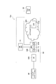
- FIG. 1 is an overall schematic configuration diagram of the remote control system 10.
- FIG. 2 is an overall schematic configuration diagram of the remote control system 10a.
- FIG. 3 is a diagram showing a protocol stack of gNB200.
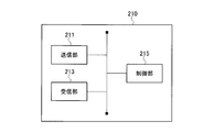
- FIG. 4 is a functional block configuration diagram of gNB-CU210.
- FIG. 5 is a functional block configuration diagram of gNB-DU230.
- FIG. 6 is a diagram showing a sequence of distribution processing 1 at a reference time in broadcast RRC signaling.
- FIG. 7 is a diagram showing a sequence of distribution processing 2 at a reference time in broadcast RRC signaling.
- FIG. 8 is a diagram showing a sequence of distribution processing 1 at a reference time in unicast RRC signaling.
- FIG. 9 is a diagram showing a sequence of delivery processing 2 at a reference time in unicast RRC signaling.
- FIG. 10 is a diagram showing a sequence of delivery processing 3 at a reference time in unicast RRC signaling.
- FIG. 11 is a diagram showing an example of the hardware configuration of gNB-CU210 and gNB-DU230.
- FIG. 1 is an overall schematic configuration diagram of the remote control system 10 according to the embodiment.
- the remote control system 10 includes a TSN grand master (TSNGM) 20, an NR system 30, and an end station 40.
- TSN control source (not shown) remotely controls the TSN end station 40 in real time via the NR system 30.
- the specific configuration of the remote control system 10 including the number of gNBs and UEs is not limited to the example shown in FIG.
- the TSN GM20 oscillates the clock for generating the TSN time with high accuracy.
- the time generated based on the clock oscillated by the TSN GM20 is referred to as the TSN time.
- the TSN time is the reference time applied within the TSN.
- the NR system 30 includes the NR grandmaster (NR GM) 31, UE100, gNB200, and core network 300.
- the NR GM31 oscillates the clock that is the operation timing of the NR system 30.
- the time generated based on the clock oscillated by the NR GM31 is referred to as the NR time.
- the NR time is the reference time applied within the NR system 30.
- the UE100 executes wireless communication according to NR between UE100 and gNB200 and core network 300.
- the UE100 receives at least one of the broadcast RRC signaling and the unicast RRC signaling including the NR time as the reference time from the gNB200.
- the UE100 synchronizes the time based on the received NR time in order to support TSN.
- the gNB200 executes wireless communication according to NR between the gNB200 and the core network 300.
- the gNB200 is composed of a Central Unit (gNB-CU) 210 and a Distributed Unit (gNB-DU) 230.
- the gNB-CU210 is located on the core network 300 side and controls the gNB-DU230.
- the gNB-CU210 may control a plurality of gNB-DU230s.
- gNB-DU230 is located on the UE100 side.
- the gNB-CU210 is connected to the gNB-DU230 via an F1 interface (for example, an optical fiber).
- the gNB-CU210 communicates with the UE 100 via the gNB-DU230.
- a hub, router, etc. can be installed between the gNB-CU210 and gNB-DU230.
- At least gNB-DU230 performs time synchronization based on the NR time. Note that only gNB-DU230 may perform time synchronization based on the NR time.
- the gNB 200 transmits at least one of the broadcast RRC signaling and the unicast RRC signaling including the NR time as the reference time to the UE 100.
- UE100 and gNB200 include Massive MIMO, which generates a more directional beam by controlling radio signals transmitted from multiple antenna elements, carrier aggregation (CA) using multiple component carriers (CC), and multiple carriers. It is possible to support dual connectivity (DC) in which component carriers are transmitted simultaneously between gNB and UE.
- Massive MIMO which generates a more directional beam by controlling radio signals transmitted from multiple antenna elements, carrier aggregation (CA) using multiple component carriers (CC), and multiple carriers.
- CA carrier aggregation
- CC component carriers
- DC dual connectivity
- the core network 300 communicates with the UE 100 via the gNB 200.
- the core network 300 has a User Plane Function (UPF) 310.
- UPF310 provides functions specialized for U-plane processing.
- the UPF310 is connected to TSN GM20.
- the TSN GM20 may be connected to the gNB 200 instead of the UPF310.
- the gNB 200 can transmit at least one of the broadcast RRC signaling and the unicast RRC signaling including the TSN time as the reference time to the UE 100.
- UE100 performs time synchronization based on the received TSN time in order to support TSN.
- At least gNB-DU230 synchronizes the time based on at least one reference time of NR time and TSN time. Note that only gNB-DU230 may perform time synchronization based on the reference time.
- the gNB 200 may transmit at least one of the broadcast RRC signaling and the unicast RRC signaling including the NR time and the TSN time as the reference time to the UE 100.
- the UE 100 may perform time synchronization based on at least one reference time of the received NR time and TSN time in order to correspond to the TSN.
- the end station 40 is a machine (for example, a robot arm) installed in the production factory.
- the end station 40 receives a command from the TSN control source via the NR system 30.
- the control source of the TSN performs real-time remote control in the remote control system 10 by performing time scheduling for operating the end station 40 based on the TSN time.
- FIG. 3 shows the protocol stack of gNB200.
- gNB200 includes gNB-CU210 and gNB-DU230.
- the gNB-CU210 provides an upper layer, specifically, a packet data convergence protocol layer (PDCP) and a radio resource control layer (RRC).
- PDCP packet data convergence protocol layer
- RRC radio resource control layer
- SDAP service data adaptation protocol layer
- the gNB-CU210 controls the operation of the gNB-DU230.
- the gNB-CU210 terminates the F1 interface with the gNB-DU230.
- the gNB-DU230 provides a lower layer, specifically, a physical layer (L1) and a radio unit (RF), a medium access control layer (MAC), and a radio link control layer (RLC).
- L1 physical layer
- RF radio unit
- MAC medium access control layer
- RLC radio link control layer
- the gNB-DU230 executes communication with the UE100 via the lower layer.
- the gNB-DU 230 constitutes a first communication device that executes wireless communication with the UE 100.
- GNB-DU230 supports one or more cells. One cell is supported by only one gNB-DU.
- the gNB-DU230 terminates the F1 interface with the gNB-CU210.
- gNB-CU210 is connected to gNB-DU230 and communicates with UE100 via RRC, which is higher than lower layers such as RLC.
- the gNB-CU 210 constitutes a second communication device that is connected to the gNB-DU230 and communicates with the UE 100 via the gNB-DU230.
- FIG. 4 is a functional block configuration diagram of gNB-CU210.
- the hardware configuration of gNB-CU210 will be described later.
- the gNB-CU210 includes a transmission unit 211, a reception unit 213, and a control unit 215.
- the transmitter 211 requests the gNB-DU230 to rewrite the coded system information, the coded RRC message, the request signal for requesting the information about the reference time from the gNB-DU230, and the TimeReferenceInforList. It sends a request signal, a message creation instruction to instruct the gNB-DU230 to create an RRC message, and predetermined information for the gNB-DU230 to communicate with the UE100.
- the receiving unit 213 receives the reference SFN, the reference time in the gNB-DU230 associated with the reference SFN, and the like from the gNB-DU230.
- Control unit 215 sets system information, sets RRC messages, encodes system information, encodes RRC messages, and so on.
- FIG. 5 is a functional block configuration diagram of gNB-DU230.
- the hardware configuration of gNB-DU230 will be described later.
- the gNB-DU230 includes a transmission unit 231, a reception unit 233, and a control unit 235.
- the transmission unit 231 transmits the reference SFN, the reference time in the gNB-DU230 associated with the reference SFN, and the like to the gNB-CU210.
- the transmitter 231 transmits the encoded system information, the encoded RRC message, and the like to the UE 100.
- the receiver 233 receives a coded system information, a coded RRC message from the gNB-CU210, a request signal for requesting information about the reference time from the gNB-DU230, and a request message for requesting rewriting of the TimeReferenceInforList. , Receives message creation instructions for instructing gNB-DU230 to create RRC messages, and predetermined information for gNB-DU230 to communicate with UE100.
- Control unit 235 updates (rewrites) system information, sets RRC messages, updates (rewrites) RRC messages, decodes system information, encodes system information, encodes RRC messages, and so on.
- Reference time distribution process 1 In the distribution process 1, the reference time is set for the timeInfoUTC in the system information (for example, System Information Block (SIB) 9) that notifies the time.
- SIB System Information Block
- FIG. 6 is a diagram showing a sequence of distribution processing 1 at a reference time.
- the gNB-CU210 sets the NR time at the timing of delivering the system information to the timeInfoUTC in the system information as the reference time.
- the reference time aaaa is set in the timeInfoUTC in SIB9.
- the gNB-CU210 encodes the system information and transmits it to the gNB-DU230 (S1).
- the gNB-DU230 When the gNB-DU230 receives the system information, it decodes the system information. gNB-DU230 updates the NR time set in timeInfoUTC in the system information to the NR time at the timing of delivering the system information (S2). In this embodiment, the reference time aaaa set in timeInfoUTC in SIB9 is updated to the reference time bbbb.
- the gNB-DU230 encodes the system information and notifies the system information including the updated reference time (S3).
- At least one of the NR time and the TSN time can be set in timeInfoUTC.
- TimeReferenceInfoList is set in the system information for notifying the time (for example, System Information Block (SIB) 9).
- SIB System Information Block
- the system frame number (reference SFN) assigned to the reference wireless frame is set for the referenceSFN in the information element TimeReferenceInfoList. Further, for Time in the information element TimeReferenceInfoList, the NR time in gNB-DU230 associated with the reference SFN set in referenceSFN is set as the reference time.
- the reference time set in Time is, for example, the NR time in the gNB-DU230 at the terminal boundary of the System Information window (SI window), which is the period for transmitting system information, or the SFN boundary immediately after the terminal boundary.
- SI window System Information window
- At least one of the NR time and the TSN time in the gNB-DU230 is set to the Time in the information element TimeReferenceInfoList. be able to.
- FIG. 7 is a diagram showing a sequence of the delivery process 2 at the reference time.
- the gNB-DU230 transmits the reference SFN and the reference time in the gNB-DU230 associated with the reference SFN to the gNB-CU210 based on the request from the gNB-CU210, the predetermined timing, etc. (S11).
- the reference SFN XXX is transmitted as the reference SFN
- the reference time aaaa is transmitted as the Time.
- the gNB-CU210 sets the reference SFN transmitted from the gNB-DU230 in the referenceSFN of the information element TimeReferenceInfoList in the system information, and sets the reference time transmitted from the gNB-DU230 in the Time of the information element TimeReferenceInfoList. (S13).
- the reference SFN XXX is set in the referenceSFN of the information element TimeReferenceInfoList in SIB9, and the reference time aaaa is set in the time of the information element TimeReferenceInfoList.
- the gNB-CU210 encodes the system information and transmits the system information including the reference SFN and the reference time transmitted from the gNB-DU230 to the gNB-DU230 (S15).
- the gNB-DU230 notifies the transmitted system information (S17).
- the gNB 200 may select either one of the above-mentioned distribution process 1 and the distribution process 2 according to the information element for setting the reference time. For example, when delivering the reference time to UE100 using timeInfoUTC in the system information, gNB200 selects delivery process 1. On the other hand, when the reference time is delivered to the UE 100 by using the information element TimeReferenceInfoList in the system information, the gNB 200 selects the delivery process 2.
- the information element TimeReferenceInfoList is set in the RRC message (for example, DLInformationTransfer message).
- the system frame number (reference SFN) assigned to the reference wireless frame is set for the referenceSFN in the information element TimeReferenceInfoList. Further, for Time in the information element TimeReferenceInfoList, the NR time in gNB-DU230 associated with the reference SFN set in referenceSFN is set as the reference time.
- the reference time set in Time corresponds to the NR time in gNB-DU230 at the end boundary of SFN set in the reference SFN.
- the TSN GM20 when the TSN GM20 is connected to the gNB 200, set the reference time of at least one of the NR time and the TSN time in the gNB-DU230 to Time in the information element TimeReferenceInfoList. Can be done.
- FIG. 8 is a diagram showing a sequence of distribution processing 1 at a reference time.
- the gNB-CU210 transmits a request signal to the gNB-DU230 in order to request information on the reference time from the gNB-DU230 (S21).
- the gNB-DU230 transmits the reference SFN and the reference time in the gNB-DU230 associated with the reference SFN to the gNB-CU210 in response to the reception of the request signal (S23).
- the reference SFN XXX is transmitted as the reference SFN
- the reference time aaaa is transmitted as the Time.
- the gNB-CU210 sets the reference SFN transmitted from the gNB-DU230 in the referenceSFN of the information element TimeReferenceInfoList in the RRC message addressed to the UE100, and sets the Time of the information element TimeReferenceInfoList to the reference time transmitted from the gNB-DU230. Is set (S25).
- the reference SFN XXX is set in the referenceSFN of the information element TimeReferenceInfoList in the DLInformationTransfer message, and the reference time aaaa is set in the time of the information element TimeReferenceInfoList.
- the gNB-CU210 encodes the RRC message and transmits the RRC message including the reference SFN and the reference time transmitted from the gNB-DU230 to the UE100 via the gNB-DU230 (S27).
- the UE100 When the UE100 receives the RRC message, it may notify the gNB-CU210 of an acknowledgment signal (ACK) via the gNB-DU230.
- ACK acknowledgment signal
- FIG. 9 is a diagram showing a sequence of the delivery process 2 at the reference time.
- the gNB-CU210 sends a message creation instruction to the gNB-DU230 in order to instruct the gNB-DU230 to compose an RRC message addressed to the UE100 (S31).
- the gNB-CU 210 notifies the predetermined information for the gNB-DU 230 to communicate with the UE 100 together with the message creation instruction.
- Predetermined information includes the following information elements: Transaction ID, Cyphering Algorithm, KEY (Security Key), BEAER (Bearer Identity-1), COUNT (HFN + PDCP SN), DIRECTION (0 for uplink and 1 for downlink). ), And LENGTH.
- the gNB-CU210 notifies the gNB-DU230 of all or part of the above-mentioned information elements as predetermined information. It is self-evident that DIRECTION is set to 1 because RRC messages are sent on the downlink. Therefore, the DIRECTION notification may be omitted.
- the length of the coded data is set in LENGTH. Since the gNB-DU230 can also identify the length of the encoded data, the LENGTH notification may be omitted.
- the Cyphering Algorithm and the KEY are information that is used to encode the RRC message and is uniquely determined between the UE 100 and the gNB-CU 210. Therefore, in order for the UE100 to succeed in decoding the RRC message, the gNB-DU230 uses the Cyphering Algorithm and KEY (Security Key) uniquely determined between the UE100 and the gNB-CU210 to obtain the RRC message. Need to be encoded. Therefore, the gNB-CU210 needs to notify the gNB-DU230 of at least the Cyphering Algorithm and the KEY (Security Key).
- the gNB-DU230 sets an RRC message addressed to UE100 in response to receiving a message creation instruction.
- gNB-DU230 sets the reference SFN in the referenceSFN of the information element TimeReferenceInfoList in the RRC message, and sets the reference time in the gNB-DU230 in the Time of the information element TimeReferenceInfoList (S33).
- the reference SFN XXX is set as the reference SFN
- the reference time aaaa is set as the Time.
- the gNB-DU230 encodes the RRC message based on the predetermined information and sends the RRC message including the reference SFN and the reference time to the UE100 (S35).
- the UE100 When the UE100 receives the RRC message, it may notify the gNB-CU210 of an acknowledgment signal (ACK) via the gNB-DU230.
- ACK acknowledgment signal
- FIG. 10 is a diagram showing a sequence of the delivery process 3 at the reference time.
- the gNB-CU210 notifies the gNB-DU230 of a request signal requesting rewriting of the TimeReferenceInfoList, a coded RRC message addressed to the UE100, and predetermined information for the gNB-DU230 to communicate with the UE100 (S41). ).
- the reference SFN of the information element TimeReferenceInfoList in the RRC message is set to the reference SFN, and the time of the information element TimeReferenceInfoList is set to the reference time in the gNB-CU210 associated with the reference SFN.
- the reference SFN XXX is set as the reference SFN
- the reference time aaaa is set as the Time.
- gNB-DU230 When gNB-DU230 receives an RRC message, it decodes the RRC message. gNB-DU230 updates the reference SFN set in the referenceSFN of the information element TimeReferenceInfoList in the RRC message, and also updates the reference time set in the Time of the information element TimeReferenceInfoList (S43). In the present embodiment, the reference SFN XXX set in the reference SFN is updated to YYY, and the reference time aaa set in Time is updated to bbbb.
- the gNB-DU230 encodes the RRC message based on the predetermined information and sends the RRC message including the updated reference SFN and the reference time to the UE100 (S45).
- the UE100 When the UE100 receives the RRC message, it may notify the gNB-CU210 of an acknowledgment signal (ACK) via the gNB-DU230.
- ACK acknowledgment signal
- the reference time may be delivered to UE100.
- the gNB 200 connects a gNB-DU230 that communicates with the UE100 and a gNB-CU210 that is connected to the gNB-DU230 and communicates with the UE100 via the gNB-DU230. Including.
- the gNB-CU210 is provided with a transmission unit 211 that transmits a request signal to the gNB-DU230.
- the gNB-DU230 sets the reference SFN and the reference time of at least one of the NR time and the TSN time associated with the reference SFN based on the reception unit 233 that receives the request signal and the received request signal. -Equipped with a transmitter 231 to transmit to the CU210.
- the transmission unit 211 of the gNB-CU210 transmits an RRC message including the reference SFN and the reference time to the UE 100 via the gNB-DU230.
- gNB200 can deliver an accurate reference time to UE100.
- the gNB-CU210 sends an RRC message as before, so changes to the conventional gNB-CU210 configuration can be minimized. Furthermore, it is no longer necessary to set the reference SFN and information other than the reference time associated with the reference SFN in the gNB-DU230.
- the gNB 200 includes a gNB-DU230 that communicates with the UE100 and a gNB-CU210 that is connected to the gNB-DU230 and communicates with the UE100 via the gNB-DU230.
- the gNB-CU210 is provided with a transmission unit 211 that transmits predetermined information for communicating with the UE100 to the gNB-DU230.
- the gNB-DU230 includes a receiving unit 233 that receives predetermined information, a reference SFN, and a control unit 235 that sets an RRC message including at least one of the NR time and TSN time associated with the reference SFN. , A transmission unit 231 that transmits a set RRC message to the UE 100 based on the received predetermined information.
- gNB200 can deliver an accurate reference time to UE100.
- the gNB 200 includes a gNB-DU230 that communicates with the UE100 and a gNB-CU210 that is connected to the gNB-DU230 and communicates with the UE100 via the gNB-DU230.
- the gNB-CU210 contains an RRC message including predetermined information for communicating with the UE 100, a reference SFN, and at least one reference time of the NR time and the TSN time associated with the reference SFN, gNB-DU230. It is provided with a transmission unit 211 for transmitting to.
- the gNB-DU230 is updated based on the receiving unit 233 that receives the predetermined information and the RRC message, the control unit 235 that updates the reference SFN and the reference time included in the received RRC message, and the received predetermined information. It includes a transmitter 231 that transmits an RRC message including a reference SFN and a reference time to the UE 100.
- gNB200 can deliver an accurate reference time to UE100.
- only gNB-DU230 performs time synchronization based on at least one reference time of NR time and TSN time.
- the gNB200 can deliver a more accurate reference time to the UE100.
- each functional block may be realized by using one device that is physically or logically connected, or directly or indirectly (for example, by using two or more physically or logically separated devices). , Wired, wireless, etc.) and may be realized using these plurality of devices.
- the functional block may be realized by combining the software with the one device or the plurality of devices.
- Functions include judgment, decision, judgment, calculation, calculation, processing, derivation, investigation, search, confirmation, reception, transmission, output, access, solution, selection, selection, establishment, comparison, assumption, expectation, deemed, and notification (There are, but are not limited to, broadcasting, notifying, communicating, forwarding, configuring, reconfiguring, allocating, mapping, assigning, etc. ..
- a functional block that makes transmission function is called a transmitting unit or a transmitter.
- the method of realizing each is not particularly limited.
- FIG. 11 is a diagram showing an example of the hardware configuration of the device. As shown in FIG. 11, the device may be configured as a computer device including a processor 1001, a memory 1002, a storage 1003, a communication device 1004, an input device 1005, an output device 1006, a bus 1007, and the like.
- the word “device” can be read as a circuit, device, unit, etc.
- the hardware configuration of the device may be configured to include one or more of each of the devices shown in the figure, or may be configured not to include some of the devices.
- Each functional block of the device is realized by any hardware element of the computer device or a combination of the hardware elements.
- the processor 1001 performs the calculation, controls the communication by the communication device 1004, and the memory. It is realized by controlling at least one of reading and writing of data in 1002 and storage 1003.
- Processor 1001 operates, for example, an operating system to control the entire computer.
- the processor 1001 may be composed of a central processing unit (CPU) including an interface with peripheral devices, a control device, an arithmetic unit, registers, and the like.
- CPU central processing unit
- the processor 1001 reads a program (program code), a software module, data, etc. from at least one of the storage 1003 and the communication device 1004 into the memory 1002, and executes various processes according to these.
- a program program code
- a program that causes a computer to execute at least a part of the operations described in the above-described embodiment is used.
- the various processes described above may be executed by one processor 1001 or may be executed simultaneously or sequentially by two or more processors 1001.
- Processor 1001 may be implemented by one or more chips.
- the program may be transmitted from the network via a telecommunication line.
- the memory 1002 is a computer-readable recording medium, and is composed of at least one of, for example, ReadOnlyMemory (ROM), ErasableProgrammableROM (EPROM), Electrically ErasableProgrammableROM (EEPROM), RandomAccessMemory (RAM), and the like. May be done.
- the memory 1002 may be called a register, a cache, a main memory (main storage device), or the like.
- the memory 1002 can store a program (program code), a software module, or the like that can execute the method according to the embodiment of the present disclosure.
- the storage 1003 is a computer-readable recording medium, for example, an optical disk such as a Compact Disc ROM (CD-ROM), a hard disk drive, a flexible disk, a photomagnetic disk (for example, a compact disk, a digital versatile disk, a Blu-ray). It may consist of at least one (registered trademark) disk), smart card, flash memory (eg, card, stick, key drive), floppy (registered trademark) disk, magnetic strip, and the like.
- Storage 1003 may be referred to as auxiliary storage.
- the recording medium described above may be, for example, a database, server or other suitable medium containing at least one of memory 1002 and storage 1003.
- the communication device 1004 is hardware (transmission / reception device) for communicating between computers via at least one of a wired network and a wireless network, and is also referred to as, for example, a network device, a network controller, a network card, a communication module, or the like.
- Communication device 1004 includes, for example, a high frequency switch, a duplexer, a filter, a frequency synthesizer, etc. in order to realize at least one of frequency division duplex (FDD) and time division duplex (TDD). It may be composed of.
- FDD frequency division duplex
- TDD time division duplex
- the input device 1005 is an input device (for example, keyboard, mouse, microphone, switch, button, sensor, etc.) that accepts input from the outside.
- the output device 1006 is an output device (for example, a display, a speaker, an LED lamp, etc.) that outputs to the outside.
- the input device 1005 and the output device 1006 may have an integrated configuration (for example, a touch panel).
- each device such as the processor 1001 and the memory 1002 is connected by the bus 1007 for communicating information.
- the bus 1007 may be configured by using a single bus, or may be configured by using a different bus for each device.
- the device includes hardware such as a microprocessor, a digital signal processor (Digital Signal Processor: DSP), an Application Specific Integrated Circuit (ASIC), a Programmable Logic Device (PLD), and a Field Programmable Gate Array (FPGA).
- the hardware may implement some or all of each functional block.
- processor 1001 may be implemented using at least one of these hardware.
- information notification includes physical layer signaling (for example, Downlink Control Information (DCI), Uplink Control Information (UCI), upper layer signaling (eg, RRC signaling, Medium Access Control (MAC) signaling, broadcast information (Master Information Block)). (MIB), System Information Block (SIB)), other signals or combinations thereof.
- DCI Downlink Control Information
- UCI Uplink Control Information
- RRC signaling may also be referred to as an RRC message, for example, RRC Connection Setup. ) Message, RRC Connection Reconfiguration message, etc. may be used.
- LTE LongTermEvolution
- LTE-A LTE-Advanced
- SUPER3G IMT-Advanced
- 4G 4th generation mobile communication system
- 5G 5th generation mobile communication system
- FutureRadioAccess FAA
- NewRadio NR
- W-CDMA registered trademark
- GSM registered trademark
- CDMA2000 Code Division Multiple Access 2000
- UMB UltraMobile Broadband
- IEEE802.11 Wi-Fi (registered trademark)
- IEEE802.16 WiMAX®
- IEEE802.20 Ultra-WideBand (UWB), Bluetooth®, and other systems that utilize appropriate systems and at least one of the next generation systems extended based on them.
- a plurality of systems may be applied in combination (for example, a combination of at least one of LTE and LTE-A and 5G).
- the specific operation performed by the base station in the present disclosure may be performed by its upper node (upper node).
- various operations performed for communication with a terminal are performed by the base station and other network nodes other than the base station (for example, MME or). It is clear that it can be done by at least one of (but not limited to, S-GW, etc.).
- S-GW network node
- the case where there is one network node other than the base station is illustrated above, it may be a combination of a plurality of other network nodes (for example, MME and S-GW).
- Information and signals can be output from the upper layer (or lower layer) to the lower layer (or upper layer).
- Input / output may be performed via a plurality of network nodes.
- the input / output information may be stored in a specific location (for example, memory) or may be managed using a management table.
- the input / output information can be overwritten, updated, or added.
- the output information may be deleted.
- the input information may be transmitted to another device.
- the determination may be made by a value represented by 1 bit (0 or 1), by a boolean value (Boolean: true or false), or by comparing numerical values (for example, a predetermined value). It may be done by comparison with the value).
- the notification of predetermined information (for example, the notification of "being X") is not limited to the explicit one, but is performed implicitly (for example, the notification of the predetermined information is not performed). May be good.
- Software is an instruction, instruction set, code, code segment, program code, program, subprogram, software module, whether called software, firmware, middleware, microcode, hardware description language, or another name.
- Applications, software applications, software packages, routines, subroutines, objects, executable files, execution threads, procedures, functions, etc. should be broadly interpreted to mean.
- software, instructions, information, etc. may be transmitted and received via a transmission medium.
- a transmission medium For example, a website, where the software uses at least one of wired technology (coaxial cable, fiber optic cable, twist pair, Digital Subscriber Line (DSL), etc.) and wireless technology (infrared, microwave, etc.).
- wired technology coaxial cable, fiber optic cable, twist pair, Digital Subscriber Line (DSL), etc.
- wireless technology infrared, microwave, etc.
- the information, signals, etc. described in this disclosure may be represented using any of a variety of different techniques.
- data, instructions, commands, information, signals, bits, symbols, chips, etc. that may be referred to throughout the above description are voltages, currents, electromagnetic waves, magnetic fields or magnetic particles, light fields or photons, or any of these. It may be represented by a combination of.
- a channel and a symbol may be a signal (signaling).
- the signal may be a message.
- the component carrier (CC) may be referred to as a carrier frequency, a cell, a frequency carrier, or the like.
- system and “network” used in this disclosure are used interchangeably.
- the information, parameters, etc. described in the present disclosure may be expressed using absolute values, relative values from predetermined values, or using other corresponding information. It may be represented.
- the radio resource may be one indicated by an index.
- Base Station BS
- Wireless Base Station Wireless Base Station
- NodeB NodeB
- eNodeB eNodeB
- gNodeB gNodeB
- Base stations are sometimes referred to by terms such as macrocells, small cells, femtocells, and picocells.
- the base station can accommodate one or more (for example, three) cells (also called sectors). When a base station accommodates multiple cells, the entire coverage area of the base station can be divided into multiple smaller areas, each smaller area being a base station subsystem (eg, a small indoor base station (Remote Radio)). Communication services can also be provided by Head: RRH).
- a base station subsystem eg, a small indoor base station (Remote Radio)
- Communication services can also be provided by Head: RRH).
- cell refers to a base station that provides communication services in this coverage, and part or all of the coverage area of at least one of the base station subsystems.
- MS mobile station
- UE user equipment
- terminal terminal
- Mobile stations can be subscriber stations, mobile units, subscriber units, wireless units, remote units, mobile devices, wireless devices, wireless communication devices, remote devices, mobile subscriber stations, access terminals, mobile terminals, wireless, depending on the trader. It may also be referred to as a terminal, remote terminal, handset, user agent, mobile client, client, or some other suitable term.
- At least one of the base station and the mobile station may be called a transmitting device, a receiving device, a communication device, or the like.
- At least one of the base station and the mobile station may be a device mounted on the mobile body, the mobile body itself, or the like.
- the moving body may be a vehicle (eg, car, airplane, etc.), an unmanned moving body (eg, drone, self-driving car, etc.), or a robot (manned or unmanned). ) May be.
- at least one of the base station and the mobile station includes a device that does not necessarily move during communication operation.
- at least one of a base station and a mobile station may be an Internet of Things (IoT) device such as a sensor.
- IoT Internet of Things
- the base station in the present disclosure may be read as a mobile station (user terminal, the same applies hereinafter).
- communication between a base station and a mobile station has been replaced with communication between a plurality of mobile stations (for example, it may be called Device-to-Device (D2D), Vehicle-to-Everything (V2X), etc.).
- D2D Device-to-Device
- V2X Vehicle-to-Everything
- Each aspect / embodiment of the present disclosure may be applied to the configuration.
- the mobile station may have the function of the base station.
- words such as "up” and “down” may be read as words corresponding to inter-terminal communication (for example, "side").
- the uplink, downlink, and the like may be read as side channels.
- the mobile station in the present disclosure may be read as a base station.
- the base station may have the functions of the mobile station.
- connection means any direct or indirect connection or connection between two or more elements, and each other. It can include the presence of one or more intermediate elements between two “connected” or “combined” elements.
- the connection or connection between the elements may be physical, logical, or a combination thereof.
- connection may be read as "access”.
- the two elements use at least one of one or more wires, cables and printed electrical connections, and, as some non-limiting and non-comprehensive examples, the radio frequency domain.
- Electromagnetic energies with wavelengths in the microwave and light (both visible and invisible) regions, etc. can be considered to be “connected” or “coupled” to each other.
- the reference signal can also be abbreviated as Reference Signal (RS), and may be called a pilot (Pilot) depending on the applicable standard.
- RS Reference Signal
- Pilot pilot
- references to elements using designations such as “first”, “second” as used in this disclosure does not generally limit the quantity or order of those elements. These designations can be used in the present disclosure as a convenient way to distinguish between two or more elements. Thus, references to the first and second elements do not mean that only two elements can be adopted there, or that the first element must somehow precede the second element.
- the term "A and B are different” may mean “A and B are different from each other”.
- the term may mean that "A and B are different from C”.
- Terms such as “separate” and “combined” may be interpreted in the same way as “different”.
- radio base station According to the radio base station described above, it is useful in HLS because it can deliver an accurate reference time to the user device.
Abstract
La présente invention concerne une gNB (200) comprenant une gNB-DU (230) communiquant avec un UE (100), et une gNB-CU (210) connectée à la gNB-DU (230) et communiquant avec l'UE (100) par l'intermédiaire de la gNB-DU (230). La gNB-CU (210) est pourvue d'une unité de transmission (211) pour transmettre un signal de demande à la gNB-DU (230). La gNB-DU (230) est pourvue d'une unité de réception (233) pour recevoir le signal de demande, et d'une unité de transmission (231) pour transmettre un numéro de trame de système de référence et un temps de référence du jour dans un réseau prescrit qui est associé au numéro de trame de système de référence à la gNB-CU (210) sur la base du signal de demande reçu. L'unité de transmission (211) de la gNB-CU (210) transmet un message de commande de ressource sans fil (RRC) qui comprend le numéro de trame de système de référence et le temps de référence du jour à l'UE (100) par l'intermédiaire de la gNB-DU (230).
Priority Applications (5)
| Application Number | Priority Date | Filing Date | Title |
|---|---|---|---|
| PCT/JP2019/018056 WO2020217488A1 (fr) | 2019-04-26 | 2019-04-26 | Station de base sans fil |
| CN201980095521.0A CN113711654A (zh) | 2019-04-26 | 2019-04-26 | 无线基站 |
| EP19926591.9A EP3962187A4 (fr) | 2019-04-26 | 2019-04-26 | Station de base sans fil |
| JP2021515718A JPWO2020217488A1 (fr) | 2019-04-26 | 2019-04-26 | |
| US17/605,959 US20220200733A1 (en) | 2019-04-26 | 2019-04-26 | Radio base station |
Applications Claiming Priority (1)
| Application Number | Priority Date | Filing Date | Title |
|---|---|---|---|
| PCT/JP2019/018056 WO2020217488A1 (fr) | 2019-04-26 | 2019-04-26 | Station de base sans fil |
Publications (1)
| Publication Number | Publication Date |
|---|---|
| WO2020217488A1 true WO2020217488A1 (fr) | 2020-10-29 |
Family
ID=72940895
Family Applications (1)
| Application Number | Title | Priority Date | Filing Date |
|---|---|---|---|
| PCT/JP2019/018056 WO2020217488A1 (fr) | 2019-04-26 | 2019-04-26 | Station de base sans fil |
Country Status (5)
| Country | Link |
|---|---|
| US (1) | US20220200733A1 (fr) |
| EP (1) | EP3962187A4 (fr) |
| JP (1) | JPWO2020217488A1 (fr) |
| CN (1) | CN113711654A (fr) |
| WO (1) | WO2020217488A1 (fr) |
Families Citing this family (2)
| Publication number | Priority date | Publication date | Assignee | Title |
|---|---|---|---|---|
| CN111417186B (zh) * | 2019-01-07 | 2021-07-16 | 华为技术有限公司 | 一种时间同步方法和装置 |
| EP3815428A1 (fr) * | 2019-08-14 | 2021-05-05 | Nokia Solutions and Networks Oy | Améliorations de distribution d'informations de système |
Family Cites Families (10)
| Publication number | Priority date | Publication date | Assignee | Title |
|---|---|---|---|---|
| US8934452B2 (en) * | 2012-07-17 | 2015-01-13 | Alcatel Lucent | Method, apparatus and computer readable medium for timing alignment in overlaid heterogeneous wireless networks |
| CN104704903A (zh) * | 2012-11-09 | 2015-06-10 | 富士通株式会社 | 信息配置方法、信息发送方法、检测方法及其装置、系统 |
| EP2984900B1 (fr) * | 2013-04-12 | 2017-03-08 | Telefonaktiebolaget LM Ericsson (publ) | Synchronisation de numéros de trame système |
| JP2019176196A (ja) * | 2016-08-10 | 2019-10-10 | 株式会社Nttドコモ | 基地局、ユーザ装置及び信号送信方法 |
| CN108809595B (zh) * | 2017-05-05 | 2024-02-09 | 华为技术有限公司 | 一种参考信号通知方法及其装置 |
| JP2019029716A (ja) * | 2017-07-26 | 2019-02-21 | 株式会社Nttドコモ | 無線基地局、タイミング制御方法、およびユーザ端末 |
| CN109412770B (zh) * | 2017-09-23 | 2019-09-20 | 华为技术有限公司 | 通信方法及装置 |
| US10855814B2 (en) * | 2017-10-20 | 2020-12-01 | Comcast Cable Communications, Llc | Non-access stratum capability information |
| CN111417186B (zh) * | 2019-01-07 | 2021-07-16 | 华为技术有限公司 | 一种时间同步方法和装置 |
| US20200259896A1 (en) * | 2019-02-13 | 2020-08-13 | Telefonaktiebolaget Lm Ericsson (Publ) | Industrial Automation with 5G and Beyond |
-
2019
- 2019-04-26 EP EP19926591.9A patent/EP3962187A4/fr active Pending
- 2019-04-26 WO PCT/JP2019/018056 patent/WO2020217488A1/fr unknown
- 2019-04-26 CN CN201980095521.0A patent/CN113711654A/zh active Pending
- 2019-04-26 JP JP2021515718A patent/JPWO2020217488A1/ja active Pending
- 2019-04-26 US US17/605,959 patent/US20220200733A1/en active Pending
Non-Patent Citations (4)
| Title |
|---|
| 3GPP: "Generation Partnership Project; Technical Specification Group Services and System Aspects; Study on enhancement of 5GS for Vertical and LAN Services (Release 16", 3GPP TR 23.734, December 2018 (2018-12-01) |
| HUAWEI: "Reference timing delivery over F1", 3GPP DRAFT; R3-191917, vol. RAN WG3, 30 March 2019 (2019-03-30), Xi’an, China, pages 1 - 2, XP051695367 * |
| NTT DOCOMO; INC: "Time reference information delivery", 3GPP DRAFT; R3-192509 TIME REFERENCE INFORMATION DELIVERY R0, 3 May 2019 (2019-05-03), Reno, NV, USA, pages 1 - 8, XP051712719 * |
| SAMSUNG: "Generating and delivering the time reference information in split NG-RAN architecture", 3GPP DRAFT; R3-191534_DISC_PCR FOR TIME REFERENCE INFORMATION, vol. RAN WG3, 29 March 2019 (2019-03-29), Xi’an, China, pages 1 - 4, XP051694988 * |
Also Published As
| Publication number | Publication date |
|---|---|
| CN113711654A (zh) | 2021-11-26 |
| EP3962187A1 (fr) | 2022-03-02 |
| JPWO2020217488A1 (fr) | 2020-10-29 |
| EP3962187A4 (fr) | 2022-12-07 |
| US20220200733A1 (en) | 2022-06-23 |
Similar Documents
| Publication | Publication Date | Title |
|---|---|---|
| WO2020217538A1 (fr) | Nœud de communication sans fil | |
| WO2020217534A1 (fr) | Nœud de communication sans fil | |
| WO2020217488A1 (fr) | Station de base sans fil | |
| WO2020031310A1 (fr) | Système d'accès sans fil et dispositif de communication | |
| WO2020059149A1 (fr) | Nœud de réseau | |
| CN113273252B (zh) | 网络节点及用户装置 | |
| WO2020222271A1 (fr) | Dispositif d'utilisateur et procédé de communication | |
| WO2020202484A1 (fr) | Dispositif de communication et procédé de communication | |
| WO2020217492A1 (fr) | Station de base sans fil | |
| US20220124708A1 (en) | Radio base station and user equipment | |
| WO2020261461A1 (fr) | Terminal | |
| WO2020165979A1 (fr) | Station de base radio et équipement utilisateur | |
| WO2021029075A1 (fr) | Terminal et procédé de communication | |
| WO2020217480A1 (fr) | Équipement utilisateur et station de base sans fil | |
| JP7438225B2 (ja) | 交換機及び通信方法 | |
| RU2786013C1 (ru) | Базовая радиостанция | |
| WO2020165957A1 (fr) | Dispositif de communication | |
| WO2021019701A1 (fr) | Terminal et nœud de communication | |
| WO2020084745A1 (fr) | Équipement utilisateur | |
| WO2021070388A1 (fr) | Terminal | |
| WO2020222270A1 (fr) | Équipement d'utilisateur et procédé de communication | |
| WO2021028998A1 (fr) | Nœud de communication sans fil | |
| WO2020031326A1 (fr) | Système de communication et procédé de commande de communication | |
| WO2020217540A1 (fr) | Nœud de communication sans fil | |
| JP2020170996A (ja) | ネットワーク制御装置及び通信方法 |
Legal Events
| Date | Code | Title | Description |
|---|---|---|---|
| 121 | Ep: the epo has been informed by wipo that ep was designated in this application |
Ref document number: 19926591 Country of ref document: EP Kind code of ref document: A1 |
|
| ENP | Entry into the national phase |
Ref document number: 2021515718 Country of ref document: JP Kind code of ref document: A |
|
| NENP | Non-entry into the national phase |
Ref country code: DE |
|
| ENP | Entry into the national phase |
Ref document number: 2019926591 Country of ref document: EP Effective date: 20211126 |