WO2020213309A1 - 車載レーダー装置用レドーム及びその製造方法 - Google Patents
車載レーダー装置用レドーム及びその製造方法 Download PDFInfo
- Publication number
- WO2020213309A1 WO2020213309A1 PCT/JP2020/010599 JP2020010599W WO2020213309A1 WO 2020213309 A1 WO2020213309 A1 WO 2020213309A1 JP 2020010599 W JP2020010599 W JP 2020010599W WO 2020213309 A1 WO2020213309 A1 WO 2020213309A1
- Authority
- WO
- WIPO (PCT)
- Prior art keywords
- surface side
- heater
- layer
- recess
- base material
- Prior art date
- Legal status (The legal status is an assumption and is not a legal conclusion. Google has not performed a legal analysis and makes no representation as to the accuracy of the status listed.)
- Ceased
Links
Images


Classifications
-
- B—PERFORMING OPERATIONS; TRANSPORTING
- B60—VEHICLES IN GENERAL
- B60R—VEHICLES, VEHICLE FITTINGS, OR VEHICLE PARTS, NOT OTHERWISE PROVIDED FOR
- B60R13/00—Elements for body-finishing, identifying, or decorating; Arrangements or adaptations for advertising purposes
-
- G—PHYSICS
- G01—MEASURING; TESTING
- G01S—RADIO DIRECTION-FINDING; RADIO NAVIGATION; DETERMINING DISTANCE OR VELOCITY BY USE OF RADIO WAVES; LOCATING OR PRESENCE-DETECTING BY USE OF THE REFLECTION OR RERADIATION OF RADIO WAVES; ANALOGOUS ARRANGEMENTS USING OTHER WAVES
- G01S13/00—Systems using the reflection or reradiation of radio waves, e.g. radar systems; Analogous systems using reflection or reradiation of waves whose nature or wavelength is irrelevant or unspecified
- G01S13/88—Radar or analogous systems specially adapted for specific applications
- G01S13/93—Radar or analogous systems specially adapted for specific applications for anti-collision purposes
- G01S13/931—Radar or analogous systems specially adapted for specific applications for anti-collision purposes of land vehicles
-
- G—PHYSICS
- G01—MEASURING; TESTING
- G01S—RADIO DIRECTION-FINDING; RADIO NAVIGATION; DETERMINING DISTANCE OR VELOCITY BY USE OF RADIO WAVES; LOCATING OR PRESENCE-DETECTING BY USE OF THE REFLECTION OR RERADIATION OF RADIO WAVES; ANALOGOUS ARRANGEMENTS USING OTHER WAVES
- G01S7/00—Details of systems according to groups G01S13/00, G01S15/00, G01S17/00
- G01S7/02—Details of systems according to groups G01S13/00, G01S15/00, G01S17/00 of systems according to group G01S13/00
- G01S7/03—Details of HF subsystems specially adapted therefor, e.g. common to transmitter and receiver
-
- H—ELECTRICITY
- H01—ELECTRIC ELEMENTS
- H01Q—ANTENNAS, i.e. RADIO AERIALS
- H01Q1/00—Details of, or arrangements associated with, antennas
- H01Q1/42—Housings not intimately mechanically associated with radiating elements, e.g. radome
Definitions
- the present invention relates to a radome for an in-vehicle radar device provided on the front side of the in-vehicle radar device, and particularly relates to a radome for an in-vehicle radar device having a snow melting function and a method for manufacturing the radome.
- a radome for an in-vehicle radar device a radome that exhibits a snow melting function while ensuring the necessary electromagnetic wave transmission is known.
- a radome there is a radome of Patent Document 1 in which a heater layer is provided on the rear side of the decorative layer to ensure good visibility of the decorative layer.
- the redome of Patent Document 1 has a transparent substrate and a first base material and a second base material arranged behind the transparent substrate, and a decorative layer is formed between the transparent substrate and the first base material.
- the first base material and the second base material are joined to each other by sandwiching the heater layer from the front and back and sealing them, and the transparent substrate, the decorative layer, the first base material, the heater layer, etc. It has a structure in which a second base material is provided.
- Patent Document 1 also discloses a structure in which a transparent substrate, a decorative layer, a void portion, a heater layer, and a base material are provided in order from the surface side as a conventional radome. It has been pointed out that the electromagnetic wave transmission performance of this conventional radome is lowered due to the relative permittivity of air in the voids, which is significantly different from the relative permittivity of the transparent substrate and the base material (Patent Document 1 paragraph [0004]. , [0010], see FIG. 10 (b)).
- the radome of Patent Document 1 suppresses a decrease in electromagnetic wave transmission performance by a structure in which a first base material of the same resin material as the second base material is arranged in a portion corresponding to a gap portion of the radome of the above-mentioned conventional example.
- the redome of Patent Document 1 has a structure in which the transparent substrate, the decorative layer, and the first base material are arranged between the surface of the transparent substrate and the heater layer, from the heater layer to the surface of the transparent substrate to which snow adheres. There is a problem that the distance between the two is increased and the heat conduction efficiency is lowered.
- the present invention has been proposed in view of the above problems, and it is possible to ensure good visibility of the decorative layer constituting the design portion of the emblem, improve electromagnetic wave transmission, and achieve a radome with high heat conduction efficiency. It is an object of the present invention to provide a radome for an in-vehicle radar device capable of reliably melting snow adhering to the outer surface of the radome and a method for manufacturing the radome.
- a transparent and electromagnetic wave transmitting front base material, a decorative layer, and a heater layer are provided in close contact with each other in order from the front surface side, and the first first base material on the back surface side of the front base material.
- the decorative layer is formed so as to partially project to the surface side so as to imitate the concave portion, and to the surface side so as to imitate the second concave portion on the back surface side of the decorative layer provided at a position corresponding to the first concave portion. It is characterized in that the heater layer is provided so as to partially project.
- the decorative layer on the surface side of the heater layer, it is possible to ensure good visibility of the decorative layer constituting the design portion of the emblem or the like through the transparent front base material. it can. Further, since the decorative layer and the heater layer are provided in close contact with each other without providing a gap or a base material between the decorative layer and the heater layer, electromagnetic wave transmission can be improved. Further, since the front base material and the decorative layer are provided between the surface of the transparent front base material and the heater layer without providing another base material, the heater layer can be transferred to the surface of the front base material. The heat conduction efficiency can be increased, and the snow and ice adhering to the outer surface of the radome can be reliably melted.
- the heater layer partially protrudes toward the surface side, so that the heater layer or its heater does not increase the occupied area per unit area of the surface of the front base material. It is possible to increase the density of elements. As a result, it is possible to further improve the electromagnetic wave transmission while surely melting the snow.
- the front base material is installed between the surface of the front base material and the heater layer, the heating of the heater layer is thermally diffused by the thickness and spread of the front base material, and the entire surface of the front base material is obtained. It is possible to melt snow with high uniformity.
- the base material is not provided between the decorative layer and the heater layer, the molding process of the base material during this period can be eliminated, and the production can be performed with higher production efficiency.
- the radome for an in-vehicle radar device of the present invention is provided on the back side of the heater layer so as to engage a convex portion with a third recess on the back side of the heater layer provided at a position corresponding to the second recess. It is characterized in that a base material is provided after the electromagnetic wave transmission. According to this, the convex portion of the rear base material and the heater layer are provided by engaging the convex portion of the rear base material with the third concave portion on the back surface side of the heater layer to provide the rear base material on the back surface side of the heater layer.
- the third recess of the above can be engaged and fixed to be fixed with higher strength.
- the radome for an in-vehicle radar device of the present invention is characterized in that the directions of currents flowing through adjacently wired heater elements in the heater layer are substantially antiparallel to each other. According to this, by making the directions of the currents flowing through the adjacent heater elements substantially antiparallel to each other, the electromagnetic waves radiated from the adjacent heater elements are in opposite phase, and the electromagnetic radiation from the heater elements is canceled. It is possible to obtain better electromagnetic wave transmission performance. In particular, by making the directions of the currents flowing through the heater elements wired adjacent to each other substantially antiparallel to each other, it is possible to exhibit extremely excellent electromagnetic wave transmission performance as a whole.
- the radome for an in-vehicle radar device of the present invention is characterized in that the heater layer is composed of an insulating film and a heater element fixed to the back surface side of the insulating film. According to this, by guaranteeing the insulation property by the insulating film, it is possible to prevent the decorative layer from being conductive by energizing the heater element regardless of the configuration of the decorative layer, and the conduction of the decorative layer is electromagnetic wave transmission. Can be reliably prevented from decreasing. Further, by fixing the heater element to the insulating film, the position of the heater element can be prevented from being displaced, and the heater element can be protected by the insulating film. Further, the insulating film functions as a base for fixing the heater element, and can increase the fixing strength of the heater element to the decorative layer.
- the radome for an in-vehicle radar device of the present invention is characterized in that the heater layer is composed of only a heater element. According to this, the heater element can be brought into close contact with the decorative layer directly, the heat conduction efficiency from the heater layer to the surface of the front base material can be further increased, and the snow adhering to the outer surface of the radome is more reliably melted. be able to.
- the distance from the surface of the front base material to the bottom located on the surface side of the first recess is set to 0.1 to 10 mm, and the heater layer partially protrudes.
- the distance from the tip of the portion to the innermost back surface of the heater layer other than the protruding portion is set to 1 to 10 mm.
- the method for manufacturing a radome for an in-vehicle radar device of the present invention is a method for manufacturing a radome for an in-vehicle radar device of the present invention, which follows the first recess on the back side of the electromagnetic wave transmitting front base material and forms a surface side.
- a heater layer composed of an insulating film and a heater element fixed to the back surface side of the insulating film is fixed to the decorative layer by engaging a protruding portion formed in a shape that imitates the second recess.
- the front base material on which the decorative layer is formed and the heater layer is provided is arranged in a mold, and the heater layer is provided at a position corresponding to the second recess. It is characterized by comprising a third step of forming an electromagnetic wave transmitting rear substrate by injection molding on the back surface side of the heater layer so as to engage a convex portion with the third concave portion on the back surface side. According to this, a protruding portion that partially protrudes on the surface side of the heater layer and has a shape that imitates the second recess is formed, and the heater layer composed of the insulating film and the heater element fixed to the back side thereof is used to project.
- the insulating film of the heater layer and the heater element can be easily aligned, and the manufacturing work can be facilitated. Further, since the heater layer of the intermediate product can be obtained by forming the heater element based only on the insulating film, it can be formed by using various manufacturing means, and the applicable manufacturing means are diversified. Can be planned. Further, by engaging the convex portion of the rear base material with the third concave portion on the back surface side of the heater layer and injection molding the rear base material on the back surface side of the heater layer, the convex portion of the rear base material and the heater layer are formed. After the high fixing strength in which the third recess is engaged and fixed, the base material can be provided on the back surface side.
- the method for manufacturing a radome for an in-vehicle radar device of the present invention is a method for manufacturing a radome for an in-vehicle radar device of the present invention.
- a third step of forming a heater layer composed of the insulating film and a heater element fixed to the back surface side of the insulating film, and the front base on which the decorative layer is formed and the heater layer is provided.
- the material is arranged in the mold, and the convex portion is engaged with the third concave portion on the back surface side of the heater layer provided at a position corresponding to the second concave portion so as to engage the convex portion on the back surface side of the heater layer. It is characterized by comprising a fourth step of forming a base material after electromagnetic wave transmission by injection molding.
- the protruding portion is engaged with the second recess to fix the insulating film.
- the insulating film can be easily aligned and provided, and the manufacturing work can be facilitated.
- the heater element can be stably installed at a more accurate position.
- the convex portion of the rear base material is engaged with the third concave portion on the back surface side of the heater layer and injection molding the rear base material on the back surface side of the heater layer. After the high fixing strength in which the third recess is engaged and fixed, the base material can be provided on the back surface side.
- the method for manufacturing a radome for an in-vehicle radar device of the present invention is a method for manufacturing a radome for an in-vehicle radar device of the present invention, in which the surface side follows the first recess on the back side of the electromagnetic wave transmitting front base material.
- the front base material on which the layer is formed and the heater layer is provided is arranged in a mold, and is provided with a third recess on the back surface side of the heater layer provided at a position corresponding to the second recess.
- the electromagnetic wave transmitting rear base material is injected onto the back surface side of the heater layer so as to engage the convex portion with the second concave portion provided with no or only a part of the heater element. It is characterized by including a third step of forming by molding. According to this, by forming the heater element directly on the back surface of the decorative layer, the heater element can be stably installed at a more accurate position on the back surface of the decorative layer.
- the convex portion of the rear base material is engaged with the third concave portion on the back surface side of the heater layer and the second concave portion on which the heater element is not provided or is provided only partially to form the heater layer.
- the present invention it is possible to ensure good visibility of the decorative layer constituting the design portion of the emblem, improve electromagnetic wave transmission, and snow adhering to the outer surface of the radome with high heat conduction efficiency. It is possible to obtain a radome for an in-vehicle radar device capable of reliably melting snow.
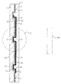
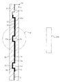
- FIG. 1 is an enlarged cross-sectional view taken along the line AA of FIG. BB enlarged sectional view of FIG.
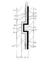
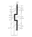
- FIG. 2 is an enlarged view of part C in FIG.
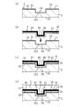
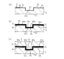
- (A) to (d) are process explanatory views explaining the manufacturing process of the first example of manufacturing the radome for the vehicle-mounted radar device of the first embodiment.
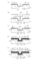
- (A) to (e) are process explanatory views explaining the manufacturing process of the 2nd example of manufacturing the radome for the vehicle-mounted radar apparatus of 1st Embodiment.
- FIG. 7 is an enlarged view of part D in FIG. (A) to (c) are process explanatory views explaining an example of a manufacturing process for manufacturing a radome for an in-vehicle radar device of the second embodiment.
- radome 1 for an in-vehicle radar device As shown in FIGS. 1 to 4, a transparent and electromagnetic wave transmitting front base material 2, a decorative layer 3, a heater layer 4, and an electromagnetic wave transmitting property are used.
- the rear base material 5 is fixedly provided so as to be in close contact with each other in order from the surface side.
- the front base material 2 in the illustrated example has an elliptical shape when viewed from the front, and the mark symbol portion 10 constituting the design portion can be visually recognized from the surface side through the transparent front base material 2.
- R in FIG. 1 is an electromagnetic wave transmission region.
- the shapes of the front base material 2 and the radome 1 are arbitrary as long as they can be applied in addition to the elliptical shape, and may be, for example, a square, a rectangle, a trapezoid, a perfect circle, or a triangle.
- the transparent front base material 2 and the back base material 5 are insulating and have electromagnetic wave transmission.
- the refractive index n defined based on the complex permittivity is consistent with each other, or the refractive index n is substantially the same or close to each other, for example, the front base material 2 and the back base material 5 are formed of the same material. Is suitable from the viewpoint of improving the transmission performance of electromagnetic waves.
- the numerical range of the refractive indexes n close to each other between the front base material 2 and the rear base material 5 it is preferable that the difference in the refractive indexes between the front base material 2 and the rear base material 5 is within the range of 0 to 10%.
- the refractive index n here is a quantity defined as Equation 1 from the relative permittivity real part ⁇ r'and the relative permittivity imaginary part ⁇ r ". From the viewpoint of transparency, the equation is based on the ratio of the imaginary part and the real part at the applicable frequency. It is preferable that the size of the dielectric tangent tan ⁇ defined as 2 is 0.1 or less, and the size of the real part of the relative permittivity is 3 or less. Dielectric tangent and non-dielectric constant By making the size of the real part smaller than these values, it is possible to ensure the reduction of the reflectance and the internal loss required for the redome.
- the transparent front base material 2 is preferably a colorless material or a colored material having a visible light transmittance of 50% or more in order to ensure good visibility.
- the material 2 is an insulating transparent synthetic resin
- the material is appropriate to the extent applicable, and is, for example, an acrylic resin such as polypropylene (PC) or polymethylmethacrylate (PMMA), or acrylonitrile-butadiene-styrene.
- PC polypropylene
- PMMA polymethylmethacrylate
- ABS polyethylene terephthalate
- PE polyethylene
- PP polypropylene
- AS acrylic nitrile-styrene copolymer
- PS polystyrene
- COP cycloolefin polymer
- the material is appropriate to the extent applicable, and for example, acrylics such as acrylonitrile-ethylenepropyl rubber-styrene copolymer (AES) and polymethylmethacrylate (PMMA).
- acrylics such as acrylonitrile-ethylenepropyl rubber-styrene copolymer (AES) and polymethylmethacrylate (PMMA).
- AES acrylonitrile-ethylenepropyl rubber-styrene copolymer
- PMMA polymethylmethacrylate
- One type of resin polycarbonate (PC), acryliconitrile-butadiene-styrene copolymer (ABS), acryliconitrile-styrene-acrylate copolymer (ASA), etc. can be used alone or in combination of two or more.
- Additives may be included.
- a decorative layer 3 is provided in close contact with the back surface 21 of the front base material 2, and the decorative layer 3 of the present embodiment is composed of an electromagnetic wave transmitting metal portion 31 and a colored portion 32.
- the decorative layer 3 is appropriate within the scope of the gist of the present invention, and other than the decorative layer 3 composed of the electromagnetic wave transmitting metal portion 31 and the colored portion 32, for example, only the electromagnetic wave transmitting metal portion is used. It can be a decorative layer composed of a colored portion, a decorative layer composed of only a colored portion, or the like.
- the electromagnetic wave transmitting metal portion 31 is composed of a discontinuous metal layer having electromagnetic wave transmission and metallic luster, has brilliant and integrated visibility, and is electroless plated, vapor-deposited, or deposited on the back surface 21 of the front base material 2. It is formed by spatter or the like.
- the electromagnetic wave transmitting metal portion 31 is a discontinuous metal layer having a brilliant and integrated visibility, for example, nickel or nickel alloy, chromium or chromium alloy, cobalt or cobalt alloy, tin or tin alloy, copper or copper alloy. , Silver or silver alloy, palladium or palladium alloy, platinum or platinum alloy, rhodium or rhodium alloy, gold or gold alloy and the like.
- the electromagnetic wave transmitting metal portion 31 shall be an appropriate electromagnetic wave transmitting metal portion within the scope of the present invention.
- a semiconductor layer such as silicon or germanium formed by vapor deposition or sputtering, or a metal having a visible light reflectance of 50% or more (for example, gold, silver, copper, aluminum, platinum, palladium, etc.). It can be an alloy layer with a bright metal such as iron, nickel, or chromium).
- a base layer for forming a modified surface that facilitates the formation of an electroless plating layer, or the like, if necessary, is transparent. It is also possible to provide a base layer such as a stratum.
- the colored portion 32 has electromagnetic wave transmission and is formed by printing, painting with a painting mask, or the like.
- the colored portion 32 is provided in close contact with the back surface 21 of the front base material 2 so as to be laminated on a part of the surface side of the electromagnetic wave transmitting metal portion 31.
- the electromagnetic wave transmitting metal portion 31 is formed in a layer over the entire region where the back surface 21 of the base material 2 is exposed and the region where the colored portion 32 is provided, and the back surface 21 of the front base material 2 is exposed. It is provided in close contact with the colored portion 32.
- a first recess 211 is formed on the back surface 21 side of the front base material 2 at a position corresponding to the mark symbol portion 10, and the decorative layer 3 is viewed in cross section so as to imitate the first recess 211. It is formed by partially protruding toward the surface and bending.
- the electromagnetic wave transmitting metal portion 31 of the decorative layer 3 is formed so as to partially project so as to imitate the first recess 211, and the colored portion 32 is not provided in the first recess 211, and the electromagnetic wave transmitting metal Only the part 31 is inserted and provided. Further, the colored portion 32 of the illustrated example is provided in close contact with the back surface 21 other than the first recess 211 of the front base material 2.
- a second recess 34 is provided on the back surface 33 side of the decorative layer 3 at a position corresponding to the first recess 211, and the heater layer 4 has a surface view in cross section so as to imitate the second recess 34. It is formed so as to be partially projected to the side and bent, and the protruding portion 43 is arranged so as to be engaged with the second recess 34.
- the heater layer 4 has a heater element 41, and is composed of an insulating film 42 and a heater element 41 fixed to the back surface side of the insulating film 42.
- the heater element 41 can be made of an appropriate conductive material such as nichrome wire, iron chromium, copper, silver, carbon fiber, and a transparent conductive film such as an ITO film.
- the heat resistant temperature of the decorative layer 3 is, for example, about 100 ° C.
- the heat resistant temperature of the front base material 2 such as PC is, for example, about 80 ° C., AES or the like. Since the heat-resistant temperature of the rear substrate 5 is, for example, about 80 ° C., the structure has good heat resistance to the temperature rise of the heater element 42.
- the insulating film 42 can be an insulating material having an appropriate electromagnetic wave transmittance applicable, and for example, polycarbonate (PC), polyethylene (PE), polypropylene (PP, OPP), polyethylene terephthalate (PET), and the like. It is preferably formed of an insulating synthetic resin such as polyethylene naphthalate (PEN), vinyl chloride (PVC), polystyrene (PS), acrylic (AC), or polyetheretherketone (PEEK). Further, the thickness of the insulating film 42 is preferably 0.05 to 1.0 mm from the viewpoint of increasing the thermal conductivity to the front base material 2 and protecting the heater element 41.
- PC polycarbonate
- PE polyethylene
- PP polypropylene
- PET polyethylene terephthalate
- PEN polyethylene naphthalate
- PVC vinyl chloride
- PS polystyrene
- AC acrylic
- PEEK polyetheretherketone
- the insulating film 42 has a refractive index n defined based on the complex permittivity of the front base material 2 and the rear base material 5 that are mutually matched, or have substantially the same or close refractive index n, electromagnetic waves are used. It is suitable from the viewpoint of improving the permeation performance of the film.
- the difference between the refractive index of the front base material 2 and the rear base material 5 and the refractive index of the insulating film 42 is 0 to 0 to It is good to keep it within the range of 10%.
- the refractive index n is also a quantity defined as Equation 1 from the relative permittivity real part ⁇ r'and the relative permittivity imaginary part ⁇ r'. Further, also in the insulating film 42, the imaginary part at the applicable frequency from the viewpoint of transparency. It is preferable that the magnitude of the dielectric constant tangent tan ⁇ defined as Equation 2 from the ratio of the real number part to 0.1 is 0.1 or less.
- Both ends of the heater element 41 of the heater layer 4 are electrically connected to the connector 6 and mechanically fixed, and power is supplied to the heater element 41 via the connector 6 so that the heater element 41 generates heat. It has become.
- the heater element 41 extending from the connector 6 in the present embodiment is formed by wiring so as to meander and fold back in the surface direction of the back surface 21 of the front base material 2 and extend in a series, and is adjacent to each other by the heater layer 4.
- the directions of the currents flowing through the heater elements 41 and 41 that are wired to each other are set to be substantially antiparallel or antiparallel to each other.
- heater elements 41 are arranged at a plurality of locations in the second recess 34 of the decorative layer 3 which are separated from each other in the surface direction of the front base material 2, and the heater elements 41 at the plurality of locations of the second recess 34 design the emblem. It is possible to surely melt the snow around the part and improve the visibility.
- the surface of the front base material 2 is used. It is preferable to set the distance L1 from 22 to the bottom located on the surface side of the first recess 211 to 0.1 to 10 mm, more preferably 0.7 mm to 8 mm, and even more preferably 1.5 mm to 4. It is recommended to set it to 5 mm.
- the third recess 45 on the back side of the heater layer 4 provided at a position corresponding to the second recess 34 of the decorative layer 3, in other words, the back side of the protrusion 43.
- a rear base material 5 for electromagnetic wave transmission is provided on the back surface side of the heater layer 4 so as to engage the convex portion 51.
- the radome 1 for the vehicle-mounted radar device is arranged in front of the vehicle-mounted radar device 100 and attached to the vehicle.
- the radome 1 for an in-vehicle radar device in the illustrated example is an emblem-shaped radome
- the radome for an in-vehicle radar device of the present invention can be configured by an appropriate vehicle-mounted component such as a bumper.
- the first recess 211 on the back surface 21 side of the electromagnetic wave transmitting front base material 2 is imitated.
- the decorative layer 3 is formed so as to partially project toward the surface side.
- the colored portion 32 is formed in a predetermined area on the back surface 21 of the front base material 2 by printing or painting with a coating mask, and then electroless plating, vapor deposition, sputtering, or the like.
- the electromagnetic wave transmitting metal portion 31 is formed over the entire surface including the inside of the first recess 211 on the back surface 21 of the front base material 2 (see FIG. 5A).
- a three-dimensional sheet-shaped heater layer 4 composed of an insulating film 42 and a heater element 41 fixed to the back surface side of the insulating film 42 and having a protruding portion 43 formed in advance in a predetermined region is used.
- a protruding portion 43 that partially protrudes toward the front surface side and is formed in a shape that imitates the second concave portion 34. Engage and fix the heater layer 4 to the decorative layer 3 (see FIGS. 5 (b) and 5 (c)).
- the adhesion of the heater layer 4 to the decorative layer 3 is preferably performed by heat welding or adhesion with an adhesive. Further, in the heater layer 4 in which the protruding portion 43 is formed in advance, the formation or drawing of the heater element 41 on the insulating film 42 may be performed by, for example, printing, vapor deposition, sputtering, plating, etching, MID, wire bonding, inkjet, dispenser, or the like. It is possible to do this using.
- the front base material 2 on which the decorative layer 3 is formed and the heater layer 4 is provided is arranged in the mold, and the heater layer is provided at a position corresponding to the second recess 34 of the decorative layer 3.
- a radome for an in-vehicle radar device is formed by injection molding on the back surface side of the heater layer 4 so that the convex portion 51 is engaged with the third concave portion 45 on the back surface side of the fourth. 1 is obtained (see FIG. 5 (d)).
- the electromagnetic wave transmitting front base material After forming the decorative layer 3 so as to partially project toward the front surface so as to follow the first recess 211 on the back surface 21 side of 2, a three-dimensional sheet shape in which a projecting portion 43 m is previously formed in a predetermined area. Insulating film 42 of the above, a shape that partially protrudes toward the surface side and follows the second recess 34 in the second recess 34 on the back surface side of the decorative layer 3 provided at a position corresponding to the first recess 211.
- the insulating film 42 is fixed to the decorative layer 3 by engaging the projecting portion 43 m formed in (see FIGS. 6 (b) and 6 (c)). Adhesion of the insulating film 42 to the decorative layer 3 is preferably performed by heat welding or adhesion with an adhesive.
- the heater element 41 is formed and fixed to the back side of the insulating film 42, and is composed of the insulating film 42 and the heater element 41 fixed to the back side of the insulating film 42.
- the heater layer 4 is formed.
- the formation or drawing of the heater element 41 on the insulating film 42 in this step can also be performed by using, for example, printing, vapor deposition, sputtering, plating, etching, wire bonding, an inkjet, or a dispenser.
- the front base material 2 on which the decorative layer 3 is formed and the heater layer 4 is provided is arranged in the mold, and the heater layer is provided at a position corresponding to the second recess 34 of the decorative layer 3.
- a radome for an in-vehicle radar device is formed by injection molding on the back surface side of the heater layer 4 so that the convex portion 51 is engaged with the third concave portion 45 on the back surface side of the fourth. 1 is obtained (see FIG. 6 (e)).
- the decorative layer 3 by providing the decorative layer 3 on the surface side of the heater layer 4, the decorative layer 3 constituting the design portion of the emblem or the like is good via the transparent front base material 2. Visibility can be ensured. Further, since the decorative layer 3 and the heater layer 4 are provided in close contact with each other without providing a gap or a base material between the decorative layer 3 and the heater layer 4, electromagnetic wave transmission can be improved. .. Further, since the front base material 2 and the decorative layer 3 are provided between the surface 22 of the transparent front base material 2 and the heater layer 4 without providing another base material, the front base material 2 is provided in front of the heater layer 4.
- the efficiency of heat conduction to the surface 22 of the base material 2 can be increased, and the snow and ice adhering to the outer surface of the radome 1 can be reliably melted. Further, at the positions corresponding to the first recess 211 and the second recess 34, the heater layer 4 partially protrudes toward the surface side, so that the occupied area of the surface 22 of the front base material 2 per unit area is not increased. It is possible to increase the density of the heater layer 4 or the heater element 41 thereof. Alternatively, it is also possible to perform the same snow melting as before with the heater element 41 having a narrow line width. As a result, it is possible to further improve the electromagnetic wave transmission while surely melting the snow.
- the heating of the heater layer 4 is thermally diffused by the thickness and spread of the front base material 2. Highly uniform snow melting can be performed over the entire surface 22 of the front base material 2. Further, since the base material is not provided between the decorative layer 3 and the heater layer 4, the molding process of the base material during this period can be eliminated, and the production can be performed with higher production efficiency.
- the convex portion of the rear base material 5 is provided.
- the portion 51 and the third recess 45 of the heater layer 4 can be engaged and fixed to be fixed with higher strength.
- the electromagnetic waves radiated from the adjacent heater elements 41 and 41 have opposite phases, and the heater elements The electromagnetic radiation from 41 can be canceled, and better electromagnetic wave transmission performance can be obtained.
- the electromagnetic wave transmission region R or the like by making the directions of the currents flowing through the heater elements 41 and 41, which are wired adjacent to each other, substantially antiparallel to each other, extremely excellent electromagnetic wave transmission performance can be obtained as a whole. Can be demonstrated.
- the decorative layer 3 having the electromagnetic wave transmitting metal portion 31 is ensured by the insulating film 42.
- the decorative layer 3 it is possible to prevent the decorative layer 3 from being electrically connected by energizing the heater element 41, and it is possible to reliably prevent the electromagnetic wave transmission from being lowered by the conduction of the decorative layer 3. ..
- the position of the heater element 41 can be prevented from being displaced, and the heater element 41 can be protected by the insulating film 42.
- the insulating film 42 functions as a base for fixing the heater element 41, and can increase the fixing strength of the heater element 41 to the decorative layer 3.
- a protruding portion 43 that partially protrudes on the surface side of the heater layer 4 and has a shape that imitates the second recess 34 is formed, and the insulating film 42 and its Using the heater layer 4 composed of the heater element 41 fixed to the back side, the protrusion 43 is engaged with the second recess 34 to fix the heater layer 4, so that the heater layer can be easily aligned.
- the insulating film 42 and the heater element 41 of No. 4 can be provided, and the manufacturing work can be facilitated.
- the heater layer 4 of the intermediate product can be obtained by forming the heater element 41 based only on the insulating film 42, it can be formed by using various manufacturing means, and the applicable manufacturing means. Can be diversified. Further, by engaging the convex portion 51 of the rear base material 5 with the third concave portion 45 on the back surface side of the heater layer 4 and injecting the rear base material 5 on the back surface side of the heater layer 4, the rear base material 5 is formed. A rear base material 5 having a high fixing strength in which the convex portion 51 of the heater layer 4 and the third concave portion 45 of the heater layer 4 are engaged and fixed can be provided on the back surface side.
- the insulating film 42 having a partially protruding portion on the surface side and a protruding portion 43 m having a shape following the second recess 34 is used, and the protruding portion 43 m. Is engaged with the second recess 34 to fix the insulating film 42, so that the insulating film 42 can be easily aligned and the insulating film 42 can be provided, and the manufacturing work can be facilitated. Further, by forming the heater element 41 on the back surface side of the insulating film 42 already fixed to the decorative layer 3, the heater element 41 can be stably installed at a more accurate position.
- a rear base material 5 having a high fixing strength in which the convex portion 51 of the heater layer 4 and the third concave portion 45 of the heater layer 4 are engaged and fixed can be provided on the back surface side.
- a transparent and electromagnetic wave transmitting front base material 2 a decorative layer 3, a heater layer 4a, and an electromagnetic wave transmitting property are used.
- the rear base material 5 is fixedly provided so as to be in close contact with each other in order from the surface side.
- the heater layer 4a is composed of only the heater element 41a.
- the heater layer 4a composed of only the heater element 41a is formed by being partially projected toward the surface side in a cross-sectional view so as to follow the second recess 34 provided at a position corresponding to the first recess 211, and is formed to project.
- the portion 43a is arranged so as to be engaged with the second recess 34.
- the heater element 41a is made of the same material as the heater element 41 of the first embodiment.
- both ends of the heater element 41a are electrically connected to the connector 6 and mechanically fixed, and power is supplied to the heater element 41a via the connector 6.
- the heater element 41a is designed to generate heat.
- the heater element 41a is formed by wiring so as to meander and fold back in the surface direction of the back surface 21 of the front base material 2 and extend in a series, and the heater elements 41a are wired adjacent to each other in the heater layer 4a.
- the directions of the currents flowing through 41a are set to be substantially antiparallel or antiparallel to each other (see FIG. 1).
- heater elements 41a are arranged at a plurality of locations in the second recess 34 of the decorative layer 3 which are separated from each other in the surface direction of the front base material 2, and the design of the emblem is provided by the heater elements 41a at the plurality of locations of the second recess 34. It is possible to surely melt the snow around the part and improve the visibility.
- the distance L1 to the bottom located on the surface side of the first recess 211 is set to 0.1 to 10 mm, more preferably 0.7 mm to 8 mm, and even more preferably 1.5 mm to 4.5 mm. It is good to set.
- the distance L2 from the tip of the partially protruding protrusion 43a of the heater layer 4a to the rearmost surface 44a other than the protruding portion 43a of the heater layer 4a is 1 to 10 mm, and 1.5 mm to 4 It is more preferable to set it to 5.5 mm.
- the convex portion 51 is engaged with the second concave portion 34 of the portion where the heater layer 4a or the heater element 41a is not provided or is provided only partially.
- a rear base material 5 that transmits electromagnetic waves is provided on the back surface side of the heater layer 4a.
- the radome 1a for the vehicle-mounted radar device is also arranged in front of the vehicle-mounted radar device 100 and attached to the vehicle.
- the radome for an in-vehicle radar device of the present invention having the configuration of the radome 1a for an in-vehicle radar device can also be composed of appropriate vehicle-mounted parts such as an emblem and a bumper.
- the other configurations of the radome 1a for the vehicle-mounted radar device of the second embodiment are the same as those of the radome 1 for the vehicle-mounted radar device of the first embodiment.
- the surface of the radome 1 for an in-vehicle radar device follows the first recess 211 on the back surface 21 side of the electromagnetic wave transmitting front base material 2.
- the decorative layer 3 is formed so as to partially project to the side.
- the step of forming the decorative layer 3 is the same as that of the first and second examples of the first embodiment.
- the colored portion 32 is printed or painted with a painting mask on the back surface of the front base material 2.
- the electromagnetic wave transmitting metal portion 31 is formed over the entire surface including the inside of the first recess 211 on the back surface 21 of the front base material 2 by electroless plating, vapor deposition, sputtering, or the like (FIG. 9 (a)).
- the heater element 41a constituting the heater layer 4a is formed in close contact with the back surface of the decorative layer 3 by engaging the portions 43a (see FIG. 9B).
- the formation or drawing of the heater element 41a on the decorative layer 3 in this step can be performed by using, for example, printing, vapor deposition, sputtering, plating, etching, wire bonding, an inkjet, or a dispenser.
- the front base material 2 on which the decorative layer 3 is formed and the heater layer 4a is provided is arranged in the mold, and the heater layer is provided at a position corresponding to the second recess 34 of the decorative layer 3.
- the convex portion 51 is engaged with the third concave portion 45a on the back surface side of the 4a and the second concave portion 34 where the heater element 41a is not provided or is provided only partially.
- a rear base material 5 for electromagnetic wave transmission is formed on the back surface side of the heater layer 4a by injection molding to obtain a radome 1a for an in-vehicle radar device (see FIG. 9C).
- the corresponding effect can be obtained from the configuration corresponding to the first embodiment, and the heater element 41a is directly brought into close contact with the decorative layer 3, and the surface of the front base material 2 from the heater layer 4a.
- the efficiency of heat conduction to 22 can be further increased, and snow and ice adhering to the outer surface of the radome can be more reliably melted.
- the heater element 41a by forming the heater element 41a directly on the back surface 33 of the decorative layer 3, the heater element 41a is stabilized at a more accurate position on the back surface 33 of the decorative layer 3. Can be installed. Further, the convex portion 51 of the rear base material 5 is engaged with the third concave portion 45a on the back surface side of the heater layer 4a and the second concave portion 34 in which the heater element 41a is not provided or is provided only partially. In addition, by injection molding the rear base material 5 on the back surface side of the heater layer 4a, the convex portion 51 of the rear base material 5, the third concave portion 45a, and the second concave portion 24 are engaged and fixed to each other to have a high fixing strength. The rear base material 5 can be provided on the back side.
- the shapes and numbers of the first recess on the back side of the front base material, the second recess on the back side of the decorative layer, and the third recess on the back side of the heater layer in the radome for an in-vehicle radar device of the present invention are applicable. It is appropriate to the extent possible, and it is possible to provide one or more recesses having a required shape such as a groove shape or a bowl shape, respectively.
- the present invention also includes a structure in which a recess not corresponding to the first recess is provided on the back surface side of the front base material.
- the radome for an in-vehicle radar device of the present invention is preferably configured such that the directions of currents flowing through the heater wires wired adjacent to each other are substantially antiparallel or antiparallel to each other, but they are wired adjacent to each other. It also includes the case where the directions of the currents flowing through the heater wires are substantially antiparallel or not antiparallel to each other.
- the electromagnetic wave of the radar targeted by the radome for the in-vehicle radar device of the present invention is appropriate within an applicable range, and the 24/26 GHz band, 76/77 GHz band, 77/81 GHz band, etc., which are practically used as in-vehicle radars, etc.
- the present invention can be applied to electromagnetic waves for radar other than these.
- the present invention can be similarly applied when a radar having a shorter wavelength is put into practical use.
- the wiring pattern and wiring configuration of the heater element in the present invention are not limited to the wiring configuration of the heater elements 41 and 41a, and are appropriate within the scope of the purpose of the present invention.
- the heaters are concentric or concentric.
- the element may be wired, or the heater element may be wired so as to extend substantially radially from the center.
- the present invention can be used for a radome for an in-vehicle radar device.
- Electromagnetic wave transmitting metal part 32 ... Colored part 33 ... Back side 34 ... Second Recesses 4, 4a ... Heater layer 41, 41a ... Heater element 42 ... Insulating film 43, 43m, 43a ... Protruding parts 44, 44a ... Backmost 45, 45a ... Third recess 5 ... Rear base material 51 ... Convex 6 ... Connector 10 ... Mark symbol part 100 ... In-vehicle radar device R ... Electromagnetic wave transmission region L1 ... Distance from the surface of the front base material to the bottom located on the surface side of the first recess L2 ... Part of the heater layer The tip of the protruding part Distance from to the backmost surface other than the protruding part of the heater layer
Landscapes
- Engineering & Computer Science (AREA)
- Radar, Positioning & Navigation (AREA)
- Remote Sensing (AREA)
- Physics & Mathematics (AREA)
- Computer Networks & Wireless Communication (AREA)
- General Physics & Mathematics (AREA)
- Mechanical Engineering (AREA)
- Electromagnetism (AREA)
- Radar Systems Or Details Thereof (AREA)
- Details Of Aerials (AREA)
- Vehicle Waterproofing, Decoration, And Sanitation Devices (AREA)
Applications Claiming Priority (2)
| Application Number | Priority Date | Filing Date | Title |
|---|---|---|---|
| JP2019-078631 | 2019-04-17 | ||
| JP2019078631A JP7261648B2 (ja) | 2019-04-17 | 2019-04-17 | 車載レーダー装置用レドームの製造方法 |
Publications (1)
| Publication Number | Publication Date |
|---|---|
| WO2020213309A1 true WO2020213309A1 (ja) | 2020-10-22 |
Family
ID=72836762
Family Applications (1)
| Application Number | Title | Priority Date | Filing Date |
|---|---|---|---|
| PCT/JP2020/010599 Ceased WO2020213309A1 (ja) | 2019-04-17 | 2020-03-11 | 車載レーダー装置用レドーム及びその製造方法 |
Country Status (2)
| Country | Link |
|---|---|
| JP (1) | JP7261648B2 (enExample) |
| WO (1) | WO2020213309A1 (enExample) |
Cited By (1)
| Publication number | Priority date | Publication date | Assignee | Title |
|---|---|---|---|---|
| US20220268605A1 (en) * | 2021-02-24 | 2022-08-25 | Toyoda Gosei Co., Ltd. | Electromagnetic wave sensor cover |
Families Citing this family (7)
| Publication number | Priority date | Publication date | Assignee | Title |
|---|---|---|---|---|
| JP7418906B2 (ja) * | 2019-09-09 | 2024-01-22 | 三恵技研工業株式会社 | 車載レーダー装置用レドームの製造方法 |
| US20240243464A1 (en) * | 2021-02-19 | 2024-07-18 | Asahi Kasei Kabushiki Kaisha | Cover |
| JP2021170006A (ja) * | 2021-03-02 | 2021-10-28 | 三恵技研工業株式会社 | 車載レーダー装置用レドーム及びその製造方法 |
| WO2022185764A1 (ja) * | 2021-03-02 | 2022-09-09 | 三恵技研工業株式会社 | 車載レーダー装置用レドーム及びその製造方法 |
| JP7501431B2 (ja) * | 2021-03-31 | 2024-06-18 | 豊田合成株式会社 | 車両用加熱対象部品及びその製造方法 |
| JP7100327B1 (ja) | 2021-04-19 | 2022-07-13 | 南部化成株式会社 | ヒーター内蔵車両用エンブレムおよびその製造方法 |
| KR102477745B1 (ko) * | 2021-07-02 | 2022-12-15 | 인탑스 주식회사 | 발열체를 포함하는 수지 사출물의 제조방법 |
Citations (4)
| Publication number | Priority date | Publication date | Assignee | Title |
|---|---|---|---|---|
| JP2015099081A (ja) * | 2013-11-19 | 2015-05-28 | 豊田合成株式会社 | 電波透過カバー及び電波透過カバーの製造方法 |
| DE102014002438A1 (de) * | 2014-02-20 | 2015-08-20 | Daimler Ag | Herstellverfahren für ein Kunststoff-Radom eines Kraftfahrzeugs |
| JP2017215242A (ja) * | 2016-06-01 | 2017-12-07 | 豊田合成株式会社 | 車両用装飾部品 |
| JP2018066706A (ja) * | 2016-10-21 | 2018-04-26 | 豊田合成株式会社 | 車両用装飾部品及びその製造方法 |
Family Cites Families (4)
| Publication number | Priority date | Publication date | Assignee | Title |
|---|---|---|---|---|
| JPS5321634B2 (enExample) * | 1972-10-18 | 1978-07-04 | ||
| DE19963004A1 (de) | 1999-12-24 | 2001-06-28 | Bosch Gmbh Robert | Kraftfahrzeug-Radarsystem |
| DE10026454C1 (de) | 2000-05-27 | 2001-12-20 | Daimler Chrysler Ag | Radom für ein Abstands-Warn-Radar (AWR) |
| JP3843994B2 (ja) | 2004-11-01 | 2006-11-08 | 株式会社村田製作所 | 誘電体レンズアンテナおよびそれを用いた無線装置 |
-
2019
- 2019-04-17 JP JP2019078631A patent/JP7261648B2/ja active Active
-
2020
- 2020-03-11 WO PCT/JP2020/010599 patent/WO2020213309A1/ja not_active Ceased
Patent Citations (4)
| Publication number | Priority date | Publication date | Assignee | Title |
|---|---|---|---|---|
| JP2015099081A (ja) * | 2013-11-19 | 2015-05-28 | 豊田合成株式会社 | 電波透過カバー及び電波透過カバーの製造方法 |
| DE102014002438A1 (de) * | 2014-02-20 | 2015-08-20 | Daimler Ag | Herstellverfahren für ein Kunststoff-Radom eines Kraftfahrzeugs |
| JP2017215242A (ja) * | 2016-06-01 | 2017-12-07 | 豊田合成株式会社 | 車両用装飾部品 |
| JP2018066706A (ja) * | 2016-10-21 | 2018-04-26 | 豊田合成株式会社 | 車両用装飾部品及びその製造方法 |
Cited By (3)
| Publication number | Priority date | Publication date | Assignee | Title |
|---|---|---|---|---|
| US20220268605A1 (en) * | 2021-02-24 | 2022-08-25 | Toyoda Gosei Co., Ltd. | Electromagnetic wave sensor cover |
| CN114954257A (zh) * | 2021-02-24 | 2022-08-30 | 丰田合成株式会社 | 电磁波传感器罩 |
| US12098999B2 (en) * | 2021-02-24 | 2024-09-24 | Toyoda Gosei Co., Ltd. | Electromagnetic wave sensor cover |
Also Published As
| Publication number | Publication date |
|---|---|
| JP2020176895A (ja) | 2020-10-29 |
| JP7261648B2 (ja) | 2023-04-20 |
Similar Documents
| Publication | Publication Date | Title |
|---|---|---|
| WO2020213309A1 (ja) | 車載レーダー装置用レドーム及びその製造方法 | |
| JP7418906B2 (ja) | 車載レーダー装置用レドームの製造方法 | |
| JP7094911B2 (ja) | 車載レーダー装置用レドーム | |
| JP7313106B2 (ja) | 車載レーダー装置用レドーム | |
| JP7312608B2 (ja) | 車両用装飾部品 | |
| CN107444289B (zh) | 车辆用装饰件 | |
| JP6665691B2 (ja) | 車両用装飾部品 | |
| JP6658313B2 (ja) | 車両用装飾部品 | |
| KR102160944B1 (ko) | 차량 주행 제어용 센서 커버 및 그 제조방법 | |
| WO2018074118A1 (ja) | 車両用装飾部品及びその製造方法 | |
| JP2014069634A (ja) | 車両用加飾部材 | |
| JP7755762B2 (ja) | 車載レーダー装置用レドーム及び車載レーダー構造 | |
| JP7243681B2 (ja) | 車両用外装品 | |
| JP2020176895A5 (enExample) | ||
| JP7031434B2 (ja) | 車両用装飾部品及び車両用装飾部品の製造方法 | |
| JP2020187032A (ja) | 車両用装飾部品 | |
| JP7431014B2 (ja) | 車載レーダー装置用レドーム | |
| EP3912227B1 (en) | Cover for an antenna and method of producing such a cover | |
| JP7618410B2 (ja) | 車載レーダー装置用レドーム構造及びその製造方法 | |
| CN121128314A (zh) | 用于制备薄膜体的方法及设备、薄膜体、用于制备层复合体的方法、层复合体、用于制备加热薄膜复合体的方法、加热薄膜复合体以及设备 | |
| JP7759165B2 (ja) | 車載レーダー装置用レドーム及びその製造方法 | |
| JP2025150774A (ja) | 車載レーダー装置用レドーム及びその製造方法 | |
| JP7522969B2 (ja) | 電磁波透過カバー | |
| JP2025109516A (ja) | 車両用外装品 | |
| CN119452042A (zh) | 树脂成型体以及树脂成型体的制造方法 |
Legal Events
| Date | Code | Title | Description |
|---|---|---|---|
| 121 | Ep: the epo has been informed by wipo that ep was designated in this application |
Ref document number: 20791915 Country of ref document: EP Kind code of ref document: A1 |
|
| NENP | Non-entry into the national phase |
Ref country code: DE |
|
| 122 | Ep: pct application non-entry in european phase |
Ref document number: 20791915 Country of ref document: EP Kind code of ref document: A1 |