WO2020213309A1 - Radome for vehicle-mounted radar device and method for manufacturing same - Google Patents
Radome for vehicle-mounted radar device and method for manufacturing same Download PDFInfo
- Publication number
- WO2020213309A1 WO2020213309A1 PCT/JP2020/010599 JP2020010599W WO2020213309A1 WO 2020213309 A1 WO2020213309 A1 WO 2020213309A1 JP 2020010599 W JP2020010599 W JP 2020010599W WO 2020213309 A1 WO2020213309 A1 WO 2020213309A1
- Authority
- WO
- WIPO (PCT)
- Prior art keywords
- surface side
- heater
- layer
- recess
- base material
- Prior art date
Links
Images


Classifications
-
- B—PERFORMING OPERATIONS; TRANSPORTING
- B60—VEHICLES IN GENERAL
- B60R—VEHICLES, VEHICLE FITTINGS, OR VEHICLE PARTS, NOT OTHERWISE PROVIDED FOR
- B60R13/00—Elements for body-finishing, identifying, or decorating; Arrangements or adaptations for advertising purposes
-
- G—PHYSICS
- G01—MEASURING; TESTING
- G01S—RADIO DIRECTION-FINDING; RADIO NAVIGATION; DETERMINING DISTANCE OR VELOCITY BY USE OF RADIO WAVES; LOCATING OR PRESENCE-DETECTING BY USE OF THE REFLECTION OR RERADIATION OF RADIO WAVES; ANALOGOUS ARRANGEMENTS USING OTHER WAVES
- G01S13/00—Systems using the reflection or reradiation of radio waves, e.g. radar systems; Analogous systems using reflection or reradiation of waves whose nature or wavelength is irrelevant or unspecified
- G01S13/88—Radar or analogous systems specially adapted for specific applications
- G01S13/93—Radar or analogous systems specially adapted for specific applications for anti-collision purposes
- G01S13/931—Radar or analogous systems specially adapted for specific applications for anti-collision purposes of land vehicles
-
- G—PHYSICS
- G01—MEASURING; TESTING
- G01S—RADIO DIRECTION-FINDING; RADIO NAVIGATION; DETERMINING DISTANCE OR VELOCITY BY USE OF RADIO WAVES; LOCATING OR PRESENCE-DETECTING BY USE OF THE REFLECTION OR RERADIATION OF RADIO WAVES; ANALOGOUS ARRANGEMENTS USING OTHER WAVES
- G01S7/00—Details of systems according to groups G01S13/00, G01S15/00, G01S17/00
- G01S7/02—Details of systems according to groups G01S13/00, G01S15/00, G01S17/00 of systems according to group G01S13/00
- G01S7/03—Details of HF subsystems specially adapted therefor, e.g. common to transmitter and receiver
-
- H—ELECTRICITY
- H01—ELECTRIC ELEMENTS
- H01Q—ANTENNAS, i.e. RADIO AERIALS
- H01Q1/00—Details of, or arrangements associated with, antennas
- H01Q1/42—Housings not intimately mechanically associated with radiating elements, e.g. radome
Abstract
In a radome 1 for a vehicle-mounted radar device, a transparent, electromagnetic-wave-transmitting front substrate 2, a decorative layer 3, and a heater layer 4 are provided in close contact and in order from a front-surface side. The decorative layer 3 is formed so as to partially protrude toward the front-surface side so as to follow a first recess part 211 on the rear-surface 21 side of the front substrate 2. The heater layer 4 is formed so as to partially protrude toward the front-surface side so as to follow a second recess part 34 provided on the rear-surface side of the decorative layer 3 at a position corresponding to the first recess part 211. Provided is a radome for a vehicle-mounted radar device that is capable of: ensuring good visibility of a decorative layer, which forms an emblem design part or the like; enhancing electromagnetic wave transmission; and reliably melting snow adhered to the outer surface of the radome with high heat transfer efficiency.
Description
本発明は、車載レーダー装置の前側に設けられる車載レーダー装置用レドームに係り、特に融雪機能を有する車載レーダー装置用レドーム及びその製造方法に関する。
The present invention relates to a radome for an in-vehicle radar device provided on the front side of the in-vehicle radar device, and particularly relates to a radome for an in-vehicle radar device having a snow melting function and a method for manufacturing the radome.
従来、車載レーダー装置用レドームとして、必要な電磁波の透過性の確保を図りつつ、融雪機能を発揮するレドームが知られている。このようなレドームとして、加飾層の後側にヒーター層を設け、加飾層の良好な視認性を確保できる特許文献1のレドームがある。特許文献1のレドームは、透明基板と、透明基板の後側に配置される第1基材及び第2基材を有し、透明基板と第1基材の間に加飾層が形成され、第1基材と第2基材がヒーター層を前後から挟み込んで密封するようにして相互に接合されるものであり、表面側から順に透明基板、加飾層、第1基材、ヒーター層、第2基材が設けられる構造になっている。
Conventionally, as a radome for an in-vehicle radar device, a radome that exhibits a snow melting function while ensuring the necessary electromagnetic wave transmission is known. As such a radome, there is a radome of Patent Document 1 in which a heater layer is provided on the rear side of the decorative layer to ensure good visibility of the decorative layer. The redome of Patent Document 1 has a transparent substrate and a first base material and a second base material arranged behind the transparent substrate, and a decorative layer is formed between the transparent substrate and the first base material. The first base material and the second base material are joined to each other by sandwiching the heater layer from the front and back and sealing them, and the transparent substrate, the decorative layer, the first base material, the heater layer, etc. It has a structure in which a second base material is provided.
また、特許文献1には、従来例のレドームとして、表面側から順に透明基板、加飾層、空隙部、ヒーター層、基材が設けられる構造も開示されている。この従来例のレドームは、透明基板及び基材の比誘電率と大きく異なる空隙部内の空気の比誘電率により、電磁波透過性能が低下することが指摘されている(特許文献1の段落[0004]、[0010]、図10(b)参照)。
Further, Patent Document 1 also discloses a structure in which a transparent substrate, a decorative layer, a void portion, a heater layer, and a base material are provided in order from the surface side as a conventional radome. It has been pointed out that the electromagnetic wave transmission performance of this conventional radome is lowered due to the relative permittivity of air in the voids, which is significantly different from the relative permittivity of the transparent substrate and the base material (Patent Document 1 paragraph [0004]. , [0010], see FIG. 10 (b)).
ところで、特許文献1のレドームは、上記従来例のレドームの空隙部に相当する部位に第2基材と同一樹脂材料の第1基材を配置する構造により、電磁波透過性能の低下を抑制することが可能である。しかしながら、特許文献1のレドームは、透明基板の表面とヒーター層との間に透明基板、加飾層、第1基材が配置される構造のため、ヒーター層から雪が付着する透明基板の表面までの距離が長くなり、熱伝導効率が低下するという問題がある。
By the way, the radome of Patent Document 1 suppresses a decrease in electromagnetic wave transmission performance by a structure in which a first base material of the same resin material as the second base material is arranged in a portion corresponding to a gap portion of the radome of the above-mentioned conventional example. Is possible. However, since the redome of Patent Document 1 has a structure in which the transparent substrate, the decorative layer, and the first base material are arranged between the surface of the transparent substrate and the heater layer, from the heater layer to the surface of the transparent substrate to which snow adheres. There is a problem that the distance between the two is increased and the heat conduction efficiency is lowered.
本発明は上記課題に鑑み提案するものであり、エンブレムの意匠部等を構成する加飾層の良好な視認性の確保、電磁波透過性の向上を図ることができると共に、高い熱伝導効率でレドームの外表面に付着した雪を確実に融雪することができる車載レーダー装置用レドーム及びその製造方法を提供することを目的とする。
The present invention has been proposed in view of the above problems, and it is possible to ensure good visibility of the decorative layer constituting the design portion of the emblem, improve electromagnetic wave transmission, and achieve a radome with high heat conduction efficiency. It is an object of the present invention to provide a radome for an in-vehicle radar device capable of reliably melting snow adhering to the outer surface of the radome and a method for manufacturing the radome.
本発明の車載レーダー装置用レドームは、透明で電磁波透過性の前基材と、加飾層と、ヒーター層が表面側から順に密接して設けられ、前記前基材の背面側の第1の凹部に倣うように表面側に部分突出して前記加飾層が形成され、前記第1の凹部に対応する位置に設けられる前記加飾層の背面側の第2の凹部に倣うように表面側に部分突出して前記ヒーター層が設けられていることを特徴とする。
これによれば、ヒーター層の表面側に加飾層が設けられることにより、透明な前基材を介して、エンブレムの意匠部等を構成する加飾層の良好な視認性を確保することができる。また、加飾層とヒーター層との間に空隙部や基材が設けられずに、加飾層とヒーター層が密接して設けられるため、電磁波透過性を向上することができる。また、透明な前基材の表面とヒーター層との間に、別の基材が設けられずに、前基材と加飾層が設けられることから、ヒーター層から前基材の表面への熱伝導効率を高めることができ、レドームの外表面に付着した雪や氷を確実に融雪することができる。また、第1の凹部、第2の凹部に対応する位置では、ヒーター層が表面側に部分突出することにより、前基材の表面の単位面積当たりの占有面積を増やさずにヒーター層或いはそのヒーターエレメントの密度を高めることが可能となる。これにより、確実な融雪を行いつつ、電磁波透過性を一層向上することができる。また、前基材の表面とヒーター層との間には前基材が設置されていることから、前基材の厚みや広がりでヒーター層の加熱を熱拡散して、前基材の表面全体に亘って均一性の高い融雪を行うことができる。また、加飾層とヒーター層との間に基材を設けない構成であることから、この間の基材の成形工程を無くすことができ、より高い製造効率で製造することができる。 In the radome for an in-vehicle radar device of the present invention, a transparent and electromagnetic wave transmitting front base material, a decorative layer, and a heater layer are provided in close contact with each other in order from the front surface side, and the first first base material on the back surface side of the front base material. The decorative layer is formed so as to partially project to the surface side so as to imitate the concave portion, and to the surface side so as to imitate the second concave portion on the back surface side of the decorative layer provided at a position corresponding to the first concave portion. It is characterized in that the heater layer is provided so as to partially project.
According to this, by providing the decorative layer on the surface side of the heater layer, it is possible to ensure good visibility of the decorative layer constituting the design portion of the emblem or the like through the transparent front base material. it can. Further, since the decorative layer and the heater layer are provided in close contact with each other without providing a gap or a base material between the decorative layer and the heater layer, electromagnetic wave transmission can be improved. Further, since the front base material and the decorative layer are provided between the surface of the transparent front base material and the heater layer without providing another base material, the heater layer can be transferred to the surface of the front base material. The heat conduction efficiency can be increased, and the snow and ice adhering to the outer surface of the radome can be reliably melted. Further, at the positions corresponding to the first recess and the second recess, the heater layer partially protrudes toward the surface side, so that the heater layer or its heater does not increase the occupied area per unit area of the surface of the front base material. It is possible to increase the density of elements. As a result, it is possible to further improve the electromagnetic wave transmission while surely melting the snow. Further, since the front base material is installed between the surface of the front base material and the heater layer, the heating of the heater layer is thermally diffused by the thickness and spread of the front base material, and the entire surface of the front base material is obtained. It is possible to melt snow with high uniformity. Further, since the base material is not provided between the decorative layer and the heater layer, the molding process of the base material during this period can be eliminated, and the production can be performed with higher production efficiency.
本発明の車載レーダー装置用レドームは、前記第2の凹部に対応する位置に設けられる前記ヒーター層の背面側の第3の凹部に凸部を係合するようにして前記ヒーター層の背面側に電磁波透過性の後基材が設けられていることを特徴とする。
これによれば、ヒーター層の背面側の第3の凹部に後基材の凸部を係合してヒーター層の背面側に後基材を設けることにより、後基材の凸部とヒーター層の第3の凹部を係合固着してより高い強度で固定することができる。 The radome for an in-vehicle radar device of the present invention is provided on the back side of the heater layer so as to engage a convex portion with a third recess on the back side of the heater layer provided at a position corresponding to the second recess. It is characterized in that a base material is provided after the electromagnetic wave transmission.
According to this, the convex portion of the rear base material and the heater layer are provided by engaging the convex portion of the rear base material with the third concave portion on the back surface side of the heater layer to provide the rear base material on the back surface side of the heater layer. The third recess of the above can be engaged and fixed to be fixed with higher strength.
本発明の車載レーダー装置用レドームは、前記ヒーター層における隣り合って配線されているヒーターエレメントに流れる電流の方向が互いに略反平行であることを特徴とする。
これによれば、隣り合うヒーターエレメントに流れる電流の方向が互いに略反平行のなるようにすることで、隣り合うヒーターエレメントから放射される電磁波を逆位相とし、ヒーターエレメントからの電磁放射を打ち消すことができ、より優れた電磁波透過性能を得ることができる。特に、隣り合って配線されている各々のヒーターエレメントに流れる電流の方向を互いに略反平行にすることにより、全体に亘って非常に優れた電磁波透過性能を発揮することができる。 The radome for an in-vehicle radar device of the present invention is characterized in that the directions of currents flowing through adjacently wired heater elements in the heater layer are substantially antiparallel to each other.
According to this, by making the directions of the currents flowing through the adjacent heater elements substantially antiparallel to each other, the electromagnetic waves radiated from the adjacent heater elements are in opposite phase, and the electromagnetic radiation from the heater elements is canceled. It is possible to obtain better electromagnetic wave transmission performance. In particular, by making the directions of the currents flowing through the heater elements wired adjacent to each other substantially antiparallel to each other, it is possible to exhibit extremely excellent electromagnetic wave transmission performance as a whole.
本発明の車載レーダー装置用レドームは、前記ヒーター層が絶縁フィルムと前記絶縁フィルムの背面側に固着されたヒーターエレメントから構成されることを特徴とする。
これによれば、絶縁フィルムによる絶縁性担保により、加飾層の構成に拘わらず、ヒーターエレメントへの通電で加飾層に導通が発生することを防止でき、加飾層の導通で電磁波透過性が低下することを確実に防止できる。また、絶縁フィルムにヒーターエレメントを固着することにより、ヒーターエレメントの位置ズレを防止できると共に、絶縁フィルムでヒーターエレメントを保護することもできる。また、絶縁フィルムはヒーターエレメントを固着する下地として機能し、ヒーターエレメントの加飾層への固着強度を高めることができる。 The radome for an in-vehicle radar device of the present invention is characterized in that the heater layer is composed of an insulating film and a heater element fixed to the back surface side of the insulating film.
According to this, by guaranteeing the insulation property by the insulating film, it is possible to prevent the decorative layer from being conductive by energizing the heater element regardless of the configuration of the decorative layer, and the conduction of the decorative layer is electromagnetic wave transmission. Can be reliably prevented from decreasing. Further, by fixing the heater element to the insulating film, the position of the heater element can be prevented from being displaced, and the heater element can be protected by the insulating film. Further, the insulating film functions as a base for fixing the heater element, and can increase the fixing strength of the heater element to the decorative layer.
本発明の車載レーダー装置用レドームは、前記ヒーター層がヒーターエレメントだけで構成されることを特徴とする。
これによれば、ヒーターエレメントを直接加飾層に密接させ、ヒーター層から前基材の表面への熱伝導効率をより高めることができ、レドームの外表面に付着した雪をより確実に融雪することができる。 The radome for an in-vehicle radar device of the present invention is characterized in that the heater layer is composed of only a heater element.
According to this, the heater element can be brought into close contact with the decorative layer directly, the heat conduction efficiency from the heater layer to the surface of the front base material can be further increased, and the snow adhering to the outer surface of the radome is more reliably melted. be able to.
本発明の車載レーダー装置用レドームは、前記前基材の表面から前記第1の凹部の表面側に位置する底までの距離が0.1~10mmに設定され、前記ヒーター層の部分突出する突出部の先端から前記ヒーター層の前記突出部以外の最背面までの距離が1~10mmに設定されていることを特徴とする。
これによれば、よりバランス良く熱拡散の均一性の向上と熱伝導効率の向上を図り、前基材の表面全体に亘って均一性の高い確実な融雪を行うことができる。 In the radome for an in-vehicle radar device of the present invention, the distance from the surface of the front base material to the bottom located on the surface side of the first recess is set to 0.1 to 10 mm, and the heater layer partially protrudes. The distance from the tip of the portion to the innermost back surface of the heater layer other than the protruding portion is set to 1 to 10 mm.
According to this, it is possible to improve the uniformity of heat diffusion and the efficiency of heat conduction in a more balanced manner, and to perform reliable snow melting with high uniformity over the entire surface of the front base material.
本発明の車載レーダー装置用レドームの製造方法は、本発明の車載レーダー装置用レドームを製造する方法であって、電磁波透過性の前基材の背面側の第1の凹部に倣って表面側に部分突出するように加飾層を形成する第1工程と、前記第1の凹部に対応する位置に設けられている前記加飾層の背面側の第2の凹部に、表面側に部分突出し且つ前記第2の凹部に倣う形状で形成されている突出部を係合して、絶縁フィルムと前記絶縁フィルムの背面側に固着されたヒーターエレメントから構成されるヒーター層を前記加飾層に固着する第2工程と、前記加飾層が形成され且つ前記ヒーター層が設けられた前記前基材を金型内に配置し、前記第2の凹部に対応する位置に設けられている前記ヒーター層の背面側の第3の凹部に凸部を係合するようにして前記ヒーター層の背面側に電磁波透過性の後基材を射出成形で形成する第3工程を備えることを特徴とする。
これによれば、ヒーター層の表面側に部分突出し且つ第2の凹部に倣う形状の突出部が形成され、絶縁フィルムとその背面側に固着されたヒーターエレメントから構成されるヒーター層を用い、突出部を第2の凹部に係合してヒーター層を固着することにより、容易に位置合わせしてヒーター層の絶縁フィルムとヒーターエレメントを設けることができ、製造作業を容易化することができる。また、中間品のヒーター層は、絶縁フィルムだけを基にしてヒーターエレメントを形成して得ることができることから、多様な製造手段を用いて形成することが可能となり、適用可能な製造手段の多様化を図ることができる。また、ヒーター層の背面側の第3の凹部に後基材の凸部を係合してヒーター層の背面側に後基材を射出成形することにより、後基材の凸部とヒーター層の第3の凹部を係合固着した高い固着強度の後基材を背面側に設けることができる。 The method for manufacturing a radome for an in-vehicle radar device of the present invention is a method for manufacturing a radome for an in-vehicle radar device of the present invention, which follows the first recess on the back side of the electromagnetic wave transmitting front base material and forms a surface side. The first step of forming the decorative layer so as to partially project, and the second recess on the back side of the decorative layer provided at a position corresponding to the first recess, the decorative layer partially projects toward the front surface. A heater layer composed of an insulating film and a heater element fixed to the back surface side of the insulating film is fixed to the decorative layer by engaging a protruding portion formed in a shape that imitates the second recess. In the second step, the front base material on which the decorative layer is formed and the heater layer is provided is arranged in a mold, and the heater layer is provided at a position corresponding to the second recess. It is characterized by comprising a third step of forming an electromagnetic wave transmitting rear substrate by injection molding on the back surface side of the heater layer so as to engage a convex portion with the third concave portion on the back surface side.
According to this, a protruding portion that partially protrudes on the surface side of the heater layer and has a shape that imitates the second recess is formed, and the heater layer composed of the insulating film and the heater element fixed to the back side thereof is used to project. By engaging the portion with the second recess and fixing the heater layer, the insulating film of the heater layer and the heater element can be easily aligned, and the manufacturing work can be facilitated. Further, since the heater layer of the intermediate product can be obtained by forming the heater element based only on the insulating film, it can be formed by using various manufacturing means, and the applicable manufacturing means are diversified. Can be planned. Further, by engaging the convex portion of the rear base material with the third concave portion on the back surface side of the heater layer and injection molding the rear base material on the back surface side of the heater layer, the convex portion of the rear base material and the heater layer are formed. After the high fixing strength in which the third recess is engaged and fixed, the base material can be provided on the back surface side.
本発明の車載レーダー装置用レドームの製造方法は、本発明の車載レーダー装置用レドームを製造する方法であって、電磁波透過性の前基材の背面側の第1の凹部に倣って表面側に部分突出するように加飾層を形成する第1工程と、前記第1の凹部に対応する位置に設けられている前記加飾層の背面側の第2の凹部に、表面側に部分突出し且つ前記第2の凹部に倣う形状で形成されている突出部を係合して、絶縁フィルムを前記加飾層に固着する第2工程と、前記絶縁フィルムの背面側にヒーターエレメントを形成して固着し、前記絶縁フィルムと前記絶縁フィルムの背面側に固着されたヒーターエレメントから構成されるヒーター層を形成する第3工程と、前記加飾層が形成され且つ前記ヒーター層が設けられた前記前基材を金型内に配置し、前記第2の凹部に対応する位置に設けられている前記ヒーター層の背面側の第3の凹部に凸部を係合するようにして前記ヒーター層の背面側に電磁波透過性の後基材を射出成形で形成する第4工程を備えることを特徴とする。
これによれば、表面側に部分突出し且つ第2の凹部に倣う形状の突出部が形成された絶縁フィルムを用い、突出部を第2の凹部に係合して絶縁フィルムを固着することにより、容易に位置合わせして絶縁フィルムを設けることができ、製造作業を容易化することができる。また、既に加飾層に固着された絶縁フィルムの背面側にヒーターエレメントを形成することにより、ヒーターエレメントをより正確な位置に安定して設置することができる。また、ヒーター層の背面側の第3の凹部に後基材の凸部を係合してヒーター層の背面側に後基材を射出成形することにより、後基材の凸部とヒーター層の第3の凹部を係合固着した高い固着強度の後基材を背面側に設けることができる。 The method for manufacturing a radome for an in-vehicle radar device of the present invention is a method for manufacturing a radome for an in-vehicle radar device of the present invention. The first step of forming the decorative layer so as to partially project, and the second recess on the back side of the decorative layer provided at a position corresponding to the first recess, the decorative layer partially projects toward the front surface. The second step of engaging the protruding portion formed in a shape following the second concave portion to fix the insulating film to the decorative layer, and forming a heater element on the back surface side of the insulating film and fixing the insulating film. A third step of forming a heater layer composed of the insulating film and a heater element fixed to the back surface side of the insulating film, and the front base on which the decorative layer is formed and the heater layer is provided. The material is arranged in the mold, and the convex portion is engaged with the third concave portion on the back surface side of the heater layer provided at a position corresponding to the second concave portion so as to engage the convex portion on the back surface side of the heater layer. It is characterized by comprising a fourth step of forming a base material after electromagnetic wave transmission by injection molding.
According to this, by using an insulating film having a protruding portion formed on the surface side and having a shape similar to that of the second recess, the protruding portion is engaged with the second recess to fix the insulating film. The insulating film can be easily aligned and provided, and the manufacturing work can be facilitated. Further, by forming the heater element on the back side of the insulating film already fixed to the decorative layer, the heater element can be stably installed at a more accurate position. Further, by engaging the convex portion of the rear base material with the third concave portion on the back surface side of the heater layer and injection molding the rear base material on the back surface side of the heater layer, the convex portion of the rear base material and the heater layer are formed. After the high fixing strength in which the third recess is engaged and fixed, the base material can be provided on the back surface side.
本発明の車載レーダー装置用レドームの製造方法は、本発明の車載レーダー装置用レドームを製造する方法であって、電磁波透過性の前基材の背面側の第1の凹部に倣って表面側に部分突出するように加飾層を形成する第1工程と、前記第1の凹部に対応する位置に設けられている前記加飾層の背面側の第2の凹部に、表面側に部分突出し且つ前記第2の凹部に倣う形状で形成される突出部を係合するようにして、ヒーター層を構成するヒーターエレメントを前記加飾層の背面に密着して形成する第2工程と、前記加飾層が形成され且つ前記ヒーター層が設けられた前記前基材を金型内に配置し、前記第2の凹部に対応する位置に設けられている前記ヒーター層の背面側の第3の凹部と、前記ヒーターエレメントが設けられていない若しくは一部だけに設けられている前記第2の凹部とに凸部を係合するようにして前記ヒーター層の背面側に電磁波透過性の後基材を射出成形で形成する第3工程を備えることを特徴とする。
これによれば、加飾層の背面に直接ヒーターエレメントを形成することにより、ヒーターエレメントを加飾層の背面のより正確な位置に安定して設置することができる。また、ヒーター層の背面側の第3の凹部と、ヒーターエレメントが設けられていない若しくは一部だけに設けられている第2の凹部とに後基材の凸部を係合してヒーター層の背面側に後基材を射出成形することにより、後基材の凸部と第3の凹部、第2の凹部を係合固着した高い固着強度の後基材を背面側に設けることができる。 The method for manufacturing a radome for an in-vehicle radar device of the present invention is a method for manufacturing a radome for an in-vehicle radar device of the present invention, in which the surface side follows the first recess on the back side of the electromagnetic wave transmitting front base material. The first step of forming the decorative layer so as to partially project, and the second recess on the back side of the decorative layer provided at a position corresponding to the first recess, the decorative layer partially protrudes toward the surface side and The second step of forming the heater element constituting the heater layer in close contact with the back surface of the decorative layer by engaging the projecting portion formed in a shape following the second recess, and the decoration. The front base material on which the layer is formed and the heater layer is provided is arranged in a mold, and is provided with a third recess on the back surface side of the heater layer provided at a position corresponding to the second recess. , The electromagnetic wave transmitting rear base material is injected onto the back surface side of the heater layer so as to engage the convex portion with the second concave portion provided with no or only a part of the heater element. It is characterized by including a third step of forming by molding.
According to this, by forming the heater element directly on the back surface of the decorative layer, the heater element can be stably installed at a more accurate position on the back surface of the decorative layer. Further, the convex portion of the rear base material is engaged with the third concave portion on the back surface side of the heater layer and the second concave portion on which the heater element is not provided or is provided only partially to form the heater layer. By injection molding the rear base material on the back surface side, a rear base material having high fixing strength in which the convex portion of the rear base material, the third concave portion, and the second concave portion are engaged and fixed can be provided on the back surface side.
本発明によれば、エンブレムの意匠部等を構成する加飾層の良好な視認性の確保、電磁波透過性の向上を図ることができると共に、高い熱伝導効率でレドームの外表面に付着した雪を確実に融雪することができる車載レーダー装置用レドームを得ることができる。
According to the present invention, it is possible to ensure good visibility of the decorative layer constituting the design portion of the emblem, improve electromagnetic wave transmission, and snow adhering to the outer surface of the radome with high heat conduction efficiency. It is possible to obtain a radome for an in-vehicle radar device capable of reliably melting snow.
〔第1実施形態の車載レーダー装置用レドーム〕
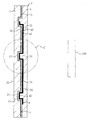
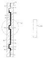
本発明による実施形態の車載レーダー装置用レドーム1では、図1~図4に示すように、透明で電磁波透過性の前基材2と、加飾層3と、ヒーター層4と、電磁波透過性の後基材5が表面側から順に密接するように固着して設けられている。図示例の前基材2は正面視で楕円形であり、この透明の前基材2を介して、表面側から意匠部を構成するマーク記号部10を視認可能になっている。図1中のRは電磁波透過領域である。尚、前基材2やレドーム1の形状は楕円形以外にも適用可能な範囲で任意であり、例えば、正方形、長方形、台形、真円形、三角形といった形状でもよい. [Radome for in-vehicle radar device of the first embodiment]
In theradome 1 for an in-vehicle radar device according to the present invention, as shown in FIGS. 1 to 4, a transparent and electromagnetic wave transmitting front base material 2, a decorative layer 3, a heater layer 4, and an electromagnetic wave transmitting property are used. The rear base material 5 is fixedly provided so as to be in close contact with each other in order from the surface side. The front base material 2 in the illustrated example has an elliptical shape when viewed from the front, and the mark symbol portion 10 constituting the design portion can be visually recognized from the surface side through the transparent front base material 2. R in FIG. 1 is an electromagnetic wave transmission region. The shapes of the front base material 2 and the radome 1 are arbitrary as long as they can be applied in addition to the elliptical shape, and may be, for example, a square, a rectangle, a trapezoid, a perfect circle, or a triangle.
本発明による実施形態の車載レーダー装置用レドーム1では、図1~図4に示すように、透明で電磁波透過性の前基材2と、加飾層3と、ヒーター層4と、電磁波透過性の後基材5が表面側から順に密接するように固着して設けられている。図示例の前基材2は正面視で楕円形であり、この透明の前基材2を介して、表面側から意匠部を構成するマーク記号部10を視認可能になっている。図1中のRは電磁波透過領域である。尚、前基材2やレドーム1の形状は楕円形以外にも適用可能な範囲で任意であり、例えば、正方形、長方形、台形、真円形、三角形といった形状でもよい. [Radome for in-vehicle radar device of the first embodiment]
In the
透明な前基材2と、後基材5は絶縁性で電磁波透過性を有する。前基材2と、後基材5には、例えば同一材料で形成する等、複素誘電率に基づき定義される屈折率nが相互に整合する、又は、屈折率nが略同一或いは近接するものを用いると電磁波の透過性能向上の観点から好適である。前基材2と後基材5の近接する屈折率nの数値範囲としては、前基材2と後基材5の屈折率の相違が0~10%の範囲内とすると良好である。
The transparent front base material 2 and the back base material 5 are insulating and have electromagnetic wave transmission. The refractive index n defined based on the complex permittivity is consistent with each other, or the refractive index n is substantially the same or close to each other, for example, the front base material 2 and the back base material 5 are formed of the same material. Is suitable from the viewpoint of improving the transmission performance of electromagnetic waves. As for the numerical range of the refractive indexes n close to each other between the front base material 2 and the rear base material 5, it is preferable that the difference in the refractive indexes between the front base material 2 and the rear base material 5 is within the range of 0 to 10%.
ここでの屈折率nは比誘電率実数部εr'と比誘電率虚数部εr"から数式1として定義される量である。 透過性の観点から適用周波数における虚数部と実数部の比から数式2として定義される誘電正接(ロスタンジェント)tanδの大きさは0.1以下とすると好適である。また比誘電率実部の大きさは3以下とすると好適である。誘電正接と非誘電率実部の大きさをこれらの数値以下とすることにより、レドームに必要とされる反射率と内部損失の低減を確実にすることが可能となる。
The refractive index n here is a quantity defined as Equation 1 from the relative permittivity real part εr'and the relative permittivity imaginary part εr ". From the viewpoint of transparency, the equation is based on the ratio of the imaginary part and the real part at the applicable frequency. It is preferable that the size of the dielectric tangent tan δ defined as 2 is 0.1 or less, and the size of the real part of the relative permittivity is 3 or less. Dielectric tangent and non-dielectric constant By making the size of the real part smaller than these values, it is possible to ensure the reduction of the reflectance and the internal loss required for the redome.


前基材2と、後基材5は、合成樹脂、ガラス、セラミックス等の本発明の趣旨の範囲内で適宜の材料を用いることが可能であるが、好適には絶縁性の合成樹脂とするとよい。透明の前基材2は、良好な視認性を確保するため可視光線透過率50%以上の無色材料又は有色材料とすることが好ましい。
As the front base material 2 and the back base material 5, appropriate materials such as synthetic resin, glass, and ceramics can be used within the scope of the present invention, but it is preferable to use an insulating synthetic resin. Good. The transparent front base material 2 is preferably a colorless material or a colored material having a visible light transmittance of 50% or more in order to ensure good visibility.
前基材2を絶縁性の透明合成樹脂とする場合の材料は、適用可能な範囲で適宜であり、例えばポリカーボネート(PC)、ポリメチルメタクリレート(PMMA)等のアクリル系樹脂、アクリロニトリル-ブタジエン-スチレン共重合体(ABS)、ポリエチレンテレフタレート(PET)、ポリエチレン(PE)、ポリプロピレン(PP)、アクリロニトリル-スチレン共重合体(AS)、ポリスチレン(PS)、シクロオレフィンポリマー(COP)等の1種を単独でまたは2種以上を組み合わせて用いることができ、又、添加剤を含有させてもよい。
When the pre-base material 2 is an insulating transparent synthetic resin, the material is appropriate to the extent applicable, and is, for example, an acrylic resin such as polypropylene (PC) or polymethylmethacrylate (PMMA), or acrylonitrile-butadiene-styrene. A single type of copolymer (ABS), polyethylene terephthalate (PET), polyethylene (PE), polypropylene (PP), acrylic nitrile-styrene copolymer (AS), polystyrene (PS), cycloolefin polymer (COP), etc. It can be used in combination with or in combination of two or more, and may contain an additive.
後基材5を絶縁性の合成樹脂とする場合の材料は、適用可能な範囲で適宜であり、例えばアクリロニトリル-エチレンプロピルラバー-スチレン共重合体(AES)、ポリメチルメタクリレート(PMMA)等のアクリル系樹脂、ポリカーボネート(PC)、アクリロニトリル-ブタジエン-スチレン共重合体(ABS)、アクリロニトリル-スチレン-アクリレート共重合(ASA)等の1種を単独でまたは2種以上を組み合わせて用いることができ、又、添加剤を含有させてもよい。
When the back base material 5 is an insulating synthetic resin, the material is appropriate to the extent applicable, and for example, acrylics such as acrylonitrile-ethylenepropyl rubber-styrene copolymer (AES) and polymethylmethacrylate (PMMA). One type of resin, polycarbonate (PC), acryliconitrile-butadiene-styrene copolymer (ABS), acryliconitrile-styrene-acrylate copolymer (ASA), etc. can be used alone or in combination of two or more. , Additives may be included.
前基材2の背面21には、加飾層3が密着して設けられており、本実施形態の加飾層3は、電磁波透過性金属部31と有色部32とから構成されている。尚、加飾層3は、本発明の趣旨の範囲内で適宜であり、電磁波透過性金属部31と有色部32で構成される加飾層3以外にも、例えば電磁波透過性金属部だけで構成される加飾層、或いは有色部だけで構成される加飾層等とすることが可能である。
A decorative layer 3 is provided in close contact with the back surface 21 of the front base material 2, and the decorative layer 3 of the present embodiment is composed of an electromagnetic wave transmitting metal portion 31 and a colored portion 32. The decorative layer 3 is appropriate within the scope of the gist of the present invention, and other than the decorative layer 3 composed of the electromagnetic wave transmitting metal portion 31 and the colored portion 32, for example, only the electromagnetic wave transmitting metal portion is used. It can be a decorative layer composed of a colored portion, a decorative layer composed of only a colored portion, or the like.
電磁波透過性金属部31は、電磁波透過性で金属光沢を有する不連続金属層で構成され、光輝性で一体的な視認性を有し、前基材2の背面21に無電解めっき、蒸着又はスパッタ等で形成されている。電磁波透過性金属部31を光輝性で一体的な視認性を有する不連続金属層とする場合、例えばニッケル若しくはニッケル合金、クロム若しくはクロム合金、コバルト若しくはコバルト合金、錫若しくは錫合金、銅若しくは銅合金、銀若しくは銀合金、パラジウム若しくはパラジウム合金、白金若しくは白金合金、ロジウム若しくはロジウム合金、金若しくは金合金等から構成することが可能である。
The electromagnetic wave transmitting metal portion 31 is composed of a discontinuous metal layer having electromagnetic wave transmission and metallic luster, has brilliant and integrated visibility, and is electroless plated, vapor-deposited, or deposited on the back surface 21 of the front base material 2. It is formed by spatter or the like. When the electromagnetic wave transmitting metal portion 31 is a discontinuous metal layer having a brilliant and integrated visibility, for example, nickel or nickel alloy, chromium or chromium alloy, cobalt or cobalt alloy, tin or tin alloy, copper or copper alloy. , Silver or silver alloy, palladium or palladium alloy, platinum or platinum alloy, rhodium or rhodium alloy, gold or gold alloy and the like.
尚、電磁波透過性金属部31は、電磁波透過性で金属光沢と一体的な視認性を有する不連続金属層以外にも、本発明の趣旨の範囲内で適宜の電磁波透過性金属部とすることが可能であり、例えば蒸着又はスパッタ等で形成されたシリコンやゲルマニウム等の半導体層、或いはこの半導体と可視光反射率が50%以上の金属(例えば金、銀、銅、アルミニウム、白金、パラジウム、鉄、ニッケル、クロム)等の光輝金属との合金層等とすることが可能である。また、前基材2の背面21と電磁波透過性金属部31との間には、例えば無電解めっき層を形成しやすくする改質表面を形成するための下地層など、必要に応じて透明下地層等の下地層を設けることも可能である。
In addition to the discontinuous metal layer that is electromagnetically permeable and has visibility integrated with metallic luster, the electromagnetic wave transmitting metal portion 31 shall be an appropriate electromagnetic wave transmitting metal portion within the scope of the present invention. Is possible, for example, a semiconductor layer such as silicon or germanium formed by vapor deposition or sputtering, or a metal having a visible light reflectance of 50% or more (for example, gold, silver, copper, aluminum, platinum, palladium, etc.). It can be an alloy layer with a bright metal such as iron, nickel, or chromium). Further, between the back surface 21 of the front base material 2 and the electromagnetic wave transmitting metal portion 31, for example, a base layer for forming a modified surface that facilitates the formation of an electroless plating layer, or the like, if necessary, is transparent. It is also possible to provide a base layer such as a stratum.
有色部32は、電磁波透過性を有し、印刷、又は塗装マスクを用いた塗装等で形成されている。本実施形態の加飾層3では、有色部32が電磁波透過性金属部31の表面側の一部に積層されるようにして前基材2の背面21に密着して設けられており、前基材2の背面21が露出している領域と、有色部32が設けられている領域の全体に亘って電磁波透過性金属部31が層状に形成され、前基材2の露出した背面21と有色部32に密着して設けられている。
The colored portion 32 has electromagnetic wave transmission and is formed by printing, painting with a painting mask, or the like. In the decorative layer 3 of the present embodiment, the colored portion 32 is provided in close contact with the back surface 21 of the front base material 2 so as to be laminated on a part of the surface side of the electromagnetic wave transmitting metal portion 31. The electromagnetic wave transmitting metal portion 31 is formed in a layer over the entire region where the back surface 21 of the base material 2 is exposed and the region where the colored portion 32 is provided, and the back surface 21 of the front base material 2 is exposed. It is provided in close contact with the colored portion 32.
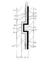
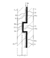
そして、前基材2の背面21側には、マーク記号部10に対応する位置に第1の凹部211が形成されており、加飾層3は、第1の凹部211に倣うように断面視で表面側に部分突出して曲がって形成されている。図示例では、加飾層3の電磁波透過性金属部31が第1の凹部211に倣うように部分突出して形成され、第1の凹部211には有色部32は設けられず、電磁波透過性金属部31だけが入り込んで設けられている。また、図示例の有色部32は、前基材2の第1の凹部211以外の背面21に沿うように密着して設けられている。
A first recess 211 is formed on the back surface 21 side of the front base material 2 at a position corresponding to the mark symbol portion 10, and the decorative layer 3 is viewed in cross section so as to imitate the first recess 211. It is formed by partially protruding toward the surface and bending. In the illustrated example, the electromagnetic wave transmitting metal portion 31 of the decorative layer 3 is formed so as to partially project so as to imitate the first recess 211, and the colored portion 32 is not provided in the first recess 211, and the electromagnetic wave transmitting metal Only the part 31 is inserted and provided. Further, the colored portion 32 of the illustrated example is provided in close contact with the back surface 21 other than the first recess 211 of the front base material 2.
加飾層3の背面33側には、第1の凹部211に対応する位置に第2の凹部34が設けられており、ヒーター層4は、第2の凹部34に倣うように断面視で表面側に部分突出して曲がって形成され、突出部43が第2の凹部34に係合されるようにして配置されている。ヒーター層4は、ヒーターエレメント41を有し、絶縁フィルム42と、絶縁フィルム42の背面側に固着されたヒーターエレメント41から構成される。
A second recess 34 is provided on the back surface 33 side of the decorative layer 3 at a position corresponding to the first recess 211, and the heater layer 4 has a surface view in cross section so as to imitate the second recess 34. It is formed so as to be partially projected to the side and bent, and the protruding portion 43 is arranged so as to be engaged with the second recess 34. The heater layer 4 has a heater element 41, and is composed of an insulating film 42 and a heater element 41 fixed to the back surface side of the insulating film 42.
ヒーターエレメント41は、例えばニクロム線、鉄クロム、銅、銀、カーボン繊維、ITO膜のような透明導電膜等の適用可能な適宜の導電性材料とすることが可能である。尚、例えばヒーターエレメント42を40℃~50℃まで昇温した場合、加飾層3の耐熱温度は例えば100℃程度、PC等の前基材2の耐熱温度は例えば80℃程度、AES等の後基材5の耐熱温度は例えば80℃程度であることから、ヒーターエレメント42の昇温に対して良好な耐熱性のある構造になっている。
The heater element 41 can be made of an appropriate conductive material such as nichrome wire, iron chromium, copper, silver, carbon fiber, and a transparent conductive film such as an ITO film. For example, when the heater element 42 is heated to 40 ° C. to 50 ° C., the heat resistant temperature of the decorative layer 3 is, for example, about 100 ° C., the heat resistant temperature of the front base material 2 such as PC is, for example, about 80 ° C., AES or the like. Since the heat-resistant temperature of the rear substrate 5 is, for example, about 80 ° C., the structure has good heat resistance to the temperature rise of the heater element 42.
絶縁フィルム42は、適用可能な適宜の電磁波透過性を有する絶縁性素材とすることが可能であり、例えばポリカーボネート(PC)、ポリエチレン(PE)、ポリプロピレン(PP、OPP)、ポリエチレンテレフタレート(PET)、ポリエチレンナフタレート(PEN)、塩化ビニル(PVC)、ポリスチレン(PS)、アクリル(AC)、又はポリエーテルエーテルケトン(PEEK)等の絶縁性合成樹脂で形成すると好適である。また、絶縁フィルム42の厚さは、前基材2への熱伝導性を高め、ヒーターエレメント41を保護する観点から0.05~1.0mmとすると好適である。
The insulating film 42 can be an insulating material having an appropriate electromagnetic wave transmittance applicable, and for example, polycarbonate (PC), polyethylene (PE), polypropylene (PP, OPP), polyethylene terephthalate (PET), and the like. It is preferably formed of an insulating synthetic resin such as polyethylene naphthalate (PEN), vinyl chloride (PVC), polystyrene (PS), acrylic (AC), or polyetheretherketone (PEEK). Further, the thickness of the insulating film 42 is preferably 0.05 to 1.0 mm from the viewpoint of increasing the thermal conductivity to the front base material 2 and protecting the heater element 41.
絶縁フィルム42には、前基材2及び後基材5と、複素誘電率に基づき定義される屈折率nが相互に整合する、又は、屈折率nが略同一或いは近接するものを用いると電磁波の透過性能向上の観点から好適である。前基材2及び後基材5と絶縁フィルム42の近接する屈折率nの数値範囲としては、前基材2及び後基材5の屈折率と絶縁フィルム42の屈折率との相違が0~10%の範囲内となるようにすると良好である。尚、屈折率nも比誘電率実数部εr'と比誘電率虚数部εr"から数式1として定義される量である。また、絶縁フィルム42においても、透過性の観点から適用周波数における虚数部と実数部の比から数式2として定義される誘電正接(ロスタンジェント)tanδの大きさを0.1以下とすることが好ましい。
When the insulating film 42 has a refractive index n defined based on the complex permittivity of the front base material 2 and the rear base material 5 that are mutually matched, or have substantially the same or close refractive index n, electromagnetic waves are used. It is suitable from the viewpoint of improving the permeation performance of the film. As for the numerical range of the refractive index n close to the front base material 2 and the back base material 5 and the insulating film 42, the difference between the refractive index of the front base material 2 and the rear base material 5 and the refractive index of the insulating film 42 is 0 to 0 to It is good to keep it within the range of 10%. The refractive index n is also a quantity defined as Equation 1 from the relative permittivity real part εr'and the relative permittivity imaginary part εr'. Further, also in the insulating film 42, the imaginary part at the applicable frequency from the viewpoint of transparency. It is preferable that the magnitude of the dielectric constant tangent tan δ defined as Equation 2 from the ratio of the real number part to 0.1 is 0.1 or less.
ヒーター層4のヒーターエレメント41は、その両端がコネクタ6に電気的に接続され且つ機械的に固定されており、コネクタ6を介してヒーターエレメント41に電力が供給され、ヒーターエレメント41が発熱するようになっている。更に、本実施形態におけるコネクタ6から延びるヒーターエレメント41は、前基材2の背面21の面方向に蛇行して折り返すように配線されて一連で延びて形成されており、ヒーター層4で隣り合って配線されているヒーターエレメント41・41に流れる電流の方向が互いに略反平行或いは反平行となるように設定されている。また、加飾層3の第2の凹部34における前基材2の面方向に離間する複数箇所にヒーターエレメント41が配設され、第2の凹部34の複数箇所のヒーターエレメント41でエンブレムの意匠部の周辺を確実に融雪して視認性をより高めることができるようになっている。
Both ends of the heater element 41 of the heater layer 4 are electrically connected to the connector 6 and mechanically fixed, and power is supplied to the heater element 41 via the connector 6 so that the heater element 41 generates heat. It has become. Further, the heater element 41 extending from the connector 6 in the present embodiment is formed by wiring so as to meander and fold back in the surface direction of the back surface 21 of the front base material 2 and extend in a series, and is adjacent to each other by the heater layer 4. The directions of the currents flowing through the heater elements 41 and 41 that are wired to each other are set to be substantially antiparallel or antiparallel to each other. Further, heater elements 41 are arranged at a plurality of locations in the second recess 34 of the decorative layer 3 which are separated from each other in the surface direction of the front base material 2, and the heater elements 41 at the plurality of locations of the second recess 34 design the emblem. It is possible to surely melt the snow around the part and improve the visibility.
更に、よりバランス良く熱拡散の均一性の向上と熱伝導効率の向上を図り、前基材2の表面全体に亘って均一性の高い確実な融雪を行う観点からは、前基材2の表面22から第1の凹部211の表面側に位置する底までの距離L1を0.1~10mmに設定すると良好であり、より好ましくは0.7mm~8mm、より一層好ましくは1.5mm~4.5mmに設定するとよい。同様の観点から、ヒーター層4の部分突出する突出部43の先端からヒーター層4の突出部43以外の最背面44までの距離L2を1~10mmに設定すると良好であり、1.5mm~4.5mmに設定するとより好ましい。
Further, from the viewpoint of improving the uniformity of heat diffusion and improving the heat conduction efficiency in a more balanced manner and performing reliable snow melting with high uniformity over the entire surface of the front base material 2, the surface of the front base material 2 is used. It is preferable to set the distance L1 from 22 to the bottom located on the surface side of the first recess 211 to 0.1 to 10 mm, more preferably 0.7 mm to 8 mm, and even more preferably 1.5 mm to 4. It is recommended to set it to 5 mm. From the same viewpoint, it is good to set the distance L2 from the tip of the partially protruding protrusion 43 of the heater layer 4 to the rearmost surface 44 other than the protruding portion 43 of the heater layer 4 to 1 to 10 mm, and 1.5 mm to 4 It is more preferable to set it to 5.5 mm.
そして、車載レーダー装置用レドーム1では、加飾層3の第2の凹部34に対応する位置に設けられるヒーター層4の背面側の第3の凹部45に、換言すれば突出部43の裏面側に、凸部51を係合するようにして、ヒーター層4の背面側に電磁波透過性の後基材5が設けられている。この車載レーダー装置用レドーム1は、車載レーダー装置100の前方に配置されて車両に取り付けられる。尚、図示例の車載レーダー装置用レドーム1はエンブレム形状のレドームとしたが、本発明の車載レーダー装置用レドームは、バンパー等の適宜の車両実装部品で構成することが可能である。
Then, in the radome 1 for an in-vehicle radar device, the third recess 45 on the back side of the heater layer 4 provided at a position corresponding to the second recess 34 of the decorative layer 3, in other words, the back side of the protrusion 43. A rear base material 5 for electromagnetic wave transmission is provided on the back surface side of the heater layer 4 so as to engage the convex portion 51. The radome 1 for the vehicle-mounted radar device is arranged in front of the vehicle-mounted radar device 100 and attached to the vehicle. Although the radome 1 for an in-vehicle radar device in the illustrated example is an emblem-shaped radome, the radome for an in-vehicle radar device of the present invention can be configured by an appropriate vehicle-mounted component such as a bumper.
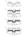
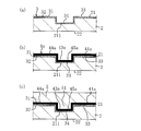
第1実施形態の車載レーダー装置用レドーム1を製造する際には、例えば図5に示す第1例では、電磁波透過性の前基材2の背面21側の第1の凹部211に倣うように表面側に部分突出するように加飾層3を形成する。加飾層3の形成工程では、例えば有色部32を、印刷、又は塗装マスクを用いた塗装等により、前基材2の背面21の所定領域に形成した後、無電解めっき、蒸着又はスパッタ等により、前基材2の背面21の第1の凹部211内を含む全体に亘って電磁波透過性金属部31を形成する(図5(a)参照)。
When manufacturing the radome 1 for an in-vehicle radar device of the first embodiment, for example, in the first example shown in FIG. 5, the first recess 211 on the back surface 21 side of the electromagnetic wave transmitting front base material 2 is imitated. The decorative layer 3 is formed so as to partially project toward the surface side. In the process of forming the decorative layer 3, for example, the colored portion 32 is formed in a predetermined area on the back surface 21 of the front base material 2 by printing or painting with a coating mask, and then electroless plating, vapor deposition, sputtering, or the like. As a result, the electromagnetic wave transmitting metal portion 31 is formed over the entire surface including the inside of the first recess 211 on the back surface 21 of the front base material 2 (see FIG. 5A).
次いで、絶縁フィルム42と絶縁フィルム42の背面側に固着されたヒーターエレメント41から構成され、所定領域に突出部43が予め形成されている3次元形状のシート状のヒーター層4を用い、第1の凹部211に対応する位置に設けられている加飾層3の背面側の第2の凹部34に、表面側に部分突出し且つ第2の凹部34に倣う形状で形成されている突出部43を係合して、ヒーター層4を加飾層3に固着する(図5(b)、(c)参照)。このヒーター層4の加飾層3への固着は、熱溶着又は接着剤による接着で行うと良好である。また、予め突出部43が形成されたヒーター層4において、絶縁フィルム42へのヒーターエレメント41の形成或いは描画は、例えば印刷、蒸着、スパッタ、めっき、エッチング、MID、ワイヤーボンディング、インクジェット、又はディスペンサー等を用いて行うことが可能である。
Next, a three-dimensional sheet-shaped heater layer 4 composed of an insulating film 42 and a heater element 41 fixed to the back surface side of the insulating film 42 and having a protruding portion 43 formed in advance in a predetermined region is used. In the second concave portion 34 on the back surface side of the decorative layer 3 provided at a position corresponding to the concave portion 211 of the above, a protruding portion 43 that partially protrudes toward the front surface side and is formed in a shape that imitates the second concave portion 34. Engage and fix the heater layer 4 to the decorative layer 3 (see FIGS. 5 (b) and 5 (c)). The adhesion of the heater layer 4 to the decorative layer 3 is preferably performed by heat welding or adhesion with an adhesive. Further, in the heater layer 4 in which the protruding portion 43 is formed in advance, the formation or drawing of the heater element 41 on the insulating film 42 may be performed by, for example, printing, vapor deposition, sputtering, plating, etching, MID, wire bonding, inkjet, dispenser, or the like. It is possible to do this using.
その後、加飾層3が形成され且つヒーター層4が設けられた前基材2を金型内に配置し、加飾層3の第2の凹部34に対応する位置に設けられているヒーター層4の背面側の第3の凹部45に凸部51が係合されるようにして、ヒーター層4の背面側に電磁波透過性の後基材5を射出成形で形成し、車載レーダー装置用レドーム1を得る(図5(d)参照)。
After that, the front base material 2 on which the decorative layer 3 is formed and the heater layer 4 is provided is arranged in the mold, and the heater layer is provided at a position corresponding to the second recess 34 of the decorative layer 3. A radome for an in-vehicle radar device is formed by injection molding on the back surface side of the heater layer 4 so that the convex portion 51 is engaged with the third concave portion 45 on the back surface side of the fourth. 1 is obtained (see FIG. 5 (d)).
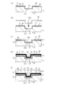
また、第1実施形態の車載レーダー装置用レドーム1の製造工程の別例(第2例)として、図6(a)に示すように、上記第1例と同様、電磁波透過性の前基材2の背面21側の第1の凹部211に倣うように表面側に部分突出するように加飾層3を形成した後、所定領域に突出部43mが予め形成されている3次元形状のシート状の絶縁フィルム42を用い、第1の凹部211に対応する位置に設けられている加飾層3の背面側の第2の凹部34に、表面側に部分突出し且つ第2の凹部34に倣う形状で形成されている突出部43mを係合して、絶縁フィルム42を加飾層3に固着する(図6(b)、(c)参照)。この絶縁フィルム42の加飾層3への固着は、熱溶着又は接着剤による接着で行うと良好である。
Further, as another example (second example) of the manufacturing process of the radome 1 for the in-vehicle radar device of the first embodiment, as shown in FIG. 6A, as in the first example, the electromagnetic wave transmitting front base material. After forming the decorative layer 3 so as to partially project toward the front surface so as to follow the first recess 211 on the back surface 21 side of 2, a three-dimensional sheet shape in which a projecting portion 43 m is previously formed in a predetermined area. Insulating film 42 of the above, a shape that partially protrudes toward the surface side and follows the second recess 34 in the second recess 34 on the back surface side of the decorative layer 3 provided at a position corresponding to the first recess 211. The insulating film 42 is fixed to the decorative layer 3 by engaging the projecting portion 43 m formed in (see FIGS. 6 (b) and 6 (c)). Adhesion of the insulating film 42 to the decorative layer 3 is preferably performed by heat welding or adhesion with an adhesive.
その後、図6(d)に示すように、絶縁フィルム42の背面側にヒーターエレメント41を形成して固着し、絶縁フィルム42と絶縁フィルム42の背面側に固着されたヒーターエレメント41から構成されるヒーター層4を形成する。この工程における絶縁フィルム42へのヒーターエレメント41の形成或いは描画も、例えば印刷、蒸着、スパッタ、メッキ、エッチング、ワイヤーボンディング、インクジェット、又はディスペンサー等を用いて行うことが可能である。
After that, as shown in FIG. 6D, the heater element 41 is formed and fixed to the back side of the insulating film 42, and is composed of the insulating film 42 and the heater element 41 fixed to the back side of the insulating film 42. The heater layer 4 is formed. The formation or drawing of the heater element 41 on the insulating film 42 in this step can also be performed by using, for example, printing, vapor deposition, sputtering, plating, etching, wire bonding, an inkjet, or a dispenser.
その後、加飾層3が形成され且つヒーター層4が設けられた前基材2を金型内に配置し、加飾層3の第2の凹部34に対応する位置に設けられているヒーター層4の背面側の第3の凹部45に凸部51が係合されるようにして、ヒーター層4の背面側に電磁波透過性の後基材5を射出成形で形成し、車載レーダー装置用レドーム1を得る(図6(e)参照)。
After that, the front base material 2 on which the decorative layer 3 is formed and the heater layer 4 is provided is arranged in the mold, and the heater layer is provided at a position corresponding to the second recess 34 of the decorative layer 3. A radome for an in-vehicle radar device is formed by injection molding on the back surface side of the heater layer 4 so that the convex portion 51 is engaged with the third concave portion 45 on the back surface side of the fourth. 1 is obtained (see FIG. 6 (e)).
第1実施形態によれば、ヒーター層4の表面側に加飾層3が設けられることにより、透明な前基材2を介して、エンブレムの意匠部等を構成する加飾層3の良好な視認性を確保することができる。また、加飾層3とヒーター層4との間に空隙部や基材が設けられずに、加飾層3とヒーター層4が密接して設けられるため、電磁波透過性を向上することができる。また、透明な前基材2の表面22とヒーター層4との間に、別の基材が設けられずに、前基材2と加飾層3が設けられることから、ヒーター層4から前基材2の表面22への熱伝導効率を高めることができ、レドーム1の外表面に付着した雪や氷を確実に融雪することができる。また、第1の凹部211、第2の凹部34に対応する位置では、ヒーター層4が表面側に部分突出することにより、前基材2の表面22の単位面積当たりの占有面積を増やさずにヒーター層4或いはそのヒーターエレメント41の密度を高めることが可能となる。或いは従来と同等の融雪を細い線幅のヒーターエレメント41で行うことも可能である。これにより、確実な融雪を行いつつ、電磁波透過性を一層向上することができる。また、前基材2の表面22とヒーター層4との間には前基材2が設置されていることから、前基材2の厚みや広がりでヒーター層4の加熱を熱拡散して、前基材2の表面22の全体に亘って均一性の高い融雪を行うことができる。また、加飾層3とヒーター層4との間に基材を設けない構成であることから、この間の基材の成形工程を無くすことができ、より高い製造効率で製造することができる。
According to the first embodiment, by providing the decorative layer 3 on the surface side of the heater layer 4, the decorative layer 3 constituting the design portion of the emblem or the like is good via the transparent front base material 2. Visibility can be ensured. Further, since the decorative layer 3 and the heater layer 4 are provided in close contact with each other without providing a gap or a base material between the decorative layer 3 and the heater layer 4, electromagnetic wave transmission can be improved. .. Further, since the front base material 2 and the decorative layer 3 are provided between the surface 22 of the transparent front base material 2 and the heater layer 4 without providing another base material, the front base material 2 is provided in front of the heater layer 4. The efficiency of heat conduction to the surface 22 of the base material 2 can be increased, and the snow and ice adhering to the outer surface of the radome 1 can be reliably melted. Further, at the positions corresponding to the first recess 211 and the second recess 34, the heater layer 4 partially protrudes toward the surface side, so that the occupied area of the surface 22 of the front base material 2 per unit area is not increased. It is possible to increase the density of the heater layer 4 or the heater element 41 thereof. Alternatively, it is also possible to perform the same snow melting as before with the heater element 41 having a narrow line width. As a result, it is possible to further improve the electromagnetic wave transmission while surely melting the snow. Further, since the front base material 2 is installed between the surface 22 of the front base material 2 and the heater layer 4, the heating of the heater layer 4 is thermally diffused by the thickness and spread of the front base material 2. Highly uniform snow melting can be performed over the entire surface 22 of the front base material 2. Further, since the base material is not provided between the decorative layer 3 and the heater layer 4, the molding process of the base material during this period can be eliminated, and the production can be performed with higher production efficiency.
また、ヒーター層4の背面側の第3の凹部45に後基材5の凸部51を係合してヒーター層4の背面側に後基材5を設けることにより、後基材5の凸部51とヒーター層4の第3の凹部45を係合固着してより高い強度で固定することができる。
Further, by engaging the convex portion 51 of the rear base material 5 with the third concave portion 45 on the back surface side of the heater layer 4 and providing the rear base material 5 on the back surface side of the heater layer 4, the convex portion of the rear base material 5 is provided. The portion 51 and the third recess 45 of the heater layer 4 can be engaged and fixed to be fixed with higher strength.
また、隣り合って配置されるヒーターエレメント41・41に流れる電流の方向が互いに略反平行のなるようにすることで、隣り合うヒーターエレメント41・41から放射される電磁波を逆位相とし、ヒーターエレメント41からの電磁放射を打ち消すことができ、より優れた電磁波透過性能を得ることができる。特に、電磁波透過領域R等で、隣り合って配線されている各々のヒーターエレメント41・41に流れる電流の方向を互いに略反平行にすることにより、全体に亘って非常に優れた電磁波透過性能を発揮することができる。
Further, by making the directions of the currents flowing through the heater elements 41 and 41 arranged adjacent to each other substantially antiparallel to each other, the electromagnetic waves radiated from the adjacent heater elements 41 and 41 have opposite phases, and the heater elements The electromagnetic radiation from 41 can be canceled, and better electromagnetic wave transmission performance can be obtained. In particular, in the electromagnetic wave transmission region R or the like, by making the directions of the currents flowing through the heater elements 41 and 41, which are wired adjacent to each other, substantially antiparallel to each other, extremely excellent electromagnetic wave transmission performance can be obtained as a whole. Can be demonstrated.
また、ヒーター層4を絶縁フィルム42と絶縁フィルム42の背面側に固着されたヒーターエレメント41から構成することにより、絶縁フィルム42による絶縁性担保により、電磁波透過性金属部31を有する加飾層3など加飾層の構成に拘わらず、ヒーターエレメント41への通電で加飾層3に導通が発生することを防止でき、加飾層3の導通で電磁波透過性が低下することを確実に防止できる。また、絶縁フィルム42にヒーターエレメント41を固着することにより、ヒーターエレメント41の位置ズレを防止できると共に、絶縁フィルム42でヒーターエレメント41を保護することもできる。また、絶縁フィルム42はヒーターエレメント41を固着する下地として機能し、ヒーターエレメント41の加飾層3への固着強度を高めることができる。
Further, by forming the heater layer 4 from the insulating film 42 and the heater element 41 fixed to the back surface side of the insulating film 42, the decorative layer 3 having the electromagnetic wave transmitting metal portion 31 is ensured by the insulating film 42. Regardless of the configuration of the decorative layer, it is possible to prevent the decorative layer 3 from being electrically connected by energizing the heater element 41, and it is possible to reliably prevent the electromagnetic wave transmission from being lowered by the conduction of the decorative layer 3. .. Further, by fixing the heater element 41 to the insulating film 42, the position of the heater element 41 can be prevented from being displaced, and the heater element 41 can be protected by the insulating film 42. Further, the insulating film 42 functions as a base for fixing the heater element 41, and can increase the fixing strength of the heater element 41 to the decorative layer 3.
また、第1例の車載レーダー装置用レドーム1の製造方法によれば、ヒーター層4の表面側に部分突出し且つ第2の凹部34に倣う形状の突出部43が形成され、絶縁フィルム42とその背面側に固着されたヒーターエレメント41から構成されるヒーター層4を用い、突出部43を第2の凹部34に係合してヒーター層4を固着することにより、容易に位置合わせしてヒーター層4の絶縁フィルム42とヒーターエレメント41を設けることができ、製造作業を容易化することができる。また、中間品のヒーター層4は、絶縁フィルム42だけを基にしてヒーターエレメント41を形成して得ることができることから、多様な製造手段を用いて形成することが可能となり、適用可能な製造手段の多様化を図ることができる。また、ヒーター層4の背面側の第3の凹部45に後基材5の凸部51を係合してヒーター層4の背面側に後基材5を射出成形することにより、後基材5の凸部51とヒーター層4の第3の凹部45を係合固着した高い固着強度の後基材5を背面側に設けることができる。
Further, according to the manufacturing method of the radome 1 for an in-vehicle radar device of the first example, a protruding portion 43 that partially protrudes on the surface side of the heater layer 4 and has a shape that imitates the second recess 34 is formed, and the insulating film 42 and its Using the heater layer 4 composed of the heater element 41 fixed to the back side, the protrusion 43 is engaged with the second recess 34 to fix the heater layer 4, so that the heater layer can be easily aligned. The insulating film 42 and the heater element 41 of No. 4 can be provided, and the manufacturing work can be facilitated. Further, since the heater layer 4 of the intermediate product can be obtained by forming the heater element 41 based only on the insulating film 42, it can be formed by using various manufacturing means, and the applicable manufacturing means. Can be diversified. Further, by engaging the convex portion 51 of the rear base material 5 with the third concave portion 45 on the back surface side of the heater layer 4 and injecting the rear base material 5 on the back surface side of the heater layer 4, the rear base material 5 is formed. A rear base material 5 having a high fixing strength in which the convex portion 51 of the heater layer 4 and the third concave portion 45 of the heater layer 4 are engaged and fixed can be provided on the back surface side.
また、第2例の車載レーダー装置用レドーム1の製造方法によれば、表面側に部分突出し且つ第2の凹部34に倣う形状の突出部43mが形成された絶縁フィルム42を用い、突出部43mを第2の凹部34に係合して絶縁フィルム42を固着することにより、容易に位置合わせして絶縁フィルム42を設けることができ、製造作業を容易化することができる。また、既に加飾層3に固着された絶縁フィルム42の背面側にヒーターエレメント41を形成することにより、ヒーターエレメント41をより正確な位置に安定して設置することができる。また、ヒーター層4の背面側の第3の凹部45に後基材5の凸部51を係合してヒーター層4の背面側に後基材5を射出成形することにより、後基材5の凸部51とヒーター層4の第3の凹部45を係合固着した高い固着強度の後基材5を背面側に設けることができる。
Further, according to the method of manufacturing the radome 1 for an in-vehicle radar device of the second example, the insulating film 42 having a partially protruding portion on the surface side and a protruding portion 43 m having a shape following the second recess 34 is used, and the protruding portion 43 m. Is engaged with the second recess 34 to fix the insulating film 42, so that the insulating film 42 can be easily aligned and the insulating film 42 can be provided, and the manufacturing work can be facilitated. Further, by forming the heater element 41 on the back surface side of the insulating film 42 already fixed to the decorative layer 3, the heater element 41 can be stably installed at a more accurate position. Further, by engaging the convex portion 51 of the rear base material 5 with the third concave portion 45 on the back surface side of the heater layer 4 and injecting the rear base material 5 on the back surface side of the heater layer 4, the rear base material 5 is formed. A rear base material 5 having a high fixing strength in which the convex portion 51 of the heater layer 4 and the third concave portion 45 of the heater layer 4 are engaged and fixed can be provided on the back surface side.
〔第2実施形態の車載レーダー装置用レドーム〕
本発明による実施形態の車載レーダー装置用レドーム1aでは、図7及び図8に示すように、透明で電磁波透過性の前基材2と、加飾層3と、ヒーター層4aと、電磁波透過性の後基材5が表面側から順に密接するように固着して設けられている。ヒーター層4aは、第1実施形態のヒーター層4とは異なり、ヒーターエレメント41aだけで構成されている。 [Radome for in-vehicle radar device of the second embodiment]
In the radome 1a for an in-vehicle radar device according to the present invention, as shown in FIGS. 7 and 8, a transparent and electromagnetic wave transmittingfront base material 2, a decorative layer 3, a heater layer 4a, and an electromagnetic wave transmitting property are used. The rear base material 5 is fixedly provided so as to be in close contact with each other in order from the surface side. Unlike the heater layer 4 of the first embodiment, the heater layer 4a is composed of only the heater element 41a.
本発明による実施形態の車載レーダー装置用レドーム1aでは、図7及び図8に示すように、透明で電磁波透過性の前基材2と、加飾層3と、ヒーター層4aと、電磁波透過性の後基材5が表面側から順に密接するように固着して設けられている。ヒーター層4aは、第1実施形態のヒーター層4とは異なり、ヒーターエレメント41aだけで構成されている。 [Radome for in-vehicle radar device of the second embodiment]
In the radome 1a for an in-vehicle radar device according to the present invention, as shown in FIGS. 7 and 8, a transparent and electromagnetic wave transmitting
ヒーターエレメント41aだけで構成されたヒーター層4aは、第1の凹部211に対応する位置に設けられた第2の凹部34に倣うように断面視で表面側に部分突出して曲がって形成され、突出部43aが第2の凹部34に係合されるようにして配置されている。ヒーターエレメント41aは第1実施形態のヒーターエレメント41と同様の材料で形成される。
The heater layer 4a composed of only the heater element 41a is formed by being partially projected toward the surface side in a cross-sectional view so as to follow the second recess 34 provided at a position corresponding to the first recess 211, and is formed to project. The portion 43a is arranged so as to be engaged with the second recess 34. The heater element 41a is made of the same material as the heater element 41 of the first embodiment.
ヒーターエレメント41aも、第1実施形態のヒーターエレメント41と同様に、その両端がコネクタ6に電気的に接続され且つ機械的に固定されており、コネクタ6を介してヒーターエレメント41aに電力が供給され、ヒーターエレメント41aが発熱するようになっている。更に、ヒーターエレメント41aは、前基材2の背面21の面方向に蛇行して折り返すように配線されて一連で延びて形成されており、ヒーター層4aで隣り合って配線されているヒーターエレメント41a・41aに流れる電流の方向が互いに略反平行或いは反平行となるように設定されている(図1参照)。また、加飾層3の第2の凹部34における前基材2の面方向に離間する複数箇所にヒーターエレメント41aが配設され、第2の凹部34の複数箇所のヒーターエレメント41aでエンブレムの意匠部の周辺を確実に融雪して視認性をより高めることができるようになっている。
Similar to the heater element 41 of the first embodiment, both ends of the heater element 41a are electrically connected to the connector 6 and mechanically fixed, and power is supplied to the heater element 41a via the connector 6. , The heater element 41a is designed to generate heat. Further, the heater element 41a is formed by wiring so as to meander and fold back in the surface direction of the back surface 21 of the front base material 2 and extend in a series, and the heater elements 41a are wired adjacent to each other in the heater layer 4a. The directions of the currents flowing through 41a are set to be substantially antiparallel or antiparallel to each other (see FIG. 1). Further, heater elements 41a are arranged at a plurality of locations in the second recess 34 of the decorative layer 3 which are separated from each other in the surface direction of the front base material 2, and the design of the emblem is provided by the heater elements 41a at the plurality of locations of the second recess 34. It is possible to surely melt the snow around the part and improve the visibility.
よりバランス良く熱拡散の均一性の向上と熱伝導効率の向上を図り、前基材2の表面全体に亘って均一性の高い確実な融雪を行う観点からは、前基材2の表面22から第1の凹部211の表面側に位置する底までの距離L1を0.1~10mmに設定すると良好であり、より好ましくは0.7mm~8mm、より一層好ましくは1.5mm~4.5mmに設定するとよい。同様の観点から、ヒーター層4aの部分突出する突出部43aの先端からヒーター層4aの突出部43a以外の最背面44aまでの距離L2を1~10mmに設定すると良好であり、1.5mm~4.5mmに設定するとより好ましい。
From the viewpoint of improving the uniformity of heat diffusion and heat conduction efficiency in a more balanced manner and performing reliable snow melting with high uniformity over the entire surface of the front base material 2, from the surface 22 of the front base material 2. It is preferable to set the distance L1 to the bottom located on the surface side of the first recess 211 to 0.1 to 10 mm, more preferably 0.7 mm to 8 mm, and even more preferably 1.5 mm to 4.5 mm. It is good to set. From the same viewpoint, it is preferable to set the distance L2 from the tip of the partially protruding protrusion 43a of the heater layer 4a to the rearmost surface 44a other than the protruding portion 43a of the heater layer 4a to 1 to 10 mm, and 1.5 mm to 4 It is more preferable to set it to 5.5 mm.
そして、車載レーダー装置用レドーム1aでは、加飾層3の第2の凹部34に対応する位置に設けられるヒーター層4aの背面側の第3の凹部45aに、換言すれば突出部43aの裏面側に、凸部51を係合すると共に、ヒーター層4a或いはヒーターエレメント41aが設けられていない箇所或いは一部だけに設けられている箇所の第2の凹部34に凸部51を係合するようにして、ヒーター層4aの背面側に電磁波透過性の後基材5が設けられている。この車載レーダー装置用レドーム1aも、車載レーダー装置100の前方に配置されて車両に取り付けられる。車載レーダー装置用レドーム1aの構成による本発明の車載レーダー装置用レドームも、エンブレム、バンパー等の適宜の車両実装部品で構成することが可能である。尚、第2実施形態の車載レーダー装置用レドーム1aのその他の構成は、第1実施形態の車載レーダー装置用レドーム1と同様である。
Then, in the radome 1a for an in-vehicle radar device, the third recess 45a on the back side of the heater layer 4a provided at a position corresponding to the second recess 34 of the decorative layer 3, in other words, the back side of the protruding portion 43a. In addition to engaging the convex portion 51, the convex portion 51 is engaged with the second concave portion 34 of the portion where the heater layer 4a or the heater element 41a is not provided or is provided only partially. A rear base material 5 that transmits electromagnetic waves is provided on the back surface side of the heater layer 4a. The radome 1a for the vehicle-mounted radar device is also arranged in front of the vehicle-mounted radar device 100 and attached to the vehicle. The radome for an in-vehicle radar device of the present invention having the configuration of the radome 1a for an in-vehicle radar device can also be composed of appropriate vehicle-mounted parts such as an emblem and a bumper. The other configurations of the radome 1a for the vehicle-mounted radar device of the second embodiment are the same as those of the radome 1 for the vehicle-mounted radar device of the first embodiment.
第2実施形態の車載レーダー装置用レドーム1を製造する際には、図9に示す例のように、電磁波透過性の前基材2の背面21側の第1の凹部211に倣うように表面側に部分突出するように加飾層3を形成する。加飾層3の形成工程は、第1実施形態の第1例、第2例と同様であり、例えば有色部32を、印刷、又は塗装マスクを用いた塗装等により、前基材2の背面21の所定領域に形成した後、無電解めっき、蒸着又はスパッタ等により、前基材2の背面21の第1の凹部211内を含む全体に亘って電磁波透過性金属部31を形成する(図9(a)参照)。
When manufacturing the radome 1 for an in-vehicle radar device of the second embodiment, as shown in the example shown in FIG. 9, the surface of the radome 1 for an in-vehicle radar device follows the first recess 211 on the back surface 21 side of the electromagnetic wave transmitting front base material 2. The decorative layer 3 is formed so as to partially project to the side. The step of forming the decorative layer 3 is the same as that of the first and second examples of the first embodiment. For example, the colored portion 32 is printed or painted with a painting mask on the back surface of the front base material 2. After forming in a predetermined region of 21, the electromagnetic wave transmitting metal portion 31 is formed over the entire surface including the inside of the first recess 211 on the back surface 21 of the front base material 2 by electroless plating, vapor deposition, sputtering, or the like (FIG. 9 (a)).
その後、第1の凹部211に対応する位置に設けられている加飾層3の背面側の第2の凹部34に、表面側に部分突出し且つ第2の凹部34に倣う形状で形成される突出部43aを係合するようにして、ヒーター層4aを構成するヒーターエレメント41aを加飾層3の背面に密着して形成する(図9(b)参照)。この工程における加飾層3へのヒーターエレメント41aの形成或いは描画は、例えば印刷、蒸着、スパッタ、メッキ、エッチング、ワイヤーボンディング、インクジェット、又はディスペンサー等を用いて行うことが可能である。
After that, a protrusion formed in a second recess 34 on the back surface side of the decorative layer 3 provided at a position corresponding to the first recess 211, is partially projected toward the front surface and follows the second recess 34. The heater element 41a constituting the heater layer 4a is formed in close contact with the back surface of the decorative layer 3 by engaging the portions 43a (see FIG. 9B). The formation or drawing of the heater element 41a on the decorative layer 3 in this step can be performed by using, for example, printing, vapor deposition, sputtering, plating, etching, wire bonding, an inkjet, or a dispenser.
その後、加飾層3が形成され且つヒーター層4aが設けられた前基材2を金型内に配置し、加飾層3の第2の凹部34に対応する位置に設けられているヒーター層4aの背面側の第3の凹部45aと、ヒーターエレメント41aが設けられていない箇所或いは一部だけに設けられている箇所の第2の凹部34に、凸部51が係合されるようにして、ヒーター層4aの背面側に電磁波透過性の後基材5を射出成形で形成し、車載レーダー装置用レドーム1aを得る(図9(c)参照)。
After that, the front base material 2 on which the decorative layer 3 is formed and the heater layer 4a is provided is arranged in the mold, and the heater layer is provided at a position corresponding to the second recess 34 of the decorative layer 3. The convex portion 51 is engaged with the third concave portion 45a on the back surface side of the 4a and the second concave portion 34 where the heater element 41a is not provided or is provided only partially. A rear base material 5 for electromagnetic wave transmission is formed on the back surface side of the heater layer 4a by injection molding to obtain a radome 1a for an in-vehicle radar device (see FIG. 9C).
第2実施形態によれば、第1実施形態と対応する構成から対応する効果を得ることができると共に、ヒーターエレメント41aを直接加飾層3に密接させ、ヒーター層4aから前基材2の表面22への熱伝導効率をより高めることができ、レドームの外表面に付着した雪や氷をより確実に融雪することができる。
According to the second embodiment, the corresponding effect can be obtained from the configuration corresponding to the first embodiment, and the heater element 41a is directly brought into close contact with the decorative layer 3, and the surface of the front base material 2 from the heater layer 4a. The efficiency of heat conduction to 22 can be further increased, and snow and ice adhering to the outer surface of the radome can be more reliably melted.
また、第2実施形態の製造例によれば、加飾層3の背面33に直接ヒーターエレメント41aを形成することにより、ヒーターエレメント41aを加飾層3の背面33のより正確な位置に安定して設置することができる。また、ヒーター層4aの背面側の第3の凹部45aと、ヒーターエレメント41aが設けられていない若しくは一部だけに設けられている第2の凹部34とに後基材5の凸部51を係合してヒーター層4aの背面側に後基材5を射出成形することにより、後基材5の凸部51と第3の凹部45a、第2の凹部24を係合固着した高い固着強度の後基材5を背面側に設けることができる。
Further, according to the manufacturing example of the second embodiment, by forming the heater element 41a directly on the back surface 33 of the decorative layer 3, the heater element 41a is stabilized at a more accurate position on the back surface 33 of the decorative layer 3. Can be installed. Further, the convex portion 51 of the rear base material 5 is engaged with the third concave portion 45a on the back surface side of the heater layer 4a and the second concave portion 34 in which the heater element 41a is not provided or is provided only partially. In addition, by injection molding the rear base material 5 on the back surface side of the heater layer 4a, the convex portion 51 of the rear base material 5, the third concave portion 45a, and the second concave portion 24 are engaged and fixed to each other to have a high fixing strength. The rear base material 5 can be provided on the back side.
〔本明細書開示発明の包含範囲〕
本明細書開示の発明は、発明として列記した各発明、実施形態の他に、適用可能な範囲で、これらの部分的な内容を本明細書開示の他の内容に変更して特定したもの、或いはこれらの内容に本明細書開示の他の内容を付加して特定したもの、或いはこれらの部分的な内容を部分的な作用効果が得られる限度で削除して上位概念化して特定したものを包含する。そして、本明細書開示の発明には下記変形例や追記した内容も含まれる。 [Scope of inclusion of the invention disclosed in the present specification]
The inventions disclosed in the present specification are specified by changing these partial contents to other contents disclosed in the present specification to the extent applicable, in addition to the inventions and embodiments listed as inventions. Alternatively, those specified by adding other contents disclosed in the present specification to these contents, or those specified by deleting these partial contents to the extent that a partial effect can be obtained and making them into a higher concept. Include. The invention disclosed in the present specification also includes the following modifications and additional contents.
例えば本発明の車載レーダー装置用レドームにおける前基材の背面側の第1の凹部、加飾層の背面側の第2の凹部、ヒーター層の背面側の第3の凹部の形状と数は適用可能な範囲で適宜であり、それぞれ溝状或いは椀状等の所要形状の凹部とし、単数又は複数設けることが可能である。また、前基材の背面側に、第1の凹部に相当しない凹部が設けられる構造も本発明に含まれる。
For example, the shapes and numbers of the first recess on the back side of the front base material, the second recess on the back side of the decorative layer, and the third recess on the back side of the heater layer in the radome for an in-vehicle radar device of the present invention are applicable. It is appropriate to the extent possible, and it is possible to provide one or more recesses having a required shape such as a groove shape or a bowl shape, respectively. The present invention also includes a structure in which a recess not corresponding to the first recess is provided on the back surface side of the front base material.
また、本発明の車載レーダー装置用レドームは、隣り合って配線されているヒーター線に流れる電流の方向が互いに略反平行或いは反平行である構成とすると好適であるが、隣り合って配線されているヒーター線に流れる電流の方向が互いに略反平行或いは反平行でない構成の場合も包含する。
Further, the radome for an in-vehicle radar device of the present invention is preferably configured such that the directions of currents flowing through the heater wires wired adjacent to each other are substantially antiparallel or antiparallel to each other, but they are wired adjacent to each other. It also includes the case where the directions of the currents flowing through the heater wires are substantially antiparallel or not antiparallel to each other.
また、本発明の車載レーダー装置用レドームが対象とするレーダーの電磁波は適用可能な範囲で適宜であり、車載レーダーとして実用化されている24/26GHz帯、76/77GHz帯、77/81GHz帯等に加え、これら以外のレーダー用の電磁波にも本発明を適用することが可能である。更に、より短波長のレーダーが実用化された際にも同様に本発明を適用することが可能である。
Further, the electromagnetic wave of the radar targeted by the radome for the in-vehicle radar device of the present invention is appropriate within an applicable range, and the 24/26 GHz band, 76/77 GHz band, 77/81 GHz band, etc., which are practically used as in-vehicle radars, etc. In addition, the present invention can be applied to electromagnetic waves for radar other than these. Furthermore, the present invention can be similarly applied when a radar having a shorter wavelength is put into practical use.
また、本発明におけるヒーターエレメントの配線パターン、配線構成は、上記ヒーターエレメント41、41aの配線構成に限定されず、本発明の趣旨の範囲内で適宜であり、例えば同心円状、同心楕円状にヒーターエレメントを配線する構成や、中心から略放射状に延びるようにヒーターエレメントを配線する構成等としてもよい。
Further, the wiring pattern and wiring configuration of the heater element in the present invention are not limited to the wiring configuration of the heater elements 41 and 41a, and are appropriate within the scope of the purpose of the present invention. For example, the heaters are concentric or concentric. The element may be wired, or the heater element may be wired so as to extend substantially radially from the center.
本発明は、車載レーダー装置用レドームに利用することができる。
The present invention can be used for a radome for an in-vehicle radar device.
1、1a…車載レーダー装置用レドーム 2…前基材 21…背面 211…第1の凹部 22…表面 3…加飾層 31…電磁波透過性金属部 32…有色部 33…背面 34…第2の凹部 4、4a…ヒーター層 41、41a…ヒーターエレメント 42…絶縁フィルム 43、43m、43a…突出部 44、44a…最背面 45、45a…第3の凹部 5…後基材 51…凸部 6…コネクタ 10…マーク記号部 100…車載レーダー装置 R…電磁波透過領域 L1…前基材の表面から第1の凹部の表面側に位置する底までの距離 L2…ヒーター層の部分突出する突出部の先端からヒーター層の突出部以外の最背面までの距離
1, 1a ... Radome for in-vehicle radar device 2 ... Front base material 21 ... Back surface 211 ... First recess 22 ... Surface 3 ... Decorative layer 31 ... Electromagnetic wave transmitting metal part 32 ... Colored part 33 ... Back side 34 ... Second Recesses 4, 4a ... Heater layer 41, 41a ... Heater element 42 ... Insulating film 43, 43m, 43a ... Protruding parts 44, 44a ... Backmost 45, 45a ... Third recess 5 ... Rear base material 51 ... Convex 6 ... Connector 10 ... Mark symbol part 100 ... In-vehicle radar device R ... Electromagnetic wave transmission region L1 ... Distance from the surface of the front base material to the bottom located on the surface side of the first recess L2 ... Part of the heater layer The tip of the protruding part Distance from to the backmost surface other than the protruding part of the heater layer
1, 1a ... Radome for in-
Claims (9)
- 透明で電磁波透過性の前基材と、加飾層と、ヒーター層が表面側から順に密接して設けられ、
前記前基材の背面側の第1の凹部に倣うように表面側に部分突出して前記加飾層が形成され、
前記第1の凹部に対応する位置に設けられる前記加飾層の背面側の第2の凹部に倣うように表面側に部分突出して前記ヒーター層が設けられていることを特徴とする車載レーダー装置用レドーム。 A transparent and electromagnetic wave-transmitting front base material, a decorative layer, and a heater layer are provided in close contact with each other in order from the surface side.
The decorative layer is formed by partially projecting toward the surface side so as to follow the first recess on the back surface side of the front base material.
An in-vehicle radar device characterized in that the heater layer is provided so as to partially project toward the surface side so as to imitate the second recess on the back side of the decorative layer provided at a position corresponding to the first recess. Radome for. - 前記第2の凹部に対応する位置に設けられる前記ヒーター層の背面側の第3の凹部に凸部を係合するようにして前記ヒーター層の背面側に電磁波透過性の後基材が設けられていることを特徴とする請求項1記載の車載レーダー装置用レドーム。 An electromagnetic wave transmitting rear substrate is provided on the back surface side of the heater layer so as to engage the convex portion with the third recess on the back surface side of the heater layer provided at a position corresponding to the second recess. The radome for an in-vehicle radar device according to claim 1, wherein the radome is provided.
- 前記ヒーター層における隣り合って配線されているヒーターエレメントに流れる電流の方向が互いに略反平行であることを特徴とする請求項1又は2記載の車載レーダー装置用レドーム。 The radome for an in-vehicle radar device according to claim 1 or 2, wherein the directions of currents flowing through adjacent heater elements in the heater layer are substantially antiparallel to each other.
- 前記ヒーター層が絶縁フィルムと前記絶縁フィルムの背面側に固着されたヒーターエレメントから構成されることを特徴とする請求項1~3の何れかに記載の車載レーダー装置用レドーム。 The radome for an in-vehicle radar device according to any one of claims 1 to 3, wherein the heater layer is composed of an insulating film and a heater element fixed to the back side of the insulating film.
- 前記ヒーター層がヒーターエレメントだけで構成されることを特徴とする請求項1~3の何れかに記載の車載レーダー装置用レドーム。 The radome for an in-vehicle radar device according to any one of claims 1 to 3, wherein the heater layer is composed of only a heater element.
- 前記前基材の表面から前記第1の凹部の表面側に位置する底までの距離が0.1~10mmに設定され、
前記ヒーター層の部分突出する突出部の先端から前記ヒーター層の前記突出部以外の最背面までの距離が1~10mmに設定されていることを特徴とする請求項1~5の何れかに記載の車載レーダー装置用レドーム。 The distance from the surface of the front base material to the bottom located on the surface side of the first recess is set to 0.1 to 10 mm.
The invention according to any one of claims 1 to 5, wherein the distance from the tip of the partially protruding protruding portion of the heater layer to the innermost back surface of the heater layer other than the protruding portion is set to 1 to 10 mm. Radome for in-vehicle radar equipment. - 請求項4記載の車載レーダー装置用レドームの製造方法であって、
電磁波透過性の前基材の背面側の第1の凹部に倣って表面側に部分突出するように加飾層を形成する第1工程と、
前記第1の凹部に対応する位置に設けられている前記加飾層の背面側の第2の凹部に、表面側に部分突出し且つ前記第2の凹部に倣う形状で形成されている突出部を係合して、絶縁フィルムと前記絶縁フィルムの背面側に固着されたヒーターエレメントから構成されるヒーター層を前記加飾層に固着する第2工程と、
前記加飾層が形成され且つ前記ヒーター層が設けられた前記前基材を金型内に配置し、前記第2の凹部に対応する位置に設けられている前記ヒーター層の背面側の第3の凹部に凸部を係合するようにして前記ヒーター層の背面側に電磁波透過性の後基材を射出成形で形成する第3工程
を備えることを特徴とする車載レーダー装置用レドームの製造方法。 The method for manufacturing a radome for an in-vehicle radar device according to claim 4.
The first step of forming a decorative layer so as to partially project to the front surface side following the first concave portion on the back surface side of the electromagnetic wave transmitting front base material.
In the second recess on the back surface side of the decorative layer provided at a position corresponding to the first recess, a protruding portion that partially protrudes toward the surface side and is formed in a shape that imitates the second recess is formed. A second step of engaging and fixing a heater layer composed of an insulating film and a heater element fixed to the back side of the insulating film to the decorative layer.
The front base material on which the decorative layer is formed and the heater layer is provided is arranged in a mold, and a third on the back surface side of the heater layer is provided at a position corresponding to the second recess. A method for manufacturing a radome for an in-vehicle radar device, which comprises a third step of forming an electromagnetic wave transmitting rear substrate by injection molding on the back surface side of the heater layer so as to engage a convex portion with the concave portion of the heater layer. .. - 請求項4記載の車載レーダー装置用レドームの製造方法であって、
電磁波透過性の前基材の背面側の第1の凹部に倣って表面側に部分突出するように加飾層を形成する第1工程と、
前記第1の凹部に対応する位置に設けられている前記加飾層の背面側の第2の凹部に、表面側に部分突出し且つ前記第2の凹部に倣う形状で形成されている突出部を係合して、絶縁フィルムを前記加飾層に固着する第2工程と、
前記絶縁フィルムの背面側にヒーターエレメントを形成して固着し、前記絶縁フィルムと前記絶縁フィルムの背面側に固着されたヒーターエレメントから構成されるヒーター層を形成する第3工程と、
前記加飾層が形成され且つ前記ヒーター層が設けられた前記前基材を金型内に配置し、前記第2の凹部に対応する位置に設けられている前記ヒーター層の背面側の第3の凹部に凸部を係合するようにして前記ヒーター層の背面側に電磁波透過性の後基材を射出成形で形成する第4工程
を備えることを特徴とする車載レーダー装置用レドームの製造方法。 The method for manufacturing a radome for an in-vehicle radar device according to claim 4.
The first step of forming a decorative layer so as to partially project to the front surface side following the first concave portion on the back surface side of the electromagnetic wave transmitting front base material.
In the second recess on the back surface side of the decorative layer provided at a position corresponding to the first recess, a protrusion that partially protrudes toward the surface side and is formed in a shape that imitates the second recess is formed. In the second step of engaging and fixing the insulating film to the decorative layer,
A third step of forming and fixing a heater element on the back side of the insulating film and forming a heater layer composed of the insulating film and the heater element fixed on the back side of the insulating film.
The front base material on which the decorative layer is formed and the heater layer is provided is arranged in a mold, and a third on the back surface side of the heater layer is provided at a position corresponding to the second recess. A method for manufacturing a radome for an in-vehicle radar device, which comprises a fourth step of forming an electromagnetic wave transmitting rear substrate by injection molding on the back surface side of the heater layer so as to engage a convex portion with the concave portion of the heater layer. .. - 請求項5記載の車載レーダー装置用レドームの製造方法であって、
電磁波透過性の前基材の背面側の第1の凹部に倣って表面側に部分突出するように加飾層を形成する第1工程と、
前記第1の凹部に対応する位置に設けられている前記加飾層の背面側の第2の凹部に、表面側に部分突出し且つ前記第2の凹部に倣う形状で形成される突出部を係合するようにして、ヒーター層を構成するヒーターエレメントを前記加飾層の背面に密着して形成する第2工程と、
前記加飾層が形成され且つ前記ヒーター層が設けられた前記前基材を金型内に配置し、前記第2の凹部に対応する位置に設けられている前記ヒーター層の背面側の第3の凹部と、前記ヒーターエレメントが設けられていない若しくは一部だけに設けられている前記第2の凹部とに凸部を係合するようにして前記ヒーター層の背面側に電磁波透過性の後基材を射出成形で形成する第3工程を備えることを特徴とする車載レーダー装置用レドームの製造方法。
The method for manufacturing a radome for an in-vehicle radar device according to claim 5.
The first step of forming a decorative layer so as to partially project to the front surface side following the first concave portion on the back surface side of the electromagnetic wave transmitting front base material.
A second recess on the back surface side of the decorative layer provided at a position corresponding to the first recess is provided with a protrusion that partially protrudes toward the surface and is formed in a shape that imitates the second recess. The second step of forming the heater element constituting the heater layer in close contact with the back surface of the decorative layer so as to be compatible with each other.
The front base material on which the decorative layer is formed and the heater layer is provided is arranged in a mold, and a third on the back surface side of the heater layer is provided at a position corresponding to the second recess. An electromagnetic wave transmitting rear base on the back surface side of the heater layer so as to engage the convex portion with the concave portion of the above and the second concave portion provided with no or only a part of the heater element. A method for manufacturing a radome for an in-vehicle radar device, which comprises a third step of forming a material by injection molding.
Applications Claiming Priority (2)
| Application Number | Priority Date | Filing Date | Title |
|---|---|---|---|
| JP2019-078631 | 2019-04-17 | ||
| JP2019078631A JP7261648B2 (en) | 2019-04-17 | 2019-04-17 | Manufacturing method of radome for in-vehicle radar device |
Publications (1)
| Publication Number | Publication Date |
|---|---|
| WO2020213309A1 true WO2020213309A1 (en) | 2020-10-22 |
Family
ID=72836762
Family Applications (1)
| Application Number | Title | Priority Date | Filing Date |
|---|---|---|---|
| PCT/JP2020/010599 WO2020213309A1 (en) | 2019-04-17 | 2020-03-11 | Radome for vehicle-mounted radar device and method for manufacturing same |
Country Status (2)
| Country | Link |
|---|---|
| JP (1) | JP7261648B2 (en) |
| WO (1) | WO2020213309A1 (en) |
Cited By (1)
| Publication number | Priority date | Publication date | Assignee | Title |
|---|---|---|---|---|
| US20220268605A1 (en) * | 2021-02-24 | 2022-08-25 | Toyoda Gosei Co., Ltd. | Electromagnetic wave sensor cover |
Families Citing this family (5)
| Publication number | Priority date | Publication date | Assignee | Title |
|---|---|---|---|---|
| JP7418906B2 (en) | 2019-09-09 | 2024-01-22 | 三恵技研工業株式会社 | Manufacturing method of radome for automotive radar equipment |
| JPWO2022176591A1 (en) * | 2021-02-19 | 2022-08-25 | ||
| WO2022185764A1 (en) * | 2021-03-02 | 2022-09-09 | 三恵技研工業株式会社 | Radome for vehicle-mounted radar device and manufacturing method therefor |
| JP7100327B1 (en) | 2021-04-19 | 2022-07-13 | 南部化成株式会社 | Emblem for vehicles with built-in heater and its manufacturing method |
| KR102477745B1 (en) * | 2021-07-02 | 2022-12-15 | 인탑스 주식회사 | Manufacturing method for injection molded product comprising heating material |
Citations (4)
| Publication number | Priority date | Publication date | Assignee | Title |
|---|---|---|---|---|
| JP2015099081A (en) * | 2013-11-19 | 2015-05-28 | 豊田合成株式会社 | Electric wave transparent cover, and method of manufacturing the same |
| DE102014002438A1 (en) * | 2014-02-20 | 2015-08-20 | Daimler Ag | Manufacturing method for a plastic radome of a motor vehicle |
| JP2017215242A (en) * | 2016-06-01 | 2017-12-07 | 豊田合成株式会社 | Vehicle decorative part |
| JP2018066706A (en) * | 2016-10-21 | 2018-04-26 | 豊田合成株式会社 | Decorative component for vehicle and method for manufacturing the same |
Family Cites Families (4)
| Publication number | Priority date | Publication date | Assignee | Title |
|---|---|---|---|---|
| JPS5321634B2 (en) * | 1972-10-18 | 1978-07-04 | ||
| DE19963004A1 (en) | 1999-12-24 | 2001-06-28 | Bosch Gmbh Robert | Vehicle radar system, e.g. for adaptive cruise control has dielectric body in beam path heated by directly contacting electrically-conducting tracks of material with positive temperature coefficient |
| DE10026454C1 (en) | 2000-05-27 | 2001-12-20 | Daimler Chrysler Ag | Radome for a distance warning radar (AWR) |
| JP3843994B2 (en) | 2004-11-01 | 2006-11-08 | 株式会社村田製作所 | Dielectric lens antenna and radio apparatus using the same |
-
2019
- 2019-04-17 JP JP2019078631A patent/JP7261648B2/en active Active
-
2020
- 2020-03-11 WO PCT/JP2020/010599 patent/WO2020213309A1/en active Application Filing
Patent Citations (4)
| Publication number | Priority date | Publication date | Assignee | Title |
|---|---|---|---|---|
| JP2015099081A (en) * | 2013-11-19 | 2015-05-28 | 豊田合成株式会社 | Electric wave transparent cover, and method of manufacturing the same |
| DE102014002438A1 (en) * | 2014-02-20 | 2015-08-20 | Daimler Ag | Manufacturing method for a plastic radome of a motor vehicle |
| JP2017215242A (en) * | 2016-06-01 | 2017-12-07 | 豊田合成株式会社 | Vehicle decorative part |
| JP2018066706A (en) * | 2016-10-21 | 2018-04-26 | 豊田合成株式会社 | Decorative component for vehicle and method for manufacturing the same |
Cited By (1)
| Publication number | Priority date | Publication date | Assignee | Title |
|---|---|---|---|---|
| US20220268605A1 (en) * | 2021-02-24 | 2022-08-25 | Toyoda Gosei Co., Ltd. | Electromagnetic wave sensor cover |
Also Published As
| Publication number | Publication date |
|---|---|
| JP7261648B2 (en) | 2023-04-20 |
| JP2020176895A (en) | 2020-10-29 |
Similar Documents
| Publication | Publication Date | Title |
|---|---|---|
| WO2020213309A1 (en) | Radome for vehicle-mounted radar device and method for manufacturing same | |
| JP7313106B2 (en) | Radome for in-vehicle radar equipment | |
| US10651530B2 (en) | Decorative component for vehicle | |
| JP6665691B2 (en) | Decorative parts for vehicles | |
| WO2018074118A1 (en) | Decorative part for vehicle and method for manufacturing same | |
| WO2020179358A1 (en) | Radome for on-board radar device | |
| JP6658313B2 (en) | Decorative parts for vehicles | |
| KR102160944B1 (en) | Sensor Cover For Car Cruise Control And Manufacturing Method For The Same | |
| JP2014069634A (en) | Vehicle decorative member | |
| WO2019065165A1 (en) | Decorative component for vehicle | |
| JP7042999B2 (en) | Radio wave transmission cover | |
| JP2020176895A5 (en) | ||
| JP7243681B2 (en) | Exterior parts for vehicles | |
| WO2021049114A1 (en) | Method for manufacturing radome for vehicle-mounted radar device | |
| JP7312608B2 (en) | Decorative parts for vehicles | |
| US20020171579A1 (en) | Vehicle radar concealment device bearing a pattern, and method for making such a device | |
| WO2021090570A1 (en) | Radome for vehicle-mounted radar device and method for manufacturing same | |
| JP2020187032A (en) | Decorative component for vehicles | |
| JP7031434B2 (en) | Manufacturing method of decorative parts for vehicles and decorative parts for vehicles | |
| EP3912227B1 (en) | Cover for an antenna and method of producing such a cover | |
| JP7373458B2 (en) | Decorative panel structure | |
| JP2020059804A (en) | Coating material, method for producing coating material, coating component and method for manufacturing coating component | |
| JP7294125B2 (en) | VEHICLE EXTERIOR PRODUCT AND METHOD FOR MANUFACTURING VEHICLE EXTERIOR | |
| WO2022030268A1 (en) | Radome structure for vehicle-mounted radar device and method for manufacturing same | |
| WO2023166860A1 (en) | Radome for vehicle-mounted radar device, and method for manufacturing same |
Legal Events
| Date | Code | Title | Description |
|---|---|---|---|
| 121 | Ep: the epo has been informed by wipo that ep was designated in this application |
Ref document number: 20791915 Country of ref document: EP Kind code of ref document: A1 |
|
| NENP | Non-entry into the national phase |
Ref country code: DE |
|
| 122 | Ep: pct application non-entry in european phase |
Ref document number: 20791915 Country of ref document: EP Kind code of ref document: A1 |