WO2020208808A1 - 加工システム、加工方法、ロボットシステム、接続装置及びエンドエフェクタ装置 - Google Patents
加工システム、加工方法、ロボットシステム、接続装置及びエンドエフェクタ装置 Download PDFInfo
- Publication number
- WO2020208808A1 WO2020208808A1 PCT/JP2019/015966 JP2019015966W WO2020208808A1 WO 2020208808 A1 WO2020208808 A1 WO 2020208808A1 JP 2019015966 W JP2019015966 W JP 2019015966W WO 2020208808 A1 WO2020208808 A1 WO 2020208808A1
- Authority
- WO
- WIPO (PCT)
- Prior art keywords
- movable member
- processing
- irradiation device
- processing system
- light
- Prior art date
Links
Images


Classifications
-
- B—PERFORMING OPERATIONS; TRANSPORTING
- B23—MACHINE TOOLS; METAL-WORKING NOT OTHERWISE PROVIDED FOR
- B23K—SOLDERING OR UNSOLDERING; WELDING; CLADDING OR PLATING BY SOLDERING OR WELDING; CUTTING BY APPLYING HEAT LOCALLY, e.g. FLAME CUTTING; WORKING BY LASER BEAM
- B23K37/00—Auxiliary devices or processes, not specially adapted to a procedure covered by only one of the preceding main groups
- B23K37/02—Carriages for supporting the welding or cutting element
- B23K37/0247—Driving means
-
- B—PERFORMING OPERATIONS; TRANSPORTING
- B25—HAND TOOLS; PORTABLE POWER-DRIVEN TOOLS; MANIPULATORS
- B25J—MANIPULATORS; CHAMBERS PROVIDED WITH MANIPULATION DEVICES
- B25J9/00—Programme-controlled manipulators
- B25J9/16—Programme controls
- B25J9/1628—Programme controls characterised by the control loop
- B25J9/1641—Programme controls characterised by the control loop compensation for backlash, friction, compliance, elasticity in the joints
-
- B—PERFORMING OPERATIONS; TRANSPORTING
- B23—MACHINE TOOLS; METAL-WORKING NOT OTHERWISE PROVIDED FOR
- B23K—SOLDERING OR UNSOLDERING; WELDING; CLADDING OR PLATING BY SOLDERING OR WELDING; CUTTING BY APPLYING HEAT LOCALLY, e.g. FLAME CUTTING; WORKING BY LASER BEAM
- B23K26/00—Working by laser beam, e.g. welding, cutting or boring
- B23K26/02—Positioning or observing the workpiece, e.g. with respect to the point of impact; Aligning, aiming or focusing the laser beam
- B23K26/06—Shaping the laser beam, e.g. by masks or multi-focusing
- B23K26/062—Shaping the laser beam, e.g. by masks or multi-focusing by direct control of the laser beam
- B23K26/0622—Shaping the laser beam, e.g. by masks or multi-focusing by direct control of the laser beam by shaping pulses
-
- B—PERFORMING OPERATIONS; TRANSPORTING
- B23—MACHINE TOOLS; METAL-WORKING NOT OTHERWISE PROVIDED FOR
- B23K—SOLDERING OR UNSOLDERING; WELDING; CLADDING OR PLATING BY SOLDERING OR WELDING; CUTTING BY APPLYING HEAT LOCALLY, e.g. FLAME CUTTING; WORKING BY LASER BEAM
- B23K26/00—Working by laser beam, e.g. welding, cutting or boring
- B23K26/08—Devices involving relative movement between laser beam and workpiece
- B23K26/082—Scanning systems, i.e. devices involving movement of the laser beam relative to the laser head
-
- B—PERFORMING OPERATIONS; TRANSPORTING
- B23—MACHINE TOOLS; METAL-WORKING NOT OTHERWISE PROVIDED FOR
- B23K—SOLDERING OR UNSOLDERING; WELDING; CLADDING OR PLATING BY SOLDERING OR WELDING; CUTTING BY APPLYING HEAT LOCALLY, e.g. FLAME CUTTING; WORKING BY LASER BEAM
- B23K26/00—Working by laser beam, e.g. welding, cutting or boring
- B23K26/08—Devices involving relative movement between laser beam and workpiece
- B23K26/0869—Devices involving movement of the laser head in at least one axial direction
- B23K26/0876—Devices involving movement of the laser head in at least one axial direction in at least two axial directions
- B23K26/0884—Devices involving movement of the laser head in at least one axial direction in at least two axial directions in at least in three axial directions, e.g. manipulators, robots
-
- B—PERFORMING OPERATIONS; TRANSPORTING
- B23—MACHINE TOOLS; METAL-WORKING NOT OTHERWISE PROVIDED FOR
- B23K—SOLDERING OR UNSOLDERING; WELDING; CLADDING OR PLATING BY SOLDERING OR WELDING; CUTTING BY APPLYING HEAT LOCALLY, e.g. FLAME CUTTING; WORKING BY LASER BEAM
- B23K26/00—Working by laser beam, e.g. welding, cutting or boring
- B23K26/12—Working by laser beam, e.g. welding, cutting or boring in a special atmosphere, e.g. in an enclosure
- B23K26/127—Working by laser beam, e.g. welding, cutting or boring in a special atmosphere, e.g. in an enclosure in an enclosure
-
- B—PERFORMING OPERATIONS; TRANSPORTING
- B23—MACHINE TOOLS; METAL-WORKING NOT OTHERWISE PROVIDED FOR
- B23K—SOLDERING OR UNSOLDERING; WELDING; CLADDING OR PLATING BY SOLDERING OR WELDING; CUTTING BY APPLYING HEAT LOCALLY, e.g. FLAME CUTTING; WORKING BY LASER BEAM
- B23K26/00—Working by laser beam, e.g. welding, cutting or boring
- B23K26/36—Removing material
- B23K26/362—Laser etching
-
- B—PERFORMING OPERATIONS; TRANSPORTING
- B23—MACHINE TOOLS; METAL-WORKING NOT OTHERWISE PROVIDED FOR
- B23K—SOLDERING OR UNSOLDERING; WELDING; CLADDING OR PLATING BY SOLDERING OR WELDING; CUTTING BY APPLYING HEAT LOCALLY, e.g. FLAME CUTTING; WORKING BY LASER BEAM
- B23K26/00—Working by laser beam, e.g. welding, cutting or boring
- B23K26/36—Removing material
- B23K26/40—Removing material taking account of the properties of the material involved
-
- B—PERFORMING OPERATIONS; TRANSPORTING
- B23—MACHINE TOOLS; METAL-WORKING NOT OTHERWISE PROVIDED FOR
- B23K—SOLDERING OR UNSOLDERING; WELDING; CLADDING OR PLATING BY SOLDERING OR WELDING; CUTTING BY APPLYING HEAT LOCALLY, e.g. FLAME CUTTING; WORKING BY LASER BEAM
- B23K37/00—Auxiliary devices or processes, not specially adapted to a procedure covered by only one of the preceding main groups
- B23K37/02—Carriages for supporting the welding or cutting element
- B23K37/0205—Carriages for supporting the welding or cutting element guided by hand
-
- B—PERFORMING OPERATIONS; TRANSPORTING
- B25—HAND TOOLS; PORTABLE POWER-DRIVEN TOOLS; MANIPULATORS
- B25J—MANIPULATORS; CHAMBERS PROVIDED WITH MANIPULATION DEVICES
- B25J11/00—Manipulators not otherwise provided for
- B25J11/0075—Manipulators for painting or coating
-
- B—PERFORMING OPERATIONS; TRANSPORTING
- B25—HAND TOOLS; PORTABLE POWER-DRIVEN TOOLS; MANIPULATORS
- B25J—MANIPULATORS; CHAMBERS PROVIDED WITH MANIPULATION DEVICES
- B25J9/00—Programme-controlled manipulators
- B25J9/16—Programme controls
- B25J9/1656—Programme controls characterised by programming, planning systems for manipulators
- B25J9/1664—Programme controls characterised by programming, planning systems for manipulators characterised by motion, path, trajectory planning
-
- B—PERFORMING OPERATIONS; TRANSPORTING
- B23—MACHINE TOOLS; METAL-WORKING NOT OTHERWISE PROVIDED FOR
- B23K—SOLDERING OR UNSOLDERING; WELDING; CLADDING OR PLATING BY SOLDERING OR WELDING; CUTTING BY APPLYING HEAT LOCALLY, e.g. FLAME CUTTING; WORKING BY LASER BEAM
- B23K2101/00—Articles made by soldering, welding or cutting
- B23K2101/006—Vehicles
-
- B—PERFORMING OPERATIONS; TRANSPORTING
- B23—MACHINE TOOLS; METAL-WORKING NOT OTHERWISE PROVIDED FOR
- B23K—SOLDERING OR UNSOLDERING; WELDING; CLADDING OR PLATING BY SOLDERING OR WELDING; CUTTING BY APPLYING HEAT LOCALLY, e.g. FLAME CUTTING; WORKING BY LASER BEAM
- B23K2101/00—Articles made by soldering, welding or cutting
- B23K2101/18—Sheet panels
-
- B—PERFORMING OPERATIONS; TRANSPORTING
- B23—MACHINE TOOLS; METAL-WORKING NOT OTHERWISE PROVIDED FOR
- B23K—SOLDERING OR UNSOLDERING; WELDING; CLADDING OR PLATING BY SOLDERING OR WELDING; CUTTING BY APPLYING HEAT LOCALLY, e.g. FLAME CUTTING; WORKING BY LASER BEAM
- B23K2101/00—Articles made by soldering, welding or cutting
- B23K2101/34—Coated articles, e.g. plated or painted; Surface treated articles
-
- B—PERFORMING OPERATIONS; TRANSPORTING
- B23—MACHINE TOOLS; METAL-WORKING NOT OTHERWISE PROVIDED FOR
- B23K—SOLDERING OR UNSOLDERING; WELDING; CLADDING OR PLATING BY SOLDERING OR WELDING; CUTTING BY APPLYING HEAT LOCALLY, e.g. FLAME CUTTING; WORKING BY LASER BEAM
- B23K2103/00—Materials to be soldered, welded or cut
- B23K2103/30—Organic material
- B23K2103/42—Plastics
Definitions
- the present invention relates to a processing system capable of processing an object with processing light, a technical field of processing method, a robot system, an end effector device, and a connection device for connecting a robot and an end effector.
- Patent Document 1 describes a processing system that irradiates the surface of an object with processing light to form a structure. In this type of processing system, it is required that the relative positional relationship between the irradiation device that irradiates the object with the processing light and the object is appropriate.
- a movable member whose relative positional relationship with a part of the object can be changed and the processing light are irradiated toward the object.
- the irradiating device is provided with a connecting device for connecting the movable member and the irradiating device so that the relative positional relationship between the movable member and the irradiating device can be changed, and the connecting device is movable.
- a processing system including a driving member for moving at least one of a member and the irradiation device, and an elastic member for connecting the movable member and the irradiation device.
- a movable member in a processing system for processing an object with processing light, a movable member whose relative positional relationship with a part of the object can be changed and the processing light are irradiated toward the object.
- a connecting device connecting the movable member and the irradiation device, and the movable member toward the irradiation device so that the relative positional relationship between the irradiation device and the movable member and the irradiation device can be changed.
- a processing system including a vibration reducing device for reducing vibration is provided.
- a movable member in a processing system for processing an object with processing light, a movable member whose relative positional relationship with a part of the object can be changed and the processing light are irradiated toward the object.
- a connecting device connecting the movable member and the irradiation device and the irradiation device with respect to the object or a reference position so that the relative positional relationship between the irradiation device and the movable member and the irradiation device can be changed.
- the connection device is provided by a processing system including a position changing member for changing the position of the irradiation device with respect to the movable member based on the position measurement result by the position measuring device. Will be done.
- the positional relationship between the position of the movable member and the position of a part of the object is changed, and the object is directed to the object by using an irradiation device.
- To irradiate the processing light to change the relative positional relationship between the movable member and the irradiation device, to move at least one of the movable member and the irradiation device, and the movable member.
- a processing method including connecting the movable member and the irradiation device by a connecting portion including an elastic member for connecting the member and the irradiation device is provided.
- the positional relationship between the position of the movable member and the position of a part of the object is changed, and the object is directed to the object by using an irradiation device.
- a processing method including irradiating the processing light, changing the relative positional relationship between the movable member and the irradiation device, and reducing vibration from the movable member to the irradiation device.
- the positional relationship between the position of the movable member and the position of a part of the object is changed, and the object is aimed at the object by using an irradiation device.
- the movable member and the irradiation device are relative to each other based on the irradiation of the processing light, the measurement of the position of the irradiation device with respect to the object or the reference position, and the measured position of the irradiation device.
- a processing method including changing the positional relationship is provided.
- a connecting device for connecting the movable member and the end effector is provided so that the relationship can be changed, and the connecting device includes a driving member for moving at least one of the movable member and the end effector, and said.
- a robot system including an elastic member that connects a movable member and the end effector.
- a robot system including a connecting device for connecting the movable member and the end effector and a vibration reducing device for reducing vibration from the movable member toward the end effector is provided so that the relationship can be changed.
- an end effector acting on an object a movable member whose relative relationship with a part of the object can be changed, and a relative position between the movable member and the end effector.
- the connecting device includes a connecting device for connecting the movable member and the end effector and a position measuring device for measuring the position of the end effector with respect to the object or the reference position so that the relationship can be changed.
- a robot system including a position changing member for changing the position of the end effector with respect to the movable member based on the position measurement result by the position measuring device is provided.
- a connecting device for connecting an end effector acting on an object and a movable member whose relative relationship with a part of the object can be changed, the movable member and the said movable member.
- a driving member for moving at least one of the end effectors and an elastic member for connecting the movable member and the end effector are provided so that the relative positional relationship between the movable member and the end effector can be changed.
- a connecting device for connecting an end effector acting on an object and a movable member whose relative relationship with a part of the object can be changed, from the movable member to the movable member.
- a connecting device provided with a vibration reducing device for reducing vibration toward an end effector, and connecting the movable member and the end effector so that the relative positional relationship between the movable member and the end effector can be changed. Will be done.
- a connecting device for connecting an end effector acting on an object and a movable member whose relative relationship with a part of the object can be changed, the object or a reference position.
- a connecting device including a position changing member for changing the position of the end effector with respect to the movable member is provided based on a position measurement result by the connecting device and / or a position measuring device for measuring the position of the end effector.
- the relative positional relationship between the end effector acting on the object and the movable member whose relative relationship with a part of the object can be changed and the end effector can be changed.
- a connecting device for connecting the movable member and the end effector is provided, and the connecting device includes a driving member for moving at least one of the movable member and the end effector, and the movable member and the end.
- An end effector device including an elastic member that couples with an effector is provided.
- the relative positional relationship between the end effector acting on the object and the movable member whose relative relationship with a part of the object can be changed and the end effector can be changed.
- an end effector device including a connecting device for connecting the movable member and the end effector and a vibration reducing device for reducing vibration from the movable member toward the end effector is provided.
- a connecting device for connecting the movable member and the end effector, and a position measuring device for measuring the position of the end effector with respect to the object or a reference position are provided, and the connecting device is based on the position measuring device.
- An end effector device including a position changing member that changes the position of the end effector with respect to the movable member based on the position measurement result is provided.
- FIG. 1 is a cross-sectional view schematically showing the overall structure of the processing system of the first embodiment.
- FIG. 2A and FIG. 2B is a cross-sectional view schematically showing a state of processing of a coating film formed on the surface of an object to be processed.
- FIG. 3A is a cross-sectional view schematically showing a light irradiation device included in the processing system of the first embodiment, and each of FIGS. 3B and 3C is a light source included in the light irradiation device. It is sectional drawing which shows the structure of a system.
- FIG. 4 is a cross-sectional view schematically showing the composition of a light irradiation device not provided with a light source system.
- FIG. 4 is a cross-sectional view schematically showing the composition of a light irradiation device not provided with a light source system.
- FIG. 5 is a cross-sectional view showing the structure of the first drive system.
- FIG. 6 is a cross-sectional view showing the structure of the second drive system.
- FIG. 7A is a cross-sectional view showing a cross section of the riblet structure formed by the processing apparatus of the first embodiment
- FIG. 7B is a perspective view showing the riblet structure formed by the processing apparatus of the first embodiment.
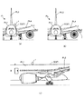
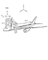
- 8 (a) and 8 (b) are front views showing an aircraft which is an example of a processing object on which a riblet structure is formed
- FIG. 8 (c) is a processing in which a riblet structure is formed. It is a side view which shows the aircraft which is an example of an object.
- FIG. 8 (a) and 8 (b) are front views showing an aircraft which is an example of a processing object on which a riblet structure is formed
- FIG. 8 (c) is a processing in which a riblet structure is formed.
- It is a side view which shows the aircraft which
- FIG. 9 is a plan view showing a plurality of processed shot regions set on the surface of the coating film.
- FIG. 10 is a cross-sectional view showing a processing apparatus that performs one step of a processing operation for forming a riblet structure.
- FIG. 11 (a) is a cross-sectional view showing a processing apparatus that performs one step of the processing operation for forming the riblet structure, and
- FIG. 11 (b) shows one step of the processing operation shown in FIG. 11 (a). It is a top view which shows the surface of the coating film performed.
- FIG. 12 is a plan view showing the scanning locus of the processing light (that is, the moving locus of the target irradiation region) during the period in which the scanning operation and the step operation are repeated.
- FIG. 10 is a cross-sectional view showing a processing apparatus that performs one step of a processing operation for forming a riblet structure.
- FIG. 11 (a) is a cross-sectional view showing a processing apparatus
- FIG. 13 is a cross-sectional view showing a processing apparatus that performs one step of a processing operation for forming a riblet structure.
- FIG. 14 (a) is a cross-sectional view showing a processing apparatus that performs one step of the processing operation for forming the riblet structure, and
- FIG. 14 (b) shows one step of the processing operation shown in FIG. 14 (a). It is a top view which shows the surface of the coating film performed.
- FIG. 15 is a cross-sectional view showing a processing apparatus that performs one step of a processing operation for forming a riblet structure.
- FIG. 16 is a cross-sectional view showing a processing apparatus that performs one step of a processing operation for forming a riblet structure.
- FIG. 17 is a cross-sectional view showing a processing apparatus that performs one step of a processing operation for forming a riblet structure.
- FIG. 18 is a cross-sectional view showing a processing apparatus that performs one step of a processing operation for forming a riblet structure.
- FIG. 19 is a cross-sectional view showing a processing apparatus that performs one step of a processing operation for forming a riblet structure.
- FIG. 20 is a cross-sectional view showing a processing apparatus that performs one step of a processing operation for forming a riblet structure.
- FIG. 21 is a cross-sectional view schematically showing the overall structure of the processing system of the second embodiment.
- FIG. 22 is a cross-sectional view schematically showing the overall structure of the processing system of the third embodiment.
- FIGS. 23 (a) and 23 (b) is a plan view showing a test structure formed when the drive system is controlled based on the measurement result of the position measuring device.
- FIGS. 24 (a) and 24 (b) is a sensitive member when the processing light is irradiated while controlling the drive system as in the case of forming the test structure based on the measurement result of the position measuring device. It is a top view which shows the characteristic change pattern formed in.
- FIG. 25 is a cross-sectional view schematically showing the structure of the processing system of the fourth embodiment.
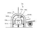
- FIG. 26 is a perspective view schematically showing the structure of the processing system of the fifth embodiment.
- FIG. 27 is a front view schematically showing the structure of the processing system of the fifth embodiment.
- FIG. 28 is a side view schematically showing the structure of the processing system of the fifth embodiment.
- FIG. 29 is an enlarged front view showing a part of the structure of the processing system of the fifth embodiment.
- FIG. 30 is a cross-sectional view showing the structure of the drive system of the sixth embodiment.
- FIG. 31 is a cross-sectional view showing the structure of the drive system according to the sixth embodiment.
- FIG. 32 is a front view showing a light irradiating device whose posture has changed so as to irradiate processing light from diagonally downward to diagonally upward of the aircraft, which is the object to be processed.
- FIG. 32 is a front view showing a light irradiating device whose posture has changed so as to irradiate processing light from diagonally downward to diagonally upward of the aircraft, which is the object to be processed.
- FIG. 33 is a cross-sectional view showing a plurality of second drive systems connecting the light irradiation device shown in FIG. 32 and the first drive system.
- FIG. 34 is a cross-sectional view schematically showing the structure of the processing system of the seventh embodiment.
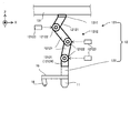
- FIG. 35 shows an example of an end effector.
- FIGS. 36 (a) to 36 (e) shows an example of an end effector.
- each of the X-axis direction and the Y-axis direction is a horizontal direction (that is, a predetermined direction in the horizontal plane), and the Z-axis direction is a vertical direction (that is, a direction orthogonal to the horizontal plane). Yes, in effect, in the vertical direction).
- the rotation directions (in other words, the inclination direction) around the X-axis, the Y-axis, and the Z-axis are referred to as the ⁇ X direction, the ⁇ Y direction, and the ⁇ Z direction, respectively.
- the Z-axis direction may be the direction of gravity.
- the XY plane may be horizontal.
- machining system SYSa Processing system SYSSa of the first embodiment
- machining system SYSa the machining system SYS of the first embodiment
- machining system SYSa the machining system SYS of the first embodiment
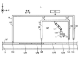
- FIG. 1 is a cross-sectional view schematically showing the structure of the processing system SYSA of the first embodiment.
- the processing system SYS processes the coating film SF formed (for example, applied) on the surface of the object to be processed S.
- the object to be processed S may be, for example, a metal, an alloy (for example, duralumin, etc.), a resin (for example, CFRP (Carbon Fiber Reinforced Plastic), etc.), or It may be glass or an object made of any other material.
- the coating film SF is a coating film that covers the surface of the object S to be processed. Therefore, the coating film SF may be referred to as a coating layer.
- the object to be processed S serves as a base material for the coating film SF.
- the thickness of the coating film SF is, for example, tens of micrometers to hundreds of micrometers, but may be any other size.
- the paint constituting the coating film SF may contain, for example, a resin-based paint, or may contain other types of paint.
- Resin-based paints include, for example, acrylic paints (eg, paints containing acrylic polyols), polyurethane-based paints (eg, paints containing polyurethane polyols), polyester-based paints (eg, paints containing polyester polyols), It may contain at least one of a vinyl-based paint, a fluorine-based paint (for example, a paint containing a fluorine-based polyol), a silicon-based paint, and an epoxy-based paint.
- FIG. 1 shows an example in which a processing system SYSa (particularly, a processing apparatus 1 described later included in the processing system SYSa) is arranged on a processing object S having a surface along a horizontal plane (that is, an XY plane). ..
- the processing system SYSA is not always arranged on the processing object S having a surface along the horizontal plane.
- the processing system SYSA may be arranged on the processing object S having a surface intersecting a horizontal plane.
- the processing system SYSA may be arranged so as to hang from the processing object S.
- the X-axis direction and the Y-axis direction may be defined as directions along the surface of the workpiece S (typically, parallel directions) for convenience, and the Z-axis direction may be defined for convenience. It may be defined as a direction intersecting the surface of the object S to be processed (typically, a direction orthogonal to the surface).
- the processing system SYSa irradiates the coating film SF with processing light EL in order to process the coating film SF.
- the processing light EL may be any kind of light as long as the coating film SF can be processed by irradiating the coating film SF.
- the processing light EL may be a laser light.
- the processing light EL may be light of any wavelength as long as the coating film SF can be processed by irradiating the coating film SF.
- the description will proceed with reference to an example in which the processed light EL is invisible light (for example, at least one of infrared light and ultraviolet light).
- the processed light EL may be visible light.
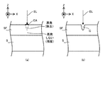
- FIGS. 2 (a) and 2 (b) are cross-sectional views schematically showing a state of processing of the coating film SF formed on the surface of the object to be processed S.
- the processing system SYSa irradiates the target irradiation region EA set on the surface of the coating film SF with the processing light EL.
- the target irradiation area EA is an area where the processing system SYSA is scheduled to irradiate the processing light EL.
- the coating film SF that overlaps with the target irradiation region EA that is, the coating film located on the ⁇ Z side of the target irradiation region EA. A part of is evaporated by the processing light EL.
- all of the coating film SF overlapping the target irradiation region EA does not evaporate. That is, in the thickness direction of the coating film SF, while a part of the coating film SF overlapping the target irradiation region EA (specifically, a portion of the coating film SF that is relatively close to the target irradiation region EA) evaporates. The other part of the coating film SF that overlaps the target irradiation region EA (specifically, the portion of the coating film SF that is relatively far from the target irradiation region EA) does not evaporate. In other words, the coating film SF evaporates only to the extent that the work object S is not exposed from the coating film SF.
- the characteristics of the processing light EL may be set to desired characteristics that evaporate the coating film SF only to the extent that the processing object S is not exposed from the coating film SF.
- the characteristics of the processing light EL may be set to desired characteristics that do not affect the processing object S by irradiation with the processing light EL.
- the characteristics of the processing light EL may be set to desired characteristics that affect only the coating film SF by irradiation with the processing light EL.
- the characteristics of the processing light EL are the wavelength of the processing light EL, the amount of energy transmitted from the processing light EL to the surface of the coating film SF per unit time and / or the amount of energy per unit area, and the surface of the coating film SF.
- It includes at least one of the intensity distribution of the processing light EL, the irradiation time of the processing light EL on the surface of the coating film SF, and the size (for example, spot diameter and area) of the processing light EL on the surface of the coating film SF. May be good.
- the energy (that is, the intensity) of the processing light EL irradiated to the coating film SF is determined so as not to affect the processing object S by the irradiation of the processing light EL.
- the energy of the processing light EL is determined so that the processing light EL does not penetrate the coating film SF and reach the processing object S. In other words, the energy of the processing light EL is determined so as to affect only the coating film SF by the irradiation of the processing light EL.
- the coating film SF is removed at the portion where the coating film SF has evaporated.
- the coating film SF remains as it is. That is, as shown in FIG. 2B, the coating film SF is partially removed in the portion irradiated with the processing light EL.
- the thickness of the coating film SF becomes thinner in the portion irradiated with the processing light EL as compared with the portion not irradiated with the processing light EL. In other words, as shown in FIG.
- the surface of the object to be processed S is irradiated with the coating film SF which remains relatively thick because the processing light EL is not irradiated, and the processing light EL. Therefore, there is a coating film SF that is relatively thin. That is, the thickness of the coating film SF is adjusted at least partially by irradiation with the processing light EL. By irradiating the processing light EL, a part of the coating film SF is removed in the thickness direction (in the example shown in FIG. 2B, the Z-axis direction). As a result, a recess (in other words, a groove) C corresponding to a portion where the coating film SF is relatively thin is formed on the surface of the coating film SF.
- the "operation of processing the coating film SF" in the first embodiment includes an operation of adjusting the thickness of the coating film SF, an operation of removing a part of the coating film SF, and forming a recess C in the coating film SF. Includes at least one of the actions.
- the coating film SF evaporates by absorbing the processing light EL. That is, the coating film SF is removed by being photochemically decomposed, for example, by transmitting the energy of the processing light EL to the coating film SF.
- the processing light EL is laser light
- the phenomenon in which the energy of the processing light EL is transmitted to the coating film SF to photochemically decompose and remove the coating film SF and the like is called laser ablation.
- the coating film SF contains a material capable of absorbing the processed light EL. Specifically, for example, the coating film SF absorbs light in a wavelength band including a wavelength band different from that of visible light when the processing light EL is invisible light.
- It may contain a material whose rate) is equal to or higher than a predetermined first absorption threshold.
- light in a wavelength band in which the absorption rate by the coating film SF is equal to or higher than a predetermined first absorption threshold value may be used as the processing light EL.
- the material constituting the coating film SF may contain a dye (specifically, for example, at least one of a pigment and a dye).
- the dye may be a dye that exhibits a desired color when irradiated with visible light.
- the coating film SF containing such a dye will exhibit a desired color.
- the dye has a first wavelength including a wavelength recognized by humans as light of a desired color by being reflected by the coating film SF in the wavelength band of visible light so that the coating film SF exhibits a desired color. It may have a characteristic that the absorption rate of light in the band is different from the absorption rate of light in the second wavelength band of visible light, which is different from the first wavelength band.
- the dye may have a characteristic that the absorption rate of light in the first wavelength band is smaller than the absorption rate of light in the second wavelength band.
- the absorption rate of light in the first wavelength band is equal to or less than a predetermined second absorption threshold (however, the second absorption threshold is smaller than the first absorption threshold), and the light in the second wavelength band is light.
- a dye that can appropriately absorb such invisible light EL and exhibits a desired color for example, a near-infrared absorbing dye manufactured by Spectrum Info Co., Ltd.
- the dye When the coating film SF contains a dye, the dye may be a dye that is transparent to visible light. As a result, the coating film SF containing such a dye becomes a transparent film (so-called clear coat).
- transparent film as used herein may mean a film through which light in at least a part of the wavelength bands of visible light can pass.
- the dye may have a property of not absorbing much visible light (that is, reflecting it correspondingly) so that the coating film SF becomes transparent.
- the dye may have a characteristic that the absorption rate of visible light becomes smaller than a predetermined fourth absorption threshold value.
- a dye that can appropriately absorb such invisible processed light EL but becomes transparent to visible light for example, a near-infrared absorbing dye manufactured by Spectrum Info Co., Ltd. (as an example, tetrafluoroboron).
- 6-Chloro-2-[(E) -2-(3- ⁇ (E) -2- [6-chloro-1-ethylbenzo [cd] indole-2 (1H) -iriden] ethylidene ⁇ -2-phenyl -1-Cyclopentene-1-yl) ethenyl] -1-ethylbenzo [cd] indole) can be mentioned.
- the processing system SYSa in order to process the coating film SF, includes a processing device 1 and a control device 2. Further, the processing device 1 includes a light irradiation device 11, a drive system 12, an accommodation device 13, a support device 14, a drive system 15, an exhaust device 16, a gas supply device 17, and a position measurement device 18. Be prepared.
- the light irradiation device 11 can irradiate the coating film SF with the processed light EL under the control of the control device 2.
- the light irradiating device 11 uses the processed light EL as shown in FIG. 3A which is a cross-sectional view schematically showing the structure of the light irradiating device 11. It includes a light source system 111 that can emit light, and an optical system 112 that guides the processed light EL emitted from the light source system 111 to the coating film SF.
- the light source system 111 emits, for example, a plurality of processed light ELs at the same time. However, the light source system 111 may emit a single processed light EL. At this time, the light irradiation device 11 may emit a single processed light EL. In order to emit a plurality of processed light ELs, the light source system 111 includes a plurality of light sources 1111 as shown in FIG. 3B, which is a cross-sectional view schematically showing an example of the structure of the light source system 111. .. The plurality of light sources 1111 are arranged in a row at equal intervals. Each light source 1111 emits pulsed light as processed light EL.
- each light source 1111 may emit pulsed light having a relatively short pulse width as processed light EL.
- each light source 1111 may emit pulsed light having a pulse width of 1000 nanoseconds or less as processed light EL.
- each light source 1111 may emit pulsed light having a pulse width on the order of picoseconds as processed light EL, or emit pulsed light having a pulse width on the order of femtoseconds as processed light EL. May be good.
- the light source system 111 is derived from a single light source 1111 and the single light source 1111.
- a branching device 1112 that branches light into a plurality of processed light ELs may be provided.
- the plurality of ejection ports from which the plurality of processed optical ELs branched by the turnout 1112 are respectively ejected are arranged in a row at equal intervals.
- the turnout 1112 at least one of an optical fiber coupler, a waveguide type splitter, a lens array, a diffractive optical element, a spatial light modulator, and the like can be mentioned.
- the optical system 112 includes a focus lens 1121, a galvanometer mirror 1122, and an f ⁇ lens 1123.
- the plurality of processed light ELs are applied to the coating film SF via the focus lens 1121, the galvanometer mirror 1122, and the f ⁇ lens 1123.
- the focus lens 1121 is composed of one or more lenses, and by adjusting the position of at least a part of the lenses along the optical axis direction, the convergence position BF of a plurality of processed optical ELs (in other words, the focusing position, Alternatively, it is an irradiation position in the optical axis direction, that is, an optical element for adjusting the focal position of the optical system 112).
- the galvano mirror 1122 is such that a plurality of processed light ELs scan the surface of the coating film SF (that is, a plurality of target irradiation regions EA irradiated with the plurality of processing light ELs move on the surface of the coating film SF). , A plurality of processed light ELs are deflected.
- the galvano mirror 1122 can function as an irradiation position changing device that changes the irradiation positions of the plurality of processed light ELs on the coating film SF with respect to the light irradiation device 11.
- the galvano mirror 1122 may allow a plurality of processed light ELks emitted by the optical system 112 to sweep the surface of the coating film SF.
- the galvano mirror 112 includes an X scanning mirror 1122X and a Y scanning mirror 1122Y.
- the X scanning mirror 1122X reflects a plurality of processed light ELs toward the Y scanning mirror 1122Y.
- the X scanning mirror 1122X can swing or rotate in the ⁇ Y direction (that is, the rotation direction around the Y axis).
- the plurality of processed optical ELs scan the surface of the coating film SF along the X-axis direction. Due to the swing or rotation of the X scanning mirror 1122X, the plurality of target irradiation regions EA move along the X-axis direction on the coating film SF.
- the X scanning mirror 1122X changes the relative positional relationship between the plurality of target irradiation regions EA and the coating film SF along the X-axis direction.
- the Y scanning mirror 1122Y reflects a plurality of processed light ELs toward the f ⁇ lens 1123.
- the Y scanning mirror 1122Y can swing or rotate in the ⁇ X direction (that is, the rotation direction around the X axis).
- the plurality of processed light ELs scan the surface of the coating film SF along the Y-axis direction. Due to the swing or rotation of the Y scanning mirror 1122Y, the plurality of target irradiation regions EA move along the Y-axis direction on the coating film SF.
- the Y scanning mirror 1122Y changes the relative positional relationship between the plurality of target irradiation regions EA and the coating film SF along the Y-axis direction.
- the f ⁇ lens 1123 is an optical element for condensing a plurality of processed light ELs from the galvano mirror 1122 on the coating film SF.
- the f ⁇ lens 1123 is located on the light emitting side of the optical system 112 among the optical elements included in the optical system 112 (in other words, it is located closest to the coating film SF or at the end of the optical path of a plurality of processed optical ELs. ) Termination optical element.
- the optical system 112 may include an optical element (for example, a cover lens or the like) provided on the light emitting side of the f ⁇ lens 1123.
- the f ⁇ lens 1123 may be configured to be removable from the optical system 112. As a result, after removing the old f ⁇ lens 1123 from the optical system 112, another f ⁇ lens 1123 can be attached to the optical system 112.
- the optical system 112 includes an optical element (for example, a cover lens) provided on the emission side of the f ⁇ lens 1123, the optical element becomes a terminal optical element and the optical element becomes the optical system 112. It may be configured to be removable.
- the traveling directions of the plurality of processed light ELs from the optical system 112 are, for example, parallel to each other.
- the coating film SF is simultaneously irradiated with a plurality of processing light ELs whose traveling directions are parallel to each other. That is, a plurality of target irradiation regions EA are simultaneously set on the coating film SF. Therefore, the throughput related to the processing of the coating film SF is improved as compared with the case where the coating film SF is irradiated with a single processing light EL.
- the traveling directions of the plurality of processed light ELs from the optical system 112 do not have to be parallel to each other.
- the light irradiation device 11 does not have to include the light source system 111.
- the light irradiation device 11 may irradiate the coating film SF with a plurality of processed light ELs emitted from the light source system 111 arranged outside the light irradiation device 11 by using the optical system 112.
- the light irradiation device 11 is provided outside the light irradiation device 11.
- a plurality of processed light ELs may be incident from the arranged light source system 111 via an optical transmission member 113 such as an optical fiber.
- the light irradiation device 11 may irradiate the coating film SF with the plurality of processed light ELs incident on the light irradiation device 11 via the transmission member 113 using the optical system 112.
- FIG. 4 shows an example in which the optical system 112 is housed in the housing 114, the optical system 112 may not be housed in the housing 114. That is, the light irradiation device 11 may or may not include the housing 114. Further, even when the light irradiation device 11 includes the light source system 111, the optical system 112 may be housed in the housing 114, or the optical system 112 may not be housed in the housing 114. Good.
- the light source system 111 may be housed in the housing 114, or the light source system 111 may not be housed in the housing 111.
- the optical transmission member 113 a light pipe, a relay optical system including one or more lenses and mirrors, and the like may be used.
- the drive system 12 under the control of the control device 2, makes the light irradiation device 11 with respect to the coating film SF (that is, with respect to the processing object S on which the coating film SF is formed on the surface). Move. That is, the drive system 12 moves the light irradiation device 11 with respect to the coating film SF so as to change the relative positional relationship between the light irradiation device 11 and the coating film SF.
- the relative positional relationship between the light irradiation device 11 and the coating film SF is changed, the relative positional relationship between the coating film SF and the plurality of target irradiation regions EA to which the plurality of processed light ELs are irradiated respectively.
- the positional relationship is also changed. Therefore, it can be said that the drive system 12 moves the light irradiation device 11 with respect to the coating film SF so as to change the relative positional relationship between the plurality of target irradiation regions EA and the coating film SF.
- the drive system 12 may move the light irradiation device 11 along the surface of the coating film SF.
- the drive system 12 since the surface of the coating film SF is a plane parallel to at least one of the X-axis and the Y-axis, the drive system 12 is irradiated with light along at least one of the X-axis and the Y-axis.
- the device 11 may be moved.
- the target irradiation region EA moves along at least one of the X-axis and the Y-axis on the coating film SF. That is, the range in which the light irradiation device 11 can irradiate the processed light EL is changed.
- the drive system 12 may move the light irradiation device 11 along the thickness direction of the coating film SF (that is, the direction intersecting the surface of the coating film SF).
- the drive system 12 may move the light irradiation device 11 along the Z-axis direction.
- the drive system 12 may move the light irradiation device 11 along at least one rotation direction in the ⁇ X direction, the ⁇ Y direction, and the ⁇ Z direction in addition to at least one of the X-axis, the Y-axis, and the Z-axis.
- the drive system 12 supports the light irradiation device 11 and moves the supporting light irradiation device 11.
- the drive system 12 may include, for example, a first support member that supports the light irradiation device 11, and a first movement mechanism that moves the first support member.
- the drive system 12 includes a first drive system 121 and a second drive system 122.
- a second drive system 121 is attached to the first drive system 121.
- the first drive system 121 supports the second drive system 122.
- the light irradiation device 11 is attached to the second drive system 122 via the attachment member 19.
- the second drive system 122 supports the light irradiation device 11 via the mounting member 19. Therefore, the second drive system 122 may substantially function as a connecting device for connecting the first drive system 121 and the light irradiation device 11.
- the second drive system 122 may support the light irradiation device 11 without going through the mounting member 19.
- the second drive system 122 may support the light irradiation device 11 by supporting the housing 114 shown in FIG.
- the first drive system 121 moves the second drive system 122 with respect to the coating film SF under the control of the control device 2. That is, the first drive system 121 functions as a moving device that moves the second drive system 122 with respect to the coating film SF. Since the light irradiation device 11 is attached to the second drive system 122, the first drive system 121 moves the light irradiation device 11 with respect to the coating film SF by moving the second drive system 122. It can be said that. That is, the first drive system 121 moves the light irradiation device 11 together with the second drive system 122. The second drive system 122 moves the second drive system 122 with respect to the coating film SF under the control of the control device 2. That is, the second drive system 122 functions as a moving device that moves the light irradiation device 11 with respect to the coating film SF.
- the accommodating device 13 includes a ceiling member 131 and a partition wall member 132.
- the ceiling member 131 is arranged on the + Z side of the light irradiation device 11.
- the ceiling member 131 is a plate-shaped member along the XY plane.
- the ceiling member 131 supports the drive system 12.
- the first drive system 121 is attached to the ceiling member 131. That is, the ceiling member 131 supports the first drive system 121.
- the second drive system 122 is attached to the first drive system 121 as described above, the second drive system 122 is attached to the ceiling member 131 via the first drive system 121. That is, the ceiling member 131 supports the second drive system 122 via the first drive system 121.
- the light irradiation device 11 is attached to the second drive system 122 as described above, the light irradiation device 11 is attached to the ceiling member 131 via the first drive system 121 and the second drive system 122. ..
- the ceiling member 131 supports the light irradiation device 11 via the first drive system 121 and the second drive system 122.
- a partition wall member 132 is arranged on the outer edge (or its vicinity) of the surface of the ceiling member 131 on the ⁇ Z side.
- the partition wall member 132 is a tubular (for example, cylindrical or rectangular tubular) member extending from the ceiling member 131 toward the ⁇ Z side.
- the space surrounded by the ceiling member 131 and the partition wall member 132 serves as an accommodation space SP for accommodating the light irradiation device 11 and the drive system 12. Therefore, the drive system 12 described above moves the light irradiation device 11 within the accommodation space SP.
- the accommodation space SP includes a space between the light irradiation device 11 and the coating film SF (particularly, a space including an optical path of the processed light EL). More specifically, the accommodation space SP includes a space between the terminal optical element (for example, f ⁇ lens 1123) included in the light irradiation device 11 and the coating film SF (particularly, a space including an optical path of the processed light EL). I'm out.
- Each of the ceiling member 131 and the partition wall member 132 is a member capable of blocking the processed light EL. That is, each of the ceiling member 131 and the partition wall member 132 is opaque with respect to the wavelength of the processed light EL. As a result, the processed light EL propagating in the accommodation space SP does not leak to the outside of the accommodation space SP (that is, the outside of the accommodation device 13).
- Each of the ceiling member 131 and the partition wall member 132 may be a member capable of dimming the processed light EL. That is, each of the ceiling member 131 and the partition wall member 132 may be translucent with respect to the wavelength of the processed light EL.
- each of the ceiling member 131 and the partition wall member 132 is a member that does not allow unnecessary substances generated by irradiation with the processing light EL to pass through (that is, can be shielded).
- An example of an unnecessary substance is the vapor of the coating film SF.
- the end portion of the partition wall member 132 (specifically, the end portion on the coating film SF side, and in the example shown in FIG. 1, the end portion on the ⁇ Z side) 134 is in contact with the surface of the coating film SF.
- the accommodating device 13 that is, the ceiling member 131 and the partition wall member 132 cooperates with the coating film SF to maintain the airtightness of the accommodating space SP.
- the shape thereof (particularly, the contact surface of the end portion 134 in contact with the coating film SF (in the example shown in FIG. 1). It is possible to change the shape of the ⁇ Z side surface), the same applies hereinafter).
- the shape of the end portion 134 becomes a flat shape similarly to the coating film SF.
- the shape of the end portion 134 becomes a curved surface shape similarly to the coating film SF.
- the airtightness of the accommodation space SP is improved as compared with the case where the end portion 134 cannot change its shape according to the shape of the surface of the coating film SF.
- An example of the end 134 whose shape can be changed is the end 134 formed of an elastic member (in other words, a flexible member) such as rubber.
- a bellows-shaped end portion having an elastic structure may be used.
- the end portion 134 may be able to adhere to the coating film SF in a state of being in contact with the coating film SF.
- the end portion 134 may be provided with an adsorption mechanism capable of adsorbing to the coating film SF.
- the airtightness of the accommodation space SP is further improved as compared with the case where the end portion 134 does not adhere to the coating film SF.
- the end portion 134 does not have to be able to adhere to the coating film SF. Even in this case, as long as the end portion 134 comes into contact with the coating film SF, the airtightness of the accommodation space SP is still maintained accordingly.
- the partition wall member 132 is a member that can be expanded and contracted along the Z-axis direction by a drive system (for example, an actuator) (not shown) that operates under the control of the control device 2.
- the partition member 132 may be a bellows-shaped member (so-called bellows).
- the partition member 132 can be expanded and contracted by expanding and contracting the bellows portion.
- the partition member 132 may include a telescopic pipe in which a plurality of hollow cylindrical members having different diameters are combined. In this case, the partition member 132 can be expanded and contracted by the relative movement of the plurality of cylindrical members.
- the state of the partition wall member 132 is at least the first extended state in which the partition wall member 132 extends along the Z-axis direction and the length in the Z-axis direction is relatively long, and the partition wall member 132 contracts along the Z-axis direction. By doing so, it is possible to set the first reduced state in which the length in the Z-axis direction is relatively short.
- the end portion 134 When the partition member 132 is in the first extended state, the end portion 134 is in the first contact state in which it can come into contact with the coating film SF. On the other hand, when the partition member 132 is in the first contracted state, the end portion 134 is in the first non-contact state in which it does not come into contact with the coating film SF. That is, when the partition member 132 is in the first reduced state, the end portion 134 is in the first non-contact state separated from the coating film SF on the + Z side.
- the configuration for switching the state of the end portion 134 between the first contact state and the first non-contact state is not limited to the configuration in which the partition wall member 132 is expanded and contracted.
- the state of the end 134 may be switched between the first contact state and the first non-contact state by making the accommodating device 13 itself movable along the ⁇ Z direction.
- the accommodating device 13 further includes a detection device 135.
- the detection device 135 detects unnecessary substances (that is, substances generated by irradiation of the processing light EL) in the accommodation space SP.
- the detection result of the detection device 135 is referred to by the control device 2 when the state of the partition wall member 132 is changed from the first extended state to the first reduced state, as will be described in detail later.
- the support device 14 supports the accommodating device 13. Since the accommodating device 13 supports the drive system 12 and the light irradiation device 11, the support device 14 substantially supports the drive system 12 and the light irradiation device 11 via the accommodating device 13.
- the support device 14 includes a beam member 141 and a plurality of leg members 142.
- the beam member 141 is arranged on the + Z side of the accommodating device 13.
- the beam member 141 is a beam-shaped member extending along the XY plane.
- the beam member 141 supports the accommodating device 13 via the support member 143.
- a plurality of leg members 142 are arranged on the beam member 141.
- the leg member 142 is a rod-shaped member extending from the beam member 141 toward the ⁇ Z side.
- the end portion of the leg member 142 (specifically, the end portion on the coating film SF side, and in the example shown in FIG. 1, the end portion on the ⁇ Z side) 144 is in contact with the surface of the coating film SF.
- the support device 14 is supported by the coating film SF (that is, by the workpiece S). That is, the support device 14 supports the accommodating device 13 in a state where the end portion 144 is in contact with the coating film SF (in other words, in a state where the support device 14 is supported by the coating film S). Similar to the end 134 of the accommodating device 13, the end portion 144 contacts the coating film SF among the end portions 144 according to the shape of the surface of the coating film SF when it comes into contact with the coating film SF.
- the end portion 144 may be attached to the coating film SF in a state of being in contact with the coating film SF.
- the end portion 144 may be provided with an adsorption mechanism capable of adsorbing to the coating film SF.
- the stability of the support device 14 is improved as compared with the case where the end portion 144 does not adhere to the coating film SF.
- the end portion 144 does not have to be able to adhere to the coating film SF.
- the beam member 141 is a member that can be expanded and contracted along at least one of the X-axis and the Y-axis (or along an arbitrary direction along the XY plane) by the drive system 15 that operates under the control of the control device 2. is there.
- the beam member 141 may include a telescopic pipe in which a plurality of tubular members having different diameters are combined. In this case, the beam member 141 can be expanded and contracted by the relative movement of the plurality of tubular members.
- the leg member 142 is a member that can be expanded and contracted along the Z-axis direction by the drive system 15 that operates under the control of the control device 2.
- the leg member 142 may include a telescopic pipe in which a plurality of tubular members having different diameters are combined.
- the leg member 142 can be expanded and contracted by the relative movement of the plurality of tubular members.
- the state of the leg member 142 is at least a second extended state in which the leg member 142 extends along the Z-axis direction and the length in the Z-axis direction is relatively long, and the leg member 142 contracts along the Z-axis direction. By doing so, it is possible to set the second reduced state in which the length in the Z-axis direction is relatively short.
- the end portion 144 When the leg member 142 is in the second extended state, the end portion 144 is in the second contact state capable of contacting the coating film SF. On the other hand, when the leg member 142 is in the second reduced state, the end portion 144 is in the second non-contact state in which it does not come into contact with the coating film SF. That is, when the leg member 142 is in the second contracted state, the end portion 144 is in the second non-contact state separated from the coating film SF on the + Z side.
- the drive system 15 moves the support device 14 with respect to the coating film SF (that is, with respect to the processing object S on which the coating film SF is formed on the surface) under the control of the control device 2. That is, the drive system 15 moves the support device 14 with respect to the coating film SF so as to change the relative positional relationship between the support device 14 and the coating film SF. Since the support device 14 supports the accommodating device 13, the drive system 15 substantially moves the accommodating device 13 with respect to the coating film SF by moving the support device 14. That is, the drive system 15 substantially moves the support device 14 with respect to the coating film SF so as to change the relative positional relationship between the accommodating device 13 and the coating film SF. Further, the accommodating device 13 supports the light irradiation device 11 via the drive system 12.
- the drive system 15 can substantially move the light irradiation device 11 with respect to the coating film SF by moving the support device 14. That is, the drive system 15 can substantially move the support device 14 with respect to the coating film SF so as to change the relative positional relationship between the light irradiation device 11 and the coating film SF. In other words, the drive system 15 may move the support device 14 with respect to the coating film SF so as to substantially change the relative positional relationship between the plurality of target irradiation regions EA and the coating film SF. it can.
- the drive system 15 expands and contracts the beam member 141 under the control of the control device 2 in order to move the support device 14. Further, the drive system 15 expands and contracts the plurality of leg members 142 under the control of the control device 2 in order to move the support device 14. The movement mode of the support device 14 by the drive system 15 will be described in detail later with reference to FIGS. 9 to 20.
- the exhaust device 16 is connected to the accommodation space SP via the exhaust pipe 161.
- the exhaust device 16 can exhaust the gas in the accommodation space SP.
- the exhaust device 16 can suck unnecessary substances generated by the irradiation of the processing light EL from the accommodation space SP to the outside of the accommodation space SP by exhausting the gas in the accommodation space SP.
- this unnecessary substance is present on the optical path of the processing light EL, it may affect the irradiation of the coating film SF with the processing light EL. Therefore, the exhaust device 16 particularly sucks unnecessary substances together with the gas in the space from the space including the optical path of the processed light EL between the terminal optical element of the optical system 112 and the coating film SF.
- the unnecessary substance sucked from the accommodation space SP by the exhaust device 16 is discharged to the outside of the processing device 1 through the filter 162.
- the filter 162 adsorbs unnecessary substances.
- the filter 162 may be removable or replaceable.
- the gas supply device 17 is connected to the accommodation space SP via an intake pipe 171.
- the gas supply device 17 can supply gas to the accommodation space SP.
- Examples of the gas supplied to the accommodation space SP include at least one of air, CDA (clean dry air) and an inert gas. Nitrogen gas is an example of an inert gas.
- the gas supply device 17 supplies the CDA. Therefore, the accommodation space SP becomes a space purged by the CDA. At least a part of the CDA supplied to the accommodation space SP is sucked by the exhaust device 16. The CDA sucked from the accommodation space SP by the exhaust device 16 passes through the filter 162 and is discharged to the outside of the processing system SYS.
- the gas supply device 17 particularly supplies a gas such as CDA to the optical surface 1124 on the accommodation space SP side of the f ⁇ lens 1123 shown in FIG. 3 (that is, the optical surface on the accommodation space SP side of the terminal optical element of the optical system 112). .. Since the optical surface 1124 faces the accommodation space SP, it may be exposed to unnecessary substances generated by irradiation with the processing light EL. As a result, unnecessary substances may adhere to the optical surface 1124. Further, since the processing light EL passes through the optical surface 1124, the processing light EL passing through the optical surface 1124 may burn (that is, stick) unnecessary substances adhering to the optical surface 1124.
- a gas such as CDA
- Unwanted substances adhering to (and further adhering to) the optical surface 1124 may become stains on the optical surface 1124 and affect the characteristics of the processed light EL.
- a gas such as CDA
- contact between the optical surface 1124 and an unnecessary substance is prevented. Therefore, the adhesion of dirt to the optical surface 1124 is prevented. Therefore, the gas supply device 17 also functions as an adhesion prevention device for preventing the adhesion of dirt to the optical surface 1124.
- the gas supply device 17 can also function as an adhesion prevention device for removing dirt adhering to the optical surface 1124.
- the position measuring device 18 measures the relative positional relationship between the coating film SF and the light irradiation device 11. That is, the position measuring device 18 measures the relative positional relationship between the processing object S and the light irradiation device 11. In the first embodiment, the position measuring device 18 measures the position of the coating film SF with respect to the light irradiation device 11. That is, the position measuring device 18 measures the position of the processing object S with respect to the light irradiation device 11.
- the position measuring device 18 may measure the coating film SF. That is, the position measuring device 18 may measure the work target SF. In this case, the position measuring device 18 may be referred to as an object measuring device because it measures an object including at least one of the coating film SF and the object S to be processed.
- the position measuring device 18 may be arranged at a fixed position with respect to the light irradiation device 11 (particularly, the optical system 112).
- the position measuring device 18 may be arranged at a position where the relative position with respect to the light irradiation device 11 is fixed.
- the position measuring device 18 may be arranged at a position where the relative positions of the light irradiation device 11 and the position measuring device 18 do not change even if the drive system 12 moves the light irradiation device 11.
- FIG. 1 shows an example in which the position measuring device 18 is attached to the attachment member 19 to which the light irradiation device 11 is attached.
- the position measuring device 18 may be attached to a member different from the attachment member 19.
- the position measuring device 18 may be attached to the light irradiation device 11.
- the position measuring device 18 may be attached to the housing 114 (see FIG. 4) described above.
- the output from the position measuring device 18 is the coating film on the light irradiation device 11. It will include information about the location of the membrane SF.
- the measurement result of the position measuring device 18 includes information regarding the position of the coating film SF with respect to the position measuring device 18. That is, the measurement result of the position measuring device 18 includes information regarding the position of the coating film SF in the measurement coordinate system of the position measuring device 18.
- the position measuring device 18 is arranged at a position fixed with respect to the light irradiation device 11, the information regarding the position of the coating film SF with respect to the position measuring device 18 is substantially the position measuring device.
- the information regarding the position of the coating film SF with respect to the light irradiation device 11 arranged at a fixed position with respect to 18 is included. Therefore, the control device 2 can appropriately specify the position of the coating film SF with respect to the light irradiation device 11.
- the position measuring device 18 may be any kind of measuring device as long as it can measure the coating film SF.
- the position measuring device 18 may include an imaging device (that is, a camera) capable of imaging an object such as a coating film SF.
- the position measuring device 18 includes an irradiation device that irradiates the coating film SF with measurement light that draws a predetermined pattern on the coating film SF, and an imaging device that images a pattern drawn on the coating film SF by the measurement light. May be good.
- the position measuring device 18 may be a measuring device that measures the coating film SF by a non-contact method (for example, at least one of a light detection method, a sound wave detection method, a radio wave detection method, and the like).
- a plurality of position measuring devices 18 may be provided.
- the measurement axes of the respective position measurement devices 18 may be in a relationship of intersecting (or twisting) with each other, and are parallel (or coaxial) with each other. ) May be.
- the control device 2 controls the overall operation of the processing system SYSa.
- the control device 2 controls the light irradiation device 11, the drive system 12, the accommodating device 13, and the drive system 15 so that the recess C having a desired shape is formed at a desired position, as will be described in detail later. ..
- the control device 2 may include, for example, a CPU (Central Processing Unit) (or a GPU (Graphics Processing Unit) in addition to or in place of the CPU) and a memory.
- the control device 2 functions as a device that controls the operation of the processing system SYS by the CPU executing a computer program.
- This computer program is a computer program for causing the control device 2 (for example, the CPU) to perform (that is, execute) the operation described later to be performed by the control device 2. That is, this computer program is a computer program for causing the control device 2 to function so that the processing system SYSa performs an operation described later.
- the computer program executed by the CPU may be recorded in a memory (that is, a recording medium) included in the control device 2, or may be an arbitrary storage medium built in the control device 2 or externally attached to the control device 2 (that is, a storage medium). For example, it may be recorded on a hard disk or a semiconductor memory). Alternatively, the CPU may download the computer program to be executed from a device external to the control device 2 via the network interface.
- a memory that is, a recording medium
- the CPU may download the computer program to be executed from a device external to the control device 2 via the network interface.
- the control device 2 may not be provided inside the processing system SYS, and may be provided, for example, as a server or the like outside the processing system SYS.
- the control device 2 and the processing system SYSA may be connected by a wired and / or wireless network (or a data bus and / or a communication line).
- a wired network for example, a network using a serial bus type interface represented by at least one of IEEE1394, RS-232x, RS-422, RS-423, RS-485 and USB may be used.
- a network using a parallel bus interface may be used.
- a network using an Ethernet (registered trademark) compliant interface represented by at least one of 10BASE-T, 100BASE-TX and 1000BASE-T may be used.
- a network using radio waves may be used.
- An example of a network using radio waves is a network conforming to IEEE802.1x (for example, at least one of wireless LAN and Bluetooth®).
- a network using infrared rays may be used.
- a network using optical communication may be used.
- the control device 2 and the processing system SYSA may be configured so that various types of information can be transmitted and received via the network.
- control device 2 may be able to transmit information such as commands and control parameters to the processing system SYSA via the network.
- the processing system SYSa may include a receiving device that receives information such as commands and control parameters from the control device 2 via the network.
- the first control device that performs a part of the processing performed by the control device 2 is provided inside the processing system SYS
- the second control device that performs the other part of the processing performed by the control device 2 is performed.
- the control device may be provided outside the processing system SYS.
- the recording medium for recording the computer program executed by the CPU includes CD-ROM, CD-R, CD-RW, flexible disk, MO, DVD-ROM, DVD-RAM, DVD-R, DVD + R, and DVD-RW. , DVD + RW and Blu-ray (registered trademark) optical disks, magnetic media such as magnetic tapes, magneto-optical disks, semiconductor memories such as USB memory, and any other medium capable of storing programs. May be good.
- the recording medium may include a device capable of recording a computer program (for example, a general-purpose device or a dedicated device in which the computer program is implemented in at least one form such as software and firmware).
- each process or function included in the computer program may be realized by a logical processing block realized in the control device 2 by the control device 2 (that is, the computer) executing the computer program. It may be realized by hardware such as a predetermined gate array (FPGA, ASIC) included in the control device 2, or a logical processing block and a partial hardware module that realizes a part of the hardware are mixed. It may be realized in the form of.
- FPGA predetermined gate array
- FIG. 5 is a cross-sectional view showing the structure of the first drive system 121.
- the first drive system 121 includes a base 1211 and an arm drive system 1212.
- the base 1211 is attached to the ceiling member 131 of the accommodating device 13.
- An arm drive system 1212 is attached to the base 1211.
- the base 1211 supports the arm drive system 1211.
- the base 1211 is used as a base member for supporting the arm drive system 1211.
- the arm drive system 1212 includes a plurality of arm members 12121.
- the plurality of arm members 12121 are oscillatingly connected via at least one joint member 12122. Therefore, the arm drive system 1212 is a robot having a so-called vertical articulated structure.
- the arm drive system 1212 may include a single joint (ie, the drive shaft defined by the joint member 12122).
- the arm drive system 1212 may include a plurality of joints.
- FIG. 5 shows an example in which the arm drive system 1212 has three joints.
- FIG. 5 shows an example in which the arm drive system 1212 is provided with three actuators 12123 corresponding to three joints.
- at least one arm member 12121 moves. Therefore, at least one arm member 12121 is movable with respect to the coating film SF. That is, at least one arm member 12121 can be moved so that the relative positional relationship between the at least one arm member 12121 and the coating film SF is changed
- a second drive system 122 is attached to the arm drive system 1212. Specifically, the second drive system 122 is attached to one arm member 12121 located at the position farthest from the base 1211 among the plurality of arm members 12121.
- one arm member 12121 to which the second drive system 122 is attached is referred to as a tip arm member 12124.
- the second drive system 122 may be directly attached to the tip arm member 12124, or via another member (for example, the attachment member 1213 described with reference to FIG. 30 in the sixth embodiment described later). It may be indirectly attached to the tip arm member 12124.
- the arm drive system 1212 (that is, the first drive system 121) can move the second drive system 122.
- the arm drive system 1212 can move the second drive system 122 with respect to the coating film SF.
- the arm drive system 1212 can move the second drive system 122 so that the relative positional relationship between the second drive system 122 and the coating film SF is changed.
- the arm drive system 1212 (that is, the first drive system 121) can move the light irradiation device 11.
- the control device 2 may control the arm drive system 1212 based on the measurement result of the position measuring device 18. Specifically, the control device 2 acquires information on the relative positional relationship between the coating film SF and the light irradiation device 11 based on the measurement result of the position measurement device 18, and the coating film SF and the light irradiation device 11
- the arm drive system 1212 may be controlled based on the information regarding the relative positional relationship of the above.
- the control device 2 uses a visual servo (visual servo) based on the measurement result of the position measuring device 18 (that is, the image captured by the imaging device).
- the arm drive system 1212 may be controlled.
- the visual servo may be referred to as a vision servo.
- the light irradiation device 11 may include an acceleration sensor as a motion measurement sensor for measuring the vibration thereof. In this case, the control device 2 may control the arm drive system 1212 based on the measurement result of the acceleration sensor.
- the control device 2 may control the arm drive system 1212 so that the light irradiation device 11 moves with respect to the coating film SF. That is, the control device 2 may control the arm drive system 1212 so as to change the relative position between the light irradiation device 11 and the coating film SF. At this time, the control device 2 may control the arm drive system 1212 so as to align the coating film SF and the light irradiation device 11. The control device 2 may control the arm drive system 1212 so as to align the coating film SF with the target irradiation region EA on which the processing light EL is irradiated from the light irradiation device 11.
- control device 2 may control the arm drive system 1212 so that the target irradiation region EA is set at a desired position on the coating film SF (that is, the processing light EL is irradiated).
- the control device 2 may control the arm drive system 1212 so that the target irradiation region EA moves along a desired path on the coating film SF.
- the control device 2 may control the arm drive system 1212 by using the output from the encoder provided at the joint portion of the arm drive system 1212 and detecting the angle between the plurality of arm members 12121.
- the "relative position between the light irradiation device 11 and the coating film SF" in the first embodiment is the X-axis direction, the Y-axis direction, the Z-axis direction, and the rotation direction around the X-axis (that is, the rotation direction corresponding to the ⁇ X direction). ),
- the position measuring device 18 is the light irradiation device 11 and the coating film SF.
- the relative positional relationship between the coating film SF and the irradiation position of the processing light EL (for example, the irradiation position of the processing light EL on the coating film SF). ) May be measured.
- the position measuring device 18 may measure the irradiation position of the processing light EL on the coating film SF during at least a part of the period during which the light irradiation device 11 irradiates the coating film SF with the processing light EL. For example, in the position measuring device 18, after the light irradiation device 11 finishes irradiating the coating film SF with the processing light EL, the irradiation position of the processing light EL in the coating film SF (that is, the position where the processing light EL is actually irradiated). Therefore, for example, the position of the portion processed by the processing light EL) may be measured.
- the position measuring device 18 is a sensitive member formed on the coating film SF (specifically, a member whose characteristics change depending on the irradiation of the processing light EL, and will be described, for example, in the third embodiment described later.
- the irradiation position of the processed light EL on the sensitive member that is, the characteristics of the sensitive member change depending on the irradiation of the processed light EL. The position of the portion where the light is formed) may be measured.
- the control device 2 aligns the coating film SF with the light irradiation device 11 (that is, aligns the coating film SF with the target irradiation area EA) based on the measurement result of the position measuring device 18. ) May be controlled to control the arm drive system 1212.
- the position measuring device 18 may measure the irradiation position itself of the processing light EL. In this case, the position measuring device 18 may measure the light having the wavelength of the processing light EL.
- the first drive system 121 is not limited to the articulated robot, and may have any structure as long as the second drive system 122 can be moved with respect to the coating film SF. Good.
- the first drive system 121 may be an orthogonal multi-axis mobile body in which a plurality of linear guides are combined.
- a first linear guide is provided along a first direction in a predetermined plane, and the moving body (first moving block) of the first linear guide intersects the first direction (typically). It may be an orthogonal biaxial moving body provided with a second linear guide along the second direction (orthogonal).
- the second drive system may be attached to the moving body (second moving block) of the second linear guide.
- the moving body (second moving block) of the second linear guide in the above-mentioned orthogonal biaxial moving body may be provided with the third linear guide along the third direction intersecting the predetermined plane.
- the second drive system 122 may be attached to the moving body (third moving block) of the third linear guide.
- FIG. 6 is a cross-sectional view showing the structure of the second drive system 122.
- the second drive system 122 includes a support member 1221, a support member 1222, an air spring 1223, a damper member 1224, and a drive member 1225.
- the support member 1221 is attached to the first drive system 121. Specifically, the support member 1221 is attached to the tip arm member 12124 of the first drive system 121. The support member 1221 is fixed to the tip arm member 12124 so that the mounted surface 1221a of the support member 1221 and the mounting surface 12124a formed at the tip of the tip arm member 12124 come into contact with each other.
- the mounting surface 12124a can be regarded as a portion that moves with respect to the coating film SF as an object.
- the support member 1222 is attached to the light irradiation device 11 via the attachment member 19. The support member 1222 is fixed to the mounting member 19 so that the mounted surface 1222a of the support member 1222 and the first mounting surface 19a of the mounting member 19 come into contact with each other.
- the light irradiation device 11 is fixed to the mounting member 19 so that the second mounting surface 19b of the mounting member 19 and the mounted surface 11a formed on a part of the outer surface of the light irradiation device 11 come into contact with each other. ..
- the support member 1221 and the support member 1222 are connected via an air spring 1223, a damper member 1224, and a drive member 1225 (in other words, they are connected or are connected).
- the second surface opposite to the first surface (the surface on the + Z side in the example shown in FIG. 6) to which the first drive system 121 of the support member 1221 is attached.
- the surface on the ⁇ Z side and the fourth surface opposite to the third surface (the surface on the ⁇ Z side in the example shown in FIG. 6) to which the mounting member 19 of the support member 1222 is mounted.
- the air spring 1223, the damper member 1224, and the drive member 1225 are arranged so as to connect the support member 1221 and the support member 1222 to the surface on the + Z side. That is, each of the air spring 1223, the damper member 1224, and the drive member 1225 is attached to the support members 1221 and 1222 so as to connect the support member 1221 and the support member 1222. Since the first drive system 121 is attached to the support member 1221 and the light irradiation device 11 is attached to the support member 1222, each of the air spring 1223, the damper member 1224, and the drive member 1225 is substantially the first. It can be said that they are attached to the support members 1221 and 1222 so as to connect the drive system 121 and the light irradiation device 11.
- the air spring 1223 applies an elastic force due to the pressure of a gas (for example, air) to at least one of the support members 1221 and 1222.
- a gas for example, air
- the air spring 1223 applies an elastic force due to the pressure of the gas to at least one of the first drive system 121 and the light irradiation device 11 via at least one of the support members 1221 and 1222. ..
- the air spring 1223 supports the elastic force caused by the pressure of the gas along the direction in which the support member 1221 and the support member 1222 are aligned (in the example shown in FIG. 6, the Z-axis direction and the gravity direction). It may be applied to at least one of the members 1221 and 1222.
- the air spring 1223 is arranged along the direction in which the first drive system 121 (particularly, the tip arm member 12124) and the light irradiation device 11 are aligned (in the example shown in FIG. 6, the Z-axis direction and the gravity direction).
- An elastic force due to the pressure of the gas may be applied to at least one of the first drive system 121 and the light irradiation device 11 via at least one of the support members 1221 and 1222.
- the air spring 1223 may be referred to as an elastic member.
- Gas is supplied to the air spring 1223 from the gas supply device 12261 through the pipe 12262 and the valve 12263 in order to apply the elastic force caused by the pressure of the gas.
- the control device 2 controls at least one of the gas supply device 12261 and the valve 12263 based on the measurement result of the pressure gauge 1226 that measures the pressure of the aircraft in the air spring 1223.
- the gas supply device 12261, the pipe 12262, and the valve 12263 may be omitted.
- the air spring 1223 may apply an elastic force due to the pressure of the gas inside to at least one of the support members 1221 and 1222, regardless of the control of the control device 2.
- the air spring 1223 may support the weight of the support member 1222 by utilizing the elastic force under the control of the control device 2. Specifically, the air spring 1223 may use the elastic force to support the weight of the support member 1222 along the direction in which the support member 1221 and the support member 1222 are aligned. Since the light irradiation device 11 is attached to the support member 1222, the air spring 1223 may support the weight of the light irradiation device 11 attached to the support member 1222 by utilizing the elastic force. Specifically, the air spring 1223 uses an elastic force to support the weight of the light irradiation device 11 along the direction in which the first drive system 121 (particularly, the tip arm member 12124) and the light irradiation device 11 are aligned. You may.
- the air spring 1223 may function as a self-weight canceller that cancels the self-weight of the light irradiation device 11.
- the air spring 1223 may support the weight of the support member 1222 by utilizing the elastic force regardless of the control of the control device 2.
- the air spring 1223 uses an elastic force to reduce the vibration transmitted between the first drive system 121 and the light irradiation device 11 via the second drive system 122. May be good. That is, the air spring 1223 may use the elastic force to attenuate the vibration transmitted between the first drive system 121 and the light irradiation device 11 via the second drive system 122. Specifically, the air spring 1223 uses an elastic force to reduce (attenuate) vibration from the first drive system 121 to the light irradiation device 11 via the second drive system 122 (that is, transmitted). ) May.
- the air spring 1223 utilizes the elastic force from the portion of the first drive system 121 to which the second drive system 122 is attached (that is, the tip arm portion 12124) to the second of the light irradiation devices 11. Vibration toward the portion to which the drive system 122 is attached may be reduced (attenuated).
- the control device 2 reduces the vibration transmitted between the first drive system 121 and the light irradiation device 11 via the second drive system 122 (that is, based on the measurement result of the pressure gauge 1226). At least one of the gas supply device 12261 and the valve 12263 may be controlled so as to be attenuated.
- the air spring 1223 (or the second drive system 122 including the air spring 1223) may be referred to as a vibration reducing device or a vibration damping device.
- the air spring 1223 uses elastic force to vibrate between the first drive system 121 and the light irradiation device 11 via the second drive system 122, regardless of the control of the control device 2. May be reduced.
- Reducing the vibration from the first drive system 121 toward the light irradiation device 11 reduces the vibration amount of the light irradiation device 11 (that is, the vibration amount) rather than the vibration amount of the first drive system 121 (that is, the amplitude of the vibration). , Smaller) may be included. Reducing the vibration from the first drive system 121 to the light irradiation device 11 is based on the vibration amount of the portion of the first drive system 121 to which the second drive system 122 is attached (that is, the tip arm portion 12124). Also, the light irradiation device 11 may include reducing the amount of vibration of the portion to which the second drive system 122 is attached.
- Reducing the vibration from the first drive system 121 toward the light irradiation device 11 means that the vibration amount of the support member 1222 to which the light irradiation device 11 is attached is larger than the vibration amount of the support member 1221 to which the first drive system 121 is attached. May include reducing. If the air spring 1223 does not reduce the vibration from the first drive system 121 to the light irradiation device 11, the vibration amount of the first drive system 121 and the vibration amount of the light irradiation device 11 are substantially the same. Become. That is, the vibration amount of the support member 1121 and the vibration amount of the support member 1122 are substantially the same.
- reducing the vibration from the first drive system 121 to the light irradiation device 11 means that the vibration from the first drive system 121 to the light irradiation device 11 is not reduced as compared with the case where the light irradiation device 11 is not reduced. It may include reducing the amount of vibration. Reducing the vibration from the first drive system 121 to the light irradiation device 11 reduces the amount of vibration of the support member 1122 as compared with the case where the vibration from the first drive system 121 to the light irradiation device 11 is not reduced. May include doing. Further, the vibration amount referred to here may mean a vibration amount with respect to some object.
- the vibration amount of the first drive system 121, the vibration amount of the light irradiation device 11, the vibration amount of the support member 1221 and the vibration amount of the support member 1222 are the coating film SF (or the object to be processed SF, the same applies hereinafter), respectively. It may mean the vibration amount of the first drive system 121 with respect to the coating film SF, the vibration amount of the light irradiation device 11 with respect to the coating film SF, the vibration amount of the support member 1221 with respect to the coating film SF, and the vibration amount of the support member 1222 with respect to the coating film SF. ..
- the damper member 1224 applies an elastic force caused by a factor different from the air pressure to at least one of the support members 1221 and 1222.
- the damper member 1224 applies an elastic force due to a factor different from the air pressure to at least one of the first drive system 121 and the light irradiation device 11 via at least one of the support members 1221 and 1222.
- the damper member 1224 applies an elastic force to at least the support members 1221 and 1222 along the direction in which the support member 1221 and the support member 1222 are aligned (in the example shown in FIG. 6, the Z-axis direction and the gravity direction). It may be given to one side.
- the damper member 1224 is arranged along the direction in which the first drive system 121 (particularly, the tip arm member 12124) and the light irradiation device 11 are aligned (in the example shown in FIG. 6, the Z-axis direction and the gravity direction).
- An elastic force may be applied to at least one of the first drive system 121 and the light irradiation device 11 via at least one of the support members 1221 and 1222.
- the damper member 1224 may be referred to as an elastic member.
- the damper member 1224 may be any member as long as elastic force can be applied.
- the damper member 1224 may include a compression spring coil.
- the damper member 1224 may include a leaf spring.
- the damper member 1224 may support the weight of the support member 1222 by utilizing the elastic force. Specifically, the damper member 1224 may use the elastic force to support the weight of the support member 1222 along the direction in which the support member 1221 and the support member 1222 are aligned. Since the light irradiation device 11 is attached to the support member 1222, the damper member 1224 may support the weight of the light irradiation device 11 attached to the support member 1222 by utilizing the elastic force. Specifically, the damper member 1224 uses elastic force to support the weight of the light irradiation device 11 along the direction in which the first drive system 121 (particularly, the tip arm member 12124) and the light irradiation device 11 are aligned. You may. In this case, the damper member 1224 may function as a self-weight canceller that cancels the self-weight of the light irradiation device 11.
- the damper member 1224 may utilize the elastic force to reduce the vibration transmitted between the first drive system 121 and the light irradiation device 11 via the second drive system 122. That is, the damper member 1224 may use the elastic force to attenuate the vibration transmitted between the first drive system 121 and the light irradiation device 11 via the second drive system 122. Specifically, the damper member 1224 uses elastic force to reduce (attenuate) vibration from the first drive system 121 to the light irradiation device 11 via the second drive system 122 (that is, transmitted). ) May. Therefore, the damper member 1224 (or the second drive system 122 including the damper member 1224) may be referred to as a vibration reducing device or a vibration damping device.
- the damper member 1224 may convert the vibration of the air spring 1223 into a damped vibration by utilizing the elastic force. That is, the damper member 1224 may use the elastic force to convert the vibration transmitted between the first drive system 121 and the light irradiation device 11 via the second drive system 122 into a damped vibration.
- the driving member 1225 can generate a driving force under the control of the control device 2.
- the driving member 1225 can apply the generated driving force to at least one of the supporting members 1221 and 1222.
- the drive member 1225 can apply the generated driving force to at least one of the first drive system 121 and the light irradiation device 11 via at least one of the support members 1221 and 1222.
- the driving member 1225 may have any structure as long as it can generate a driving force.
- the driving member 1225 may have a structure capable of electrically generating a driving force.
- the driving member 1225 may have a structure capable of magnetically generating a driving force. As an example, FIG.
- the driving member 1225 is a voice coil motor (VCM: Voice Coil Motor) capable of electrically generating a driving force.
- VCM Voice Coil Motor
- the drive member 1225 may be a linear motor different from the voice coil motor.
- the driving member 1225 may generate a driving force along a linear axis.
- the drive member 1225 may have a structure in which the member attached to the support member 1221 of the drive member 1225 and the member attached to the support member 1222 of the drive member 1225 do not physically contact each other. ..
- the drive member 1225 is a voice coil motor
- the member attached to the support member 1221 of the drive member 1225 for example, a member including either a coil or a magnetic pole
- the member attached to the support member 1222 does not come into physical contact.
- the drive member 1225 may move at least one of the support members 1221 and 1222 by using the driving force under the control of the control device 2.
- the drive member 1225 moves at least one of the first drive system 121 and the light irradiation device 11 by moving at least one of the support members 1221 and 1222 using the driving force under the control of the control device 2. May be good.
- the drive member 1225 changes the relative position between the first drive system 121 and the light irradiation device 11 by moving at least one of the first drive system 121 and the light irradiation device 11 by using the driving force. You may.
- the "relative position between the first drive system 121 and the light irradiation device 11" in the first embodiment is the X-axis direction, the Y-axis direction, the Z-axis direction, the X-axis rotation circumference, the Y-axis rotation circumference, and Z. It means the relative position between the first drive system 121 and the light irradiation device 11 at least one around the rotation of the shaft. That is, the "relative position between the first drive system 121 and the light irradiation device 11" in the first embodiment may also include the relative posture between the first drive system 121 and the light irradiation device 11.
- the second drive system 122 including the drive member 1225 combines the first drive system 121 and the light irradiation device 11 so that the relative positions of the first drive system 121 and the light irradiation device 11 can be changed. It can be said that it is. That is, the above-mentioned air spring 1223 and damper member 1224 (further, drive member 1225) are first driven so that the relative positions of the first drive system 121 and the light irradiation device 11 can be changed by the drive member 1225. It can be said that the system 121 and the light irradiation device 11 are coupled.
- the drive member 1225 may be referred to as a position changing device.
- the position measuring device 1226 measures the relative position between the first drive system 121 and the light irradiation device 11.
- the position measuring device 1226 may be an encoder including a detection unit 12261 attached to the support member 1221 and a scale unit 12262 attached to the support member 1222.
- the measurement result of the position measuring device 1226 includes information regarding the relative position between the support member 1221 and the support member 1222.
- the control device 2 can appropriately specify the relative position between the first drive system 121 and the light irradiation device 11. As a result, the control device 2 can appropriately change the relative position between the first drive system 121 and the light irradiation device 11 based on the measurement result of the position measurement device 1227.
- the drive member 1225 changes the relative position of the first drive system 121 and the light irradiation device 11 under the control of the control device 2 (typically, the light irradiation device 11 is moved with respect to the first drive system 121.
- the light irradiation device 11 may be moved with respect to the coating film SF.
- the drive member 1225 may move the light irradiation device 11 so that the relative positional relationship between the light irradiation device 11 and the coating film SF is changed.
- the control device 2 may control the drive member 1225 based on the measurement result of the position measurement device 18 in addition to the measurement result of the position measurement device 1227.
- the control device 2 acquires information on the relative positional relationship between the coating film SF and the light irradiation device 11 based on the measurement result of the position measurement device 18, and the coating film SF and the light irradiation device 11
- the driving member 1225 may be controlled based on the information regarding the relative positional relationship of the above.
- the control device 2 may control the drive member 1225 so that the light irradiation device 11 moves with respect to the coating film SF. That is, the control device 2 may control the drive member 1225 so as to change the relative position between the light irradiation device 11 and the coating film SF.
- the control device 2 may control the drive member 1225 so as to align the coating film SF and the light irradiation device 11.
- the control device 2 may control the drive member 1225 so as to align the coating film SF with the target irradiation region EA on which the processing light EL is irradiated from the light irradiation device 11.
- the control device 2 may control the drive member 1225 so that the target irradiation region EA is set at a desired position on the coating film SF (that is, the processing light EL is irradiated).
- the control device 2 may control the drive member 1225 so that the target irradiation region EA moves along a desired path on the coating film SF.
- the first drive system 121 can also move the light irradiation device 11 with respect to the coating film SF in the same manner as the second drive system 122. That is, the processing device 1 can move the light irradiation device 11 by using both or one of the first drive system 121 and the second drive system 122.
- the movement mode of the light irradiation device 11 by the first drive system 121 may be different from the movement mode of the light irradiation device 11 by the second drive system 122.
- the positioning accuracy of the light irradiation device 11 by the first drive system 121 may be lower than the positioning accuracy of the light irradiation device 11 by the second drive system 122.
- the positioning accuracy of the light irradiation device 11 by the second drive system 122 may be higher than the positioning accuracy of the light irradiation device 11 by the first drive system 121.
- the movement accuracy of the light irradiation device 11 by the first drive system 121 (that is, the accuracy of changing the relative position between the coating film SF and the light irradiation device 11) is higher than the movement accuracy of the light irradiation device 11 by the second drive system 122. May be low. That is, the moving accuracy of the light irradiation device 11 by the second drive system 122 may be higher than the movement accuracy of the light irradiation device 11 by the first drive system 121.
- the moving range of the light irradiation device 11 by the first drive system 121 may be larger than the moving range of the light irradiation device 11 by the second drive system 122. That is, the moving range of the light irradiation device 11 by the second drive system 122 may be smaller than the moving range of the light irradiation device 11 by the first drive system 121 of the light irradiation device 11 by the first drive system 121.
- the amount of movement of the light irradiation device 11 by the first drive system 121 (that is, the amount of change in the relative position between the coating film SF and the light irradiation device 11) is larger than the amount of movement of the light irradiation device 11 by the second drive system 122.
- the amount of movement of the light irradiation device 11 by the second drive system 122 may be smaller than the amount of movement of the light irradiation device 11 by the first drive system 121.
- the control device 2 controls the first drive system 121 to align the light irradiation device 11 with respect to the coating film SF with the first accuracy, and controls the second drive system 122 to form the coating film SF.
- the light irradiation device 11 may be aligned with a second accuracy higher than the first accuracy. That is, the control device 2 controls the first drive system 121 to roughly align the light irradiation device 11 with respect to the coating film SF, and controls the second drive system 122 with respect to the coating film SF.
- the light irradiation device 11 may be aligned with high accuracy.
- the positioning accuracy of the light irradiation device 11 by the first drive system 121 can be regarded as substantially equivalent to the positioning accuracy of the tip arm member 12124 by the first drive system 121.
- the movement accuracy of the light irradiation device 11 by the first drive system 121 can be regarded as substantially equivalent to the movement accuracy of the tip arm member 12124 by the first drive system 121.
- the moving range of the light irradiation device 11 by the first drive system 121 can be regarded as substantially equivalent to the moving range of the tip arm member 12124 by the first drive system 121.
- the amount of movement of the light irradiation device 11 by the first drive system 121 can be regarded as substantially equivalent to the amount of movement of the tip arm member 12124 by the first drive system 121.
- the drive member 1225 uses the driving force to change the relative positions of the first drive system 121 and the light irradiation device 11, thereby causing the first drive system 121 and the light irradiation device 11 to change.
- the vibration transmitted between the two drive systems 122 may be reduced. That is, the driving member 1225 may use the driving force to attenuate the vibration transmitted between the first driving system 121 and the light irradiation device 11 via the second driving system 122.
- the drive member 1225 uses the driving force to reduce (attenuate) the vibration from the first drive system 121 to the light irradiation device 11 via the second drive system 122 (that is, transmitted). ) May. Therefore, the drive member 1225 (or the second drive system 122 including the drive member member 1225) may be referred to as a vibration reduction device or a vibration damping device.
- the drive member 1225 may convert the vibration of the air spring 1223 into a damped vibration by changing the relative position between the first drive system 121 and the light irradiation device 11 by using the driving force. That is, the drive member 1225 may use the driving force to convert the vibration transmitted between the first drive system 121 and the light irradiation device 11 via the second drive system 122 into damped vibration. In this case, the drive member 1225 uses the driving force to reduce the relative displacement between the first drive system 121 and the light irradiation device 11 due to the vibration from the first drive system 121 toward the light irradiation device 11. It can be said that it is doing.
- the drive member 1225 is connected to the second drive system 122 of the first drive system 121 due to the vibration from the first drive system 121 toward the light irradiation device 11 by utilizing the driving force. It can be said that the relative displacement amount between the portion (that is, the tip arm portion 12124) and the portion of the light irradiation device 11 to which the second drive system 122 is connected is reduced.
- the drive member 1225 can convert the vibration of the air spring 1223 into a damped vibration
- the second drive system 122 does not have to include the damper member 1224.
- the second drive system 122 may not include the damper member 1224.
- the number of air springs 1223, the number of damper members 1224, and the number of drive members 1225 do not have to be equal to each other.
- the processing device 1 can move the light irradiation device 11 by using both or one of the first drive system 121 and the second drive system 122 as described above, the processing device 1 is It can also be said that the vibration from the first drive system 121 to the light irradiation device 11 can be reduced by using both or one of the first drive system 121 and the second drive system 122.
- the control device 2 determines the vibration to be reduced.
- the control device 2 should use the first drive system 121 to reduce the vibration and / or use the second drive system 122 to reduce the vibration based on the frequency of the vibration to be reduced. It may be determined whether or not. Specifically, when the vibration to be reduced includes the vibration in the first frequency range, the control device 2 may determine that the vibration should be reduced by using the first drive system 121.
- the first frequency range is typically set to a frequency range that includes vibrations that can be reduced by the first drive system 121.
- the control device 2 may control the first drive system 121 so as to reduce at least a part of the vibration toward the light irradiation device 11 from the first drive system 121. Further, even if the control device 2 determines that the vibration to be reduced should be reduced by using the second drive system 122 when the vibration to be reduced includes the vibration in the second frequency range different from the first frequency range. Good.
- the second frequency range is typically set to a frequency range that includes vibrations that can be reduced by the second drive system 122. In this case, the control device 2 may control the second drive system 122 so as to reduce at least a part of the vibration from the second drive system 121 to the light irradiation device 11.
- the second frequency range is typically set. , Includes frequencies higher than the first frequency range.
- the driving member 1225 may apply a driving force that acts along the direction including the component in the direction in which the air spring 1223 and / or the damper member 1224 applies the elastic force.
- the drive member 1225 is provided along the direction including the component in the Z-axis direction.
- a driving force to act may be applied.
- the driving member 1225 When the driving member 1225 generates a driving force that acts along the direction including the component in the direction in which the air spring 1223 and / or the damper member 1224 applies the elastic force, the driving member 1225 utilizes this driving force. Therefore, the vibration of the air spring 1223 can be converted into the damping vibration.
- the driving member 1225 may change the resonance frequency of the air spring 1223 by utilizing the driving force.
- the driving member 1225 may utilize the driving force to increase the resonance frequency of the air spring 1223.
- the driving member 1225 may apply a driving force that acts along the direction in which the air spring 1223 and / or the damper member 1224 intersect in the direction in which the elastic force is applied.
- the drive member 1225 is in a direction intersecting the Z-axis direction (for example, X).
- a driving force acting along at least one of the axial direction and the Y-axis direction) may be applied.
- the driving member 1225 When the driving member 1225 generates a driving force that acts along the direction in which the air spring 1223 and / or the damper member 1224 intersects in the direction in which the elastic force is applied, the driving member 1225 utilizes this driving force. It is not necessary to perform an operation for converting the vibration of the air spring 1223 into a dampening vibration. Therefore, the load on the drive member 1225 is relatively reduced.
- a device that actively reduces vibration by using an elastic member such as an air spring 1223 and a driving member 1225 may be referred to as an active vibration isolator. Therefore, the second drive system 122 may be referred to as an active anti-vibration device.
- the active vibration isolation device may be referred to as an active vibration isolation system (AVIS: Active Vibration Isolation System).
- the machining system SYSa forms a recess C in the coating film SF.
- the recess C is formed in a portion of the coating film SF that is actually irradiated with the processing light EL. Therefore, if the position where the processing light EL is actually irradiated on the coating film SF (that is, the position where the target irradiation region EA where the processing light EL is scheduled to be irradiated is set) is appropriately set.
- the recess C can be formed at a desired position of the coating film SF. That is, it is possible to form a structure by the coating film SF on the object to be processed S.
- the processing system SYSa moves the surface of the coating film SF to the target irradiation region EA by using at least one of the galvano mirror 1122 and the drive system 12.
- the processing system SYSa targets the area of the surface of the coating film SF where the processing light EL should be actually irradiated (that is, the area to be processed) during the period when the target irradiation area EA moves on the surface of the coating film SF.
- the processing light EL is irradiated at the timing when the regions EA overlap.
- the target irradiation region EA does not overlap the region of the surface of the coating film SF where the processing light EL should actually be irradiated during the period when the target irradiation region EA moves on the surface of the coating film SF.
- the processing light EL is not irradiated at the timing. That is, the processing system SYSa is a region of the surface of the coating film SF that should not be actually irradiated with the processing light EL (that is, a region that should not be processed) while the target irradiation region EA moves on the surface of the coating film SF. ) And the target irradiation area EA overlap, the processing light EL is not irradiated.
- a structure formed by the coating film SF according to the pattern (or distribution) of the region of the coating film SF actually irradiated with the processing light EL is formed on the processing object S.
- the processing system SYSa forms a riblet structure, which is an example of the structure by such a coating film SF, on the processing object S under the control of the control device 2.
- the riblet structure is a structure capable of reducing the resistance (particularly, frictional resistance, turbulent frictional resistance) of the surface of the coating film SF to the fluid.
- the resistance to the fluid on the surface of the workpiece S on which the riblet structure is formed is smaller than the resistance to the fluid on the surface of the workpiece S on which the riblet structure is not formed. Therefore, it can be said that the riblet structure is a structure capable of reducing the resistance of the surface of the workpiece S to the fluid.
- the fluid referred to here may be a medium (gas, liquid) flowing relative to the surface of the coating film SF.
- the medium flowing with respect to the stationary work object SF and the stationary medium distributed around the moving work object SF are examples of fluids.
- FIGS. 7 (a) and 7 (b) An example of the riblet structure is shown in FIGS. 7 (a) and 7 (b).
- the riblet structure is formed, for example, along a first direction (in the example shown in FIGS. 7 (a) and 7 (b), the Y-axis direction).
- the concave structure CP1 formed by continuously forming the concave portions C that is, the concave structure CP1 formed linearly so as to extend along the first direction
- a plurality of structures are arranged along two directions (in the example shown in FIGS. 7 (a) and 7 (b), the X-axis direction).
- the riblet structure is, for example, a structure in which a plurality of concave structures CP1 extending along the first direction have a periodic direction in the second direction intersecting the first direction.
- a convex structure CP2 protruding from the periphery is substantially present between two adjacent concave structure CP1s. Therefore, in the riblet structure, for example, the convex structure CP2 extending linearly along the first direction (for example, the Y-axis direction) intersects the first direction in the second direction (for example, the X-axis direction). It can be said that the structure is arranged in a plurality of lines along the above.
- the riblet structure is, for example, a structure in which a plurality of convex structures CP2 extending along the first direction have a periodic direction in the second direction intersecting the first direction.
- the riblet structure shown in FIGS. 7 (a) and 7 (b) is a periodic structure.
- the riblet structure may be an aperiodic structure.
- the distance between two adjacent concave structure CP1s (that is, the arrangement pitch P1 of the concave structure CP1) is, for example, several microns to several hundreds of microns, but may be other sizes.
- the depth D of each concave structure CP1 (that is, the depth in the Z-axis direction) D is, for example, several microns to several hundreds of microns, but may have other sizes.
- the depth D of each concave structure CP1 may be equal to or less than the arrangement pitch P1 of the concave structure CP1.
- the depth D of each concave structure CP1 may be half or less of the arrangement pitch P1 of the concave structure CP1.
- the shape of the cross section (specifically, the cross section along the XZ plane) including the Z axis of each concave structure CP1 is a bowl-shaped curved shape, but it may be a triangle or a quadrangle. However, it may be a polygon of pentagon or more.
- the distance between two adjacent convex structure CP2s (that is, the arrangement pitch P2 of the convex structure CP2) is, for example, several microns to several hundreds of microns, but may be other sizes.
- the height (that is, the height in the Z-axis direction) H of each convex structure CP2 is, for example, several microns to several hundreds of microns, but may have other sizes.
- the height H of each convex structure CP2 may be equal to or less than the arrangement pitch P2 of the convex structure CP2.
- the height H of each convex structure CP2 may be half or less of the arrangement pitch P2 of the convex structure CP2.
- the shape of the cross section (specifically, the cross section along the XZ plane) including the Z axis of each convex structure CP2 is a chevron shape with a curved slope, but it may be a triangle or a quadrangle. It may be a pentagon or a polygon more than a pentagon.
- the riblet structure itself formed by the processing system SYSA may be an existing riblet structure as described in Chapter 5 of "Mechanical Engineering Handbook Basics ⁇ 4 Fluid Engineering” edited by the Japan Society of Mechanical Engineers. A detailed description of the structure itself will be omitted.
- the object to be processed S may be an object (for example, a structure) for which resistance to a fluid is desired to be reduced.
- the workpiece S may include an object (ie, a moving body) that is at least partially movable in a fluid (eg, at least one of a gas and a liquid).
- the object to be machined S is an aircraft PL body (for example, a fuselage PL1, a main wing PL2, a vertical tail PL3, and a horizontal stabilizer PL4.
- the processing device 1 (or the processing system SYS, hereinafter the same in this paragraph) is self-supporting on the fuselage of the aircraft PL by the support device 14. You may. Alternatively, since the end portion 144 of the leg member 142 of the support device 14 can adhere to the coating film SF, the processing device 1 is suspended from the aircraft PL by the support device 14, as shown in FIG. 8 (b). It may be attached to the fuselage of the aircraft PL so as to be lowered (that is, hung).
- the processing device 1 can be attached to the coating film SF. Even when the surface of the coating film SF is inclined with respect to the horizontal plane in a state of facing upward, the coating film SF can stand on its own. Further, the processing apparatus 1 can adhere to the coating film SF so as to hang from the coating film SF even when the surface of the coating film SF is inclined downward with respect to the horizontal plane. is there. In any case, the light irradiation device 11 can move along the surface of the airframe by the drive system 12 and / or by the movement of the support device 14.
- the processing system SYSA is applied to a processing object S such as an aircraft fuselage (that is, a processing object S having a curved surface, a surface inclined with respect to a horizontal plane, or a surface facing downward). Also, a riblet structure can be formed by the coating film SF.
- a processing object S such as an aircraft fuselage (that is, a processing object S having a curved surface, a surface inclined with respect to a horizontal plane, or a surface facing downward).
- a riblet structure can be formed by the coating film SF.
- the object to be processed S may include an automobile body or aerodynamic parts.
- the object to be processed S may include the hull of a ship.
- the processing object S may include a rocket body.
- the object to be processed S may include a turbine (for example, at least one of a hydraulic turbine, a wind turbine, and the like, particularly its turbine blade).
- the workpiece S may include parts that make up an object that is at least partially movable so as to travel in the fluid.
- the work object S may include an object whose at least a part is fixed in a flowing fluid.
- the object to be processed S may include a bridge girder installed in a river or the sea.
- the workpiece S may include a pipe through which a fluid flows. In this case, the inner wall of the pipe may be the surface of the work object S described above.
- An example of the processing object S given here is a relatively large object (for example, an object having a size on the order of several meters to several hundred meters).
- the size of the light irradiation device 11 is smaller than the size of the object to be processed S.
- the object to be processed S may be an object of any size.
- the object to be processed S may be an object with a size on the order of kilometers, centimeters, millimeters or micrometers.
- the characteristics of the riblet structure described above may be set to appropriate characteristics so that the effect of reducing friction can be appropriately obtained, depending on what kind of object the workpiece S is. That is, the characteristics of the riblet structure described above may be optimized so that the effect of reducing friction can be appropriately obtained depending on what kind of object the workpiece S is. More specifically, the characteristics of the riblet structure include the type of fluid distributed around the work object S in use (that is, in operation), the relative velocity of the work object S with respect to the fluid, and the work object. Depending on at least one such as the shape of S, it may be set to an appropriate characteristic in which the effect of reducing friction is appropriately obtained.
- the characteristics of the riblet structure described above are such that the effect of reducing friction can be appropriately obtained depending on what kind of object S is the object to be processed and in which part of the object the riblet structure is formed. It may be set to an appropriate characteristic. For example, when the object S to be processed is an aircraft PL, the characteristics of the riblet structure formed on the fuselage PL1 and the characteristics of the riblet structure formed on the main wing PL2 may be different.
- the characteristics of the riblet structure may include the size of the riblet structure.
- the size of the riblet structure includes at least one such as the arrangement pitch P1 of the concave structure CP1, the depth D of each concave structure CP1, the arrangement pitch P2 of the convex structure CP2, and the height H of each convex structure CP2. May be good.
- the characteristics of the riblet structure may include the shape of the riblet structure (for example, the shape of the cross section including the Z axis (specifically, the cross section along the XZ plane)).
- the characteristics of the riblet structure may include the stretching direction of the riblet structure (that is, the stretching direction of the concave structure CP1).
- the characteristics of the riblet structure may include the formation position of the riblet structure.
- the arrangement pitch P1 of the concave structure CP1 (that is, the arrangement pitch P2 of the convex structure CP2).
- the arrangement pitch P1 of the concave structure CP1 (that is, the arrangement pitch P2 of the convex structure CP2).
- the plurality of processed optical ELs are deflected by the galvano mirror 1122.
- the galvanometer mirror 1122 corresponds to each of the plurality of processed light ELs at a desired timing while moving the plurality of target irradiation regions EA along the Y-axis direction on the surface of the coating film SF.
- a plurality of scanning operations for irradiating the target irradiation area EA to be performed and a step operation for moving the plurality of target irradiation area EA on the surface of the coating film SF by at least a predetermined amount along the X-axis direction are alternately repeated.
- the processed light EL is deflected.
- the Y axis may be referred to as a scan axis
- the X axis may be referred to as a step axis.
- the control device 2 provides a plurality of processed shot regions SA on the surface of the coating film SF (particularly, the region of the coating film SF where the riblet structure should be formed).
- Each processing shot region SA corresponds to a region on the coating film SF capable of scanning a plurality of processing light ELs under the control of the galvanometer mirror 1122 while the light irradiation device 11 is stationary with respect to the coating film SF.
- the shape of each processed shot region SA is quadrangular, but the shape is arbitrary.
- the control device 2 controls the light irradiation device 11 so as to irradiate a part of one processing shot region SA (for example, SA1) with a plurality of processing light ELs deflected by the galvanometer mirror 1122, thereby processing the one processing.
- a riblet structure is formed in the shot region SA (SA1).
- the control device 2 controls at least one of the drive systems 12 and 15 so as to move the light irradiation device 11 with respect to the coating film SF, so that the light irradiation device 11 can be moved to another processing shot region SA (for example,).
- the SA2) is arranged at a position where a plurality of processing light ELs can be irradiated.
- control device 2 controls the light irradiation device 11 so as to irradiate the other processing shot region SA (SA2) with a plurality of processing light ELs deflected by the galvanometer mirror 1122, thereby causing the other processing shot region.
- SA processing shot region
- a riblet structure is formed in SA.
- the control device 2 forms a riblet structure by repeating the following operations for all the machined shot areas SA1 to SA16.
- the operation of forming the riblet structure in the machining shot regions SA1 to SA4 shown in FIG. 9 will be described as an example.
- an example will be described in which two machining shot regions SA adjacent to each other along the X-axis direction are located in the accommodation space SP.
- the same operation is still performed.
- the operation of forming the riblet structure shown below is only an example, and the processing system SYS may perform an operation different from the operation shown below to form the riblet structure.
- the processing system SYS may perform any operation as long as it is possible to irradiate the processing object S with a plurality of processing light ELs to form a riblet structure on the processing object S.
- the control device 2 controls the drive system 15 so that the accommodation device 13 is arranged at the first accommodation position where the machining shot areas SA1 and SA2 are located in the accommodation space SP.
- the support device 14 is moved with respect to the coating film SF. That is, the control device 2 moves the accommodating device 13 supported by the support device 14 so that the machining shot areas SA1 and SA2 are covered by the accommodating device 13.
- the control device 2 controls the drive system 12 (that is, so that the light irradiation device 11 is arranged at the first irradiation position capable of irradiating the processing shot region SA1 with a plurality of processing light ELs (that is,).
- the light irradiation device 11 is moved with respect to the coating film SF.
- the partition wall member 132 is in the first extended state. Therefore, the end 134 of the partition member 132 comes into contact with and adheres to the coating film SF.
- the plurality of leg members 142 are in the second extended state. Therefore, the end portions 144 of the plurality of leg members 142 come into contact with and adhere to the coating film SF.
- the control device 2 uses the light irradiation device 11 (particularly, the galvano mirror 1122) so that the plurality of processing light ELs scan the processing shot region SA1.
- the control device 2 scans a certain area in the machined shot area SA1 along the Y-axis direction in order to perform the scanning operation described above, so that the Y of the galvano mirror 1122 Controls the scanning mirror 1122Y.
- the light source system 111 emits a plurality of processed light ELs.
- the control device 2 rotates at least the X scanning mirror 1122X of the galvano mirror 1122 by a unit step amount in order to perform the step operation described above.
- the control device 2 scans a certain area in the processing shot area SA1 along the Y-axis direction so that the Y scanning mirror 1122Y of the galvano mirror 1122 To control. In this way, the control device 2 alternately repeats the scanning operation and the step operation to process the entire processing shot area SA1 (or a part of the processing shot area SA1 where the riblet structure should be formed).
- the galvano mirror 1122 is controlled so that the optical EL scans. It should be noted that a plurality of processed light ELs may be emitted while the step operation is being performed.
- FIG. 12 is a plan view showing the scanning locus of the processed light EL (that is, the moving locus of the target irradiation region EA) during the period in which the scanning operation and the step operation are repeated.
- the processing apparatus 1 sequentially scans a plurality of scan areas SCA set in the processing shot area SA.
- FIG. 12 shows an example in which six scan areas SCA # 1 to SCA # 6 are set in the machining shot area SA.
- Each scan area SCA is an area scanned by a plurality of processed light ELs irradiated in one scan operation (that is, a series of scan operations that do not sandwich a step operation).
- Each scan area SCA is an area in which a plurality of target irradiation areas EA move in one scan operation. In this case, in one scan operation, the target irradiation area EA moves from the scan start position SC_start of each scan area SCA toward the scan end position SC_end.
- a scanning region SCA is typically a region extending along the Y-axis direction (that is, the scanning direction of the plurality of processed light ELs).
- the plurality of scan areas SCA are arranged along the X-axis direction (that is, the direction intersecting the scan directions of the plurality of processed light ELs).
- the machining system SYSa starts the scanning operation from, for example, one scan area SCA located on the most + X side or the most ⁇ X side of the plurality of scan area SCA set in a certain machining shot area SA.
- FIG. 12 shows an example in which the processing system SYSa starts the scanning operation from the shot area SCA # 1 located on the most ⁇ X side.
- the control device 2 can irradiate the scan start position SC_start # 1 of the scan area SCA # 1 (for example, the end on the ⁇ Y side in the scan area SCA # 1 or its vicinity) with the processing light EL.
- the galvano mirror 1122 is controlled so as to be.
- the control device 2 controls the galvano mirror 1122 so that the target irradiation region EA is set at the scan start position SC_start # 1 of the scan region SCA # 1.
- the processing system SYSa performs a scanning operation on the scanning area SCA # 1.
- the control device 2 has a scan start position SC_start # 1 in the scan area SCA # 1 to a scan end position SC_end # 1 in the scan area SCA # 1 (for example, an end portion on the + Y side in the scan area SCA # 1).
- the galvano mirror 1122 is controlled so that the plurality of target irradiation regions EA move toward (or in the vicinity thereof).
- control device 2 controls the light irradiation device 11 so that each of the plurality of processed light ELs irradiates the corresponding target irradiation region EA at a desired timing.
- the scan area SCA # 1 is scanned by the plurality of processed optical ELs.
- FIG. 12 shows the movement locus of one target irradiation area EA in each scan area SCA for simplification of the drawing, in reality, a plurality of target irradiation areas in each scan area SCA are shown. EA moves. That is, in FIG. 12, for the sake of simplification of the drawing, the scanning locus of one processing light EL in each scanning area SCA is shown, but in reality, each scanning area SCA is scanned by a plurality of processing light ELs. Will be done.
- the processing system SYSa performs a step operation in order to perform the scanning operation for another scanning area SCA different from the scanning area SCA # 1.
- the control device 2 has a scan start position SC_start # 2 (for example, ⁇ Y in the scan area SCA # 2) of the scan area SCA # 2 adjacent to the scan area SCA # 1 along the X-axis direction.
- the galvano mirror 1122 is controlled so that the processing light EL can be applied to the side end (or its vicinity). That is, the control device 2 controls the galvanometer mirror 1122 so that the target irradiation region EA is set at the scan start position SC_start # 2 of the scan region SCA # 2.
- the target irradiation position EA moves along the X-axis direction and the Y-axis direction, respectively.
- the amount of movement of the target irradiation position EA in the X-axis direction may be the same as the size of the scan region SCA in the X-axis direction.
- the amount of movement of the target irradiation position EA in the Y-axis direction may be the same as the size of the scan region SCA in the Y-axis direction.
- the processing system SYSa performs a scanning operation on the scanning area SCA # 2.
- the control device 2 has a scan start position SC_start # 2 in the scan area SCA # 2 to a scan end position SC_end # 2 in the scan area SCA # 2 (for example, an end portion on the + Y side in the scan area SCA # 2).
- the galvano mirror 1122 is controlled so that the plurality of target irradiation regions EA move toward or near the target irradiation region EA.
- the control device 2 controls the light irradiation device 11 so that each of the plurality of processed light ELs irradiates the corresponding target irradiation region EA at a desired timing. As a result, the scan area SCA # 2 is scanned by the plurality of processed optical ELs.
- the scanning direction of the processing light EL by the scanning operation is fixed in the + Y axis direction.
- the moving direction of the target irradiation area EA by the scanning operation is fixed in the + Y axis direction. That is, in the example shown in FIG. 12, the scanning directions of the processed light EL by the scanning operation performed a plurality of times in the processed shot area SA (that is, the moving direction of the target irradiation area EA, hereinafter the same) are the same as each other.
- the scanning directions of the plurality of processed optical ELs that scan the plurality of scanning areas SCA are the same as each other.
- the moving directions of the target irradiation area EA within the plurality of scan area SCA are the same as each other.
- the scanning direction of the processed light EL by the scanning operation performed on the scan area SCA # 1 the scanning direction of the processed light EL by the scanning operation performed on the scan area SCA # 2, ...
- the scanning directions of the processed optical EL by the scanning operation performed on the scanning area SCA # 6 are the same as each other.
- the width of the region scanned by the processing light EL (that is, the width of the processing shot region SA, particularly the width in the X-axis direction) is the light irradiation device 11. (Especially the width in the X-axis direction).
- the position shift of the target irradiation region EA may occur due to the operation of the galvano mirror 1122.
- the temperature of the galvano mirror 1122 may change (typically rise).
- the characteristics of the galvano mirror 1122 may change as compared to before the temperature of the galvano mirror 1122 changes.
- the position of the target irradiation area EA with respect to the galvanometer mirror 1122 may change (that is, the position of the target irradiation area EA may shift).
- the control device 2 controls the drive system 12 so as to reduce the misalignment of the target irradiation region EA (that is, bring the target irradiation region EA closer to the original position) to light the coating film SF. 11 may be moved.
- the control device 2 controls the first drive system 121 so as to reduce the misalignment of the target irradiation region EA (for example, reduce the amount of misalignment) so that the light irradiation device 11 is applied to the coating film SF. You may move it.
- control device 2 controls the second drive system 122 (particularly, the drive member 1225) to move the light irradiation device 11 with respect to the coating film SF so as to reduce the displacement of the target irradiation region EA. May be good.
- the control device 2 controls the drive system 15 so that the plurality of leg members 142 are maintained in the second extended state during the period in which the light irradiation device 11 is irradiating the processing light EL. As a result, the end portions 144 of the plurality of leg members 142 continue to adhere to the coating film SF. As a result, the stability of the support device 14 is improved, so that the possibility that the target irradiation region EA of the processed light EL is unintentionally shifted on the coating film SF due to the instability of the support device 14 is reduced. ..
- the support device 14 can stand on the coating film SF (or can adhere to the coating film SF so as to be suspended from the coating film SF) during at least a part of the period during which the light irradiation device 11 is irradiating the light EL. As long as it is, a part of the plurality of leg members 142 may be in the second reduced state.
- the control device 2 includes a drive system (not shown) that expands and contracts the partition member 132 so that the partition member 132 is maintained in the first extended state during the period when the light irradiation device 11 is irradiating the processing light EL. Control. As a result, the end 134 of the partition member 132 continues to adhere to the coating film SF. As a result, since the airtightness of the accommodation space SP is maintained, the processed light EL propagating in the accommodation space SP does not leak to the outside of the accommodation space SP (that is, the outside of the accommodation device 13). Further, unnecessary substances generated in the accommodation space SP do not leak to the outside of the accommodation space SP (that is, the outside of the accommodation device 13).
- the control device 2 detects that at least a part of the end portion 134 is separated from the coating film SF during the period in which the light irradiation device 11 is irradiating the processing light EL, the control device 2 irradiates the processing light EL.
- the light irradiation device 11 may be controlled so as to stop.
- the light irradiation device 11 can irradiate the processing shot region SA2 with a plurality of processing light ELs from the first irradiation position.
- the drive system 12 is controlled so as to move to the irradiation position.
- the control device 2 controls the light irradiation device 11 so that the light irradiation device 11 does not irradiate the processed light EL.
- the control device 2 uses the light irradiation device 11 (particularly, the galvano mirror 1122) so that the plurality of processing light ELs scan the processing shot region SA2.
- the control device 2 alternately repeats the above-mentioned scanning operation and the above-mentioned step operation to form the entire machining shot region SA2 (or a part of the machining shot region SA2 where the riblet structure should be formed).
- the light irradiation device 11 is controlled.
- a riblet structure is formed in the processed shot region SA2.
- the plurality of recesses CP1 constituting the riblet structure in the machining shot region SA1 are the plurality of recesses constituting the riblet structure in the machining shot region SA2 (or other machining shot region SA) adjacent to the machining shot region SA1. It may be formed so as to be continuously connected to each of the CP1s. Alternatively, the plurality of recesses CP1 constituting the riblet structure in the machined shot region SA1 may be formed so as not to be connected to each other with each of the plurality of recesses CP1 forming the riblet structure in the machined shot area SA2.
- the continuous length of one recess CP1 formed as a result of scanning the machining light EL in the machining shot region SA is the size of the machining shot region SA (particularly, in the Y-axis direction which is the scanning direction of the machining light EL). Size) depends. Therefore, when the size of the machining shot region SA is large enough to realize the continuous length in which the riblet structure can fulfill the above-mentioned functions, the plurality of recesses CP1 constituting the riblet structure in the machining shot region SA1 are machined. It may be formed so as not to be connected to each of the plurality of recesses CP1 constituting the riblet structure in the shot region SA2.
- the continuous length at which the riblet structure can perform the above-mentioned functions is the airspeed and turbulence phenomenon during aircraft use (typically during cruising). According to the calculation based on the frequency, it is about several mm. Therefore, when the machining shot region SA having a size larger than about several mm in the Y-axis direction can be set on the surface of the coating film SF, a plurality of recesses CP1 constituting the riblet structure in the machining shot region SA1 May be formed so as not to be connected to each of the plurality of recesses CP1 constituting the riblet structure in the machined shot region SA2.
- the control device 2 moves the support device 14 (that is, the accommodation device 13). By moving it), the drive system 15 is controlled so that the machining shot region SA in which the riblet structure has not yet been formed is newly located in the accommodation space SP.
- the control device 2 expands and contracts the partition member 132 so that the state of the partition member 132 switches from the first extended state to the first contracted state. To control. As a result, the end 134 of the partition member 132 is separated from the coating film SF.
- the control device 2 controls the light irradiation device 11 so that the light irradiation device 11 does not irradiate the processing light EL. Therefore, even if the end portion 134 is separated from the coating film SF, there is no possibility that at least one of the processed light EL and the unnecessary substance leaks to the outside of the accommodating device 13.
- the control device 2 determines whether or not to switch the partition wall member 132 from the first extended state to the first reduced state based on the detection result of the detection device 135 that detects unnecessary substances in the accommodation space SP. You may.
- the control device 2 When unnecessary substances remain in the accommodation space SP, the control device 2 does not have to switch the partition wall member 132 from the first extended state to the first reduced state. In this case, the exhaust device 16 continues to suck the unnecessary substances remaining in the accommodation space SP. On the other hand, when no unnecessary substance remains in the accommodation space SP, the control device 2 may switch the partition wall member 132 from the first extended state to the first reduced state.
- control device 2 moves with respect to the coating film SF with the movement of the support device 14 among the plurality of leg members 142 (particularly, the contracted extension of the beam member 141 as described later).
- the drive system 15 is controlled so that the state of the leg member 142 of the portion is switched from the second extended state to the second contracted state.
- the leg member 142 that moves with respect to the coating film SF with the extension of the beam member 141 that has been reduced is typically the moving direction of the support device 14 among the plurality of leg members 142 (that is, the accommodating device 13).
- the leg member 142 is located on the front side in the moving direction). In the example shown in FIG.
- the support device 14 moves toward the + X side, and the leg member 142 located on the front side in the moving direction of the support device 14 is the leg member 142 located on the + X side.
- the leg member 142 located on the front side in the moving direction of the support device 14 will be referred to as a "front leg member 142".
- the end portion 144 of the front leg member 142 is separated from the coating film SF.
- the control device 2 moves the accommodating device 13 from the first accommodating position to the second accommodating position where the processing shot areas SA3 and SA4 are located in the accommodating space SP.
- the drive system 15 is controlled. Specifically, the control device 2 controls the drive system 15 so that the beam member 141 extends along the moving direction of the support device 14. As a result, the beam member 141 extends while supporting the accommodating device 13 (furthermore, while supporting the light irradiation device 11 supported by the accommodating device 13). Further, in parallel with the movement of the support device 14, the control device 2 allows the light irradiation device 11 to irradiate the processing shot region SA3 with a plurality of processing light ELs from the second irradiation position.
- the drive system 12 is controlled so as to move to the third irradiation position.
- the support device 14 can self-propell in a state of being supported by the object to be processed S. Therefore, the support device 14 may be referred to as a self-propelled device.
- the control device 2 controls the partition member 2 so that the partition member 132 is maintained in the first reduced state. It controls a drive system (not shown) that expands and contracts 132.
- the movement of the support device 14 that is, the movement of the accommodating device 13
- the coating film SF is not damaged by the contact between the end portion 134 and the coating film SF during the movement of the support device 14.
- the contact between the end 134 and the coating film SF does not hinder the movement of the support device 14, at least a part of the end 134 during at least a part of the period in which the support device 14 is moving. May be in contact with the coating film SF. If the coating film SF is not damaged by the contact between the end 134 and the coating film SF during the movement of the support device 14, the end 134 may have at least a part of the period during which the support device 14 is moving. At least a part may be in contact with the coating film SF.
- the control device 2 controls the drive system 15 so that the front leg member 142 is maintained in the second contracted state.
- the movement of the support device 14 (that is, the movement of the accommodating device 13) is not hindered by the contact between the end portion 144 of the front leg member 142 and the coating film SF.
- the coating film SF is not damaged by the contact between the end portion 144 and the coating film SF during the movement of the support device 14.
- the contact between the end portion 144 and the coating film SF does not hinder the movement of the support device 14, at least a part of the end portion 144 during at least a part of the period in which the support device 14 is moving. May be in contact with the coating film SF.
- the end 144 may have at least a part of the period during which the support device 14 is moving. At least a part may be in contact with the coating film SF.
- the control device 2 keeps the leg members 142 other than the front leg members 142 in the first extended state among the plurality of leg members 142.
- the drive system 15 is controlled.
- the support device 14 can stand on the coating film SF (or is suspended from the coating film SF) as in the case where all the end portions 144 of the plurality of leg members 142 are in contact with the coating film SF. It can adhere to the coating film SF).
- control device 2 controls the light irradiation device 11 so that the light irradiation device 11 does not irradiate the processing light EL.
- the control device 2 expands and contracts the partition wall member 132 so that the partition wall member 132 switches from the first contracted state to the first extended state. Controls a drive system (not shown). As a result, the end 134 of the partition member 132 comes into contact with and adheres to the coating film SF. Further, the control device 2 controls the drive system 15 so that the front leg member 142 switches from the second contracted state to the second extended state. As a result, the end portion 144 of the front leg member 142 comes into contact with and adheres to the coating film SF.
- the extension operation of the partition wall member 132 and the extension operation of the front leg member 142 may be performed at the same time, or may be performed with a time lag.
- the control device 2 moves the support device 14 among the plurality of leg members 142 (particularly, as will be described later, the stretched beam member 141 shrinks) and the coating film SF.
- the drive system 15 is controlled so that the state of at least a part of the leg members 142 moving with respect to the leg member 142 is switched from the second extended state to the second contracted state.
- the leg member 142 that moves with respect to the coating film SF as the extended beam member 141 shrinks is typically a leg located on the rear side of the plurality of leg members 142 in the moving direction of the support device 14. It is a member 142. In the example shown in FIG.
- the leg member 142 located on the rear side in the moving direction of the support device 14 is the leg member 142 located on the ⁇ X side.
- the leg member 142 located on the rear side in the moving direction of the support device 14 will be referred to as a “rear leg member 142”.
- the end portion 144 of the rear leg member 142 is separated from the coating film SF.
- control device 2 controls the drive system 15 so that the beam member 141 extending along the moving direction of the support device 14 shrinks.
- the control device 2 controls the drive system 15 so that the rear leg member 142 switches from the second reduced state to the second extended state. As a result, the end portion 144 of the rear leg member 142 comes into contact with and adheres to the coating film SF.
- control device 2 causes the light irradiation device 11 so that the plurality of processing light ELs scan the processing shot areas SA3 and SA4 in the same manner as when the plurality of processing light ELs scan the processing shot areas SA1 and SA2.
- a plurality of processing light ELs are applied to the surface of the coating film SF (particularly, the region of the coating film SF where the riblet structure should be formed).
- a riblet structure formed by the coating film SF is formed on the object to be processed S.
- the processing light EL is applied to the processing object S (particularly, the coating film SF formed on the surface thereof).
- a riblet structure formed by the coating film SF can be formed on the surface of the object to be processed S.
- the machining system SYSa creates a riblet structure relatively easily and in a relatively short time as compared with a machining device that forms a riblet structure by scraping the surface of the object S to be machined with a cutting tool such as an end mill. Can be formed.
- the processing system SYSa can simultaneously irradiate a plurality of processing light ELs to form a plurality of concave structure CP1s at the same time. Therefore, the throughput related to the formation of the riblet structure is improved as compared with the processing apparatus capable of forming only a single concave structure CP1 at a time by irradiating a single processing light EL.
- the processing system SYSa can deflect a plurality of processing light ELs by the galvano mirror 1122 to scan the coating film SF at a relatively high speed. Therefore, the throughput for forming the riblet structure is improved.
- the processing system SYSa processes the coating film SF formed on the surface of the processing object S instead of directly processing the processing object S, thereby forming a riblet on the surface of the processing object S. Structures can be formed. Therefore, with a processing system that forms a riblet structure by newly adding (for example, pasting) a special material for forming the riblet structure to the surface of the processing object S (that is, the surface of the coating film SF). In comparison, an increase in the weight of the workpiece S due to the formation of the riblet structure can be avoided.
- the processing system SYSa since the processing system SYSa does not directly process the object S to be processed, the riblet structure can be reshaped relatively easily. Specifically, when reforming the riblet structure, the riblet structure is first peeled off by the coating film SF, and then a new coating film SF is applied. After that, the processing system SYSa can form a new riblet structure by processing the newly applied coating film SF. Therefore, deterioration of the riblet structure (for example, breakage) can be dealt with relatively easily by reforming the riblet structure.
- the processing system SYSA does not directly process the processing object S
- the riblet structure can be formed on the surface of the processing object S which is difficult to be directly processed or the riblet structure is not originally formed. it can. That is, if the coating film SF is processed by the processing system SYS after the coating film SF is applied to the surface of the object S to be processed, the riblet structure can be formed relatively easily.
- the operation of processing the processing object S is to apply the coating film SF to the processing object S (that is, to form the coating film SF).
- Operation and the operation of processing the coating film SF may be included.
- the operation of applying the coating film SF to the object to be processed S may be performed by the processing system SYS.
- the processing system SYSA may be provided with a coating device for applying the coating film SF to the processing object S.
- the operation of applying the coating film SF to the object to be processed S may be performed outside the processing system SYS.
- the operation of applying the coating film SF to the object S to be processed may be performed by an external coating device of the processing system SYS.
- the processing system SYSa can form a riblet structure by the coating film SF.
- the coating film SF usually has relatively high durability to an external environment (for example, at least one of heat, light, wind, etc.). Therefore, the processing system SYSa can relatively easily form a riblet structure having relatively high durability.
- the optical path of the processed light EL between the terminal optical element of the optical system 112 and the coating film SF is included in the accommodation space SP. Therefore, the processing light EL (or the processing concerned) irradiated to the coating film SF is compared with the processing system in which the optical path of the processing light EL is not included in the accommodation space SP (that is, it is open to the open space). It is possible to appropriately prevent the scattered light or the reflected light from the coating film SF of the optical EL from propagating (in other words, being scattered) around the processing system SYS. Further, it is possible to appropriately prevent unnecessary substances generated by the irradiation of the processing light EL from propagating (in other words, scattering) around the processing system SYS.
- the light irradiation device 11 is supported by the support device 14 that can move on the coating film SF. Therefore, the processing system SYSa can process the coating film SF that spreads over a relatively wide range relatively easily. That is, the processing system SYSa can form a riblet structure by the coating film SF over a relatively wide range on the surface of the processing object S. Further, since the processing system SYSa does not have to move the processing object S, the riblet structure can be relatively easily formed on the surface of the relatively large or heavy processing object S.
- the processing system SYSa can suck the unnecessary substances generated by the irradiation of the processing light EL to the outside of the accommodation space SP by using the exhaust device 16. Therefore, the irradiation of the coating film SF with the processing light EL is hardly hindered by unnecessary substances. Therefore, the irradiation accuracy of the processing light EL is improved as compared with a processing system that does not have the exhaust device 16 (that is, the irradiation of the coating film SF with the processing light EL may be hindered by an unnecessary substance). .. As a result, the accuracy of forming the riblet structure is improved.
- the processing device 1 can prevent the adhesion of dirt to the optical surface 1124 (that is, the optical surface on the accommodation space SP side of the terminal optical element of the optical system 112) by using the gas supply device 17. Therefore, as compared with the processing apparatus not provided with the gas supply apparatus 17, the possibility that the irradiation of the coating film SF with the processing light EL is hindered by the dirt adhering to the optical surface 1124 is reduced. Therefore, the irradiation accuracy of the processed light EL is improved. As a result, the accuracy of forming the riblet structure is improved.
- the processing device 1 can move the light irradiation device 11 with respect to the coating film SF by using the drive system 12 including the first drive system 121 and the second drive system 122. Therefore, the processing device 1 can appropriately move the light irradiation device 11 with respect to the coating film SF. Specifically, if the light irradiation device 11 is moved using only the first drive system 121 (that is, without using the second drive system 122), the positioning accuracy of the light irradiation device 11 is correspondingly high. It becomes difficult to do.
- the positioning accuracy of the light irradiation device 11 by the first drive system 121 is the accuracy obtained by integrating the movement accuracy (that is, the swing accuracy or the rotation accuracy) of the plurality of joints of the first drive system 121.
- the positioning accuracy of the light irradiation device 11 by the first drive system 121 is higher than that of the first drive system 121. Is also enhanced by the second drive system 122, which has high positioning accuracy.
- the positioning accuracy of the light irradiation device 11 as a whole of the drive system 12 including the first drive system 121 and the second drive system 122 can be determined by the light irradiation device 11 by the first drive system 121. It can be higher than the positioning accuracy. Therefore, the processing device 1 can move the light irradiation device 11 appropriately (for example, with high accuracy) with respect to the coating film SF as compared with the case where the second drive system 122 is not provided.
- the drive system 12 includes, in addition to the second drive system 122, a first drive system 121 capable of increasing the moving range of the light irradiation device 11 as compared with the second drive system 122, the first drive system 12 is provided.
- the moving range of the light irradiation device 11 is larger than that of the drive device of the comparative example in which the second drive system 122 is provided without the drive system 121.
- the processing system SYSA mainly uses the first drive system 121 to increase the moving range of the light irradiation device 11 correspondingly, and mainly uses the second drive system 122 to increase the movement range of the light irradiation device 11.
- the movement accuracy can be improved accordingly. That is, the processing system SYSa can achieve both a wide range of movement of the light irradiation device 11 and an improvement of the movement accuracy of the light irradiation device 11.
- the need to increase the positioning accuracy of the light irradiation device 11 by the first drive system 121 is reduced. Therefore, in order to increase the positioning accuracy of the light irradiation device 11 by the first drive system 121, it is not necessary to increase the rigidity of the first drive system 121 (for example, the rigidity of the arm member 12121). As a result, the weight of the first drive system 121 can be reduced. Further, as the weight of the first drive system 121 is reduced, the actuator 12123 for moving the arm member 12121 can be miniaturized.
- the vibration amount of 11 can be made smaller.
- the settling time of the light irradiation device 11 can be shortened, and the total throughput can be improved.
- the formation accuracy of the riblet structure can be improved.
- the arm drive system 1212 is controlled based on the measurement result of the position measuring device 18, the positioning accuracy of the light irradiation device 11 can be improved.
- FIG. 21 is a cross-sectional view schematically showing the overall structure of the processing system SYSb of the second embodiment.
- the processing system SYSb of the second embodiment is different from the processing system SYSa of the first embodiment in that it includes a processing device 1b instead of the processing device 1.
- Other features of the machining system SYSb may be the same as the other features of the machining system SYS.
- the processing device 1b is different from the processing device 1 in that the position measuring device 18b is provided instead of the position measuring device 18.
- Other features of the processing device 1b may be the same as other features of the processing device 1.
- the position measuring device 18b measures the relative positional relationship between the coating film SF and the light irradiation device 11 in the same manner as the position measuring device 18.
- the position measuring device 18b measures the position of the light irradiation device 11 with respect to a predetermined reference position as compared with the position measuring device 18 described above. Specifically, the position measuring device 18b measures the position of the light irradiation device 11 in the reference coordinate system in which the reference position is defined.
- the reference position may be, for example, the origin of the reference coordinate system.
- a measurement coordinate system used by the position measuring device 18b to measure the relative positional relationship between the coating film SF and the light irradiation device 11 is used. However, other coordinate systems may be used as the reference coordinate system.
- the coating film SF and light irradiation can be measured by measuring the relative positional relationship between the reference position in the reference coordinate system and the light irradiation device 11 by the position measuring device 18b.
- the relative positional relationship with the device 11 is required. That is, it can be said that the position measuring device 18b indirectly measures the relative positional relationship between the coating film SF and the light irradiation device 11.
- the position measuring device 18b includes an index member 181b and an index measuring device 182b.
- the index member 181b is a member that serves as an index when measuring the position of the light irradiation device 11 with respect to the reference position.
- the index member 181b is arranged at a fixed position with respect to the light irradiation device 11 (particularly, the optical system 112).
- the index member 181b is arranged at a position where the relative position with respect to the light irradiation device 11 is fixed.
- the index member 181b is arranged at a position where the relative position between the light irradiation device 11 and the index member 181b does not change even if the drive system 12 moves the light irradiation device 11.
- the index member 181b is arranged on the mounting member 19 to which the light irradiation device 11 is mounted.
- the index member 181b may be attached to a member different from the attachment member 19.
- the index member 181b may be attached to the light irradiation device 11.
- the index member 181b may be attached to the housing 114 (see FIG. 4) described above.
- the index measuring device 182b measures the position of the index member 181b.
- the index measuring device 182b may be any measuring device as long as the position of the index measuring member 181b can be measured.
- the index measuring device 182b may be arranged at any position as long as the position of the index measuring member 181b can be measured.
- the output from the index measuring device 182b includes information regarding the position of the light irradiation device 11 with respect to the reference position.
- the measurement result of the index measuring device 182b includes information regarding the position of the index member 181b with respect to the reference position. That is, the measurement result of the index measuring device 182b includes information regarding the position of the index member 181b in the reference coordinate system.
- the control device 2 can appropriately specify the position of the light irradiation device 11 with respect to the reference position.
- the index member 181b is a marker.
- the marker may include a marker (eg, engraved, convex or concave) that can be identified by its physical shape.
- the marker may include a marker that can be identified by a visual feature (for example, color or the like) (for example, the marker may include a marker that can be identified by the light emitted by the marker itself (for example, LED (Light Emitting Diode) or the like). ) May be included.
- the index measuring device 182b may include an imaging device (for example, a camera) capable of imaging the marker, or the index measuring device 182b may include the measurement light with respect to the marker. (Or, an irradiation device that irradiates (or an arbitrary measurement beam)) and a light receiving device that receives the measurement light from the marker may be included.
- An example of the index member 181b is a transmitter capable of transmitting a signal.
- the signal at least one of a radio wave signal and an optical signal can be mentioned.
- the index measuring device 182b may include a receiving device capable of receiving the signal.
- the position measuring device 18b may include a single index member 181b.
- the control device 2 is a light irradiation device in each of the X-axis direction, the Y-axis direction, and the Z-axis direction based on the measurement result of the index measurement device 182b (that is, information on the position of a single index member 181b).
- the position of 11 can be specified.
- the position measuring device 18b may include two index members 181b.
- the control device 2 is a light irradiation device 11 in each of the X-axis direction, the Y-axis direction, and the Z-axis direction based on the measurement result of the index measurement device 182b (that is, information regarding the positions of the two index members 181b).
- the position measuring device 18b may include three or more index members 181b.
- the control device 2 irradiates light in each of the X-axis direction, the Y-axis direction, and the Z-axis direction based on the measurement result of the index measurement device 182b (that is, information on the positions of three or more index members 181b).
- the position of the light irradiation device 11 in each rotation direction in the ⁇ X direction, the ⁇ Y direction, and the ⁇ Z direction (that is, the position of the light irradiation device 11 around the X axis, the Y axis, and the Z axis, respectively).
- the amount of rotation can be specified.
- a reflective member that reflects the measurement light from the (index) measuring device 182b may be provided.
- the reflective member may be a corner cube reflector or a cat's eye reflector.
- the position measuring device 18b may measure the position of the feature point on the coating film SF (on the workpiece S) in the reference coordinate system.
- the position measuring device 18b allows the position measuring device 18b to match the arbitrary position of the workpiece S (painted film SF) with the index member 181b. The positional relationship with can be obtained.
- the characteristic point of a certain processing object S is a characteristic of the three-dimensional shape of the object indicated by the point cloud data which is a set of points indicating the position on the surface (coating film SF) of the processing object S. It may include a point of position.
- the feature points the apex, the corner, the boundary, the point located on the most + Z side, the point located on the most -Z side, the point located on the most + X side, and the point located on the most -X side in the workpiece S.
- At least one of the points located on the most + Y side and the point located on the most ⁇ Y side may be mentioned.
- a plurality of position measuring devices 18b may be provided.
- the measurement axes of the respective position measuring devices 18b may intersect each other.
- the position measuring device 18b may measure the position of the light irradiation device 11 by a non-contact method (for example, at least one of a light detection method, a sound wave detection method, a radio wave detection method, etc.).
- a non-contact method for example, at least one of a light detection method, a sound wave detection method, a radio wave detection method, etc.
- Such a processing system SYSb of the second embodiment can enjoy the same effect as the effect that can be enjoyed by the processing system SYSa of the first embodiment described above.
- FIG. 22 is a cross-sectional view schematically showing the overall structure of the processing system SYSc of the third embodiment.
- the processing system SYSc of the third embodiment is different from the processing system SYSa of the first embodiment in that it includes a processing device 1c instead of the processing device 1.
- Other features of the machining system SYSc may be the same as the other features of the machining system SYS.
- the processing device 1c is different from the processing device 1 in that it further includes the position measuring device 18b described in the second embodiment in addition to the position measuring device 18.
- Other features of the processing device 1c may be the same as other features of the processing device 1.
- the control device 2 may control the drive system 12 (that is, the first drive system 121 and the second drive system 122) based on the measurement results of at least one of the position measurement devices 18 and 18b.
- the processing system SYSb of the third embodiment can enjoy the same effects as the effects that can be enjoyed by each of the processing system SYSa of the first embodiment and the processing system SYSb of the second embodiment described above.
- the measurement reference position and the position measuring device 18b of the position measuring device 18 are performed in the process of performing the machining operation.
- the relative position of the measurement reference position may change. Specifically, there is a possibility that the relative position between the measurement reference position of the position measuring device 18 and the measurement reference position of the position measuring device 18b deviates from the original ideal relative position. As a result, the position is measured so as to form the same structure as the structure formed on the coating film SF when the drive system 12 is controlled based on the measurement result of the position measuring device 18 so as to form a certain structure.
- the control device 2 has a relative position between the measurement reference position of the position measuring device 18 and the measurement reference position of the position measuring device 18b.
- the drive system 12 may be controlled based on the information regarding the above.
- the control device 2 first acquires information on the relative position between the measurement reference position of the position measurement device 18 and the measurement reference position of the position measurement device 18b.
- the control device 2 performs, for example, a test process (specifically, a structure for testing).
- the processing apparatus 1c may be controlled so as to form an ST (hereinafter referred to as a “test structure”).
- the control device 2 forms a test structure ST by controlling the drive system 12 based on the measurement result of the position measurement device 18, and controls the drive system 12 based on the measurement result of the position measurement device 18b.
- the processing apparatus 1c may be controlled so as to form the same test structure ST.
- the control device 2 may control the processing device 1c so as to form the test structure ST on the actual coating film SF.
- the control device 2 is such that the test structure ST is formed on the coated film for test processing after the coating film for test processing is applied on the coating film SF by a coating device (not shown). May be controlled.
- the control device 2 may control the processing device 1c so as to form the test structure ST on a test object for forming the test structure ST (that is, an object different from the object to be processed SF). ..
- the coating film SF (or the coating film for the test or the object for the test) has a drive system based on the measurement result of the position measuring device 18.
- a test structure ST (hereinafter referred to as “test structure ST1”) formed when 12 is controlled, and a test structure formed when the drive system 12 is controlled based on the measurement result of the position measuring device 18b.
- An ST (hereinafter referred to as "test structure ST2”) is formed.
- FIG. 23A is a plan view showing a test structure ST1 formed when the drive system 12 is controlled based on the measurement result of the position measuring device 18.
- FIG. 23A is a plan view showing a test structure ST1 formed when the drive system 12 is controlled based on the measurement result of the position measuring device 18.
- test structure ST2 is a plan view showing a test structure ST2 formed when the drive system 12 is controlled based on the measurement result of the position measuring device 18b.
- the test structures ST1 and ST2 shown in FIGS. 23 (a) and 23 (b) are line-and-space structures extending in the one-dimensional direction, but the test structure is not limited thereto. For example, it may have a structure that extends in the two-dimensional direction (for example, one or more cross shapes or box shapes).
- the control device 2 measures the two test structures ST1 and ST2 formed by using at least one of the position measuring devices 18 and 18b (for example, an imaging device) or an imaging device (not shown). After that, the control device 2 acquires information regarding the formation positions of the test structures ST1 and ST2 based on the measurement results of at least one of the position measuring devices 18 and 18b.
- the relative position between the measurement reference position of the position measurement device 18 and the measurement reference position of the position measurement device 18b has not changed (that is, the measurement reference position of the position measurement device 18 and the measurement reference position of the position measurement device 18b).
- the relative formation position of the test structure ST1 in the region where the test structure ST1 is formed and the region where the test structure ST2 is formed Should match the relative formation position of the test structure ST2 in.
- the relative position between the measurement reference position of the position measurement device 18 and the measurement reference position of the position measurement device 18b has changed (that is, the measurement reference position of the position measurement device 18 and the measurement reference position of the position measurement device 18b).
- FIGS. 23 (a) and 23 (b) show examples in which the relative formation position of the test structure ST1 and the relative formation position of the test structure ST2 in the region where the test structure ST2 is formed do not match. Is shown. Therefore, the information regarding the formation positions of the test structures ST1 and ST2 substantially includes information regarding the relative position between the measurement reference position of the position measurement device 18 and the measurement reference position of the position measurement device 18b.
- the control device 2 is affected by the change in the relative position between the measurement reference position of the position measurement device 18 and the measurement reference position of the position measurement device 18b based on the information regarding the formation positions of the test structures ST1 and ST2.
- the drive system 12 can be controlled so as to be reduced.
- the control device 2 is at least one of the position measuring devices 18 and 18b so that the influence caused by the change in the relative position between the measurement reference position of the position measuring device 18 and the measurement reference position of the position measuring device 18b is reduced.
- the measurement result may be corrected, and the drive system 12 may be controlled based on the corrected measurement result.
- the control device 2 controls the drive system 12 based on the measurement results of at least one of the position measuring devices 18 and 18b
- the control device 2 has a measurement reference position of the position measuring device 18 and a measurement reference position of the position measuring device 18b.
- the movement mode (for example, at least one of the movement direction and the movement amount) of the light irradiation device 11 by the drive system 12 may be controlled so that the influence caused by the change in the relative position is reduced.
- the control device 2 controls the irradiation position of one or more processing light ELs on the coating film SF (processed object S) based on the measurement result of at least one of the position measuring devices 18 and 18b, and positions the position.
- the irradiation position of the processing light EL may be at least one of the position in the surface of the coating film SF (processed object S) and the position in the direction intersecting the surface.
- the processing data used by the light irradiation device 11 (data including the movement path of the irradiation position of the processing light EL, the intensity of the processing light EL, etc.) is obtained by using the measurement results of at least one of the position measuring devices 18 and 18b. It may be corrected.
- the control device 2 is Instead of actually forming the test structure ST, the processing apparatus 1c so as to irradiate the sensitive member PE whose characteristics are changed by the irradiation of the processing light EL with the processing light EL for forming the test structure ST. May be controlled. Specifically, the control device 2 irradiates the sensitive member PE with the processing light EL while controlling the drive system 12 as in the case of forming the test structure ST based on the measurement result of the position measuring device 18.
- the processing device 1c is controlled so as to irradiate the sensitive member PE with the processing light EL while controlling the drive system 12 as in the case of forming the same test structure ST. May be good.
- the control device 2 is processed into the attached sensitive member PE after the sensitive member PE (for example, a sheet-shaped sensitive member PE) is attached on the coating film SF by an attaching device (not shown).
- the processing apparatus 1c may be controlled so as to irradiate the light EL.
- the sensitive member PE does not need to be attached to the coating film SF as long as the positional relationship with the coating film SF does not change between the irradiation of the processing light EL and the measurement of the test structure ST.
- the sensitive member PE may be placed on the coating film SF.
- the sensitive member PE is formed with a characteristic change pattern PV whose characteristics are changed by irradiation with the processing light EL.
- FIG. 24A shows a characteristic change formed when the processing light EL is irradiated while controlling the drive system 12 as in the case of forming the test structure ST based on the measurement result of the position measuring device 18.
- FIG. 24B shows a characteristic change pattern PV formed when the processing light EL is irradiated while controlling the drive system 12 as in the case of forming the test structure ST based on the measurement result of the position measuring device 18b. (Hereinafter referred to as “characteristic change pattern PV2”).
- the control device 2 measures the two characteristic change patterns PV1 and PV2 formed by using at least one of the position measuring devices 18 and 18b (for example, an imaging device) or an imaging device (not shown). After that, the control device 2 acquires information regarding the formation positions of the characteristic change patterns PV1 and PV2 based on the measurement results of at least one of the position measuring devices 18 and 18b.
- the relative position between the measurement reference position of the position measuring device 18 and the measurement reference position of the position measuring device 18b has not changed, the relative position of the characteristic change pattern PV1 within the region where the characteristic change pattern PV1 is formed is relative.
- the formation position should coincide with the relative formation position of the characteristic change pattern PV2 within the region where the characteristic change pattern PV2 is formed.
- the relative position of the characteristic change pattern PV1 within the region where the characteristic change pattern PV1 is formed is relative.
- the formation position and the relative formation position of the characteristic change pattern PV2 in the region where the characteristic change pattern PV2 is formed do not match.
- the relative formation position of the characteristic change pattern PV1 and the relative formation position of the test structure ST2 in the region where the characteristic change pattern PV2 is formed coincide with each other. An example is shown. Therefore, the information regarding the formation positions of the characteristic change patterns PV1 and PV2 substantially includes information regarding the relative position between the measurement reference position of the position measuring device 18 and the measurement reference position of the position measuring device 18b.
- control device 2 is affected by the change in the relative position between the measurement reference position of the position measurement device 18 and the measurement reference position of the position measurement device 18b based on the information regarding the formation positions of the characteristic change patterns PV1 and PV2.
- the drive system 12 can be controlled so that
- a plurality of position measuring devices 18 and a plurality of position measuring devices 18b may be provided.
- the measurement axes of the respective position measuring devices 18 may be in a relationship of intersecting (or twisting) with each other, or may be parallel (or coaxial) with each other. Then, the measurement axes of the respective position measuring devices 18b may be in a relationship of intersecting each other.
- FIG. 25 is a perspective view schematically showing the structure of the processing system SYSd of the fourth embodiment.
- the machining system SYSd of the fourth embodiment is different from the machining system SYSa of the first embodiment in that it includes a machining device 1d instead of the machining device 1.
- Other features of the machining system SYSd may be the same as the other features of the machining system SYS.
- the processing device 1d is different from the processing device 1 in that the support device 14d is provided instead of the support device 14.
- Other features of the processing device 1d may be the same as other features of the processing device 1.
- some of the constituent requirements of the processing system SYSd for example, the accommodating device 13, the drive system 15, the exhaust device 16, the gas supply device 17, and the control device 2. The description of is omitted.
- the support device 14d supports the accommodating device 13 in the same manner as the support device 14. That is, the support device 14d supports the drive system 12 and the light irradiation device 11 via the accommodating device 13 in the same manner as the support device 14.
- the support device 14d is different from the support device 14 capable of self-propelling while being supported by the work object SF in that it can run on its own without being supported by the work object SF.
- the support device 14d differs from the support device 14 capable of self-propelling in contact with the work target SF in that it can run on its own without contacting (that is, interfering with) the work object SF. ..
- Other features of the support device 14d may be the same as the other features of the support device 14.
- the support device 14d includes a gantry member 141d and a moving block 142d instead of the beam member 141 and the leg member 142 included in the support device 14.
- the gantry member 141d is a gate-shaped member in which a beam member 1412d having a linear shape is arranged on top of a plurality of leg members 1411d having a linear shape.
- the plurality of leg members 1411d are linear members extending in the Z-axis direction
- the beam member 1412d is a linear member extending in the X-axis direction.
- the gantry member 141d has a size large enough to surround the work target SF at least partially without coming into contact with the work target S.
- the gantry member 141d may have a size large enough so that the plurality of leg members 1411d can sandwich the object S to be processed between them.
- the gantry member 141d may have a size large enough to allow the beam member 1412d to be located above the workpiece S.
- the gantry member 141d has a size large enough to straddle the body of an aircraft, which is a specific example of the object S to be processed.
- the gantry member 141d can self-propell along a rail (not shown) formed on a support surface (or other surface) on which the object to be processed S is arranged.
- the gantry member 141d can, for example, self-propell along a rail (not shown) extending in the Y-axis direction. That is, in the example shown in FIG. 25, the gantry member 141d can self-propell along the Y-axis direction.
- the moving block 142d is attached to the beam member 1412d of the gantry member 141d.
- the moving block 142d is attached to the beam member 1412d so as to be movable along the beam member 1412d.
- the moving block 142d may be attached to the rail so as to be movable along a rail (not shown) formed on the beam member 1412d.
- the moving block 142d can move along the X-axis direction.
- the moving block 142d can further move along a direction in which the gantry member 141d self-propells and a beam member 1412d extends.
- the moving block 142d can move along the Y-axis direction in which the gantry member 141d self-propells and the Z-axis direction in which the beam member 1412d extends in the X-axis direction.
- a drive system 12 and a light irradiation device 11 are attached to the moving block 142d via an accommodation device 13 (not shown). That is, the moving block 142d supports the drive system 12 and the light irradiation device 11 via an accommodation device 13 (not shown). Therefore, the light irradiation device 11 also moves due to the movement of the gantry member 141d and the moving block 142d. Specifically, the light irradiation device 11 moves along the Y-axis direction due to the movement of the gantry member 141d along the Y-axis direction. Due to the movement of the moving block 142d along the X-axis direction and the Z-axis direction, the light irradiation device 11 moves along the X-axis direction and the Z-axis direction.
- the gantry member 141d may be provided with a fixing member for fixing the gantry member 141d to the support surface in order to reduce the positional deviation of the light irradiation device 11 at the time of processing the object S to be processed.
- Such a processing system SYSd of the fourth embodiment can enjoy the same effect as the effect that can be enjoyed by the processing system SYSa of the first embodiment described above.
- the gantry member 141d may be capable of self-propelling along each of a plurality of different directions.
- the moving block 142d may be attached to at least one leg member 1411d in addition to or in place of the beam member 1412d.
- the moving block 142d may be attached to at least one leg member 1411d so that it can move along at least one leg member 1411d.
- the moving block 142d may, in addition to or instead of, moving along the beam member 1412d move along at least one leg member 1411d.
- the moving block 142d may be movable along a single direction. The moving block 142d does not have to be movable.
- the processing system SYSd of the fourth embodiment may further include configuration requirements specific to at least one of the processing system SYSb of the second embodiment described above to the processing system SYSd of the third embodiment.
- the constituent requirements specific to the processing system SYSb of the second embodiment include the constituent requirements related to the position measuring device 18b.
- the configuration requirements specific to the processing system SYSc of the third embodiment include the configuration requirements for the position measuring devices 18 and 18b.
- FIG. 26 is a perspective view schematically showing the structure of the processing system SYSTEM of the fifth embodiment.
- FIG. 27 is a front view schematically showing the structure of the processing system SYSTEM of the fifth embodiment.
- FIG. 28 is a side view schematically showing the structure of the processing system SYSTEM of the fifth embodiment.
- FIG. 29 is an enlarged front view showing a part of the structure of the processing system SYSTEM of the fifth embodiment.
- the processing system SYSTEM of the fifth embodiment is provided with the processing device 1e instead of the processing device 1 as compared with the processing system SYSd of the fourth embodiment. different.
- Other features of the machining system SYS may be the same as other features of the machining system SYSd.
- the processing device 1e is different from the processing device 1d in that the support device 14e is provided instead of the support device 14d.
- Other features of the processing device 1e may be the same as other features of the processing device 1d.
- some of the constituent requirements of the processing system SYSTEM for example, the accommodating device 13, the drive system 15, the exhaust device 16, the gas supply device 17 and the control). The description of the device 2) is omitted.
- the support device 14e supports the accommodating device 13 in the same manner as the support device 14d. That is, the support device 14e supports the drive system 12 and the light irradiation device 11 via the accommodating device 13 in the same manner as the support device 14d. Like the support device 14d, the support device 14e can self-propell without being supported by the work target SF.
- the support device 14e differs from the support device 14d in that it includes an arch member 141e and a moving block 142e instead of the gantry member 141d and the moving block 142d. Other features of the support device 14e may be the same as other features of the support device 14d.
- the arch member 141e is an arch-shaped member in which a beam member 1412e having a curved shape (for example, having an arch shape) is arranged on an upper portion of a plurality of leg members 1411e having a linear shape.
- the plurality of leg members 1411e are linear members extending in the Z-axis direction, and the beam member 14e extends along the X-axis direction and depends on the position in the X-axis direction. It is a curved member whose position (that is, height) in the Z-axis direction changes.
- the arch member 141e has a size large enough to surround the work target SF at least partially without coming into contact with the work target S.
- the arch member 141e may have a size large enough so that the plurality of leg members 1411e can sandwich the object S to be processed between them.
- the arch member 141e may have a size large enough to allow the beam member 1412e to be located above the workpiece S.
- the arch member 141e has a size large enough to straddle the airframe of an aircraft, which is a specific example of the object S to be processed.
- the arch member 141e can self-propell along a rail (not shown) formed on a support surface (or other surface) on which the object to be processed S is arranged. ..
- the arch member 141e can, for example, self-propell along a rail (not shown) extending in the Y-axis direction. That is, in the example shown in FIG. 26, the arch member 141e can self-propell along the Y-axis direction.
- the arch member 141e may be self-propelled along each of a plurality of different directions.
- the moving block 142e is attached to the arch member 141e.
- the moving block 142e may be attached to the beam member 1412e of the arch member 141e.
- the moving block 142e may be attached to at least one leg member 1411e of the arch member 141e.
- the moving block 142e is attached to the arch member 141e so as to be movable along the arch member 141e.
- the moving block 142e may be attached to the rail 143e so as to be movable along the rail 143e (see FIG. 29) formed on the arch member 141e.
- the rail 143e is formed on the beam member 1412e of the arch member 141e.
- the rail 143e may be formed on at least one leg member 1411e of the arch member 141e.
- the beam member 1412d is a curved member that extends along the X-axis direction and whose position (that is, height) in the Z-axis direction changes according to the position in the X-axis direction. Therefore, the moving block 142e can move along the X-axis direction and the Z-axis direction.
- a drive system 12 and a light irradiation device 11 are attached to the moving block 142e via an accommodation device 13 (not shown). That is, the moving block 142e supports the drive system 12 and the light irradiation device 11 via an accommodation device 13 (not shown). Therefore, the light irradiation device 11 also moves due to the movement of the arch member 141e and the moving block 14e. Specifically, the light irradiation device 11 moves along the Y-axis direction due to the movement of the arch member 141e along the Y-axis direction. Due to the movement of the moving block 142e along the X-axis direction and the Z-axis direction, the light irradiation device 11 moves along the X-axis direction and the Z-axis direction. In the example shown in FIGS. 26 to 29, the drive system 12 does not include the first drive system 121, but the drive system 12 may include the first drive system 121.
- Such a processing system SYSTEM of the fifth embodiment can enjoy the same effect as the effect that can be enjoyed by the processing system SYSd of the fourth embodiment described above.
- the processing system SYSTEM of the fifth embodiment has the configuration requirements specific to at least one of the processing system SYSb of the second embodiment to the processing system SYSc of the third embodiment described above. May be further provided.
- the processing system SYSf of the sixth embodiment (hereinafter, the machining system SYS of the sixth embodiment will be referred to as "machining system SYSf") will be described.
- the machining system SYSf of the sixth embodiment is different from the machining system SYSa of the first embodiment in that it includes a machining device 1f instead of the machining device 1.
- Other features of the machining system SYSf may be the same as the other features of the machining system SYS.
- the processing device 1f is different from the processing device 1 in that the drive system 12f is provided instead of the drive system 12.
- Other features of the processing device 1f may be the same as other features of the processing device 1. Therefore, in the following, the drive system 12f of the sixth embodiment will be described with reference to FIGS. 30 and 31. 30 and 31 are cross-sectional views showing the structure of the drive system 12f according to the sixth embodiment.
- the drive system 12f is different from the drive system 12 in that it includes a plurality of second drive systems 122.
- FIG. 30 shows an example in which the drive system 12f includes two second drive systems 122, but the drive system 12f may include three or more second drive systems 122. Other features of the drive system 12f may be the same as other features of the drive system 12.
- FIG. 30 shows an example in which the second drive system 122 is attached to the tip arm member 12124 of the first drive system 121 via the attachment member 1213. However, as described above, the second drive system 122 may be directly attached to the tip arm member 12124.
- the direction of the elastic force applied by the air spring 1223 of the second drive system 122 of one of the plurality of second drive systems 122 is the other of the plurality of second drive systems 122. It may be arranged so as to be different from the direction of the elastic force applied by the air spring 1223 of the second drive system 122.
- the air spring 1223 # 1 of the second drive system 122 # 1 is arranged so as to apply an elastic force along the X-axis direction
- the second drive system 122 # 2 is provided.
- the air spring 1223 # 2 of the above is arranged so as to apply an elastic force along the Z-axis direction.
- the air spring 1223 of at least one of the plurality of second drive systems 122 may be arranged so as to apply an elastic force along a direction including a gravitational direction component.
- the air spring 1223 # 2 of the second drive system 122 # 2 is arranged so as to apply an elastic force along the Z-axis direction, which is a direction including the gravity direction component. ..
- FIGS. 32 and 33 the posture of the light irradiation device 11 changes in the coordinate system composed of the X-axis, the Y-axis, and the Z-axis depending on the movement mode of the light irradiation device 11 by the drive system 12. (That is, at least one of the amount of rotation around the X-axis, the amount of rotation around the Y-axis, and the amount of rotation around the Z-axis) may change.
- FIG. 32 is a front view showing a light irradiation device 11 whose posture is changed so as to irradiate the processing light EL from diagonally downward to diagonally upward of the aircraft which is the processing object S
- FIG. 33 is a front view.
- one second drive system 122 connects the light irradiation device 11 and the first drive system 121, and the other second drive system 122 is the light irradiation device 11 and the first. It may be arranged so as to be different from the direction in which the drive system 121 is connected. Further, the air spring 1223 of each second drive system 122 may apply an elastic force along the direction in which each second drive system 122 connects the light irradiation device 11 and the first drive system 121.
- the direction of the elastic force applied by the air spring 1223 of one second drive system 122 is the elasticity applied by the air spring 1223 of the other second drive system 122. It will be different from the direction of force.
- the second drive system 122 # 1 is driven by the light irradiation device 11 (particularly, the housing 114) and the first drive.
- An elastic force is applied along the direction of connecting the system 121 (particularly, the mounting member 1213) (for example, the direction A1 from the lower left to the upper right in FIG.
- the direction of the elastic force applied by the damper member 1224 of the second drive system 122 of one of the plurality of second drive systems 122 is the other of the plurality of second drive systems 122. It may be arranged so as to be different from the direction of the elastic force applied to the damper member 1224 of the second drive system 122.
- the damper member 1224 # 1 of the second drive system 122 # 1 is arranged so as to apply an elastic force along the X-axis direction
- the second drive system 122 # 2 is provided.
- the damper member 1224 # 2 of the above is arranged so as to apply an elastic force along the Z-axis direction.
- At least one damper member 1224 of the plurality of second drive systems 122 may be arranged so as to apply an elastic force along a direction including a gravity direction component.
- the damper member 1224 # 2 of the second drive system 122 # 2 is arranged so as to apply an elastic force along the Z-axis direction which is the direction including the gravity direction component. ..
- the damper member is included in the coordinate system composed of the X-axis, the Y-axis, and the Z-axis for the same reason as when the direction of the elastic force applied by the air spring 1223 changes.
- the direction of the elastic force applied by 1224 may change.
- the direction of the elastic force applied by the damper member 1224 of one second drive system 122 is the other second. 2
- the damper member 1224 of the drive system 122 may be arranged so as to be different from the direction of the elastic force applied.
- one second drive system 122 connects the light irradiation device 11 and the first drive system 121, and another second drive system 122 connects the light irradiation device 11 and the first drive system 121.
- the damper member 1224 of each second drive system 122 may apply an elastic force along the direction in which each second drive system 122 connects the light irradiation device 11 and the first drive system 121.
- the direction of the elastic force applied by the damper member 1224 of one second drive system 122 is the elasticity applied by the damper member 1224 of the other second drive system 122. It will be different from the direction of force. For example, in the examples shown in FIGS.
- the damper member 1224 # 1 of the second drive system 122 # 1 has a direction in which the second drive system 122 # 1 connects the light irradiation device 11 and the first drive system 121.
- the elastic force is applied along the direction A1 from the lower left to the upper right in FIG. 33
- the damper member 1224 # 2 of the second drive system 122 # 2 is the light irradiation device 11 of the second drive system 122 # 2.
- An elastic force is applied along the direction in which the light is connected to the first drive system 121 (for example, the direction A2 from the upper left to the lower right in FIG. 33).
- the direction of the driving force applied by the drive member 1225 of the second drive system 122 of one of the plurality of second drive systems 122 is the other of the plurality of second drive systems 122. It may be arranged so as to be different from the direction of the driving force applied by the driving member 1225 of the second driving system 122.
- the drive member 1225 # 1 of the second drive system 122 # 1 is along a direction intersecting the X axis (for example, at least one in the Y axis direction and the Z axis direction).
- the driving member 1225 # 2 of the second driving system 122 # 2 is arranged so as to apply the driving force, along a direction intersecting the Z axis (for example, at least one in the X-axis direction and the Y-axis direction). It is arranged to give driving force.
- at least one driving member 1225 of the plurality of second driving systems 122 may be arranged so as to apply a driving force along a direction including a directional component intersecting the gravity direction.
- the drive member 1225 # 2 of the second drive system 122 # 2 is along at least one of the X-axis direction and the Y-axis direction, which is a direction including a directional component intersecting the gravity direction. It is arranged to give elastic force.
- the driving member is in the coordinate system composed of the X-axis, the Y-axis, and the Z-axis.
- the direction of the driving force applied by the 1225 may change.
- the plurality of second drive systems 122 have different directions of driving force applied by the drive member 1225 of one second drive system 122 even when the posture of the light irradiation device 11 changes. It may be arranged so as to be different from the direction of the driving force applied by the driving member 1225 of the second driving system 122.
- one second drive system 122 connects the light irradiation device 11 and the first drive system 121
- another second drive system 122 connects the light irradiation device 11 and the first drive system 121. May be different.
- the drive member 1225 of each second drive system 122 applies a driving force along the direction in which each second drive system 122 intersects the direction of connecting the light irradiation device 11 and the first drive system 121. Good.
- the direction of the driving force applied by the driving member 1225 of one second driving system 122 is given by the driving member 1225 of the other second driving system 122. It will be different from the direction of the driving force.
- the drive member 1225 # 1 of the second drive system 122 # 1 has a direction in which the second drive system 122 # 1 connects the light irradiation device 11 and the first drive system 121.
- a driving force is applied along the direction intersecting with (for example, the direction A2 from the upper left to the lower right in FIG. 33), and the driving member 1225 # 2 of the second driving system 122 # 2 is the second driving system 122 # 2.
- Is applying a driving force along a direction intersecting in a direction connecting the light irradiation device 11 and the first driving system 121 for example, the direction A1 from the lower left to the upper right in FIG. 33).
- the number of air springs 1223, the number of damper members 1224, and the number of drive members 1225 do not have to be equal to each other.
- the number of air springs 1223 may be less than the number of drive members 1225.
- Such a processing system SYSf of the sixth embodiment can enjoy the same effect as the effect that can be enjoyed by the processing system SYSa of the first embodiment described above.
- the processing system SYSf includes a plurality of second drive systems 122, the posture of the light irradiation device 11 can be freely adjusted as compared with the processing system SYSa having a single second drive system 122. The degree is improved.
- the light irradiation device 11 not only irradiates the processing light EL from above to below the processing object S, but also from diagonally above to diagonally downward of the processing object S.
- the second posture of irradiating the processing light EL, the third posture of irradiating the processing light EL from the side to the side of the processing object S, and the processing light EL from diagonally below to diagonally above the processing object S It is possible to move so as to have a fourth posture for irradiating and a fifth posture for irradiating the processing light EL from below to above the processing object S. Therefore, the processing system SYSf can appropriately form a structure on the coating film SF of the processing object S having a complicated shape.
- connection points between the first drive system 121 and the light irradiation device 11 by the second drive system 122 are the first surface of the light irradiation device 11 and the first surface of the light irradiation device 11. May be located between the second surface facing away from the other side.
- the connection point CP between the first drive system 121 and the light irradiation device 11 by the second drive system 122 is the housing 114.
- a first surface for example, a surface 1141 of the housing 114 facing away from the object to be machined S
- a second surface of the housing 114 for example, a surface of the housing 114 facing the object S to be machined. It may be located between 1142).
- the connection point CP is arranged between the first surface and the second surface of the light irradiation device 11 (for example, between the surfaces 1141 and 1142 of the housing 114) in this way, the connection point CP Positioning of the light irradiation device 11 as compared to the case where the CP is not arranged between the first surface and the second surface of the light irradiation device 11 (for example, between the surfaces 1141 and 1142 of the housing 114). Accuracy is improved.
- connection point CP between the first drive system 121 and the light irradiation device 11 by the second drive system 122 may be located at the center of gravity GP (see FIG. 30) of the light irradiation device 11.
- the connection point CP is located at the center of gravity position GP, the positioning accuracy of the light irradiation device 11 is improved as compared with the case where the connection point CP is not located at the center of gravity position GP.
- the connection point CP is between the first surface and the second surface of the light irradiation device 11 (for example, It may be arranged on the surface 1141 and the surface 1142 of the housing 114). In at least one of the first to fifth embodiments, the connection point CP may be arranged at the center of gravity position GP.
- the processing system SYSf of the sixth embodiment may further include configuration requirements specific to at least one of the processing system SYSb of the second embodiment described above to the processing system SYSTEM of the fifth embodiment.
- the configuration requirements specific to the processing system SYSd of the fourth embodiment include the configuration requirements for the support device 14d.
- the configuration requirements specific to the processing system SYSTEM of the fifth embodiment include the configuration requirements for the support device 14e.
- FIG. 34 is a cross-sectional view schematically showing the structure of the processing system SYSg of the seventh embodiment.
- the machining system SYSg of the seventh embodiment is different from the machining system SYSa of the first embodiment in that it includes a machining device 1g instead of the machining device 1.
- Other features of the machining system SYSg may be the same as other features of the machining system SYS.
- the processing device 1g is different from the processing device 1 in that the support device 14g is provided instead of the support device 14.
- Other features of the processing device 1g may be the same as other features of the processing device 1.
- FIG. 34 in order to emphasize the legibility of the drawings, some of the constituent requirements of the processing system SYSg (for example, the accommodating device 13, the drive system 15, the exhaust device 16, the gas supply device 17, and the control device 2). The description of is omitted.
- the support device 14g supports the accommodating device 13 in the same manner as the support device 14. That is, the support device 14g supports the drive system 12 and the light irradiation device 11 via the accommodating device 13 in the same manner as the support device 14.
- the support device 14g differs from the support device 14 which does not have to be able to fly in that it can fly at a position away from the object to be processed SF.
- An example of a flightable support device (14 g) is an aircraft or the like.
- the air vehicle may be remotely controllable, may be maneuverable by the operator on board the air vehicle, or may be autonomously flyable. Examples of air vehicles include at least one of aircraft, drones (see FIG. 34), helicopters, balloons and airships.
- Such a processing system SYSg of the seventh embodiment can enjoy the same effect as the effect that can be enjoyed by the processing system SYSa of the first embodiment described above.
- the machining system SYSg of the seventh embodiment may further include configuration requirements specific to at least one of the machining system SYSb of the second embodiment and the machining system SYSf of the sixth embodiment described above.
- the constituent requirements specific to the processing system SYSf of the sixth embodiment include the constituent requirements related to the drive system 12f.
- the drive system 12 includes a first drive system 121 and a second drive system 122.
- the drive system 12 does not have to include the first drive system 121.
- the second drive system 122 may be attached to the accommodating device 13 without going through the first drive system 121.
- the second drive system 122 may be attached to the support device 14 (or the support device 14d, 14e or 14g) without going through the first drive system 121.
- the processing system SYS deflects the processing light EL with the galvano mirror 1122 in order to cause a plurality of processing light ELs to scan the surface of the coating film SF.
- the processing device 1 causes the light irradiation device 11 to move relative to the coating film SF to form a plurality of processing light ELs.
- the surface of the coating film SF may be scanned. That is, the control device 2 may control the drive system 12 to move the light irradiation device 11 relative to the coating film SF so that the processing light EL scans the surface of the coating film SF.
- One of the purposes for the drive system 12 to move the light irradiation device 11 relative to the coating film SF is to cause the processing light EL to scan the surface of the coating film SF as described above. Therefore, if the coating film SF can be scanned by the processing light EL even if the light irradiation device 11 does not move, the light irradiation device 11 does not have to move. That is, the processing system SYS does not have to include the drive system 12.
- One of the purposes for the drive system 12 to move the light irradiation device 11 relative to the coating film SF is that when a plurality of processing shot areas SA are accommodated in the accommodation space SP of the accommodation device 13, the accommodation device 13 is accommodated. This is because the plurality of processing shot regions SA are sequentially scanned by the processing light EL without moving the support device 14. Therefore, when a single processed shot region SA is accommodated in the accommodation space SP, the light irradiation device 11 does not have to move. That is, the processing device 1 does not have to include the drive system 12.
- the processing device 1 includes an accommodating device 13, a support device 14, a drive system 15, an exhaust device 16, and a gas supply device 17.
- the processing device 1 does not have to include at least one of the accommodating device 13, the support device 14, the drive system 15, the exhaust device 16, and the gas supply device 17 as long as the processing object S can be processed. ..
- the processing device 1 does not have to include at least a part of the accommodating device 13, the support device 14, the drive system 15, the exhaust device 16, and the gas supply device 17 as long as the processing object S can be processed.
- the drive system 12 may be attached to the support device 14.
- the structures of the accommodating device 13, the support device 14, the drive system 15, the exhaust device 16, and the gas supply device 17 described above are merely examples, and the processing device 1 has a structure different from that described above. At least one of 13, a support device 14, a drive system 15, an exhaust device 16, and a gas supply device 17 may be provided.
- the processing system SYS forms a riblet structure by the coating film SF on the surface of the processing object S.
- the processing system SYS may form an arbitrary structure by the coating film SF having an arbitrary shape on the surface of the object to be processed S.
- the control device 2 controls the light irradiation device 11 or the like so that the processing light EL scans the surface of the coating film SF along the scanning locus according to the structure to be formed, an arbitrary shape can be obtained.
- Any structure having the above can be formed.
- An example of an arbitrary structure is a micro-nanometer-order fine texture structure (typically an uneven structure) formed regularly or irregularly.
- Such a fine texture structure may include at least one of a shark skin structure and a dimple structure having a function of reducing resistance due to a fluid (gas and / or liquid).
- the fine texture structure may include a leaf surface structure of a sacred lotus having at least one of a liquid repellent function and a self-cleaning function (for example, having a lotus effect).
- the fine texture structure includes a fine protrusion structure having a liquid transport function (see US Patent Publication No. 2017/0044002), an uneven structure having a liquid-forming function, an uneven structure having an antifouling function, a reflectance reducing function, and a repellent property.
- a moth-eye structure that has at least one of the liquid functions, a concave-convex structure that intensifies only light of a specific wavelength by interference to exhibit a structural color, a pillar array structure that has an adhesive function using van der Waals force, a concave-convex structure that has an aerodynamic noise reduction function
- at least one of a honeycomb structure having a droplet collecting function and the like may be included.
- the processing system SYS removes the coating film SF by evaporating the coating film SF by irradiation with the processing light EL.
- the processing system SYS may remove the coating film SF by melting the coating film SF by irradiation with the processing light EL and removing the melted coating film SF.
- the processing system SYS may make the coating film SF brittle by irradiation with the processing light EL, and remove the coating film SF by peeling off the brittle coating film SF.
- the processing system SYS ablates the coating film SF formed on the surface of the processing object S.
- the processing system SYS may remove a part of the coating film SF formed on the surface of the object to be processed S by thermal processing.
- the processing system SYS forms a concave portion C (or an arbitrary structure such as a concave structure CP1 or a riblet structure formed by the concave structure CP1) by removing the coating film SF. That is, the processing system SYS processes the coating film SF so as to partially thin the coating film SF. However, the processing system SYS may process the coating film SF so as to partially thicken the coating film SF in addition to or instead of partially thinning the coating film SF. That is, in the processing system SYS, in addition to or instead of forming the concave portion C by removing the coating film SF, the convex portion (or the convex structure CP2 or the convex shape) is added by adding the coating film SF.
- the convex portion or the convex structure CP2 or the convex shape
- any structure according to the structure CP2) may be formed.
- the processing system SYS removes the coating film SF of the first portion by irradiating the first portion of the coating film SF with the processing light EL, and then applies the removed coating film SF to the second portion of the coating film SF.
- the coating film SF in the second portion may be made relatively thick (that is, a convex portion may be formed in the second portion).
- the processing system SYS processes the coating film SF formed on the surface of the object to be processed S.
- the processing system SYS may process any film other than the coating film SF formed on the surface of the object to be processed S.
- the processing system SYS may process a structure in which a plurality of layers are laminated.
- the processing system SYS may process at least one layer (typically, at least one layer including the most surface-side layer) among the plurality of layers constituting the structure.
- the processing system SYS may process at least one layer out of a plurality of layers constituting the structure to form a structure composed of the layers.
- At least one layer to be processed corresponds to the coating film SF described above, and layers other than the at least one layer correspond to the object to be processed S.
- the processing system SYS may process the processing object S itself. That is, the processing system SYS may process the coating film SF or the processing object S on which no arbitrary film is formed on the surface.
- the machining system SYS forms a riblet structure on the machining object S to reduce the resistance of the surface of the machining object S to the fluid.
- the machining system SYS may form other structures on the machining object S that are different from the riblet structure for reducing the resistance of the surface to the fluid.
- the processing system SYS may form a riblet structure on the processing object S to reduce noise generated when the fluid and the surface of the processing object S move relatively.
- the processing system SYS may form a structure in the processing object S that generates a vortex with respect to the flow of fluid on the surface of the processing object S.
- the processing system SYS may form a structure on the processing object S to impart hydrophobicity to the surface of the processing object S.
- the processing system SYS that processes an object with the processing optical EL is described. That is, in the above description, an example in which the second drive system 122 connects the irradiation device 11 and the first drive system 121 is described. However, in addition to or in place of the light irradiation device 11 in the processing system SYS, an end effector acting on an object may be used.
- the second drive system 122 may connect the end effector and the first drive system 121.
- the end effector may be a part having a function of directly acting on a work target (for example, an object). Further, the end effector may be a part for obtaining the property of the work target (for example, an object).
- the properties of the object are the shape of the object, the position of the object, the position of the feature point of the object, the posture of the object, and the surface texture of the object (for example, reflectance, spectral reflectance, surface roughness). And at least one such as color), and at least one such as the hardness of the object may be included.
- the light irradiation device 11 and the position measurement device 18 in the above description can be regarded as a kind of end effector.
- the first drive system 121 as a movable member whose relative positional relationship between the end effector and a part of the object can be changed, the first drive system 121, and the end effector.
- a first device including a second drive system 122 as a connecting device for connecting the first drive system 121 and the end effector can be mentioned so that the relative positional relationship with the robot can be changed.
- the first device may be referred to as a robot system.
- a second device including the end effector and the second drive system 122 may be configured.
- the second device may be referred to as an end effector device.
- the device may be composed of a second drive system 122 as a connection device for connecting the first drive system 121 and the end effector.
- the end effector Efa which is an example of the end effector, is shown in FIG. As shown in FIG. 35, the end effector Efa is connected to the attached portion Ef1 attached to the connecting device (for example, the second drive system 122) and the shaft of the attached portion Ef1 (typically, the attached portion Ef1). It includes a plurality of finger modules mounted on a plurality of mounting surfaces (three mounting surfaces in the example shown in FIG. 35) inclined with respect to a shaft connecting the device). Each finger module is provided on the first link module Ef21 that can rotate around the first joint axis of the attached portion Ef1 and the first link module Ef21, and drives the first link module Ef21 to rotate around the first joint axis.
- the second drive module Ef32, which is rotationally driven around the third joint axis, the third link module Ef23 provided in the second link module Ef22 so as to be rotatable around the third joint axis, and the third link module Ef23 are rotationally driven around the third joint axis.
- the end effector Efa may be referred to as a hand.
- a part (typically, a tip portion) of the third link module Ef23 may be regarded as a grip portion for gripping an object, or may be referred to as a fingertip of a hand.
- the position measuring device 18 may be attached to the attached portion Ef1.
- the measurement axis of the position measuring device is a direction along the axis of the attached portion Ef1, a direction parallel to the axis of the attached portion Ef1, or a direction inclined with respect to the axis of the attached portion Ef1. May be good.
- the position measuring device 18 may measure at least one of at least a part of the object and a part of the end effector Efa (typically, a grip portion or a fingertip). Further, a part of the position measuring device 18b (typically, the index member 181b) may be attached to the attached portion Ef1.
- the end effector is not limited to the end effector Efa as a hand capable of gripping the object shown in FIG. 35 and the position measuring device.
- the end effector includes a suction holding device Efb that sucks and holds an object as shown in FIG. 36 (a), a spray type coating device Efc shown in FIG. 36 (b), and a roller type coating shown in FIG. 36 (c).
- At least one of the device Efd, the machining head device Efe provided with a cutting tool such as a drill shown in FIG. 36 (d), and the welding gun device Eff shown in FIG. 36 (e) may be included.
- the end effector may include at least one of an injector, a manipulator, and an air blow that injects molten metal, molten resin, particles for blasting, and the like.
- the connecting device may supply non-contact power to the end effector. Further, the output from the end effector may be output to the outside (typically, the control device 2) by a non-contact method such as wireless or optical transmission.
- the control device controls the active anti-vibration device so that the desired position of the object is irradiated with the processed light, and changes the relative position between the object and the irradiation device according to Appendix 1 or 2. Processing system.
- the control device controls the active vibration isolator so that the vibration amount of the irradiation device with respect to the object is smaller than that in the case where the active vibration isolator is not controlled, and the object and the irradiation device are controlled.
- the processing system according to any one of Appendix 1 to 3 for changing the relative position with.
- the irradiation device is attached to another member via the active vibration isolation device.
- the control device controls the active vibration isolator so that the vibration amount of the irradiation device with respect to the object is smaller than the vibration amount of the other member with respect to the object, and the object and the irradiation device.
- Appendix 6 The processing system according to any one of Appendix 1 to 5, further comprising a moving device for moving the active vibration isolator.
- Appendix 7 The processing system according to Appendix 6, wherein the moving device moves the irradiation device together with the active vibration isolator.
- Appendix 8 The processing system according to Appendix 6 or 7, wherein the active anti-vibration device is attached to the moving device.
- Appendix 13 The processing system according to any one of Appendix 6 to 12, wherein the moving device includes a flying device capable of flying at a position away from an object.
- Appendix 14 The processing system according to any one of Appendix 6 to 13, wherein the control device controls the moving device to change the relative position between the object and the irradiation device.
- Appendix 15 The processing system according to Appendix 14, wherein the control device controls the moving device to change the relative position between the object and the irradiation device so as to align the object with the irradiation region of the processing light. ..
- Appendix 16 The processing system according to Appendix 14 or 15, wherein the control device controls the moving device to change the relative position between the object and the irradiation device so that the processing light is irradiated to a desired position of the object. .. [Appendix 17] The amount of change in the relative position between the object and the irradiation device by the active vibration isolator is smaller than the amount of change in the relative position between the object and the irradiation device by the moving device. Any one of Appendix 14 to 16. The processing system described in the section.
- the control device controls at least one of the active vibration isolator and the moving device so that the vibration amount of the irradiation device with respect to the object is reduced based on the frequency of vibration of the irradiation device with respect to the object.
- the processing system according to Appendix 19.
- the control device controls the moving device so that the vibration amount of the irradiation device with respect to the object becomes small.
- the control device is an active vibration isolator so that when the frequency is included in a second frequency range higher than the first frequency range, the vibration amount of the irradiation device with respect to the object is reduced. 20.
- the machining system according to Appendix 20.
- the irradiation device is attached to another member via the active vibration isolation device.
- the active vibration isolator includes a position changing device that changes the relative position between the other member and the irradiation device, and a vibration damping device that attenuates vibration transmitted between the other member and the irradiation device.
- the processing system according to any one of Appendix 1 to 21.
- Appendix 23 The processing system according to Appendix 22, wherein the control device changes the relative position between the object and the irradiation device by changing the relative position between the other member and the irradiation device using the position changing device. ..
- the position changing device changes the relative position between the other member and the irradiation device by an electric force.
- Appendix 25 The processing system according to any one of Appendix 1 to 24, further comprising a position measuring device for measuring the relative position between the object and the irradiation device.
- Appendix 26 The processing system according to Appendix 25, wherein the control device controls the active vibration isolator based on the measurement result of the position measuring device.
- [Appendix 27] Equipped with a plurality of the position measuring devices
- the control device provides information on a relative position between the measurement reference position of the first position measurement device of the plurality of position measurement devices and the measurement reference position of the second position measurement device of the plurality of position measurement devices. 25 or 26, wherein the active vibration isolator is controlled based on the measurement results of the first and second position measuring devices.
- [Appendix 28] The processing system according to any one of Appendix 25 to 27, wherein the position measuring device includes an index member having a fixed relative position with respect to the irradiation device and an index measuring device for measuring the position of the index member.
- the index member includes a marker.
- the index member includes a transmitter capable of transmitting a signal.
- the position measuring device includes an object measuring device that measures the object.
- a robot system including a control device that controls the active vibration isolator and changes the relative position between the object and the end effector.
- the present invention can be appropriately modified within the scope of the claims and within the scope not contrary to the gist or idea of the invention that can be read from the entire specification, and the processing system, processing method, robot system, and connecting device accompanied by such changes. And the end effector device are also included in the technical idea of the present invention.
- Processing device 11 Light irradiation device 111 Light source system 1111 Light source 112 Optical system 114 Housing 1122 Galvano mirror 12 Drive system 121 First drive system 1212 Arm drive system 12121 Arm member 12122 Joint member 12123 Actuator 12124 Tip arm member 122 Second drive system 1223 Air spring 1224 Damper member 1225 Drive member 14, 14d, 14e, 14g Support device 18, 18b Position measurement device 181b Indicator member 182b Index measurement device 19 Mounting member 2 Control device C Recessed CP1 Concave structure CP2 Convex structure EA Target irradiation area EL processing light S processing object SF coating film PE sensitive member SYS processing system SA processing shot area Efa to Eff end effector
Landscapes
- Engineering & Computer Science (AREA)
- Physics & Mathematics (AREA)
- Optics & Photonics (AREA)
- Mechanical Engineering (AREA)
- Plasma & Fusion (AREA)
- Robotics (AREA)
- Laser Beam Processing (AREA)
- Manipulator (AREA)
Abstract
加工システムは、物体の一部との相対的な位置関係が変更可能な可動部材と、物体に向けて加工光を照射する照射装置と、可動部材と照射装置との相対的な位置関係が変更可能になるように、可動部材と照射装置とを接続する接続装置とを備え、接続装置は、可動部材および照射装置のうち少なくとも一方を移動させる駆動部材と、可動部材と照射装置とを結合する弾性部材とを備える。
Description
本発明は、加工光で物体を加工可能な加工システム及び加工方法の技術分野、ロボットシステム、エンドエフェクタ装置及びロボットとエンドエフェクタとを接続する接続装置に関する。
物体を加工可能な加工システムとして、特許文献1には、物体の表面に加工光を照射して構造を形成する加工システムが記載されている。この種の加工システムでは、物体に対して加工光を照射する照射装置と物体との相対的な位置関係を適切にすることが要求されている。
第1の態様によれば、加工光で物体を加工する加工システムにおいて、前記物体の一部との相対的な位置関係が変更可能な可動部材と、前記物体に向けて前記加工光を照射する照射装置と、前記可動部材と前記照射装置との相対的な位置関係が変更可能になるように、前記可動部材と前記照射装置とを接続する接続装置とを備え、前記接続装置は、前記可動部材および前記照射装置のうち少なくとも一方を移動させる駆動部材と、前記可動部材と前記照射装置とを結合する弾性部材とを備える加工システムが提供される。
第2の態様によれば、加工光で物体を加工する加工システムにおいて、前記物体の一部との相対的な位置関係が変更可能な可動部材と、前記物体に向けて前記加工光を照射する照射装置と、前記可動部材と前記照射装置との相対的な位置関係が変更可能になるように、前記可動部材と前記照射装置とを接続する接続装置と、前記可動部材から前記照射装置へ向かう振動を低減する振動低減装置とを備える加工システムが提供される。
第3の態様によれば、加工光で物体を加工する加工システムにおいて、前記物体の一部との相対的な位置関係が変更可能な可動部材と、前記物体に向けて前記加工光を照射する照射装置と、前記可動部材と前記照射装置との相対的な位置関係が変更可能になるように、前記可動部材と前記照射装置とを接続する接続装置と、前記物体又は基準位置に対する前記照射装置の位置を計測する位置計測装置とを備え、前記接続装置は、前記位置計測装置による位置計測結果に基づいて、前記可動部材に対する前記照射装置の位置を変更する位置変更部材を備える加工システムが提供される。
第4の態様によれば、加工光で物体を加工する加工方法において、可動部材の位置と前記物体の一部の位置との位置関係を変更することと、照射装置を用いて前記物体に向けて前記加工光を照射することと、前記可動部材と前記照射装置との相対的な位置関係を変更することと、前記可動部材および前記照射装置のうち少なくとも一方を移動させる駆動部材と、前記可動部材と前記照射装置とを結合する弾性部材とを備える接続部によって、前記可動部材と前記照射装置とを接続することとを含む加工方法が提供される。
第5の態様によれば、加工光で物体を加工する加工方法において、可動部材の位置と前記物体の一部の位置との位置関係を変更することと、照射装置を用いて前記物体に向けて前記加工光を照射することと、前記可動部材と前記照射装置との相対的な位置関係を変更することと、前記可動部材から前記照射装置へ向かう振動を低減することとを含む加工方法が提供される。
第6の態様によれば、加工光で物体を加工する加工方法において、可動部材の位置と前記物体の一部の位置との位置関係を変更することと、照射装置を用いて前記物体に向けて前記加工光を照射することと、前記物体又は基準位置に対する前記照射装置の位置を計測することと、計測された前記照射装置の前記位置に基づいて、前記可動部材と前記照射装置との相対的な位置関係を変更することとを含む加工方法が提供される。
第7の態様によれば、物体に対して作用するエンドエフェクタと、前記物体の一部との相対的な関係が変更可能な可動部材と、前記可動部材と前記エンドエフェクタとの相対的な位置関係が変更可能になるように、前記可動部材と前記エンドエフェクタとを接続する接続装置とを備え、前記接続装置は、前記可動部材および前記エンドエフェクタのうち少なくとも一方を移動させる駆動部材と、前記可動部材と前記エンドエフェクタとを結合する弾性部材とを備えるロボットシステムが提供される。
第8の態様によれば、物体に対して作用するエンドエフェクタと、前記物体の一部との相対的な関係が変更可能な可動部材と、前記可動部材と前記エンドエフェクタとの相対的な位置関係が変更可能になるように、前記可動部材と前記エンドエフェクタとを接続する接続装置と、前記可動部材から前記エンドエフェクタへ向かう振動を低減する振動低減装置とを備えるロボットシステムが提供される。
第9の態様によれば、物体に対して作用するエンドエフェクタと、前記物体の一部との相対的な関係が変更可能な可動部材と、前記可動部材と前記エンドエフェクタとの相対的な位置関係が変更可能になるように、前記可動部材と前記エンドエフェクタとを接続する接続装置と、前記物体又は基準位置に対する前記エンドエフェクタの位置を計測する位置計測装置とを備え、前記接続装置は、前記位置計測装置による位置計測結果に基づいて、前記可動部材に対する前記エンドエフェクタの位置を変更する位置変更部材を備えるロボットシステムが提供される。
第10の態様によれば、物体に対して作用するエンドエフェクタと、前記物体の一部との相対的な関係が変更可能な可動部材とを接続する接続装置であって、前記可動部材および前記エンドエフェクタのうち少なくとも一方を移動させる駆動部材と、前記可動部材と前記エンドエフェクタとを結合する弾性部材とを備え、前記可動部材と前記エンドエフェクタとの相対的な位置関係が変更可能になるように前記可動部材と前記エンドエフェクタとを接続する接続装置が提供される。
第11の態様によれば、物体に対して作用するエンドエフェクタと、前記物体の一部との相対的な関係が変更可能な可動部材とを接続する接続装置であって、前記可動部材から前記エンドエフェクタへ向かう振動を低減する振動低減装置を備え、前記可動部材と前記エンドエフェクタとの相対的な位置関係が変更可能になるように前記可動部材と前記エンドエフェクタとを接続する接続装置が提供される。
第12の態様によれば、物体に対して作用するエンドエフェクタと、前記物体の一部との相対的な関係が変更可能な可動部材とを接続する接続装置であって、前記物体又は基準位置に対する前記接続装置及び/又は前記エンドエフェクタの位置を計測する位置計測装置による位置計測結果に基づいて、前記可動部材に対する前記エンドエフェクタの位置を変更する位置変更部材を備える接続装置が提供される。
第13の態様によれば、物体に対して作用するエンドエフェクタと、前記物体の一部との相対的な関係が変更可能な可動部材と前記エンドエフェクタとの相対的な位置関係が変更可能になるように、前記可動部材と前記エンドエフェクタとを接続する接続装置とを備え、前記接続装置は、前記可動部材および前記エンドエフェクタのうち少なくとも一方を移動させる駆動部材と、前記可動部材と前記エンドエフェクタとを結合する弾性部材とを備えるエンドエフェクタ装置が提供される。
第14の態様によれば、物体に対して作用するエンドエフェクタと、前記物体の一部との相対的な関係が変更可能な可動部材と前記エンドエフェクタとの相対的な位置関係が変更可能になるように、前記可動部材と前記エンドエフェクタとを接続する接続装置と、前記可動部材から前記エンドエフェクタへ向かう振動を低減する振動低減装置とを備えるエンドエフェクタ装置が提供される。
第15の態様によれば、物体に対して作用するエンドエフェクタと、前記物体の一部との相対的な関係が変更可能な可動部材と前記エンドエフェクタとの相対的な位置関係が変更可能になるように、前記可動部材と前記エンドエフェクタとを接続する接続装置と、前記物体又は基準位置に対する前記エンドエフェクタの位置を計測する位置計測装置とを備え、前記接続装置は、前記位置計測装置による位置計測結果に基づいて、前記可動部材に対する前記エンドエフェクタの位置を変更する位置変更部材を備えるエンドエフェクタ装置が提供される。
以下、図面を参照しながら、加工システム、加工方法、ロボットシステム、接続装置及びエンドエフェクタ装置の実施形態について説明する。以下では、加工光ELを用いて加工対象物Sの表面に形成された塗装膜SFを加工する加工システムSYSを用いて、加工システム、加工方法、ロボットシステム、接続装置及びエンドエフェクタ装置の実施形態を説明する。但し、本発明が以下に説明する実施形態に限定されることはない。
また、以下の説明では、互いに直交するX軸、Y軸及びZ軸から定義されるXYZ直交座標系を用いて、加工システムSYSを構成する各種構成要素の位置関係について説明する。尚、以下の説明では、説明の便宜上、X軸方向及びY軸方向のそれぞれが水平方向(つまり、水平面内の所定方向)であり、Z軸方向が鉛直方向(つまり、水平面に直交する方向であり、実質的には上下方向)であるものとする。また、X軸、Y軸及びZ軸周りの回転方向(言い換えれば、傾斜方向)を、それぞれ、θX方向、θY方向及びθZ方向と称する。ここで、Z軸方向を重力方向としてもよい。また、XY平面を水平方向としてもよい。
(1)第1実施形態の加工システムSYSa
初めに、第1実施形態の加工システムSYS(以降、第1実施形態の加工システムSYSを、“加工システムSYSa”と称する)について説明する。
初めに、第1実施形態の加工システムSYS(以降、第1実施形態の加工システムSYSを、“加工システムSYSa”と称する)について説明する。
(1-1)加工システムSYSaの構造
初めに、図1を参照しながら、第1実施形態の加工システムSYSaの構造について説明する。図1は、第1実施形態の加工システムSYSaの構造を模式的に示す断面図である。
初めに、図1を参照しながら、第1実施形態の加工システムSYSaの構造について説明する。図1は、第1実施形態の加工システムSYSaの構造を模式的に示す断面図である。
図1に示すように、加工システムSYSは、加工対象物Sの表面に形成された(例えば、塗布された)塗装膜SFを加工する。加工対象物Sは、例えば、金属であってもよいし、合金(例えば、ジュラルミン等)であってもよいし、樹脂(例えば、CFRP(Carbon Fiber Reinforced Plastic)等)であってもよいし、ガラスであってもよいし、それ以外の任意の材料から構成される物体であってもよい。塗装膜SFは、加工対象物Sの表面を覆う塗料の膜である。このため、塗装膜SFは、塗料層と称してもよい。加工対象物Sは、塗装膜SFに対する基材となる。塗装膜SFの厚みは、例えば数十マイクロメートルから数百マイクロメートルであるが、その他の任意のサイズであってもよい。塗装膜SFを構成する塗料は、例えば、樹脂性の塗料を含んでいてもよいし、それ以外の種類の塗料を含んでいてもよい。樹脂製の塗料は、例えば、アクリル系の塗料(例えば、アクリルポリオールを含む塗料)、ポリウレタン系の塗料(例えば、ポリウレタンポリオールを含む塗料)、ポリエステル系の塗料(例えば、ポリエステルポリオールを含む塗料)、ビニル系の塗料、フッ素系の塗料(例えば、フッ素系ポリオールを含む塗料)、シリコン系の塗料及びエポキシ系の塗料のうちの少なくとも一つを含んでいてもよい。
図1は、水平面(つまり、XY平面)に沿った表面を有する加工対象物S上に加工システムSYSa(特に、加工システムSYSaが備える後述の加工装置1)が配置されている例を示している。しかしながら、加工システムSYSaは、水平面に沿った表面を有する加工対象物S上に配置されるとは限らない。例えば、図8等を参照しながら後に詳述するように、加工システムSYSaは、水平面に交差する表面を有する加工対象物S上に配置されてもよい。加工システムSYSaは、加工対象物Sから吊り下がるように配置されてもよい。この場合には、X軸方向及びY軸方向は、便宜上、加工対象物Sの表面に沿った方向(典型的には、平行な方向)として定義されてもよく、Z軸方向は、便宜上、加工対象物Sの表面に交差する方向(典型的には、直交する方向)として定義されてもよい。
加工システムSYSaは、塗装膜SFを加工するために、塗装膜SFに対して加工光ELを照射する。加工光ELは、塗装膜SFに照射されることで塗装膜SFを加工可能である限りは、どのような種類の光であってもよい。一例として、加工光ELは、レーザ光であってもよい。更に、加工光ELは、塗装膜SFに照射されることで塗装膜SFを加工可能である限りは、どのような波長の光であってもよい。第1実施形態では、加工光ELが不可視光(例えば、赤外光及び紫外光の少なくとも一方等)である例を用いて説明を進める。つまり、第1実施形態では、加工光ELが、可視光の波長帯域よりも短い波長帯域に含まれる波長の光、及び、可視光の波長帯域よりも長い波長帯域に含まれる波長の光の少なくとも一方である例を用いて説明を進める。但し、加工光ELは、可視光であってもよい。
ここで、図2(a)及び図2(b)を参照しながら、加工光ELを用いた塗装膜SFの加工の様子について説明する。図2(a)及び図2(b)のそれぞれは、加工対象物Sの表面に形成された塗装膜SFの加工の様子を模式的に示す断面図である。
図2(a)に示すように、加工システムSYSaは、塗装膜SFの表面に設定される目標照射領域EAに対して加工光ELを照射する。尚、目標照射領域EAは、加工システムSYSaが加工光ELを照射することが予定されている領域である。図2(a)に示すように、目標照射領域EAに加工光ELが照射されると、目標照射領域EAと重なる塗装膜SF(つまり、目標照射領域EAの-Z側に位置する塗装膜)の一部が加工光ELによって蒸発する。このとき、塗装膜SFの厚み方向において、目標照射領域EAに重なる塗装膜SFの全てが蒸発しない。つまり、塗装膜SFの厚み方向において、目標照射領域EAに重なる塗装膜SFの一部(具体的には、塗装膜SFのうち目標照射領域EAに相対的に近い部分)が蒸発する一方で、目標照射領域EAに重なる塗装膜SFの他の一部(具体的には、塗装膜SFのうち目標照射領域EAから相対的に遠い部分)が蒸発しない。言い換えれば、塗装膜SFは、塗装膜SFから加工対象物Sが露出しない程度にしか蒸発しない。このため、加工光ELの特性は、塗装膜SFから加工対象物Sが露出しない程度にしか塗装膜SFを蒸発させることがない所望の特性に設定されていてもよい。加工光ELの特性は、加工光ELの照射によって加工対象物Sに影響を与えない所望の特性に設定されていてもよい。加工光ELの特性は、加工光ELの照射によって塗装膜SFのみに影響を与える所望の特性に設定されていてもよい。尚、加工光ELの特性は、加工光ELの波長、塗装膜SFの表面に対して加工光ELから伝達される単位時間当たりの及び/又は単位面積当たりのエネルギー量、塗装膜SFの表面における加工光ELの強度分布、塗装膜SFの表面に対する加工光ELの照射時間、及び、塗装膜SFの表面における加工光ELのサイズ(一例として、スポット径や面積)の少なくとも一つを含んでいてもよい。
このとき、塗装膜SFに照射される加工光ELのエネルギー(つまり、強度)は、加工光ELの照射によって加工対象物Sに影響を与えないように定められる。加工光ELのエネルギーは、加工光ELが塗装膜SFを貫通して加工対象物Sに到達しないように定められる。言い換えると、加工光ELのエネルギーは、加工光ELの照射によって塗装膜SFのみに影響を与えるように定められる。
その結果、塗装膜SFが蒸発した部分では、塗装膜SFが除去される。一方で、塗装膜SFが蒸発しなかった部分では、塗装膜SFがそのまま残留する。つまり、図2(b)に示すように、加工光ELが照射された部分において、塗装膜SFが部分的に除去される。その結果、図2(b)に示すように、加工光ELが照射された部分において、加工光ELが照射されていない部分と比較して、塗装膜SFの厚みが薄くなる。言い換えれば、図2(b)に示すように、加工対象物Sの表面上には、加工光ELが照射されていないがゆえに相対的に厚いままの塗装膜SFと、加工光ELが照射されたがゆえに相対的に薄くなった塗装膜SFとが存在することになる。つまり、加工光ELの照射により、塗装膜SFの厚みが少なくとも部分的に調整される。加工光ELの照射により、厚さ方向(図2(b)に示す例では、Z軸方向)において塗装膜SFの一部が除去される。その結果、塗装膜SFの表面に、塗装膜SFが相対的に薄い部分に相当する凹部(言い換えれば、溝部)Cが形成される。従って、第1実施形態における「塗装膜SFを加工する動作」は、塗装膜SFの厚みを調整する動作、塗装膜SFの一部を除去する動作、及び、塗装膜SFに凹部Cを形成する動作の少なくとも一つを含む。
塗装膜SFは、加工光ELを吸収することで蒸発する。つまり、塗装膜SFは、加工光ELのエネルギーが塗装膜SFに伝達されることで、例えば光化学的に分解されて除去される。尚、加工光ELがレーザ光である場合には、加工光ELのエネルギーが塗装膜SFに伝達されることで塗装膜SF等が光化学的に分解されて除去される現象を、レーザーアブレーションと称することもある。このため、塗装膜SFは、加工光ELを吸収可能な材料を含んでいる。具体的には、例えば、塗装膜SFは、加工光ELに関する吸収率(例えば、加工光ELが不可視光である場合には、可視光の波長帯域とは異なる波長を含む波長帯域の光に関する吸収率)が所定の第1吸収閾値以上となる材料を含んでいてもよい。逆に言えば、塗装膜SFによる吸収率が所定の第1吸収閾値以上となる波長帯域の光が、加工光ELとして用いられてもよい。
塗装膜SFを構成する材料は、色素(具体的には、例えば、顔料及び染料の少なくとも一方)を含んでいてもよい。塗装膜SFが色素を含む場合には、当該色素は、可視光の照射時に所望色を呈する色素であってもよい。その結果、このような色素を含む塗装膜SFは、所望色を呈することとなる。この場合、当該色素は、塗装膜SFが所望色を呈するように、可視光の波長帯域のうち塗装膜SFによって反射されることで所望色の光として人間に認識される波長を含む第1波長帯域の光の吸収率と、可視光のうち第1波長帯域とは異なる第2波長帯域の光の吸収率とが異なるという特性を有していてもよい。例えば、色素は、第1波長帯域の光の吸収率が第2波長帯域の光の吸収率よりも小さくなるという特性を有していてもよい。例えば、色素は、第1波長帯域の光の吸収率が所定の第2吸収閾値(但し、第2吸収閾値は、第1吸収閾値よりも小さい)以下になり、且つ、第2波長帯域の光の吸収率が所定の第3吸収閾値(但し、第3吸収閾値は、第2吸収閾値よりも大きい)以上になるという特性を有していてもよい。このような不可視光である加工光ELを相応に吸収可能である一方で所望色を呈する色素の一例として、例えば、ウクライナ国キエフに所在するスペクトラムインフォ社製の近赤外線吸収色素(一例として、テトラフルオロホウ素化4-((E)-2-{(3E)-2-クロロ-3-[2-(2,6-ジフェニル-4H-チオピラン-4-イリデン)エチリデン]シクロヘキサ-1-エン-1-イル}ビニル)-2,6-ジフェニルチオピリリウム)があげられる。尚、塗装膜SFが透明である場合、塗装膜SFは色素を含んでいなくてもよい。
塗装膜SFが色素を含む場合には、当該色素は、可視光に対して透明な色素であってもよい。その結果、このような色素を含む塗装膜SFは、透明な膜(いわゆる、クリアコート)となる。尚、ここでいう「透明な膜」は、可視光の波長帯域のうちの少なくとも一部の波長帯域の光が通過することが可能な膜を意味していてもよい。この場合、当該色素は、塗装膜SFが透明になるように、可視光をあまり吸収しない(つまり、相応に反射する)という特性を有していてもよい。例えば、色素は、可視光の吸収率が所定の第4吸収閾値よりも小さくなるという特性を有していてもよい。このような不可視光である加工光ELを相応に吸収可能である一方で可視光に対して透明になる色素の一例として、例えば、スペクトラムインフォ社製の近赤外線吸収色素(一例として、テトラフルオロホウ素化6-クロロ-2-[(E)-2-(3-{(E)-2-[6-クロロ-1-エチルベンゾ[cd]インドール-2(1H)-イリデン]エチリデン}-2-フェニル-1-シクロペンテン-1-イル)エテニル]-1-エチルベンゾ[cd]インドリウム)があげられる。
再び図1において、塗装膜SFを加工するために、加工システムSYSaは、加工装置1と、制御装置2とを備えている。更に、加工装置1は、光照射装置11と、駆動系12と、収容装置13と、支持装置14と、駆動系15と、排気装置16と、気体供給装置17と、位置計測装置18とを備える。
光照射装置11は、制御装置2の制御下で、塗装膜SFに対して加工光ELを照射可能である。塗装膜SFに対して加工光ELを照射するために、光照射装置11は、光照射装置11の構造を模式的に示す断面図である図3(a)に示すように、加工光ELを射出可能な光源系111と、光源系111から射出された加工光ELを塗装膜SFに導く光学系112とを備える。
光源系111は、例えば複数の加工光ELを同時に射出する。但し、光源系111は、単一の加工光ELを射出してもよい。このとき、光照射装置11は、単一の加工光ELを射出してもよい。複数の加工光ELを射出するために、光源系111は、光源系111の構造の一例を模式的に示す断面図である図3(b)に示すように、複数の光源1111を備えている。複数の光源1111は、等間隔で一列に配列される。各光源1111は、パルス光を加工光ELとして射出する。パルス光の発光時間幅(以下、“パルス幅”と称する)が短くなると、加工精度(例えば、後述するリブレット構造の形成精度)が向上する。従って、各光源1111は、パルス幅が相対的に短いパルス光を、加工光ELとして射出してもよい。例えば、各光源1111は、パルス幅が1000ナノ秒以下となるパルス光を、加工光ELとして射出してもよい。例えば、各光源1111は、パルス幅がピコ秒のオーダーとなるパルス光を、加工光ELとして射出してもよく、パルス幅がフェムト秒のオーダーとなるパルス光を、加工光ELとして射出してもよい。或いは、光源系111の構造の他の例を模式的に示す断面図である図3(c)に示すように、光源系111は、単一の光源1111と、当該単一の光源1111からの光を複数の加工光ELに分岐する分岐器1112とを備えていてもよい。分岐器1112が分岐した複数の加工光ELがそれぞれ射出される複数の射出口は、等間隔で一列に配列される。分岐器1112の一例として、光ファイバカプラ、導波路型スプリッタ、レンズアレイ、回折光学素子及び空間光変調器等の少なくとも一つがあげられる。
光学系112は、フォーカスレンズ1121と、ガルバノミラー1122と、fθレンズ1123とを備える。複数の加工光ELは、フォーカスレンズ1121と、ガルバノミラー1122と、fθレンズ1123とを介して、塗装膜SFに照射される。
フォーカスレンズ1121は、1以上のレンズで構成され、その少なくとも一部のレンズの光軸方向に沿った位置を調整することで、複数の加工光ELの収斂位置BF(言い換えれば、集光位置、或いは光軸方向における照射位置であり、つまりは光学系112の焦点位置)を調整するための光学素子である。ガルバノミラー1122は、複数の加工光ELが塗装膜SFの表面を走査する(つまり、複数の加工光ELがそれぞれ照射される複数の目標照射領域EAが塗装膜SFの表面を移動する)ように、複数の加工光ELを偏向する。つまり、ガルバノミラー1122は、塗装膜SF上での複数の加工光ELの照射位置を、光照射装置11に対して変更する照射位置変更装置として機能可能である。尚、ガルバノミラー1122によって、光学系112が射出する複数の加工光ELkが塗装膜SFの表面を掃引してもよい。ガルバノミラー112は、X走査ミラー1122Xと、Y走査ミラー1122Yとを備える。X走査ミラー1122Xは、複数の加工光ELをY走査ミラー1122Yに向けて反射する。X走査ミラー1122Xは、θY方向(つまり、Y軸周りの回転方向)に揺動又は回転可能である。X走査ミラー1122Xの揺動又は回転により、複数の加工光ELは、塗装膜SFの表面をX軸方向に沿って走査する。X走査ミラー1122Xの揺動又は回転により、複数の目標照射領域EAは、塗装膜SF上をX軸方向に沿って移動する。X走査ミラー1122Xは、複数の目標照射領域EAと塗装膜SFとの間のX軸方向に沿った相対的な位置関係を変更する。Y走査ミラー1122Yは、複数の加工光ELをfθレンズ1123に向けて反射する。Y走査ミラー1122Yは、θX方向(つまり、X軸周りの回転方向)に揺動又は回転可能である。Y走査ミラー1122Yの揺動又は回転により、複数の加工光ELは、塗装膜SFの表面をY軸方向に沿って走査する。Y走査ミラー1122Yの揺動又は回転により、複数の目標照射領域EAは、塗装膜SF上をY軸方向に沿って移動する。Y走査ミラー1122Yは、複数の目標照射領域EAと塗装膜SFとの間のY軸方向に沿った相対的な位置関係を変更する。fθレンズ1123は、ガルバノミラー1122からの複数の加工光ELを塗装膜SF上に集光するための光学素子である。
fθレンズ1123は、光学系112が備える光学素子のうち光学系112の最も光射出側に位置する(言い換えれば、塗装膜SFに最も近い、又は、複数の加工光ELの光路の終端に位置する)終端光学素子である。但し、光学系112は、fθレンズ1123よりも光射出側に設けられた光学素子(例えば、カバーレンズ等)を備えていてもよい。fθレンズ1123は、光学系112に対して脱着可能なように構成されていてもよい。その結果、光学系112から古いfθレンズ1123を取り外した後に、光学系112に別のfθレンズ1123を取り付けることが可能となる。但し、fθレンズ1123よりも射出側に設けられた光学素子(例えば、カバーレンズ等)を光学系112が備えている場合には、当該光学素子が終端光学素子となり、当該光学素子が光学系112に対して脱着可能なように構成されていてもよい。
光学系112からの複数の加工光ELの進行方向は、例えば互いに平行になる。その結果、第1実施形態では、塗装膜SFに、進行方向が互いに平行な複数の加工光ELが同時に照射される。つまり、塗装膜SF上には、複数の目標照射領域EAが同時に設定される。このため、塗装膜SFに単一の加工光ELが照射される場合と比較して、塗装膜SFの加工に関するスループットが向上する。尚、光学系112からの複数の加工光ELの進行方向は、互いに平行でなくてもよい。
尚、光照射装置11は、光源系111を備えていなくてもよい。この場合、光照射装置11は、光照射装置11の外部に配置される光源系111から射出される複数の加工光ELを、光学系112を用いて塗装膜SFに照射してもよい。具体的には、例えば、光源系111を備えていない光照射装置11の構造を模式的に示す断面図である図4に示すように、光照射装置11には、光照射装置11の外部に配置される光源系111から、光ファイバ等の光伝送部材113を介して、複数の加工光ELが入射してもよい。光照射装置11は、伝送部材113を介して光照射装置11に入射した複数の加工光ELを、光学系112を用いて塗装膜SFに照射してもよい。尚、図4は、光学系112が筐体114に収容される例を示しているが、光学系112が筐体114に収容されていなくてもよい。つまり、光照射装置11は、筐体114を備えていてもよいし、筐体114を備えていなくてもよい。また、光照射装置11が光源系111を備えている場合であっても、光学系112が筐体114に収容されていてもよいし、光学系112が筐体114に収容されていなくてもよい。光源系111が筐体114に収容されていてもよいし、光源系111が筐体111に収容されていなくてもよい。ここで、光伝送部材113として、ライトパイプや、一以上のレンズやミラーを含むリレー光学系等を用いてもよい。
再び図1において、駆動系12は、制御装置2の制御下で、光照射装置11を、塗装膜SFに対して(つまり、塗装膜SFが表面に形成された加工対象物Sに対して)移動させる。つまり、駆動系12は、光照射装置11と塗装膜SFとの相対的な位置関係を変更するように、光照射装置11を塗装膜SFに対して移動させる。光照射装置11と塗装膜SFとの間の相対的な位置関係が変更されると、複数の加工光ELがそれぞれ照射される複数の目標照射領域EAと塗装膜SFとの間の相対的な位置関係もまた変更される。このため、駆動系12は、複数の目標照射領域EAと塗装膜SFとの相対的な位置関係を変更するように、光照射装置11を塗装膜SFに対して移動させるとも言える。
駆動系12は、塗装膜SFの表面に沿って、光照射装置11を移動させてもよい。図1に示す例では、塗装膜SFの表面は、X軸及びY軸のうち少なくとも一方に平行な平面であるため、駆動系12は、X軸及びY軸の少なくとも一方に沿って、光照射装置11を移動させてもよい。その結果、塗装膜SF上で目標照射領域EAがX軸及びY軸の少なくとも一方に沿って移動する。つまり、光照射装置11が加工光ELを照射可能な範囲が変更される。駆動系12は、塗装膜SFの厚み方向(つまり、塗装膜SFの表面に交差する方向)に沿って、光照射装置11を移動させてもよい。図1に示す例では、塗装膜SFの厚み方向は、Z軸に沿った方向であるため、駆動系12は、Z軸方向に沿って、光照射装置11を移動させてもよい。駆動系12は、X軸、Y軸及びZ軸の少なくとも一つに加えて、θX方向、θY方向及びθZ方向の少なくとも一つの回転方向に沿って、光照射装置11を移動させてもよい。
駆動系12は、光照射装置11を支持すると共に、当該支持している光照射装置11を移動させる。この場合、駆動系12は、例えば、光照射装置11を支持する第1支持部材と、当該第1支持部材を移動させる第1移動機構とを備えていてもよい。
第1実施形態では、駆動系12は、第1駆動系121と、第2駆動系122とを備える。第1駆動系121には、第2駆動系121が取り付けられている。第1駆動系121は、第2駆動系122を支持する。第2駆動系122には、取付部材19を介して光照射装置11が取り付けられている。第2駆動系122は、取付部材19を介して光照射装置11を支持する。このため、第2駆動系122は、実質的には、第1駆動系121と光照射装置11とを接続する接続装置として機能してもよい。尚、第2駆動系122は、取付部材19を介することなく光照射装置11を支持してもよい。例えば、第2駆動系122は、図4に示す筐体114を支持することで、光照射装置11を支持してもよい。
第1駆動系121は、制御装置2の制御下で、第2駆動系122を塗装膜SFに対して移動させる。つまり、第1駆動系121は、第2駆動系122を塗装膜SFに対して移動させる移動装置として機能する。第2駆動系122に光照射装置11が取り付けられているため、第1駆動系121は、第2駆動系122を移動させることで、光照射装置11を塗装膜SFに対して移動させていると言える。つまり、第1駆動系121は、第2駆動系122と共に光照射装置11を移動させる。第2駆動系122は、制御装置2の制御下で、第2駆動系122を塗装膜SFに対して移動させる。つまり、第2駆動系122は、光照射装置11を塗装膜SFに対して移動させる移動装置として機能する。
尚、第1駆動系121及び第2駆動系122の具体的な構造については後に詳述するため(図5及び図6参照)、ここでの詳細な説明は省略する。
収容装置13は、天井部材131と、隔壁部材132とを備えている。天井部材131は、光照射装置11の+Z側に配置される。天井部材131は、XY平面に沿った板状の部材である。天井部材131は、駆動系12を支持する。具体的には、天井部材131には、第1駆動系121が取り付けられている。つまり、天井部材131は、第1駆動系121を支持する。また、上述したように第1駆動系121に第2駆動系122が取り付けられているため、天井部材131には、第1駆動系121を介して第2駆動系122が取り付けられる。つまり、天井部材131は、第1駆動系121を介して第2駆動系122を支持する。また、上述したように第2駆動系122に光照射装置11が取り付けられているため、天井部材131には、第1駆動系121及び第2駆動系122を介して光照射装置11が取り付けられる。天井部材131は、第1駆動系121及び第2駆動系122を介して光照射装置11を支持する。天井部材131の-Z側の面の外縁(或いは、その近傍)には、隔壁部材132が配置されている。隔壁部材132は、天井部材131から-Z側に向かって延伸する筒状(例えば、円筒状の又は矩形筒状の)の部材である。天井部材131と隔壁部材132とによって囲まれた空間は、光照射装置11及び駆動系12を収容するための収容空間SPとなる。従って、上述した駆動系12は、収容空間SP内で光照射装置11を移動させる。更に、収容空間SPは、光照射装置11と塗装膜SFとの間の空間(特に、加工光ELの光路を含む空間)を含んでいる。より具体的には、収容空間SPは、光照射装置11が備える終端光学素子(例えば、fθレンズ1123)と塗装膜SFとの間の空間(特に、加工光ELの光路を含む空間)を含んでいる。
天井部材131及び隔壁部材132のそれぞれは、加工光ELを遮光可能な部材である。つまり、天井部材131及び隔壁部材132のそれぞれは、加工光ELの波長に対して不透明である。その結果、収容空間SP内を伝搬する加工光ELが収容空間SPの外部(つまり、収容装置13の外部)に漏れ出てくることはない。尚、天井部材131及び隔壁部材132のそれぞれは、加工光ELを減光可能な部材であってもよい。つまり、天井部材131及び隔壁部材132のそれぞれは、加工光ELの波長に対して半透明であってもよい。更に、天井部材131及び隔壁部材132のそれぞれは、加工光ELの照射によって発生した不要物質を透過させない(つまり、遮蔽可能な)部材である。不要物質の一例として、塗装膜SFの蒸気があげられる。その結果、収容空間SP内で発生した不要物質が収容空間SPの外部(つまり、収容装置13の外部)に漏れ出てくることはない。
隔壁部材132の端部(具体的には、塗装膜SF側の端部であり、図1に示す例では、-Z側の端部)134は、塗装膜SFの表面に接触可能である。端部134が塗装膜SFに接触する場合には、収容装置13(つまり、天井部材131及び隔壁部材132)は、塗装膜SFと協働して収容空間SPの密閉性を維持する。端部134は、塗装膜SFと接触した場合に、塗装膜SFの表面の形状に応じてその形状(特に、端部134のうち塗装膜SFに接触する接触面(図1に示す例では、-Z側の面)の形状、以下同じ)を変化させることが可能である。例えば、表面が平面形状の塗装膜SFに端部134が接触する場合には、端部134の形状は、塗装膜SFと同様に平面形状になる。例えば、表面が曲面形状の塗装膜SFに端部134が接触する場合には、端部134の形状は、塗装膜SFと同様に曲面形状になる。その結果、端部134が塗装膜SFの表面の形状に応じてその形状を変化させることができない場合と比較して、収容空間SPの密閉性が向上する。形状を変化させることが可能な端部134の一例として、ゴム等の弾性を有する部材(言い換えれば、柔軟な部材)から形成されている端部134があげられる。尚、形状を変化させることが可能な端部134として、例えば弾性を有する構造である蛇腹状の端部が用いられてもよい。
端部134は、塗装膜SFに接触した状態で塗装膜SFに付着可能であってもよい。例えば、端部134は、塗装膜SFに吸着可能な吸着機構を備えていてもよい。端部134が塗装膜SFに付着すると、端部134が塗装膜SFに付着していない場合と比較して、収容空間SPの密閉性がより一層向上する。但し、端部134が塗装膜SFに付着可能でなくてもよい。この場合であっても、端部134が塗装膜SFに接触する限りは、収容空間SPの密閉性が相応に維持されることに変わりはない。
隔壁部材132は、制御装置2の制御下で動作する不図示の駆動系(例えば、アクチュエータ)によって、Z軸方向に沿って伸縮可能な部材である。例えば、隔壁部材132は、蛇腹状の部材(いわゆる、ベローズ)であってもよい。この場合、隔壁部材132は、蛇腹部分の伸縮によって伸縮可能である。或いは、例えば、隔壁部材132は、異なる径を有する複数の中空状の円筒部材が組み合わせられたテレスコピックパイプを備えていてもよい。この場合、隔壁部材132は、複数の円筒部材の相対的な移動によって伸縮可能である。隔壁部材132の状態は、少なくとも、隔壁部材132がZ軸方向に沿って伸びることでZ軸方向の長さが相対的に長い第1伸長状態と、隔壁部材132がZ軸方向に沿って縮小することでZ軸方向の長さが相対的に短い第1縮小状態とに設定可能である。
隔壁部材132が第1伸長状態にある場合には、端部134は、塗装膜SFに接触可能な第1接触状態にある。一方で、隔壁部材132が第1縮小状態にある場合には、端部134は、塗装膜SFに接触しない第1非接触状態にある。つまり、隔壁部材132が第1縮小状態にある場合には、端部134は、塗装膜SFから+Z側に離れている第1非接触状態にある。尚、端部134の状態を第1接触状態と第1非接触状態との間で切り換えるための構成は、隔壁部材132を伸縮する構成には限定されない。例えば、収容装置13自体を±Z方向に沿って移動可能な構成とすることで、端部134の状態を第1接触状態と第1非接触状態との間で切り換えてもよい。
収容装置13は更に、検出装置135を備えている。検出装置135は、収容空間SP内の不要物質(つまり、加工光ELの照射によって発生した物質)を検出する。検出装置135の検出結果は、後に詳述するように、隔壁部材132の状態を第1伸長状態から第1縮小状態へと変える際に制御装置2によって参照される。
支持装置14は、収容装置13を支持する。収容装置13が駆動系12及び光照射装置11を支持しているため、支持装置14は、実質的には、収容装置13を介して駆動系12及び光照射装置11を支持している。収容装置13を支持するために、支持装置14は、梁部材141と、複数の脚部材142とを備えている。梁部材141は、収容装置13の+Z側に配置される。梁部材141は、XY平面に沿って延伸する梁状の部材である。梁部材141は、支持部材143を介して収容装置13を支持する。梁部材141には、複数の脚部材142が配置されている。脚部材142は、梁部材141から-Z側に向かって延伸する棒状の部材である。
脚部材142の端部(具体的には、塗装膜SF側の端部であり、図1に示す例では、-Z側の端部)144は、塗装膜SFの表面に接触可能である。その結果、支持装置14は、塗装膜SFによって(つまり、加工対象物Sによって)支持される。つまり、支持装置14は、端部144が塗装膜SFに接触した状態で(言い換えれば、支持装置14が塗装膜Sによって支持された状態で)収容装置13を支持する。端部144は、収容装置13の端部134と同様に、塗装膜SFと接触した場合に、塗装膜SFの表面の形状に応じてその形状(特に、端部144のうち塗装膜SFに接触する接触面(図1に示す例では、-Z側の面)の形状、以下同じ)を変化させることが可能であってもよい。端部144は、塗装膜SFに接触した状態で塗装膜SFに付着可能であってもよい。例えば、端部144は、塗装膜SFに吸着可能な吸着機構を備えていてもよい。端部144が塗装膜SFに付着すると、端部144が塗装膜SFに付着していない場合と比較して、支持装置14の安定性が向上する。但し、端部144が塗装膜SFに付着可能でなくてもよい。
梁部材141は、制御装置2の制御下で動作する駆動系15によって、X軸及びY軸の少なくとも一方に沿って(或いは、XY平面に沿った任意の方向に沿って)伸縮可能な部材である。例えば、梁部材141は、異なる径を有する複数の筒部材が組み合わせられたテレスコピックパイプを備えていてもよい。この場合、梁部材141は、複数の筒部材の相対的な移動によって伸縮可能である。
脚部材142は、制御装置2の制御下で動作する駆動系15によって、Z軸方向に沿って伸縮可能な部材である。例えば、脚部材142は、異なる径を有する複数の筒部材が組み合わせられたテレスコピックパイプを備えていてもよい。この場合、脚部材142は、複数の筒部材の相対的な移動によって伸縮可能である。脚部材142の状態は、少なくとも、脚部材142がZ軸方向に沿って伸びることでZ軸方向の長さが相対的に長い第2伸長状態と、脚部材142がZ軸方向に沿って縮小することでZ軸方向の長さが相対的に短い第2縮小状態とに設定可能である。脚部材142が第2伸長状態にある場合には、端部144は、塗装膜SFに接触可能な第2接触状態にある。一方で、脚部材142が第2縮小状態にある場合には、端部144は、塗装膜SFに接触しない第2非接触状態にある。つまり、脚部材142が第2縮小状態にある場合には、端部144は、塗装膜SFから+Z側に離れている第2非接触状態にある。
駆動系15は、制御装置2の制御下で、支持装置14を塗装膜SFに対して(つまり、塗装膜SFが表面に形成された加工対象物Sに対して)移動させる。つまり、駆動系15は、支持装置14と塗装膜SFとの相対的な位置関係を変更するように、支持装置14を塗装膜SFに対して移動させる。支持装置14が収容装置13を支持しているため、駆動系15は、実質的には、支持装置14を移動させることで、収容装置13を塗装膜SFに対して移動させる。つまり、駆動系15は、実質的には、収容装置13と塗装膜SFとの相対的な位置関係を変更するように、支持装置14を塗装膜SFに対して移動させる。更に、収容装置13は、駆動系12を介して光照射装置11を支持している。このため、駆動系15は、実質的には、支持装置14を移動させることで、光照射装置11を塗装膜SFに対して移動させることができる。つまり、駆動系15は、実質的には、光照射装置11と塗装膜SFとの相対的な位置関係を変更するように、支持装置14を塗装膜SFに対して移動させることができる。言い換えれば、駆動系15は、実質的には、複数の目標照射領域EAと塗装膜SFとの相対的な位置関係を変更するように、支持装置14を塗装膜SFに対して移動させることができる。
駆動系15は、支持装置14を移動させるために、制御装置2の制御下で、梁部材141を伸縮させる。更に、駆動系15は、支持装置14を移動させるために、制御装置2の制御下で、複数の脚部材142を伸縮させる。尚、駆動系15による支持装置14の移動態様については、図9から図20を参照しながら後に詳述する。
排気装置16は、排気管161を介して収容空間SPに連結されている。排気装置16は、収容空間SP内の気体を排気可能である。特に、排気装置16は、収容空間SP内の気体を排気することで、加工光ELの照射によって発生した不要物質を、収容空間SPから収容空間SPの外部に吸引可能である。特に、この不要物質が加工光ELの光路上に存在する場合、塗装膜SFに対する加工光ELの照射に影響を与える可能性がある。このため、排気装置16は特に、光学系112の終端光学素子と塗装膜SFとの間の加工光ELの光路を含む空間から、当該空間内の気体と共に不要物質を吸引する。排気装置16が収容空間SPから吸引した不要物質は、フィルタ162を介して加工装置1の外部へと排出される。フィルタ162は、不要物質を吸着する。尚、フィルタ162は、着脱可能であってもよいし、交換可能であってもよい。
気体供給装置17は、吸気管171を介して収容空間SPに連結されている。気体供給装置17は、収容空間SPに気体を供給可能である。収容空間SPに供給する気体としては、大気、CDA(クリーン・ドライ・エア)及び不活性ガスの少なくとも一つがあげられる。不活性ガスの一例として、窒素ガスがあげられる。第1実施形態では、気体供給装置17はCDAを供給するものとする。このため、収容空間SPは、CDAによってパージされた空間となる。収容空間SPに供給されたCDAの少なくとも一部は、排気装置16によって吸引される。排気装置16が収容空間SPから吸引したCDAは、フィルタ162を通過して加工システムSYSaの外部へと排出される。
気体供給装置17は特に、図3に示すfθレンズ1123の収容空間SP側の光学面1124(つまり、光学系112の終端光学素子の収容空間SP側の光学面)にCDA等の気体を供給する。光学面1124は、収容空間SPに面しているがゆえに、加工光ELの照射によって発生した不要物質にさらされる可能性がある。その結果、光学面1124に不要物質が付着してしまう可能性がある。更に、加工光ELが光学面1124を通過するがゆえに、光学面1124を通過する加工光ELによって光学面1124に付着した不要物質が焼き付けられる(つまり、固着してしまう)可能性がある。光学面1124に付着した(更には、固着した)不要物質は、光学面1124の汚れとなって加工光ELの特性に影響を与えかねない。しかるに、光学面1124にCDA等の気体が供給されると、光学面1124と不要物質との接触が防止される。このため、光学面1124への汚れの付着が防止される。従って、気体供給装置17は、光学面1124への汚れの付着を防止する付着防止装置としても機能する。更には、光学面1124に汚れが付着(更には、固着)してしまった場合であっても、光学面1124に供給されたCDAによって汚れが除去される(例えば、吹き飛ばされる)可能性がある。従って、気体供給装置17は、光学面1124に付着した汚れを除去する付着防止装置としても機能し得る。
位置計測装置18は、塗装膜SFと光照射装置11との相対的な位置関係を計測する。つまり、位置計測装置18は、加工対象物Sと光照射装置11との相対的な位置関係を計測する。第1実施形態では、位置計測装置18は、光照射装置11に対する塗装膜SFの位置を計測する。つまり、位置計測装置18は、光照射装置11に対する加工対象物Sの位置を計測する。
光照射装置11に対する塗装膜SFの位置(つまり、加工対象物Sの位置、以下同じ)を計測するために、位置計測装置18は、塗装膜SFを計測してもよい。つまり、位置計測装置18は、加工対象物SFを計測してもよい。この場合、位置計測装置18は、塗装膜SF及び加工対象物Sの少なくとも一方を含む物体を計測するがゆえに、物体計測装置と称されてもよい。
位置計測装置18は、光照射装置11(特に、光学系112)に対して固定された位置に配置されてもよい。位置計測装置18は、光照射装置11に対する相対位置が固定された位置に配置されてもよい。位置計測装置18は、駆動系12が光照射装置11を移動させたとしても光照射装置11と位置計測装置18との相対位置が変わらない位置に配置されてもよい。例えば、図1は、位置計測装置18が、光照射装置11が取り付けられる取付部材19に取り付けられている例を示している。但し、位置計測装置18は、取付部材19とは異なる部材に取り付けられてもよい。例えば、位置計測装置18は、光照射装置11に取り付けられてもよい。例えば、位置計測装置18は、上述した筐体114(図4参照)に取り付けられてもよい。
光照射装置11に対して固定された位置に位置計測装置18が配置される場合には、位置計測装置18からの出力(つまり、位置計測装置18の計測結果)は、光照射装置11に対する塗装膜SFの位置に関する情報を含むことになる。具体的には、位置計測装置18の計測結果は、位置計測装置18に対する塗装膜SFの位置に関する情報を含む。つまり、位置計測装置18の計測結果は、位置計測装置18の計測座標系における塗装膜SFの位置に関する情報を含む。ここで、光照射装置11に対して固定された位置に位置計測装置18が配置されている場合には、位置計測装置18に対する塗装膜SFの位置に関する情報は、実質的には、位置計測装置18に対して固定された位置に配置されている光照射装置11に対する塗装膜SFの位置に関する情報を含むことになる。従って、制御装置2は、光照射装置11に対する塗装膜SFの位置を適切に特定することができる。
位置計測装置18は、塗装膜SFを計測可能である限りは、どのような種類の計測装置であってもよい。例えば、位置計測装置18は、塗装膜SF等の物体を撮像可能な撮像装置(つまり、カメラ)を含んでいてもよい。位置計測装置18は、塗装膜SF上で所定のパターンを描く計測光を塗装膜SFに照射する照射装置と、計測光によって塗装膜SFに描かれたパターンを撮像する撮像装置とを含んでいてもよい。このように、位置計測装置18は、非接触方式(一例として、光検出方式、音波検出方式及び電波検出方式等の少なくとも一つ)で塗装膜SFを計測する計測装置であってもよい。尚、複数の位置計測装置18が設けられていてもよい。この場合、各々の位置計測装置18の計測軸(撮像方式等の光計測方式では、典型的には光軸)は、互いに交差する(或いはねじれ)関係であってもよく、互いに平行(又は同軸)であってもよい。
制御装置2は、加工システムSYSaの全体の動作を制御する。特に、制御装置2は、後に詳述するように、所望の形状の凹部Cが所望の位置に形成されるように、光照射装置11、駆動系12、収容装置13及び駆動系15を制御する。
制御装置2は、例えば、CPU(Central Processing Unit)(或いは、CPUに加えて又は代えてGPU(Graphics Processing Unit))と、メモリとを含んでいてもよい。制御装置2は、CPUがコンピュータプログラムを実行することで、加工システムSYSaの動作を制御する装置として機能する。このコンピュータプログラムは、制御装置2が行うべき後述する動作を制御装置2(例えば、CPU)に行わせる(つまり、実行させる)ためのコンピュータプログラムである。つまり、このコンピュータプログラムは、加工システムSYSaに後述する動作を行わせるように制御装置2を機能させるためのコンピュータプログラムである。CPUが実行するコンピュータプログラムは、制御装置2が備えるメモリ(つまり、記録媒体)に記録されていてもよいし、制御装置2に内蔵された又は制御装置2に外付け可能な任意の記憶媒体(例えば、ハードディスクや半導体メモリ)に記録されていてもよい。或いは、CPUは、実行するべきコンピュータプログラムを、ネットワークインタフェースを介して、制御装置2の外部の装置からダウンロードしてもよい。
制御装置2は、加工システムSYSaの内部に設けられていなくてもよく、例えば、加工システムSYSa外にサーバ等として設けられていてもよい。この場合、制御装置2と加工システムSYSaとは、有線及び/又は無線のネットワーク(或いは、データバス及び/又は通信回線)で接続されていてもよい。有線のネットワークとして、例えばIEEE1394、RS-232x、RS-422、RS-423、RS-485及びUSBの少なくとも一つに代表されるシリアルバス方式のインタフェースを用いるネットワークが用いられてもよい。有線のネットワークとして、パラレルバス方式のインタフェースを用いるネットワークが用いられてもよい。有線のネットワークとして、10BASE-T、100BASE-TX及び1000BASE-Tの少なくとも一つに代表されるイーサネット(登録商標)に準拠したインタフェースを用いるネットワークが用いられてもよい。無線のネットワークとして、電波を用いたネットワークが用いられてもよい。電波を用いたネットワークの一例として、IEEE802.1xに準拠したネットワーク(例えば、無線LAN及びBluetooth(登録商標)の少なくとも一方)があげられる。無線のネットワークとして、赤外線を用いたネットワークが用いられてもよい。無線のネットワークとして、光通信を用いたネットワークが用いられてもよい。この場合、制御装置2と加工システムSYSaとはネットワークを介して各種の情報の送受信が可能となるように構成されていてもよい。また、制御装置2は、ネットワークを介して加工システムSYSaにコマンドや制御パラメータ等の情報を送信可能であってもよい。加工システムSYSaは、制御装置2からのコマンドや制御パラメータ等の情報を、上記ネットワークを介して受信する受信装置を備えていてもよい。或いは、制御装置2が行う処理のうちの一部を行う第1制御装置が加工システムSYSaの内部に設けられている一方で、制御装置2が行う処理のうちの他の一部を行う第2制御装置が加工システムSYSaの外部に設けられていてもよい。
尚、CPUが実行するコンピュータプログラムを記録する記録媒体としては、CD-ROM、CD-R、CD-RWやフレキシブルディスク、MO、DVD-ROM、DVD-RAM、DVD-R、DVD+R、DVD-RW、DVD+RW及びBlu-ray(登録商標)等の光ディスク、磁気テープ等の磁気媒体、光磁気ディスク、USBメモリ等の半導体メモリ、及び、その他プログラムを格納可能な任意の媒体の少なくとも一つが用いられてもよい。記録媒体には、コンピュータプログラムを記録可能な機器(例えば、コンピュータプログラムがソフトウェア及びファームウェア等の少なくとも一方の形態で実行可能な状態に実装された汎用機器又は専用機器)が含まれていてもよい。更に、コンピュータプログラムに含まれる各処理や機能は、制御装置2(つまり、コンピュータ)がコンピュータプログラムを実行することで制御装置2内に実現される論理的な処理ブロックによって実現されてもよいし、制御装置2が備える所定のゲートアレイ(FPGA、ASIC)等のハードウェアによって実現されてもよいし、論理的な処理ブロックとハードウェアの一部の要素を実現する部分的ハードウェアモジュールとが混在する形式で実現してもよい。
(1-2)駆動系12の構造
続いて、駆動系12の構造について説明する。上述したように、駆動系12が第1駆動系121と第2駆動系122とを備えているがゆえに、以下では、第1駆動系121の構造と第2駆動系122の構造とを順に説明する。
続いて、駆動系12の構造について説明する。上述したように、駆動系12が第1駆動系121と第2駆動系122とを備えているがゆえに、以下では、第1駆動系121の構造と第2駆動系122の構造とを順に説明する。
(1-2-1)駆動系121の構造
はじめに、図5を参照しながら、第1駆動系121の構造について説明する。図5は、第1駆動系121の構造を示す断面図である。
はじめに、図5を参照しながら、第1駆動系121の構造について説明する。図5は、第1駆動系121の構造を示す断面図である。
図5に示すように、第1駆動系121は、基台1211と、アーム駆動系1212とを備えている。
基台1211は、収容装置13の天井部材131に取り付けられている。基台1211には、アーム駆動系1212が取り付けられている。基台1211は、アーム駆動系1211を支持する。基台1211は、アーム駆動系1211を支持するためのベース部材として用いられる。
アーム駆動系1212は、複数のアーム部材12121を備えている。複数のアーム部材12121は、少なくとも一つのジョイント部材12122を介して揺動自在に連結されている。従って、アーム駆動系1212は、いわゆる垂直多関節構造を有するロボットである。アーム駆動系1212は、単一の関節(つまり、ジョイント部材12122によって規定される駆動軸)を備えていてもよい。或いは、アーム駆動系1212は、複数の関節を備えていてもよい。図5は、アーム駆動系1212が三つの関節を備えている例を示している。各関節を介して連結されている二つのアーム部材12121は、各関節に対応するアクチュエータ12123によって揺動する。図5は、三つの関節に対応してアーム駆動系1212が三つのアクチュエータ12123を備えている例を示している。その結果、少なくとも一つのアーム部材12121が移動する。このため、少なくとも一つのアーム部材12121は、塗装膜SFに対して移動可能である。つまり、少なくとも一つのアーム部材12121は、少なくとも一つのアーム部材12121と塗装膜SFとの相対的な位置関係が変更されるように移動可能である。
アーム駆動系1212には、第2駆動系122が取り付けられている。具体的には、複数のアーム部材12121のうちの基台1211から最も遠い位置に位置する一のアーム部材12121に、第2駆動系122が取り付けられている。以下、説明の便宜上、第2駆動系122が取り付けられる一のアーム部材12121を、先端アーム部材12124と称する。第2駆動系122は、先端アーム部材12124に直接取り付けられていてもよいし、他の部材(例えば、後述する第6実施形態において図30を参照しながら説明する取付部材1213等)を介して先端アーム部材12124に間接的に取り付けられていてもよい。
上述したアクチュエータ12123によって先端アーム部材12124が移動すると、先端アーム部材12124に取り付けられている第2駆動系122もまた移動する。このため、アーム駆動系1212(つまり、第1駆動系121)は、第2駆動系122を移動させることができる。具体的には、アーム駆動系1212は、塗装膜SFに対して第2駆動系122を移動させることができる。アーム駆動系1212は、第2駆動系122と塗装膜SFとの相対的な位置関係が変更されるように、第2駆動系122を移動させることができる。また、第2駆動系122が移動すると、第2駆動系122に取り付けられている光照射装置11もまた移動する。このため、アーム駆動系1212(つまり、第1駆動系121)は、光照射装置11を移動させることができる。
制御装置2は、位置計測装置18の計測結果に基づいて、アーム駆動系1212を制御してもよい。具体的には、制御装置2は、位置計測装置18の計測結果に基づいて塗装膜SFと光照射装置11との相対的な位置関係に関する情報を取得し、塗装膜SFと光照射装置11との相対的な位置関係に関する情報に基づいて、アーム駆動系1212を制御してもよい。尚、位置計測装置18が撮像装置を備えている場合には、制御装置2は、位置計測装置18の計測結果(つまり、撮像装置が撮像した画像)に基づく視覚サーボ(ビジュアルサーボ)を利用して、アーム駆動系1212を制御してもよい。尚、視覚サーボをビジョンサーボと称してもよい。また、光照射装置11は、その振動を計測するための運動計測センサとしての加速度センサを備えていてもよい。この場合、制御装置2は、加速度センサの計測結果に基づいて、アーム駆動系1212を制御してもよい。
一例として、例えば、制御装置2は、塗装膜SFに対して光照射装置11が移動するように、アーム駆動系1212を制御してもよい。つまり、制御装置2は、光照射装置11と塗装膜SFとの相対位置を変更するように、アーム駆動系1212を制御してもよい。この際、制御装置2は、塗装膜SFと光照射装置11との位置合わせを行うように、アーム駆動系1212を制御してもよい。制御装置2は、塗装膜SFと光照射装置11から加工光ELが照射される目標照射領域EAとの位置合わせを行うように、アーム駆動系1212を制御してもよい。一例として、制御装置2は、塗装膜SF上の所望位置に目標照射領域EAが設定される(つまり、加工光ELが照射される)ように、アーム駆動系1212を制御してもよい。制御装置2は、塗装膜SF上の所望経路を目標照射領域EAが移動するように、アーム駆動系1212を制御してもよい。尚、制御装置2は、アーム駆動系1212の関節部分に設けられ複数のアーム部材12121間の角度を検出するエンコーダからの出力を用いて、アーム駆動系1212を制御してもよい。
尚、第1実施形態における「光照射装置11と塗装膜SFとの相対位置」は、X軸方向、Y軸方向、Z軸方向、X軸の回転周り(つまり、θX方向に相当する回転方向)、Y軸の回転周り(つまり、θY方向に相当する回転方向)及びZ軸の回転周り(つまり、θZ方向に相当する回転方向)の少なくとも一つにおける光照射装置11と塗装膜SFとの相対位置を意味する。つまり、第1実施形態における「光照射装置11と塗装膜SFとの相対位置」は、光照射装置11と塗装膜SFとの相対姿勢をも含んでいてもよい。
光照射装置11と塗装膜SFとの相対位置が変更されると目標照射領域EAと塗装膜SFとの相対位置が変更されるがゆえに、位置計測装置18は、光照射装置11と塗装膜SFとの相対的な位置関係を計測することに加えて又は代えて、塗装膜SFと加工光ELの照射位置との相対的な位置関係(例えば、塗装膜SF上での加工光ELの照射位置)を計測してもよい。例えば、位置計測装置18は、光照射装置11が塗装膜SFに加工光ELを照射している期間の少なくとも一部において、塗装膜SFに対する加工光ELの照射位置を計測してもよい。例えば、位置計測装置18は、光照射装置11が塗装膜SFに加工光ELを照射し終わった後に、塗装膜SFにおける加工光ELの照射位置(つまり、加工光ELが実際に照射された位置であって、例えば、加工光ELによって加工された部分の位置)を計測してもよい。例えば、位置計測装置18は、塗装膜SF上に形成された感応性部材(具体的には、加工光ELの照射によって特性が変化する部材であり、例えば、後述の第3実施形態で説明する感応性部材PE)に対して光照射装置11が加工光ELを照射し終わった後に、感応性部材における加工光ELの照射位置(つまり、感応性部材のうち加工光ELの照射によって特性が変化した部分の位置)を計測してもよい。この場合であっても、制御装置2は、位置計測装置18の計測結果に基づいて、塗装膜SFと光照射装置11との位置合わせ(つまり、塗装膜SFと目標照射領域EAとの位置合わせ)を行うように、アーム駆動系1212を制御してもよい。尚、位置計測装置18は加工光ELの照射位置そのものを計測してもよい。この場合、位置計測装置18が加工光ELの波長の光を計測してもよい。
尚、第1駆動系121は、多関節ロボットには限定されず、第2駆動系122を塗装膜SFに対して移動させることが可能である限りは、どのような構造を有していてもよい。例えば、第1駆動系121は、複数のリニアガイドを組み合わせた直交多軸移動体であってもよい。例えば、所定の平面内の第1方向に沿って第1のリニアガイドを設け、当該第1のリニアガイドの移動体(第1移動ブロック)上に、第1方向と交差する(典型的には直交する)第2方向に沿って第2のリニアガイドを設けた直交2軸移動体であってもよい。このとき、第2のリニアガイドの移動体(第2移動ブロック)に第2駆動系が取り付けられてもよい。また、上述の直交2軸移動体における第2のリニアガイドの移動体(第2移動ブロック)に、上記所定の平面と交差する第3方向に沿って第3のリニアガイドを設けてもよい。このような直交3軸移動体においては、第3のリニアガイドの移動体(第3移動ブロック)に第2駆動系122が取り付けられてもよい。
(1-2-2)第2駆動系122の構造
続いて、図6を参照しながら、第2駆動系122の構造について説明する。図6は、第2駆動系122の構造を示す断面図である。
続いて、図6を参照しながら、第2駆動系122の構造について説明する。図6は、第2駆動系122の構造を示す断面図である。
図6に示すように、第2駆動系122は、支持部材1221と、支持部材1222と、エアスプリング1223と、ダンパ部材1224と、駆動部材1225とを備える。
支持部材1221は、第1駆動系121に取り付けられている。具体的には、支持部材1221は、第1駆動系121の先端アーム部材12124に取り付けられている。支持部材1221の被取付面1221aと先端アーム部材12124の最先端に形成された取付面12124aとが互いに接触するように、支持部材1221が先端アーム部材12124に固定されている。ここで、取付面12124aは、物体としての塗装膜SFに対して移動する部位とみなすことができる。支持部材1222は、取付部材19を介して光照射装置11に取り付けられている。支持部材1222の被取付面1222aと取付部材19の第1取付面19aとが互いに接触するように、支持部材1222が取付部材19に固定されている。そして、取付部材19の第2取付面19bと光照射装置11の外面の一部に形成された被取付面11aとが互いに接触するように、光照射装置11が取付部材19に固定されている。
支持部材1221と支持部材1222とは、エアスプリング1223、ダンパ部材1224及び駆動部材1225を介して結合されている(言い換えれば、連結されている、或いは、接続されている)。具体的には、支持部材1221のうちの第1駆動系121が取り付けられている第1面(図6に示す例では、+Z側の面)と反対側の第2面(図6に示す例では、-Z側の面)と、支持部材1222のうちの取付部材19が取り付けられている第3面(図6に示す例では、-Z側の面)と反対側の第4面(図6に示す例では、+Z側の面)との間に、支持部材1221と支持部材1222とを結合するように、エアスプリング1223、ダンパ部材1224及び駆動部材1225が配置されている。つまり、エアスプリング1223、ダンパ部材1224及び駆動部材1225のそれぞれは、支持部材1221と支持部材1222とを結合するように、支持部材1221及び1222に取り付けられている。支持部材1221に第1駆動系121が取り付けられ且つ支持部材1222に光照射装置11が取り付けられているため、エアスプリング1223、ダンパ部材1224及び駆動部材1225のそれぞれは、実質的には、第1駆動系121と光照射装置11とを結合するように、支持部材1221及び1222に取り付けられているとも言える。
エアスプリング1223は、制御装置2の制御下で、気体(一例として空気)の圧力に起因した弾性力を、支持部材1221及び1222の少なくとも一方に付与する。エアスプリング1223は、制御装置2の制御下で、気体の圧力に起因した弾性力を、支持部材1221及び1222の少なくとも一方を介して第1駆動系121及び光照射装置11の少なくとも一方に付与する。特に、エアスプリング1223は、支持部材1221と支持部材1222とが並ぶ方向(図6に示す例では、Z軸方向であり、重力方向)に沿って、気体の圧力に起因した弾性力を、支持部材1221及び1222の少なくとも一方に付与してもよい。つまり、エアスプリング1223は、第1駆動系121(特に、先端アーム部材12124)と光照射装置11とが並ぶ方向(図6に示す例では、Z軸方向であり、重力方向)に沿って、気体の圧力に起因した弾性力を、支持部材1221及び1222の少なくとも一方を介して第1駆動系121及び光照射装置11の少なくとも一方に付与してもよい。尚、エアスプリング1223は、弾性部材と称されてもよい。
気体の圧力に起因した弾性力を付与するために、エアスプリング1223には、気体供給装置12261から配管12262及びバルブ12263を介して気体が供給される。制御装置2は、エアスプリング1223内の機体の圧力を計測する圧力計1226の計測結果に基づいて、気体供給装置12261及びバルブ12263の少なくとも一方を制御する。尚、気体供給装置12261、配管12262及びバルブ12263は無くてもかまわない。この場合、エアスプリング1223は、制御装置2の制御とは無関係に、内部の気体の圧力に起因した弾性力を、支持部材1221及び1222の少なくとも一方に付与してもよい。
エアスプリング1223は、制御装置2の制御下で、弾性力を利用して、支持部材1222の重量を支持してもよい。具体的には、エアスプリング1223は、弾性力を利用して、支持部材1221と支持部材1222とが並ぶ方向に沿って支持部材1222の重量を支持してもよい。支持部材1222に光照射装置11が取り付けられているため、エアスプリング1223は、弾性力を利用して、支持部材1222に取り付けられた光照射装置11の重量を支持してもよい。具体的には、エアスプリング1223は、弾性力を利用して、第1駆動系121(特に、先端アーム部材12124)と光照射装置11とが並ぶ方向に沿って光照射装置11の重量を支持してもよい。この場合、エアスプリング1223は、光照射装置11の自重をキャンセルする自重キャンセラとして機能してもよい。尚、エアスプリング1223は、制御装置2の制御とは無関係に、弾性力を利用して、支持部材1222の重量を支持してもよい。
エアスプリング1223は、制御装置2の制御下で、弾性力を利用して、第1駆動系121と光照射装置11との間で第2駆動系122を介して伝達される振動を低減してもよい。つまり、エアスプリング1223は、弾性力を利用して、第1駆動系121と光照射装置11との間で第2駆動系122を介して伝達される振動を減衰してもよい。具体的には、エアスプリング1223は、弾性力を利用して、第1駆動系121から第2駆動系122を介して光照射装置11へと向かう(つまり、伝達される)振動を低減(減衰)してもよい。つまり、エアスプリング1223は、弾性力を利用して、第1駆動系121のうち第2駆動系122が取り付けられている部分(つまり、先端アーム部分12124)から、光照射装置11のうち第2駆動系122が取り付けられている部分へと向かう振動を低減(減衰)してもよい。この場合、制御装置2は、圧力計1226の計測結果に基づいて、第1駆動系121と光照射装置11との間で第2駆動系122を介して伝達される振動が低減される(つまり、減衰される)ように、気体供給装置12261及びバルブ12263の少なくとも一方を制御してもよい。尚、エアスプリング1223(或いは、エアスプリング1223を含む第2駆動系122)は、振動低減装置又は振動減衰装置と称されてもよい。尚、エアスプリング1223は、制御装置2の制御とは無関係に、弾性力を利用して、第1駆動系121と光照射装置11との間で第2駆動系122を介して伝達される振動を低減してもよい。
第1駆動系121から光照射装置11へと向かう振動を低減することは、第1駆動系121の振動量(つまり、振動の振幅)よりも、光照射装置11の振動量を低減する(つまり、小さくする)ことを含んでいてもよい。第1駆動系121から光照射装置11へと向かう振動を低減することは、第1駆動系121のうち第2駆動系122が取り付けられている部分(つまり、先端アーム部分12124)の振動量よりも、光照射装置11のうち第2駆動系122が取り付けられている部分の振動量を低減することを含んでいてもよい。第1駆動系121から光照射装置11へと向かう振動を低減することは、第1駆動系121が取り付けられる支持部材1221の振動量よりも、光照射装置11が取り付けられる支持部材1222の振動量を低減することを含んでいてもよい。尚、第1駆動系121から光照射装置11へと向かう振動をエアスプリング1223が低減しない場合には、第1駆動系121の振動量と光照射装置11の振動量とが実質的に同じになる。つまり、支持部材1121の振動量と支持部材1122の振動量とが実質的に同じになる。このため、第1駆動系121から光照射装置11へと向かう振動を低減することは、第1駆動系121から光照射装置11へと向かう振動が低減されない場合と比較して光照射装置11の振動量を低減することを含んでいてもよい。第1駆動系121から光照射装置11へと向かう振動を低減することは、第1駆動系121から光照射装置11へと向かう振動が低減されない場合と比較して支持部材1122の振動量を低減することを含んでいてもよい。また、ここで言う振動量は、何らかの物体に対する振動量を意味していてもよい。例えば、第1駆動系121の振動量、光照射装置11の振動量、支持部材1221の振動量及び支持部材1222の振動量は、それぞれ、塗装膜SF(或いは、加工対象物SF、以下同じ)に対する第1駆動系121の振動量、塗装膜SFに対する光照射装置11の振動量、塗装膜SFに対する支持部材1221の振動量及び塗装膜SFに対する支持部材1222の振動量を意味していてもよい。
ダンパ部材1224は、空気の圧力とは異なる要因に起因した弾性力を、支持部材1221及び1222の少なくとも一方に付与する。ダンパ部材1224は、空気の圧力とは異なる要因に起因した弾性力を、支持部材1221及び1222の少なくとも一方を介して第1駆動系121及び光照射装置11の少なくとも一方に付与する。特に、ダンパ部材1224は、支持部材1221と支持部材1222とが並ぶ方向(図6に示す例では、Z軸方向であり、重力方向)に沿って、弾性力を、支持部材1221及び1222の少なくとも一方に付与してもよい。つまり、ダンパ部材1224は、第1駆動系121(特に、先端アーム部材12124)と光照射装置11とが並ぶ方向(図6に示す例では、Z軸方向であり、重力方向)に沿って、弾性力を、支持部材1221及び1222の少なくとも一方を介して第1駆動系121及び光照射装置11の少なくとも一方に付与してもよい。尚、ダンパ部材1224は、弾性部材と称されてもよい。
ダンパ部材1224は、弾性力を付与可能である限りはどのような部材であってもよい。例えば、ダンパ部材1224は、圧縮バネコイルを含んでいてもよい。例えば、ダンパ部材1224は、板バネを含んでいてもよい。
ダンパ部材1224は、弾性力を利用して、支持部材1222の重量を支持してもよい。具体的には、ダンパ部材1224は、弾性力を利用して、支持部材1221と支持部材1222とが並ぶ方向に沿って支持部材1222の重量を支持してもよい。支持部材1222に光照射装置11が取り付けられているため、ダンパ部材1224は、弾性力を利用して、支持部材1222に取り付けられた光照射装置11の重量を支持してもよい。具体的には、ダンパ部材1224は、弾性力を利用して、第1駆動系121(特に、先端アーム部材12124)と光照射装置11とが並ぶ方向に沿って光照射装置11の重量を支持してもよい。この場合、ダンパ部材1224は、光照射装置11の自重をキャンセルする自重キャンセラとして機能してもよい。
ダンパ部材1224は、弾性力を利用して、第1駆動系121と光照射装置11との間で第2駆動系122を介して伝達される振動を低減してもよい。つまり、ダンパ部材1224は、弾性力を利用して、第1駆動系121と光照射装置11との間で第2駆動系122を介して伝達される振動を減衰してもよい。具体的には、ダンパ部材1224は、弾性力を利用して、第1駆動系121から第2駆動系122を介して光照射装置11へと向かう(つまり、伝達される)振動を低減(減衰)してもよい。このため、ダンパ部材1224(或いは、ダンパ部材1224を含む第2駆動系122)は、振動低減装置又は振動減衰装置と称されてもよい。
ダンパ部材1224は、弾性力を利用して、エアスプリング1223の振動を減衰振動に変換してもよい。つまり、ダンパ部材1224は、弾性力を利用して、第1駆動系121と光照射装置11との間で第2駆動系122を介して伝達される振動を減衰振動に変換してもよい。
駆動部材1225は、制御装置2の制御下で、駆動力を発生可能である。駆動部材1225は、発生させた駆動力を支持部材1221及び1222の少なくとも一方に付与可能である。駆動部材1225は、発生させた駆動力を、支持部材1221及び1222の少なくとも一方を介して、第1駆動系121及び光照射装置11の少なくとも一方に付与可能である。駆動部材1225は、駆動力を発生可能である限りは、どのような構造を有していてもよい。例えば、駆動部材1225は、電気的に駆動力を発生可能な構造を有していてもよい。例えば、駆動部材1225は、磁気的に駆動力を発生可能な構造を有していてもよい。一例として、図6は、駆動部材1225が、電気的に駆動力を発生可能なボイスコイルモータ(VCM:Voice Coil Motor)である例を示している。尚、ボイスコイルモータがリニアモータの一種であるところ、駆動部材1225はボイスコイルモータと異なるリニアモータであってもよい。駆動部材1225は、直線状の軸に沿った駆動力を発生させるものであってもよい。
尚、駆動部材1225は、駆動部材1225のうちの支持部材1221に取り付けられる部材と、駆動部材1225のうちの支持部材1222に取り付けられる部材とが物理的に接触しない構造を有していてもよい。例えば、駆動部材1225がボイスコイルモータである場合には、駆動部材1225のうちの支持部材1221に取り付けられる部材(例えば、コイル及び磁極のいずれか一方を含む部材)と、駆動部材1225のうちの支持部材1222に取り付けられる部材(例えば、コイル及び磁極のいずれか他方を含む部材)とが物理的に接触することはない。
駆動部材1225は、制御装置2の制御下で、駆動力を利用して、支持部材1221及び1222の少なくとも一方を移動させてもよい。駆動部材1225は、制御装置2の制御下で、駆動力を利用して支持部材1221及び1222の少なくとも一方を移動させることで、第1駆動系121及び光照射装置11の少なくとも一方を移動させてもよい。この場合、駆動部材1225は、駆動力を利用して第1駆動系121及び光照射装置11の少なくとも一方を移動させることで、第1駆動系121と光照射装置11との相対位置を変更してもよい。尚、第1実施形態における「第1駆動系121と光照射装置11との相対位置」は、X軸方向、Y軸方向、Z軸方向、X軸の回転周り、Y軸の回転周り及びZ軸の回転周りの少なくとも一つにおける第1駆動系121と光照射装置11との相対位置を意味する。つまり、第1実施形態における「第1駆動系121と光照射装置11との相対位置」は、第1駆動系121と光照射装置11との相対姿勢をも含んでいてもよい。この場合、駆動部材1225を含む第2駆動系122は、第1駆動系121と光照射装置11との相対位置が変更可能になるように第1駆動系121と光照射装置11とを結合していると言える。つまり、上述したエアスプリング1223及びダンパ部材1224(更には、駆動部材1225)は、第1駆動系121と光照射装置11との相対位置が駆動部材1225によって変更可能となるように、第1駆動系121と光照射装置11とを結合していると言える。尚、駆動部材1225は、位置変更装置と称されてもよい。
駆動部材1225は、制御装置2の制御下で、第2駆動系122が備える位置計測装置1227の計測結果に基づいて、第1駆動系121と光照射装置11との相対位置を変更してもよい。位置計測装置1226は、第1駆動系121と光照射装置11との相対位置を計測する。例えば、位置計測装置1226は、支持部材1221に取り付けられた検出部12261と、支持部材1222に取り付けられたスケール部12262とを含むエンコーダであってもよい。位置計測装置1226の計測結果は、支持部材1221と支持部材1222との相対位置に関する情報を含む。支持部材1221に第1駆動系121が取り付けられ且つ支持部材1222に光照射装置11が取り付けられているため、支持部材1221と支持部材1222との相対位置に関する情報は、第1駆動系121と光照射装置11との相対位置に関する情報を含む。従って、制御装置2は、第1駆動系121と光照射装置11との相対位置を適切に特定することができる。その結果、制御装置2は、位置計測装置1227の計測結果に基づいて、第1駆動系121と光照射装置11との相対位置を適切に変更することができる。
駆動部材1225は、制御装置2の制御下で、第1駆動系121と光照射装置11との相対位置を変更する(典型的には、第1駆動系121に対して光照射装置11を移動させる)ことで、塗装膜SFに対して光照射装置11を移動させてもよい。駆動部材1225は、光照射装置11と塗装膜SFとの相対的な位置関係が変更されるように、光照射装置11を移動させてもよい。この場合、制御装置2は、位置計測装置1227の計測結果に加えて位置計測装置18の計測結果に基づいて、駆動部材1225を制御してもよい。具体的には、制御装置2は、位置計測装置18の計測結果に基づいて塗装膜SFと光照射装置11との相対的な位置関係に関する情報を取得し、塗装膜SFと光照射装置11との相対的な位置関係に関する情報に基づいて、駆動部材1225を制御してもよい。例えば、制御装置2は、塗装膜SFに対して光照射装置11が移動するように、駆動部材1225を制御してもよい。つまり、制御装置2は、光照射装置11と塗装膜SFとの相対位置を変更するように、駆動部材1225を制御してもよい。この際、制御装置2は、塗装膜SFと光照射装置11との位置合わせを行うように、駆動部材1225を制御してもよい。制御装置2は、塗装膜SFと光照射装置11から加工光ELが照射される目標照射領域EAとの位置合わせを行うように、駆動部材1225を制御してもよい。一例として、制御装置2は、塗装膜SF上の所望位置に目標照射領域EAが設定される(つまり、加工光ELが照射される)ように、駆動部材1225を制御してもよい。制御装置2は、塗装膜SF上の所望経路を目標照射領域EAが移動するように、駆動部材1225を制御してもよい。
ここで、上述したように、第1駆動系121もまた、第2駆動系122と同様に、塗装膜SFに対して光照射装置11を移動させることができる。つまり、加工装置1は、第1駆動系121及び第2駆動系122の双方又はいずれか一方を用いて光照射装置11を移動させることができる。この場合、第1駆動系121による光照射装置11の移動態様は、第2駆動系122による光照射装置11の移動態様と異なっていてもよい。例えば、第1駆動系121による光照射装置11の位置決め精度は、第2駆動系122による光照射装置11の位置決め精度よりも低くてもよい。つまり、第2駆動系122による光照射装置11の位置決め精度は、第1駆動系121による光照射装置11の位置決め精度よりも高くてもよい。例えば、第1駆動系121による光照射装置11の移動精度(つまり、塗装膜SFと光照射装置11との相対位置の変更精度)は、第2駆動系122による光照射装置11の移動精度よりも低くてもよい。つまり、第2駆動系122による光照射装置11の移動精度は、第1駆動系121による光照射装置11の移動精度よりも高くてもよい。例えば、第1駆動系121による光照射装置11の移動範囲は、第2駆動系122による光照射装置11の移動範囲よりも大きくてもよい。つまり、第2駆動系122による光照射装置11の移動範囲は、第1駆動系121による光照射装置11の第1駆動系121による光照射装置11の移動範囲よりも小さくてもよい。例えば、第1駆動系121による光照射装置11の移動量(つまり、塗装膜SFと光照射装置11との相対位置の変更量)は、第2駆動系122による光照射装置11の移動量よりも多くてもよい。つまり、第2駆動系122による光照射装置11の移動量は、第1駆動系121による光照射装置11の移動量よりも少なくてもよい。この場合、制御装置2は、第1駆動系121を制御して塗装膜SFに対して光照射装置11を第1の精度で位置合わせし、第2駆動系122を制御して塗装膜SFに対して光照射装置11を第1の精度よりも高い第2の精度で位置合わせしてもよい。つまり、制御装置2は、第1駆動系121を制御して塗装膜SFに対して光照射装置11を相対的に大まかに位置合わせし、第2駆動系122を制御して塗装膜SFに対して光照射装置11を高い精度で位置合わせしてもよい。尚、第1駆動系121による光照射装置11の位置決め精度は、第1駆動系121による先端アーム部材12124の位置決め精度と実質的に等価とみなせる。第1駆動系121による光照射装置11の移動精度は、第1駆動系121による先端アーム部材12124の移動精度と実質的に等価とみなせる。第1駆動系121による光照射装置11の移動範囲は、第1駆動系121による先端アーム部材12124の移動範囲と実質的に等価とみなせる。第1駆動系121による光照射装置11の移動量は、第1駆動系121による先端アーム部材12124の移動量と実質的に等価とみなせる。
駆動部材1225は、制御装置2の制御下で、駆動力を利用して第1駆動系121と光照射装置11との相対位置を変更することで、第1駆動系121と光照射装置11との間で第2駆動系122を介して伝達される振動を低減してもよい。つまり、駆動部材1225は、駆動力を利用して、第1駆動系121と光照射装置11との間で第2駆動系122を介して伝達される振動を減衰してもよい。具体的には、駆動部材1225は、駆動力を利用して、第1駆動系121から第2駆動系122を介して光照射装置11へと向かう(つまり、伝達される)振動を低減(減衰)してもよい。このため、駆動部材1225(或いは、駆動部材部材1225を含む第2駆動系122)は、振動低減装置又は振動減衰装置と称されてもよい。
駆動部材1225は、駆動力を利用して第1駆動系121と光照射装置11との相対位置を変更することで、エアスプリング1223の振動を減衰振動に変換してもよい。つまり、駆動部材1225は、駆動力を利用して、第1駆動系121と光照射装置11との間で第2駆動系122を介して伝達される振動を減衰振動に変換してもよい。この場合、駆動部材1225は、駆動力を利用して、第1駆動系121から光照射装置11に向かう振動に起因した第1駆動系121と光照射装置11との相対的な変位量を低減していると言える。具体的には、駆動部材1225は、駆動力を利用して、第1駆動系121から光照射装置11に向かう振動に起因した、第1駆動系121のうち第2駆動系122が接続されている部分(つまり、先端アーム部分12124)と光照射装置11のうち第2駆動系122が接続されている部分との相対的な変位量を低減していると言える。尚、駆動部材1225がエアスプリング1223の振動を減衰振動に変換可能である場合には、第2駆動系122は、ダンパ部材1224を備えていなくてもよい。但し、駆動部材1225がエアスプリング1223の振動を減衰振動に変換可能でない場合であっても、第2駆動系122は、ダンパ部材1224を備えていなくてもよい。また、エアスプリング1223の数と、ダンパ部材1224の数と、駆動部材1225の数とは、互いに等しくなくてもよい。
ここで、上述したように加工装置1が第1駆動系121及び第2駆動系122の双方又はいずれか一方を用いて光照射装置11を移動させることができることを考慮すれば、加工装置1は、第1駆動系121及び第2駆動系122の双方又はいずれか一方を用いて、第1駆動系121から光照射装置11へと向かう振動を低減することができるとも言える。この場合、上述したように第1駆動系121による光照射装置11の移動態様が第2駆動系122による光照射装置11の移動態様と異なる場合には、制御装置2は、低減するべき振動の特性に基づいて、第1駆動系121を用いて振動を低減するべきか否か及び/又は第2駆動系122を用いて振動を低減するべきか否かを判定してもよい。例えば、制御装置2は、低減するべき振動の周波数に基づいて、第1駆動系121を用いて振動を低減するべきか否か及び/又は第2駆動系122を用いて振動を低減するべきか否かを判定してもよい。具体的には、制御装置2は、低減するべき振動に第1周波数範囲の振動が含まれる場合には、第1駆動系121を用いて振動を低減するべきと判定してもよい。第1周波数範囲は、典型的には、第1駆動系121によって低減可能な振動が含まれる周波数範囲に設定される。この場合、制御装置2は、第1駆動系121から光照射装置11へと向かう振動の少なくとも一部を低減するように、第1駆動系121を制御してもよい。また、制御装置2は、低減するべき振動に第1周波数範囲とは異なる第2周波数範囲の振動が含まれる場合には、第2駆動系122を用いて振動を低減するべきと判定してもよい。第2周波数範囲は、典型的には、第2駆動系122によって低減可能な振動が含まれる周波数範囲に設定される。この場合、制御装置2は、第駆動系121から光照射装置11へと向かう振動の少なくとも一部を低減するように、第2駆動系122を制御してもよい。尚、上述したように第1駆動系121による光照射装置11の位置決め精度が第2駆動系122による光照射装置11の位置決め精度よりも低い場合には、典型的には、第2周波数範囲は、第1周波数範囲よりも高い周波数を含む。
駆動部材1225は、エアスプリング1223及び/又はダンパ部材1224が弾性力を付与する方向の成分を含む方向に沿って作用する駆動力を付与してもよい。図6に示す例で言えば、エアスプリング1223及び/又はダンパ部材1224がZ軸方向に沿った弾性力を付与しているため、駆動部材1225は、Z軸方向の成分を含む方向に沿って作用する駆動力を付与してもよい。エアスプリング1223及び/又はダンパ部材1224が弾性力を付与する方向の成分を含む方向に沿って作用する駆動力を駆動部材1225が発生する場合には、駆動部材1225は、この駆動力を利用して、エアスプリング1223の振動を減衰振動に変換することができる。エアスプリング1223の振動を減衰振動にする際には、駆動部材1225は、駆動力を利用して、エアスプリング1223の共振周波数を変更してもよい。典型的には、駆動部材1225は、駆動力を利用して、エアスプリング1223の共振周波数を高くしてもよい。
駆動部材1225は、エアスプリング1223及び/又はダンパ部材1224が弾性力を付与する方向に交差する方向に沿って作用する駆動力を付与してもよい。図6に示す例で言えば、エアスプリング1223及び/又はダンパ部材1224がZ軸方向に沿った弾性力を付与しているため、駆動部材1225は、Z軸方向に交差する方向(例えば、X軸方向及びY軸方向の少なくとも一方)に沿って作用する駆動力を付与してもよい。エアスプリング1223及び/又はダンパ部材1224が弾性力を付与する方向に交差する方向に沿って作用する駆動力を駆動部材1225が発生する場合には、駆動部材1225は、この駆動力を利用してエアスプリング1223の振動を減衰振動にするための動作を行わなくてもよい。このため、駆動部材1225の負荷が相対的に軽減される。
エアスプリング1223等の弾性部材と駆動部材1225とを用いて能動的に振動を低減する装置は、能動型防振装置と称されてもよい。このため、第2駆動系122は、能動型防振装置と称されてもよい。能動型防振装置は、能動型振動分離システム(AVIS:Active Vibration Isolation System)と称されてもよい。
(1-3)加工システムSYSaによる加工動作の具体例
(1-3-1)加工動作によって形成される構造の具体例
図2を用いて説明したように、第1実施形態では、加工システムSYSaは、塗装膜SFに凹部Cを形成する。凹部Cは、塗装膜SFのうち加工光ELが実際に照射された部分に形成される。このため、塗装膜SF上で加工光ELが実際に照射される位置(つまり、加工光ELが照射されることが予定されている目標照射領域EAが設定される位置)を適切に設定すれば、塗装膜SFの所望位置に凹部Cが形成可能となる。つまり、加工対象物S上に、塗装膜SFによる構造を形成可能となる。
(1-3-1)加工動作によって形成される構造の具体例
図2を用いて説明したように、第1実施形態では、加工システムSYSaは、塗装膜SFに凹部Cを形成する。凹部Cは、塗装膜SFのうち加工光ELが実際に照射された部分に形成される。このため、塗装膜SF上で加工光ELが実際に照射される位置(つまり、加工光ELが照射されることが予定されている目標照射領域EAが設定される位置)を適切に設定すれば、塗装膜SFの所望位置に凹部Cが形成可能となる。つまり、加工対象物S上に、塗装膜SFによる構造を形成可能となる。
具体的には、加工システムSYSaは、上述したように、ガルバノミラー1122及び駆動系12の少なくとも一方を用いて、目標照射領域EAに塗装膜SFの表面を移動させる。加工システムSYSaは、塗装膜SFの表面を目標照射領域EAが移動する期間中に、塗装膜SFの表面のうち加工光ELを実際に照射するべき領域(つまり、加工するべき領域)に目標照射領域EAが重なるタイミングで加工光ELを照射する。一方で、加工システムSYSaは、塗装膜SFの表面を目標照射領域EAが移動する期間中に、塗装膜SFの表面のうち加工光ELを実際に照射するべき領域に目標照射領域EAが重ならないタイミングでは加工光ELを照射しない。つまり、加工システムSYSaは、塗装膜SFの表面を目標照射領域EAが移動する期間中に、塗装膜SFの表面のうち加工光ELを実際に照射するべきでない領域(つまり、加工すべきでない領域)に目標照射領域EAが重なるタイミングでは加工光ELを照射しない。その結果、加工対象物S上に、塗装膜SFのうち加工光ELが実際に照射された領域のパターン(或いは分布)に応じた塗装膜SFによる構造が形成される。
第1実施形態では、加工システムSYSaは、制御装置2の制御下で、このような塗装膜SFによる構造の一例であるリブレット構造を加工対象物S上に形成する。リブレット構造は、塗装膜SFの表面の流体に対する抵抗(特に、摩擦抵抗、乱流摩擦抵抗)を低減可能な構造である。リブレット構造が形成された加工対象物Sの表面の流体に対する抵抗は、リブレット構造が形成されていない加工対象物Sの表面の流体に対する抵抗よりも小さくなる。このため、リブレット構造は、加工対象物Sの表面の流体に対する抵抗を低減可能な構造であるとも言える。尚、ここでいう流体とは、塗装膜SFの表面に対して相対的に流れている媒質(気体、液体)であればよい。例えば、静止している加工対象物SFに対して流れている媒質、及び、移動している加工対象物SFの周囲に分布する静止している媒質のそれぞれは、流体の一例である。
リブレット構造の一例が図7(a)及び図7(b)に示されている。図7(a)及び図7(b)に示すように、リブレット構造は、例えば、第1の方向(図7(a)及び図7(b)に示す例では、Y軸方向)に沿って凹部Cを連続的に形成することで形成される凹状構造CP1(つまり、第1の方向に沿って延伸するように直線状に形成された凹状構造CP1)が、第1の方向に交差する第2方向(図7(a)及び図7(b)に示す例では、X軸方向)に沿って複数配列された構造である。つまり、リブレット構造は、例えば、第1の方向に沿って延びる複数の凹状構造CP1が、第1の方向に交差する第2方向に周期方向を有する構造である。隣り合う2つの凹状構造CP1の間には、周囲から突き出た凸状構造CP2が実質的に存在する。従って、リブレット構造は、例えば、第1の方向(例えば、Y軸方向)に沿って直線状に延伸する凸状構造CP2が、第1の方向に交差する第2方向(例えば、X軸方向)に沿って複数配列された構造であるとも言える。つまり、リブレット構造は、例えば、第1の方向に沿って延びる複数の凸状構造CP2が、第1の方向に交差する第2方向に周期方向を有する構造であるとも言える。図7(a)及び図7(b)に示されるリブレット構造は、周期的な構造である。尚、リブレット構造は、非周期的な構造であってもよい。
隣り合う2つの凹状構造CP1の間隔(つまり、凹状構造CP1の配列ピッチP1)は、例えば、数ミクロンから数百ミクロンであるが、その他のサイズであってもよい。更に、各凹状構造CP1の深さ(つまり、Z軸方向の深さ)Dは、例えば、数ミクロンから数百ミクロンであるが、その他のサイズであってもよい。各凹状構造CP1の深さDは、凹状構造CP1の配列ピッチP1以下であってもよい。各凹状構造CP1の深さDは、凹状構造CP1の配列ピッチP1の半分以下であってもよい。各凹状構造CP1のZ軸を含む断面(具体的には、XZ平面に沿った断面)の形状は、お椀型の曲線形状であるが、三角形であってもよいし、四角形であってもよいし、五角形以上の多角形であってもよい。
隣り合う2つの凸状構造CP2の間隔(つまり、凸状構造CP2の配列ピッチP2)は、例えば、数ミクロンから数百ミクロンであるが、その他のサイズであってもよい。更に、各凸状構造CP2の高さ(つまり、Z軸方向の高さ)Hは、例えば、数ミクロンから数百ミクロンであるが、その他のサイズであってもよい。各凸状構造CP2の高さHは、凸状構造CP2の配列ピッチP2以下であってもよい。各凸状構造CP2の高さHは、凸状構造CP2の配列ピッチP2の半分以下であってもよい。各凸状構造CP2のZ軸を含む断面(具体的には、XZ平面に沿った断面)の形状は、斜面が曲線となる山形の形状であるが、三角形であってもよいし、四角形であってもよいし、五角形以上の多角形であってもよい。
尚、加工システムSYSaが形成するリブレット構造自体は、例えば、日本機械学会編『機械工学便覧基礎編 α4流体工学』第5章に記述されるような既存のリブレット構造であってもよいため、リブレット構造そのものについての詳細な説明は省略する。
このようなリブレット構造は、上述したように、リブレット構造が形成された加工対象物Sの表面の流体に対する抵抗を低減可能である。このため、加工対象物Sは、流体に対する抵抗を低減することが望まれる物体(例えば、構造体)であってもよい。例えば、加工対象物Sは、少なくとも一部が流体(例えば、気体及び液体の少なくとも一方)内を進むように移動可能な物体(つまり、移動体)を含んでいてもよい。具体的には、例えば、加工対象物Sは、図8(a)から図8(c)に示すように、航空機PLの機体(例えば、胴体PL1、主翼PL2、垂直尾翼PL3及び水平尾翼PL4のうち少なくとも1つ)を含んでいてもよい。この場合、図8(a)及び図8(c)に示すように、加工装置1(或いは、加工システムSYSa、以下この段落において同じ)は、支持装置14により航空機PLの機体上で自立していてもよい。或いは、支持装置14の脚部材142の端部144が塗装膜SFに付着可能であるがゆえに、図8(b)に示すように、加工装置1は、支持装置14により航空機PLの機体から吊り下がる(つまり、ぶら下がる)ように航空機PLの機体に付着してもよい。更に、支持装置14の脚部材142の端部144が塗装膜SFに付着可能であり且つ収容装置13の隔壁部材132の端部134が塗装膜SFに付着可能であるがゆえに、加工装置1は、塗装膜SFの表面が上方を向いている状態で水平面に対して傾斜している場合であっても、塗装膜SF上で自立可能である。更には、加工装置1は、塗装膜SFの表面が下方を向いている状態で水平面に対して傾斜している場合であっても、塗装膜SFから吊り下がるように塗装膜SFに付着可能である。いずれの場合であっても、光照射装置11は、駆動系12により及び/又は支持装置14の移動により、機体の表面に沿って移動可能である。従って、加工システムSYSaは、航空機の機体のような加工対象物S(つまり、表面が曲面となる、表面が水平面に対して傾斜している又は表面が下方を向いている加工対象物S)にも、塗装膜SFによるリブレット構造を形成可能である。
その他、例えば、加工対象物Sは、自動車の車体や空力パーツを含んでいてもよい。例えば、加工対象物Sは、船舶の船体を含んでいてもよい。例えば、加工対象物Sは、ロケットの機体を含んでいてもよい。例えば、加工対象物Sは、タービン(例えば、水力タービン及び風力タービン等の少なくとも一つであり、特にそのタービンブレード)を含んでいてもよい。例えば、加工対象物Sは、少なくとも一部が流体内を進むように移動可能な物体を構成する部品を含んでいてもよい。例えば、加工対象物Sは、流動している流体内に少なくとも一部が固定される物体を含んでいてもよい。具体的には、例えば、加工対象物Sは、川又は海の中に設置される橋桁を含んでいてもよい。例えば、加工対象物Sは、内部を流体が流れる配管を含んでいてもよい。この場合、配管の内壁が上述した加工対象物Sの表面となり得る。
尚、ここにあげた加工対象物Sの一例は、比較的に大きな物体(例えば、数メートルから数百メートルのオーダーのサイズの物体)である。この場合、図8(a)から図8(c)に示すように、光照射装置11の大きさは、加工対象物Sの大きさよりも小さい。しかしながら、加工対象物Sは、どのようなサイズの物体であってもよい。例えば、加工対象物Sは、キロメートル、センチメートル、ミリメートル又はマイクロメートルのオーダーのサイズの物体であってもよい。
上述したリブレット構造の特性は、加工対象物Sがどのような物体であるかに応じて、摩擦の低減効果が適切に得られるような適切な特性に設定されてもよい。つまり、上述したリブレット構造の特性は、加工対象物Sがどのような物体であるかに応じて、摩擦の低減効果が適切に得られるように最適化されてもよい。より具体的には、リブレット構造の特性は、使用中の(つまり、運用中)の加工対象物Sの周囲に分布する流体の種類、加工対象物Sの流体に対する相対速度、及び、加工対象物Sの形状等の少なくとも一つに応じて、摩擦の低減効果が適切に得られる適切な特性に設定されてもよい。更に、上述したリブレット構造の特性は、加工対象物Sがどのような物体であり且つその物体のどの部分にリブレット構造が形成されるかに応じて、摩擦の低減効果が適切に得られるような適切な特性に設定されてもよい。例えば、加工対象物Sが航空機PLの機体である場合には、胴体PL1に形成されるリブレット構造の特性と、主翼PL2に形成されるリブレット構造の特性とが異なっていてもよい。
リブレット構造の特性は、リブレット構造のサイズを含んでいてもよい。リブレット構造のサイズは、凹状構造CP1の配列ピッチP1、各凹状構造CP1の深さD、凸状構造CP2の配列ピッチP2、各凸状構造CP2の高さH等の少なくとも一つを含んでいてもよい。リブレット構造の特性は、リブレット構造の形状(例えば、Z軸を含む断面(具体的には、XZ平面に沿った断面)の形状)を含んでいてもよい。リブレット構造の特性は、リブレット構造の延伸方向(つまり、凹状構造CP1の延伸方向)を含んでいてもよい。リブレット構造の特性は、リブレット構造の形成位置を含んでいてもよい。
一例として、例えば、加工対象物Sが、巡航時に10kmの高度を時速1000kmで飛行する航空機の機体である場合には、凹状構造CP1の配列ピッチP1(つまり、凸状構造CP2の配列ピッチP2)は、例えば約78マイクロメートルに設定されてもよい。
(1-3-2)加工動作の流れ
続いて、図9から図20を参照しながら、リブレット構造を形成するための加工動作の流れについて説明する。
続いて、図9から図20を参照しながら、リブレット構造を形成するための加工動作の流れについて説明する。
まず、上述したように、複数の加工光ELは、ガルバノミラー1122によって偏向される。リブレット構造を形成するためには、ガルバノミラー1122は、塗装膜SFの表面上で複数の目標照射領域EAをY軸方向に沿って移動させながら所望のタイミングで複数の加工光ELのそれぞれを対応する目標照射領域EAに照射するスキャン動作と、塗装膜SFの表面上で複数の目標照射領域EAを少なくともX軸方向に沿って所定量だけ移動させるステップ動作とを交互に繰り返すように、複数の加工光ELを偏向する。この場合、Y軸を、スキャン軸と称してもよいし、X軸を、ステップ軸と称してもよい。
ここで、塗装膜SFに対して光照射装置11を静止させたままガルバノミラー1122の制御で複数の加工光ELを走査させることができる塗装膜SFの表面上の領域のサイズには限界がある。従って、第1実施形態では、図9に示すように、制御装置2は、塗装膜SFの表面(特に、塗装膜SFのうちリブレット構造を形成するべき領域)に、複数の加工ショット領域SAを設定する。各加工ショット領域SAは、塗装膜SFに対して光照射装置11を静止させたままガルバノミラー1122の制御で複数の加工光ELを走査させることができる塗装膜SF上の領域に相当する。各加工ショット領域SAの形状は四角形であるが、その形状は任意である。
制御装置2は、ガルバノミラー1122によって偏向される複数の加工光ELを一の加工ショット領域SA(例えばSA1)の一部に照射するように光照射装置11を制御することで、当該一の加工ショット領域SA(SA1)にリブレット構造を形成する。その後、制御装置2は、塗装膜SFに対して光照射装置11を移動させるように駆動系12及び15の少なくとも一方を制御することで、光照射装置11を、他の加工ショット領域SA(例えばSA2)に複数の加工光ELを照射することが可能な位置に配置する。その後、制御装置2は、ガルバノミラー1122によって偏向される複数の加工光ELを他の加工ショット領域SA(SA2)に照射するように光照射装置11を制御することで、当該他の加工ショット領域SAにリブレット構造を形成する。制御装置2は以下の動作を全ての加工ショット領域SA1からSA16を対象に繰り返すことで、リブレット構造を形成する。
以下、図9に示す加工ショット領域SA1からSA4にリブレット構造を形成する動作を例にあげて説明を続ける。尚、以下では、X軸方向に沿って隣接する2つの加工ショット領域SAが収容空間SP内に位置する例を用いて説明をする。しかしながら、収容空間SP内に任意の数の加工ショット領域SAが位置する場合においても、同様の動作が行われることに変わりはない。また、以下に示すリブレット構造を形成する動作は、あくまで一例であって、加工システムSYSは、以下に示す動作とは異なる動作を行ってリブレット構造を形成してもよい。要は、加工システムSYSは、複数の加工光ELを加工対象物Sに照射して加工対象物Sにリブレット構造を形成することができる限りは、どのような動作を行ってもよい。
図10に示すように、まず、制御装置2は、収容空間SP内に加工ショット領域SA1及びSA2が位置する第1収容位置に収容装置13が配置されるように、駆動系15を制御して塗装膜SFに対して支持装置14を移動させる。つまり、制御装置2は、収容装置13により加工ショット領域SA1及びSA2が覆われるように、支持装置14が支持する収容装置13を移動させる。更に、制御装置2は、光照射装置11が加工ショット領域SA1に複数の加工光ELを照射することが可能な第1照射位置に配置されるように、駆動系12を制御して(つまり、第1駆動系121及び/又は第2駆動系122)塗装膜SFに対して光照射装置11を移動させる。収容装置13が第1収容位置に配置され且つ光照射装置11が第1照射位置に配置された後は、隔壁部材132は、第1伸長状態になる。従って、隔壁部材132の端部134は、塗装膜SFに接触し且つ付着する。同様に、複数の脚部材142は、第2伸長状態になる。従って、複数の脚部材142の端部144は、塗装膜SFに接触し且つ付着する。
その後、図11(a)及び図11(b)に示すように、制御装置2は、複数の加工光ELが加工ショット領域SA1を走査するように、光照射装置11(特に、ガルバノミラー1122)を制御する。具体的には、制御装置2は、上述したスキャン動作を行うために、加工ショット領域SA1内のある領域を複数の加工光ELがY軸方向に沿って走査するように、ガルバノミラー1122のY走査ミラー1122Yを制御する。スキャン動作が行われている間は、光源系111は、複数の加工光ELを射出する。その後、制御装置2は、上述したステップ動作を行うために、少なくともガルバノミラー1122のX走査ミラー1122Xを単位ステップ量だけ回転させる。ステップ動作が行われている間は、光源系111は、複数の加工光ELを射出しない。その後、制御装置2は、上述したスキャン動作を行うために、加工ショット領域SA1内のある領域を複数の加工光ELがY軸方向に沿って走査するように、ガルバノミラー1122のY走査ミラー1122Yを制御する。このように、制御装置2は、スキャン動作とステップ動作とを交互に繰り返して加工ショット領域SA1の全体(或いは、加工ショット領域SA1のうちリブレット構造を形成するべき一部の領域)を複数の加工光ELが走査するように、ガルバノミラー1122を制御する。尚、ステップ動作が行われている間において、複数の加工光ELを射出してもよい。
つまり、第1実施形態では、スキャン動作とステップ動作とが繰り返される期間中の加工光ELの走査軌跡(つまり、目標照射領域EAの移動軌跡)を示す平面図である図12に示すように、加工装置1は、加工ショット領域SA内に設定される複数のスキャン領域SCAに対して順にスキャン動作を行う。図12は、加工ショット領域SA内に6個のスキャン領域SCA#1からSCA#6が設定される例を示している。各スキャン領域SCAは、1回のスキャン動作(つまり、ステップ動作を挟まない一連のスキャン動作)で照射される複数の加工光ELによって走査される領域である。各スキャン領域SCAは、1回のスキャン動作で複数の目標照射領域EAが移動する領域である。この場合、1回のスキャン動作で、目標照射領域EAは、各スキャン領域SCAのスキャン開始位置SC_startからスキャン終了位置SC_endに向かって移動する。このようなスキャン領域SCAは、典型的には、Y軸方向(つまり、複数の加工光ELの走査方向)に沿って延びる領域となる。複数のスキャン領域SCAは、X軸方向(つまり、複数の加工光ELの走査方向に交差する方向)に沿って並ぶ。
この場合、加工システムSYSaは、例えば、ある加工ショット領域SAに設定される複数のスキャン領域SCAのうち最も+X側又は最も-X側に位置する一のスキャン領域SCAからスキャン動作を開始する。例えば、図12は、加工システムSYSaが、最も-X側に位置するショット領域SCA#1からスキャン動作を開始する例を示している。この場合、制御装置2は、スキャン領域SCA#1のスキャン開始位置SC_start#1(例えば、スキャン領域SCA#1内の-Y側の端部又はその近傍)に対して加工光ELを照射可能となるように、ガルバノミラー1122を制御する。つまり、制御装置2は、スキャン領域SCA#1のスキャン開始位置SC_start#1に目標照射領域EAが設定されるように、ガルバノミラー1122を制御する。その後、加工システムSYSaは、スキャン領域SCA#1に対してスキャン動作を行う。具体的には、制御装置2は、スキャン領域SCA#1のスキャン開始位置SC_start#1からスキャン領域SCA#1のスキャン終了位置SC_end#1(例えば、スキャン領域SCA#1内の+Y側の端部又はその近傍)に向かって複数の目標照射領域EAが移動するように、ガルバノミラー1122を制御する。更に、制御装置2は、所望のタイミングで複数の加工光ELのそれぞれが対応する目標照射領域EAに照射されるように光照射装置11を制御する。その結果、複数の加工光ELによってスキャン領域SCA#1が走査される。尚、図12では、図面の簡略化のために、各スキャン領域SCA内における1つの目標照射領域EAの移動軌跡を示しているが、実際には、各スキャン領域SCA内で複数の目標照射領域EAが移動する。つまり、図12では、図面の簡略化のために、各スキャン領域SCA内における1つの加工光ELの走査軌跡を示しているが、実際には、各スキャン領域SCAは複数の加工光ELによって走査される。
スキャン領域SCA#1に対するスキャン動作が完了した後、加工システムSYSaは、スキャン領域SCA#1とは異なる他のスキャン領域SCAに対してスキャン動作を行うために、ステップ動作を行う。具体的には、制御装置2は、スキャン領域SCA#1に対してX軸方向に沿って隣接するスキャン領域SCA#2のスキャン開始位置SC_start#2(例えば、スキャン領域SCA#2内の-Y側の端部又はその近傍)に対して加工光ELを照射可能となるように、ガルバノミラー1122を制御する。つまり、制御装置2は、スキャン領域SCA#2のスキャン開始位置SC_start#2に目標照射領域EAが設定されるように、ガルバノミラー1122を制御する。その結果、図12に示すように、目標照射位置EAは、X軸方向及びY軸方向のそれぞれに沿って移動する。この際、X軸方向における目標照射位置EAの移動量は、X軸方向におけるスキャン領域SCAのサイズと同じであってもよい。Y軸方向における目標照射位置EAの移動量は、Y軸方向におけるスキャン領域SCAのサイズと同じであってもよい。
その後、加工システムSYSaは、スキャン領域SCA#2に対してスキャン動作を行う。具体的には、制御装置2は、スキャン領域SCA#2のスキャン開始位置SC_start#2からスキャン領域SCA#2のスキャン終了位置SC_end#2(例えば、スキャン領域SCA#2内の+Y側の端部又はその近傍)に向かって複数の目標照射領域EAが移動するように、ガルバノミラー1122を制御する。更に、制御装置2は、所望のタイミングで複数の加工光ELのそれぞれが対応する目標照射領域EAに照射されるように光照射装置11を制御する。その結果、複数の加工光ELによってスキャン領域SCA#2が走査される。
以降、スキャン領域SCA#3からSCA#6に対するスキャン動作が完了するまで、同様の動作が繰り返される。
図12に示す例では、スキャン動作による加工光ELの走査方向は、+Y軸方向に固定されている。スキャン動作による目標照射領域EAの移動方向は、+Y軸方向に固定されている。つまり、図12に示す例では、加工ショット領域SA内で複数回行われるスキャン動作による加工光ELの走査方向(つまり、目標照射領域EAの移動方向、以下同じ)は、互いに同じになる。複数のスキャン領域SCAをそれぞれ走査する複数の加工光ELの走査方向は、互いに同じになる。複数のスキャン領域SCA内での目標照射領域EAの移動方向は、互いに同じになる。具体的には、スキャン領域SCA#1に対して行われるスキャン動作による加工光ELの走査方向と、スキャン領域SCA#2に対して行われるスキャン動作による加工光ELの走査方向と、・・・、スキャン領域SCA#6に対して行われるスキャン動作による加工光ELの走査方向とは互いに同一である。
このようなスキャン動作とステップ動作との繰り返しによって、加工ショット領域SA1にリブレット構造が形成される。尚、図11(a)及び図11(b)に示すように、加工光ELが走査する領域の幅(つまり、加工ショット領域SAの幅、特にX軸方向の幅)は、光照射装置11の幅(特に、X軸方向の幅)よりも大きい。
このようなスキャン動作とステップ動作とが繰り返される過程で、ガルバノミラー1122の動作に起因して、目標照射領域EAの位置ずれが発生することがある。例えば、ガルバノミラー1122が動作し続けると、ガルバノミラー1122の温度が変わる(典型的には、上昇する)可能性がある。ガルバノミラー1122の温度が変わると、ガルバノミラー1122の温度が変わる前と比較して、ガルバノミラー1122の特性が変わる可能性がある。その結果、ガルバノミラー1122に対する目標照射領域EAの位置が変わる(つまり、目標照射領域EAの位置ずれが発生する)可能性がある。このような目標照射領域EAの位置ずれは、塗装膜SFの適切な加工の妨げとなる可能性がある。そこで、制御装置2は、目標照射領域EAの位置ずれを低減する(つまり、目標照射領域EAを本来の位置に近づける)ように、駆動系12を制御して塗装膜SFに対して光照射装置11を移動させてもよい。例えば、制御装置2は、目標照射領域EAの位置ずれを低減する(例えば、位置ずれ量を少なくする)ように、第1駆動系121を制御して塗装膜SFに対して光照射装置11を移動させてもよい。例えば、制御装置2は、目標照射領域EAの位置ずれを低減するように、第2駆動系122(特に、駆動部材1225)を制御して塗装膜SFに対して光照射装置11を移動させてもよい。
制御装置2は、光照射装置11が加工光ELを照射している期間中は、複数の脚部材142が第2伸長状態のまま維持されるように、駆動系15を制御する。その結果、複数の脚部材142の端部144は、塗装膜SFに付着し続ける。その結果、支持装置14の安定性が向上するため、支持装置14の不安定性に起因して加工光ELの目標照射領域EAが塗装膜SF上で意図せずにずれてしまう可能性が小さくなる。但し、光照射装置11が光ELを照射している期間の少なくとも一部において、支持装置14が塗装膜SF上で自立可能(或いは、塗装膜SFから吊り下がるように塗装膜SFに付着可能)である限りは、複数の脚部材142の一部が第2縮小状態にあってもよい。
制御装置2は、光照射装置11が加工光ELを照射している期間中は、隔壁部材132が第1伸長状態のまま維持されるように、隔壁部材132を伸縮させる不図示の駆動系を制御する。その結果、隔壁部材132の端部134は、塗装膜SFに付着し続ける。その結果、収容空間SPの密閉性が維持されるため、収容空間SP内を伝搬する加工光ELが収容空間SPの外部(つまり、収容装置13の外部)に漏れ出てくることはない。更には、収容空間SP内で発生した不要物質が収容空間SPの外部(つまり、収容装置13の外部)に漏れ出てくることはない。
尚、塗装膜SFに付着しているはずの端部134の少なくとも一部が、何らかの要因によって塗装膜SFから離れてしまう事態が生ずる可能性がある。この場合に光照射装置11が加工光ELを照射し続けると、加工光EL及び不要物質の少なくとも一方が収容装置13の外部に漏れ出てしまう可能性がある。そこで、制御装置2は、光照射装置11が加工光ELを照射している期間中に端部134の少なくとも一部が塗装膜SFから離れたことを検出した場合には、加工光ELの照射を停止するように光照射装置11を制御してもよい。
その後、図13に示すように、制御装置2は、光照射装置11が、第1照射位置から、光照射装置11が加工ショット領域SA2に複数の加工光ELを照射することが可能な第2照射位置へと移動するように、駆動系12を制御する。光照射装置11が移動している期間中は、制御装置2は、光照射装置11が加工光ELを照射しないように、光照射装置11を制御する。
その後、図14(a)及び図14(b)に示すように、制御装置2は、複数の加工光ELが加工ショット領域SA2を走査するように、光照射装置11(特に、ガルバノミラー1122)を制御する。具体的には、制御装置2は、上述したスキャン動作と上述したステップ動作とを交互に繰り返して加工ショット領域SA2の全体(或いは、加工ショット領域SA2のうちリブレット構造を形成するべき一部の領域)を複数の加工光ELが走査するように、光照射装置11(特に、ガルバノミラー1122)を制御する。その結果、加工ショット領域SA2にリブレット構造が形成される。尚、加工ショット領域SA1内のリブレット構造を構成する複数の凹部CP1は、加工ショット領域SA1に隣接する加工ショット領域SA2(或いは、その他の加工ショット領域SA)内のリブレット構造を構成する複数の凹部CP1のそれぞれと、互いに連続に連結されるように形成されてもよい。或いは、加工ショット領域SA1内のリブレット構造を構成する複数の凹部CP1は、加工ショット領域SA2内のリブレット構造を構成する複数の凹部CP1のそれぞれと、互いに連結されないように形成されてもよい。例えば、加工ショット領域SA内で加工光ELを走査した結果として形成される1本の凹部CP1の連続長は、加工ショット領域SAのサイズ(特に、加工光ELの走査方向であるY軸方向のサイズ)に依存する。従って、加工ショット領域SAのサイズが、リブレット構造が上述した機能を果たしうる連続長を実現できるだけのサイズとなる場合には、加工ショット領域SA1内のリブレット構造を構成する複数の凹部CP1は、加工ショット領域SA2内のリブレット構造を構成する複数の凹部CP1のそれぞれと、互いに連結されないように形成されてもよい。一例として、加工対象物Sが航空機である場合には、リブレット構造が上述した機能を果たしうる連続長は、航空機の使用時(典型的には、巡航時)における対気速度と乱流現象の周波数とに基づく演算によれば、およそ数mmとなる。このため、Y軸方向のサイズがおよそ数mmよりも大きい加工ショット領域SAを塗装膜SFの表面に設定することができる場合には、加工ショット領域SA1内のリブレット構造を構成する複数の凹部CP1は、加工ショット領域SA2内のリブレット構造を構成する複数の凹部CP1のそれぞれと、互いに連結されないように形成されてもよい。
加工ショット領域SA2にリブレット構造が形成された時点で、収容空間SPには、リブレット構造が未だ形成されていない加工ショット領域SAが残っていない。このため、駆動系12によって収容空間SP内で光照射装置11を移動させるだけでは、光照射装置11は、未だリブレット構造が形成されていない加工ショット領域SAに複数の加工光ELを照射してリブレット構造を形成することができない。そこで、リブレット構造が未だ形成されていない加工ショット領域SAが収容空間SPに残っていない状態になった場合には、制御装置2は、支持装置14を移動させることで(つまり、収容装置13を移動させることで)、リブレット構造が未だ形成されていない加工ショット領域SAが収容空間SP内に新たに位置するように、駆動系15を制御する。
具体的には、まず、図15に示すように、制御装置2は、隔壁部材132の状態が第1伸長状態から第1縮小状態に切り替わるように、隔壁部材132を伸縮させる不図示の駆動系を制御する。その結果、隔壁部材132の端部134が塗装膜SFから離れる。尚、支持装置14が移動する期間中は、制御装置2は、光照射装置11が加工光ELを照射しないように、光照射装置11を制御する。このため、端部134が塗装膜SFから離れたとしても、加工光EL及び不要物質の少なくとも一方が収容装置13の外部に漏れ出てくる可能性はない。
但し、収容空間SPに存在していた不要物質は、上述した排気装置16によって収容空間SPの外部に吸引されるものの、何らかの要因によって、収容空間SPに存在していた不要物質の全てが排気装置16によって吸引されていない(つまり、収容空間SPに不要物質が残留してしまう)可能性がある。この場合には、端部134が塗装膜SFから離れると、不要物質が収容装置13の外部に漏れ出てくる可能性がある。このため、制御装置2は、収容空間SP内の不要物質を検出する検出装置135の検出結果に基づいて、隔壁部材132を第1伸長状態から第1縮小状態へと切り替えるか否かを判定してもよい。収容空間SPに不要物質が残留している場合には、制御装置2は、隔壁部材132を第1伸長状態から第1縮小状態へと切り替えなくてもよい。この場合、排気装置16によって、収容空間SPに残留している不要物質が吸引され続ける。一方で、収容空間SPに不要物質が残留していない場合には、制御装置2は、隔壁部材132を第1伸長状態から第1縮小状態へと切り替えてもよい。
更に、制御装置2は、複数の脚部材142のうち支持装置14の移動(特に、後述するように、縮小していた梁部材141の伸長)に伴って塗装膜SFに対して移動する少なくとも一部の脚部材142の状態が、第2伸長状態から第2縮小状態に切り替わるように、駆動系15を制御する。縮小していた梁部材141の伸長に伴って塗装膜SFに対して移動する脚部材142は、典型的には、複数の脚部材142のうち支持装置14の移動方向(つまり、収容装置13の移動方向)の前方側に位置する脚部材142である。図15に示す例では、支持装置14が+X側に向かって移動し、支持装置14の移動方向の前方側に位置する脚部材142は、+X側に位置する脚部材142である。以下、支持装置14の移動方向の前方側に位置する脚部材142を、“前方脚部材142”と称する。その結果、前方脚部材142の端部144が塗装膜SFから離れる。
その後、図16に示すように、制御装置2は、収容装置13が、第1収容位置から、収容空間SP内に加工ショット領域SA3及SA4が位置する第2収容位置へと移動するように、駆動系15を制御する。具体的には、制御装置2は、支持装置14の移動方向に沿って梁部材141が伸長するように、駆動系15を制御する。その結果、梁部材141は、収容装置13を支持したまま(更には、収容装置13が支持する光照射装置11を支持したまま)伸長する。更に、支持装置14の移動と並行して、制御装置2は、光照射装置11が、第2照射位置から、光照射装置11が加工ショット領域SA3に複数の加工光ELを照射することが可能な第3照射位置へと移動するように、駆動系12を制御する。このように、第1実施形態では、支持装置14は、加工対象物Sによって支持された状態で自走可能である。このため、支持装置14は、自走装置と称されてもよい。
支持装置14が移動している(つまり、縮小していた梁部材141が伸びている)期間中は、制御装置2は、隔壁部材132が第1縮小状態のまま維持されるように、隔壁部材132を伸縮させる不図示の駆動系を制御する。その結果、隔壁部材132の端部134と塗装膜SFとの接触によって支持装置14の移動(つまり、収容装置13の移動)が妨げられることはない。更には、支持装置14の移動中に端部134と塗装膜SFとの接触によって塗装膜SFが傷つけられることはない。但し、端部134と塗装膜SFとの接触によって支持装置14の移動が妨げられることがない場合には、支持装置14が移動している期間の少なくとも一部において、端部134の少なくとも一部が塗装膜SFに接触していてもよい。支持装置14の移動中に端部134と塗装膜SFとの接触によって塗装膜SFが傷つけられることがない場合には、支持装置14が移動している期間の少なくとも一部において、端部134の少なくとも一部が塗装膜SFに接触していてもよい。
更に、支持装置14が移動している期間中は、制御装置2は、前方脚部材142が第2縮小状態のまま維持されるように、駆動系15を制御する。その結果、前方脚部材142の端部144と塗装膜SFとの接触によって支持装置14の移動(つまり、収容装置13の移動)が妨げられることはない。更には、支持装置14の移動中に端部144と塗装膜SFとの接触によって塗装膜SFが傷つけられることはない。但し、端部144と塗装膜SFとの接触によって支持装置14の移動が妨げられることがない場合には、支持装置14が移動している期間の少なくとも一部において、端部144の少なくとも一部が塗装膜SFに接触していてもよい。支持装置14の移動中に端部144と塗装膜SFとの接触によって塗装膜SFが傷つけられることがない場合には、支持装置14が移動している期間の少なくとも一部において、端部144の少なくとも一部が塗装膜SFに接触していてもよい。
更に、支持装置14が移動している期間中は、制御装置2は、複数の脚部材142のうち前方脚部材142以外の他の脚部材142が第1伸長状態のまま維持されるように、駆動系15を制御する。その結果、前方脚部材142の端部144が塗装膜SFから離れたとしても、前方脚部材142以外の他の脚部材142の端部144が塗装膜SFに接触している。このため、複数の脚部材142の全ての端部144が塗装膜SFに接触している場合と同様に、支持装置14が塗装膜SF上で自立可能(或いは、塗装膜SFから吊り下がるように塗装膜SFに付着可能)であることに変わりはない。
更に、支持装置14が移動している期間中は、制御装置2は、光照射装置11が加工光ELを照射しないように、光照射装置11を制御する。
収容装置13が第2収容位置に配置された後、図17に示すように、制御装置2は、隔壁部材132が第1縮小状態から第1伸長状態に切り替わるように、隔壁部材132を伸縮させる不図示の駆動系を制御する。その結果、隔壁部材132の端部134が塗装膜SFに接触し且つ付着する。更に、制御装置2は、前方脚部材142が第2縮小状態から第2伸長状態に切り替わるように、駆動系15を制御する。その結果、前方脚部材142の端部144が塗装膜SFに接触し且つ付着する。ここで、隔壁部材132の伸長動作と前方脚部材142の伸長動作とは同時に行われてもよいし、時間差をもって行われてもよい。
その後、図18に示すように、制御装置2は、複数の脚部材142のうち支持装置14の移動(特に、後述するように、伸長していた梁部材141の縮小)に伴って塗装膜SFに対して移動する少なくとも一部の脚部材142の状態が、第2伸長状態から第2縮小状態に切り替わるように、駆動系15を制御する。伸長していた梁部材141の縮小に伴って塗装膜SFに対して移動する脚部材142は、典型的には、複数の脚部材142のうち支持装置14の移動方向の後方側に位置する脚部材142である。図18に示す例では、支持装置14の移動方向の後方側に位置する脚部材142は、-X側に位置する脚部材142である。以下、支持装置14の移動方向の後方側に位置する脚部材142を、“後方脚部材142”と称する。その結果、後方脚部材142の端部144が塗装膜SFから離れる。
その後、図19に示すように、制御装置2は、支持装置14の移動方向に沿って伸長していた梁部材141が縮小するように、駆動系15を制御する。
梁部材141の縮小が完了した後、図20に示すように、制御装置2は、後方脚部材142が第2縮小状態から第2伸長状態に切り替わるように、駆動系15を制御する。その結果、後方脚部材142の端部144が塗装膜SFに接触して付着する。
その後は、制御装置2は、複数の加工光ELが加工ショット領域SA1及びSA2を走査する場合と同様に、複数の加工光ELが加工ショット領域SA3及びSA4を走査するように、光照射装置11を制御する。以下、同様の動作が繰り返されることで、塗装膜SFの表面(特に、塗装膜SFのうちリブレット構造を形成するべき領域)に複数の加工光ELが照射される。その結果、加工対象物S上に、塗装膜SFによるリブレット構造が形成される。
(1-4)加工システムSYSaの技術的効果
以上説明したように、第1実施形態の加工システムSYSaは、加工光ELを加工対象物S(特に、その表面に形成された塗装膜SF)に照射することで、加工対象物Sの表面に、塗装膜SFによるリブレット構造を形成することができる。このため、加工システムSYSaは、加工対象物Sの表面をエンドミル等の切削工具で削り取ることでリブレット構造を形成する加工装置と比較して、比較的容易に且つ相対的に短時間でリブレット構造を形成することができる。
以上説明したように、第1実施形態の加工システムSYSaは、加工光ELを加工対象物S(特に、その表面に形成された塗装膜SF)に照射することで、加工対象物Sの表面に、塗装膜SFによるリブレット構造を形成することができる。このため、加工システムSYSaは、加工対象物Sの表面をエンドミル等の切削工具で削り取ることでリブレット構造を形成する加工装置と比較して、比較的容易に且つ相対的に短時間でリブレット構造を形成することができる。
更に、加工システムSYSaは、複数の加工光ELを同時に照射して複数の凹状構造CP1を同時に形成することができる。このため、単一の加工光ELを照射して一度に単一の凹状構造CP1しか形成することができない加工装置と比較して、リブレット構造の形成に関するスループットが向上する。
更に、加工システムSYSaは、ガルバノミラー1122で複数の加工光ELを偏向して、塗装膜SFを相対的に高速に走査することができる。このため、リブレット構造の形成に関するスループットが向上する。
更に、加工システムSYSaは、加工対象物Sを直接的に加工することに代えて、加工対象物Sの表面に形成されている塗装膜SFを加工することで、加工対象物Sの表面にリブレット構造を形成することができる。このため、リブレット構造を形成するための特別な材料を加工対象物Sの表面(つまり、塗装膜SFの表面)に新たに付加する(例えば、貼り付ける)ことでリブレット構造を形成する加工システムと比較して、リブレット構造の形成に起因した加工対象物Sの重量の増加が回避可能である。
更に、加工システムSYSaは、加工対象物Sを直接的に加工しないがゆえに、リブレット構造を比較的容易に再形成することができる。具体的には、リブレット構造の再形成の際には、まずは、塗装膜SFによるリブレット構造が一旦剥離され、その後、新たな塗装膜SFが塗布される。その後、加工システムSYSaは、新たに塗布された塗装膜SFを加工することで、新たなリブレット構造を形成することができる。従って、リブレット構造の劣化(例えば、破損等)に対して、リブレット構造の再形成によって相対的に容易に対処可能となる。
更に、加工システムSYSaは、加工対象物Sを直接的に加工しないがゆえに、直接の加工が困難な又はリブレット構造がもともと形成されていない加工対象物Sの表面にもリブレット構造を形成することができる。つまり、加工対象物Sの表面に塗装膜SFが塗布された後に加工システムSYSaが塗装膜SFを加工すれば、リブレット構造を比較的容易に形成可能である。
尚、加工対象物Sに塗装膜SFを塗布した後に塗装膜SFを加工する場合には、加工対象物Sを加工する動作は、加工対象物Sに塗装膜SFを塗布する(つまり、形成する)動作と、塗装膜SFを加工する(例えば、塗装膜SFを部分的に除去する)動作とを含んでいてもよい。加工対象物Sに塗装膜SFを塗布する動作は、加工システムSYSaによって行われてもよい。この場合、加工システムSYSaは、加工対象物Sに塗装膜SFを塗布するための塗布装置を備えていてもよい。或いは、加工対象物Sに塗装膜SFを塗布する動作は、加工システムSYSaの外部で行われてもよい。例えば、加工対象物Sに塗装膜SFを塗布する動作は、加工システムSYSaの外部の塗布装置によって行われてもよい。
更に、加工システムSYSaは、塗装膜SFによるリブレット構造を形成することができる。塗装膜SFは、通常は、外部環境(例えば、熱、光、及び風等の少なくとも一つ)に対して相対的に高い耐久性を有している。このため、加工システムSYSaは、相対的に高い耐久性を有するリブレット構造を、比較的容易に形成することができる。
更に、第1実施形態では、光学系112の終端光学素子と塗装膜SFとの間における加工光ELの光路が収容空間SP内に含まれている。このため、加工光ELの光路が収容空間SPに含まれていない(つまり、開放空間に開放されている)加工システムと比較して、塗装膜SFに照射された加工光EL(或いは、当該加工光ELの塗装膜SFからの散乱光ないしは反射光等)が加工システムSYSaの周囲へ伝搬する(言い換えれば、散乱してしまう)ことを適切に防止可能である。更には、加工光ELの照射によって発生した不要物質が加工システムSYSaの周囲へ伝搬する(言い換えれば、飛散してしまう)ことを適切に防止可能である。
更に、第1実施形態では、塗装膜SF上を移動可能な支持装置14によって光照射装置11が支持されている。このため、加工システムSYSaは、相対的に広範囲に広がる塗装膜SFを比較的容易に加工することができる。つまり、加工システムSYSaは、加工対象物Sの表面の相対的に広い範囲に渡って塗装膜SFによるリブレット構造を形成することができる。更には、加工システムSYSaは、加工対象物Sを移動させなくてもよいため、相対的に大きな又は重い加工対象物Sの表面にも、相対的に容易にリブレット構造を形成することができる。
更に、加工システムSYSaは、排気装置16を用いて、加工光ELの照射によって発生した不要物質を、収容空間SPの外部に吸引可能である。このため、塗装膜SFへの加工光ELの照射が、不要物質によって妨げられることは殆どない。このため、排気装置16を備えていない(つまり、塗装膜SFへの加工光ELの照射が不要物質によって妨げられる可能性がある)加工システムと比較して、加工光ELの照射精度が向上する。その結果、リブレット構造の形成精度が向上する。
更に、加工装置1は、気体供給装置17を用いて、光学面1124(つまり、光学系112の終端光学素子の収容空間SP側の光学面)への汚れの付着を防止することができる。このため、気体供給装置17を備えていない加工装置と比較して、塗装膜SFへの加工光ELの照射が、光学面1124に付着してしまった汚れによって妨げられる可能性が小さくなる。このため、加工光ELの照射精度が向上する。その結果、リブレット構造の形成精度が向上する。
また、第1実施形態では、加工装置1は、第1駆動系121及び第2駆動系122を備える駆動系12を用いて、塗装膜SFに対して光照射装置11を移動させることができる。このため、加工装置1は、塗装膜SFに対して光照射装置11を適切に移動させることができる。具体的には、仮に第1駆動系121のみを用いて(つまり、第2駆動系122を用いることなく)光照射装置11を移動させる場合には、光照射装置11の位置決め精度を相応に高くすることが難しくなる。なぜならば、第1駆動系121による光照射装置11の位置決め精度は、第1駆動系121の複数の関節の移動精度(つまり、揺動精度又は回転精度)を積算した精度となるからである。しかるに、第1実施形態では、第1駆動系121による光照射装置11の位置決め精度を相応に高くすることができない場合であっても、光照射装置11の位置決め精度は、第1駆動系121よりも位置決め精度が高い第2駆動系122によって高められる。つまり、第2駆動系122を用いて、第1駆動系121及び第2駆動系122を備える駆動系12全体としての光照射装置11の位置決め精度を、第1駆動系121による光照射装置11の位置決め精度よりも高くすることができる。このため、加工装置1は、第2駆動系122を備えていない場合と比較して、塗装膜SFに対して光照射装置11を適切に(例えば、精度よく)移動させることができる。
また、駆動系12が、第2駆動系122に加えて、第2駆動系122よりも光照射装置11の移動範囲を大きくすることが可能な第1駆動系121を備えているため、第1駆動系121を備えることなく第2駆動系122を備える比較例の駆動装置と比較して、光照射装置11の移動範囲が大きくなるという利点もある。
つまり、第1実施形態では、加工システムSYSaは、主として第1駆動系121を用いて光照射装置11の移動範囲を相応に大きくしつつ、主として第2駆動系122を用いて光照射装置11の移動精度を相応に高めることができる。つまり、加工システムSYSaは、光照射装置11の移動範囲の広大化及び光照射装置11の移動精度の向上を両立することができる。
加えて、第1実施形態では、第1駆動系121による光照射装置11の位置決め精度を相応に高くする必要性が小さくなる。このため、第1駆動系121による光照射装置11の位置決め精度を相応に高くするために、第1駆動系121の剛性(例えば、アーム部材12121の剛性)を高くしなくともよくなる。その結果、第1駆動系121の軽量化が可能となる。更には、第1駆動系121の軽量化に伴い、アーム部材12121を移動させるためのアクチュエータ12123の小型化も可能となる。
また、第1実施形態では、第1駆動系121の移動に伴う振動が光照射装置11に伝わる可能性を低めることができる、或いは第1駆動系121の移動に伴う振動量よりも光照射装置11の振動量の方を小さくすることができる。その結果、光照射装置11の整定時間の短縮を図ることができ、トータルのスループットの向上を図ることができる。或いは、光照射装置11の振動に起因する位置決め精度の劣化を低減できるため、リブレット構造の形成精度の向上を図ることができる。
そして、第1実施形態では、位置計測装置18の計測結果に基づいて、アーム駆動系1212を制御しているため、光照射装置11の位置決め精度を高めることができる。
(2)第2実施形態の加工システムSYSb
続いて、図21を参照しながら、第2実施形態の加工システムSYS(以降、第2実施形態の加工システムSYSを、“加工システムSYSb”と称する)について説明する。図21は、第2実施形態の加工システムSYSbの全体構造を模式的に示す断面図である。
続いて、図21を参照しながら、第2実施形態の加工システムSYS(以降、第2実施形態の加工システムSYSを、“加工システムSYSb”と称する)について説明する。図21は、第2実施形態の加工システムSYSbの全体構造を模式的に示す断面図である。
図21に示すように、第2実施形態の加工システムSYSbは、第1実施形態の加工システムSYSaと比較して、加工装置1に代えて、加工装置1bを備えているという点で異なる。加工システムSYSbのその他の特徴は、加工システムSYSaのその他の特徴と同一であってもよい。加工装置1bは、加工装置1と比較して、位置計測装置18に代えて、位置計測装置18bを備えているという点で異なる。加工装置1bのその他の特徴は、加工装置1のその他の特徴と同一であってもよい。
位置計測装置18bは、位置計測装置18と同様に、塗装膜SFと光照射装置11との相対的な位置関係を計測する。位置計測装置18bは、上述した位置計測装置18と比較して、所定の基準位置に対する光照射装置11の位置を計測する。具体的には、位置計測装置18bは、基準位置が規定された基準座標系における光照射装置11の位置を計測する。基準位置は、例えば、基準座標系の原点であってもよい。基準座標系として、例えば、位置計測装置18bが塗装膜SFと光照射装置11との相対的な位置関係を計測するために用いる計測座標系が用いられる。但し、基準座標系として、その他の座標系が用いられてもよい。尚、塗装膜SFの基準座標系における位置が既知であれば、位置計測装置18bによる基準座標系における基準位置と光照射装置11との相対的な位置関係の計測によって、塗装膜SFと光照射装置11との相対的な位置関係が求められる。すなわち、位置計測装置18bは、間接的に塗装膜SFと光照射装置11との相対的な位置関係を計測するものといえる。
基準位置に対する光照射装置11の位置を計測するために、位置計測装置18bは、指標部材181bと、指標計測装置182bとを備えている。
指標部材181bは、基準位置に対する光照射装置11の位置を計測する際の指標となる部材である。指標部材181bは、光照射装置11(特に、光学系112)に対して固定された位置に配置される。指標部材181bは、光照射装置11に対する相対位置が固定された位置に配置される。指標部材181bは、駆動系12が光照射装置11を移動させたとしても光照射装置11と指標部材181bとの相対位置が変わらない位置に配置される。例えば、図21は、指標部材181bが、光照射装置11が取り付けられる取付部材19に配置されている例を示している。但し、指標部材181bは、取付部材19とは異なる部材に取り付けられてもよい。例えば、指標部材181bは、光照射装置11に取り付けられてもよい。例えば、指標部材181bは、上述した筐体114(図4参照)に取り付けられてもよい。
指標計測装置182bは、指標部材181bの位置を計測する。指標計測装置182bは、指標計測部材181bの位置を計測可能である限りは、どのような計測装置であってもよい。指標計測装置182bは、指標計測部材181bの位置を計測可能である限りは、どのような位置に配置されていてもよい。
指標計測装置182bからの出力(つまり、指標計測装置182bの計測結果)は、基準位置に対する光照射装置11の位置に関する情報を含むことになる。具体的には、指標計測装置182bの計測結果は、基準位置に対する指標部材181bの位置に関する情報を含む。つまり、指標計測装置182bの計測結果は、基準座標系における指標部材181bの位置に関する情報を含む。ここで、光照射装置11に対して固定された位置に指標部材181bが配置されているがゆえに、基準座標系における指標部材181bの位置に関する情報は、実質的には、基準座標系における光照射装置11の位置に関する情報を含んでいる。従って、制御装置2は、基準位置に対する光照射装置11の位置を適切に特定することができる。
指標部材181bの一例として、マーカがあげられる。マーカは、物理的な形状によって識別可能なマーカ(例えば、刻印、凸部又は凹部)を含んでいてもよい。マーカは、視覚的特徴(例えば、色等)によって識別可能なマーカ(例えば、を含んでいてもよい。マーカは、マーカ自身が発する光によって識別可能なマーカ(例えば、LED(Light Emitting Diode)等)を含んでいてもよい。この場合、指標計測装置182bは、マーカを撮像可能な撮像装置(例えば、カメラ)を含んでいてもよい。或いは、指標計測装置182bは、マーカに対して計測光(或いは、任意の計測ビーム)を照射する照射装置と、マーカからの計測光を受光する受光装置とを含んでいてもよい。
指標部材181bの一例として、信号を発信可能な発信装置があげられる。信号の一例として、電波信号及び光信号の少なくとも一方があげられる。この場合、指標計測装置182bは、信号を受信可能な受信装置を含んでいてもよい。
位置計測装置18bは、単一の指標部材181bを備えていてもよい。この場合、制御装置2は、指標計測装置182bの計測結果(つまり、単一の指標部材181bの位置に関する情報)に基づいて、X軸方向、Y軸方向及びZ軸方向のそれぞれにおける光照射装置11の位置を特定することができる。位置計測装置18bは、二つの指標部材181bを備えていてもよい。この場合、制御装置2は、指標計測装置182bの計測結果(つまり、二つの指標部材181bの位置に関する情報)に基づいて、X軸方向、Y軸方向及びZ軸方向のそれぞれにおける光照射装置11の位置に加えて、θZ方向に相当する回転方向における光照射装置11の位置(つまり、Z軸周りにおける光照射装置11の回転量)を特定することができる。位置計測装置18bは、三つ以上の指標部材181bを備えていてもよい。この場合、制御装置2は、指標計測装置182bの計測結果(つまり、三つ以上の指標部材181bの位置に関する情報)に基づいて、X軸方向、Y軸方向及びZ軸方向のそれぞれにおける光照射装置11の位置に加えて、θX方向、θY方向及びθZ方向のそれぞれの回転方向における光照射装置11の位置(つまり、X軸周り、Y軸周り及びZ軸周りのそれぞれにおける光照射装置11の回転量)を特定することができる。
尚、指標部材181bに代えて或いは加えて、(指標)計測装置182bからの計測光を反射する反射部材を設けてもよい。この場合、反射部材はコーナーキューブレフレクタやキャッツアイレフレクタであってもよい。
また、位置計測装置18bによって、塗装膜SF上(加工対象物S上)で特徴点となる部分の基準座標系における位置を計測してもよい。ここで、加工対象物S(塗装膜SF)の3Dデータを用いれば、当該3Dデータの座標系における特徴点の座標が既知となる。基準座標系における特徴点の座標と3Dデータの座標系における特徴点の座標とを整合させれば、位置計測装置18bによって、加工対象物S(塗装膜SF)の任意の位置と、指標部材181bとの位置関係を求めることができる。尚、ある加工対象物Sの特徴点は、加工対象物Sの表面(塗装膜SF)上の位置を示す点の集合である点群データによって示される物体の3次元形状のうちの特徴的な位置の点を含んでいてもよい。特徴点の一例として、加工対象物Sにおける頂点、角、境界、最も+Z側に位置する点、最も-Z側に位置する点、最も+X側に位置する点、最も-X側に位置する点、最も+Y側に位置する点、及び、最も-Y側に位置する点の少なくとも一つを挙げてもよい。
尚、複数の位置計測装置18bが設けられていてもよい。この場合、各々の位置計測装置18bの計測軸は互いに交差していてもよい。
また、位置計測装置18bは、非接触方式(一例として光検出方式、音波検出方式及び電波検出方式等の少なくとも一つ)で光照射装置11の位置を計測するものであってもよい。
このような第2実施形態の加工システムSYSbは、上述した第1実施形態の加工システムSYSaが享受可能な効果と同様の効果を享受することができる。
(3)第3実施形態の加工システムSYSc
続いて、図22を参照しながら、第3実施形態の加工システムSYS(以降、第3実施形態の加工システムSYSを、“加工システムSYSc”と称する)について説明する。図22は、第3実施形態の加工システムSYScの全体構造を模式的に示す断面図である。
続いて、図22を参照しながら、第3実施形態の加工システムSYS(以降、第3実施形態の加工システムSYSを、“加工システムSYSc”と称する)について説明する。図22は、第3実施形態の加工システムSYScの全体構造を模式的に示す断面図である。
図22に示すように、第3実施形態の加工システムSYScは、第1実施形態の加工システムSYSaと比較して、加工装置1に代えて、加工装置1cを備えているという点で異なる。加工システムSYScのその他の特徴は、加工システムSYSaのその他の特徴と同一であってもよい。加工装置1cは、加工装置1と比較して、位置計測装置18に加えて、第2実施形態で説明した位置計測装置18bを更に備えているという点で異なる。加工装置1cのその他の特徴は、加工装置1のその他の特徴と同一であってもよい。
制御装置2は、位置計測装置18及び18bの少なくとも一方の計測結果に基づいて、駆動系12(つまり、第1駆動系121及び第2駆動系122)を制御してもよい。その結果、第3実施形態の加工システムSYSbは、上述した第1実施形態の加工システムSYSa及び第2実施形態の加工システムSYSbのそれぞれが享受可能な効果と同様の効果を享受することができる。
但し、加工システムSYScが位置計測装置18及び18b(つまり、複数の位置計測装置)を備えている場合には、加工動作が行われる過程で、位置計測装置18の計測基準位置と位置計測装置18bの計測基準位置との相対位置が変化する可能性がある。具体的には、位置計測装置18の計測基準位置と位置計測装置18bの計測基準位置との相対位置が、本来の理想的な相対位置からずれてしまう可能性がある。その結果、ある構造物を形成するように位置計測装置18の計測結果に基づいて駆動系12が制御された場合に塗装膜SFに形成される構造と、同じ構造物を形成するように位置計測装置18bの計測結果に基づいて駆動系12が制御された場合に塗装膜SFに形成される構造とが一致しなくなる可能性がある。そこで、第3実施形態では、制御装置2は、位置計測装置18及び18bの少なくとも一方の計測結果に加えて、位置計測装置18の計測基準位置と位置計測装置18bの計測基準位置との相対位置に関する情報に基づいて、駆動系12を制御してもよい。
具体的には、制御装置2は、まず、位置計測装置18の計測基準位置と位置計測装置18bの計測基準位置との相対位置に関する情報を取得する。位置計測装置18の計測基準位置と位置計測装置18bの計測基準位置との相対位置に関する情報を取得するために、制御装置2は、例えば、テスト加工を行う(具体的には、テスト用の構造(以下、“テスト構造”と称する)STを形成する)ように加工装置1cを制御してもよい。具体的には、制御装置2は、位置計測装置18の計測結果に基づいて駆動系12を制御することでテスト構造STを形成し、位置計測装置18bの計測結果に基づいて駆動系12を制御することで同じテスト構造STを形成するように、加工装置1cを制御してもよい。この際、制御装置2は、実際の塗装膜SFにテスト構造STを形成するように、加工装置1cを制御してもよい。或いは、制御装置2は、不図示の塗装装置によって塗装膜SF上にテスト加工用の被膜が塗布された後に、塗布されたテスト加工用の被膜にテスト構造STを形成するように、加工装置1cを制御してもよい。或いは、制御装置2は、テスト構造STを形成するためのテスト用の物体(つまり、加工対象物SFとは異なる物体)にテスト構造STを形成するように、加工装置1cを制御してもよい。
その結果、図23(a)及び図23(b)に示すように、塗装膜SF(或いは、テスト用の被膜又はテスト用の物体)には、位置計測装置18の計測結果に基づいて駆動系12が制御された場合に形成されるテスト構造ST(以降、“テスト構造ST1”と称する)と、位置計測装置18bの計測結果に基づいて駆動系12が制御された場合に形成されるテスト構造ST(以降、“テスト構造ST2”と称する)とが形成される。尚、図23(a)は、位置計測装置18の計測結果に基づいて駆動系12が制御された場合に形成されるテスト構造ST1を示す平面図である。図23(b)は、位置計測装置18bの計測結果に基づいて駆動系12が制御された場合に形成されるテスト構造ST2を示す平面図である。尚、図23(a)及び図23(b)に示したテスト構造ST1、ST2は、一次元方向に伸びたライン・アンド・スペース構造であるが、テスト構造はこれには限定されない。例えば、二次元方向に広がった構造(一例として一以上の十字形状やボックス形状)であってもよい。
その後、制御装置2は、位置計測装置18及び18bの少なくとも一方(例えば、撮像装置)又は不図示の撮像装置等を用いて、形成された二つのテスト構造ST1及びST2を計測する。その後、制御装置2は、位置計測装置18及び18bの少なくとも一方の計測結果に基づいて、テスト構造ST1及びST2の形成位置に関する情報を取得する。ここで、位置計測装置18の計測基準位置と位置計測装置18bの計測基準位置との相対位置が変化していなければ(つまり、位置計測装置18の計測基準位置と位置計測装置18bの計測基準位置との相対位置が、本来の理想的な相対位置からずれていなければ)、テスト構造ST1を形成した領域内でのテスト構造ST1の相対的な形成位置と、テスト構造ST2を形成した領域内でのテスト構造ST2の相対的な形成位置とが一致するはずである。一方で、位置計測装置18の計測基準位置と位置計測装置18bの計測基準位置との相対位置が変化していれば(つまり、位置計測装置18の計測基準位置と位置計測装置18bの計測基準位置との相対位置が、本来の理想的な相対位置からずれていれば)、テスト構造ST1を形成した領域内でのテスト構造ST1の相対的な形成位置と、テスト構造ST2を形成した領域内でのテスト構造ST2の相対的な形成位置とが一致しない可能性が高い。尚、図23(a)及び図23(b)は、テスト構造ST1の相対的な形成位置と、テスト構造ST2を形成した領域内でのテスト構造ST2の相対的な形成位置とが一致しない例を示している。このため、テスト構造ST1及びST2の形成位置に関する情報は、実質的には、位置計測装置18の計測基準位置と位置計測装置18bの計測基準位置との相対位置に関する情報を含んでいる。
その結果、制御装置2は、テスト構造ST1及びST2の形成位置に関する情報に基づいて、位置計測装置18の計測基準位置と位置計測装置18bの計測基準位置との相対位置の変化に起因した影響が低減されるように、駆動系12を制御することができる。例えば、制御装置2は、位置計測装置18の計測基準位置と位置計測装置18bの計測基準位置との相対位置の変化に起因した影響が低減されるように位置計測装置18及び18bの少なくとも一方の計測結果を補正し、補正した計測結果に基づいて駆動系12を制御してもよい。例えば、制御装置2は、位置計測装置18及び18bの少なくとも一方の計測結果に基づいて駆動系12を制御する際に、位置計測装置18の計測基準位置と位置計測装置18bの計測基準位置との相対位置の変化に起因した影響が低減されるように、駆動系12による光照射装置11の移動態様(例えば、移動方向及び移動量の少なくとも一つ)を制御してもよい。例えば、制御装置2は、位置計測装置18及び18bの少なくとも一方の計測結果に基づいて、塗装膜SF(加工対象物S)上での一以上の加工光ELの照射位置を制御して、位置計測装置18の計測基準位置と位置計測装置18bの計測基準位置との相対位置の変化に起因した影響を低減させてもよい。このとき、加工光ELの照射位置は、塗装膜SF(加工対象物S)の表面内の位置及び当該表面と交差する方向における位置のうち少なくとも一方であってもよい。この場合、光照射装置11が用いる加工データ(加工光ELの照射位置の移動経路や加工光ELの強度等が含まれるデータ)を、位置計測装置18及び18bの少なくとも一方の計測結果を用いて補正してもよい。
或いは、テスト構造STが加工光ELの照射による塗装膜SF(或いは、テスト用の被膜又はテスト用の物体)の特性の変化に起因して形成されることを考慮すれば、制御装置2は、テスト構造STを実際に形成することに代えて、テスト構造STを形成するための加工光ELを、加工光ELの照射によって特性が変更される感応性部材PEに照射するように、加工装置1cを制御してもよい。具体的には、制御装置2は、位置計測装置18の計測結果に基づいて、テスト構造STを形成する場合と同様に駆動系12を制御しながら加工光ELを感応性部材PEに照射し、位置計測装置18bの計測結果に基づいて、同じテスト構造STを形成する場合と同様に駆動系12を制御しながら加工光ELを感応性部材PEに照射するように、加工装置1cを制御してもよい。或いは、制御装置2は、不図示の貼付装置によって塗装膜SF上に感応性部材PE(例えば、シート状の感応性部材PE)が貼り付けられた後に、貼り付けられた感応性部材PEに加工光ELを照射するように、加工装置1cを制御してもよい。尚、感応性部材PEは、塗装膜SFとの位置関係が加工光ELの照射時とテスト構造STの計測時との間で変動しなければ、塗装膜SFに貼り付けられる必要はない。例えば、感応性部材PEは、塗装膜SF上に載置されていてもよい。
その結果、図24(a)及び図24(b)に示すように、感応性部材PEには、加工光ELが照射されたことで特性が変化した特性変化パターンPVが形成される。尚、図24(a)は、位置計測装置18の計測結果に基づいて、テスト構造STを形成する場合と同様に駆動系12を制御しながら加工光ELを照射した場合に形成される特性変化パターンPV(以降、“特性変化パターンPV1”と称する)を示す平面図である。図24(b)は、位置計測装置18bの計測結果に基づいて、テスト構造STを形成する場合と同様に駆動系12を制御しながら加工光ELを照射した場合に形成される特性変化パターンPV(以降、“特性変化パターンPV2”と称する)を示す平面図である。
その後、制御装置2は、位置計測装置18及び18bの少なくとも一方(例えば、撮像装置)又は不図示の撮像装置等を用いて、形成された二つの特性変化パターンPV1及びPV2を計測する。その後、制御装置2は、位置計測装置18及び18bの少なくとも一方の計測結果に基づいて、特性変化パターンPV1及びPV2の形成位置に関する情報を取得する。ここで、位置計測装置18の計測基準位置と位置計測装置18bの計測基準位置との相対位置が変化していなければ、特性変化パターンPV1を形成した領域内での特性変化パターンPV1の相対的な形成位置と、特性変化パターンPV2を形成した領域内での特性変化パターンPV2の相対的な形成位置とが一致するはずである。一方で、位置計測装置18の計測基準位置と位置計測装置18bの計測基準位置との相対位置が変化していれば、特性変化パターンPV1を形成した領域内での特性変化パターンPV1の相対的な形成位置と、特性変化パターンPV2を形成した領域内での特性変化パターンPV2の相対的な形成位置とが一致しない可能性が高い。尚、図24(a)及び図24(b)は、特性変化パターンPV1の相対的な形成位置と、特性変化パターンPV2を形成した領域内でのテスト構造ST2の相対的な形成位置とが一致する例を示している。このため、特性変化パターンPV1及びPV2の形成位置に関する情報は、実質的には、位置計測装置18の計測基準位置と位置計測装置18bの計測基準位置との相対位置に関する情報を含んでいる。
その結果、制御装置2は、特性変化パターンPV1及びPV2の形成位置に関する情報に基づいて、位置計測装置18の計測基準位置と位置計測装置18bの計測基準位置との相対位置の変化に起因した影響が低減されるように、駆動系12を制御することができる。
尚、特性変化パターンPV1及びPV2の線幅を計測すれば、塗装膜SF(加工対象物S)の表面と交差する方向における加工光ELの照射位置に関する情報を得ることができる。
また、複数の位置計測装置18及び複数の位置計測装置18bが設けられていてもよい。この場合、各々の位置計測装置18の計測軸は、互いに交差する(或いはねじれの)関係であってもよく、互いに平行(又は同軸)であってもよい。そして、各々の位置計測装置18bの計測軸は互いに交差する関係であってもよい。
(4)第4実施形態の加工システムSYSd
続いて、図25を参照しながら、第4実施形態の加工システムSYS(以降、第4実施形態の加工システムSYSを、“加工システムSYSd”と称する)について説明する。図25は、第4実施形態の加工システムSYSdの構造を模式的に示す斜視図である。
続いて、図25を参照しながら、第4実施形態の加工システムSYS(以降、第4実施形態の加工システムSYSを、“加工システムSYSd”と称する)について説明する。図25は、第4実施形態の加工システムSYSdの構造を模式的に示す斜視図である。
図25に示すように、第4実施形態の加工システムSYSdは、第1実施形態の加工システムSYSaと比較して、加工装置1に代えて、加工装置1dを備えているという点で異なる。加工システムSYSdのその他の特徴は、加工システムSYSaのその他の特徴と同一であってもよい。加工装置1dは、加工装置1と比較して、支持装置14に代えて、支持装置14dを備えているという点で異なる。加工装置1dのその他の特徴は、加工装置1のその他の特徴と同一であってもよい。尚、図25では、図面の見やすさを重視するために、加工システムSYSdが備える構成要件の一部(例えば、収容装置13、駆動系15、排気装置16、気体供給装置17及び制御装置2)の記載を省略している。
支持装置14dは、支持装置14と同様に、収容装置13を支持する。つまり、支持装置14dは、支持装置14と同様に、収容装置13を介して駆動系12及び光照射装置11を支持する。支持装置14dは、加工対象物SFに支持されることなく自走可能であるという点で、加工対象物SFに支持された状態で自走可能な支持装置14とは異なる。支持装置14dは、加工対象物SFに接触することなく(つまり、干渉することなく)自走可能であるという点で、加工対象物SFに接触した状態で自走可能な支持装置14とは異なる。支持装置14dのその他の特徴は、支持装置14のその他の特徴と同一であってもよい。
加工対象物Sに干渉することなく自走するために、支持装置14dは、支持装置14が備える梁部材141及び脚部材142に代えて、ガントリー部材141dと、移動ブロック142dとを備えている。
ガントリー部材141dは、直線形状を有する複数の脚部材1411dの上部に、直線形状を有する梁部材1412dが配置された門型の部材である。図25に示す例では、複数の脚部材1411dは、Z軸方向に延びる直線形状の部材であり、梁部材1412dは、X軸方向に延びる直線形状の部材である。ガントリー部材141dは、加工対象物Sに接触することなく、加工対象物SFを少なくとも部分的に取り囲むことが可能な程度に大きなサイズを有している。具体的には、ガントリー部材141dは、複数の脚部材1411dが加工対象物Sをその間に挟み込むことが可能な程度に大きなサイズを有してもよい。ガントリー部材141dは、梁部材1412dが加工対象物Sの上方に位置することが可能な程度に大きなサイズを有してもよい。例えば、図25に示す例では、ガントリー部材141dは、加工対象物Sの一具体例である航空機の機体を跨ぐことが可能な程度に大きなサイズを有している。
ガントリー部材141dは、加工対象物Sが配置された支持面(或いは、その他の面)に形成された不図示のレールに沿って自走可能である。図25に示す例では、ガントリー部材141dは、例えば、Y軸方向に延伸する不図示のレールに沿って自走可能である。つまり、図25に示す例では、ガントリー部材141dは、Y軸方向に沿って自走可能である。
移動ブロック142dは、ガントリー部材141dの梁部材1412dに取り付けられている。移動ブロック142dは、梁部材1412dに沿って移動可能となるように梁部材1412dに取り付けられている。例えば、移動ブロック142dは、梁部材1412dに形成された不図示のレールに沿って移動可能となるように、当該レールに取り付けられていてもよい。図25に示す例では、梁部材1412dがX軸方向に延びる部材であるがゆえに、移動ブロック142dは、X軸方向に沿って移動可能である。移動ブロック142dは更に、ガントリー部材141dが自走する方向及び梁部材1412dが延びる方向に交差する方向に沿って移動可能である。図25に示す例では、移動ブロック142dは、ガントリー部材141dが自走するY軸方向及び梁部材1412dが延びるX軸方向に交差するZ軸方向に沿って移動可能である。
移動ブロック142dには、不図示の収容装置13を介して駆動系12及び光照射装置11が取り付けられている。つまり、移動ブロック142dは、不図示の収容装置13を介して駆動系12及び光照射装置11を支持する。このため、ガントリー部材141d及び移動ブロック142dの移動により、光照射装置11もまた移動する。具体的には、ガントリー部材141dのY軸方向に沿った移動により、光照射装置11は、Y軸方向に沿って移動する。移動ブロック142dのX軸方向及びZ軸方向のそれぞれに沿った移動により、光照射装置11は、X軸方向及びZ軸方向に沿って移動する。
尚、ガントリー部材141dは、加工対象物Sへの加工時における光照射装置11の位置ずれを低減するために、ガントリー部材141dを支持面に対して固定する固定部材を備えていてもよい。
このような第4実施形態の加工システムSYSdは、上述した第1実施形態の加工システムSYSaが享受可能な効果と同様の効果を享受することができる。
尚、ガントリー部材141dは、異なる複数の方向のそれぞれに沿って自走可能であってもよい。移動ブロック142dは、梁部材1412dに加えて又は代えて、少なくとも一つの脚部材1411dに取り付けられていてもよい。移動ブロック142dは、少なくとも一つの脚部材1411dに沿って移動可能となるように、少なくとも一つの脚部材1411dに取り付けられていてもよい。移動ブロック142dは、梁部材1412dに沿って移動することに加えて又は代えて、少なくとも一つの脚部材1411dに沿って移動してもよい。移動ブロック142dは、単一の方向に沿って移動可能であってもよい。移動ブロック142dは、移動可能でなくてもよい。
第4実施形態の加工システムSYSdは、上述した第2実施形態の加工システムSYSbから第3実施形態の加工システムSYSdの少なくとも一つに特有の構成要件を更に備えていてもよい。第2実施形態の加工システムSYSbに特有の構成要件は、位置計測装置18bに関する構成要件を含む。第3実施形態の加工システムSYScに特有の構成要件は、位置計測装置18及び18bに関する構成要件を含む。
(5)第5実施形態の加工システムSYSe
続いて、図26から図29を参照しながら、第5実施形態の加工システムSYS(以降、第5実施形態の加工システムSYSを、“加工システムSYSe”と称する)について説明する。図26は、第5実施形態の加工システムSYSeの構造を模式的に示す斜視図である。図27は、第5実施形態の加工システムSYSeの構造を模式的に示す正面図である。図28は、第5実施形態の加工システムSYSeの構造を模式的に示す側面図である。図29は、第5実施形態の加工システムSYSeの構造の一部を拡大して示す正面図である。
続いて、図26から図29を参照しながら、第5実施形態の加工システムSYS(以降、第5実施形態の加工システムSYSを、“加工システムSYSe”と称する)について説明する。図26は、第5実施形態の加工システムSYSeの構造を模式的に示す斜視図である。図27は、第5実施形態の加工システムSYSeの構造を模式的に示す正面図である。図28は、第5実施形態の加工システムSYSeの構造を模式的に示す側面図である。図29は、第5実施形態の加工システムSYSeの構造の一部を拡大して示す正面図である。
図26から図29に示すように、第5実施形態の加工システムSYSeは、第4実施形態の加工システムSYSdと比較して、加工装置1に代えて、加工装置1eを備えているという点で異なる。加工システムSYSeのその他の特徴は、加工システムSYSdのその他の特徴と同一であってもよい。加工装置1eは、加工装置1dと比較して、支持装置14dに代えて、支持装置14eを備えているという点で異なる。加工装置1eのその他の特徴は、加工装置1dのその他の特徴と同一であってもよい。尚、図26から図29では、図面の見やすさを重視するために、加工システムSYSeが備える構成要件の一部(例えば、収容装置13、駆動系15、排気装置16、気体供給装置17及び制御装置2)の記載を省略している。
支持装置14eは、支持装置14dと同様に、収容装置13を支持する。つまり、支持装置14eは、支持装置14dと同様に、収容装置13を介して駆動系12及び光照射装置11を支持する。支持装置14eは、支持装置14dと同様に、加工対象物SFに支持されることなく自走可能である。支持装置14eは、支持装置14dと比較して、ガントリー部材141d及び移動ブロック142dに代えてアーチ部材141e及び移動ブロック142eを備えているという点で異なる。支持装置14eのその他の特徴は、支持装置14dのその他の特徴と同一であってもよい。
アーチ部材141eは、直線形状を有する複数の脚部材1411eの上部に、曲線形状を有する(例えば、アーチ形状を有する)梁部材1412eが配置されたアーチ型の部材である。図26から図29に示す例では、複数の脚部材1411eは、Z軸方向に延びる直線形状の部材であり、梁部材14eは、X軸方向に沿って延び且つX軸方向の位置に応じてZ軸方向の位置(つまり、高さ)が変わる曲線形状の部材である。アーチ部材141eは、加工対象物Sに接触することなく、加工対象物SFを少なくとも部分的に取り囲むことが可能な程度に大きなサイズを有している。具体的には、アーチ部材141eは、複数の脚部材1411eが加工対象物Sをその間に挟み込むことが可能な程度に大きなサイズを有してもよい。アーチ部材141eは、梁部材1412eが加工対象物Sの上方に位置することが可能な程度に大きなサイズを有してもよい。例えば、図26から図29に示す例では、アーチ部材141eは、加工対象物Sの一具体例である航空機の機体を跨ぐことが可能な程度に大きなサイズを有している。
アーチ部材141eは、第4実施形態のガントリー部材141dと同様に、加工対象物Sが配置された支持面(或いは、その他の面)に形成された不図示のレールに沿って自走可能である。図26に示す例では、アーチ部材141eは、例えば、Y軸方向に延伸する不図示のレールに沿って自走可能である。つまり、図26に示す例では、アーチ部材141eは、Y軸方向に沿って自走可能である。但し、アーチ部材141eは、異なる複数の方向のそれぞれに沿って自走可能であってもよい。
移動ブロック142eは、アーチ部材141eに取り付けられている。例えば、移動ブロック142eは、アーチ部材141eの梁部材1412eに取り付けられていてもよい。例えば、移動ブロック142eは、アーチ部材141eの少なくとも一つの脚部材1411eに取り付けられていてもよい。移動ブロック142eは、アーチ部材141eに沿って移動可能となるようにアーチ部材141eに取り付けられている。例えば、移動ブロック142eは、アーチ部材141eに形成されたレール143e(図29参照)に沿って移動可能となるように、当該レール143eに取り付けられていてもよい。レール143eは、アーチ部材141eの梁部材1412eに形成される。レール143eは、アーチ部材141eの少なくとも一つの脚部材1411eに形成されていてもよい。図26から図29に示す例では、梁部材1412dがX軸方向に沿って延び且つX軸方向の位置に応じてZ軸方向の位置(つまり、高さ)が変わる曲線形状の部材であるがゆえに、移動ブロック142eは、X軸方向及びZ軸方向に沿って移動可能である。
移動ブロック142eには、不図示の収容装置13を介して駆動系12及び光照射装置11が取り付けられている。つまり、移動ブロック142eは、不図示の収容装置13を介して駆動系12及び光照射装置11を支持する。このため、アーチ部材141e及び移動ブロック14eの移動により、光照射装置11もまた移動する。具体的には、アーチ部材141eのY軸方向に沿った移動により、光照射装置11は、Y軸方向に沿って移動する。移動ブロック142eのX軸方向及びZ軸方向のそれぞれに沿った移動により、光照射装置11は、X軸方向及びZ軸方向に沿って移動する。尚、図26から図29に示す例では、駆動系12が第1駆動系121を備えていないが、駆動系12が第1駆動系121を備えていてもよい。
このような第5実施形態の加工システムSYSeは、上述した第4実施形態の加工システムSYSdが享受可能な効果と同様の効果を享受することができる。
第5実施形態の加工システムSYSeは、第4実施形態の加工システムSYSdと同様に、上述した第2実施形態の加工システムSYSbから第3実施形態の加工システムSYScの少なくとも一つに特有の構成要件を更に備えていてもよい。
(6)第6実施形態の加工システムSYSf
続いて、第6実施形態の加工システムSYS(以降、第6実施形態の加工システムSYSを、“加工システムSYSf”と称する)について説明する。第6実施形態の加工システムSYSfは、第1実施形態の加工システムSYSaと比較して、加工装置1に代えて、加工装置1fを備えているという点で異なる。加工システムSYSfのその他の特徴は、加工システムSYSaのその他の特徴と同一であってもよい。加工装置1fは、加工装置1と比較して、駆動系12に代えて、駆動系12fを備えているという点で異なる。加工装置1fのその他の特徴は、加工装置1のその他の特徴と同一であってもよい。このため、以下では、図30及び図31を参照しながら、第6実施形態の駆動系12fについて説明する。図30及び図31のそれぞれは、第6実施形態の駆動系12fの構造を示す断面図である。
続いて、第6実施形態の加工システムSYS(以降、第6実施形態の加工システムSYSを、“加工システムSYSf”と称する)について説明する。第6実施形態の加工システムSYSfは、第1実施形態の加工システムSYSaと比較して、加工装置1に代えて、加工装置1fを備えているという点で異なる。加工システムSYSfのその他の特徴は、加工システムSYSaのその他の特徴と同一であってもよい。加工装置1fは、加工装置1と比較して、駆動系12に代えて、駆動系12fを備えているという点で異なる。加工装置1fのその他の特徴は、加工装置1のその他の特徴と同一であってもよい。このため、以下では、図30及び図31を参照しながら、第6実施形態の駆動系12fについて説明する。図30及び図31のそれぞれは、第6実施形態の駆動系12fの構造を示す断面図である。
図30及び図31に示すように、駆動系12fは、駆動系12と比較して、複数の第2駆動系122を備えているという点で異なる。図30は、駆動系12fが二つの第2駆動系122を備えている例を示しているが、駆動系12fは、三つ以上の第2駆動系122を備えていてもよい。駆動系12fのその他の特徴は、駆動系12のその他の特徴と同一であってもよい。尚、図30は、第2駆動系122が、取付部材1213を介して第1駆動系121の先端アーム部材12124に取り付けられている例を示している。しかしながら、上述したように、第2駆動系122は、先端アーム部材12124に直接取り付けられていてもよい。
複数の第2駆動系122は、複数の第2駆動系122のうちの一の第2駆動系122のエアスプリング1223が付与する弾性力の方向が、複数の第2駆動系122のうちの他の第2駆動系122のエアスプリング1223が付与する弾性力の方向と異なるように配置されてもよい。例えば、図30及び図31に示す例では、第2駆動系122#1のエアスプリング1223#1は、X軸方向に沿って弾性力を付与するように配置され、第2駆動系122#2のエアスプリング1223#2は、Z軸方向に沿って弾性力を付与するように配置されている。この場合、複数の第2駆動系122のうちの少なくとも一つのエアスプリング1223は、重力方向成分を含む方向に沿って弾性力を付与するように配置されてもよい。図30及び図31に示す例では、第2駆動系122#2のエアスプリング1223#2が、重力方向成分を含む方向であるZ軸方向に沿って弾性力を付与するように配置されている。
但し、図32及び図33に示すように、駆動系12による光照射装置11の移動態様によっては、X軸、Y軸及びZ軸から構成される座標系内において光照射装置11の姿勢が変わる(つまり、X軸周りの回転量、Y軸周りの回転量及びZ軸周りの回転量の少なくとも一つ)が変わる可能性がある。尚、図32は、加工対象物Sである航空機の斜め下方から斜め上方に向けて加工光ELを照射するように姿勢が変わった光照射装置11を示す正面図であり、図33は、図32に示す光照射装置11と第1駆動系121とを接続する複数の第2駆動系122を示す断面図である。その結果、図32及び図33に示すように、X軸、Y軸及びZ軸から構成される座標系内において、エアスプリング1223が付与する弾性力の方向が変わる可能性がある。第6実施形態では、複数の第2駆動系122は、光照射装置11の姿勢が変わる場合においても、一の第2駆動系122のエアスプリング1223が付与する弾性力の方向が、他の第2駆動系122のエアスプリング1223が付与する弾性力の方向と異なるように配置されてもよい。例えば、複数の第2駆動系122は、一の第2駆動系122が光照射装置11と第1駆動系121とを接続する方向と他の第2駆動系122が光照射装置11と第1駆動系121とを接続する方向とが異なるように配置されてもよい。更に、各第2駆動系122のエアスプリング1223は、各第2駆動系122が光照射装置11と第1駆動系121とを接続する方向に沿って弾性力を付与してもよい。この場合、光照射装置11の姿勢が変わる場合においても、一の第2駆動系122のエアスプリング1223が付与する弾性力の方向が、他の第2駆動系122のエアスプリング1223が付与する弾性力の方向と異なるものとなる。例えば、図32及び図33に示す例では、第2駆動系122#1のエアスプリング1223#1は、第2駆動系122#1が光照射装置11(特に、筐体114)と第1駆動系121(特に、取付部材1213)とを接続する方向(例えば、図33の左下から右上に向かう方向A1)に沿って弾性力を付与し、第2駆動系122#2のエアスプリング1223#2は、第2駆動系122#2が光照射装置11と第1駆動系121とを接続する方向(例えば、図33の左上から右下に向かう方向A2)に沿って弾性力を付与している。
複数の第2駆動系122は、複数の第2駆動系122のうちの一の第2駆動系122のダンパ部材1224が付与する弾性力の方向が、複数の第2駆動系122のうちの他の第2駆動系122のダンパ部材1224が付与する弾性力の方向と異なるように配置されてもよい。例えば、図30及び図31に示す例では、第2駆動系122#1のダンパ部材1224#1は、X軸方向に沿って弾性力を付与するように配置され、第2駆動系122#2のダンパ部材1224#2は、Z軸方向に沿って弾性力を付与するように配置されている。この場合、複数の第2駆動系122のうちの少なくとも一つのダンパ部材1224は、重力方向成分を含む方向に沿って弾性力を付与するように配置されてもよい。図30及び図31に示す例では、第2駆動系122#2のダンパ部材1224#2が、重力方向成分を含む方向であるZ軸方向に沿って弾性力を付与するように配置されている。
但し、図32及び図33に示すように、エアスプリング1223が付与する弾性力の方向が変わる場合と同様の理由から、X軸、Y軸及びZ軸から構成される座標系内において、ダンパ部材1224が付与する弾性力の方向が変わる可能性がある。第6実施形態では、複数の第2駆動系122は、光照射装置11の姿勢が変わる場合においても、一の第2駆動系122のダンパ部材1224が付与する弾性力の方向が、他の第2駆動系122のダンパ部材1224が付与する弾性力の方向と異なるように配置されてもよい。例えば、一の第2駆動系122が光照射装置11と第1駆動系121とを接続する方向と他の第2駆動系122が光照射装置11と第1駆動系121とを接続する方向とが異なっていてもよい。更に、各第2駆動系122のダンパ部材1224は、各第2駆動系122が光照射装置11と第1駆動系121とを接続する方向に沿って弾性力を付与してもよい。この場合、光照射装置11の姿勢が変わる場合においても、一の第2駆動系122のダンパ部材1224が付与する弾性力の方向が、他の第2駆動系122のダンパ部材1224が付与する弾性力の方向と異なるものとなる。例えば、図32及び図33に示す例では、第2駆動系122#1のダンパ部材1224#1は、第2駆動系122#1が光照射装置11と第1駆動系121とを接続する方向(例えば、図33の左下から右上に向かう方向A1)に沿って弾性力を付与し、第2駆動系122#2のダンパ部材1224#2は、第2駆動系122#2が光照射装置11と第1駆動系121とを接続する方向(例えば、図33の左上から右下に向かう方向A2)に沿って弾性力を付与している。
複数の第2駆動系122は、複数の第2駆動系122のうちの一の第2駆動系122の駆動部材1225が付与する駆動力の方向が、複数の第2駆動系122のうちの他の第2駆動系122の駆動部材1225が付与する駆動力の方向と異なるように配置されてもよい。例えば、図30及び図31に示す例では、第2駆動系122#1の駆動部材1225#1は、X軸に交差する方向(例えば、Y軸方向及びZ軸方向の少なくとも一つ)に沿って駆動力を付与するように配置され、第2駆動系122#2の駆動部材1225#2は、Z軸に交差する方向(例えば、X軸方向及びY軸方向の少なくとも一つ)に沿って駆動力を付与するように配置されている。この場合、複数の第2駆動系122のうちの少なくとも一つの駆動部材1225は、重力方向に交差する方向成分を含む方向に沿って駆動力を付与するように配置されてもよい。図30及び図31に示す例では、第2駆動系122#2の駆動部材1225#2が、重力方向に交差する方向成分を含む方向であるX軸方向及びY軸方向の少なくとも一方に沿って弾性力を付与するように配置されている。
但し、図32及び図33に示すように、エアスプリング1223が付与する弾性力の方向が変わる場合と同様の理由から、X軸、Y軸及びZ軸から構成される座標系内において、駆動部材1225が付与する駆動力の方向が変わる可能性がある。第6実施形態では、複数の第2駆動系122は、光照射装置11の姿勢が変わる場合であっても、一の第2駆動系122の駆動部材1225が付与する駆動力の方向が、他の第2駆動系122の駆動部材1225が付与する駆動力の方向とは異なるように配置されてもよい。例えば、一の第2駆動系122が光照射装置11と第1駆動系121とを接続する方向と他の第2駆動系122が光照射装置11と第1駆動系121とを接続する方向とが異なっていてもよい。更に、各第2駆動系122の駆動部材1225は、各第2駆動系122が光照射装置11と第1駆動系121とを接続する方向に交差する方向に沿って駆動力を付与してもよい。この場合、光照射装置11の姿勢が変わる場合であっても、一の第2駆動系122の駆動部材1225が付与する駆動力の方向が、他の第2駆動系122の駆動部材1225が付与する駆動力の方向とは異なるものとなる。例えば、図32及び図33に示す例では、第2駆動系122#1の駆動部材1225#1は、第2駆動系122#1が光照射装置11と第1駆動系121とを接続する方向に交差する方向(例えば、図33の左上から右下に向かう方向A2)に沿って駆動力を付与し、第2駆動系122#2の駆動部材1225#2は、第2駆動系122#2が光照射装置11と第1駆動系121とを接続する方向に交差する方向(例えば、図33の左下から右上に向かう方向A1)に沿って駆動力を付与している。
また、図30及び図31に示す例において、エアスプリング1223の数と、ダンパ部材1224の数と、駆動部材1225の数とは、互いに等しくなくてもよい。例えば、エアスプリング1223の数は、駆動部材1225の数よりも少なくてもよい。
このような第6実施形態の加工システムSYSfは、上述した第1実施形態の加工システムSYSaが享受可能な効果と同様の効果を享受することができる。加えて、加工システムSYSfは、複数の第2駆動系122を備えているがゆえに、単一の第2駆動系122を備えている加工システムSYSaと比較して、光照射装置11の姿勢の自由度が向上する。例えば、加工システムSYSfでは、光照射装置11は、加工対象物Sの上方から下方に向けて加工光ELを照射する第1姿勢のみならず、加工対象物Sの斜め上方から斜め下方に向けて加工光ELを照射する第2姿勢、加工対象物Sの側方から側方に向けて加工光ELを照射する第3姿勢、加工対象物Sの斜め下方から斜め上方に向けて加工光ELを照射する第4姿勢、及び、加工対象物Sの下方から上方に向けて加工光ELを照射する第5姿勢を有するように移動可能となる。従って、加工システムSYSfは、複雑な形状を有する加工対象物Sの塗装膜SFに適切に構造を形成することができる。
尚、第6実施形態では、第2駆動系122による第1駆動系121と光照射装置11との接続箇所は、光照射装置11の第1の表面と光照射装置11の第1の表面とは反対側緒向いた第2の表面との間に位置していてもよい。例えば、図30に示すように、光照射装置11が筐体114を備える場合には、第2駆動系122による第1駆動系121と光照射装置11との接続箇所CPは、筐体114の第1の表面(例えば、筐体114の加工対象物Sとは反対側を向いた面1141)と筐体114の第2の表面(例えば、筐体114の加工対象物S側を向いた面1142)との間に位置していてもよい。このように接続箇所CPが光照射装置11の第1の表面と第2の表面との間(例えば、筐体114の面1141と面1142との間)に配置される場合には、接続箇所CPが光照射装置11の第1の表面と第2の表面との間(例えば、筐体114の面1141と面1142との間)に配置されない場合と比較して、光照射装置11の位置決め精度が向上する。この場合、第2駆動系122による第1駆動系121と光照射装置11との接続箇所CPは、光照射装置11の重心位置GP(図30参照)に位置していてもよい。接続箇所CPが重心位置GPに位置する場合には、接続箇所CPが重心位置GPに位置しない場合と比較して、光照射装置11の位置決め精度が向上する。尚、第6実施形態に限らず、第1実施形態から第5実施形態の少なくとも一つにおいても、接続箇所CPが光照射装置11の第1の表面と第2の表面との間(例えば、筐体114の面1141と面1142との間)に配置されていてもよい。第1実施形態から第5実施形態の少なくとも一つにおいても、接続箇所CPが重心位置GPに配置されていてもよい。
第6実施形態の加工システムSYSfは、上述した第2実施形態の加工システムSYSbから第5実施形態の加工システムSYSeの少なくとも一つに特有の構成要件を更に備えていてもよい。第4実施形態の加工システムSYSdに特有の構成要件は、支持装置14dに関する構成要件を含む。第5実施形態の加工システムSYSeに特有の構成要件は、支持装置14eに関する構成要件を含む。
(7)第7実施形態の加工システムSYSg
続いて、図34を参照しながら、第7実施形態の加工システムSYS(以降、第7実施形態の加工システムSYSを、“加工システムSYSg”と称する)について説明する。図34は、第7実施形態の加工システムSYSgの構造を模式的に示す断面図である。
続いて、図34を参照しながら、第7実施形態の加工システムSYS(以降、第7実施形態の加工システムSYSを、“加工システムSYSg”と称する)について説明する。図34は、第7実施形態の加工システムSYSgの構造を模式的に示す断面図である。
図34に示すように、第7実施形態の加工システムSYSgは、第1実施形態の加工システムSYSaと比較して、加工装置1に代えて、加工装置1gを備えているという点で異なる。加工システムSYSgのその他の特徴は、加工システムSYSaのその他の特徴と同一であってもよい。加工装置1gは、加工装置1と比較して、支持装置14に代えて、支持装置14gを備えているという点で異なる。加工装置1gのその他の特徴は、加工装置1のその他の特徴と同一であってもよい。尚、図34では、図面の見やすさを重視するために、加工システムSYSgが備える構成要件の一部(例えば、収容装置13、駆動系15、排気装置16、気体供給装置17及び制御装置2)の記載を省略している。
支持装置14gは、支持装置14と同様に、収容装置13を支持する。つまり、支持装置14gは、支持装置14と同様に、収容装置13を介して駆動系12及び光照射装置11を支持する。支持装置14gは、加工対象物SFから離れた位置を飛行可能であるという点で、飛行可能でなくてもよい支持装置14とは異なる。飛行可能な支持装置14gの一例として、航空機等の飛行体があげられる。飛行体は、遠隔操縦可能であってもよいし、飛行体に搭乗している操縦者が操縦可能であってもよいし、自律飛行可能であってもよい。飛行体の一例として、航空機、ドローン(図34参照)、ヘリコプター、気球及び飛行船の少なくとも一つがあげられる。
このような第7実施形態の加工システムSYSgは、上述した第1実施形態の加工システムSYSaが享受可能な効果と同様の効果を享受することができる。
尚、第7実施形態の加工システムSYSgは、上述した第2実施形態の加工システムSYSbから第6実施形態の加工システムSYSfの少なくとも一つに特有の構成要件を更に備えていてもよい。第6実施形態の加工システムSYSfに特有の構成要件は、駆動系12fに関する構成要件を含む。
(8)その他の変形例
上述した説明では、駆動系12が第1駆動系121と第2駆動系122とを備えている。しかしながら、駆動系12は、第1駆動系121を備えていなくてもよい。この場合、第2駆動系122は、第1駆動系121を介することなく収容装置13に取り付けられていてもよい。第2駆動系122は、第1駆動系121を介することなく支持装置14(或いは、支持装置14d、14e又は14g)に取り付けられていてもよい。
上述した説明では、駆動系12が第1駆動系121と第2駆動系122とを備えている。しかしながら、駆動系12は、第1駆動系121を備えていなくてもよい。この場合、第2駆動系122は、第1駆動系121を介することなく収容装置13に取り付けられていてもよい。第2駆動系122は、第1駆動系121を介することなく支持装置14(或いは、支持装置14d、14e又は14g)に取り付けられていてもよい。
上述した説明では、加工システムSYSは、複数の加工光ELに塗装膜SFの表面を走査させるために、ガルバノミラー1122で加工光ELを偏向している。しかしながら、加工装置1は、ガルバノミラー1122で加工光ELを偏向することに加えて又は代えて、塗装膜SFに対して光照射装置11を相対的に移動させることで、複数の加工光ELに塗装膜SFの表面を走査させてもよい。つまり、制御装置2は、駆動系12を制御して、塗装膜SFの表面を加工光ELが走査するように光照射装置11を塗装膜SFに対して相対的に移動させてもよい。
駆動系12が光照射装置11を塗装膜SFに対して相対的に移動させる目的の一つは、上述したように加工光ELに塗装膜SFの表面を走査させることである。このため、光照射装置11が移動しなくても加工光ELによる塗装膜SFの走査が実現できる場合には、光照射装置11は移動しなくてもよい。つまり、加工システムSYSは、駆動系12を備えていなくてもよい。
駆動系12が光照射装置11を塗装膜SFに対して相対的に移動させる目的の一つは、収容装置13の収容空間SPに複数の加工ショット領域SAが収容される場合において、収容装置13及び支持装置14を移動させることなく、複数の加工ショット領域SAを順に加工光ELで走査するためである。このため、収容空間SPに単一の加工ショット領域SAが収容される場合には、光照射装置11は移動しなくてもよい。つまり、加工装置1は、駆動系12を備えていなくてもよい。
上述した説明では、加工装置1は、収容装置13と、支持装置14と、駆動系15と、排気装置16と、気体供給装置17とを備えている。しかしながら、加工装置1は、加工対象物Sを加工可能である限りは、収容装置13、支持装置14、駆動系15、排気装置16及び気体供給装置17の少なくとも一つを備えていなくてもよい。加工装置1は、加工対象物Sを加工可能である限りは、収容装置13、支持装置14、駆動系15、排気装置16及び気体供給装置17の少なくとも一部を備えていなくてもよい。加工装置1が収容装置13を備えていない場合には、駆動系12は、支持装置14に取り付けられていてもよい。更に、上述した収容装置13、支持装置14、駆動系15、排気装置16及び気体供給装置17のそれぞれの構造は一例に過ぎず、加工装置1は、上述した構造とは異なる構造を有する収容装置13、支持装置14、駆動系15、排気装置16及び気体供給装置17の少なくとも一つを備えてもよい。
上述した説明では、加工システムSYSは、加工対象物Sの表面上に、塗装膜SFによるリブレット構造を形成している。しかしながら、加工システムSYSは、加工対象物Sの表面上に、任意の形状を有する塗装膜SFによる任意の構造を形成してもよい。この場合であっても、形成するべき構造に応じた走査軌跡に沿って塗装膜SFの表面を加工光ELが走査するように制御装置2が光照射装置11等を制御すれば、任意の形状を有する任意の構造が形成可能である。任意の構造の一例としては、規則的又は不規則的に形成されたマイクロ・ナノメートルオーダの微細テクスチャ構造(典型的には凹凸構造)があげられる。このような微細テクスチャ構造は、流体(気体及び/又は液体)による抵抗を低減させる機能を有するサメ肌構造及びディンプル構造の少なくとも一方を含んでいてもよい。微細なテクスチャ構造は、撥液機能及びセルフクリーニング機能の少なくとも一方を有する(例えば、ロータス効果を有する)ハスの葉表面構造を含んでいてもよい。微細なテクスチャ構造は、液体輸送機能を有する微細突起構造(米国特許公開第2017/0044002号公報参照)、親液性機能を有する凹凸構造、防汚機能を有する凹凸構造、反射率低減機能及び撥液機能の少なくとも一方を有するモスアイ構造、特定波長の光のみを干渉で強めて構造色を呈する凹凸構造、ファンデルワールス力を利用した接着機能を有するピラーアレイ構造、空力騒音低減機能を有する凹凸構造、及び、液滴捕集機能を有するハニカム構造等の少なくとも一つを含んでいてもよい。
上述した説明では、加工システムSYSは、加工光ELの照射によって塗装膜SFを蒸発させることで、塗装膜SFを除去している。しかしながら、加工システムSYSは、加工光ELの照射によって塗装膜SFを蒸発させることに加えて又は代えて、加工光ELの照射によって塗装膜SFの性質を変えることで塗装膜SFを除去してもよい。例えば、加工システムSYSは、加工光ELの照射によって塗装膜SFを溶融させ、溶融させた塗装膜SFを除去することで塗装膜SFを除去してもよい。例えば、加工システムSYSは、加工光ELの照射によって塗装膜SFを脆くし、脆くした塗装膜SFを剥離することで塗装膜SFを除去してもよい。上述した説明では、加工システムSYSは、加工対象物Sの表面に形成された塗装膜SFをアブレーション加工している。しかしながら、加工システムSYSは、加工対象物Sの表面に形成された塗装膜SFの一部を熱加工によって除去してもよい。
上述した説明では、加工システムSYSは、塗装膜SFを除去することで凹部C(或いは、凹状構造CP1、又は、当該凹状構造CP1によるリブレット構造等の任意の構造)を形成している。つまり、加工システムSYSは、塗装膜SFを部分的に薄くするように塗装膜SFを加工している。しかしながら、加工システムSYSは、塗装膜SFを部分的に薄くすることに加えて又は代えて、塗装膜SFを部分的に厚くするように塗装膜SFを加工してもよい。つまり、加工システムSYSは、塗装膜SFを除去することで凹部Cを形成することに加えて又は代えて、塗装膜SFを付加することで凸部(或いは、凸状構造CP2又は、当該凸状構造CP2による任意の構造)を形成してもよい。例えば、加工システムSYSは、塗装膜SFの第1部分に加工光ELを照射することで第1部分の塗装膜SFを除去し、その後、除去した塗装膜SFを塗装膜SFの第2部分に定着させることで、当該第2部分における塗装膜SFを相対的に厚くしてもよい(つまり、第2部分に凸部を形成してもよい)。
上述した説明では、加工システムSYSは、加工対象物Sの表面に形成された塗装膜SFを加工している。しかしながら、加工システムSYSは、加工対象物Sの表面に形成された、塗装膜SF以外の任意の被膜を加工してもよい。或いは、加工システムSYSは、複数の層が積層された構造体を加工してもよい。具体的には、加工システムSYSは、構造体を構成する複数の層のうちの少なくとも一つの層(典型的には、最も表面側の層を含む少なくとも一つの層)を加工してもよい。加工システムSYSは、構造体を構成する複数の層のうちの少なくとも一つの層を加工して、当該層による構造を形成してもよい。この場合、加工される少なくとも一つの層が上述した塗装膜SFに相当し、当該少なくとも一つの層以外の他の層が加工対象物Sに相当する。或いは、加工システムSYSは、加工対象物Sそのものを加工してもよい。つまり、加工システムSYSは、表面に塗装膜SF又は任意の被膜が形成されていない加工対象物Sを加工してもよい。
上述した説明では、加工システムSYSは、加工対象物Sの表面の流体に対する抵抗を低減させるためのリブレット構造を加工対象物Sに形成している。しかしながら、加工システムSYSは、表面の流体に対する抵抗を低減させるためのリブレット構造とは異なるその他の構造を加工対象物Sに形成してもよい。例えば、加工システムSYSは、流体と加工対象物Sの表面とが相対的に移動するときに発生する騒音を低減するためのリブレット構造を加工対象物Sに形成してもよい。例えば、加工システムSYSは、加工対象物Sの表面上の流体の流れに対して渦を発生する構造を加工対象物Sに形成してもよい。例えば、加工システムSYSは、加工対象物Sの表面に疎水性を与えるための構造を加工対象物Sに形成してもよい。
上述した説明では、加工光ELで物体を加工する加工システムSYSについて説明されている。つまり、上述した説明では、第2駆動系122が照射装置11と第1駆動系121とを接続する例について説明されている。しかしながら、加工システムSYSにおける光照射装置11に加えて又は代えて、物体に対して作用するエンドエフェクタを用いてもよい。例えば、第2駆動系122は、エンドエフェクタと第1駆動系121とを接続してもよい。ここで、エンドエフェクタは、作業対象(例えば、物体)に直接働きかける機能を持つ部分であってもよい。また、エンドエフェクタは、作業対象(例えば、物体)のプロパティを得る部分であってもよい。ここで、物体(例えば、作業対象)のプロパティは、物体の形状、物体の位置、物体の特徴点の位置、物体の姿勢、物体の表面性状(例えば、反射率、分光反射率、表面粗さ及び色等の少なくとも一つ)、及び、物体の硬さ等の少なくとも一つを含んでいてもよい。尚、上述の説明における光照射装置11や位置計測装置18は、エンドエフェクタの一種であるとみなすことができる。
このようなエンドエフェクタを備える装置の一例として、エンドエフェクタと、物体の一部との相対的な位置関係が変更可能な可動部材としての第1駆動系121と、第1駆動系121とエンドエフェクタとの相対的な位置関係が変更可能になるように、第1駆動系121とエンドエフェクタとを接続する接続装置としての第2駆動系122とを備える第1の装置があげられる。第1の装置は、ロボットシステムと称されてもよい。また、エンドエフェクタを備える装置の一例として、エンドエフェクタと第2駆動系122とを備える第2の装置が構成されていてもよい。第2の装置は、エンドエフェクタ装置と称されてもよい。尚、第1駆動系121とエンドエフェクタとを接続する接続装置としての第2駆動系122で装置が構成されていてもよい。
エンドエフェクタの一例であるエンドエフェクタEfaが図35に示されている。エンドエフェクタEfaは、図35に示すように、接続装置(例えば、第2駆動系122)に取り付けられる被取付部Ef1と、被取付部Ef1の軸(典型的には、被取付部Ef1と接続装置とを結ぶ軸)に対して傾斜した複数の取付面(図35に示す例では3つの取付面)に取り付けられた複数の指モジュールを備えている。各指モジュールは、被取付部Ef1の第1関節軸回りで回転可能な第1リンクモジュールEf21と、第1リンクモジュールEf21に設けられ且つ第1リンクモジュールEf21を第1関節軸回りで回転駆動する第1駆動モジュールEf31と、第1リンクモジュールEf21に設けられ且つ第1関節軸と直交する第2関節軸回りに回転可能な第2リンクモジュールEf22と、第2リンクモジュールEf22を第2関節軸回りに回転駆動する第2駆動モジュールEf32と、第3関節軸回りに回転可能に第2リンクモジュールEf22に設けられた第3リンクモジュールEf23と、第3リンクモジュールEf23を第3関節軸回りに回転駆動する第3駆動部Ef33とを備えている。ここで、エンドエフェクタEfaはハンドと称されてもよい。また、第3リンクモジュールEf23の一部(典型的には先端部)は、物体を把持する把持部と見なされてもよく、ハンドの指先と称されてもよい。
尚、被取付部Ef1に、位置計測装置18を取り付けてもよい。このとき、位置計測装置の計測軸は、被取付部Ef1の軸に沿った方向、被取付部Ef1の軸と平行な方向、又は、被取付部Ef1の軸に対して傾斜する方向であってもよい。位置計測装置18は、物体の少なくとも一部とエンドエフェクタEfaの一部(典型的には、把持部又は指先)との少なくとも一方を計測してもよい。また、被取付部Ef1に、位置計測装置18bの一部(典型的には指標部材181b)を取り付けてもよい。
尚、エンドエフェクタは、図35に示した物体を把持可能なハンドとしてのエンドエフェクタEfaや位置計測装置には限定されない。例えば、エンドエフェクタは、図36(a)に示すような物体を吸着保持する吸着保持装置Efb、図36(b)に示すスプレー式の塗装装置Efc、図36(c)に示すローラ式の塗装装置Efd、図36(d)に示すドリル等の刃物を備えた機械加工ヘッド装置Efe、及び、図36(e)に示す溶接ガン装置Eff等の少なくとも一つを含んでいてもよい。例えば、エンドエフェクタは、溶融した金属、溶融した樹脂又はブラスト加工用の粒子等を射出するインジェクタ、マニピュレータ及びエアブローの少なくとも一つを含んでいてもよい。
なお、エンドエフェクタが電力を必要とする際には、接続装置は、エンドエフェクタに対して非接触給電を行ってもよい。また、エンドエフェクタからの出力は、無線、光伝送等の非接触方式で外部(典型的には、制御装置2)に出力されてもよい。
(9)付記
以上説明した実施形態に関して、更に以下の付記を開示する。
[付記1]
能動型防振装置と、
前記能動型防振装置に取り付けられ且つ物体を加工するための加工光を前記物体に照射する照射装置と、
前記能動型防振装置を制御して、前記物体と前記照射装置との相対位置を変更する制御装置と
を備える加工システム。
[付記2]
前記制御装置は、前記物体と前記加工光の照射領域との位置合わせを行うように、前記能動型防振装置を制御して前記物体と前記照射装置との相対位置を変更する
付記1に記載の加工システム。
[付記3]
前記制御装置は、前記物体の所望位置に前記加工光が照射されるように、前記能動型防振装置を制御して前記物体と前記照射装置との相対位置を変更する
付記1又は2に記載の加工システム。
[付記4]
前記制御装置は、前記能動型防振装置を制御しない場合と比較して前記物体に対する前記照射装置の振動量が小さくなるように、前記能動型防振装置を制御して前記物体と前記照射装置との相対位置を変更する
付記1から3のいずれか一項に記載の加工システム。
[付記5]
前記照射装置は、前記能動型防振装置を介して別の部材に取り付けられ、
前記制御装置は、前記物体に対する前記別の部材の振動量よりも、前記物体に対する前記照射装置の振動量が小さくなるように、前記能動型防振装置を制御して前記物体と前記照射装置との相対位置を変更する
付記1から4のいずれか一項に記載の加工システム。
[付記6]
前記能動型防振装置を移動させる移動装置を更に備える
付記1から5のいずれか一項に記載の加工システム。
[付記7]
前記移動装置は、前記能動型防振装置と共に前記照射装置を移動させる
付記6に記載の加工システム。
[付記8]
前記能動型防振装置は、前記移動装置に取り付けられている
付記6又は7に記載の加工システム。
[付記9]
前記照射装置は、前記能動型防振装置を介して前記移動装置に取り付けられる
付記6から8のいずれか一項に記載の加工システム。
[付記10]
前記移動装置は、複数のアーム部材と前記複数のアーム部材を揺動自在に接続するジョイント部材とを含む
付記6から9のいずれか一項に記載の加工システム。
[付記11]
前記移動装置は、前記物体に干渉することなく自走可能な自走装置を含む
付記6から10のいずれか一項に記載の加工システム。
[付記12]
前記移動装置は、前記物体に支持された状態で自走可能な自走装置を含む
付記6から11のいずれか一項に記載の加工システム。
[付記13]
前記移動装置は、物体から離れた位置を飛行可能な飛行装置を含む
付記6から12のいずれか一項に記載の加工システム。
[付記14]
前記制御装置は、前記移動装置を制御して、前記物体と前記照射装置との相対位置を変更する
付記6から13のいずれか一項に記載の加工システム。
[付記15]
前記制御装置は、前記物体と前記加工光の照射領域との位置合わせを行うように、前記移動装置を制御して前記物体と前記照射装置との相対位置を変更する
付記14に記載の加工システム。
[付記16]
前記制御装置は、前記物体の所望位置に前記加工光が照射されるように、前記移動装置を制御して前記物体と前記照射装置との相対位置を変更する
付記14又は15に記載の加工システム。
[付記17]
前記能動型防振装置による前記物体と前記照射装置との相対位置の変更量は、前記移動装置による前記物体と前記照射装置との相対位置の変更量よりも少ない
付記14から16のいずれか一項に記載の加工システム。
[付記18]
前記能動型防振装置による前記物体と前記照射装置との相対位置の変更精度は、前記移動装置による前記物体と前記照射装置との相対位置の変更精度よりも高い
付記14から17のいずれか一項に記載の加工システム。
[付記19]
前記制御装置は、前記能動型防振装置及び前記移動装置を制御しない場合と比較して前記物体に対する前記照射装置の振動量が小さくなるように、前記能動型防振装置及び前記移動装置の少なくとも一方を制御して前記物体と前記照射装置との相対位置を変更する
付記14から18のいずれか一項に記載の加工システム。
[付記20]
前記制御装置は、前記物体に対する前記照射装置の振動の周波数に基づいて、前記物体に対する前記照射装置の振動量が小さくなるように、前記能動型防振装置及び前記移動装置の少なくとも一方を制御する
付記19に記載の加工システム。
[付記21]
前記制御装置は、前記周波数が第1の周波数範囲に含まれる場合には、前記物体に対する前記照射装置の振動量が小さくなるように、前記移動装置を制御し、
前記制御装置は、前記周波数が前記第1の周波数範囲よりも高い第2の周波数範囲に含まれる場合には、前記物体に対する前記照射装置の振動量が小さくなるように、前記能動型防振装置を制御する
付記20に記載の加工システム。
[付記22]
前記照射装置は、前記能動型防振装置を介して別の部材に取り付けられ、
前記能動型防振装置は、前記別の部材と前記照射装置との相対位置を変更する位置変更装置と、前記別の部材と前記照射装置との間で伝達される振動を減衰する振動減衰装置とを備える
付記1から21のいずれか一項に記載の加工システム。
[付記23]
前記制御装置は、前記位置変更装置を用いて前記別の部材と前記照射装置との相対位置を変更することで、前記物体と前記照射装置との相対位置を変更する
付記22に記載の加工システム。
[付記24]
前記位置変更装置は、電気的な力により前記別の部材と前記照射装置との相対位置を変更し、
前記振動減衰装置は、空気の圧力により前記別の部材と前記照射装置との間で伝達される振動を減衰する
付記22又は23に記載の加工システム。
[付記25]
前記物体と前記照射装置との相対位置を計測する位置計測装置を更に備える
付記1から24のいずれか一項に記載の加工システム。
[付記26]
前記制御装置は、前記位置計測装置の計測結果に基づいて、前記能動型防振装置を制御する
付記25に記載の加工システム。
[付記27]
複数の前記位置計測装置を備え、
前記制御装置は、前記複数の位置計測装置のうちの第1の位置計測装置の計測基準位置と前記複数の位置計測装置のうちの第2の位置計測装置の計測基準位置との相対位置に関する情報と、前記第1及び第2の位置計測装置の計測結果とに基づいて、前記能動型防振装置を制御する
付記25又は26に記載の加工システム。
[付記28]
前記位置計測装置は、前記照射装置に対する相対位置が固定された指標部材と、前記指標部材の位置を計測する指標計測装置とを含む
付記25から27のいずれか一項に記載の加工システム。
[付記29]
前記指標部材は、マーカを含み、
前記指標計測装置は、前記マーカを撮像可能な撮像装置及び前記マーカからの光を受光可能な受光装置の少なくとも一方を含む
付記28に記載の加工システム。
[付記30]
前記指標部材は、信号を発信可能な発信装置を含み、
前記指標計測装置は、前記信号を受信可能な受信装置を含む
付記28又は29に記載の加工システム。
[付記31]
前記位置計測装置は、前記物体を計測する物体計測装置を含む
付記25から30のいずれか一項に記載の加工システム。
[付記32]
能動型防振装置に取り付けられた照射装置から、物体を加工するための加工光を前記物体に照射することと、
前記能動型防振装置を用いて、前記物体と前記照射装置との相対位置を変更することと
を含む加工方法。
[付記33]
能動型防振装置と、
前記能動型防振装置に取り付けられ且つ物体に対して作用するエンドエフェクタと、
前記能動型防振装置を制御して、前記物体と前記エンドエフェクタとの相対位置を変更する制御装置と
を備えるロボットシステム。
上述の各実施形態の要件は、適宜組み合わせることができる。上述の各実施形態の要件のうちの一部が用いられなくてもよい。上述の各実施形態の要件は、適宜他の実施形態の要件と置き換えることができる。また、法令で許容される限りにおいて、上述の各実施形態で引用した装置等に関する全ての公開公報及び米国特許の開示を援用して本文の記載の一部とする。
また、本発明は、請求の範囲及び明細書全体から読み取るこのできる発明の要旨又は思想に反しない範囲で適宜変更可能であり、そのような変更を伴う加工システム、加工方法、ロボットシステム、接続装置及びエンドエフェクタ装置もまた本発明の技術思想に含まれる。
1 加工装置
11 光照射装置
111 光源系
1111 光源
112 光学系
114 筐体
1122 ガルバノミラー
12 駆動系
121 第1駆動系
1212 アーム駆動系
12121 アーム部材
12122 ジョイント部材
12123 アクチュエータ
12124 先端アーム部材
122 第2駆動系
1223 エアスプリング
1224 ダンパ部材
1225 駆動部材
14、14d、14e、14g 支持装置
18、18b 位置計測装置
181b 指標部材
182b 指標計測装置
19 取付部材
2 制御装置
C 凹部
CP1 凹状構造
CP2 凸状構造
EA 目標照射領域
EL 加工光
S 加工対象物
SF 塗装膜
PE 感応性部材
SYS 加工システム
SA 加工ショット領域
Efa~Eff エンドエフェクタ
Claims (71)
- 加工光で物体を加工する加工システムにおいて、
前記物体の一部との相対的な位置関係が変更可能な可動部材と、
前記物体に向けて前記加工光を照射する照射装置と、
前記可動部材と前記照射装置との相対的な位置関係が変更可能になるように、前記可動部材と前記照射装置とを接続する接続装置と
を備え、
前記接続装置は、前記可動部材および前記照射装置のうち少なくとも一方を移動させる駆動部材と、前記可動部材と前記照射装置とを結合する弾性部材とを備える
加工システム。 - 前記駆動部材は、前記可動部材および前記照射装置のうち少なくとも一方に第1方向に沿った駆動力を与え、
前記弾性部材は、前記可動部材および前記照射装置のうち少なくとも一方に前記第1方向と交差する第2方向に沿って弾性力を与える
請求項1に記載の加工システム。 - 前記弾性部材は、前記照射装置による重量を支持する
請求項2に記載の加工システム。 - 前記弾性部材は、前記第2方向において前記重量を支持する
請求項3に記載の加工システム。 - 前記駆動部材は、前記可動部材および前記照射装置のうち少なくとも一方に第1方向に沿った駆動力を与え、
前記弾性部材は、前記第1方向に沿った成分を有する第2方向に沿って、前記可動部材および前記照射装置のうち少なくとも一方に弾性力を与える
請求項1から4のいずれか一項に記載の加工システム。 - 前記駆動部材は、前記弾性部材の共振周波数を変更するように前記駆動力を与える
請求項5に記載の加工システム。 - 前記弾性部材は、前記可動部材に対して前記照射装置の位置及び姿勢の少なくとも一方が変更可能となるように、前記可動部材と前記照射装置とを結合する
請求項1から4のいずれか一項に記載の加工システム。 - 前記接続装置は、前記可動部材および前記照射装置のうち少なくとも一方に第1方向に沿って弾性力を与える第1弾性部材と、前記可動部材および前記照射装置のうち少なくとも一方に前記第1方向と異なる第2方向に沿って弾性力を与える第2弾性部材とを備える
請求項1から7のいずれか一項に記載の加工システム。 - 前記接続部材は、前記可動部材および前記照射装置のうち少なくとも一方に重力方向成分を含む第1方向に沿って弾性力を与える第1弾性部材と、前記可動部材および前記照射装置のうち少なくとも一方に前記第1方向と異なる第2方向に沿って弾性力を与える第2弾性部材とを備える
請求項1から7のいずれか一項に記載の加工システム。 - 前記接続装置は、前記可動部材および前記照射装置のうち少なくとも一方に第3方向に沿った駆動力を与える第1駆動部材と、前記可動部材および前記照射装置のうち少なくとも一方に前記第3方向と異なる第4方向に沿った駆動力を与える第2駆動部材とを備える
請求項8又は9に記載の加工システム。 - 前記接続装置は、前記可動部材のうち前記物体の一部との相対的な位置関係が変更可能な第1部分と、前記照射装置の一部である第2部分とを接続する
請求項1から10のいずれか一項に記載の加工システム。 - 前記第1部分の振動量よりも前記照射装置の振動量の方が小さくなるように、前記駆動部材を制御する制御装置をさらに備える
請求項11に記載の加工システム。 - 前記可動部材の前記第1部分の位置を前記物体の前記一部に対して移動させる移動装置をさらに備える
請求項11または12に記載の加工システム。 - 前記駆動部材による前記第2部分の位置決め精度は、前記移動装置による前記第1部分の位置決め精度よりも高い
請求項13に記載の加工システム。 - 前記移動装置による前記第1部分の移動範囲は、前記駆動部材による前記第2部分の移動範囲よりも大きい
請求項13または14に記載の加工システム。 - 前記物体と前記照射装置との相対的な位置関係を計測する位置計測装置を備え、
前記位置計測装置からの出力を用いて、前記駆動部材が制御される
を備える請求項1から15のいずれか一項に記載の加工システム。 - 前記物体と前記照射装置との相対的な位置関係を計測する位置計測装置を備え、
前記位置計測装置からの出力を用いて、前記移動装置が制御される
を備える請求項13から15のいずれか一項に記載の加工システム。 - 前記位置計測装置は、前記照射装置に対する前記物体の位置を計測する
請求項16又は17に記載の加工システム。 - 前記位置計測装置は、基準位置に対する前記照射装置の位置を計測する
請求項16から18のいずれか一項に記載の加工システム。 - 前記照射装置によって前記加工光を照射可能な範囲は、前記照射装置の移動によって変更される
請求項1から19のいずれか一項に記載の加工システム。 - 前記接続装置は、前記可動部材のうち前記物体の一部との相対的な位置関係が変更可能な第1部分と、前記照射装置の一部である第2部分とを接続し、
前記弾性部材は、前記第1部分から前記第2部分に向かう振動を低減し、
前記駆動部材は、前記第1部分から前記第2部分に向かう前記振動による前記第1部分と前記第2部分との相対的な変位を低減する
請求項1から20のいずれか一項に記載の加工システム。 - 前記照射装置は、前記物体上での前記加工光の照射位置を前記照射装置に対して変更する照射位置変更装置を備える
請求項1から21のいずれか一項に記載の加工システム。 - 前記駆動部材は、前記照射位置変更装置の動作に起因する前記照射位置の位置ずれを低減する
請求項22に記載の加工システム。 - 複数の位置計測装置と、
前記複数の位置計測装置のうちの第1の位置計測装置の計測基準位置と前記複数の位置計測装置のうちの第2の位置計測装置の計測基準位置との相対位置に関する情報と、前記第1及び第2の位置計測装置の計測結果とに基づいて、前記駆動部材を制御する制御装置と
を備える請求項1から23のいずれか一項に記載の加工システム。 - 前記位置計測装置は、前記照射装置に対する相対位置が固定された指標部材と、前記指標部材の位置を計測する指標計測装置とを含む
請求項16から19及び24のいずれか一項に記載の加工システム。 - 前記指標部材は、マーカを含み、
前記指標計測装置は、前記マーカを撮像可能な撮像装置及び前記マーカからの光を受光可能な受光装置の少なくとも一方を含む
請求項25に記載の加工システム。 - 前記指標部材は、信号を発信可能な発信装置を含み、
前記指標計測装置は、前記信号を受信可能な受信装置を含む
請求項25又は26に記載の加工システム。 - 前記位置計測装置は、前記物体を計測する物体計測装置を含む
請求項16から19及び24から27のいずれか一項に記載の加工システム。 - 加工光で物体を加工する加工システムにおいて、
前記物体の一部との相対的な位置関係が変更可能な可動部材と、
前記物体に向けて前記加工光を照射する照射装置と、
前記可動部材と前記照射装置との相対的な位置関係が変更可能になるように、前記可動部材と前記照射装置とを接続する接続装置と、
前記可動部材から前記照射装置へ向かう振動を低減する振動低減装置と
を備える加工システム。 - 前記振動低減装置は、前記可動部材および前記照射装置のうち少なくとも一方を移動させる駆動部材と、前記可動部材と前記照射装置とを結合する弾性部材とを備える
請求項29に記載の加工システム。 - 前記振動低減装置は、前記可動部材の振動量よりも前記照射装置の振動量の方が小さくなるように、前記駆動部材を制御する制御装置を備える
請求項30に記載の加工システム。 - 前記物体と前記照射装置との相対的な位置関係を計測する位置計測装置をさらに備え、
前記制御装置は、前記位置計測装置からの出力を用いて、前記駆動部材を制御する
請求項31に記載の加工システム。 - 前記位置計測装置は、前記物体に対する前記照射装置の位置を計測する
請求項32に記載の加工システム。 - 前記位置計測装置は、基準位置に対する前記照射装置の位置を計測する
請求項32または33に記載の加工システム。 - 前記照射装置は、前記物体上での前記加工光の照射位置を前記照射装置に対して変更する照射位置変更装置を備える
請求項29から34のいずれか一項に記載の加工システム。 - 前記振動低減装置は、前記照射位置変更装置の動作に起因する前記照射装置の位置ずれを低減する
請求項35に記載の加工システム。 - 前記物体と前記照射位置との相対的な位置関係を計測する位置計測装置をさらに備える
請求項22、23、35又は36に記載の加工システム。 - 前記位置計測装置は、前記物体に対する前記照射位置を計測する
請求項37に記載の加工システム。 - 前記加工光の照射により特性が変化する感応性部材に対して、前記照射装置から前記加工光を照射して、前記感応性部材における前記特性が変化した部位を前記位置計測装置によって計測する
請求項38に記載の加工システム。 - 複数の位置計測装置と、
前記複数の位置計測装置のうちの第1の位置計測装置の計測基準位置と前記複数の位置計測装置のうちの第2の位置計測装置の計測基準位置との相対位置に関する情報と、前記第1及び第2の位置計測装置の計測結果とに基づいて、前記振動低減装置を制御する制御装置と
を備える請求項29から39のいずれか一項に記載の加工システム。 - 前記位置計測装置は、前記照射装置に対する相対位置が固定された指標部材と、前記指標部材の位置を計測する指標計測装置とを含む
請求項32から34及び40のいずれか一項に記載の加工システム。 - 前記指標部材は、マーカを含み、
前記指標計測装置は、前記マーカを撮像可能な撮像装置及び前記マーカからの光を受光可能な受光装置の少なくとも一方を含む
請求項41に記載の加工システム。 - 前記指標部材は、信号を発信可能な発信装置を含み、
前記指標計測装置は、前記信号を受信可能な受信装置を含む
請求項41または42に記載の加工システム。 - 前記位置計測装置は、前記物体を計測する物体計測装置を含む
請求項32から34及び40から43のいずれか一項に記載の加工システム。 - 加工光で物体を加工する加工システムにおいて、
前記物体の一部との相対的な位置関係が変更可能な可動部材と、
前記物体に向けて前記加工光を照射する照射装置と、
前記可動部材と前記照射装置との相対的な位置関係が変更可能になるように、前記可動部材と前記照射装置とを接続する接続装置と、
前記物体又は基準位置に対する前記照射装置の位置を計測する位置計測装置と
を備え、
前記接続装置は、前記位置計測装置による位置計測結果に基づいて、前記可動部材に対する前記照射装置の位置を変更する位置変更部材を備える
加工システム。 - 前記接続装置は、前記可動部材と前記照射装置とを結合する弾性部材を備える
請求項45に記載の加工システム。 - 前記可動部材は、複数のアーム部材と前記複数のアーム部材を揺動自在に接続するジョイント部材とを含む
請求項1から46のいずれか一項に記載の加工システム。 - 前記可動部材は、前記物体に干渉することなく自走可能な自走装置を含む
請求項1から47のいずれか一項に記載の加工システム。 - 前記可動部材は、前記物体に支持された状態で自走可能な自走装置を含む
請求項1から48のいずれか一項に記載の加工システム。 - 前記可動部材は、物体から離れた位置を飛行可能な飛行装置を含む
請求項1から49のいずれか一項に記載の加工システム。 - 前記移動装置は、前記物体に干渉することなく自走可能な自走装置を含む
請求項13から15及び17のいずれか一項に記載の加工システム。 - 前記移動装置は、前記物体に支持された状態で自走可能な自走装置を含む
請求項13から15、17及び51のいずれか一項に記載の加工システム。 - 前記移動装置は、物体から離れた位置を飛行可能な飛行装置を含む
請求項13から15、17及び51から52のいずれか一項に記載の加工システム。 - 前記照射装置は、第1側に向けられた第1表面と、前記第1側とは反対側の第2側に向けられた第2表面とを有する筐体を備え、
前記接続部材による前記可動部材と前記照射装置との接続箇所は、前記第1表面と前記第2表面との間に位置する
請求項1から53のいずれか一項に記載の加工システム。 - 前記接続箇所は、前記照射装置の重心位置に位置する
請求項54に記載の加工システム。 - 加工光で物体を加工する加工方法において、
可動部材の位置と前記物体の一部の位置との位置関係を変更することと、
照射装置を用いて前記物体に向けて前記加工光を照射することと、
前記可動部材と前記照射装置との相対的な位置関係を変更することと、
前記可動部材および前記照射装置のうち少なくとも一方を移動させる駆動部材と、前記可動部材と前記照射装置とを結合する弾性部材とを備える接続部によって、前記可動部材と前記照射装置とを接続することと
を含む加工方法。 - 加工光で物体を加工する加工方法において、
可動部材の位置と前記物体の一部の位置との位置関係を変更することと、
照射装置を用いて前記物体に向けて前記加工光を照射することと、
前記可動部材と前記照射装置との相対的な位置関係を変更することと、
前記可動部材から前記照射装置へ向かう振動を低減することと
を含む加工方法。 - 加工光で物体を加工する加工方法において、
可動部材の位置と前記物体の一部の位置との位置関係を変更することと、
照射装置を用いて前記物体に向けて前記加工光を照射することと、
前記物体又は基準位置に対する前記照射装置の位置を計測することと、
計測された前記照射装置の前記位置に基づいて、前記可動部材と前記照射装置との相対的な位置関係を変更することと
を含む加工方法。 - 物体に対して作用するエンドエフェクタと、
前記物体の一部との相対的な関係が変更可能な可動部材と、
前記可動部材と前記エンドエフェクタとの相対的な位置関係が変更可能になるように、前記可動部材と前記エンドエフェクタとを接続する接続装置と
を備え、
前記接続装置は、前記可動部材および前記エンドエフェクタのうち少なくとも一方を移動させる駆動部材と、前記可動部材と前記エンドエフェクタとを結合する弾性部材とを備える
ロボットシステム。 - 物体に対して作用するエンドエフェクタと、
前記物体の一部との相対的な関係が変更可能な可動部材と、
前記可動部材と前記エンドエフェクタとの相対的な位置関係が変更可能になるように、前記可動部材と前記エンドエフェクタとを接続する接続装置と、
前記可動部材から前記エンドエフェクタへ向かう振動を低減する振動低減装置と
を備えるロボットシステム。 - 物体に対して作用するエンドエフェクタと、
前記物体の一部との相対的な関係が変更可能な可動部材と、
前記可動部材と前記エンドエフェクタとの相対的な位置関係が変更可能になるように、前記可動部材と前記エンドエフェクタとを接続する接続装置と、
前記物体又は基準位置に対する前記エンドエフェクタの位置を計測する位置計測装置と
を備え、
前記接続装置は、前記位置計測装置による位置計測結果に基づいて、前記可動部材に対する前記エンドエフェクタの位置を変更する位置変更部材を備える
ロボットシステム。 - 前記可動部材は、複数のアーム部材と前記複数のアーム部材を揺動自在に接続するジョイント部材とを含む
請求項59から61のいずれか一項に記載のロボットシステム。 - 前記可動部材は、前記物体に干渉することなく自走可能な自走装置を含む
請求項59から62のいずれか一項に記載のロボットシステム。 - 前記可動部材は、前記物体に支持された状態で自走可能な自走装置を含む
請求項59から63のいずれか一項に記載のロボットシステム。 - 前記可動部材は、物体から離れた位置を飛行可能な飛行装置を含む
請求項59から64のいずれか一項に記載のロボットシステム。 - 物体に対して作用するエンドエフェクタと、前記物体の一部との相対的な関係が変更可能な可動部材とを接続する接続装置において、
前記可動部材および前記エンドエフェクタのうち少なくとも一方を移動させる駆動部材と、前記可動部材と前記エンドエフェクタとを結合する弾性部材とを備え、
前記可動部材と前記エンドエフェクタとの相対的な位置関係が変更可能になるように前記可動部材と前記エンドエフェクタとを接続する
接続装置。 - 物体に対して作用するエンドエフェクタと、前記物体の一部との相対的な関係が変更可能な可動部材とを接続する接続装置において、
前記可動部材から前記エンドエフェクタへ向かう振動を低減する振動低減装置を備え、
前記可動部材と前記エンドエフェクタとの相対的な位置関係が変更可能になるように前記可動部材と前記エンドエフェクタとを接続する
接続装置。 - 物体に対して作用するエンドエフェクタと、前記物体の一部との相対的な関係が変更可能な可動部材とを接続する接続装置において、
前記物体又は基準位置に対する前記接続装置及び/又は前記エンドエフェクタの位置を計測する位置計測装置による位置計測結果に基づいて、前記可動部材に対する前記エンドエフェクタの位置を変更する位置変更部材を備える
接続装置。 - 物体に対して作用するエンドエフェクタと、
前記物体の一部との相対的な関係が変更可能な可動部材と前記エンドエフェクタとの相対的な位置関係が変更可能になるように、前記可動部材と前記エンドエフェクタとを接続する接続装置と
を備え、
前記接続装置は、前記可動部材および前記エンドエフェクタのうち少なくとも一方を移動させる駆動部材と、前記可動部材と前記エンドエフェクタとを結合する弾性部材とを備える
エンドエフェクタ装置。 - 物体に対して作用するエンドエフェクタと、
前記物体の一部との相対的な関係が変更可能な可動部材と前記エンドエフェクタとの相対的な位置関係が変更可能になるように、前記可動部材と前記エンドエフェクタとを接続する接続装置と、
前記可動部材から前記エンドエフェクタへ向かう振動を低減する振動低減装置と
を備えるエンドエフェクタ装置。 - 物体に対して作用するエンドエフェクタと、
前記物体の一部との相対的な関係が変更可能な可動部材と前記エンドエフェクタとの相対的な位置関係が変更可能になるように、前記可動部材と前記エンドエフェクタとを接続する接続装置と、
前記物体又は基準位置に対する前記エンドエフェクタの位置を計測する位置計測装置と
を備え、
前記接続装置は、前記位置計測装置による位置計測結果に基づいて、前記可動部材に対する前記エンドエフェクタの位置を変更する位置変更部材を備える
エンドエフェクタ装置。
Priority Applications (7)
| Application Number | Priority Date | Filing Date | Title |
|---|---|---|---|
| JP2021513135A JP7298681B2 (ja) | 2019-04-12 | 2019-04-12 | 加工システム、加工方法、ロボットシステム、接続装置及びエンドエフェクタ装置 |
| EP19924157.1A EP3954493A4 (en) | 2019-04-12 | 2019-04-12 | MACHINING SYSTEM, MACHINING PROCESS, ROBOTIC SYSTEM, CONNECTION DEVICE AND TERMINAL EFFECTIVE DEVICE |
| US17/602,720 US20220281104A1 (en) | 2019-04-12 | 2019-04-12 | Processing system, processing method, robot system, connecting apparatus and end effector apparatus |
| CN201980095238.8A CN113727804A (zh) | 2019-04-12 | 2019-04-12 | 加工系统、加工方法、机器人系统、连接装置以及终端效果器装置 |
| PCT/JP2019/015966 WO2020208808A1 (ja) | 2019-04-12 | 2019-04-12 | 加工システム、加工方法、ロボットシステム、接続装置及びエンドエフェクタ装置 |
| TW109112047A TW202042987A (zh) | 2019-04-12 | 2020-04-09 | 加工系統、加工方法、機器人系統、連接裝置以及終端效果器裝置 |
| JP2023096872A JP2023116669A (ja) | 2019-04-12 | 2023-06-13 | 加工システム、加工方法、ロボットシステム、接続装置及びエンドエフェクタ装置 |
Applications Claiming Priority (1)
| Application Number | Priority Date | Filing Date | Title |
|---|---|---|---|
| PCT/JP2019/015966 WO2020208808A1 (ja) | 2019-04-12 | 2019-04-12 | 加工システム、加工方法、ロボットシステム、接続装置及びエンドエフェクタ装置 |
Publications (1)
| Publication Number | Publication Date |
|---|---|
| WO2020208808A1 true WO2020208808A1 (ja) | 2020-10-15 |
Family
ID=72751000
Family Applications (1)
| Application Number | Title | Priority Date | Filing Date |
|---|---|---|---|
| PCT/JP2019/015966 WO2020208808A1 (ja) | 2019-04-12 | 2019-04-12 | 加工システム、加工方法、ロボットシステム、接続装置及びエンドエフェクタ装置 |
Country Status (6)
| Country | Link |
|---|---|
| US (1) | US20220281104A1 (ja) |
| EP (1) | EP3954493A4 (ja) |
| JP (2) | JP7298681B2 (ja) |
| CN (1) | CN113727804A (ja) |
| TW (1) | TW202042987A (ja) |
| WO (1) | WO2020208808A1 (ja) |
Cited By (3)
| Publication number | Priority date | Publication date | Assignee | Title |
|---|---|---|---|---|
| DE102021109043A1 (de) | 2021-04-12 | 2022-10-13 | Jenoptik Automatisierungstechnik Gmbh | Verfahren und Steuergerät zum Steuern eines Laser-Bearbeitungsprozesses einer Oberfläche eines Werkstücks und Bearbeitungssystem zum Bearbeiten einer Oberfläche eines Werkstücks mittels eines Laser-Bearbeitungsprozesses |
| EP3960359A4 (en) * | 2019-04-24 | 2023-01-25 | Nikon Corporation | MACHINING APPARATUS, MACHINING PROCESS AND MACHINING SYSTEM |
| WO2024075357A1 (ja) * | 2022-10-06 | 2024-04-11 | 三菱重工業株式会社 | レーザ加工装置およびレーザ加工方法 |
Citations (5)
| Publication number | Priority date | Publication date | Assignee | Title |
|---|---|---|---|---|
| US4994639A (en) | 1989-01-11 | 1991-02-19 | British Aerospace Public Limited Company | Methods of manufacture and surface treatment using laser radiation |
| JP2003071760A (ja) * | 2001-08-31 | 2003-03-12 | Ricoh Co Ltd | 組立ロボット |
| JP2014508051A (ja) * | 2011-03-16 | 2014-04-03 | フェルロボティクス コンプライアント ロボット テクノロジー ゲーエムベーハー | 接触タスクのための能動的ハンドリング装置および方法 |
| US20170044002A1 (en) | 2014-04-23 | 2017-02-16 | Japan Science And Technology Agency | Combined-blade-type open flow path device and joined body thereof |
| JP2018183853A (ja) * | 2017-04-27 | 2018-11-22 | 住友理工株式会社 | 接触検出装置 |
Family Cites Families (8)
| Publication number | Priority date | Publication date | Assignee | Title |
|---|---|---|---|---|
| JP2901093B2 (ja) * | 1990-11-28 | 1999-06-02 | 株式会社アマダ | レーザパンチプレス、当該パンチプレスに用いるレーザ加工ヘッドユニット、レーザ加工ヘッドユニットとレーザ発振器とを接続する接続装置及びレーザ光路調整時に用いられるビーム検出装置 |
| DE19636458C1 (de) * | 1996-09-07 | 1998-04-02 | Schweistechnische Lehr Und Ver | Manuell zu positionierende und zu betätigende Einrichtung zum Laserstrahlschweißen |
| JPH11309593A (ja) * | 1998-04-22 | 1999-11-09 | Tdk Corp | レーザ位置決め加工方法及び装置 |
| JP2000176760A (ja) * | 1998-12-16 | 2000-06-27 | Amada Eng Center Co Ltd | レーザ・パンチ複合加工機 |
| JP2002239856A (ja) * | 2001-02-16 | 2002-08-28 | Amada Eng Center Co Ltd | 防振装置およびこの防振装置を用いたパンチ・レーザ複合加工機 |
| KR101789673B1 (ko) * | 2016-10-31 | 2017-11-20 | 한국생산기술연구원 | 로봇 가공부하 진동 저감장치 및 이를 이용한 진동 저감방법 |
| DE102017206968B4 (de) * | 2017-04-26 | 2019-10-10 | 4Jet Microtech Gmbh & Co. Kg | Verfahren und Vorrichtung zum Herstellen von Riblets |
| CN107962591B (zh) * | 2017-11-23 | 2021-05-07 | 哈尔滨工业大学 | 一种用于柔性机器人关节上能测力矩的被动减振弹性元件 |
-
2019
- 2019-04-12 US US17/602,720 patent/US20220281104A1/en active Pending
- 2019-04-12 EP EP19924157.1A patent/EP3954493A4/en active Pending
- 2019-04-12 WO PCT/JP2019/015966 patent/WO2020208808A1/ja unknown
- 2019-04-12 CN CN201980095238.8A patent/CN113727804A/zh active Pending
- 2019-04-12 JP JP2021513135A patent/JP7298681B2/ja active Active
-
2020
- 2020-04-09 TW TW109112047A patent/TW202042987A/zh unknown
-
2023
- 2023-06-13 JP JP2023096872A patent/JP2023116669A/ja active Pending
Patent Citations (5)
| Publication number | Priority date | Publication date | Assignee | Title |
|---|---|---|---|---|
| US4994639A (en) | 1989-01-11 | 1991-02-19 | British Aerospace Public Limited Company | Methods of manufacture and surface treatment using laser radiation |
| JP2003071760A (ja) * | 2001-08-31 | 2003-03-12 | Ricoh Co Ltd | 組立ロボット |
| JP2014508051A (ja) * | 2011-03-16 | 2014-04-03 | フェルロボティクス コンプライアント ロボット テクノロジー ゲーエムベーハー | 接触タスクのための能動的ハンドリング装置および方法 |
| US20170044002A1 (en) | 2014-04-23 | 2017-02-16 | Japan Science And Technology Agency | Combined-blade-type open flow path device and joined body thereof |
| JP2018183853A (ja) * | 2017-04-27 | 2018-11-22 | 住友理工株式会社 | 接触検出装置 |
Non-Patent Citations (1)
| Title |
|---|
| "Mechanical Engineers' Handbook", article "a4 Fluids Engineering" |
Cited By (3)
| Publication number | Priority date | Publication date | Assignee | Title |
|---|---|---|---|---|
| EP3960359A4 (en) * | 2019-04-24 | 2023-01-25 | Nikon Corporation | MACHINING APPARATUS, MACHINING PROCESS AND MACHINING SYSTEM |
| DE102021109043A1 (de) | 2021-04-12 | 2022-10-13 | Jenoptik Automatisierungstechnik Gmbh | Verfahren und Steuergerät zum Steuern eines Laser-Bearbeitungsprozesses einer Oberfläche eines Werkstücks und Bearbeitungssystem zum Bearbeiten einer Oberfläche eines Werkstücks mittels eines Laser-Bearbeitungsprozesses |
| WO2024075357A1 (ja) * | 2022-10-06 | 2024-04-11 | 三菱重工業株式会社 | レーザ加工装置およびレーザ加工方法 |
Also Published As
| Publication number | Publication date |
|---|---|
| EP3954493A4 (en) | 2023-01-04 |
| EP3954493A1 (en) | 2022-02-16 |
| JP7298681B2 (ja) | 2023-06-27 |
| CN113727804A (zh) | 2021-11-30 |
| TW202042987A (zh) | 2020-12-01 |
| JP2023116669A (ja) | 2023-08-22 |
| US20220281104A1 (en) | 2022-09-08 |
| JPWO2020208808A1 (ja) | 2020-10-15 |
Similar Documents
| Publication | Publication Date | Title |
|---|---|---|
| JP2023116669A (ja) | 加工システム、加工方法、ロボットシステム、接続装置及びエンドエフェクタ装置 | |
| JP7363894B2 (ja) | 加工システム及び検査システム | |
| JPWO2019082315A1 (ja) | 加工装置、及び、移動体の製造方法 | |
| JPWO2019082309A1 (ja) | 加工装置、塗料、加工方法、及び、移動体の製造方法 | |
| JP2024045133A (ja) | 加工装置 | |
| JP2024026496A (ja) | 処理システム及びロボットシステム | |
| JP2022183230A (ja) | 加工装置、及び、移動体の製造方法 | |
| WO2022024246A1 (ja) | 加工システム | |
| WO2020217349A1 (ja) | 加工方法及び加工装置 | |
| JPWO2019082312A1 (ja) | 加工装置、及び、移動体の製造方法 | |
| JP2023160932A (ja) | 加工装置、加工方法及び加工システム | |
| JP7230822B2 (ja) | 加工装置、及び、移動体の製造方法 | |
| JP7298764B2 (ja) | 加工装置、及び、移動体の製造方法 | |
| JP7315463B2 (ja) | 加工装置、及び、移動体の製造方法 | |
| JPWO2019082314A1 (ja) | 加工装置、加工システム、及び、移動体の製造方法 | |
| JP2023116670A (ja) | 加工装置、及び、移動体の製造方法 |
Legal Events
| Date | Code | Title | Description |
|---|---|---|---|
| 121 | Ep: the epo has been informed by wipo that ep was designated in this application |
Ref document number: 19924157 Country of ref document: EP Kind code of ref document: A1 |
|
| ENP | Entry into the national phase |
Ref document number: 2021513135 Country of ref document: JP Kind code of ref document: A |
|
| NENP | Non-entry into the national phase |
Ref country code: DE |
|
| ENP | Entry into the national phase |
Ref document number: 2019924157 Country of ref document: EP Effective date: 20211112 |