WO2020208697A1 - 流量センサー - Google Patents
流量センサー Download PDFInfo
- Publication number
- WO2020208697A1 WO2020208697A1 PCT/JP2019/015399 JP2019015399W WO2020208697A1 WO 2020208697 A1 WO2020208697 A1 WO 2020208697A1 JP 2019015399 W JP2019015399 W JP 2019015399W WO 2020208697 A1 WO2020208697 A1 WO 2020208697A1
- Authority
- WO
- WIPO (PCT)
- Prior art keywords
- flow rate
- inlet
- orifice
- outlet
- rate sensor
- Prior art date
- Legal status (The legal status is an assumption and is not a legal conclusion. Google has not performed a legal analysis and makes no representation as to the accuracy of the status listed.)
- Ceased
Links
Images


Classifications
-
- G—PHYSICS
- G01—MEASURING; TESTING
- G01F—MEASURING VOLUME, VOLUME FLOW, MASS FLOW OR LIQUID LEVEL; METERING BY VOLUME
- G01F1/00—Measuring the volume flow or mass flow of fluid or fluent solid material wherein the fluid passes through a meter in a continuous flow
- G01F1/05—Measuring the volume flow or mass flow of fluid or fluent solid material wherein the fluid passes through a meter in a continuous flow by using mechanical effects
- G01F1/34—Measuring the volume flow or mass flow of fluid or fluent solid material wherein the fluid passes through a meter in a continuous flow by using mechanical effects by measuring pressure or differential pressure
- G01F1/36—Measuring the volume flow or mass flow of fluid or fluent solid material wherein the fluid passes through a meter in a continuous flow by using mechanical effects by measuring pressure or differential pressure the pressure or differential pressure being created by the use of flow constriction
- G01F1/40—Details of construction of the flow constriction devices
- G01F1/44—Venturi tubes
Definitions
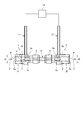
- FIG. 1 is a diagram showing an embodiment of a flow rate sensor.
- the inlet joint (inlet portion) 1 has an inner diameter d1, and a chamfer R is formed at the inflow port 1a.
- the outlet joint (outlet portion) 2 has the same inner diameter d2 as the inlet joint 1, and a chamfer R is formed at the outlet 2a.
- a cylindrical orifice portion 5 is watertightly connected between the inlet joint 1 and the outlet joint 2 by using joints 3 and 4 having a structure in which a pipe is crimped by a ferrule.
- the flow rate sensor is suitable for measuring the flow rate of gas (steam) or liquid, and is particularly suitable for measuring the flow rate of vapor.
- Arrow Y indicates the direction of fluid flow.
- the conventional "differential pressure type flow sensor” is applied in the range where the measured differential pressure is about " ⁇ 200 (mmAq)".
- a cylindrical orifice body 25 is watertightly connected between the inlet joint (inlet portion) 101 and the outlet joint (outlet portion) 102.
- Arrow Y indicates the direction of fluid flow.
- One end 25a of the orifice portion 25 is fitted to the small diameter inner peripheral portion 101e of the inlet joint 101 without a gap.
- a diameter-expanded portion 101f is formed continuously with the inner peripheral portion 101e, and an inlet pressure guiding portion 107 in an annular space is formed between the inner circumference of the enlarged diameter portion 101f and the outer circumference of one end 25a. It is formed.
- the other end 25b of the orifice portion 25 fits tightly into the small diameter inner peripheral portion 102e of the outlet joint 102.
- FIG. 5 is a sectional view taken along line VV of FIG.
- the orifice body 25 is manufactured by a sintering technique.
- the orifice body 25 is formed with m flow paths 25A, 25A, 25A, ... With the same inner diameter d penetrating in parallel in the longitudinal direction.
- the orifice body 25 is manufactured by a sintering technique, or, for example, m orifice portions having a flow path 25A can be integrally formed by press fitting or welding.
- Honeycomb pipes, deformed honeycomb pipes, and the like have been proposed as commercially available manufactured products as alternatives to the orifice body 25, and the pipes can be used.
- the length L of the orifice portion 5 when the measured flow rate is small, the required minimum cross-sectional inner diameter d of the orifice portion 5 is small. Therefore, as described above, for example, the equations (2) and (3) are used.
- the length L can be made a practical length on condition that it is satisfied.
- This other embodiment is particularly suitable for large flow rate measurement. That is, if a multiple structure is used, the orifice length L can be made a practical length.
- the orifice main body 25 satisfying the required inner diameter dm for large flow rate measurement can be configured.
- the concave groove 51 has a width wider than the width of the opening 1b communicating with the inlet pressure guiding portion 7. Although not shown, the concave groove 51 is also formed at the other end 5b. By forming the concave groove 51 at one end 5a, an inlet pressure guiding portion 7 of the annular space is formed at the inlet of the main body 50, and a surging volume is added. By forming a concave groove on the other end 5b as well, an outlet pressure guiding portion 9 of the annular space is formed at the outlet of the main body 50, and a surging volume is added. In the present embodiment, the generated differential pressure can be taken out from the inlet pressure conduit 11 and the outlet pressure conduit 13, and the flow rate can be measured with high accuracy.
- the embodiment in which a concave groove is formed at the end of the orifice portion 5 to add a surging volume can also be applied to the embodiment shown in FIG. 4, for example.
- FIG. 7 shows another embodiment.
- the same parts as those in FIG. 3 are designated by the same reference numerals, and the description thereof will be omitted.
- the main body 50 of the orifice portion 5 is fitted to the inner peripheral portion of the pipe 20 having a length L10.
- a length L near the minimum length is selected from the lengths L satisfying the above equation (2) and the above equation (3).
- one end 20a of the pipe 20 is watertightly connected to the inlet joint 1 by using a joint 3 having a ferrule structure as shown in FIG. 1, and the other end 20b is a ferrule.
- the joint 4 of the structure is watertightly connected to the outlet joint 2.
- the outer diameter D of the main body 50 is substantially equal to the inner diameter DX of the pipe 20.
- the inner diameter DX of the pipe 20 and the inner diameter d of the main body 50 have a relationship of (DX) 2 ⁇ (d) 2 .
- a flow rate sensor for steam (gas) having a "wide flow rate range (rangeability R ⁇ 100)" can measure a high-precision flow rate over the entire area, for example, with a "high differential pressure of 4000 (mmAq) FS.
- the flow rate may be measured by connecting two units of the "differential pressure sensor” and the “low differential pressure / differential pressure sensor” of 1,000 (mmAq) FS in parallel.
Landscapes
- Physics & Mathematics (AREA)
- Fluid Mechanics (AREA)
- General Physics & Mathematics (AREA)
- Measuring Volume Flow (AREA)
Priority Applications (2)
| Application Number | Priority Date | Filing Date | Title |
|---|---|---|---|
| PCT/JP2019/015399 WO2020208697A1 (ja) | 2019-04-09 | 2019-04-09 | 流量センサー |
| JP2021513054A JPWO2020208697A1 (https=) | 2019-04-09 | 2019-04-09 |
Applications Claiming Priority (1)
| Application Number | Priority Date | Filing Date | Title |
|---|---|---|---|
| PCT/JP2019/015399 WO2020208697A1 (ja) | 2019-04-09 | 2019-04-09 | 流量センサー |
Publications (1)
| Publication Number | Publication Date |
|---|---|
| WO2020208697A1 true WO2020208697A1 (ja) | 2020-10-15 |
Family
ID=72751188
Family Applications (1)
| Application Number | Title | Priority Date | Filing Date |
|---|---|---|---|
| PCT/JP2019/015399 Ceased WO2020208697A1 (ja) | 2019-04-09 | 2019-04-09 | 流量センサー |
Country Status (2)
| Country | Link |
|---|---|
| JP (1) | JPWO2020208697A1 (https=) |
| WO (1) | WO2020208697A1 (https=) |
Cited By (1)
| Publication number | Priority date | Publication date | Assignee | Title |
|---|---|---|---|---|
| US12281965B2 (en) | 2022-01-24 | 2025-04-22 | Carrier Corporation | Monitoring of an aspirating detection system |
Citations (8)
| Publication number | Priority date | Publication date | Assignee | Title |
|---|---|---|---|---|
| US3693437A (en) * | 1971-01-26 | 1972-09-26 | Kamekichi Shiba | Movable venturi type tube flow meter |
| JPS5773626U (https=) * | 1980-10-21 | 1982-05-07 | ||
| JPH05506090A (ja) * | 1989-11-06 | 1993-09-02 | バイコア モニタリング システムズ | 可変流過妨害面積ガス流量計 |
| JP2005164581A (ja) * | 2003-11-03 | 2005-06-23 | Rosemount Inc | 一体形テーパ拡径部を備えたフランジ付渦流量計 |
| JP2006308578A (ja) * | 2005-03-31 | 2006-11-09 | Nagano Keiki Co Ltd | 差圧測定用の均圧弁、および、差圧式流量計 |
| JP2006337234A (ja) * | 2005-06-03 | 2006-12-14 | Surpass Kogyo Kk | オリフィス部材、及びこれを用いた差圧流量計、流量調整装置 |
| CN105675070A (zh) * | 2016-03-28 | 2016-06-15 | 中国海洋石油总公司 | 异型文丘里流量计和用其测量多相流中气液相流量的方法 |
| WO2018232471A1 (en) * | 2017-06-23 | 2018-12-27 | Gary Stanley | A flange |
Family Cites Families (10)
| Publication number | Priority date | Publication date | Assignee | Title |
|---|---|---|---|---|
| US2942465A (en) * | 1955-02-23 | 1960-06-28 | Carbone Nettie Frishman | Fluid flow meter |
| JP2537191Y2 (ja) * | 1990-09-10 | 1997-05-28 | エスエムシー株式会社 | 差圧検出器 |
| GB2337594A (en) * | 1998-05-19 | 1999-11-24 | Abb Seatec Ltd | Flow meters using differential pressure measurements |
| JP4189070B2 (ja) * | 1998-12-07 | 2008-12-03 | 株式会社堀場エステック | マスフローメータの流量検出機構 |
| US6868741B2 (en) * | 2003-03-05 | 2005-03-22 | Veris, Inc. | Device and method enabling fluid characteristic measurement utilizing fluid acceleration |
| JP4700448B2 (ja) * | 2005-09-12 | 2011-06-15 | サーパス工業株式会社 | 差圧式流量計 |
| US7600436B2 (en) * | 2006-07-21 | 2009-10-13 | Endress + Hauser Flowtec Ag | Measuring system with a flow conditioner arranged at an inlet of a measuring tube |
| US7874208B2 (en) * | 2007-10-10 | 2011-01-25 | Brooks Instrument, Llc | System for and method of providing a wide-range flow controller |
| JP2010149919A (ja) * | 2008-12-26 | 2010-07-08 | Sapporo Breweries Ltd | 液体供給装置、液体流量計測方法及び液体量計測方法 |
| CN103591994B (zh) * | 2013-11-29 | 2016-05-11 | 湖北泽越电子科技有限公司 | 一种不受环境因素影响的高精度流量测量装置 |
-
2019
- 2019-04-09 WO PCT/JP2019/015399 patent/WO2020208697A1/ja not_active Ceased
- 2019-04-09 JP JP2021513054A patent/JPWO2020208697A1/ja active Pending
Patent Citations (8)
| Publication number | Priority date | Publication date | Assignee | Title |
|---|---|---|---|---|
| US3693437A (en) * | 1971-01-26 | 1972-09-26 | Kamekichi Shiba | Movable venturi type tube flow meter |
| JPS5773626U (https=) * | 1980-10-21 | 1982-05-07 | ||
| JPH05506090A (ja) * | 1989-11-06 | 1993-09-02 | バイコア モニタリング システムズ | 可変流過妨害面積ガス流量計 |
| JP2005164581A (ja) * | 2003-11-03 | 2005-06-23 | Rosemount Inc | 一体形テーパ拡径部を備えたフランジ付渦流量計 |
| JP2006308578A (ja) * | 2005-03-31 | 2006-11-09 | Nagano Keiki Co Ltd | 差圧測定用の均圧弁、および、差圧式流量計 |
| JP2006337234A (ja) * | 2005-06-03 | 2006-12-14 | Surpass Kogyo Kk | オリフィス部材、及びこれを用いた差圧流量計、流量調整装置 |
| CN105675070A (zh) * | 2016-03-28 | 2016-06-15 | 中国海洋石油总公司 | 异型文丘里流量计和用其测量多相流中气液相流量的方法 |
| WO2018232471A1 (en) * | 2017-06-23 | 2018-12-27 | Gary Stanley | A flange |
Cited By (1)
| Publication number | Priority date | Publication date | Assignee | Title |
|---|---|---|---|---|
| US12281965B2 (en) | 2022-01-24 | 2025-04-22 | Carrier Corporation | Monitoring of an aspirating detection system |
Also Published As
| Publication number | Publication date |
|---|---|
| JPWO2020208697A1 (https=) | 2020-10-15 |
Similar Documents
| Publication | Publication Date | Title |
|---|---|---|
| US6463810B1 (en) | Method and device for bi-directional low-velocity flow measurement | |
| CN103453959B (zh) | 微小流量传感器 | |
| US3349619A (en) | Laminar flow element and flow meter | |
| EP3132233B1 (en) | Flow meter | |
| JP4991836B2 (ja) | 流体流量計および流体ミキサ | |
| JP2005164581A (ja) | 一体形テーパ拡径部を備えたフランジ付渦流量計 | |
| JP6771254B2 (ja) | 流量計測装置及び流量計測方法 | |
| CN109738030B (zh) | 压力位差式层流流量测量方法及装置 | |
| JP2009524058A (ja) | 段付き取入口を有する縮小口径渦流量計 | |
| US7270143B2 (en) | Offset variable-orifice flow sensor | |
| US6732596B2 (en) | Critical gas flow measurement apparatus and method | |
| CN209372153U (zh) | 压力位差式层流流量测量装置 | |
| WO2020208697A1 (ja) | 流量センサー | |
| US10054472B1 (en) | Fluid flow meter | |
| JP6418936B2 (ja) | 流量計 | |
| JPH11316144A (ja) | 差圧式流量計 | |
| KR102889326B1 (ko) | 차압 기반 유량계들 (differential-pressure-based flow meters) | |
| JP5773800B2 (ja) | 圧力測定装置および圧力測定方法 | |
| US7509880B2 (en) | Fluid flow meter body with high immunity to inlet/outlet flow disturbances | |
| US10107656B1 (en) | Flow-rate measurement nozzle with velocity pressure pickup channel | |
| CN115096381B (zh) | 一种步进式流量测量传感器及应用 | |
| EP3568671B1 (en) | Fluid-flow sensor assembly having reinforced sensor body | |
| JP3122983B2 (ja) | 絞り流量計 | |
| JP3619511B2 (ja) | 流量センサ | |
| JP2582961B2 (ja) | 流量センサのバイパスユニット |
Legal Events
| Date | Code | Title | Description |
|---|---|---|---|
| 121 | Ep: the epo has been informed by wipo that ep was designated in this application |
Ref document number: 19924521 Country of ref document: EP Kind code of ref document: A1 |
|
| ENP | Entry into the national phase |
Ref document number: 2021513054 Country of ref document: JP Kind code of ref document: A |
|
| NENP | Non-entry into the national phase |
Ref country code: DE |
|
| 122 | Ep: pct application non-entry in european phase |
Ref document number: 19924521 Country of ref document: EP Kind code of ref document: A1 |