WO2020202872A1 - Dispositif de mesure de quantité physique - Google Patents
Dispositif de mesure de quantité physique Download PDFInfo
- Publication number
- WO2020202872A1 WO2020202872A1 PCT/JP2020/006709 JP2020006709W WO2020202872A1 WO 2020202872 A1 WO2020202872 A1 WO 2020202872A1 JP 2020006709 W JP2020006709 W JP 2020006709W WO 2020202872 A1 WO2020202872 A1 WO 2020202872A1
- Authority
- WO
- WIPO (PCT)
- Prior art keywords
- sensor
- measurement
- mold
- downstream
- housing
- Prior art date
Links
Images


Classifications
-
- G—PHYSICS
- G01—MEASURING; TESTING
- G01F—MEASURING VOLUME, VOLUME FLOW, MASS FLOW OR LIQUID LEVEL; METERING BY VOLUME
- G01F1/00—Measuring the volume flow or mass flow of fluid or fluent solid material wherein the fluid passes through a meter in a continuous flow
- G01F1/68—Measuring the volume flow or mass flow of fluid or fluent solid material wherein the fluid passes through a meter in a continuous flow by using thermal effects
- G01F1/684—Structural arrangements; Mounting of elements, e.g. in relation to fluid flow
- G01F1/688—Structural arrangements; Mounting of elements, e.g. in relation to fluid flow using a particular type of heating, cooling or sensing element
- G01F1/69—Structural arrangements; Mounting of elements, e.g. in relation to fluid flow using a particular type of heating, cooling or sensing element of resistive type
-
- F—MECHANICAL ENGINEERING; LIGHTING; HEATING; WEAPONS; BLASTING
- F02—COMBUSTION ENGINES; HOT-GAS OR COMBUSTION-PRODUCT ENGINE PLANTS
- F02M—SUPPLYING COMBUSTION ENGINES IN GENERAL WITH COMBUSTIBLE MIXTURES OR CONSTITUENTS THEREOF
- F02M35/00—Combustion-air cleaners, air intakes, intake silencers, or induction systems specially adapted for, or arranged on, internal-combustion engines
- F02M35/10—Air intakes; Induction systems
- F02M35/10373—Sensors for intake systems
- F02M35/10386—Sensors for intake systems for flow rate
-
- F—MECHANICAL ENGINEERING; LIGHTING; HEATING; WEAPONS; BLASTING
- F02—COMBUSTION ENGINES; HOT-GAS OR COMBUSTION-PRODUCT ENGINE PLANTS
- F02D—CONTROLLING COMBUSTION ENGINES
- F02D41/00—Electrical control of supply of combustible mixture or its constituents
- F02D41/02—Circuit arrangements for generating control signals
- F02D41/18—Circuit arrangements for generating control signals by measuring intake air flow
-
- G—PHYSICS
- G01—MEASURING; TESTING
- G01F—MEASURING VOLUME, VOLUME FLOW, MASS FLOW OR LIQUID LEVEL; METERING BY VOLUME
- G01F1/00—Measuring the volume flow or mass flow of fluid or fluent solid material wherein the fluid passes through a meter in a continuous flow
- G01F1/68—Measuring the volume flow or mass flow of fluid or fluent solid material wherein the fluid passes through a meter in a continuous flow by using thermal effects
- G01F1/684—Structural arrangements; Mounting of elements, e.g. in relation to fluid flow
- G01F1/6842—Structural arrangements; Mounting of elements, e.g. in relation to fluid flow with means for influencing the fluid flow
-
- G—PHYSICS
- G01—MEASURING; TESTING
- G01F—MEASURING VOLUME, VOLUME FLOW, MASS FLOW OR LIQUID LEVEL; METERING BY VOLUME
- G01F1/00—Measuring the volume flow or mass flow of fluid or fluent solid material wherein the fluid passes through a meter in a continuous flow
- G01F1/68—Measuring the volume flow or mass flow of fluid or fluent solid material wherein the fluid passes through a meter in a continuous flow by using thermal effects
- G01F1/684—Structural arrangements; Mounting of elements, e.g. in relation to fluid flow
- G01F1/688—Structural arrangements; Mounting of elements, e.g. in relation to fluid flow using a particular type of heating, cooling or sensing element
- G01F1/69—Structural arrangements; Mounting of elements, e.g. in relation to fluid flow using a particular type of heating, cooling or sensing element of resistive type
- G01F1/692—Thin-film arrangements
-
- G—PHYSICS
- G01—MEASURING; TESTING
- G01F—MEASURING VOLUME, VOLUME FLOW, MASS FLOW OR LIQUID LEVEL; METERING BY VOLUME
- G01F15/00—Details of, or accessories for, apparatus of groups G01F1/00 - G01F13/00 insofar as such details or appliances are not adapted to particular types of such apparatus
- G01F15/18—Supports or connecting means for meters
-
- F—MECHANICAL ENGINEERING; LIGHTING; HEATING; WEAPONS; BLASTING
- F02—COMBUSTION ENGINES; HOT-GAS OR COMBUSTION-PRODUCT ENGINE PLANTS
- F02D—CONTROLLING COMBUSTION ENGINES
- F02D41/00—Electrical control of supply of combustible mixture or its constituents
- F02D41/02—Circuit arrangements for generating control signals
- F02D41/18—Circuit arrangements for generating control signals by measuring intake air flow
- F02D41/187—Circuit arrangements for generating control signals by measuring intake air flow using a hot wire flow sensor
-
- G—PHYSICS
- G01—MEASURING; TESTING
- G01F—MEASURING VOLUME, VOLUME FLOW, MASS FLOW OR LIQUID LEVEL; METERING BY VOLUME
- G01F15/00—Details of, or accessories for, apparatus of groups G01F1/00 - G01F13/00 insofar as such details or appliances are not adapted to particular types of such apparatus
- G01F15/02—Compensating or correcting for variations in pressure, density or temperature
- G01F15/04—Compensating or correcting for variations in pressure, density or temperature of gases to be measured
-
- G—PHYSICS
- G01—MEASURING; TESTING
- G01F—MEASURING VOLUME, VOLUME FLOW, MASS FLOW OR LIQUID LEVEL; METERING BY VOLUME
- G01F15/00—Details of, or accessories for, apparatus of groups G01F1/00 - G01F13/00 insofar as such details or appliances are not adapted to particular types of such apparatus
- G01F15/06—Indicating or recording devices
- G01F15/061—Indicating or recording devices for remote indication
- G01F15/063—Indicating or recording devices for remote indication using electrical means
-
- G—PHYSICS
- G01—MEASURING; TESTING
- G01F—MEASURING VOLUME, VOLUME FLOW, MASS FLOW OR LIQUID LEVEL; METERING BY VOLUME
- G01F5/00—Measuring a proportion of the volume flow
Definitions
- This disclosure relates to a physical quantity measuring device.
- a flow rate sensor having a sensor body forming a bypass flow path and a sensor chip for detecting the flow rate of air in the bypass flow path is a flow rate measuring device. It is disclosed as.
- the sensor assembly is formed by sealing the sensor chip with a mold resin.
- the mold resin is attached to the sensor body, and the tip of the mold resin and the sensor chip are arranged in the bypass flow path.
- the sensor chip is arranged at a position separated from the fixing portion of the mold resin toward the tip end side of the mold resin.
- Patent Document 1 since the mold resin has a fixed portion, there is a concern that the fixed portion serves as a fulcrum and the relative posture of the sensor assembly with respect to the sensor body shifts when the sensor assembly is manufactured. To. In particular, in Patent Document 1, since the sensor chip is located at a position separated from the fixed portion of the mold resin toward the tip side, the portion of the fixed surface of the mold resin that serves as a fulcrum tends to be located far from the sensor chip. The posture of the sensor assembly tends to shift. If the posture of the sensor assembly shifts, the position of the sensor chip in the bypass flow path shifts, and the accuracy of flow rate detection by the sensor chip tends to decrease. As described above, if the accuracy of detecting a physical quantity such as a flow rate of a fluid such as air is lowered, the measurement accuracy of the physical quantity measuring device is lowered.
- a physical quantity such as a flow rate of a fluid such as air
- the object of the present disclosure is to provide a physical quantity measuring device capable of improving the measurement accuracy of a physical quantity.
- the physical quantity measuring device for measuring a physical quantity of a fluid includes a measurement flow path through which the fluid flows, a physical quantity sensor that detects the physical quantity of the fluid in the measurement flow path, and a sensor support unit that supports the physical quantity sensor. And a flow path housing portion that forms a measurement flow path and supports the sensor support portion.
- the sensor support portion includes a support tip portion which is one end provided in the measurement flow path, and a front fixing portion which is provided at a position separated from the support tip portion and is fixed to the inner surface of the flow path housing portion. It has a support surface, which is the surface on the exposed side of the physical quantity sensor.
- the physical quantity sensor has a sensor exposed surface exposed from the support surface.
- the front fixing base end portion which is the end portion of the front fixing portion opposite to the support tip portion, and the side opposite to the support tip portion on the sensor exposed surface.
- the distance between the exposed base end and the exposed base end is smaller than the distance between the exposed base end and the support tip.
- the exposed base end portion of the physical quantity sensor is provided at a position closer to the front fixed base end portion than the support tip portion between the front fixed base end portion and the support tip portion of the sensor support portion.
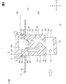
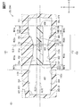
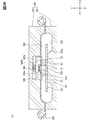
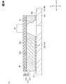
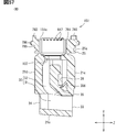
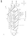
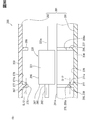
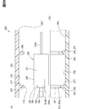
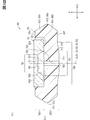
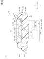
- FIG. 2 is a sectional view taken along line VIII-VIII of FIG.
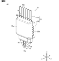
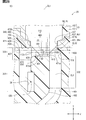
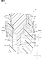
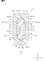
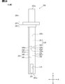
- FIG. 3 is a perspective view of the sensor SA in the configuration group A.
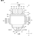
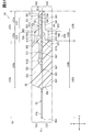
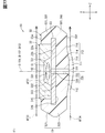
- FIG. 14 is a cross-sectional view taken along the line XV-XV of FIG.
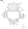
- FIG. 14 is a sectional view taken along line XVI-XVI of FIG.
- the figure which shows the state before the sensor SA deforms a housing partition part.
- FIG. 22 is a sectional view taken along line XXIV-XXIV of FIG.
- It is a vertical cross-sectional view of the air flow meter in the configuration group E, and is an enlarged view around the sensor path.
- It is a cross-sectional view of an air flow meter, and is an enlarged view around the sensor path.
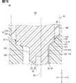
- FIG. 10 is a sectional view taken along line XXVIII-XXVIII of FIG. 10 in the configuration group F. An enlarged view of the periphery of the membrane portion of FIG. 28.
- FIG. 10 is a cross-sectional view taken along the line XXXI-XXXI of FIG. The figure for demonstrating the airflow generated in the measurement flow path.
- a cross-sectional view of a mold device showing a state before assembling the front mold portion and the back mold portion. Sectional view of the mold device. It is a vertical sectional view of the air flow meter in the configuration group G, and is the enlarged view around the front rib and the back rib.
- FIG. 35 is a cross-sectional view taken along the line XXXVI-XXXVI of FIG.
- FIG. 41 is a sectional view taken along line XLV-XLV of FIG.
- FIG. 41 is a sectional view taken along line XLVI-XLVI of FIG.
- FIG. 6 is a sectional view taken along line XLVII-XLVII of FIG.
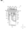
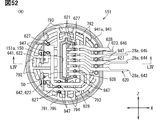
- FIG. 52 is a sectional view taken along line LIV-LIV of FIG.
- FIG. 54 is a diagram showing a first housing portion in a state where the sensor SA and the connection terminal are not mounted.
- FIG. 55 is a sectional view taken along line LVI-LVI of FIG.
- FIG. 55 is a sectional view taken along line LVII-LVII of FIG.
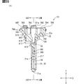
- FIG. 52 Front view of the air flow meter.
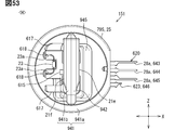
- FIG. 58 is a sectional view taken along line LX-LX of FIG.
- FIG. 60 is a sectional view taken along line LXI-LXI of FIG. 60 in the configuration group B.
- FIG. 60 is an exploded sectional view of a base member, a cover member, and a sensor SA in FIG. The enlarged view around the sensor SA of FIG. 63.
- FIG. 60 is an exploded sectional view of a base member, a cover member, and a sensor SA in FIG. The enlarged view around the sensor SA of FIG. 63.
- FIG. 3 is a vertical cross-sectional view of the air flow meter in the third embodiment, the configuration group C.
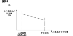
- the figure for demonstrating the cross-sectional area of an entrance passage part The figure for demonstrating the main stream which flowed into a passage flow path. The figure for demonstrating the downward drift flow which flowed into a passing flow path. The figure for demonstrating the upward drift flow which flowed into a passing flow path.
- FIG. 4 is a cross-sectional view of the vicinity of the membrane portion of the flow rate sensor in the fourth embodiment, the configuration group F.
- the figure for demonstrating the airflow generated in the measurement flow path. The vertical sectional view around the housing partition part of the air flow meter about the 1st Embodiment in the modification B1.
- the cross-sectional view around the housing partition part of the air flow meter about the 2nd Embodiment in the modification B2.
- FIG. 5 is a cross-sectional view of the periphery of the housing partition of the air flow meter for the second embodiment in the modified example B5.
- the vertical sectional view around the housing partition part of the air flow meter about the 1st Embodiment in the modification B7.
- FIG. 3 is a vertical cross-sectional view of an air flow meter around a passing flow path for the third embodiment in the modified example C1.
- FIG. 3 is a vertical cross-sectional view of an air flow meter around a passing flow path for the third embodiment in the modified example C2.
- FIG. 3 is a vertical cross-sectional view of an air flow meter around a passing flow path for the third embodiment in the modified example C3.
- the vertical sectional view of the air flow meter about the 1st Embodiment in the modification D1.
- FIG. 5 is a cross-sectional view of the air flow meter for the first embodiment in the modified example D14.
- FIG. 5 is a cross-sectional view of the vicinity of the membrane portion of the flow rate sensor for the first embodiment in the modified example F1.
- FIG. 5 is a cross-sectional view of the vicinity of the membrane portion of the flow rate sensor for the first embodiment in the modified example F2.
- FIG. 5 is a cross-sectional view of the vicinity of the membrane portion of the flow rate sensor for the first embodiment in the modified example F3.
- FIG. 5 is a cross-sectional view of the vicinity of the membrane portion of the flow rate sensor for the first embodiment in the modified example F4.
- FIG. 5 is a cross-sectional view of the vicinity of the membrane portion of the flow rate sensor for the first embodiment in the modified example F5.
- FIG. 5 is a cross-sectional view of the vicinity of the membrane portion of the flow rate sensor according to the first embodiment in the modified example F6.
- FIG. 5 is a cross-sectional view of the vicinity of the membrane portion of the flow rate sensor for the fourth embodiment in the modified example F14.
- FIG. 5 is a cross-sectional view of the vicinity of the membrane portion of the flow rate sensor for the fourth embodiment in the modified example F15.
- FIG. 5 is a cross-sectional view of the vicinity of the membrane portion of the flow rate sensor for the fourth embodiment in the modified example F16.
- FIG. 5 is a cross-sectional view of the vicinity of the membrane portion of the flow rate sensor for the fourth embodiment in the modified example F17.
- FIG. 5 is a cross-sectional view of the vicinity of the membrane portion of the flow rate sensor for the fourth embodiment in the modified example F18.
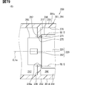
- FIG. 5 is a vertical cross-sectional view of the sensor SA for the first embodiment in the modified example G1.
- FIG. 5 is a side view of the sensor SA for the first embodiment in the modified example G3.
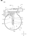
- the combustion system 10 shown in FIG. 1 includes an internal combustion engine 11 such as a gasoline engine, an intake passage 12, an exhaust passage 13, an air flow meter 20, and an ECU 15, and is mounted on, for example, a vehicle.
- the air flow meter 20 is provided in the intake passage 12 and measures physical quantities such as the flow rate, temperature, humidity, and pressure of the intake air supplied to the internal combustion engine 11.
- the air flow meter 20 is a flow rate measuring device that measures the flow rate of air, and corresponds to a physical quantity measuring device that measures a fluid such as intake air.
- the intake air is a gas supplied to the combustion chamber 11a of the internal combustion engine 11. In the combustion chamber 11a, the air-fuel mixture of the intake air and the fuel is ignited by the spark plug 17.
- the ECU (Engine Control Unit) 15 is a control device that controls the operation of the combustion system 10.
- the ECU 15 is an arithmetic processing circuit composed of a storage medium such as a processor, a RAM, a ROM, and a flash memory, a microcomputer including an input / output unit, a power supply circuit, and the like.
- Sensor signals output from the air flow meter 20 and sensor signals output from a large number of vehicle-mounted sensors are input to the ECU 15.
- the ECU 15 uses the measurement result of the air flow meter 20 to control the engine with respect to the fuel injection amount and the EGR amount of the injector 16.
- the ECU 15 is a control device that controls the operation of the internal combustion engine 11, and the combustion system 10 can also be referred to as an engine control system. Further, the ECU 15 corresponds to an external device.
- the ECU 15 may also be referred to as an electronic control unit (Electronic Control Unit).
- the control device or control system is provided by (a) an algorithm as a plurality of logics called if-then-else form, or (b) a trained model tuned by machine learning, for example, an algorithm as a neural network. ..
- the control device is provided by a control system that includes at least one computer.
- the control system may include multiple computers linked by data communication equipment.
- a computer includes at least one processor (hardware processor) which is hardware.
- the hardware processor can be provided by (i), (ii), or (iii) below.
- the hardware processor may be at least one processor core that executes a program stored in at least one memory.
- the computer is provided by at least one memory and at least one processor core.
- the processor core is called a CPU: Central Processing Unit, a GPU: Graphics Processing Unit, a RISC-CPU, or the like.
- Memory is also called a storage medium. Memory is a non-transitional and substantive storage medium that non-temporarily stores "programs and / or data" that can be read by a processor.
- the storage medium is provided by a semiconductor memory, a magnetic disk, an optical disk, or the like.
- the program may be distributed by itself or as a storage medium in which the program is stored.
- the hardware processor may be a hardware logic circuit.
- the computer is provided by a digital circuit that includes a large number of programmed logic units (gate circuits).
- the digital circuit is a logic circuit array, for example, ASIC: Application-Specific Integrated Circuit, FPGA: Field Programmable Gate Array, PGA: Programmable Gate Array, CPLD: Complex Program, etc.
- Digital circuits may include memory for storing programs and / or data.
- Computers may be provided by analog circuits. Computers may be provided by a combination of digital and analog circuits.
- the hardware processor may be a combination of the above (i) and the above (ii).
- (I) and (ii) are arranged on different chips or on a common chip. In these cases, the part (ii) is also called an accelerator.
- control device signal source, and controlled object provide various elements. At least some of those elements can be called blocks, modules, or sections. Moreover, the elements contained in the control system are called functional means only when intentionally.
- the controls and methods thereof described in this disclosure are realized by a dedicated computer provided by configuring a processor and memory programmed to perform one or more functions embodied by a computer program. May be done.
- the controls and techniques described in this disclosure may be implemented by a dedicated computer provided by configuring the processor with one or more dedicated hardware logic circuits.
- the controls and techniques described in this disclosure include a processor and memory programmed to perform one or more functions and a processor composed of one or more hardware logic circuits. It may be realized by one or more dedicated computers configured by a combination.
- the computer program may be stored in a computer-readable non-transitional tangible recording medium as an instruction executed by the computer.
- the combustion system 10 has a plurality of measuring units as an in-vehicle sensor.
- the measuring unit includes a throttle sensor 18a, an air-fuel ratio sensor 18b, and the like. All of these measuring units are electrically connected to the ECU 15 and output a detection signal to the ECU 15.
- the air flow meter 20 is provided in the intake passage 12 on the downstream side of the air cleaner 19 and on the upstream side of the throttle valve to which the throttle sensor 18a is attached.
- the air cleaner 19 has an air case forming a part of the intake passage 12 and an air filter for removing foreign matter such as dust from the intake air, and the air filter is attached to the air case.
- SENT Single Edge Nibble Transmission
- SENT communication is a kind of digital communication, and is a communication method for digitizing the measurement signal of a measuring unit such as an air flow meter 20.
- SENT communication it is possible to send measurement signals for a plurality of channels with a single electric wiring. Therefore, for example, even if the communication path that enables communication between the ECU 15 and the air flow meter 20 is formed by a single electric wiring, the time required for communication between the ECU 15 and the air flow meter 20 is unlikely to increase. It has become.
- the air flow meter 20 is attached to the piping unit 14 to be attached.
- the piping unit 14 has an intake pipe 14a, a pipe flange 14c, and a pipe boss 14d, and is a forming member that forms the intake passage 12.
- the piping unit 14 forms, for example, at least a part of an air case.
- an air filter is attached to the piping unit 14 in addition to the air flow meter 20.
- the intake pipe 14a, the pipe flange 14c, and the pipe boss 14d are formed of a resin material or the like.
- the intake pipe 14a is a pipe such as a duct forming the intake passage 12.
- the intake pipe 14a is provided with an airflow insertion hole 14b as a through hole penetrating the outer peripheral portion thereof.
- the pipe flange 14c is formed in an annular shape and extends along the peripheral edge of the airflow insertion hole 14b.
- the pipe flange 14c extends from the outer surface of the intake pipe 14a toward the side opposite to the intake passage 12.
- the pipe boss 14d is a columnar member and is a support portion that supports the air flow meter 20.
- a plurality (for example, two) of pipe bosses 14d extend from the outer surface of the intake pipe 14a along the pipe flange 14c and are provided with respect to the intake pipe 14a. In the present embodiment, both the pipe flange 14c and the pipe boss 14d extend from the intake pipe 14a in the height direction Y.
- the air flow meter 20 has entered the intake passage 12 by being inserted into the pipe flange 14c and the air flow insertion hole 14b, and is fixed to the pipe boss 14d by a fixture such as a bolt in this state.
- the air flow meter 20 is not in contact with the tip surface of the pipe flange 14c, but is in contact with the tip surface of the pipe boss 14d. Therefore, the relative position and angle of the air flow meter 20 with respect to the piping unit 14 are set by the pipe boss 14d instead of the pipe flange 14c.
- the tip surfaces of the plurality of tube bosses 14d are flush with each other. In FIG. 8, the tube boss 14d is not shown.
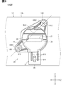
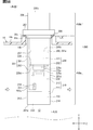
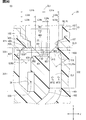
- the width direction X, the height direction Y, and the depth direction Z are set for the air flow meter 20, and these directions X, Y, and Z are orthogonal to each other.
- the air flow meter 20 extends in the height direction Y, and the intake passage 12 extends in the depth direction Z.
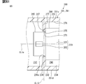
- the air flow meter 20 has an entry portion 20a that has entered the intake passage 12 and a protruding portion 20b that protrudes to the outside from the pipe flange 14c without entering the intake passage 12, and the entry portion 20a and the protrusion portion 20b. Are lined up in the height direction Y.
- the air flow meter 20 includes a housing 21, a flow rate sensor 22 that detects the flow rate of intake air, and an intake air temperature sensor 23 that detects the temperature of intake air.
- the housing 21 is made of, for example, a resin material.
- the flow rate sensor 22 is housed inside the housing 21. In the air flow meter 20, the housing 21 is attached to the intake pipe 14a so that the flow rate sensor 22 can come into contact with the intake air flowing through the intake passage 12.
- the housing 21 is attached to the piping unit 14 to be attached.
- the housing tip surface 21a On the outer surface of the housing 21, of the pair of end faces 21a and 21b arranged in the height direction Y, the one included in the intruding portion 20a is referred to as the housing tip surface 21a, and the one included in the protruding portion 20b is the housing base. It is referred to as an end face 21b.
- the housing tip surface 21a and the housing base end surface 21b are orthogonal to the height direction Y.
- the tip surface of the pipe flange 14c is also orthogonal to the height direction Y.
- the attachment target to which the air flow meter 20 and the housing 21 are attached does not have to be the piping unit 14 as long as it is a forming member forming the intake passage 12.
- the surface arranged on the upstream side of the intake passage 12 is referred to as the housing upstream surface 21c, and the surface arranged on the side opposite to the housing upstream surface 21c is referred to as the housing downstream surface 21d.
- the housing surface 21e one of the pair of surfaces facing each other via the housing upstream surface 21c and the housing base end surface 21b is referred to as a housing surface 21e, and the other is referred to as a housing back surface 21f.
- the housing surface 21e is a surface on the side where the flow rate sensor 22 is provided in the sensor SA50 described later.
- the housing front end surface 21a side may be referred to as the housing front end side
- the housing base end surface 21b side may be referred to as the housing base end side
- the housing upstream surface 21c side may be referred to as the housing upstream side
- the housing downstream surface 21d side may be referred to as the housing downstream side
- the housing front surface 21e side may be referred to as the housing front side
- the housing back surface 21f side may be referred to as the housing back side.
- the housing 21 has a seal holding portion 25, a flange portion 27, and a connector portion 28.
- the air flow meter 20 has a seal member 26, and the seal member 26 is attached to the seal holding portion 25.
- the seal holding portion 25 is provided inside the pipe flange 14c, and holds the seal member 26 so as not to be displaced in the height direction Y.
- the seal holding portion 25 is included in the entry portion 20a of the air flow meter 20.
- the seal holding portion 25 has a holding groove portion 25a for holding the seal member 26.
- the holding groove portion 25a extends in directions X and Z orthogonal to the height direction Y, and goes around the housing 21 in an annular shape.
- the seal member 26 is a member such as an O-ring that seals the intake passage 12 inside the pipe flange 14c.
- the seal member 26 is in a state of being inserted into the holding groove portion 25a, and is in close contact with both the inner surface of the holding groove portion 25a and the inner peripheral surface of the pipe flange 14c.
- the portion where the seal member 26 and the inner surface of the holding groove portion 25a are in close contact with each other and the portion where the seal member 26 and the inner peripheral surface of the pipe flange 14c are in close contact both circulate in an annular shape around the housing 21.
- the flange portion 27 is formed with fixing holes such as screw holes for fixing fixtures such as screws for fixing the housing 21 to the intake pipe 14a.
- the fixing holes are, for example, flange holes 611 and 612, and the fixing tool is a screw. In FIG. 3, the screws inserted through the flange holes 611 and 612 are not shown.
- the surface on the tip side of the housing is in contact with the tip surface of the pipe boss 14d in a state of being overlapped, and this overlapped portion is referred to as an angle setting surface 27a.
- Both the angle setting surface 27a and the tip surface of the pipe boss 14d extend in a direction orthogonal to the height direction Y, and extend in the width direction X and the depth direction Z.
- the tip surface of the pipe boss 14d sets the relative position and angle of the angle setting surface 27a with respect to the intake pipe 14a.
- the angle setting surface 27a sets the relative position and angle of the housing 21 with respect to the intake pipe 14a in the air flow meter 20.
- the main flow of the air flowing through the intake passage 12 mainly flows in the depth direction Z.
- the depth direction Z is the mainstream direction.
- the angle setting surface 27a of the flange portion 27 extends in the mainstream direction and the depth direction Z.
- the tip surface of the pipe boss 14d also extends in the mainstream direction and the depth direction Z.
- the connector unit 28 is a protective unit that protects the connector terminal 28a electrically connected to the flow sensor 22.
- the connector terminal 28a is electrically connected to the ECU 15 by connecting the electrical wiring extending from the ECU 15 to the connector portion 28 via the plug portion.
- the flange portion 27 and the connector portion 28 are included in the protruding portion 20b of the air flow meter 20.
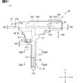
- the intake air temperature sensor 23 is provided on the outside of the housing 21.
- the intake air temperature sensor 23 is a temperature-sensitive element that senses the temperature of the intake air, and is provided on the back surface 21f side of the housing.
- a lead wire 23a formed by wiring or the like is connected to the intake air temperature sensor 23.
- the housing 21 has a lead support portion 618.
- the lead support portion 618 is a convex portion provided on the back surface 21f of the housing, and protrudes toward the back side of the housing from the intake air temperature sensor 23 in the width direction X.
- the lead support portion 618 supports the intake air temperature sensor 23 by supporting the lead wire 23a.
- the lead support portion 618 is provided on the base end side of the housing with respect to the intake air temperature sensor 23 in the height direction Y.
- the lead wire 23a extends from the lead support portion 618 toward the tip end side of the housing.
- the lead wire 23a penetrates the lead support portion 618 in the height direction Y.
- a through hole is formed in the lead support portion 618 so as to penetrate the lead support portion 618 in the height direction Y.
- the lead support portion 618 is crushed in the width direction X to crush the through hole, and the lead wire 23a inserted through the through hole is passed through the lead support portion 618.
- the lead support portion 618 is thermally deformed by crushing the tip surface of the lead support portion 618 while heating it with a heating tool such as a heater, and the lead wire 23a is covered with the thermally deformed portion of the lead support portion 618. Hold on. This work can also be referred to as heat caulking.
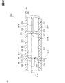
- the housing 21 has a bypass flow path 30.
- the bypass flow path 30 is provided inside the housing 21 and is formed by at least a part of the internal space of the housing 21.
- the inner surface of the housing 21 forms a bypass flow path 30 and is a forming surface.
- the bypass flow path 30 is arranged in the entry portion 20a of the air flow meter 20.
- the bypass flow path 30 has a pass flow path 31 and a measurement flow path 32.
- the flow rate sensor 22 and the surrounding portion of the sensor SA50, which will be described later, are in the measurement flow path 32.
- the passage path 31 is formed by the inner surface of the housing 21.
- the measurement flow path 32 is formed by a part of the outer surface of the sensor SA50 in addition to the inner surface of the housing 21.
- the intake passage 12 may be referred to as a main passage, and the bypass passage 30 may be referred to as a sub passage.
- the passing flow path 31 penetrates the housing 21 in the depth direction Z.
- the passage passage 31 has a passage inlet 33 which is an upstream end portion thereof and a passage outlet 34 which is a downstream end portion thereof.
- the measurement flow path 32 is a branch flow path branched from the intermediate portion of the pass flow path 31, and the flow rate sensor 22 is provided in the measurement flow path 32.
- the measurement flow path 32 has a measurement inlet 35 which is an upstream end portion thereof and a measurement outlet 36 which is a downstream end portion thereof.
- the portion where the measurement flow path 32 branches from the pass flow path 31 is a boundary portion between the pass flow path 31 and the measurement flow path 32, and the measurement inlet 35 is included in this boundary portion. Further, the boundary portion between the passing flow path 31 and the measuring flow path 32 can also be referred to as a flow path boundary portion.
- the measurement inlet 35 faces the housing tip side in a state of being inclined so as to face the measurement outlet 36 side.
- the measurement flow path 32 extends from the pass flow path 31 toward the base end side of the housing.
- the measuring flow path 32 is provided between the passing flow path 31 and the housing base end surface 21b.
- the measurement flow path 32 is bent so that the portion between the measurement inlet 35 and the measurement outlet 36 bulges toward the base end side of the housing.
- the measurement flow path 32 has a portion curved so as to be continuously bent, a portion bent so as to be bent stepwise, a portion extending straight in the height direction Y and the depth direction Z, and the like.
- the flow rate sensor 22 is a thermal type flow rate detection unit having a heater unit.
- the flow rate sensor 22 outputs a detection signal corresponding to the temperature change when the temperature changes due to the heat generated by the heater unit.
- the flow rate sensor 22 is a rectangular parallelepiped chip component, and the flow rate sensor 22 can also be referred to as a sensor chip.
- the sensor SA is attached to the housing 21 in a state where the entire flow rate sensor 22 is housed in the measurement flow path 32. As long as the flow rate sensor 22 can detect the flow rate in the measurement flow path 32, a part of the flow rate sensor 22 may be housed in the measurement flow path 32.
- the flow rate sensor 22 is provided in the measurement flow path 32. Further, the flow rate sensor 22 can also be referred to as a physical quantity sensor or a physical quantity detecting unit that detects the flow rate of the intake air as a physical quantity of the fluid.
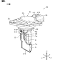
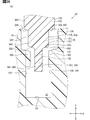
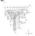
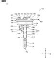
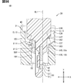
- the air flow meter 20 has a sensor sub-assembly including a flow rate sensor 22, and this sensor sub-assembly is referred to as a sensor SA50.
- the sensor SA50 is embedded inside the housing 21 in a state where a part of the sensor SA50 is inserted into the measurement flow path 32.
- the sensor SA50 and the bypass flow path 30 are arranged in the height direction Y.
- the sensor SA50 and the passing flow path 31 are arranged in the height direction.
- the sensor SA50 corresponds to the detection unit. Further, the sensor SA50 can also be referred to as a measurement unit or a sensor package.
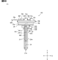
- the sensor SA50 has a sensor support portion 51 in addition to the flow rate sensor 22.
- the sensor support portion 51 is attached to the housing 21 and supports the flow rate sensor 22.
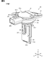
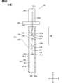
- the sensor support portion 51 has an SA substrate 53 and a mold portion 55.
- the SA substrate 53 is a substrate on which the flow rate sensor 22 is mounted, and the mold portion 55 covers at least a part of the flow rate sensor 22 and at least a part of the SA substrate 53.
- the SA substrate 53 can also be referred to as a lead frame.
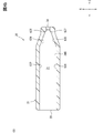
- the mold portion 55 is formed in a plate shape as a whole.
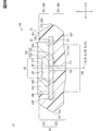
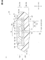
- the housing tip side On the outer surface of the mold portion 55, of the pair of end faces 55a and 55b arranged in the height direction Y, the housing tip side is referred to as the mold tip surface 55a, and the housing base end side is referred to as the mold base end face 55b. ..
- the mold tip surface 55a is the tip of the mold portion 55 and the sensor support portion 51, and corresponds to the support tip portion. Further, the mold portion 55 corresponds to the protective resin portion.
- the mold upstream surface 55c On the outer surface of the mold portion 55, one of the pair of surfaces provided with the mold tip surface 55a and the mold base end surface 55b sandwiched therein is referred to as a mold upstream surface 55c, and the other is referred to as a mold downstream surface 55d.
- the sensor SA50 is inside the housing 21 with the mold tip surface 55a arranged on the airflow tip side and the mold upstream surface 55c arranged on the upstream side of the measurement flow path 32 with respect to the mold downstream surface 55d. It is installed in.
- the mold upstream surface 55c corresponds to the upstream end portion
- the mold downstream surface 55d corresponds to the downstream end portion.
- the mold upstream surface 55c of the sensor SA50 is arranged on the upstream side of the mold downstream surface 55d in the measurement flow path 32.
- the direction of air flow is opposite to the direction of air flow in the intake passage 12. Therefore, the mold upstream surface 55c is arranged on the downstream side of the mold downstream surface 55d in the intake passage 12.
- the air flowing along the flow rate sensor 22 flows in the depth direction Z, and this depth direction Z can also be referred to as a flow direction.
- the flow rate sensor 22 is exposed on one side of the sensor SA50.
- the mold surface 55e On the outer surface of the mold portion 55, the plate surface on the side where the flow sensor 22 is exposed is referred to as the mold surface 55e, and the plate surface on the opposite side is referred to as the mold back surface 55f.
- One plate surface of the sensor SA50 is formed by the mold surface 55e, the mold surface 55e corresponds to the support surface, and the mold back surface 55f corresponds to the support back surface.
- the mold tip surface 55a side may be referred to as the mold side
- the mold base end surface 55b side may be referred to as the mold base end side.
- the mold upstream surface 55c side may be referred to as the mold upstream side
- the mold downstream surface 55d side may be referred to as the mold downstream side.
- the mold front surface 55e side may be referred to as the mold front side
- the mold back surface 55f side may be referred to as the mold back side.
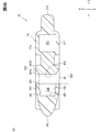
- the sensor SA50 has a peripheral recess 56.
- the peripheral edge recess 56 is an elongated recess provided on the mold surface 55e, and extends in a groove shape along the peripheral edge of the flow sensor 22.
- the bottom surface of the peripheral recess 56 is provided at a position separated from the mold surface 55e on the back side of the mold, and is formed by the mold portion 55.
- the pair of inner wall surfaces of the peripheral recess 56 face each other via the bottom surface, the inner wall surface on the inner peripheral side is formed by the outer wall surface of the flow rate sensor 22, and the inner wall surface on the outer peripheral side is formed by the mold portion 55. ..
- the depth dimension in the width direction X is smaller than the width dimension in the directions Y and Z orthogonal to the width direction X.
- the peripheral recess 56 is provided on the mold tip side with respect to the table measurement step surface 555 described later.
- the peripheral recess 56 has a pair of vertical portions extending parallel to each other in the height direction Y and a horizontal portion extending in the depth direction Z so as to connect these vertical portions, and the pair of vertical portions are measured in a table. It extends from the stepped surface 555 toward the tip of the mold.
- the peripheral edge recess 56 is provided at a position separated inward from the outer peripheral edge of the mold surface 55e in the directions Y and Z orthogonal to the width direction X.
- the flow rate sensor 22 is provided at a position separated from the mold surface 55e on the mold back side in the width direction X.
- the sensor surface 22a which will be described later, is provided at a position on the back side of the mold with respect to the mold surface 55e.
- the bottom surface of the peripheral recess 56 extends parallel to the sensor surface 22a in the directions Y and Z orthogonal to the width direction X. In this case, in the peripheral recess 56, the height dimension of the inner wall surface on the inner peripheral side from the bottom surface is smaller than the height dimension of the inner wall surface on the outer peripheral side from the bottom surface in the width direction X (see FIG. 34). ).
- the SA substrate 53 is a conductive substrate that is formed in a plate shape as a whole with a metal material or the like.
- the plate surface of the SA substrate 53 is orthogonal to the width direction X and extends in the height direction Y and the depth direction Z.
- the flow rate sensor 22 is mounted on the SA board 53.
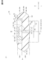
- the SA board 53 has a lead terminal 53a, an upstream test terminal 53b, and a downstream test terminal 53c.
- the SA substrate 53 has a portion covered by the mold portion 55 and a portion not covered by the mold portion 55, and terminals 53a, 53b, and 53c are formed by the uncovered portions. .. In FIG. 8 and the like, the terminals 53a, 53b, and 53c are not shown.
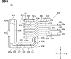
- the lead terminals 53a are terminals protruding in the height direction Y from the mold base end surface 55b, and a plurality of lead terminals 53a are provided.
- the plurality of lead terminals 53a include terminals 671 to 673 connected to the connector terminals 28a, terminals 674 and 675 connected to the intake air temperature sensor 23, and adjustment terminals 676 for adjusting the detection accuracy of the flow rate sensor 22. include.
- the sensor SA50 has six lead terminals 53a. These six lead terminals 53a include three terminals connected to the connector terminal 28a, two terminals connected to the intake air temperature sensor 23, and one adjustment terminal. To the three terminals connected to the connector terminal 28a, a flow rate ground terminal 671 grounded to the ground, a flow rate power supply terminal 672 to which a predetermined voltage such as 5V is applied, and a signal relating to the detection result of the flow rate sensor 22 are output. A flow rate output terminal 673 is included.
- the two terminals connected to the intake air temperature sensor 23 include an intake air temperature ground terminal 674 connected to the ground and an intake air temperature output terminal 675 that outputs a signal related to the detection result of the intake air temperature sensor 23.
- terminals 671 to 676 are arranged in the depth direction Z.
- the flow rate measuring terminals 671 to 673 are arranged between the intake air temperature measuring terminals 674 and 675 and the adjusting terminal 676.
- the flow rate ground terminal 671 is arranged between the flow rate power supply terminal 672 and the flow rate output terminal 673.
- the flow rate power supply terminal 672 is arranged next to the adjustment terminal 676, and the flow rate output terminal 673 is arranged next to the intake air temperature ground terminal 674.
- the order of the terminals 671 to 676 does not have to be the above-mentioned order.
- a communication path for performing SENT communication is formed by a flow rate output terminal 673 and an intake air temperature output terminal 675.
- SENT communication for flow rate measurement is performed through the flow rate output terminal 673
- SENT communication for intake air temperature measurement is performed through the intake air temperature output terminal 675.
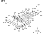
- the downstream test terminals 53c are terminals protruding in the depth direction Z from the mold downstream surface 55d, and a plurality of them are provided.
- the plurality of downstream test terminals 53c include IC test terminals 691, 692, capacitor check terminals 693, 694, and ground terminals 695, 696.
- the IC test terminals 691, 692 are terminals for checking the operation of the flow rate sensor 22 and the like.
- the capacitor check terminals 693 and 694 are terminals for checking the operation of the internal capacitor mounted on the SA board 53.
- Ground terminals 695 and 696 are terminals for grounding to the ground.
- terminals 691 to 696 are arranged in the height direction Y.
- one ground terminal 695 is arranged between the IC test terminals 691,692 and the capacitor check terminals 693 and 694.
- the other ground terminal 696 is arranged on the opposite side of the one ground terminal 695 via the capacitor check terminals 693 and 694.
- One of the ground terminals 695 and 696 is shorter than the other.
- the ground terminal 696 is shorter than the ground terminal 695.
- the ground terminal 696 is shorter than the IC test terminals 691,692 and the capacitor check terminals 693 and 694.
- the upstream test terminals 53b are terminals protruding in the depth direction Z from the mold upstream surface 55c, and a plurality of upstream test terminals 53b are provided.
- the plurality of upstream test terminals 53b include IC test terminals 681 and 682, capacitor check terminals 683 and 684, and ground terminals 685.
- the IC test terminals 681 and 682 are terminals for checking the operation of the flow rate sensor 22 and the like.
- the capacitor check terminals 683 and 684 are terminals for checking the operation of the internal capacitor.
- the ground terminal 685 is a terminal for grounding to the ground.
- terminals 681 to 685 are arranged in the height direction Y.
- capacitor check terminals 683 and 684 are arranged between the IC test terminals 681 and 682 and the ground terminal 685.
- the ground terminal 685 is short like the upstream ground terminal 696, and is shorter than the IC test terminals 681 and 682 and the capacitor check terminals 683 and 684.
- the test terminals 53b and 53c are not in contact with the inner surface of the first housing portion 151.
- the ground terminal 685 is shorter than the other terminals 681 to 684 as described above. Therefore, although the ground terminal 685 is arranged at the position closest to the tip of the housing among the terminals 681 to 685, the housing step surface 137 (see FIG. 17) described later inside the first housing portion 151 (see FIG. 17). It is difficult to contact with.
- the ground terminal 696 is shorter than the other terminals 691 to 695 as described above. Therefore, although the ground terminal 696 is arranged at the position closest to the tip of the housing among the terminals 691 to 695, it is difficult to come into contact with the step surface 137 of the housing inside the first housing portion 151. ..
- the lead terminal 53a is provided with a lead hole 54.
- the lead hole 54 penetrates the lead terminal 53a in the thickness direction of the lead terminal 53a, and is provided in each of the lead terminals 53a.
- the lead hole 54 is arranged at a position closer to the mold portion 55 at the lead terminal 53a in the height direction Y.
- the manufacturing process of the air flow meter 20 includes an inspection step of the flow rate sensor 22 at a stage after manufacturing the flow rate sensor 22 and before assembling the flow rate sensor 22 to the first housing portion 151. In this inspection step, work for confirming that the flow rate sensor 22 operates normally, work for acquiring the detection accuracy of the flow rate sensor 22, and work for adjusting the detection accuracy of the flow rate sensor 22 are performed.
- the flow rate sensor 22 is inspected with the flow rate sensor 22 fixed to the workbench.
- the workbench is provided with a jig for positioning a pin or the like, and the flow sensor 22 is positioned with respect to the workbench by inserting the jig into the lead hole 54.
- the work load when fixing the flow rate sensor 22 to the workbench so as not to shift the position is reduced.
- the flow rate ground terminal 671 and the intake air temperature ground terminal 674 are integrally provided in the processing mounting portion 882 (see FIG. 37), while the other terminals 672, 673, 675, 676 are processed. It is provided independently of the mounting unit 882.
- the ground terminal 685 is integrally provided with the processing mounting portion 882, while the other terminals 681 to 684 are provided independently of the processing mounting portion 882.
- the ground terminals 695 and 696 are integrally provided in the processing mounting portion 882, while the other terminals 691 to 694 are provided in a state independent of the processing mounting portion 882. In this way, the ground terminals 671,674,685,695,696 are connected to each other via the processing mounting unit 882.
- At least one terminal is shortened in each of the upstream test terminal 53b and the downstream test terminal 53c.
- a plurality of terminals counting from the housing tip side may be shorter than the terminals arranged at the position closest to the housing base end side. In this case, it is possible to more reliably avoid the terminals 681 to 685 coming into contact with the inner surface of the housing 21.
- the outer surface of the SA substrate 53 includes a reference surface and a rough surface.
- the rough surface is a surface that is rougher than the reference surface because, for example, a large number of small protrusions and recesses of 0.5 to 1.0 ⁇ m are provided.
- the outer surface of the lead terminal 53a is a reference surface, and the outer surface of other parts is a rough surface.
- the rough surface of the SA substrate 53 includes a portion embedded inside the mold portion 55 and test terminals 53b and 53c. The surface area of the rough surface is larger than that of the reference surface, so that the resin can easily adhere to the rough surface.
- the outer surface of the lead terminal 53a is a smoother reference surface than the rough surface. For this reason, the contact area between the plate surface of the lead terminal 53a and the plate surface of the lead connection terminal 621 tends to be large, so that the electrical resistance at the connection portion between the lead terminal 53a and the lead connection terminal 621 becomes small. Cheap. Further, it is easy to facilitate the welding work between the lead terminal 53a and the lead connection terminal 621.
- the flow rate sensor 22 is formed in a plate shape as a whole.
- the flow rate sensor 22 has a sensor surface 22a on one side and a sensor back surface 22b opposite to the sensor surface 22a.
- the back surface 22b of the sensor is overlapped with the SA substrate 53, and a part of the sensor surface 22a is exposed to the outside of the sensor SA50.
- the flow rate sensor 22 has a sensor recess 61 and a membrane portion 62.
- the sensor recess 61 is provided on the back surface 22b of the sensor, and the membrane portion 62 is provided on the front surface 22a of the sensor.
- the membrane portion 62 forms the sensor concave bottom surface 501, which is the bottom surface of the sensor recess 61.
- the portion of the membrane portion 62 forming the sensor concave bottom surface 501 is the bottom portion for the sensor concave bottom 61.
- the sensor recess 61 is formed by denting the back surface 22b of the sensor toward the front surface 22a of the sensor, and is a cavity provided in the back surface 22b of the sensor.
- the membrane unit 62 is a sensing unit that senses the flow rate.
- the flow rate sensor 22 has a sensor substrate 65 and a sensor film portion 66.
- the sensor substrate 65 is a base material of the flow rate sensor 22, and is formed in a plate shape by a semiconductor material such as silicon.
- the sensor substrate 65 has one surface, a sensor substrate surface 65a, and a sensor substrate back surface 65b opposite to the sensor substrate surface 65a.
- the sensor substrate 65 is formed with a through hole that penetrates the sensor substrate 65 in the width direction X, and the sensor recess 61 is formed by the through hole.
- the sensor substrate 65 may be formed with a recess for forming the sensor recess 61 instead of a through hole. In this case, the bottom surface of the sensor recess 61 is not formed by the membrane portion 62, but is formed by the bottom surface of the recess of the sensor substrate 65.
- the sensor film portion 66 is overlapped with the sensor substrate surface 65a of the sensor substrate 65, and extends in a film shape along the sensor substrate surface 65a.
- the sensor front surface 22a is formed by the sensor film portion 66
- the sensor back surface 22b is formed by the sensor substrate 65.
- the back surface 22b of the sensor is the back surface 65b of the sensor substrate 65 of the sensor substrate 65.
- the sensor film portion 66 covers the through hole of the sensor substrate 65, and the portion of the sensor film portion 66 that covers the through hole is the membrane portion 62.
- the bottom surface 501 of the sensor recess is formed by the back surface of the sensor film portion 66.
- the sensor film unit 66 has a plurality of layers such as an insulating layer, a conductive layer, and a protective layer, and has a multi-layer structure. All of these are formed in a film shape and extend along the sensor substrate surface 65a.
- the sensor film portion 66 has a wiring pattern such as wiring and a resistor, and this wiring pattern is formed by a conductive layer.
- the sensor recess 61 is formed by processing a part of the sensor substrate 65 by wet etching.
- a mask such as a silicon nitride film is attached to the back surface 65b of the sensor substrate 65, and is different from the back surface 65b of the sensor substrate until the sensor film portion 66 is exposed using an etching solution. Perform sex etching.
- the sensor recess 61 may be formed by performing dry etching on the sensor substrate 65.
- the sensor SA50 has a flow rate detection circuit that detects the flow rate of air, and at least a part of the flow rate detection circuit is included in the flow rate sensor 22.
- the sensor SA50 has a heat generating resistor 71, a resistance temperature detector 72, 73, and an indirect thermal resistor 74 as circuit elements included in the flow rate detection circuit.
- These resistors 71 to 74 are included in the flow rate sensor 22 and are formed by the conductive layer of the sensor film portion 66.
- the sensor film portion 66 has resistors 71 to 74, and these resistors 71 to 74 are included in the wiring pattern of the conductive layer. Resistors 71 to 74 correspond to detection elements.
- the wiring pattern including the resistors 71 to 74 is shown by dot hatching.
- the flow rate detection circuit can also be referred to as a flow rate measuring unit that measures the flow rate of air.
- the heat generation resistor 71 is a resistance element that generates heat when the heat generation resistor 71 is energized.
- the heat generation resistor 71 heats the sensor film portion 66 by generating heat, and corresponds to a heater portion.
- the resistance temperature detectors 72 and 73 are resistance elements for detecting the temperature of the sensor film unit 66, and correspond to the temperature detection unit. The resistance values of the resistance temperature detectors 72 and 73 change according to the temperature of the sensor film unit 66. In the flow rate detection circuit, the temperature of the sensor film unit 66 is detected using the resistance values of the resistance temperature detectors 72 and 73.
- the flow rate detection circuit raises the temperature of the sensor film portion 66 and the resistance temperature detectors 72, 73 by the heat generating resistor 71, and when an air flow occurs in the measurement flow path 32, the resistance temperature detectors 72, 73 The air flow rate and the direction of the flow are detected by using the change mode of the detection temperature according to.
- the heat generating resistor 71 is arranged substantially in the center of the membrane portion 62 in each of the height direction Y and the depth direction Z.
- the heat generating resistor 71 is formed in a rectangular shape extending in the height direction Y as a whole.
- the center line CL1 of the heat generation resistor 71 passes through the center CO1 of the heat generation resistor 71 and extends linearly in the height direction Y. This center line CL1 passes through the center of the membrane portion 62.
- the heat generation resistor 71 is arranged at a position separated inward from the peripheral edge portion of the membrane portion 62. In the heat generating resistor 71, the separation distance from the center CO1 is the same at the end on the mold tip side and the end on the mold base end side.
- the resistance temperature detectors 72 and 73 are all formed in a rectangular shape extending in the height direction Y as a whole, and are arranged in the depth direction Z.
- a heat generating resistor 71 is provided between the resistance temperature detectors 72 and 73.
- the upstream resistance temperature detector 72 is provided at a position separated from the heat generation resistor 71 on the upstream side of the mold.
- the downstream resistance temperature detector 73 is provided at a position separated from the heat generating resistor 71 on the downstream side of the mold.
- the center line CL2 of the upstream resistance temperature detector 72 and the center line CL3 of the downstream resistance temperature detector 73 both extend linearly in parallel with the center line CL1 of the heat generating resistor 71.
- the heat generation resistor 71 is provided at an intermediate position between the upstream resistance temperature detector 72 and the downstream resistance temperature detector 73 in the depth direction Z.
- the mold upstream surface 55c side is referred to as the mold upstream side
- the mold downstream surface 55d side is referred to as the mold downstream side
- the mold tip surface 55a side is referred to as a mold tip side
- the mold base end surface 55b side is referred to as a mold base end side.
- the indirect thermal resistor 74 is a resistance element for detecting the temperature of the heat generating resistor 71.
- the indirect thermal resistor 74 extends along the peripheral edge of the heat generating resistor 71.
- the resistance value of the indirect thermal resistor 74 changes according to the temperature of the heating resistor 71.
- the temperature of the heat generating resistor 71 is detected by using the resistance value of the indirect thermal resistor 74.
- the sensor SA50 has a heat generating wiring 75 and a temperature measuring wiring 76, 77. These wirings 75 to 77 are included in the wiring pattern of the sensor film unit 66, similarly to the resistors 71 to 74.
- the heat generation wiring 75 extends from the heat generation resistor 71 toward the mold base end side in the height direction Y.
- the upstream temperature measurement wiring 76 extends from the upstream resistance temperature detector 72 toward the mold tip side in the height direction Y.
- the downstream temperature measuring wiring 77 extends from the downstream temperature measuring resistor 73 toward the tip end side of the mold in the height direction Y.
- an internal capacitor is mounted on the SA board 53.
- the sensor SA50 has an internal power supply that applies a constant voltage to a bridge circuit or the like included in the flow rate detection circuit, and the internal capacitor has a function of stabilizing the voltage of the internal power supply.
- the internal capacitor is a passive component such as a chip capacitor.
- the internal capacitor has an immunity resistance function for the sensor SA50 to withstand external noise, an emission reduction function for reducing the internal noise from the sensor SA50, and a static electricity resistance function for the sensor SA50 to withstand static electricity. ..
- heater temperature control such as feedback control is performed in order to adjust the temperature of the heat generated by the heat generating resistor 71.
- the internal capacitor has a function of regulating the on-state and the off-state of the heating resistor 71 from oscillating in the heater temperature control. In this case, the heater temperature control is stabilized by the internal capacitor.
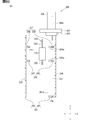
- the center line CL4 of the measurement flow path 32 passes through the center CO2 of the measurement inlet 35 and the center CO3 of the measurement outlet 36, and extends linearly along the measurement flow path 32. ..
- the sensor SA50 is provided between the measurement inlet 35 and the measurement outlet 36 in the measurement flow path 32.
- the sensor SA50 is provided at a position separated from the measurement inlet 35 on the upstream side and at a position separated from the measurement outlet 36 on the upstream side.
- the center line of the region of the measurement flow path 32 excluding the internal space of the SA insertion hole 107 is shown as the center line CL4.
- both the passing inlet 33 and the passing exit 34 are rectangular and vertically elongated.
- the height dimension in the height direction Y is larger than the width dimension in the width direction X.
- the opening area of the passing outlet 34 is smaller than the opening area of the passing inlet 33.
- the opening area of the passing outlet 34 is smaller than 1/2 of the opening area of the passing inlet 33.
- the height dimension of the passing outlet 34 and the height dimension of the passing inlet 33 are the same, while in the width direction X, the width dimension of the passing outlet 34 is smaller than the width dimension of the passing inlet 33.
- the opening area of the passing inlet 33 is the area of the region including the central CO21 of the passing inlet 33
- the opening area of the passing outlet 34 is the area of the region including the central CO24 of the passing outlet 34.
- the center of the passage inlet 33 is arranged at a position overlapping the center line of the intake passage 12.
- the width dimension of the passage inlet 33 is set to a value as small as possible so that the pressure loss generated in the bypass flow path 30 does not become too large.
- the width dimension of the passage inlet 33 is set so that the pressure loss in the bypass flow path 30 and the robustness of measurement are optimized.
- the measurement outlet 36 has a rectangular shape and a vertically long shape.
- the height dimension in the height direction Y is larger than the width dimension in the width direction X.
- the opening area of the measurement outlet 36 is smaller than the opening area of the measurement inlet 35.
- the total value of the opening areas of the plurality of measurement outlets 36 is larger than the opening area of the measurement inlet 35.
- the opening area of the measurement inlet 35 is the area of the region including the central CO2 of the measurement inlet 35
- the opening area of the measurement outlet 36 is the area of the region including the center CO3 of the measurement outlet 36.
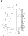
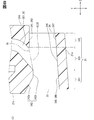
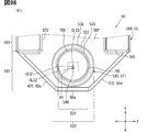
- the housing 21 has a measurement floor surface 101, a measurement ceiling surface 102, a front measurement wall surface 103, and a back measurement wall surface 104 as forming surfaces forming the measurement flow path 32.
- the measurement floor surface 101, the measurement ceiling surface 102, the front measurement wall surface 103, and the back measurement wall surface 104 all extend along the center line CL4 of the measurement flow path 32.
- the measurement floor surface 101, the measurement ceiling surface 102, the front measurement wall surface 103, and the back measurement wall surface 104 form a portion of the measurement flow path 32 extending in the depth direction Z.
- the measurement floor surface 101 corresponds to the floor surface
- the front measurement wall surface 103 corresponds to the front wall surface 103
- the back measurement wall surface 104 corresponds to the back wall surface.
- the width direction X corresponds to the front and back directions in which the front wall surface and the back wall surface are lined up.
- the measurement floor surface 101 and the measurement ceiling surface 102 are provided between the front measurement wall surface 103 and the back measurement wall surface 104.
- the measurement floor surface 101 faces the mold tip surface 55a of the sensor SA50 and extends straight in the depth direction Z.
- the measurement floor surface 101 has a front side floor surface portion 101a and a back side floor surface portion 101b.
- the front floor surface portion 101a extends from the front measurement wall surface 103 toward the back measurement wall surface 104
- the back side floor surface portion 101b extends from the back measurement wall surface 104 toward the front measurement wall surface 103.
- the front floor surface portion 101a and the back side floor surface portion 101b are provided side by side in the width direction X, and the length dimension of the front side floor surface portion 101a is smaller than the length dimension of the back side floor surface portion 101b in the width direction X. ..
- the front floor surface portion 101a is in a state of being stretched over the front measurement wall surface 103 and the back side floor surface portion 101b in the width direction X.
- the front floor surface portion 101a extends in the width direction X, and extends parallel to, for example, the center line CL5 of the heat generating resistor 71 described later.
- the back side floor surface portion 101b is inclined with respect to the front side floor surface portion 101a so as to face the back measurement wall surface 104 side.
- the measurement ceiling surface 102 is provided on the side opposite to the measurement floor surface 101 via the center line CL4 in the height direction Y.
- An SA insertion hole 107 into which the sensor SA50 is inserted is provided in a portion of the housing 21 that forms the measurement ceiling surface 102.
- the SA insertion hole 107 is closed by the sensor SA50.
- the measurement flow path 32 also includes a gap between the sensor SA50 and the housing 21 in the internal space of the SA insertion hole 107.
- the front measurement wall surface 103 and the back measurement wall surface 104 are a pair of wall surfaces facing each other via the measurement floor surface 101 and the measurement ceiling surface 102.
- the front measurement wall surface 103 faces the mold surface 55e of the sensor SA50, and extends from the end portion of the measurement floor surface 101 on the front side of the airflow toward the base end side of the housing.
- the front measurement wall surface 103 faces the flow rate sensor 22 of the sensor SA50.
- the back measurement wall surface 104 faces the mold back surface 55f of the sensor SA50, and extends from the end portion of the measurement floor surface 101 on the back side of the airflow toward the base end side of the housing.
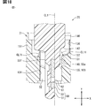
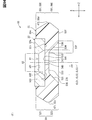
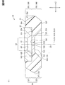
- FIGS. 15 and 16 the internal structure of the sensor SA50 is simplified and only the mold portion 55 and the flow rate sensor 22 are shown.
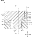
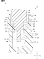
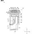
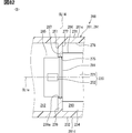
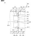
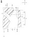
- the housing 21 has a front throttle portion 111 and a back throttle portion 112. These throttle portions 111 and 112 gradually throttle the measurement flow path 32 so that the cross-sectional area S4 of the measurement flow path 32 gradually decreases from the upstream of the measurement inlet 35 or the like toward the flow rate sensor 22. Further, the narrowing portions 111 and 112 gradually narrow the measurement flow path 32 so that the cross-sectional area S4 gradually decreases from the flow rate sensor 22 downstream of the measurement outlet 36 and the like toward the flow rate sensor 22.
- the area of the region orthogonal to the center line CL4 is referred to as the cross-sectional area S4, and this cross-sectional area S4 can also be referred to as the flow path area.
- the front diaphragm portion 111 is a convex portion in which a part of the front measurement wall surface 103 protrudes toward the back measurement wall surface 104.
- the back diaphragm portion 112 is a convex portion in which a part of the back measurement wall surface 104 projects toward the front measurement wall surface 103.
- the front diaphragm portion 111 and the back diaphragm portion 112 are arranged in the height direction Y and face each other in the height direction Y. These throttle portions 111 and 112 are spread over the measurement ceiling surface 102 and the measurement floor surface 101.
- the throttle portions 111 and 112 gradually reduce the measurement width dimension W1 which is the separation distance between the front measurement wall surface 103 and the back measurement wall surface 104 in the width direction X from the upstream toward the flow rate sensor 22. Further, the throttle portions 111 and 112 gradually reduce the measurement width dimension W1 from the downstream toward the flow rate sensor 22.
- the throttle portions 111 and 112 are gradually approaching the center line CL4 from the upstream side toward the flow rate sensor 22 in the measurement flow path 32.
- the separation distances W2 and W3 between the throttle portions 111 and 112 and the center line CL4 in the width direction X gradually decrease from the upstream toward the flow rate sensor 22.
- the throttle portions 111 and 112 gradually approach the center line CL4 from the downstream side toward the flow rate sensor 22 in the measurement flow path 32.
- the separation distances W2 and W3 between the throttle portions 111 and 112 and the center line CL4 in the width direction X gradually decrease from the downstream toward the flow rate sensor 22.
- the portions closest to the center line CL4 are the top portions 111a and 112a.
- the distances W2 and W3 from the center line CL4 are the smallest at the top portions 111a and 112a.
- the front top portion 111a is the top of the front throttle portion 111
- the back top portion 112a is the top of the back throttle portion 112.
- the front top portion 111a and the back top portion 112a are arranged in the width direction X and face each other.
- the flow rate sensor 22 is provided between the front throttle portion 111 and the back throttle portion 112. Specifically, the central CO1 of the heat generating resistor 71 of the flow rate sensor 22 is provided between the front top portion 111a and the back top portion 112a. Regarding the heat generation resistor 71, when a linear virtual line that passes through the center CO1 and is orthogonal to the center line CL1 and extends in the width direction X is called the center line CL5, both the front top portion 111a and the back top portion 112a are the center line CL5. It is placed on top.
- the center CO1 of the heat generating resistor 71 and the front top portion 111a are arranged in the width direction X, and the center CO1 of the heat generating resistor 71 and the front top portion 111a face each other in the width direction X.
- the sensor support portion 51 of the sensor SA50 is provided at a position closer to the front diaphragm portion 111 than the back diaphragm portion 112 in the width direction X. That is, the sensor support portion 51 is provided at a position closer to the front measurement wall surface 103 than the back measurement wall surface 104.
- the front distance L1 which is the distance between the flow sensor 22 in the width direction X and the front measurement wall surface 103, is the distance between the flow sensor 22 and the back measurement wall surface 104 in the width direction X. It is smaller than the back distance L2, which is the separation distance of. That is, the relationship of L1 ⁇ L2 is established.
- the table distance L1 is the distance between the center CO1 of the heat generating resistor 71 and the front top portion 111a of the front throttle portion 111.
- the back distance L2 is the separation distance between the back surface 55f of the mold and the back top portion 112a of the back drawing portion 112 on the center line CL5 of the heat generating resistor 71.
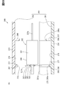
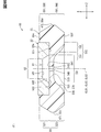
- the mold tip surface 55a of the sensor support portion 51 is arranged at a position closer to the measurement floor surface 101 than the measurement ceiling surface 102 in the height direction Y.
- the floor distance L3 is smaller than the surface distance L1. That is, the relationship of L1> L3 is established.
- the floor distance L3 is the distance between the mold tip surface 55a and the measurement floor surface 101 in the height direction Y. Specifically, it is the distance between the portion of the measurement floor surface 101 facing the mold tip surface 55a and the portion closest to the mold tip surface 55a and the mold tip surface 55a.
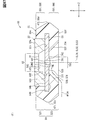
- a planar region orthogonal to the center line CL4 and passing through the center CO1 of the heat generating resistor 71 is referred to as a sensor region 121. ..
- the air flowing from the measurement inlet 35 to the measurement outlet 36 in the measurement flow path 32 needs to pass through the sensor region 121.
- the sensor area 121 has a front area 122 and a back area 123.
- the table area 122 is an area on the surface measurement wall surface 103 side of the mold surface 55e in the width direction X.
- the back area 123 is an area on the back measurement wall surface 104 side of the mold back surface 55f in the width direction X. These areas 122 and 123 extend from the measurement floor surface 101 toward the measurement ceiling surface 102 in the height direction Y.
- the sensor SA50 is arranged between the front area 122 and the back area 123 in the width direction X.
- the table area 122 has a floor side area 122a and a ceiling side area 122b.
- the floor side region 122a is a region extending from the floor side end portion of the flow rate sensor 22 toward the measurement floor surface 101 in the table region 122.
- the end portion on the front end side of the housing is formed by the measurement floor surface 101. Therefore, the floor side region 122a is an region between the flow rate sensor 22 and the measurement floor surface 101 in the height direction Y.
- the ceiling side region 122b is a region extending from the ceiling side end portion of the flow rate sensor 22 toward the measurement ceiling surface 102 in the table region 122.
- the end portion on the base end side of the housing is formed by the ceiling side boundary portion which is the boundary portion between the inner surface of the housing 21 and the outer surface of the sensor SA50. Therefore, the ceiling side region 122b is an region between the flow rate sensor 22 and the ceiling side boundary portion in the height direction Y.
- this area area S1 is the cross-sectional area of the portion of the measurement flow path 32 where the flow rate sensor 22 is provided.
- the area area S1 includes a floor side area S2 which is the area of the floor side area 122a and a ceiling side area S3 which is the area of the ceiling side area 122b.
- the ceiling side area S3 is smaller than the floor side area S2. That is, the relationship S3 ⁇ S2 is established.
- the surface distance L1 is larger than the floor distance L3 in the measurement flow path 32.
- the amount of air flowing along the front measurement wall surface 103 and the mold surface 55e tends to be larger than the amount of air flowing along the measurement floor surface 101 and the mold tip surface 55a.
- the accuracy of detecting the flow rate by the flow rate sensor 22 can be improved, and as a result, the accuracy of measuring the air flow rate by the air flow meter 20 can be improved.
- the measurement flow path 32 will be narrowed down from the measurement floor surface 101 side and the area area S1 of the sensor area 121 will be insufficient.
- the cross-sectional area such as the region area S1
- the pressure loss increases, and it becomes difficult for air to flow from the passing flow path 31 into the measurement flow path 32.
- the air flow rate in the measurement flow path 32 is insufficient, and the flow rate is likely to be separated or turbulent in the measurement flow path 32, and noise is likely to be included in the detection result of the flow rate sensor 22 due to the separation or turbulence. It ends up.
- the front distance L1 is smaller than the back distance L2 in the measurement flow path 32.
- the back region 123 between the mold back surface 55f and the back measurement wall surface 104 is relatively wide.
- the shortage of the area S1 of the sensor region 121 is suppressed by the back region 123, and the shortage of the air flow rate in the measurement flow path 32 is less likely to occur.
- the flow rate is less likely to be separated or turbulent in the measurement flow path 32, and it is possible to suppress the inclusion of noise in the detection result of the flow rate sensor 22.
- the range of the flow rate detection by the flow rate sensor 22 can be expanded. That is, fluctuations in the output of the air flow meter 20 are suppressed, and the air flow meter 20 can be made into a dynamic range. Therefore, for the air flow meter 20, both output fluctuation suppression and dynamic range can be realized.
- the front distance L1 is smaller than the back distance L2.
- the front distance L1 is smaller than the back distance L2.
- the housing 21 has a front diaphragm portion 111.
- the front throttle unit 111 since the front throttle unit 111 gradually narrows the measurement flow path 32 from the measurement inlet 35 side toward the flow rate sensor 22, even if the air flow is separated or disturbed, the front throttle portion 111 By rectifying the air flow, these separations and turbulences are reduced. In this case, peeling or turbulence is less likely to reach the flow sensor 22, so that the detection accuracy of the flow sensor 22 can be improved.
- the table distance L1 is the distance between the front throttle portion 111 and the flow rate sensor 22, the air flowing along the flow rate sensor 22 can be reliably rectified by the front throttle portion 111.
- the table distance L1 is the distance between the front top portion 111a of the front throttle portion 111 and the flow rate sensor 22.
- the portion having the highest rectifying effect tends to be the front top portion 111a. Therefore, by facing the portion having the highest rectifying effect to the flow sensor 22, the air flowing along the flow sensor 22 is separated or disturbed. Can be reliably suppressed from being included. As a result, the detection accuracy of the flow rate sensor 22 can be further improved.
- the housing 21 has a back throttle portion 112.
- the back throttle portion 112 since the back throttle portion 112 gradually narrows the measurement flow path 32 from the measurement inlet 35 side toward the flow rate sensor 22, even if the air flow is separated or disturbed, the back throttle portion 112 causes the air to flow. By rectifying the flow of air, these peeling and turbulence are reduced.
- the air flowing toward the flow rate sensor 22 at a height position near the flow rate sensor 22 in the height direction Y easily passes through both the front side and the back side of the sensor support portion 51. Therefore, it is effective to rectify the air flowing along the back measurement wall surface 104 by the back throttle portion 112 in order to prevent peeling and turbulence from reaching the flow rate sensor 22.
- the ceiling side area S3 of the ceiling side area 122b is smaller than the floor side area S2 of the floor side area 122a.
- the ceiling side region 122b is more likely to have a pressure loss than the floor side region 122a, and air is less likely to flow. Therefore, even if the measurement flow path 32 has a configuration in which the air flowing along the measurement ceiling surface 102 tends to be faster or more than the air flowing along the measurement floor surface 101, the ceiling side region 122b And the floor side region 122a can make the speed and amount of air flowing uniform. As a result, it is possible to prevent the detection accuracy of the flow rate sensor 22 from being lowered due to the mixture of the fast airflow and the slow airflow in the airflow reaching the sensor region 121.
- the measurement flow path 32 is bent so that the measurement ceiling surface 102 is on the outer peripheral side and the measurement floor surface 101 is on the inner peripheral side.
- the air flowing along the measurement ceiling surface 102 tends to be faster or more than the air flowing along the measurement floor surface 101. Therefore, it is effective that the ceiling side area S3 is smaller than the floor side area S2 in order to make the speed and the amount of air flowing in the ceiling side area 122b and the floor side area 122a uniform.
- the surface distance L1 is the distance between the table measurement wall surface 103 and the heat generating resistor 71.
- the flow rate is detected for the air flowing along the heat generation resistor 71. Therefore, by managing the positional relationship between the heat generation resistor 71 and the surface measurement wall surface 103, the detection accuracy of the flow rate sensor 22 Can be enhanced.
- both the mold front surface 55e and the mold back surface 55f are formed by the resin mold portion 55.
- peeling and turbulence are less likely to occur in the air flowing along the mold front surface 55e and the mold back surface 55f.
- the housing 21 has an SA accommodating area 150.
- the SA accommodating area 150 is provided on the base end side of the housing with respect to the bypass flow path 30, and accommodates a part of the sensor SA50. At least the mold base end surface 55b of the sensor SA50 is housed in the SA housing area 150.
- the measurement flow path 32 and the SA accommodating area 150 are arranged in the height direction Y.
- the sensor SA50 is arranged at a position straddling the boundary portion between the measurement flow path 32 and the SA accommodation area 150 in the height direction Y. At least the mold tip surface 55a of the sensor SA50 and the flow rate sensor 22 are housed in the measurement flow path 32.
- the SA accommodation area 150 corresponds to the accommodation area. Further, in FIGS. 17 and 18, the illustration of the internal structure of the sensor SA50 is simplified, and the illustration is limited to the mold portion 55 and the flow rate sensor 22.
- the housing 21 has a first housing portion 151 and a second housing portion 152. These housing portions 151 and 152 are assembled and integrated with each other, and the housing 21 is formed in this state.
- the first housing portion 151 forms the SA accommodating area 150.
- the first housing portion 151 forms a bypass flow path 30 in addition to the SA accommodating area 150.
- the inner surface of the first housing portion 151 forms the SA accommodating region 150 and the bypass flow path 30 as the inner surface of the housing 21.
- a housing opening 151a (see FIG. 19) is provided at the open end of the first housing portion 151.
- the housing opening 151a opens the SA accommodating area 150 toward the side opposite to the measurement flow path 32.
- a gap is formed between the outer surface of the sensor SA50 and the inner surface of the first housing portion 151.
- the second housing portion 152 fills this gap. Specifically, the second housing portion 152 is in a state of being inserted between the outer surface of the sensor SA50 and the inner surface of the first housing portion 151 in the SA accommodating area 150.
- the housing 21 has a housing partition 131.
- the housing partition portion 131 is a convex portion provided on the inner surface of the first housing portion 151, and protrudes from the first housing portion 151 toward the sensor SA50.
- the first housing portion 151 has the housing partition portion 131.
- the tip of the housing partition 131 is in contact with the outer surface of the sensor SA50.
- the housing partition 131 partitions the SA accommodating region 150 and the measurement flow path 32 between the outer surface of the sensor SA50 and the inner surface of the first housing portion 151.
- the inner surface of the first housing portion 151 has a housing flow path surface 135, a housing accommodating surface 136, and a housing step surface 137.
- the housing flow path surface 135, the housing accommodating surface 136, and the housing step surface 137 extend in a direction intersecting the height direction Y, and circulate around the sensor SA50 in an annular shape.
- the center line CL1 of the heat generating resistor 71 extends in the height direction Y
- the housing flow path surface 135, the housing accommodating surface 136, and the housing step surface 137 each extend around the center line CL1 in the circumferential direction. It is extending.
- a housing step surface 137 is provided between the housing tip surface 21a and the housing base end surface 21b.
- the housing step surface 137 faces the housing base end side in the height direction Y.
- the step surface 137 of the housing is inclined with respect to the center line CL1 and faces inward in the radial direction on the center line CL1 side.
- the housing step surface 137 intersects in the height direction Y and corresponds to the housing intersection surface.
- On the inner surface of the first housing portion 151 each of the protruding corner portion between the housing flow path surface 135 and the housing stepped surface 137 and the inside corner portion between the housing accommodating surface 136 and the housing stepped surface 137 are chamfered.
- the height direction Y corresponds to the arrangement direction in which the measurement flow path and the accommodation area are lined up.
- the housing flow path surface 135 forms a measurement flow path 32, and extends from the inner peripheral end portion of the housing step surface 137 toward the housing tip side.
- the housing flow path surface 135 extends from the housing step surface 137 toward the side opposite to the SA accommodating area 150.
- the housing accommodating surface 136 forms the SA accommodating region 150, and extends from the outer peripheral end of the housing step surface 137 toward the housing base end side.
- the housing accommodating surface 136 extends from the housing step surface 137 toward the side opposite to the measurement flow path 32.
- the housing step surface 137 is provided between the housing flow path surface 135 and the housing accommodating surface 136, and forms a step on the inner surface of the first housing portion 151.
- the housing step surface 137 connects the housing flow path surface 135 and the housing accommodating surface 136.
- the outer surface of the sensor SA50 is formed by the outer surface of the mold portion 55.
- the outer surface of the sensor SA50 has an SA flow path surface 145, an SA accommodating surface 146, and an SA step surface 147.
- the SA flow path surface 145, the SA accommodating surface 146, and the SA step surface 147 extend in a direction intersecting the height direction Y, and are portions that circle around the outer surface of the sensor SA50.
- the SA flow path surface 145, the SA accommodating surface 146, and the SA step surface 147 extend in the circumferential direction around the center line CL1 of the heat generating resistor 71.
- an SA step surface 147 is provided between the mold tip surface 55a and the mold base end surface 55b.
- the SA step surface 147 faces the mold tip surface 55a side in the height direction Y.
- the SA stepped surface 147 is inclined with respect to the center line CL1 and faces the radial outer side opposite to the center line CL1.
- the SA step surface 147 intersects in the height direction Y and corresponds to the unit intersection surface.
- the SA flow path surface 145 corresponds to the unit flow path surface
- the SA accommodating surface 146 corresponds to the unit accommodating surface.
- each of the inside corner portion between the SA flow path surface 145 and the SA step surface 147 and the outside corner portion between the SA accommodating surface 146 and the SA step surface 147 is chamfered.
- the SA flow path surface 145 forms a measurement flow path 32, and extends in the height direction Y from the inner peripheral end portion of the SA step surface 147 toward the mold tip side.
- the SA flow path surface 145 extends from the SA step surface 147 toward the side opposite to the SA accommodating area 150.
- the SA accommodating surface 146 forms the SA accommodating region 150, and extends from the outer peripheral end portion of the SA stepped surface 147 toward the mold base end side.
- the SA accommodating surface 146 extends from the SA step surface 147 toward the side opposite to the measurement flow path 32.
- the SA step surface 147 is provided between the SA flow path surface 145 and the SA accommodating surface 146, and forms a step on the outer surface of the sensor SA50.
- the SA step surface 147 connects the SA flow path surface 145 and the SA accommodating surface 146.
- each of the SA flow path surface 145, the SA accommodating surface 146, and the SA step surface 147 is formed by the mold upstream surface 55c, the mold downstream surface 55d, the mold surface 55e, and the mold back surface 55f.
- the housing step surface 137 facing the housing base end side and the SA step surface 147 facing the housing tip side face each other.
- the housing flow path surface 135 facing the inner peripheral side and the SA flow path surface 145 facing the outer peripheral side face each other.
- the housing accommodating surface 136 facing the inner peripheral side and the SA accommodating surface 146 facing the outer peripheral side face each other.
- the housing partition 131 is provided on the stepped surface 137 of the housing and extends in the height direction Y toward the base end side of the housing.
- the center line CL11 of the housing partition 131 extends linearly in the height direction Y.
- the housing partition 131 circles around the sensor SA50 together with the housing step surface 137 in an annular shape.
- the housing partition 131 has a portion extending in the width direction X and a portion extending in the depth direction Z, and has a substantially rectangular frame shape as a whole.
- the tip of the housing partition 131 is in contact with the SA step surface 147 of the sensor SA50.
- the housing partition portion 131 and the SA stepped surface 147 are in close contact with each other to improve the sealing property of the portion partitioning the SA accommodating area 150 and the measurement flow path 32.
- the SA stepped surface 147 is a flat surface extending straight in the direction intersecting the height direction Y.
- the housing step surface 137 and the SA step surface 147 do not extend in parallel, and the SA step surface 147 is inclined with respect to the housing step surface 137.
- the housing partition portion 131 is in contact with the SA step surface 147, so that the outer surface of the sensor SA50 and the first housing portion 151 The sealing property at the part in contact with the inner surface is enhanced.
- the housing step surface 137 and the SA step surface 147 may extend in parallel.
- the housing partition 131 is orthogonal to the housing step surface 137.
- the center line CL11 of the housing partition 131 and the housing step surface 137 are orthogonal to each other.
- the housing partition 131 has a tapered shape.
- the directions X and Z orthogonal to the height direction Y are the width directions for the housing partition 131, and the width dimension of the housing partition 131 in the width direction gradually decreases toward the tip of the housing partition 131. ing.
- Each of the pair of side surfaces of the housing partition 131 extends straight from the housing stepped surface 137.
- the housing partition 131 has a tapered cross section.
- the housing partition 131 is arranged on the housing step surface 137 at a position closer to the housing flow path surface 135 than the housing accommodating surface 136. In this case, in the directions X and Z orthogonal to the height direction Y, the separation distance between the housing partition 131 and the housing accommodating surface 136 is smaller than the separation distance between the housing partition 131 and the housing flow path surface 135. ..
- the portion on the housing flow path surface 135 side of the housing partition portion 131 forms the measurement flow path 32 together with the housing flow path surface 135.
- the portion of the housing partition portion 131 on the side of the housing accommodating surface 136 forms the SA accommodating area 150 together with the housing accommodating surface 136.
- the portion on the SA flow path surface 145 side of the housing partition 131 forms the measurement flow path 32 together with the SA flow path surface 145.
- the portion on the SA accommodating surface 146 side of the housing partition 131 forms the SA accommodating area 150 together with the SA accommodating surface 146.
- the manufacturing process of the air flow meter 20 includes a step of manufacturing the sensor SA50 and a step of manufacturing the first housing portion 151 by resin molding or the like. After these steps, a step of assembling the sensor SA50 to the first housing portion 151 is performed.
- the mold portion 55 of the sensor SA50 is resin-molded using the SA type device 580 (see FIGS. 33 and 34) described later.
- an epoxy-based thermosetting resin such as an epoxy resin is used as the resin material for forming the mold portion 55.
- the first housing portion 151 is resin-molded using a housing type device or the like.
- a thermoplastic resin such as polybutylene terephthalate (PBT) or polyphenylene sulfide (PPS) is used as the resin material for forming the first housing portion 151.
- PBT polybutylene terephthalate
- PPS polyphenylene sulfide
- the first housing portion 151 formed of the thermoplastic resin in this way is softer than the mold portion 55 formed of the thermosetting resin. In other words, the first housing portion 151 has a lower hardness and a higher flexibility than the mold portion 55.
- the shape and size of the measurement outlet 36 are set so that the length dimension of the outer peripheral edge of the measurement outlet 36 is as small as possible. This makes it possible to reduce the possibility of burrs occurring on the outer peripheral edge of the measurement outlet 36 and reduce the amount of burrs generated on the outer peripheral edge of the measurement outlet 36. Therefore, with respect to the measurement outlet 36, it is possible to reduce the work load when removing burrs and to prevent the air flow flowing out from the measurement outlet 36 from being disturbed by burrs.
- the flow velocity of the air flowing out from the measurement outlet 36 tends to increase. In this case, it is difficult for air to flow out from the measurement outlet 36 due to the force of the air flowing through the intake passage 12, so that the flow velocity in the measurement flow path 32 is unlikely to decrease, and as a result, the flow rate sensor 22 The detection accuracy is likely to improve.
- the sensor SA50 is inserted into the inside of the first housing portion 151 from the housing opening 151a (see FIG. 19) as shown in FIG.
- the sensor SA50 is further pushed into the inside of the first housing portion 151 toward the housing tip end side.
- the tip of the housing partition 131 is crushed by the SA stepped surface 147 because the hardness of the first housing portion 151 is lower than the hardness of the mold portion 55. It transforms like this.
- the newly formed tip surface is easily brought into close contact with the SA step surface 147 by crushing the tip, and the sealing property between the housing partition 131 and the SA step surface 147 is enhanced.
- a portion of the housing partition 131 that has been crushed by the sensor SA50 is shown as an alternate long and short dash line as a virtual line.
- the crushed residue is hard to enter the measurement flow path 32.
- the accommodation side angle ⁇ 12 facing the SA accommodation area 150 is the measurement flow path 32. It is larger than the flow path side angle ⁇ 11 facing. That is, the relationship of ⁇ 12> ⁇ 11 is established.
- the tip of the housing partition 131 is more likely to fall or collapse toward the SA accommodating area 150 side than the measurement flow path 32 side. Therefore, even if crushed residue is generated, it is difficult for the crushed residue to enter the measurement flow path 32.
- the flow path side angle ⁇ 11 is the angle of the portion of the outer surface of the housing partition 131 that is closest to the SA step surface 147, and the accommodation side angle ⁇ 12 is the angle opposite to the flow path side angle ⁇ 11 with the center line CL11 in between. is there.
- a step of resin molding the second housing portion 152 using a housing type device or the like is performed.
- the housing type device is mounted on the first housing portion 151 together with the sensor SA50, and the molten resin obtained by melting the resin material is injected from the injection molding machine and press-fitted into the housing type device.
- the molten resin is filled in the gap between the first housing portion 151 and the sensor SA50.
- the housing partition 131 is in close contact with the outer surface of the sensor SA50 as described above, it is restricted that the molten resin enters the measurement flow path 32 through the gap between the first housing portion 151 and the sensor SA50. .. Then, the second housing portion 152 is formed by solidifying the molten resin inside the housing type device.
- thermoplastic resin such as polybutylene terephthalate (PBT) or polyphenylene sulfide (PPS) is used as in the case of the first housing portion 151.
- PBT polybutylene terephthalate
- PPS polyphenylene sulfide
- Both the first housing portion 151 and the second housing portion 152 contain a conductive carbon material.
- the carbon material include carbon powder, carbon fiber, nanocarbon, graphene, and carbon microparticles.
- the first housing portion 151 is more likely to be discharged when charged than the second housing portion 152.
- the content of the carbon material in the first housing portion 151 is larger than that in the second housing portion 152.
- the first housing portion 151 includes more of the conductive portion than the second housing portion 152.
- the conductive portion contains a plurality of carbon powders, carbon fibers, nanocarbons, graphene and carbon microparticles, and examples of nanocarbons include carbon nanotubes, carbon nanofibers and fullerenes.
- the housing partition 131 protruding from the inner surface of the housing 21 partitions the measurement flow path 32 and the SA accommodating area 150 between the sensor SA50 and the housing 21.
- the tip of the housing partition 131 and the sensor SA50 are easily brought into close contact with each other, so that a gap is less likely to occur between the inner surface of the housing 21 and the outer surface of the sensor SA50. Therefore, when the molten resin is injected into the SA accommodating region 150 of the first housing portion 151 to form the second housing portion 152, the molten resin passes through the gap between the first housing portion 151 and the sensor SA50 to measure the measurement flow path 32. It is regulated to get in.
- the molten resin that has entered the measurement flow path 32 through the gap between the first housing portion 151 and the sensor SA50 solidifies, and the shape of the measurement flow path 32 unintentionally changes depending on the solidified portion. It's getting harder. Further, it is less likely that the solidified portion peels off from the first housing portion 151 and the sensor SA50 in the measurement flow path 32 and comes into contact with or adheres to the flow rate sensor 22 as a foreign substance. Therefore, it is possible to prevent the detection accuracy of the flow rate sensor 22 from being lowered by the molten resin that has entered the measurement flow path 32 from the SA accommodation area 150. As a result, the accuracy of detecting the air flow rate by the flow rate sensor 22 can be improved, and as a result, the accuracy of measuring the air flow rate by the air flow meter 20 can be improved.
- the housing partition 131 circles around the sensor SA50 in an annular shape.
- the housing partition 131 can create a state in which the outer surface of the sensor SA50 and the inner surface of the first housing portion 151 are in close contact with each other on the entire outer surface of the sensor SA50. Therefore, the sealing property of the entire boundary between the measurement flow path 32 and the SA accommodating area 150 can be improved by the housing partition 131.
- the housing partition 131 is provided at a position closer to the housing flow path surface 135 than the housing accommodating surface 136 on the housing step surface 137.
- the measurement flow path 32 and the SA accommodating area 150 are partitioned by the housing partition portion 131 at a position as close as possible to the measurement flow path 32 side, so that the measurement flow in the gap between the first housing portion 151 and the sensor SA50.
- the portion included in the road 32 can be made as small as possible.
- the gap between the first housing portion 151 and the sensor SA50 is a region in which the air flow is likely to be disturbed due to the inflow of air flowing from the measurement inlet 35 toward the measurement outlet 36. It has become.
- the detection accuracy of the flow rate sensor 22 can be improved by providing the housing partition portion 131 at a position as close as possible to the housing flow path surface 135.
- the accommodation side angle ⁇ 12 is larger than the flow path side angle ⁇ 11.
- the housing partition portion 131 is crushed and deformed so as to be folded or collapsed toward the SA accommodating area 150. It's getting easier. Therefore, when the housing partition 131 is deformed and brought into close contact with the outer surface of the sensor SA50, it is less likely that the crushed residue of the housing partition 131 unintentionally enters the measurement flow path 32. Therefore, it is possible to prevent the crushed debris from coming into contact with or adhering to the flow rate sensor 22 in the measurement flow path 32 and reducing the detection accuracy of the flow rate sensor 22.
- the housing partition 131 provided on the housing step surface 137 is in contact with the SA step surface 147.
- the housing step surface 137 and the SA step surface 147 both intersect in the height direction Y and face each other. Therefore, when the sensor SA50 is inserted into the first housing portion 151, the SA step surface is inserted. The surface 147 is caught in the housing partition 131. Therefore, the housing partition portion 131 can be brought into close contact with the SA step surface 147 by simply pushing the sensor SA 50 toward the measurement flow path 32 into the inside of the first housing portion 151. As a result, it is possible to suppress an increase in the work load when assembling the sensor SA50 to the first housing portion 151 while reliably partitioning the measurement flow path 32 and the SA accommodating area 150 by the housing partition portion 131.
- the housing step surface 137 of the first housing portion 151 faces the housing opening 151a side.
- the SA step surface 147 of the sensor SA50 can be pressed against the housing step surface 137 by simply pushing the sensor SA50 inserted into the SA accommodating area 150 from the housing opening 151a toward the measurement flow path 32. .. Therefore, it is possible to realize a configuration in which the housing partition portion 131 of the SA step surface 147 is easily brought into close contact with the housing step surface 137.
- the measurement flow path 32 is curved so that the portion between the measurement inlet 35 and the measurement outlet 36 bulges toward the flow rate sensor 22, and has a U shape as a whole.
- the measurement inlet 35 and the measurement outlet 36 are arranged in the depth direction Z.
- the depth direction Z corresponds to the alignment direction
- the height direction Y is orthogonal to the depth direction Z.
- the portion between the measurement inlet 35 and the measurement outlet 36 is bent so as to bulge in the height direction Y toward the housing base end side.
- the inner surface of the housing 21 has an outer measurement curved surface 401 and an inner measurement curved surface 402.
- the outer measurement curved surface 401 and the inner measurement curved surface 402 extend along the center line CL4 of the measurement flow path 32.
- the inner surface of the housing 21 has a front measurement wall surface 103 and a back measurement wall surface 104 as described above, in addition to the outer measurement curved surface 401 and the inner measurement curved surface 402.
- the outer measurement curved surface 401 and the inner measurement curved surface 402 are arranged in directions Y and Z orthogonal to the width direction X, and face each other via the front measurement wall surface 103 and the back measurement wall surface 104.
- the external measurement curved surface 401 forms the measurement flow path 32 from the outside of the bend, and is provided on the outer peripheral side of the measurement flow path 32 and the flow rate sensor 22.
- the external measurement curved surface 401 is passed to the measurement inlet 35 and the measurement outlet 36.
- the outer measurement curved surface 401 is concavely curved so that the portion between the measurement inlet 35 and the measurement outlet 36 is recessed toward the flow rate sensor 22 as a whole.
- the external measurement curved surface 401 includes a measurement ceiling surface 102, and is provided with an SA insertion hole 107.
- the inner measurement curved surface 402 forms the measuring flow path 32 from the inside of the bend, and is provided on the inner peripheral side of the measuring flow path 32.
- the inner measurement curved surface 402 is passed over the measurement inlet 35 and the measurement outlet 36.
- the inner measurement curved surface 402 is bent so that the portion between the measurement inlet 35 and the measurement outlet 36 bulges toward the flow rate sensor 22 as a whole.
- the inner measurement curved surface 402 does not have a recessed portion toward the side opposite to the outer measurement curved surface 401, and the entire surface is bent convexly so as to bulge toward the outer measurement curved surface 401.
- the inner measurement curved surface 402 includes a measurement floor surface 101.
- the measurement flow path 32 has a sensor path 405, an upstream curved path 406, and a downstream curved path 407.
- the sensor path 405 is a portion of the measurement flow path 32 where the flow rate sensor 22 is provided.
- the sensor path 405 extends straight in the depth direction Z, and extends in the mainstream direction in parallel with the angle setting surface 27a of the flange portion 27.
- the upstream turn 406 and the downstream turn 407 are arranged in the depth direction Z, and the sensor path 405 is provided between the upstream turn 406 and the downstream turn 407, and connects these turns 406 and 407. ing.
- the surface of the housing 21 forming the sensor path 405 includes at least a part of the measurement floor surface 101.
- the length dimension of the sensor path 405 in the depth direction Z is defined by the measurement floor surface 101.
- the upstream end of the sensor path 405 includes the upstream end of the measurement floor surface 101
- the downstream end of the sensor path 405 includes the downstream end of the measurement floor surface 101.
- the length dimension of the sensor path 405 in the depth direction Z is the same as the length dimension of the measurement floor surface 101.
- the measurement floor surface 101 extends straight in the depth direction Z, and the straight extension of the measurement floor surface 101 is referred to as the sensor path 405 extending straight.
- the upstream curved path 406 extends from the sensor path 405 toward the measurement inlet 35 in the measurement flow path 32, and is provided between the sensor path 405 and the measurement inlet 35.
- the upstream curved path 406 is curved so as to extend from the sensor path 405 toward the measurement inlet 35 in the housing 21.
- the downstream end portion thereof is opened in the depth direction Z toward the sensor path 405, while the upstream end portion thereof is opened in the height direction Y toward the measurement inlet 35.
- the opening direction of the upstream end and the opening direction of the downstream end intersect, and the crossing angle is, for example, 90 degrees.
- the inner surface of the upstream curved road 406 includes a part of the front measurement wall surface 103 and a part of the back measurement wall surface 104.
- the downstream curved path 407 extends from the sensor path 405 toward the measurement outlet 36 in the measurement flow path 32, and is provided between the sensor path 405 and the measurement outlet 36.
- the downstream curved path 407 is curved so as to extend from the sensor path 405 toward the measurement outlet 36 in the housing 21.
- the upstream end portion thereof is opened in the depth direction Z toward the sensor path 405, while the downstream end portion thereof is opened in the height direction Y toward the measurement outlet 36.
- the opening direction of the upstream end portion and the opening direction of the downstream end portion intersect, and the intersection angle is, for example, 90 degrees, as in the upstream curved road 406. .
- the inner surface of the downstream curved road 407 includes a part of the front measurement wall surface 103 and a part of the back measurement wall surface 104.
- the sensor path 405 is included in the detection measurement path 353.
- the upstream curved road 406 is provided at a position straddling the boundary portion between the guide measurement path 352 and the detection measurement path 353 in the height direction Y.
- the upstream curved path 406 has a part of the guide measurement path 352 and a part of the detection measurement path 353.
- the downstream curved road 407 is provided at a position straddling the boundary portion between the detection measurement path 353 and the emission measurement path 354 in the height direction Y. In this case, it has a part of the detection measurement path 353 and a part of the emission measurement path 354.
- the inner surface of the housing 21 has an upstream outer curved surface 411 and an upstream inner curved surface 415 as surfaces forming the upstream curved path 406.
- the upstream outer curved surface 411 forms the upstream curved road 406 from the outside of the curved road, and is provided on the outer peripheral side of the upstream curved road 406.
- the upstream outer curved surface 411 extends so as to be recessed along the center line CL4 of the measurement flow path 32, and is curved so as to be continuously bent along the center line CL4.
- the upstream outer curved surface 411 extends over the upstream end portion and the downstream end portion of the upstream curved road 406, and corresponds to the upstream outer curved surface.
- the upstream inner curved surface 415 forms the upstream curved road 406 from the inside of the curved road, and is provided on the inner peripheral side of the upstream curved road 406.
- the upstream inward curved surface 415 extends so as to bulge along the center line CL4 of the measurement flow path 32, and is curved so as to continuously bend along the center line CL4.
- the upstream inward curved surface 415 extends over the upstream end portion and the downstream end portion of the upstream curved surface 406, and corresponds to the upstream inward curved surface.
- the inner surface of the housing 21 includes a part of the front measurement wall surface 103 and a part of the back measurement wall surface 104 in addition to the upstream outer curved surface 411 and the upstream inner curved surface 415 as the surfaces forming the upstream curved path 406. Have.
- the inner surface of the housing 21 has a downstream outer curved surface 421 and a downstream inner curved surface 425 as surfaces forming the downstream curved path 407.
- the downstream outer curved surface 421 forms the downstream curved road 407 from the outside of the curved road, and is provided on the outer peripheral side of the downstream curved road 407.
- the downstream outer curved surface 421 extends along the center line CL4 of the measurement flow path 32, and is bent at a predetermined angle along the center line CL4.
- the bending angle of the downstream outer bending surface 421 is, for example, 90 degrees.
- the downstream outer curved surface 421 has a downstream outer horizontal surface 422, a downstream outer vertical surface 423, and a downstream outer inner corner portion 424.
- the downstream outer lateral surface 422 extends straight from the upstream end of the downstream curved road 407 toward the downstream side in the depth direction Z.
- the downstream outer vertical surface 423 extends straight from the downstream end of the downstream curved road 407 toward the upstream side in the height direction Y.
- the downstream outer horizontal surface 422 and the downstream outer vertical surface 423 are connected to each other, and form a downstream outer inner corner portion 424 as an inner corner portion that enters each other inward.
- the downstream outer corner portion 424 has a shape in which the downstream outer curved surface 421 is bent at a substantially right angle.
- the downstream inner curved surface 425 forms the downstream curved road 407 from the inside of the curved road, and is provided on the inner peripheral side of the downstream curved road 407.
- the downstream inward curved surface 425 extends so as to bulge along the center line CL4 of the measurement flow path 32, and is curved so as to continuously bend along the center line CL4.
- the downstream inward curved surface 425 spans the upstream end portion and the downstream end portion of the downstream curved surface 407, and corresponds to the downstream inward curved surface.
- the inner surface of the housing 21 includes a part of the front measurement wall surface 103 and a part of the back measurement wall surface 104 in addition to the downstream outer curved surface 421 and the downstream inner curved surface 425 as surfaces forming the downstream curved path 407. Have.
- the outer measurement curved surface 401 includes an upstream outer curved surface 411 and a downstream outer curved surface 421.
- Each of the upstream outer curved surface 411 and the downstream outer curved surface 421 includes a part of the measurement ceiling surface 102.
- the inner measurement curved surface 402 includes an upstream inner curved surface 415 and a downstream inner curved surface 425 in addition to the measurement floor surface 101 described above.
- the degree of swelling of the downstream inward curved surface 425 toward the side where the measurement flow path 32 is expanded becomes smaller than the degree of swelling of the upstream inward curved surface 415 toward the side where the measurement flow path 32 is expanded.
- the length dimension of the downstream inner curved surface 425 is larger than the length dimension of the upstream inner curved surface 415.
- the radius of curvature R32 of the downstream inwardly curved surface 425 is larger than the radius of curvature R31 of the upstream inwardly curved surface 415. That is, the relationship of R32> R31 is established.
- the bend of the downstream inward curved surface 425 is looser than the bend of the upstream inward curved surface 415.
- the degree of dent of the downstream outer curved surface 421 toward the side where the measurement flow path 32 is expanded becomes larger than the degree of dent of the upstream outer curved surface 411 toward the side where the measurement flow path 32 is expanded.
- the downstream outer curved surface 421 is bent at a right angle, while the upstream outer curved surface 411 is curved.
- the length dimension of the bent portion on the downstream outer curved surface 421 is a very small value, which is smaller than the length dimension of the upstream outer curved surface 411. It has become.
- the radius of curvature can be calculated for the bent portion of the downstream outer curved surface 421, the radius of curvature is almost zero, which is smaller than the radius of curvature R33 of the upstream outer curved surface 411.
- the bend of the downstream outer curved surface 421 is tighter than the bend of the upstream outer curved surface 411.
- the degree of dent of the upstream outer curved surface 411 toward the side where the measurement flow path 32 is expanded becomes smaller than the degree of bulging of the upstream inner curved surface 415 toward the side where the measurement flow path 32 is expanded.
- the length dimension of the upstream outer curved surface 411 is larger than the length dimension of the upstream inner curved surface 415.
- the radius of curvature R33 of the upstream outer curved surface 411 is larger than the radius of curvature R31 of the upstream inner curved surface 415. That is, the relationship of R33> R31 is established.
- the degree of dent of the downstream outer curved surface 421 toward the side where the measurement flow path 32 is expanded becomes larger than the degree of bulging of the downstream inner curved surface 425 toward the side where the measurement flow path 32 is expanded.
- the length dimension of the downstream outer curved surface 421 is smaller than the length dimension of the downstream inner curved surface 425.
- the degree of denting of the downstream outer curved surface 421 is larger than the degree of swelling of the downstream inner curved surface 425, so that the cross-sectional area of the downstream curved road 407 is increased in the cross-sectional area S4 of the measurement flow path 32. It is as large as possible.
- the separation distance L35b between the downstream outer curved surface 421 and the downstream inner curved surface 425 is the upstream outer curved surface 411 and the upstream.
- the distance from the inner curved surface 415 is larger than the distance L35a. That is, the relationship of L35b> L35a is established.
- the separation distance L35b between the downstream outer curved surface 421 and the downstream inner curved surface 425 is the separation distance at the portion where the downstream outer curved surface 421 and the downstream inner curved surface 425 are most separated from each other on the downstream curved road 407.
- the portion where the downstream outer curved surface 421 and the downstream inner curved surface 425 are most separated from each other is, for example, a portion where the downstream outer inner corner portion 424 of the downstream outer curved surface 421 and the central portion of the downstream inner curved surface 425 face each other.
- the separation distance L35a between the upstream outer curved surface 411 and the upstream inner curved surface 415 is the separation distance at the portion where the upstream outer curved surface 411 and the upstream inner curved surface 415 are most separated from each other on the upstream curved road 406.
- the portion where the upstream outer curved surface 411 and the upstream inner curved surface 415 are most separated from each other is, for example, a portion where the central portion of the upstream outer curved surface 411 and the central portion of the upstream inner curved surface 415 face each other.
- the line CL31 is assumed as a virtual straight line that passes through the flow rate sensor 22 and extends in the depth direction Z.
- the line CL31 passes through the center CO1 of the heat generation resistor 71 of the flow sensor 22, and is orthogonal to both the center lines CL1 and CL5 of the heat generation resistor 71.
- the depth direction Z corresponds to the line direction of the upstream turn 406 and the downstream turn 407.
- the line CL31 and the center line CL4 of the measurement flow path 32 extend in parallel.
- the line CL31 extends parallel to the angle setting surface 27a of the housing 21.
- the line CL31 passes through each of the sensor path 405, the upstream curved path 406, and the downstream curved path 407, and intersects each of the upstream outer curved surface 411 and the downstream outer curved surface 421.
- the line CL31 intersects the downstream outer vertical surface 423.
- the sensor path 405 extends straight along the line CL31.
- the separation distance L31b between the flow rate sensor 22 and the downstream outer curved surface 421 is larger than the separation distance L31a between the flow rate sensor 22 and the upstream outer curved surface 411. That is, the relationship of L31b> L31a is established.
- the flow rate sensor 22 is provided at a position closer to the upstream outer curved surface 411.
- the separation distances L31a and L31b are the distances to the center line CL5 of the heat generating resistor 71.
- the sensor support portion 51 is provided at a position closer to the upstream outer curved surface 411, so that the flow rate sensor 22 is provided at a position closer to the upstream outer curved surface 411.
- the separation distance L32b between the sensor support portion 51 and the downstream outer curved surface 421 is larger than the separation distance L32a between the sensor support portion 51 and the upstream outer curved surface 411. That is, the relationship of L32b> L32a is established.
- the separation distance between the sensor support portion 51 in the depth direction Z and the upstream outer curved surface 411 is set between the sensor support portion 51 and the downstream outer side in the depth direction Z even in a portion not on the line CL31. It is larger than the distance from the curved surface 421.
- the separation distance between the portion of the mold upstream surface 55c of the sensor support portion 51 through which the line CL31 passes and the upstream outer curved surface 411 is defined as the separation distance L32a. Further, the separation distance between the portion of the downstream surface 55d of the mold of the sensor support portion 51 through which the line CL31 passes and the downstream outer curved surface 421 is defined as the separation distance L32b.
- the sensor path 405 is provided at a position closer to the upstream outer curved surface 411 between the upstream outer curved surface 411 and the downstream outer curved surface 421.
- the separation distance L33b between the sensor path 405 and the downstream outer curved surface 421 on the line L31 is larger than the separation distance L33a between the sensor path 405 and the upstream outer curved surface 411. That is, the relationship of L33b> L33a is established.
- the flow rate sensor 22 is provided at a position closer to the upstream curved path 406 on the sensor path 405.
- the separation distance L34b between the flow rate sensor 22 and the downstream curved path 407 on the line L31 is larger than the separation distance L34a between the flow rate sensor 22 and the upstream curved path 406. That is, the relationship of L34b> L34a is established.
- the sum of the separation distance L34a and the separation distance L34b is the length dimension of the sensor path 405 in the depth direction Z.
- the housing 21 has the throttle portions 111 and 112 shown in FIGS. 24 and 25. These throttle portions 111 and 112 are provided on the measurement wall surfaces 103 and 104, and form a part of the measurement wall surfaces 103 and 104. 24 and 25 show a side-by-side cross section CS41.
- the line-up cross section CS41 is a cross section that extends along the line-up line CL41 and extends in the direction in which the measurement wall surfaces 103 and 104 are lined up. Further, the arranged cross section CS41 is orthogonal to the height direction Y.
- the front diaphragm surface 103 has a front diaphragm surface 431, a front diaphragm surface 432, a front diaphragm upstream surface 433, and a front diaphragm downstream surface 434.
- the front diaphragm surface 431 and the front expansion surface 432 are formed by the front diaphragm portion 111, and are included in the outer surface of the front diaphragm portion 111. That is, the front diaphragm portion 111 has a front diaphragm surface 431 and a front diaphragm surface 432.
- the front diaphragm surface 431 extends in the depth direction Z from the front top portion 111a toward the upstream curved road 406, and the front expansion surface 432 extends from the front top portion 111a toward the downstream curved road 407 in the depth direction Z. Extends to.
- the front top portion 111a is a boundary portion between the front diaphragm surface 431 and the front expansion surface 432.
- the front diaphragm surface 431 is inclined with respect to the center line CL4 of the measurement flow path 32 in the detection measurement path 353, and faces the upstream outer curved surface 411 side.
- the front throttle surface 431 is narrowed by gradually reducing the measurement flow path 32 from the measurement inlet 35 toward the flow rate sensor 22.
- the cross-sectional area S4 of the measurement flow path 32 gradually decreases from the upstream end portion of the front diaphragm surface 431 toward the front top portion 111a.
- the front diaphragm surface 431 is curved so that the portion between the upstream end portion and the downstream end portion bulges toward the center line CL4 of the measurement flow path 32.
- the front expansion surface 432 is inclined with respect to the center line CL4 of the measurement flow path 32 in the detection measurement path 353, and faces the downstream outer curved surface 421 side.
- the front expansion surface 432 gradually expands the measurement flow path 32 from the flow rate sensor 22 side toward the measurement outlet 36.
- the cross-sectional area S4 of the measurement flow path 32 gradually increases from the front top portion 111a toward the downstream end portion of the front expansion surface 432.
- the front expansion surface 432 is curved so that the portion between the upstream end portion and the downstream end portion bulges toward the center line CL4 of the measurement flow path 32.
- the front diaphragm upstream surface 433 extends straight from the upstream end of the front diaphragm surface 431 toward the measurement inlet 35 in parallel with the line CL31.
- the front diaphragm upstream surface 433 is provided between the upstream outer curved surface 411 and the front diaphragm surface 431 on the upstream curved road 406, and is passed over the upstream outer curved surface 411 and the front diaphragm surface 431.
- the front expansion downstream surface 434 extends straight from the downstream end of the front expansion surface 432 toward the measurement outlet 36 in parallel with the line CL31.
- the front expansion downstream surface 434 is provided between the downstream outer curved surface 421 and the front expansion surface 432 on the downstream curved road 407, and extends over the downstream outer curved surface 421 and the front expansion surface 432.
- the upstream surface 433 of the front diaphragm and the downstream surface 434 of the front expansion are arranged in the depth direction Z, and are flush with each other because the positions of the width directions X overlap.
- the back measurement wall surface 104 has a back diaphragm surface 441, a back expansion surface 442, a back diaphragm upstream surface 443, and a back expansion downstream surface 444.
- the back drawing surface 441 and the back expanding surface 442 are formed by the back drawing portion 112, and are included in the outer surface of the back drawing portion 112. That is, the back diaphragm portion 112 has a back diaphragm surface 441 and a back expansion surface 442.
- the back diaphragm surface 441 extends in the depth direction Z from the back top portion 112a toward the upstream curved road 406, and the back expansion surface 442 extends from the back top portion 112a toward the downstream curved road 407 in the depth direction Z. Extends to.
- the back top portion 112a is a boundary portion between the back drawing surface 441 and the back expansion surface 442.
- the back diaphragm surface 441 is inclined with respect to the center line CL4 of the measurement flow path 32 in the detection measurement path 353, and faces the upstream outer curved surface 411 side.
- the back throttle surface 441 gradually reduces and narrows the measurement flow path 32 from the measurement inlet 35 toward the flow rate sensor 22.
- the cross-sectional area S4 of the measurement flow path 32 gradually decreases from the upstream end portion of the back diaphragm surface 441 toward the back top portion 112a.
- the back diaphragm surface 441 is curved so that the portion between the upstream end portion and the downstream end portion bulges toward the center line CL4 of the measurement flow path 32.
- the back expansion surface 442 is inclined with respect to the center line CL4 of the measurement flow path 32 in the detection measurement path 353, and faces the downstream outer curved surface 421 side.
- the back expansion surface 442 gradually expands the measurement flow path 32 from the flow rate sensor 22 side toward the measurement outlet 36.
- the cross-sectional area S4 of the measurement flow path 32 gradually increases from the back top portion 112a toward the downstream end portion of the back expansion surface 442.
- the back expansion surface 442 is curved so that the portion between the upstream end portion and the downstream end portion bulges toward the center line CL4 of the measurement flow path 32.
- the back diaphragm upstream surface 443 extends straight from the upstream end of the back diaphragm surface 441 toward the measurement inlet 35 in parallel with the line CL31.
- the back throttle upstream surface 443 is provided between the upstream outer curved surface 411 and the front diaphragm surface 431 on the upstream curved road 406, and is passed over the upstream outer curved surface 411 and the front diaphragm surface 431.
- the back expansion downstream surface 444 extends straight from the downstream end of the back expansion surface 442 toward the measurement outlet 36 in parallel with the line CL31.
- the back expansion downstream surface 444 is provided between the downstream outer curved surface 421 and the back expansion surface 442 in the downstream curved road 407, and extends over the downstream outer curved surface 421 and the back expansion surface 442.
- the upstream surface of the back diaphragm 443 and the downstream surface of the back extension 444 are arranged in the depth direction Z, and are flush with each other because the positions of the width directions X overlap.
- the aperture units 111 and 112 correspond to the measurement aperture units. Further, the front diaphragm surface 431 and the back diaphragm surface 441 correspond to the measurement diaphragm surface, and the front expansion surface 432 and the back expansion surface 442 correspond to the measurement expansion surface. As described above, the center CO1 of the heat generating resistor 71, the front top 111a, and the back top 112a are arranged in the width direction X, and the front top 111a and the back top 112a are on the center line CL5 of the heating resistor 71. Is placed.
- the length dimension W31a of the front diaphragm portion 111 and the length dimension W31b of the back diaphragm portion 112 are the same.
- the length dimension W32a of the front diaphragm surface 431 in the depth direction Z is smaller than the length dimension W33a of the front expansion surface 432 in the depth direction Z.
- the length dimension W32b of the back diaphragm surface 441 in the depth direction Z is smaller than the length dimension W33b of the back expansion surface 442 in the depth direction Z.
- the length dimension W32a of the front diaphragm surface 431 and the length dimension W32b of the back diaphragm surface 441 are the same, and the length dimension W33a of the front expansion surface 432 and the back expansion surface 442 The length dimension W33b is the same.
- the front diaphragm portion 111 is provided at a position closer to the upstream turn road 406 in the depth direction Z.
- the separation distance W34a between the front diaphragm portion 111 and the upstream outer curved surface 411 is larger than the separation distance W35a between the front diaphragm portion 111 and the downstream outer curved surface 421 on the line CL31.
- the back throttle portion 112 is provided at a position closer to the upstream curved road 406 in the depth direction Z, similarly to the front throttle portion 111.
- the separation distance W34b between the back throttle portion 112 and the upstream outer curved surface 411 is larger than the separation distance W35b between the back throttle portion 112 and the downstream outer curved surface 421.
- the separation distance W34a and the separation distance W34b are the same.
- the separation distance W35a and the separation distance W35b are the same.
- the measurement width dimension W1 (see FIG. 15) between the front measurement wall surface 103 and the back measurement wall surface 104 differs depending on the position.
- the measurement width dimension W1 is different between the sensor path 405, the upstream curved path 406, and the downstream curved path 407, and is not uniform in each of the sensor path 405, the upstream curved path 406, and the downstream curved path 407. .
- the separation distance D34 between the front throttle upstream surface 433 and the back throttle upstream surface 443 at the upstream curve 406 is the same as the separation distance D38 between the front expansion downstream surface 434 and the back expansion downstream surface 444 at the downstream curve 407. It has become.
- the sensor support portion 51 is provided at the center position of the front diaphragm upstream surface 433 and the back diaphragm upstream surface 443 on the upstream curved road 406.
- the center line CL32 of the sensor SA50 is assumed.
- the center line CL32 is a linear virtual line that passes through the center of the sensor support portion 51 in the width direction X on the center line CL5 of the heat generating resistor 71, is orthogonal to the center line CL5, and extends in the depth direction Z. Further, the center line CL32 extends in parallel with the line CL31.
- the separation distance D31a between the center line CL32 and the front diaphragm upstream surface 433 is the same as the separation distance D31b between the center line CL32 and the back diaphragm upstream surface 443.
- the sensor support portion 51 is also provided at the center position of the front expansion downstream surface 434 and the back expansion downstream surface 444 in the downstream curved road 407.
- the separation distance D35a between the center line CL32 and the front expansion downstream surface 434 is the same as the separation distance D35b between the center line CL32 and the back expansion downstream surface 444.
- the separation distance D31a and the separation distance D35a are the same.
- the separation distance D31b and the separation distance D35b are the same.
- the protruding dimension of the portion 111 is the same.
- the protrusion dimension D32a of the front top portion 111a with respect to the front diaphragm upstream surface 433 and the protrusion dimension D36a of the front top portion 111a with respect to the front expansion downstream surface 434 are the same.
- the protruding dimension of the front diaphragm surface 431 with respect to the front diaphragm upstream surface 433 gradually increases from the front diaphragm upstream surface 433 toward the front top portion 111a.
- the rate of increase gradually increases from the upstream surface 433 of the front diaphragm toward the top 111a of the front diaphragm, so that the front diaphragm surface 431 becomes a curved surface.
- the protruding dimension of the front expansion surface 432 with respect to the front expansion downstream surface 434 gradually decreases from the front top portion 111a toward the front expansion downstream surface 434. Since this decrease rate gradually increases from the front top portion 111a toward the front expansion downstream surface 434, the front expansion surface 432 becomes a curved surface.
- the length dimension W33a of the front expansion surface 432 is larger than the length dimension W32a of the front diaphragm surface 431.
- the reduction rate of the protrusion dimension of the front expansion surface 432 from the front top portion 111a to the front expansion downstream surface 434 is higher than the increase rate of the protrusion dimension of the front diaphragm surface 431 from the front diaphragm upstream surface 433 to the front diaphragm surface 111a. Is also getting smaller.
- the front diaphragm surface 431 and the front expansion surface 432 are continuous curved surfaces, and the tangent line of the front diaphragm surface 431 and the tangent line of the front diaphragm surface 432 at the front top portion 111a both extend parallel to the line CL31. ..
- the ratio of the length dimension W32a of the front diaphragm surface 431 to the protrusion dimension D32a on the diaphragm side of the front diaphragm portion 111a is called the front diaphragm ratio, and the length dimension W33a of the front expansion surface 432 and the front top portion 111a.
- the ratio with the protrusion dimension D36a on the expansion side is referred to as a table expansion ratio.
- the value obtained by dividing the protrusion dimension D32a on the aperture side by the length dimension W32a is calculated as the table aperture ratio
- the value obtained by dividing the protrusion dimension D36a on the expansion side by the length dimension W33a is calculated as the table expansion ratio.
- the table expansion rate is smaller than the table aperture rate.
- the protruding dimension of the portion 112 is the same.
- the protrusion dimension D32b of the back top portion 112a with respect to the back throttle upstream surface 443 and the protrusion dimension D36b of the back top portion 112a with respect to the back expansion downstream surface 444 are the same.
- the protruding dimension of the back drawing surface 441 with respect to the back drawing upstream surface 443 gradually increases from the back drawing upstream surface 443 toward the back top 112a. Since this rate of increase gradually increases from the upstream surface of the back diaphragm 443 toward the back top 112a, the back diaphragm surface 441 becomes a curved surface.
- the protruding dimension of the back expansion surface 442 with respect to the back expansion downstream surface 444 gradually decreases from the back top portion 112a toward the back expansion downstream surface 444. Since this decrease rate gradually increases from the back top portion 112a toward the back expansion downstream surface 444, the back expansion surface 442 becomes a curved surface.
- the length dimension W33b of the back expansion surface 442 is larger than the length dimension W32b of the back drawing surface 441.
- the reduction rate of the protrusion dimension of the back expansion surface 442 from the back top portion 112a to the back expansion downstream surface 444 is larger than the increase rate of the protrusion dimension of the back diaphragm surface 441 from the back throttle upstream surface 443 to the back top portion 112a. Is also getting smaller.
- the back diaphragm surface 441 and the back expansion surface 442 are continuous curved surfaces, and the tangent line of the back diaphragm surface 441 and the tangent line of the back expansion surface 442 at the back top portion 112a both extend parallel to the line CL31. ..
- the ratio of the length dimension W32b of the back drawing surface 441 to the protruding dimension D32b on the drawing side of the back top portion 112a is called the front drawing ratio, and the length dimension W33b of the back expansion surface 442 and the back top portion 112a.
- the ratio with the protrusion dimension D32b on the expansion side is referred to as a table expansion ratio.
- the value obtained by dividing the protrusion dimension D32b on the aperture side by the length dimension W32b is calculated as the back aperture ratio
- the value obtained by dividing the protrusion dimension D32b on the expansion side by the length dimension W33b is calculated as the back expansion ratio.
- the back expansion ratio becomes a value smaller than the back aperture ratio.
- the front diaphragm ratio is larger than the back diaphragm ratio because the protrusion dimensions D32a and D36a of the front top portion 111a are larger than the protrusion dimensions D32b and D36b of the back top portion 112a.
- the front expansion rate is larger than the back expansion rate.
- the reduction rate When the rate at which the aperture portions 111 and 112 reduce the measurement flow path 32 is referred to as the reduction rate, this reduction rate is proportional to the drawing rate. Therefore, the larger the front diaphragm ratio of the front diaphragm unit 111, the larger the front diaphragm reduction ratio at which the front diaphragm unit 111 reduces the measurement flow path 32.
- the table reduction ratio and the table aperture ratio have the same value.
- the back diaphragm ratio of the back diaphragm portion 112 the larger the back shrinkage ratio at which the back diaphragm portion 112 reduces the measurement flow path 32.
- the front diaphragm ratio is larger than the back diaphragm ratio because the front diaphragm ratio is larger than the back diaphragm ratio.
- the back reduction ratio and the back aperture ratio have the same value.
- the sensor support portion 51 is provided at the center position between the front measurement wall surface 103 and the back measurement wall surface 104 on the upstream turn 406 and the downstream turn path 407, whereas the sensor support portion 51 is closer to the front measurement wall surface 103 on the sensor path 405. It is provided at the position. This is because the protruding dimension of the front diaphragm portion 111 on the front measurement wall surface 103 is larger than the protruding dimension of the back diaphragm portion 112 on the back measurement wall surface 104.
- the protrusion dimensions D32a and D36a of the front top portion 111a with respect to the front throttle upstream surface 433 and the front expansion downstream surface 434 are from the protrusion dimensions D32b and D36b of the back top portion 112a with respect to the back throttle upstream surface 443 and the back expansion downstream surface 444. Is also getting bigger. As a result, the separation distance D33a between the center line CL32 of the sensor support portion 51 and the front top portion 111a is smaller than the separation distance D33b between the center line CL32 and the back top portion 112a.
- the housing 21 has a measurement partition 451.
- the measurement partition portion 451 is provided between the guide measurement path 352 and the discharge measurement path 354 in the depth direction Z, and partitions the guide measurement path 352 and the discharge measurement path 354. Further, the measurement partition portion 451 is provided between the passing flow path 31 or the branch measuring path 351 and the detection measuring path 353 in the height direction Y, and the passing flow path 31 or the branch measuring path 351 and the passing flow path are provided. It separates from 31.
- the measurement partition portion 451 spans the front measurement wall surface 103 and the back measurement wall surface 104 in the width direction X, and forms an inner measurement curved surface 402.
- the outer surface of the measurement partition portion 451 includes an inner measurement curved surface 402 such as a measurement floor surface 101, an upstream inner curved surface 415, and a downstream inner curved surface 425.
- the diaphragm portions 111 and 112 extend from the measurement partition portion 451 toward the measurement ceiling surface 102.
- the diaphragm portions 111 and 112 do not protrude from the measurement partition portion 451 to either the upstream outer curved surface 411 side or the downstream outer curved surface 421 side in the depth direction Z.
- the width dimension of the measurement partition portion 451 is the same as or smaller than the length dimensions W31a and W31b of the diaphragm portions 111 and 112.
- the throttle portions 111 and 112 are provided between the upstream turn 406 and the downstream turn 407.
- the upstream ends of the throttle portions 111 and 112 are provided on the upstream bend 406 and the downstream ends are provided on the downstream bend 407. Also in this configuration, the throttle portions 111 and 112 are upstream. It is assumed that the vehicle is provided between the curved road 406 and the downstream curved road 407.
- the passage inlet 33 is provided on the upstream surface 21c of the housing and is open toward the upstream side in the intake passage 12. Therefore, the main stream flowing in the main stream direction in the intake passage 12 easily flows into the passage inlet 33.
- the passage outlet 34 is provided on the downstream surface 21d of the housing and is open toward the downstream side in the intake passage 12. Therefore, the air flowing out from the passage outlet 34 tends to flow downstream together with the main flow in the intake passage 12.
- the measurement outlet 36 is provided on each of the housing front surface 21e and the housing back surface 21f.
- the housing front surface 21e and the housing back surface 21f extend along the line CL31, and the measurement outlet 36 is open in the direction orthogonal to the line CL31. Therefore, the mainstream flowing in the mainstream direction in the intake passage 12 is difficult to flow into the measurement outlet 36, and the air flowing out from the measurement outlet 36 tends to flow downstream together with the mainstream in the intake passage 12. Further, when the mainstream passes near the measurement outlet 36 in the intake passage 12, the air near the measurement outlet 36 is pulled by the mainstream in the measurement passage 32, and the air flows from the measurement outlet 36. It becomes easier to flow out. As a result, the air in the measurement flow path 32 can easily flow out from the measurement outlet 36.
- the width direction X corresponds to the orthogonal direction.
- the air that has flowed from the passing flow path 31 through the measuring inlet 35 into the measuring flow path 32 has an outer curved flow AF31 that travels along the outer measuring curved surface 401 and an inner measuring curved surface 402. It includes an inwardly curved AF32 that travels along.
- the outer measurement curved surface 401 is bent so as to be recessed as a whole, so that the outer curved flow AF31 can easily proceed along the outer measurement curved surface 401.
- the inner measurement curved surface 402 is bent so as to bulge as a whole, the inner curved flow AF32 can easily proceed along the inner measured curved surface 402.
- the throttle portions 111 and 112 narrow the measurement flow path 32 in the width direction X. Therefore, in the measurement flow path 32, it is less likely that the airflow is turbulent so that the outer curved flow AF31 and the inner curved flow AF32 are mixed.
- the outer curved flow AF31 that reached the upstream curved path 406 in the measurement flow path 32 changes its direction by flowing along the upstream outer curved surface 411.
- the bend of the upstream outer curved surface 411 is looser than the bend of the downstream outer curved surface 421, the bend of the upstream outer curved surface 411 is sufficiently loosened, so that the outer curved flow AF31 has a vortex or the like. Disturbance is less likely to occur.
- the airflow flowing through the measurement flow path 32 includes the front side flow AF33 flowing between the sensor support portion 51 and the front diaphragm surface 431, and the sensor support portion 51 and the back diaphragm surface 441. It includes a backflow AF34 that flows in between.
- the air that flows along the front measurement wall surface 103 and reaches the throttle portions 111 and 112 is likely to be included in the front side flow AF33, and flows along the back measurement wall surface 104 and the throttle portion 111.
- the air that has reached 112 is likely to be included in the backflow AF34.
- the rectifying effect of the frontward flow AF33 gradually increases toward the front top portion 111a, so that the degree of throttle of the front diaphragm surface 431 gradually increases toward the front top portion 111a. ing. Moreover, since the protruding dimensions D32a and D36a of the front top portion 111a are larger than the protruding dimensions D32b and D36b of the back top portion 112a, the rectifying effect of the front diaphragm surface 431 is sufficiently enhanced. As a result, the frontward flow AF33 in a state of being sufficiently rectified by the front throttle surface 431 and the sensor support portion 51 reaches the flow rate sensor 22, so that the flow rate detection accuracy by the flow rate sensor 22 tends to be high.
- the front side flow AF33 is gradually accelerated toward the front top portion 111a. Then, the front jet AF33 is formed from between the front top portion 111a and the sensor support portion 51 because the region between the front throttle portion 111 and the sensor support portion 51 is expanded by the front expansion surface 432. Proceed toward the downstream turn 407 so that it is blown out as a jet.
- the frontward flow AF33 may be separated from the front expansion surface 432, and vortices or the like may be easily disturbed. Is a concern.
- the region between the front expansion surface 432 and the sensor support portion 51 becomes gentle. It has been extended. Therefore, the frontward flow AF33 is less likely to peel off from the front expansion surface 432, and turbulence such as a vortex is less likely to occur on the downstream side of the front top portion 111a.
- the degree of aperture of the back throttle surface 441 gradually increases toward the back top 112a, so that the rectifying effect of the backward flow AF34 gradually increases toward the back top 112a. ing.
- the backside flow AF34 since the backward flow AF34 in a state of being sufficiently rectified by the back throttle surface 441 and the sensor support portion 51 reaches the backside flow AF34, the backside flow AF34 is disturbed even after passing through the backside flow AF34. Hateful.
- the backside flow AF34 is gradually accelerated toward the back top 112a. Then, the backward jet AF34 is formed from between the back top portion 112a and the sensor support portion 51 because the region between the back throttle portion 112 and the sensor support portion 51 is expanded by the back expansion surface 442. Proceed toward the downstream turn 407 so that it is blown out as a jet.
- the backward flow AF34 may be separated from the back expansion surface 442, so that vortices or the like are likely to be disturbed. Is a concern.
- the length dimension W33b of the back expansion surface 442 is larger than the length dimension W32b of the back diaphragm surface 441, so that the region between the back expansion surface 442 and the sensor support portion 51 is gentle. It has been extended. Therefore, the backward flow AF34 is less likely to be peeled off from the back expansion surface 442, and turbulence such as a vortex is less likely to occur on the downstream side of the back top portion 112a.
- the front side flow AF33 and the back side flow AF34 meet at the sensor path 405 and the downstream curved path 407 after passing through the sensor support portion 51.
- the airflow is turbulent on the downstream side of the sensor support portion 51, and it is difficult for the frontward flow AF33 to pass between the front throttle portion 111 and the sensor support portion 51. Prone. In this case, there is a concern that the flow rate and the flow velocity of the frontward flow AF 33 passing through the flow rate sensor 22 will be insufficient, and the accuracy of the flow rate detection by the flow rate sensor 22 will decrease.
- the backflow AF34 since the backflow AF34 is rectified by the back throttle portion 112, the backflow AF34 that has passed through the sensor support portion 51 is disturbed, so that the backflow AF34 is on the downstream side of the sensor support portion 51. The occurrence of airflow turbulence is suppressed.
- the backflow When the backflow reaches the flow rate sensor 22 against the forward flow, the direction of the air flow detected by the flow rate sensor 22 is opposite to the actual flow, and the detection accuracy of the flow rate sensor 22 deteriorates. .. Further, even if the backflow does not reach the flow rate sensor 22, the backflow makes it difficult for the forward flow to flow, so that the detected flow rate of the flow rate sensor 22 becomes smaller than the actual flow rate, and the detection accuracy of the flow rate sensor 22 deteriorates. It ends up.
- the flow rate sensor 22 is provided at a position closer to the upstream outer curved surface 411 than the downstream outer curved surface 421, so that the flow rate sensor 22 is separated from the downstream outer curved surface 421 as much as possible.
- the momentum of the side currents AF33 and AF34 blown out from between the sensor support portion 51 and the throttle portions 111 and 112 tends to decrease by the time the side currents AF33 and AF34 reach the downstream outer curved surface 421. Therefore, even if the side currents AF33 and AF34 bounce off the downstream outer curved surface 421 and become a backflow, it is difficult to reach the flow rate sensor 22 without the momentum of the backflow. Further, as the flow rate sensor 22 is farther from the downstream outer curved surface 421, the distance until the backflow reaches the flow rate sensor 22 becomes longer, so that the backflow is surely suppressed from reaching the flow rate sensor 22.
- the air passing through the flow rate sensor 22 among the frontward flow AF33 tends to flow along the lined line CL31. Therefore, by making the separation distance L31b between the flow rate sensor 22 and the downstream outer curved surface 421 on the line CL31 as large as possible, the air that has passed through the flow rate sensor 22 of the front flow AF33 becomes the downstream outer curved surface 421. The distance to reach can be made as large as possible.
- the line CL31 passes through the downstream outer vertical surface 423 as in the present embodiment, when the air passing through the flow rate sensor 22 hits the downstream outer vertical surface 423 and bounces off, it returns to the flow rate sensor 22 as it is.
- the degree of denting of the downstream outer curved surface 421 is larger than the degree of denting of the upstream outer curved surface 411.
- the cross-sectional area and volume of the downstream curved path 407 can be increased as much as possible by increasing the degree of depression of the downstream outer curved surface 421 as much as possible. Therefore, the pressure when air flows through the downstream curved path 407. The loss can be reduced.
- By reducing the pressure loss in the downstream curved path 407 in this way it is less likely that the air passing through the flow rate sensor 22 is clogged in the downstream curved path 407, and the air passing through the flow rate sensor 22 is less likely to be clogged. It is less likely that the amount or flow velocity will be insufficient. Therefore, the accuracy of detecting the flow rate by the flow rate sensor 22 can be lowered, and as a result, the accuracy of measuring the flow rate by the air flow meter 20 can be improved.
- a method of expanding the downstream curved road 407 in the width direction X and the depth direction Z can be considered.
- this method there is a concern that the housing 21 becomes larger in the width direction X and the depth direction Z.
- the air flow in the intake passage 12 is disturbed by the housing 21, and the detection accuracy of the flow rate sensor 22 tends to decrease.
- the amount of resin material required for molding the housing 21 increases, and the manufacturing cost of the housing 21 tends to increase.
- the cross-sectional area and volume of the downstream curved road 407 are made as large as possible, so that the housing 21 can be avoided from becoming large. ..
- the air flow in the intake passage 12 is less likely to be disturbed by the housing 21, so that the detection accuracy of the flow rate sensor 22 can be improved.
- the resin material required for molding the housing 21 can be easily reduced, it is possible to suppress an increase in cost when manufacturing the housing 21.
- the bent portion of the downstream outer curved surface 421 is formed by the downstream outer inside corner portion 424.
- the degree of dent of the downstream outer curved surface 421 can be maximized within a range in which the downstream outer curved surface 421 does not make a detour. That is, it is possible to realize a configuration having the largest cross-sectional area and volume of the downstream curved path 407 within the range in which the downstream curved path 407 can be expanded by the shape of the downstream outer curved surface 421.
- the separation distance L35b between the downstream outer curved surface 421 and the downstream inner curved surface 425 is larger than the separation distance L35a between the upstream outer curved surface 411 and the upstream inner curved surface 415.
- the downstream outer curved surface 421 and the downstream inner curved surface 425 can be separated from each other as much as possible in the direction orthogonal to the center line CL4 of the measurement flow path 32. Therefore, even if the downstream curved road 407 and the housing 21 are not extended in the width direction X, the cross-sectional area and volume of the downstream curved road 407 are made as large as possible depending on the positional relationship between the downstream outer curved surface 421 and the downstream inner curved surface 425. can do.
- the degree of swelling of the downstream inward curved surface 425 is smaller than the degree of swelling of the upstream inward curved surface 415. Therefore, the cross-sectional area and volume of the downstream curved path 407 can be increased as much as possible due to the shape of the downstream inner curved surface 425 without expanding the downstream curved path 407 and the housing 21 in the width direction X.
- the degree of swelling of the downstream inner curved surface 425 is larger than the degree of swelling of the upstream inner curved surface 415.
- a small configuration has been realized. In this configuration, the degree of swelling of the downstream inner curved surface 425 is minimized, and the air that has reached the downstream curved path 407 from the flow sensor 22 side easily flows toward the measurement outlet 36 along the curve of the downstream inner curved surface 425. Become. Therefore, the fact that air stays in the downstream curved path 407 and the pressure loss in the downstream curved path 407 increases can be suppressed by the shape of the downstream inward curved surface 425.
- the separation distance L31b between the flow rate sensor 22 and the downstream outer curved surface 421 is larger than the separation distance L31a between the flow rate sensor 22 and the upstream outer curved surface 411 on the line CL31.
- the flow rate sensor 22 can be arranged between the upstream outer curved surface 411 and the downstream outer curved surface 421 at a position as far as possible from the downstream outer curved surface 421. Therefore, even if the air that has passed through the flow rate sensor 22 in the measurement flow path 32 hits the downstream outer curved surface 421 and flows back in the direction of returning to the flow rate sensor 22, the backflow is difficult to reach the flow rate sensor 22.
- the sensor path 405 in which the flow rate sensor 22 is installed extends along the line CL31.
- the air flowing along the flow rate sensor 22 tends to move straight along the line CL31, so that the turbulence of the airflow is less likely to occur around the flow rate sensor 22.
- the detection accuracy of the flow rate sensor 22 can be improved.
- the flow rate sensor 22 is arranged at a position as far as possible from the downstream outer curved surface 421, it is difficult for the turbulence of the air flow on the downstream curved path 407 to be applied to the flow rate sensor 22, so that the vicinity of the flow rate sensor 22 The turbulence of the airflow can be suppressed more reliably. In this case, since the flow velocity of air around the flow rate sensor 22 becomes more stable, the detection accuracy of the flow rate sensor 22 can be further improved.
- the flow rate sensor 22 in the sensor path 405 extending along the line CL31, is provided at a position closer to the upstream curve 406 than the downstream curve 407.
- the flow rate sensor 22 in the sensor path 405, can be arranged at a position as far as possible from the downstream outer curved surface 421 after suppressing air turbulence around the flow rate sensor 22 and stabilizing the air flow velocity. ..
- the sensor support portion 51 is provided on the line CL31 at a position closer to the upstream outer curved surface 411 than the downstream curved path 407.
- the sensor support portion 51 can be arranged at a position as far as possible from the downstream curved path 407, so that the airflow flowing into the downstream curved path 407 is likely to be disturbed by the presence of the sensor support portion 51. Can be suppressed.
- the line CL31 passes through the downstream outer vertical surface 423 of the downstream outer curved surface 421.
- the portion of the downstream outer curved surface 421 that is farthest from the flow sensor 22 is formed because the downstream outer vertical surface 423 extends straight from the downstream end of the downstream curved road 407 toward the upstream side.
- the line CL31 is passing through. In this way, by making the distance required for the air passing through the flow rate sensor 22 to reach the downstream outer curved surface 421 as large as possible, the air passing through the flow rate sensor 22 bounces off the downstream outer curved surface 421 and flows as a backflow. It is possible to surely suppress the return to the sensor 22.
- the separation distance L35b between the downstream outer curved surface 421 and the downstream inner curved surface 425 can be made as large as possible in the downstream curved road 407.
- the cross-sectional area of the downstream curved road 407 is made as large as possible, so that the volume of the downstream curved road 407 is made as large as possible. Therefore, even if the airflow is turbulent in the downstream curved path 407 due to the bounce of air on the downstream outer curved surface 421, the air in the downstream curved path 407 easily flows toward the measurement outlet 36 together with the turbulence. ing. Therefore, it is possible to more reliably suppress the backflow from reaching the flow rate sensor 22 from the downstream turn 407.
- throttle portions 111 and 112 that gradually expand after gradually narrowing the measurement flow path 32 are provided between the upstream end of the upstream curve 406 and the downstream end of the downstream curve 407. ing.
- the air that has passed through the throttle portions 111 and 112 is vigorously blown out toward the downstream curved path 407 as a jet, and is likely to bounce off at the downstream outer curved surface 421. Therefore, it is effective to provide the flow rate sensor 22 at a position as far as possible from the downstream outer curved surface 421 in order to prevent the air bounced off the downstream outer curved surface 421 from reaching the flow rate sensor 22.
- the length dimensions W33a and W33b of the expansion surfaces 432 and 442 are larger than the length dimensions W32a of the aperture surfaces 431 and 441.
- the degree of expansion and the expansion rate of the measurement flow path 32 by the expansion surfaces 432 and 442 are gentle so that turbulence such as separation of the air flow does not occur due to the sudden expansion of the measurement flow path 32.
- the throttle portions 111 and 112 are provided at positions closer to the upstream outer curved surface 411 than the downstream outer curved surface 421.
- the throttle portions 111 and 112 can be arranged at positions as far as possible from the downstream outer curved surface 421 between the upstream outer curved surface 411 and the downstream outer curved surface 421. Therefore, it is possible to reduce the momentum of the air passing through the throttle portions 111 and 112 hitting the downstream outer curved surface 421 without increasing the size of the housing 21.
- the front measurement wall surface 103 and the back measurement wall surface 104 face each other with the upstream curved path 406 in between, and the measurement wall surfaces 103 and 104 are provided with throttle portions 111 and 112.
- the direction in which the air bends at the upstream curved path 406 and the direction in which the air is throttled by the throttle portions 111 and 112 are substantially orthogonal to each other. Therefore, when the airflow of the outer curved flow AF31 or the like flowing along the upstream outer curved surface 411 and the airflow of the inner curved flow AF32 or the like flowing along the upstream inner curved surface 415 pass through the throttle portions 111 and 112. It is unlikely that turbulence will occur as if they are mixed. Therefore, the rectifying effect of the airflow by the throttle portions 111 and 112 can be enhanced.
- the upstream outer curved surface 411 is curved.
- the airflow flowing along the upstream outer curved surface 411 is less likely to be disturbed. .. Therefore, the air such as the outer curved flow AF31 reaching the flow rate sensor 22 is less likely to be disturbed, and the air blown out toward the downstream curved path 407 is also less likely to be disturbed.
- the inner measurement curved surface 402 extending along the measurement flow path 32 is bent so as to bulge toward the flow rate sensor 22 as a whole.
- the concave portion is not formed on the inner measurement curved surface 402
- the measurement outlets 36 are provided on the housing front surface 201e and the housing back surface 21f of the outer surface of the housing 21.
- the air in the measurement flow path 32 flows out from the measurement outlet 36 so as to be pulled by the air. , Is more likely to occur. Therefore, even if airflow turbulence occurs due to air bounce or the like in the downstream curved path 407, the air flowing outside the housing 21 in the intake passage 12 is used to utilize the airflow turbulence and the measurement outlet 36 from the downstream curved path 407. Air can easily flow toward.
- the mold upstream surface 55c of the sensor SA50 has a mold upstream inclined surface 471.
- the mold upstream inclined surface 471 extends diagonally straight from the upstream end portion of the mold tip surface 55a toward the mold base end surface 55b, and corresponds to an upstream inclined portion inclined with respect to the height direction Y.
- the mold downstream surface 55d has a mold downstream inclined surface 472.
- the mold downstream inclined surface 472 extends obliquely from the downstream end of the mold tip surface 55a toward the mold base end surface 55b, and corresponds to a downstream inclined portion inclined with respect to the height direction Y. Both the mold upstream inclined surface 471 and the mold downstream inclined surface 472 are inclined with respect to the aligned cross section CS41, and the arranged cross section CS41 is in a state of straddling the height direction Y.
- the front upstream end 111b which is the upstream end of the front diaphragm 111, is arranged at the boundary between the front diaphragm surface 431 and the front diaphragm upstream surface 433.
- the front downstream end 111c which is the downstream end of the front throttle 111, is arranged at the boundary between the front expansion surface 432 and the front expansion downstream surface 434.
- the back upstream end 112b which is the upstream end of the back drawing 112, is arranged at the boundary between the back drawing surface 441 and the back drawing upstream surface 443.
- the back downstream end 112c which is the 0 downstream end of the back throttle 112, is arranged at the boundary between the back expansion surface 442 and the back expansion downstream surface 444.
- the mold upstream inclined surface 471 of the sensor SA50 is arranged at a position straddling both the front upstream end 111b of the front drawing portion 111 and the back upstream end 112b of the back drawing portion 112 in the depth direction Z.
- the end portion of the mold upstream inclined surface 471 on the mold tip side is referred to as the tip end side end portion 471a
- the end portion on the mold base end side is referred to as the proximal end side end portion 471b.
- the distal end side end portion 471a is provided on the downstream side of the upstream end portions 111b, 112b of the throttle portions 111, 112 in the depth direction Z.
- the base end side end portion 471b of the mold upstream inclined surface 471 is provided on the upstream side of the drawing portion 111 and the back drawing portion 112 in the depth direction Z.
- the upstream end portions 111b and 112b of the drawing portions 111 and 112 are provided at positions closer to the distal end side end portion 471a than the proximal end side end portion 471b of the mold upstream inclined surface 471 in the depth direction Z.
- the mold downstream inclined surface 472 is arranged at a position straddling both the front downstream end 111c of the front drawing portion 111 and the back downstream end 112c of the back drawing portion 112 in the depth direction Z.
- the end portion of the mold downstream inclined surface 472 on the mold tip side is referred to as a tip end side end portion 472a
- the end portion on the mold base end side is referred to as a proximal end side end portion 472b.
- the distal end side end portion 472a is provided on the upstream side of the downstream end portions 111c and 112c of the throttle portions 111 and 112 in the depth direction Z.
- the base end side end portion 472b of the mold downstream inclined surface 472 is provided on the downstream side of the drawing portions 111 and 112 in the depth direction Z.
- the downstream end portions 111c and 112c of the drawing portions 111 and 112 are provided at positions closer to the base end side end portion 471b than the distal end side end portion 472a of the mold downstream inclined surface 472 in the depth direction Z.
- the mold upstream inclined surface 471 of the mold upstream surface 55c is provided on the upstream side of the drawing portions 111 and 112.
- the mold upstream inclined surface 471 is provided between the upstream end portions 111b and 112b of the drawing portions 111 and 112 and the upstream outer curved surface 411.
- the separation distance W41a between the mold upstream inclined surface 471 and the front drawing portion 111 in the depth direction Z is the same as the separation distance W41b between the mold upstream inclined surface 471 and the back drawing portion 112.
- the separation distance W41a is smaller than the length dimension W32a of the front diaphragm surface 431, and the separation distance W41b is smaller than the length dimension W32b of the back diaphragm surface 441.
- the mold downstream inclined surface 472 of the mold downstream surface 55d is provided on the upstream side of the downstream end portions 111c and 112c of the drawing portions 111 and 112.
- the mold downstream inclined surface 472 of the mold downstream surface 55d is provided between the top portions 111a and 112a of the drawing portions 111 and 112 and the downstream end portions 111c and 112c.
- the separation distance W42a between the mold downstream inclined surface 472 in the depth direction Z and the front downstream end 111c of the front drawing portion 111 is the back downstream end 112c of the mold downstream inclined surface 472 and the back drawing portion 112.
- the separation distance from W42b is the same as that of W42b.
- the separation distance W42a is smaller than the length dimension W33a of the front expansion surface 432, and the separation distance W42b is smaller than the length dimension W33b of the back expansion surface 442.
- the portion arranged in the aligned cross section CS41 is located at a position aligned with the guide measurement path 352 in the height direction Y.
- This portion is provided on the upstream curved road 406 on the downstream side of the housing with respect to the upstream inner curved surface 415.
- the guide measurement path 352 may be referred to as a first section
- the detection measurement path 353 may be referred to as a second section
- the emission measurement path 354 may be referred to as a third section.
- the discharge measurement path 354 has a portion extending straight in the height direction Y and a portion extending in a direction inclined in the height direction Y from the measurement outlet 36.
- the flow rate sensor 22 is arranged at a position where the flow velocity of the air flowing through the measurement flow path 32 is maximum. Specifically, the flow rate sensor 22 is provided at a position where the flow velocity of air is maximum. In the present embodiment, the position where the air flow velocity is maximum in the measurement flow path 32 is the position where the front top portion 111a is provided, and the flow rate sensor 22 is provided at the position facing the front top portion 111a.
- the throttle portion 111 since the throttle portion 111 is provided in the measurement flow path 32, the air flowing through the measurement flow path 32 can be rectified. Moreover, in the line-up cross section CS41, the mold upstream surface 55c of the sensor support portion 51 is provided on the upstream side of the throttle portions 111 and 112. In this configuration, the air that has passed through the mold upstream surface 55c along the aligned cross section CS41 is rectified by the entire throttle portions 111 and 112 in the aligned cross section CS41.
- the turbulence of the airflow can be reduced in the entire diaphragm portions 111 and 112. That is, it is unlikely that the rectifying effect of the diaphragm portions 111 and 112 is reduced by the presence of the sensor support portion 51. Therefore, it is possible to prevent the flow rate detection accuracy of the flow rate sensor 22 from being lowered, and as a result, the flow rate measurement accuracy of the air flow meter 20 can be improved.
- the mold upstream inclined surface 471 is arranged at a position straddling the upstream end portions 111b, 112b of the drawing portions 111, 112 in the depth direction Z.
- the entire mold upstream inclined surface 471 and the entire mold upstream surface 55c are not necessary to arrange the entire mold upstream inclined surface 471 and the entire mold upstream surface 55c on the upstream side of the throttle portions 111 and 112, so that the sensor support portion 51 and the mold portion The 55 can be miniaturized. Therefore, it is possible to prevent the airflow in the measurement flow path 32 from being disturbed due to the increase in size of the sensor support portion 51 to the upstream side.
- a configuration in which the cross-sectional area S4 of the measurement flow path 32 is reduced from the measurement inlet 35 side toward the flow rate sensor 22 is referred to as a configuration in which the measurement flow path 32 is throttled, and the sensor support portion 51 together with the throttle surfaces 431 and 441.
- the mold upstream inclined surface 471 is provided at a position straddling the upstream end portions 111b, 112b of the drawing portions 111, 112 in the depth direction Z, so that the sensor support portion 51 and the drawing portions 111, 112 are measured.
- the path 32 can be continuously throttled toward the flow sensor 22.
- the cross-sectional area S4 of the measurement flow path 32 increases or decreases from the measurement inlet 35 side toward the flow rate sensor 22, and the rectifying effect of the sensor support portion 51 and the throttle portions 111 and 112 is reduced. Can be suppressed.
- the sensor support portion 51 and the diaphragm portions 111, 112 are provided at positions separated from each other in the direction in which the measurement flow path 32 extends.
- the cross-sectional area S4 of the flow rate sensor 22 increases between the two. That is, the sensor support portion 51 and the throttle portions 111 and 112 cannot continuously throttle the measurement flow path 32 toward the flow rate sensor 22. In this case, the cross-sectional area S4 of the measurement flow path 32 increases or decreases from the measurement inlet 35 side toward the flow rate sensor 22, and the rectifying effect of the sensor support portions 51 and the throttle portions 111 and 112 is reduced. Is a concern.
- the volume of the sensor support portion 51 in the measurement flow path 32 is the measurement inlet 35. It gradually increases from the side toward the flow rate sensor 22.
- the sensor support portion 51 can gradually narrow the measurement flow path 32 by gradually reducing the cross-sectional area S4 of the measurement flow path 32 from the measurement inlet 35 side toward the flow rate sensor 22. Therefore, it is possible to suppress that the degree of throttle by the sensor support portion 51 is too steep and the airflow is rather turbulent in the measurement flow path 32.
- the mold downstream surface 55d of the sensor support portion 51 is provided on the upstream side of the downstream ends 111c and 112c of the throttle portions 111 and 112.
- the turbulence of the air that has passed through the downstream end portions 111c and 112c of the sensor support portion 51 can be suppressed by the rectifying effect of the throttle portions 111 and 112.
- the rectifying effect of the throttle portions 111 and 112 is exerted by the expansion surfaces 432 and 442 even on the downstream side of the top portions 111a and 112a.
- the sensor support portion 51 can be downsized as compared with the configuration in which the mold downstream surface 55d is arranged on the downstream side of the drawing portions 111 and 112 in the aligned cross section CS41. As a result, it is unlikely that the rectifying effect of the diaphragm portions 111 and 112 will be reduced due to the increase in size of the sensor support portion 51.
- the mold downstream inclined surface 472 is arranged at a position straddling the downstream ends 111c and 112c of the drawing portions 111 and 112 in the depth direction Z.
- the entire mold downstream inclined surface 472 and the entire mold downstream surface 55d on the upstream side of the downstream ends 111c and 112c of the drawing portions 111 and 112.
- the sensor support portion 51 and the mold portion 55 can be miniaturized. Therefore, it is possible to prevent the airflow in the measurement flow path 32 from being disturbed due to the increase in size of the sensor support portion 51 to the downstream side.
- the sensor support portion 51 together with the expansion surfaces 432 and 442 is referred to.
- the mold downstream inclined surface 472 is provided at a position straddling the downstream ends 111c and 112c of the drawing portions 111 and 112 in the depth direction Z, so that the sensor support portion 51 and the drawing portions 111 and 112 are measured.
- the road 32 can be continuously extended toward the measurement outlet 36.
- the cross-sectional area S4 of the measurement flow path 32 increases or decreases from the flow rate sensor 22 toward the measurement outlet 36, and the rectifying effect of the sensor support portion 51 and the throttle portions 111 and 112 is reduced. Can be suppressed.
- the length dimensions W33a and W33b of the expansion surfaces 432 and 442 are the throttle surfaces. It is larger than the length dimension W32a of 431 and 441.
- the measurement flow is prevented from causing disturbance such as peeling due to the rapid expansion of the measurement flow path 32 by the throttle portions 111 and 112.
- the road 32 is gently extended toward the measurement exit 36. Therefore, it is possible to prevent the airflow passing through the sensor support portion 51 and the throttle portions 111 and 112 from being disturbed.
- the front throttle portion 111 is provided at a position facing the flow rate sensor 22 on the front measurement wall surface 103. Therefore, in a configuration in which the mold upstream surface 55c is arranged on the upstream side of the front throttle portion 111 in the aligned cross section CS41 to enhance the rectifying effect of the front throttle portion 111, the air flowing along the flow rate sensor 22 is allowed to flow along the front throttle portion 111. Can be rectified more effectively.
- the back throttle portion 112 is provided on the side opposite to the front throttle portion 111 via the flow rate sensor 22. Therefore, in a configuration in which the mold upstream surface 55c is arranged on the upstream side of the front diaphragm portion 111 in the aligned cross section CS41 to enhance the rectifying effect of the front diaphragm portion 111, the space between the sensor support portion 51 and the back measurement wall surface 104 is provided. The flowing air can also be rectified by the back throttle portion 112. Therefore, it is possible to prevent the air flowing between the sensor support portion 51 and the back measurement wall surface 104 from being disturbed, which disturbs the air flowing along the flow rate sensor 22 and lowering the detection accuracy of the flow rate sensor 22.
- the sensor support portion 51 is provided at a position closer to the front diaphragm portion 111 than the back diaphragm portion 112 in the width direction X. Therefore, in a configuration in which the mold upstream surface 55c is arranged on the upstream side of the front throttle portion 111 in the side-by-side cross section CS41 to enhance the rectifying effect of the front throttle portion 111, the table for the air flowing along the flow sensor 22 is targeted. The rectifying effect of the throttle portion 111 can be further enhanced.
- the reduction ratio of the measurement flow path 32 by the front throttle portion 111 is larger than the reduction ratio of the measurement flow path 32 by the back throttle portion 112. Therefore, in a configuration in which the mold upstream surface 55c is arranged on the upstream side of the front throttle portion 111 in the aligned cross section CS41 to enhance the rectification effect of the front throttle portion 111, the rectification effect of the front throttle portion 111 is caused by the back throttle portion 112. It can be enhanced more than the rectifying effect. Moreover, foreign matter such as dust contained in the air flowing toward the flow rate sensor 22 is more likely to enter between the sensor support portion 51 and the back throttle portion 112 than between the sensor support portion 51 and the front throttle portion 111. The configuration can be realized.
- the flow rate sensor 22 is arranged at the position where the flow velocity is the largest in the measurement flow path 32. Therefore, in a configuration in which the mold upstream surface 55c is arranged on the upstream side of the front throttle portion 111 in the side-by-side cross section CS41 to enhance the rectifying effect of the front throttle portion 111, the amount and speed of air flowing along the flow sensor 22 are increased. It is possible to suppress the shortage.
- the portion of the mold upstream surface 55c of the sensor support portion 51 that is arranged in the aligned cross section CS41 is included in the upstream curved path 406.
- the mold upstream surface 55c is arranged on the upstream side of the front throttle portion 111 in the side-by-side cross section CS41 to enhance the rectifying effect of the front throttle portion 111, it is assumed that the airflow is turbulent at the upstream curved path 406.
- this turbulence can be reduced by the diaphragm portions 111 and 112.
- the opening area of the measurement outlet 36 is smaller than the opening area of the measurement inlet 35.
- the measurement outlet 36 is narrowed down more than the measurement inlet 35, it is possible to realize a configuration in which the entire measurement flow path 32 is narrowed down toward the measurement outlet 36. Therefore, in a configuration in which the mold upstream surface 55c is arranged on the upstream side of the front throttle portion 111 in the aligned cross section CS41 to enhance the rectification effect of the front throttle portion 111, the rectification effect is further enhanced in the entire measurement flow path 32. Can be done.
- the opening area of the passing outlet 34 is smaller than the opening area of the passing inlet 33.
- the passing outlet 34 is narrowed down more than the passing inlet 33, it is possible to realize a configuration in which the entire passing flow path 31 is narrowed toward the measuring inlet 35 and the passing outlet 34. Therefore, in a configuration in which the mold upstream surface 55c is arranged on the upstream side of the front throttle portion 111 in the aligned cross section CS41 to enhance the rectification effect of the front throttle portion 111, the rectification effect is further enhanced in the entire passing flow path 31. Can be done.
- the sensor recess 61 of the flow rate sensor 22 has a sensor concave bottom surface 501, a sensor concave inner wall surface 502, and a sensor concave opening 503.
- the sensor concave bottom surface 501 and the sensor concave inner wall surface 502 are included in the inner surface of the sensor recess 61.
- the center line CL51 of the sensor recess 61 extends in the width direction X, and passes through the center of the sensor recess bottom 501 and the center of the sensor recess opening 503, respectively.
- the center line CL51 is parallel to the center line CL5 (see FIG. 15) of the heat generating resistor 71.
- the sensor concave bottom surface 501 is the back surface of the membrane portion 62 and is orthogonal to the center line CL51 of the sensor concave surface 61.
- the sensor concave bottom surface 501 and the membrane portion 62 are formed in a substantially rectangular shape.
- the surface of the membrane portion 62 is included in the sensor surface 22a of the flow rate sensor 22.
- the sensor concave inner wall surface 502 extends from the sensor concave bottom surface 501 toward the sensor back surface 22b. Due to the fact that the sensor recess 61 is formed by wet etching, the sensor recess inner wall surface 502 is inclined by a predetermined angle (for example, 54.7 degrees) with respect to the center line CL51 of the membrane portion 62, and is on the back side of the mold. Is facing. The sensor concave inner wall surface 502 does not have to be inclined with respect to the center line CL51. For example, when the sensor recess 61 is formed by dry etching, the angle of the sensor recess inner wall surface 502 with respect to the center line CL51 is approximately 90 degrees.
- the sensor concave opening 503 is an open end of the sensor concave portion 61, and is provided on the sensor back surface 22b as an end portion on the back side of the mold of the sensor concave portion 61.
- the sensor concave opening 503 is formed by an end portion on the back side of the mold of the sensor concave inner wall surface 502, and has a rectangular shape or a substantially rectangular shape.
- the sensor concave opening 503 is opened in the direction in which the center line CL51 of the sensor concave portion 61 extends.
- the outer peripheral edge of the sensor concave opening 503 is arranged at a position separated outward from the membrane portion 62 and the sensor concave bottom surface 501 in the directions Y and Z orthogonal to the center line CL51 of the sensor concave opening 61.
- the sensor SA50 has a flow rate processing unit 511 and a bonding wire 512 in addition to the flow rate sensor 22 and the like.
- the flow rate processing unit 511 is mounted on the SA substrate 53 together with the flow rate sensor 22.
- the SA substrate surface 545 When one of the two plate surfaces of the SA substrate 53 is referred to as the SA substrate surface 545 and the other is referred to as the SA substrate back surface 546, the flow rate sensor 22 and the flow rate processing unit 511 are both provided on the SA substrate surface 545.
- the flow rate processing unit 511 is electrically connected to the flow rate sensor 22 via the bonding wire 512, and performs various processes related to the detection signal from the flow rate sensor 22.
- the flow rate processing unit 511 is a rectangular parallelepiped chip component, and the flow rate processing unit 511 can also be referred to as a circuit chip.
- the bonding wire 512 is connected to the SA substrate 53, the flow rate sensor 22, and the flow rate processing unit 511.
- the mold portion 55 covers at least the bonding wire 512 in the sensor SA50 and protects at least the bonding wire 512.
- the connection portion between the bonding wire 512 and the flow rate processing unit 511, the connection portion between the bonding wire 512 and the flow rate sensor 22, the connection portion between the bonding wire 512 and the SA substrate 53, and the like are covered by the mold portion 55. It is protected.
- the sensor support portion 51 has a front support portion 521 and a back support portion 522.
- the portion of the sensor support portion 51 provided on the sensor back surface 22b side of the flow sensor 22 is referred to as a back support portion 522
- the portion provided on the mold front side of the back support portion 522 is referred to as a front support portion 521.
- the front support portion 521 includes a mold front portion 550 and a flow rate processing portion 511 described later
- the back support portion 522 includes a mold back portion 560 and an SA substrate 53 described later.
- the back support portion 522 extends along the back surface 22b of the sensor and covers the sensor concave opening 503 from the back side of the mold.
- the back support portion 522 has a support recess 530 and a support hole 540.
- the back surface of the back support portion 522 is a mold back surface 55f
- the support recess 530 is a recess provided in the mold back surface 55f.
- the support recess 530 is formed by recessing the back surface 55f of the mold toward the front side of the mold.
- the support recess 530 has a support concave bottom surface 531, a support concave inner wall surface 532, and a support concave opening 533.
- the support concave bottom surface 531 and the support concave inner wall surface 532 are included in the inner surface of the support recess 530.
- the center line CL53 of the support recess 530 extends in the width direction X, and passes through the center of the support concave bottom surface 531 and the center of the support concave opening 533, respectively.
- the center line CL53 extends parallel to the center line CL51 of the sensor recess 61, and is aligned with the center line CL51 of the sensor recess 61 in the height direction Y. As shown in FIGS.
- the center line CL53 of the support recess 530 is arranged at a position deviated from the center line CL51 of the sensor recess 61 toward the base end side of the mold in the height direction Y.
- the cross-sectional shape of the support recess 530 in the direction orthogonal to the center line CL53 is circular or substantially circular.
- the support concave bottom surface 531 is included in the SA substrate back surface 546 of the SA substrate 53.
- the support concave bottom surface 531 is orthogonal to the center line CL53 of the support recess 530, and is formed in a circular shape or a substantially circular shape.
- the outer peripheral edge of the support concave bottom surface 531 is provided at a position separated outward from the sensor concave opening 503 in the directions Y and Z orthogonal to the center line CL53 of the support recess 530.
- the support concave bottom surface 531 corresponds to the support concave bottom portion.
- the support concave inner wall surface 532 extends from the support concave bottom surface 531 toward the back side of the mold.
- the inner wall surface of the support recess 532 is inclined with respect to the center line CL53 of the support recess 530 and faces the back side of the mold.
- the support recess 530 is gradually expanded toward the back side of the mold in the width direction X. In other words, the internal space of the support recess 530 is gradually narrowed toward the flow rate sensor 22 in the width direction X.
- the support concave inner wall surface 532 extends in an annular shape along the outer peripheral edge of the support concave bottom surface 531.
- the support concave opening 533 is an open end of the support recess 530, and is provided on the back surface 55f of the mold as an end on the back side of the mold of the support recess 530.
- the support concave opening 533 is formed by the end portion of the support concave inner wall surface 532 on the back side of the mold, and has a circular shape or a substantially circular shape.
- the support concave opening 533 is opened in the direction in which the center line CL53 of the support recess 530 extends.
- the outer peripheral edge of the support concave opening 533 is provided at a position separated outward from both the support concave bottom surface 531 and the sensor concave opening 503 in the directions Y and Z orthogonal to the center line CL53 of the support recess 530.
- the support concave inner wall surface 532 has an inner wall inclined surface 534, a bottom surface chamfered surface 535, and an opening chamfered surface 536.
- the inner wall inclined surface 534 extends straight in a direction inclined with respect to the center line CL53 of the support recess 530, and the inclination angle with respect to the center line CL53 is larger than, for example, 45 degrees.
- the bottom surface chamfered surface 535 is a surface that chamfers the inside corner portion of the support concave bottom surface 531 and the inner wall inclined surface 534, and is curved so as to be recessed toward the outside of the support concave surface 530.
- the open chamfered surface 536 is a surface that chamfers the protruding corner portion of the inner wall inclined surface 534 and the mold back surface 55f, and is curved so as to bulge toward the inside of the support recess 530.
- the length dimension L51 of the support concave inner wall surface 532 in the directions Y and Z orthogonal to the width direction X is the support concave inside in the width direction X. It is larger than the length dimension L52 of the wall surface 532.
- the length dimension L51 is the separation distance between the inner peripheral edge of the bottom chamfered surface 535 and the outer peripheral edge of the open chamfered surface 536 in the directions Y and Z.
- the length dimension L52 is the depth dimension of the support recess 530, and is the distance between the inner peripheral edge of the bottom chamfered surface 535 and the outer peripheral edge of the opening chamfered surface 536 in the width direction X. Further, the length dimension L52 is the thickness dimension of the portion of the mold back portion 560 in which the support recess 530 is provided, and is larger than the thickness dimension L54 of the SA substrate 53. That is, the portion of the mold back portion 560 provided with the support recess 530 is thicker than the SA substrate 53.
- the support hole 540 extends from the support concave bottom surface 531 of the support recess 530 toward the flow rate sensor 22 and leads to the sensor concave opening 503.
- the support hole 540 penetrates the back support portion 522 in the width direction X.
- the support concave bottom surface 531 is formed by the SA substrate 53, and the support hole 540 is a through hole that penetrates the SA substrate 53 in the width direction X.
- the support hole 540 can also be referred to as an SA substrate hole.
- the thickness direction thereof is the width direction X.
- the center line CL52 of the support hole 540 extends in the width direction X, and extends parallel to the center line CL51 of the sensor recess 61 and the center line CL53 of the support recess 530.
- the center line CL52 of the support hole 540 is aligned with the center lines CL51 and CL53 in the height direction Y.
- the center line CL52 of the support hole 540 is arranged at a position deviated from both the center lines CL51 and CL53 toward the mold tip side.
- the center line CL51 of the sensor recess 61 is arranged at a position closer to the center line CL52 of the support hole 540 than the centerline CL53 of the support recess 530.
- the separation distance between the center lines CL51 and CL52 in the height direction Y is smaller than the separation distance between the center lines CL51 and CL53.
- the support hole 540 has a circular cross section or a substantially circular cross section, and the thickness is uniform in the direction in which the center line CL52 extends.
- the front end portion 541 and the back end portion 542 are both circular or substantially circular. It has become.
- the front end portion 541 is included in the surface of the SA substrate 545, and the outer peripheral edge of the sensor concave opening 503 and the outer peripheral edge of the sensor concave opening 503 in the directions Y and Z orthogonal to the center line CL52 of the support hole 540.
- the support concave bottom surface 531 extends in an annular shape along the outer peripheral edge of the back end portion 542.
- the back end portion 542 is included in the back surface 546 of the SA substrate, and is arranged at a position separated inward from the outer peripheral edge of the support concave opening 533 in the directions Y and Z orthogonal to the center line CL52 of the support hole 540. ing.
- the mold portion 55 has a mold front portion 550 and a mold back portion 560.
- the mold front portion 550 is included in the front support portion 521, and is a portion of the mold portion 55 provided on the mold front side of the SA substrate 53.
- the mold surface portion 550 is superposed on the SA substrate surface 545 in a state of extending along the SA substrate surface 545.
- the mold surface portion 550 covers the flow rate processing unit 511 and the bonding wire 512 from the mold front side. Further, the mold front portion 550 covers a part of the flow rate sensor 22 from the mold front side in a state where the membrane portion 62 is exposed to the mold front side.
- the mold back portion 560 is included in the back support portion 522, and is a portion of the mold portion 55 provided on the back side of the mold with respect to the SA substrate 53.
- the mold back portion 560 is superposed on the SA substrate back surface 546 in a state of extending along the SA substrate back surface 546.
- the back portion 560 of the mold is provided with a concave forming hole 571.
- the concave forming hole 571 is a through hole penetrating the back portion 560 of the mold in the width direction X, and forms a supporting concave portion 530 together with the SA substrate 53.
- the inner surface of the concave forming hole 571 forms the support concave inner wall surface 532, and the SA substrate 53 forms the support concave bottom surface 531.
- the center line of the recessed hole 571 coincides with the center line CL53 of the support recess 530.
- the mold portion 55 is gradually thinned from the mold base end surface 55b toward the mold tip surface 55a. That is, the thickness dimension of the mold portion 55 in the width direction X is gradually reduced toward the mold tip surface 55a.
- the mold front portion 550 has a front measuring portion 551, a front base portion 552, and a front intermediate portion 553, and a mold back portion 560 includes a back measuring portion 561, a back base portion 562, and a back intermediate portion 563.
- a front intermediate portion 553 is provided between the front measurement unit 551 and the table base portion 552 in the height direction Y.
- the table measurement unit 551, the table base unit 552, and the table intermediate unit 553 all extend along the surface of the SA substrate 545.
- the table measuring unit 551 forms the mold tip end surface 55a
- the table base portion 552 forms the mold base end surface 55b.
- the surface of the table measuring unit 551, the surface of the table base unit 552, and the surface of the table intermediate portion 553 all extend parallel to the surface of the SA substrate 545, and are all included in the mold surface 55e.
- the thickness of each of the table measurement unit 551, the table base unit 552, and the table intermediate unit 553 is almost uniform.
- the thickness dimension in the width direction X is the smallest in the table measuring unit 551 and the largest in the table base unit 552.
- the thickness dimension of the table intermediate portion 553 is approximately twice the thickness dimension of the table measurement unit 551
- the thickness dimension of the table base portion 552 is approximately 3 of the thickness dimension of the table measurement unit 551. It has doubled.
- the thickness dimension L53 of the table measuring unit 551 is larger than the thickness dimension L54 of the SA substrate 53. In the width direction X, the table measuring unit 551 does not protrude from the flow sensor 22 toward the front side of the mold.
- the sensor surface 22a of the flow rate sensor 22 is shown at a position protruding toward the mold front side from the surface of the table measurement unit 551, but in reality, the sensor surface 22a is from the surface of the table measurement unit 551. Is also provided at the position on the back side of the mold. In this case, the sensor surface 22a is in a state of forming a part of the bottom surface of the recess recessed on the back side of the mold from the mold surface 55e. Further, in the table measurement unit 551, the peripheral recess 56 (see FIG. 10) described above extends along the outer peripheral edge of the sensor surface 22a, but in FIG. 31, the peripheral recess 56 is not shown.
- the peripheral edge recess 56 has an inside corner portion formed by its bottom surface and an inner wall surface on the inner peripheral side, and an inside corner portion formed by the bottom surface and the inner wall surface on the outer peripheral side ( See FIG. 34). All of these inside corners extend along the peripheral edge of the sensor surface 22a. It is considered that foreign matter that has flowed toward the downstream side of the measurement flow path 32 together with air is likely to collect in the portion of the inner corner portion of the peripheral recess 56 that faces the upstream side of the mold. When the foreign matter accumulated in these parts is peeled off from the inside corner, it becomes a lump and flows to the downstream side.
- both the inner corner portion on the inner peripheral side and the inner corner portion on the outer peripheral side include a portion facing the upstream side of the mold.
- the portion of the inner corner portion on the inner peripheral side facing the upstream side of the mold exists on the upstream side of the membrane portion 62, when a foreign matter is peeled off from this portion, the foreign matter becomes a lump and the membrane portion. Adheres to or approaches 62. In this case, there is a concern that the foreign matter reduces the operating accuracy of the resistors 71 to 73 and the like on the membrane portion 62, and the detection accuracy of the flow rate sensor 22 decreases.
- the height dimension of the inner wall surface on the inner peripheral side in the width direction X is smaller than the height dimension of the inner wall surface on the outer peripheral side in the width direction X. That is, in the peripheral recess 56, the inner corner portion on the inner peripheral side is smaller in the width direction X than the inner corner portion on the outer peripheral side. For this reason, foreign matter is less likely to collect in the portion of the inner corner portion on the inner peripheral side facing the upstream side of the mold than in the portion of the inner corner portion on the outer peripheral side facing the upstream side of the mold. In this case, unlike the present embodiment, for example, the height dimension of the inner wall surface on the inner peripheral side is larger than the height dimension of the inner wall surface on the outer peripheral side. Foreign matter is less likely to collect in the area facing the upstream side. Therefore, it is less likely that the detection accuracy of the flow rate sensor 22 is lowered due to the foreign matter accumulated in this portion.
- the mold surface 55e has a table measurement step surface 555 and a table base step surface 556.
- the table measurement step surface 555 is provided at the boundary between the table measurement unit 551 and the table intermediate portion 555
- the table base step surface 556 is provided at the boundary between the table intermediate portion 551 and the table base portion 552.
- Both the table measurement step surface 555 and the table base step surface 556 face the mold tip side, and both are included in the mold surface 55e.
- the front measurement step surface 555 and the front base step surface 556 are inclined with respect to the center line CL53 of the support recess 530 and face the side opposite to the mold back surface 55f.
- the boundary portion between the table measurement unit 551 and the table intermediate portion 555 is arranged at the center of the table measurement step surface 555, and the boundary portion between the table intermediate portion 555 and the table base portion 552 is the table base. It is arranged in the center of the step surface 556.
- the table measurement step surface 555 is included in the SA step surface 147 (see FIG. 18).
- the front measurement step surface 555 is in a state of extending toward the mold front side with respect to the sensor surface 22a.
- the air flowing along the table measurement step surface 555 in the intake passage 12 flows along the sensor surface 22a.
- the amount and speed of air flowing along the sensor surface 22a become values according to the position of the table measurement step surface 555.
- the easiness of turbulence of the airflow flowing along the sensor surface 22a changes according to the flatness of the table measurement step surface 555. Therefore, in the manufacture of the sensor SA50, the higher the accuracy of the position and shape of the table measurement step surface 555, the higher the detection accuracy of the flow rate sensor 22.
- a stepped surface extending toward the mold front side with respect to the sensor surface 22a is provided on the mold tip side of the sensor surface 22a in addition to the table measurement stepped surface 555.
- this stepped surface is referred to as a tip-side stepped surface
- air flowing between the tip-side stepped surface and the front measurement stepped surface 555 flows along the sensor surface 22a on the mold surface 55e.
- the amount and velocity of air flowing along the sensor surface 22a are values corresponding to each one of the table measurement step surface 555 and the tip side step surface.
- the easiness of turbulence of the airflow flowing along the sensor surface 22a changes according to the flatness of each of the front measurement step surface 555 and the tip side step surface. Therefore, in the manufacture of the sensor SA50, the higher the accuracy of the position and shape of the table measurement step surface 555 and the tip side step surface, the higher the detection accuracy of the flow rate sensor 22.
- the position and shape accuracy of both the table measurement step surface 555 and the tip side step surface are determined. Need to increase.
- the accuracy of the position and shape of the table measurement step surface 555 can be improved in order to improve the detection accuracy of the flow sensor 22. Just do it. Therefore, in the present embodiment in which the tip-side step surface is not provided, the detection accuracy of the flow rate sensor 22 is likely to be improved as compared with the configuration in which the tip-side step surface is provided on the mold surface portion 550.
- a back intermediate portion 563 is provided between the back measuring portion 561 and the back base portion 562 in the height direction Y.
- the back measurement unit 561, the back base portion 562, and the back intermediate portion 563 all extend along the back surface 546 of the SA substrate.
- the back measurement unit 561 forms the mold tip end surface 55a
- the back base portion 562 forms the mold base end surface 55b.
- the back surface of the back measurement unit 561, the back surface of the back base portion 562, and the back surface of the back intermediate portion 563 all extend parallel to the back surface 546 of the SA substrate, and all of them are included in the back surface 55f of the mold.
- the back measurement unit 561, the back base portion 562, and the back intermediate portion 563 have substantially uniform thicknesses.
- the thickness dimension in the width direction X is the smallest in the back measurement unit 561 and the largest in the back base portion 562.
- the thickness dimension of the back intermediate portion 563 is approximately twice the thickness dimension of the back measurement unit 561
- the thickness dimension of the back base portion 562 is approximately 3 of the thickness dimension of the back measurement unit 561. It has doubled.
- the length dimension L52 which is the thickness dimension of the back measurement unit 561 is larger than the thickness dimension L54 of the SA substrate 53.
- the back surface 55f of the mold has a back measurement step surface 565 and a back base step surface 566.
- the back measurement step surface 565 is provided at the boundary between the back measurement unit 561 and the back intermediate portion 563
- the back base step surface 566 is provided at the boundary between the back intermediate portion 563 and the back base portion 562.
- the back measurement step surface 565 and the back base step surface 566 both face the mold tip side, and both are included in the mold back surface 55f.
- the back measurement step surface 565 and the back base step surface 566 are inclined with respect to the center line CL53 of the support recess 530 and face the side opposite to the mold surface 55e.
- the boundary between the back measurement unit 561 and the back intermediate portion 563 is arranged at the center of the back measurement step surface 565, and the boundary between the back intermediate portion 563 and the back base portion 562 is the back base. It is arranged in the center of the step surface 566.
- the back measurement step surface 565 is included in the SA step surface 147 (see FIG. 18).
- the thickness of the overlapping portion where the measuring portions 551 and 561 overlap in the width direction X in the mold portion 55. Is almost uniform.
- the degree of deformation differs between the portion on the mold tip side and the mold base end side in the overlapping portion.
- the flow sensor 22 bends toward the mold front side or the mold back side as the overlapping portion is deformed. It is unlikely that it will be deformed like this. Therefore, it is possible to prevent the membrane portion 62 and the resistors 71 to 74 from being unintentionally deformed.
- the thickness dimension of the front measurement unit 551 and the back measurement unit 561 is the same or almost the same.
- the overlapping portion of the mold portion 55 is deformed due to thermal deformation or the like, it is unlikely that the degree of deformation differs between the front measuring portion 551 and the back measuring portion 561 at this overlapping portion.
- the overlapping portion of the mold portion 55 is deformed so as to bend toward the front side of the mold or the back side of the mold in the width direction X. Therefore, it is possible to prevent the membrane portion 62 and the resistors 71 to 74 from being unintentionally deformed, as well as the thickness of the overlapping portion of the mold portion 55 being substantially uniform.
- the back middle portion 563 has an intermediate recess 572.
- the intermediate recess 572 is provided between the mold upstream surface 55c and the mold downstream surface 55d in the depth direction Z, and is a notch extending from the back measurement step surface 565 toward the back base portion 562.
- the bottom surface of the intermediate recess 572 is flush with the back surface of the back measurement unit 561.
- the support recess 530 is provided at a position straddling the back measurement step surface 565 in the height direction Y.
- the peripheral edge portion of the support concave opening 533 is formed by the same plane formed by the outer surface of the back measuring portion 561 and the bottom surface of the intermediate recess 572.
- the air flowing through the measurement flow path 32 includes a front-side flow AF33 and a back-side flow AF34.
- the front side flow AF33 is an airflow flowing along the mold surface 55e
- the backside flow AF34 is an airflow flowing along the mold back surface 55f.
- the flow rate sensor 22 detects the flow rate of the frontward flow AF33 flowing along the membrane portion 62 of the sensor surface 22a. Therefore, the smaller the turbulence contained in the frontward flow AF33, the higher the detection accuracy of the flow rate sensor 22 tends to be.
- airflow may occur inside the sensor recess 61.
- This air flow is referred to as a cavity flow AF51, and the cavity flow AF51 is generated by air entering and exiting the inside of the sensor recess 61 through the support recess 530 and the support hole 540.
- the intake pressure which is the pressure of the intake air
- air such as the backflow AF34 flows into the sensor recess 61 through the support recess 530 and the support hole 540, and the cavity flow AF51 is generated.
- the intake pressure drops in the intake passage 12
- the internal air of the sensor recess 61 flows out through the support recess 530 and the support hole 540, and the cavity flow AF51 is generated.
- the internal pressure of the sensor recess 61 increases or decreases according to the pressure of the intake passage 12, and the pressure difference between the inside and the outside of the membrane portion 62 is less likely to occur.
- the pressure inside the membrane portion 62 is the internal pressure of the sensor recess 61.
- the pressure outside the membrane portion 62 is the external pressure of the sensor SA50, which is the intake pressure of the intake passage 12.
- the backward flow AF34 flowing along the back surface 55f of the mold may flow into the sensor recess 61 through the support recess 530 and the support hole 540.
- the cavity flow AF51 is likely to occur in the sensor recess 61.
- the cavity flow AF51 is generated, there is a concern that an error is likely to occur in the detection result of the flow rate sensor 22 that detects the flow rate for the frontal flow AF33.
- the membrane portion 62 is heated by the heat generating resistor 71, and the temperature of the membrane portion 62 is detected by the resistance temperature detectors 72 and 73, so that the surface flow AF33 and the like flowing along the sensor surface 22a and the like Detects the flow rate of air.
- the detection temperature of the upstream resistance temperature detector 72 and the detection temperature of the downstream resistance temperature detector 73 The temperature difference, which is the difference between the two, tends to be small.
- the temperature of the membrane portion 62 changes not only by the frontal flow AF33 flowing along the surface of the membrane portion 62 but also by the cavity flow AF51 flowing along the back surface of the membrane portion 62. I have something to do.
- the temperature difference between the resistance temperature detectors 72 and 73 tends to be larger than when the cavity flow AF51 is not generated.
- the detection result of the flow rate sensor 22 indicates a flow rate higher than the actual flow rate for the frontward flow AF33. If the cavity flow AF51 is generated in this way, there is a concern that the detection accuracy of the flow rate sensor 22 will decrease.
- the backflow AF34 flowing into the support recess 530 is formed on the support concave bottom surface 531 diagonally with respect to the width direction X along the portion of the support recess inner wall surface 532 on the upstream side of the mold. Proceed towards.
- the backflow AF34 that has reached the support concave bottom surface 531 this time proceeds in the depth direction Z along the support concave bottom surface 531, passes through the back end portion 542 of the support hole 540, and is downstream of the mold in the support concave inner wall surface 532. Reach the side part.
- the backward flow AF34 advances diagonally toward the support concave opening 533 with respect to the width direction X along the support concave inner wall surface 532, and flows out from the support concave opening 533.
- the support concave inner wall surface 532 has a shape in which the internal space of the support recess 530 is gradually narrowed toward the support hole 540. Therefore, even if the backward flow AF34 flows into the support recess 530, the backside flow AF34 is in a state of being repelled by the support concave inner wall surface 532 and the support concave bottom surface 531 and the support concave opening 533. It is easy to flow out from. In other words, the backward flow AF34 is less likely to flow into the back end portion 542 of the support hole 540 inside the support recess 530.
- the backward flow AF34 that has reached the support recess 530 is less likely to peel off from the support concave inner wall surface 532. Therefore, even if the backflow AF34 reaches the support recess 530, turbulence such as a vortex due to peeling is less likely to occur inside the support recess 530.
- the inner peripheral edge of the support recess inner wall surface 532 is separated from the back end portion 542 of the support hole 540 in the depth direction Z.
- the backward flow AF34 that advances toward the front side of the mold along the inner wall surface 532 of the support recess 530 inside the support recess 530 is more likely to reach the support recess bottom surface 531 than the back end portion 542 of the support hole 540. There is. For this reason, it is difficult for the backward flow AF34 traveling along the inner wall surface 532 of the support recess to directly flow into the back end portion 542 of the support hole 540. Further, the backward flow AF34 is in a state of being repelled by the support concave bottom surface 531 and advances toward the back side of the housing, so that the backside flow AF34 can easily flow out from the support concave opening 533.
- the support hole 540 is provided in the back support portion 522, and the back end portion 542 of the support hole 540 is provided instead of the support recess opening 533 of the support recess 530. It is assumed that the configuration is arranged on the back surface 55f of the mold. In this configuration, the internal space of the support hole 540 is not narrowed toward the support recess 530, and when the backward flow AF34 flows into the back end portion 542 of the support hole 540, the backside flow AF34 supports it. It is considered that the sensor easily flows into the sensor recess 61 through the hole 540. In this case, there is a concern that the cavity flow AF51 is likely to occur in the sensor recess 61 due to the backflow AF34 flowing into the sensor recess 61.
- the manufacturing method of the air flow meter 20 corresponds to the manufacturing method for the physical quantity measuring device.
- the flow rate sensor 22, the flow rate processing unit 511, and the SA substrate 53 are manufactured. Then, the flow rate sensor 22 and the flow rate processing unit 511 are mounted on the SA board 53, and the bonding wire 512 is connected to the flow rate sensor 22, the flow rate processing unit 511, and the SA board 53.
- wire bonding for connecting the bonding wire 512 to the flow rate sensor 22 or the like it is conceivable that the SA substrate 53 vibrates.
- the bonding wire 512 resonates with the vibration of the SA substrate 53 and the bonding wire 512 is cut. Therefore, the bonding wire 512 is temporarily fixed to a workbench or the like with an adhesive tape or the like. This makes it less likely that the bonding wire 512 resonates with the vibration of the SA substrate 53.
- the connection portion is protected by covering the connection portion between the flow rate sensor 22 and the bonding wire 512 with a resin material.
- the flow rate sensor 22 and the flow rate processing unit 511 are mounted on each SA substrate 53 while the plurality of SA substrates 53 are connected to each other, and will be described later.
- a mold portion 55 is provided on each SA substrate 53.
- passive components such as a chip capacitor are mounted on the SA substrate 53.
- the molding step of molding the mold portion 55 is performed using an SA mold device 580 such as a mold.
- the SA type apparatus 580 is mounted on the SA substrate 53, and the mold portion 55 is molded by the SA type apparatus 580.
- the SA type device 580 is included in the injection molding device, and this injection molding device has an injection molding machine and a hopper in addition to the SA type device 580.
- the hopper supplies resin materials such as pellets to the injection molding machine.
- the injection molding machine heats the resin material supplied from the hopper to generate a molten resin, and press-fits the molten resin into the SA type apparatus 580 to supply the molten resin.
- the SA type apparatus 580 has a front mold portion 581 and a back mold portion 591, and has a plate shape as a whole.
- the front mold portion 581 and the back mold portion 591 are each formed into a plate shape as a whole by a resin material or a metal material.
- the front mold portion 581 and the back mold portion 591 are assembled to each other with their plate surfaces facing each other.
- the internal space of the SA type apparatus 580 includes a molding space for molding the mold portion 55, and this molding space is formed by the front mold portion 581 and the back mold portion 591.
- the table mold portion 581 is a mold portion for molding the mold portion 55 from the front side of the mold.
- the phenotype portion 581 has a phenotype recess 582.
- the front mold recess 582 is a recess provided on the plate surface of the outer surface of the front mold portion 581 facing the back mold portion 591, and molds at least a part of the mold front portion 550.
- the back mold portion 591 is a mold portion for molding the mold portion 55 from the back side of the mold.
- the back mold portion 591 has a back mold recess 592.
- the back mold recess 592 is a recess provided on the plate surface of the outer surface of the back mold portion 591 facing the front mold portion 581, and molds at least a part of the mold back portion 560.
- the back mold portion 591 has a support concave molding portion 592a.
- the support concave molding portion 592a is a portion of the back mold portion 591 for molding the support concave portion 530 into the mold back portion 560.
- the support concave molding portion 592a is a convex portion provided on the inner surface of the back mold portion 591, and protrudes from the inner surface of the back mold portion 591 toward the front mold portion 581 in the width direction X.
- the tip surface of the support concave molded portion 592a is overlapped with the support concave bottom surface 531 of the SA substrate 53 with the SA type device 580 mounted on the SA substrate 53.
- the SA type device 580 has a movable mold portion 585 and a movable spring 586 in addition to the front mold portion 581 and the back mold portion 591.
- the movable mold portion 585 is formed in a plate shape as a whole by a resin material or a metal material, and is a mold portion provided in a state of being exposed in the internal space of the surface mold portion 581.
- the movable mold portion 585 is provided at a position facing at least the sensor surface 22a of the flow rate sensor 22 in a state where the SA type device 580 is mounted on the SA substrate 53.
- the movable mold portion 585 is in a state of being pressed against the sensor surface 22a of the flow rate sensor 22 by the urging force of the movable spring 586.
- the plate surface on the back mold portion 591 side is referred to as a movable surface 585b, and the movable surface 585b is pressed against the flow rate sensor 22 by the movable spring 586.
- the movable mold portion 585 is movable relative to the surface mold portion 581 in the width direction X.
- the phenotype portion 581 has a movable accommodating portion 582a.
- the movable accommodating portion 582a is a recess provided on the inner surface of the front mold portion 581, and is recessed from the inner surface of the front mold portion 581 toward the side opposite to the back mold portion 591 in the width direction X.
- the movable mold portion 585 is in a state of being inserted into the movable housing portion 582a in a state of protruding from the movable housing portion 582a toward the back mold portion 591.
- the movable spring 586 is a spring member formed of a metal material or the like, and is an urging member that urges the movable mold portion 585 toward the back mold portion 591.
- the movable spring 586 is provided inside the movable accommodating portion 582a.
- the bottom surface of the movable accommodating portion 582a and the movable mold portion 585 are separated from each other, and a movable spring 586 is provided at this separated portion.
- the SA type device 580 may have a member formed of rubber or a resin material in place of or in addition to the movable spring 586 as an urging member for urging the movable mold portion 585.
- the movable mold portion 585 has an avoidance recess 585a.
- the avoidance recess 585a is a recess provided on the movable surface 585b of the movable mold portion 585, and is provided at a position facing at least the membrane portion 62 in a state where the SA type device 580 is mounted on the SA substrate 53. Since the movable mold portion 585 has the avoidance recess 585a in this way, even if the movable mold portion 585 is pressed against the flow rate sensor 22 by the movable spring 586, the movable surface 585b is not pressed against the membrane portion 62. It has become. On the other hand, the movable surface 585b is pressed against the portion of the sensor surface 22a different from the membrane portion 62 by the movable spring 586.
- the front mold portion 581 and the back mold portion 591 are assembled to each other with the molding film 595 sandwiched between the front mold portion 581, the movable mold portion 585, and the back mold portion 591.
- the molded film 595 is formed into a film shape by a resin material or the like and is deformable.
- the molded film 595 can be made thinner when, for example, an external force is applied, as compared with the case where no external force is applied.
- the molded film 595 extends along the inner surface of the front mold portion 581 with the movable mold portion 585 covered from the back mold portion 591 side.
- the SA type device 580 has a gate as a supply passage for supplying the molten resin from the injection molding machine. This gate leads to the molding space of the SA type apparatus 580, and is arranged between the molding film 595 and the back mold portion 591 in the width direction X. Therefore, the molten resin supplied from the injection molding machine to the SA mold apparatus 580 is press-fitted between the molding film 595 and the back mold portion 591 in the molding space.
- the molded film 595 At least the portion of the movable mold portion 585 facing the avoidance recess 585a is in a state of entering the inside of the avoidance recess 585a. Therefore, in the state where the front mold portion 581 and the back mold portion 591 are assembled, the molded film 595 does not come into contact with the surface of the membrane portion 62 of the sensor surface 22a. Therefore, it is suppressed that the membrane portion 62 is deformed by the molded film 595 and that the resistance values of the resistors 71 to 74 in the membrane portion 62 are unintentionally changed.
- the mold is fastened by applying an external force in the direction in which the front mold portion 581 and the back mold portion 591 are brought into close contact with each other.
- the mold clamping By performing the mold clamping, the molten resin is prevented from flowing out from the molding space of the SA mold apparatus 580 through the gap between the front mold portion 581 and the back mold portion 591.
- the flow rate is generated from the table type portion 581. It is conceivable that the load on the sensor 22 becomes excessive or insufficient. When the load from the phenotype portion 581 to the flow rate sensor 22 becomes excessive, there is a concern that the flow rate sensor 22 may be deformed or damaged by this load.
- the molten resin press-fitted into the molding space of the SA type apparatus 580 enters between the surface mold portion 581 and the flow rate sensor 22, and the flow rate There is a concern that the molten resin may adhere to the sensor surface 22a of the sensor 22. In either case, the detection accuracy of the flow rate sensor 22 tends to decrease.
- the movable type from the surface mold portion 581.
- the protruding dimension of the portion 585 is reduced by the movable spring 586.
- the portion of the mold surface 55e of the mold portion 55 molded by the movable mold portion 585 may be in a state of protruding toward the mold front side from the portion molded by the surface mold portion 581.
- the protruding dimension of the movable mold portion 585 from the surface mold portion 581 is increased by the movable spring 586. To. In this case, it is less likely that the load from the movable mold portion 585 to the flow sensor 22 is insufficient. Therefore, it becomes difficult for the molten resin to enter between the movable mold portion 585 and the flow rate sensor 22, and it is suppressed that the molten resin adheres to the sensor surface 22a of the flow rate sensor 22.
- the portion of the mold surface 55e of the mold portion 55 that is molded by the movable mold portion 585 may be recessed toward the back side of the mold as well as the portion molded by the surface mold portion 581.
- the movable surface 585b of the movable mold portion 585 is prevented from contacting the membrane portion 62 by the avoidance recess 585a. Therefore, regardless of the excess or deficiency of the load from the movable mold portion 585 to the flow sensor 22, the membrane portion 62 is deformed or the resistance values of the resistors 71 to 74 change due to the load from the movable mold portion 585 to the membrane portion 62. It is suppressed.
- the molded film 595 can also suppress deformation and breakage of the flow rate sensor 22 and suppress adhesion of molten resin to the sensor surface 22a. ..
- the molded film 595 can also suppress deformation and breakage of the flow rate sensor 22 and suppress adhesion of molten resin to the sensor surface 22a. ..
- the molded film 595 can also suppress deformation and breakage of the flow rate sensor 22 and suppress adhesion of molten resin to the sensor surface 22a. ..
- the molded film 595 by stacking the molded film 595 on the sensor surface 22a, it is possible to prevent the SA type device 580 from coming into contact with the sensor surface 22a and deforming or damaging the sensor surface 22a.
- the molded film 595 is deformed and adheres to the sensor surface 22a, so that the molten resin is formed between the molded film 595 and the sensor surface 22a. Entering is suppressed.
- the molded film 595 wraps the foreign matter so as to easily adhere to the sensor surface 22a around the foreign matter. Therefore, it is possible to prevent the molten resin from entering between the molded film 595 and the sensor surface 22a through the gap created by the foreign matter. In this way, the adhesion of the molten resin to the sensor surface 22a is more reliably suppressed.
- the load from the movable mold portion 585 to the molded film 595 is excessive, the portion of the molded film 595 sandwiched between the movable mold portion 585 and the flow rate sensor 22 is deformed so as to be thin. Therefore, the load from the movable mold portion 585 to the flow rate sensor 22 is reduced. That is, the mold clamping force, which is an external force applied to the flow rate sensor 22 when the front mold portion 581 and the back mold portion 591 are molded, is relaxed. As a result, the flow sensor 22 is deformed or damaged due to the excessive load from the movable mold portion 585 to the flow sensor 22, due to the molded film 595 in addition to the movable mold portion 585 and the movable spring 586. Is also suppressed.
- the support concave inner wall surface 532 is inclined so as to face the side opposite to the flow rate sensor 22.
- the backward flow AF34 that has flowed along the back surface 55f of the mold reaches the support recess 530, it easily flows along the inner wall surface 532 of the support recess.
- the backflow AF34 from the inner wall surface of the support recess 532 is less likely to peel off, and the turbulence of the air flow such as a vortex is less likely to occur inside the support recess 530.
- the internal space of the support recess 530 is gradually narrowed toward the support hole 540.
- the backward flow AF34 flowing along the back surface 55f of the mold enters the inside of the support concave portion 530 from the support concave opening 533, it rebounds at the support concave inner wall surface 532 and is repelled from the support concave opening 533. It is easy to flow out.
- air such as the backflow AF34 flows from the support concave opening 533 to the inside of the support recess 530, this air flows into the sensor recess 61 through the support hole 540 and the cavity inside the sensor recess 61. It is possible to suppress the occurrence of the flow AF51.
- the support recess 530 is not provided in the mold back portion 560 of the sensor support portion 51, and the length dimension of the support hole 540 penetrating the mold back portion 560 is the thickness of the mold back portion 560. It is assumed that the configuration is the same as the dimension. In this configuration, due to the long support hole 540, the pressure loss in the support hole 540 tends to increase, and it is difficult for air to enter and exit the inside of the sensor recess 61 through the support hole 540.
- the length dimension of the support hole 540 is the support recess 530. It is smaller by the length of the. In this configuration, the pressure loss of the support hole 540 is unlikely to increase, and air easily enters and exits the inside of the sensor recess 61 through the support hole 540. Therefore, even when the intake pressure in the intake passage 12 increases or decreases, the internal pressure of the sensor recess 61 easily follows the increase or decrease in the intake pressure, and the pressure difference between the inside and the outside of the membrane portion 62 is unlikely to occur. .. Therefore, it is possible to prevent the membrane portion 62 and the resistors 71 to 74 from being unintentionally deformed due to this pressure difference and the detection accuracy of the flow rate sensor 22 from being lowered.
- the support recess 530 is not provided in the mold back portion 560 of the sensor support portion 51, and the entire mold back portion 560 is thinned so that the length of the support hole 540 is long. Assume a configuration with smaller dimensions. In this configuration, there is a concern that the strength of the back support portion 522 will be insufficient because the entire mold back portion 560 is thinned. In this case, it is conceivable that the back support portion 522 is easily deformed when the sensor SA50 is attached to the housing 21. When the back support portion 522 is deformed, the flow rate sensor 22, the membrane portion 62, and the resistors 71 to 74 are deformed, and the detection accuracy of the flow rate sensor 22 tends to decrease.
- both the support recess 530 and the support hole 540 are provided in the mold back portion 560.
- the length dimension of the support hole 540 can be reduced while avoiding a decrease in the strength of the mold back portion 560 by not thinning the entire mold back portion 560. For this reason, the strength of the back support portion 522 is insufficient and the detection accuracy of the flow rate sensor 22 is lowered, and a pressure difference is generated between the inside and the outside of the membrane portion 62, so that the detection accuracy of the flow rate sensor 22 is lowered. Both can be suppressed.
- the outer peripheral edge of the support concave bottom surface 531 is provided at a position separated outward from the back end portion 542 of the support hole 540.
- the backward flow AF34 that has advanced along the support concave inner wall surface 532 without peeling from the support concave inner wall surface 532 passes through the support hole 540 by flowing along the support concave bottom surface 531 and passes through the support recess. It becomes easy to flow out from the opening 533. Therefore, it is possible to prevent the backflow AF34 from flowing into the support hole 540 by the support concave bottom surface 531.
- the support concave bottom surface 531 is provided so that the outer peripheral edge of the support concave bottom surface 531 is provided at a position separated outward from the sensor concave opening 503. It's getting bigger. Therefore, the backward flow AF34 that advances toward the front side of the mold along the inner wall surface of the support recess 532 inside the support recess 530 can be more reliably repelled by the support recess bottom surface 531.
- the length dimension L51 of the support concave inner wall surface 532 in the directions Y and Z orthogonal to the width direction X is larger than the length dimension L52 of the support concave inner wall surface 532 in the width direction X. ing.
- the degree to which the support concave inner wall surface 532 gradually narrows the internal space of the support recess 530 from the support concave opening 533 toward the support concave bottom surface 531 is as gentle as possible. Therefore, when the backward flow AF34 flows from the support concave opening 533 and travels along the support concave inner wall surface 532, the change in the traveling direction is suppressed, so that turbulence such as a vortex is less likely to occur.
- the backward flow AF34 that has flowed into the support recess 530 is likely to be bounced off the support recess inner wall surface 532 toward the support recess opening 533. Therefore, it is possible to prevent the backflow AF34 flowing from the support concave opening 533 into the support recess 530 from reaching the support hole 540.
- the support hole 540 is shortened by the support recess 530 in the sensor support portion 51 so that the length dimension of the support hole 540 in the width direction X becomes smaller than the depth dimension of the support recess 530.
- the support recess 530 is deeper, air is more likely to enter and exit the inside of the sensor recess 61 through the support hole 540, so that a pressure difference is generated between the inside and the outside of the membrane portion 62. Can be suppressed.
- the first housing portion 151 has ribs 801 to 803.
- the ribs 801 to 803 are convex portions provided on the inner surface of the first housing portion 151, and project from the inner surface of the first housing portion 151 in the directions X and Z orthogonal to the height direction Y.
- the ribs 801 to 803 are provided on at least the housing flow path surface 135 of the inner surfaces of the housing 21.
- the ribs 801 to 803 extend in an elongated shape in the height direction Y along the housing flow path surface 135 from the housing partition 131 (see FIG. 17) toward the housing tip side. Therefore, if the housing partition 131 is located at a position separated from the boundary between the housing flow path surface 135 and the housing step surface 137, the ribs 801 to 803 are in a state of being stretched over the housing step surface 137 and the housing flow path surface 135. It has become. That is, the ribs 801 to 803 are provided on both the housing flow path surface 135 and the housing step surface 137.
- the housing partition 131 is located at the boundary between the housing flow path surface 135 and the housing step surface 137, the ribs 801 to 803 are provided on the housing flow path surface 135 instead of being provided on the housing step surface 137.
- the illustration of the housing partition portion 131 is omitted, and in FIG. 36, the illustration of the second housing portion 152 is omitted.
- the housing flow path surface 135 includes a front measurement wall surface 103, a back measurement wall surface 104, an upstream measurement wall surface 805, and a downstream measurement wall surface 806.
- the front measurement wall surface 103 is a portion of the housing flow path surface 135 facing the back side of the housing
- the back measurement wall surface 104 is a portion facing the front side of the housing.
- the front measurement wall surface 103 and the back measurement wall surface 104 face each other via the sensor SA50 in the width direction X.
- the front measurement wall surface 103 faces the mold surface 55e of the sensor SA50
- the back measurement wall surface 104 faces the mold back surface 55f of the sensor SA50.
- the upstream measurement wall surface 805 and the downstream measurement wall surface 806 are spread over the front measurement wall surface 103 and the back measurement wall surface 104, respectively, and face each other via the sensor SA50 in the depth direction Z.
- the upstream measurement wall surface 805 is provided on the upstream side of the measurement flow path 32 with respect to the downstream measurement wall surface 806.
- the upstream measurement wall surface 805 faces the downstream side in the measurement flow path 32
- the downstream measurement wall surface 806 faces the upstream side in the measurement flow path 32.
- the upstream measurement wall surface 805 faces the mold upstream surface 55c of the sensor SA50
- the downstream measurement wall surface 806 faces the mold downstream surface 55d of the sensor SA50.
- the upstream measurement wall surface 805 is located closer to the housing downstream surface 21d than the downstream measurement wall surface 806. It is provided. In this case, the upstream measurement wall surface 805 faces the upstream side of the housing, and the downstream measurement wall surface 806 faces the downstream side of the housing.
- the front rib 801 is provided on the front measurement wall surface 103 and extends in the width direction X toward the back measurement wall surface 104.
- the center line of the front rib 801 extends parallel to the width direction X.
- the tip of the front rib 801 is in contact with the front middle portion 553 of the sensor SA50.
- the tip of the front rib 801 is a tip surface extending along the mold surface 55e of the sensor SA50 and overlaps the mold surface 55e.
- a plurality (for example, two) of the front ribs 801 are provided side by side in the depth direction Z. These front ribs 801 extend in the height direction Y in parallel with each other.
- the end of the front rib 801 on the housing base end side is in contact with the front base stepped surface 556 of the sensor SA50. That is, the front rib 801 is in contact with the front base portion 552 in addition to the front middle portion 553.
- the back rib 802 is provided on the back measurement wall surface 104 and extends in the width direction X toward the front measurement wall surface 103.
- the center line of the back rib 802 extends parallel to the width direction X.
- the tip of the back rib 802 is in contact with the back intermediate portion 563 of the sensor SA50.
- the tip of the back rib 802 is a tip surface extending along the mold back surface 55f of the sensor SA50 and overlaps the mold back surface 55f.
- a plurality (for example, two) of back ribs 802 are provided side by side in the depth direction Z. These back ribs 802 extend in the height direction Y in parallel with each other.
- the end of the back rib 802 on the housing base end side is in contact with the back base stepped surface 566 of the sensor SA50. That is, the back rib 802 is in contact with the back base portion 562 in addition to the back intermediate portion 563.
- the downstream rib 803 is provided on the downstream measurement wall surface 806, and extends in the depth direction Z toward the upstream measurement wall surface 805.
- the center line of the downstream rib 803 is inclined with respect to the depth direction Z.
- the downstream rib 803 is provided at a position closer to the back measurement wall surface 104 than the front measurement wall surface 103 in the width direction X, and the tip end portion of the downstream rib 803 is in contact with the back intermediate portion 563 of the sensor SA50.
- the tip of the downstream rib 803 is a tip surface extending along the mold downstream surface 55d of the sensor SA50, and overlaps the mold downstream surface 55d.
- the downstream rib 803, the front rib 801 and the back rib 802 extend in the height direction Y in parallel with each other.
- the end of the downstream rib 803 on the housing base end side is in contact with the back base stepped surface 566 of the sensor SA50. That is, the downstream rib 803 is in contact with the back base portion 562 in addition to the
- the length dimension of Y in the height direction is almost the same for the front rib 801 and the back rib 802 and the downstream rib 803.
- the length dimension of the front rib 801 is substantially the same as the length dimension of the front middle portion 553 of the sensor SA50.
- the length dimension of the back rib 802 and the length dimension of the downstream rib 803 are substantially the same as the length dimension of the back middle portion 563 of the sensor SA50.
- the first housing portion 151 supports the mold portion 55 of the sensor SA50 and corresponds to the flow path housing portion.
- ribs 801 to 803, a housing partition portion 131 (see FIG. 17), and a housing step surface 137 support the sensor SA50.
- the ribs 801 to 803, the housing partition 131, and the housing step surface 137 are provided so as to regulate the displacement of the sensor SA50 with respect to the first housing portion 151 in the width direction X and the depth direction Z.
- the sensor SA50 is fixed.
- the ribs 801 to 803, the housing partition portion 131, and the housing step surface 137 are in contact with the mold portion 55 of the sensor SA50.
- the sensor SA50 does not necessarily have to be in contact with the step surface 137 of the housing. Therefore, in the present embodiment, the description of the portion where the sensor SA50 is in contact with the step surface 137 of the housing is basically omitted.
- the second housing portion 152 is in a state of filling the gap between the first housing portion 151 and the sensor SA50 on the housing base end side of the fixed surfaces 810, 820, 830, and 840. Therefore, the second housing portion 152 regulates that the sensor SA50 is displaced from the first housing portion 151 in the width direction X and the depth direction Z. Further, the second housing portion 152 is in a state of covering the sensor SA50 from the housing base end side. Therefore, the second housing portion 152 regulates that the sensor SA50 is displaced from the first housing portion 151 to the housing base end side in the height direction Y.
- fixing surfaces 810, 820, 830, 840 are all in contact with the first housing portion 151 such as the ribs 801 to 803 and the housing partition portion 131. Therefore, the fixed surfaces 810, 820, 830, and 840 can also be referred to as contact surfaces.
- the front fixed surface 810 is included in the mold surface 55e and is provided at a position separated from the mold tip surface 55a toward the mold base end side.
- the front fixing surface 810 is fixed to the inner surface of the first housing portion 151 and corresponds to the front fixing portion.
- the front fixed surface 810 has a front intermediate contact surface 811 and a front step contact surface 812.
- the front step contact surface 812 is a portion of the front base step surface 556 of the mold surface 55e that is in contact with the first housing portion 151 and extends in the depth direction Z.
- the front step contact surface 812 is in contact with the housing partition 131 of the first housing portion 151.
- the front step contact surface 812 may be in contact with the housing step surface 137.
- the front intermediate contact surface 811 is a portion of the front intermediate portion 553 that is in contact with the first housing portion 151 on the mold surface 55e, and extends in the height direction Y from the front step contact surface 812 toward the housing tip side.
- the front intermediate contact surface 811 is in contact with the tip surface of the front rib 801 of the first housing portion 151.
- the number of front intermediate contact surfaces 811 is the same as that of the front ribs 801. These front intermediate contact surfaces 811 extend in the height direction Y in parallel with each other at positions separated in the depth direction Z.
- the front fixing surface 810 has a front fixing tip portion 813 and a front fixing base end portion 814.
- the front fixed base end portion 814 is an end portion of the front fixed surface 810 on the mold base end side, and is formed by an end portion of the front step contact surface 812 on the mold base end side.
- the front fixing tip portion 813 is an end portion on the front fixing surface 810 on the mold tip side, and is formed by the end portion on the front intermediate contact surface 811 on the mold tip side.
- the distance between the end on the mold tip side and the mold tip surface 55a is the same, and the end on the mold tip side becomes the front fixed tip 813. ing. Of the ends on the mold tip side of the plurality of front intermediate contact surfaces 811, only the end on the mold tip side closest to the mold tip surface 55a may be the front fixed tip 813.
- the table fixed tip 813 is arranged at the end on the mold base end side of the table measurement step surface 555.
- the front fixed base end portion 814 is provided between the end on the front base step surface 556 on the mold tip side and the end on the mold base end side.
- the back fixing surface 820 is included in the mold back surface 55f, and is provided at a position separated from the mold tip surface 55a toward the mold base end side.
- the back fixing surface 820 is fixed to the inner surface of the first housing portion 151 and corresponds to the back fixing portion.
- the back fixing surface 820 has a back intermediate contact surface 821 and a back step contact surface 822.
- the back step contact surface 822 is a portion of the back base step surface 566 of the mold back surface 55f that is in contact with the first housing portion 151 and extends in the depth direction Z.
- the back step contact surface 822 is in contact with the housing partition 131 of the first housing portion 151.
- the back step contact surface 822 may be in contact with the housing step surface 137.
- the back intermediate contact surface 821 is a portion of the back intermediate portion 563 in the back intermediate portion 55f that is in contact with the first housing portion 151, and extends from the back step contact surface 822 toward the housing tip side in the height direction Y. ..
- the back intermediate contact surface 821 is in contact with the tip surface of the back rib 802 of the first housing portion 151.
- the back fixing surface 820 has a back fixing tip portion 823 and a back fixing base end portion 824.
- the back fixing base end portion 824 is an end portion of the back fixing surface 820 on the mold base end side, and is formed by the end portion of the back step contact surface 822 on the mold base end side.
- the back fixing tip portion 823 is an end portion on the back fixing surface 820 on the mold tip side, and is formed by the end portion on the back intermediate contact surface 821 on the mold tip side.
- the distance between the end on the mold tip side and the mold tip surface 55a is the same, and the end on the mold tip side is the back fixed tip 823. ing. Of the ends on the mold tip side of the plurality of back intermediate contact surfaces 821, only the end on the mold tip side closest to the mold tip surface 55a may be the back fixed tip portion 823.
- the back fixed tip portion 823 is arranged at the end portion on the back measurement step surface 565 on the mold base end side.
- the back fixing base end portion 824 is provided between the end portion on the back base stepped surface 566 on the mold tip side and the end portion on the mold base end side.
- the upstream fixed surface 830 has an upstream intermediate contact surface 831 and an upstream step contact surface 832 (see FIG. 26).
- the upstream step contact surface 832 is a portion of the upstream base step surface 851 (see FIG. 26) of the mold upstream surface 55c that is in contact with the first housing portion 151 and extends in the width direction X.
- the upstream base step surface 851 is a part of the mold upstream surface 55c, and is a step surface facing the mold tip side.
- the upstream base stepped surface 851 is provided at the boundary between the front intermediate portion 553 and the front base portion 552 in the mold front portion 550, and is provided at the boundary portion between the back intermediate portion 563 and the back base portion 562 in the mold back portion 560. Has been done.
- the upstream step contact surface 832 is in contact with the housing partition 131 of the first housing portion 151.
- the upstream step contact surface 832 may be in contact with the housing step surface 137.
- the end of the upstream intermediate contact surface 831 on the mold tip side is arranged at the end of the back measurement step surface 565 on the mold base end side.
- the end on the mold base end side of the upstream intermediate contact surface 831 is provided between the end on the back base stepped surface 566 on the mold tip side and the end on the mold base end side.
- the upstream intermediate contact surface 831 is a portion of the front intermediate portion 553 and the back intermediate portion 563 that is in contact with the first housing portion 151 on the mold upstream surface 55c, and has a height from the upstream step contact surface 832 toward the housing tip side. It extends in the direction Y.
- the upstream intermediate contact surface 831 is in contact with the upstream measurement wall surface 805 of the first housing portion 151.
- the downstream fixed surface 840 has a downstream intermediate contact surface 841 and a downstream step contact surface 842 (see FIG. 26).
- the downstream step contact surface 842 is a portion of the downstream base step surface 852 (see FIG. 26) of the mold downstream surface 55d that is in contact with the first housing portion 151 and extends in the width direction X.
- the downstream base step surface 852 is a part of the mold downstream surface 55d, and is a step surface facing the mold tip side.
- the downstream base stepped surface 852 is provided at the boundary between the front intermediate portion 555 and the front base portion 552 in the mold front portion 550, and is provided at the boundary portion between the back intermediate portion 563 and the back base portion 562 in the mold back portion 560. Has been done.
- the downstream step contact surface 842 is in contact with the housing partition 131 of the first housing portion 151.
- the downstream step contact surface 842 may be in contact with the housing step surface 137.
- the end of the downstream intermediate contact surface 841 on the mold tip side is arranged at the end of the front measurement step surface 555 on the mold base end side.
- the end of the downstream intermediate contact surface 841 on the mold base end side is provided between the end of the front base stepped surface 556 on the mold tip side and the end of the mold base end side.
- the downstream intermediate contact surface 841 is a portion of the front intermediate portion 553 and the back intermediate portion 563 that is in contact with the first housing portion 151 on the mold downstream surface 55d, and has a height from the downstream step contact surface 842 toward the housing tip side. It extends in the direction Y.
- the downstream intermediate contact surface 841 is in contact with the downstream measurement wall surface 806 of the first housing portion 151.
- the end on the mold tip side is referred to as the sensor tip 861
- the end on the mold base end side is referred to as the sensor base end 862.
- the sensor tip portion 861 is exposed from the front measurement portion 551 of the mold front portion 550 to the mold front side.
- the sensor base end portion 862 is covered from the mold front side by the front intermediate portion 553 of the mold front portion 550, and is not exposed on the mold front side.
- the flow rate sensor 22 has a sensor exposed surface 870.
- the sensor exposed surface 870 is a portion of the sensor surface 22a exposed from the mold surface 55e.
- the sensor exposed surface 870 extends from the end of the sensor surface 22a on the mold tip side toward the mold base end side.
- the exposed tip portion 871 is the end portion of the sensor surface 22a on the mold tip side and is included in the sensor tip portion 861.
- the exposed base end portion 872 the exposed tip portion 871 is a sensor because the sensor base end portion 862 is covered by the front measurement unit 551.
- the exposed base end portion 872 is provided between the sensor tip portion 861 and the sensor base end portion 862 in the height direction Y, and is arranged at a position closer to the sensor base end portion 862 than the sensor tip end portion 861. ..
- the SA substrate 53 of the sensor SA50 has a sensor mounting portion 881, a processing mounting portion 882, and a terminal extending portion 883.
- the sensor mounting portion 881, the processing mounting portion 882, and the terminal extending portion 883 are all formed in a plate shape, and are provided inside the mold portion 55 with their plate surfaces facing the width direction X. ..
- the sensor mounting portion 881, the processing mounting portion 882, and the terminal extending portion 883 are arranged in the directions Y and Z orthogonal to the width direction X, and are separated from each other in these directions Y and Z. A part of the sensor mounting portion 881 is exposed to the back side of the mold through the support recess 530.
- the sensor mounting portion 881 is a portion on which the flow rate sensor 22 is mounted, and is provided between the front base step surface 556, the back base step surface 566, the upstream base step surface 851, the downstream base step surface 852, and the mold tip surface 55a.
- the processing mounting unit 882 is a portion on which the flow rate processing unit 511 is mounted, and is provided at a position straddling the base step surface 556,566,851,852 in the height direction Y.
- the terminal extension portion 883 is a portion extending from the lead terminal 53a, the upstream test terminal 53b, and the downstream test terminal 53c, and is embedded inside the mold portion 55 to allow the lead terminals 53a, test terminals 53b, and 53c to be connected. I support it.
- the sensor SA50 has a bonding wire 512a that electrically connects the flow rate sensor 22 and the flow rate processing unit 511. One end of the bonding wire 512a is connected to the flow rate sensor 22, and the other end is connected to the flow rate processing unit 511, so that the flow rate sensor 22 and the flow rate processing unit 511 are directly connected.
- the sensor SA50 has a bonding wire 512b that electrically connects the flow rate processing unit 511 and the terminal extension unit 883.
- One end of the bonding wire 512a is directly connected to the flow rate processing unit 511, and the other end is connected to the terminal extension unit 883.
- the bonding wire 512a indirectly connects the flow rate processing unit 511 to the lead terminal 53a, the upstream test terminal 53b, and the downstream test terminal 53c via the terminal extending portion 883.
- the front base step surface 556, the back base step surface 566, the upstream base step surface 851 and the downstream base step surface 852 are provided at positions closer to the mold tip surface 55a than the mold base end surface 55b. ing.
- the flow rate sensor 22 and the flow rate processing unit 511 are directly connected by the bonding wire 512a. Therefore, the SA board 53 does not need to be provided with a relay unit that relays the electrical connection between the flow rate sensor 22 and the flow rate processing unit 511. Therefore, in the sensor SA50, the separation distance between the base step surface 556,566,851,852 and the mold tip surface 55a becomes as small as possible.
- the length dimensions of the front measurement unit 551, the front intermediate portion 553, the back measurement unit 561, and the back intermediate portion 563 are made as small as possible, so that the length dimension of the mold portion 55 is small. Has been done.
- a relay portion is installed between the base step surface 556,566,851,852 and the mold tip surface 55a, and the flow rate sensor 22 and the flow rate flow through the relay portion. It is assumed that the processing unit 511 is electrically connected to the processing unit 511. In this configuration, the separation distance between the base stepped surface 556,566,851,852 and the mold tip surface 55a is increased by the amount of the relay portion, as compared with the configuration without the relay portion as in the present embodiment.
- the separation distance L62a between the exposed base end portion 872 of the flow sensor 22 and the front fixed base end portion 814 of the mold portion 55 is set between the exposed base end portion 872 and the mold tip surface 55a. It is smaller than the separation distance L61a. That is, the relationship of L62a ⁇ L61a is established.
- the exposed base end portion 872 is provided at a position closer to the front fixed base end portion 814 than the mold tip surface 55a. This indicates that the front fixed surface 810 of the mold portion 55 is arranged at a position as close as possible to the front measurement step surface 555 and the mold tip surface 55a in the height direction Y.
- the separation distance L61a is the separation distance between the mold tip end portion 872 and the exposure base end portion 872, which is the portion of the mold tip end surface 55a farthest from the exposure base end portion 872.
- the length dimension of the front fixed surface 810 is smaller than the separation distance L62a between the exposed base end portion 872 and the front fixed base end portion 814. Therefore, the length dimension of the front fixed surface 810 in the height direction Y is smaller than the separation distance L61a between the exposed base end portion 872 and the mold tip surface 55a.
- the front fixed tip 813 of the mold front 550 is provided between the sensor base end 862 of the flow sensor 22 and the mold tip surface 55a in the height direction Y.
- the front fixed tip 813 is provided between the sensor tip 861 and the sensor base end 862 in the height direction Y.
- the front fixed tip portion 813 is molded from the exposed base end portion 872 in the height direction Y. It is provided at a position separated from the base end side. In this case, the front fixed tip portion 813 is located between the sensor base end portion 862 and the exposed base end portion 872 in the height direction Y.
- the separation distance L63a between the mold tip end surface 55a and the front fixed base end portion 814 is smaller than the separation distance L64a between the mold base end surface 55b and the front fixed base end portion 814. That is, the relationship L63a ⁇ L64a is established.
- the lead base end portion 885 is the end portion of the sensor support portion 51 on the side opposite to the mold tip surface 55a.
- the separation distance L63a is smaller than the separation distance L65a between the lead base end portion 885 and the front fixed base end portion 814 in the height direction Y. That is, the relationship L63a ⁇ L65a is established.
- the separation distance L64a is the separation distance between the mold base end portion 814, which is the portion of the mold base end surface 55b farthest from the front fixed base end portion 814, in the height direction Y.
- the separation distance L62b between the exposed base end portion 872 of the flow sensor 22 and the back fixing base end portion 824 of the mold portion 55 is smaller than the separation distance L61a on the front side. .. That is, the relationship of L62b ⁇ L61a is established.
- the exposed base end portion 872 is provided at a position closer to the back fixing base end portion 824 than the mold tip surface 55a. This indicates that the back fixing surface 820 of the mold portion 55 is arranged at a position as close as possible to the back measurement step surface 565 and the mold tip surface 55a in the height direction Y.
- the length dimension of the back fixing surface 820 is smaller than the separation distance L62b between the exposed base end portion 872 and the back fixing base end portion 824. Therefore, the length dimension of the back fixing surface 820 in the height direction Y is smaller than the separation distance L61a between the exposed base end portion 872 and the mold tip surface 55a.
- the back fixed tip portion 823 of the mold back portion 560 is provided between the sensor base end portion 862 and the mold tip surface 55a in the height direction Y, similarly to the front fixed tip portion 813.
- the back fixing tip portion 823 is provided at a position separated from the exposed base end portion 872 of the flow rate sensor 22 toward the mold base end side in the height direction Y. In this case, the back fixed tip portion 823 is located between the sensor base end portion 862 and the exposed base end portion 872 in the height direction Y.
- the separation distance L63b between the mold front end surface 55a and the back fixing base end portion 824 is smaller than the separation distance L64b between the mold base end surface 55b and the back fixing base end portion 824. That is, the relationship L63b ⁇ L64b is established. Further, the separation distance L63b is smaller than the separation distance L65b between the lead base end portion 885 and the back fixing base end portion 824 in the height direction Y. That is, the relationship L63b ⁇ L65b is established.
- the separation distance L64b is the separation distance between the mold base end portion and the back fixing base end portion 824 in the height direction Y.
- the back fixing surface 820 is provided at a position closer to the mold tip surface 55a than the front fixing surface 810 in the height direction Y.
- the back fixing base end portion 824 is provided at a position closer to the mold tip surface 55a than the front fixing base end portion 814. Therefore, the separation distance L62b between the exposed base end portion 872 and the back fixed base end portion 824 is smaller than the separation distance L62a between the exposed base end portion 872 and the front fixed base end portion 814. That is, the relationship L62b ⁇ L62a is established.
- the back fixed tip portion 823 is provided at a position closer to the mold tip surface 55a than the front fixed tip portion 813.
- the fact that the relationship L62b ⁇ L61a is established means that the relationship L64b> L64a and the relationship L65b> L65a are established.
- the length dimension of the front fixing surface 810 and the length dimension of the back fixing surface 820 are substantially the same in the height direction Y.
- the exposed base end portion 872 of the flow sensor 22 is the mold base of the mold base 830 upstream of the mold tip surface 55a in the height direction Y, similarly to the mold front surface 55e and the mold back surface 55f. It is provided at a position close to the end on the end side. Further, also on the mold downstream surface 55d of the mold portion 55, the exposed base end portion 872 of the flow rate sensor 22 is located closer to the end of the downstream fixed surface 840 on the mold base end side than the mold tip surface 55a in the height direction Y. It is provided.
- the sensor film portion 66 of the flow rate sensor 22 has an insulating layer 66a, a conductive layer 66b, and a protective layer 66c.
- the insulating layer 66a, the conductive layer 66b, and the protective layer 66c all extend along the sensor substrate surface 65a of the sensor substrate 65.
- An insulating layer 66a is superposed on the surface 65a of the sensor substrate, a conductive layer 66b is superposed on the insulating layer 66a, and a protective layer 66c is superposed on the conductive layer 66b.
- the outer surface of the protective layer 66c is the sensor surface 22a.
- the membrane portion 62 is formed to include an insulating layer 66a, a conductive layer 66b, and a protective layer 66c.
- the sensor concave bottom surface 501 is formed by an insulating layer 66a. In FIG. 38, the mold portion 55 is not shown.
- the insulating layer 66a is formed in a film shape by an insulating material such as a resin material, and has an insulating property.
- the insulating layer 66a is provided between the sensor substrate 65 and the conductive layer 66b, and electrically insulates the sensor substrate 65 and the conductive layer 66b.
- the protective layer 66c is formed in a film shape by an insulating material such as a resin material, and has an insulating property.
- the protective layer 66c covers the conductive layer 66b and the insulating layer 66a, and protects the conductive layer 66b and the insulating layer 66a.
- the conductive layer 66b is formed in the form of a film or a thin plate by a material such as a metal material, and has conductivity.
- the conductive layer 66b forms a wiring pattern of the sensor film portion 66.
- the conductive layer 66b is formed of, for example, platinum.
- the main component of the material forming the conductive layer 66b is platinum.
- the conductive layer 66b has a lower gauge ratio than, for example, a conductive layer made of a material containing silicon as a main component, and is less likely to be deformed in the width direction X, which is the thickness direction of the conductive layer 66b.
- the conductive layer 66b has a lower gauge ratio than both the insulating layer 66a and the protective layer 66c, and is less likely to be deformed in the width direction X. Therefore, the conductive layer 66b regulates that the sensor film portion 66 is deformed in the width direction X, and as a result, regulates that the sensor substrate 65 and the flow sensor 22 are deformed in the width direction X. Further, the conductive layer 66b has higher strength, hardness, and rigidity than the conductive layer whose main component is silicon.
- the width direction X corresponds to the direction orthogonal to the sensor exposed surface 870 of the flow rate sensor 22.
- the flow rate sensor 22 is fixed to the SA substrate 53 by the sensor adhesive portion 67.
- the sensor bonding portion 67 is provided between the flow rate sensor 22 and the SA substrate 53, and the flow rate sensor 22 and the SA substrate 53 are bonded to each other.
- the sensor adhesive portion 67 is an adhesive layer provided between the sensor back surface 22b and the sensor substrate surface 65a, and extends along the sensor back surface 22b and the sensor substrate surface 65a.
- the sensor adhesive portion 67 is included in the sensor SA50 and corresponds to the adhesive portion. Further, the SA substrate 53 corresponds to the support plate portion.
- the sensor adhesive portion 67 is formed in a film shape by solidifying the adhesive, and has an insulating property.
- the sensor adhesive portion 67 is formed of, for example, a silicon-based adhesive.
- the silicone-based adhesive is an adhesive whose main component is a silicone resin.
- the sensor adhesive portion 67 is more flexible than, for example, an adhesive portion formed of an acrylic adhesive containing an acrylic resin as a main component or an epoxy adhesive containing an epoxy resin as a main component. It is expensive and easy to deform. Further, the sensor adhesive portion 67 has higher flexibility and is more easily deformed than the flow rate sensor 22.
- the sensor bonding portion 67 is deformed according to the deformation of the SA board 53, so that the flow sensor 22 is less likely to be deformed according to the deformation of the SA board 53. ing.
- the sensor adhesive portion 67 is deformed with the deformation of the SA substrate 53 to regulate the deformation of the flow rate sensor 22.
- the sensor adhesive portion 67 has higher followability to the deformation of the SA substrate 53 than the adhesive portion formed of the acrylic adhesive or the epoxy adhesive. It should be noted that the fact that the sensor adhesive portion 67 is easily deformed may be referred to as “high elasticity”.
- the thermal conductivity is different between the flow sensor 22, the mold portion 55, and the housing 21.
- the thermal conductivity of the flow sensor 22 is the highest, and the thermal conductivity of the housing 21 is the lowest.
- the thermal conductivity of the flow sensor 22 is, for example, 1.4 W / mK
- the thermal conductivity of the mold portion 55 is, for example, 0.67 W / mK
- the thermal conductivity of the housing 21 is, for example, 0.25 W / mK. Therefore, in the flow rate sensor 22, the mold portion 55, and the housing 21, the flow rate sensor 22 is the easiest to transfer heat, and the housing 21 is the most difficult to transfer heat.
- the thermal conductivity of the housing 21 is as small as possible, it is difficult for external heat to be transferred to the sensor SA50 via the housing 21. Further, in the sensor SA50, since the thermal conductivity of the mold portion 55 is smaller than the thermal conductivity of the flow sensor 22, it is unlikely that external heat is transferred to the flow sensor 22 via the mold portion 55. It has become. Therefore, the external heat is transmitted to the membrane portion 62 of the flow sensor 22 and the resistance temperature detectors 72 and 73, so that the operation accuracy of the resistance temperature detectors 72 and 73 is lowered and the detection accuracy of the flow sensor 22 is lowered. Is suppressed.
- the resin material forming the mold portion 55 of the sensor SA is a thermosetting resin as described above, and is also a material containing a glass epoxy resin.
- the coefficient of linear expansion differs between the mold portion 55 and the housing 21.
- the coefficient of linear expansion of the mold portion 55 is smaller than the coefficient of linear expansion of the housing 21.
- the coefficient of linear expansion of the mold portion 55 is, for example, 15 ppm, and the coefficient of linear expansion of the housing 21 is, for example, 50 ppm. Therefore, the mold portion 55 is less likely to be thermally deformed than the housing 21.
- the coefficient of linear expansion of the mold portion 55 is as small as possible, so that the mold portion 55 is less likely to be deformed by heat. Therefore, even if external heat is applied to the mold portion 55, the mold portion 55 is less likely to be deformed. Therefore, the flow sensor 22 is deformed with the deformation of the mold portion 55, and the heat generating resistors 71 and the resistance temperature detectors 72 and 73 of the membrane portion 62 are deformed, and the operating accuracy of these resistors 71 to 73 is lowered. It is suppressed that the detection accuracy of the flow sensor 22 is lowered.
- the volume of the mold front portion 550 and the volume of the mold back portion 560 are substantially the same.
- the pressure of the molten resin filled on the front side of the SA substrate 53 inside the SA type apparatus 580 and the pressure on the back side of the SA substrate 53 are filled. It becomes easy to equalize the pressure of the molten resin to be formed. Therefore, when the mold portion 55 is molded with resin, it is possible to prevent the molded portion 55 from being filled with the molten resin inside the SA mold device 580 and having unintended recesses or the like.
- a molten resin for forming the mold surface portion having a large volume is used.
- the pressure will drop unintentionally.
- the filled state of the molten resin is not appropriate on the front side of the SA substrate 53, and unintended recesses and the like are likely to occur on the surface of the mold.
- the shape and size of the mold front portion 550 and the shape and size of the mold back portion 560 are almost the same as a whole.
- the front measurement unit 551 and the back measurement unit 561 have the same or substantially the same thickness dimension
- the front base portion 552 and the back base portion 562 have the same thickness dimension. It is the same or almost the same.
- the thickness dimension of the front middle portion 553 and the back middle portion 563 is the same or almost the same.
- the back intermediate portion 563 is provided with an intermediate recess 572, and the volume of the mold back portion 560 is reduced by the amount of the intermediate recess 572.
- the back base step surface 566 is arranged at a position closer to the mold tip surface 55a than the front base step surface 556 so that the relationship of L62b ⁇ L61a is established.
- the length dimension of the back base portion 562 is larger than the length dimension of the front base portion 552, and the back base portion 562 is longer than the front base portion 552, so that the mold back portion 560 The volume of is large.
- the volume of the back base portion 562 is increased by the smaller volume of the back intermediate portion 563, even if the back intermediate portion 563 has an intermediate recess 572, the mold front portion 550 and the mold back portion 560 The volume is equalized in.
- the sensor SA50 is inserted into the inside of the first housing portion 151 through the housing opening 151a (see FIG. 19) as shown in FIGS. 18 and 39.
- the sensor SA50 with respect to the first housing portion 151 is referred to the tip surface of the front rib 801 in the width direction X and the upstream measurement wall surface 805 in the depth direction Z. Adjust the position.
- the mold surface 55e is overlapped with the tip surface of the front rib 801 and the mold upstream surface 55c is overlapped with the upstream measurement wall surface 805.
- the protruding dimensions of the back rib 802 and the downstream rib 803 are larger than those after the sensor SA50 is assembled. There is.
- the back rib 802 and the downstream rib 803 have a top and have a tapered cross section. Therefore, as shown in FIG. 39, when the sensor SA50 is inserted into the first housing portion 151, the back measurement step surface 565 of the sensor SA50 is the tip portion of the back rib 802 or the tip portion of the downstream rib 803. It becomes a state of being caught from the base end side of the housing.
- the sensor SA50 is further inserted toward the inner back side of the first housing portion 151 as shown in FIG. 40.
- the tips of the back ribs 802 and the downstream ribs 803 are the back measurement steps of the sensor SA50. It is deformed so as to be crushed by the surface 565. In the back rib 802 and the downstream rib 803, the newly formed tip surface is easily brought into close contact with the mold back surface 55f of the back intermediate portion 563 by crushing the respective tip portions.
- the operator pushes the sensor SA50 into the first housing portion 151 until the SA step surface 147 comes into close contact with the housing partition portion 131 and the housing step surface 137.
- the ribs 801 to 803 regulate that the sensor SA50 is displaced in the directions X and Z orthogonal to the height direction Y inside the first housing portion 151.
- the sensor SA50 is sandwiched between the front ribs 801 and the back ribs 802, and the positions of the sensors SA50 are held by the front ribs 801 and the back ribs 802.
- the sensor SA50 is sandwiched between the downstream rib 803 and the upstream measurement wall surface 805, and the position of the sensor SA50 is held by the downstream rib 803 and the upstream measurement wall surface 805.
- the portions in contact with the ribs 801 to 803, the upstream measurement wall surface 805, the housing partition 131, and the housing step surface 137 are fixed surfaces 810, 820, 830, 840.
- the posture of the sensor SA50 with respect to the first housing portion 151 with respect to the design posture with the sensor SA50 inserted inside the first housing portion 151 There is concern that it will shift.
- the sensor SA50 rotates with respect to the first housing portion 151 so that the front fixed surface 810 of the sensor support portion 51 serves as a fulcrum and the mold tip surface 55a moves in the width direction X and the depth direction Z
- the sensor SA50 The posture of is out of alignment.
- the membrane portion 62 is displaced in the width direction X and the depth direction Z, the operation accuracy of the resistance temperature detectors 72 and 73 is lowered, and the detection accuracy of the flow rate sensor 22 is likely to be lowered.
- the separation distance L62a between the exposed base end portion 872 of the flow sensor 22 and the front fixed base end portion 814 of the sensor support portion 51 is larger than the separation distance L61a between the exposed base end portion 872 and the mold tip surface 55a. It's getting smaller.
- the exposed base end portion 872 is provided at a position closer to the front fixed base end portion 814 than the mold tip surface 55a. Therefore, even if the front fixed surface 810 of the sensor support portion 51 serves as a fulcrum for the rotation of the sensor SA50 with respect to the first housing portion 151, the radius of gyration from this fulcrum to the flow rate sensor 22 and the membrane portion 62 can be made as small as possible.
- the front fixed tip 813 of the sensor SA50 is provided between the sensor tip 861 of the flow sensor 22 and the sensor base end 862.
- the front fixed tip portion 813 overlaps with the flow sensor 22 in the directions X and Z orthogonal to the height direction Y. Therefore, even if the front fixed surface 810 serves as a fulcrum for the rotation of the sensor SA50 during the manufacture of the air flow meter 20, the fulcrum and the flow rate sensor 22 overlap in the width direction X. Therefore, even if the posture of the flow rate sensor 22 with respect to the first housing portion 151 deviates, the deviation can be reduced as much as possible.
- the sensor SA50 rotates with respect to the first housing portion 151 even when the back fixed surface 820 of the sensor support portion 51 is used as a fulcrum instead of the front fixed surface 810 during the manufacture of the air flow meter 20.
- the posture of the sensor SA50 shifts.
- the separation distance L62b between the exposed base end portion 872 of the flow sensor 22 and the back fixed base end portion 824 of the sensor support portion 51 is the exposed base end portion 872 and the mold tip surface 55a. It is smaller than the separation distance L61a from.
- the exposed base end portion 872 is provided at a position closer to the back fixing base end portion 824 than the mold tip surface 55a on the mold back side as well as the mold front side of the sensor support portion 51. ..
- the radius of gyration from this fulcrum to the flow rate sensor 22 and the membrane portion 62 can be made as small as possible. In this way, even when the back fixed surface 820 serves as a fulcrum for the rotation of the sensor SA50, the displacement of the flow sensor 22 and the membrane portion 62 due to the displacement of the posture of the sensor SA50 is unlikely to increase, so that the flow sensor 22 can be detected. It is possible to suppress a decrease in accuracy.
- the separation distance of the flow rate sensor 22 from the exposed base end portion 872 differs between the front fixed base end portion 814 and the back fixed base end portion 824. That is, the separation distance L62a between the exposed base end portion 872 and the front fixed base end portion 814 and the separation distance L62b between the exposed base end portion 872 and the back fixed base end portion 824 are different from each other. With this configuration, in the manufacturing process of the air flow meter 20, it is possible to control the direction in which the posture of the sensor SA50 with respect to the first housing portion 151 deviates.
- the front fixed base end portion 814 is arranged at a position closer to the flow rate sensor 22 than the back fixed base end portion 824 in the height direction Y. Therefore, in the sensor support portion 51, from the viewpoint that the deviation of the posture of the sensor SA50 is more likely to be smaller on the front side of the mold than on the back side of the mold, the sensor SA50 performs processing such as correction for the detection result of the flow rate sensor 22. It can be done according to the posture. Therefore, the accuracy of measuring the flow rate by the air flow meter 20 can be improved.
- the mold portion 55 when the mold portion 55 is resin-molded in the manufacturing process of the sensor SA50, the pressure of the molten resin differs between the front side and the back side of the SA substrate 53 inside the SA type apparatus 580. There is a concern that the mold portion 55 may be unintentionally deformed. As an unintended deformation of the mold portion 55, for example, the mold portion 55 may be bent or bent in the width direction X.
- the separation distance of the flow rate sensor 22 from the exposed base end portion 872 differs between the front fixed base end portion 814 and the back fixed base end portion 824. ..
- the total volume of the front measurement unit 551 and the front intermediate portion 553 and the total volume of the back measurement unit 561 and the back intermediate portion 563 are likely to be different. Therefore, it is possible to control the mode in which the mold portion 55 is deformed in the width direction X when the mold portion 55 is resin-molded in the manufacturing process of the air flow meter 20.
- the total volume of the back measurement unit 561 and the back intermediate portion 563 tends to be smaller than the total volume of the front measurement unit 551 and the front intermediate portion 553.
- the volume of the portion of the mold portion 55 existing between the back fixed base end portion 824 and the flow rate sensor 22 is larger than the volume of the portion existing between the front fixed base end portion 814 and the flow rate sensor 22. It tends to get smaller. Therefore, since the mold portion 55 is easily deformed toward one of the mold front side and the mold back side, the deformation of the membrane portion 62 and the resistors 71 to 73 due to the deformation of the mold portion 55 is likely to be limited to one of the expansion and contraction. Become.
- the error of the detection result of the flow rate sensor 22 with respect to the true value is likely to be limited to either positive or negative, and as a result, processing for improving the measurement accuracy such as correction for the detection result of the flow rate sensor 22 is properly performed. It can be carried out.
- the conductive layer 66b regulates the flow rate sensor 22 from being deformed in the width direction X. Therefore, the conductive layer 66b can regulate that the flow rate sensor 22 is deformed due to the deformation of the mold portion 55 even if the mold portion 55 is deformed during or after the manufacture of the air flow meter 20. Therefore, it is possible to prevent the membrane portion 62 and the resistors 71 to 73 from being deformed and the detection accuracy of the flow rate sensor 22 from being lowered by the conductive layer 66b.
- the conductive layer 66b is formed of platinum, it is possible to realize a configuration in which the conductive layer 66b is not easily deformed. Therefore, even if the structure of the flow rate sensor 22 such as the shape and size of the conductive layer 66b is not significantly changed, the flow rate sensor 22 is unintentionally changed by changing the material forming the conductive layer 66b. It is possible to suppress the deformation to.
- the deformation of the flow sensor 22 is regulated by the sensor adhesive portion 67 because the sensor adhesive portion 67 is deformed with the deformation of the SA substrate 53. Therefore, even if the SA substrate 53 is deformed due to deformation such as thermal deformation of the mold portion 55 during or after the manufacture of the air flow meter 20, the flow rate sensor 22 is deformed due to the deformation of the SA substrate 53. It can be regulated by the sensor bonding portion 67. Therefore, it can be suppressed by the sensor adhesive portion 67 that the membrane portion 62 and the resistors 71 to 73 are deformed and the detection accuracy of the flow sensor 22 is lowered.
- the sensor adhesive portion 67 is formed to include the silicon resin, it is possible to realize a configuration in which the sensor adhesive portion 67 is easily deformed according to the deformation of the SA substrate 53. Therefore, the flow rate sensor 22 can be changed by changing the material forming the sensor bonding portion 67 without making a design change such as a significant change in the structure of the sensor SA50 such as the positional relationship between the SA substrate 53 and the flow rate sensor 22. It is possible to suppress unintentional deformation.
- the housing 21 has flange holes 611 and 612.
- the flange holes 611 and 612 are provided in the flange portion 27, and are through holes that penetrate the flange portion 27 in the height direction Y.
- the flange holes 611 and 612 are provided at positions separated from each other in the width direction X and the depth direction Z, respectively.
- a passing flow path 31 is arranged between the flange holes 611 and 612.
- the first flange hole 611 is provided between the connector portion 28 and the passing flow path 31 in the width direction X
- the second flange hole 612 is a passing flow path in the width direction X. It is provided on the side opposite to the first flange hole 611 via 31.
- the flange hole line CL61 is a linear virtual line passing through the center CO61 of the first flange hole 611 and the center CO62 of the second flange hole 612
- the flange hole line CL61 overlaps the passing inlet 33 of the passing flow path 31.
- the passage inlet 33 is provided between the first flange hole 611 and the second flange hole 612 in a plan view when the air flow meter 20 is viewed from the housing base end side.
- the center line of the screw inserted through the flange holes 611 and 612 extends in the height direction Y and passes through the centers CO61 and CO62 of the flange holes 611 and 612.
- the center line of the screw may shift from the centers CO61 and CO62 of the flange holes 611 and 612 due to the screw being displaced with respect to the flange holes 611 and 612. is assumed.
- the housing 21 is displaced in the width direction X and the depth direction Z with respect to the screw, but the portion of the housing 21 that overlaps with the flange hole line CL61 in a plan view is compared with other portions. Therefore, the position is less likely to shift in the width direction X and the depth direction Z.
- the position shift of the passage inlet 33 is less likely to occur in the intake passage 12. Therefore, a product error is less likely to occur in the position of the passage inlet 33 in the intake passage 12, and it is possible to suppress that the ease of air flow into the passage inlet 33 in the intake passage 12 differs for each product. As a result, the accuracy of measuring the flow rate by the air flow meter 20 can be improved.
- the passage inlet 33 is arranged at the center or a position close to the center of the intake passage 12 in the directions X and Y orthogonal to the depth direction Z. This is because the center of the intake passage 12 is the position where the flow rate and the flow velocity are most likely to be the largest and the air flow is most likely to be stable.
- the flange holes 611 and 612 are not provided with a metal bush. In this configuration, the screws tend to come into direct contact with the portions of the flange portion 27 that form the flange holes 611 and 612.
- the flange holes 611 and 612 may be provided with a metal bush. In this configuration, the screws are more likely to come into contact with the bush than the portions of the flange portion 27 that form the flange holes 611 and 612.
- the housing 21 has a connector guide portion 613.
- the connector guide portion 613 is provided on the outer surface of the connector portion 28 and extends in the opening direction of the connector portion 28.
- the connector guide portion 613 is a portion that guides the position of the plug portion with respect to the connector portion 28 and guides the insertion direction of the plug portion when the plug portion is attached to the connector portion 28.
- the connector guide portion 613 is provided, for example, in a portion of the connector portion 28 that forms the housing base end surface 21b, and is a portion of the housing 21 that protrudes most toward the housing base end side.
- the housing 21 has a connector engaging portion 614 in addition to the connector guide portion 613.
- the connector engaging portion 614 is provided on the outer surface of the connector portion 28, similarly to the connector guide portion 613.
- the connector engaging portion 614 is a disengagement regulating portion that regulates the plug portion from being disengaged from the connector portion 28 while the plug portion is attached to the connector portion 28.
- the connector engaging portion 614 can also be referred to as a retaining portion. Similar to the connector guide portion 613, the connector engaging portion 614 is provided, for example, in the portion of the connector portion 28 that forms the housing base end surface 21b. As shown in FIGS.
- two connector guide portions 613 are provided side by side in the width direction X, and a connector engaging portion 614 is provided between these connector guide portions 613.
- Each connector guide portion 613 and the connector engaging portion 614 extend in the depth direction Z in parallel with each other.
- the housing 21 has a connector recess 28b.
- the connector recess 28b is a recess provided on the tip surface of the connector portion 28.
- the connector portion 28 extends from the flange portion 27 in the width direction X
- the connector recess 28b extends from the tip surface of the connector portion 28 toward the flange portion 27 side in the width direction X.
- the connector terminal 28a extends in the width direction X from the bottom surface of the connector recess 28b. In this case, at least the tip of the connector terminal 28a is arranged inside the connector recess 28b.
- the angle setting surface 27a of the flange portion 27 is provided on the base end side of the housing with respect to the mold portion 55 of the sensor SA50 in the height direction Y. In this configuration, even if the flange portion 27 is deformed due to the angle setting surface 27a being caught by the pipe boss 14d, it is unlikely that the position of the mold portion 55 is unintentionally changed due to this deformation. It has become. Therefore, it is possible to prevent the flow rate sensor 22 in the measurement flow path 32 from changing unintentionally.
- the connector terminal 28a of the connector portion 28 is provided on the base end side of the housing with respect to the mold portion 55 of the sensor SA50 in the height direction Y. In this configuration, even if the connector terminal 28a is deformed due to the plug terminal being connected to the connector terminal 28a due to the attachment of the plug portion to the connector portion 28, the position of the mold portion 55 is intended due to this deformation. It is less likely that it will change without it.
- the connector terminal 28a is provided on the base end side of the housing with respect to the angle setting surface 27a in the height direction Y.
- the separation distance H62 between the connector terminal 28a and the mold portion 55 in the height direction Y is larger than the separation distance H61 between the angle setting surface 27a and the mold portion 55 in the height direction Y.
- the connector terminal 28a may not be provided on the base end side of the housing with respect to the angle setting surface 27a.
- the connector portion 28 and the flange portion 27 are provided side by side in the directions X and Z orthogonal to the height direction Y.
- the end of the connector portion 28 on the housing base end side is provided on the housing base end side of the flange portion 27 with respect to the housing base end side end.
- the end portion of the connector portion 28 on the housing tip side is provided on the housing tip side of the flange portion 27 on the housing tip side end.
- the separation distance between the air flow meter 20 and the vehicle body can be appropriately secured inside the vehicle body. Therefore, for example, even if a part of the vehicle body such as the bonnet is deformed so as to be dented due to contact with this vehicle by another vehicle or the like, it is possible to prevent the deformed portion from coming into contact with the air flow meter 20.
- the holding groove portion 25a of the seal holding portion 25 is provided on the housing base end side of the housing partition portion 131 of the housing 21.
- the housing partition portion 131 is intended by this deformation. It is less likely to deform without doing so. Therefore, it is possible to prevent the housing partition 131 from unintentionally releasing the state of partitioning the SA accommodating area 150 and the measurement flow path 32.
- the housing 21 has a tip protection convex portion 615, an upstream protection convex portion 616, and a downstream protection convex portion 617.
- Each of these protective convex portions 615 to 617 is a convex portion provided on the back surface 21f of the housing.
- the tip protection convex portion 615 is provided on the housing front end side of the intake air temperature sensor 23 in the height direction Y, and does not project toward the housing back side of the housing air temperature sensor 23 in the width direction X.
- the upstream protection convex portion 616 is provided on the upstream side of the housing with respect to the intake air temperature sensor 23 in the depth direction Z.
- the downstream protection convex portion 617 is provided on the downstream side of the housing with respect to the intake air temperature sensor 23 in the depth direction Z.
- the upstream protection convex portion 616 and the downstream protection convex portion 617 project to the back side of the housing from the intake air temperature sensor 23 in the width direction X, and are provided on the housing base end side from the intake air temperature sensor 23 in the height direction Y. ..
- the protective protrusions 616 and 617 are provided on the front side of the housing together with the intake air temperature sensor 23.
- the protruding dimension of the upstream protective convex portion 616 from the housing surface 21e is smaller than the protruding dimension of the downstream protective convex portion 617 from the housing surface 21e.
- the tip of the upstream protection convex portion 616 is arranged at a position closer to the housing surface 21e than the tip of the downstream protection convex portion 617.
- the upstream protection convex portion 616 is shortened as much as possible so that the flow of air reaching the intake air temperature sensor 23 is unlikely to increase. Therefore, the accuracy of temperature detection by the intake air temperature sensor 23 is likely to be improved.
- the separation distance H63 between the holding groove portion 25a and the housing partition portion 131 is larger than the separation distance H64 between the end portion of the tip protection convex portion 615 on the housing tip side and the intake air temperature sensor 23. Further, the separation distance H63 is larger than any of the separation distances H61, H62, and H64.
- connection terminal 620 having a connector terminal 28a.
- the connection terminal 620 has terminal members 641 to 646.
- the terminal members 641 are independent members from each other, and are electrically insulated from each other by being separated from each other.
- the terminal members 641 to 646 have conductivity and are elongated plate members formed of a metal material.
- the terminal members 641 to 646 are made of, for example, brass.
- the terminal members 641 to 646 may be formed of a metal material such as phosphor bronze, which is different from brass. However, if brass is cheaper than phosphor bronze, it is easy to reduce the manufacturing cost of terminal members 641 to 646 because brass is used as a material for forming terminal members 641 to 646 as in the present embodiment. .. Further, the connection terminal 620 may have a connection member for connecting the terminal members 641 to 646.
- the connecting member is preferably formed of a resin material or the like to have an insulating property.
- the terminal members 641 to 646 are each connected to the lead terminal 53a of the sensor SA50.
- the terminal members 641 to 646 each have a lead connection terminal 621 and a terminal intermediate portion 624.
- the lead connection terminal 621 is connected to the lead terminal 53a by welding or the like.
- the terminal intermediate portion 624 extends from the lead connection terminal 621 in a direction different from that of the lead connection terminal 621. Specifically, the lead connection terminal 621 extends in the height direction Y, while the terminal intermediate portion 624 extends in the directions X and Z orthogonal to the height direction Y.
- the plurality of lead connection terminals 621 are arranged in the depth direction Z.
- the first terminal member 641 is connected to the intake air temperature output terminal 675 of the lead terminals 53a.
- the second terminal member 642 is connected to the intake air temperature ground terminal 674 of the lead terminals 53a.
- Each of the terminal members 641 and 642 has an intake air temperature connection terminal 622. In the terminal members 641 and 642, one end is included in the lead connection terminal 621 and the other end is included in the intake air temperature connection terminal 622.
- the intake air temperature connection terminal 622 is a terminal electrically connected to the lead wire 23a of the intake air temperature sensor 23.
- a plurality (for example, two) of intake air temperature connection terminals 622 are included in the connection terminal 620. These intake air temperature connection terminals 622 extend in the height direction Y from the terminal intermediate portion 624 toward the housing base end side, and are parallel to each other. These intake air temperature connection terminals 622 are arranged in the depth direction Z.
- the intake air temperature connection terminal 622 is connected to the lead connection terminal 621 via the terminal intermediate portion 624. All of these terminal members 641 and 642 are embedded in the housing 21.
- the extension dimension of the lead connection terminal 621 from the terminal intermediate portion 624 in the terminal members 641 to 646 is larger than the extension dimension of the intake air temperature connection terminal 622 from the terminal intermediate portion 624 in the terminal members 641 and 642. Is also getting bigger.
- the extension dimension of the lead connection terminal 621 does not have to be larger than the extension dimension of the intake air temperature connection terminal 622.
- the third terminal member 643 is connected to the flow rate output terminal 673 of the lead terminals 53a.
- the fourth terminal member 644 is connected to the flow rate ground terminal 671 of the lead terminals 53a.
- the fifth terminal member 645 is connected to the flow rate power supply terminal 672 of the lead terminals 53a.
- Each of these terminal members 643 to 645 has a connector terminal 28a. In the terminal members 643 to 645, one end is included in the lead connection terminal 621 and the other end is included in the connector terminal 28a.
- the connector terminal 28a is a terminal provided in the connector portion 28 in a state of being exposed inside the connector recess 28b.
- a plurality (for example, three) of connector terminals 28a are included in the connection terminal 620. These connector terminals 28a extend from the terminal intermediate portion 624 toward the side opposite to the lead connection terminal 621 in the width direction X, and are parallel to each other. These connector terminals 28a are arranged in the depth direction Z, and are arranged on the side opposite to the intake air temperature connection terminal 622 via the lead connection terminal 621 in the width direction X.
- the connector terminal 28a is connected to the lead connection terminal 621 via the terminal intermediate portion 624.
- the terminal members 643 to 645 are embedded in the housing 21 in a state where at least the tip of each of the connector terminals 28a protrudes from the housing 21 toward the inside of the connector recess 28b.
- the sixth terminal member 646 is connected to the adjustment terminal 676 of the lead terminals 53a.
- the sixth terminal member 646 has an adjustment connection terminal 623. In the sixth terminal member 646, one end is included in the lead connection terminal 621 and the other end is included in the adjustment connection terminal 623.
- the adjustment connection terminal 623 is a terminal provided in the connector portion 28 in a state of being exposed inside the connector recess 28b, and is a terminal for adjusting an output signal or the like from the connector terminal 28a at the time of manufacturing the air flow meter 20 or the like. Is.
- the adjustment connection terminal 623 extends from the terminal intermediate portion 624 toward the side opposite to the lead connection terminal 621 in the width direction X, and is parallel to each connector terminal 28a.
- the adjustment connection terminal 623 is provided side by side on each connector terminal 28a in the depth direction Z.
- the adjustment connection terminal 623 is connected to the lead connection terminal 621 via the terminal intermediate portion 624.
- the sixth terminal member 646 is embedded in the housing 21 in a state where at least the tip end portion of the adjustment connection terminal 623 projects from the housing 21 toward the inside of the connector recess 28b.
- the terminal intermediate portion 624 has at least a part of a laterally extending portion 624a, a vertically extending portion 624b, and an inclined extending portion 624c.
- the laterally extending portion 624a is a portion extending in the width direction X
- the vertically extending portion 624b is a portion extending in the depth direction Z.
- the inclined extension portion 624c is the same as the lateral extension portion 624a and the vertical extension portion 624b in the viewpoint that it extends in the directions X and Z orthogonal to the height direction Y, while the lateral extension portion 624a and the vertical extension portion 624b. It extends in an inclined direction with respect to any of the above.
- the first terminal member 641 has a laterally extending portion 624a, a vertically extending portion 624b, and an inclined extending portion 624c.
- a laterally extending portion 624a extends from each of the lead connection terminal 621 and the intake air temperature connection terminal 622 toward the connector terminal 28a side.
- These laterally extending portions 624a are connected to each other via one laterally extending portion 624a and two vertically extending portions 624b.
- the first terminal member 641 includes at least one portion in which the laterally extending portion 624a and the vertically extending portion 624b are connected via the inclined extending portion 624c.
- the second terminal member 642 has a laterally extending portion 624a, a vertically extending portion 624b, and an inclined extending portion 624c, similarly to the first terminal member 641.
- a laterally extending portion 624a extends from each of the lead connection terminal 621 and the intake air temperature connection terminal 622 toward the connector terminal 28a side.
- These laterally extending portions 624a are connected to each other via one vertically extending portion 624b.
- the laterally extending portion 624a and the vertically extending portion 624b are connected via the inclined extending portion 624c.
- the third terminal member 643, the fourth terminal member 644, and the fifth terminal member 645 do not have the vertically extending portion 624b, but have the horizontally extending portion 624a and the inclined extending portion 624c.
- the laterally extending portion 624a extending from the lead connection terminal 621 toward the connector terminal 28a side and the laterally extending portion 624a extending from the connector terminal 28a toward the lead connection terminal 621 side are inclined. It is connected via an extension 624c.
- the sixth terminal member 646 does not have a vertically extending portion 624b, but has a laterally extending portion 624a and an inclined extending portion 624c.
- the laterally extending portion 624a extending from the lead connection terminal 621 and the laterally extending portion 624a extending from the connector terminal 28a are connected via the inclined extending portion 624c. Has been done.
- the width dimension of the connector terminal 28a and the adjustment connection terminal 623 in the depth direction Z is larger than the width dimension of the laterally extending portion 624a extending from the connector terminal 28a or the adjustment connection terminal 623 in the depth direction Z. Is also getting smaller. In this case, the connector terminal 28a and the adjustment connection terminal 623 are thinner than the laterally extending portion 624a.
- the fourth terminal member 644 arranged in the middle of the three terminal members 643 to 645 arranged side by side the center line of the connector terminal 28a and the center line of the laterally extending portion 624a extending from the connector terminal 28a are Match.
- the connector terminal 28a extends from the center of the laterally extending portion 624a.
- the center line of each connector terminal 28a is located farther from the fourth terminal member 644 than the center line of the laterally extending portion 624a extending from each connector terminal 28a. Have been placed.
- the connector terminal 28a extends from the side surface of the laterally extending portion 624a on the side opposite to the fourth terminal member 644.
- the sixth terminal member 646 is arranged next to the fifth terminal member 645 at a position opposite to the fourth terminal member 644 via the fifth terminal member 645 in the depth direction Z.
- the center line of the adjustment connection terminal 623 is arranged at a position closer to the fifth terminal member 645 than the center line of the laterally extending portion 624a extending from the adjustment connection terminal 623.
- the adjustment connection terminal 623 extends from the side surface of the laterally extending portion 624a on the side of the fifth terminal member 645.
- each of the terminal members 641 to 646 are uniform.
- the thickness dimension of the lead connection terminal 621 in the height direction Y the thickness dimension of the terminal intermediate portion 624 in the height direction Y, and the intake air temperature connection in the width direction X
- the thickness dimensions of the terminals 622 are the same as each other. Further, the thickness dimensions of the terminal members 641 to 646 are the same as each other.
- connection terminal 620 the length dimension of the area where all the intake air temperature connection terminals 622 are installed is larger than the length dimension of the area where all the lead connection terminals 621 are installed in the depth direction Z.
- the length dimension of the area where all the connector terminals 28a and the adjustment connection terminal 623 are installed becomes smaller than the length dimension of the area where all the lead connection terminals 621 are installed.
- a plate material formed of a metal material is processed by punching or the like to form a base material of a connection terminal 620 with a tie bar.
- the tie bar includes a connecting portion and a frame portion.
- the connecting portion includes a connecting portion for connecting the terminal members 641 to 646 to each other and a connecting portion for connecting at least one of the terminal members 641 to 646 to the frame portion.
- the base material is bent in the thickness direction to form the intake air temperature connection terminal 622 and the lead connection terminal 621.
- the intake air temperature connection terminal 622 and the lead connection terminal 621 extend from the terminal intermediate portion 624 in the same direction as the housing base end side. Therefore, when the base material is bent to form the intake air temperature connection terminal 622 and the lead connection terminal 621, it is possible to save the trouble of changing the bending direction.
- the terminal members 641 to 646 are provided with a terminal concave portion 627 and a terminal convex portion 628.
- the terminal recess 627 is a recess provided on the side surface of the terminal members 641 to 646, and extends from the side surface of the terminal members 641 to 646 in directions X and Z orthogonal to the height direction Y.
- the terminal convex portion 628 is a convex portion provided on the side surface of the terminal members 641 to 646, and extends from the side surface of the terminal members 641 to 646 in directions X and Z orthogonal to the height direction Y.
- the terminal concave portion 627 and the terminal convex portion 628 are provided in the terminal intermediate portion 624 in each of the terminal members 641 to 646.
- terminal concave portion 627 and the terminal convex portion 628 are provided in the laterally extending portion 624a of the terminal intermediate portion 624, but are not provided in the vertically extending portion 624b and the inclined extending portion 624c. Further, the terminal concave portion 627 and the terminal convex portion 628 are provided in the portions of the terminal members 641 to 646 that are embedded inside the housing 21, but are not provided in the portions that are exposed to the outside from the housing 21.
- the terminal convex portion 628 is a diver trace that is a trace of separating the tie bar from the terminal members 641 to 646.
- the connection terminal 620 is held by a jig that holds the connection terminal 620 in a movable state. Then, while holding the connection terminal 620 with this jig, the tie bar is separated from the terminal members 641 to 646, and the terminal members 641 to 646 are attached to the first housing portion 151.
- the detection result of the intake air temperature sensor 23 is input to the sensor SA50 via the connection terminal 620.
- the intake air temperature sensor 23 is electrically connected to the lead terminal 53a of the sensor SA50 via the connection terminal 620.
- the information regarding the detection result of the intake air temperature sensor 23 is output from the sensor SA50 to the ECU 15 via the connector terminal 28a.
- the detection result of the intake air temperature sensor 23 may be output to the ECU 15 without going through the sensor SA50.
- the intake air temperature sensor 23 is connected to the connector terminal 28a instead of the lead terminal 53a of the sensor SA50 via the connection terminal 620.
- the intake air temperature connection terminal 622 is connected to the connector terminal 28a instead of the lead connection terminal 621 via the terminal intermediate portion 624.
- the lead connection terminal 621 is provided with a terminal convex portion 621a and a terminal concave portion 621b.
- the terminal convex portion 621a is a convex portion provided on one plate surface of the lead connection terminal 621.
- the terminal convex portion 621a is provided on the plate surface on the intake air temperature connection terminal 622 side of the lead connection terminal 621.
- the terminal convex portion 621a is provided at a position separated inward from the outer peripheral edge of the plate surface of the lead connection terminal 621.
- the terminal recess 621b is a recess provided on the plate surface of the lead connection terminal 621 opposite to the terminal convex portion 621a, and extends from, for example, the lead connection terminal 621 toward the terminal convex portion 621a.
- the terminal recess 621b is provided at a position separated inward from the outer peripheral edge of the plate surface of the lead connection terminal 621.
- the terminal convex portion 621a and the terminal concave portion 621b are arranged in the thickness direction of the lead connection terminal 621, and the center line of the terminal convex portion 621a and the center line of the terminal concave portion 621b coincide with each other.
- the lead connection terminal 621 is connected to the lead terminal 53a by welding in a state where the terminal convex portion 621a is in contact with the lead terminal 53a of the sensor SA50.
- a jig such as a welding tool. At least a part of the terminal convex portion 621a and at least a part of the lead terminal 53a are melted.
- the terminal convex portion 621a and the terminal concave portion 621b are deformed or disappear at the lead connection terminal 621.
- spot welding, arc welding, and laser welding are used as the welding method.
- the intake air temperature connection terminal 622 In the state before the intake air temperature connection terminal 622 is connected to the lead wire 23a, the intake air temperature connection terminal 622 is provided with a convex portion similar to the terminal convex portion 621a and a concave portion similar to the terminal concave portion 621b. May be good.
- the intake air temperature connection terminal 622 is connected to the lead wire 23a by welding the contact portion between the intake air temperature connection terminal 622 and the lead wire 23a of the intake air temperature sensor 23.
- the intake air temperature connection terminal 622 is provided with a terminal hole 622a.
- the terminal hole 622a is provided at a position deviated from the position where the lead wire 23a is connected in the intake air temperature connection terminal 622 in the depth direction Z, and penetrates the intake air temperature connection terminal 622 in the width direction X.
- the terminal holes 622a are arranged at positions arranged in the height direction Y with respect to the boundary portion between the intake air temperature connection terminal 622 and the terminal intermediate portion 624, and are provided at positions separated from the boundary portion in the height direction Y. ..
- the terminal members 641 to 646 are provided when the terminal members 641 to 646 are manufactured by bending an elongated plate material or when the terminal members 641 to 646 are aligned with the first housing portion 151. A jig for holding is inserted. This makes it easy to hold the positions of the terminal members 641 to 646 by the jig.
- the inner surface of the housing 21 has a front passing wall surface 631 and a back passing wall surface 632 in addition to the passing ceiling surface 341 and the passing floor surface 345 as forming surfaces forming the passing flow path 31.
- the front passing wall surface 631 and the back passing wall surface 632 are a pair of wall surfaces facing each other via the passing ceiling surface 341 and the passing floor surface 345, and are passed over the passing ceiling surface 341 and the passing floor surface 345.
- the front passage wall surface 631 extends from the front measurement wall surface 103 toward the front end side of the housing, and the back passage wall surface 632 extends from the back measurement wall surface 104 toward the front end side of the housing.
- the inner surface of the housing 21 has a front passage drawing surface 635 and a back passing drawing surface 636.
- the front passage drawing surface 635 is included in the front passing wall surface 631
- the back passing drawing surface 636 is included in the back passing wall surface 632.
- These passing throttle surfaces 635 and 636 gradually narrow the passing flow path 31 so that the cross-sectional area of the passing flow path 31 gradually decreases from the passing inlet 33 side toward the passing outlet 34.
- the passing throttle surfaces 635 and 636 are provided between the measuring inlet 35 and the passing outlet 34 in the passing flow path 31.
- the passing throttle surfaces 635 and 636 are passed over the exit ceiling surface 343 and the passing floor surface 345, and the distance between the front passing wall surface 631 and the back passing wall surface 632 in the width direction X is measured from the entrance 35 to the passing exit 34. It is gradually getting smaller toward.
- the passing throttle surfaces 635 and 636 are inclined with respect to the depth direction Z, which is the direction in which the center line of the passing flow path 31 extends, and all of them face the passing inlet 33 side.
- the passing throttle surfaces 635 and 636 extend from the end of the measuring inlet 35 on the passing outlet 34 side toward the passing outlet 34. Therefore, when the first housing portion 151 is resin-molded, the position of the end portion on the passage inlet 33 side on the passage drawing surfaces 635 and 636 is less likely to vary in the depth direction Z for each product. In this case, since it is unlikely that the amount and speed of air flowing through the passing flow path 31 and the measuring flow path 32 vary from product to product due to the passing throttle surfaces 635 and 636, the detection accuracy of the flow sensor 22 varies from product to product. Is suppressed.
- the inner surface of the housing 21 has a front diaphragm top portion 637 and a back diaphragm top portion 638.
- the front diaphragm top portion 637 is included in the front passage wall surface 631, and is a surface that spans the front diaphragm surface 635 and the passage outlet 34.
- the back diaphragm top portion 638 is included in the back passage wall surface 632, and is a surface that spans the back passage diaphragm surface 636 and the passage outlet 34.
- These throttle tops 637, 638 extend in the depth direction Z in parallel with the center line of the passing flow path 31, and face each other.
- the housing 21 has a housing outer wall 651.
- the housing outer wall 651 forms an outer surface of the housing 21 and is a tubular portion extending in the height direction Y.
- the outer surface of the housing outer wall 651 forms the housing upstream surface 21c, the housing downstream surface 21d, the housing surface 21e, and the housing back surface 21f.
- the housing front surface 21e and the housing back surface 21f include a flat surface extending straight in the depth direction Z and an inclined surface inclined with respect to the flat surface so as to face the upstream side of the housing.
- the measurement outlet 36 is provided at a position straddling the boundary portion between the flat surface and the inclined surface in the depth direction Z on each of the housing front surface 21e and the housing back surface 21f.
- the housing outer wall 651 is provided with a measuring hole 652.
- the measurement hole portion 652 is provided for each of the housing front surface 21e and the housing back surface 21f, and the outer end portions of the measurement hole portion 652 form the measurement outlet 36, respectively.
- the measurement hole portion 652 extends from the measurement outlet 36 in the width direction X.
- the measurement hole portion 652 provided on the front side of the housing extends over the measurement outlet 36 provided on the housing surface 21e and the front measurement wall surface 103.
- the measurement hole portion 652 provided on the back side of the housing extends over the measurement outlet 36 provided on the back surface 21f of the housing and the back measurement wall surface 104.
- the inner surface of the measurement hole portion 652 has an upstream forming surface 661 and a downstream forming surface 662.
- the upstream forming surface 661 forms an end portion of the measuring hole portion 652 on the upstream side of the housing, and faces the downstream side of the housing.
- the downstream forming surface 662 forms an end portion of the measuring hole portion 652 on the downstream side of the housing and faces the upstream side of the housing.
- the upstream forming surface 661 and the downstream forming surface 662 are spread over the measurement outlet 36 and the measurement wall surfaces 103 and 104 in the width direction X.
- the downstream forming surface 662 has a downstream inclined surface 662a and a downstream facing surface 662b.
- the downstream inclined surface 662a extends in a direction inclined with respect to the width direction X, and extends in the height direction Y in a state of facing diagonally outward.
- the downstream facing surface 662b extends in the width direction X and faces the upstream forming surface 661 in parallel.
- the width dimension of the downstream inclined surface 662a in the width direction X is smaller than the width dimension of the upstream forming surface 661 in the width direction X.
- the width dimension of the downstream inclined surface 662a in the width direction X is larger than the width dimension of the downstream facing surface 662b in the width direction X.
- the air flowing out from the measurement outlet 36 is directed to the downstream side of the housing along the downstream inclined surface 662a in the measurement flow path 32. Will proceed diagonally.
- the air flowing out from the measurement outlet 36 is inclined with respect to the width direction X and advances toward the downstream side of the housing, so that it is easy to join the air flowing in the mainstream direction in the intake passage 12. Therefore, for example, turbulence of the air flow is less likely to occur around the measurement outlet 36 as compared with the case where air flows out from the measurement outlet 36 in the width direction X.
- the housing 21 is provided with a gate mark 771.
- the gate mark 771 is provided at least on the back surface 21f of the housing of the first housing portion 151.
- resin molding of the first housing portion 151 is performed using an injection molding machine or a mold device.
- This mold device is provided with a gate as a supply passage for supplying molten resin from the injection molding machine, and this gate leads to the molding space of the mold device. Therefore, when the first housing portion 151 is resin-molded using this mold device, the resin solidified in the gate is connected to the first housing portion 151 as a gate portion, and the gate portion is connected from the first housing portion 151. Separate. In this way, the trace of the gate portion separated from the first housing portion 151 is the gate trace 771.
- the gate mark 771 is formed by, for example, a convex portion provided on the outer surface of the housing 21.
- the gate mark 771 is provided on the housing base end surface 21b rather than the housing tip surface 21a in the height direction Y. In this case, the gate mark 771 is provided in the entrance portion 20a (see FIG. 8) of the housing 21. Further, the gate mark 771 is provided at a position closer to the housing downstream surface 21d than the housing upstream surface 21c in the depth direction Z. The gate mark 771 may be provided at or near the center of the housing upstream surface 21c and the housing downstream surface 21d. In this case, in the molding space of the mold device for molding the first housing portion 151, the gate is arranged at or near the center in the width direction X, so that the gate is melted on the upstream side of the housing and the downstream side of the housing. The pressure of the resin tends to be uniform. Therefore, the flow of the molten resin in the molding space becomes stable, and it is possible to prevent the first housing portion 151 in a solidified state from being unintentionally deformed or damaged.
- holding portions 772 to 774 are provided on the outer surface of the housing 21.
- the pressing portions 772 to 774 are recesses provided in each of the housing front surface 21e and the housing back surface 21f.
- the pressing portions 772 to 774 are provided in the first housing portion 151, and are formed so as to be pressed by a mold device during resin molding of the first housing portion 151. Therefore, the pressing portions 772 to 774 can also be referred to as mold pressing portions. Further, the pressing portions 772 to 774 can also be referred to as meat stealing portions.
- a plurality of upstream pressing portions 772 are provided on each of the housing front surface 21e and the housing back surface 21f (for example, three).
- the upstream pressing portion 772 is arranged at a position closer to the housing upstream surface 21c than the housing downstream surface 21d in the depth direction Z.
- Each upstream pressing portion 772 extends in an elongated shape in the height direction Y, and is arranged in series in the height direction Y along the housing upstream surface 21c on each of the housing front surface 21e and the housing back surface 21f.
- a plurality of downstream pressing portions 773 are provided on each of the housing front surface 21e and the housing back surface 21f (for example, three each).
- the downstream holding portion 773 is arranged at a position closer to the housing downstream surface 21d than the housing upstream surface 21c in the depth direction Z.
- Each downstream pressing portion 773 extends in an elongated shape in the height direction Y, and is arranged in series in the height direction Y along the housing downstream surface 21d on each of the housing front surface 21e and the housing back surface 21f.
- a plurality of tip pressing portions 774 are provided on each of the housing front surface 21e and the housing back surface 21f (for example, two each).
- the tip holding portion 774 is arranged at a position closer to the housing tip surface 21a than the housing base end surface 21b in the height direction Y.
- Each tip holding portion 774 extends in an elongated shape in the depth direction Z, and is arranged in series in the depth direction Z along the housing tip surface 21a on each of the housing front surface 21e and the housing back surface 21f.
- DSI Dynamic Tube Injection
- the first housing portion 151 is molded using the mold device, and then the secondary molding for joining the first housing portion 151 and the second housing portion 152 is continuously performed using this mold device. ..
- the mold holding of the first housing portion 151 by the mold device can be reliably performed by using the pressing portions 772 to 774, so that the first housing portion 151 and the second housing It can be securely connected to the portion 152.
- the holding portions 772 to 774 regulate that the relative positional relationship between the first housing portion 151 and the second housing portion 152 is unintentionally displaced, the shape and size of the bypass flow path 30 may be increased.
- An outer groove portion 775 is provided on the outer surface of the housing 21.
- the outer groove portion 775 is a groove portion provided on each of the housing front surface 21e and the housing back surface 21f.
- the outer groove portion 775 provided on the housing front surface 21e and the outer groove portion 775 provided on the housing back surface 21f basically have the same shape and the same size.
- the outer groove portion 775 is provided in the first housing portion 151, and basically extends in the height direction Y.
- the tip protection convex portion 615 extends from the bottom surface of the outer groove portion 775 in the width direction X.
- the outer groove portion 775 can also be referred to as a meat stealing portion.
- the end of the outer groove portion 775 on the base end side of the housing is provided between the measurement outlet 36 and the seal holding portion 25 in the height direction Y, and is located at the measurement outlet 36 rather than the seal holding portion 25 in the height direction Y. It is located close to each other. Further, this end portion is arranged at the center or near the center of the housing upstream surface 21c and the housing downstream surface 21d in the depth direction Z, and the tip protection convex portion 615 is provided at this end portion.
- the outer groove portion 775 extends from the end portion on the base end side of the housing through between the measurement outlet 36 and the downstream surface 21d of the housing toward the tip end side of the housing, and extends from the end portion on the base end side of the housing toward the tip end side of the housing, and the measurement outlet 36 and the tip surface 21a of the housing are formed in the height direction Y. It extends between them toward the upstream surface 21c of the housing.
- the end of the outer groove portion 775 on the housing tip side is provided between the measurement outlet 36 and the housing tip surface 21a in the height direction Y, and is closer to the measurement outlet 36 than the housing tip surface 21a in the height direction Y. It is placed in position. Further, this end portion is provided at a position closer to the housing upstream surface 21c than the housing downstream surface 21d in the depth direction Z.
- the outer groove portion 775 has a vertical groove portion 775a, an inclined groove portion 775b, and a horizontal groove portion 775c.
- the vertical groove portion 775a forms an end portion of the outer groove portion 775 on the housing base end side, and extends in the height direction Y.
- the lateral groove portion 775c forms an end portion of the outer groove portion on the housing tip side, and extends in the depth direction Z.
- the inclined groove portion 775b connects the end portion of the vertical groove portion 775a on the housing front end side and the end portion of the lateral groove portion 775c on the downstream side of the housing, and is inclined in both the height direction Y and the depth direction Z. It extends in the direction.
- the outer groove portion 775 is provided around the measurement outlet 36 on each of the housing front surface 21e and the housing back surface 21f, foreign matter flowing with air in the intake passage 12 can easily flow along the outer groove portion 775, and the measurement outlet 36 It becomes difficult to enter. Further, in the vicinity of the measurement outlet 36, since the outer groove portion 775 is provided, it is difficult for the air flow to become faster. Therefore, the air flowing from the measurement flow path 32 through the measurement outlet 36 is less likely to be disturbed.
- the housing upstream surface 21c has an upstream projecting portion 781, an upstream intermediate portion 782, and an inlet forming portion 783.
- the upstream projecting portion 781 projects toward the upstream side of the housing from either the upstream intermediate portion 782 or the inlet forming portion 783 in the depth direction Z.
- the width dimension of the upstream protrusion 781 in the width direction X gradually decreases toward the upstream side of the housing, and the upstream end of the upstream protrusion 781 extends in a ridge shape in the height direction Y.
- the upstream protrusion 781 is provided between the inlet forming portion 783 and the seal holding portion 25 in the height direction Y. In the height direction Y, the length dimension of the upstream protrusion 781 is larger than any of the length dimensions of the upstream intermediate portion 782 and the inlet forming portion 783.
- the upstream pressing portion 772 is provided at a position straddling the boundary portion between the upstream protruding portion 781 and the housing front surface 21e and the housing back surface 21f in the depth direction Z. Since the upstream protrusion 781 of the housing upstream surface 21c faces diagonally upstream in the intake passage 12, the upstream holding portion 772 is also opened diagonally upstream in the passage 31. In this case, when the housing 21 is viewed from the upstream side, a part of the inside of the upstream holding portion 772 can be seen. In this way, since the upstream holding portion 772 is opened diagonally toward the upstream side, a small turbulent flow is likely to occur in each upstream holding portion 772, and a large turbulent flow is generated by this small turbulent flow. It is suppressed to do.
- the upstream intermediate portion 782 is provided between the entrance forming portion 783 and the upstream protruding portion 781 in the height direction Y, and extends flatly in the direction orthogonal to the depth direction Z.
- the upstream intermediate portion 782 is provided between the upstream projecting portion 781 and the inlet forming portion 783 in the depth direction Z.
- the upstream intermediate portion 782 is provided between the upstream projecting portion 781 and the inlet forming portion 783 in the depth direction Z.
- the length dimension of the upstream intermediate portion 782 is smaller than any of the length dimensions of the upstream protrusion portion 781 and the inlet forming portion 783.
- the entrance forming portion 783 is an elongated surface extending from the housing tip surface 21a toward the housing base end side of the housing upstream surface 21c, and is orthogonal to the depth direction Z.
- the entrance forming portion 783 is provided with a passage entrance 33.
- an upstream intermediate portion 782 which has a flat surface shape, is provided on the housing upstream side of the passage inlet 33. Therefore, the detection accuracy of the flow rate sensor 22 is less likely to vary because the amount and speed of the air flowing into the passing inlet 33 are less likely to vary. Further, the foreign matter that has flowed toward the downstream side of the intake passage 12 together with the air hits the upstream intermediate portion 782 and is repelled, so that it is difficult to enter the passage inlet 33. Therefore, it is possible to prevent the detection accuracy of the flow rate sensor 22 from being lowered by foreign matter.
- the downstream surface 21d of the housing has a downstream protrusion 785 and an outlet forming portion 786.
- the downstream projecting portion 785 projects toward the upstream side of the housing from the outlet forming portion 786 in the depth direction Z.
- the width dimension of the downstream protrusion 785 in the width direction X gradually decreases toward the downstream side of the housing, and the downstream end of the downstream protrusion 785 has an elongated shape extending in the height direction Y.
- the downstream protrusion 785 is provided between the outlet forming portion 786 and the seal holding portion 25 in the height direction Y. In the height direction Y, the length dimension of the downstream protrusion 785 is larger than the length dimension of the outlet forming portion 786.
- the outlet forming portion 786 is an elongated surface extending from the housing tip surface 21a toward the housing base end side of the housing downstream surface 21d, and is orthogonal to the depth direction Z.
- the exit forming portion 786 is provided with a passing outlet 34.
- a downstream step surface 787 is provided at the boundary between the downstream protrusion 785 and the outlet forming portion 786.
- the downstream stepped surface 787 extends from the outlet forming portion 786 toward the downstream side of the housing and faces the tip end side of the housing.
- the surface forming the passing flow path 31 on the inner surface of the housing 21 includes an outlet ceiling surface 343 (see FIG. 65).
- the exit ceiling surface 343 extends in the depth direction Z from the passage exit 34 toward the passage entrance 33.
- the downstream step surface 787 extends from the end of the passage outlet 34 on the housing base end side toward the housing downstream side. That is, the downstream step surface 787 extends from the outlet ceiling surface 343 toward the downstream side of the housing.
- the downstream step surface 787 and the outlet ceiling surface 343 are continuous surfaces in the depth direction Z, and a step surface is not generated at the boundary between the downstream step surface 787 and the exit ceiling surface 343.
- the exit ceiling surface 343 and the downstream step surface 787 are in a continuous state with each other. Therefore, the foreign matter flowing through the passing flow path 31 toward the passing outlet 34 together with the air passes through the outlet ceiling surface 343, flows out from the passing outlet 34, and then hits the downstream step surface 787 and bounces off the passing flow path 31 again. It is less likely to return to the inside. Therefore, it is possible to prevent foreign matter from entering the measurement flow path 32 from the measurement inlet 35 due to turbulence of the air flow around the passage outlet 34.
- the downstream stepped surface 787 is provided on the downstream side of the passing outlet 34, the length dimension of the passing flow path 31 in the depth direction Z is reduced by the amount of the downstream stepped surface 787. That is, the passage flow path 31 is shortened by the downstream step surface 787. Therefore, when pressure loss or friction loss occurs in the air flowing through the passing flow path 31, these pressure loss or friction loss can be reduced.
- a resin material in which a conductive material having conductivity is mixed with an insulating material having insulation is used for resin molding of the housing 21.
- a smaller amount of the conductive material is used as compared with the insulating material. Therefore, in the housing 21, the insulating portion formed of the insulating material forms the main portion, and the conductive portions formed of the conductive material are included so as to be scattered in the insulating portion. ..
- the insulating material PBT resin which is a polybutylene terephthalate resin, PPS resin which is a polyphenylene sulfide resin, and the like are used.
- a carbon material or the like is used as the conductive material. Carbon materials include carbon powder, carbon fiber, nanocarbon, graphene, carbon microparticles and the like.
- the proportion of the conductive portion contained in the insulating portion is larger in the first housing portion 151 than in the second housing portion 152.
- the dielectric breakdown of the insulating portion is more likely to occur because the distance between the conductive portions is likely to be shorter than that in the second housing portion 152. Therefore, even if the first housing portion 151 is charged due to the accumulation of negative charges in the first housing portion 151 in the intake passage 12, the negative charges move through the plurality of conductive portions with dielectric breakdown and the intake pipe 14a. It is easy to be released to the ground from the above. Therefore, it is less likely that the negative charge accumulated in the first housing portion 151 moves to the flow rate sensor 22 and the flow rate sensor 22 is charged with the negative charge, so that the detection accuracy of the flow rate sensor 22 deteriorates.
- the second housing portion 152 is less likely to be charged because the ratio of the conductive portion to the insulating portion is smaller than that of the first housing portion 151.
- the portion to be touched is It tends to be the second housing portion 152. Therefore, there is a concern that an electric charge such as a negative charge may move from a person to the second housing portion 152 and the second housing portion 152 may be charged.
- the second housing portion 152 is less likely to be charged than the first housing portion 151, even if a person touches the second housing portion 152, the electric charge is accumulated in the second housing portion 152 and the electric charge flows out. It is less likely that the sensor 22 will be reached.
- the second housing portion 152 it is not necessary to increase the ratio of the conductive portion to the insulating portion as much as that of the first housing portion 151. Therefore, if the conductive material is cheaper than the insulating material, the manufacturing cost of the second housing portion 152 can be easily reduced.
- the first housing portion 151 and the second housing portion 152 are in a state of being in mesh with each other.
- the first housing portion 151 has a proximal end concave portion 792 and a proximal end convex portion 793
- the second housing portion 152 has these. It has a shape that meshes with the base end concave portion 792 and the base end convex portion 793.
- the first base end surface 791 is included in the end portion opposite to the housing front end surface 21a, and the base end concave portion 792 and the base end convex portion 793 are a plurality of the first base end surface 791. It is provided one by one.
- the first base end surface 791 is provided side by side in the connector recess 28b in the directions X and Z orthogonal to the height direction Y.
- the housing tip surface 21a can also be referred to as the first tip surface.
- the base end recess 792 extends from the first base end surface 791 toward the housing tip surface 21a in the height direction Y.
- the SA accommodating area 150 extends in the height direction Y from the first base end surface 791 toward the housing tip side, similarly to the base end recess 792.
- the first base end surface 791 is provided with an opening of the base end recess 792 and a housing opening 151a which is an opening of the SA accommodating area 150, respectively.
- a plurality of base end recesses 792 are arranged in both the width direction X and the depth direction Z.
- the plurality of base end recesses 792 are arranged in the SA accommodating area 150 in both the width direction X and the depth direction Z, and a plurality of base end recesses 792 are further arranged along the outer peripheral edge of the first base end surface 791. It is in a state of being
- the first housing portion 151 has a concave partition portion 794 and a concave outer peripheral portion 795.
- the concave outer peripheral portion 795 forms an outer surface of the first housing portion 151 outside the plurality of proximal recesses 792 in the width direction X and the depth direction Z, and is a region provided with the plurality of proximal recesses 792. It extends along the outer circumference.
- the concave partition portion 794 forms a base end concave portion 792 together with the concave outer peripheral portion 795 in a state of extending from the concave outer peripheral portion 795 in the width direction X and the depth direction Z.
- the concave partition portion 794 is provided at the boundary portion of the base end concave portion 792 adjacent to each other in the width direction X and the depth direction Z.
- the base end recess 792 is formed by at least the concave partition 794 of the concave partition 794 and the concave outer peripheral portion 795.
- the SA accommodating area 150 is provided at a position separated from the concave outer peripheral portion 795 in both the width direction X and the depth direction Z, and is formed by the concave partition portion 794.
- the end faces of the concave partition portion 794 and the concave outer peripheral portion 795 on the housing base end side are included in the first base end face 791, respectively.
- the concave partition portion 794 and the concave outer peripheral portion 795 extend in the height direction Y from the first base end surface 791 toward the housing tip surface 21a side, similarly to the base end recess 792.
- the wall thickness of the concave partition portion 794 and the concave outer peripheral portion 795 in the width direction X and the depth direction Z can be increased. It's not too big.
- the base end recess 792 is provided in the first housing portion 151, the first housing portion 151 is prevented from forming a single resin mass. As described above, the base end recess 792 plays a role as a meat stealing portion in the first housing portion 151. For this reason, when the first housing portion 151 is resin-molded, the first housing portion 151 is less likely to be unintentionally deformed, and bubbles such as voids are less likely to occur in the first housing portion 151. ..
- the depth dimension in the height direction Y is smaller as the base end recesses 792 closer to the concave outer peripheral portion 795.
- the depth dimension is larger as the base end recess 792 is closer to the SA accommodating area 150.
- the depth dimension of the SA accommodating region 150 is larger than any of the depth dimensions of the base end recess 792 to be written.
- the depth dimensions of the plurality of base end recesses 792 may be uniform. Further, the depth dimension of the SA accommodating region 150 may be smaller than the depth dimension of at least one base end recess 792.
- the base end convex portion 793 extends in the height direction Y from the first base end surface 791 toward the side opposite to the housing tip surface 21a. That is, the base end convex portion 793 extends from the first base end surface 791 toward the side opposite to the base end concave portion 792.
- the base end convex portion 793 extends from at least the concave outer peripheral portion 795 of the concave partition portion 794 and the concave outer peripheral portion 795 toward the housing base end side.
- the plurality of base end convex portions 793 are arranged along the outer peripheral edge of the first base end surface 791.
- the second housing portion 152 has a second base portion 797 and a second extension portion 798.
- the second base portion 797 forms a housing base end surface 21b, and is a portion overlapped with the first base end surface 791 of the first housing portion 151.
- the thickness dimension of the second base portion 797 is smaller than the height dimension of the connector portion 28.
- the second extending portion 798 extends from the second base portion 797 toward the tip end side of the housing in the height direction Y.
- the second housing portion 152 has a plurality of second extension portions 798, and each of the second extension portions 798 is in a state of being inserted into the base end recess 792.
- the second extending portion 798 is formed by solidifying the molten resin filled inside the base end recess 792.
- the second housing portion 152 is formed into one resin mass as in the case of the first housing portion 151. It is designed not to become. Therefore, when the second housing portion 152 is molded with resin, it is less likely that the second housing portion 152 is unintentionally deformed or bubbles such as voids are generated in the second housing portion 152. There is.
- air bubbles such as voids are generated in the first housing portion 151 and the second housing portion 152, outside air, water, etc. come into contact with the connection terminal 620 and the lead terminal 53a through the air bubbles, so that the connection terminal 620 and the lead terminal are connected. There is concern that 53a will corrode.
- the first housing portion 151 and the second housing portion 152 are easily brought into close contact with each other because the contact area between the first housing portion 151 and the second housing portion 152 is expanded by the base end recess 792 and the second extension portion 798.
- the first housing portion 151 has an outer wall convex portion 796, and the outer wall convex portion 796 also causes the first housing portion 151 and the second housing.
- the contact area with the portion 152 is expanded.
- the outer wall convex portion 796 is a convex portion provided on the outer wall surface of the concave outer peripheral portion 795, and extends in directions X and Z orthogonal to the height direction Y.
- the outer wall convex portion 796 is circular because it goes around the concave outer peripheral portion 795, and a plurality of outer wall convex portions 796 are arranged in the height direction Y. In this way, since the outer wall convex portion 796 protrudes in the width direction X and the depth direction Z, a deterrent force is exerted against the first housing portion 151 being separated from the second housing portion 152 in the height direction Y. Will be done.
- the first housing portion 151 has a front side member 941 and a back side member 942.
- the first housing portion 151 is a flow path forming portion forming the bypass flow path 30, the front side member 941 forms the bypass flow path 30 from the front side of the housing, and the back side member 942 forms the bypass flow path 30 from the back side of the housing. Is forming.
- the outer surface of the front side member 941 includes a portion forming the housing surface 21e
- the outer surface of the back side member 942 includes a portion forming the housing back surface 21f.
- the inner surface of the front side member 941 and the inner surface of the back side member 942 include a forming surface forming the bypass flow path 30.
- the front side member 941 has a region forming portion 941a and a flow path forming portion 941b.
- the region forming portion 941a forms the SA accommodating region 150
- the flow path forming portion 941b forms the bypass flow path 30.
- the flow path forming portion 941b extends from the region forming portion 941a toward the tip end side of the housing.
- the flow path forming portion 941b includes a tip protection convex portion 615, an upstream protection convex portion 616, a downstream protection convex portion 617, a lead support portion 618, and a seal holding portion 25.
- the back side member 942 is provided side by side in the width direction X on the flow path forming portion 941b on the housing tip side of the region forming portion 941a.
- the back side member 942 forms the bypass flow path 30 together with the flow path forming portion 941b
- the back side member 942 can be referred to as a flow path forming portion.
- the flow path forming portion 941b and the back side member 942 of the front side member 941 are in a state of dividing a portion of the first housing portion 151 on the housing tip side side of the region forming portion 941a in the width direction.
- the region forming portion 941a includes a seal holding portion 25, an upstream protective convex portion 616, a downstream protective convex portion 617, a concave partition portion 794, and a concave outer peripheral portion 795.
- the seal holding portion 25 is formed by the concave outer peripheral portion 795.
- the back side member 942 may form the SA accommodating area 150 instead of the front side member 941.
- the region forming portion forming the SA accommodating region 150 may be included in the back side member 942.
- this region forming portion is a member independent of both the front side member 941 and the back side member 942, and the first housing portion 151 is formed by assembling this member, the front side member 941 and the back side member 942 to each other. It may be formed.
- the housing 21 has a lead insertion hole 619.
- the lead insertion hole 619 is provided in the first housing portion 151, and extends from the lead support portion 618 toward the first base end surface 791 in the height direction Y.
- the lead insertion hole 619 is opened in the first base end surface 791 toward the base end side of the housing.
- the end of the lead insertion hole 619 on the base end side of the housing is provided on the first base end surface 791.
- a lead wire 23a extending from the intake air temperature sensor 23 is inserted into the lead insertion hole 619.
- the lead insertion hole 619 is closed at the lead support portion 618.
- the lead insertion hole 619 penetrates at least the lead support portion 618 in the height direction Y. ..
- the lead insertion hole 619 penetrates the first housing portion 151 in the height direction Y, and is opened toward the front end side of the housing via the lead support portion 618.
- the lead wire 23a With the lead wire 23a inserted from the end on the lead support portion 618 side, the above-mentioned heat caulking is performed on the lead support portion 618, so that the lead insertion hole 619 is closed at the lead support portion 618.
- the lead wire 23a is fixed to the lead support portion 618.
- the lead support portion 618 has a function as a closing portion for closing the lead insertion hole 619 in addition to the function of supporting the lead wire 23a.
- the lead support portion 618 closes the lead insertion hole 619. Therefore, when the molten resin flows into the lead insertion hole 619 with the resin molding of the second housing portion 152, it is regulated that the molten resin leaks from the lead insertion hole 619 in the lead support portion 618. Further, when the air flow meter 20 is installed in the intake passage 12, the lead support portion 618 regulates that air, water, or the like enters the lead insertion hole 619 from the intake passage 12. Therefore, it is less likely that the lead wire 23a, the connection terminal 620, and the lead terminal 53a are corroded inside the housing 21.
- the lead insertion hole 619 is closed in the lead support portion 618 by injecting a sealing material into the lead insertion hole 619.
- a sealing material In this configuration, an epoxy adhesive or a silicon adhesive can be used as the sealing material.
- the housing 21 has a housing bulging portion 945.
- the housing bulging portion 945 is a portion that protrudes from the seal holding portion 25 toward the tip end side of the housing so as to bulge.
- the housing bulging portion 945 has a portion protruding from the housing surface 21e toward the front side of the housing and a portion protruding from the back surface 21f of the housing toward the back side of the housing.
- the housing front surface 21e and the housing back surface 21f extend from the housing bulging portion 945 toward the housing tip side.
- the SA accommodating area 150 penetrates the housing bulging portion 945 in the height direction Y.
- the housing bulging portion 945 is formed by both the front side member 941 and the back side member 942.
- the housing bulging portion 945 is provided with a lead support portion 618 and a gate mark 771 (see FIG. 50).
- connection terminal 620 is in a state of extending along the first base end surface 791.
- the connector terminal 28a and the adjustment connection terminal 623 of the connection terminal 620 are sideways from the first base end surface 791 in the directions X and Z orthogonal to the height direction Y. It protrudes toward you.
- the connector terminal 28a and the adjustment connection terminal 623 project from the first base end surface 791 toward the front side of the housing.
- the terminal members 643 to 646 project from the first base end surface 791 in the width direction X, while the first terminal member 641 and the second terminal member 642 It does not project from the first base end surface 791 in the width direction X.
- the respective terminal intermediate portions 624 project from the first base end surface 791 in the width direction X.
- connection terminal 620 is installed on the first base end surface 791, and the connection terminal 620 is connected to the lead terminal 53a and the lead wire 23a by welding or the like. Then, the second housing portion 152 is resin-molded with the connection terminal 620 mounted on the first base end surface 791. In this resin molding, the connection terminal 620 is sealed by the first housing portion 151 and the second housing portion 152 so that the connector terminal 28a is exposed to the connector recess 28b.
- the first housing portion 151 has a terminal holding portion 947.
- a plurality of terminal holding portions 947 are provided on the first base end surface 791.
- the terminal holding portion 947 is a portion that holds the position of the connecting terminal 620 in a state where the connecting terminal 620 is placed on the first base end surface 791.
- the terminal holding portion 947 is a convex portion provided on the first base end surface 791, and regulates the connection terminal 620 from being displaced relative to the first base end surface 791.
- the terminal holding portion 947 is provided in any of the concave partition portion 794 and the concave outer peripheral portion 795, and extends from the concave partition portion 794 and the concave outer peripheral portion 795 toward the housing base end side.
- the terminal holding unit 947 regulates the movement of the connecting terminal 620 at least in the width direction X and the depth direction Z.
- the terminal members 641 to 646 are position-held by the terminal holding portion 947 in the first housing portion 151.
- the terminal holding portion 947 is in a state of being inserted into the terminal recess 627 of the terminal members 641 to 646, and in this state, the terminal holding portion 947 and the terminal recess 627 are caught in each other.
- the terminal members 641 to 646 are in a state of being inserted between two terminal holding portions 947 arranged in the depth direction Z, so that the terminal holding portions 947 regulate the movement in the depth direction Z. ing. Further, since the terminal holding portion 947 is inserted inside the terminal recess 627, the movement of the terminal intermediate portion 624 in the width direction X is restricted by the terminal holding portion 947.
- the concave partition portion 794 includes a terminal along portion 794a.
- the terminal along portion 794a extends in the width direction X and the depth direction Z along the terminal intermediate portion 624, and the end surface of the terminal along portion 794a on the housing front end side is included in the first base end surface 791.
- the terminal intermediate portion 624 is in a state of being mounted on the terminal along portion 794a.
- the terminal along portion 794a is in a state of supporting the terminal intermediate portion 624 from the housing tip side.
- the terminal along the terminal 794a extends from the concave outer peripheral portion 795 toward the housing opening 151a.
- the measurement flow path 32 passes through the SA insertion hole 107, the SA accommodation region 150, and the housing opening 151a to form the housing base. It is open toward the end.
- the housing opening 151a leading to the SA accommodating area 150 is provided on the housing base end side of the first housing portion 151.
- the base opening 291a leading to the SA accommodating area 290 is provided on the front side of the housing of the base member 291.
- the combustion system 10 includes an air flow meter 200 instead of the air flow meter 20 as a physical quantity measuring device.
- the components having the same reference numerals as those in the drawings in the first embodiment and the configurations not described are the same as those in the first embodiment, and have the same functions and effects. In this embodiment, the differences from the first embodiment will be mainly described.
- an air flow meter 200 is provided in the intake passage 12.
- the air flow meter 200 is a physical quantity measuring device that measures a physical quantity, like the air flow meter 20 of the first embodiment, and is attached to a piping unit 14 (see FIGS. 2 and 8).
- the air flow meter 200 has an entry portion 200a that has entered the intake passage 12 and a protruding portion 200b that protrudes to the outside from the pipe flange 14c without entering the intake passage 12.
- the entry portion 200a and the protrusion portion 200b are aligned in the height direction Y.
- the air flow meter 200 has a housing 201 and a flow rate sensor 202 that detects the flow rate of intake air.
- the housing 201 is made of, for example, a resin material.
- the flow rate sensor 202 is housed inside the housing 201.
- the housing 201 is attached to the intake pipe 14a so that the flow rate sensor 202 can come into contact with the intake air flowing through the intake passage 12.
- the housing 21 is attached to the piping unit 14 to be attached.
- the housing tip surface 201a On the outer surface of the housing 201, of the pair of end faces 201a and 201b arranged in the height direction Y, the one included in the intruding portion 200a is referred to as the housing tip surface 201a, and the one included in the protruding portion 200b is the housing base. It is referred to as an end face 201b.
- the housing tip surface 201a and the housing base end surface 201b are orthogonal to the height direction Y.
- the housing upstream surface 201c On the outer surface of the housing 201, the surface arranged on the upstream side of the intake passage 12 is referred to as the housing upstream surface 201c, and the surface arranged on the side opposite to the housing upstream surface 201c is referred to as the housing downstream surface 201d. Further, one of the pair of surfaces facing each other via the housing upstream surface 201c and the housing base end surface 201b is referred to as a housing surface 201e, and the other is referred to as a housing back surface 201f.
- the housing surface 201e is a surface on the side where the flow rate sensor 202 is provided in the sensor SA220 described later.
- the housing front end surface 201a side is referred to as the housing front end side
- the housing base end surface 201b side is referred to as the housing base end side.
- the housing upstream surface 201c side is referred to as the housing upstream side
- the housing downstream surface 201d side is referred to as the housing downstream side.
- the housing front surface 201e side is referred to as the housing front side
- the housing back surface 201f is referred to as the housing back side.
- the housing 201 has a seal holding portion 205, a flange portion 207, and a connector portion 208.
- the air flow meter 200 has a seal member 206, and the seal member 206 is attached to the seal holding portion 25.
- the seal holding portion 205 is provided inside the pipe flange 14c and holds the seal member 206 so as not to be displaced in the height direction Y.
- the seal holding portion 205 is included in the entry portion 200a of the air flow meter 200.
- the seal member 206 is a member such as an O-ring that seals the intake passage 12 inside the pipe flange 14c, and is in close contact with both the outer peripheral surface of the seal holding portion 205 and the inner peripheral surface of the pipe flange 14c.
- the connector unit 208 is a protective unit that protects the connector terminal 208a electrically connected to the flow sensor 202.
- the connector terminal 208a is electrically connected to the ECU 15 by connecting the electrical wiring extending from the ECU 15 to the connector portion 208 via the plug portion.
- the connector terminal 208a is electrically and mechanically connected to the plug terminal of the plug portion.
- the flange portion 207 and the connector portion 208 are included in the protruding portion 200b of the air flow meter 200
- the housing 201 has a bypass flow path 210.
- the bypass flow path 210 is provided inside the housing 201, and is formed by at least a part of the internal space of the housing 201.
- the inner surface of the housing 201 forms a bypass flow path 210, which is a forming surface.
- the bypass flow path 210 is arranged in the entry portion 200a of the air flow meter 200.
- the bypass flow path 210 has a passage flow path 211 and a measurement flow path 212.
- the flow rate sensor 202 and a portion around the flow rate sensor 202 of the sensor SA220 described later are inserted into the measurement flow path 212.
- the passage passage 211 is formed by the inner surface of the housing 201.
- the measurement flow path 212 is formed by a part of the outer surface of the sensor SA220 in addition to the inner surface of the housing 201.
- the intake passage 12 may be referred to as a main passage, and the bypass passage 210 may be referred to as a sub passage.
- the passing flow path 211 penetrates the housing 201 in the depth direction Z.
- the passage passage 211 has a passage inlet 213 which is an upstream end portion thereof and a passage outlet 214 which is a downstream end portion thereof.
- the measurement flow path 212 is a branch flow path branched from the intermediate portion of the pass flow path 211, and the flow rate sensor 202 is provided in the measurement flow path 212.
- the measurement flow path 212 has a measurement inlet 215 which is an upstream end portion thereof and a measurement outlet 216 which is a downstream end portion thereof.
- the portion where the measurement flow path 212 branches from the passage flow path 211 is a boundary portion between the passage flow path 211 and the measurement flow path 212, and the measurement inlet 215 is included in this boundary portion. Further, the boundary portion between the passing flow path 211 and the measuring flow path 212 can also be referred to as a flow path boundary portion.
- the measurement flow path 212 extends from the passage flow path 211 toward the base end side of the housing.
- the measuring flow path 212 is provided between the passing flow path 211 and the housing base end surface 201b.
- the measurement flow path 212 is bent so that the portion between the measurement inlet 215 and the measurement outlet 216 bulges toward the base end side of the housing.
- the measurement flow path 212 has a portion curved so as to be continuously bent, a portion bent so as to be bent stepwise, a portion extending straight in the height direction Y and the depth direction Z, and the like.
- the air flow meter 200 has a sensor sub-assembly including a flow rate sensor 202, and this sensor sub-assembly is referred to as a sensor SA220.
- the sensor SA 220 is embedded inside the housing 201 with a part of the sensor SA 220 entering the measurement flow path 212.
- the sensor SA 220 and the bypass flow path 210 are arranged in the height direction Y.
- the sensor SA 220 and the passing flow path 211 are arranged in the height direction.
- the sensor SA220 corresponds to the detection unit.
- the sensor SA220 can also be referred to as a measurement unit or a sensor package.
- the housing 201 has an upstream wall portion 231 and a downstream wall portion 232, a front wall portion 233, a back wall portion 234, and a tip wall portion 235.
- the upstream wall portion 231 forms the housing upstream surface 201c
- the downstream wall portion 232 forms the housing downstream surface 201d.
- the front wall portion 233 forms the housing surface 201e
- the back wall portion 234 forms the housing back surface 201f.
- the upstream wall portion 231 and the downstream wall portion 232 are provided at positions separated from each other in the depth direction Z
- the front wall portion 233 and the back wall portion 234 are provided at positions separated from each other in the width direction X.
- the measurement flow path 212 and the SA accommodating area 290 which will be described later, are provided between the upstream wall portion 231 and the downstream wall portion 232, and are provided between the front wall portion 233 and the back wall portion 234.
- the tip wall portion 235 forms the housing tip surface 201a, and is provided at a position separated from the seal holding portion 205 in the height direction Y.
- Housing 201 has a first intermediate wall portion 236 and a second intermediate wall portion 237. Like the tip wall portion 235, the intermediate wall portions 236 and 237 extend in a plate shape in the directions X and Z orthogonal to the height direction Y, and the tip wall portion 235 and the seal holding portion 205 are formed in the height direction Y. It is provided in between.
- the first intermediate wall portion 236 is provided between the tip wall portion 235 and the second intermediate wall portion 237, and a bypass flow path 210 is provided between the first intermediate wall portion 236 and the tip wall portion 235. Has been done.
- the first intermediate wall portion 236 is provided between the measurement flow path 32 and the SA accommodation area 290, and partitions the measurement flow path 212 and the SA accommodation area 290 in the height direction Y.
- the second intermediate wall portion 237 is provided between the first intermediate wall portion 236 and the seal holding portion 205, and partitions the SA accommodating area 290 in the height direction Y.
- the first intermediate wall portion 236 is provided with the first intermediate hole 236a.
- the first intermediate hole 236a penetrates the first intermediate wall portion 236 in the height direction Y.
- the inner peripheral surface of the first intermediate wall portion 236 is included in the inner surface of the housing 201, and extends in an annular shape along the peripheral edge portion of the first intermediate hole 236a.
- the portion on the flow rate sensor 202 side penetrates the first intermediate hole 236a in the height direction Y.
- the mold tip end surface 225a and the flow rate sensor 202 are installed in the measurement flow path 32, and the mold base end surface 225b is installed in the SA accommodating area 290.
- a second intermediate hole 237a is provided in the second intermediate wall portion 237.
- the second intermediate hole 237a penetrates the second intermediate wall portion 237 in the height direction Y.
- the lead terminal 53a which will be described later, penetrates the second intermediate hole 237a in the height direction Y.
- the mold portion 225 described later is arranged closer to the housing tip side than the second intermediate wall portion 237, and at least the tip end portion of the lead terminal 53a is closer to the housing base end side than the second intermediate wall portion 237. Have been placed.
- a filling portion (not shown) is filled in the gap between the housing 201 and the sensor SA 220.
- the filling portion is formed of a thermosetting resin such as an epoxy resin, a urethane resin, or a silicone resin.
- the molten resin in a molten state of the thermosetting resin is filled in the SA accommodating region 290 by potting, and the molten resin is solidified as the potting resin to form a filling portion.
- the filled portion can also be referred to as a potting portion or a potting resin portion.
- the sensor SA 220 has a sensor support portion 221 in addition to the flow rate sensor 202.
- the sensor support portion 221 is attached to the housing 201 and supports the flow rate sensor 202.
- the sensor support portion 221 has an SA substrate 223 and a mold portion 225.
- the SA substrate 223 is a substrate on which the flow rate sensor 202 is mounted, and the mold portion 225 covers at least a part of the flow rate sensor 202 and at least a part of the SA substrate 223.
- the SA substrate 223 can also be referred to as a lead frame.
- the mold portion 225 is formed in a plate shape as a whole.
- the housing tip side is referred to as the mold tip surface 225a
- the housing base end side is referred to as the mold base end face 225b.
- the mold tip surface 225a is the tip of the mold portion 225 and the sensor support portion 221 and corresponds to the support tip portion. Further, the mold portion 225 corresponds to the protective resin portion.
- a mold upstream surface 225c one of the pair of surfaces provided with the mold tip surface 225a and the mold base end surface 225b sandwiched is referred to as a mold upstream surface 225c, and the other is referred to as a mold downstream surface 225d.
- the sensor SA220 is installed inside the housing 201 so that the mold tip surface 225a is arranged on the airflow tip side and the mold upstream surface 225c is arranged on the upstream side of the measurement flow path 212 with respect to the mold downstream surface 225d. There is.
- the mold upstream surface 225c of the sensor SA220 is arranged on the upstream side of the mold downstream surface 225d in the measurement flow path 212.
- the direction of air flow is opposite to the direction of air flow in the intake passage 12 (see FIG. 8). Therefore, the mold upstream surface 225c is arranged on the downstream side of the mold downstream surface 225d in the intake passage 12.
- the air flowing along the flow rate sensor 202 flows in the depth direction Z, and this depth direction Z can also be referred to as a flow direction.
- the flow rate sensor 202 is exposed on one side of the sensor SA220.
- the mold surface 225e the plate surface on the side where the flow sensor 202 is exposed
- the mold back surface 225f the plate surface on the opposite side.
- One plate surface of the sensor SA220 is formed by the mold surface 225e, the mold surface 225e corresponds to the support surface, and the mold back surface 225f corresponds to the support back surface.
- the SA substrate 223 is a conductive substrate that is formed in a plate shape as a whole with a metal material or the like.
- the plate surface of the SA substrate 223 is orthogonal to the width direction X and extends in the height direction Y and the depth direction Z.
- the flow rate sensor 202 is mounted on the SA board 223.
- the SA board 223 forms a lead terminal 223a connected to the connector terminal 208a.
- the SA substrate 223 has a portion covered by the mold portion 225 and a portion not covered by the mold portion 225, and the uncovered portion is the lead terminal 223a.
- the lead terminal 223a protrudes from the mold base end surface 225b in the height direction Y. In FIGS. 58 and 59, the lead terminal 223a is not shown.
- the flow rate sensor 202 has the same configuration as the flow rate sensor 22 of the first embodiment.
- the flow sensor 202 includes, for example, a sensor recess 61 of the flow sensor 22, a membrane portion 62, a sensor substrate 65, a sensor membrane portion 66, a heat generating resistor 71, a resistance temperature detector 72, 73, an indirect thermal resistor 74, and wiring 75 to. It has parts and members corresponding to each of the 77.
- the housing 201 has an SA accommodating area 290.
- the SA accommodating area 290 is provided on the base end side of the housing with respect to the bypass flow path 210, and accommodates a part of the sensor SA 220. At least the mold base end surface 225b of the sensor SA220 is accommodated in the SA accommodating area 290.
- the measurement flow path 212 and the SA accommodating area 290 are arranged in the height direction Y.
- the sensor SA 220 is arranged at a position straddling the boundary portion between the measurement flow path 212 and the SA accommodating area 290 in the height direction Y. At least the mold tip surface 225a of the sensor SA220 and the flow rate sensor 202 are housed in the measurement flow path 212.
- the SA accommodation area 290 corresponds to the accommodation area.
- the housing 201 has a housing partition 271.
- the housing partition portion 271 is a convex portion provided on the inner peripheral surface of the first intermediate wall portion 236, and protrudes from the first intermediate wall portion 236 toward the sensor SA220.
- the tip of the housing partition 271 is in contact with the outer surface of the sensor SA220.
- the housing partition 271 partitions the SA accommodating area 290 and the measurement flow path 212 between the outer surface of the sensor SA 220 and the inner surface of the housing 201.
- the inner surface of the housing 201 has a housing flow path surface 275, a housing accommodating surface 276, and a housing step surface 277.
- the housing flow path surface 275, the housing accommodating surface 276, and the housing step surface 277 extend in a direction intersecting the height direction Y, and circulate around the sensor SA220 in an annular shape.
- the center line CL1a of the heat generating resistor extends linearly in the height direction Y as in the first embodiment, and the housing flow path surface 275, the housing accommodating surface 276, and the housing step surface 277 are respectively. It extends in the circumferential direction around this center line.
- the housing step surface 277 is a wall surface on the housing base end side of the first intermediate wall portion 236, and faces the housing base end side in the height direction Y.
- the housing step surface 277 is inclined with respect to the center line CL1a and faces the inside in the radial direction on the center line CL1a side.
- the housing step surface 277 intersects in the height direction Y and corresponds to the housing intersection surface.
- the housing step surface 277 is orthogonal to the center line CL1a.
- the outer corner portion of the housing flow path surface 275 and the housing step surface 277 and the inner corner portion of the housing accommodating surface 276 and the housing step surface 277 are chamfered.
- the housing flow path surface 275 is the inner peripheral surface of the first intermediate wall portion 236.
- the housing flow path surface 275 forms a measurement flow path 212, and extends from the inner peripheral end portion of the housing step surface 277 toward the housing tip end side.
- the housing flow path surface 275 extends from the housing step surface 277 toward the side opposite to the SA accommodating area 290.
- the housing accommodating surface 276 is the inner surface of each of the upstream wall portion 231 and the downstream wall portion 232, the front wall portion 233 and the back wall portion 234.
- the housing accommodating surface 276 forms an SA accommodating area 290, and extends from the outer peripheral end of the housing step surface 277 toward the housing base end side.
- the housing accommodating surface 276 extends from the housing step surface 277 toward the side opposite to the measurement flow path 212.
- the housing step surface 277 is provided between the housing flow path surface 275 and the housing accommodating surface 276, and forms a step on the inner surface of the housing 201.
- the housing step surface 277 connects the housing flow path surface 275 and the housing accommodating surface 276.
- the outer surface of the sensor SA220 is formed by the outer surface of the mold portion 225.
- the outer surface of the sensor SA 220 has an SA flow path surface 285, an SA accommodating surface 286, and an SA step surface 287.
- the SA flow path surface 285, the SA accommodating surface 286, and the SA step surface 287 extend in a direction intersecting the height direction Y, and are portions that circle around the outer surface of the sensor SA 220 in an annular shape.
- the SA flow path surface 285, the SA accommodating surface 286, and the SA step surface 287 extend in the circumferential direction around the center line CL1a of the heat generating resistor.
- an SA step surface 287 is provided between the mold tip surface 225a and the mold base end surface 225b.
- the SA stepped surface 287 faces the mold tip surface 225a side in the height direction Y.
- the SA stepped surface 287 is inclined with respect to the center line CL1a, and faces the outer side in the radial direction opposite to the center line CL1a.
- the SA step surface 287 intersects in the height direction Y and corresponds to the unit intersection surface.
- the SA flow path surface 285 corresponds to the unit flow path surface
- the SA accommodating surface 286 corresponds to the unit accommodating surface.
- the SA step surface 287 is orthogonal to the center line CL1a.
- the inside corner portion between the SA flow path surface 285 and the SA step surface 287 and the outside corner portion between the SA accommodating surface 286 and the SA step surface 287 are chamfered.
- the SA flow path surface 285 forms the measurement flow path 212, and extends in the height direction Y from the inner peripheral end portion of the SA step surface 287 toward the mold tip side.
- the SA flow path surface 285 extends from the SA step surface 287 toward the side opposite to the SA accommodating area 290.
- the SA accommodating surface 286 forms an SA accommodating region 290, and extends from the outer peripheral end portion of the SA stepped surface 287 toward the mold base end side.
- the SA accommodating surface 286 extends from the SA step surface 287 toward the side opposite to the measurement flow path 212.
- the SA step surface 287 is provided between the SA flow path surface 285 and the SA accommodating surface 286, and forms a step on the outer surface of the sensor SA 220.
- the SA step surface 287 connects the SA flow path surface 285 and the SA accommodating surface 286.
- each of the SA flow path surface 285, the SA accommodating surface 286, and the SA step surface 287 is formed by the mold upstream surface 225c, the mold downstream surface 225d, the mold surface 225e, and the mold back surface 225f.
- the housing step surface 277 facing the housing base end side and the SA step surface 287 facing the housing tip side face each other.
- the housing flow path surface 275 facing the inner peripheral side and the SA flow path surface 285 facing the outer peripheral side face each other.
- the housing accommodating surface 276 facing the inner peripheral side and the SA accommodating surface 286 facing the outer peripheral side face each other.
- the housing partition 271 of the present embodiment is not provided on the housing step surface 277 as in the first embodiment, but is provided on the housing flow path surface 275.
- the housing partition 271 extends in directions X and Zb intersecting the height direction Y toward the first intermediate hole 236a.
- the center line CL12 of the housing partition 271 extends linearly in a direction intersecting the height direction Y.
- the center line CL12 is orthogonal to the height direction Y.
- the housing partition 271 circles around the sensor SA220 together with the housing flow path surface 275.
- the tip of the housing partition 271 forms the first intermediate hole 236a
- the tip surface of the housing partition 271 is the inner peripheral surface of the first intermediate hole 236a.
- the housing partition portion 271 has a portion extending in the width direction X and a portion extending in the depth direction Z, and has a substantially rectangular frame shape as a whole.
- the tip of the housing partition 271 is in contact with the SA flow path surface 285 of the sensor SA220.
- the housing partition portion 271 and the SA flow path surface 285 are in close contact with each other, and the sealing property of the portion partitioning the SA accommodating area 290 and the measurement flow path 212 is enhanced.
- the SA flow path surface 285 is a flat surface extending straight in the direction intersecting the height direction Y.
- the housing flow path surface 275 and the SA flow path surface 285 extend in parallel with each other.
- the sealing property is enhanced at the portion where the outer surface of the sensor SA 220 and the inner surface of the housing 201 are in contact with each other.
- the housing flow path surface 275 and the SA flow path surface 285 may not be parallel to each other and may be relatively inclined.
- the housing partition 271 is orthogonal to the housing flow path surface 275.
- the center line CL12 of the housing partition 271 and the housing flow path surface 275 are orthogonal to each other.
- the housing partition 271 has a tapered shape.
- the height direction Y is the width direction for the housing partition portion 271, and the width dimension of the housing partition portion 271 in the width direction gradually decreases toward the tip portion of the housing partition portion 271. ..
- Each pair of side surfaces of the housing partition 271 extends straight from the housing flow path surface 275.
- the housing partition 271 has a tapered cross section.
- the housing partition 271 is provided at the center of the housing flow path surface 275 in the height direction Y.
- the separation distance between the housing front end side end portion of the housing flow path surface 275 and the housing partition portion 271 is the same as the separation distance between the housing base end side end portion of the housing flow path surface 275 and the housing partition portion 271. ..
- the housing partition 271 may be provided at a position closer to the housing tip end side on the housing flow path surface 275, or may be provided at a position closer to the housing base end side.
- the portion on the housing flow path surface 275 side of the housing partition portion 271 forms the measurement flow path 212 together with the housing flow path surface 275.
- the portion of the housing partition portion 271 on the housing accommodating surface 276 side forms the SA accommodating area 290 together with the housing accommodating surface 276.
- the portion on the SA flow path surface 285 side of the housing partition portion 271 forms the measurement flow path 212 together with the SA flow path surface 285.
- the portion of the SA accommodating surface 286 side of the housing partition 271 forms the SA accommodating area 290 together with the SA accommodating surface 286.
- the housing 201 has a base member 291 and a cover member 292.
- the base member 291 and the cover member 292 are assembled and integrated with each other, and the housing 201 is formed in this state.
- the base member 291 forms an upstream wall portion 231, a downstream wall portion 232, a back wall portion 234, a tip wall portion 235, a seal holding portion 205, a flange portion 207, and a connector portion 208 in the housing 201.
- the base member 291 is a box-shaped member that is open to the front side of the housing as a whole.
- a base opening 291a is provided at an open end which is a front end.
- the base opening 291a is formed by the front end portions of the housings of the upstream wall portion 231 and the downstream wall portion 232, the tip wall portion 235, and the seal holding portion 205, and the bypass flow path 210 and the SA accommodating area 290 are located on the front side of the housing. It is open toward you.
- the cover member 292 forms a front wall portion 233 in the housing 201, and is a plate-shaped member as a whole.
- the cover member 292 is attached to the open end of the base member 291 and closes the base opening 291a.
- a passing flow path 211, a measuring flow path 212, and an SA accommodating area 290 are provided between the base member 291 and the cover member 292.
- the first intermediate wall portion 236 has the first base convex portion 295 and the first cover convex portion 297.
- the first base convex portion 295 is a protruding portion protruding from the back wall portion 234 of the base member 291 toward the cover member 292.
- the first base convex portion 295 has a first concave portion 295a.
- the first concave portion 295a is a concave portion provided on the tip surface of the first base convex portion 295, and penetrates the first base convex portion 295 in the height direction Y.
- the first cover convex portion 297 is a protruding portion protruding from the front wall portion 233 of the cover member 292 toward the base member 291.
- the first cover convex portion 297 penetrates into the inside of the first concave portion 295a.
- the tip surface of the first cover convex portion 297 and the bottom surface of the first concave portion 295a are separated from each other, and this separated portion is the first intermediate hole 236a.
- the second intermediate wall portion 237 has a second base convex portion 296 and a second cover convex portion 298.
- the second base convex portion 296 is a protruding portion protruding from the back wall portion 234 of the base member 291 toward the cover member 292.
- the second base convex portion 296 has a second concave portion 296a.
- the second concave portion 296a is a concave portion provided on the tip surface of the second base convex portion 296, and penetrates the second base convex portion 296 in the height direction Y.
- the second cover convex portion 298 is a protruding portion protruding from the front wall portion 233 of the cover member 292 toward the base member 291.
- the second cover convex portion 298 has entered the inside of the second concave portion 296a.
- the front end surface of the second cover convex portion 298 and the bottom surface of the second concave portion 296a are separated from each other, and this separated portion is the second intermediate hole 237a.
- the first base convex portion 295 and the second base convex portion 296 are included in the base member 291. These base convex portions 295 and 296 project from the back wall portion 234 of the base member 291 toward the cover member 292. Recesses 295a and 296a are provided on the tip surfaces of the base convex portions 295 and 296.
- the first concave portion 295a is provided at an intermediate position of the first base convex portion 295 in the depth direction Z.
- the second concave portion 296a is provided at an intermediate position of the second base convex portion 296 in the depth direction Z.
- the first cover convex portion 297 and the second cover convex portion 298 are included in the cover member 292. These cover convex portions 297 and 298 project from the front wall portion 233 of the cover member 292 toward the base member 291.
- the housing partition 271 has a base protrusion 271a and a cover protrusion 271b.
- the base protrusion 271a is included in the base member 291.
- the base protrusion 271a is a protrusion provided on the inner peripheral surface of the first concave portion 295a in the first base convex portion 295.
- the base protrusion 271a provided on the bottom surface of the first recess 295a extends in the width direction X toward the cover member 292.
- the base protrusions 271a provided on each of the pair of wall surfaces of the first recess 295a extend in the depth direction Z in a state of facing each other.
- the distance between the base protrusions 271a facing each other because they are provided on each of the pair of wall surfaces is slightly smaller than the width dimension in the depth direction Z of the portion of the sensor SA220 that is inserted into the first recess 295a. ..
- the cover protrusion 271b is included in the cover member 292.
- the cover protrusion 271b is a protrusion provided on the tip surface of the first base convex portion 295, and extends in the width direction X toward the base member 291.
- the manufacturing process of the air flow meter 200 includes a step of manufacturing the sensor SA220, a step of manufacturing the base member 291 and a step of manufacturing the cover member 292. After these steps, a step of assembling the sensor SA220, the base member 291 and the cover member 292 to each other is performed.
- the mold portion 225 of the sensor SA220 is manufactured by resin molding or the like using an injection molding machine, an injection molding device having a mold device, or the like.
- the molten resin obtained by melting the resin material is injected from the injection molding machine and press-fitted into the mold apparatus.
- an epoxy-based thermosetting resin such as an epoxy resin is used as the resin material for forming the mold portion 225.
- the base member 291 is manufactured by resin molding or the like using an injection molding device or the like. Further, in the process of manufacturing the cover member 292, the cover member 292 is manufactured by resin molding or the like using an injection molding apparatus or the like. In these steps, a thermoplastic resin such as polybutylene terephthalate (PBT) or polyphenylene sulfide (PPS) is used as the resin material for forming the base member 291 and the cover member 292.
- PBT polybutylene terephthalate
- PPS polyphenylene sulfide
- the base member 291 and the cover member 292 formed of the thermoplastic resin in this way are softer than the molded portion 225 formed of the thermosetting resin. In other words, the base member 291 and the cover member 292 have lower hardness and higher flexibility than the mold portion 225.
- the sensor SA220 is inserted into the base member 291 from the base opening 291a.
- the sensor SA220 is inserted into the first base convex portion 295a and the first base convex portion 295a by inserting the lead terminal 223a into the second concave portion 296a while inserting the SA flow path surface 145 of the sensor SA220 into the first concave portion 295a. 2 Fit between the base protrusion 296 and the base.
- the sensor SA220 is further pushed into the base member 291 toward the back wall portion 234.
- the base protrusion 271a is deformed so that the tip portion thereof is crushed toward the back side of the housing on the SA flow path surface 285.
- the base protrusions 271a are provided on each of the pair of wall surfaces facing each other.
- the sensor SA220 is in a state of scraping the tip of the wall surface base protrusion 271a on the SA flow path surface 285, and the wall surface base protrusion 271a is deformed.
- the tip portion of the base protrusion 271a is scraped so that the newly formed tip surface can easily come into close contact with the SA flow path surface 285 of the sensor SA220.
- the SA flow path surface 285 of the sensor SA220 crushes the base protrusion 271a on the bottom surface of the inner peripheral surface of the first recess 295a toward the back wall portion 234. become.
- the tip of the base protrusion 271a on the bottom surface is deformed so as to be crushed by the SA flow path surface 285, and the tip surface newly formed by crushing the tip of the base protrusion 271a is the SA of the sensor SA220. It becomes easy to adhere to the flow path surface 285.
- the cover protrusion 271b is provided on the tip surface of the first cover convex portion 297.
- the cover protrusion 271b of the cover member 292 is pressed against the SA flow path surface 285 of the sensor SA220. Therefore, by simply pressing the cover member 292 against the base member 291, the tip of the cover protrusion 271b of the first cover convex portion 297 is deformed so as to be crushed by the SA flow path surface 285. In this case, the tip of the cover protrusion 271b is crushed so that the newly formed tip surface easily adheres to the SA flow path surface 285 of the sensor SA220.
- the cover member 292 is attached to the base member 291 so that the cover member 292 covers the base opening 291a and the sensor SA220.
- the first cover convex portion 297 of the cover member 292 is inserted into the first concave portion 295a.
- the cover member 292 is further pressed against the sensor SA220 toward the inside of the base member 291.
- the cover protrusion 271b is deformed so that the tip portion thereof is crushed toward the front side of the housing on the SA flow path surface 285.
- the tip surface of the cover protrusion 271b in the crushed state easily adheres to the SA flow path surface 285, and the sealing property between the cover protrusion 271b and the SA flow path surface 285 is enhanced.
- the crushed portion of the housing partition 131 is shown by a two-dot chain line in FIG. 17, but in the present embodiment, the base protrusion 271a and the cover protrusion 271b are crushed by the sensor SA220. The part marked with a chain double-dashed line is not shown.
- the senor SA220, the base member 291 and the cover member 292 are fixed to each other by joining the contact portion between the base member 291 and the cover member 292 with an adhesive or the like.
- the housing 201 is formed by integrating the base member 291 and the cover member 292.
- the housing partition portion 271 is formed by the base protrusion 271a and the cover protrusion 271b.
- the housing partition portion 271 protruding from the inner surface of the housing 201 partitions the measurement flow path 212 and the SA accommodating area 290 between the sensor SA 220 and the housing 201.
- the tip of the housing partition 271 and the sensor SA220 are easily brought into close contact with each other, so that a gap is less likely to occur between the inner surface of the housing 201 and the outer surface of the sensor SA220. Therefore, when the molten potting resin is injected into the SA accommodating area 290 of the housing 201 to form the filling portion, the potting resin may enter the measurement flow path 212 through the gap between the housing 201 and the sensor SA 220. Be regulated.
- the housing partition 271 circles around the sensor SA220 in an annular shape.
- the housing partition portion 271 can create a state in which the outer surface of the sensor SA220 and the inner surface of the housing 201 are in close contact with each other on the entire outer surface of the sensor SA220. Therefore, the sealing property of the entire boundary between the measurement flow path 212 and the SA accommodating area 290 can be improved by the housing partition 271.
- the housing partition 271 is provided on the housing flow path surface 275.
- the measurement flow path 212 and the SA accommodating area 290 are partitioned by the housing partition 271 at a position as close as possible to the measurement flow path 212 side, so that the measurement flow path 32 in the gap between the housing 201 and the sensor SA 220
- the included part can be made as small as possible.
- the gap between the housing 201 and the sensor SA 220 is a region in which the air flow is likely to be disturbed due to the inflow of air flowing from the measurement inlet 215 toward the measurement outlet 216. There is.
- the passing flow path 31 is not narrowed down in the height direction Y from the passing inlet 33 toward the measuring inlet 35, but in the third embodiment, the measuring is performed from the passing inlet 33.
- the passing flow path 31 is narrowed in the height direction Y toward the inlet 35.
- the components having the same reference numerals as those in the drawings in the first embodiment and the configurations not described are the same as those in the first embodiment, and have the same functions and effects. In this embodiment, the differences from the first embodiment will be mainly described.
- the passage passage 31 has an entrance passage 331, an exit passage 332, and a branch passage 333.
- the entrance passage 331 extends from the passage entrance 33 toward the passage exit 34, and extends between the passage entrance 33 and the upstream end of the measurement entrance 35.
- the exit passage 332 extends from the passage exit 34 toward the passage entrance 33, and extends between the passage exit 34 and the downstream end of the measurement entrance 35.
- the branch passage 333 is provided between the entrance passage 331 and the exit passage 332, and connects the entrance passage 331 and the exit passage 332.
- the branch passage path 333 extends in the depth direction Z along the measurement inlet 35, and is a portion of the passage flow path 31 in which the measurement flow path 32 is branched.
- the branch passage 333 extends from the measurement inlet 35 toward the tip of the housing.
- the inner surface of the housing 21 has a passing ceiling surface 341 and a passing floor surface 345 as forming surfaces forming the passing flow path 31.
- the passing ceiling surface 341 and the passing floor surface 345 are arranged in the height direction Y, and a passing flow path 31 is provided between the passing ceiling surface 341 and the passing floor surface 345.
- the passing ceiling surface 341 and the passing floor surface 345 are passed over the passing entrance 33 and the passing exit 34.
- the passing ceiling surface 341 and the passing floor surface 345 both intersect in the height direction Y and extend in the width direction X and the depth direction Z.
- a measurement outlet 36 is provided on the passing ceiling surface 341.
- the passing ceiling surface 341 has an entrance ceiling surface 342 and an exit ceiling surface 343.
- the entrance ceiling surface 342 forms the ceiling surface of the entrance passage 331, and is passed over the passage entrance 33 and the upstream end of the measurement entrance 35 in the depth direction Z.
- the depth direction Z corresponds to the direction in which the passage inlet 33 and the passage exit 34 are lined up.
- the entrance ceiling surface 342 extends straight from the passage entrance 33 toward the upstream end of the measurement entrance 35.
- the exit ceiling surface 343 forms the ceiling surface of the exit passage path 332, and extends over the passage exit 34 and the downstream end of the measurement inlet 35.
- the exit ceiling surface 343 extends straight from the passing exit 34 toward the downstream end of the measurement inlet 35.
- the passing floor surface 345 has an entrance floor surface 346, an exit floor surface 347, and a branch floor surface 348.
- the entrance floor surface 346 forms the floor surface of the entrance passage path 331, and extends from the passage entrance 33 toward the passage exit 34.
- the entrance floor surface 346 and the entrance ceiling surface 342 face each other via the entrance passage path 331 and the passage entrance 33.
- the exit floor surface 347 forms the floor surface of the exit passage path 332, and extends from the passage exit 34 toward the passage entrance 33.
- the exit floor surface 347 and the exit ceiling surface 343 face each other via the exit passage path 332 and the passage exit 34.
- the branch floor surface 348 forms the floor surface of the branch passage 333.
- the branch floor surface 348 is provided between the entrance floor surface 346 and the exit floor surface 347, and connects the entrance floor surface 346 and the exit floor surface 347.
- the branch floor surface 348 faces the measurement inlet 35 via the branch passage 333.
- the entrance ceiling surface 342 and the exit ceiling surface 343 both extend straight in the depth direction Z and are parallel to each other. Further, these ceiling surfaces 342 and 343 all extend straight in the width direction X and are parallel to each other.
- the passing floor surface 345 extends straight in the depth direction Z and is parallel to the ceiling surfaces 342 and 343. Further, the passing floor surface 345 extends straight in the width direction X and is parallel to the ceiling surfaces 342 and 343. As described above, the ceiling surface 342, 343 and the passing floor surface 345 extend straight in the width direction X, and the passing wall surfaces 631, 632 (see FIG. 45) described later extend straight in the height direction Y. As a result, the passage entrance 33 and the passage exit 34 have a rectangular shape.
- the entrance ceiling surface 342, the exit ceiling surface 343, and the passing floor surface 345 may be bent so that the portion between the upstream end portion and the downstream end portion thereof is recessed or bulged in the depth direction Z. Further, the entrance ceiling surface 342, the exit ceiling surface 343, and the passing floor surface 345 may be bent so that the portion between the passing wall surfaces 631, 632 is recessed or bulged in the width direction X. As described above, the passage entrance 33 and the passage exit 34 may be bent so that at least one side is recessed or bulged. That is, the passage inlet 33 and the passage exit 34 do not have to be rectangular.
- the entrance ceiling surface 342, the exit ceiling surface 343, and the passage floor surface 345 are curved so that the portion between the passage walls 631, 632 bulges, so that the passage entrance 33 and the passage exit 34 are oriented in the width direction X. It may have a curved shape so that each extending side bulges.
- the entrance ceiling surface 342 is inclined with respect to the entrance floor surface 346 so as to face the passage entrance 33 side.
- the inclination angle ⁇ 21 of the entrance ceiling surface 342 with respect to the entrance floor surface 346 is 10 degrees or more. That is, the inclination angle ⁇ 21 is the same value as 10 degrees or a value larger than 10 degrees, and the relationship of ⁇ 21 ⁇ 10 is established. As shown in FIG. 66, assuming the floor parallel line CL21 as a virtual straight line extending parallel to the entrance floor surface 346, the inclination angle ⁇ 21 is between the entrance ceiling surface 342 and the floor parallel line CL21 and the passage entrance 33. The angle of the part facing the side.
- the inclination angle with respect to the floor parallel line CL21 is different between the entrance ceiling surface 342 and the exit ceiling surface 343. Specifically, the inclination angle ⁇ 21 of the entrance ceiling surface 342 with respect to the floor parallel line CL21 is larger than the inclination angle of the exit ceiling surface 343 with respect to the floor parallel line CL21.
- the entrance ceiling surface 342 corresponds to the ceiling inclined surface. Further, the configuration of the present embodiment is basically the same as the configuration of the first embodiment except that the entrance ceiling surface 342 faces the passage entrance 33 side, and the present embodiment of this configuration. The description of is also the description of the first embodiment.
- the separation distance H21 between the entrance ceiling surface 342 and the entrance floor surface 346 in the height direction Y gradually decreases from the passage entrance 33 toward the passage exit 34.
- the height direction Y here is a direction orthogonal to the mainstream line CL22.
- the reduction rate of the separation distance H21 is a constant value in the entrance passage 331.
- the passing floor surface 345 extends straight in the depth direction Z.
- the entrance floor surface 346, the exit floor surface 347, and the branch floor surface 348 form the same plane.
- the mainstream line CL22 is inclined with respect to the mainstream line CL22 so as to face the passing inlet 33 side.
- each of the inlet floor surface 346, the exit floor surface 347, and the branch floor surface 348 is inclined with respect to the mainstream line CL22.
- the mainstream line CL22 extends parallel to the angle setting surface 27a because the angle setting surface 27a of the flange portion 27 extends in the mainstream direction.
- the entrance ceiling surface 342 is inclined with respect to the mainstream line CL22 in addition to the entrance floor surface 346.
- the inclination angle ⁇ 22 of the entrance ceiling surface 342 with respect to the mainstream line CL22 is 10 degrees or more like the inclination angle ⁇ 21. That is, the inclination angle ⁇ 22 is the same value by 10 degrees or a value larger than 10 degrees, and the relationship of ⁇ 22 ⁇ 10 is established. In the present embodiment, the inclination angle ⁇ 22 is set to, for example, 10 degrees. As shown in FIG. 66, the inclination angle ⁇ 22 is the angle of the portion facing the passing entrance 33 side between the entrance ceiling surface 342 and the mainstream line CL22.
- the inclination angle ⁇ 22 of the entrance ceiling surface 342 with respect to the mainstream line CL22 is smaller than the inclination angle ⁇ 21 of the entrance ceiling surface 342 with respect to the entrance floor surface 346.
- the entrance passage 331 has a shape gradually narrowed from the passage entrance 33 toward the passage exit 34 by at least the entrance ceiling surface 342 and the entrance floor surface 346.
- the cross-sectional area S21 of the inlet passage path 331 in the directions X and Y orthogonal to the mainstream line CL22 gradually decreases from the passage inlet 33 toward the passage exit 34.
- the cross-sectional area S21 has the largest value at the passage entrance 33, which is the upstream end of the entrance passage 331, and the smallest value at the downstream end of the entrance passage 331.
- the reduction rate of the cross-sectional area S21 is a constant value in the entrance passage 331, and the graph showing the value of the cross-sectional area S21 in the entrance passage 331 extends linearly as shown in FIG. 67.
- the exit passage 332 has a shape gradually narrowed from the upstream end of the exit passage 332 toward the passage exit 34.
- the cross-sectional area of the exit passage 332 in the directions X and Y orthogonal to the mainstream line CL22 gradually decreases from the upstream end of the exit passage 332 toward the passage exit 34.
- the cross-sectional area of the entrance passage 331 can also be referred to as the flow path area of the entrance passage 331.
- the measurement flow path 32 has a folded shape that is folded back between the measurement inlet 35 and the measurement outlet 36.
- the measurement flow path 32 has a branch measurement path 351, a guide measurement path 352, a detection measurement path 353, and an emission measurement path 354.
- the branch measurement path 351, the guide measurement path 352, the detection measurement path 353, and the discharge measurement path 354 are arranged in this order from the measurement inlet 35 side toward the measurement outlet 36.
- the branch measurement path 351 extends from the measurement inlet 35 toward the base end side of the housing, and is a portion of the measurement flow path 32 that branches from the passing flow path 31.
- the branch measurement path 351 forms the measurement inlet 35, and the upstream end of the branch measurement path 351 is the measurement inlet 35.
- the branch measurement path 351 is inclined with respect to both the height direction Y and the depth direction Z. Further, the branch measurement path 351 is inclined with respect to the passing flow path 31.
- the guide measurement path 352 extends in the height direction Y from the downstream end of the branch measurement path 351 toward the side opposite to the passing flow path 31.
- the guidance measurement path 352 guides the air flowing from the branch measurement path 351 toward the flow rate sensor 22.
- the detection measurement path 353 extends from the downstream end of the guidance measurement path 352 in the depth direction Z, and is provided on the opposite side of the branch measurement path 351 via the guidance measurement path 352.
- a flow rate sensor 22 is provided on the detection measurement path 353.
- the discharge measurement path 354 extends in the height direction Y from the downstream end of the detection measurement path 353 toward the passing flow path 31 side, and is provided in parallel with the guide measurement path 352.
- the discharge measurement path 354 forms the measurement outlet 36, and the downstream end of the discharge measurement path 354 is the measurement outlet 36. In this case, the discharge measurement path 354 discharges the air flowing from the detection measurement path 353 from the measurement outlet 36.
- the discharge measurement path 354 has a vertical extension path 354a and a horizontal extension path 354b.
- the vertical extension path 354a extends vertically from the detection measurement path 353 toward the tip end side of the housing.
- the lateral extension path 354b extends from the end of the vertical extension path 354a on the front end side of the housing toward the downstream side of the housing.
- the vertical extension path 354a and the lateral extension path 354b are arranged in the depth direction Z, and the boundary between the vertical extension path 354a and the lateral extension path 354b extends in the height direction Y.
- the lateral extension path 354b is arranged between the guide measurement path 352 and the vertical extension path 354a in the depth direction Z. Therefore, in the housing 21, the total length of the measurement flow path 32 is made as large as possible while effectively utilizing the portion between the guide measurement path 352 and the longitudinal extension path 354a as a portion for installing the lateral extension path 354b. can do.
- the measurement outlet 36 is arranged at a position straddling the boundary portion between the longitudinal extension path 354a and the lateral extension path 354b in the depth direction Z.
- the measurement outlet 36 extends from the downstream end of the housing in the lateral extension path 354b toward the upstream side of the housing in the depth direction Z. In this case, since the separation distance between the flow rate sensor 22 and the measurement outlet 36 can be increased by the amount of the lateral extension path 354b, even if a foreign substance enters in the opposite direction from the measurement outlet 36, the foreign substance reaches the flow rate sensor 22. That is less likely to occur.
- the outside measurement curved surface 401 includes the measurement inclined surface 354c.
- the measurement inclined surface 354c is a chamfered surface obtained by chamfering the protruding corners of the longitudinal extension path 354a and the lateral extension path 354b on the outer measurement curved surface 401, and is inclined in both the height direction Y and the depth direction Z. are doing.
- the measurement inclined surface 354c guides the water toward the measurement outlet 36 when water such as dew condensation water flows on the inner surface of the longitudinal extension path 354a toward the tip end side of the housing.
- the measurement inclined surface 354c can also be referred to as a drainage inclined surface.
- a cavity 356 is provided between the discharge measurement path 354 and the passage path 31.
- the hollow portion 356 does not communicate with the passing flow path 31 or the measuring flow path 32 inside the housing 21, and is a closed space.
- the hollow portion 356 can also be referred to as a meat stealing portion.
- the branch measurement path 351 has a portion extending straight from the measurement entrance 35 toward the guide measurement path 352.
- the branch measurement line CL23 extends linearly in an inclined state with respect to the entrance ceiling surface 342.
- the branch measurement line CL23 extends diagonally from the measurement inlet 35 toward the downstream side of the branch measurement path 351 toward the side opposite to the passage entrance 33. In other words, the branch measurement line CL23 extends diagonally from the measurement inlet 35 toward the downstream side of the branch measurement path 351 toward the passage exit 34 side.
- the inner surface of the housing 21 is chamfered at the branch portion between the passing flow path 31 and the measuring flow path 32, but the branch measuring line CL23 is set assuming a configuration without this chamfering. Further, the branch measurement line CL23 is also an extension line extending the center line of the branch measurement path 351 at the measurement inlet 35 toward the passing flow path 31 side.
- the branch measurement line CL23 is inclined with respect to the entrance floor surface 346.
- the inclination angle ⁇ 23 of the branch measurement line CL23 with respect to the entrance floor surface 346 is 90 degrees or more. That is, the inclination angle ⁇ 23 is the same value as 90 degrees or a value larger than 90 degrees, and the relationship of ⁇ 23 ⁇ 90 is established.
- the inclination angle ⁇ 23 is the angle of the portion between the floor parallel line CL21 and the branch measurement line CL23 facing the passage entrance 33 side.
- ⁇ 23 is preferably 150 degrees or less, and more preferably 120 degrees or less in the range of 90 degrees or more.
- the branch measurement line CL23 is inclined with respect to the mainstream line CL22 in addition to the entrance floor surface 346.
- the inclination angle ⁇ 24 of the branch measurement line CL23 with respect to the mainstream line CL22 is 90 degrees or more like the inclination angle ⁇ 23. That is, the inclination angle ⁇ 24 is the same value as 90 degrees or a value larger than 90 degrees, and the relationship of ⁇ 24 ⁇ 90 is established.
- the inclination angle ⁇ 24 is an angle between the mainstream line CL22 and the branch measurement line CL23 and facing the passage inlet 33 side.
- the inclination angle ⁇ 24 is included in the obtuse angle. Further, ⁇ 24 is preferably 150 degrees or less, more preferably 120 degrees or less in the range of 90 degrees or more.
- the inclination angles ⁇ 23 and ⁇ 24 are included in the obtuse angle. Further, the branch measurement line CL23 is inclined with respect to the entrance ceiling surface 342 in addition to the entrance floor surface 346 and the mainstream line CL22. The inclination angle of the branch measurement line CL23 with respect to the entrance ceiling surface 342 is 10 degrees or more like the inclination angles ⁇ 23 and ⁇ 24.
- the branch measurement path 351 is inclined with respect to the entrance passage path 331.
- the branch measurement line CL23 which is the center line of the branch measurement path 351
- the entrance passage line CL24 which is the center line of the entrance passage 331.
- the inclination angle ⁇ 25 of the branch measurement line CL23 with respect to the entrance passage line CL24 is 90 degrees or more. That is, the inclination angle ⁇ 25 is the same value as 90 degrees or a value larger than 90 degrees, and the relationship of ⁇ 25 ⁇ 90 is established.
- the inclination angle ⁇ 25 is an angle between the branch measurement line CL23 and the entrance passage line CL24 and facing the passage inlet 33 side.
- the entrance passage line CL24 is a linear virtual line passing through the center CO21 of the measurement entrance 35, which is the upstream end of the entrance passage 331, and the center CO22 of the downstream end of the entrance passage 331.
- the branch measurement path 351 is inclined with respect to the exit passage path 332.
- the branch measurement line CL23 is inclined with respect to the exit passage line CL25, which is the center line of the exit passage path 332.
- the inclination angle ⁇ 26 of the branch measurement line CL23 with respect to the exit passage line CL25 is 60 degrees or less. That is, the inclination angle ⁇ 26 has the same value as 60 degrees or a value smaller than 60 degrees, and the relationship of ⁇ 26 ⁇ 60 is established.
- the inclination angle ⁇ 26 is set to, for example, 60 degrees.
- the exit passage line CL25 is a linear virtual line passing through the center CO23 at the upstream end of the exit passage 332 and the center CO24 of the passage exit 34 which is the downstream end of the exit passage 332. Further, the exit passage line CL25 is inclined with respect to the entrance passage line CL24.
- the inclination angle ⁇ 26 of the branch measurement line CL23 with respect to the exit passage line CL25 is the inclination angle of the branch measurement path 351 with respect to the branch passage path 333, and is a branch angle indicating the angle at which the measurement flow path 32 branches from the passage flow path 31. Equivalent to.
- the airflow flowing through the intake passage 12 includes mainstreams AF21 and AF22, and drift AF23 to AF26.
- the mainstreams AF21 and AF22 flow through the intake passage 12 in the mainstream direction along the mainstream line CL22, and flow from the passage entrance 33 to the entrance passage 331 in the same direction of the flow.
- the mainstream AF21 and AF22 that has flowed from the passing entrance 33 toward the entrance ceiling surface 342 advances toward the entrance ceiling surface 342, and when approaching the entrance ceiling surface 342, the direction of travel changes depending on the entrance ceiling surface 342. ..
- the entrance ceiling surface 342 changes the direction in which the mainstream AF21 advances toward the passing floor surface 345. Therefore, even if a foreign substance such as dust enters from the passing inlet 33 together with the mainstream AF21, the foreign matter easily advances toward the passing floor surface 345, and it is difficult for the foreign matter to enter the measuring inlet 35.
- the mainstream AF22 that has flowed from the passing entrance 33 toward the entrance floor surface 346 proceeds toward the passing floor surface 345 such as the entrance floor surface 346 and the branch floor surface 348, and when approaching the passing floor surface 345, the passing floor surface 345
- the direction of travel changes depending on the situation.
- the passing floor surface 345 changes the direction in which the mainstream AF22 travels toward the passing exit 34. Therefore, even if the foreign matter enters from the passing inlet 33 together with the mainstream AF22, the foreign matter easily advances toward the passing outlet 34 along the passing floor surface 345, and it is difficult for the foreign matter to enter the measuring inlet 35. ..
- the drift AF23 to AF26 flow through the intake passage 12 in a direction inclined with respect to the mainstream line CL22 and the mainstream direction, and the flow direction is maintained from the passage inlet 33 to the inlet passage path. It flows into 331.
- the downward drift AF23 and AF24 are airflows that diagonally travel through the intake passage 12 from the housing base end side toward the housing tip side around the housing 21.
- the airflows whose inclination angle with respect to the mainstream line CL22 is smaller than the inlet ceiling surface 342 are referred to as downward drifts AF23 and AF24.
- the downward drift AF23 and AF24 tends to proceed toward the passing floor 345 along the entrance ceiling surface 342.
- the inclination angle with respect to the mainstream direction is substantially the same for the downward drift AF23 and the inlet ceiling surface 342, it is unlikely that the downward direction of the downward drift AF23 will change depending on the inlet ceiling surface 342.
- the foreign matter even if the foreign matter enters from the passing inlet 33 together with the downward drift AF23, the foreign matter easily advances toward the passing floor surface 345, and it is difficult for the foreign matter to enter the measuring inlet 35.
- the downward drift AF24 that has flowed from the passing inlet 33 toward the entrance floor surface 346 advances toward the passing floor surface 345, and when approaching the passing floor surface 345, the direction of travel changes depending on the passing floor surface 345.
- the passing floor surface 345 changes the direction in which the downward drift AF24 travels toward the passing exit 34.
- the foreign matter easily advances toward the passing outlet 34 along the passing floor surface 345, and it is unlikely that the foreign matter enters the measuring inlet 35. Become.
- the upward drift AF25 and AF26 are airflows that diagonally travel through the intake passage 12 from the housing tip side toward the housing base end side around the housing 21.
- the airflows whose inclination angle with respect to the mainstream line CL22 is larger than the inlet floor surface 346 are referred to as upward drifts AF25 and AF26.
- the upward drift AF25 and AF26 the upward drift AF25 that has flowed from the passing entrance 33 toward the entrance ceiling surface 342 advances toward the entrance ceiling surface 342, and when approaching the entrance ceiling surface 342, the direction of the upward drift AF25 advances due to the entrance ceiling surface 342. Change.
- the entrance ceiling surface 342 changes the direction in which the upward drift AF25 travels toward the passing floor surface 345. Therefore, even if a foreign matter such as dust enters from the passing inlet 33 together with the upward drift AF25, the foreign matter easily advances toward the passing floor surface 345, and it is difficult for the foreign matter to enter the measuring inlet 35.
- the upward drift AF26 that has flowed from the passage entrance 33 to the entrance floor surface 346 side tends to proceed toward the entrance ceiling surface 342 and the measurement entrance 35. That is, the upward drift AF26 tends to flow in the direction away from the passing floor surface 345 such as the entrance floor surface 346 after flowing into the entrance passing path 331 from the passing entrance 33. In this case, the upward drift AF26 is separated from the passing floor surface 345, so that the vortex AF27 flowing so as to be involved in the passing floor surface 345 is generated, and the flow of the upward drift AF26 is likely to be disturbed.
- the upward drift AF25 since the upward drift AF25 whose direction is changed by the entrance ceiling surface 342 is advancing toward the passing floor surface 345, the upward drift AF25 pushes the upward drift AF26 toward the passing floor surface 345. It becomes a state.
- the upward drift AF25 traveling toward the passing floor surface 345 changes the direction in which the upward drift AF26 on the inlet floor surface 346 side advances toward the passing floor surface 345. Therefore, it is less likely that the upward drift AF26 is separated from the passing floor surface 345, and as a result, the vortex AF27 accompanying the separation is also less likely to occur. Therefore, it is possible to prevent the airflow in the passing flow path 31 from being disturbed due to the generation of the vortex AF27.
- the air flow meter 20 there is a correlation between the variation mode of the output related to the flow rate measurement and the inclination angle ⁇ 21 of the entrance ceiling surface 342 with respect to the entrance floor surface 346.
- this output fluctuation is the inclination angle ⁇ 21 of the inlet ceiling surface 342 with respect to the inlet floor surface 346.
- the output fluctuation of the air flow meter 20 becomes smaller as the inclination angle ⁇ 21 is closer to 10 degrees.
- the inclination angle ⁇ 21 is preferably 60 degrees or less, and more preferably 30 degrees or less in the range of 10 degrees or more.
- the output fluctuation of the air flow meter 20 also correlates with the inclination angle ⁇ 22 of the inlet ceiling surface 342 with respect to the mainstream line CL22.
- This output fluctuation is properly managed in a configuration in which the inclination angle ⁇ 22 of the inlet ceiling surface 342 with respect to the mainstream line CL22 is 10 degrees or more.
- the output fluctuation of the air flow meter 20 becomes smaller as the inclination angle ⁇ 22 is closer to 10 degrees.
- the output fluctuation of the air flow meter 20 is kept at an appropriately small value.
- the inclination angle ⁇ 22 is preferably 60 degrees or less, and more preferably 30 degrees or less in the range of 10 degrees or more.
- the flow rate sensor 22 can detect the flow rate of air in the measurement flow path 32 in addition to the flow rate of air in the measurement flow path 32. However, when the backflow flowing in from the passage outlet 34 flows into the measurement flow path 32, this backflow flows from the measurement inlet 35 toward the measurement outlet 36 in the same manner as the forward flow flowing in from the passage inlet 33. become. In this way, in the measurement flow path 32, the direction in which the backflow flowing in from the passage outlet 34 flows is the same as the direction in which the forward flow flowing in from the passage inlet 33 flows, so that the flow rate sensor 22 distinguishes between the forward flow and the backflow. Cannot be detected.
- the air flow meter 20 measures the flow rate of the air assuming that all the air flowing through the measurement flow path 32 is a forward flow. It will end up being. As a result, there is a concern that the measurement accuracy of the air flow meter 20 will decrease.
- turbulence of the air flow such as vortex and stagnation may occur as the air passes around the air flow meter 20.
- the air flowing through the intake passage 12 as a forward flow passes through the housing front surface 21e and the housing back surface 21f, there are a flow that tends to proceed in the mainstream direction as it is and a flow that tends to proceed along the housing downstream surface 21d.
- Airflow turbulence may occur in a mixed manner.
- this turbulence of the airflow exists around the passage outlet 34 such as the downstream side of the downstream surface 21d of the housing, when a backflow occurs in the intake passage 12, this backflow becomes unstable including the turbulence of the airflow, and this backflow becomes unstable. There is a concern that an unstable backflow may enter the passage passage 31 from the passage outlet 34.
- the branch measuring path 351 extends from the passing flow path 31 toward the passing outlet 34, so that the backflow passes through. It is difficult for the flow path 31 to flow into the branch measurement path 351.
- the inclination angle ⁇ 26 of the branch measurement line CL23 with respect to the exit passage line CL25 is 60 degrees or less, it is more unlikely that a backflow will flow from the passage flow path 31 into the branch measurement path 351. ing.
- the measurement inlet 35 does not face the passage inlet 33 side as described above. Therefore, it is difficult for the dynamic pressure of the forward flow flowing in from the passing inlet 33 to be applied to the measuring inlet 35, and the flow velocity of the air in the measuring flow path 32 tends to increase. Further, in this configuration, even if foreign matter such as dust, dust, water droplets, oil droplets, etc. enters the passage passage 31 from the passage inlet 33 together with the forward flow, it is difficult for the foreign matter to enter the branch measurement path 351 from the passage passage 31. It has become.
- the foreign matter that has reached the flow rate sensor 22 in the measurement flow path 32 is less likely to damage the flow rate sensor 22 or adhere to the flow rate sensor 22, so that the detection accuracy of the flow rate sensor 22 is lowered by the foreign matter. That is suppressed.
- the mainstream that has flowed into the portion of the passage inlet 33 that overlaps the passage outlet 34 in the depth direction Z contains foreign matter, the foreign matter goes straight in the mainstream direction together with the mainstream. As a result, it is discharged to the outside from the passage outlet 34. Therefore, it is difficult for foreign matter to enter the measurement inlet 35.
- the state of pulsation generated in the intake passage 12 is referred to as a pulsation characteristic.
- the pulsation characteristic measured by the air flow meter 20 using the detection result of the flow rate sensor 22 is based on the pulsation characteristic of the pulsation actually generated in the intake passage 12. May contain errors. Examples of cases where the pulsation characteristics measured by the air flow meter 20 include an error include a case where the backflow flowing from the passing outlet 34 enters the measuring flow path 32 from the passing flow path 31.
- the flow rate measured by the air flow meter 20 is referred to as a flow rate measurement value GA
- the average value of the flow rate measurement value GA is referred to as a measurement mean value GAave
- the actual flow rate of the intake air flowing through the intake passage 12 is referred to as an actual flow rate GB.
- the average value of the actual flow rate GB is referred to as the actual average value GBave.
- the measurement average value GAave is also smaller than the actual mean value GBave.
- the pulsation characteristic can be quantified by the value obtained by dividing the difference between the measured average value GAave and the actual average value GBave by the actual average value GBave.
- the mathematical formula for calculating the pulsation characteristic can be expressed as (GAave-GBave) / GBave.
- the numerical value of the pulsation characteristic tends to increase as the amplitude of the pulsation increases. For example, when the value obtained by dividing the difference between the maximum value GBmax of the actual flow rate GB and the actual average value GBave by the actual average value GBave is referred to as the amplitude ratio, as shown in FIG.
- the pulsation characteristics of the pulsation characteristics increase as the amplitude ratio increases.
- the number increases.
- the rate of increase in the pulsating characteristics with the increase in the amplitude ratio is large.
- the larger the amplitude ratio the larger the amount of backflow from the passing outlet 34.
- the mathematical formula for calculating the amplitude ratio can be expressed as (GBmax-GBave) / GBave.
- the inclination angle ⁇ 26 of the branch measurement line CL23 with respect to the mainstream line CL22 is set to, for example, 60 degrees, but the numerical value of the pulsation characteristic is likely to change according to the inclination angle ⁇ 26.
- the tilt angle ⁇ 26 is 30 degrees.
- the tilt angle ⁇ 26 is 90 degrees.
- the backflow easily flows into the measurement flow path 32. In this case, the detection accuracy of the pulsation characteristic by the air flow meter 20 tends to decrease.
- the numerical value of the pulsation characteristic is a relatively small value. It is considered that this is due to the phenomenon that the backflow is difficult to flow into the measurement flow path 32 when the inclination angle ⁇ 26 is 60 degrees or less.
- the numerical value of the pulsation characteristic is relatively large.
- the entrance ceiling surface 342 is inclined with respect to the entrance floor surface 346.
- the direction in which the air such as the upward drift AF25 flowing into the inlet ceiling surface 342 is changed by the inlet ceiling surface 342 and is changed to the entrance ceiling surface 342. It becomes easier to proceed toward the entrance floor surface 346 along. Therefore, even if the air such as the upward drift AF26 is separated from or is about to be separated from the inlet floor surface 346, the separated air travels upward along the inlet ceiling surface 342 toward the inlet floor surface 346. It is pressed against the inlet floor surface 346 by air such as the drift AF25.
- the separation of air from the inlet floor surface 346 to cause turbulence such as vortices is regulated by the fluid flowing along the inlet ceiling surface 342, and as a result, air turbulence is less likely to occur in the inlet passage 331. .. Therefore, the accuracy of detecting the flow rate by the flow rate sensor 22 can be improved, and the accuracy of measuring the flow rate by the air flow meter 20 can be improved.
- the inclination angle ⁇ 21 of the entrance ceiling surface 342 with respect to the entrance floor surface 346 is 10 degrees or more.
- the inclination angle ⁇ 21 is set to a somewhat large value so that the air such as the upward drift AF25 whose direction is changed by the inlet ceiling surface 342 travels toward the inlet floor surface 346 instead of the passing outlet 34.
- the air such as the upward drift AF25 whose direction is changed by the inlet ceiling surface 342 causes the air to flow near the inlet floor surface 346. It is possible to reliably suppress the occurrence of peeling.
- the entrance ceiling surface 342 is inclined with respect to the entrance floor surface 346 so as to face the passage entrance 33 side.
- the air such as the mainstream AF21 and the downward drift AF23 that has flowed from the passing inlet 33 to the inlet ceiling surface 342 side is less likely to be separated from the inlet ceiling surface 342. Therefore, it is possible to suppress the occurrence of turbulence such as a vortex in the air flowing from the passing inlet 33 to the inlet ceiling surface 342 side.
- the mainstream AF21 flowing from the passage entrance 33 to the entrance ceiling surface 342 side advances toward the passage exit 34.
- turbulence of the airflow is likely to occur in the passing flow path 31 due to the generation of a vortex or the like by the mainstream AF21.
- the entrance ceiling surface 342 is inclined so as to face the passage entrance 33 with respect to the mainstream direction in which the mainstream line CL22 extends.
- this air can be guided to the inlet floor surface 346 side by the inlet ceiling surface 342. Therefore, even if the air such as the mainstream AF22 flowing in the mainstream direction flows from the passing inlet 33 to the inlet floor surface 346 side and peels off or is about to peel off, this air flows from the inlet ceiling surface 342 to the inlet floor.
- the air traveling toward the surface 346 can be pressed against the inlet floor surface 346. Therefore, it is possible to suppress the occurrence of turbulence such as vortex AF27 in the airflow around the inlet floor surface 346.
- the inclination angle ⁇ 22 of the entrance ceiling surface 342 with respect to the mainstream direction is 10 degrees or more.
- the downward drifts AF23 and AF24 whose inclination angle with respect to the mainstream line CL22 is smaller than the inlet ceiling surface 342 is as much as possible. There are many. As a result, it is possible to prevent the airflow from being turbulent such as a vortex due to the air flowing downward from the passing inlet 33 to the inlet ceiling surface 342 being separated from the inlet ceiling surface 342.
- the inclination angle ⁇ 22 of the inlet ceiling surface 342 with respect to the mainstream direction is smaller than 10 degrees
- the inclination angle of the downward drift flowing from the housing base end side toward the housing tip side around the housing 21 is , It tends to be larger than the inclination angle ⁇ 22.
- the downwardly eccentric air flowing from the passing inlet 33 to the inlet ceiling surface 342 side may separate from the inlet ceiling surface 342 and cause turbulence such as a vortex in the airflow.
- the mainstream direction in which the mainstream line CL22 extends is the direction in which the angle setting surface 27a of the housing 21 extends. Therefore, by using the angle setting surface 27a when setting the mounting angle of the housing 21 with respect to the piping unit 14, the housing 21 can be mounted on the piping unit 14 in an appropriate direction in accordance with the circumferential flow direction of the intake passage 12. Can be done. That is, the housing 21 can be attached to the piping unit 14 so that the entrance ceiling surface 342 can exert the peeling suppressing effect.
- the cross-sectional area S21 of the entrance passage 331 gradually becomes smaller from the passage entrance 33 toward the passage exit 34.
- the degree of throttle of the inlet passing path 331 increases, so that the air is easily rectified by the inner surface of the housing 21.
- the air such as the upward drift AF25 whose direction is changed by the entrance ceiling surface 342 does not spread to the front side or the back side of the housing rather than the entrance floor surface 346, and easily advances toward the entrance floor surface 346, and the entrance floor. Air turbulence near the surface 346 can be suppressed.
- the entrance passage 331 can be shaped so that the effect of suppressing peeling of the entrance ceiling surface 342 can be easily exerted.
- the inclination angle ⁇ 25 of the branch measurement line CL23 with respect to the entrance passage line CL24 is 90 degrees or more.
- the air flowing from the passing inlet 33 into the inlet passing path 331 and flowing along the inlet passing line CL24 is obtusely and gently changed without a sharp and abrupt change in the direction of travel. Then, it can flow into the measurement flow path 32 from the entrance passage path 331. Therefore, when the air flowing through the passing flow path 31 flows into the measuring flow path 32, it is possible to prevent the air flow from being turbulent due to a sudden change in the direction of travel.
- the inclination angle ⁇ 26 of the branch measurement line CL23 with respect to the mainstream line CL22 is 60 degrees or less.
- the branch angle of the measurement flow path 32 with respect to the pass flow path 31 is 60 degrees or less, the air flowing from the pass inlet 33 to the inlet pass path 331 does not have to change its direction abruptly. It can flow into the measurement flow path 32 from the inlet passage 331. Therefore, when the air flowing through the passing flow path 31 flows into the measuring flow path 32, the turbulence of the air flow is less likely to occur.
- the air flow meter 20 measures the flow rate assuming that the forward flow flowing from the passing inlet 33 reaches the flow rate sensor 22. It is less likely that it will end up. Therefore, the measurement accuracy of the flow rate of the intake air by the air flow meter 20 can be improved.
- the direction of the forward flow may gradually change toward the branch measurement path 351.
- the backflow is less likely to flow into the branch measurement path 351 while the forward flow is more likely to flow into the branch measurement path 351.
- the accuracy of detecting the flow rate by the flow rate sensor 22 with respect to the forward flow flowing from the passing inlet 33 can be improved.
- the opening area of the passing outlet 34 is smaller than the opening area of the passing inlet 33, it is difficult for the backflow generated in the intake passage 12 to flow into the passing outlet 34. Therefore, the inflow of backflow into the branch measurement path 351 can be suppressed more reliably.
- the support recess 530 is provided on the back surface 55f of the mold, but in the fourth embodiment, the convex support portion is provided on the back surface 55f of the mold.
- the components having the same reference numerals as those in the drawings in the first embodiment and the configurations not described are the same as those in the first embodiment, and have the same functions and effects. In this embodiment, the differences from the first embodiment will be mainly described.
- the back support portion 522 has a support convex portion 710 and a support hole 720 instead of the support recess 530 and the support hole 540.
- the support convex portion 710 is a convex portion provided on the mold back surface 55f, and is formed by a part of the mold back portion 560 projecting toward the mold back side.
- the support convex portion 710 has a support convex tip surface 711 and a support convex outer wall surface 712.
- the center line CL153 of the support convex portion 710 extends in the width direction X and passes through the center of the support convex tip surface 711.
- the center line CL153 extends parallel to the center line CL51 of the sensor recess 61, and is aligned with the center line CL51 of the sensor recess 61 in the height direction.
- the center line CL153 of the support convex portion 710 is arranged at a position deviated from the center line CL51 of the sensor recess 61 toward the mold base end side in the height direction Y, similarly to the center line CL53 of the support recess 530 of the first embodiment. Has been done.
- the support convex tip surface 711 is orthogonal to the center line CL153 of the support convex portion 710 and extends in parallel with the SA substrate 53.
- the support convex tip surface 711 is formed in a circular shape or a substantially circular shape.
- the outer peripheral edge of the support convex tip surface 711 is provided at a position separated inward from the base end portion of the support convex portion 710 in the directions Y and Z orthogonal to the center line CL153 of the support convex portion 710.
- the support convex tip surface 711 corresponds to the support convex tip portion.
- the support convex outer wall surface 712 extends from the support convex tip surface 711 toward the mold front side.
- the support convex outer wall surface 712 is inclined with respect to the center line CL153 of the support convex portion 710 and faces the back side of the mold.
- the support convex portion 710 is gradually reduced toward the back side of the mold in the width direction X, and has a tapered shape as a whole.
- the support convex outer wall surface 712 extends in an annular shape along the outer peripheral edge of the support convex tip surface 711.
- the support convex outer wall surface 712 has an outer wall inclined surface 714, a tip chamfered surface 715, and a base end chamfered surface 716.
- the outer wall inclined surface 714 extends straight in a direction inclined with respect to the center line CL153 of the support convex portion 710, and the inclination angle with respect to the center line CL153 is larger than, for example, 45 degrees.
- the tip chamfered surface 715 is a surface that chamfers the protruding corner portion of the support convex tip surface 711 and the outer wall inclined surface 714, and is curved so as to bulge toward the outside of the support convex portion 710.
- the base end chamfered surface 716 is a surface that chamfers the inside corner portion of the outer wall inclined surface 714 and the mold back surface 55f, and is curved so as to be recessed toward the inside of the support convex portion 710.
- the length dimension L151 of the support convex outer wall surface 712 in the directions Y and Z orthogonal to the width direction X is larger than the length dimension L152 of the support convex outer wall surface 712 in the width direction X.
- the length dimension L151 is the separation distance between the inner peripheral edge and the outer peripheral edge of the support convex outer wall surface 712 in the directions Y and Z, and the separation distance between the outer peripheral edge of the base end chamfered surface 716 and the inner peripheral edge of the tip chamfered surface 715.
- the length dimension L152 is a protrusion dimension of the support convex portion 710 from the mold back surface 55f.
- the length dimension L152 is the separation distance between the tip end portion and the base end portion of the support convex outer wall surface 712 in the width direction X, and is the separation distance between the outer peripheral edge of the base end chamfered surface 716 and the inner peripheral edge of the tip chamfered surface 715. Is.
- the length dimension L152 is smaller than both the thickness dimension L153 of the portion of the mold back portion 560 provided with the support convex portion 710 and the thickness dimension L54 of the SA substrate 53.
- the tip end portion is the inner peripheral edge and the base end portion is the outer peripheral edge.
- the support hole 720 extends from the support convex tip surface 711 of the support convex portion 710 toward the flow rate sensor 22 and leads to the sensor concave opening 503.
- the support hole 720 penetrates the back support portion 522 in the width direction X.
- the center line CL152 of the support hole 720 extends in the width direction X, and extends in parallel with the center line CL51 of the sensor recess 61 and the center line CL153 of the support convex portion 710.
- the center line CL152 of the support hole 720 is aligned with the center lines CL51 and CL152 in the height direction Y.
- the center line CL152 of the support hole 720 is arranged at a position deviated from the center lines CL51 and CL153 toward the tip of the mold.
- the width direction X corresponds to the length direction of the support hole 720.
- the support hole 720 has a mold back hole 725 and an SA substrate hole 726.
- the mold back hole 725 is a through hole that penetrates the mold back portion 560 in the width direction X.
- the SA substrate hole 726 is a through hole that penetrates the SA substrate 53 in the width direction X.
- the SA substrate hole 726 is provided on the mold front side of the mold back hole 725, and the SA substrate hole 726 and the mold back hole 725 communicate with each other.
- the center line of the mold back hole 725 and the center line of the SA substrate hole 726 coincide with each other, and also coincide with the center line CL152 of the support hole 720.
- the SA substrate hole 726 and the mold back hole 725 have the same size and shape in a cross section orthogonal to the center line CL152.
- the SA substrate hole 726 and the mold back hole 725 both have a circular cross section or a substantially circular cross section, and have the same inner diameter.
- the support hole 540 of the first embodiment is referred to as the SA
- the support hole 720 has a circular cross section or a substantially circular cross section, and its thickness is uniform in the direction in which the center line CL152 extends.
- the front end portion 721 and the back end portion 722 are both circular or substantially circular. It has become.
- the front end portion 721 is an end portion on the mold front side of the SA substrate hole 726, and is included in the SA substrate surface 545.
- the back end portion 722 is an end portion on the back side of the mold of the mold back hole 725, and is included in the support convex tip surface 711.
- the back end portion 722 is arranged at a position separated inward from the outer peripheral edge of the support convex tip surface 711 in the directions Y and Z orthogonal to the center line CL52 of the support hole 720. Therefore, the support convex tip surface 711 extends in an annular shape along the outer peripheral edge of the back end portion 722.
- the backward flow AF34 flowing along the mold back surface 55f reaches the support convex portion 710 and flows along the support convex outer wall surface 712, so that the backward flow AF34 advances diagonally toward the mold back side. Become. Therefore, the back-side flow AF34 that passes along the back end portion 722 of the support hole 720 after advancing along the support convex outer wall surface 712 easily passes through a position separated from the back end portion 722 toward the back side of the mold. Therefore, it is less likely that the backward flow AF34 flows into the support hole 720 from the back end portion 722.
- the support convex outer wall surface 712 provided around the support hole 720 is inclined so as to face the side opposite to the flow rate sensor 22. ing.
- the backward flow AF34 flowing along the support convex outer wall surface 712 of the sensor support portion 51 tends to move away from the support hole 720 toward the back side of the mold in the length direction of the support hole 720.
- the backflow AF34 is difficult to flow into the 720.
- the backward flow AF34 flowing along the back surface 55f of the mold of the sensor support portion 51 flows vigorously into the sensor recess 61 through the support hole 720, and the cavity flow AF51 having an excessively large amount and speed inside the sensor recess 61 It can be suppressed that it occurs.
- the cavity flow AF51 is unlikely to reduce the operating accuracy of the resistors 71 to 74 in the membrane portion 62, so that the measurement accuracy of the air flow meter 20 can be improved. it can.
- the outer peripheral edge of the support convex tip surface 711 is provided at a position separated outward from the back end portion 722 of the support hole 720.
- the mold is upstream from the back end portion 722 of the support hole 720. Easy to pass through positions separated to the side. Further, when the backward flow AF34 reaches the back end portion 722 in the depth direction Z, the backside flow AF34 easily passes through a position separated from the back end portion 722 toward the back side of the mold.
- the backside flow AF34 moves from the back end portion 722 to the support hole 720. It is possible to suppress the inflow.
- the support convex tip surface is provided so that the outer peripheral edge of the support convex tip surface 711 is provided at a position separated outward from the sensor concave opening 503. 711 is getting bigger. Therefore, it is possible to realize a configuration in which the outer peripheral edge of the support convex tip surface 711 is separated outward from the back end portion 722 of the support hole 720.
- the length dimension L151 of the support convex outer wall surface 712 in the directions Y and Z orthogonal to the width direction X is larger than the length dimension L152 of the support convex outer wall surface 712 in the width direction X. ing.
- the degree to which the support convex outer wall surface 712 gradually narrows the support convex portion 710 toward the back side of the mold is as gentle as possible. Therefore, when the backward flow AF34 reaches the support convex outer wall surface 712 and the traveling direction changes, the change in the traveling direction is suppressed, so that turbulence such as a vortex is less likely to occur. Therefore, it is possible to suppress the occurrence of turbulence of the air flow around the back end portion 722 of the support hole 720, and the inflow of air from the back end portion 722 into the inside of the support hole 720 due to this turbulence.
- the front top portion 111a and the back top portion 112a may not be arranged in the width direction X in the measurement flow path 32.
- the top portions 111a and 112a only the front top portion 111a may be arranged on the center line CL5 of the heat generating resistor 71.
- the back top portion 112a is arranged at a position deviated from the center line CL5 in at least one of the height direction Y and the depth direction Z.
- the front top portion 111a of the front throttle portion 111 does not have to be arranged on the center line CL5 of the heat generating resistor 71.
- the front top portion 111a may be aligned with a part of the heat generating resistor 71 in the width direction X and face the part of the heat generating resistor 71.
- the surface top portion 111a may be aligned with a part of the membrane portion 62 in the width direction X and face the part of the membrane portion 62.
- the front top portion 111a may be aligned with a part of the flow rate sensor 22 in the width direction X and face the part of the flow rate sensor 22.
- the throttle portions such as the front throttle portion 111 and the back throttle portion 112 may be provided on the measurement ceiling surface 102 or the measurement floor surface 101 in the measurement flow path 32.
- a diaphragm portion may be provided on at least one of the measurement floor surface 101, the measurement ceiling surface 102, the front measurement wall surface 103, and the back measurement wall surface 104.
- a physical quantity sensor that detects a physical quantity different from the flow rate of the intake air may be provided in the measurement flow path.
- the physical quantity sensor provided in the measurement flow path include a detection unit for detecting temperature, a detection unit for detecting humidity, a detection unit for detecting pressure, and the like, in addition to the flow rate sensors 22 and 202.
- These detection units may be mounted on the sensors SA50, 220 as a detection unit, or may be provided separately from the sensors SA50, 220.
- the air flow meters 20 and 200 do not have to have the passage paths 31 and 211. That is, the bypass flow paths 30 and 210 do not have to be branched.
- the measurement inlets 35 and 215 of the measurement flow paths 32 and 212 are provided on the outer surface of the housings 21 and 201. In this configuration, all the air that has flowed into the housings 21 and 201 from the measurement inlets 35 and 215 flows out from the measurement outlets 36 and 216.
- the measurement flow path 32 may not be provided with a throttle portion such as a front throttle portion 111 or a back throttle portion 112.
- a throttle portion such as a front throttle portion 111 or a back throttle portion 112.
- the housing partition may be provided on the housing accommodating surface.
- the housing partition 131 is provided on the housing accommodating surface 136.
- the housing partition 131 extends toward the SA accommodating surface 146 of the sensor SA50.
- the center line CL11 of the housing partition 131 extends in a direction intersecting the height direction Y.
- the housing partition 131 does not extend in the directions X and Y orthogonal to the height direction Y, but extends obliquely from the housing accommodating surface 136 toward the housing base end side. Therefore, the center line CL11 of the housing partition 131 also intersects the housing accommodating surface 136 at an angle without being orthogonal to the center line CL11.
- the housing partition 131 is provided on the housing accommodating surface 136. Therefore, by simply pushing the sensor SA50 toward the back side of the SA accommodating area 150, the tip portion of the housing partition portion 131 is deformed so as to be scraped at the protruding corner portion of the housing step surface 137 and the housing accommodating surface 136. Can be done. This makes it easier for the housing partition 131 to come into close contact with the housing housing surface 136.
- FIG. 78 a portion of the housing partition 131 that has been deformed so as to be scraped off by the sensor SA50 is shown by a two-dot chain line.
- the housing partition may be provided on the stepped surface of the housing in the second embodiment as well as in the first embodiment.
- the housing partition portion 271 is provided on the step surface 277 of the housing.
- the first intermediate hole 236a of the first intermediate wall portion 236 is formed not by the tip portion of the housing partition portion 271 but by the tip surface of the first intermediate wall portion 236.
- the portion of the housing partition 271 crushed by the sensor SA220 is shown by a two-dot chain line.
- the base protrusion 271a is provided on the wall surface of the first base convex portion 295 on the housing base end side.
- the cover protrusion 271b is provided on the surface of the first cover convex portion 297 on the housing base end side.
- a housing partition may be provided on the housing flow path surface in the first embodiment as well as in the second embodiment.
- the housing partition 131 is provided on the housing flow path surface 135.
- the detection unit may be provided with a unit recess into which the housing partition is inserted.
- the SA recess 161 as a unit recess is provided on the SA step surface 147 of the sensor SA50.
- the housing partition portion 131 is inserted inside the SA recess 161.
- the recessing direction of the SA recess 161 from the SA step surface 147 is the same as the protruding direction of the housing partition 131 from the housing step surface 137. That is, the center line of the SA recess 161 coincides with the center line CL11 of the housing partition portion 131.
- the housing partition 131 and the inner surface of the SA recess 161 are easily brought into close contact with each other.
- the depth dimension of the SA recess 161 which is the recessed dimension from the SA stepped surface 147 is smaller than the protruding dimension of the housing partition portion 131 from the housing stepped surface 137.
- the sensor SA50 is inserted through the housing opening 151a to allow the housing partition 131 to enter the inside of the SA recess 161, and then the sensor SA50 is further pushed so that the housing partition 131 comes into contact with the inner surface of the SA recess 161. It transforms so that it collapses. This makes it easier for the housing partition 131 to come into close contact with the inner surface of the SA recess 161.
- the housing partition portion 131 Even if the housing partition 131 is not in contact with the inner surface of the SA recess 161, the gap between the outer surface of the housing partition 131 and the inner surface of the SA recess 161 is curved. It is less likely that air will pass through. Therefore, when manufacturing the second housing portion 152, the housing partition portion 131 enters the inside of the SA recess 161 to prevent the molten resin from entering the measurement flow path 32 through the gap between the first housing portion 151 and the sensor SA50. It can be suppressed by being there.
- the gap between the housing and the detection unit may be partitioned by the unit partition portion of the detection unit.
- the sensor SA 220 as a detection unit has an SA partition 302 as a unit partition.
- the SA partition portion 302 is a convex portion provided on the outer surface of the sensor SA 220, and protrudes from the sensor SA 220 toward the housing 201.
- the tip of the SA partition 302 is in contact with the inner surface of the housing 201.
- the SA partition portion 302 partitions the SA accommodating area 290 and the measurement flow path 212 between the outer surface of the sensor SA 220 and the inner surface of the housing 201.
- the SA partition portion 302 is provided on the SA flow path surface 285 of the sensor SA220.
- the SA partition portion 302 is provided in a portion of the SA flow path surface 285 facing the housing flow path surface 275 of the housing 201, and projects outward toward the housing flow path surface 275 in a direction intersecting the height direction Y. ..
- the center line CL14 of the SA partition portion 302 extends linearly in the directions X and Z orthogonal to the height direction Y.
- the SA partition portion 302 goes around the outer circumference of the sensor SA 220 in an annular shape together with the SA flow path surface 285.
- the SA partition portion 302 has a portion extending in the width direction X and a portion extending in the depth direction Z, and has a substantially rectangular frame shape as a whole.
- the SA partition portion 302 has a tapered shape similar to the housing partition portion 131 of the first embodiment.
- the tip surface of the first intermediate wall portion 236 is a flat surface, and the tip portion of the SA partition portion 302 is in contact with this flat surface.
- the SA partition portion 302 is deformed in the same manner as the base protrusion 271a of the first embodiment is deformed. Specifically, by pushing the sensor SA 220 into the base member 291 from the base opening 291a, the tip of the SA partition portion 302 is crushed or scraped by the first base convex portion 295 of the base member 291. Transforms. Further, when the cover member 292 is assembled to the base member 291, the SA partition portion 302 is deformed in the same manner as the cover protrusion 271b of the first embodiment is deformed.
- the tip end portion of the SA partition portion 302 is crushed and deformed by the first cover convex portion 297 of the cover member 292.
- the tip portion newly formed by being crushed or scraped becomes easier to adhere to the housing flow path surface 275 of the housing 201, and the SA partition portion 302 and the SA partition portion 302
- the sealing property with the housing flow path surface 275 is improved.
- the SA partition portion 302 may be provided on the SA step surface 287 of the sensor SA220.
- the SA partition portion 302 extends in the height direction Y toward the housing step surface 277.
- the center line CL4 of the SA partition portion 302 extends in the height direction Y.
- the SA partition portion 302 goes around the outer circumference of the sensor SA 220 in an annular shape together with the SA step surface 287.
- the SA partition portion 302 is formed by the convex portions 295 and 297 of the base member 291 and the cover member 292, as in the modification B5. Is transformed. This makes it easier for the new tip surface of the SA partition portion 302 to come into close contact with the housing flow path surface 275.
- the SA partition portion 302 is provided on the SA step surface 287 at a position closer to the SA flow path surface 285 than the SA accommodating surface 286.
- the measurement flow path 212 and the SA accommodation area 290 are partitioned by the SA partition portion 302 at a position as close as possible to the measurement flow path 212 side, so that the measurement flow path 212 in the gap between the housing 201 and the sensor SA 220
- the included part can be made as small as possible. Therefore, since the SA partition portion 302 is provided at a position as close as possible to the SA flow path surface 285, the detection accuracy of the flow rate sensor 202 can be improved.
- the height of both the SA step surface 287 and the housing step surface 277 is high. It intersects the direction Y and faces each other. Therefore, when the sensor SA 220 is inserted into the first intermediate hole 236a of the first intermediate wall portion 236, the SA partition portion 302 is caught in the housing step surface 277. Therefore, the SA partition portion 302 can be brought into close contact with the step surface 277 of the housing by simply pushing the sensor SA 220 toward the measurement flow path 212 into the housing 201.
- the housing may be provided with a housing recess in which the unit partition is inserted by combining the above modification B4 and B5.
- the sensor SA50 as a detection unit has an SA partition 162 as a unit partition
- the housing 21 has a housing recess 163. ..
- the SA partition portion 162 is a convex portion provided on the outer surface of the sensor SA50, and protrudes from the sensor SA50 toward the housing 21.
- the SA partition portion 162 is in a state of being inserted into the housing recess 163.
- the SA partition portion 162 is provided on the SA step surface 147 of the sensor SA50.
- the SA partition portion 162 extends in the height direction Y, and the center line CL13 of the SA partition portion 162 extends linearly in an inclined state with respect to both the SA step surface 147 and the housing step surface 137.
- the SA partition portion 162 goes around the outer circumference of the sensor SA50 in an annular shape together with the SA step surface 147.
- the SA partition portion 162 has a portion extending in the width direction X and a portion extending in the depth direction Z, and has a substantially rectangular frame shape as a whole.
- the SA partition portion 162 has a tapered shape similar to the housing partition portion 131 of the first embodiment.
- the housing recess 163 is provided on the housing stepped surface 137.
- the recessing direction of the housing recess 163 from the housing step surface 137 is the same as the protruding direction of the SA partition portion 162 from the SA step surface 147. That is, the center line of the housing recess 163 coincides with the center line CL13 of the SA partition portion 162.
- the SA partition portion 162 is inserted inside the housing recess 163.
- the SA partition portion 162 and the inner surface of the housing recess 163 are easily brought into close contact with each other.
- the depth dimension of the housing recess 163 is smaller than the protruding dimension of the SA partition portion 162.
- the sensor SA50 is inserted through the housing opening 151a to allow the SA partition 162 to enter the inside of the housing recess 163, and then the sensor SA50 is further pushed so that the SA partition 162 comes into contact with the inner surface of the housing recess 163. It transforms so that it collapses.
- the SA partition portion 162 can be easily brought into close contact with the inner surface of the housing recess 163.
- the gap between the outer surface of the SA partition portion 162 and the housing recess 163 is curved, so that the gap is formed by foreign matter or air. Is less likely to pass.
- the accommodation side angle ⁇ 14 facing the SA accommodation area 150 is from the flow path side angle ⁇ 13 facing the measurement flow path 32. Is also getting bigger. That is, the relationship of ⁇ 14> ⁇ 13 is established.
- the tip of the SA partition 162 comes into contact with the step surface 137 of the housing, the tip of the SA partition 162 falls or collapses toward the SA accommodating area 150 side rather than the measurement flow path 32 side. It's getting easier. Therefore, even if the SA partition portion 162 is crushed by the housing stepped surface 137 to generate crushed debris such as debris, it is difficult for the crushed debris to enter the measurement flow path 32.
- the SA step surface 147 and the housing step surface 137 both intersect in the height direction Y. And they are facing each other. Therefore, when the sensor SA50 is inserted into the first housing portion 151, the SA partition portion 162 is caught on the step surface 137 of the housing. In this case, the SA partition portion 162 can be brought into close contact with the housing step surface 137 by simply pushing the sensor SA 50 toward the measurement flow path 32 into the inside of the first housing portion 151.
- the installation position of the housing partition portion provided on the stepped surface of the housing does not have to be closer to the housing flow path surface than the housing accommodating surface.
- the housing partition portion 271 is provided on the housing step surface 277 at a position closer to the housing accommodating surface 276 than the housing flow path surface 275.
- the separation distance to the housing partition portion 131 may be the same on the housing flow path surface 135 and the housing accommodating surface 136.
- the installation position of the unit partition portion provided on the unit step surface does not have to be closer to the unit flow path surface than the unit accommodating surface.
- the SA partition portion 302 is provided on the SA step surface 287 at a position closer to the SA accommodating surface 286 than the SA flow path surface 285. Further, on the SA step surface 287, the separation distance to the SA partition portion 302 may be the same on the SA flow path surface 285 and the SA accommodating surface 286.
- the housing partition portion may be provided on a plurality of surfaces of the housing step surface, the housing flow path surface, and the housing accommodating surface.
- the housing partitions provided on each of the plurality of surfaces may be connected to each other or may be independent of each other.
- the housing partition portions 131 provided on the housing step surface 137 and the housing flow path surface 135 are arranged in the height direction Y in a state of being independent of each other.
- the unit partition portion may be provided on a plurality of surfaces of the unit step surface, the unit flow path surface, and the unit accommodating surface.
- the unit partitions provided on each of the plurality of surfaces may be connected to each other or may be independent of each other.
- the SA partition portions 162 provided on the SA step surface 147 and the SA flow path surface 145 are arranged in the height direction Y in a state of being independent of each other.
- the housing partition and the unit partition do not have to go around the detection unit in an annular shape.
- a portion having a high height position in the height direction Y and a portion having a low height position are arranged in the circumferential direction.
- the housing partition 131 is provided only in the lower portion of the high portion and the low portion.
- a gap is not formed between the inner surface of the first housing portion 151 and the sensor SA50. It has become.
- the housing partition 131 does not form an annular shape even if it extends in the width direction X or the depth direction Z.
- the physical quantity measuring device may have both a housing partition and a unit partition.
- the housing partition and the unit partition are arranged in the height direction Y.
- the unit partition may be provided on a surface of the housing step surface, the housing flow path surface, and the housing accommodating surface that does not face the surface on which the housing partition is provided, and the unit partition may be provided on the facing surface. It may be provided.
- the housing partition portion and the unit partition portion may be in contact with each other.
- the housing partition and the unit partition are pressed against each other as the detection unit is inserted into the housing, so that at least one of the housing partition and the unit partition is easily deformed.
- the sealing property at the boundary between the measurement flow path and the accommodating area is enhanced by both the housing partition and the unit partition.
- the shape does not have to change before and after mounting the detection unit on the housing.
- the shape may not change before and after mounting the detection unit on the housing.
- the direction in which the housing partition extends from the inner surface of the housing is not limited to each of the above embodiments.
- the accommodation side angle ⁇ 12 does not have to be larger than the flow path side angle ⁇ 11.
- the direction in which the unit partition extends from the outer surface of the detection unit is not limited to each of the above embodiments.
- the accommodation side angle ⁇ 14 does not have to be larger than the flow path side angle ⁇ 11.
- the housing partition and the unit partition do not have to have a tapered shape.
- the housing partition 131 may have a rectangular vertical cross section. In this case, in the directions X and Z orthogonal to the height direction Y, the width dimension of the housing partition 131 is the same at the base end and the tip of the housing partition 131.
- the accommodation area may be a space in which a gas such as air exists inside the housing.
- the sealing property at the boundary between the accommodation area and the measurement flow path is enhanced by the housing partition and the unit partition, so that air flow between the accommodation area and the measurement flow path is blocked. To. For this reason, the accuracy of the flow rate detection by the flow rate sensor in the measurement flow path is lowered due to the leakage of air from the measurement flow path to the accommodation area and the intrusion of air from the measurement flow path into the measurement flow path. Can be suppressed.
- the entrance floor surface does not have to face the passage entrance side.
- the entrance floor surface 346 is configured to face the passage exit 34 side.
- the entrance floor surface 346 is inclined with respect to any of the mainstream line CL22, the exit floor surface 347, and the branch floor surface 348 so that the entrance floor surface 346 faces the side opposite to the passage entrance 33 in the depth direction Z.
- the entrance floor surface 346 may extend in parallel with the mainstream line CL22 as shown in FIG. 88.
- the entire passage floor surface 345 may face the passage outlet 34 side, or may extend parallel to the mainstream line CL22 as shown in FIG. 89.
- the entrance ceiling surface 342 may be inclined with respect to the entrance floor surface 346.
- the measurement inlet does not have to face the passing exit side.
- the measurement inlet 35 is not suitable for either the passage inlet 33 side or the passage exit 34 side.
- the measurement inlet 35 extends parallel to the mainstream line CL22 and faces the passing floor surface 345 side.
- the passing floor surface 345 extends parallel to the mainstream line CL22, while the exit ceiling surface 343 is inclined with respect to the mainstream line CL22.
- the exit ceiling surface 343 is inclined with respect to the exit floor surface 347 so as to face the passing exit 34 side.
- a part of the entrance ceiling surface may be a ceiling inclined surface.
- the entrance ceiling surface 342 has a ceiling inclined surface 342a and a ceiling connecting surface 342b.
- the ceiling inclined surface 342a extends from the passing entrance 33 toward the passing exit 34 and is inclined with respect to the entrance floor surface 346.
- the ceiling inclined surface 342a faces the passage entrance 33 side, and is inclined with respect to the mainstream line CL22 in addition to the entrance floor surface 346.
- the length dimension of the ceiling inclined surface 342a is smaller than the length dimension of the entrance floor surface 346.
- the ceiling connecting surface 342b connects the downstream end of the ceiling inclined surface 342a and the upstream end of the measurement inlet 35 in the depth direction Z, and extends in parallel with the mainstream line CL22 extending in the mainstream direction.
- the length dimension of the ceiling inclined surface 342a is larger than the length dimension of the ceiling connecting surface 342b.
- the ceiling inclined surface 342a is a portion corresponding to the entrance ceiling surface 342 of the third embodiment. Therefore, the inclination angle of the ceiling inclined surface 342a with respect to the entrance floor surface 346 is the inclination angle ⁇ 21, and the inclination angle of the ceiling inclined surface 342a with respect to the mainstream line CL22 is the inclination angle ⁇ 22. Further, the separation distance between the ceiling inclined surface 342a and the entrance floor surface 346 in the height direction Y is the separation distance H21.
- the inclination angle ⁇ 21 of the entrance ceiling surface 342 with respect to the entrance floor surface 346 may be a value equal to or less than the inclination angle ⁇ 22 of the entrance ceiling surface 342 with respect to the mainstream line CL22.
- the inlet floor surface 346 is inclined with respect to the mainstream line CL22 so as to face the passage outlet 34 side.
- the inclination angle ⁇ 21 of the entrance ceiling surface 342 with respect to the entrance floor surface 346 is a value of 10 degrees or more
- the inclination angle ⁇ 22 of the entrance ceiling surface 342 with respect to the mainstream line CL22 is 10 degrees. It does not have to be the above value.
- the entrance ceiling surface 342 is configured to face the passing exit 34.
- the inclination angle ⁇ 22 of the entrance ceiling surface 342 with respect to the mainstream line CL22 is smaller than 0 degrees, while the inclination angle ⁇ 21 of the entrance ceiling surface 342 with respect to the entrance floor surface 346 is 10 degrees or more. ..
- the entrance floor surface 346 is greatly inclined with respect to the mainstream line CL22 so as to face the passage entrance 33 side.
- the inclination angle ⁇ 23 of the branch measurement line CL23 with respect to the entrance floor surface 346 may be a value equal to or greater than the inclination angle ⁇ 24 of the branch measurement line CL23 with respect to the mainstream line CL22.
- the inlet floor surface 346 is inclined with respect to the mainstream line CL22 so as to face the passage outlet 34 side.
- the inclination angle ⁇ 21 of the entrance ceiling surface 342 with respect to the entrance floor surface 346 may be a value in a range larger than 0 degrees and smaller than 10 degrees.
- the inclination angle ⁇ 22 of the inlet ceiling surface 342 with respect to the mainstream line CL22 may be a value in a range larger than 0 degrees and smaller than 10 degrees.
- the inclination angle ⁇ 23 of the branch measurement line CL23 with respect to the entrance floor surface 346 may be a value in a range larger than 0 degrees and smaller than 90 degrees.
- the inclination angle ⁇ 24 of the branch measurement line CL23 with respect to the mainstream line CL22 may be a value in a range larger than 0 degrees and smaller than 90 degrees.
- the entrance ceiling surface 342 and the entrance floor surface 346 may be bent so as to bulge or dent toward the tip end side of the housing.
- the inclination mode of this virtual line with respect to the entrance floor surface 346 and the mainstream line CL22 is set to the entrance ceiling surface 342.
- Inclination mode is set to the entrance ceiling surface 342.
- the passing flow path 31 does not have to have the exit passing path 332 as long as it has the entrance passing path 331 and the branch passing path 333.
- the downstream end of the branch passage 333 becomes the passage exit 34.
- the passing ceiling surface 341 has the entrance ceiling surface 342, but does not have the exit ceiling surface 343.
- the passing floor surface 345 has the entrance floor surface 346 and the branch floor surface 348, but does not have the exit floor surface 347.
- the reduction rate of the cross-sectional area S21 of the entrance passage 331 does not have to be a constant value between the upstream end and the downstream end of the entrance passage 331.
- the reduction rate of the cross-sectional area S21 is gradually reduced from the passing inlet 33 toward the passing exit 34.
- the graph showing the value of the cross-sectional area S21 at the entrance passage 331 has a shape that bulges downward unlike FIG. 67.
- the reduction rate of the cross-sectional area S21 is gradually increased from the passing inlet 33 toward the passing outlet 34.
- the graph showing the value of the cross-sectional area S21 at the entrance passage 331 has a shape that bulges upward unlike FIG. 67.
- the cross-sectional area S21 of the inlet passage 331 is not the cross-sectional area in the direction orthogonal to the mainstream line CL22, but the cross-sectional area in the direction orthogonal to the inlet pass line CL24. You may.
- the branch measurement path 351 may be bent without extending straight from the measurement inlet 35. That is, the center line of the branch measurement path 351 may be curved instead of extending straight. Regarding the configuration in which the center line of the branch measurement path 351 is curved, a tangent line at the measurement inlet 35 is assumed for the center line of the branch measurement path 351, and this tangent line is referred to as the branch measurement line CL23.
- the inclination angle ⁇ 26 of the branch measurement line CL23 with respect to the exit passage line CL25 may be a value in a range larger than 0 degrees and smaller than 60 degrees.
- the flow rate sensor 22 may be provided in the branch measurement path 351, the guide measurement path 352, and the discharge measurement path 354.
- the portion having the angle setting surface 27a for setting the installation angle of the housing 21 with respect to the intake passage 12 does not have to be the flange portion 27.
- the housing 21 is fixed to the pipe flange 14c with bolts or the like while a part of the housing 21 is caught on the tip surface of the pipe flange 14c of the piping unit 14.
- the surface of the housing 21 that overlaps the tip surface of the pipe flange 14c is the angle setting surface, and the angle setting surface overlaps the tip surface of the pipe flange 14c, so that the housing with respect to the intake passage 12
- the installation angle of 21 is set.
- the downstream outer curved surface 421 may have a curved portion.
- the downstream outer curved surface 421 has a downstream outer curved surface 461 in addition to the downstream outer horizontal surface 422 and the downstream outer vertical surface 423.
- the downstream outer curved surface 461 extends so as to bulge along the center line CL4 of the measurement flow path 32, and is curved so as to be continuously bent along the center line CL4.
- the downstream outer curved surface 461 is provided between the downstream outer horizontal surface 422 and the downstream outer vertical surface 423 in the direction in which the center line CL4 extends, and connects the downstream outer horizontal surface 422 and the downstream outer vertical surface 423. ing.
- the radius of curvature R34 of the downstream outer curved surface 461 is smaller than the radius of curvature R33 of the upstream outer curved surface 411. Therefore, as in the first embodiment, the bending of the downstream outer curved surface 421 is tighter than the bending of the upstream outer curved surface 411. On the other hand, the radius of curvature R34 of the downstream outer curved surface 461 is larger than the radius of curvature R32 of the downstream inner curved surface 425. Therefore, the bend of the downstream outer curved surface 421 is looser than the bend of the downstream inner curved surface 425.
- the line CL31 passes through the downstream outer curved surface 461 instead of the downstream outer vertical surface 423 on the downstream outer curved surface 421.
- the air that has passed through the flow rate sensor 22 and has traveled along the line CL31 changes direction when it hits the downstream outer curved surface 461, and easily travels toward the downstream side of the downstream curved road 407.
- downstream outer curved surface 421 has the downstream outer curved surface 461, the air blown out from between the sensor support portion 51 and the throttle portions 111 and 112 toward the downstream curved path 407. Is easy to flow along the downstream outer curved surface 461.
- the air that has passed through the flow rate sensor 22 is less likely to stay at the downstream curve 407, it is possible to prevent the flow rate and the flow velocity of the air that has passed through the flow rate sensor 22 from decreasing.
- the degree of dent of the downstream outer curved surface 421 is larger than the degree of dent of the upstream outer curved surface 411. Is preferable.
- the air that has reached the downstream curved path 407 from the flow rate sensor 22 side easily flows toward the measurement outlet 36 along the downstream outer curved surface 461 while increasing the degree of dent of the downstream outer curved surface 421 as much as possible. Therefore, the fact that air stays in the downstream curved path 407 and the pressure loss in the downstream curved path 407 increases can be suppressed by the shape of the downstream outer curved surface 421.
- the downstream outer curved surface 421 has the downstream outer curved surface 461, but does not have at least one of the downstream outer horizontal surface 422 and the downstream outer vertical surface 423. You may.
- the downstream outer curved surface 421 does not have both the downstream outer horizontal surface 422 and the downstream outer vertical surface 423.
- the downstream outer curved surface 461 spans the upstream end and the downstream end of the downstream curved road 407. In this case, the entire downstream outer curved surface 421 is the downstream outer curved surface 461, and the downstream outer curved surface 421 corresponds to the downstream outer curved surface.
- the upstream outer curved surface 411 has an upstream outer vertical surface extending straight from the upstream end of the upstream curved road 406, and an upstream outer horizontal surface extending straight from the downstream end of the upstream curved road 406. You may have at least one of them.
- the entire upstream outer curved surface 411 is not an upstream outer curved surface, but the upstream outer curved surface 411 is an upstream outer curved surface in addition to at least one of the upstream outer vertical surface and the upstream outer lateral surface. It will have a face.
- the line CL31 may pass through the upstream outer vertical surface.
- an upstream outer inner corner portion may be formed as an inner corner portion in which the upstream outer vertical surface and the upstream outer horizontal surface are inwardly engaged with each other.
- the upstream inner curved surface 415 has an upstream inner vertical surface extending straight from the upstream end of the upstream curved road 406, and an upstream inner horizontal surface extending straight from the downstream end of the upstream curved road 406. You may have at least one of them.
- the entire upstream inward curved surface 415 is not an upstream inward curved surface, but the upstream inward curved surface 415 provides an upstream inward curved surface in addition to at least one of the upstream inner vertical surface and the upstream inner horizontal surface. You will have.
- the upstream inner outer corner portion may be formed as a protruding corner portion where the upstream inner vertical surface and the upstream inner horizontal surface meet outward.
- the downstream inner curved surface 425 includes a downstream inner vertical surface extending straight from the upstream end of the downstream curved road 407, and a downstream inner horizontal surface extending straight from the downstream end of the downstream curved road 407. You may have at least one of them.
- the entire downstream inwardly curved surface 425 is not a downstream inwardly curved surface, but the downstream inwardly curved surface 425 is a downstream inwardly curved surface in addition to at least one of the downstream inner vertical surface and the downstream inner and laterally curved surface. You will have.
- the downstream inner outer corner portion may be formed as a protruding corner portion where the downstream inner vertical surface and the downstream inner horizontal surface meet outward.
- the outer curved surfaces 411, 421 and the inner curved surfaces 415 and 425 are curved stepwise rather than continuously because they have at least one inclined surface inclined with respect to the line CL31.
- the downstream outer curved surface 421 has a downstream outer inclined surface as an inclined surface extending straight in a direction inclined with respect to the line CL31.
- the connecting portion between the downstream outer horizontal surface 422 and the downstream outer vertical surface 423 is chamfered by the downstream outer inclined surface
- the downstream outer curved surface 421 has the downstream outer inner corner portion 424.
- a plurality of downstream outer inclined surfaces may be arranged along the center line CL4 of the measurement flow path 32, and in this configuration, the downstream outer curved surface 421 is formed to be gradually curved by the plurality of downstream outer inclined surfaces. Become.
- a configuration in which the degree of dent of the downstream outer curved surface 421 is larger than the degree of dent of the upstream outer curved surface 411 may be realized regardless of the radius of curvature.
- the entire downstream outer curved surface 421 is the downstream outer curved surface
- the entire upstream outer curved surface 411 is the upstream outer curved surface
- the radius of curvature R34 of the downstream outer curved surface 421 is from the radius of curvature R33 of the upstream outer curved surface 411. Also assumes a large configuration.
- the degree of depression of the downstream outer curved surface 421 is small. It is larger than the degree of dent on the upstream outer curved surface 411.
- the measurement floor surface 101 may extend straight along the line CL31.
- the upstream end of the flow rate sensor 22 may be provided at the upstream end of the sensor path 405, or the downstream end of the flow rate sensor 22 may be provided at the downstream end of the sensor path 405.
- the length dimension of the sensor path 405 and the length dimension of the flow rate sensor 22 may be the same in the depth direction Z.
- the downstream end of the upstream outer curved surface 411 may be provided at a position closer to the flow rate sensor 22 than the downstream end of the upstream inner curved surface 415 in the depth direction Z.
- the upstream end of the sensor path 405 is defined by the downstream end of the upstream outer curved surface 411, not by the downstream end of the upstream inner curved surface 415.
- the upstream end portion of the downstream outer curved surface 421 may be provided at a position closer to the flow rate sensor 22 than the upstream end portion of the downstream inner curved surface 425.
- the downstream end of the sensor path 405 is defined by the upstream end of the downstream outer curved surface 421, not by the upstream end of the downstream inner curved surface 425.
- the line CL31 may pass through the flow rate sensor 22.
- the line CL31 may pass through a part of the heat generation resistor 71 even if it is not the center CO1 of the heat generation resistor 71, for example.
- the line CL31 may pass through the center or a part of the membrane portion 62, or may pass through the center or a part of the flow rate sensor 22.
- the line CL31 may be inclined with respect to the angle setting surface 27a of the housing 21, the depth direction Z, and the mainstream direction as long as it extends in the line direction of the upstream turn 406 and the downstream turn 407. ..
- the sensor support portion 51 is upstream from the downstream outer curved surface 421. It does not have to be arranged at a position close to the outer curved surface 411. In this case, in the sensor support portion 51, the flow rate sensor 22 is arranged at a position closer to the mold upstream surface 55c than the mold downstream surface 55d on the line CL31.
- the upstream end portion of the sensor path 405 is closer to the downstream end portion. It does not have to be located close to. In this case, the distance between the upstream end of the downstream curved road 407 and the downstream outer curved surface 421 on the line CL31 is larger than the distance between the downstream end of the upstream curved road 406 and the upstream outer curved surface 411. It has become.
- the upstream curved path 406 and the downstream curved path 407 may be curved in the opposite direction to the sensor path 405.
- both the upstream curved path 406 and the downstream curved path 407 did not extend from the sensor path 405 toward the housing tip side, but one extended toward the housing tip side and the other extended toward the housing base end side. It is configured.
- the downstream outer curved surface 421 is the measurement floor surface. It extends from the measurement ceiling surface 102 instead of 101.
- the downstream inward curved surface 425 extends from the measurement floor surface 101 instead of the measurement ceiling surface 102.
- the measurement diaphragm surface and the measurement expansion surface of the measurement diaphragm unit may be curved so as to be recessed, or may extend straight without being curved.
- the diaphragm surfaces 431 and 441 extend straight from the tops 111a and 112a toward the upstream side, and the expansion surfaces 432 and 442 extend downstream from the tops 111a and 112a.
- the configuration should be straight toward the end.
- the diaphragm surfaces 431 and 441 are inclined with respect to the line CL31 so as to face the upstream side of the measurement flow path 32, and the expansion surfaces 432 and 442 are lined CL31 so as to face the downstream side of the measurement flow path 32. Is inclined with respect to.
- the rate of increase in the protruding dimensions of the drawing surfaces 431 and 441 is uniform from the drawing upstream surfaces 433 and 443 toward the tops 111a and 112a. Further, the reduction rate of the protruding dimension of the expansion surfaces 432 and 442 is uniform from the tops 111a and 112a toward the expansion downstream surfaces 434 and 444.
- the diaphragm portions 111 and 112 have tip surfaces extending along the line CL1, and these tip surfaces are top portions 111a and 112a.
- the centers of the top portions 111a and 112a in the depth direction Z are arranged at positions closer to the downstream curved road 407 than the center line CL5 of the heat generating resistor 71.
- the rectifying effect of the air flow by these throttle surfaces 431 and 441 can be enhanced.
- the front expansion surface 432 and the back expansion surface 442 extend straight, the air flow is turbulent due to the separation of the air flow from the expansion surfaces 432 and 442 to the extent that the detection accuracy of the flow sensor 22 is not deteriorated. It's getting easier. In this case, it is possible to weaken the momentum of the air blown out as a jet from between the sensor support portion 51 and the expansion surface 432, 442 toward the downstream curved path 407. Therefore, it is possible to prevent the jet flow from bouncing off at the downstream outer curved surface 421 and returning to the flow rate sensor 22 as a backflow.
- only one of the measurement diaphragm surface and the measurement expansion surface may extend straight.
- at least one of the front diaphragm surface 431, the front expansion surface 432, the back diaphragm surface 441, and the back expansion surface 442 may extend straight.
- the front top portion 111a and the back top portion 112a may be curved so as to bulge or may be curved so as to be recessed.
- the shapes and sizes of the diaphragm portions 111 and 112 may be different from the configurations of the first embodiment.
- the length dimensions W32a and W32b of the diaphragm surfaces 431 and 441 do not have to be smaller than the length dimensions W33a and W33b of the expansion surfaces 432 and 442.
- the upstream surface of the front diaphragm and the downstream surface of the front expansion 434 do not have to be flush with each other.
- the protrusion dimension of the front diaphragm surface 431 from the front diaphragm upstream surface 433 and the protrusion dimension of the front expansion surface 432 from the front diaphragm downstream surface 434 are different.
- the back diaphragm portion 112 similarly to the front diaphragm portion 111, the back throttle upstream surface 443 and the back expansion downstream surface 444 do not have to be flush with each other.
- the protruding dimension of the back drawing surface 441 from the back drawing upstream surface 443 and the protruding dimension of the back expansion surface 442 from the back expansion downstream surface 444 are different.
- the shape and size of the front diaphragm portion 111 and the back diaphragm portion 112 may be different.
- the length dimension W31a of the front diaphragm portion 111 may be larger or smaller than the length dimension W31b of the back diaphragm portion 112.
- the length dimension W32a of the front drawing surface 431 may be larger or smaller than the length dimension W32b of the back drawing surface 441.
- the length dimension W33a of the front expansion surface 432 may be larger or smaller than the length dimension W33b of the back expansion surface 442.
- the protruding dimensions D32a and D36a of the front top portion 111a may be the same as or smaller than the protruding dimensions D32b and D36b of the back top portion 112a.
- the diaphragm portions 111 and 112 may protrude outward from the measurement partition portion 451 in the depth direction Z. Further, the throttle portions 111 and 112 may be provided at positions where they do not enter the inside of the upstream curved path 406 or the downstream curved path 407. For example, the throttle portions 111 and 112 are provided only in the sensor path 405 of the sensor path 405, the upstream curved path 406, and the downstream curved path 407. Further, the diaphragm portions 111 and 112 do not have to be spread over the measurement ceiling surface 102 and the measurement floor surface 101. For example, the throttle portions 111 and 112 are configured to extend from only one of the measurement ceiling surface 102 and the measurement floor surface 101. Further, the diaphragm portions 111 and 112 are provided between the measurement ceiling surface 102 and the measurement floor surface 101 at positions separated from both the measurement ceiling surface 102 and the measurement floor surface 101.
- the measurement diaphragm portions such as the diaphragm portions 111 and 112 are provided on at least one of the front measurement wall surface 103, the back measurement wall surface 104, the outer measurement curved surface 401, and the inner measurement curved surface 402 in the measurement flow path 32. You just have to. For example, at least one of the front diaphragm portion 111 and the back diaphragm portion 112 is provided. Further, the measurement diaphragms are provided on the measurement wall surfaces 103 and 104 and the measurement curved surfaces 401 and 402, respectively.
- the degree of swelling of the downstream inward curved surface 425 does not have to be smaller than the degree of swelling of the upstream inward curved surface 415.
- the degree of depression of the downstream outer curved surface 421 may be smaller than the degree of swelling of the downstream inner curved surface 425.
- the degree of depression of the upstream outer curved surface 411 may be larger than the degree of swelling of the upstream inner curved surface 415. In any configuration, it is preferable that the relationship of L35b> L35a is established in the measurement flow path 32.
- the relationship of L35b> L35a may not be established in the measurement flow path 32. That is, the separation distance L35b between the downstream outer curved surface 421 and the downstream inner curved surface 425 does not have to be larger than the separation distance L35a between the upstream outer curved surface 411 and the upstream inner curved surface 415.
- the degree of dent of the downstream outer curved surface 421 does not have to be larger than the degree of dent of the upstream outer curved surface 411.
- the flow rate sensor 22 does not have to be arranged at a position closer to the upstream outer curved surface 411 than the downstream outer curved surface 421 on the line CL31.
- the entire portion of the mold upstream surface 55c of the sensor support portion 51 provided on the measurement flow path 32 may be arranged on the upstream side of the throttle portions 111 and 112. That is, in the measurement flow path 32, if the portion of the mold upstream surface 55c included in the aligned cross section CS41 is provided on the upstream side of the throttle portions 111 and 112, the other portion is from the throttle portions 111 and 112. It does not have to be provided on the upstream side.
- the mold upstream surface 55c may be arranged on the upstream side of at least one of the front drawing portion 111 and the back drawing portion 112.
- the back drawing portions 112 are arranged side by side and arranged on the downstream side of the mold upstream surface 55c in the cross section CS41.
- the mold upstream inclined surface 471 may be inclined with respect to the height direction Y so as to gradually approach the mold downstream surface 55d toward the mold base end surface 55b. Further, the mold upstream inclined surface 471 may be a curved surface such as a curved surface that is curved so as to bulge or dent in the depth direction Z.
- the mold upstream surface 55c of the sensor support portion 51 does not have to have the mold upstream inclined surface 471.
- the mold upstream surface 55c is configured to extend from the mold tip surface 55a toward the mold base end surface 55b without being inclined with respect to the height direction Y.
- At least a part of the mold upstream surface 55c of the sensor support portion 51 may be provided on the upstream curved path 406.
- the entire mold upstream inclined surface 471 is provided on the upstream curved path 406.
- the sensor support portion 51 may be provided at a position separated from the upstream curved path 406.
- the entire portion provided in the measurement flow path 32 is arranged on the upstream side of the downstream ends 111c and 112c of the throttle portions 111 and 112. May be good. That is, in the measurement flow path 32, if the portion of the mold downstream surface 55d included in the aligned cross section CS41 is on the upstream side of the downstream end portions 111c and 112c of the drawing portions 111 and 112, the other portion is the downstream end portion. It does not have to be provided on the upstream side of 111c and 112c.
- the mold downstream surface 55d may be arranged on the upstream side of at least one of the front downstream end 111c of the front drawing portion 111 and the back downstream end 112c of the back drawing portion 112. .
- the back downstream end portion 112c of the back drawing portion 112 is arranged and arranged on the downstream side of the mold downstream surface 55d in the cross section CS41.
- the mold downstream inclined surface 472 may be inclined with respect to the height direction Y so as to gradually approach the mold upstream surface 55c toward the mold base end surface 55b. Further, the downstream inclined surface 472 of the mold may be a curved surface such as a curved surface that is curved so as to bulge or dent in the depth direction Z.
- the mold downstream surface 55d of the sensor support portion 51 does not have to have the mold downstream inclined surface 472.
- the mold downstream surface 55d extends from the mold tip surface 55a toward the mold base end surface 55b without being inclined with respect to the height direction Y.
- At least a part of the mold downstream surface 55d of the sensor support portion 51 may be provided on the downstream curved path 407.
- the entire mold downstream inclined surface 472 is provided on the downstream curved road 407.
- the sensor support portion 51 may be provided at a position separated from the downstream curved road 407.
- the entire portion provided in the measurement flow path 32 may be arranged on the downstream side of the throttle portions 111 and 112.
- the flow rate sensor 22 may be provided on the downstream side or the upstream side of the front top portion 111a and the back top portion 112a as long as the flow velocity is the highest in the measurement flow path 32. Further, the flow rate sensor 22 may be provided at a position different from the position where the flow velocity is the largest in the measurement flow path 32.
- the opening area of the measurement outlet 36 does not have to be smaller than the opening area of the measurement inlet 35. Further, the opening area of the passing outlet 34 does not have to be smaller than the opening area of the passing inlet 33.
- the support concave inner wall surface 532 may not have at least one of the bottom surface chamfered surface 535 and the open surface chamfered surface 536.
- the support concave inner wall surface 532 does not have both the bottom surface chamfered surface 535 and the open surface chamfered surface 536.
- the entire support concave inner wall surface 532 is an inner wall inclined surface 534.
- the inner wall inclined surface 534 is in a state of being stretched over the support concave bottom surface 531 and the support concave opening 533.
- the support concave inner wall surface 532 does not have the inner wall inclined surface 534, and the entire support concave inner wall surface 532 may be bent.
- the support concave inner wall surface 532 has a bottom curved surface 731 and an opening curved surface 732.
- the bottom curved surface 731 extends from the support concave bottom surface 531 toward the back side of the mold, and forms the inner peripheral edge of the support concave inner wall surface 532.
- the bottom curved surface 731 is curved so as to be recessed toward the outside of the support recess 530.
- the curved opening surface 732 extends from the back surface 55f of the mold toward the front side of the mold to form a support concave opening 533.
- the opening curved surface 732 is curved so as to bulge toward the inside of the support recess 530.
- Both the bottom curved surface 731 and the opening curved surface 732 extend in an annular shape so as to go around the center line CL53 of the support recess 530, and are between the support concave bottom surface 531 and the support concave opening 533 in the width direction X. Are connected to each other in.
- the mold back portion 560 of the back support portion 522 instead of the SA substrate 53 may be closed so as to cover the sensor concave opening 503 of the flow rate sensor 22.
- the mold back portion 560 is superposed on the sensor back surface 22b of the flow rate sensor 22.
- both the support recess 530 and the support hole 540 are provided in the mold back portion 560 of the back support portion 522.
- the support recess 530 in addition to the support recess inner wall surface 532, the support recess bottom surface 531 is also formed by the mold back portion 560.
- the flow rate sensor 22 may or may not be mounted on the SA board 53.
- Examples of the configuration in which the flow rate sensor 22 is mounted on the SA substrate 53 include a configuration in which the portion of the flow rate sensor 22 on the mold base end side of the support recess 530 is mounted on the SA substrate 53. Further, as a configuration in which the flow rate sensor 22 is not mounted on the SA board 53, a configuration in which the sensor SA50 does not have the SA board 53 can be mentioned.
- the support concave inner wall surface 532 does not have to have at least one of the bottom surface chamfered surface 535 and the opening surface chamfered surface 536.
- the support concave inner wall surface 532 does not have both the bottom surface chamfered surface 535 and the open surface chamfered surface 536.
- the support concave inner wall surface 532 does not have the inner wall inclined surface 534, and the entire support concave inner wall surface 532 may be bent.
- the support concave inner wall surface 532 has a bottom curved surface 731 and an opening curved surface 732.
- the back surface 546 of the SA substrate of the SA substrate 53 does not have to be a flat surface.
- the SA substrate 53 has a substrate convex portion 750.
- the substrate convex portion 750 is a convex portion provided on the back surface 546 of the SA substrate, and is formed by a part of the SA substrate 53 projecting toward the back side of the mold.
- the center line of the substrate convex portion 750 extends in the width direction X and passes through the center of the substrate convex tip portion 761.
- the center line of the substrate convex portion 750 coincides with the center line CL51 of the support hole 540.
- the substrate convex portion 750 has a substrate convex tip portion 761 and a substrate convex outer wall surface 762.
- the substrate convex tip portion 761 is the tip portion of the substrate convex portion 750, and the support hole 540 extends from the substrate convex tip portion 761 toward the flow rate sensor 22. Therefore, the back end portion 542 of the support hole 540 is provided in the substrate convex tip portion 761.
- the substrate convex tip portion 761 extends in an annular shape along the outer peripheral edge of the back end portion 542.
- the substrate convex outer wall surface 762 extends from the substrate convex tip portion 761 toward the mold front side.
- the convex outer wall surface 762 of the substrate is inclined with respect to the center line CL51 of the support hole 540 and faces the back side of the mold.
- the substrate convex portion 750 is gradually reduced toward the back side of the mold in the width direction X, and has a tapered shape as a whole.
- the substrate convex outer wall surface 762 extends in an annular shape along the substrate convex tip portion 761.
- the substrate convex outer wall surface 762 extends from the back end portion 542 of the support hole 540, and the substrate convex tip portion 761 extends linearly along the boundary portion between the substrate convex outer wall surface 762 and the back end portion 542. ..
- the SA substrate 53 is manufactured by performing processing such as punching on a plate-shaped substrate.
- processing such as punching on a plate-shaped substrate.
- this burr is used.
- the substrate convex portion 750 may be formed. In the configuration in which the substrate convex portion 750 is formed by burrs, the substrate convex portion 750 is not necessarily formed in an annular shape, and the protrusion dimension of the substrate convex portion 750 from the SA substrate back surface 546 is the circumference of the substrate convex portion 750. It is not always uniform in the direction.
- the backward flow AF34 flowing from the support concave opening 533 and traveling toward the mold front side along the support concave inner wall surface 532 reaches the substrate convex portion 750 and reaches the substrate convex outer wall surface 762. By flowing along, it will proceed diagonally toward the back side of the mold. Therefore, the backward flow AF34 that passes along the back end portion 542 of the support hole 540 after advancing along the convex outer wall surface 762 of the substrate passes through a position separated from the back end portion 542 on the back side of the mold inside the support recess 530. Cheap. Therefore, it is possible to prevent the backward flow AF34 from flowing into the support hole 540 from the back end portion 542 inside the support recess 530 by the substrate convex portion 750.
- the mold back portion 560 may extend further inward from the inner peripheral edge of the bottom surface surface 535.
- the mold back portion 560 has a mold extension portion 755.
- the mold extending portion 755 is a portion of the mold back portion 560 extending inward from the inner peripheral edge of the bottom surface taking surface 535 along the back surface 546 of the SA substrate.
- the bottom surface chamfered surface 535 is a surface that chamfers the inside corner portion of the inner wall inclined surface 534 and the mold extending portion 755.
- the mold extending portion 755 extends in an annular shape along the outer peripheral edge of the supporting concave bottom surface 531 and the inner peripheral edge of the bottom surface taking surface 535.
- the mold back portion 560 is manufactured by resin molding as a part of the mold portion 55.
- the mold extension portion 755 is formed using this invaded portion.
- the mold extension portion 755 is not always annular, and the extension dimension of the mold extension portion 755 from the bottom surface 535 is the support recess 530. It is not always uniform in the circumferential direction of.
- the mold extending portion 755 may extend inward from the inner peripheral edge of the inner wall inclined surface 534. Further, in the configuration in which the support concave inner wall surface 532 has the bottom curved surface 731 as in the modified example F2, the mold extending portion 755 may extend inward from the inner peripheral edge of the bottom curved surface 731.
- At least a part of the inner peripheral edge of the support concave inner wall surface 532 may be provided at a position not separated from the back end portion 542 of the support hole 540 to the outside.
- the entire inner peripheral edge of the support concave inner wall surface 532 is provided at a position not separated from the back end portion 542 to the outside.
- the support concave bottom portion which is the bottom portion of the support concave portion 530, extends linearly along the boundary portion between the support concave inner wall surface 532 and the back end portion 542.
- the degree of inclination of the support concave inner wall surface 532 with respect to the center line CL53 of the support recess 530 does not have to be uniform in the circumferential direction of the support concave inner wall surface 532.
- the degree of inclination of the portion of the support concave inner wall surface 532 that is aligned with the support concave bottom surface 531 in the depth direction Z is greater than the degree of inclination of the portion of the support concave inner wall surface 532 that is aligned with the support concave bottom surface 531 in the height direction Y.
- the length dimension L51 of the support concave inner wall surface 532 in the depth direction Z is larger than the length dimension L51 of the support concave inner wall surface 532 in the height direction Y.
- the length dimension L51 in the height direction Y and the depth direction Z is larger than the length dimension L52 in the width direction X in at least a part of the support concave inner wall surface 532. It doesn't have to be big.
- the length dimension L51 in the directions Y and Z is smaller than the length dimension L52 in the width direction X in the entire circumferential direction of the support concave inner wall surface 532.
- the positional relationship between the center line CL51 of the sensor recess 61, the center line CL52 of the support hole 540, and the centerline CL53 of the support recess 530 is not limited to the configuration of the first embodiment.
- the center line CL51 of the sensor recess 61 may be arranged at a position closer to the center line CL53 of the support recess 530 than the center line CL52 of the support hole 540.
- the arrangement order in the height direction Y does not have to be the order in which the center line CL51 of the sensor recess 61 is arranged between the center line CL52 of the support hole 540 and the center line CL53 of the support recess 530.
- center lines CL51, CL52, and CL53 may be arranged at positions shifted in the depth direction Z.
- the center lines CL51, CL52, and CL53 are arranged in the depth direction Z.
- these center lines CL51, CL52, and CL53 may coincide with each other.
- the length dimension of the support hole 540 does not have to be smaller than the depth dimension of the support recess 530.
- the length dimension of the support hole 540 is larger than the depth dimension of the support recess 530.
- the thickness dimension L54 of the SA substrate 53 is larger than the thickness dimension L52 of the back measurement unit 561.
- the support recess 530 is not formed by the concave forming hole 571 penetrating the mold portion 55, but the support recess 530 is formed by the concave portion provided in the mold portion 55. You may be.
- the support concave bottom surface 531 of the support recess 530 is formed by the mold back portion 560, and the support hole 540 penetrates the mold back portion 560 in addition to the SA substrate 53.
- the support convex outer wall surface 712 may not have at least one of the front end chamfered surface 715 and the base end chamfered surface 716.
- the support convex outer wall surface 712 does not have both the front end chamfered surface 715 and the base end chamfered surface 716.
- the entire supporting convex outer wall surface is the outer wall inclined surface 714.
- the outer wall inclined surface 714 is in a state of being stretched over the support convex tip surface 711 and the mold back surface 55f.
- the support convex outer wall surface 712 may not have the outer wall inclined surface 714, and the entire support convex outer wall surface 712 may be bent.
- the support convex outer wall surface 712 has a base end curved surface 741 and a tip end curved surface 742.
- the base end curved surface 741 extends from the mold back surface 55f toward the mold back side, and forms the outer peripheral edge of the support convex outer wall surface 712.
- the base end curved surface 741 is curved so as to be recessed inward of the support convex portion 710.
- the tip curved surface 742 extends from the support convex tip surface 711 toward the mold front side, and forms the inner peripheral edge of the support convex outer wall surface 712.
- the tip curved surface 742 is curved so as to bulge toward the outside of the support convex portion 710.
- Both the base end curved surface 741 and the tip curved surface 742 extend in an annular shape so as to go around the center line CL153 of the support convex portion 710, and the support convex tip surface 711 and the mold back surface 55f in the width direction X. Are connected to each other between.
- the mold back portion 560 of the back support portion 522 instead of the SA substrate 53 may be closed so as to cover the sensor concave opening 503 of the flow rate sensor 22.
- the mold back portion 560 is superposed on the sensor back surface 22b of the flow rate sensor 22.
- the portion of the mold back portion 560 that overlaps the sensor concave opening 503 in the width direction X is referred to as a mold covering portion 745 that covers the sensor concave opening 503, and the mold covering portion 745 has a support hole 720. Is provided.
- the outer peripheral edge of the mold covering portion 745 is provided at a position overlapping the support convex outer wall surface 712 in the width direction X.
- the outer peripheral edge of the mold covering portion 745 is arranged outside the support convex tip surface 711 and inside the mold back surface 55f in the directions Y and Z orthogonal to the width direction X.
- the mold back hole 725 forms the entire support hole 720.
- the flow rate sensor 22 may or may not be mounted on the SA board 53, as in the modified example F3.
- Examples of the configuration in which the flow rate sensor 22 is mounted on the SA substrate 53 include a configuration in which the portion of the flow sensor 22 on the mold base end side of the support convex portion 710 is mounted on the SA substrate 53.
- the support convex outer wall surface 712 does not have to have at least one of the front end chamfered surface 715 and the base end chamfered surface 716, as in the above modified example F6.
- the support convex outer wall surface 712 does not have both the front end chamfered surface 715 and the base end chamfered surface 716.
- the support convex outer wall surface 712 does not have the outer wall inclined surface 714 and the entire support convex outer wall surface 712 may be bent as in the modified example F7.
- the support convex outer wall surface 712 has a base end curved surface 741 and a tip end curved surface 742.
- At least a part of the inner peripheral edge of the support convex outer wall surface 712 may be provided at a position not separated from the back end portion 722 of the support hole 720 to the outside.
- the entire inner peripheral edge of the support convex outer wall surface 712 is provided at a position not separated from the back end portion 722 to the outside.
- the support convex tip portion of the support convex portion 710 which is the tip of the support convex portion 710, extends linearly along the boundary portion between the support convex outer wall surface 712 and the back end portion 722.
- the degree of inclination of the support convex outer wall surface 712 with respect to the center line CL153 of the support convex portion 710 may not be uniform in the circumferential direction of the support convex outer wall surface 712.
- the degree of inclination of the portion of the support convex outer wall surface 712 that is aligned with the support convex tip surface 711 in the depth direction Z is the inclination of the portion of the support convex outer wall surface 712 that is aligned with the support convex tip surface 711 in the height direction Y.
- the configuration is larger than the degree.
- the length dimension L151 of the support convex outer wall surface 712 in the depth direction Z is larger than the length dimension L151 of the support convex outer wall surface 712 in the height direction Y.
- the length dimension L151 in the height direction Y and the depth direction Z is larger than the length dimension L152 in the width direction X. It doesn't have to be big.
- the length dimension L151 in the directions Y and Z is smaller than the length dimension L152 in the width direction X in the entire circumferential direction of the support convex outer wall surface 712.
- the positional relationship between the center line CL51 of the sensor recess 61, the center line CL52 of the support hole 720, and the centerline CL153 of the support recess 530 is not limited to the configuration of the fourth embodiment.
- the center line CL51 of the sensor recess 61 may be arranged at a position closer to the center line CL153 of the support convex portion 710 than the center line CL152 of the support hole 720.
- the arrangement order in the height direction Y does not have to be the arrangement order in which the center line CL51 of the sensor recess 61 is arranged between the center line CL152 of the support hole 720 and the center line CL153 of the support convex portion 710. ..
- center lines CL51, CL152, and CL153 may be arranged at positions shifted in the depth direction Z.
- the center lines CL51, CL152, and CL153 are arranged in the depth direction Z.
- these center lines CL51, CL152, and CL153 may coincide with each other.
- the relationship between the length dimensions L151 and L152 and the thickness dimensions L153 and L54 is not limited to the configuration of the fourth embodiment.
- the length dimension L152 of the support convex outer wall surface 712 in the width direction X is based on the thickness dimension L153 of the portion of the mold back portion 560 where the support convex portion 710 is provided and the thickness dimension L54 of the SA substrate 53. Does not have to be small.
- the protrusion dimension of the support convex portion 710 from the mold back surface 55f is larger than the thickness dimension L153.
- the length dimension L152 does not have to be smaller than the length dimension L151 of the support convex outer wall surface 712 in the directions Y and Z orthogonal to the width direction X.
- the flow rate sensor 22 may have a sensor filter that regulates the entry of foreign matter into the sensor recess 61.
- the sensor filter is superposed on the back surface 22b of the sensor, so that the sensor concave opening 503 is covered by the sensor filter.
- the backflow AF34 passes through the sensor filter and then flows into the sensor recess 61. Therefore, even if the backflow AF34 contains foreign matter, the foreign matter is removed by the sensor filter.
- the cross-sectional shape of the support recess such as the support recess 530 does not have to be circular or substantially circular.
- the support recess 530 may have a rectangular cross section, and the support concave bottom surface 531 and the support concave opening 533 may have a rectangular cross section.
- the cross-sectional shape of the support holes does not have to be circular or elliptical.
- the support hole 540 may have a rectangular cross section, and the front end portion 541 and the back end portion 542 may have a rectangular shape.
- the SA substrate hole 726 and the mold back hole 725 may have a rectangular cross section, and the front end portion 721 and the back end portion 722 have a rectangular shape. May be good.
- the sensor surface 22a of the flow rate sensor 22 may be provided at a position on the mold front side of the mold surface 55e or at a position flush with the mold surface 55e.
- the peripheral recess 56 of the mold portion 55 is not limited to the shape and size of the first embodiment.
- the peripheral edge recess 56 may be formed in an annular shape by extending along the entire outer peripheral edge of the flow rate sensor 22, and is provided only on one of the mold upstream side and the mold downstream side of the flow rate sensor 22. You may be.
- the height dimension of the inner wall surface on the inner peripheral side does not have to be smaller than the height dimension of the inner wall surface on the outer peripheral side.
- the height dimension of the inner wall surface on the inner peripheral side becomes larger than the height dimension of the inner wall surface on the outer peripheral side. ..
- the height dimension of the inner wall surface on the inner peripheral side does not exist.
- one recess having the sensor surface 22a as a part of the bottom surface is formed including the peripheral recess 56.
- the mold surface 55e may not be provided with the peripheral recess 56.
- the separation distance L62a between the exposed base end portion 872 and the front fixed base end portion 814 is different from the separation distance L62b between the exposed base end portion 872 and the back fixed base end portion 824. If they are different, the relationship L62b ⁇ L62a does not have to be established. For example, as shown in FIG. 104, the separation distance L62b between the exposed base end portion 872 and the back fixed base end portion 824 is larger than the separation distance L62a between the exposed base end portion 872 and the front fixed base end portion 814. .. That is, the configuration is such that the relationship L62b> L62a holds. Even in this configuration, since the separation distances L62a and 62a are different from each other, the orientation of the sensor SA50 with respect to the first housing portion 151 is controlled in the manufacturing process of the air flow meter 20 as in the first embodiment. Can be done.
- the fixing surfaces 810, 820, 830, 840 fixed to the first housing portion 151 may be formed by the SA substrate 53 instead of the mold portion 55.
- the SA substrate 53 a part of the SA substrate surface 545 of the SA substrate 53 and a part of the SA substrate back surface 546 are exposed from the mold surface 55e and the mold back surface 55f, and this exposed portion comes into contact with the first housing portion 151.
- the configuration is as follows.
- At least a part of the flow rate sensor 22 may be housed inside a recess provided in a substrate such as the SA substrate 53.
- a substrate such as the SA substrate 53.
- the flow rate sensor 22 of the sensor SA50 is not covered by the mold portion 55.
- the sensor SA50 has an SA substrate 900, and the sensor support portion 51 is formed by the SA substrate 900.
- the SA substrate 900 is a circuit board formed of a material such as glass epoxy resin.
- the outer surface of the SA substrate 900 is basically the outer surface of the sensor support portion 51.
- the SA substrate 900 has an SA substrate surface 901 which is one plate surface and an SA substrate back surface 902 which is the other plate surface.
- the end portion provided in the measurement flow path 32 is referred to as a substrate tip portion 900a, and the end portion opposite to the substrate tip portion 900a in the height direction Y is referred to as a substrate base end portion 900b. Note that in FIGS. 105 and 106, the flow rate processing unit 511 and the like are not shown.
- the sensor SA50 is fixed to the housing 21 with the SA substrate 900 in contact with the inner surface of the housing 21.
- the portion of the outer surface of the SA substrate 900 that is in contact with the inner surface of the housing 21 is referred to as a fixed surface.
- the fixed surface includes a front fixed surface 910, a back fixed surface 920, an upstream fixed surface, and a downstream fixed surface. ..
- the front fixing surface 910 is included in the SA substrate front surface 901
- the back fixing surface 920 is included in the SA substrate back surface 902.
- the front fixed surface 910 and the back fixed surface 920 are provided at positions overlapping in the width direction X.
- the width of the front fixing tip 913, which is the end of the front fixing surface 910 on the substrate tip 900a side, and the back fixing tip 923, which is the end of the back fixing surface 920 on the board tip 900a side are wide. They are provided side by side in the direction X.
- the front fixing base end portion 914 which is the end portion of the front fixing surface 910 on the substrate base end portion 900b side and the back fixing base end portion 924 which is the end portion of the back fixing surface 920 on the substrate base end portion 900b side. are provided side by side in the width direction X.
- the flow rate sensor 22 and the lead terminal 53a are provided on the SA board surface 901 side.
- the lead terminal 53a is provided on the surface of the SA substrate 901 at a position closer to the substrate base end portion 900b than the substrate tip portion 900a.
- the SA board 900 has a sensor accommodating recess 931, and at least a part of the flow rate sensor 22 is accommodated inside the sensor accommodating recess 931.
- the sensor accommodating recess 931 is a recess provided on the surface of the SA substrate 901, and is arranged at a position closer to the substrate tip portion 900a than the substrate base end portion 900b in the height direction Y.
- the depth dimension of the sensor accommodating recess 931 is larger than the thickness dimension of the flow rate sensor 22, and the flow rate sensor 22 does not protrude to the outside from the opening of the sensor accommodating recess 931.
- a sensor adhesive portion 67 is provided between the bottom surface of the sensor accommodating recess 931 and the flow rate sensor 22, and the flow rate sensor 22 is adhered to the bottom surface of the sensor accommodating recess 931 by the sensor adhesive portion 67.
- the entire sensor surface 22a is exposed from the SA substrate surface 901, and the entire sensor surface 22a is the sensor exposed surface 870. That is, the sensor surface 22a corresponds to the sensor exposed surface.
- the end portion on the substrate tip portion 900a side is the exposed tip portion 871
- the end portion on the substrate base end portion 900b side is the exposed base end portion 872.
- the exposed tip portion 871 is included in the sensor tip portion 861
- the exposed base end portion 872 is included in the sensor base end portion 862.
- the separation distance L72a between the exposed base end portion 872 of the flow sensor 22 and the front fixed base end portion 914 of the SA substrate 900 in the height direction Y is the separation between the exposed base end portion 872 and the substrate tip portion 900a. It is smaller than the distance L71a. That is, the relationship of L72a ⁇ L71a is established. Further, in the height direction Y, the separation distance L73a between the substrate tip end portion 900a and the front fixed base end portion 914 is smaller than the separation distance L75a between the front fixed base end portion 914 and the substrate base end portion 900b. That is, the relationship L73a ⁇ L75a is established.
- the separation distance L92b between the exposed base end portion 872 of the flow sensor 22 and the back fixing base end portion 924 of the SA substrate 900 in the height direction Y is smaller than the separation distance L71a on the front side. ing. That is, the relationship L72b ⁇ L71a is established. Further, in the height direction Y, the separation distance L73b between the substrate tip end portion 900a and the back fixing base end portion 924 is smaller than the separation distance L75b between the back fixing base end portion 924 and the substrate base end portion 900b. That is, the relationship L73b ⁇ L75b is established.
- the separation distance L72a between the exposed base end portion 872 and the front fixed base end portion 914 is the same as the separation distance L72b between the exposed base end portion 872 and the back fixed base end portion 924.
- the substrate tip end portion 900a corresponds to the support tip end portion
- the substrate base end portion 900b corresponds to the support base end portion.
- the front fixing surface 910 corresponds to the front fixing portion
- the back fixing surface 920 corresponds to the back fixing portion.
- the SA substrate front surface 901 corresponds to the support front surface
- the SA substrate back surface 902 corresponds to the support back surface.
- the SA board 900 has a bottom regulation unit 932, and the flow rate sensor 22 has a sensor receiving unit 935, and the bottom regulation unit 932 and the sensor receiving unit 935 are in a state of being caught by each other.
- the flow rate sensor 22 is displaced with respect to the SA substrate 900 in the directions Y and Z orthogonal to the width direction X.
- the bottom regulating portion 932 is a convex portion provided on the bottom surface 931a of the sensor accommodating recess 931.
- the sensor receiving portion 935 is a recess provided on the sensor back surface 22b of the flow rate sensor 22.
- the bottom regulating portion 932 is in a state of entering the inside of the sensor receiving portion 935 from the sensor back surface 22b side, so that the flow rate sensor 22 moves in the height direction Y and the depth direction Z inside the sensor accommodating recess 931. It is regulated.
- the flow rate sensor 22 is positioned in the sensor accommodating recess 931 in the height direction Y and the depth direction Z by inserting the bottom regulating portion 932 into the inside of the sensor receiving portion 935. Therefore, it is less likely that the installation position of the flow rate sensor 22 on the SA board 900 deviates from the design position.
- the SA substrate 900 does not have to have the bottom regulation portion 932.
- the flow rate sensor 22 is provided at a position where the end portion of the sensor base end portion 862 or the like comes into contact with the wall surface 931b of the sensor accommodating recess 931.
- the wall surface 931b regulates that the flow rate sensor 22 is displaced in the height direction Y and the depth direction Z inside the sensor accommodating recess 931.
- the flow rate sensor 22 is positioned in the sensor accommodating recess 931 by bringing the ends of the outer peripheral edge of the flow rate sensor 22 extending in two directions intersecting each other into contact with the wall surface 931b. Do.
- the SA substrate 900 may have a wall regulation portion 933.
- the wall regulation portion 933 is a convex portion provided on the wall surface 931b, and projects from the wall surface 931b toward the inside of the sensor accommodating recess 931.
- a wall regulation unit 933 is provided for each of the parts.
- the wall regulation unit 933 regulates that the flow rate sensor 22 is displaced in the height direction Y and the depth direction Z inside the sensor accommodating recess 931. Further, in the manufacturing process of the sensor SA50, the flow rate sensor 22 is positioned in the sensor accommodating recess 931 by bringing the flow rate sensor 22 into contact with the tip of the wall regulation portion 933.
- L62a ⁇ L61a the relationship of L63a ⁇ L64a, L63a ⁇ L65a, L61a ⁇ L64a, L61a ⁇ L65a may be established for the mold front side of the sensor SA50.
- L62b ⁇ L61a the relationship of L63b ⁇ L64b, L63b ⁇ L65b, L61b ⁇ L64b, and L61b ⁇ L65b may be established on the back side of the mold.
- At least one of the relationship of L62a ⁇ L61a on the front side of the mold and the relationship of L62b ⁇ L61a on the back side of the mold may not be established in the first embodiment. For example, if the relationship L62a ⁇ L61a on the front side of the mold holds, the relationship L62b ⁇ L61a on the back side of the mold does not have to hold.
- the length dimensions of the fixed surfaces 810, 820, 830, and 840 may be the same or different from each other in the height direction Y.
- the length dimension of the front fixing surface 810 may be smaller than the length dimension of the back fixing surface 820 in the height direction Y.
- the fixed surfaces 810, 820, 830, and 840 of the sensor SA50 are not included in the front intermediate portion 553, the back intermediate portion 563, and the SA stepped surface 147, respectively. , May be included in at least one. Further, even if the fixed surfaces 810, 820, 830, and 840 are included in the front base portion 552, the back base portion 562, the front measurement step surface 555, the back measurement step surface 565, the front measurement unit 551, and the back measurement unit 561. Good. That is, in the sensor SA50, at least a part of the sensor support portion 51 may be in contact with and fixed to the inner surface of the first housing portion 151.
- At least one of the fixed surfaces 810, 820, 830, and 840 is provided at a position separated from the flow rate sensor 22 on the mold base end side in the height direction Y. May be good.
- the fixed surfaces 810, 820, 830, and 840 are provided between the flow rate sensor 22 and the flow rate processing unit 511.
- the shapes of the ribs 801 to 803 in the first housing portion 151 and the shapes related to the sizes are not limited to the configuration of the first embodiment.
- the ribs 801 to 803 may have the same length or different lengths from each other.
- the ribs 801 to 803 may extend to the mold tip side from the end on the front measurement step surface 555 or the back measurement step surface 565 on the mold base end side, and are separated from this end toward the mold base end side. It may be provided at a position.
- the ribs 801 to 803 may extend in a direction inclined with respect to the height direction Y.
- the aspect regarding the shape and size of the intermediate contact surface 811, 821, 831, 841 of the sensor SA50 is not limited to the configuration of the first embodiment.
- the intermediate contact surfaces 811, 821, 831, 841 of the fixed surfaces 810, 820, 830, and 840 may have the same length or different lengths from each other.
- the intermediate contact surface 811, 821, 831, 841 may be provided at a position separated from the end portion on the front measurement step surface 555 or the back measurement step surface 565 on the mold base end side to the mold base end side.
- the intermediate contact surfaces 811 and 821, 831, 841 may extend in a direction inclined with respect to the height direction Y.
- the mode regarding the installation position of the ribs 801 to 803 in the first housing portion 151 is not limited to the configuration of the first embodiment.
- one front rib 801 and one back rib 802 and one downstream rib 803 may be provided, or three or more of them may be provided.
- a rib may be provided on the upstream measurement wall surface 805 in the first housing portion 151.
- ribs may be provided on at least one of the front measurement wall surface 103, the back measurement wall surface 104, the upstream measurement wall surface 805, and the downstream measurement wall surface 806, and each of them is provided with ribs. It does not have to be.
- the front intermediate portion 553 and the back intermediate portion 563 of the sensor SA50 are not in contact with the inner surface of the first housing portion 151.
- the entire outer surface of the intermediate portions 535 and 563 is in contact with the inner surface of the first housing portion 151.
- the aspect regarding the installation position of the intermediate contact surface 811, 821, 831, 841 of the sensor SA50 is not limited to the configuration of the first embodiment.
- the intermediate contact surfaces 811, 821, 831, 841 of the fixed surfaces 810, 820, 830, and 840 may be provided one by one, or at least one of them may be provided in three or more.
- the fixed surfaces 810, 820, 830 and 840 do not have to have the intermediate contact surfaces 811, 821, 831, 841.
- the housing 21 may be formed of a member manufactured by one resin molding, or may be formed of a member manufactured by three or more resin moldings. May be good.
- the portion provided in the gap between the first housing portion 151 and the sensor SA50 and the portion including the flange portion 27 and the connector portion 28 may be resin-molded with different configurations. Assuming that the portion that fills the gap between the first housing portion 151 and the sensor SA50 is the second housing portion, the portion including the flange portion 27 and the connector portion 28 can be referred to as the third housing portion.
- the portion that fills the gap between the first housing portion 151 and the sensor SA50 may be formed by potting instead of molding.
- the conductive layer 66b is formed of a material different from platinum as long as the gauge ratio is lower than that of the conductive layer formed of a material containing silicon as a main component.
- the conductive layer 66b may be formed of molybdenum. That is, the main component of the material forming the conductive layer 66b may be molybdenum.
- the conductive layer 66b may be formed of silicon. That is, the main component of the material forming the conductive layer 66b may be silicon.
- the sensor adhesive portion 67 is more easily deformed than the adhesive portion formed by the acrylic adhesive or the epoxy adhesive, it is different from the silicon adhesive. It may be formed of different adhesives.
- the sensor adhesive portion 67 may be formed of a urethane-based adhesive. Urethane-based adhesives are adhesives containing urethane resin as the main component. Further, the sensor adhesive portion 67 may be formed of an acrylic adhesive or an epoxy adhesive.
- the sensor bonding portion 67 does not necessarily have to be provided between the SA substrate 53 and the flow rate sensor 22.
- the sensor bonding portion 67 is provided at the inside corner portion formed by the SA substrate surface 545 of the SA substrate 53 and the end surface of the flow rate sensor 22.
- the sensor bonding portion 67 extends along the outer peripheral edge of the flow rate sensor 22 and is bonded to the surface of the SA substrate 545 and the end surface of the flow rate sensor 22, the SA substrate 53 and the flow rate sensor 22 are sensor-bonded. It can be bonded by the portion 67.
- the sensor adhesive portion 67 is easily deformed due to the deformation of the SA substrate 53, the sensor adhesive portion 67 can suppress the deformation of the flow rate sensor 22 due to the deformation of the SA substrate 53. ..
- At least the membrane portion 62 may be provided in the measurement flow path 32 in the flow rate sensor 22. Further, on the sensor surface 22a of the flow rate sensor 22, at least a portion including the outer surface of the membrane portion 62 may be exposed to the measurement flow path 32.
- the bonding wire 512a may electrically connect the flow rate sensor 22 and the flow rate processing unit 511 via the SA substrate 53.
- the bonding wire 512a indirectly connects the flow rate sensor 22 and the flow rate processing unit 511 via the sensor mounting unit 881.
- one end of the bonding wire 512a is connected to the sensor mounting unit 881, and the other end is directly connected to the flow rate processing unit 511.
- a physical quantity measuring device (20) that measures a physical quantity of a fluid.
- the measurement flow path (32) through which the fluid flows and The housing (21) forming the measurement flow path and A support tip portion (55a) having a physical quantity sensor (22) for detecting a physical quantity of a fluid in a measurement flow path and a plate-shaped sensor support portion (51) for supporting the physical quantity sensor, which is a tip portion of the sensor support portion.
- the detection unit (50) attached to the housing so that the physical quantity sensor and the physical quantity sensor are housed in the measurement flow path.
- the sensor support is One plate surface of the sensor support portion, the support surface (55e) on which the physical quantity sensor is provided, and The back surface of the support (55f) opposite to the front surface of the support, Have and
- the housing is The floor surface (101) facing the support tip and The front wall surface (103) facing the support surface and A back wall surface (104) provided on the side opposite to the front wall surface via the floor surface and facing the back surface of the support is provided as a forming surface for forming a measurement flow path.
- the front distance (L1) which is the distance between the front wall surface and the physical quantity sensor in the front / back direction (X) where the front wall surface and the back wall surface are lined up, is orthogonal to the front / back direction and the floor surface and the support tip are lined up.
- a physical quantity measuring device that is larger than the floor distance (L3), which is the distance between the floor surface and the support tip in the height direction (Y).
- the housing is The front wall surface is formed and bulges toward the back wall surface in the front and back directions, and the measurement width dimension (W1), which is the distance between the front wall surface and the back wall surface in the front and back directions, gradually increases from the upstream side toward the physical quantity sensor. It has a front diaphragm portion (111) that narrows the measurement flow path so that it becomes smaller.
- the physical quantity measuring device according to feature A1 or A2, wherein the front distance is a distance between the front diaphragm portion and the physical quantity sensor in the front and back directions.
- the measurement flow path is The measurement inlet (35), which is the upstream end of the measurement flow path and into which the fluid flows, and the measurement outlet (36), which is the downstream end of the measurement flow path and through which the fluid flows out.
- Have and The center line (CL4) of the measurement flow path passes through the center of the measurement inlet (CO2) and the center of the measurement exit (CO3), and extends along the measurement flow path.
- the front diaphragm portion has a front top portion (111a) which is the top portion having the smallest separation distance (W2) between the front throttle portion and the center line of the measurement flow path, and the front top portion and the physical quantity sensor face each other in the front and back directions. It is provided in the position to The physical quantity measuring device according to feature A3, wherein the table distance is a distance between the top of the table and the physical quantity sensor.
- the housing is A back diaphragm portion (112) that forms a back wall surface, bulges toward the front wall surface in the front and back directions, and narrows the measurement flow path so that the measurement width dimension gradually decreases from the upstream side toward the physical quantity sensor.
- the physical quantity measuring device according to the feature A3 or A4.
- the measurement flow path is It has a front area (122) that is an area between the front wall surface and the support surface in the front and back directions.
- the tablespace is The floor side region (122a) between the physical quantity sensor and the floor surface in the height direction, The ceiling side region (122b) opposite to the floor side region via the physical quantity sensor in the height direction, Have and
- the cross-sectional area (S1) of the portion of the measurement flow path provided with the physical quantity sensor includes The floor side area (S2), which is the area of the floor side area, The ceiling side area (S3), which is the area of the ceiling side area, and Is included,
- the physical quantity measuring device according to any one of features A1 to A5, wherein the area on the ceiling side is smaller than the area on the floor side.
- the measurement flow path is curved so that the floor surface is on the inner circumference side.
- the physical quantity sensor is The heater section (71) that generates heat and The temperature detection units (72, 73), which are arranged along the heater unit along one surface (65a) of the physical quantity sensor and detect the temperature, Have and The physical quantity measuring device according to any one of the features A1 to A7, wherein the front distance is a distance between the front wall surface and the heater portion.
- the sensor support is A sensor board (65), which is a board on which a physical quantity sensor is mounted, and A protective resin part (55) formed of a resin material to protect the sensor substrate and the physical quantity sensor, and Have and The physical quantity measuring device according to any one of the features A1 to A7, wherein the support front surface and the support back surface are formed of a protective resin portion.
- a physical quantity measuring device (20,200) that measures the physical quantity of a fluid.
- the measurement flow path (32,212) through which the fluid flows and A detection unit (50, 220) having a physical quantity sensor (22,202) provided in the measurement flow path and detecting a physical quantity of a fluid, and a sensor support portion (51,221) for supporting the physical quantity sensor.
- a physical quantity measuring device having a housing partition (131, 271).
- the accommodation side angle ( ⁇ 12) facing the accommodation area is the flow path side angle ( ⁇ 11) facing the measurement flow path.
- the detection unit has a unit recess (161) which is a recess provided in the detection unit.
- the physical quantity measuring device according to any one of features B1 to B4, wherein the housing partition portion enters the unit recess and is in contact with the inner surface of the unit recess.
- the outer surface of the detection unit is Unit intersections (147,287) where the measurement flow path and the accommodation area intersect in the line-up direction (Y),
- the unit flow path surface (145, 285) extending from the unit intersection surface toward the measurement flow path side, It has a unit accommodation surface (146,286) extending from the unit intersection surface toward the accommodation area side as an outer surface of the detection unit.
- the physical quantity measuring device according to any one of features B1 to B5, wherein the housing partition is in contact with at least one of a unit intersecting surface, a unit flow path surface, and a unit accommodating surface.
- a physical quantity measuring device (20,200) that measures the physical quantity of a fluid.
- the measurement flow path (32,212) through which the fluid flows and A detection unit (50, 220) having a physical quantity sensor (22,202) provided in the measurement flow path and detecting a physical quantity of a fluid, and a sensor support portion (51,221) for supporting the physical quantity sensor.
- the detection unit is It is provided on at least one of the unit intersection surface, the unit flow path surface, and the unit accommodation surface, projects toward the housing, and separates the measurement flow path and the accommodation area between the housing and the detection unit in contact with the housing.
- a physical quantity measuring device having a unit partition (162,302).
- the accommodation side angle ( ⁇ 14) facing the accommodation area is the flow path side angle ( ⁇ 13) facing the measurement flow path. ), which is larger than the physical quantity measuring device according to any one of the features B8 to B10.
- the housing has a housing recess (163), which is a recess provided in the housing.
- the physical quantity measuring device according to any one of features B8 to B11, wherein the unit partition portion enters the housing recess and is in contact with the inner surface of the housing recess.
- a physical quantity measuring device (20) that measures a physical quantity of a fluid.
- a passage channel (31) having a passage inlet (33) through which the fluid flows in and a passage outlet (34) through which the fluid flowing in from the passage inlet flows out.
Abstract
Selon l'invention, une unité de support de capteur (51) porte un capteur de quantité physique (22). Une unité de logement de trajet d'écoulement (101) forme un trajet d'écoulement de mesure et porte l'unité de support de capteur. L'unité de support de capteur comprend une partie de pointe de support (55a, 900a), qui est une extrémité disposée dans le trajet d'écoulement de mesure, et une surface de support (55e, 901). La surface de support comprend une partie fixe de surface (810, 910) qui est disposée dans une position éloignée de la partie de pointe de support et qui est fixée à la surface interne de l'unité de logement de trajet d'écoulement ; la surface de support est une surface sur le côté où le capteur de quantité physique est exposé. Le capteur de quantité physique possède une surface exposée de capteur (870) exposée à partir de la surface de support. Dans la direction de hauteur (Y), dans laquelle la partie de pointe de support et la partie fixe de surface sont alignées, la distance (L62a, L72a) entre une partie de base fixe de surface (814, 914), qui est l'extrémité de la partie fixe de surface sur le côté opposé à la partie de pointe de support, et une partie de base exposée (872), qui est l'extrémité de la surface exposée de capteur sur le côté opposé à la partie de pointe de support, est inférieure à la distance (L61a, L71a) entre la partie de base exposée et la pointe de support.
Priority Applications (2)
| Application Number | Priority Date | Filing Date | Title |
|---|---|---|---|
| DE112020001703.6T DE112020001703T5 (de) | 2019-04-04 | 2020-02-20 | Messvorrichtung für physikalische grössen |
| US17/449,684 US11703368B2 (en) | 2019-04-04 | 2021-10-01 | Physical quantity measurement device |
Applications Claiming Priority (2)
| Application Number | Priority Date | Filing Date | Title |
|---|---|---|---|
| JP2019-072245 | 2019-04-04 | ||
| JP2019072245A JP2020169930A (ja) | 2019-04-04 | 2019-04-04 | 物理量計測装置 |
Related Child Applications (1)
| Application Number | Title | Priority Date | Filing Date |
|---|---|---|---|
| US17/449,684 Continuation US11703368B2 (en) | 2019-04-04 | 2021-10-01 | Physical quantity measurement device |
Publications (1)
| Publication Number | Publication Date |
|---|---|
| WO2020202872A1 true WO2020202872A1 (fr) | 2020-10-08 |
Family
ID=72668237
Family Applications (1)
| Application Number | Title | Priority Date | Filing Date |
|---|---|---|---|
| PCT/JP2020/006709 WO2020202872A1 (fr) | 2019-04-04 | 2020-02-20 | Dispositif de mesure de quantité physique |
Country Status (4)
| Country | Link |
|---|---|
| US (1) | US11703368B2 (fr) |
| JP (1) | JP2020169930A (fr) |
| DE (1) | DE112020001703T5 (fr) |
| WO (1) | WO2020202872A1 (fr) |
Families Citing this family (1)
| Publication number | Priority date | Publication date | Assignee | Title |
|---|---|---|---|---|
| USD987685S1 (en) * | 2020-09-21 | 2023-05-30 | Econtrols, Llc | Manifold sensor |
Citations (3)
| Publication number | Priority date | Publication date | Assignee | Title |
|---|---|---|---|---|
| JP2003185481A (ja) * | 2001-12-19 | 2003-07-03 | Hitachi Ltd | 流量計測装置 |
| JP2011252796A (ja) * | 2010-06-02 | 2011-12-15 | Denso Corp | 空気流量測定装置 |
| JP2015072239A (ja) * | 2013-10-04 | 2015-04-16 | 株式会社デンソー | 空気流量測定装置 |
Family Cites Families (8)
| Publication number | Priority date | Publication date | Assignee | Title |
|---|---|---|---|---|
| JP5929721B2 (ja) | 2012-11-14 | 2016-06-08 | 株式会社デンソー | 流量センサ |
| JP6756297B2 (ja) * | 2017-04-13 | 2020-09-16 | 株式会社デンソー | 物理量計測装置 |
| JP6658660B2 (ja) * | 2017-04-13 | 2020-03-04 | 株式会社デンソー | 物理量計測装置 |
| JP6756296B2 (ja) * | 2017-04-13 | 2020-09-16 | 株式会社デンソー | 物理量計測装置 |
| JP7035512B2 (ja) * | 2017-07-24 | 2022-03-15 | 株式会社デンソー | 物理量計測装置及び物理量計測装置の製造方法 |
| JP6901659B2 (ja) | 2017-10-17 | 2021-07-14 | 株式会社コナミデジタルエンタテインメント | ゲームシステム、ゲーム制御装置、及びプログラム |
| JP6950653B2 (ja) * | 2018-09-06 | 2021-10-13 | 株式会社デンソー | 物理量計測装置及び物理量計測装置の製造方法 |
| JP2020169929A (ja) | 2019-04-04 | 2020-10-15 | 株式会社デンソー | 物理量計測装置 |
-
2019
- 2019-04-04 JP JP2019072245A patent/JP2020169930A/ja active Pending
-
2020
- 2020-02-20 WO PCT/JP2020/006709 patent/WO2020202872A1/fr active Application Filing
- 2020-02-20 DE DE112020001703.6T patent/DE112020001703T5/de active Pending
-
2021
- 2021-10-01 US US17/449,684 patent/US11703368B2/en active Active
Patent Citations (3)
| Publication number | Priority date | Publication date | Assignee | Title |
|---|---|---|---|---|
| JP2003185481A (ja) * | 2001-12-19 | 2003-07-03 | Hitachi Ltd | 流量計測装置 |
| JP2011252796A (ja) * | 2010-06-02 | 2011-12-15 | Denso Corp | 空気流量測定装置 |
| JP2015072239A (ja) * | 2013-10-04 | 2015-04-16 | 株式会社デンソー | 空気流量測定装置 |
Also Published As
| Publication number | Publication date |
|---|---|
| US11703368B2 (en) | 2023-07-18 |
| US20220026252A1 (en) | 2022-01-27 |
| DE112020001703T5 (de) | 2021-12-16 |
| JP2020169930A (ja) | 2020-10-15 |
Similar Documents
| Publication | Publication Date | Title |
|---|---|---|
| WO2019156041A1 (fr) | Dispositif de mesure de quantité physique | |
| US9217655B2 (en) | Sensor system for determining at least one flow property of a fluid medium flowing in a main flow direction | |
| US10371552B2 (en) | Physical quantity detection device | |
| US6820479B2 (en) | Device for determining at least one parameter of a flowing medium | |
| US8733166B2 (en) | Air flow measuring device | |
| JP2023026686A (ja) | 物理量計測装置及び物理量計測装置の製造方法 | |
| US9605986B2 (en) | Thermal flow meter including fixation wall and concave recess portion for storing end of supporting body | |
| WO2018037716A1 (fr) | Dispositif de détection de quantité physique | |
| WO2020202872A1 (fr) | Dispositif de mesure de quantité physique | |
| WO2020202871A1 (fr) | Dispositif de mesure de quantité physique | |
| US20150135824A1 (en) | Thermal Flow Meter | |
| WO2019156048A1 (fr) | Appareil de mesure de quantité physique | |
| EP3358316A1 (fr) | Dispositif de détection de quantité physique | |
| JP7122462B2 (ja) | 物理量検出装置 | |
| JP2020106427A (ja) | 物理量計測装置 | |
| CN109791064B (zh) | 空气流量测量装置 | |
| JP2020106430A (ja) | 物理量計測装置 | |
| JP2020106431A (ja) | 物理量計測装置 | |
| JP2020106428A (ja) | 物理量計測装置 | |
| JP2020106429A (ja) | 物理量計測装置 | |
| US20180195984A1 (en) | Physical Quantity Detection Device | |
| JP6775629B2 (ja) | 物理量検出素子 | |
| JP2019207173A (ja) | 回路パッケージおよび流量測定装置 |
Legal Events
| Date | Code | Title | Description |
|---|---|---|---|
| 121 | Ep: the epo has been informed by wipo that ep was designated in this application |
Ref document number: 20784634 Country of ref document: EP Kind code of ref document: A1 |
|
| 122 | Ep: pct application non-entry in european phase |
Ref document number: 20784634 Country of ref document: EP Kind code of ref document: A1 |