WO2020196885A1 - Medical device - Google Patents
Medical device Download PDFInfo
- Publication number
- WO2020196885A1 WO2020196885A1 PCT/JP2020/014286 JP2020014286W WO2020196885A1 WO 2020196885 A1 WO2020196885 A1 WO 2020196885A1 JP 2020014286 W JP2020014286 W JP 2020014286W WO 2020196885 A1 WO2020196885 A1 WO 2020196885A1
- Authority
- WO
- WIPO (PCT)
- Prior art keywords
- fusion promoting
- traction
- fusion
- sheet
- medical device
- Prior art date
Links
Images


Classifications
-
- A—HUMAN NECESSITIES
- A61—MEDICAL OR VETERINARY SCIENCE; HYGIENE
- A61B—DIAGNOSIS; SURGERY; IDENTIFICATION
- A61B17/00—Surgical instruments, devices or methods, e.g. tourniquets
- A61B17/11—Surgical instruments, devices or methods, e.g. tourniquets for performing anastomosis; Buttons for anastomosis
- A61B17/1114—Surgical instruments, devices or methods, e.g. tourniquets for performing anastomosis; Buttons for anastomosis of the digestive tract, e.g. bowels or oesophagus
-
- A—HUMAN NECESSITIES
- A61—MEDICAL OR VETERINARY SCIENCE; HYGIENE
- A61B—DIAGNOSIS; SURGERY; IDENTIFICATION
- A61B17/00—Surgical instruments, devices or methods, e.g. tourniquets
- A61B17/0057—Implements for plugging an opening in the wall of a hollow or tubular organ, e.g. for sealing a vessel puncture or closing a cardiac septal defect
-
- A—HUMAN NECESSITIES
- A61—MEDICAL OR VETERINARY SCIENCE; HYGIENE
- A61L—METHODS OR APPARATUS FOR STERILISING MATERIALS OR OBJECTS IN GENERAL; DISINFECTION, STERILISATION OR DEODORISATION OF AIR; CHEMICAL ASPECTS OF BANDAGES, DRESSINGS, ABSORBENT PADS OR SURGICAL ARTICLES; MATERIALS FOR BANDAGES, DRESSINGS, ABSORBENT PADS OR SURGICAL ARTICLES
- A61L24/00—Surgical adhesives or cements; Adhesives for colostomy devices
- A61L24/001—Use of materials characterised by their function or physical properties
- A61L24/0042—Materials resorbable by the body
-
- A—HUMAN NECESSITIES
- A61—MEDICAL OR VETERINARY SCIENCE; HYGIENE
- A61L—METHODS OR APPARATUS FOR STERILISING MATERIALS OR OBJECTS IN GENERAL; DISINFECTION, STERILISATION OR DEODORISATION OF AIR; CHEMICAL ASPECTS OF BANDAGES, DRESSINGS, ABSORBENT PADS OR SURGICAL ARTICLES; MATERIALS FOR BANDAGES, DRESSINGS, ABSORBENT PADS OR SURGICAL ARTICLES
- A61L24/00—Surgical adhesives or cements; Adhesives for colostomy devices
- A61L24/04—Surgical adhesives or cements; Adhesives for colostomy devices containing macromolecular materials
-
- A—HUMAN NECESSITIES
- A61—MEDICAL OR VETERINARY SCIENCE; HYGIENE
- A61L—METHODS OR APPARATUS FOR STERILISING MATERIALS OR OBJECTS IN GENERAL; DISINFECTION, STERILISATION OR DEODORISATION OF AIR; CHEMICAL ASPECTS OF BANDAGES, DRESSINGS, ABSORBENT PADS OR SURGICAL ARTICLES; MATERIALS FOR BANDAGES, DRESSINGS, ABSORBENT PADS OR SURGICAL ARTICLES
- A61L31/00—Materials for other surgical articles, e.g. stents, stent-grafts, shunts, surgical drapes, guide wires, materials for adhesion prevention, occluding devices, surgical gloves, tissue fixation devices
- A61L31/04—Macromolecular materials
-
- A—HUMAN NECESSITIES
- A61—MEDICAL OR VETERINARY SCIENCE; HYGIENE
- A61L—METHODS OR APPARATUS FOR STERILISING MATERIALS OR OBJECTS IN GENERAL; DISINFECTION, STERILISATION OR DEODORISATION OF AIR; CHEMICAL ASPECTS OF BANDAGES, DRESSINGS, ABSORBENT PADS OR SURGICAL ARTICLES; MATERIALS FOR BANDAGES, DRESSINGS, ABSORBENT PADS OR SURGICAL ARTICLES
- A61L31/00—Materials for other surgical articles, e.g. stents, stent-grafts, shunts, surgical drapes, guide wires, materials for adhesion prevention, occluding devices, surgical gloves, tissue fixation devices
- A61L31/14—Materials characterised by their function or physical properties, e.g. injectable or lubricating compositions, shape-memory materials, surface modified materials
- A61L31/148—Materials at least partially resorbable by the body
-
- A—HUMAN NECESSITIES
- A61—MEDICAL OR VETERINARY SCIENCE; HYGIENE
- A61B—DIAGNOSIS; SURGERY; IDENTIFICATION
- A61B17/00—Surgical instruments, devices or methods, e.g. tourniquets
- A61B2017/00004—(bio)absorbable, (bio)resorbable, resorptive
-
- A—HUMAN NECESSITIES
- A61—MEDICAL OR VETERINARY SCIENCE; HYGIENE
- A61B—DIAGNOSIS; SURGERY; IDENTIFICATION
- A61B17/00—Surgical instruments, devices or methods, e.g. tourniquets
- A61B17/0057—Implements for plugging an opening in the wall of a hollow or tubular organ, e.g. for sealing a vessel puncture or closing a cardiac septal defect
- A61B2017/00575—Implements for plugging an opening in the wall of a hollow or tubular organ, e.g. for sealing a vessel puncture or closing a cardiac septal defect for closure at remote site, e.g. closing atrial septum defects
- A61B2017/00592—Elastic or resilient implements
-
- A—HUMAN NECESSITIES
- A61—MEDICAL OR VETERINARY SCIENCE; HYGIENE
- A61B—DIAGNOSIS; SURGERY; IDENTIFICATION
- A61B17/00—Surgical instruments, devices or methods, e.g. tourniquets
- A61B17/0057—Implements for plugging an opening in the wall of a hollow or tubular organ, e.g. for sealing a vessel puncture or closing a cardiac septal defect
- A61B2017/00575—Implements for plugging an opening in the wall of a hollow or tubular organ, e.g. for sealing a vessel puncture or closing a cardiac septal defect for closure at remote site, e.g. closing atrial septum defects
- A61B2017/00623—Introducing or retrieving devices therefor
-
- A—HUMAN NECESSITIES
- A61—MEDICAL OR VETERINARY SCIENCE; HYGIENE
- A61B—DIAGNOSIS; SURGERY; IDENTIFICATION
- A61B17/00—Surgical instruments, devices or methods, e.g. tourniquets
- A61B17/0057—Implements for plugging an opening in the wall of a hollow or tubular organ, e.g. for sealing a vessel puncture or closing a cardiac septal defect
- A61B2017/00646—Type of implements
- A61B2017/0065—Type of implements the implement being an adhesive
-
- A—HUMAN NECESSITIES
- A61—MEDICAL OR VETERINARY SCIENCE; HYGIENE
- A61B—DIAGNOSIS; SURGERY; IDENTIFICATION
- A61B17/00—Surgical instruments, devices or methods, e.g. tourniquets
- A61B17/0057—Implements for plugging an opening in the wall of a hollow or tubular organ, e.g. for sealing a vessel puncture or closing a cardiac septal defect
- A61B2017/00646—Type of implements
- A61B2017/00654—Type of implements entirely comprised between the two sides of the opening
-
- A—HUMAN NECESSITIES
- A61—MEDICAL OR VETERINARY SCIENCE; HYGIENE
- A61B—DIAGNOSIS; SURGERY; IDENTIFICATION
- A61B17/00—Surgical instruments, devices or methods, e.g. tourniquets
- A61B2017/00831—Material properties
- A61B2017/00884—Material properties enhancing wound closure
-
- A—HUMAN NECESSITIES
- A61—MEDICAL OR VETERINARY SCIENCE; HYGIENE
- A61B—DIAGNOSIS; SURGERY; IDENTIFICATION
- A61B17/00—Surgical instruments, devices or methods, e.g. tourniquets
- A61B17/11—Surgical instruments, devices or methods, e.g. tourniquets for performing anastomosis; Buttons for anastomosis
- A61B2017/1135—End-to-side connections, e.g. T- or Y-connections
Definitions
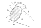
- FIG. 1A is a perspective view showing one form of the medical device 100.
- FIG. 1B is a perspective view showing a usage example of the medical device 100 of FIG. 1A.
- FIG. 2 is an enlarged cross-sectional view showing a part of the cross section taken along the line 2A-2A of FIG. 1A.
- 3 (A) to 3 (C) are plan views showing a shape example of the traction portion 120.
- the diameter of a perfect circle having the same area as the area of the opening of the through hole 112 (the portion of the through hole 112 facing the front surface 113 or the back surface 114) ( The equivalent circle diameter) can be the hole diameter D of the through hole 112.
- the fusion promoting sheet 110 may be provided with the frame portion 110B by not forming the through hole 112 in a certain region including the outer peripheral edge O of the biodegradable sheet which is a constituent material of the fusion promoting portion 110A. Further, after forming a through hole 112 in a certain region including the outer peripheral edge O of the biodegradable sheet which is a constituent material of the fusion promoting portion 110A, only the region is compressed or heated in the thickness direction to penetrate. By crushing the holes 112, a portion in which the constituent materials of the biodegradable sheet are densely assembled may be formed, and the portion may be used as the frame portion 110B.
- FIG. 3 shows an example of the shape of the tow portion 120.
- the traction portion 120A can be composed of a string-shaped member having a wavy outer shape.
- the traction portion 120B is composed of a string-shaped member having a bump-like outer shape (a shape in which convex portions and concave portions are alternately formed along the extending direction). can do.
- the traction portion 120C has an outer shape in which one end edge intersecting the extending direction is formed in a straight line and the other end side is formed in a wavy shape. It can be composed of shaped members.
- FIG. 4A is a perspective view of the medical device 200 according to the modified example 1
- FIG. 4B is a diagram for explaining a shape example of the traction portion 120 of the medical device 200 according to the modified example 1.
- the traction portion 220 included in the medical device 200 according to the first modification is composed of a band-shaped member.
- the traction portion 220 has a connecting portion 221 connected to the frame portion 110B and a non-connecting portion 223 pulled out to the outer side of the fusion promoting sheet 110.
- the non-connecting portion 223 is provided with an adjusting portion 150 composed of an annular portion 223a and an insertion portion 223b inserted through the annular portion 223a.
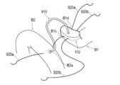
- FIG. 5A is a perspective view for explaining a usage example of the medical device according to the second modification.
- FIG. 6A is a perspective view of the medical device 400 according to the modified example 4.
- the frame portion 410B of the fusion promoting sheet 410 included in the medical device 400 according to the modified example 4 has a plurality of protruding portions 411a, 411b, and 411c arranged in the circumferential direction of the fusion promoting sheet 410.
- Each of the protrusions 411a, 411b, and 411c has a hole 412 through which the traction part 120 can be inserted.
- a predetermined space (gap) g is formed between the protruding portions 411a, 411b, and 411c.
- Each protrusion 411a, 411b, 411c has a substantially triangular planar shape.
- the treatment method according to the present embodiment is applied to the procedure for joining the pancreatic parenchyma B1 and the jejunum B2. Further, in the above treatment method, the periphery of the cut surface B1a of the cut pancreatic parenchyma B1 and the intestinal wall (jejunal serosal muscular layer) of the jejunum B2 are joined. According to this treatment method, the biological tissue of the pancreatic parenchyma B1 and the living body of the intestinal wall of the jejunum B2 are formed by the fusion promoting portion 110A of the fusion promoting sheet 110 sandwiched between the cut surface B1a of the pancreatic parenchyma B1 and the intestinal wall of the jejunum B2. Tissue fusion can be promoted and the risk of suture failure after pancreatic parenchymal-jejunostomy can be reduced.
Abstract
[Problem] To provide a medical device with which the risk of suture failure after an operation such as a surgical operation can be reduced. [Solution] A medical device 100 comprises: a fusion promotion sheet 110 including a fusion promotion part 110A that promotes fusion of biological tissues, and a frame part 110B provided more toward the outside in the surface direction than the fusion promotion part; and a pulling part 120 that is connected to the fusion promotion sheet, and that causes, in accordance with a pulling operation, a second region to deform so as to at least partially cover the outer circumferential surface of a biological organ to be joined.
Description
本発明は、医療デバイスに関する。
The present invention relates to a medical device.
医療の分野において、生体器官を外科的手術により接合する手技(例えば、消化管の吻合術)が知られている。上記のような手技が行われた場合、生体器官同士が接合された接合部における癒合の遅延が生じないことが術後の予後決定因子として重要であることも知られている。
In the medical field, a technique for joining living organs by surgical operation (for example, gastrointestinal anastomosis) is known. It is also known that when the above-mentioned procedure is performed, it is important as a postoperative prognosis determinant that there is no delay in fusion at the joint where the biological organs are joined.
生体器官を接合する手技では種々の方法や医療器具が用いられるが、例えば、生分解性の縫合糸により生体器官を縫合する方法や、ステープラーによる吻合を行う機械式の接合装置(特許文献1を参照)を利用する方法が提案されている。特に、機械式の接合装置を利用して吻合術を行う場合、縫合糸を用いた方法と比較して接合部における生体器官同士の接合力を高めることができるため、縫合不全のリスクを低減させることが可能になる。
Various methods and medical instruments are used in the technique of joining living organs. For example, a method of suturing a living organ with a biodegradable suture and a mechanical joining device for anastomosis with a stapler (Patent Document 1). A method using (see) has been proposed. In particular, when anastomosis is performed using a mechanical joining device, the bonding force between biological organs at the joint can be increased as compared with the method using sutures, which reduces the risk of suture failure. Will be possible.
しかしながら、接合部における癒合の進行の程度は、患者の接合対象部位(被接合部位)における生体組織の状態等にも依存する。そのため、例えば、特許文献1に記載されているような接合装置を使用した場合においても、患者の生体組織の状態如何によっては、縫合不全のリスクを十分に低減させることができない可能性もある。
However, the degree of progression of fusion at the junction also depends on the condition of the living tissue at the junction target site (joint site) of the patient. Therefore, for example, even when a joining device as described in Patent Document 1 is used, the risk of suture failure may not be sufficiently reduced depending on the condition of the patient's living tissue.
そこで本発明は、外科手術等の術後における縫合不全のリスクを低減させることができる医療デバイスを提供することを目的とする。
Therefore, an object of the present invention is to provide a medical device capable of reducing the risk of suture failure after surgery or the like.
本発明の一実施形態に係る医療デバイスは、生体組織の癒合を促進する第1領域と、前記第1領域よりも面方向の外方側に設けられた第2領域と、を備える癒合促進シートと、前記癒合促進シートに接続され、牽引操作に伴って接合対象となる生体器官の外周面の少なくとも一部を覆うように前記第2領域を変形させる牽引部と、を有する。
The medical device according to the embodiment of the present invention is a fusion promoting sheet including a first region for promoting fusion of living tissues and a second region provided on the outer side in the plane direction from the first region. And a traction portion connected to the fusion promoting sheet and deforming the second region so as to cover at least a part of the outer peripheral surface of the biological organ to be joined with the traction operation.
本発明に係る医療デバイスによれば、接合対象となる生体器官の被接合部位の間に癒合促進シートを挟み込ませることにより、生体器官の生体組織の癒合を促進することができる。また、術者は、牽引部を牽引することにより、癒合促進シートの第2領域を、接合対象となる生体器官の外周面の少なくとも一部を覆うように変形させることができる。それにより、術者は、癒合促進シートを生体器官に安定的に保持することができ、手技を実施している間、癒合促進シートがヨレたりズレたりすることを抑制できる。したがって、生体器官の縫合不全のリスクを効果的に低減させることができる。
According to the medical device according to the present invention, it is possible to promote the fusion of the biological tissue of the biological organ by sandwiching the fusion promoting sheet between the bonded sites of the biological organ to be joined. In addition, the surgeon can deform the second region of the fusion promoting sheet so as to cover at least a part of the outer peripheral surface of the biological organ to be joined by pulling the traction portion. As a result, the operator can stably hold the fusion promoting sheet in the biological organ, and can prevent the fusion promoting sheet from being twisted or displaced during the procedure. Therefore, the risk of suture failure of living organs can be effectively reduced.
以下、添付した図面を参照して、本発明の実施形態を説明する。なお、図面の説明において同一の要素には同一の符号を付し、重複する説明を省略する。また、図面の寸法比率は、説明の都合上誇張され、実際の比率とは異なる場合がある。
Hereinafter, embodiments of the present invention will be described with reference to the attached drawings. In the description of the drawings, the same elements are designated by the same reference numerals, and duplicate description will be omitted. In addition, the dimensional ratios in the drawings are exaggerated for convenience of explanation and may differ from the actual ratios.
図1Aは、医療デバイス100の一形態を示す斜視図である。図1Bは、図1Aの医療デバイス100の使用例を示す斜視図である。図2は、図1Aの2A-2A線に沿う断面の一部を拡大して示す断面図である。図3(A)~図3(C)は、牽引部120の形状例を示す平面図である。
FIG. 1A is a perspective view showing one form of the medical device 100. FIG. 1B is a perspective view showing a usage example of the medical device 100 of FIG. 1A. FIG. 2 is an enlarged cross-sectional view showing a part of the cross section taken along the line 2A-2A of FIG. 1A. 3 (A) to 3 (C) are plan views showing a shape example of the traction portion 120.
<医療デバイス100>
図1Aに示すように、医療デバイス100は、接合対象となる生体器官の間に配置される癒合促進シート110と、癒合促進シート110に設けられた牽引部120と、を有する。 <Medical device 100>
As shown in FIG. 1A, themedical device 100 has a fusion promoting sheet 110 arranged between biological organs to be joined, and a traction portion 120 provided on the fusion promoting sheet 110.
図1Aに示すように、医療デバイス100は、接合対象となる生体器官の間に配置される癒合促進シート110と、癒合促進シート110に設けられた牽引部120と、を有する。 <
As shown in FIG. 1A, the
医療デバイス100は、図9~図16に示すように、所定の生体器官同士を接合する手技(例えば、消化管の吻合術)に適用することができる。後述するように、本明細書の説明では、医療デバイス100を使用した手技例として膵実質-空腸吻合術を説明する。
As shown in FIGS. 9 to 16, the medical device 100 can be applied to a procedure for joining predetermined biological organs (for example, anastomosis of the digestive tract). As will be described later, in the description of the present specification, pancreatic parenchymal-jejunal anastomosis will be described as an example of a procedure using the medical device 100.
<癒合促進シート110>
図1Aに示すように、癒合促進シート110は、複数の貫通孔112を有する生分解性シートから形成された生体組織の癒合を促進する癒合促進部(「第1領域」に相当する)110Aを有する。癒合促進部110Aは、癒合促進シート110の面方向の中心部Cを含む所定の範囲に形成されている。 <Union promotion sheet 110>
As shown in FIG. 1A, thefusion promoting sheet 110 includes a fusion promoting portion (corresponding to a “first region”) 110A that promotes fusion of biological tissue formed from a biodegradable sheet having a plurality of through holes 112. Have. The fusion promoting portion 110A is formed in a predetermined range including the central portion C in the plane direction of the fusion promoting sheet 110.
図1Aに示すように、癒合促進シート110は、複数の貫通孔112を有する生分解性シートから形成された生体組織の癒合を促進する癒合促進部(「第1領域」に相当する)110Aを有する。癒合促進部110Aは、癒合促進シート110の面方向の中心部Cを含む所定の範囲に形成されている。 <
As shown in FIG. 1A, the
癒合促進シート110は、癒合促進部110Aよりも癒合促進シート110の面方向の外方側に設けられた枠部(「第2領域」に相当する)110Bを有する。枠部110Bは、癒合促進部110Aの周囲を囲むように、癒合促進シート110の外周縁Oを含む一定の範囲に形成されている。本実施形態では、枠部110Bには貫通孔112が形成されていない。
The fusion promoting sheet 110 has a frame portion (corresponding to a "second region") 110B provided on the outer side in the surface direction of the fusion promoting sheet 110 with respect to the fusion promoting portion 110A. The frame portion 110B is formed in a certain range including the outer peripheral edge O of the fusion promotion sheet 110 so as to surround the periphery of the fusion promotion portion 110A. In the present embodiment, the frame portion 110B is not formed with a through hole 112.
<癒合促進部110A>
癒合促進部110Aに形成された貫通孔112は、図1Aに示すように、癒合促進シート110の面方向において規則的かつ周期的に設けられている。ただし、各貫通孔112は、癒合促進シート110の面方向の各部においてランダムに設けられていてもよい。 <Union Promotion Department 110A>
As shown in FIG. 1A, the throughholes 112 formed in the fusion promoting portion 110A are regularly and periodically provided in the plane direction of the fusion promoting sheet 110. However, each through hole 112 may be randomly provided at each portion in the surface direction of the fusion promoting sheet 110.
癒合促進部110Aに形成された貫通孔112は、図1Aに示すように、癒合促進シート110の面方向において規則的かつ周期的に設けられている。ただし、各貫通孔112は、癒合促進シート110の面方向の各部においてランダムに設けられていてもよい。 <
As shown in FIG. 1A, the through
各貫通孔112は、図2に示すように、癒合促進シート110の厚み方向(図2の上下方向)に沿って表面113と裏面114との間で略垂直に延びている。なお、各貫通孔112は、癒合促進シート110の厚み方向に沿う断面において、表面113と裏面114との間でジグザグ状に屈曲していたり、湾曲していたりしてもよい。
As shown in FIG. 2, each through hole 112 extends substantially vertically between the front surface 113 and the back surface 114 along the thickness direction of the fusion promoting sheet 110 (vertical direction in FIG. 2). In addition, each through hole 112 may be bent or curved in a zigzag shape between the front surface 113 and the back surface 114 in the cross section along the thickness direction of the fusion promoting sheet 110.
各貫通孔112は、略円形の平面形状(癒合促進シート110の表面113又は癒合促進シート110の裏面114を平面視した際の形状)を有する。ただし、各貫通孔112の平面形状は、特に限定されず、例えば、楕円形や多角形(矩形や三角形等)であってもよい。また、貫通孔112ごとに平面形状や断面形状が異なっていてもよい。
Each through hole 112 has a substantially circular planar shape (shape when the front surface 113 of the fusion promotion sheet 110 or the back surface 114 of the fusion promotion sheet 110 is viewed in a plan view). However, the planar shape of each through hole 112 is not particularly limited, and may be, for example, an ellipse or a polygon (rectangle, triangle, etc.). Further, the plane shape and the cross-sectional shape may be different for each through hole 112.
癒合促進シート110は、略円形の平面形状を有する。ただし、癒合促進シート110の平面形状は、特に限定されず、例えば、楕円形や多角形(矩形や三角形等)であってもよい。
The fusion promoting sheet 110 has a substantially circular planar shape. However, the planar shape of the fusion promoting sheet 110 is not particularly limited, and may be, for example, an ellipse or a polygon (rectangle, triangle, etc.).
癒合促進シート110の厚み(図2に示す寸法T)は特に制限されないが、好ましくは0.05~0.3mmであり、より好ましくは0.1~0.2mmである。癒合促進シート110の厚みが0.05mm以上である場合(特に0.1mm以上である場合)、癒合促進シート110の取り扱い時に癒合促進部110Aが破損しない程度の強度を備えさせることができる。一方、癒合促進シート110の厚みが0.3mm以下である場合(特に0.2mm以下である場合)、癒合促進シート110が適用される生体組織に癒合促進部110Aが密着して生体組織に追随するのに十分な柔軟性を備えさせることができる。
The thickness of the fusion promoting sheet 110 (dimension T shown in FIG. 2) is not particularly limited, but is preferably 0.05 to 0.3 mm, more preferably 0.1 to 0.2 mm. When the thickness of the fusion promoting sheet 110 is 0.05 mm or more (particularly when it is 0.1 mm or more), the fusion promoting portion 110A can be provided with such strength that the fusion promoting portion 110A is not damaged when the fusion promoting sheet 110 is handled. On the other hand, when the thickness of the fusion promoting sheet 110 is 0.3 mm or less (particularly when it is 0.2 mm or less), the fusion promoting portion 110A adheres to the living tissue to which the fusion promoting sheet 110 is applied and follows the living tissue. It can be flexible enough to do so.
癒合促進部110Aは、貫通孔112のピッチP(図2に示す距離Pであり、隣接する貫通孔112の間の距離)に対する貫通孔112の孔径D(図2に示す距離D)の比の値が、0.25以上40未満であることが好ましい。なお、貫通孔112の平面形状が真円である場合、貫通孔112の孔径Dは真円の直径に等しくなる。一方、貫通孔112の平面形状が真円ではない場合には、貫通孔112の開口部(貫通孔112において表面113又は裏面114に面した部分)の面積と同じ面積を有する真円の直径(円相当径)を当該貫通孔112の孔径Dとすることができる。
The fusion promoting portion 110A is the ratio of the hole diameter D (distance D shown in FIG. 2) of the through hole 112 to the pitch P (distance P shown in FIG. 2 and the distance between adjacent through holes 112) of the through hole 112. The value is preferably 0.25 or more and less than 40. When the planar shape of the through hole 112 is a perfect circle, the hole diameter D of the through hole 112 is equal to the diameter of the perfect circle. On the other hand, when the planar shape of the through hole 112 is not a perfect circle, the diameter of a perfect circle having the same area as the area of the opening of the through hole 112 (the portion of the through hole 112 facing the front surface 113 or the back surface 114) ( The equivalent circle diameter) can be the hole diameter D of the through hole 112.
癒合促進部110Aは、複数の貫通孔112を有するため、各貫通孔112に対応する孔径Dの値が複数存在する。そこで、本実施形態では、上述した比の値を算出するにあたっては、複数の貫通孔112にそれぞれ対応する孔径Dの値の2点以上の算術平均値を孔径Dの代表値として用いるものとする。一方、複数の貫通孔112のピッチPは、2つの貫通孔112の開口部同士の最短距離で定義する。ただし、ピッチPの値についても隣接する貫通孔112の組み合わせに対応するピッチPの値が複数存在する。したがって、本実施形態では、上述した比の値を算出するにあたっては、隣接する貫通孔112の組み合わせにそれぞれ対応するピッチPの値の2点以上の算術平均値をピッチPの代表値として用いるものとする。
Since the fusion promoting unit 110A has a plurality of through holes 112, there are a plurality of values of the hole diameter D corresponding to each through hole 112. Therefore, in the present embodiment, in calculating the above-mentioned ratio value, the arithmetic mean value of two or more points of the hole diameter D values corresponding to the plurality of through holes 112 is used as the representative value of the hole diameter D. .. On the other hand, the pitch P of the plurality of through holes 112 is defined by the shortest distance between the openings of the two through holes 112. However, as for the value of the pitch P, there are a plurality of values of the pitch P corresponding to the combination of the adjacent through holes 112. Therefore, in the present embodiment, in calculating the above-mentioned ratio value, the arithmetic mean value of two or more points of the pitch P values corresponding to the combinations of the adjacent through holes 112 is used as the representative value of the pitch P. And.
なお、上記の貫通孔112のピッチP、孔径D、ピッチPに対する孔径Dの比等は、一例であり、これに限定されることはない。
The pitch P, the hole diameter D, the ratio of the hole diameter D to the pitch P, and the like of the through hole 112 are merely examples, and are not limited thereto.
癒合促進部110Aは、生分解性の材料で構成することができる。癒合促進部110Aの構成材料について特に制限はなく、例えば、生分解性樹脂が挙げられる。生分解性樹脂としては、例えば、特表2011-528275号公報、特表2008-514719号公報、国際公報第2008-1952号、特表2004-509205号公報等に記載されるものなどの公知の生分解性(共)重合体が使用できる。具体的には、(1)脂肪族ポリエステル、ポリエステル、ポリ酸無水物、ポリオルソエステル、ポリカーボネート、ポリホスファゼン、ポリリン酸エステル、ポリビニルアルコール、ポリペプチド、多糖、タンパク質、セルロースからなる群から選択される重合体;(2)上記(1)を構成する一以上の単量体から構成される共重合体などが挙げられる。すなわち、生分解性シートは、脂肪族ポリエステル、ポリエステル、ポリ酸無水物、ポリオルソエステル、ポリカーボネート、ポリホスファゼン、ポリリン酸エステル、ポリビニルアルコール、ポリペプチド、多糖、タンパク質、セルロースからなる群から選択される重合体、ならびに前記重合体を構成する一以上の単量体から構成される共重合体からなる群より選択される少なくとも一種の生分解性樹脂を含むことが好ましい。
The fusion promoting unit 110A can be made of a biodegradable material. The constituent material of the fusion promoting unit 110A is not particularly limited, and examples thereof include biodegradable resins. As the biodegradable resin, for example, those described in Japanese Patent Publication No. 2011-528275, Japanese Patent Publication No. 2008-514719, International Publication No. 2008-1952, Japanese Patent Publication No. 2004-509205 and the like are known. Biodegradable (co) polymers can be used. Specifically, it is selected from the group consisting of (1) aliphatic polyester, polyester, polyacid anhydride, polyorthoester, polycarbonate, polyphosphazene, polyphosphate ester, polyvinyl alcohol, polypeptide, polysaccharide, protein, and cellulose. Polymer; (2) A copolymer composed of one or more monomers constituting the above (1) and the like can be mentioned. That is, the biodegradable sheet is selected from the group consisting of aliphatic polyesters, polyesters, polyacid anhydrides, polyorthoesters, polycarbonates, polyphosphazenes, polyphosphates, polyvinyl alcohols, polypeptides, polysaccharides, proteins, and celluloses. It preferably contains at least one biodegradable resin selected from the group consisting of a polymer and a copolymer composed of one or more monomers constituting the polymer.
癒合促進部110Aの製造方法は特に限定されないが、例えば、上述した生分解性樹脂からなる繊維を作製し、当該繊維を用いてメッシュ形状のシートを製造する方法が挙げられる。生分解性樹脂からなる繊維を作製する方法としては、特に限定されないが、例えば、エレクトロスピニング法(電界紡糸法・静電紡糸法)や、メルトブロー法等が挙げられる。癒合促進部110Aは、上記の方法のうち1種のみを選択して用いてもよいし、2種以上を選択し適宜組み合わせてもよい。なお、癒合促進部110Aの製造方法のさらに別の例として、上述した生分解性樹脂からなる繊維を常法に従って紡糸し、得られた繊維をメッシュ状に編むことによって本発明に係る生分解性シートを製造してもよい。
The method for producing the fusion promoting unit 110A is not particularly limited, and examples thereof include a method for producing a fiber made of the above-mentioned biodegradable resin and producing a mesh-shaped sheet using the fiber. The method for producing the fiber made of a biodegradable resin is not particularly limited, and examples thereof include an electrospinning method (electrospinning method / electrostatic spinning method) and a melt blow method. As the fusion promoting unit 110A, only one of the above methods may be selected and used, or two or more of the above methods may be selected and appropriately combined. As yet another example of the method for producing the fusion promoting unit 110A, the fibers made of the above-mentioned biodegradable resin are spun according to a conventional method, and the obtained fibers are knitted into a mesh shape to obtain the biodegradable property according to the present invention. Sheets may be manufactured.
癒合促進部110Aは、癒合促進部110Aを構成する生分解性樹脂等の構成材料によって生体反応を惹起させる。癒合促進部110Aは、この作用により、フィブリン等の生体成分の発現を誘導する。このようにして誘導された生体成分は、癒合促進部110Aの貫通孔112を貫通するようにして集積することで、癒合を促進することができる。したがって、接合対象となる生体器官同士の間に癒合促進部110Aを配置することにより、上記のメカニズムによる癒合の促進が生じる。
The fusion promoting unit 110A induces a biological reaction by a constituent material such as a biodegradable resin constituting the fusion promoting unit 110A. The fusion promoting unit 110A induces the expression of biological components such as fibrin by this action. The biological components induced in this way can promote fusion by accumulating so as to penetrate through the through hole 112 of the fusion promoting portion 110A. Therefore, by arranging the fusion promoting portion 110A between the biological organs to be joined, the fusion is promoted by the above mechanism.
なお、癒合促進部110Aの材質は、生体器官の癒合を促進させることが可能であれば、生分解性でなくてもよい。また、癒合促進部110Aは、生体器官の癒合を促進させることが可能であれば、材質に関わらず、貫通孔112が形成されていなくてもよい。
The material of the fusion promoting unit 110A does not have to be biodegradable as long as it can promote the fusion of biological organs. Further, the fusion promoting unit 110A may not have the through hole 112 formed regardless of the material, as long as it can promote the fusion of living organs.
<枠部110B>
図1Aに示すように、枠部110Bは、癒合促進部110Aの周囲を取り囲むように癒合促進シート110に形成されている。枠部110Bは、外力付加時の変形が容易に生じないように、癒合促進部110Aよりも大きな剛性を備えるように形成されていることが好ましい。枠部110Bは、例えば、貫通孔112のような孔部が形成されていない生分解性シート、癒合促進部110Aよりも高い剛性を備える樹脂製のシートや不織布で構成することができる。 <Framepart 110B>
As shown in FIG. 1A, theframe portion 110B is formed on the fusion promoting sheet 110 so as to surround the fusion promoting portion 110A. The frame portion 110B is preferably formed to have a higher rigidity than the fusion promoting portion 110A so that the frame portion 110B is not easily deformed when an external force is applied. The frame portion 110B can be made of, for example, a biodegradable sheet in which a hole such as a through hole 112 is not formed, a resin sheet having a higher rigidity than the fusion promoting portion 110A, or a non-woven fabric.
図1Aに示すように、枠部110Bは、癒合促進部110Aの周囲を取り囲むように癒合促進シート110に形成されている。枠部110Bは、外力付加時の変形が容易に生じないように、癒合促進部110Aよりも大きな剛性を備えるように形成されていることが好ましい。枠部110Bは、例えば、貫通孔112のような孔部が形成されていない生分解性シート、癒合促進部110Aよりも高い剛性を備える樹脂製のシートや不織布で構成することができる。 <Frame
As shown in FIG. 1A, the
また、癒合促進部110Aの構成材料となる生分解性シートの外周縁Oを含む一定の領域に貫通孔112を形成しないことにより、癒合促進シート110に枠部110Bを設けてもよい。また、癒合促進部110Aの構成材料となる生分解性シートの外周縁Oを含む一定の領域に貫通孔112を形成した後、当該領域のみを厚み方向に圧縮したり加熱したりして、貫通孔112を押し潰すことにより、生分解性シートの構成材料が密に集合した部分を形成して、当該部分を枠部110Bとしてもよい。
Further, the fusion promoting sheet 110 may be provided with the frame portion 110B by not forming the through hole 112 in a certain region including the outer peripheral edge O of the biodegradable sheet which is a constituent material of the fusion promoting portion 110A. Further, after forming a through hole 112 in a certain region including the outer peripheral edge O of the biodegradable sheet which is a constituent material of the fusion promoting portion 110A, only the region is compressed or heated in the thickness direction to penetrate. By crushing the holes 112, a portion in which the constituent materials of the biodegradable sheet are densely assembled may be formed, and the portion may be used as the frame portion 110B.
また、枠部110Bは、その少なくとも一部に、生体器官との癒着を抑制する抑制部を備えていてもよい。抑制部を構成する材料としては、生体器官との癒着を抑制できる限りにおいて特に限定されないが、例えば、不織布を用いることができる。また、抑制部は、癒合促進部110Aと同様に、生分解性の材料で構成することができる。
Further, the frame portion 110B may be provided with an inhibitory portion that suppresses adhesion with a biological organ at least in a part thereof. The material constituting the suppressing portion is not particularly limited as long as it can suppress adhesion with a living organ, but for example, a non-woven fabric can be used. Further, the suppressing portion can be made of a biodegradable material, similarly to the fusion promoting portion 110A.
なお、癒合促進シート110における癒合促進部110Aと枠部110Bの面積比、平面視における癒合促進部110A及び枠部110Bの形状等は特に限定されない。
The area ratio of the fusion promoting portion 110A and the frame portion 110B in the fusion promoting sheet 110, the shapes of the fusion promoting portion 110A and the frame portion 110B in a plan view, and the like are not particularly limited.
<牽引部120>
図1A、図1Bに示すように、医療デバイス100は、癒合促進シート110に接続され、牽引操作に伴って接合対象となる膵実質B1の外周面の少なくとも一部を覆うように枠部110Bを変形させる牽引部120を有する。 <Towingpart 120>
As shown in FIGS. 1A and 1B, themedical device 100 is connected to the fusion promoting sheet 110, and the frame portion 110B is covered with at least a part of the outer peripheral surface of the pancreatic parenchyma B1 to be joined by the traction operation. It has a traction portion 120 to be deformed.
図1A、図1Bに示すように、医療デバイス100は、癒合促進シート110に接続され、牽引操作に伴って接合対象となる膵実質B1の外周面の少なくとも一部を覆うように枠部110Bを変形させる牽引部120を有する。 <Towing
As shown in FIGS. 1A and 1B, the
牽引部120は、所定の長さを有する紐状の部材で構成している。牽引部120は、枠部110Bに接続された接続部121と、枠部110Bとは接続されておらず、かつ、癒合促進シート110の外方側へ引き出された非接続部123と、を有する。
The tow portion 120 is composed of a string-shaped member having a predetermined length. The traction portion 120 has a connecting portion 121 connected to the frame portion 110B and a non-connecting portion 123 that is not connected to the frame portion 110B and is pulled out to the outer side of the fusion promoting sheet 110. ..
牽引部120の接続部121は、癒合促進シート110の内部を挿通している。癒合促進シート110の内部には、接続部121が摺動可能に挿通された空間(図示省略)が形成されている。本実施形態では、牽引部120は、図1Bに示すように、癒合促進シート110において非接続部123を牽引した際に、癒合促進シート110の枠部110Bが内部に空間を備える袋(巾着袋)の開口部を構成するように癒合促進シート110に配置されている。術者は、牽引部120の非接続部123の牽引量を調整することにより、癒合促進シート110で構成される袋の開口部の開口面積を調整することができる。
The connecting portion 121 of the traction portion 120 is inserted through the inside of the fusion promoting sheet 110. Inside the fusion promoting sheet 110, a space (not shown) into which the connecting portion 121 is slidably inserted is formed. In the present embodiment, as shown in FIG. 1B, the traction portion 120 is a bag (drawstring bag) in which the frame portion 110B of the fusion promotion sheet 110 has a space inside when the non-connection portion 123 is pulled by the fusion promotion sheet 110. ) Is arranged on the fusion promoting sheet 110 so as to form an opening. The surgeon can adjust the opening area of the opening of the bag made of the fusion promoting sheet 110 by adjusting the traction amount of the non-connecting portion 123 of the traction portion 120.
牽引部120を癒合促進シート110に取り付ける具体的な方法は特に限定されない。また、牽引部120は、癒合促進シート110から分離できるように構成したり、癒合促進シート110と別部材で後付け可能に構成したりしてもよい。
The specific method of attaching the traction portion 120 to the fusion promotion sheet 110 is not particularly limited. Further, the traction portion 120 may be configured to be separable from the fusion promoting sheet 110, or may be configured to be retrofitted with a member separate from the fusion promoting sheet 110.
牽引部120は、癒合促進シート110の周方向に沿う半分以上の長さで枠部110Bに配置されている。本実施形態では、図1Bに示すように、接続部121は、膵実質B1の後壁B1c(膵実質B1の周方向の背側の部分)側の対応する箇所に配置している。非接続部123は、癒合促進シート110の膵実質B1の前壁B1d(膵実質B1の周方向の腹側の部分)の対応する箇所に配置している。ただし、牽引部120の接続部121を癒合促進シート110に配置する位置は特に限定されない。
The traction portion 120 is arranged in the frame portion 110B with a length of more than half along the circumferential direction of the fusion promotion sheet 110. In the present embodiment, as shown in FIG. 1B, the connecting portion 121 is arranged at the corresponding portion on the rear wall B1c (the dorsal portion in the circumferential direction of the pancreatic parenchyma B1) side of the pancreatic parenchyma B1. The non-connecting portion 123 is arranged at a corresponding portion of the anterior wall B1d of the pancreatic parenchyma B1 (the ventral portion in the circumferential direction of the pancreatic parenchyma B1) of the fusion promoting sheet 110. However, the position where the connecting portion 121 of the traction portion 120 is arranged on the fusion promoting sheet 110 is not particularly limited.
医療デバイス100は、牽引部120の牽引操作を制限することにより、枠部110Bの変形量を調整可能にする調整部150を有する。本実施形態では、調整部150は、非接続部123の一部である環状部123aと、環状部123aを挿通する挿通部123bにより構成している。非接続部123の一部に凹凸形状や切れ込み等(図3や図4に示す構造等)を付加して、非接続部123を環状部123aに引っ掛けて嵌合させることにより牽引部120の牽引操作を制限することができる。また、上記のように構成することにより、調整部150は、術者が手指等により牽引部120を牽引した状態を維持することなく、自動的に牽引された状態を維持するロック機構160としての機能も有する。なお、調整部150やロック機構160は、例えば、牽引部120とは別部材で構成された固定用の部材等で構成することも可能である。また、非接続部123は、その少なくとも一部が、環状部123aを通過できないような構成となっていてもよい。
The medical device 100 has an adjusting unit 150 that can adjust the amount of deformation of the frame portion 110B by limiting the traction operation of the traction unit 120. In the present embodiment, the adjusting portion 150 is composed of an annular portion 123a which is a part of the non-connecting portion 123 and an insertion portion 123b through which the annular portion 123a is inserted. The traction portion 120 is towed by adding an uneven shape, a notch, or the like (structure shown in FIGS. 3 or 4) to a part of the non-connection portion 123, and hooking the non-connection portion 123 on the annular portion 123a to fit the non-connection portion 123. Operations can be restricted. Further, by configuring as described above, the adjusting unit 150 serves as a lock mechanism 160 that automatically maintains the towed state without maintaining the towed part 120 by the operator with fingers or the like. It also has a function. The adjusting unit 150 and the locking mechanism 160 may be composed of, for example, a fixing member that is different from the traction unit 120. Further, the non-connecting portion 123 may be configured so that at least a part thereof cannot pass through the annular portion 123a.
牽引部120は、例えば、塩化ビニル、ポリウレタンエラストマー、ポリスチレンエラストマー、スチレンーエチレンーブチレンースチレン共重合体(SEBS)、スチレンーエチレンープロピレンースチレン共重合体(SEPS)などの熱可塑性エラストマー、ナイロン、PETなどの熱可塑性樹脂、又はゴム、シリコーンエラストマー、繊維素材、SUS線、銅線、チタン線、ナイチノール線などの金属等で構成することができる。また、牽引部120は、例えば、癒合促進部110Aと同様の材料で構成することもできる。癒合促進部110Aと同様の材料で構成することにより、癒合促進部110Aと同一の製造現場で製造することが可能になるため、製造作業が容易なものとなる。
The traction portion 120 is, for example, a thermoplastic elastomer such as vinyl chloride, polyurethane elastomer, polystyrene elastomer, styrene-ethylene-butylene-styrene copolymer (SEBS), styrene-ethylene-propylene-styrene copolymer (SEPS), nylon. , PET or other thermoplastic resin, or rubber, silicone elastomer, fiber material, SUS wire, copper wire, titanium wire, nitinol wire or other metal or the like. Further, the traction portion 120 can be made of, for example, the same material as the fusion promoting portion 110A. By using the same material as the fusion promoting unit 110A, it becomes possible to manufacture at the same manufacturing site as the fusion promoting unit 110A, so that the manufacturing operation becomes easy.
図3には、牽引部120の形状例を示している。図3(A)に示すように、例えば、牽引部120Aは波状の外形を有する紐状の部材で構成することができる。また、図3(B)に示すように、例えば、牽引部120Bは、コブ状(延在方向に沿って凸部と凹部が交互に形成された形状)の外形を有する紐状の部材で構成することができる。また、図3(C)に示すように、牽引部120Cは、延在方向と交差する一側の端辺が直線状に形成され、他側の端辺が波状に形成された外形を有する紐状の部材で構成することができる。例えば、牽引部120A及び牽引部120Bを伸縮性の材料で構成することにより、牽引操作した際には直線状に変形させることができ、牽引操作を解除した際には元の形状に戻るように構成することができる。このように構成することにより、各牽引部120A、120Bを牽引した際に、各牽引部120A,120Bと癒合促進シート110との間の摩擦を低減させることができ、癒合促進シート110が破損することを防止できる。また、図3(C)に示す牽引部120Cは、延在方向と交差する一側の端辺が直線状に形成されているため、癒合促進シート110との間の摩擦をより一層低減させることができる。
FIG. 3 shows an example of the shape of the tow portion 120. As shown in FIG. 3A, for example, the traction portion 120A can be composed of a string-shaped member having a wavy outer shape. Further, as shown in FIG. 3B, for example, the traction portion 120B is composed of a string-shaped member having a bump-like outer shape (a shape in which convex portions and concave portions are alternately formed along the extending direction). can do. Further, as shown in FIG. 3C, the traction portion 120C has an outer shape in which one end edge intersecting the extending direction is formed in a straight line and the other end side is formed in a wavy shape. It can be composed of shaped members. For example, by forming the traction portion 120A and the traction portion 120B with an elastic material, it can be deformed linearly when the traction operation is performed, and returns to the original shape when the traction operation is released. Can be configured. With this configuration, when the pulling portions 120A and 120B are towed, the friction between the pulling portions 120A and 120B and the fusion promoting sheet 110 can be reduced, and the fusion promoting sheet 110 is damaged. Can be prevented. Further, since the traction portion 120C shown in FIG. 3C is formed with a linear end side on one side intersecting the extending direction, the friction with the fusion promoting sheet 110 can be further reduced. Can be done.
なお、後述するように、牽引部220は、帯状の部材(図4A、図4Bを参照)で構成することもできる。本明細書では、帯状の部材は、紐状の部材よりも断面積が大きく形成されたものと定義することができる。帯状の部材の一例として、断面形状に長辺と短辺が形成されたものを挙げることができるが、これに限定されることはない。
As will be described later, the traction portion 220 can also be composed of a strip-shaped member (see FIGS. 4A and 4B). In the present specification, the strip-shaped member can be defined as having a larger cross-sectional area than the string-shaped member. As an example of the strip-shaped member, a member having a long side and a short side formed in a cross-sectional shape can be mentioned, but the cross-sectional shape is not limited to this.
図1Bには、癒合促進シート110を膵実質Baに配置した際の様子を示している。術者は、癒合促進シート110の癒合促進部110Aを膵実質Baの切断面B1aに重ねるように配置する。この際、術者は、牽引部120の非接続部123を膵実質B1の前壁B1d(膵実質B1の周方向の腹側の部分)側に配置する。術者は、膵実質B1の前壁B1d側で膵実質B1から離間する方向へ向けて牽引部120を牽引することにより、枠部110Bを変形させる。癒合促進シート110は、牽引部120が牽引されると、膵実質B1の外周面の一部を覆うように袋状に変形する。術者が牽引部120を所定の長さだけ牽引すると、調整部150により以降の牽引操作が制限される。これにより、膵実質B1が牽引部120により過度に締め付けられることを防止できる。癒合促進シート110が膵実質B1を覆うように変形することにより、癒合促進シート110を膵実質B1に安定的に保持させることが可能になる。
FIG. 1B shows a state when the fusion promoting sheet 110 is placed on the pancreatic parenchyma Ba. The surgeon arranges the fusion promoting portion 110A of the fusion promoting sheet 110 so as to overlap the cut surface B1a of the pancreatic parenchyma Ba. At this time, the operator arranges the non-connecting portion 123 of the traction portion 120 on the anterior wall B1d (the ventral portion in the circumferential direction of the pancreatic parenchyma B1) side of the pancreatic parenchyma B1. The operator deforms the frame portion 110B by pulling the traction portion 120 on the anterior wall B1d side of the pancreatic parenchyma B1 in a direction away from the pancreatic parenchyma B1. When the traction portion 120 is pulled, the fusion promoting sheet 110 is deformed into a bag shape so as to cover a part of the outer peripheral surface of the pancreatic parenchyma B1. When the operator pulls the traction unit 120 by a predetermined length, the adjustment unit 150 limits the subsequent traction operation. This makes it possible to prevent the pancreatic parenchyma B1 from being excessively tightened by the traction portion 120. By deforming the fusion promoting sheet 110 so as to cover the pancreatic parenchyma B1, the fusion promoting sheet 110 can be stably held by the pancreatic parenchyma B1.
以上説明したように、本実施形態に係る医療デバイス100は、複数の貫通孔112を有する生分解性シートから形成された生体組織の癒合を促進する癒合促進部110Aと、癒合促進部110Aよりも面方向の外方側に設けられた枠部110Bと、を備える癒合促進シート110と、癒合促進シート110に接続され、牽引操作に伴って接合対象となる生体器官の外周面の少なくとも一部を覆うように枠部110Bを変形させる牽引部120と、を有する。
As described above, the medical device 100 according to the present embodiment has a fusion promoting unit 110A that promotes fusion of biological tissues formed from a biodegradable sheet having a plurality of through holes 112, and a fusion promoting unit 110A. A fusion promoting sheet 110 including a frame portion 110B provided on the outer side in the surface direction, and at least a part of the outer peripheral surface of a biological organ connected to the fusion promoting sheet 110 and to be joined by a traction operation. It has a traction portion 120 that deforms the frame portion 110B so as to cover it.
上記のように構成された医療デバイス100によれば、接合対象となる生体器官の被接合部位の間に癒合促進シート110を挟み込ませることにより、生体器官の生体組織の癒合を促進することができる。また、術者は、牽引部120を牽引することにより、癒合促進シート110の枠部110Bを、接合対象となる生体器官の外周面の少なくとも一部を覆うように変形させることができる。それにより、術者は、癒合促進シート110を生体器官に安定的に保持することができ、手技を実施している間、癒合促進シート110がヨレたりズレたりすることを抑制できる。したがって、生体器官の縫合不全のリスクを効果的に低減させることができる。
According to the medical device 100 configured as described above, the fusion of the biological tissues of the biological organs can be promoted by sandwiching the fusion promoting sheet 110 between the bonded sites of the biological organs to be joined. .. Further, by pulling the traction portion 120, the operator can deform the frame portion 110B of the fusion promoting sheet 110 so as to cover at least a part of the outer peripheral surface of the biological organ to be joined. As a result, the surgeon can stably hold the fusion promoting sheet 110 in the living organ, and can prevent the fusion promoting sheet 110 from being twisted or displaced during the procedure. Therefore, the risk of suture failure of living organs can be effectively reduced.
また、牽引部120は、枠部110Bに接続された接続部121と、枠部110Bとは接続されておらず、かつ、癒合促進シート110の外方側へ引き出された非接続部123と、を有する。そのため、術者は、非接続部123を牽引する簡単な操作により、生体器官の外周面を覆うように枠部110Bを変形させることができる。
Further, the traction portion 120 includes a connecting portion 121 connected to the frame portion 110B, a non-connecting portion 123 that is not connected to the frame portion 110B and is pulled out to the outer side of the fusion promoting sheet 110. Has. Therefore, the operator can deform the frame portion 110B so as to cover the outer peripheral surface of the living organ by a simple operation of pulling the non-connecting portion 123.
また、接続部121は、癒合促進シート110の周方向に沿う半分以上の長さで枠部110Bと接続されている。そのため、術者は、牽引部120を牽引することにより、癒合促進シート110をより確実に所望の形状に変形させることができる。
Further, the connecting portion 121 is connected to the frame portion 110B with a length of more than half along the circumferential direction of the fusion promoting sheet 110. Therefore, the operator can more reliably deform the fusion promoting sheet 110 into a desired shape by pulling the traction portion 120.
また、牽引部120は、所定の長さを有する紐状の部材で構成されている。そのため、術者は、牽引部120を牽引することにより、癒合促進シート110を所望の形状に容易に変形させることができる。
Further, the traction portion 120 is composed of a string-shaped member having a predetermined length. Therefore, the operator can easily deform the fusion promoting sheet 110 into a desired shape by pulling the traction portion 120.
また、医療デバイス100は、牽引部120の牽引操作を制限することにより、枠部110Bの変形量を調整可能にする調整部150を有する。そのため、術者は、牽引部120により生体器官が過剰に締め付けられることを防止できる。
Further, the medical device 100 has an adjusting unit 150 that makes it possible to adjust the amount of deformation of the frame portion 110B by limiting the traction operation of the traction unit 120. Therefore, the operator can prevent the living organ from being excessively tightened by the traction portion 120.
また、枠部110Bは、生体器官との癒着を抑制する抑制部により、接合される生体器官以外の生体器官に、枠部110Bが癒着することを防止することができる。
Further, the frame portion 110B can prevent the frame portion 110B from adhering to a biological organ other than the biological organ to be joined by the suppressing portion that suppresses the adhesion to the biological organ.
次に、上述した実施形態の変形例を説明する。変形例の説明では、前述した実施形態で既に説明した構成部材等についての詳細な説明は省略する。また、変形例の説明で特に説明がない内容については、前述した実施形態と同一のものとすることができる。
Next, a modified example of the above-described embodiment will be described. In the description of the modified example, detailed description of the constituent members and the like already described in the above-described embodiment will be omitted. In addition, the contents that are not particularly explained in the description of the modified example can be the same as those in the above-described embodiment.
<変形例1>
図4Aは、変形例1に係る医療デバイス200の斜視図、図4Bは、変形例1に係る医療デバイス200の牽引部120の形状例を説明するための図である。 <Modification example 1>
FIG. 4A is a perspective view of themedical device 200 according to the modified example 1, and FIG. 4B is a diagram for explaining a shape example of the traction portion 120 of the medical device 200 according to the modified example 1.
図4Aは、変形例1に係る医療デバイス200の斜視図、図4Bは、変形例1に係る医療デバイス200の牽引部120の形状例を説明するための図である。 <Modification example 1>
FIG. 4A is a perspective view of the
図4Aに示すように、変形例1に係る医療デバイス200が備える牽引部220は、帯状の部材で構成している。牽引部220は、枠部110Bに接続された接続部221と、癒合促進シート110の外方側に引き出された非接続部223と、を有する。非接続部223には、環状部223aと環状部223aに挿通された挿通部223bとで構成される調整部150が設けられている。
As shown in FIG. 4A, the traction portion 220 included in the medical device 200 according to the first modification is composed of a band-shaped member. The traction portion 220 has a connecting portion 221 connected to the frame portion 110B and a non-connecting portion 223 pulled out to the outer side of the fusion promoting sheet 110. The non-connecting portion 223 is provided with an adjusting portion 150 composed of an annular portion 223a and an insertion portion 223b inserted through the annular portion 223a.
図4B(A)に示すように、牽引部220は、略一定の幅で直線状に延びる帯状の部材で構成することができる。また、図4B(B)に示すように、牽引部220Aは、延在方向の略中央部分に形成され、延在方向と交差する幅方向に突出した凸部225を有する帯状の部材で構成することができる。牽引部220Aは、牽引部220よりも癒合促進シート110を生体器官に対して保持する保持力を高めることができる。また、図4(C)に示すように、牽引部220Bは、延在方向の略中央部分に向けて幅が徐々に大きくなる形状で形成された帯状の部材で構成することができる。牽引部220Bは、牽引部220Bが癒合促進シート110から取り外し可能に構成される場合に、癒合促進シート110に対する挿通(接続)が解除され易くなる。また、図4B(D)、図4B(E)に示すように、各牽引部220C、220Dの幅方向の両端部226と中央部227とで剛性を異なるように構成してもよい。各牽引部220C、220Dの一部の剛性を他の部分よりも大きく形成することにより、牽引操作の際、各牽引部220C、220Dが破損することを防止できる。また、図4B(F)に示すように、牽引部220Eには、幅方向に延びるスリット228a、228bや、幅方向の中央部分に形成された延在方向に延びる孔部229を設けることもできる。術者は、孔部229に牽引部220Eを通して、牽引部220Eの側面部をスリット227a、228bに引っ掛けることにより、牽引部220Eの牽引操作を規制することが可能になる。なお、帯状の部材で構成された各牽引部は、図3に示した紐状部材の形状例と同様の平面形状で構成することもできる。
As shown in FIG. 4B (A), the traction portion 220 can be composed of a strip-shaped member extending linearly with a substantially constant width. Further, as shown in FIG. 4B (B), the traction portion 220A is formed of a strip-shaped member formed at a substantially central portion in the extending direction and having a convex portion 225 protruding in the width direction intersecting the extending direction. be able to. The traction portion 220A can have a higher holding force for holding the fusion promoting sheet 110 against the living organ than the traction portion 220. Further, as shown in FIG. 4C, the traction portion 220B can be formed of a strip-shaped member formed in a shape in which the width gradually increases toward a substantially central portion in the extending direction. When the traction portion 220B is configured to be removable from the fusion promotion sheet 110, the traction portion 220B is likely to be disconnected (connected) to the fusion promotion sheet 110. Further, as shown in FIGS. 4B (D) and 4B (E), the rigidity may be different between the both end portions 226 and the central portion 227 in the width direction of the traction portions 220C and 220D. By forming a part of the traction portions 220C and 220D to have a higher rigidity than the other portions, it is possible to prevent the traction portions 220C and 220D from being damaged during the traction operation. Further, as shown in FIG. 4B (F), the traction portion 220E may be provided with slits 228a and 228b extending in the width direction and a hole portion 229 formed in the central portion in the width direction and extending in the extending direction. .. The operator can regulate the pulling operation of the pulling portion 220E by passing the pulling portion 220E through the hole portion 229 and hooking the side surface portion of the pulling portion 220E into the slits 227a and 228b. It should be noted that each traction portion made of the strip-shaped member can also be formed in a planar shape similar to the shape example of the string-shaped member shown in FIG.
医療デバイス200は、牽引部220が帯状の部材で構成されているため、牽引部220が紐状の部材で構成されている場合と比較して、牽引部220と膵実質B1との接触面積が大きくなる。したがって、医療デバイス200は、膵実質B1に対する癒合促進シート110の保持力を高めることができる。
In the medical device 200, since the traction portion 220 is composed of a band-shaped member, the contact area between the traction portion 220 and the pancreatic parenchyma B1 is larger than that in the case where the traction portion 220 is composed of a string-shaped member. growing. Therefore, the medical device 200 can enhance the holding power of the fusion promoting sheet 110 with respect to the pancreatic parenchyma B1.
<変形例2>
図5Aは、変形例2に係る医療デバイスの使用例を説明するための斜視図である。 <Modification 2>
FIG. 5A is a perspective view for explaining a usage example of the medical device according to the second modification.
図5Aは、変形例2に係る医療デバイスの使用例を説明するための斜視図である。 <Modification 2>
FIG. 5A is a perspective view for explaining a usage example of the medical device according to the second modification.
牽引部320の接続部321は、非接続部123よりも大きな剛性を備える第1部位321aと、第1部位321aよりも小さな剛性を備える第2部位321b、と有するように構成することができる。図5Aに示すように、第1部位321aと第2部位321bは、癒合促進シート110の周方向に沿って交互に配置することができる。牽引部320は、第1部位321aを有することにより、膵実質B1の後壁B1c(膵実質B1の周方向の背側の部分)側で膵実質B1に対して癒合促進シート110を保持する保持力を高めることができる。
The connecting portion 321 of the traction portion 320 can be configured to have a first portion 321a having a rigidity larger than that of the non-connecting portion 123 and a second portion 321b having a rigidity smaller than that of the first portion 321a. As shown in FIG. 5A, the first site 321a and the second site 321b can be alternately arranged along the circumferential direction of the fusion promoting sheet 110. By having the first site 321a, the traction portion 320 holds the fusion promoting sheet 110 against the pancreatic parenchyma B1 on the posterior wall B1c (the dorsal portion of the pancreatic parenchyma B1 in the circumferential direction) side of the pancreatic parenchyma B1. You can increase your power.
<変形例3>
図5Bは、変形例3に係る医療デバイスの使用例を説明するための斜視図である。 <Modification example 3>
FIG. 5B is a perspective view for explaining a usage example of the medical device according to the modified example 3.
図5Bは、変形例3に係る医療デバイスの使用例を説明するための斜視図である。 <Modification example 3>
FIG. 5B is a perspective view for explaining a usage example of the medical device according to the modified example 3.
医療デバイスは、例えば、癒合促進シート110に装着可能な保持部材180を有していてもよい。保持部材180は、例えば、牽引部320よりも剛性の高い部材で構成することができる。また、保持部材180は、膵実質B1の後壁B1c(膵実質B1の周方向の背側の部分)側の外周面の一部に沿って配置可能なC字形の外形形状を有するように構成することができる。術者は、保持部材180を膵実質B1に引っ掛けるように配置することで、癒合促進シート110を膵実質B1に対してより安定的に保持することが可能になる。
The medical device may have, for example, a holding member 180 that can be attached to the fusion promoting sheet 110. The holding member 180 can be made of, for example, a member having a higher rigidity than the traction portion 320. Further, the holding member 180 is configured to have a C-shaped outer shape that can be arranged along a part of the outer peripheral surface on the rear wall B1c (the dorsal portion in the circumferential direction of the pancreatic parenchyma B1) side of the pancreatic parenchyma B1. can do. By arranging the holding member 180 so as to be hooked on the pancreatic parenchyma B1, the operator can hold the fusion promoting sheet 110 more stably with respect to the pancreatic parenchyma B1.
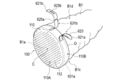
<変形例4>
図6Aは、変形例4に係る医療デバイス400の斜視図である。 <Modification example 4>
FIG. 6A is a perspective view of themedical device 400 according to the modified example 4.
図6Aは、変形例4に係る医療デバイス400の斜視図である。 <Modification example 4>
FIG. 6A is a perspective view of the
変形例4に係る医療デバイス400が備える癒合促進シート410の枠部410Bは、癒合促進シート410の周方向に配置された複数の突出部411a、411b、411cを有する。突出部411a、411b、411cの各々は、牽引部120が挿通可能な孔部412を有する。各突出部411a、411b、411cの間には所定の空間(隙間)gが形成されている。各突出部411a、411b、411cは、略三角形の平面形状を有する。
The frame portion 410B of the fusion promoting sheet 410 included in the medical device 400 according to the modified example 4 has a plurality of protruding portions 411a, 411b, and 411c arranged in the circumferential direction of the fusion promoting sheet 410. Each of the protrusions 411a, 411b, and 411c has a hole 412 through which the traction part 120 can be inserted. A predetermined space (gap) g is formed between the protruding portions 411a, 411b, and 411c. Each protrusion 411a, 411b, 411c has a substantially triangular planar shape.
術者は、牽引部120を牽引することにより、各突出部411a、411b、411cを膵実質B1の外周面に沿うように変形させることができる。また、各突出部411a、411b、411cは、膵実質B1の外周面の少なくとも一部を覆うように配置される。各突出部411a、411b、411cは、前述した枠部110B(図1Aを参照)と比較して、牽引操作された際に容易に変形する。したがって、各突出部411a、411b、411cを膵実質B1の外周面に沿わせるようにより確実に変形させることができる。
By pulling the traction portion 120, the operator can deform each protrusion 411a, 411b, 411c along the outer peripheral surface of the pancreatic parenchyma B1. Further, each protrusion 411a, 411b, 411c is arranged so as to cover at least a part of the outer peripheral surface of the pancreatic parenchyma B1. Each of the protruding portions 411a, 411b, and 411c is easily deformed when being towed, as compared with the frame portion 110B (see FIG. 1A) described above. Therefore, each protrusion 411a, 411b, 411c can be more reliably deformed along the outer peripheral surface of the pancreatic parenchyma B1.
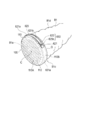
<変形例5>
図6Bは、変形例5に係る医療デバイス500の斜視図である。 <Modification 5>
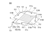
FIG. 6B is a perspective view of themedical device 500 according to the modified example 5.
図6Bは、変形例5に係る医療デバイス500の斜視図である。 <Modification 5>
FIG. 6B is a perspective view of the
変形例5に係る医療デバイス500が備える癒合促進シート510の枠部510Bは、4つの突出部511a、511b、511c、511cを有する。突出部511a、511b、511c、511dの各々は、牽引部120が挿通可能な孔部512を有する。各突出部511a、511b、511c、511dの間には所定の空間(隙間)gが形成されている。各突出部511a、511b、511cは、略長方形の平面形状を有する。変形例5に係る医療デバイス500は、変形例4に係る医療デバイス400と同様に、牽引部120が牽引された際に、各突出部511a、511b、511c、511dが容易に変形するため、膵実質B1の外周面に沿うようにより確実に変形させることができる。なお、変形例4、5で示した突出部の形状や数等は、特に限定されない。
The frame portion 510B of the fusion promoting sheet 510 included in the medical device 500 according to the modified example 5 has four protruding portions 511a, 511b, 511c, and 511c. Each of the protrusions 511a, 511b, 511c, and 511d has a hole 512 through which the traction unit 120 can be inserted. A predetermined space (gap) g is formed between the protruding portions 511a, 511b, 511c, and 511d. Each protrusion 511a, 511b, 511c has a substantially rectangular planar shape. Similar to the medical device 400 according to the modified example 4, the medical device 500 according to the modified example 5 is pancreas because the protruding portions 511a, 511b, 511c, and 511d are easily deformed when the traction portion 120 is pulled. It can be deformed more reliably along the outer peripheral surface of B1. The shape and number of the protrusions shown in the modified examples 4 and 5 are not particularly limited.
<処置方法の実施形態(生体器官吻合術)>
次に、医療デバイスを用いた処置方法を説明する。 <Example of treatment method (living organ anastomosis)>
Next, a treatment method using a medical device will be described.
次に、医療デバイスを用いた処置方法を説明する。 <Example of treatment method (living organ anastomosis)>
Next, a treatment method using a medical device will be described.
図7は、医療デバイスを用いた処置方法の各手順を示すフローチャートである。
FIG. 7 is a flowchart showing each procedure of the treatment method using the medical device.
処置方法は、牽引部が設けられた癒合促進シートを備える医療デバイスを準備すること(S11)、癒合促進シートを一方の被接合部位に配置すること(S12)、牽引部を牽引して癒合促進シートを変形させること(S13)、癒合促進シートを一方の被接合部位に固定すること(S14)、一方の被接合部位と他方の被接合部位との間に癒合促進シートの少なくとも一部を配置した状態で一方の被接合部位と他方の被接合部位とを接合すること(S15)、を含む。
The treatment method is to prepare a medical device provided with a fusion promoting sheet provided with a traction portion (S11), arrange the fusion promotion sheet at one of the joined sites (S12), and pull the traction portion to promote fusion. Deform the sheet (S13), fix the fusion-promoting sheet to one bonded site (S14), and place at least a part of the fusion-promoting sheet between one bonded site and the other bonded site. This includes joining one of the parts to be joined and the other part to be joined (S15) in this state.
処置方法により接合される生体器官および生体器官における被接合部位は特に限定されず、任意に選択することができる。以下の説明では、膵実質-空腸吻合術を例に挙げて説明する。ただし、上記処置方法は、大腸吻合術や胃管吻合術に適用されてもよい。また、以下に説明する各手技において使用される医療デバイスとしては、例えば、前述した医療デバイスの中から任意のものを選択することが可能である。ただし、以下の説明では、各手技に好適に用いることができる代表的な例として、特定の医療デバイスの使用例を説明する。また、以下に説明する各手技において、公知の手技手順や公知の医療装置・医療器具等については詳細な説明を適宜省略する。
The living organ to be joined by the treatment method and the joining site in the living organ are not particularly limited and can be arbitrarily selected. In the following description, pancreatic parenchymal-jejunal anastomosis will be described as an example. However, the above-mentioned treatment method may be applied to colon anastomosis or gastric tube anastomosis. Further, as the medical device used in each of the procedures described below, for example, any of the above-mentioned medical devices can be selected. However, in the following description, a usage example of a specific medical device will be described as a typical example that can be suitably used for each procedure. In addition, in each procedure described below, detailed description of known procedure procedures, known medical devices, medical instruments, etc. will be omitted as appropriate.
以下、本明細書の説明において「生体器官の間に癒合促進シートを配置する」とは、生体器官に癒合促進シートが直接的にまたは間接的に接触した状態で配置されること、生体器官との間に空間的な隙間が形成された状態で癒合促進シートが配置されること、またはその両方の状態で癒合促進シートが配置されること(例えば、一方の生体器官に癒合促進シートが接触し、他方の生体器官には癒合促進シートが接触していない状態で配置されること)の少なくとも一つを意味する。また、本明細書の説明において「周辺」とは、厳密な範囲(領域)を規定するものではなく、処置の目的(生体器官同士の接合)を達成し得る限りにおいて、所定の範囲(領域)を意味する。また、各処置方法において説明する手技手順は、処置の目的を達成し得る限りにおいて、順番を適宜入れ替えることが可能である。
Hereinafter, in the description of the present specification, "arranging the fusion promoting sheet between the living organs" means that the fusion promoting sheet is arranged in a state of being in direct or indirect contact with the living organ, and the living organ The fusion-promoting sheet is placed with a spatial gap formed between the two, or the fusion-promoting sheet is placed in both states (for example, the fusion-promoting sheet comes into contact with one of the biological organs). , The fusion promoting sheet is placed in contact with the other living organ). Further, in the description of the present specification, the term "periphery" does not define a strict range (region), but a predetermined range (region) as long as the purpose of treatment (bonding between biological organs) can be achieved. Means. In addition, the order of the procedure procedures described in each treatment method can be changed as appropriate as long as the purpose of the treatment can be achieved.
<処置方法の実施形態(膵実質-空腸吻合術)>
図8は、処置方法の実施形態(膵実質-空腸吻合術)の手順を示すフローチャートであり、図9~図16は、膵実質-空腸吻合術の説明に供する図である。 <Example of treatment method (pancreatic parenchyma-jejunal anastomosis)>
FIG. 8 is a flowchart showing the procedure of the embodiment of the treatment method (pancreatic parenchymal-jejunal anastomosis), and FIGS. 9 to 16 are views provided for explaining the pancreatic parenchymal-jejunal anastomosis.
本実施形態に係る処置方法において、接合対象となる生体器官は、膵頭十二指腸切除後の膵実質B1と、空腸B2である。以下の説明では、切断した膵実質B1の切断面B1a周辺(一方の被接合部位)と空腸B2の腸壁の任意の部位(他方の被接合部位)を接合する手順を説明する。また、本実施形態では、図1Aに示した医療デバイス100の使用例を説明する。
In the treatment method according to the present embodiment, the biological organs to be joined are the pancreatic parenchyma B1 after pancreaticoduodenectomy and the jejunum B2. In the following description, a procedure for joining the periphery of the cut surface B1a of the cut pancreatic parenchyma B1 (one joined site) and an arbitrary site of the intestinal wall of the jejunum B2 (the other joined site) will be described. Further, in the present embodiment, an example of using the medical device 100 shown in FIG. 1A will be described.
図8に示すように、本実施形態に係る処置方法は、牽引部120が設けられた癒合促進シート110を備える医療デバイス100を準備すること(S101)、癒合促進シート110を膵実質B1の切断面B1a上に配置すること(S102)、牽引部120を牽引して癒合促進シート110を変形させること(S103)、癒合促進シートを固定部材で固定すること(S104)、膵実質B1と空腸B2の間に癒合促進シート110を挟み込むこと(S105)、膵実質B1と空腸B2の間に癒合促進シート110を挟み込んだ状態で接合すること(S106)、膵実質B1と空腸B2の間に癒合促進シート110を留置すること(S107)、を含む。
As shown in FIG. 8, the treatment method according to the present embodiment is to prepare a medical device 100 including a fusion promoting sheet 110 provided with a traction portion 120 (S101), and to cut the fusion promoting sheet 110 into the pancreatic parenchyma B1. Placing it on the surface B1a (S102), pulling the traction unit 120 to deform the fusion promoting sheet 110 (S103), fixing the fusion promoting sheet with a fixing member (S104), pancreatic parenchyma B1 and jejunum B2. The fusion promoting sheet 110 is sandwiched between the pancreatic parenchyma B1 and the jejunum B2 (S105), the fusion promoting sheet 110 is sandwiched between the pancreatic parenchyma B1 and the jejunum B2 (S106), and the fusion promoting is promoted between the pancreatic parenchyma B1 and the jejunum B2. Indwelling the sheet 110 (S107).
次に、図9~図16を参照して、本実施形態に係る処置方法の一例を具体的に説明する。なお、図14では、後述する複数の両端針920a~920eを省略している。
Next, an example of the treatment method according to the present embodiment will be specifically described with reference to FIGS. 9 to 16. In FIG. 14, a plurality of needles at both ends 920a to 920e, which will be described later, are omitted.
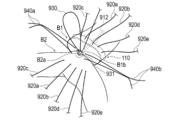
図9に示すように、術者は、癒合促進シート110の裏面114(又は表面113)を膵実質B1の切断面B1aに対向させる。術者は、面方向において、接続部123が、切断面B1aよりも外方側になるように配置する。術者は、牽引部120を牽引することにより、枠部110Bが膵実質B1の外周面の一部を覆うよう癒合促進シート110を変形させることができる。このような作業を行うことにより、術者は、癒合促進部110Aを膵実質B1の切断面B1aに密着させた状態で保持することができる(図1Bを参照)。
As shown in FIG. 9, the operator makes the back surface 114 (or surface 113) of the fusion promoting sheet 110 face the cut surface B1a of the pancreatic parenchyma B1. The surgeon arranges the connecting portion 123 so as to be on the outer side of the cut surface B1a in the surface direction. By pulling the traction portion 120, the operator can deform the fusion promoting sheet 110 so that the frame portion 110B covers a part of the outer peripheral surface of the pancreatic parenchyma B1. By performing such an operation, the operator can hold the fusion promoting portion 110A in close contact with the cut surface B1a of the pancreatic parenchyma B1 (see FIG. 1B).
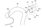
癒合促進シート110を膵実質B1の切断面B1aに配置する際、術者は、以下の作業手順を採用することができる。まず、術者は、膵管チューブ910の端部911(または端部912)を癒合促進シート110に押し付けることによって癒合促進シート110に孔部130を形成する。また、術者は、膵管チューブ910の端部911が空腸B2の吻合予定部位の貫通孔B2aから空腸B2の内部を通り、空腸B2の貫通孔B2bから空腸B2の外部に出るように、膵管チューブ910を空腸B2に挿通させる。
When arranging the fusion promotion sheet 110 on the cut surface B1a of the pancreatic parenchyma B1, the operator can adopt the following work procedure. First, the operator forms a hole 130 in the fusion promoting sheet 110 by pressing the end 911 (or end 912) of the pancreatic duct tube 910 against the fusion promoting sheet 110. In addition, the operator performed the pancreatic duct tube so that the end 911 of the pancreatic duct tube 910 passes through the inside of the jejunum B2 through the through hole B2a of the planned anastomosis site of the jejunum B2 and exits from the through hole B2b of the jejunum B2 to the outside of the jejunum B2. 910 is inserted into jejunum B2.
次に、術者は、膵管チューブ910が癒合促進シート110の孔部130を挿通して癒合促進シート110を保持した状態で、膵管チューブ910の端部912を膵実質B1の膵管B1bに仮挿入する。
Next, the operator temporarily inserts the end portion 912 of the pancreatic duct tube 910 into the pancreatic duct B1b of the pancreatic parenchyma B1 while the pancreatic duct tube 910 inserts the hole 130 of the fusion promoting sheet 110 and holds the fusion promoting sheet 110. To do.
なお、膵管チューブ910としては、例えば、端部912に抜け防止用のコブ(凸部)が形成された樹脂製の公知のものを利用することができる。膵管B1bに仮挿入された膵管チューブ910は、手技中に膵管B1bから膵液等の体液が漏出することを抑制する。このような手順によれば、術者は、癒合促進シート110の配置及び膵管チューブ910の仮挿入を一度に行うことができる。
As the pancreatic duct tube 910, for example, a known resin tube having a bump (convex portion) formed at the end portion 912 to prevent removal can be used. The pancreatic duct tube 910 temporarily inserted into the pancreatic duct B1b suppresses the leakage of body fluid such as pancreatic juice from the pancreatic duct B1b during the procedure. According to such a procedure, the operator can arrange the fusion promoting sheet 110 and temporarily insert the pancreatic duct tube 910 at the same time.
また、術者は、膵管チューブ910を挿通させるための孔部130を形成する際に、膵管チューブ910ではなく他のデバイスを用いてもよい。また、膵管チューブ910を挿通させるための孔部130は、使用前の状態で予め癒合促進シート110に形成されていてもよい。また、術者は、膵実質B1の切断面B1aに癒合促進シート110を配置した後に、膵管チューブ910を膵管B1bに仮挿入してもよい。
Further, the operator may use a device other than the pancreatic duct tube 910 when forming the hole 130 for inserting the pancreatic duct tube 910. Further, the hole 130 through which the pancreatic duct tube 910 is inserted may be formed in the fusion promoting sheet 110 in advance in a state before use. Further, the operator may temporarily insert the pancreatic duct tube 910 into the pancreatic duct B1b after arranging the fusion promoting sheet 110 on the cut surface B1a of the pancreatic parenchyma B1.
次に、術者は、癒合促進シート110を固定部材で膵実質B1に固定する。なお、以下の説明では、縫合糸付きの複数の両端針920a~920eを固定部材として用いて癒合促進シート110を膵実質B1に固定する手順の一例を説明する。両端針920a~920eとしては、生体吸収性を備える吸収糸(縫合糸)と、吸収糸の両端に取り付けられた生体適合性を備える針部と、を有する公知のものを用いることができる。なお、後述する両端針930、940a~940eについても、吸収糸および針部を備えるように構成している。
Next, the operator fixes the fusion promoting sheet 110 to the pancreatic parenchyma B1 with a fixing member. In the following description, an example of a procedure for fixing the fusion promoting sheet 110 to the pancreatic parenchyma B1 by using a plurality of both end needles 920a to 920e with sutures as fixing members will be described. As the needles at both ends 920a to 920e, known needles having a bioabsorbable absorbent thread (suture) and a biocompatible needle portion attached to both ends of the absorbent thread can be used. The needles 930 and 940a to 940e at both ends, which will be described later, are also configured to include an absorbent thread and a needle portion.
まず、術者は、図10に示すように、膵実質B1に対して癒合促進シート110を保持した状態で、膵実質B1の後壁B1c(膵実質B1の周方向の背側の部分)および癒合促進シート110において後壁B1c上に配置された部分から、膵実質B1の前壁B1dおよび癒合促進シート110において前壁B1d上に配置された部分に向かって、両端針920aを運針する。次に、術者は、空腸B2の吻合予定部位(貫通孔B2aの周辺)の空腸漿膜筋層を挿通するように両端針920aを運針する。術者は、このような操作を繰り返し、図11に示すように、癒合促進シート110、膵実質B1、および空腸B2の空腸漿膜筋層に複数の両端針920a~920eに複数の両端針920a~920eを挿通させる。このように、術者は、膵実質B1と空腸B2を縫合する複数の両端針920a~920eを利用して、癒合促進シート110を膵実質B1に固定できる。
First, as shown in FIG. 10, the operator holds the fusion promoting sheet 110 against the pancreatic parenchyma B1 and holds the posterior wall B1c of the pancreatic parenchyma B1 (the dorsal portion of the pancreatic parenchyma B1 in the circumferential direction) and Both ends needles 920a are moved from the portion of the fusion promoting sheet 110 arranged on the posterior wall B1c toward the anterior wall B1d of the pancreatic parenchyma B1 and the portion of the fusion promoting sheet 110 arranged on the anterior wall B1d. Next, the operator moves both ends of the needle 920a so as to insert the jejunal serosal muscular layer at the planned anastomosis site of the jejunum B2 (around the through hole B2a). The operator repeats such an operation, and as shown in FIG. 11, a plurality of both ends needles 920a to 920e on the jejunal serosal muscular layer of the fusion promoting sheet 110, the pancreatic parenchyma B1, and the jejunum B2, and a plurality of both ends needles 920a to The 920e is inserted. In this way, the operator can fix the fusion promoting sheet 110 to the pancreatic parenchyma B1 by using a plurality of both end needles 920a to 920e that suture the pancreatic parenchyma B1 and the jejunum B2.
術者は、癒合促進シート110を膵実質B1の切断面B1aに固定した後、牽引部120を癒合促進シート110から適宜分離させてもよい。術者は、癒合促進シート110を膵実質B1の切断面B1aに固定するまでの間、牽引部120を牽引して、癒合促進シート110の枠部110Bを膵実質B1の外周面に密着させた状態を維持することにより、癒合促進シート110が膵実質B1からズレたり、脱落したりすることを防止することができる。
The surgeon may appropriately separate the traction portion 120 from the fusion promoting sheet 110 after fixing the fusion promoting sheet 110 to the cut surface B1a of the pancreatic parenchyma B1. The operator pulled the traction portion 120 until the fusion promoting sheet 110 was fixed to the cut surface B1a of the pancreatic parenchyma B1 so that the frame portion 110B of the fusion promoting sheet 110 was brought into close contact with the outer peripheral surface of the pancreatic parenchyma B1. By maintaining the state, it is possible to prevent the fusion promoting sheet 110 from being displaced or dropped from the pancreatic parenchyma B1.
なお、膵実質B1および空腸B2の空腸漿膜筋層に挿通させる両端針の本数や両端針を挿通させる位置は特に限定されない。また、術者は、複数の両端針920a~920eではなく、生分解性のステープル等を固定部材として、癒合促進シート110を膵実質B1に固定してもよい。
The number of both-end needles to be inserted into the jejunal serosal muscular layer of the pancreatic parenchyma B1 and the jejunum B2 and the position to insert the both-end needles are not particularly limited. Further, the operator may fix the fusion promoting sheet 110 to the pancreatic parenchyma B1 by using biodegradable staples or the like as a fixing member instead of the plurality of needles 920a to 920e at both ends.
次に、術者は、図11に示すように、膵管チューブ910の端部912を膵管B1bから抜去する。
Next, the operator removes the end 912 of the pancreatic duct tube 910 from the pancreatic duct B1b, as shown in FIG.
次に、術者は、図11に示すように、膵管B1bの内腔側から膵実質B1の切断面B1aの前壁B1d側の部分に向かって、両端針930を通す。両端針930は、空腸B2を挿通させない状態でピンセット等の把持器具(図示省略)で手技の邪魔にならないように保持される。
Next, as shown in FIG. 11, the operator passes the needles 930 at both ends from the lumen side of the pancreatic duct B1b toward the front wall B1d side of the cut surface B1a of the pancreatic parenchyma B1. The needles 930 at both ends are held by a gripping instrument such as tweezers (not shown) so as not to interfere with the procedure in a state where the jejunum B2 is not inserted.
次に、術者は、図11および図13に示すように、膵管B1bの内腔側から膵実質B1の切断面B1aに向かって、両端針940aの一端を運針する。次に、術者は、図12および図13に示すように、両端針940aの他端を空腸B2の貫通孔B2aに挿入し、空腸B2の内部から空腸B2の外部に向かって両端針940aの他端を運針する。そして、術者は、図14に示すように、膵管B1bの周方向の異なる部位および空腸B2に、複数の両端針940a~940eを挿通させる。なお、図13は、吻合される前の膵実質B1と空腸B2の一部をも模式的に示す断面図である。
Next, as shown in FIGS. 11 and 13, the operator moves one end of the needles 940a at both ends from the lumen side of the pancreatic duct B1b toward the cut surface B1a of the pancreatic parenchyma B1. Next, as shown in FIGS. 12 and 13, the operator inserts the other end of the needles 940a at both ends into the through hole B2a of the jejunum B2, and the needles 940a at both ends toward the outside of the jejunum B2 from the inside of the jejunum B2. Move the other end. Then, as shown in FIG. 14, the operator inserts a plurality of both-end needles 940a to 940e into different sites in the circumferential direction of the pancreatic duct B1b and the jejunum B2. FIG. 13 is a cross-sectional view schematically showing a part of the pancreatic parenchyma B1 and the jejunum B2 before being anastomosed.
次に、術者は、図14に示すように、膵実質B1の後壁B1cおよび膵管B1bを空腸B2の吻合予定部位に密着させる。そして、複数の両端針940a~940eのうち、膵管B1bの周方向の背側(後壁B1c側)を挿通する両端針940c~940eを結紮する。
Next, as shown in FIG. 14, the operator brings the posterior wall B1c of the pancreatic parenchyma B1 and the pancreatic duct B1b into close contact with the planned anastomosis site of the jejunum B2. Then, of the plurality of needles 940a to 940e at both ends, the needles 940c to 940e at both ends that insert the dorsal side (rear wall B1c side) of the pancreatic duct B1b in the circumferential direction are ligated.
次に、術者は、図15に示すように、膵管チューブ910の端部912を膵管B1bに再挿入する。次に、術者は、両端針930において膵管B1bの内側から延びる針部931を、空腸B2に形成した貫通孔B2bに挿入し、空腸B2の内部から空腸B2の外部に向かって針部931運針する。
Next, the operator reinserts the end 912 of the pancreatic duct tube 910 into the pancreatic duct B1b, as shown in FIG. Next, the operator inserts the needle portion 931 extending from the inside of the pancreatic duct B1b in the needles 930 at both ends into the through hole B2b formed in the jejunum B2, and moves the needle portion 931 from the inside of the jejunum B2 toward the outside of the jejunum B2. To do.
次に、術者は、両端針930、940a、940bを結紮する(図示省略)。なお、膵管B1bおよび空腸B2に挿通させる両端針の本数や両端針を挿通させる位置は特に限定されない。
Next, the operator ligates the needles 930, 940a, and 940b at both ends (not shown). The number of both-end needles to be inserted into the pancreatic duct B1b and the jejunum B2 and the position to insert the both-end needles are not particularly limited.
次に、術者は、図16に示すように、術者の指を以って空腸B2を膵実質B1に対して押さえつけながら両端針920a~920eを結紮する。これによって、膵実質B1と空腸B2が癒合促進シート110を挟み込んだ状態で縫合される。空腸B2は、縫合時に生じる張力により、膵実質B1の切断面B1aおよび癒合促進シート110の癒合促進部110Aを包み込むように変形する。
Next, as shown in FIG. 16, the operator ligates the needles 920a to 920e at both ends while pressing the jejunum B2 against the pancreatic parenchyma B1 with the operator's finger. As a result, the pancreatic parenchyma B1 and the jejunum B2 are sutured with the fusion promoting sheet 110 sandwiched between them. The jejunum B2 is deformed by the tension generated at the time of suturing so as to enclose the cut surface B1a of the pancreatic parenchyma B1 and the fusion promoting portion 110A of the fusion promoting sheet 110.
術者は、膵実質B1の切断面B1aと空腸B2の腸壁との間に癒合促進シート110の癒合促進部110Aが挟み込まれた状態で癒合促進シート110を留置する。癒合促進シート110の癒合促進部110Aは、膵実質B1の切断面B1aと空腸B2の腸壁とに接触しつつ、膵実質B1の切断面B1aと空腸B2の腸壁との間に留置されることにより、膵実質B1の生体組織と空腸B2の腸壁の生体組織の癒合を促進する。
The operator places the fusion promoting sheet 110 in a state where the fusion promoting portion 110A of the fusion promoting sheet 110 is sandwiched between the cut surface B1a of the pancreatic parenchyma B1 and the intestinal wall of the jejunum B2. The fusion promoting portion 110A of the fusion promoting sheet 110 is placed between the cut surface B1a of the pancreatic parenchyma B1 and the intestinal wall of the jejunum B2 while being in contact with the cut surface B1a of the pancreatic parenchyma B1 and the intestinal wall of the jejunum B2. This promotes the fusion of the biological tissue of the pancreatic parenchyma B1 and the biological tissue of the intestinal wall of the jejunum B2.
以上のように、本実施形態に係る処置方法は、膵実質B1および空腸B2を接合する手技に適用される。また、上記の処置方法では、切断された膵実質B1の切断面B1a周辺と空腸B2の腸壁(空腸漿膜筋層)を接合する。この処置方法によれば、膵実質B1の切断面B1aと空腸B2の腸壁の間に挟み込んだ癒合促進シート110の癒合促進部110Aにより、膵実質B1の生体組織と空腸B2の腸壁の生体組織の癒合を促進することができ、膵実質-空腸吻合術後の縫合不全のリスクを低減させることができる。
As described above, the treatment method according to the present embodiment is applied to the procedure for joining the pancreatic parenchyma B1 and the jejunum B2. Further, in the above treatment method, the periphery of the cut surface B1a of the cut pancreatic parenchyma B1 and the intestinal wall (jejunal serosal muscular layer) of the jejunum B2 are joined. According to this treatment method, the biological tissue of the pancreatic parenchyma B1 and the living body of the intestinal wall of the jejunum B2 are formed by the fusion promoting portion 110A of the fusion promoting sheet 110 sandwiched between the cut surface B1a of the pancreatic parenchyma B1 and the intestinal wall of the jejunum B2. Tissue fusion can be promoted and the risk of suture failure after pancreatic parenchymal-jejunostomy can be reduced.
また、術者は、牽引部120により癒合促進シート110の枠部110Bが膵実質B1の外周面の少なくとも一部を覆うように変形させることで、癒合促進シート110にヨレやズレが発生することを好適に防止することができる。
Further, the surgeon deforms the frame portion 110B of the fusion promoting sheet 110 so as to cover at least a part of the outer peripheral surface of the pancreatic parenchyma B1 by the traction portion 120, so that the fusion promoting sheet 110 is twisted or displaced. Can be suitably prevented.
<他の変形例>
次に、図17~図22を参照して、他の変形例に係る牽引部620を説明する。本変形例の説明では、上述した実施形態で既に説明した内容と重複する内容の説明は省略する。また、変形例の説明において特に説明の無い内容は前述した実施形態と同一のものとすることができる。 <Other variants>
Next, thetraction unit 620 according to another modified example will be described with reference to FIGS. 17 to 22. In the description of this modification, the description of the content that overlaps with the content already described in the above-described embodiment will be omitted. In addition, the contents not particularly explained in the description of the modified example can be the same as those in the above-described embodiment.
次に、図17~図22を参照して、他の変形例に係る牽引部620を説明する。本変形例の説明では、上述した実施形態で既に説明した内容と重複する内容の説明は省略する。また、変形例の説明において特に説明の無い内容は前述した実施形態と同一のものとすることができる。 <Other variants>
Next, the
図17は、癒合促進シート110に接続する前の状態における牽引部620の平面図を示す。図18~図22は、牽引部620を備える医療デバイス100を使用した手技の手順例を示す。
FIG. 17 shows a plan view of the traction portion 620 in a state before being connected to the fusion promotion sheet 110. 18 to 22 show a procedure example of the procedure using the medical device 100 including the traction unit 620.
図17に示すように、牽引部620は、所定の幅及び長さを備える帯状の本体部621と、本体部621の長手方向の一端部621a側に形成された複数のスリット部623と、本体部621の長手方向の他端部621b側に形成された第1孔部625a及び第2孔部625bと、を有する。
As shown in FIG. 17, the traction portion 620 includes a strip-shaped main body portion 621 having a predetermined width and length, a plurality of slit portions 623 formed on one end portion 621a side in the longitudinal direction of the main body portion 621, and a main body. It has a first hole portion 625a and a second hole portion 625b formed on the other end portion 621b side in the longitudinal direction of the portion 621.
本体部621の一端部621aは、例えば、一端部621aの先端側に向けて先細るテーパー形状に形成することができる。このような形状を設けることにより、本体部621の一端部621aを各孔部625a、625bに通す作業を簡単に行うことができる(図19、図20を参照)。
One end portion 621a of the main body portion 621 can be formed, for example, into a tapered shape that tapers toward the tip end side of the one end portion 621a. By providing such a shape, it is possible to easily pass the one end portion 621a of the main body portion 621 through the holes 625a and 625b (see FIGS. 19 and 20).
第1孔部625aは、第2孔部625bよりも本体部621の一端部621a側に配置している。第1孔部625aと第2孔部625bは互いに直交する方向に延びている。第1孔部625aは、本体部621の幅方向(図17の左右方向)に略平行に延びている。第2孔部625bは、本体部621の長手方向(図17の上下方向)に略平行に延びている。
The first hole portion 625a is arranged closer to one end portion 621a of the main body portion 621 than the second hole portion 625b. The first hole portion 625a and the second hole portion 625b extend in directions orthogonal to each other. The first hole portion 625a extends substantially parallel to the width direction (horizontal direction in FIG. 17) of the main body portion 621. The second hole portion 625b extends substantially parallel to the longitudinal direction (vertical direction in FIG. 17) of the main body portion 621.
第1孔部625aは、例えば、図17に示す平面視において本体部621の幅方向に沿って長辺が配置される略長方形の形状で形成することができる。第2孔部625bは、例えば、図17に示す平面視において本体部621の長手方向に沿って長辺が配置される略長方形の形状で形成することができる。なお、各孔部625a、625bの形状、位置、大きさ等は、特に限定されない。
The first hole portion 625a can be formed, for example, in a substantially rectangular shape in which long sides are arranged along the width direction of the main body portion 621 in the plan view shown in FIG. The second hole portion 625b can be formed, for example, in a substantially rectangular shape in which long sides are arranged along the longitudinal direction of the main body portion 621 in the plan view shown in FIG. The shape, position, size, etc. of the holes 625a and 625b are not particularly limited.
スリット部623は、本体部621の長手方向と平行な方向に対して傾斜して延びている。具体的には、スリット部623は、本体部621の中心側から外方側へ向けて傾斜している。なお、スリット部623の個数や形状、本体部621に設ける具体的な位置等は特に限定されない。
The slit portion 623 is inclined and extends in a direction parallel to the longitudinal direction of the main body portion 621. Specifically, the slit portion 623 is inclined from the center side of the main body portion 621 toward the outside. The number and shape of the slit portions 623, the specific position provided in the main body portion 621, and the like are not particularly limited.
本体部621の一部は、図18に示すように、癒合促進シート110の枠部(第2領域)110Bに接続される接続部631aを構成する。接続部631aは、前述した実施形態で説明した接続部121(図1Bを参照)と同様に、例えば、枠部110Bに対して摺動可能に接続することができる。また、図18に示すように、本体部621の一部は、癒合促進シート110の枠部110Bとは接続されない非接続部631bを構成する。
As shown in FIG. 18, a part of the main body portion 621 constitutes a connecting portion 631a connected to the frame portion (second region) 110B of the fusion promoting sheet 110. The connecting portion 631a can be slidably connected to, for example, the frame portion 110B in the same manner as the connecting portion 121 (see FIG. 1B) described in the above-described embodiment. Further, as shown in FIG. 18, a part of the main body portion 621 constitutes a non-connecting portion 631b that is not connected to the frame portion 110B of the fusion promoting sheet 110.
図22に示すように、非接続部631bに配置されたスリット部623及び各孔部625a、625bは、癒合促進シート110の枠部110Bの変形量を調整可能にする調整部650としての機能を有する。
As shown in FIG. 22, the slit portion 623 and the holes 625a and 625b arranged in the non-connecting portion 631b function as an adjusting portion 650 that makes it possible to adjust the amount of deformation of the frame portion 110B of the fusion promoting sheet 110. Have.
次に、図18~図22を参照して、牽引部620を備える医療デバイス100を使用した手技の手順例を示す。なお、前述した実施形態で既に説明した手順等については適宜省略する。
Next, with reference to FIGS. 18 to 22, an example of the procedure of the procedure using the medical device 100 provided with the traction unit 620 will be shown. The procedure and the like already described in the above-described embodiment will be omitted as appropriate.
術者は、図18に示すように、膵実質B1の切断面B1aに癒合促進シート110の癒合促進部110Aを配置する。術者は、牽引部620の非接続部631bに位置する両端部621b、621bを牽引することにより、癒合促進シート110を変形させて、癒合促進シート110の枠部110Bで膵実質B1の外周面の一部を覆わせる。
As shown in FIG. 18, the operator arranges the fusion promoting portion 110A of the fusion promoting sheet 110 on the cut surface B1a of the pancreatic parenchyma B1. The operator deforms the fusion promoting sheet 110 by pulling both end portions 621b and 621b located at the non-connecting portion 631b of the traction portion 620, and the outer peripheral surface of the pancreatic parenchyma B1 at the frame portion 110B of the fusion promoting sheet 110. Cover a part of.
術者は、図19、図20に示すように、各孔部625a、625bに本体部621の一端部621a側の一部を挿通させる。術者は、各孔部625a、625bに本体部621の一端部621a側の一部を挿通させる際、本体部621の他端部621b側の一部を折り返すように変形させる。術者は、このような作業を行う際、例えば、鉗子などの医療器具710を使用することができる。具体的には、術者は、図19に示すように、各孔部625a、625bに通した医療器具710で本体部621の一端部621a側の一部を把持しつつ、図20に示すように、医療器具710を持ち上げるように操作する。術者は、このような操作を行うことにより、医療器具710とともに本体部621の一端部621a側の一部を各孔部625a、625bに簡単に通すことができる。
As shown in FIGS. 19 and 20, the surgeon inserts a part of the main body portion 621 on the one end portion 621a side into the holes 625a and 625b. When the surgeon inserts a part of the main body 621 on the one end 621a side into each of the holes 625a and 625b, the operator deforms a part of the main body 621 on the other end 621b side so as to be folded back. The surgeon can use, for example, a medical instrument 710 such as forceps when performing such an operation. Specifically, as shown in FIG. 19, the surgeon grasps a part of the main body 621 on the one end 621a side with the medical instrument 710 passed through the holes 625a and 625b, as shown in FIG. The medical instrument 710 is operated to be lifted. By performing such an operation, the operator can easily pass a part of the main body 621 on the one end 621a side together with the medical instrument 710 through the holes 625a and 625b.
術者は、図21に示すように、鉗子などの医療器具720を使用して本体部621において各孔部625a、625bが配置された部分やその周辺部を押さえつつ、本体部621において各孔部625a、625bに挿通させた部分を牽引することにより、膵実質B1に対して癒合促進シート110を保持することができる。
As shown in FIG. 21, the surgeon uses a medical instrument 720 such as forceps to hold each hole in the main body 621 while holding the portion where the holes 625a and 625b are arranged and the peripheral portion thereof. By pulling the portions inserted through the portions 625a and 625b, the fusion promoting sheet 110 can be held with respect to the pancreatic parenchyma B1.
術者が牽引部620の牽引を解除した状態においても、スリット部623が第1孔部625a及び第2孔部625bに引っ掛かった状態を維持する。そのため、膵実質B1に対して癒合促進シート110を保持する保持力を好適に維持することができる。
Even when the operator releases the traction of the traction portion 620, the slit portion 623 is maintained in a state of being caught by the first hole portion 625a and the second hole portion 625b. Therefore, the holding power for holding the fusion promoting sheet 110 with respect to the pancreatic parenchyma B1 can be suitably maintained.
本変形例では、第2孔部625bよりも膵実質B1に近接した位置(膵実質B1の外周面に近接した位置)に配置される第1孔部625aは、牽引部620の幅方向に沿って延びている(図17を参照)。また、図19、図22に示すように、第1孔部625aは、膵実質Baの延在方向に沿って配置される。したがって、術者は、牽引部620の本体部621において第1孔部625aに挿通された部分の幅が過剰に小さくなるように変形することを防止できる。したがって、牽引部620の本体部621において第1孔部625aに挿通された部分が膵実質Baに与える負荷を小さく抑えることができる。一方で、第1孔部625aよりも膵実質B1から離間した位置(膵実質B1の外周面から離間した位置)に配置される第2孔部625bは、牽引部620の幅方向と交差する方向に沿って延びている(図17を参照)。そのため、牽引部620の本体部621において第2孔部625bに挿通された部分は、小さな幅を備える第2孔部625bの形状に沿って幅が小さくなるように変形する。小さな幅を備える第2孔部625bに、第2孔部625bよりも大きな幅を備える本体部621が挿通されることにより、第2孔部625bの内周部と本体部621との間の引っ掛かりが強くなる。そのため、膵実質B1に対する癒合促進シート110の保持力を効果的に高めることができる。
In this modification, the first hole portion 625a arranged at a position closer to the pancreatic parenchyma B1 than the second hole portion 625b (a position closer to the outer peripheral surface of the pancreatic parenchyma B1) is along the width direction of the traction portion 620. (See FIG. 17). Further, as shown in FIGS. 19 and 22, the first hole portion 625a is arranged along the extending direction of the pancreatic parenchyma Ba. Therefore, the operator can prevent the main body portion 621 of the traction portion 620 from being deformed so that the width of the portion inserted through the first hole portion 625a becomes excessively small. Therefore, in the main body portion 621 of the traction portion 620, the load applied to the pancreatic parenchyma Ba by the portion inserted through the first hole portion 625a can be suppressed to a small value. On the other hand, the second hole portion 625b arranged at a position separated from the pancreatic parenchyma B1 from the first hole portion 625a (a position separated from the outer peripheral surface of the pancreatic parenchyma B1) is in a direction intersecting the width direction of the traction portion 620. Extends along (see FIG. 17). Therefore, the portion of the main body portion 621 of the traction portion 620 that is inserted through the second hole portion 625b is deformed so that the width becomes smaller along the shape of the second hole portion 625b having a small width. By inserting the main body portion 621 having a width larger than that of the second hole portion 625b into the second hole portion 625b having a small width, it is caught between the inner peripheral portion of the second hole portion 625b and the main body portion 621. Becomes stronger. Therefore, the holding power of the fusion promoting sheet 110 with respect to the pancreatic parenchyma B1 can be effectively increased.
術者は、図22に示すように、本体部625において第1孔部625a及び第2孔部625bに挿通させた一端部621a側を膵実質Baに巻き付けることができる。なお、本体部625の上記部分は切除してもよい。
As shown in FIG. 22, the operator can wrap the one end portion 621a side inserted through the first hole portion 625a and the second hole portion 625b in the main body portion 625 around the pancreatic parenchyma Ba. The above portion of the main body portion 625 may be excised.
以上のように、本変形例に係る牽引部620を備える医療デバイス100によれば、膵実質Baに与える負荷を軽減しつつ、膵実質Baに対する癒合促進シート110の保持力を効果的に高めることができる。
As described above, according to the medical device 100 provided with the traction portion 620 according to the present modification, the holding force of the fusion promoting sheet 110 on the pancreatic parenchymal Ba is effectively increased while reducing the load applied to the pancreatic parenchymal Ba. Can be done.
本出願は、2019年3月28日に出願された日本国特許出願第2019-65048号に基づいており、その開示内容は、参照により全体として引用されている。
This application is based on Japanese Patent Application No. 2019-65048 filed on March 28, 2019, and the disclosure contents are cited as a whole by reference.
100、200、400、500 医療デバイス、
110、410、510 癒合促進シート、
110A 癒合促進部(第1領域)、
110B、410B、510B 枠部(第2領域)、
112 貫通孔、
120、120A、120B、120C、220、220A、220B、220C、220D、220E、320 牽引部、
121、221、321 接続部、
123、223 非接続部、
150 調整部、
180 保持部材、
411a、411b、411c、511a、511b、511c、511d 突出部、
B1 膵実質、
B2 空腸。 100, 200, 400, 500 medical devices,
110, 410, 510 fusion promotion sheet,
110A Healing Promotion Department (1st area),
110B, 410B, 510B frame (second area),
112 through hole,
120, 120A, 120B, 120C, 220, 220A, 220B, 220C, 220D, 220E, 320 traction section,
121, 221 and 321 connections,
123, 223 non-connection part,
150 adjustment part,
180 holding member,
411a, 411b, 411c, 511a, 511b, 511c, 511d
B1 pancreatic parenchyma,
B2 jejunum.
Claims (7)
- 生体組織の癒合を促進する第1領域と、前記第1領域よりも面方向の外方側に設けられた第2領域と、を備える癒合促進シートと、
前記癒合促進シートに接続され、牽引操作に伴って接合対象となる生体器官の外周面の少なくとも一部を覆うように前記第2領域を変形させる牽引部と、を有する医療デバイス。 A fusion promoting sheet comprising a first region for promoting fusion of living tissues and a second region provided on the outer side in the plane direction from the first region.
A medical device having a traction portion connected to the fusion promoting sheet and deforming the second region so as to cover at least a part of an outer peripheral surface of a biological organ to be joined with a traction operation. - 前記牽引部は、前記第2領域に接続された接続部と、前記第2領域とは接続されておらず、かつ、前記癒合促進シートの外方側へ引き出された非接続部と、を有する請求項1に記載の医療デバイス。 The traction portion has a connecting portion connected to the second region and a non-connecting portion that is not connected to the second region and is pulled out to the outer side of the fusion promoting sheet. The medical device according to claim 1.
- 前記接続部は、前記癒合促進シートの周方向に沿う半分以上の長さで前記第2領域と接続されている、請求項2に記載の医療デバイス。 The medical device according to claim 2, wherein the connecting portion is connected to the second region with a length of half or more along the circumferential direction of the fusion promoting sheet.
- 前記接続部の少なくとも一部は、前記非接続部よりも大きな剛性を備える、請求項2または請求項3に記載の医療デバイス。 The medical device according to claim 2 or 3, wherein at least a part of the connecting portion has a rigidity larger than that of the non-connecting portion.
- 前記牽引部は、所定の長さを有する紐状の部材または帯状の部材で構成されている、請求項1~4のいずれか1項に記載の医療デバイス。 The medical device according to any one of claims 1 to 4, wherein the traction portion is composed of a string-shaped member or a band-shaped member having a predetermined length.
- 前記牽引部の牽引操作を制限することにより、前記第2領域の変形量を調整可能にする調整部を有する、請求項1~5のいずれか1項に記載の医療デバイス。 The medical device according to any one of claims 1 to 5, further comprising an adjusting unit that makes it possible to adjust the amount of deformation of the second region by limiting the traction operation of the traction unit.
- 前記第2領域は、前記癒合促進シートの周方向に配置された複数の突出部を有し、
複数の前記突出部の各々は、前記牽引部が挿通可能な孔部を有する、請求項1~6のいずれか1項に記載の医療デバイス。 The second region has a plurality of protrusions arranged in the circumferential direction of the fusion promoting sheet.
The medical device according to any one of claims 1 to 6, wherein each of the plurality of protrusions has a hole through which the traction portion can be inserted.
Priority Applications (4)
| Application Number | Priority Date | Filing Date | Title |
|---|---|---|---|
| EP20779614.5A EP3932440A4 (en) | 2019-03-28 | 2020-03-27 | Medical device |
| JP2021509677A JP7377258B2 (en) | 2019-03-28 | 2020-03-27 | medical device |
| CN202080024622.1A CN113646016B (en) | 2019-03-28 | 2020-03-27 | Medical apparatus and instruments |
| US17/449,147 US20220008074A1 (en) | 2019-03-28 | 2021-09-28 | Medical Device |
Applications Claiming Priority (2)
| Application Number | Priority Date | Filing Date | Title |
|---|---|---|---|
| JP2019-065048 | 2019-03-28 | ||
| JP2019065048 | 2019-03-28 |
Related Child Applications (1)
| Application Number | Title | Priority Date | Filing Date |
|---|---|---|---|
| US17/449,147 Continuation US20220008074A1 (en) | 2019-03-28 | 2021-09-28 | Medical Device |
Publications (1)
| Publication Number | Publication Date |
|---|---|
| WO2020196885A1 true WO2020196885A1 (en) | 2020-10-01 |
Family
ID=72611056
Family Applications (1)
| Application Number | Title | Priority Date | Filing Date |
|---|---|---|---|
| PCT/JP2020/014286 WO2020196885A1 (en) | 2019-03-28 | 2020-03-27 | Medical device |
Country Status (5)
| Country | Link |
|---|---|
| US (1) | US20220008074A1 (en) |
| EP (1) | EP3932440A4 (en) |
| JP (1) | JP7377258B2 (en) |
| CN (1) | CN113646016B (en) |
| WO (1) | WO2020196885A1 (en) |
Cited By (1)
| Publication number | Priority date | Publication date | Assignee | Title |
|---|---|---|---|---|
| WO2022168984A1 (en) * | 2021-02-08 | 2022-08-11 | 国立大学法人 長崎大学 | Sheet-shaped cell culture for covering cut surface of pancreas |
Citations (8)
| Publication number | Priority date | Publication date | Assignee | Title |
|---|---|---|---|---|
| JP2004509205A (en) | 2000-09-15 | 2004-03-25 | イーストマン ケミカル カンパニー | Biodegradable polymer and method for reducing the rate of degradation of biodegradable polymer composition, and compositions thereof |
| WO2008001952A1 (en) | 2006-06-30 | 2008-01-03 | Kyoto University | Thin film multilocular structure comprising collagen, material for tissue regeneration containing the same and method for producing the same |
| JP2008514719A (en) | 2004-10-01 | 2008-05-08 | ラムズコア, インコーポレイテッド | Convenient implantable sustained release drug formulation |
| JP2009508610A (en) * | 2005-09-19 | 2009-03-05 | エヴェクサー・メディカル・リミテッド | Reinforcing device |
| JP2011528275A (en) | 2008-07-17 | 2011-11-17 | ミセル テクノロジーズ,インク. | Drug delivery medical device |
| US20120035629A1 (en) * | 2007-05-15 | 2012-02-09 | Cook Medical Technologies Llc | Viscerotomy closure device and method of use |
| JP2013123643A (en) * | 2011-12-14 | 2013-06-24 | Covidien Lp | Surgical stapling device including attachment of buttress via tab |
| JP2019065048A (en) | 2011-11-14 | 2019-04-25 | イノレックス インベストメント コーポレイション | Natural silicone replacements for silicone fluids in personal care formulations |
Family Cites Families (30)
| Publication number | Priority date | Publication date | Assignee | Title |
|---|---|---|---|---|
| US5176703A (en) * | 1991-10-30 | 1993-01-05 | Peterson Meldon L | Sutureless closure for a skin wound or incision |
| US6458079B1 (en) * | 1997-04-25 | 2002-10-01 | Beth Israel Deaconess Medical Center | Surgical retractor and method of use |
| IL152817A0 (en) * | 2000-05-19 | 2003-06-24 | Coapt Systems Inc | Tissue approximation device and a method using it |
| CN100403993C (en) * | 2003-02-26 | 2008-07-23 | 铃木裕 | Medical instrument |
| US7547312B2 (en) * | 2003-09-17 | 2009-06-16 | Gore Enterprise Holdings, Inc. | Circular stapler buttress |
| US8372094B2 (en) * | 2004-10-15 | 2013-02-12 | Covidien Lp | Seal element for anastomosis |
| US7942890B2 (en) * | 2005-03-15 | 2011-05-17 | Tyco Healthcare Group Lp | Anastomosis composite gasket |
| US20100012703A1 (en) * | 2005-05-05 | 2010-01-21 | Allison Calabrese | Surgical Gasket |
| US8029505B2 (en) * | 2005-08-25 | 2011-10-04 | Synthes Usa, Llc | External fixation system and method of use |
| JP3867150B1 (en) * | 2006-05-17 | 2007-01-10 | 国立大学法人山口大学 | Surgical anastomosis |
| CN101040785A (en) * | 2007-04-06 | 2007-09-26 | 蔡正茂 | Skin stapler with strip shaped trace on the skin surface |
| WO2011111410A1 (en) * | 2010-03-11 | 2011-09-15 | テルモ株式会社 | Medical device |
| JP5549290B2 (en) * | 2010-03-11 | 2014-07-16 | 株式会社ジェイ・エム・エス | Surgical instruments |
| US8439945B2 (en) * | 2010-05-03 | 2013-05-14 | Zipline Medical, Inc. | Methods for biopsying tissue |
| US8464925B2 (en) * | 2010-05-11 | 2013-06-18 | Ethicon Endo-Surgery, Inc. | Methods and apparatus for delivering tissue treatment compositions to stapled tissue |
| CN103533900B (en) * | 2011-03-31 | 2016-12-28 | 佛尔蒙特·伊夫斯 | The inter-tissue bridge of adjustment power |
| WO2014049676A1 (en) * | 2012-09-25 | 2014-04-03 | テルモ株式会社 | Medical device |
| CN203234772U (en) * | 2013-03-28 | 2013-10-16 | 中国人民解放军第三军医大学第一附属医院 | Skin distraction device for reducing wound scars |
| JP2016524947A (en) * | 2013-06-20 | 2016-08-22 | クラシール インコーポレイティド | Wound treatment equipment |
| US10052105B2 (en) * | 2013-11-18 | 2018-08-21 | Ethicon, Inc. | Recessed surgical fastening devices |
| CN103690207B (en) * | 2014-01-07 | 2015-12-02 | 镇江恒生涓恩医疗器械有限公司 | Stepless adjustable skin stiching instrument |
| JP6174718B2 (en) * | 2014-01-16 | 2017-08-02 | トクセン工業株式会社 | Retractor |
| AU2015229506B2 (en) * | 2014-03-14 | 2019-10-24 | Atrium Medical Corporation | Removable deployment system and method for implantable mesh prosthesis |
| US20160051252A1 (en) * | 2014-08-21 | 2016-02-25 | Boston Scientific Scimed, Inc. | Anchors and cinching for tissue opposition |
| DE102015205056A1 (en) * | 2015-03-20 | 2016-09-22 | Aesculap Ag | Surgical tissue fusion instrument and support structure therefor |
| CN204951030U (en) * | 2015-09-17 | 2016-01-13 | 刘洪锋 | Conveniently exempt from to sew up operation and paste |
| KR101996929B1 (en) * | 2016-12-16 | 2019-07-05 | 국립암센터 | Automatic Pancreaticojejunostomy Stent |
| CN107007310A (en) * | 2017-03-03 | 2017-08-04 | 重庆长麟梅捷医疗科技有限公司 | Medical operation tractor |
| CN107647903A (en) * | 2017-10-12 | 2018-02-02 | 熊宙芳 | A kind of laparoscope punctures pull needle and traction method |
| JP7361041B2 (en) * | 2018-09-27 | 2023-10-13 | テルモ株式会社 | Fusion promoting devices and medical devices |
-
2020
- 2020-03-27 CN CN202080024622.1A patent/CN113646016B/en active Active
- 2020-03-27 WO PCT/JP2020/014286 patent/WO2020196885A1/en unknown
- 2020-03-27 EP EP20779614.5A patent/EP3932440A4/en active Pending
- 2020-03-27 JP JP2021509677A patent/JP7377258B2/en active Active
-
2021
- 2021-09-28 US US17/449,147 patent/US20220008074A1/en active Pending
Patent Citations (8)
| Publication number | Priority date | Publication date | Assignee | Title |
|---|---|---|---|---|
| JP2004509205A (en) | 2000-09-15 | 2004-03-25 | イーストマン ケミカル カンパニー | Biodegradable polymer and method for reducing the rate of degradation of biodegradable polymer composition, and compositions thereof |
| JP2008514719A (en) | 2004-10-01 | 2008-05-08 | ラムズコア, インコーポレイテッド | Convenient implantable sustained release drug formulation |
| JP2009508610A (en) * | 2005-09-19 | 2009-03-05 | エヴェクサー・メディカル・リミテッド | Reinforcing device |
| WO2008001952A1 (en) | 2006-06-30 | 2008-01-03 | Kyoto University | Thin film multilocular structure comprising collagen, material for tissue regeneration containing the same and method for producing the same |
| US20120035629A1 (en) * | 2007-05-15 | 2012-02-09 | Cook Medical Technologies Llc | Viscerotomy closure device and method of use |
| JP2011528275A (en) | 2008-07-17 | 2011-11-17 | ミセル テクノロジーズ,インク. | Drug delivery medical device |
| JP2019065048A (en) | 2011-11-14 | 2019-04-25 | イノレックス インベストメント コーポレイション | Natural silicone replacements for silicone fluids in personal care formulations |
| JP2013123643A (en) * | 2011-12-14 | 2013-06-24 | Covidien Lp | Surgical stapling device including attachment of buttress via tab |
Cited By (1)
| Publication number | Priority date | Publication date | Assignee | Title |
|---|---|---|---|---|
| WO2022168984A1 (en) * | 2021-02-08 | 2022-08-11 | 国立大学法人 長崎大学 | Sheet-shaped cell culture for covering cut surface of pancreas |
Also Published As
| Publication number | Publication date |
|---|---|
| US20220008074A1 (en) | 2022-01-13 |
| EP3932440A4 (en) | 2022-05-04 |
| EP3932440A1 (en) | 2022-01-05 |
| JPWO2020196885A1 (en) | 2020-10-01 |
| CN113646016B (en) | 2023-07-11 |
| CN113646016A (en) | 2021-11-12 |
| JP7377258B2 (en) | 2023-11-09 |
Similar Documents
| Publication | Publication Date | Title |
|---|---|---|
| JP4805527B2 (en) | Intraluminal fundus fistula formation device | |
| RU2535616C2 (en) | Suture filaments with notches and locks for tampons and methods for using them | |
| JP7361041B2 (en) | Fusion promoting devices and medical devices | |
| EP2675364A1 (en) | Multiple loop device for passing suture tails through a surgical pledget | |
| WO2021063850A1 (en) | Mesh support device for a breast implant and a method for fixating a breast implant in a mesh support device | |
| WO2020196857A1 (en) | Fusion promotion device | |
| JP2021514288A (en) | Devices, systems, and methods for repairing soft tissue and attaching soft tissue to bone | |
| WO2020196885A1 (en) | Medical device | |
| JP2012510865A (en) | Method and device for delivering a pelvic floor graft | |
| JP6802909B2 (en) | Indirect attachment of the needle to the mesh suture | |
| WO2020196856A1 (en) | Medical device | |
| WO2020196887A1 (en) | Medical device | |
| JP2019162405A (en) | Treatment method | |
| JP2020162752A (en) | Medical device | |
| JP2020162781A (en) | Medical device | |
| WO2021065997A1 (en) | Medical device | |
| WO2021199933A1 (en) | Medical instrument and medical instrument set | |
| JP2021159093A (en) | Medical instrument and medical instrument set | |
| JP2021049168A (en) | Concrescence acceleration device and medical device | |
| WO2020196881A1 (en) | Fusion promotion device | |
| JP2020162753A (en) | Medical device | |
| JP2021159095A (en) | Medical instrument and medical instrument set | |
| KR102551782B1 (en) | Mesh assembly for cosmetic surgery | |
| WO2020196841A1 (en) | Fusion-promoting device | |
| JP2023050215A (en) | medical device |
Legal Events
| Date | Code | Title | Description |
|---|---|---|---|
| 121 | Ep: the epo has been informed by wipo that ep was designated in this application |
Ref document number: 20779614 Country of ref document: EP Kind code of ref document: A1 |
|
| ENP | Entry into the national phase |
Ref document number: 2021509677 Country of ref document: JP Kind code of ref document: A |
|
| NENP | Non-entry into the national phase |
Ref country code: DE |
|
| ENP | Entry into the national phase |
Ref document number: 2020779614 Country of ref document: EP Effective date: 20210930 |