JP2009508610A - Reinforcing device - Google Patents
Reinforcing device Download PDFInfo
- Publication number
- JP2009508610A JP2009508610A JP2008531768A JP2008531768A JP2009508610A JP 2009508610 A JP2009508610 A JP 2009508610A JP 2008531768 A JP2008531768 A JP 2008531768A JP 2008531768 A JP2008531768 A JP 2008531768A JP 2009508610 A JP2009508610 A JP 2009508610A
- Authority
- JP
- Japan
- Prior art keywords
- petal
- collar portion
- elements
- patient
- boundary wall
- Prior art date
- Legal status (The legal status is an assumption and is not a legal conclusion. Google has not performed a legal analysis and makes no representation as to the accuracy of the status listed.)
- Pending
Links
- 230000003014 reinforcing effect Effects 0.000 title claims description 4
- 210000001035 gastrointestinal tract Anatomy 0.000 claims abstract description 36
- 206010019909 Hernia Diseases 0.000 claims abstract description 33
- 230000015572 biosynthetic process Effects 0.000 claims abstract description 12
- 230000003187 abdominal effect Effects 0.000 claims abstract description 6
- 239000000463 material Substances 0.000 claims description 70
- 210000003815 abdominal wall Anatomy 0.000 claims description 64
- 210000000936 intestine Anatomy 0.000 claims description 42
- 238000000034 method Methods 0.000 claims description 23
- -1 polypropylene Polymers 0.000 claims description 18
- 238000001356 surgical procedure Methods 0.000 claims description 15
- 210000001519 tissue Anatomy 0.000 claims description 13
- 230000009278 visceral effect Effects 0.000 claims description 13
- 239000004743 Polypropylene Substances 0.000 claims description 12
- 229920001155 polypropylene Polymers 0.000 claims description 12
- 210000000713 mesentery Anatomy 0.000 claims description 9
- 238000010276 construction Methods 0.000 claims description 8
- 238000005520 cutting process Methods 0.000 claims description 8
- 230000000968 intestinal effect Effects 0.000 claims description 8
- 229920000295 expanded polytetrafluoroethylene Polymers 0.000 claims description 7
- 210000001835 viscera Anatomy 0.000 claims description 7
- 238000000465 moulding Methods 0.000 claims description 6
- 229920001343 polytetrafluoroethylene Polymers 0.000 claims description 6
- 239000004810 polytetrafluoroethylene Substances 0.000 claims description 6
- 210000003238 esophagus Anatomy 0.000 claims description 5
- 238000004519 manufacturing process Methods 0.000 claims description 5
- 239000011148 porous material Substances 0.000 claims description 4
- 230000000069 prophylactic effect Effects 0.000 claims description 4
- 229920004934 Dacron® Polymers 0.000 claims description 3
- 208000031737 Tissue Adhesions Diseases 0.000 claims description 3
- 239000005020 polyethylene terephthalate Substances 0.000 claims description 3
- 238000003856 thermoforming Methods 0.000 claims description 3
- 239000004952 Polyamide Substances 0.000 claims description 2
- 239000004698 Polyethylene Substances 0.000 claims description 2
- RTAQQCXQSZGOHL-UHFFFAOYSA-N Titanium Chemical compound [Ti] RTAQQCXQSZGOHL-UHFFFAOYSA-N 0.000 claims description 2
- 239000004033 plastic Substances 0.000 claims description 2
- 229920003023 plastic Polymers 0.000 claims description 2
- 229920003229 poly(methyl methacrylate) Polymers 0.000 claims description 2
- 229920002647 polyamide Polymers 0.000 claims description 2
- 229920000573 polyethylene Polymers 0.000 claims description 2
- 239000004926 polymethyl methacrylate Substances 0.000 claims description 2
- 229920002635 polyurethane Polymers 0.000 claims description 2
- 239000004814 polyurethane Substances 0.000 claims description 2
- 239000010703 silicon Substances 0.000 claims description 2
- 229910052710 silicon Inorganic materials 0.000 claims description 2
- 229910001220 stainless steel Inorganic materials 0.000 claims description 2
- 239000010935 stainless steel Substances 0.000 claims description 2
- 239000010936 titanium Substances 0.000 claims description 2
- 229910052719 titanium Inorganic materials 0.000 claims description 2
- 230000000149 penetrating effect Effects 0.000 claims 1
- 229920000728 polyester Polymers 0.000 claims 1
- 238000003860 storage Methods 0.000 claims 1
- 238000007455 ileostomy Methods 0.000 abstract description 17
- 230000008439 repair process Effects 0.000 abstract description 14
- 208000034991 Hiatal Hernia Diseases 0.000 abstract description 7
- 206010020028 Hiatus hernia Diseases 0.000 abstract description 7
- 230000002265 prevention Effects 0.000 abstract description 5
- 230000007547 defect Effects 0.000 description 8
- 230000002787 reinforcement Effects 0.000 description 7
- 239000000853 adhesive Substances 0.000 description 4
- 230000001070 adhesive effect Effects 0.000 description 4
- 239000000560 biocompatible material Substances 0.000 description 4
- 210000000683 abdominal cavity Anatomy 0.000 description 3
- 238000002513 implantation Methods 0.000 description 3
- 230000003449 preventive effect Effects 0.000 description 3
- 206010016717 Fistula Diseases 0.000 description 2
- 208000005168 Intussusception Diseases 0.000 description 2
- 210000001015 abdomen Anatomy 0.000 description 2
- 230000004308 accommodation Effects 0.000 description 2
- 238000004026 adhesive bonding Methods 0.000 description 2
- 239000002131 composite material Substances 0.000 description 2
- 230000003890 fistula Effects 0.000 description 2
- 210000002429 large intestine Anatomy 0.000 description 2
- 102000008186 Collagen Human genes 0.000 description 1
- 108010035532 Collagen Proteins 0.000 description 1
- 108010010803 Gelatin Proteins 0.000 description 1
- 208000022559 Inflammatory bowel disease Diseases 0.000 description 1
- 206010028980 Neoplasm Diseases 0.000 description 1
- 206010052428 Wound Diseases 0.000 description 1
- 208000027418 Wounds and injury Diseases 0.000 description 1
- 210000002255 anal canal Anatomy 0.000 description 1
- 230000004323 axial length Effects 0.000 description 1
- 230000008901 benefit Effects 0.000 description 1
- 239000008280 blood Substances 0.000 description 1
- 210000004369 blood Anatomy 0.000 description 1
- 230000036770 blood supply Effects 0.000 description 1
- 201000011510 cancer Diseases 0.000 description 1
- 229920001436 collagen Polymers 0.000 description 1
- 238000010586 diagram Methods 0.000 description 1
- 229920000159 gelatin Polymers 0.000 description 1
- 239000008273 gelatin Substances 0.000 description 1
- 235000019322 gelatine Nutrition 0.000 description 1
- 235000011852 gelatine desserts Nutrition 0.000 description 1
- 230000035876 healing Effects 0.000 description 1
- 230000002439 hemostatic effect Effects 0.000 description 1
- 210000003405 ileum Anatomy 0.000 description 1
- 238000010348 incorporation Methods 0.000 description 1
- 208000014674 injury Diseases 0.000 description 1
- 230000001788 irregular Effects 0.000 description 1
- 239000007788 liquid Substances 0.000 description 1
- 230000004048 modification Effects 0.000 description 1
- 238000012986 modification Methods 0.000 description 1
- 230000035764 nutrition Effects 0.000 description 1
- 235000016709 nutrition Nutrition 0.000 description 1
- 238000004806 packaging method and process Methods 0.000 description 1
- 210000004303 peritoneum Anatomy 0.000 description 1
- 230000035479 physiological effects, processes and functions Effects 0.000 description 1
- 238000007639 printing Methods 0.000 description 1
- 210000000664 rectum Anatomy 0.000 description 1
- 238000007493 shaping process Methods 0.000 description 1
- 210000000813 small intestine Anatomy 0.000 description 1
- 210000002784 stomach Anatomy 0.000 description 1
- 239000012815 thermoplastic material Substances 0.000 description 1
- 230000007704 transition Effects 0.000 description 1
- 230000008733 trauma Effects 0.000 description 1
- 230000000472 traumatic effect Effects 0.000 description 1
- 210000001635 urinary tract Anatomy 0.000 description 1
- 230000003313 weakening effect Effects 0.000 description 1
Images


Classifications
-
- A—HUMAN NECESSITIES
- A61—MEDICAL OR VETERINARY SCIENCE; HYGIENE
- A61F—FILTERS IMPLANTABLE INTO BLOOD VESSELS; PROSTHESES; DEVICES PROVIDING PATENCY TO, OR PREVENTING COLLAPSING OF, TUBULAR STRUCTURES OF THE BODY, e.g. STENTS; ORTHOPAEDIC, NURSING OR CONTRACEPTIVE DEVICES; FOMENTATION; TREATMENT OR PROTECTION OF EYES OR EARS; BANDAGES, DRESSINGS OR ABSORBENT PADS; FIRST-AID KITS
- A61F5/00—Orthopaedic methods or devices for non-surgical treatment of bones or joints; Nursing devices; Anti-rape devices
- A61F5/44—Devices worn by the patient for reception of urine, faeces, catamenial or other discharge; Portable urination aids; Colostomy devices
- A61F5/4404—Details or parts
-
- A—HUMAN NECESSITIES
- A61—MEDICAL OR VETERINARY SCIENCE; HYGIENE
- A61F—FILTERS IMPLANTABLE INTO BLOOD VESSELS; PROSTHESES; DEVICES PROVIDING PATENCY TO, OR PREVENTING COLLAPSING OF, TUBULAR STRUCTURES OF THE BODY, e.g. STENTS; ORTHOPAEDIC, NURSING OR CONTRACEPTIVE DEVICES; FOMENTATION; TREATMENT OR PROTECTION OF EYES OR EARS; BANDAGES, DRESSINGS OR ABSORBENT PADS; FIRST-AID KITS
- A61F2/00—Filters implantable into blood vessels; Prostheses, i.e. artificial substitutes or replacements for parts of the body; Appliances for connecting them with the body; Devices providing patency to, or preventing collapsing of, tubular structures of the body, e.g. stents
- A61F2/0063—Implantable repair or support meshes, e.g. hernia meshes
-
- A—HUMAN NECESSITIES
- A61—MEDICAL OR VETERINARY SCIENCE; HYGIENE
- A61M—DEVICES FOR INTRODUCING MEDIA INTO, OR ONTO, THE BODY; DEVICES FOR TRANSDUCING BODY MEDIA OR FOR TAKING MEDIA FROM THE BODY; DEVICES FOR PRODUCING OR ENDING SLEEP OR STUPOR
- A61M39/00—Tubes, tube connectors, tube couplings, valves, access sites or the like, specially adapted for medical use
- A61M39/02—Access sites
- A61M39/0247—Semi-permanent or permanent transcutaneous or percutaneous access sites to the inside of the body
- A61M2039/0255—Semi-permanent or permanent transcutaneous or percutaneous access sites to the inside of the body for access to the gastric or digestive system
Abstract
患者の腹腔の境界壁のうち、患者の消化管の一部が通過する部位を補強するのに用いられる装置(10)が提供される。本装置は、使用時に上記部位において消化管(17)が境界壁の内側に入る地点で消化管の周りに延びるカラー部分(11)を備える。本装置は、カラー部分(11)から延びる複数の花弁状要素(12)も備え、当該要素は、使用時にカラー部分を通過する消化管の一部の長手方向軸に対して外方に延び、且つ使用時に上記部位の周りの境界壁の内側に取り付けられるように配置される。本装置は、限定はしないが、コロストミー又はイレオストミー等を有する患者の傍ストーマヘルニア形成の防止又は治療に用いられることが好ましい。しかしながら、本装置は、例えば発症した裂孔ヘルニアの修復等、他の用途もあり得る。 A device (10) is provided that is used to reinforce a portion of the patient's abdominal boundary wall through which a portion of the patient's digestive tract passes. The device comprises a collar portion (11) extending around the digestive tract at the point where the digestive tract (17) enters the inside of the boundary wall at the site in use. The apparatus also includes a plurality of petal-like elements (12) extending from the collar portion (11), the elements extending outwardly with respect to the longitudinal axis of the portion of the digestive tract that passes through the collar portion in use, And it arrange | positions so that it may be attached inside the boundary wall around the said site | part at the time of use. Although this apparatus is not limited, It is preferable that it is used for prevention or treatment of parastoma hernia formation of the patient who has colostomy or ileostomy. However, the device may have other uses, for example, repair of a developed hiatal hernia.
Description
本発明は、患者の腹腔の境界壁のうち、患者の消化管の一部が通過する部位を補強するのに用いられる装置に関する。本装置は、限定はされないが、コロストミー又はイレオストミー等を有する患者の傍ストーマヘルニア形成の防止又は治療に用いられることが好ましい。しかしながら、本装置は、例えば発症した裂孔ヘルニアの修復等、他の用途もあり得る。 The present invention relates to an apparatus used to reinforce a part of a patient's abdominal boundary wall through which a part of a patient's digestive tract passes. The device is preferably used for the prevention or treatment of parastomal hernia formation in patients with colostomy or ileostomy, but not limited thereto. However, the device may have other uses, for example, repair of a developed hiatal hernia.
ストーマは、腹壁に設けられた腸の人工開口部である。あまり一般的ではないストーマは、ウロストミーと呼ばれる尿路からの人工開口部である。傍ストーマヘルニアは、ストーマの部位に隣接してヘルニアができる場所である。 The stoma is an artificial opening of the intestine provided in the abdominal wall. A less common stoma is an artificial opening from the urinary tract called urostomy. Parastomal hernia is a place where a hernia is created adjacent to the stoma site.
ストーマは、例えば癌又は炎症性腸疾患を罹った腸を手術で大きく除去したときに必要である。主な種々のストーマのタイプは、開口部を形成する腸の部分に応じて決まる。イレオストミーは、ほぼ液状の便が大腸を通過せずに体外に出るようにする小腸(回腸)からの開口部である。コロストミーは、便が直腸又は肛門管を迂回するようにする大腸からの開口部である。 Stoma is necessary, for example, when the intestine suffering from cancer or inflammatory bowel disease is largely removed by surgery. The main different stoma types depend on the part of the intestine that forms the opening. Ileostomy is an opening from the small intestine (ileum) that allows nearly liquid stool to exit the body without passing through the large intestine. A colostomy is an opening from the large intestine that allows the stool to bypass the rectum or anal canal.
ストーマの造設が関与する他の処置には、ガストロストミー、ジェジュノストミー、及びウロストミーが含まれる。 Other procedures that involve stoma construction include gastrostomy, jejunostomy, and urostomy.
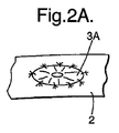
例えば、コロストミー又はイレオストミー等のようなストーマの造設の一般的な処置が、図1、図2A及び図2Bに示されている。図1では、開口部1が腹壁2に形成されているものとして示されている。続いて、腸の端部3Aが開口部1から引き出されている。続いて、腸の端部3Aは、図2Aに示されるように、例えば、コロストミーのために皮膚に「平らに」縫合されてもよい。また、図2Bに示されるように、外側に折り返されて開口部1の外周の一連の縫い目を用いて腹壁2に取り付けられることにより、例えば、「突出型の」イレオストミーとしてストーマ3Bを造設してもよい。
For example, a typical procedure for constructing a stoma such as colostomy or ileostomy is shown in FIGS. 1, 2A and 2B. In FIG. 1, the opening 1 is shown as being formed in the
従来、腹部開口部内側の周りの腹壁は、イレオストミー又はコロストミーの造設時には「補強」されない。全コロストミー及びイレオストミーの30%〜50%は、腹壁に形成された開口部が腹壁を脆弱化する結果として後発的な傍ストーマヘルニア形成を招くと推定されている(英国外科誌(British Journal of Surgery)参照、90巻、7刷、2003年7月)。ストーマの領域の脆弱化した腹壁が時を経て引き伸ばされると、傍ストーマヘルニアができて、その下の腸をストーマに隣接する腹壁から膨出させ得る。 Conventionally, the abdominal wall around the inside of the abdominal opening is not “reinforced” during the construction of ileostomy or colostomy. It is estimated that 30% to 50% of all colostomy and ileostomy result in the subsequent formation of parastomal hernia as a result of the opening formed in the abdominal wall weakening the abdominal wall (British Journal of Surgery ) 90 volumes, 7 printings, July 2003). As the weakened abdominal wall of the stoma area is stretched over time, a parastomal hernia can form and the underlying intestine can bulge from the abdominal wall adjacent to the stoma.
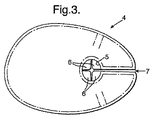
現在のところ、傍ストーマヘルニアができると、患者はその後で大きな外科処置を受けなければならなくなる。極端な場合、これはストーマを腹壁の別の場所に造設し直すことを伴う場合があり、これは高度な技術を要し、高価であり、大きな外傷を与える処置である。それほど極端ではない場合、傍ストーマヘルニアパッチを用いてストーマの部位の周りの腹壁を補強することができる。このようなパッチの1つは、C.R.バード株式会社(C.R. Bard, Inc.)の子会社であるデーヴォル株式会社(Davol Inc.)からバードCK(Bard CK)(商標)傍ストーマヘルニアパッチとして販売されている。このパッチは、傍ストーマヘルニア形成を防止するための予防装置として主に用いるためのものではない。その代わりに、これは主に、発症した傍ストーマヘルニアのパッチの修復のためのものである。図3に示されるように、パッチ4は、破線で示される縫合によってポリプロピレンメッシュ製の対応する形状のシートに取り付けられた延伸ポリテトラフルオロエチレン(ePTFE)のシートから構成されるほぼ楕円形の平坦な材料シートを備えている。パッチの中央の円形領域5は、ePTFE材料のみを含み、ポリプロピレンメッシュは含まず、4つの柔軟な「翼部」6が形成されている。この円形領域5は、腸3を収容するためのものである。パッチの最大部分が傍ストーマヘルニア欠損部を覆い、ePTFE面が内臓面を形成してポリプロピレンメッシュ面が(ストーマの部位の回りの)腹壁と接触する状態でパッチをストーマの部位の周りに位置決めすることができるように、パッチの外縁部(extremity)と円形領域5との間に半径方向スリット7が設けられている。(図4に示される)その最終位置では、4つの柔軟な「翼部」6は、腸がパッチ4の中央領域5を通過する直前の地点で腸の側面に沿って軽く折り曲げられている。パッチ4は、例えば外科用ステープル9を用いて腹壁8の内側に固定される。パッチには、パッチの外周及び中央領域5の周囲に一組のほぼC字形の「形状記憶リコイルリング」が設けられて、パッチが修復部位で跳ね開いてその形状を維持することを補助する。しかしながら、これらのリングは、パッチが(通常は湾曲している)腹壁内側に対して平坦なまま当接しようとするのを助長する。さらに、パッチ4に半径方向スリット7が1つしか設けられておらず、パッチが平坦な性質であることで、外科医は、ストーマ及びヘルニア欠損部の部位の周りの腹壁2の湾曲内面にパッチを一致させるのに苦労する可能性がある。パッチの非内臓面と腹壁の内側との良好な一致及び接触が、腹壁の内側からポリプロピレンメッシュへの組織内方成長を促すのに役立つとともに、パッチが提供する補強のレベルを高めるのに役立つ。
At present, when a parastomal hernia is created, the patient must subsequently undergo major surgery. In extreme cases, this may involve re-establishing the stoma elsewhere in the abdominal wall, which is a highly technical, expensive and traumatic procedure. If not so extreme, a parastomal hernia patch can be used to reinforce the abdominal wall around the stoma site. One such patch is C.I. R. It is sold as a CK (trademark) side stoma hernia patch from Davol Inc., a subsidiary of C.R. Bard, Inc. This patch is not intended primarily for use as a preventive device to prevent parastoma hernia formation. Instead, it is primarily for the repair of the affected parastomal hernia patch. As shown in FIG. 3, the patch 4 is a generally oval flat comprising a sheet of expanded polytetrafluoroethylene (ePTFE) attached to a correspondingly shaped sheet of polypropylene mesh by stitching as indicated by the dashed lines. It is equipped with a material sheet. The central circular region 5 of the patch contains only ePTFE material, no polypropylene mesh, and four flexible “wings” 6 are formed. This circular area 5 is for accommodating the intestine 3. Position the patch around the stoma site with the largest part of the patch covering the parastoma hernia defect and the ePTFE surface forming the visceral surface and the polypropylene mesh surface in contact with the abdominal wall (around the stoma site) In order to be able to do so, a
まず第一に、傍ストーマヘルニアの形成を防止して、傍ストーマヘルニアの修復にコロストミー後又はイレオストミー後の外科処置を行う必要をなくすために、コロストミー又はイレオストミー部位等の補強に用いられる主に予防用の装置が必要である。さらに、腹壁への組み込みのレベル、したがって装置が提供する補強を最大にするために、装置がストーマの部位の周りの患者の腹壁に一致し易い必要がある。コロストミー又はイレオストミー外科処置の時点で、腹腔内で、装置を腸の周りに配置することにより、ヘルニア形成の危険が大幅に低減されるか、又はなくなることさえあるはずである。 First of all, it is mainly used to reinforce a colostomy or ileostomy site to prevent the formation of parastomal hernia and eliminate the need for post-colostomy or post-ileostomy surgery to repair parastomal hernia Equipment is needed. Furthermore, in order to maximize the level of incorporation into the abdominal wall, and thus the reinforcement provided by the device, the device should be easy to conform to the patient's abdominal wall around the stoma site. At the time of a colostomy or ileostomy surgery, placing the device around the intestine within the abdominal cavity should greatly reduce or even eliminate the risk of hernia formation.
本発明の第1の態様によると、患者の腹腔の境界壁のうち、患者の消化管の一部が通過する部位を補強するのに用いられる装置であって、
使用時に前記部位において前記消化管が前記境界壁の内側に入る地点で該消化管の周りに延びるカラー部分と、
前記カラー部分から延びる複数の花弁状要素であって、使用時に前記カラー部分を通過する前記消化管の一部の長手方向軸に対して外方に延びると共に使用時に前記部位の周りの前記境界壁の内側に取り付けられるように配置される複数の花弁状要素と
を備える装置が提供される。
According to a first aspect of the present invention, there is provided a device used to reinforce a portion of a patient's abdominal boundary wall through which a part of a patient's digestive tract passes.
A collar portion extending around the digestive tract at a point where the digestive tract enters the inside of the boundary wall at the site in use;
A plurality of petal-like elements extending from the collar portion, extending outwardly with respect to a longitudinal axis of a portion of the digestive tract passing through the collar portion in use and the boundary wall around the site in use And a plurality of petal-like elements arranged to be attached to the inside.
コロストミー又はイレオストミー等を有する患者の傍ストーマヘルニア形成の防止又は治療に本装置が用いられる場合、境界壁は患者の腹壁であり、消化管の一部は患者の腸であり、部位はストーマの部位である。 When this device is used to prevent or treat parastoma hernia formation in patients with colostomy or ileostomy, the boundary wall is the patient's abdominal wall, part of the digestive tract is the patient's intestine, and the site is the stoma site It is.
本装置は、既知の合併症を制限又は低減するための予防装置として用いられることで、大きな財務費用、後発の合併症、及び患者の外傷をなくすことが主に意図されるが、以前のコロストミー又はイレオストミー処置の部位において発症した傍ストーマヘルニアの修復を行うための修正外科手術で本装置を用いることができることも意図されている。 Although the device is primarily intended to eliminate significant financial costs, late complications, and patient trauma by being used as a preventive device to limit or reduce known complications, It is also contemplated that the device can be used in revision surgery to repair parastomal hernia that has developed at the site of ileostomy treatment.
しかしながら、発症した裂孔ヘルニアの修復に本装置を用いる場合、境界壁は患者の横隔膜であり、消化管の一部は横隔膜を通過する地点の患者の食道である。 However, when the device is used to repair an inguinal hiatal hernia, the boundary wall is the patient's diaphragm and a portion of the gastrointestinal tract is the patient's esophagus at the point of passage through the diaphragm.
本発明の第2の態様によると、患者の腹腔の境界壁のうち、患者の消化管の一部が通過する部位を補強する方法であって、
上記の本発明の第1の態様の装置を準備することと、
複数の花弁状要素を前記部位の周りの前記境界壁の内側と接触させながら、前記部位において前記消化管が前記境界壁の内側に入る地点で前記消化管の周りに前記カラー部分を形成することと、
前記複数の花弁状要素を前記部位の周りの前記境界壁の接触する内側に締結することと
を含む方法が提供される。
According to a second aspect of the present invention, there is provided a method for reinforcing a portion of a boundary wall of a patient's abdominal cavity through which a part of a patient's digestive tract passes,
Providing the apparatus of the first aspect of the invention as described above;
Forming the collar portion around the gastrointestinal tract at a point where the gastrointestinal tract enters the inside of the boundary wall at the site while contacting a plurality of petal-like elements with the inside of the boundary wall around the site; When,
Fastening the plurality of petal-like elements to the contacting inside of the boundary wall around the site.
本発明の第3の態様によると、上記の本発明の第1の態様の装置を製造する方法であって、
a)生体適合性プラスチック材料のシートを準備することと、
b)成形及び切断によって前記シートから前記カラー部分及び前記複数の花弁状要素を形成することと
を含む方法が提供される。
According to a third aspect of the present invention, there is provided a method for manufacturing the apparatus according to the first aspect of the present invention, comprising:
a) preparing a sheet of biocompatible plastic material;
b) forming the collar portion and the plurality of petaloid elements from the sheet by molding and cutting.
次に、例としてのみ、添付図面を参照して本発明による装置の実施形態を説明する。 Embodiments of the device according to the invention will now be described by way of example only with reference to the accompanying drawings.
装置10の第1の実施形態、理想的には傍ストーマヘルニア予防装置を、図5〜図8に示す。明らかとなるように、装置の1つの用途は、例えば、コロストミー又はイレオストミー造設処置においてストーマを形成するために患者の腸が患者の腹壁に通される部位の補強である。これは、例として後述する処置である。上述のように、コロストミー又はイレオストミーに関連して用いられる場合、装置10は、後発的な傍ストーマヘルニア形成の危険をなくす(又は少なくとも大幅に減らす)ように、最初のコロストミー又はイレオストミー処置中に植え込まれる予防装置として用いられることが主に意図される。しかしながら、装置10は、傍ストーマヘルニア又は裂孔ヘルニアのような既存のヘルニア欠損部を治療するための後続の修正外科手術で用いられてもよい。
A first embodiment of the
以下の説明の大部分では、傍ストーマヘルニア予防装置としての装置の使用を説明するが、この説明は例としてのものにすぎず非限定的なものである。簡素化のために、(本明細書中の他の部分で述べられている)その装置の他の可能な臨床用途には引き続き言及しない。例えば、腹壁及び腸という用語が用いられる場合、発症した裂孔ヘルニアの治療にその装置が用いられているとすれば、これらの用語は、代わりに横隔膜及び食道を指すのと同等である。 Most of the following description describes the use of the device as a parastomal hernia prevention device, but this description is only an example and is non-limiting. For simplicity, we will not continue to mention other possible clinical uses of the device (described elsewhere herein). For example, when the terms abdominal wall and intestine are used, if the device is used to treat an onset of hiatal hernia, these terms are equivalent to referring to the diaphragm and esophagus instead.
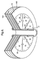
少なくとも使用の直前には、図5に示されるように、装置10は、使用時にストーマの部位において腸が腹壁の内側に入る地点で腸の周りに延びる、ほぼ管状のカラー部分11を備えている。装置10は、カラー部分11の管の長手方向軸13に対してほぼ半径方向にカラー部分11の一端から延びる、複数の(図示された実施形態では8つの)ほぼ平面状の花弁状要素12をさらに備えている。明らかとなるように、花弁状要素12は、長手方向軸13に対してほぼ半径方向に延びるのに加えて、使用時にカラー部分11を通過する腸(図5には図示せず)の部分の長手方向軸に対してほぼ半径方向外方に延びるが、これは、2つの長手方向軸が使用時にほぼ同軸上にあるからである。「ほぼ半径方向外方に」延びるとは、かなりの半径方向成分を有して延びることを意味するものであり、この用語は、純粋又はほぼ純粋に半径方向に延びることを単に意味するのではない。
At least immediately prior to use, as shown in FIG. 5, the
また後ほど明らかとなるように、花弁状要素12は、使用時に、ストーマの部位の周りの腹壁の内側の形状に一致させ易くすることができるとともに、ステープル又は縫合糸のような従来既知の締結手段を用いて腹壁の内側に取り付けることができるように、可撓性であり、独立に操作可能である。
Also, as will become apparent later, the petal-
カラー部分11はほぼ管状であるが、その軸方向全長に沿って半径方向のギャップ14が設けられ、これは、これがなければほぼ回転対称である装置から「欠けている」扇形に相当することを留意されたい。このギャップ14は、ギャップ14に腸を通過させることによって、使用時に腸の周りに装置を嵌めることを可能にするためのものであり、図7Aに示されるように、使用時にカラー部分11内に収容される腸の部分に(腸の腸間膜28を介して)血液を連続供給するために、腸間膜を通すギャップをカラー部分11に設けるためのものでもある。
The
より詳細に後述するように、個々の花弁状要素12は、ほぼ半径方向に向いたスリット15によって互いに離隔されている。図5は、植え込み直前の装置に見込まれる構成を示している。しかしながら、装置10は、代替的に、異なる構成で、例えば無菌可剥性の熱成形トレー内に装置をコンパクトに梱包するのにより適合性のある、部分的又は完全に扁平な構成で外科医に提供され、外科医又は外科助手は、その装置を植え込み前に操作して図5に示される最終構成にすることを必要としてもよい。
As will be described in more detail below, the individual petal-
次に、図5の装置の植え込みの例示的な処置を、例としてコロストミー又はイレオストミー処置の一部として説明する。その装置はストーマの造設後に植え込まれ、その部位を装置10が補強することになる。植え込みは、(その装置が予防装置であることが意図される場合)ストーマの造設と同じ外科処置中に行われてもよく、又は既存の傍ストーマヘルニア欠損部を修復するように後続の修正外科手術中に行われてもよい。その処置は、予防装置としての装置の使用に関連して説明するが、花弁状要素12がヘルニア欠損部を覆い欠損部よりもいくらか大きい距離だけ(例えば3cm〜5cm)延びて位置決めされたことを外科医が確認する必要があることを除いて、修正外科手術で用いられる処置もほぼ同様である。
An exemplary procedure for implanting the device of FIG. 5 will now be described by way of example as part of a colostomy or ileostomy procedure. The device is implanted after the stoma is constructed, and the
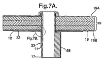
ストーマの部位において腸が腹壁の内側に入る地点にある腸の部分にアクセスすると、外科医はまず、適当なサイズの装置を選択してから装置10を正しい向きにする必要がある。装置10の正しい向きは、花弁状要素12が設けられたカラー部分11の端部が腹壁の内側の最も近くに位置決めされた状態である。装置10がこの向きになると、装置10は、カラー部分11のギャップ14に腸の上記部分を半径方向に通過させることによって、腸の上記部分の周りに位置決めされる。これが行われると、(可撓性である)装置10のカラー部分11を腸の上記部分の周りで閉じて、カラー部分11のほぼ円筒形の内(非内臓)壁を腸部分の外側と密着接触させることができる。図7Aに示されるように、このときカラー部分11に収容されている上記収容された腸部分の腸間膜28は、カラー部分11のギャップ14と位置合わせされてギャップ14を貫通することができ、腹壁内側の内部で切り取られる必要がないことにより、腸の収容部分に栄養を供給し続けることができる。必要であれば、ギャップ14は、外科医がカラー部分11の材料の一部を切り取ることによって拡大させることができる。図6、図7A、及び図7Bに示されるように、装置10のこの最終位置では、花弁状要素12の非内臓面16は、ストーマの部位の周りの腹壁19の内面18と接触し、花弁状要素12が可撓性であることにより腹壁の内面の内部形状(多くの場合はほぼ凹状)に正確に一致することができる。図面では、腹壁19は、薄い外層19A(表皮)と薄い内層19B(腹膜)との間に挟まれた3つの主層から構成されるものとして示されている。
When accessing the part of the intestine where the intestine is inside the abdominal wall at the site of the stoma, the surgeon must first select an appropriately sized device and then direct the
花弁状要素12間にスリット15を設けることで、スリット15が存在せず、その代わりに花弁状要素12が1枚の連続した平面状のC字形シートである場合の状況とは対照的に、花弁状要素12を互いに独立して撓ませることができるとともに、大きな皺ができずに腹壁19の内部形状により一致し易くすることができることが理解されるであろう。花弁状要素12と腹壁19の内部形状との一致を改善することによって、花弁状要素12の非内臓面16と腹壁19の内面18との接触面積を増やすことができ、それにより、後述するように腹壁19から花弁状要素12への組織内方成長の可能性を高めることができる。腹壁19に花弁状要素12が組み込まれる可能性をこのように高めることで、装置10が提供する腹壁19の補強のレベルが高まる。
By providing a
装置10がその最終位置になると、外科医は、既知の締結手段及び技術(例えば、ステープル、タック、又は縫合糸20、図6を参照)を用いて、ストーマの部位の周りの腹壁の内側に花弁状要素12を固定することができる。
When the
必須ではないと考えられるが、カラー部分11は、例えば(図示しない)非吸収性縫合糸を用いて、収容された腸部分17に取り付けられてもよい。これは、装置10が提供する皮膚表面19Aへの腸の案内及び方向付けのレベルの向上、及び腸重積によるヘルニア形成の危険の低減に有利であり得る。
Although not considered essential, the
図7Aは、腸の腸間膜28が装置10のカラー部分11の(図示しない)ギャップ14を貫通していることを示している。腸17の収容部分に支持を与えるために、カラー部分11の内(非内臓)面21及び腸17の収容部分の外面が互いに密着接触する。図7A、及び特に図7Bは、腹壁19の内面18に面する花弁状要素12の(非内臓)面16が内面18と接触していることも示している。図7Aは、腸17の収容されたストーマ造設部分に、腹壁19の内面18まで腸間膜28が設けられたままである様子も示している。腹壁19の開口部内に収容された腸の部分が腹壁層から血液供給を受けることができるため、腸間膜28が腹壁19内まで延びる必要はない。
FIG. 7A shows that the
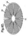
花弁状要素12及びカラー部分11はいずれも、装置10の使用時に患者の内部器官すなわち内臓に面することになる内臓面(それぞれ22及び23)を有している。体腔内の内部器官と装置10との間の接着は、非常に望ましくない。したがって、花弁状要素12及びカラー部分11の内臓面22、23が、望ましくない組織の接着を最小限にする材料を含むか又は少なくともこれに面することが有利である。好適な実施形態では、この材料24は、ポリテトラフルオロエチレン又は延伸ポリテトラフルオロエチレン材料のシートである。しかしながら、材料24は、「非粘着性」であるとみなされる任意の他の適切な生体適合性材料であってもよい。
Both the
花弁状要素12はそれぞれ、花弁状要素12の内臓面22とは逆の方向に面する非内蔵面16を有している。図7A及び図7Bに示されるように、花弁状要素12のこれらの非内蔵面16は、使用時に腹壁19の内面18に接触する。装置10によってストーマの付近の腹壁19に与えられる補強のレベルを最大にするために、腹壁から花弁状要素12の非内蔵面16への組織内方成長があることが非常に望ましい。このように、花弁状要素12は、腹壁19に補強を提供するように腹壁19に組み込まれるようになる。
Each petal-
花弁状要素12の非内蔵面16への組織内方成長を促すために、これらの面は、組織内方成長を促進させる材料25を備えるか又は少なくともこれに面する。好適な実施形態では、花弁状要素12の非内蔵面16は、露出したポリプロピレンメッシュ状の材料25を備える。このメッシュ状の材料25は、図8A、図8D、図9A、及び図9Dにおいて十字模様で表されている。メッシュ状の材料25は、むき出しの露出したポリプロピレンメッシュであってもよいが、代替的に、粘着性であることによって外科手術中に腹部への装置10の接着を促すとともに止血材として働くために、コラーゲン又はゼラチン等が埋め込まれたポリプロピレンメッシュのシートを備える場合もある。
In order to promote tissue ingrowth to the
花弁状要素12の内臓面22及び非内蔵面16に異なる特性を与えるために、花弁状要素12はそれぞれ、図示されるように、2枚の材料24、25のシートから成ることが好ましい。図8A及び図8Dから見ることができるように、(「十字模様」として示される)メッシュ状の材料25は、非粘着性材料24の上に重ねられ、非粘着性材料がメッシュ状の材料の境界を越えて延びている。2つの材料24、25は、縫合又は接着等によって互いに固定されることが有利である。メッシュ状の材料25の外周を越えて延びることによって、非粘着性材料24は、望ましくない瘻孔形成を助長し得る内臓との不慮の接触からメッシュ状の材料の切断縁部を保護する。
In order to provide different characteristics to the
カラー部分11の非内蔵(内)面21は、腸17の収容部分からの組織内方成長を促進させるべきではないと考えられている。腸17からカラー部分11への組織内方成長は、望ましくない瘻孔形成につながり得るため抑えたほうがよいと考えられる。さらに、装置10の除去及び交換が必要な場合は常に、腸17の収容部分からカラー部分11の非内蔵面21への組織内方成長が装置10の除去を複雑にするであろう。
It is believed that the non-built-in (inner)
この理由から、装置10のカラー部分11の非内蔵(内)面21は、カラー部分11の内臓(外)面23と同じ非粘着性を有することが有利である。図7Bに示されるように、これは、非粘着性材料の厚さを一様にして、その両面が非内蔵面21及び内蔵面23の両方を形成するようにすることによって達成することができる。
For this reason, the non-built-in (inner)
図5から見ることができるように、使用前の装置10は、上部が開いたシルクハットに全体的に類似しているが、大きなつばに複数の(図では8つの)半径方向に向いたスリット15が設けられており、1つの半径方向に向いたスリット14、15が完成した「ハット」に延びている。
As can be seen from FIG. 5, the
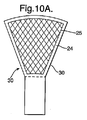
装置10をこの3D形状に形成するために、ほぼ非粘着性の材料24をこの所望の形態に成形することができる。代替的に、装置10は、複数の構成要素から形成することができる。次に、図10Aを参照してこのような技術の1つを説明する。
In order to form the
最初に、非粘着性材料24の複数のY字形要素30を、例えば、非粘着性材料の大型シートから打ち抜くこと又は切り抜くことによって形成する(図10A参照)。続いて、メッシュ状の材料25の一部を、例えば、接着又は縫合によってY字形要素30のそれぞれの広がり端部に固定する。材料25の十字模様は、図10Aには示されているが図10Bには示されていない。これらの広がり端部は、使用時に、装置10のほぼ平面状の花弁状要素12を形成する。続いて、Y字形要素30は、(図10Bに示すように)一列に配置され、例えば接着又は縫合によって互いに固定される。図10Bには、このようなY字形要素30が3つしか示されていないが、完成した装置10の花弁状要素12と同じ数だけY字形要素30が継ぎ合わせられる。
First, a plurality of Y-shaped
継ぎ合わせられたY字形要素30は、使用時に、装置10のカラー部分11を形成するのに用いられる。代替的に又は付加的に、互いに縫合されたステムに非粘着性材料のパッチを縫い付けてもよい。さらに別の代替形態として、装置10のカラー部分11の大部分が、一定の1枚のシートの厚さになるように、Y字形要素30の重なり部分の大部分を非粘着性材料のパッチへの縫合前に切り取ることができる。このさらなる材料のパッチは、完成したカラー部分11を形成するようにスリットの入った円筒形状に形成されるか又は形成することができる矩形パッチであってもよい。
The seamed Y-shaped
装置10をほぼシルクハット形状に形成するために、Y字形要素30のそれぞれを線32に沿ってほぼ直角に折り曲げてから、ほぼ円筒形のカラー部分11を形成するように軸13を中心に装置10を整形することによって、装置10を図10Bに示されるほぼ2D構造から図5に示されるほぼシルクハット形状の3D構造に変えることができる。装置10の操作を助けるために、装置10がその最終のシルクハット形状になるように操作されている間に、既知の方法で熱を加えてもよい。
In order to form the
装置10の花弁状要素12及びカラー部分11に適した他の生体適合性材料は明らかであろう。例えば、組織内方成長を促進させる生体適合性材料は、ポリプロピレン、ダクロン、シリコン、ポリエチレン、ポリアミド、チタン、ステンレス鋼、ポリメチルメタクリレート、又はポリウレタンから成る群より選択される異なる非吸収性構造材料であってもよい。非粘着性材料としてのPTFE又はePTFEの代替物は、非粘着性であるとみなされる任意の他の適切な生体適合性材料であってもよい。
Other biocompatible materials suitable for the petal-
使用時には、図6に最も明確に示されるように、隣接する花弁状要素12の対向する側方縁部間で患者の腹壁の内側の三角形領域が露出されたままになる。装置10が提供する補強を高めるために、患者の腹壁内側のうち、使用時に花弁状要素12間で露出したままとなる領域を減らすか又はなくすことが望ましいであろう。これは、花弁状要素12が腹壁19の内面18に締結されるとほぼ連続的なO字形又はC字形の補強要素を形成するように、使用時に、例えば当接するか又は重なりさえするように、花弁状要素12を図示されるよりも大きくすることによって達成することができる。この状況では、重なりによって、縫合糸、タック、又はステープルのような締結具20を重なり区域に貫通させることができる。
In use, the triangular area inside the patient's abdominal wall remains exposed between opposing lateral edges of adjacent petal-
上述したように、個々の花弁状要素12間にスリット15を設けることで、花弁状要素12を患者の腹壁19の内面18の不規則な内部形状に、より一致し易くすることができる。例えば、患者の腹壁の内側が(腹壁の内側から見た場合に)ほぼ凹状である場合、個々の可撓性の花弁状要素12を腹壁の形状に従うように一致させてから腹壁に容易に締結させることができる。花弁状要素12の非内蔵面と腹壁との間の接触面積を増やすことによって、花弁状要素12への組織内方成長を強化することができる結果として、装置10が提供する補強のレベルを高めることができる。さらに、複数の個々の花弁状要素12を設けることで、腸17とカラー部分11の非内蔵面21との間に止まり嵌めを形成することができる装置の能力を高めて、カラー部分がその長さに沿って腸の収容部分に取り付けられて腸重積の防止を助けることができる。
As described above, by providing the
装置10は、種々の外周寸法の腸に適応するように様々なサイズで設けることが想定されている。さらに、花弁状要素12の半径方向の範囲は、装置ごとに変わり得る。例えば、予防用の装置は、修正外科手術用の装置よりも、花弁状要素12の半径方向の範囲が小さくてもよいが、これは、修正外科手術の場合には、花弁状要素12が傍ストーマヘルニア欠損部よりも大きな範囲にわたって延びる必要があるからである。外科処置の開始時には、外科医が様々な異なる寸法の装置から患者の生理機能に基づいた幾何学的形状に最もよく合う装置を選択することが想定されている。さらに、花弁状要素12の全てが同じ半径方向の範囲を有するとは限らない。特に、修正外科手術で用いられる場合、欠損部を覆う花弁状要素12は、より大きくして、例えば組み合わせた要素に円形というよりも楕円形の外観を与えるようにしてもよい。
It is envisioned that the
図では、カラー部分11がほぼ管状でありかなり細長いものとして示されているが、そのように長い長さである必要はない。例えば、カラー部分11は、腹壁19に設けられた開口部に腸17が入る直前に腸17を十分に支持する必要がない場合には、花弁状要素12を一列につなぎ合わせて保持して腸と半径方向に接触させるとともに半径方向の最も内側端部で支持することができる手段としての役割を果たすように、軸方向の範囲が最小のC字形要素であるにすぎなくてもよい。
In the figure, the
図5〜図8に示される装置10の第1の実施形態では、装置は8つの花弁状要素12が設けられるものとして示されているが、他の個数の要素が設けられもよい。例えば、図9A〜図9Dに示されるように、これらの花弁状要素12の数を減らして、個々の要素のサイズを大きくしてもよい。図9A及び図9Dは、装置10に設けられたギャップ14が図5〜図8の実施形態よりもかなり大きい様子も示している。
In the first embodiment of the
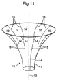
装置10は、図10A及び図10Bに関連して説明するように、複数の構成要素から形成される必要はなく、カラー部分11から鋭く直角に延びる平坦な平面状シートの形態の花弁状要素12を有する必要もない。図11に示される装置10の第3の実施形態では、使用前の独立状態のときに、装置10がトランペットの円錐端部に全体的に類似し得る様子を見ることができる。トランペットのベルに設けられた複数のスリット15が、8つの花弁状要素12を互いに分離する。隠れている後方のスリット15の組の下部は、破線で示されている。装置10の先行する実施形態のギャップ14と同じ理由で、装置10の全長にわたって半径方向のギャップ14が設けられている。当然ながら、装置10の第1の実施形態及び第2の実施形態とは対照的に、装置10の第3の実施形態では、カラー部分11と花弁状要素12との間はアール状に徐々に遷移している。カラー部分11から最も遠い花弁状要素12の遠位部分は、カラー部分11の長手方向軸に対してほぼ垂直であるが、花弁状要素12の近位部分(カラー部分に近い)は角度がより小さいことが理解されるであろう。
トランペットの円錐端部に全体的に似ている装置10の1つの利点は、1枚の材料シートから装10置を形成するのに特に適していることである。1枚の材料シートを用いてそれを成形することにより、例えば、圧力及び熱の両方を施して熱成形することにより、ほぼ平坦な材料シートがトランペットの円錐端部に似ている図示された形状を帯びるようにすることができる。花弁状要素12を分離するスリット15は、成形前に平坦なシートに形成してもよく、又はシートが円錐端部形状に成形された後でシートに形成してもよい。
One advantage of the
シートを熱成形して装置10にすることは、熱可塑性材料に非常に適している。成形されるシートは、(第1の実施形態及び第2の実施形態のように)異なる特性を有する複数のシートから構成される複合材であってもよいが、成形技術は、装置のシート材料が異なる材料の異なる層から成る複合材ではなくほぼ均一な構成を有する1枚の材料シートである場合の装置の形成に特に適している。このような材料の1つは、モティフメッシュ(Motifmesh)という商標でプロキシバイオメディカル社(Proxy Biomedical Limited)によって製造されているような架橋ポリテトロフルオロエチレン(cPTFE)のシートであろう。モティフメッシュ材料は、大孔径のモノフィラメントポリプロピレンメッシュの有利な内方成長及び治癒創傷強度特性を延伸PTFEパッチの生体適合性及び低接着属性と組み合わせたものである。モティフメッシュ材料は、平均孔径が2400μmで厚さが0.15mmの開孔構造(open pore structure)を有する。モティフメッシュ材料のさらなる詳細は、プロキシバイオメディカル社の国際公開第2004/006808号明細書で見ることができ、その内容は参照により本明細書に援用される。
Thermoforming the sheet into
cPTFEモティフメッシュ材料のような1枚の材料シートからの装置10の製造は、図11に示される全体的な装置構成を有し上記の成形技術によって製造される装置に特に適しているが、第1の実施形態及び第2の実施形態で用いることもできる。換言すれば、第1の実施形態及び第2の実施形態の全体的な幾何学的形状を有する装置は、複数の別個の構成要素から製造される必要はなく、互いに取り付けられた異なる材料の複数の層を含む材料から製造される必要もない。
The manufacture of
本装置は、コロストミー又はイレオストミー等を有する患者における傍ストーマヘルニアの防止又は治療に関連して説明したが、消化管の他の部分が患者の腹腔の境界を通過する部位において発症したヘルニアの修復に用いることもできる。例えば、本装置のカラー部分を患者の食道の周りに嵌め(カラーを患者の胃に向かって下方に延ばし)、ほぼ平面状の要素を患者の横隔膜の下側に締結することにより、発症した傍ストーマヘルニアの修復に用いることができるのとほぼ同じように、発症した裂孔ヘルニアの修復に本装置を用いることができる。発症した裂孔ヘルニアの修復に用いられる場合、本装置は、傍ストーマヘルニアの防止又は修復に用いられる場合よりも小さくなり、例えば、カラー部分の直径のサイズが小さくカラー部分の長手方向範囲の長さが短いことが想定される。 Although this device has been described in connection with the prevention or treatment of parastomal hernia in patients with colostomy or ileostomy, etc., this device can be used to repair hernias that develop at sites where other parts of the gastrointestinal tract cross the peritoneal border of the patient. It can also be used. For example, the collar portion of the device is fitted around the patient's esophagus (the collar extends downwardly toward the patient's stomach) and the approximately planar element is fastened to the underside of the patient's diaphragm, thereby developing The device can be used to repair a hiatal hernia just as it can be used to repair a stoma hernia. When used to repair a hiatal hernia that has developed, the device is smaller than when used to prevent or repair a parastomal hernia, for example, the diameter of the collar portion is smaller and the length of the longitudinal range of the collar portion is smaller. Is assumed to be short.
Claims (49)
使用時に前記部位において前記消化管が前記境界壁の内側に入る地点で該消化管の周りに延びるカラー部分と、
前記カラー部分から延びる複数の花弁状要素であって、使用時に前記カラー部分を通過する前記消化管の一部の長手方向軸に対して外方に延びると共に使用時に前記部位の周りの前記境界壁の内側に取り付けられるように配置される複数の花弁状要素と
を備える装置。 A device used to reinforce a portion of a patient's abdominal boundary wall through which a part of a patient's digestive tract passes,
A collar portion extending around the digestive tract at a point where the digestive tract enters the inside of the boundary wall at the site in use;
A plurality of petal-like elements extending from the collar portion, extending outwardly with respect to a longitudinal axis of a portion of the gastrointestinal tract passing through the collar portion in use and the boundary wall around the site in use And a plurality of petal-like elements arranged to be mounted inside.
前記カラー部分に最も近い近位部分と、
前記カラー部分から最も遠い遠位部分と
を有し、
前記花弁状要素の少なくとも前記遠位部分は、使用時に前記長手方向軸に対してほぼ半径方向外方に延びるように配置される、請求項1に記載の装置。 The petal-like element is
A proximal portion closest to the collar portion;
A distal portion furthest from the collar portion;
The apparatus of claim 1, wherein at least the distal portion of the petal-like element is arranged to extend generally radially outward relative to the longitudinal axis in use.
使用時に患者の内部器官に面する内臓面と、
前記部位の周りの前記境界壁の内側に面する非内臓面と
を有し、
前記複数の花弁状要素の前記内臓面は、内臓の接着を最小限にする材料を含む、請求項23〜25のいずれか一項に記載の装置。 Each of the plurality of petal-like elements is
Visceral surface facing the patient's internal organs in use;
A non-internal surface facing the inside of the boundary wall around the site;
26. The device according to any one of claims 23 to 25, wherein the visceral surface of the plurality of petal-like elements comprises a material that minimizes visceral adhesion.
使用時に患者の内部器官に面する内臓面と、
前記カラー部分を通過する前記消化管の一部に面する非内臓面と
を有し、
前記カラー部分の前記内臓面は、内臓の接着を最小限にする材料を含む、請求項23〜30のいずれか一項に記載の装置。 The color portion is
Visceral surface facing the patient's internal organs in use;
A non-in visceral surface facing a portion of the digestive tract that passes through the collar portion;
31. A device according to any one of claims 23 to 30, wherein the visceral surface of the collar portion comprises a material that minimizes visceral adhesion.
請求項1〜40のいずれか一項に記載の装置を準備することと、
前記複数の花弁状要素を前記部位の周りの前記境界壁の内側と接触させながら、前記部位において前記消化管が前記境界壁の内側に入る地点で前記消化管の周りに前記カラー部分を形成することと、
前記複数の花弁状要素を前記部位の周りの前記境界壁の接触する内側に締結することと
を含む方法。 A method of reinforcing a part of the patient's abdominal boundary wall through which a part of the patient's digestive tract passes,
Preparing an apparatus according to any one of claims 1 to 40;
Forming the collar portion around the gastrointestinal tract at a point where the gastrointestinal tract enters the inside of the boundary wall at the site while contacting the plurality of petal-like elements with the inside of the boundary wall around the site And
Fastening the plurality of petal-like elements to the contacting inside of the boundary wall around the site.
b)成形及び切断によって前記シートから前記カラー部分及び前記複数の花弁状要素を形成することと
を含む、請求項1〜40のいずれか一項に記載の装置を製造する方法。 a) preparing a sheet of biocompatible plastic material;
41. A method of manufacturing an apparatus according to any one of claims 1 to 40, comprising b) forming the collar portion and the plurality of petaloid elements from the sheet by molding and cutting.
Applications Claiming Priority (2)
| Application Number | Priority Date | Filing Date | Title |
|---|---|---|---|
| GB0519095A GB2430372B (en) | 2005-09-19 | 2005-09-19 | Reinforcement device |
| PCT/GB2006/003410 WO2007034145A2 (en) | 2005-09-19 | 2006-09-14 | Abdominal reinforcement device |
Related Child Applications (1)
| Application Number | Title | Priority Date | Filing Date |
|---|---|---|---|
| JP2012006536U Continuation JP3180827U (en) | 2005-09-19 | 2012-10-26 | Reinforcing device |
Publications (2)
| Publication Number | Publication Date |
|---|---|
| JP2009508610A true JP2009508610A (en) | 2009-03-05 |
| JP2009508610A5 JP2009508610A5 (en) | 2009-11-05 |
Family
ID=35249035
Family Applications (2)
| Application Number | Title | Priority Date | Filing Date |
|---|---|---|---|
| JP2008531768A Pending JP2009508610A (en) | 2005-09-19 | 2006-09-14 | Reinforcing device |
| JP2012006536U Expired - Fee Related JP3180827U (en) | 2005-09-19 | 2012-10-26 | Reinforcing device |
Family Applications After (1)
| Application Number | Title | Priority Date | Filing Date |
|---|---|---|---|
| JP2012006536U Expired - Fee Related JP3180827U (en) | 2005-09-19 | 2012-10-26 | Reinforcing device |
Country Status (8)
| Country | Link |
|---|---|
| US (1) | US20090299388A1 (en) |
| EP (1) | EP1926457A2 (en) |
| JP (2) | JP2009508610A (en) |
| CN (1) | CN101312697B (en) |
| AU (1) | AU2006293719B2 (en) |
| CA (1) | CA2622921A1 (en) |
| GB (1) | GB2430372B (en) |
| WO (1) | WO2007034145A2 (en) |
Cited By (5)
| Publication number | Priority date | Publication date | Assignee | Title |
|---|---|---|---|---|
| JP2011505220A (en) * | 2007-12-03 | 2011-02-24 | ソフラディム・プロデュクスィヨン | Implants for parastomal hernia |
| JPWO2020196856A1 (en) * | 2019-03-28 | 2020-10-01 | ||
| JPWO2020196885A1 (en) * | 2019-03-28 | 2020-10-01 | ||
| JPWO2020196857A1 (en) * | 2019-03-28 | 2020-10-01 | ||
| WO2020196887A1 (en) * | 2019-03-28 | 2020-10-01 | テルモ株式会社 | Medical device |
Families Citing this family (32)
| Publication number | Priority date | Publication date | Assignee | Title |
|---|---|---|---|---|
| ES2380249T3 (en) * | 2006-09-12 | 2012-05-09 | Feg Textiltechnik Forschungs- Und Entwicklungsgesellschaft Mbh | Single piece stoma support implant and manufacturing procedure |
| US8623034B2 (en) | 2007-10-19 | 2014-01-07 | Ethicon, Gmbh | Soft tissue repair implant |
| US9308068B2 (en) | 2007-12-03 | 2016-04-12 | Sofradim Production | Implant for parastomal hernia |
| CA2706865C (en) * | 2007-12-03 | 2015-11-24 | Sofradim Production | Implant for parastomal hernia |
| US9393002B2 (en) | 2008-02-18 | 2016-07-19 | Covidien Lp | Clip for implant deployment device |
| US9301826B2 (en) | 2008-02-18 | 2016-04-05 | Covidien Lp | Lock bar spring and clip for implant deployment device |
| EP2247245B1 (en) | 2008-02-18 | 2017-06-28 | Covidien LP | A device for deploying and attaching a patch to a biological tissue |
| US8317808B2 (en) | 2008-02-18 | 2012-11-27 | Covidien Lp | Device and method for rolling and inserting a prosthetic patch into a body cavity |
| US9034002B2 (en) | 2008-02-18 | 2015-05-19 | Covidien Lp | Lock bar spring and clip for implant deployment device |
| US8808314B2 (en) | 2008-02-18 | 2014-08-19 | Covidien Lp | Device and method for deploying and attaching an implant to a biological tissue |
| US9393093B2 (en) | 2008-02-18 | 2016-07-19 | Covidien Lp | Clip for implant deployment device |
| US9833240B2 (en) | 2008-02-18 | 2017-12-05 | Covidien Lp | Lock bar spring and clip for implant deployment device |
| US9398944B2 (en) | 2008-02-18 | 2016-07-26 | Covidien Lp | Lock bar spring and clip for implant deployment device |
| US9044235B2 (en) | 2008-02-18 | 2015-06-02 | Covidien Lp | Magnetic clip for implant deployment device |
| US8758373B2 (en) | 2008-02-18 | 2014-06-24 | Covidien Lp | Means and method for reversibly connecting a patch to a patch deployment device |
| EP2792307B1 (en) | 2008-10-20 | 2017-10-04 | Covidien LP | A device for attaching a patch to a biological tissue |
| EP2467066B1 (en) | 2009-08-17 | 2019-03-27 | Covidien LP | Means for reversibly connecting an implant to a deployment device |
| WO2011021083A1 (en) | 2009-08-17 | 2011-02-24 | PolyTouch Medical, Inc. | Articulating patch deployment device and method of use |
| BE1019267A3 (en) * | 2010-03-31 | 2012-05-08 | Gols Johan De | GAS ASSEMBLY FOR STRENGTHENING TISSUE THAT EXPECTS A SURGERY-CREATED STOMA. |
| US8449512B2 (en) * | 2010-04-09 | 2013-05-28 | Davinci Biomedical Research Products Inc. | Stoma stabilitating device and method |
| US8790322B2 (en) * | 2010-08-03 | 2014-07-29 | King Saud University | Stoma coat |
| FR2977790B1 (en) * | 2011-07-13 | 2013-07-19 | Sofradim Production | PROSTHETIC FOR UMBILIC HERNIA |
| HU230051B1 (en) * | 2012-01-31 | 2015-06-29 | Replant Cardo Kft | Device for prevention of a parastomal hernia and method for using thereof |
| US20140114266A1 (en) * | 2012-10-22 | 2014-04-24 | Ams Research Corporation | Ostomy Implant System and Method |
| FR3008884B1 (en) * | 2013-07-25 | 2017-01-06 | Cousin Biotech | IMPLANTABLE PROSTHESIS |
| EP3148486B1 (en) | 2014-05-28 | 2018-07-11 | Coloplast A/S | An ostomy wafer |
| US9622844B2 (en) | 2014-10-31 | 2017-04-18 | Prevent Patch, LLC | Devices and methods for preventing incisional hernias |
| US9895212B2 (en) | 2014-10-31 | 2018-02-20 | Prevent Patch LLC | Devices and methods for preventing incisional hernias |
| RU2712075C2 (en) | 2015-03-16 | 2020-01-24 | Колопласт А/С | Stoma apparatus |
| CN104706442B (en) * | 2015-03-16 | 2017-08-01 | 克力木·阿不都热依木 | The special sticking patch of hiatal hernia |
| US10603154B2 (en) | 2015-03-31 | 2020-03-31 | Prevent Patch, LLC | Devices and methods for preventing incisional hernias |
| WO2024006420A1 (en) * | 2022-06-30 | 2024-01-04 | Davol Inc. | Implantable prosthesis |
Citations (4)
| Publication number | Priority date | Publication date | Assignee | Title |
|---|---|---|---|---|
| US4854316A (en) * | 1986-10-03 | 1989-08-08 | Davis Emsley A | Apparatus and method for repairing and preventing para-stomal hernias |
| JP2002507901A (en) * | 1997-06-25 | 2002-03-12 | ビオタップ アー/エス | Skin-to-skin transplant device |
| JP2002522112A (en) * | 1998-07-31 | 2002-07-23 | シー・アール・バード・インコーポレーテッド | Prosthesis for hernia surgery |
| JP2003505191A (en) * | 1999-07-28 | 2003-02-12 | シー・アール・バード・インコーポレーテッド | Hernia prosthesis |
Family Cites Families (19)
| Publication number | Priority date | Publication date | Assignee | Title |
|---|---|---|---|---|
| GB1595811A (en) * | 1978-02-07 | 1981-08-19 | Johnson & Johnson | Stoma adaptor |
| US4403604A (en) * | 1982-05-13 | 1983-09-13 | Wilkinson Lawrence H | Gastric pouch |
| US5441508A (en) * | 1989-04-27 | 1995-08-15 | Gazielly; Dominique | Reinforcement and supporting device for the rotator cuff of a shoulder joint of a person |
| US5147374A (en) * | 1991-12-05 | 1992-09-15 | Alfredo Fernandez | Prosthetic mesh patch for hernia repair |
| GB9610460D0 (en) * | 1996-05-18 | 1996-07-24 | Redmond Anthony D | Surgical devices for use in installation of thoracic drainage |
| US6120539A (en) * | 1997-05-01 | 2000-09-19 | C. R. Bard Inc. | Prosthetic repair fabric |
| US6383201B1 (en) * | 1999-05-14 | 2002-05-07 | Tennison S. Dong | Surgical prosthesis for repairing a hernia |
| WO2001008597A1 (en) * | 1999-07-15 | 2001-02-08 | Biotap A/S | Implant |
| US6702828B2 (en) * | 1999-09-01 | 2004-03-09 | Converge Medical, Inc. | Anastomosis system |
| US20020173809A1 (en) * | 1999-09-01 | 2002-11-21 | Fleischman Sidney D. | Sutureless anastomosis system deployment concepts |
| US20020103494A1 (en) * | 2001-01-31 | 2002-08-01 | Pacey John Allen | Percutaneous cannula delvery system for hernia patch |
| FR2835737B1 (en) * | 2002-02-13 | 2004-12-10 | Cousin Biotech | HERMAL PLATE WITH NON-PERMANENT DEPLOYMENT MEMBER |
| DE60336658D1 (en) * | 2002-07-17 | 2011-05-19 | Proxy Biomedical Ltd | Membrane for medical implantation |
| DK174649B1 (en) * | 2002-07-25 | 2003-08-04 | Nortec Holding S A | Implant is used for hypodermal implantation in animal or human body to surround e.g. intestine and comprises outer ring, inner ring within outer ring and connecting units extending between outer and inner rings |
| EP1592361A2 (en) * | 2003-02-11 | 2005-11-09 | C.R. Bard, Inc. | Implantable hernia repair system |
| US6991637B2 (en) * | 2003-06-18 | 2006-01-31 | Gore Enterprise Holdings, Inc. | Soft tissue defect repair device |
| TW200520804A (en) * | 2003-12-22 | 2005-07-01 | Ist Corp | Medical tube and its manufacturing method |
| US20060253203A1 (en) * | 2005-05-03 | 2006-11-09 | Alfredo Alvarado | Hernial prosthesis for intraprosthetic fixation |
| CA2674859A1 (en) * | 2007-01-10 | 2008-07-17 | Cook Biotech Incorporated | Implantable devices useful for reinforcing a surgically created stoma |
-
2005
- 2005-09-19 GB GB0519095A patent/GB2430372B/en not_active Expired - Fee Related
-
2006
- 2006-09-14 US US11/992,214 patent/US20090299388A1/en not_active Abandoned
- 2006-09-14 CN CN2006800432140A patent/CN101312697B/en not_active Expired - Fee Related
- 2006-09-14 AU AU2006293719A patent/AU2006293719B2/en not_active Ceased
- 2006-09-14 JP JP2008531768A patent/JP2009508610A/en active Pending
- 2006-09-14 EP EP06779422A patent/EP1926457A2/en not_active Withdrawn
- 2006-09-14 CA CA002622921A patent/CA2622921A1/en not_active Abandoned
- 2006-09-14 WO PCT/GB2006/003410 patent/WO2007034145A2/en active Application Filing
-
2012
- 2012-10-26 JP JP2012006536U patent/JP3180827U/en not_active Expired - Fee Related
Patent Citations (4)
| Publication number | Priority date | Publication date | Assignee | Title |
|---|---|---|---|---|
| US4854316A (en) * | 1986-10-03 | 1989-08-08 | Davis Emsley A | Apparatus and method for repairing and preventing para-stomal hernias |
| JP2002507901A (en) * | 1997-06-25 | 2002-03-12 | ビオタップ アー/エス | Skin-to-skin transplant device |
| JP2002522112A (en) * | 1998-07-31 | 2002-07-23 | シー・アール・バード・インコーポレーテッド | Prosthesis for hernia surgery |
| JP2003505191A (en) * | 1999-07-28 | 2003-02-12 | シー・アール・バード・インコーポレーテッド | Hernia prosthesis |
Cited By (14)
| Publication number | Priority date | Publication date | Assignee | Title |
|---|---|---|---|---|
| JP2011505220A (en) * | 2007-12-03 | 2011-02-24 | ソフラディム・プロデュクスィヨン | Implants for parastomal hernia |
| JPWO2020196856A1 (en) * | 2019-03-28 | 2020-10-01 | ||
| JPWO2020196885A1 (en) * | 2019-03-28 | 2020-10-01 | ||
| JPWO2020196857A1 (en) * | 2019-03-28 | 2020-10-01 | ||
| WO2020196887A1 (en) * | 2019-03-28 | 2020-10-01 | テルモ株式会社 | Medical device |
| JPWO2020196887A1 (en) * | 2019-03-28 | 2020-10-01 | ||
| WO2020196885A1 (en) * | 2019-03-28 | 2020-10-01 | テルモ株式会社 | Medical device |
| CN113573747A (en) * | 2019-03-28 | 2021-10-29 | 泰尔茂株式会社 | Medical instrument |
| CN113646016A (en) * | 2019-03-28 | 2021-11-12 | 泰尔茂株式会社 | Medical instrument |
| CN113573747B (en) * | 2019-03-28 | 2023-02-24 | 泰尔茂株式会社 | Medical instrument |
| JP7361098B2 (en) | 2019-03-28 | 2023-10-13 | テルモ株式会社 | Healing promotion device |
| JP7376572B2 (en) | 2019-03-28 | 2023-11-08 | テルモ株式会社 | medical device |
| JP7377258B2 (en) | 2019-03-28 | 2023-11-09 | テルモ株式会社 | medical device |
| JP7386232B2 (en) | 2019-03-28 | 2023-11-24 | テルモ株式会社 | medical device |
Also Published As
| Publication number | Publication date |
|---|---|
| US20090299388A1 (en) | 2009-12-03 |
| GB2430372B (en) | 2010-09-29 |
| AU2006293719B2 (en) | 2012-11-15 |
| GB2430372A (en) | 2007-03-28 |
| CA2622921A1 (en) | 2007-03-29 |
| CN101312697A (en) | 2008-11-26 |
| GB0519095D0 (en) | 2005-10-26 |
| WO2007034145A3 (en) | 2007-07-12 |
| AU2006293719A1 (en) | 2007-03-29 |
| EP1926457A2 (en) | 2008-06-04 |
| JP3180827U (en) | 2013-01-10 |
| CN101312697B (en) | 2012-02-01 |
| WO2007034145A2 (en) | 2007-03-29 |
Similar Documents
| Publication | Publication Date | Title |
|---|---|---|
| JP3180827U (en) | Reinforcing device | |
| US9839546B2 (en) | Apparatus and methods for treatment of morbid obesity | |
| US7758493B2 (en) | Gastric constriction device | |
| US9078656B2 (en) | Negative pressure intestinal anastomosis protection devices | |
| JP2018183650A (en) | Closer and anastomotic device | |
| JP2002522112A (en) | Prosthesis for hernia surgery | |
| JP2017515631A5 (en) | ||
| HU230051B1 (en) | Device for prevention of a parastomal hernia and method for using thereof | |
| JP6697459B2 (en) | Muscle wall defect prosthesis and deployment system | |
| JP2023060190A (en) | Stomach lining funnel with anastomosis | |
| US20190240061A1 (en) | Implantable stoma ring | |
| WO2020193292A1 (en) | Implant for stoma | |
| CN108513541B (en) | Occlusion device and anastomosis device | |
| EP3648711B1 (en) | Stomach lining patch with central fixation | |
| RU2698996C1 (en) | Implantable device for surgical treatment of hernia of esophageal opening of diaphragm | |
| IE20040710A1 (en) | A gastric constriction device |
Legal Events
| Date | Code | Title | Description |
|---|---|---|---|
| A521 | Request for written amendment filed |
Free format text: JAPANESE INTERMEDIATE CODE: A523 Effective date: 20090914 |
|
| A621 | Written request for application examination |
Free format text: JAPANESE INTERMEDIATE CODE: A621 Effective date: 20090914 |
|
| A977 | Report on retrieval |
Free format text: JAPANESE INTERMEDIATE CODE: A971007 Effective date: 20110714 |
|
| A131 | Notification of reasons for refusal |
Free format text: JAPANESE INTERMEDIATE CODE: A131 Effective date: 20110726 |
|
| A601 | Written request for extension of time |
Free format text: JAPANESE INTERMEDIATE CODE: A601 Effective date: 20111026 |
|
| A602 | Written permission of extension of time |
Free format text: JAPANESE INTERMEDIATE CODE: A602 Effective date: 20111102 |
|
| A02 | Decision of refusal |
Free format text: JAPANESE INTERMEDIATE CODE: A02 Effective date: 20120626 |