WO2020196856A1 - Medical device - Google Patents
Medical device Download PDFInfo
- Publication number
- WO2020196856A1 WO2020196856A1 PCT/JP2020/014143 JP2020014143W WO2020196856A1 WO 2020196856 A1 WO2020196856 A1 WO 2020196856A1 JP 2020014143 W JP2020014143 W JP 2020014143W WO 2020196856 A1 WO2020196856 A1 WO 2020196856A1
- Authority
- WO
- WIPO (PCT)
- Prior art keywords
- pancreatic
- pancreatic duct
- jejunum
- insertion portion
- medical device
- Prior art date
Links
Images


Classifications
-
- A—HUMAN NECESSITIES
- A61—MEDICAL OR VETERINARY SCIENCE; HYGIENE
- A61B—DIAGNOSIS; SURGERY; IDENTIFICATION
- A61B17/00—Surgical instruments, devices or methods, e.g. tourniquets
- A61B17/11—Surgical instruments, devices or methods, e.g. tourniquets for performing anastomosis; Buttons for anastomosis
Definitions
- the present invention relates to a medical device.
- pancreaticoduodenectomy which removes the pancreatic head and its surrounding tissues, is known as one of the treatment methods for tumors near the pancreatic head. After pancreaticoduodenectomy, a procedure is performed to join the pancreatic parenchyma and the jejunum.
- pancreatic parenchyma and the jejunum are sutured by a suture member such as a biodegradable suture.
- a pancreatic duct tube (see, for example, Patent Document 1 below) is used to prevent pancreatic juice discharged from the pancreatic duct from leaking to the junction where the pancreatic parenchyma and the jejunum are joined. May be suppressed.
- the pancreatic duct tube is placed in a living body in a state where one end of the pancreatic duct tube is inserted into the pancreatic duct and the other end of the pancreatic duct tube is led out to the outside of the body via the inside of the jejunum or the like.
- the indwelling pancreatic duct tube suppresses the leakage of pancreatic juice to the joint by discharging the pancreatic juice discharged from the pancreatic duct to the outside of the body.
- pancreatic parenchyma and the jejunum When a procedure for joining the pancreatic parenchyma and the jejunum is performed, it is important as a postoperative prognosis determinant that there is no delay in fusion at the junction where the pancreatic parenchyma and the jejunum are joined.
- the degree of progression of fusion at the junction depends on the condition of the living tissue at the junction target site (joint site) of the patient. Therefore, even if the pancreatic parenchyma and the jejunum are simply joined by a suture member or the like, the risk of suture failure may not be sufficiently reduced depending on the condition of the patient's living tissue.
- the operator suppresses the leakage of pancreatic fluid from the pancreatic duct while inserting the suture member for suturing the pancreatic parenchyma and the jejunum into the pancreatic parenchyma and the jejunum.
- One end may be temporarily inserted into the pancreatic duct. After inserting the suture member that sews the pancreatic parenchyma and the jejunum into the pancreatic parenchyma and the jejunum, the temporarily inserted pancreatic duct tube is removed so as not to interfere with the procedure of inserting the suture member that sutures the pancreatic duct and the jejunum into the pancreatic duct.
- the surgeon inserts a suture member that sutures the pancreatic duct and the jejunum into the pancreatic duct, and then inserts one end of the pancreatic duct tube into the pancreatic duct again.
- the pancreatic duct tube is placed in a living body in a state where one end of the pancreatic duct tube is inserted into the pancreatic duct and the other end of the pancreatic duct tube is led out to the outside of the body via the inside of the jejunum or the like.
- pancreatic duct tube temporarily inserted into the pancreatic duct hangs down from the pancreatic duct while the suture member that sutures the pancreatic parenchyma and the jejunum is inserted into the pancreatic parenchyma and the jejunum, the surgeon inserts the suture member into the pancreatic parenchyma and the jejunum. It may be an obstacle.
- the procedure for joining the pancreatic parenchyma and the jejunum has been described as an example.
- the risk of postoperative suture failure is reduced, and the leakage of body fluid from the living lumen during the procedure is suppressed while simply pairing.
- the present invention provides a medical device capable of easily joining a pair of biological organs while reducing the risk of postoperative suture failure and suppressing leakage of body fluid from the lumen of the biological organ during the procedure.
- the purpose is to do.
- the medical device includes a fusion promoting sheet that promotes fusion of the pair of biological organs by being arranged between the pair of biological organs, and a living body of one of the pair of biological organs. It has a cover portion that covers the opening of the biological lumen of the organ and a cap that is connected to the cover portion and has a fixing portion that can fix the fusion promoting sheet to the one biological organ.
- the medical device it is possible to promote the fusion of the biological tissues of the pair of biological organs by sandwiching the fusion promoting sheet between the pair of biological organs. Further, in a state where the fusion promoting sheet is fixed to one biological organ by a cap, the fusion promoting sheet can be fixed to one biological organ by a fixing member such as a suture or a staple. Therefore, it is possible to prevent the fusion promoting sheet from being displaced from one of the biological organs or being twisted and deformed. As a result, the fusion of biological tissues of a pair of biological organs can be effectively promoted.
- the cap can suppress the leakage of body fluid from the living lumen by covering the opening of the living lumen during the procedure, and does not hang down from the living lumen unlike the conventional pancreatic duct tube, which hinders the procedure. It's hard to be.
- the medical device according to the present invention it is possible to reduce the risk of postoperative suture failure, and while suppressing the leakage of body fluid from the biological lumen during the procedure, a pair of biological organs can be easily prepared. Can be joined.
- FIG. 1 It is a perspective view which shows the medical device which concerns on 1st Embodiment of this invention. It is sectional drawing which shows the part of the cross section along line 2-2 of FIG. 1 enlarged. It is an axial sectional view which shows the cap (pancreatic duct cap) of the medical device shown in FIG. It is an axial sectional view which shows the modification 1 of the pancreatic duct cap which concerns on 1st Embodiment. It is an axial sectional view which shows the modification 2 of the pancreatic duct cap which concerns on 1st Embodiment. It is an axial sectional view which shows the modification 3 of the pancreatic duct cap which concerns on 1st Embodiment.
- FIG. 6 is a schematic cross-sectional view for explaining pancreatic parenchymal-jejunal anastomosis. It is a schematic perspective view for explaining a pancreatic parenchymal-jejunal anastomosis.
- FIG. 1 It is a schematic perspective view for explaining a pancreatic parenchymal-jejunal anastomosis. It is a schematic perspective view for explaining a pancreatic parenchymal-jejunal anastomosis. It is a schematic perspective view for explaining a pancreatic parenchymal-jejunal anastomosis. It is a perspective view which shows the pancreatic duct cap which concerns on 2nd Embodiment of this invention. It is an axial sectional view which shows the pancreatic duct cap shown in FIG. It is a perspective view which shows the modification 1 of the pancreatic duct cap which concerns on 2nd Embodiment. It is an axial sectional view which shows the modification 2 of the pancreatic duct cap which concerns on 2nd Embodiment.
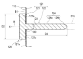
- FIG. 1 is a perspective view showing a medical device 100 according to the first embodiment.
- FIG. 2 is an enlarged cross-sectional view showing a part of a cross section taken along line 2-2 of FIG.
- FIG. 3 is an axial cross-sectional view showing the pancreatic duct cap 120 of the medical device 100 shown in FIG.
- the medical device 100 according to the first embodiment is applied to a procedure for joining the pancreatic parenchyma B1 and the jejunum B2 as shown in FIGS. 10 to 17.
- the medical device 100 is placed between the pancreatic parenchyma B1 and the jejunum B2 (corresponding to a pair of biological organs) to promote fusion between the pancreatic parenchyma B1 and the jejunum B2.
- the pancreatic duct cap 120 (corresponding to one biological organ) covering the opening of the promotion sheet 110 and the pancreatic duct B1b (corresponding to the living organ) and fixing the fusion promoting sheet 110 to the pancreatic parenchyma B1 (Equivalent to a cap) and.
- the medical device 100 may further include an intrusion prevention member 130 that prevents the pancreatic duct cap 120 from entering the patient's body when it falls off the pancreatic duct B1b.
- an intrusion prevention member 130 that prevents the pancreatic duct cap 120 from entering the patient's body when it falls off the pancreatic duct B1b.
- the fusion promoting sheet 110 is formed of a biodegradable sheet having a plurality of through holes 112, and has a main body portion 111 that promotes fusion of living tissues.
- the through holes 112 formed in the main body 111 are regularly and periodically provided in the plane direction of the main body 111. However, each through hole 112 may be randomly provided in each portion of the main body portion 111 in the surface direction.
- each through hole 112 extends substantially vertically between the front surface 113 and the back surface 114 along the thickness direction of the main body 111 (vertical direction in FIG. 2).
- each through hole 112 may be bent or curved in a zigzag shape between the front surface 113 and the back surface 114 in the cross section along the thickness direction of the main body portion 111.
- Each through hole 112 has a substantially circular planar shape (the shape when the front surface 113 of the main body 111 or the back surface 114 of the main body 111 is viewed in a plan view).
- the planar shape of each through hole 112 is not particularly limited, and may be, for example, an ellipse or a polygon (rectangle, triangle, etc.). Further, the plane shape and the cross-sectional shape may be different for each through hole 112.
- the main body 111 has a substantially circular planar shape.
- the planar shape of the main body 111 is not particularly limited, and may be, for example, an ellipse or a polygon (rectangle, triangle, etc.).
- the thickness of the main body 111 is not particularly limited, but is preferably 0.05 to 0.3 mm, more preferably 0.1 to 0.2 mm.
- the strength is such that the main body 111 is not damaged when the fusion promoting sheet 110 is handled.
- the thickness of the main body 111 is 0.3 mm or less (particularly 0.2 mm or less)
- the main body 111 adheres to the biological tissue to which the main body 111 is applied and follows the biological tissue. It can be provided with sufficient flexibility.
- the main body 111 is a value of the ratio of the hole diameter D1 (distance D1 shown in FIG. 2) of the through hole 112 to the pitch P of the through hole 112 (distance P shown in FIG. 2 and the distance between adjacent through holes 112). However, it is preferably 0.25 or more and less than 40. When the planar shape of the through hole 112 is a perfect circle, the hole diameter D1 of the through hole 112 is equal to the diameter of the perfect circle.
- the diameter of a perfect circle having the same area as the area of the opening of the through hole 112 (the portion of the through hole 112 facing the front surface 113 or the back surface 114) ( The equivalent circle diameter) can be the hole diameter D1 of the through hole 112.
- the main body 111 has a plurality of through holes 112, there are a plurality of values of the hole diameter D1 corresponding to each through hole 112. Therefore, in the present embodiment, in calculating the above-mentioned ratio value, the arithmetic mean value of two or more points of the hole diameter D1 corresponding to each of the plurality of through holes 112 is used as the representative value of the hole diameter D1. ..
- the pitch P of the plurality of through holes 112 is defined by the shortest distance between the openings of the two through holes 112. However, as for the value of the pitch P, there are a plurality of values of the pitch P corresponding to the combination of the adjacent through holes 112. Therefore, in the present embodiment, in calculating the above-mentioned ratio value, the arithmetic mean value of two or more points of the pitch P values corresponding to the combinations of the adjacent through holes 112 is used as the representative value of the pitch P. And.
- the pitch P, the hole diameter D1, the ratio of the hole diameter D1 to the pitch P, and the like of the through hole 112 are examples, and are not limited thereto.
- the main body 111 can be made of a biodegradable material.
- the constituent material of the main body 111 is not particularly limited, and examples thereof include biodegradable resins.
- biodegradable resin for example, those described in Japanese Patent Publication No. 2011-528275, Japanese Patent Publication No. 2008-514719, International Publication No. 2008-1952, Japanese Patent Publication No. 2004-509205 and the like are known.
- Biodegradable (co) polymers can be used. Specifically, it is selected from the group consisting of (1) aliphatic polyester, polyester, polyacid anhydride, polyorthoester, polycarbonate, polyphosphazene, polyphosphate ester, polyvinyl alcohol, polypeptide, polysaccharide, protein, and cellulose.
- the biodegradable sheet is selected from the group consisting of aliphatic polyesters, polyesters, polyacid anhydrides, polyorthoesters, polycarbonates, polyphosphazenes, polyphosphates, polyvinyl alcohols, polypeptides, polysaccharides, proteins, and celluloses. It preferably contains at least one biodegradable resin selected from the group consisting of a polymer and a copolymer composed of one or more monomers constituting the polymer.
- the manufacturing method of the main body 111 is not particularly limited, and examples thereof include a method of manufacturing a fiber made of the above-mentioned biodegradable resin and manufacturing a mesh-shaped sheet using the fiber.
- the method for producing the fiber made of a biodegradable resin is not particularly limited, and examples thereof include an electrospinning method (electrospinning method / electrostatic spinning method) and a melt blow method. As the main body 111, only one of the above methods may be selected and used, or two or more of the above methods may be selected and appropriately combined.
- the biodegradable sheet according to the present invention is obtained by spinning the fibers made of the biodegradable resin described above according to a conventional method and knitting the obtained fibers into a mesh shape. May be manufactured.
- the main body 111 induces a biological reaction by a constituent material such as a biodegradable resin constituting the main body 111.
- the main body 111 induces the expression of biological components such as fibrin by this action.
- the biological components induced in this way can promote fusion by accumulating so as to penetrate through the through hole 112 of the main body 111. Therefore, by arranging the main body 111 of the fusion promoting sheet 110 between the pancreatic parenchyma B1 and the jejunum B2, fusion is promoted by the above mechanism.
- the material of the fusion promoting sheet 110 does not have to be biodegradable as long as it can promote the fusion of biological organs. Further, the fusion promoting sheet 110 may not have a through hole 112 formed regardless of the material, as long as it is possible to promote the fusion of living organs.
- pancreatic duct cap 120 As shown in FIGS. 1 and 3, the pancreatic duct cap 120 is connected to a cover portion 121 that covers the opening of the pancreatic duct B1b and a fusion promoting sheet 110 that can be fixed to the pancreatic parenchyma B1.
- a unit 122 is provided.
- the fixation portion 122 in the present embodiment, has an insertion portion 124 that is inserted into the pancreatic duct B1b.
- the pancreatic duct cap 120 in the state where the pancreatic duct cap 120 is attached to the pancreatic parenchyma B1, the side on which the pancreatic parenchyma B1 is arranged is referred to as the "tip side", and the opposite side is referred to as the "base end side”. Further, the direction from the tip end side to the base end side (or the opposite direction) is referred to as an axial direction X, and the direction intersecting the axial direction X is referred to as a radial direction R. In this embodiment, the axial direction X coincides with the extending direction (longitudinal direction) of the insertion portion 124.
- a constant range from the tip (tip end) in the axial direction X is referred to as a tip portion, and a constant range from the proximal end (most proximal end) in the axial direction X is referred to as a proximal end portion.
- the cover portion 121 has a plate-like outer shape in the present embodiment.
- the outer shape of the cover portion 121 in a plan view from the axial direction X is circular.
- the specific shape of the cover portion 121 is not particularly limited as long as it can cover the opening of the pancreatic duct B1b.
- the cover portion 121 may have an elliptical shape or a polygonal outer shape in a plan view from the axial direction X.
- the maximum dimension D2 (diameter D2 in the present embodiment) of the cover portion 121 in the radial direction R is the maximum dimension D3 (diameter in the present embodiment) of the insertion portion 124 in the radial direction R in the present embodiment. It is larger than D3). Therefore, the cover portion 121 can sufficiently cover the opening of the pancreatic duct B1b and prevent the pancreatic duct cap 120 from entering the pancreatic duct B1b.
- the maximum dimension D2 in the radial direction R of the cover portion 121 is not particularly limited, but can be, for example, 1 mm to 50 mm.
- the cover portion 121 is provided with a holding portion 123 that holds one end of the intrusion prevention member 130.
- the holding portion 123 is composed of an insertion portion through which one end of the intrusion prevention member 130 is inserted.
- the configuration of the holding portion 123 is not particularly limited as long as one end of the intrusion prevention member 130 can be held.
- the holding portion 123 may be composed of one end of the intrusion prevention member 130 and an adhesive portion adhered to the cover portion 121.
- the holding portion 123 is arranged on the base end surface 121a of the cover portion 121 in FIG. 1, the position where the holding portion 123 is provided is not particularly limited.
- a non-slip portion (not shown) may be formed to suppress the above.
- the non-slip portion is not particularly limited, but can be composed of, for example, a plurality of groove portions, a plurality of uneven portions, an adhesive layer, and a combination thereof formed on the peripheral surface 121b of the cover portion 121. According to such a configuration, the operator can easily remove the pancreatic duct cap 120 from the pancreatic duct B1b by grasping the peripheral surface 121b of the cover portion 121 with his / her fingers.
- the insertion portion 124 has a long outer shape extending in the axial direction X.
- the tip portion of the insertion portion 124 forms a hole 140 in the fusion promoting sheet 110 by being pressed against the fusion promoting sheet 110.
- the insertion portion 124 is inserted into the pancreatic duct B1b with the hole 140 of the fusion promoting sheet 110 inserted.
- the insertion portion 124 fixes the fusion promoting sheet 110 to the pancreatic parenchyma B1.
- the hole 140 may not be formed by pressing the tip of the insertion portion 124 against the fusion promoting sheet 110, but may be formed in advance on the fusion promoting sheet 110 in a state before use.
- the insertion portion 124 is connected to the central portion in the surface direction of the tip surface 121c (the surface facing the fusion promoting sheet 110) of the cover portion 121.
- the tip of the insertion portion 124 has a tapered shape that tapers from the proximal end side toward the distal end side. Therefore, the operator can easily insert the insertion portion 124 into the pancreatic duct B1b.
- the insertion portion 124 is arranged on the outer diameter constant portion 124a having a substantially constant outer diameter from the tip end side to the proximal end side and on the tip end side of the outer diameter constant portion 124a. It has a tapered portion 124b that is tapered from the proximal end side toward the distal end side.
- the insertion portion 124 may be formed only by the tapered portion from the tip end (tip end) to the base end (most base end). Further, the insertion portion 124 may be formed only by a portion having a substantially constant outer diameter from the tip end (tip end) to the proximal end (most proximal end).
- the maximum dimension D3 (diameter in this embodiment) along the radiation direction R of the insertion portion 124 is not particularly limited as long as it can be inserted into the pancreatic duct B1b, but can be, for example, 1 mm to 5 mm.
- the dimension D4 along the axial direction X of the insertion portion 124 is not particularly limited, but can be, for example, 30 mm to 50 mm.
- the insertion portion 124 is preferably made of a flexible material.
- a material is not particularly limited, and is, for example, a polyolefin or poly composed of polyethylene, polypropylene, polybutene, an ethylene-propylene copolymer, an ethylene-vinyl acetate copolymer, an ionomer, or a mixture of two or more thereof.
- polymer materials such as vinyl chloride, polyamide, polyamide elastomer, polyester, polyester elastomer, polyurethane, polyurethane elastomer, polyimide, and fluororesin, or a mixture thereof, or the above two or more kinds of polymer materials.
- the pancreatic duct cap 120 is a pancreas when the operator inserts a suture member for suturing the pancreatic parenchyma B1 and the jejunum B2 into the pancreatic parenchyma B1 and the jejunum B2 in the procedure of joining the pancreatic parenchyma B1 and the jejunum B2. It is practically attached to B1. Since the pancreatic duct cap 120 does not hang down from the pancreatic duct B1b unlike the conventional pancreatic duct tube, it is unlikely to interfere with the procedure for the operator to insert the suture member into the pancreatic parenchyma B1 and the jejunum B2.
- the operator can easily perform a procedure of inserting the suture member into the pancreatic parenchyma B1 and the jejunum B2 while suppressing the leakage of pancreatic juice (corresponding to body fluid) from the pancreatic duct B1b. it can.
- the fusion promoting sheet 110 is formed with a plurality of through holes 112, the fusion promoting sheet 110 is very soft. Therefore, the union promotion sheet 110 is liable to be twisted or misaligned.
- the fusion promoting sheet 110 is fixed with a biodegradable suture (absorbent thread), staples, or the like. It can be fixed to the pancreatic parenchyma by the member.
- the pancreatic duct cap 120 has the pancreatic duct B1b and the jejunum B2 similar to the conventional pancreatic duct tube after the suture member for suturing the pancreatic parenchyma B1 and the jejunum B2 is inserted into the pancreatic parenchyma B1 and the jejunum B2.
- the suture member is removed from the pancreatic parenchyma B1 so as not to interfere with the procedure of inserting the suture member into the pancreatic duct B1b.
- the pancreatic duct cap 120 according to the present embodiment is configured as an instrument temporarily attached to the pancreatic parenchyma B1 during the procedure.
- pancreatic fluid from the pancreatic duct B1b is applied to the junction between the pancreatic parenchyma B1 and the jejunum B2 using a known device such as a pancreatic duct tube.
- a drainage route may be formed to drain the pancreatic fluid from the pancreatic duct B1b to the outside of the junction so as not to leak.
- the intrusion prevention member 130 is formed of a long member having flexibility such as a thread or a string.
- the intrusion prevention member 130 can prevent the pancreatic duct cap 120 from entering the patient's body when the pancreatic duct cap 120 falls off from the pancreatic duct B1b.
- the other end of the intrusion prevention member 130 may be connected to a living body such as the pancreatic parenchyma B1.
- a needle portion (not shown) is provided at the other end of a long member constituting the intrusion prevention member 130, and the needle portion is hooked on a living body such as the pancreatic parenchyma B1, so that the other end of the intrusion prevention member 130 is pancreatic. It may be substantially connected to B1.
- the medical device 100 has a fusion promoting sheet 110 and a pancreatic duct cap 120.
- the fusion promoting sheet 110 promotes fusion between the pancreatic parenchyma B1 and the jejunum B2 by being arranged between the pancreatic parenchyma B1 and the jejunum B2.
- the pancreatic duct cap 120 includes a cover portion 121 that covers the opening of the pancreatic duct B1b and a fixing portion 122 that is connected to the cover portion 121 and can fix the fusion promoting sheet 110 to the pancreatic parenchyma B1.
- the fusion promoting sheet 110 can be sandwiched between the joined sites of the pancreatic parenchyma B1 and the jejunum B2 to promote the fusion of the biological tissues of the pancreatic parenchyma B1 and the jejunum B2. Further, the fusion promoting sheet 110 can be fixed to the pancreatic parenchyma B1 by the fixing member while the fusion promoting sheet 110 is fixed to the pancreatic parenchyma B1 by the pancreatic duct cap 120. Therefore, it is possible to prevent the fusion promoting sheet 110 from being displaced from the pancreatic parenchyma B1 or being twisted and deformed.
- pancreatic duct cap 120 can suppress the leakage of pancreatic juice from the pancreatic duct B1b by covering the opening of the pancreatic duct B1b during the procedure, and does not hang down from the pancreatic duct B1b unlike the conventional pancreatic duct tube, which hinders the procedure. hard.
- the medical device 100 in the procedure of joining the pancreatic parenchyma B1 and the jejunum B2, the risk of postoperative suture failure can be reduced, and the leakage of pancreatic juice from the pancreatic duct B1b during the procedure can be suppressed.
- the pancreatic parenchyma B1 and the jejunum B2 can be easily joined.
- the fixing portion 122 includes an insertion portion 124 to be inserted into the pancreatic duct B1b.
- the insertion portion 124 can fix the fusion promoting sheet 110 to the pancreatic parenchyma B1 by being inserted into the pancreatic duct B1b with the fusion promoting sheet 110 inserted. Further, since the insertion portion 124 is inserted into the pancreatic duct B1b, leakage of pancreatic juice from the pancreatic duct B1b can be effectively suppressed.
- At least the tip portion of the insertion portion 124 has a tapered shape that tapers from the proximal end side toward the distal end side. Therefore, the operator can easily insert the insertion portion 124 into the pancreatic duct B1b.
- the medical device 100 is formed of a long member having flexibility, one end of which is connected to the pancreatic duct cap 120, and the other end of which is connected to the fusion promoting sheet 110 or at least one of the living body 130. Further have. Therefore, the medical device 100 can effectively prevent the pancreatic duct cap 120 from entering the patient's body.
- FIG. 4A is an axial sectional view showing a modification 1 of the pancreatic duct cap 120 according to the first embodiment
- FIG. 4B is an axial sectional view showing a modification 2 of the pancreatic duct cap 120 according to the first embodiment.
- the fixing portion 122 constituting the pancreatic duct cap 120 may further have a movement suppressing portion 125 capable of suppressing the movement of the insertion portion 124 in the pancreatic duct B1b.
- the movement suppressing portion 125 is arranged between the tip end (tip end) and the proximal end (most proximal end) of the insertion portion 124 and intersects the longitudinal direction (axial direction X) of the insertion portion 124.
- the expansion portion 126a that can expand and contract in the radial direction R may be used.
- the expansion portion 126a forms an internal space 126b into which the fluid is injected between the expansion portion 126a and the insertion portion 124.
- a communication passage 126c is formed in the cover portion 121 and the insertion portion 124.
- the cover portion 121 is provided with an opening 126d that communicates with the communication passage 126c and into which a fluid injection device (not shown) such as a syringe is inserted, and a valve body 126e that covers the opening 126d.
- a fluid injection device such as a syringe is inserted into the opening 126d with the insertion portion 124 inserted into the pancreatic duct B1b, and the fluid is injected into the internal space 126b by the injection device.
- the expansion portion 126a expands outward in the radial direction R and is pressed against the inner wall of the pancreatic duct B1b. Therefore, the expansion portion 126a can effectively suppress the movement of the insertion portion 124 in the pancreatic duct B1b.
- the valve body 126e closes the opening 126d airtightly or liquidtightly. Therefore, the expansion unit 126a can maintain the expanded state.
- a fluid injection device such as a syringe is inserted into the opening 126d again, and the fluid is discharged from the internal space 126b by the injection device.
- the expansion portion 126a contracts inward in the radial direction R. Therefore, the user can easily remove the insertion portion 124 from the pancreatic duct B1b.
- the movement suppressing unit 125 may be an adsorption unit 127a that can be adsorbed on the inner wall of the pancreatic duct B1b.
- the suction portion 127a can be composed of, for example, a plurality of suction holes 127b that open on the peripheral surface of the insertion portion 124.
- the cover portion 121 and the insertion portion 124 are formed with a communication passage 127c communicating with the suction hole 127b.
- the cover portion 121 is provided with an opening 127d, which communicates with the communication passage 127c and into which a suction device (not shown) such as a syringe is inserted, and a valve body 127e, which covers the opening 127d.
- a suction device such as a syringe is inserted into the opening 127d to perform suction.
- the adsorption portion 127a is adsorbed on the inner wall of the pancreatic duct B1b.
- the valve body 127e closes the opening 127d airtightly or liquidtightly. Therefore, the adsorption portion 127a can effectively suppress the movement of the insertion portion 124 in the pancreatic duct B1b.
- the configuration of the expansion portion 126a and the suction portion 127a is not limited to the above.
- the injection of a fluid into the internal space 126b of the expansion portion 126a is not an injection device such as a syringe, but a bag-shaped injection member or the like which is connected to the opening 126d and injects the fluid into the internal space 126b by being crushed. It may be configured by.
- the fixing portion 122 may further have a movement suppressing portion 125 that suppresses the movement of the insertion portion 124 in the pancreatic duct B1b. Therefore, the movement suppressing portion 125 can effectively prevent the insertion portion 124 from falling out of the pancreatic duct B1b.
- the movement suppressing portion 125 may be an expansion portion 126a that can expand and contract in the radial direction R that intersects the axial direction X of the insertion portion 124 between the tip end and the base end of the insertion portion 124.
- the dilation portion 126a expands outward in the radial direction R and is pressed against the inner wall of the pancreatic duct B1b. Therefore, the expansion portion 126a can effectively prevent the insertion portion 124 from falling out of the pancreatic duct B1b. Further, by pressing the dilation portion 126a against the inner wall of the pancreatic duct B1b, it is possible to effectively prevent pancreatic juice from leaking from the pancreatic duct B1b.
- the movement suppressing unit 125 may be an adsorption unit 127a capable of adsorbing to the inner wall of the pancreatic duct B1b.
- the adsorption portion 127a adsorbs to the inner wall of the pancreatic duct B1b. Therefore, the adsorption portion 127a can effectively prevent the insertion portion 124 from falling off from the pancreatic duct B1b.
- 5A and 5B are axial cross-sectional views showing a modification 3 of the pancreatic duct cap 120 according to the first embodiment.
- the fixing portion 122 constituting the pancreatic duct cap 120 may further have a removal assisting portion 128 that assists in removing the insertion portion 124 from the pancreatic duct B1b.
- the removal assisting portion 128 is provided at least at the base end portion of the insertion portion 124, and is contracted inward in the radial direction R intersecting the axial direction X of the insertion portion 124, and is in the radial direction R. It is composed of an expansion unit 128a that can shift to an expanded state that is expanded outward. As shown in FIG. 5B, the expansion portion 128a has an outer shape that tapers from the proximal end side toward the distal end side in the expanded state.
- the expansion portion 128a forms an internal space 128b into which a fluid is injected between the tip end surface 121c of the cover portion 121 and the base end portion of the insertion portion 124.
- the cover portion 121 and the insertion portion 124 are formed with a communication passage 128c communicating with the internal space 128b.
- the cover portion 121 is provided with an opening 128d that communicates with the communication passage 128c and into which a fluid injection device (not shown) such as a syringe is inserted, and a valve body 128e that covers the opening 128d.
- the expansion portion 128a expands outward in the radial direction R as shown in FIG. 5B.
- the expansion portion 128a is provided at the base end portion of the insertion portion 124, and has an outer shape that tapers from the base end side toward the tip end side in the expanded state. Therefore, the expanded dilated portion 128a presses the pancreatic duct B1b so that the cover portion 121 is separated from the pancreatic parenchyma B1. Therefore, the operator can easily remove the pancreatic duct cap 120 from the pancreatic duct B1b.
- FIG. 6 is an axial sectional view showing a modified example 4 of the pancreatic duct cap 120 according to the first embodiment.
- the insertion portion 124 constituting the pancreatic duct cap 120 may be provided with an absorbing member 129 that absorbs body fluid such as pancreatic juice.
- the absorbing member 129 is made of a porous material such as a sponge, and absorbs body fluid such as pancreatic juice in a state where the insertion portion 124 is inserted into the pancreatic duct B1b. Therefore, the absorbing member 129 can effectively prevent body fluid such as pancreatic juice from leaking from the pancreatic duct B1b.
- a hole portion 124c extending in the longitudinal direction (axial direction X) of the insertion portion 124 is formed at the tip end portion of the insertion portion 124, and the absorbing member 129 is arranged in the hole portion 124c. Therefore, the operator can easily insert the insertion portion 124 into the pancreatic duct B1b.
- the absorbing member 129 may be provided on the outer surface of the insertion portion 124.
- the insertion portion 124 may be provided with an absorbing member 129 capable of absorbing body fluids. With such a configuration, it is possible to effectively suppress the leakage of pancreatic juice from the pancreatic duct B1b.
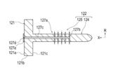
- FIG. 7 is a perspective view showing a modified example 5 of the pancreatic duct cap 120 according to the first embodiment.
- the fixing portion 122 constituting the pancreatic duct cap 120 may be formed not by the insertion portion 124 but by a plurality of needle portions 224 provided on the tip surface 121c of the cover portion 121. ..
- the plurality of needle portions 224 are provided on the distal end surface 121c of the cover portion 121 on the outer side of the radial direction R with respect to the region A covering the opening of the pancreatic duct B1b.
- the plurality of needles 224 are punctured into the pancreatic parenchyma B1 through the fusion promoting sheet 110.
- the plurality of needles 224 fix the fusion promoting sheet to the pancreatic parenchyma B1.
- the plurality of needle portions 224 are provided at substantially equal intervals in the circumferential direction around the axial direction X.
- the number and position of the needle portions 244 are not particularly limited.
- the fixing portion 122 may include both the insertion portion 124 and the plurality of needle portions 224.
- FIG. 8 is a perspective view showing a modification 6 of the pancreatic duct cap 120 according to the first embodiment.
- the pancreatic duct cap 120 may further have a frame portion 225 that is connected to the cover portion 121, extends in the radial direction R, and holds the fusion promoting sheet 110 removably.
- the frame portion 225 is composed of a plurality of rod-shaped members 226.
- Each rod-shaped member 226 extends from the cover portion 121 toward the outside in the radial direction R.
- the end portion 226b on the outer side of the radial direction R of each rod-shaped member 226 is located closer to the base end side than the end portion 226a on the inner side of the radial direction R of each rod-shaped member 226. It is curved. Therefore, when the fusion promoting sheet 110 is arranged on the pancreatic parenchyma B1, the fusion promoting sheet 110 is sequentially arranged from the central portion of the radiation direction R of the fusion promotion sheet 110 toward the outer side portion of the radiation direction R. It attaches to pancreatic parenchyma B1. As a result, it is possible to effectively suppress the twisting and misalignment of the fusion promoting sheet 110.
- FIG. 9 is a flowchart showing each procedure of a treatment method for joining the pancreatic parenchyma and the jejunum using a medical device.
- the treatment method is to use a fusion promoting sheet that promotes the fusion of living tissue formed from a biodegradable sheet having multiple through holes, and a cover portion that covers the opening of the pancreatic duct and a fusion promoting sheet that is connected to the cover portion. It comprises preparing a medical device having a pancreatic duct cap having a fixation portion that can be fixed to the pancreatic parenchyma (S101). The treatment method further comprises arranging the medical device so that the cover covers the opening of the pancreatic duct and the fixation part fixes the fusion promotion sheet to the pancreatic parenchyma (S102), and the fusion promotion sheet is fixed to the pancreas with a fixing member. It includes fixing to the substance (S103).
- the treatment method further includes forming a drainage route for draining pancreatic juice from the pancreatic duct to the outside of the junction so that the pancreatic juice in the pancreatic duct does not leak to the junction between the pancreatic parenchyma and the jejunum (S104).
- the treatment method further involves sandwiching at least a part of the fusion promoting sheet between the pancreatic parenchyma and the jejunum (S105), and joining with at least a part of the fusion promoting sheet sandwiched between the pancreatic parenchyma and the jejunum. This includes placing a fusion-promoting sheet between the pancreatic parenchyma and the jejunum (S107).
- any medical device can be selected from the above-mentioned medical devices, and other medical devices can also be selected.
- a usage example of a specific medical device will be described as a typical example that can be suitably used for each procedure.
- detailed description of known procedure procedures, known medical devices, medical instruments, etc. will be omitted as appropriate.
- arranging the fusion promoting sheet between the pancreatic parenchyma and the jejunum means that the fusion promoting sheet is placed in direct or indirect contact with the pancreatic parenchyma or the jejunum.
- the fusion-promoting sheet is placed with a spatial gap formed between the pancreatic parenchyma and the jejunum, or the fusion-promoting sheet is placed in both states (eg, pancreatic parenchyma and jejunum). It means at least one of (the fusion promoting sheet is in contact with one biological organ and the fusion promoting sheet is not in contact with the other biological organ).
- peripheral does not define a strict range (region), but a predetermined range (region) as long as the purpose of treatment (joining of pancreatic parenchyma and jejunum) can be achieved. ) Means.
- order of the procedure procedures described in each treatment method can be changed as appropriate as long as the purpose of the treatment can be achieved.
- relatively approaching means both bringing two or more objects to be approached close to each other and bringing only one close to the other.
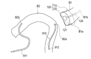
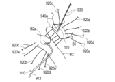
- FIGS. 10 to 17 are diagrams for explaining pancreatic parenchymal-jejunal anastomosis.
- a plurality of both end needles 920a to 920e which will be described later, are omitted.
- an example of the treatment method will be described with reference to FIGS. 10 to 17.
- an example of using the medical device 100 shown in FIG. 1 will be described.
- the surgeon prepares a medical device 100 having a fusion promoting sheet 110 and a pancreatic duct cap 120.
- the surgeon has a medical device such that the cover portion 121 covers the opening of the pancreatic duct B1b and the fixation portion 122 (insertion portion 124) fixes the fusion promoting sheet 110 to the pancreatic parenchyma B1.
- 100 is placed on the cut surface B1a of the pancreatic parenchyma B1.
- the specific procedure for arranging the medical device 100 on the cut surface B1a of the pancreatic parenchyma B1 is not particularly limited, but for example, the following procedure can be performed.
- the operator attaches the fusion promoting sheet 110 to the cut surface B1a.
- the operator inserts the insertion portion 124 into the pancreatic duct B1b while forming a hole 140 in the fusion promotion sheet 110 by pressing the tip of the insertion portion 124 of the pancreatic duct cap 120 against the fusion promotion sheet 110.
- pancreatic duct cap 120 causes pancreatic juice to leak from the pancreatic duct B1b when the operator inserts a suture member (both ends needles 920a to 920e) for suturing the pancreatic parenchyma B1 and the jejunum B2 into the pancreatic parenchyma B1 and the jejunum B2. Suppress that.
- the pancreatic duct tube 910 may be inserted into the jejunum B2.
- a known resin tube having a bump (convex portion) formed at the end portion 912 to prevent removal can be used.
- the operator may use another device such as the pancreatic duct tube 910 instead of the pancreatic duct cap 120 when forming the hole 140 through which the pancreatic duct cap 120 is inserted.
- the hole 140 through which the pancreatic duct cap 120 is inserted may be formed in advance in the fusion promoting sheet 110 in a state before use. Further, the operator may insert the insertion portion 124 into the pancreatic duct B1b after inserting the insertion portion 124 into the hole portion 140 of the fusion promoting sheet 110.
- the operator fixes the fusion promoting sheet 110 to the pancreatic parenchyma B1 with a fixing member.
- a procedure for fixing the fusion promoting sheet 110 to the pancreatic parenchyma B1 by using a plurality of both end needles 920a to 920e as fixing members will be described.
- known needles having a bioabsorbable absorbent thread (suture) and a biocompatible needle portion attached to both ends of the absorbent thread can be used.
- the needles 930 and 940a to 940e at both ends which will be described later, are also configured to include an absorbent thread and a needle portion.
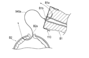
- the surgeon starts with the posterior wall B1c of the pancreatic parenchyma B1 (the dorsal portion of the pancreatic parenchyma B1 in the circumferential direction) and the portion arranged on the posterior wall B1c in the fusion promoting sheet 110.
- Both ends needles 920a are moved toward the anterior wall B1d of the pancreatic parenchyma B1 (the ventral portion of the pancreatic parenchyma B1 in the circumferential direction) and the portion of the fusion promoting sheet 110 arranged on the anterior wall B1d.
- the operator moves both ends of the needle 920a so as to insert the jejunal serosal muscular layer at the planned anastomosis site of the jejunum B2 (around the through hole B2a).
- the operator repeats such an operation, and inserts a plurality of both end needles 920a to 920e into the jejunal serosal muscular layer of the fusion promoting sheet 110, the pancreatic parenchyma B1, and the jejunum B2 as shown in FIG.
- the operator can fix the fusion promoting sheet 110 to the pancreatic parenchyma B1 by using a plurality of both end needles 920a to 920e that suture the pancreatic parenchyma B1 and the jejunum B2.
- the operator can fix the fusion promoting sheet 110 to the pancreatic parenchyma B1 using the needles 920a to 920e at both ends in a state where the fusion promoting sheet 110 is fixed to the pancreatic parenchyma B1 by the pancreatic duct cap 120. Therefore, when the operator fixes the fusion promoting sheet 110 to the pancreatic parenchyma B1 using the needles 920a to 920e at both ends, it is possible to prevent the fusion promoting sheet 110 from being displaced from the pancreatic parenchyma B1 or being twisted and deformed.
- the number of both-end needles to be inserted into the jejunal serosal muscular layer of the pancreatic parenchyma B1 and the jejunum B2 and the position to insert the both-end needles are not particularly limited. Further, the operator may fix the fusion promoting sheet 110 to the pancreatic parenchyma B1 by using biodegradable staples or the like as a fixing member instead of the plurality of needles 920a to 920e at both ends.
- the operator passes the needles 930 at both ends from the lumen side of the pancreatic duct B1b toward the anterior wall B1d side of the cut surface B1a of the pancreatic parenchyma B1.
- the needles 930 at both ends are held by a gripping instrument such as tweezers (not shown) so as not to interfere with the procedure in a state where the jejunum B2 is not inserted.
- the operator moves one end of the needles 940a at both ends from the lumen side of the pancreatic duct B1b toward the cut surface B1a of the pancreatic parenchyma B1.
- the operator inserts the other end of the needles 940a at both ends into the through hole B2a of the jejunum B2, and the needles 940a at both ends toward the outside of the jejunum B2 from the inside of the jejunum B2. Move the other end.
- the operator inserts a plurality of both-end needles 940a to 940e into different sites in the circumferential direction of the pancreatic duct B1b and the jejunum B2.
- the operator brings the posterior wall B1c of the pancreatic parenchyma B1 and the pancreatic duct B1b into close contact with the planned anastomosis site of the jejunum B2. Then, of the plurality of needles 940a to 940e at both ends, the needles 940c to 940e at both ends that insert the dorsal side (rear wall B1c side) of the pancreatic duct B1b in the circumferential direction are ligated.
- the operator inserts the end 912 of the pancreatic duct tube 910 into the pancreatic duct B1b, as shown in FIG. As a result, a drainage route is formed for discharging the pancreatic juice from the pancreatic duct B1b to the outside of the junction so that the pancreatic juice from the pancreatic duct B1b does not leak to the junction between the pancreatic parenchyma B1 and the jejunum B2.
- the operator inserts the needle portion 931 extending from the inside of the pancreatic duct B1b with the needles 930 at both ends into the through hole B2a formed in the jejunum B2, and inserts the needle portion 931 from the inside of the jejunum B2 toward the outside of the jejunum B2. Move the hands.
- the operator ligates the needles 930, 940a, and 940b at both ends (not shown).
- the number of both-end needles to be inserted into the pancreatic duct B1b and the jejunum B2 and the position to insert the both-end needles are not particularly limited.
- the operator ligates the needles 920a to 920e at both ends while pressing the jejunum B2 against the pancreatic parenchyma B1 with the operator's finger.
- the pancreatic parenchyma B1 and the jejunum B2 are sutured with the fusion promoting sheet 110 sandwiched between them.
- the jejunum B2 is deformed by the tension generated at the time of suturing so as to wrap the cut surface B1a of the pancreatic parenchyma B1 and the main body 111 of the fusion promoting sheet 110.
- the operator places the fusion promoting sheet 110 in a state where the main body 111 of the medical device 100 is sandwiched between the cut surface B1a of the pancreatic parenchyma B1 and the intestinal wall of the jejunum B2.
- the operator places the pancreatic duct tube 910 so that the end portion 911 of the pancreatic duct tube 910 is led out of the body. That is, the pancreatic duct tube 910 functions as a so-called external fistula tube.
- the main body 111 of the fusion promoting sheet 110 is placed between the cut surface B1a of the pancreatic parenchyma B1 and the intestinal wall of the jejunum B2 while being in contact with the cut surface B1a of the pancreatic parenchyma B1 and the intestinal wall of the jejunum B2. This promotes the fusion of the biological tissue of the pancreatic parenchyma B1 and the biological tissue of the intestinal wall of the jejunum B2.
- the treatment method according to the present embodiment is applied to the procedure for joining the pancreatic parenchyma B1 and the jejunum B2. Further, in the above treatment method, the periphery of the cut surface B1a of the cut pancreatic parenchyma B1 and the intestinal wall (jejunal serosal muscular layer) of the jejunum B2 are joined. According to this treatment method, the biological tissue of the pancreatic parenchyma B1 and the biological tissue of the intestinal wall of the jejunum B2 are formed by the main body 111 of the fusion promoting sheet 110 sandwiched between the cut surface B1a of the pancreatic parenchyma B1 and the intestinal wall of the jejunum B2. Can promote fusion and reduce the risk of suture failure after pancreatic parenchymal-jejunostomy.
- the operator cuts the medical device 100 of the pancreatic parenchyma B1 so that the cover portion 121 covers the opening of the pancreatic duct B1b and the fixing portion 122 fixes the fusion promoting sheet 110 to the pancreatic parenchyma B1. It is arranged on the surface B1a. Then, the operator fixes the fusion promoting sheet 110 to the pancreatic parenchyma B1 using fixing members (both ends needles 920a to 920e). Therefore, the fusion promoting sheet 110 can be fixed to the pancreatic parenchyma B1 by the fixing member while the fusion promoting sheet 110 is fixed to the pancreatic parenchyma B1 by the pancreatic duct cap 120.
- the pancreatic duct cap 120 covers the opening of the pancreatic duct B1b when the fusion promoting sheet 110 is fixed to the pancreatic parenchyma B1 with a fixing member.
- the pancreatic duct cap 120 does not hang down from the pancreatic duct B1b unlike the conventional pancreatic duct tube, and is less likely to interfere with the procedure as compared with the conventional pancreatic duct tube. Therefore, according to the above-mentioned treatment method, the pancreatic parenchyma B1 and the jejunum B2 can be easily joined while suppressing the leakage of pancreatic juice during the procedure.
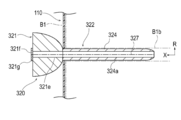
- FIG. 18 is a perspective view showing the pancreatic duct cap 320 according to the second embodiment.
- FIG. 19 is an axial sectional view showing the pancreatic duct cap 320 shown in FIG.
- the pancreatic duct cap 320 according to the first embodiment is configured so that it does not need to be removed when the suture members (both ends needles 930, 940a to 940e) are inserted into the pancreatic duct B1b. It is different from the cap 120.
- the pancreatic duct cap 320 according to the second embodiment will be described. The same configuration as that described in the medical device 100 according to the first embodiment will be omitted as appropriate.
- the pancreatic duct cap 320 includes a cover portion 321 that covers the opening of the pancreatic duct B1b, and a fixing portion 322 that is connected to the cover portion 321 and can fix the fusion promoting sheet 110 to the pancreatic parenchyma B1. , Equipped with.
- the fixation portion 322 has, in this embodiment, an insertion portion 324 that is inserted into the pancreatic duct B1b.
- the tip of the cover portion 321 has a convex shape toward the tip side. Therefore, the cover portion 321 forms a space S between the cover portion 321 and the cut surface B1a of the pancreatic parenchyma B1 in a state of being attached to the pancreatic parenchyma B1. Therefore, the operator passes the suture members (both ends needles 930, 940a to 940e) used for suturing the pancreatic duct B1b and the jejunum B2 through the space S while the cover portion 321 is fixed to the pancreatic parenchyma B1. The suture member can be inserted into the pancreatic duct B1b.
- the pancreatic duct cap 320 is used not only when the suture members (both ends needles 920a to 920e) are inserted into the pancreatic parenchyma B1 and the jejunum B2, but also when the suture members (both ends needles 930 and 940a to 940e) are inserted into the pancreatic duct B1b. Also, the leakage of pancreatic juice from the pancreatic duct B1b can be suppressed.
- the tip of the cover portion 321 may be provided with a holding portion 321a capable of holding the pancreatic duct B1b and / or the living tissue in the vicinity thereof.
- the holding portion 321a can be composed of, for example, a plurality of needle portions 321b.
- the plurality of needle portions 321b are provided at positions different from the positions through which the suture members (both ends needles 930, 940a to 940e) pass in the circumferential direction of the cover portion 321.
- the suture member is inserted into the pancreatic duct B1b
- the operator pulls the cover portion 321 toward the proximal end side, so that the holding portion 321a moves toward the proximal end side.
- the living tissue in the pancreatic duct B1b and / or its vicinity protrudes toward the proximal end side with respect to the other region of the cut surface B1a. Therefore, the operator can easily insert the end of the suture member into the lumen of the pancreatic duct B1b.
- each needle portion 321b has a linearly extending shape, but may have a hook-shaped curved shape.
- the cover portion 321 is configured to be removable from the insertion portion 324, the insertion portion 324 is formed of a biodegradable material, and the insertion portion 324 has a cavity 324a that penetrates the insertion portion 324 in the axial direction X. May be formed. According to such a configuration, after the suture member is inserted into the pancreatic duct B1b, the cover portion 321 can be removed from the insertion portion 324 and inserted into the through hole B2a of the jejunum B2 at the base end portion of the insertion portion 324.
- the insertion portion 324 is in vivo together with the fusion promoting sheet 110 in a state where the tip end portion of the insertion portion 324 is inserted into the pancreatic duct B1b and the base end portion of the insertion portion 324 is inserted into the through hole B2a of the jejunum B2. Detained in.
- the indwelling insertion portion 324 discharges the pancreatic juice from the pancreatic duct B1b into the jejunum B2 so that the pancreatic juice from the pancreatic duct B1b does not leak to the junction between the pancreatic parenchyma B1 and the jejunum B2.
- the pancreatic duct cap 320 may be configured such that the insertion portion 324 functions as a so-called internal fistula tube.
- the method of configuring the insertion portion 324 to be removable from the cover portion 321 is not particularly limited, but for example, a method of forming a detachable engaging portion between the cover portion 321 and the insertion portion 324, the cover portion 321 and the insertion portion 324. Examples thereof include a method of forming a break portion capable of separating the cover portion 321 and the insertion portion 324 at the boundary portion between them.
- FIG. 19 shows a female screw portion 321c formed on the cover portion 321 and a male screw portion 324b formed on the insertion portion 324 as an example of the detachable engaging portion.
- the cover portion 321 is not configured to be removable from the insertion portion 324, and the pancreatic duct cap 320 may be removed from the pancreatic parenchyma B1 after the suture member is inserted into the pancreatic duct B1b and the jejunum B2.
- a known device such as a pancreatic duct tube may be used as the external fistula tube in the same manner as the above-mentioned treatment method.
- the cover portion 321 is formed with a space S through which the suturing member used for suturing the pancreatic duct B1b and the jejunum B2 passes. Since it is not necessary to remove the pancreatic duct cap 320 when inserting the suture member into the pancreatic duct B1b, the pancreatic duct cap 320 is used only when the suture member for suturing the pancreatic parenchyma B1 and the jejunum B2 is inserted into the pancreatic parenchyma B1 and the jejunum B2.
- pancreatic fluid from the pancreatic duct B1b can be suppressed.
- the cover portion 321 is configured to be removable from the insertion portion 324, the insertion portion 324 is formed of a biodegradable material, and the insertion portion 324 has a cavity 324a penetrating the insertion portion 324 in the axial direction X. May be formed. According to such a configuration, since the insertion portion 324 can function as an internal fistula tube, it is not necessary to use another device such as a pancreatic duct tube.
- FIG. 20 is a perspective view showing a modification 1 of the pancreatic duct cap 320 according to the second embodiment.
- the space S through which the suturing member used for suturing the pancreatic duct B1b and the jejunum B2 passes is formed over the entire circumference of the cover portion 321.
- the groove portion 321d recessed inward in the radial direction R is moved in the circumferential direction of the cover portion 321.
- a plurality may be formed.
- each groove portion 321d forms a space S through which each suture member passes
- the space S through which the suture member used for suturing the pancreatic duct B1b and the jejunum B2 passes is partially formed in the circumferential direction of the cover portion 321. ..
- eight groove portions 321d are formed in the cover portion 321 so that the eight suture members can pass through, but the number and position of the groove portions 321d are appropriately determined according to the number and position of the suture members to be passed. It can be changed.
- FIG. 21 is an axial sectional view showing a modification 2 of the pancreatic duct cap 320 according to the second embodiment.
- the fixing portion 322 may further have a movement suppressing portion 325 that suppresses the movement of the insertion portion 324 in the pancreatic duct B1b.
- the movement suppressing portion 325 is arranged between the tip end (tip end) and the base end (most base end) of the insertion portion 324, and the radial direction R intersects the axial direction X of the insertion portion 324. It may be an expansion portion 326a that can be expanded and contracted.
- the expansion portion 326a forms an internal space 326b into which the fluid is injected between the expansion portion 326a and the insertion portion 324.
- the cover portion 321 and the insertion portion 324 are formed with a communication passage 326c communicating with the internal space 326b.
- the cover portion 321 is provided with an opening 326d that communicates with the communication passage 326c and into which a fluid injection device (not shown) such as a syringe is inserted.
- the insertion portion 324 is provided with a check valve 326e that allows the inflow of fluid from the communication passage 326c into the internal space 326b but prohibits the outflow in the reverse direction.
- a fluid injection device such as a syringe is inserted into the opening 326d with the insertion portion 324 inserted into the pancreatic duct B1b, and the fluid is injected into the internal space 326b by the injection device.
- the expansion portion 326a expands outward in the radial direction R and is pressed against the inner wall of the pancreatic duct B1b. Therefore, the expansion portion 326a can effectively suppress the movement of the insertion portion 324 in the pancreatic duct B1b.
- the cover portion 321 is removed from the insertion portion 324, and the base end portion of the insertion portion 324 is inserted into the through hole B2a of the jejunum B2. Then, the insertion portion 324 is placed in the living body.
- a check valve 326e is provided in the insertion portion 324. Therefore, even when the insertion portion 324 is indwelled in the living body, the expansion portion 326a can effectively suppress the movement of the insertion portion 324 in the pancreatic duct B1b.
- the movement suppressing portion 325 may be formed not by the expansion portion 326 but by an adsorption portion that can be adsorbed on the inner wall of the pancreatic duct B1b.
- FIGS. 22A to 22C are axial sectional views showing a modification 3 of the pancreatic duct cap 320 according to the second embodiment.
- the pancreatic duct cap 320 may be configured such that the cover portion 321 and the insertion portion 324 are split in the axial direction X.
- the cover portion 321 is formed with a lumen 321e communicating with the lumen 324a of the insertion portion 324. Further, the cover portion 321 is provided with an opening 321f communicating with the lumen 321e of the cover portion 321 and a check valve 321g covering the opening 321f. As shown in FIG. 22B, the check valve 321g is configured so that the end portion 912 of the pancreatic duct tube 910 can be inserted into the lumen 321e of the cover portion 321 without tearing the cover portion 321.
- the cover portion 321 and the insertion portion 324 are formed with a fracture portion 327 which is a starting point of fracture when the cover portion 321 and the insertion portion 324 are pulled in opposite directions in the direction extending in the X-axis direction and intersecting the X-axis.
- the fractured portion 327 can be formed by, for example, a thin-walled portion or a notched portion having a wall thickness thinner than that of other regions.
- the operator After inserting the suture member into the pancreatic duct B1b, the operator performed the pancreatic duct tube 910 from the check valve 321 g of the cover portion 321 to the lumen 321e of the cover portion 321 and the lumen 324a of the insertion portion 324, as shown in FIG. 22B. Insert the end 912 of the.
- the operator tears the cover portion 321 and the insertion portion 324 in the axial direction X while maintaining the state in which the pancreatic duct tube 910 is arranged in the pancreatic duct B1b, and the pancreatic duct from the pancreatic parenchyma B1. Remove the cap 320.
- pancreatic duct tube 910 can be inserted into the pancreatic duct B1b without removing the pancreatic duct cap 320. Therefore, it is possible to effectively suppress the leakage of pancreatic juice from the pancreatic duct B1b during the procedure.
- the medical device according to the present invention has been described above through a plurality of embodiments and modifications, the present invention is not limited to each of the described configurations, and may be appropriately modified based on the description of the scope of claims. Is possible.
- the medical device according to the present invention may be applied to the junction of the pancreatic parenchyma and other biological organs other than the jejunum.
- 100 medical devices 110 healing promotion sheet, 112 through hole, 120, 320 pancreatic duct cap (cap), 121, 321 Cover part 122, 322 Fixed part, 124, 324 insertion part, 125, 325 movement restraint, 126a, 326a extension, 127a Adsorption part, 129 Absorbent member, 130 Intrusion prevention member, 910 Pancreatic duct tube, B1 Pancreatic parenchyma (biological organ), B1b pancreatic duct (living lumen), B2 jejunum (biological organ), R radiation direction, S Space through which the suture member passes, X-axis direction.
Abstract
[Problem] To provide a medical device with which the risk of post-operative suture failure can be reduced, and with which a pair of biological organs can be easily joined while suppressing leakage of bodily fluid from a biological organ lumen during a procedure. [Solution] A medical device 100 comprises: a fusion promotion sheet 110 that is disposed between a pair of biological organs B1, B2 so as to promote fusion of the pair of biological organs; and a cap 120 including a cover part 121 that covers an opening of a biological lumen B1b of one biological organ B1 between the pair of biological organs B1, B2, and a fixation part 122 that is connected to the cover part and that is capable of fixing the fusion promotion sheet to the one biological organ.
Description
本発明は、医療デバイスに関する。
The present invention relates to a medical device.
一対の生体器官を外科的手術により接合する手技(例えば、消化管の吻合術)の一つとして、膵実質と空腸を接合する手技が知られている。膵頭部付近の腫瘍に対する処置方法の一つとして膵頭部およびその周辺組織を切除する膵頭十二指腸切除が知られている。膵頭十二指腸切除後は、膵実質と空腸を接合する手技が行われる。
As one of the techniques for joining a pair of biological organs by surgical operation (for example, gastrointestinal anastomosis), a technique for joining the pancreatic parenchyma and the jejunum is known. Pancreaticoduodenectomy, which removes the pancreatic head and its surrounding tissues, is known as one of the treatment methods for tumors near the pancreatic head. After pancreaticoduodenectomy, a procedure is performed to join the pancreatic parenchyma and the jejunum.
膵実質と空腸を接合する手技においては、例えば、生分解性の縫合糸等の縫合部材により膵実質と空腸が縫合される。また、膵実質と空腸を接合する手技においては、膵管チューブ(例えば、下記特許文献1参照)を用いて、膵実質と空腸が接合された接合部に膵管から排出される膵液が漏出することを抑制する場合がある。膵管チューブは、膵管チューブの一端部が膵管に挿入され、かつ、膵管チューブの他端部が空腸の内部等を経て体外に導出された状態で、生体内に留置される。留置された膵管チューブは、膵管から排出される膵液を体外へ排出することで接合部に膵液が漏出することを抑制する。
In the procedure for joining the pancreatic parenchyma and the jejunum, for example, the pancreatic parenchyma and the jejunum are sutured by a suture member such as a biodegradable suture. Further, in the procedure for joining the pancreatic parenchyma and the jejunum, a pancreatic duct tube (see, for example, Patent Document 1 below) is used to prevent pancreatic juice discharged from the pancreatic duct from leaking to the junction where the pancreatic parenchyma and the jejunum are joined. May be suppressed. The pancreatic duct tube is placed in a living body in a state where one end of the pancreatic duct tube is inserted into the pancreatic duct and the other end of the pancreatic duct tube is led out to the outside of the body via the inside of the jejunum or the like. The indwelling pancreatic duct tube suppresses the leakage of pancreatic juice to the joint by discharging the pancreatic juice discharged from the pancreatic duct to the outside of the body.
膵実質と空腸を接合する手技が行われた場合、膵実質と空腸が接合された接合部における癒合の遅延が生じないことが術後の予後決定因子として重要である。接合部における癒合の進行の程度は、患者の接合対象部位(被接合部位)における生体組織の状態等に依存する。そのため、単に膵実質と空腸を縫合部材等によって接合しても、患者の生体組織の状態如何によっては、縫合不全のリスクを十分に低減させることができない可能性もある。
When a procedure for joining the pancreatic parenchyma and the jejunum is performed, it is important as a postoperative prognosis determinant that there is no delay in fusion at the junction where the pancreatic parenchyma and the jejunum are joined. The degree of progression of fusion at the junction depends on the condition of the living tissue at the junction target site (joint site) of the patient. Therefore, even if the pancreatic parenchyma and the jejunum are simply joined by a suture member or the like, the risk of suture failure may not be sufficiently reduced depending on the condition of the patient's living tissue.
また、膵実質と空腸を接合する手技において、術者は、膵実質と空腸を縫合する縫合部材を膵実質と空腸に挿通させる間、膵管から膵液が漏出することを抑制するため、膵管チューブの一端部を膵管に仮挿入しておく場合がある。膵実質と空腸を縫合する縫合部材を膵実質と空腸に挿通させた後、仮挿入された膵管チューブは、膵管と空腸を縫合する縫合部材を膵管に挿通させる処置を妨げないように、抜去される。そして、術者は、膵管と空腸を縫合する縫合部材を膵管に挿通させた後、膵管チューブの一端部を再び膵管に挿入する。そして、膵管チューブは、膵管チューブの一端部が膵管に挿入され、かつ、膵管チューブの他端部が空腸の内部等を経て体外に導出された状態で、生体内に留置される。
In addition, in the procedure for joining the pancreatic parenchyma and the jejunum, the operator suppresses the leakage of pancreatic fluid from the pancreatic duct while inserting the suture member for suturing the pancreatic parenchyma and the jejunum into the pancreatic parenchyma and the jejunum. One end may be temporarily inserted into the pancreatic duct. After inserting the suture member that sews the pancreatic parenchyma and the jejunum into the pancreatic parenchyma and the jejunum, the temporarily inserted pancreatic duct tube is removed so as not to interfere with the procedure of inserting the suture member that sutures the pancreatic duct and the jejunum into the pancreatic duct. To. Then, the surgeon inserts a suture member that sutures the pancreatic duct and the jejunum into the pancreatic duct, and then inserts one end of the pancreatic duct tube into the pancreatic duct again. Then, the pancreatic duct tube is placed in a living body in a state where one end of the pancreatic duct tube is inserted into the pancreatic duct and the other end of the pancreatic duct tube is led out to the outside of the body via the inside of the jejunum or the like.
膵実質と空腸を縫合する縫合部材を膵実質と空腸に挿通させる間、膵管に仮挿入した膵管チューブは膵管から垂れ下がっているため、術者が縫合部材を膵実質と空腸に挿通させる処置等の妨げとなる場合がある。
Since the pancreatic duct tube temporarily inserted into the pancreatic duct hangs down from the pancreatic duct while the suture member that sutures the pancreatic parenchyma and the jejunum is inserted into the pancreatic parenchyma and the jejunum, the surgeon inserts the suture member into the pancreatic parenchyma and the jejunum. It may be an obstacle.
以上、膵実質と空腸とを接合する手技を一例として説明したように、術後における縫合不全のリスクを低減させるとともに、手技中に生体管腔からの体液の漏出を抑制しつつ、簡便に一対の生体器官を接合したいという要望がある。
As described above, the procedure for joining the pancreatic parenchyma and the jejunum has been described as an example. As described above, the risk of postoperative suture failure is reduced, and the leakage of body fluid from the living lumen during the procedure is suppressed while simply pairing. There is a desire to join the living organs of.
そこで本発明は、術後における縫合不全のリスクを低減させることができるとともに、手技中の生体器管腔からの体液の漏出を抑制しつつ、簡便に一対の生体器官を接合できる医療デバイスを提供することを目的とする。
Therefore, the present invention provides a medical device capable of easily joining a pair of biological organs while reducing the risk of postoperative suture failure and suppressing leakage of body fluid from the lumen of the biological organ during the procedure. The purpose is to do.
本発明の一実施形態に係る医療デバイスは、一対の生体器官の間に配置されることにより前記一対の生体器官の癒合を促進する癒合促進シートと、前記一対の生体器官のうちの一方の生体器官の生体管腔の開口部を覆うカバー部および前記カバー部に接続されるとともに前記癒合促進シートを前記一方の生体器官に対して固定可能な固定部を備えるキャップと、を有する。
The medical device according to the embodiment of the present invention includes a fusion promoting sheet that promotes fusion of the pair of biological organs by being arranged between the pair of biological organs, and a living body of one of the pair of biological organs. It has a cover portion that covers the opening of the biological lumen of the organ and a cap that is connected to the cover portion and has a fixing portion that can fix the fusion promoting sheet to the one biological organ.
本発明に係る医療デバイスによれば、一対の生体器官の間に癒合促進シートを挟み込ませることにより、一対の生体器官の生体組織の癒合を促進することができる。また、癒合促進シートがキャップによって一方の生体器官に固定された状態で、癒合促進シートを、縫合糸やステープル等の固定部材によって一方の生体器官に固定できる。そのため、癒合促進シートが一方の生体器官からズレたり、ヨレて変形したりすることを抑制できる。その結果、一対の生体器官の生体組織の癒合を効果的に促進できる。また、キャップは、手技中に生体管腔の開口部を覆うことで生体管腔からの体液の漏出を抑制できる上、従来の膵管チューブのように生体管腔から垂れ下がっていないため、手技の妨げとなり難い。以上より、本発明に係る医療デバイスによれば、術後における縫合不全のリスクを低減させることができるとともに、手技中に生体管腔からの体液の漏出を抑制しつつ、簡便に一対の生体器官を接合できる。
According to the medical device according to the present invention, it is possible to promote the fusion of the biological tissues of the pair of biological organs by sandwiching the fusion promoting sheet between the pair of biological organs. Further, in a state where the fusion promoting sheet is fixed to one biological organ by a cap, the fusion promoting sheet can be fixed to one biological organ by a fixing member such as a suture or a staple. Therefore, it is possible to prevent the fusion promoting sheet from being displaced from one of the biological organs or being twisted and deformed. As a result, the fusion of biological tissues of a pair of biological organs can be effectively promoted. In addition, the cap can suppress the leakage of body fluid from the living lumen by covering the opening of the living lumen during the procedure, and does not hang down from the living lumen unlike the conventional pancreatic duct tube, which hinders the procedure. It's hard to be. Based on the above, according to the medical device according to the present invention, it is possible to reduce the risk of postoperative suture failure, and while suppressing the leakage of body fluid from the biological lumen during the procedure, a pair of biological organs can be easily prepared. Can be joined.
以下、添付した図面を参照して、本発明の実施形態を説明する。なお、図面の説明において同一の要素には同一の符号を付し、重複する説明を省略する。また、図面の寸法比率は、説明の都合上誇張され、実際の比率とは異なる場合がある。
Hereinafter, embodiments of the present invention will be described with reference to the attached drawings. In the description of the drawings, the same elements are designated by the same reference numerals, and duplicate description will be omitted. In addition, the dimensional ratios in the drawings are exaggerated for convenience of explanation and may differ from the actual ratios.
<第1実施形態>
図1は、第1実施形態に係る医療デバイス100を示す斜視図である。図2は、図1の2-2線に沿う断面の一部を拡大して示す断面図である。図3は、図1に示す医療デバイス100の膵管キャップ120を示す軸方向断面図である。 <First Embodiment>
FIG. 1 is a perspective view showing amedical device 100 according to the first embodiment. FIG. 2 is an enlarged cross-sectional view showing a part of a cross section taken along line 2-2 of FIG. FIG. 3 is an axial cross-sectional view showing the pancreatic duct cap 120 of the medical device 100 shown in FIG.
図1は、第1実施形態に係る医療デバイス100を示す斜視図である。図2は、図1の2-2線に沿う断面の一部を拡大して示す断面図である。図3は、図1に示す医療デバイス100の膵管キャップ120を示す軸方向断面図である。 <First Embodiment>
FIG. 1 is a perspective view showing a
第1実施形態に係る医療デバイス100は、図10~図17に示すように、膵実質B1と空腸B2を接合する手技に適用される。
The medical device 100 according to the first embodiment is applied to a procedure for joining the pancreatic parenchyma B1 and the jejunum B2 as shown in FIGS. 10 to 17.
図1および図3に示すように、医療デバイス100は、膵実質B1と空腸B2(一対の生体器官に相当)との間に配置されることにより膵実質B1と空腸B2の癒合を促進する癒合促進シート110と、膵実質B1(一方の生体器官に相当)の膵管B1b(生体管腔に相当)の開口部を覆うとともに癒合促進シート110を膵実質B1に対して固定可能な膵管キャップ120(キャップに相当)と、を有する。図1に示すように、医療デバイス100は、膵管キャップ120が膵管B1bから脱落した際に患者の体内に迷入することを防止する迷入防止部材130をさらに有してもよい。以下、医療デバイス100の各部について詳述する。
As shown in FIGS. 1 and 3, the medical device 100 is placed between the pancreatic parenchyma B1 and the jejunum B2 (corresponding to a pair of biological organs) to promote fusion between the pancreatic parenchyma B1 and the jejunum B2. The pancreatic duct cap 120 (corresponding to one biological organ) covering the opening of the promotion sheet 110 and the pancreatic duct B1b (corresponding to the living organ) and fixing the fusion promoting sheet 110 to the pancreatic parenchyma B1 (Equivalent to a cap) and. As shown in FIG. 1, the medical device 100 may further include an intrusion prevention member 130 that prevents the pancreatic duct cap 120 from entering the patient's body when it falls off the pancreatic duct B1b. Hereinafter, each part of the medical device 100 will be described in detail.
<癒合促進シート110>
図1に示すように、癒合促進シート110は、複数の貫通孔112を有する生分解性シートから形成されるとともに生体組織の癒合を促進する本体部111を有している。 <Union promotion sheet 110>
As shown in FIG. 1, thefusion promoting sheet 110 is formed of a biodegradable sheet having a plurality of through holes 112, and has a main body portion 111 that promotes fusion of living tissues.
図1に示すように、癒合促進シート110は、複数の貫通孔112を有する生分解性シートから形成されるとともに生体組織の癒合を促進する本体部111を有している。 <
As shown in FIG. 1, the
本体部111に形成された貫通孔112は、図1に示すように、本体部111の面方向において規則的かつ周期的に設けられている。ただし、各貫通孔112は、本体部111の面方向の各部においてランダムに設けられていてもよい。
As shown in FIG. 1, the through holes 112 formed in the main body 111 are regularly and periodically provided in the plane direction of the main body 111. However, each through hole 112 may be randomly provided in each portion of the main body portion 111 in the surface direction.
各貫通孔112は、図2に示すように、本体部111の厚み方向(図2の上下方向)に沿って表面113と裏面114との間で略垂直に延びている。なお、各貫通孔112は、本体部111の厚み方向に沿う断面において、表面113と裏面114との間でジグザグ状に屈曲していたり、湾曲していたりしてもよい。
As shown in FIG. 2, each through hole 112 extends substantially vertically between the front surface 113 and the back surface 114 along the thickness direction of the main body 111 (vertical direction in FIG. 2). In addition, each through hole 112 may be bent or curved in a zigzag shape between the front surface 113 and the back surface 114 in the cross section along the thickness direction of the main body portion 111.
各貫通孔112は、略円形の平面形状(本体部111の表面113又は本体部111の裏面114を平面視した際の形状)を有する。ただし、各貫通孔112の平面形状は、特に限定されず、例えば、楕円形や多角形(矩形や三角形等)であってもよい。また、貫通孔112ごとに平面形状や断面形状が異なっていてもよい。
Each through hole 112 has a substantially circular planar shape (the shape when the front surface 113 of the main body 111 or the back surface 114 of the main body 111 is viewed in a plan view). However, the planar shape of each through hole 112 is not particularly limited, and may be, for example, an ellipse or a polygon (rectangle, triangle, etc.). Further, the plane shape and the cross-sectional shape may be different for each through hole 112.
本体部111は、略円形の平面形状を有する。ただし、本体部111の平面形状は、特に限定されず、例えば、楕円形や多角形(矩形や三角形等)であってもよい。
The main body 111 has a substantially circular planar shape. However, the planar shape of the main body 111 is not particularly limited, and may be, for example, an ellipse or a polygon (rectangle, triangle, etc.).
本体部111の厚み(図2に示す寸法T)は特に制限されないが、好ましくは0.05~0.3mmであり、より好ましくは0.1~0.2mmである。本体部111の厚みが0.05mm以上である場合(特に0.1mm以上である場合)、癒合促進シート110の取り扱い時に本体部111が破損しない程度の強度を備えさせることができる。一方、本体部111の厚みが0.3mm以下である場合(特に0.2mm以下である場合)、本体部111が適用される生体組織に本体部111が密着して生体組織に追随するのに十分な柔軟性を備えさせることができる。
The thickness of the main body 111 (dimension T shown in FIG. 2) is not particularly limited, but is preferably 0.05 to 0.3 mm, more preferably 0.1 to 0.2 mm. When the thickness of the main body 111 is 0.05 mm or more (particularly 0.1 mm or more), the strength is such that the main body 111 is not damaged when the fusion promoting sheet 110 is handled. On the other hand, when the thickness of the main body 111 is 0.3 mm or less (particularly 0.2 mm or less), the main body 111 adheres to the biological tissue to which the main body 111 is applied and follows the biological tissue. It can be provided with sufficient flexibility.
本体部111は、貫通孔112のピッチP(図2に示す距離Pであり、隣接する貫通孔112の間の距離)に対する貫通孔112の孔径D1(図2に示す距離D1)の比の値が、0.25以上40未満であることが好ましい。なお、貫通孔112の平面形状が真円である場合、貫通孔112の孔径D1は真円の直径に等しくなる。一方、貫通孔112の平面形状が真円ではない場合には、貫通孔112の開口部(貫通孔112において表面113又は裏面114に面した部分)の面積と同じ面積を有する真円の直径(円相当径)を当該貫通孔112の孔径D1とすることができる。
The main body 111 is a value of the ratio of the hole diameter D1 (distance D1 shown in FIG. 2) of the through hole 112 to the pitch P of the through hole 112 (distance P shown in FIG. 2 and the distance between adjacent through holes 112). However, it is preferably 0.25 or more and less than 40. When the planar shape of the through hole 112 is a perfect circle, the hole diameter D1 of the through hole 112 is equal to the diameter of the perfect circle. On the other hand, when the planar shape of the through hole 112 is not a perfect circle, the diameter of a perfect circle having the same area as the area of the opening of the through hole 112 (the portion of the through hole 112 facing the front surface 113 or the back surface 114) ( The equivalent circle diameter) can be the hole diameter D1 of the through hole 112.
本体部111は、複数の貫通孔112を有するため、各貫通孔112に対応する孔径D1の値が複数存在する。そこで、本実施形態では、上述した比の値を算出するにあたっては、複数の貫通孔112にそれぞれ対応する孔径D1の値の2点以上の算術平均値を孔径D1の代表値として用いるものとする。一方、複数の貫通孔112のピッチPは、2つの貫通孔112の開口部同士の最短距離で定義する。ただし、ピッチPの値についても隣接する貫通孔112の組み合わせに対応するピッチPの値が複数存在する。したがって、本実施形態では、上述した比の値を算出するにあたっては、隣接する貫通孔112の組み合わせにそれぞれ対応するピッチPの値の2点以上の算術平均値をピッチPの代表値として用いるものとする。
Since the main body 111 has a plurality of through holes 112, there are a plurality of values of the hole diameter D1 corresponding to each through hole 112. Therefore, in the present embodiment, in calculating the above-mentioned ratio value, the arithmetic mean value of two or more points of the hole diameter D1 corresponding to each of the plurality of through holes 112 is used as the representative value of the hole diameter D1. .. On the other hand, the pitch P of the plurality of through holes 112 is defined by the shortest distance between the openings of the two through holes 112. However, as for the value of the pitch P, there are a plurality of values of the pitch P corresponding to the combination of the adjacent through holes 112. Therefore, in the present embodiment, in calculating the above-mentioned ratio value, the arithmetic mean value of two or more points of the pitch P values corresponding to the combinations of the adjacent through holes 112 is used as the representative value of the pitch P. And.
なお、上記の貫通孔112のピッチP、孔径D1、ピッチPに対する孔径D1の比等は、一例であり、これに限定されることはない。
The pitch P, the hole diameter D1, the ratio of the hole diameter D1 to the pitch P, and the like of the through hole 112 are examples, and are not limited thereto.
本体部111は、生分解性の材料で構成することができる。本体部111の構成材料について特に制限はなく、例えば、生分解性樹脂が挙げられる。生分解性樹脂としては、例えば、特表2011-528275号公報、特表2008-514719号公報、国際公報第2008-1952号、特表2004-509205号公報等に記載されるものなどの公知の生分解性(共)重合体が使用できる。具体的には、(1)脂肪族ポリエステル、ポリエステル、ポリ酸無水物、ポリオルソエステル、ポリカーボネート、ポリホスファゼン、ポリリン酸エステル、ポリビニルアルコール、ポリペプチド、多糖、タンパク質、セルロースからなる群から選択される重合体;(2)上記(1)を構成する一以上の単量体から構成される共重合体などが挙げられる。すなわち、生分解性シートは、脂肪族ポリエステル、ポリエステル、ポリ酸無水物、ポリオルソエステル、ポリカーボネート、ポリホスファゼン、ポリリン酸エステル、ポリビニルアルコール、ポリペプチド、多糖、タンパク質、セルロースからなる群から選択される重合体、ならびに前記重合体を構成する一以上の単量体から構成される共重合体からなる群より選択される少なくとも一種の生分解性樹脂を含むことが好ましい。
The main body 111 can be made of a biodegradable material. The constituent material of the main body 111 is not particularly limited, and examples thereof include biodegradable resins. As the biodegradable resin, for example, those described in Japanese Patent Publication No. 2011-528275, Japanese Patent Publication No. 2008-514719, International Publication No. 2008-1952, Japanese Patent Publication No. 2004-509205 and the like are known. Biodegradable (co) polymers can be used. Specifically, it is selected from the group consisting of (1) aliphatic polyester, polyester, polyacid anhydride, polyorthoester, polycarbonate, polyphosphazene, polyphosphate ester, polyvinyl alcohol, polypeptide, polysaccharide, protein, and cellulose. Polymer; (2) A copolymer composed of one or more monomers constituting the above (1) and the like can be mentioned. That is, the biodegradable sheet is selected from the group consisting of aliphatic polyesters, polyesters, polyacid anhydrides, polyorthoesters, polycarbonates, polyphosphazenes, polyphosphates, polyvinyl alcohols, polypeptides, polysaccharides, proteins, and celluloses. It preferably contains at least one biodegradable resin selected from the group consisting of a polymer and a copolymer composed of one or more monomers constituting the polymer.
本体部111の製造方法は特に限定されないが、例えば、上述した生分解性樹脂からなる繊維を作製し、当該繊維を用いてメッシュ形状のシートを製造する方法が挙げられる。生分解性樹脂からなる繊維を作製する方法としては、特に限定されないが、例えば、エレクトロスピニング法(電界紡糸法・静電紡糸法)や、メルトブロー法等が挙げられる。本体部111は、上記の方法のうち1種のみを選択して用いてもよいし、2種以上を選択し適宜組み合わせてもよい。なお、本体部111の製造方法のさらに別の例として、上述した生分解性樹脂からなる繊維を常法に従って紡糸し、得られた繊維をメッシュ状に編むことによって本発明に係る生分解性シートを製造してもよい。
The manufacturing method of the main body 111 is not particularly limited, and examples thereof include a method of manufacturing a fiber made of the above-mentioned biodegradable resin and manufacturing a mesh-shaped sheet using the fiber. The method for producing the fiber made of a biodegradable resin is not particularly limited, and examples thereof include an electrospinning method (electrospinning method / electrostatic spinning method) and a melt blow method. As the main body 111, only one of the above methods may be selected and used, or two or more of the above methods may be selected and appropriately combined. As yet another example of the method for manufacturing the main body 111, the biodegradable sheet according to the present invention is obtained by spinning the fibers made of the biodegradable resin described above according to a conventional method and knitting the obtained fibers into a mesh shape. May be manufactured.
本体部111は、本体部111を構成する生分解性樹脂等の構成材料によって生体反応を惹起させる。本体部111は、この作用により、フィブリン等の生体成分の発現を誘導する。このようにして誘導された生体成分は、本体部111の貫通孔112を貫通するようにして集積することで、癒合を促進することができる。したがって、膵実質B1と空腸B2の間に癒合促進シート110の本体部111を配置することにより、上記のメカニズムによる癒合の促進が生じる。
The main body 111 induces a biological reaction by a constituent material such as a biodegradable resin constituting the main body 111. The main body 111 induces the expression of biological components such as fibrin by this action. The biological components induced in this way can promote fusion by accumulating so as to penetrate through the through hole 112 of the main body 111. Therefore, by arranging the main body 111 of the fusion promoting sheet 110 between the pancreatic parenchyma B1 and the jejunum B2, fusion is promoted by the above mechanism.
なお、癒合促進シート110の材質は、生体器官の癒合を促進させることが可能であれば、生分解性でなくてもよい。また、癒合促進シート110は、生体器官の癒合を促進させることが可能であれば、材質に関わらず、貫通孔112が形成されていなくてもよい。
The material of the fusion promoting sheet 110 does not have to be biodegradable as long as it can promote the fusion of biological organs. Further, the fusion promoting sheet 110 may not have a through hole 112 formed regardless of the material, as long as it is possible to promote the fusion of living organs.
<膵管キャップ120>
図1および図3に示すように、膵管キャップ120は、膵管B1bの開口部を覆うカバー部121と、カバー部121に接続されるとともに癒合促進シート110を膵実質B1に対して固定可能な固定部122と、を備える。固定部122は、本実施形態では、膵管B1bに挿入される挿入部124を有する。 <Pancreatic duct cap 120>
As shown in FIGS. 1 and 3, thepancreatic duct cap 120 is connected to a cover portion 121 that covers the opening of the pancreatic duct B1b and a fusion promoting sheet 110 that can be fixed to the pancreatic parenchyma B1. A unit 122 is provided. The fixation portion 122, in the present embodiment, has an insertion portion 124 that is inserted into the pancreatic duct B1b.
図1および図3に示すように、膵管キャップ120は、膵管B1bの開口部を覆うカバー部121と、カバー部121に接続されるとともに癒合促進シート110を膵実質B1に対して固定可能な固定部122と、を備える。固定部122は、本実施形態では、膵管B1bに挿入される挿入部124を有する。 <
As shown in FIGS. 1 and 3, the
以下、膵管キャップ120の各部について詳述する。なお、以下の説明では、膵管キャップ120が膵実質B1に取り付けられた状態において、膵実質B1が配置される側を「先端側」と称し、その反対側を「基端側」と称する。また、先端側から基端側に向かう方向(またはその逆方向)を軸方向Xと称し、軸方向Xと交差する方向を放射方向Rと称する。なお、軸方向Xは、本実施形態では挿入部124の延在方向(長手方向)と一致している。また、膵管キャップ120の各部において、先端(最先端)から軸方向Xに一定の範囲を先端部と称し、基端(最基端)から軸方向Xに一定の範囲を基端部と称する。
Hereinafter, each part of the pancreatic duct cap 120 will be described in detail. In the following description, in the state where the pancreatic duct cap 120 is attached to the pancreatic parenchyma B1, the side on which the pancreatic parenchyma B1 is arranged is referred to as the "tip side", and the opposite side is referred to as the "base end side". Further, the direction from the tip end side to the base end side (or the opposite direction) is referred to as an axial direction X, and the direction intersecting the axial direction X is referred to as a radial direction R. In this embodiment, the axial direction X coincides with the extending direction (longitudinal direction) of the insertion portion 124. Further, in each part of the pancreatic duct cap 120, a constant range from the tip (tip end) in the axial direction X is referred to as a tip portion, and a constant range from the proximal end (most proximal end) in the axial direction X is referred to as a proximal end portion.
図1に示すように、カバー部121は、本実施形態では、板状の外形を有する。カバー部121は、軸方向Xからの平面視における外形が、円形である。ただし、カバー部121の具体的な形状は、膵管B1bの開口部を覆うことができる限り特に限定されない。例えば、カバー部121は、軸方向Xからの平面視における外形が、楕円形や多角形であってもよい。
As shown in FIG. 1, the cover portion 121 has a plate-like outer shape in the present embodiment. The outer shape of the cover portion 121 in a plan view from the axial direction X is circular. However, the specific shape of the cover portion 121 is not particularly limited as long as it can cover the opening of the pancreatic duct B1b. For example, the cover portion 121 may have an elliptical shape or a polygonal outer shape in a plan view from the axial direction X.
図3に示すように、カバー部121の放射方向Rにおける最大寸法D2(本実施形態では直径D2)は、本実施形態では、挿入部124の放射方向Rにおける最大寸法D3(本実施形態では直径D3)よりも大きい。そのため、カバー部121は、膵管B1bの開口部を十分に覆いことができるとともに膵管キャップ120が膵管B1b内に迷入することを防止できる。カバー部121の放射方向Rにおける最大寸法D2は、特に限定されないが、例えば、1mm~50mmとすることができる。
As shown in FIG. 3, the maximum dimension D2 (diameter D2 in the present embodiment) of the cover portion 121 in the radial direction R is the maximum dimension D3 (diameter in the present embodiment) of the insertion portion 124 in the radial direction R in the present embodiment. It is larger than D3). Therefore, the cover portion 121 can sufficiently cover the opening of the pancreatic duct B1b and prevent the pancreatic duct cap 120 from entering the pancreatic duct B1b. The maximum dimension D2 in the radial direction R of the cover portion 121 is not particularly limited, but can be, for example, 1 mm to 50 mm.
図1に示すように、カバー部121には、迷入防止部材130の一端部を保持する保持部123が設けられている。保持部123は、本実施形態では、迷入防止部材130の一端部が挿通する挿通部によって構成している。ただし、保持部123の構成は、迷入防止部材130の一端部を保持できる限り特に限定されない。例えば、保持部123は、迷入防止部材130の一端部およびカバー部121に接着した接着部によって構成してもよい。また、保持部123は、図1では、カバー部121の基端面121aに配置されているが、保持部123を設ける位置は特に限定されない。
As shown in FIG. 1, the cover portion 121 is provided with a holding portion 123 that holds one end of the intrusion prevention member 130. In the present embodiment, the holding portion 123 is composed of an insertion portion through which one end of the intrusion prevention member 130 is inserted. However, the configuration of the holding portion 123 is not particularly limited as long as one end of the intrusion prevention member 130 can be held. For example, the holding portion 123 may be composed of one end of the intrusion prevention member 130 and an adhesive portion adhered to the cover portion 121. Further, although the holding portion 123 is arranged on the base end surface 121a of the cover portion 121 in FIG. 1, the position where the holding portion 123 is provided is not particularly limited.
カバー部121の周面121b(軸方向X周りの面)には、術者がカバー部121の周面121bを手指で把持した際に、手指がカバー部121の周面121bに対して滑ることを抑制する滑り止め部(図示省略)が形成されていてもよい。滑り止め部は、特に限定されないが、例えば、カバー部121の周面121bに形成された複数の溝部、複数の凹凸部、粘着性の層、およびこれらの組合せ等によって構成できる。このような構成によれば、術者は、手指でカバー部121の周面121bを把持して、膵管キャップ120を膵管B1bから容易に抜去できる。
On the peripheral surface 121b (the surface around the axial direction X) of the cover portion 121, when the operator grasps the peripheral surface 121b of the cover portion 121 with his / her fingers, the fingers slide with respect to the peripheral surface 121b of the cover portion 121. A non-slip portion (not shown) may be formed to suppress the above. The non-slip portion is not particularly limited, but can be composed of, for example, a plurality of groove portions, a plurality of uneven portions, an adhesive layer, and a combination thereof formed on the peripheral surface 121b of the cover portion 121. According to such a configuration, the operator can easily remove the pancreatic duct cap 120 from the pancreatic duct B1b by grasping the peripheral surface 121b of the cover portion 121 with his / her fingers.
挿入部124は、軸方向Xに延びる長尺な外形を有する。
The insertion portion 124 has a long outer shape extending in the axial direction X.
図3に示すように、挿入部124の先端部は、本実施形態では、癒合促進シート110に押し付けられることによって癒合促進シート110に孔部140を形成する。挿入部124は、癒合促進シート110の孔部140を挿通した状態で膵管B1bに挿入される。これによって、挿入部124は、癒合促進シート110を膵実質B1に対して固定する。なお、孔部140は、挿入部124の先端部を癒合促進シート110に押し付けることによって形成するのではなく、使用前の状態で予め癒合促進シート110に形成されていてもよい。
As shown in FIG. 3, in the present embodiment, the tip portion of the insertion portion 124 forms a hole 140 in the fusion promoting sheet 110 by being pressed against the fusion promoting sheet 110. The insertion portion 124 is inserted into the pancreatic duct B1b with the hole 140 of the fusion promoting sheet 110 inserted. As a result, the insertion portion 124 fixes the fusion promoting sheet 110 to the pancreatic parenchyma B1. The hole 140 may not be formed by pressing the tip of the insertion portion 124 against the fusion promoting sheet 110, but may be formed in advance on the fusion promoting sheet 110 in a state before use.
図1および図3に示すように、挿入部124は、カバー部121の先端面121c(癒合促進シート110に対向する面)の面方向の中央部に接続されている。
As shown in FIGS. 1 and 3, the insertion portion 124 is connected to the central portion in the surface direction of the tip surface 121c (the surface facing the fusion promoting sheet 110) of the cover portion 121.
挿入部124の少なくとも先端部は、基端側から先端側に向かって先細るテーパ形状を有している。そのため、術者は、挿入部124を膵管B1bに容易に挿入できる。なお、挿入部124は、図1および図3に示す形態では、先端側から基端側に向って略一定の外径を有する外径一定部124aと、外径一定部124aの先端側に配置され、基端側から先端側に向かって先細るテーパ部124bと、を有している。ただし、挿入部124は、先端(最先端)から基端(最基端)にかけてテーパ部のみによって形成されていてもよい。また、挿入部124は、先端(最先端)から基端(最基端)にかけて外径が略一定の外径一定部のみによって形成されていてもよい。
At least the tip of the insertion portion 124 has a tapered shape that tapers from the proximal end side toward the distal end side. Therefore, the operator can easily insert the insertion portion 124 into the pancreatic duct B1b. In the form shown in FIGS. 1 and 3, the insertion portion 124 is arranged on the outer diameter constant portion 124a having a substantially constant outer diameter from the tip end side to the proximal end side and on the tip end side of the outer diameter constant portion 124a. It has a tapered portion 124b that is tapered from the proximal end side toward the distal end side. However, the insertion portion 124 may be formed only by the tapered portion from the tip end (tip end) to the base end (most base end). Further, the insertion portion 124 may be formed only by a portion having a substantially constant outer diameter from the tip end (tip end) to the proximal end (most proximal end).
挿入部124の放射方向Rに沿う最大寸法D3(本実施形態では直径)は、膵管B1bに挿入できる程度である限り特に限定されないが、例えば、1mm~5mmとすることができる。挿入部124の軸方向Xに沿う寸法D4は、特に限定されないが、例えば、30mm~50mmとすることができる。
The maximum dimension D3 (diameter in this embodiment) along the radiation direction R of the insertion portion 124 is not particularly limited as long as it can be inserted into the pancreatic duct B1b, but can be, for example, 1 mm to 5 mm. The dimension D4 along the axial direction X of the insertion portion 124 is not particularly limited, but can be, for example, 30 mm to 50 mm.
挿入部124は、可撓性を有する材料によって構成することが好ましい。そのような材料としては、特に限定されないが、例えば、ポリエチレン、ポリプロピレン、ポリブテン、エチレン-プロピレン共重合体、エチレン-酢酸ビニル共重合体、アイオノマー、あるいはこれら2種以上の混合物等からなるポリオレフィン、ポリ塩化ビニル、ポリアミド、ポリアミドエラストマー、ポリエステル、ポリエステルエラストマー、ポリウレタン、ポリウレタンエラストマー、ポリイミド、フッ素樹脂等の高分子材料あるいはこれらの混合物、あるいは上記2種以上の高分子材料を挙げることができる。
The insertion portion 124 is preferably made of a flexible material. Such a material is not particularly limited, and is, for example, a polyolefin or poly composed of polyethylene, polypropylene, polybutene, an ethylene-propylene copolymer, an ethylene-vinyl acetate copolymer, an ionomer, or a mixture of two or more thereof. Examples thereof include polymer materials such as vinyl chloride, polyamide, polyamide elastomer, polyester, polyester elastomer, polyurethane, polyurethane elastomer, polyimide, and fluororesin, or a mixture thereof, or the above two or more kinds of polymer materials.
膵管キャップ120は、本実施形態では、膵実質B1と空腸B2を接合する手技において、術者が膵実質B1と空腸B2を縫合する縫合部材を膵実質B1と空腸B2に挿通させる際に、膵実質B1に取り付けられる。膵管キャップ120は、従来の膵管チューブのように膵管B1bから垂れ下がっていないため、術者が縫合部材を膵実質B1と空腸B2に挿通させる処置の妨げとなり難い。そのため、膵管キャップ120によれば、膵管B1bから膵液(体液に相当)が漏出することを抑制しつつ、術者は、縫合部材を膵実質B1と空腸B2に挿通させる処置を簡便に行うことができる。
In the present embodiment, the pancreatic duct cap 120 is a pancreas when the operator inserts a suture member for suturing the pancreatic parenchyma B1 and the jejunum B2 into the pancreatic parenchyma B1 and the jejunum B2 in the procedure of joining the pancreatic parenchyma B1 and the jejunum B2. It is practically attached to B1. Since the pancreatic duct cap 120 does not hang down from the pancreatic duct B1b unlike the conventional pancreatic duct tube, it is unlikely to interfere with the procedure for the operator to insert the suture member into the pancreatic parenchyma B1 and the jejunum B2. Therefore, according to the pancreatic duct cap 120, the operator can easily perform a procedure of inserting the suture member into the pancreatic parenchyma B1 and the jejunum B2 while suppressing the leakage of pancreatic juice (corresponding to body fluid) from the pancreatic duct B1b. it can.
また、癒合促進シート110には複数の貫通孔112が形成されているため、癒合促進シート110は大変柔らかい。このため、癒合促進シート110にヨレやズレが発生し易い。これに対し、膵管キャップ120によれば、癒合促進シート110が膵管キャップ120によって膵実質B1に固定された状態で、癒合促進シート110を生分解性の縫合糸(吸収糸)やステープル等の固定部材によって膵実質に固定できる。その結果、癒合促進シート110が膵実質B1からズレたり、ヨレて変形したりすることを抑制できる。これによって、膵実質B1と空腸B2の生体組織の癒合を効果的に促進できる。
Further, since the fusion promoting sheet 110 is formed with a plurality of through holes 112, the fusion promoting sheet 110 is very soft. Therefore, the union promotion sheet 110 is liable to be twisted or misaligned. On the other hand, according to the pancreatic duct cap 120, in a state where the fusion promoting sheet 110 is fixed to the pancreatic parenchyma B1 by the pancreatic duct cap 120, the fusion promoting sheet 110 is fixed with a biodegradable suture (absorbent thread), staples, or the like. It can be fixed to the pancreatic parenchyma by the member. As a result, it is possible to prevent the fusion promoting sheet 110 from being displaced from the pancreatic parenchyma B1 or being twisted and deformed. Thereby, the fusion of the living tissues of the pancreatic parenchyma B1 and the jejunum B2 can be effectively promoted.
なお、本実施形態に係る膵管キャップ120は、膵実質B1と空腸B2を縫合する縫合部材を膵実質B1と空腸B2に挿通させた後は、従来の膵管チューブと同様に、膵管B1bと空腸B2を縫合する縫合部材を膵管B1bに挿通させる処置を妨げないように、膵実質B1から取り外される。このように、本実施形態に係る膵管キャップ120は、手技中に一時的に膵実質B1に取り付けられる器具として構成している。
The pancreatic duct cap 120 according to the present embodiment has the pancreatic duct B1b and the jejunum B2 similar to the conventional pancreatic duct tube after the suture member for suturing the pancreatic parenchyma B1 and the jejunum B2 is inserted into the pancreatic parenchyma B1 and the jejunum B2. The suture member is removed from the pancreatic parenchyma B1 so as not to interfere with the procedure of inserting the suture member into the pancreatic duct B1b. As described above, the pancreatic duct cap 120 according to the present embodiment is configured as an instrument temporarily attached to the pancreatic parenchyma B1 during the procedure.
なお、膵管B1bと空腸B2を縫合する縫合部材を膵管B1bに挿通させた後は、膵管チューブ等の公知のデバイスを用いて、膵管B1bからの膵液が膵実質B1と空腸B2の被接合部に漏出しないように膵管B1bからの膵液を被接合部位外へ排出する排出経路を形成してもよい。
After inserting a suture member for suturing the pancreatic duct B1b and the jejunum B2 into the pancreatic duct B1b, the pancreatic fluid from the pancreatic duct B1b is applied to the junction between the pancreatic parenchyma B1 and the jejunum B2 using a known device such as a pancreatic duct tube. A drainage route may be formed to drain the pancreatic fluid from the pancreatic duct B1b to the outside of the junction so as not to leak.
<迷入防止部材130>
図1に示すように、迷入防止部材130は、糸や紐等の可撓性を備える長尺部材によって形成されている。 <Intrusion prevention member 130>
As shown in FIG. 1, theintrusion prevention member 130 is formed of a long member having flexibility such as a thread or a string.
図1に示すように、迷入防止部材130は、糸や紐等の可撓性を備える長尺部材によって形成されている。 <
As shown in FIG. 1, the
迷入防止部材130の一端部は、膵管キャップ120に接続される。迷入防止部材130の他端部は、本実施形態では癒合促進シート110に接続される。そのため、迷入防止部材130は、膵管キャップ120が膵管B1bから脱落した際に患者の体内に迷入することを防止できる。なお、迷入防止部材130の他端部は、膵実質B1等の生体に接続されてもよい。例えば、迷入防止部材130を構成する長尺部材の他端部に針部(図示省略)を設け、針部を膵実質B1等の生体に引っ掛けることで、迷入防止部材130の他端部を膵実質B1に接続してもよい。
One end of the intrusion prevention member 130 is connected to the pancreatic duct cap 120. The other end of the intrusion prevention member 130 is connected to the fusion promotion sheet 110 in this embodiment. Therefore, the intrusion prevention member 130 can prevent the pancreatic duct cap 120 from entering the patient's body when the pancreatic duct cap 120 falls off from the pancreatic duct B1b. The other end of the intrusion prevention member 130 may be connected to a living body such as the pancreatic parenchyma B1. For example, a needle portion (not shown) is provided at the other end of a long member constituting the intrusion prevention member 130, and the needle portion is hooked on a living body such as the pancreatic parenchyma B1, so that the other end of the intrusion prevention member 130 is pancreatic. It may be substantially connected to B1.
以上説明したように、本実施形態に係る医療デバイス100は、癒合促進シート110と、膵管キャップ120と、を有する。癒合促進シート110は、膵実質B1と空腸B2との間に配置されることにより膵実質B1と空腸B2の癒合を促進する。膵管キャップ120は、膵管B1bの開口部を覆うカバー部121およびカバー部121に接続されるとともに癒合促進シート110を膵実質B1に対して固定可能な固定部122を備える。
As described above, the medical device 100 according to the present embodiment has a fusion promoting sheet 110 and a pancreatic duct cap 120. The fusion promoting sheet 110 promotes fusion between the pancreatic parenchyma B1 and the jejunum B2 by being arranged between the pancreatic parenchyma B1 and the jejunum B2. The pancreatic duct cap 120 includes a cover portion 121 that covers the opening of the pancreatic duct B1b and a fixing portion 122 that is connected to the cover portion 121 and can fix the fusion promoting sheet 110 to the pancreatic parenchyma B1.
上記医療デバイス100によれば、膵実質B1と空腸B2の被接合部位の間に癒合促進シート110を挟み込ませることにより、膵実質B1と空腸B2の生体組織の癒合を促進することができる。また、癒合促進シート110が膵管キャップ120によって膵実質B1に固定された状態で、癒合促進シート110を固定部材によって膵実質B1に固定できる。そのため、癒合促進シート110が膵実質B1からズレたり、ヨレて変形したりすることを抑制できる。その結果、膵実質B1と空腸B2の生体組織の癒合を効果的に促進できる。また、膵管キャップ120は、手技中に膵管B1bの開口部を覆うことで膵管B1bからの膵液の漏出を抑制できる上、従来の膵管チューブのように膵管B1bから垂れ下がっていないため、手技の妨げとなり難い。以上より、医療デバイス100によれば、膵実質B1と空腸B2を接合する手技において、術後における縫合不全のリスクを低減させることができるとともに、手技中に膵管B1bからの膵液の漏出を抑制しつつ、簡便に膵実質B1と空腸B2を接合できる。
According to the medical device 100, the fusion promoting sheet 110 can be sandwiched between the joined sites of the pancreatic parenchyma B1 and the jejunum B2 to promote the fusion of the biological tissues of the pancreatic parenchyma B1 and the jejunum B2. Further, the fusion promoting sheet 110 can be fixed to the pancreatic parenchyma B1 by the fixing member while the fusion promoting sheet 110 is fixed to the pancreatic parenchyma B1 by the pancreatic duct cap 120. Therefore, it is possible to prevent the fusion promoting sheet 110 from being displaced from the pancreatic parenchyma B1 or being twisted and deformed. As a result, the fusion of the living tissues of the pancreatic parenchyma B1 and the jejunum B2 can be effectively promoted. Further, the pancreatic duct cap 120 can suppress the leakage of pancreatic juice from the pancreatic duct B1b by covering the opening of the pancreatic duct B1b during the procedure, and does not hang down from the pancreatic duct B1b unlike the conventional pancreatic duct tube, which hinders the procedure. hard. Based on the above, according to the medical device 100, in the procedure of joining the pancreatic parenchyma B1 and the jejunum B2, the risk of postoperative suture failure can be reduced, and the leakage of pancreatic juice from the pancreatic duct B1b during the procedure can be suppressed. At the same time, the pancreatic parenchyma B1 and the jejunum B2 can be easily joined.
また、固定部122は、膵管B1bに挿入される挿入部124を含む。挿入部124は、癒合促進シート110を挿通した状態で膵管B1bに挿入されることによって、癒合促進シート110を膵実質B1に固定できる。また、挿入部124は、膵管B1bに挿入されるため、膵管B1bからの膵液の漏出を効果的に抑制できる。
Further, the fixing portion 122 includes an insertion portion 124 to be inserted into the pancreatic duct B1b. The insertion portion 124 can fix the fusion promoting sheet 110 to the pancreatic parenchyma B1 by being inserted into the pancreatic duct B1b with the fusion promoting sheet 110 inserted. Further, since the insertion portion 124 is inserted into the pancreatic duct B1b, leakage of pancreatic juice from the pancreatic duct B1b can be effectively suppressed.
また、挿入部124の少なくとも先端部は、基端側から先端側に向かって先細るテーパ形状を有する。そのため、術者は、挿入部124を膵管B1bに容易に挿入できる。
Further, at least the tip portion of the insertion portion 124 has a tapered shape that tapers from the proximal end side toward the distal end side. Therefore, the operator can easily insert the insertion portion 124 into the pancreatic duct B1b.
また、医療デバイス100は、可撓性を備える長尺部材によって形成され、一端部が膵管キャップ120に接続され、他端部が癒合促進シート110または生体の少なくとも一方に接続される迷入防止部材130をさらに有する。そのため、医療デバイス100は、膵管キャップ120が患者の体内に迷入することを効果的に防止できる。
Further, the medical device 100 is formed of a long member having flexibility, one end of which is connected to the pancreatic duct cap 120, and the other end of which is connected to the fusion promoting sheet 110 or at least one of the living body 130. Further have. Therefore, the medical device 100 can effectively prevent the pancreatic duct cap 120 from entering the patient's body.
次に、第1実施形態に係る医療デバイス100の膵管キャップ120の変形例1~6について説明する。なお、変形例1~6の説明において、上述した医療デバイス100で説明した構成や内容については、その説明を適宜省略する。
Next, modifications 1 to 6 of the pancreatic duct cap 120 of the medical device 100 according to the first embodiment will be described. In the description of the modified examples 1 to 6, the description of the configuration and contents described in the above-mentioned medical device 100 will be omitted as appropriate.
<変形例1、変形例2>
図4Aは、第1実施形態に係る膵管キャップ120の変形例1を示す軸方向断面図、図4Bは、第1実施形態に係る膵管キャップ120の変形例2を示す軸方向断面図である。図4Aに示すように、膵管キャップ120を構成する固定部122は、膵管B1b内において挿入部124の移動を抑制可能な移動抑制部125をさらに有していてもよい。 <Modification example 1, modification 2>
FIG. 4A is an axial sectional view showing a modification 1 of thepancreatic duct cap 120 according to the first embodiment, and FIG. 4B is an axial sectional view showing a modification 2 of the pancreatic duct cap 120 according to the first embodiment. As shown in FIG. 4A, the fixing portion 122 constituting the pancreatic duct cap 120 may further have a movement suppressing portion 125 capable of suppressing the movement of the insertion portion 124 in the pancreatic duct B1b.
図4Aは、第1実施形態に係る膵管キャップ120の変形例1を示す軸方向断面図、図4Bは、第1実施形態に係る膵管キャップ120の変形例2を示す軸方向断面図である。図4Aに示すように、膵管キャップ120を構成する固定部122は、膵管B1b内において挿入部124の移動を抑制可能な移動抑制部125をさらに有していてもよい。 <Modification example 1, modification 2>
FIG. 4A is an axial sectional view showing a modification 1 of the
図4Aに示すように、移動抑制部125は、挿入部124の先端(最先端)と基端(最基端)との間に配置され、挿入部124の長手方向(軸方向X)と交差する放射方向Rに拡張収縮自在な拡張部126aであってもよい。
As shown in FIG. 4A, the movement suppressing portion 125 is arranged between the tip end (tip end) and the proximal end (most proximal end) of the insertion portion 124 and intersects the longitudinal direction (axial direction X) of the insertion portion 124. The expansion portion 126a that can expand and contract in the radial direction R may be used.
拡張部126aは、挿入部124との間に流体が注入される内部空間126bを形成する。カバー部121および挿入部124には、連通路126cが形成されている。カバー部121には、連通路126cに連通し、シリンジ等の流体の注入器具(図示省略)が挿入される開口部126dと、開口部126dを覆う弁体126eと、が設けられている。
The expansion portion 126a forms an internal space 126b into which the fluid is injected between the expansion portion 126a and the insertion portion 124. A communication passage 126c is formed in the cover portion 121 and the insertion portion 124. The cover portion 121 is provided with an opening 126d that communicates with the communication passage 126c and into which a fluid injection device (not shown) such as a syringe is inserted, and a valve body 126e that covers the opening 126d.
挿入部124が膵管B1bに挿入された状態で開口部126dにシリンジ等の流体の注入器具が挿入され、注入器具によって内部空間126bに流体が注入される。これによって、拡張部126aは、放射方向Rの外方に拡張して、膵管B1bの内壁に押し付けられる。そのため、拡張部126aは、膵管B1b内における挿入部124の移動を効果的に抑制できる。注入器具が抜去された状態では、弁体126eが開口部126dを気密または液密に塞ぐ。そのため、拡張部126aは、拡張状態を維持できる。膵管キャップ120を膵管B1bから抜去する際、開口部126dに再びシリンジ等の流体の注入器具が挿入され、注入器具によって内部空間126bから流体が排出される。これによって、拡張部126aは、放射方向Rの内方に収縮する。そのため、使用者は、挿入部124を膵管B1bから容易に抜去できる。
A fluid injection device such as a syringe is inserted into the opening 126d with the insertion portion 124 inserted into the pancreatic duct B1b, and the fluid is injected into the internal space 126b by the injection device. As a result, the expansion portion 126a expands outward in the radial direction R and is pressed against the inner wall of the pancreatic duct B1b. Therefore, the expansion portion 126a can effectively suppress the movement of the insertion portion 124 in the pancreatic duct B1b. With the injection device removed, the valve body 126e closes the opening 126d airtightly or liquidtightly. Therefore, the expansion unit 126a can maintain the expanded state. When the pancreatic duct cap 120 is removed from the pancreatic duct B1b, a fluid injection device such as a syringe is inserted into the opening 126d again, and the fluid is discharged from the internal space 126b by the injection device. As a result, the expansion portion 126a contracts inward in the radial direction R. Therefore, the user can easily remove the insertion portion 124 from the pancreatic duct B1b.
図4Bに示すように、移動抑制部125は、膵管B1bの内壁に吸着可能な吸着部127aであってもよい。
As shown in FIG. 4B, the movement suppressing unit 125 may be an adsorption unit 127a that can be adsorbed on the inner wall of the pancreatic duct B1b.
吸着部127aは、例えば、挿入部124の周面において開口する複数の吸引孔127bによって構成できる。カバー部121および挿入部124には、吸引孔127bに連通する連通路127cが形成されている。カバー部121には、連通路127cに連通し、シリンジ等の吸引器具(図示省略)が挿入される開口部127dと、開口部127dを覆う弁体127eと、が設けられている。
The suction portion 127a can be composed of, for example, a plurality of suction holes 127b that open on the peripheral surface of the insertion portion 124. The cover portion 121 and the insertion portion 124 are formed with a communication passage 127c communicating with the suction hole 127b. The cover portion 121 is provided with an opening 127d, which communicates with the communication passage 127c and into which a suction device (not shown) such as a syringe is inserted, and a valve body 127e, which covers the opening 127d.
挿入部124が膵管B1bに挿入された状態で、開口部127dにシリンジ等の吸引器具が挿入され、吸引が行われる。これによって、吸着部127aは、膵管B1bの内壁に吸着する。吸引器具が抜去された状態では、弁体127eが開口部127dを気密または液密に塞ぐ。そのため、吸着部127aは、膵管B1b内における挿入部124の移動を効果的に抑制できる。
With the insertion portion 124 inserted into the pancreatic duct B1b, a suction device such as a syringe is inserted into the opening 127d to perform suction. As a result, the adsorption portion 127a is adsorbed on the inner wall of the pancreatic duct B1b. With the suction device removed, the valve body 127e closes the opening 127d airtightly or liquidtightly. Therefore, the adsorption portion 127a can effectively suppress the movement of the insertion portion 124 in the pancreatic duct B1b.
なお、拡張部126aや吸着部127aの構成は、上記に限定されない。例えば、拡張部126aの内部空間126bへの流体の注入等は、シリンジ等の注入器具ではなく、開口部126dに接続され、押しつぶされることによって内部空間126bに流体を注入する袋状の注入部材等によって構成してもよい。
The configuration of the expansion portion 126a and the suction portion 127a is not limited to the above. For example, the injection of a fluid into the internal space 126b of the expansion portion 126a is not an injection device such as a syringe, but a bag-shaped injection member or the like which is connected to the opening 126d and injects the fluid into the internal space 126b by being crushed. It may be configured by.
以上説明したように、固定部122は、膵管B1b内における挿入部124の移動を抑制する移動抑制部125をさらに有していてもよい。そのため、移動抑制部125は、挿入部124が膵管B1bから脱落することを効果的に抑制できる。
As described above, the fixing portion 122 may further have a movement suppressing portion 125 that suppresses the movement of the insertion portion 124 in the pancreatic duct B1b. Therefore, the movement suppressing portion 125 can effectively prevent the insertion portion 124 from falling out of the pancreatic duct B1b.
また、移動抑制部125は、挿入部124の先端と基端の間において挿入部124の軸方向Xと交差する放射方向Rに拡張収縮自在な拡張部126aであってもよい。拡張部126aは、放射方向Rの外方に拡張して、膵管B1bの内壁に押し付けられる。そのため、拡張部126aは、挿入部124が膵管B1bから脱落することを効果的に抑制できる。また、拡張部126aが膵管B1bの内壁に押し付けられることによって、膵管B1bから膵液が漏出することを効果的に防止できる。
Further, the movement suppressing portion 125 may be an expansion portion 126a that can expand and contract in the radial direction R that intersects the axial direction X of the insertion portion 124 between the tip end and the base end of the insertion portion 124. The dilation portion 126a expands outward in the radial direction R and is pressed against the inner wall of the pancreatic duct B1b. Therefore, the expansion portion 126a can effectively prevent the insertion portion 124 from falling out of the pancreatic duct B1b. Further, by pressing the dilation portion 126a against the inner wall of the pancreatic duct B1b, it is possible to effectively prevent pancreatic juice from leaking from the pancreatic duct B1b.
また、移動抑制部125は、膵管B1bの内壁に吸着可能な吸着部127aであってもよい。吸着部127aは、膵管B1bの内壁に吸着する。そのため、吸着部127aは、挿入部124が膵管B1bから脱落することを効果的に抑制できる。
Further, the movement suppressing unit 125 may be an adsorption unit 127a capable of adsorbing to the inner wall of the pancreatic duct B1b. The adsorption portion 127a adsorbs to the inner wall of the pancreatic duct B1b. Therefore, the adsorption portion 127a can effectively prevent the insertion portion 124 from falling off from the pancreatic duct B1b.
<変形例3>
図5Aおよび図5Bは、第1実施形態に係る膵管キャップ120の変形例3を示す軸方向断面図である。図5Aおよび図5Bに示すように、膵管キャップ120を構成する固定部122は、挿入部124を膵管B1bから抜去することを補助する抜去補助部128をさらに有していてもよい。 <Modification example 3>
5A and 5B are axial cross-sectional views showing a modification 3 of thepancreatic duct cap 120 according to the first embodiment. As shown in FIGS. 5A and 5B, the fixing portion 122 constituting the pancreatic duct cap 120 may further have a removal assisting portion 128 that assists in removing the insertion portion 124 from the pancreatic duct B1b.
図5Aおよび図5Bは、第1実施形態に係る膵管キャップ120の変形例3を示す軸方向断面図である。図5Aおよび図5Bに示すように、膵管キャップ120を構成する固定部122は、挿入部124を膵管B1bから抜去することを補助する抜去補助部128をさらに有していてもよい。 <Modification example 3>
5A and 5B are axial cross-sectional views showing a modification 3 of the
抜去補助部128は、本実施形態では、挿入部124の少なくとも基端部に設けられ、挿入部124の軸方向Xと交差する放射方向Rの内方に収縮した収縮状態から、放射方向Rの外方に拡張した拡張状態に移行可能な拡張部128aによって構成している。図5Bに示すように、拡張部128aは、拡張状態で、基端側から先端側に向かって先細る外形を有する。
In the present embodiment, the removal assisting portion 128 is provided at least at the base end portion of the insertion portion 124, and is contracted inward in the radial direction R intersecting the axial direction X of the insertion portion 124, and is in the radial direction R. It is composed of an expansion unit 128a that can shift to an expanded state that is expanded outward. As shown in FIG. 5B, the expansion portion 128a has an outer shape that tapers from the proximal end side toward the distal end side in the expanded state.
拡張部128aは、カバー部121の先端面121cおよび挿入部124の基端部との間に、流体が注入される内部空間128bを形成する。カバー部121および挿入部124には、内部空間128bに連通する連通路128cが形成されている。カバー部121には、連通路128cに連通し、シリンジ等の流体の注入器具(図示省略)が挿入される開口部128dと、開口部128dを覆う弁体128eと、が設けられている。
The expansion portion 128a forms an internal space 128b into which a fluid is injected between the tip end surface 121c of the cover portion 121 and the base end portion of the insertion portion 124. The cover portion 121 and the insertion portion 124 are formed with a communication passage 128c communicating with the internal space 128b. The cover portion 121 is provided with an opening 128d that communicates with the communication passage 128c and into which a fluid injection device (not shown) such as a syringe is inserted, and a valve body 128e that covers the opening 128d.
挿入部124が膵管B1bから抜去される際、開口部128dにシリンジ等の流体の注入器具が挿入され、注入器具によって内部空間128bに流体が注入される。これによって、拡張部128aは、図5Bに示すように、放射方向Rの外方に拡張する。拡張部128aは、挿入部124の基端部に設けられており、拡張状態では、基端側から先端側に向かって先細る外形を有する。そのため、拡張した拡張部128aは、カバー部121が膵実質B1から離間するように膵管B1bを押圧する。そのため、術者は、膵管キャップ120を膵管B1bから容易に抜去できる。
When the insertion portion 124 is removed from the pancreatic duct B1b, a fluid injection instrument such as a syringe is inserted into the opening 128d, and the fluid is injected into the internal space 128b by the injection instrument. As a result, the expansion portion 128a expands outward in the radial direction R as shown in FIG. 5B. The expansion portion 128a is provided at the base end portion of the insertion portion 124, and has an outer shape that tapers from the base end side toward the tip end side in the expanded state. Therefore, the expanded dilated portion 128a presses the pancreatic duct B1b so that the cover portion 121 is separated from the pancreatic parenchyma B1. Therefore, the operator can easily remove the pancreatic duct cap 120 from the pancreatic duct B1b.
<変形例4>
図6は、第1実施形態に係る膵管キャップ120の変形例4を示す軸方向断面図である。図6に示すように、膵管キャップ120を構成する挿入部124には、膵液等の体液を吸収する吸収部材129が設けられていてもよい。 <Modification example 4>
FIG. 6 is an axial sectional view showing a modified example 4 of thepancreatic duct cap 120 according to the first embodiment. As shown in FIG. 6, the insertion portion 124 constituting the pancreatic duct cap 120 may be provided with an absorbing member 129 that absorbs body fluid such as pancreatic juice.
図6は、第1実施形態に係る膵管キャップ120の変形例4を示す軸方向断面図である。図6に示すように、膵管キャップ120を構成する挿入部124には、膵液等の体液を吸収する吸収部材129が設けられていてもよい。 <Modification example 4>
FIG. 6 is an axial sectional view showing a modified example 4 of the
吸収部材129は、吸収部材129は、例えば、スポンジ等の多孔質材料によって構成されており、膵管B1bに挿入部124が挿入された状態で、膵液等の体液を吸収する。そのため、吸収部材129は、膵液等の体液が膵管B1bから漏出することを効果的に防止できる。図6では、挿入部124の先端部には、挿入部124の長手方向(軸方向X)に延在する孔部124cが形成されており、吸収部材129は孔部124cに配置されている。そのため、術者は、挿入部124を膵管B1bに容易に挿入できる。ただし、吸収部材129は、挿入部124の外表面に設けられていてもよい。
The absorbing member 129 is made of a porous material such as a sponge, and absorbs body fluid such as pancreatic juice in a state where the insertion portion 124 is inserted into the pancreatic duct B1b. Therefore, the absorbing member 129 can effectively prevent body fluid such as pancreatic juice from leaking from the pancreatic duct B1b. In FIG. 6, a hole portion 124c extending in the longitudinal direction (axial direction X) of the insertion portion 124 is formed at the tip end portion of the insertion portion 124, and the absorbing member 129 is arranged in the hole portion 124c. Therefore, the operator can easily insert the insertion portion 124 into the pancreatic duct B1b. However, the absorbing member 129 may be provided on the outer surface of the insertion portion 124.
以上説明したように、挿入部124には、体液を吸収可能な吸収部材129が設けられていてもよい。このように構成した場合、膵管B1bから膵液が漏出することを効果的に抑制できる。
As described above, the insertion portion 124 may be provided with an absorbing member 129 capable of absorbing body fluids. With such a configuration, it is possible to effectively suppress the leakage of pancreatic juice from the pancreatic duct B1b.
<変形例5>
図7は、第1実施形態に係る膵管キャップ120の変形例5を示す斜視図である。図7に示すように、膵管キャップ120を構成する固定部122は、挿入部124によって構成するのではなく、カバー部121の先端面121cに設けられた複数の針部224によって構成してもよい。 <Modification 5>
FIG. 7 is a perspective view showing a modified example 5 of thepancreatic duct cap 120 according to the first embodiment. As shown in FIG. 7, the fixing portion 122 constituting the pancreatic duct cap 120 may be formed not by the insertion portion 124 but by a plurality of needle portions 224 provided on the tip surface 121c of the cover portion 121. ..
図7は、第1実施形態に係る膵管キャップ120の変形例5を示す斜視図である。図7に示すように、膵管キャップ120を構成する固定部122は、挿入部124によって構成するのではなく、カバー部121の先端面121cに設けられた複数の針部224によって構成してもよい。 <Modification 5>
FIG. 7 is a perspective view showing a modified example 5 of the
複数の針部224は、カバー部121の先端面121cにおいて膵管B1bの開口部を覆う領域Aよりも放射方向Rの外方側に設けられている。複数の針部224は、癒合促進シート110を挿通し、膵実質B1に穿刺される。これによって、複数の針部224は癒合促進シートを膵実質B1に固定する。なお、図7では、複数の針部224は、軸方向X周りの周方向に略等間隔で設けられている。ただし、針部244の数や位置等は特に限定されない。なお、固定部122は、挿入部124および複数の針部224の両方を含んでもよい。
The plurality of needle portions 224 are provided on the distal end surface 121c of the cover portion 121 on the outer side of the radial direction R with respect to the region A covering the opening of the pancreatic duct B1b. The plurality of needles 224 are punctured into the pancreatic parenchyma B1 through the fusion promoting sheet 110. As a result, the plurality of needles 224 fix the fusion promoting sheet to the pancreatic parenchyma B1. In FIG. 7, the plurality of needle portions 224 are provided at substantially equal intervals in the circumferential direction around the axial direction X. However, the number and position of the needle portions 244 are not particularly limited. The fixing portion 122 may include both the insertion portion 124 and the plurality of needle portions 224.
<変形例6>
図8は、第1実施形態に係る膵管キャップ120の変形例6を示す斜視図である。図8に示すように、膵管キャップ120は、カバー部121に接続され、放射方向Rに広がっており、癒合促進シート110を取外し可能に保持するフレーム部225をさらに有していてもよい。 <Modification 6>
FIG. 8 is a perspective view showing a modification 6 of thepancreatic duct cap 120 according to the first embodiment. As shown in FIG. 8, the pancreatic duct cap 120 may further have a frame portion 225 that is connected to the cover portion 121, extends in the radial direction R, and holds the fusion promoting sheet 110 removably.
図8は、第1実施形態に係る膵管キャップ120の変形例6を示す斜視図である。図8に示すように、膵管キャップ120は、カバー部121に接続され、放射方向Rに広がっており、癒合促進シート110を取外し可能に保持するフレーム部225をさらに有していてもよい。 <Modification 6>
FIG. 8 is a perspective view showing a modification 6 of the
フレーム部225は、複数の棒状部材226によって構成している。各棒状部材226は、カバー部121から放射方向Rの外方に向かって延在している。各棒状部材226は、各棒状部材226の放射方向Rの内方側の端部226aよりも各棒状部材226の放射方向Rの外方側の端部226bが基端側に位置するように、湾曲している。そのため、癒合促進シート110が膵実質B1上に配置される際に、癒合促進シート110は、癒合促進シート110の放射方向Rの中央部から放射方向Rの外方側の部分に向かって順に、膵実質B1に付着する。これによって、癒合促進シート110のヨレやズレを効果的に抑制できる。
The frame portion 225 is composed of a plurality of rod-shaped members 226. Each rod-shaped member 226 extends from the cover portion 121 toward the outside in the radial direction R. In each rod-shaped member 226, the end portion 226b on the outer side of the radial direction R of each rod-shaped member 226 is located closer to the base end side than the end portion 226a on the inner side of the radial direction R of each rod-shaped member 226. It is curved. Therefore, when the fusion promoting sheet 110 is arranged on the pancreatic parenchyma B1, the fusion promoting sheet 110 is sequentially arranged from the central portion of the radiation direction R of the fusion promotion sheet 110 toward the outer side portion of the radiation direction R. It attaches to pancreatic parenchyma B1. As a result, it is possible to effectively suppress the twisting and misalignment of the fusion promoting sheet 110.
<処置方法の実施形態(膵実質-空腸吻合術)>
次に、医療デバイスを用いた処置方法を説明する。 <Example of treatment method (pancreatic parenchyma-jejunal anastomosis)>
Next, a treatment method using a medical device will be described.
次に、医療デバイスを用いた処置方法を説明する。 <Example of treatment method (pancreatic parenchyma-jejunal anastomosis)>
Next, a treatment method using a medical device will be described.
図9は、医療デバイスを用いた膵実質と空腸を接合する処置方法の各手順を示すフローチャートである。
FIG. 9 is a flowchart showing each procedure of a treatment method for joining the pancreatic parenchyma and the jejunum using a medical device.
処置方法は、複数の貫通孔を有する生分解性シートから形成された生体組織の癒合を促進する癒合促進シートと、膵管の開口部を覆うカバー部およびカバー部に接続されるとともに癒合促進シートを膵実質に対して固定可能な固定部を備える膵管キャップと、を有する医療デバイスを準備すること(S101)を含む。処置方法は、さらに、カバー部が膵管の開口部を覆い、かつ固定部が癒合促進シートを膵実質に固定するように医療デバイスを配置すること(S102)、および癒合促進シートを固定部材で膵実質に固定すること(S103)を含む。処置方法はさらに、膵管内の膵液が膵実質と空腸の被接合部位に漏出しないように膵管からの膵液を被接合部位外へ排出する排出経路を形成すること(S104)を含む。処置方法はさらに、膵実質と空腸との間に癒合促進シートの少なくとも一部を挟みこむこと(S105)、膵実質と空腸との間に癒合促進シートの少なくとも一部を挟みこんだ状態で接合すること(S106)、膵実質と空腸の間に癒合促進シートを留置すること(S107)を含む。
The treatment method is to use a fusion promoting sheet that promotes the fusion of living tissue formed from a biodegradable sheet having multiple through holes, and a cover portion that covers the opening of the pancreatic duct and a fusion promoting sheet that is connected to the cover portion. It comprises preparing a medical device having a pancreatic duct cap having a fixation portion that can be fixed to the pancreatic parenchyma (S101). The treatment method further comprises arranging the medical device so that the cover covers the opening of the pancreatic duct and the fixation part fixes the fusion promotion sheet to the pancreatic parenchyma (S102), and the fusion promotion sheet is fixed to the pancreas with a fixing member. It includes fixing to the substance (S103). The treatment method further includes forming a drainage route for draining pancreatic juice from the pancreatic duct to the outside of the junction so that the pancreatic juice in the pancreatic duct does not leak to the junction between the pancreatic parenchyma and the jejunum (S104). The treatment method further involves sandwiching at least a part of the fusion promoting sheet between the pancreatic parenchyma and the jejunum (S105), and joining with at least a part of the fusion promoting sheet sandwiched between the pancreatic parenchyma and the jejunum. This includes placing a fusion-promoting sheet between the pancreatic parenchyma and the jejunum (S107).
以下に説明する各手技において使用される医療デバイスとしては、例えば、前述した医療デバイスの中から任意のものを選択することが可能であるし、その他の医療デバイスを選択することもできる。ただし、以下の説明では、各手技に好適に用いることができる代表的な例として、特定の医療デバイスの使用例を説明する。また、以下に説明する各手技において、公知の手技手順や公知の医療装置・医療器具等については詳細な説明を適宜省略する。
As the medical device used in each procedure described below, for example, any medical device can be selected from the above-mentioned medical devices, and other medical devices can also be selected. However, in the following description, a usage example of a specific medical device will be described as a typical example that can be suitably used for each procedure. In addition, in each procedure described below, detailed description of known procedure procedures, known medical devices, medical instruments, etc. will be omitted as appropriate.
以下、本明細書の説明において「膵実質と空腸の間に癒合促進シートを配置する」とは、膵実質または空腸に癒合促進シートが直接的にまたは間接的に接触した状態で配置されること、膵実質または空腸との間に空間的な隙間が形成された状態で癒合促進シートが配置されること、またはその両方の状態で癒合促進シートが配置されること(例えば、膵実質および空腸の一方の生体器官に癒合促進シートが接触し、他方の生体器官には癒合促進シートが接触していない状態で配置されること)の少なくとも一つを意味する。また、本明細書の説明において「周辺」とは、厳密な範囲(領域)を規定するものではなく、処置の目的(膵実質と空腸の接合)を達成し得る限りにおいて、所定の範囲(領域)を意味する。また、各処置方法において説明する手技手順は、処置の目的を達成し得る限りにおいて、順番を適宜入れ替えることが可能である。また、本明細書の説明において「相対的に接近させる」とは、接近させる対象となる2つ以上のものを、互いに接近させること、一
方のみを他方のみに接近させることの両方を意味する。 Hereinafter, in the description of the present specification, "arranging the fusion promoting sheet between the pancreatic parenchyma and the jejunum" means that the fusion promoting sheet is placed in direct or indirect contact with the pancreatic parenchyma or the jejunum. , The fusion-promoting sheet is placed with a spatial gap formed between the pancreatic parenchyma and the jejunum, or the fusion-promoting sheet is placed in both states (eg, pancreatic parenchyma and jejunum). It means at least one of (the fusion promoting sheet is in contact with one biological organ and the fusion promoting sheet is not in contact with the other biological organ). Further, in the description of the present specification, the term "periphery" does not define a strict range (region), but a predetermined range (region) as long as the purpose of treatment (joining of pancreatic parenchyma and jejunum) can be achieved. ) Means. In addition, the order of the procedure procedures described in each treatment method can be changed as appropriate as long as the purpose of the treatment can be achieved. Further, in the description of the present specification, "relatively approaching" means both bringing two or more objects to be approached close to each other and bringing only one close to the other.
方のみを他方のみに接近させることの両方を意味する。 Hereinafter, in the description of the present specification, "arranging the fusion promoting sheet between the pancreatic parenchyma and the jejunum" means that the fusion promoting sheet is placed in direct or indirect contact with the pancreatic parenchyma or the jejunum. , The fusion-promoting sheet is placed with a spatial gap formed between the pancreatic parenchyma and the jejunum, or the fusion-promoting sheet is placed in both states (eg, pancreatic parenchyma and jejunum). It means at least one of (the fusion promoting sheet is in contact with one biological organ and the fusion promoting sheet is not in contact with the other biological organ). Further, in the description of the present specification, the term "periphery" does not define a strict range (region), but a predetermined range (region) as long as the purpose of treatment (joining of pancreatic parenchyma and jejunum) can be achieved. ) Means. In addition, the order of the procedure procedures described in each treatment method can be changed as appropriate as long as the purpose of the treatment can be achieved. Further, in the description of the present specification, "relatively approaching" means both bringing two or more objects to be approached close to each other and bringing only one close to the other.
図10~図17は、膵実質-空腸吻合術の説明に供する図である。なお、図15では、後述する複数の両端針920a~920eを省略している。以下、図10~図17を参照して処置方法の一例を説明する。なお、以下の説明では、図1に示した医療デバイス100の使用例を説明する。
10 to 17 are diagrams for explaining pancreatic parenchymal-jejunal anastomosis. In FIG. 15, a plurality of both end needles 920a to 920e, which will be described later, are omitted. Hereinafter, an example of the treatment method will be described with reference to FIGS. 10 to 17. In the following description, an example of using the medical device 100 shown in FIG. 1 will be described.
まず、術者は、癒合促進シート110と、膵管キャップ120と、を有する医療デバイス100を準備する。
First, the surgeon prepares a medical device 100 having a fusion promoting sheet 110 and a pancreatic duct cap 120.
次に、図10に示すように、術者は、カバー部121が膵管B1bの開口部を覆い、固定部122(挿入部124)が癒合促進シート110を膵実質B1に固定するように医療デバイス100を膵実質B1の切断面B1aに配置する。
Next, as shown in FIG. 10, the surgeon has a medical device such that the cover portion 121 covers the opening of the pancreatic duct B1b and the fixation portion 122 (insertion portion 124) fixes the fusion promoting sheet 110 to the pancreatic parenchyma B1. 100 is placed on the cut surface B1a of the pancreatic parenchyma B1.
医療デバイス100を膵実質B1の切断面B1aに配置する具体的な手順は特に限定されないが、例えば、以下の手順で行うことができる。まず、術者は、癒合促進シート110を切断面B1aに付着させる。次に、術者は、膵管キャップ120の挿入部124の先端部を癒合促進シート110に押し付けることによって癒合促進シート110に孔部140を形成しつつ、挿入部124を膵管B1bに挿入する。膵管キャップ120は、後述するように、術者が膵実質B1と空腸B2を縫合する縫合部材(両端針920a~920e)を膵実質B1および空腸B2に挿通させる際、膵管B1bから膵液が漏出することを抑制する。
The specific procedure for arranging the medical device 100 on the cut surface B1a of the pancreatic parenchyma B1 is not particularly limited, but for example, the following procedure can be performed. First, the operator attaches the fusion promoting sheet 110 to the cut surface B1a. Next, the operator inserts the insertion portion 124 into the pancreatic duct B1b while forming a hole 140 in the fusion promotion sheet 110 by pressing the tip of the insertion portion 124 of the pancreatic duct cap 120 against the fusion promotion sheet 110. As will be described later, the pancreatic duct cap 120 causes pancreatic juice to leak from the pancreatic duct B1b when the operator inserts a suture member (both ends needles 920a to 920e) for suturing the pancreatic parenchyma B1 and the jejunum B2 into the pancreatic parenchyma B1 and the jejunum B2. Suppress that.
なお、この際、術者は、膵管チューブ910の端部911が空腸B2の吻合予定部位の貫通孔B2aから空腸B2の内部を通り、空腸B2の貫通孔B2bから空腸B2の外部に出るように、膵管チューブ910を空腸B2に挿通させておいてもよい。なお、膵管チューブ910としては、例えば、端部912に抜け防止用のコブ(凸部)が形成された樹脂製の公知のものを利用することができる。
At this time, the operator so that the end 911 of the pancreatic duct tube 910 passes through the through hole B2a of the planned anastomosis site of the jejunum B2 through the inside of the jejunum B2 and exits from the through hole B2b of the jejunum B2 to the outside of the jejunum B2. , The pancreatic duct tube 910 may be inserted into the jejunum B2. As the pancreatic duct tube 910, for example, a known resin tube having a bump (convex portion) formed at the end portion 912 to prevent removal can be used.
また、術者は、膵管キャップ120を挿通させるための孔部140を形成する際に、膵管キャップ120ではなく膵管チューブ910等の他のデバイスを用いてもよい。また、膵管キャップ120を挿通させるための孔部140は、使用前の状態で予め癒合促進シート110に形成されていてもよい。また、術者は、癒合促進シート110の孔部140に挿入部124を挿通させた後に、挿入部124を膵管B1bに挿入してもよい。
Further, the operator may use another device such as the pancreatic duct tube 910 instead of the pancreatic duct cap 120 when forming the hole 140 through which the pancreatic duct cap 120 is inserted. Further, the hole 140 through which the pancreatic duct cap 120 is inserted may be formed in advance in the fusion promoting sheet 110 in a state before use. Further, the operator may insert the insertion portion 124 into the pancreatic duct B1b after inserting the insertion portion 124 into the hole portion 140 of the fusion promoting sheet 110.
次に、術者は、癒合促進シート110を固定部材で膵実質B1に固定する。なお、以下の説明では、複数の両端針920a~920eを固定部材として用いて癒合促進シート110を膵実質B1に固定する手順の一例を説明する。両端針920a~920eとしては、生体吸収性を備える吸収糸(縫合糸)と、吸収糸の両端に取り付けられた生体適合性を備える針部と、を有する公知のものを用いることができる。なお、後述する両端針930、940a~940eについても、吸収糸および針部を備えるように構成している。
Next, the operator fixes the fusion promoting sheet 110 to the pancreatic parenchyma B1 with a fixing member. In the following description, an example of a procedure for fixing the fusion promoting sheet 110 to the pancreatic parenchyma B1 by using a plurality of both end needles 920a to 920e as fixing members will be described. As the needles at both ends 920a to 920e, known needles having a bioabsorbable absorbent thread (suture) and a biocompatible needle portion attached to both ends of the absorbent thread can be used. The needles 930 and 940a to 940e at both ends, which will be described later, are also configured to include an absorbent thread and a needle portion.
まず、術者は、図11に示すように、膵実質B1の後壁B1c(膵実質B1の周方向の背側の部分)および癒合促進シート110において後壁B1c上に配置された部分から、膵実質B1の前壁B1d(膵実質B1の周方向の腹側の部分)および癒合促進シート110において前壁B1d上に配置された部分に向かって、両端針920aを運針する。次に、術者は、空腸B2の吻合予定部位(貫通孔B2aの周辺)の空腸漿膜筋層を挿通するように両端針920aを運針する。術者は、このような操作を繰り返し、図12に示すように、癒合促進シート110、膵実質B1、および空腸B2の空腸漿膜筋層に複数の両端針920a~920eを挿通させる。このように、術者は、膵実質B1と空腸B2を縫合する複数の両端針920a~920eを利用して、癒合促進シート110を膵実質B1に固定できる。
First, as shown in FIG. 11, the surgeon starts with the posterior wall B1c of the pancreatic parenchyma B1 (the dorsal portion of the pancreatic parenchyma B1 in the circumferential direction) and the portion arranged on the posterior wall B1c in the fusion promoting sheet 110. Both ends needles 920a are moved toward the anterior wall B1d of the pancreatic parenchyma B1 (the ventral portion of the pancreatic parenchyma B1 in the circumferential direction) and the portion of the fusion promoting sheet 110 arranged on the anterior wall B1d. Next, the operator moves both ends of the needle 920a so as to insert the jejunal serosal muscular layer at the planned anastomosis site of the jejunum B2 (around the through hole B2a). The operator repeats such an operation, and inserts a plurality of both end needles 920a to 920e into the jejunal serosal muscular layer of the fusion promoting sheet 110, the pancreatic parenchyma B1, and the jejunum B2 as shown in FIG. In this way, the operator can fix the fusion promoting sheet 110 to the pancreatic parenchyma B1 by using a plurality of both end needles 920a to 920e that suture the pancreatic parenchyma B1 and the jejunum B2.
術者は、癒合促進シート110が膵管キャップ120によって膵実質B1に固定された状態で、両端針920a~920eを用いて癒合促進シート110を膵実質B1に固定できる。そのため、術者が両端針920a~920eを用いて癒合促進シート110を膵実質B1に固定する際に、癒合促進シート110が膵実質B1からズレたり、ヨレて変形したりすることを抑制できる。
The operator can fix the fusion promoting sheet 110 to the pancreatic parenchyma B1 using the needles 920a to 920e at both ends in a state where the fusion promoting sheet 110 is fixed to the pancreatic parenchyma B1 by the pancreatic duct cap 120. Therefore, when the operator fixes the fusion promoting sheet 110 to the pancreatic parenchyma B1 using the needles 920a to 920e at both ends, it is possible to prevent the fusion promoting sheet 110 from being displaced from the pancreatic parenchyma B1 or being twisted and deformed.
なお、膵実質B1、および空腸B2の空腸漿膜筋層に挿通させる両端針の本数や両端針を挿通させる位置は特に限定されない。また、術者は、複数の両端針920a~920eではなく、生分解性のステープル等を固定部材として、癒合促進シート110を膵実質B1に固定してもよい。
The number of both-end needles to be inserted into the jejunal serosal muscular layer of the pancreatic parenchyma B1 and the jejunum B2 and the position to insert the both-end needles are not particularly limited. Further, the operator may fix the fusion promoting sheet 110 to the pancreatic parenchyma B1 by using biodegradable staples or the like as a fixing member instead of the plurality of needles 920a to 920e at both ends.
次に、術者は、図12に示すように、膵管キャップ120を膵実質B1から取り外す。
Next, the operator removes the pancreatic duct cap 120 from the pancreatic parenchyma B1 as shown in FIG.
次に、術者は、図12に示すように、膵管B1bの内腔側から膵実質B1の切断面B1aの前壁B1d側の部分に向かって、両端針930を通す。両端針930は、空腸B2を挿通させない状態でピンセット等の把持器具(図示省略)で手技の邪魔にならないように保持される。
Next, as shown in FIG. 12, the operator passes the needles 930 at both ends from the lumen side of the pancreatic duct B1b toward the anterior wall B1d side of the cut surface B1a of the pancreatic parenchyma B1. The needles 930 at both ends are held by a gripping instrument such as tweezers (not shown) so as not to interfere with the procedure in a state where the jejunum B2 is not inserted.
次に、術者は、図12および図14に示すように、膵管B1bの内腔側から膵実質B1の切断面B1aに向かって、両端針940aの一端を運針する。次に、術者は、図13および図14に示すように、両端針940aの他端を空腸B2の貫通孔B2aに挿入し、空腸B2の内部から空腸B2の外部に向かって両端針940aの他端を運針する。そして、術者は、図15に示すように、膵管B1bの周方向の異なる部位および空腸B2に、複数の両端針940a~940eを挿通させる。
Next, as shown in FIGS. 12 and 14, the operator moves one end of the needles 940a at both ends from the lumen side of the pancreatic duct B1b toward the cut surface B1a of the pancreatic parenchyma B1. Next, as shown in FIGS. 13 and 14, the operator inserts the other end of the needles 940a at both ends into the through hole B2a of the jejunum B2, and the needles 940a at both ends toward the outside of the jejunum B2 from the inside of the jejunum B2. Move the other end. Then, as shown in FIG. 15, the operator inserts a plurality of both-end needles 940a to 940e into different sites in the circumferential direction of the pancreatic duct B1b and the jejunum B2.
次に、術者は、図15に示すように、膵実質B1の後壁B1cおよび膵管B1bを空腸B2の吻合予定部位に密着させる。そして、複数の両端針940a~940eのうち、膵管B1bの周方向の背側(後壁B1c側)を挿通する両端針940c~940eを結紮する。
Next, as shown in FIG. 15, the operator brings the posterior wall B1c of the pancreatic parenchyma B1 and the pancreatic duct B1b into close contact with the planned anastomosis site of the jejunum B2. Then, of the plurality of needles 940a to 940e at both ends, the needles 940c to 940e at both ends that insert the dorsal side (rear wall B1c side) of the pancreatic duct B1b in the circumferential direction are ligated.
次に、術者は、図16に示すように、膵管チューブ910の端部912を膵管B1bに挿入する。これによって、膵管B1bからの膵液が膵実質B1と空腸B2の被接合部位に漏出しないように膵管B1bからの膵液を被接合部位外へ排出する排出経路が形成される。次に、術者は、両端針930において膵管B1bの内側から延びる針部931を、空腸B2に形成した貫通孔B2aに挿入し、空腸B2の内部から空腸B2の外部に向かって針部931を運針する。
Next, the operator inserts the end 912 of the pancreatic duct tube 910 into the pancreatic duct B1b, as shown in FIG. As a result, a drainage route is formed for discharging the pancreatic juice from the pancreatic duct B1b to the outside of the junction so that the pancreatic juice from the pancreatic duct B1b does not leak to the junction between the pancreatic parenchyma B1 and the jejunum B2. Next, the operator inserts the needle portion 931 extending from the inside of the pancreatic duct B1b with the needles 930 at both ends into the through hole B2a formed in the jejunum B2, and inserts the needle portion 931 from the inside of the jejunum B2 toward the outside of the jejunum B2. Move the hands.
次に、術者は、両端針930、940a、940bを結紮する(図示省略)。なお、膵管B1bおよび空腸B2に挿通させる両端針の本数や両端針を挿通させる位置は特に限定されない。
Next, the operator ligates the needles 930, 940a, and 940b at both ends (not shown). The number of both-end needles to be inserted into the pancreatic duct B1b and the jejunum B2 and the position to insert the both-end needles are not particularly limited.
次に、術者は、図17に示すように、術者の指を以って空腸B2を膵実質B1に対して押さえつけながら両端針920a~920eを結紮する。これによって、膵実質B1と空腸B2が癒合促進シート110を挟み込んだ状態で縫合される。空腸B2は、縫合時に生じる張力により、膵実質B1の切断面B1aおよび癒合促進シート110の本体部111を包み込むように変形する。
Next, as shown in FIG. 17, the operator ligates the needles 920a to 920e at both ends while pressing the jejunum B2 against the pancreatic parenchyma B1 with the operator's finger. As a result, the pancreatic parenchyma B1 and the jejunum B2 are sutured with the fusion promoting sheet 110 sandwiched between them. The jejunum B2 is deformed by the tension generated at the time of suturing so as to wrap the cut surface B1a of the pancreatic parenchyma B1 and the main body 111 of the fusion promoting sheet 110.
術者は、膵実質B1の切断面B1aと空腸B2の腸壁との間に医療デバイス100の本体部111が挟み込まれた状態で癒合促進シート110を留置する。また、術者は、膵管チューブ910の端部911が体外に導出されるように、膵管チューブ910を留置する。すなわち、膵管チューブ910は、いわゆる外瘻チューブとして機能する。癒合促進シート110の本体部111は、膵実質B1の切断面B1aと空腸B2の腸壁とに接触しつつ、膵実質B1の切断面B1aと空腸B2の腸壁との間に留置されることにより、膵実質B1の生体組織と空腸B2の腸壁の生体組織の癒合を促進する。
The operator places the fusion promoting sheet 110 in a state where the main body 111 of the medical device 100 is sandwiched between the cut surface B1a of the pancreatic parenchyma B1 and the intestinal wall of the jejunum B2. In addition, the operator places the pancreatic duct tube 910 so that the end portion 911 of the pancreatic duct tube 910 is led out of the body. That is, the pancreatic duct tube 910 functions as a so-called external fistula tube. The main body 111 of the fusion promoting sheet 110 is placed between the cut surface B1a of the pancreatic parenchyma B1 and the intestinal wall of the jejunum B2 while being in contact with the cut surface B1a of the pancreatic parenchyma B1 and the intestinal wall of the jejunum B2. This promotes the fusion of the biological tissue of the pancreatic parenchyma B1 and the biological tissue of the intestinal wall of the jejunum B2.
以上のように、本実施形態に係る処置方法は、膵実質B1および空腸B2を接合する手技に適用される。また、上記の処置方法では、切断された膵実質B1の切断面B1a周辺と空腸B2の腸壁(空腸漿膜筋層)を接合する。この処置方法によれば、膵実質B1の切断面B1aと空腸B2の腸壁の間に挟み込んだ癒合促進シート110の本体部111により、膵実質B1の生体組織と空腸B2の腸壁の生体組織の癒合を促進することができ、膵実質-空腸吻合術後の縫合不全のリスクを低減させることができる。
As described above, the treatment method according to the present embodiment is applied to the procedure for joining the pancreatic parenchyma B1 and the jejunum B2. Further, in the above treatment method, the periphery of the cut surface B1a of the cut pancreatic parenchyma B1 and the intestinal wall (jejunal serosal muscular layer) of the jejunum B2 are joined. According to this treatment method, the biological tissue of the pancreatic parenchyma B1 and the biological tissue of the intestinal wall of the jejunum B2 are formed by the main body 111 of the fusion promoting sheet 110 sandwiched between the cut surface B1a of the pancreatic parenchyma B1 and the intestinal wall of the jejunum B2. Can promote fusion and reduce the risk of suture failure after pancreatic parenchymal-jejunostomy.
また、上記処置方法では、術者は、カバー部121が膵管B1bの開口部を覆い、かつ固定部122が癒合促進シート110を膵実質B1に固定するように医療デバイス100を膵実質B1の切断面B1aに配置する。そして、術者は、癒合促進シート110を固定部材(両端針920a~920e)を用いて膵実質B1に固定する。そのため、癒合促進シート110が膵管キャップ120によって膵実質B1に固定された状態で、癒合促進シート110を固定部材によって膵実質B1に固定できる。そのため、癒合促進シート110が膵実質B1からズレたり、ヨレて変形したりすることを抑制できる。これによって、膵実質B1と空腸B2の生体組織の癒合を効果的に促進できる。
Further, in the above-mentioned treatment method, the operator cuts the medical device 100 of the pancreatic parenchyma B1 so that the cover portion 121 covers the opening of the pancreatic duct B1b and the fixing portion 122 fixes the fusion promoting sheet 110 to the pancreatic parenchyma B1. It is arranged on the surface B1a. Then, the operator fixes the fusion promoting sheet 110 to the pancreatic parenchyma B1 using fixing members (both ends needles 920a to 920e). Therefore, the fusion promoting sheet 110 can be fixed to the pancreatic parenchyma B1 by the fixing member while the fusion promoting sheet 110 is fixed to the pancreatic parenchyma B1 by the pancreatic duct cap 120. Therefore, it is possible to prevent the fusion promoting sheet 110 from being displaced from the pancreatic parenchyma B1 or being twisted and deformed. Thereby, the fusion of the living tissues of the pancreatic parenchyma B1 and the jejunum B2 can be effectively promoted.
また、上記処置方法では、膵管キャップ120は、癒合促進シート110を固定部材で膵実質B1に固定する際に、膵管B1bの開口部を覆う。膵管キャップ120は、従来の膵管チューブのように膵管B1bから垂れ下がっておらず、従来の膵管チューブと比較して手技の妨げとなり難い。そのため、上記処置方法によれば、手技中に膵液の漏出を抑制しつつ、簡便に膵実質B1と空腸B2を接合できる。
Further, in the above treatment method, the pancreatic duct cap 120 covers the opening of the pancreatic duct B1b when the fusion promoting sheet 110 is fixed to the pancreatic parenchyma B1 with a fixing member. The pancreatic duct cap 120 does not hang down from the pancreatic duct B1b unlike the conventional pancreatic duct tube, and is less likely to interfere with the procedure as compared with the conventional pancreatic duct tube. Therefore, according to the above-mentioned treatment method, the pancreatic parenchyma B1 and the jejunum B2 can be easily joined while suppressing the leakage of pancreatic juice during the procedure.
<第2実施形態>
図18は、第2実施形態に係る膵管キャップ320を示す斜視図である。図19は、図18に示す膵管キャップ320を示す軸方向断面図である。 <Second Embodiment>
FIG. 18 is a perspective view showing thepancreatic duct cap 320 according to the second embodiment. FIG. 19 is an axial sectional view showing the pancreatic duct cap 320 shown in FIG.
図18は、第2実施形態に係る膵管キャップ320を示す斜視図である。図19は、図18に示す膵管キャップ320を示す軸方向断面図である。 <Second Embodiment>
FIG. 18 is a perspective view showing the
第2実施形態に係る膵管キャップ320は、膵管B1bに縫合部材(両端針930、940a~940e)を挿通させる際に取り外す必要がないように構成されている点において、第1実施形態に係る膵管キャップ120と相違する。以下、第2実施形態に係る膵管キャップ320について説明する。なお、第1実施形態に係る医療デバイス100で説明した構成と同様の構成は、その説明を適宜省略する。
The pancreatic duct cap 320 according to the first embodiment is configured so that it does not need to be removed when the suture members (both ends needles 930, 940a to 940e) are inserted into the pancreatic duct B1b. It is different from the cap 120. Hereinafter, the pancreatic duct cap 320 according to the second embodiment will be described. The same configuration as that described in the medical device 100 according to the first embodiment will be omitted as appropriate.
図18に示すように、膵管キャップ320は、膵管B1bの開口部を覆うカバー部321と、カバー部321に接続されるとともに癒合促進シート110を膵実質B1に対して固定可能な固定部322と、を備える。固定部322は、本実施形態では、膵管B1bに挿入される挿入部324を有する。
As shown in FIG. 18, the pancreatic duct cap 320 includes a cover portion 321 that covers the opening of the pancreatic duct B1b, and a fixing portion 322 that is connected to the cover portion 321 and can fix the fusion promoting sheet 110 to the pancreatic parenchyma B1. , Equipped with. The fixation portion 322 has, in this embodiment, an insertion portion 324 that is inserted into the pancreatic duct B1b.
図19に示すように、カバー部321の先端部は、先端側に向って凸状の形状を有する。そのため、カバー部321は、膵実質B1に取り付けられた状態で、膵実質B1の切断面B1aとの間に空間Sを形成する。そのため、術者は、カバー部321が膵実質B1に固定されたまま、空間Sに膵管B1bと空腸B2との縫合に用いられる縫合部材(両端針930、940a~940e)を通過させて、当該縫合部材を膵管B1bに挿通させることができる。そのため、膵管キャップ320は、縫合部材(両端針920a~920e)を膵実質B1と空腸B2に挿通させる際だけでなく、縫合部材(両端針930、940a~940e)を膵管B1bに挿通させる際にも、膵管B1bからの膵液の漏出を抑制できる。
As shown in FIG. 19, the tip of the cover portion 321 has a convex shape toward the tip side. Therefore, the cover portion 321 forms a space S between the cover portion 321 and the cut surface B1a of the pancreatic parenchyma B1 in a state of being attached to the pancreatic parenchyma B1. Therefore, the operator passes the suture members (both ends needles 930, 940a to 940e) used for suturing the pancreatic duct B1b and the jejunum B2 through the space S while the cover portion 321 is fixed to the pancreatic parenchyma B1. The suture member can be inserted into the pancreatic duct B1b. Therefore, the pancreatic duct cap 320 is used not only when the suture members (both ends needles 920a to 920e) are inserted into the pancreatic parenchyma B1 and the jejunum B2, but also when the suture members (both ends needles 930 and 940a to 940e) are inserted into the pancreatic duct B1b. Also, the leakage of pancreatic juice from the pancreatic duct B1b can be suppressed.
カバー部321の先端部には、膵管B1bおよび/またはその近傍の生体組織を保持可能な保持部321aが設けられていてもよい。
The tip of the cover portion 321 may be provided with a holding portion 321a capable of holding the pancreatic duct B1b and / or the living tissue in the vicinity thereof.
保持部321aは、例えば、複数の針部321bによって構成できる。複数の針部321bは、カバー部321の周方向において縫合部材(両端針930、940a~940e)が通過する位置とは異なる位置に設けられている。膵管B1bに縫合部材を挿通させる際、術者がカバー部321を基端側に向って引っ張ることによって、保持部321aが基端側に移動する。これによって、膵管B1bおよび/またはその近傍の生体組織が、切断面B1aの他の領域よりも基端側に突出する。そのため、術者は、縫合部材の端部を容易に膵管B1bの内腔に挿入できる。なお、本実施形態では、各針部321bは、直線状に延びた形状を有しているが、フック状の湾曲した形状を有していてもよい。
The holding portion 321a can be composed of, for example, a plurality of needle portions 321b. The plurality of needle portions 321b are provided at positions different from the positions through which the suture members (both ends needles 930, 940a to 940e) pass in the circumferential direction of the cover portion 321. When the suture member is inserted into the pancreatic duct B1b, the operator pulls the cover portion 321 toward the proximal end side, so that the holding portion 321a moves toward the proximal end side. As a result, the living tissue in the pancreatic duct B1b and / or its vicinity protrudes toward the proximal end side with respect to the other region of the cut surface B1a. Therefore, the operator can easily insert the end of the suture member into the lumen of the pancreatic duct B1b. In the present embodiment, each needle portion 321b has a linearly extending shape, but may have a hook-shaped curved shape.
カバー部321は、挿入部324から取外し可能に構成されており、挿入部324は生分解性材料によって形成されるとともに、挿入部324には、挿入部324を軸方向Xに貫通する内腔324aが形成されていてもよい。このような構成によれば、縫合部材を膵管B1bに挿通させた後、カバー部321を挿入部324から取外し、挿入部324の基端部の空腸B2の貫通孔B2aに挿入できる。そして、挿入部324は、挿入部324の先端部が膵管B1bに挿入され、かつ、挿入部324の基端部が空腸B2の貫通孔B2aに挿入された状態で、癒合促進シート110とともに生体内に留置される。留置された挿入部324は、膵管B1bからの膵液が膵実質B1と空腸B2の接合部に漏出しないように膵管B1bからの膵液を空腸B2の内部に排出する。このように、膵管キャップ320は、挿入部324がいわゆる内瘻チューブとして機能するように構成してもよい。
The cover portion 321 is configured to be removable from the insertion portion 324, the insertion portion 324 is formed of a biodegradable material, and the insertion portion 324 has a cavity 324a that penetrates the insertion portion 324 in the axial direction X. May be formed. According to such a configuration, after the suture member is inserted into the pancreatic duct B1b, the cover portion 321 can be removed from the insertion portion 324 and inserted into the through hole B2a of the jejunum B2 at the base end portion of the insertion portion 324. Then, the insertion portion 324 is in vivo together with the fusion promoting sheet 110 in a state where the tip end portion of the insertion portion 324 is inserted into the pancreatic duct B1b and the base end portion of the insertion portion 324 is inserted into the through hole B2a of the jejunum B2. Detained in. The indwelling insertion portion 324 discharges the pancreatic juice from the pancreatic duct B1b into the jejunum B2 so that the pancreatic juice from the pancreatic duct B1b does not leak to the junction between the pancreatic parenchyma B1 and the jejunum B2. As described above, the pancreatic duct cap 320 may be configured such that the insertion portion 324 functions as a so-called internal fistula tube.
挿入部324をカバー部321から取外し可能に構成する方法は、特に限定されないが、例えば、カバー部321および挿入部324に着脱自在な係合部を形成する方法、カバー部321と挿入部324の間の境界部に、カバー部321と挿入部324を分離可能な破断部を形成する方法等が挙げられる。なお、図19には、着脱自在な係合部の一例として、カバー部321に形成された雌ネジ部321cと、挿入部324に形成された雄ねじ部324bを示している。
The method of configuring the insertion portion 324 to be removable from the cover portion 321 is not particularly limited, but for example, a method of forming a detachable engaging portion between the cover portion 321 and the insertion portion 324, the cover portion 321 and the insertion portion 324. Examples thereof include a method of forming a break portion capable of separating the cover portion 321 and the insertion portion 324 at the boundary portion between them. Note that FIG. 19 shows a female screw portion 321c formed on the cover portion 321 and a male screw portion 324b formed on the insertion portion 324 as an example of the detachable engaging portion.
なお、カバー部321は挿入部324から取外し可能に構成せず、膵管B1bと空腸B2に縫合部材を挿通させた後に膵管キャップ320は膵実質B1から取り外されてもよい。この場合は、上述した処置方法と同様に、膵管チューブ等の公知のデバイスを外瘻チューブとして用いればよい。
Note that the cover portion 321 is not configured to be removable from the insertion portion 324, and the pancreatic duct cap 320 may be removed from the pancreatic parenchyma B1 after the suture member is inserted into the pancreatic duct B1b and the jejunum B2. In this case, a known device such as a pancreatic duct tube may be used as the external fistula tube in the same manner as the above-mentioned treatment method.
以上説明したように、第2実施形態に係る医療デバイス300では、カバー部321には、膵管B1bと空腸B2との縫合に用いられる縫合部材を通過させる空間Sが形成されている。膵管B1bに縫合部材を挿通させる際に、膵管キャップ320を取り外す必要がないため、膵管キャップ320は、膵実質B1と空腸B2を縫合する縫合部材を膵実質B1および空腸B2に挿通させる際だけでなく、膵管B1bと空腸B2を縫合する縫合部材を膵管B1bに挿通させる際にも、膵管B1bからの膵液の漏出を抑制できる。
As described above, in the medical device 300 according to the second embodiment, the cover portion 321 is formed with a space S through which the suturing member used for suturing the pancreatic duct B1b and the jejunum B2 passes. Since it is not necessary to remove the pancreatic duct cap 320 when inserting the suture member into the pancreatic duct B1b, the pancreatic duct cap 320 is used only when the suture member for suturing the pancreatic parenchyma B1 and the jejunum B2 is inserted into the pancreatic parenchyma B1 and the jejunum B2. However, even when a suture member for suturing the pancreatic duct B1b and the jejunum B2 is inserted into the pancreatic duct B1b, leakage of pancreatic fluid from the pancreatic duct B1b can be suppressed.
また、カバー部321は、挿入部324から取外し可能に構成され、挿入部324は生分解性材料によって形成されるとともに、挿入部324には、挿入部324を軸方向Xに貫通する内腔324aが形成されていてもよい。このような構成によれば、挿入部324を内瘻チューブとして機能させることができるため、膵管チューブ等の他のデバイスを用いる必要がない。
Further, the cover portion 321 is configured to be removable from the insertion portion 324, the insertion portion 324 is formed of a biodegradable material, and the insertion portion 324 has a cavity 324a penetrating the insertion portion 324 in the axial direction X. May be formed. According to such a configuration, since the insertion portion 324 can function as an internal fistula tube, it is not necessary to use another device such as a pancreatic duct tube.
次に、第2実施形態に係る医療デバイス300の膵管キャップ320の変形例1~3について説明する。なお、変形例1~3の説明において、上述した医療デバイス100および医療デバイス300で説明した構成や内容については、その説明を適宜省略する。
Next, modifications 1 to 3 of the pancreatic duct cap 320 of the medical device 300 according to the second embodiment will be described. In the description of the modified examples 1 to 3, the description of the configuration and contents described in the medical device 100 and the medical device 300 described above will be omitted as appropriate.
<変形例1>
図20は、第2実施形態に係る膵管キャップ320の変形例1を示す斜視図である。第2実施形態に係る膵管キャップ320では、膵管B1bと空腸B2との縫合に用いられる縫合部材を通過させる空間Sは、カバー部321全周に亘って形成されていた。しかし、図20に示すように、膵管B1bと空腸B2との縫合に用いられる縫合部材の数および通過位置に応じて、放射方向Rの内方に窪んだ溝部321dをカバー部321の周方向に複数形成してもよい。各溝部321dが各縫合部材を通過させる空間Sを形成するため、膵管B1bと空腸B2との縫合に用いられる縫合部材を通過させる空間Sは、カバー部321の周方向に部分的に形成される。なお、図では8本の縫合部材を通過できるようにカバー部321には8つの溝部321dが形成されているが、溝部321dの個数および位置は、通過させる縫合部材の数および位置に応じて適宜変更可能である。 <Modification example 1>
FIG. 20 is a perspective view showing a modification 1 of thepancreatic duct cap 320 according to the second embodiment. In the pancreatic duct cap 320 according to the second embodiment, the space S through which the suturing member used for suturing the pancreatic duct B1b and the jejunum B2 passes is formed over the entire circumference of the cover portion 321. However, as shown in FIG. 20, depending on the number of suture members used for suturing the pancreatic duct B1b and the jejunum B2 and the passage position, the groove portion 321d recessed inward in the radial direction R is moved in the circumferential direction of the cover portion 321. A plurality may be formed. Since each groove portion 321d forms a space S through which each suture member passes, the space S through which the suture member used for suturing the pancreatic duct B1b and the jejunum B2 passes is partially formed in the circumferential direction of the cover portion 321. .. In the figure, eight groove portions 321d are formed in the cover portion 321 so that the eight suture members can pass through, but the number and position of the groove portions 321d are appropriately determined according to the number and position of the suture members to be passed. It can be changed.
図20は、第2実施形態に係る膵管キャップ320の変形例1を示す斜視図である。第2実施形態に係る膵管キャップ320では、膵管B1bと空腸B2との縫合に用いられる縫合部材を通過させる空間Sは、カバー部321全周に亘って形成されていた。しかし、図20に示すように、膵管B1bと空腸B2との縫合に用いられる縫合部材の数および通過位置に応じて、放射方向Rの内方に窪んだ溝部321dをカバー部321の周方向に複数形成してもよい。各溝部321dが各縫合部材を通過させる空間Sを形成するため、膵管B1bと空腸B2との縫合に用いられる縫合部材を通過させる空間Sは、カバー部321の周方向に部分的に形成される。なお、図では8本の縫合部材を通過できるようにカバー部321には8つの溝部321dが形成されているが、溝部321dの個数および位置は、通過させる縫合部材の数および位置に応じて適宜変更可能である。 <Modification example 1>
FIG. 20 is a perspective view showing a modification 1 of the
<変形例2>
図21は、第2実施形態に係る膵管キャップ320の変形例2を示す軸方向断面図である。図21に示すように、固定部322は、膵管B1b内における挿入部324の移動を抑制する移動抑制部325をさらに有していてもよい。 <Modification 2>
FIG. 21 is an axial sectional view showing a modification 2 of thepancreatic duct cap 320 according to the second embodiment. As shown in FIG. 21, the fixing portion 322 may further have a movement suppressing portion 325 that suppresses the movement of the insertion portion 324 in the pancreatic duct B1b.
図21は、第2実施形態に係る膵管キャップ320の変形例2を示す軸方向断面図である。図21に示すように、固定部322は、膵管B1b内における挿入部324の移動を抑制する移動抑制部325をさらに有していてもよい。 <Modification 2>
FIG. 21 is an axial sectional view showing a modification 2 of the
図21に示すように、移動抑制部325は、挿入部324の先端(最先端)と基端(最基端)との間に配置され、挿入部324の軸方向Xと交差する放射方向Rに拡張収縮自在な拡張部326aであってもよい。
As shown in FIG. 21, the movement suppressing portion 325 is arranged between the tip end (tip end) and the base end (most base end) of the insertion portion 324, and the radial direction R intersects the axial direction X of the insertion portion 324. It may be an expansion portion 326a that can be expanded and contracted.
拡張部326aは、挿入部324との間に流体が注入される内部空間326bを形成する。カバー部321および挿入部324には、内部空間326bに連通する連通路326cが形成されている。カバー部321には、連通路326cに連通し、シリンジ等の流体の注入器具(図示省略)が挿入される開口部326dが設けられている。また、挿入部324には、連通路326cから内部空間326bへの流体の流入は許容するが、逆方向の流出を禁止する逆止弁326eが設けられている。
The expansion portion 326a forms an internal space 326b into which the fluid is injected between the expansion portion 326a and the insertion portion 324. The cover portion 321 and the insertion portion 324 are formed with a communication passage 326c communicating with the internal space 326b. The cover portion 321 is provided with an opening 326d that communicates with the communication passage 326c and into which a fluid injection device (not shown) such as a syringe is inserted. Further, the insertion portion 324 is provided with a check valve 326e that allows the inflow of fluid from the communication passage 326c into the internal space 326b but prohibits the outflow in the reverse direction.
挿入部324が膵管B1bに挿入された状態で開口部326dにシリンジ等の流体の注入器具が挿入され、注入器具によって内部空間326bに流体が注入される。これによって、拡張部326aは、放射方向Rの外方に拡張して、膵管B1bの内壁に押し付けられる。そのため、拡張部326aは、挿入部324が膵管B1b内で移動することを効果的に抑制できる。
A fluid injection device such as a syringe is inserted into the opening 326d with the insertion portion 324 inserted into the pancreatic duct B1b, and the fluid is injected into the internal space 326b by the injection device. As a result, the expansion portion 326a expands outward in the radial direction R and is pressed against the inner wall of the pancreatic duct B1b. Therefore, the expansion portion 326a can effectively suppress the movement of the insertion portion 324 in the pancreatic duct B1b.
さらに、縫合部材を膵管B1bに挿通させた後、カバー部321が挿入部324から取り外され、挿入部324の基端部が空腸B2の貫通孔B2aに挿入される。そして、挿入部324は、生体内に留置される。挿入部324には逆止弁326eが設けられている。そのため、挿入部324を生体内に留置している際も、拡張部326aは、挿入部324が膵管B1b内において移動することを効果的に抑制できる。
Further, after the suture member is inserted into the pancreatic duct B1b, the cover portion 321 is removed from the insertion portion 324, and the base end portion of the insertion portion 324 is inserted into the through hole B2a of the jejunum B2. Then, the insertion portion 324 is placed in the living body. A check valve 326e is provided in the insertion portion 324. Therefore, even when the insertion portion 324 is indwelled in the living body, the expansion portion 326a can effectively suppress the movement of the insertion portion 324 in the pancreatic duct B1b.
なお、移動抑制部325は、拡張部326によって構成するのではなく、膵管B1bの内壁に吸着可能な吸着部によって構成してもよい。
The movement suppressing portion 325 may be formed not by the expansion portion 326 but by an adsorption portion that can be adsorbed on the inner wall of the pancreatic duct B1b.
<変形例3>
図22A~図22Cは、第2実施形態に係る膵管キャップ320の変形例3を示す軸方向断面図である。図22A~図22Cに示すように、膵管キャップ320は、カバー部321および挿入部324が軸方向Xに裂けるように構成されていてもよい。 <Modification example 3>
22A to 22C are axial sectional views showing a modification 3 of thepancreatic duct cap 320 according to the second embodiment. As shown in FIGS. 22A to 22C, the pancreatic duct cap 320 may be configured such that the cover portion 321 and the insertion portion 324 are split in the axial direction X.
図22A~図22Cは、第2実施形態に係る膵管キャップ320の変形例3を示す軸方向断面図である。図22A~図22Cに示すように、膵管キャップ320は、カバー部321および挿入部324が軸方向Xに裂けるように構成されていてもよい。 <Modification example 3>
22A to 22C are axial sectional views showing a modification 3 of the
図22Aに示すように、カバー部321には、挿入部324の内腔324aに連通する内腔321eが形成されている。また、カバー部321には、カバー部321の内腔321eに連通する開口部321fと、開口部321fを覆う逆止弁321gと、が設けられている。図22Bに示すように、逆止弁321gは、カバー部321を裂かない状態でカバー部321の内腔321eに膵管チューブ910の端部912を挿入可能に構成している。
As shown in FIG. 22A, the cover portion 321 is formed with a lumen 321e communicating with the lumen 324a of the insertion portion 324. Further, the cover portion 321 is provided with an opening 321f communicating with the lumen 321e of the cover portion 321 and a check valve 321g covering the opening 321f. As shown in FIG. 22B, the check valve 321g is configured so that the end portion 912 of the pancreatic duct tube 910 can be inserted into the lumen 321e of the cover portion 321 without tearing the cover portion 321.
図22Aに示すように、カバー部321および挿入部324には、X軸方向に延び、X軸と交差する方向において相反する方向に引っ張った際に、破断の起点となる破断部327が形成されている。破断部327は、例えば、他の領域よりも肉厚を薄くした薄肉部や切り込み部等によって形成できる。
As shown in FIG. 22A, the cover portion 321 and the insertion portion 324 are formed with a fracture portion 327 which is a starting point of fracture when the cover portion 321 and the insertion portion 324 are pulled in opposite directions in the direction extending in the X-axis direction and intersecting the X-axis. ing. The fractured portion 327 can be formed by, for example, a thin-walled portion or a notched portion having a wall thickness thinner than that of other regions.
縫合部材を膵管B1bに挿通させた後、術者は、図22Bに示すように、カバー部321の逆止弁321gからカバー部321の内腔321eおよび挿入部324の内腔324aに膵管チューブ910の端部912を挿入する。次に、術者は、図22Cに示すように、膵管チューブ910が膵管B1b内に配置された状態を維持しつつ、カバー部321および挿入部324を軸方向Xに裂き、膵実質B1から膵管キャップ320を取り外す。次に、術者は、膵管チューブ910の端部912を膵管B1b内にさらに押し込む。このように変形例3に係る膵管キャップ320によれば、膵管キャップ320を取り外さなくても、膵管チューブ910を膵管B1bに挿入できる。そのため、手技中に膵管B1bから膵液が漏出することを効果的に抑制できる。
After inserting the suture member into the pancreatic duct B1b, the operator performed the pancreatic duct tube 910 from the check valve 321 g of the cover portion 321 to the lumen 321e of the cover portion 321 and the lumen 324a of the insertion portion 324, as shown in FIG. 22B. Insert the end 912 of the. Next, as shown in FIG. 22C, the operator tears the cover portion 321 and the insertion portion 324 in the axial direction X while maintaining the state in which the pancreatic duct tube 910 is arranged in the pancreatic duct B1b, and the pancreatic duct from the pancreatic parenchyma B1. Remove the cap 320. The operator then further pushes the end 912 of the pancreatic duct tube 910 into the pancreatic duct B1b. As described above, according to the pancreatic duct cap 320 according to the modified example 3, the pancreatic duct tube 910 can be inserted into the pancreatic duct B1b without removing the pancreatic duct cap 320. Therefore, it is possible to effectively suppress the leakage of pancreatic juice from the pancreatic duct B1b during the procedure.
以上、複数の実施形態および変形例を通じて本発明に係る医療器具を説明したが、本発明は説明した各構成のみに限定されるものでなく、特許請求の範囲の記載に基づいて適宜変更することが可能である。例えば、本発明に係る医療器具は、膵実質と空腸以外の他の生体器官の接合に適用されてもよい。
Although the medical device according to the present invention has been described above through a plurality of embodiments and modifications, the present invention is not limited to each of the described configurations, and may be appropriately modified based on the description of the scope of claims. Is possible. For example, the medical device according to the present invention may be applied to the junction of the pancreatic parenchyma and other biological organs other than the jejunum.
本出願は、2019年3月28日に出願された日本国特許出願第2019-64736号に基づいており、その開示内容は、参照により全体として引用されている。
This application is based on Japanese Patent Application No. 2019-64736 filed on March 28, 2019, the disclosure of which is cited as a whole by reference.
100 医療デバイス、
110 癒合促進シート、
112 貫通孔、
120、320 膵管キャップ(キャップ)、
121、321 カバー部
122、322 固定部、
124、324 挿入部、
125、325 移動抑制部、
126a、326a 拡張部、
127a 吸着部、
129 吸収部材、
130 迷入防止部材、
910 膵管チューブ、
B1 膵実質(生体器官)、
B1b 膵管(生体管腔)、
B2 空腸(生体器官)、
R 放射方向、
S 縫合部材を通過させる空間、
X 軸方向。 100 medical devices,
110 Healing promotion sheet,
112 through hole,
120, 320 pancreatic duct cap (cap),
121, 321 Cover part 122, 322 Fixed part,
124, 324 insertion part,
125, 325 movement restraint,
126a, 326a extension,
127a Adsorption part,
129 Absorbent member,
130 Intrusion prevention member,
910 Pancreatic duct tube,
B1 Pancreatic parenchyma (biological organ),
B1b pancreatic duct (living lumen),
B2 jejunum (biological organ),
R radiation direction,
S Space through which the suture member passes,
X-axis direction.
110 癒合促進シート、
112 貫通孔、
120、320 膵管キャップ(キャップ)、
121、321 カバー部
122、322 固定部、
124、324 挿入部、
125、325 移動抑制部、
126a、326a 拡張部、
127a 吸着部、
129 吸収部材、
130 迷入防止部材、
910 膵管チューブ、
B1 膵実質(生体器官)、
B1b 膵管(生体管腔)、
B2 空腸(生体器官)、
R 放射方向、
S 縫合部材を通過させる空間、
X 軸方向。 100 medical devices,
110 Healing promotion sheet,
112 through hole,
120, 320 pancreatic duct cap (cap),
121, 321
124, 324 insertion part,
125, 325 movement restraint,
126a, 326a extension,
127a Adsorption part,
129 Absorbent member,
130 Intrusion prevention member,
910 Pancreatic duct tube,
B1 Pancreatic parenchyma (biological organ),
B1b pancreatic duct (living lumen),
B2 jejunum (biological organ),
R radiation direction,
S Space through which the suture member passes,
X-axis direction.
Claims (9)
- 一対の生体器官の間に配置されることにより前記一対の生体器官の癒合を促進する癒合促進シートと、
前記一対の生体器官のうちの一方の生体器官の生体管腔の開口部を覆うカバー部および前記カバー部に接続されるとともに前記癒合促進シートを前記一方の生体器官に対して固定可能な固定部を備えるキャップと、を有する医療デバイス。 A fusion promoting sheet that promotes fusion of the pair of biological organs by being placed between the pair of biological organs,
A cover portion that covers the opening of the biological lumen of one of the pair of biological organs, and a fixing portion that is connected to the cover portion and can fix the fusion promoting sheet to the one biological organ. With a cap, and with a medical device. - 前記固定部は、前記生体管腔に挿入される挿入部を含む、請求項1に記載の医療デバイス。 The medical device according to claim 1, wherein the fixed portion includes an insertion portion inserted into the biological lumen.
- 前記固定部は、前記生体管腔内における前記挿入部の移動を抑制可能な移動抑制部をさらに有する、請求項2に記載の医療デバイス。 The medical device according to claim 2, wherein the fixed portion further includes a movement suppressing portion capable of suppressing the movement of the insertion portion in the living lumen.
- 前記移動抑制部は、前記挿入部の先端と基端の間に配置され、前記挿入部の長手方向と交差する放射方向に拡張収縮自在な拡張部である、請求項3に記載の医療デバイス。 The medical device according to claim 3, wherein the movement suppressing portion is an expansion portion that is arranged between the tip end and the proximal end of the insertion portion and is expandable and contractible in the radial direction intersecting the longitudinal direction of the insertion portion.
- 前記移動抑制部は、前記生体管腔の内壁に吸着可能な吸着部である、請求項3に記載の医療デバイス。 The medical device according to claim 3, wherein the movement suppressing unit is an adsorption unit that can be adsorbed on the inner wall of the biological lumen.
- 前記挿入部には、体液を吸収可能な吸収部材が設けられている、請求項2~5のいずれか一項に記載の医療デバイス。 The medical device according to any one of claims 2 to 5, wherein the insertion portion is provided with an absorbing member capable of absorbing body fluid.
- 前記挿入部の少なくとも先端部は、基端側から先端側に向かって先細るテーパ形状を有する、請求項2~6のいずれか一項に記載の医療デバイス。 The medical device according to any one of claims 2 to 6, wherein at least the tip portion of the insertion portion has a tapered shape that tapers from the proximal end side toward the distal end side.
- 前記カバー部には、前記一対の生体器官の縫合に用いられる縫合部材を通過させる空間が形成されている、請求項1~7のいずれか一項に記載の医療デバイス。 The medical device according to any one of claims 1 to 7, wherein a space through which a suturing member used for suturing the pair of biological organs is formed is formed in the cover portion.
- 可撓性を備える長尺部材によって形成され、一端部が前記キャップに接続可能であり、
他端部が前記癒合促進シートまたは生体の少なくとも一方に接続可能な迷入防止部材をさらに有する、請求項1~8のいずれか一項に記載の医療デバイス。 Formed by a flexible elongated member, one end can be connected to the cap.
The medical device according to any one of claims 1 to 8, wherein the other end further comprises an intrusion prevention member that can be connected to the fusion promoting sheet or at least one of the living body.
Priority Applications (1)
| Application Number | Priority Date | Filing Date | Title |
|---|---|---|---|
| JP2021509652A JP7376572B2 (en) | 2019-03-28 | 2020-03-27 | medical device |
Applications Claiming Priority (2)
| Application Number | Priority Date | Filing Date | Title |
|---|---|---|---|
| JP2019064736 | 2019-03-28 | ||
| JP2019-064736 | 2019-03-28 |
Publications (1)
| Publication Number | Publication Date |
|---|---|
| WO2020196856A1 true WO2020196856A1 (en) | 2020-10-01 |
Family
ID=72608455
Family Applications (1)
| Application Number | Title | Priority Date | Filing Date |
|---|---|---|---|
| PCT/JP2020/014143 WO2020196856A1 (en) | 2019-03-28 | 2020-03-27 | Medical device |
Country Status (2)
| Country | Link |
|---|---|
| JP (1) | JP7376572B2 (en) |
| WO (1) | WO2020196856A1 (en) |
Cited By (1)
| Publication number | Priority date | Publication date | Assignee | Title |
|---|---|---|---|---|
| WO2023032692A1 (en) * | 2021-09-03 | 2023-03-09 | テルモ株式会社 | Medical member |
Citations (2)
| Publication number | Priority date | Publication date | Assignee | Title |
|---|---|---|---|---|
| JP2011015966A (en) * | 2009-07-08 | 2011-01-27 | Tyco Healthcare Group Lp | Surgical gasket |
| JP2019162405A (en) * | 2018-03-19 | 2019-09-26 | テルモ株式会社 | Treatment method |
Family Cites Families (15)
| Publication number | Priority date | Publication date | Assignee | Title |
|---|---|---|---|---|
| US5176703A (en) * | 1991-10-30 | 1993-01-05 | Peterson Meldon L | Sutureless closure for a skin wound or incision |
| US5695504A (en) * | 1995-02-24 | 1997-12-09 | Heartport, Inc. | Devices and methods for performing a vascular anastomosis |
| ES2317907T3 (en) * | 2000-05-19 | 2009-05-01 | Coapt Systems, Inc. | DEVICE FOR THE APPROXIMATION OF FABRICS. |
| US7547312B2 (en) * | 2003-09-17 | 2009-06-16 | Gore Enterprise Holdings, Inc. | Circular stapler buttress |
| US8372094B2 (en) * | 2004-10-15 | 2013-02-12 | Covidien Lp | Seal element for anastomosis |
| US7942890B2 (en) * | 2005-03-15 | 2011-05-17 | Tyco Healthcare Group Lp | Anastomosis composite gasket |
| GB2430372B (en) * | 2005-09-19 | 2010-09-29 | Stephen George Edward Barker | Reinforcement device |
| US8052699B1 (en) * | 2007-05-15 | 2011-11-08 | Cook Medical Technologies Llc | Viscerotomy closure device and method of use |
| US8439945B2 (en) * | 2010-05-03 | 2013-05-14 | Zipline Medical, Inc. | Methods for biopsying tissue |
| US8464925B2 (en) * | 2010-05-11 | 2013-06-18 | Ethicon Endo-Surgery, Inc. | Methods and apparatus for delivering tissue treatment compositions to stapled tissue |
| US10820895B2 (en) * | 2011-01-11 | 2020-11-03 | Amsel Medical Corporation | Methods and apparatus for fastening and clamping tissue |
| US8967448B2 (en) * | 2011-12-14 | 2015-03-03 | Covidien Lp | Surgical stapling apparatus including buttress attachment via tabs |
| US9010612B2 (en) * | 2012-01-26 | 2015-04-21 | Covidien Lp | Buttress support design for EEA anvil |
| US10052105B2 (en) * | 2013-11-18 | 2018-08-21 | Ethicon, Inc. | Recessed surgical fastening devices |
| DE102015205056A1 (en) * | 2015-03-20 | 2016-09-22 | Aesculap Ag | Surgical tissue fusion instrument and support structure therefor |
-
2020
- 2020-03-27 JP JP2021509652A patent/JP7376572B2/en active Active
- 2020-03-27 WO PCT/JP2020/014143 patent/WO2020196856A1/en active Application Filing
Patent Citations (2)
| Publication number | Priority date | Publication date | Assignee | Title |
|---|---|---|---|---|
| JP2011015966A (en) * | 2009-07-08 | 2011-01-27 | Tyco Healthcare Group Lp | Surgical gasket |
| JP2019162405A (en) * | 2018-03-19 | 2019-09-26 | テルモ株式会社 | Treatment method |
Cited By (1)
| Publication number | Priority date | Publication date | Assignee | Title |
|---|---|---|---|---|
| WO2023032692A1 (en) * | 2021-09-03 | 2023-03-09 | テルモ株式会社 | Medical member |
Also Published As
| Publication number | Publication date |
|---|---|
| JP7376572B2 (en) | 2023-11-08 |
| JPWO2020196856A1 (en) | 2020-10-01 |
Similar Documents
| Publication | Publication Date | Title |
|---|---|---|
| JP4413627B2 (en) | Tissue fastener and method for promoting tissue healing | |
| CA2701609C (en) | Transluminal endoscopic surgery kit | |
| JP4673305B2 (en) | Surgical graft | |
| CN104661616B (en) | For disposing and the interim auxiliary member of fixing organization reparation implant | |
| US20140058419A1 (en) | Method of forming through hole | |
| US20140200565A1 (en) | Innenkant catheter tip | |
| WO2020067380A1 (en) | Adhesion promotion device and medical device | |
| CN110464399A (en) | General Linear surgical operation suturing supporting element | |
| WO2020196856A1 (en) | Medical device | |
| WO2020196857A1 (en) | Fusion promotion device | |
| US11065003B2 (en) | Treatment method for joining biological organs | |
| CN113646016B (en) | Medical apparatus and instruments | |
| JP2020162752A (en) | Medical device | |
| CN113490458A (en) | Healing promoting device | |
| WO2021199933A1 (en) | Medical instrument and medical instrument set | |
| US11103225B2 (en) | Medical device, in particular for treating fistulas | |
| WO2020196887A1 (en) | Medical device | |
| US10512457B2 (en) | Delivery tools for medical implants and methods of using the same | |
| JP2021159093A (en) | Medical instrument and medical instrument set | |
| JP7410130B2 (en) | Healing promotion device | |
| JP7390361B2 (en) | Healing promotion device | |
| JP2020162781A (en) | Medical device | |
| JP2021159095A (en) | Medical instrument and medical instrument set | |
| KR101750661B1 (en) | Stent structure for duct to intestine connection |
Legal Events
| Date | Code | Title | Description |
|---|---|---|---|
| 121 | Ep: the epo has been informed by wipo that ep was designated in this application |
Ref document number: 20777268 Country of ref document: EP Kind code of ref document: A1 |
|
| ENP | Entry into the national phase |
Ref document number: 2021509652 Country of ref document: JP Kind code of ref document: A |
|
| NENP | Non-entry into the national phase |
Ref country code: DE |
|
| 122 | Ep: pct application non-entry in european phase |
Ref document number: 20777268 Country of ref document: EP Kind code of ref document: A1 |