WO2020196856A1 - Dispositif médical - Google Patents
Dispositif médical Download PDFInfo
- Publication number
- WO2020196856A1 WO2020196856A1 PCT/JP2020/014143 JP2020014143W WO2020196856A1 WO 2020196856 A1 WO2020196856 A1 WO 2020196856A1 JP 2020014143 W JP2020014143 W JP 2020014143W WO 2020196856 A1 WO2020196856 A1 WO 2020196856A1
- Authority
- WO
- WIPO (PCT)
- Prior art keywords
- pancreatic
- pancreatic duct
- jejunum
- insertion portion
- medical device
- Prior art date
Links
Images


Classifications
-
- A—HUMAN NECESSITIES
- A61—MEDICAL OR VETERINARY SCIENCE; HYGIENE
- A61B—DIAGNOSIS; SURGERY; IDENTIFICATION
- A61B17/00—Surgical instruments, devices or methods, e.g. tourniquets
- A61B17/11—Surgical instruments, devices or methods, e.g. tourniquets for performing anastomosis; Buttons for anastomosis
Definitions
- the present invention relates to a medical device.
- pancreaticoduodenectomy which removes the pancreatic head and its surrounding tissues, is known as one of the treatment methods for tumors near the pancreatic head. After pancreaticoduodenectomy, a procedure is performed to join the pancreatic parenchyma and the jejunum.
- pancreatic parenchyma and the jejunum are sutured by a suture member such as a biodegradable suture.
- a pancreatic duct tube (see, for example, Patent Document 1 below) is used to prevent pancreatic juice discharged from the pancreatic duct from leaking to the junction where the pancreatic parenchyma and the jejunum are joined. May be suppressed.
- the pancreatic duct tube is placed in a living body in a state where one end of the pancreatic duct tube is inserted into the pancreatic duct and the other end of the pancreatic duct tube is led out to the outside of the body via the inside of the jejunum or the like.
- the indwelling pancreatic duct tube suppresses the leakage of pancreatic juice to the joint by discharging the pancreatic juice discharged from the pancreatic duct to the outside of the body.
- pancreatic parenchyma and the jejunum When a procedure for joining the pancreatic parenchyma and the jejunum is performed, it is important as a postoperative prognosis determinant that there is no delay in fusion at the junction where the pancreatic parenchyma and the jejunum are joined.
- the degree of progression of fusion at the junction depends on the condition of the living tissue at the junction target site (joint site) of the patient. Therefore, even if the pancreatic parenchyma and the jejunum are simply joined by a suture member or the like, the risk of suture failure may not be sufficiently reduced depending on the condition of the patient's living tissue.
- the operator suppresses the leakage of pancreatic fluid from the pancreatic duct while inserting the suture member for suturing the pancreatic parenchyma and the jejunum into the pancreatic parenchyma and the jejunum.
- One end may be temporarily inserted into the pancreatic duct. After inserting the suture member that sews the pancreatic parenchyma and the jejunum into the pancreatic parenchyma and the jejunum, the temporarily inserted pancreatic duct tube is removed so as not to interfere with the procedure of inserting the suture member that sutures the pancreatic duct and the jejunum into the pancreatic duct.
- the surgeon inserts a suture member that sutures the pancreatic duct and the jejunum into the pancreatic duct, and then inserts one end of the pancreatic duct tube into the pancreatic duct again.
- the pancreatic duct tube is placed in a living body in a state where one end of the pancreatic duct tube is inserted into the pancreatic duct and the other end of the pancreatic duct tube is led out to the outside of the body via the inside of the jejunum or the like.
- pancreatic duct tube temporarily inserted into the pancreatic duct hangs down from the pancreatic duct while the suture member that sutures the pancreatic parenchyma and the jejunum is inserted into the pancreatic parenchyma and the jejunum, the surgeon inserts the suture member into the pancreatic parenchyma and the jejunum. It may be an obstacle.
- the procedure for joining the pancreatic parenchyma and the jejunum has been described as an example.
- the risk of postoperative suture failure is reduced, and the leakage of body fluid from the living lumen during the procedure is suppressed while simply pairing.
- the present invention provides a medical device capable of easily joining a pair of biological organs while reducing the risk of postoperative suture failure and suppressing leakage of body fluid from the lumen of the biological organ during the procedure.
- the purpose is to do.
- the medical device includes a fusion promoting sheet that promotes fusion of the pair of biological organs by being arranged between the pair of biological organs, and a living body of one of the pair of biological organs. It has a cover portion that covers the opening of the biological lumen of the organ and a cap that is connected to the cover portion and has a fixing portion that can fix the fusion promoting sheet to the one biological organ.
- the medical device it is possible to promote the fusion of the biological tissues of the pair of biological organs by sandwiching the fusion promoting sheet between the pair of biological organs. Further, in a state where the fusion promoting sheet is fixed to one biological organ by a cap, the fusion promoting sheet can be fixed to one biological organ by a fixing member such as a suture or a staple. Therefore, it is possible to prevent the fusion promoting sheet from being displaced from one of the biological organs or being twisted and deformed. As a result, the fusion of biological tissues of a pair of biological organs can be effectively promoted.
- the cap can suppress the leakage of body fluid from the living lumen by covering the opening of the living lumen during the procedure, and does not hang down from the living lumen unlike the conventional pancreatic duct tube, which hinders the procedure. It's hard to be.
- the medical device according to the present invention it is possible to reduce the risk of postoperative suture failure, and while suppressing the leakage of body fluid from the biological lumen during the procedure, a pair of biological organs can be easily prepared. Can be joined.
- FIG. 1 It is a perspective view which shows the medical device which concerns on 1st Embodiment of this invention. It is sectional drawing which shows the part of the cross section along line 2-2 of FIG. 1 enlarged. It is an axial sectional view which shows the cap (pancreatic duct cap) of the medical device shown in FIG. It is an axial sectional view which shows the modification 1 of the pancreatic duct cap which concerns on 1st Embodiment. It is an axial sectional view which shows the modification 2 of the pancreatic duct cap which concerns on 1st Embodiment. It is an axial sectional view which shows the modification 3 of the pancreatic duct cap which concerns on 1st Embodiment.
- FIG. 6 is a schematic cross-sectional view for explaining pancreatic parenchymal-jejunal anastomosis. It is a schematic perspective view for explaining a pancreatic parenchymal-jejunal anastomosis.
- FIG. 1 It is a schematic perspective view for explaining a pancreatic parenchymal-jejunal anastomosis. It is a schematic perspective view for explaining a pancreatic parenchymal-jejunal anastomosis. It is a schematic perspective view for explaining a pancreatic parenchymal-jejunal anastomosis. It is a perspective view which shows the pancreatic duct cap which concerns on 2nd Embodiment of this invention. It is an axial sectional view which shows the pancreatic duct cap shown in FIG. It is a perspective view which shows the modification 1 of the pancreatic duct cap which concerns on 2nd Embodiment. It is an axial sectional view which shows the modification 2 of the pancreatic duct cap which concerns on 2nd Embodiment.
- FIG. 1 is a perspective view showing a medical device 100 according to the first embodiment.
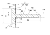
- FIG. 2 is an enlarged cross-sectional view showing a part of a cross section taken along line 2-2 of FIG.
- FIG. 3 is an axial cross-sectional view showing the pancreatic duct cap 120 of the medical device 100 shown in FIG.
- the medical device 100 according to the first embodiment is applied to a procedure for joining the pancreatic parenchyma B1 and the jejunum B2 as shown in FIGS. 10 to 17.
- the medical device 100 is placed between the pancreatic parenchyma B1 and the jejunum B2 (corresponding to a pair of biological organs) to promote fusion between the pancreatic parenchyma B1 and the jejunum B2.
- the pancreatic duct cap 120 (corresponding to one biological organ) covering the opening of the promotion sheet 110 and the pancreatic duct B1b (corresponding to the living organ) and fixing the fusion promoting sheet 110 to the pancreatic parenchyma B1 (Equivalent to a cap) and.
- the medical device 100 may further include an intrusion prevention member 130 that prevents the pancreatic duct cap 120 from entering the patient's body when it falls off the pancreatic duct B1b.
- an intrusion prevention member 130 that prevents the pancreatic duct cap 120 from entering the patient's body when it falls off the pancreatic duct B1b.
- the fusion promoting sheet 110 is formed of a biodegradable sheet having a plurality of through holes 112, and has a main body portion 111 that promotes fusion of living tissues.
- the through holes 112 formed in the main body 111 are regularly and periodically provided in the plane direction of the main body 111. However, each through hole 112 may be randomly provided in each portion of the main body portion 111 in the surface direction.
- each through hole 112 extends substantially vertically between the front surface 113 and the back surface 114 along the thickness direction of the main body 111 (vertical direction in FIG. 2).
- each through hole 112 may be bent or curved in a zigzag shape between the front surface 113 and the back surface 114 in the cross section along the thickness direction of the main body portion 111.
- Each through hole 112 has a substantially circular planar shape (the shape when the front surface 113 of the main body 111 or the back surface 114 of the main body 111 is viewed in a plan view).
- the planar shape of each through hole 112 is not particularly limited, and may be, for example, an ellipse or a polygon (rectangle, triangle, etc.). Further, the plane shape and the cross-sectional shape may be different for each through hole 112.
- the main body 111 has a substantially circular planar shape.
- the planar shape of the main body 111 is not particularly limited, and may be, for example, an ellipse or a polygon (rectangle, triangle, etc.).
- the thickness of the main body 111 is not particularly limited, but is preferably 0.05 to 0.3 mm, more preferably 0.1 to 0.2 mm.
- the strength is such that the main body 111 is not damaged when the fusion promoting sheet 110 is handled.
- the thickness of the main body 111 is 0.3 mm or less (particularly 0.2 mm or less)
- the main body 111 adheres to the biological tissue to which the main body 111 is applied and follows the biological tissue. It can be provided with sufficient flexibility.
- the main body 111 is a value of the ratio of the hole diameter D1 (distance D1 shown in FIG. 2) of the through hole 112 to the pitch P of the through hole 112 (distance P shown in FIG. 2 and the distance between adjacent through holes 112). However, it is preferably 0.25 or more and less than 40. When the planar shape of the through hole 112 is a perfect circle, the hole diameter D1 of the through hole 112 is equal to the diameter of the perfect circle.
- the diameter of a perfect circle having the same area as the area of the opening of the through hole 112 (the portion of the through hole 112 facing the front surface 113 or the back surface 114) ( The equivalent circle diameter) can be the hole diameter D1 of the through hole 112.
- the main body 111 has a plurality of through holes 112, there are a plurality of values of the hole diameter D1 corresponding to each through hole 112. Therefore, in the present embodiment, in calculating the above-mentioned ratio value, the arithmetic mean value of two or more points of the hole diameter D1 corresponding to each of the plurality of through holes 112 is used as the representative value of the hole diameter D1. ..
- the pitch P of the plurality of through holes 112 is defined by the shortest distance between the openings of the two through holes 112. However, as for the value of the pitch P, there are a plurality of values of the pitch P corresponding to the combination of the adjacent through holes 112. Therefore, in the present embodiment, in calculating the above-mentioned ratio value, the arithmetic mean value of two or more points of the pitch P values corresponding to the combinations of the adjacent through holes 112 is used as the representative value of the pitch P. And.
- the pitch P, the hole diameter D1, the ratio of the hole diameter D1 to the pitch P, and the like of the through hole 112 are examples, and are not limited thereto.
- the main body 111 can be made of a biodegradable material.
- the constituent material of the main body 111 is not particularly limited, and examples thereof include biodegradable resins.
- biodegradable resin for example, those described in Japanese Patent Publication No. 2011-528275, Japanese Patent Publication No. 2008-514719, International Publication No. 2008-1952, Japanese Patent Publication No. 2004-509205 and the like are known.
- Biodegradable (co) polymers can be used. Specifically, it is selected from the group consisting of (1) aliphatic polyester, polyester, polyacid anhydride, polyorthoester, polycarbonate, polyphosphazene, polyphosphate ester, polyvinyl alcohol, polypeptide, polysaccharide, protein, and cellulose.
- the biodegradable sheet is selected from the group consisting of aliphatic polyesters, polyesters, polyacid anhydrides, polyorthoesters, polycarbonates, polyphosphazenes, polyphosphates, polyvinyl alcohols, polypeptides, polysaccharides, proteins, and celluloses. It preferably contains at least one biodegradable resin selected from the group consisting of a polymer and a copolymer composed of one or more monomers constituting the polymer.
- the manufacturing method of the main body 111 is not particularly limited, and examples thereof include a method of manufacturing a fiber made of the above-mentioned biodegradable resin and manufacturing a mesh-shaped sheet using the fiber.
- the method for producing the fiber made of a biodegradable resin is not particularly limited, and examples thereof include an electrospinning method (electrospinning method / electrostatic spinning method) and a melt blow method. As the main body 111, only one of the above methods may be selected and used, or two or more of the above methods may be selected and appropriately combined.
- the biodegradable sheet according to the present invention is obtained by spinning the fibers made of the biodegradable resin described above according to a conventional method and knitting the obtained fibers into a mesh shape. May be manufactured.
- the main body 111 induces a biological reaction by a constituent material such as a biodegradable resin constituting the main body 111.
- the main body 111 induces the expression of biological components such as fibrin by this action.
- the biological components induced in this way can promote fusion by accumulating so as to penetrate through the through hole 112 of the main body 111. Therefore, by arranging the main body 111 of the fusion promoting sheet 110 between the pancreatic parenchyma B1 and the jejunum B2, fusion is promoted by the above mechanism.
- the material of the fusion promoting sheet 110 does not have to be biodegradable as long as it can promote the fusion of biological organs. Further, the fusion promoting sheet 110 may not have a through hole 112 formed regardless of the material, as long as it is possible to promote the fusion of living organs.
- pancreatic duct cap 120 As shown in FIGS. 1 and 3, the pancreatic duct cap 120 is connected to a cover portion 121 that covers the opening of the pancreatic duct B1b and a fusion promoting sheet 110 that can be fixed to the pancreatic parenchyma B1.
- a unit 122 is provided.
- the fixation portion 122 in the present embodiment, has an insertion portion 124 that is inserted into the pancreatic duct B1b.
- the pancreatic duct cap 120 in the state where the pancreatic duct cap 120 is attached to the pancreatic parenchyma B1, the side on which the pancreatic parenchyma B1 is arranged is referred to as the "tip side", and the opposite side is referred to as the "base end side”. Further, the direction from the tip end side to the base end side (or the opposite direction) is referred to as an axial direction X, and the direction intersecting the axial direction X is referred to as a radial direction R. In this embodiment, the axial direction X coincides with the extending direction (longitudinal direction) of the insertion portion 124.
- a constant range from the tip (tip end) in the axial direction X is referred to as a tip portion, and a constant range from the proximal end (most proximal end) in the axial direction X is referred to as a proximal end portion.
- the cover portion 121 has a plate-like outer shape in the present embodiment.
- the outer shape of the cover portion 121 in a plan view from the axial direction X is circular.
- the specific shape of the cover portion 121 is not particularly limited as long as it can cover the opening of the pancreatic duct B1b.
- the cover portion 121 may have an elliptical shape or a polygonal outer shape in a plan view from the axial direction X.
- the maximum dimension D2 (diameter D2 in the present embodiment) of the cover portion 121 in the radial direction R is the maximum dimension D3 (diameter in the present embodiment) of the insertion portion 124 in the radial direction R in the present embodiment. It is larger than D3). Therefore, the cover portion 121 can sufficiently cover the opening of the pancreatic duct B1b and prevent the pancreatic duct cap 120 from entering the pancreatic duct B1b.
- the maximum dimension D2 in the radial direction R of the cover portion 121 is not particularly limited, but can be, for example, 1 mm to 50 mm.
- the cover portion 121 is provided with a holding portion 123 that holds one end of the intrusion prevention member 130.
- the holding portion 123 is composed of an insertion portion through which one end of the intrusion prevention member 130 is inserted.
- the configuration of the holding portion 123 is not particularly limited as long as one end of the intrusion prevention member 130 can be held.
- the holding portion 123 may be composed of one end of the intrusion prevention member 130 and an adhesive portion adhered to the cover portion 121.
- the holding portion 123 is arranged on the base end surface 121a of the cover portion 121 in FIG. 1, the position where the holding portion 123 is provided is not particularly limited.
- a non-slip portion (not shown) may be formed to suppress the above.
- the non-slip portion is not particularly limited, but can be composed of, for example, a plurality of groove portions, a plurality of uneven portions, an adhesive layer, and a combination thereof formed on the peripheral surface 121b of the cover portion 121. According to such a configuration, the operator can easily remove the pancreatic duct cap 120 from the pancreatic duct B1b by grasping the peripheral surface 121b of the cover portion 121 with his / her fingers.
- the insertion portion 124 has a long outer shape extending in the axial direction X.
- the tip portion of the insertion portion 124 forms a hole 140 in the fusion promoting sheet 110 by being pressed against the fusion promoting sheet 110.
- the insertion portion 124 is inserted into the pancreatic duct B1b with the hole 140 of the fusion promoting sheet 110 inserted.
- the insertion portion 124 fixes the fusion promoting sheet 110 to the pancreatic parenchyma B1.
- the hole 140 may not be formed by pressing the tip of the insertion portion 124 against the fusion promoting sheet 110, but may be formed in advance on the fusion promoting sheet 110 in a state before use.
- the insertion portion 124 is connected to the central portion in the surface direction of the tip surface 121c (the surface facing the fusion promoting sheet 110) of the cover portion 121.
- the tip of the insertion portion 124 has a tapered shape that tapers from the proximal end side toward the distal end side. Therefore, the operator can easily insert the insertion portion 124 into the pancreatic duct B1b.
- the insertion portion 124 is arranged on the outer diameter constant portion 124a having a substantially constant outer diameter from the tip end side to the proximal end side and on the tip end side of the outer diameter constant portion 124a. It has a tapered portion 124b that is tapered from the proximal end side toward the distal end side.
- the insertion portion 124 may be formed only by the tapered portion from the tip end (tip end) to the base end (most base end). Further, the insertion portion 124 may be formed only by a portion having a substantially constant outer diameter from the tip end (tip end) to the proximal end (most proximal end).
- the maximum dimension D3 (diameter in this embodiment) along the radiation direction R of the insertion portion 124 is not particularly limited as long as it can be inserted into the pancreatic duct B1b, but can be, for example, 1 mm to 5 mm.
- the dimension D4 along the axial direction X of the insertion portion 124 is not particularly limited, but can be, for example, 30 mm to 50 mm.
- the insertion portion 124 is preferably made of a flexible material.
- a material is not particularly limited, and is, for example, a polyolefin or poly composed of polyethylene, polypropylene, polybutene, an ethylene-propylene copolymer, an ethylene-vinyl acetate copolymer, an ionomer, or a mixture of two or more thereof.
- polymer materials such as vinyl chloride, polyamide, polyamide elastomer, polyester, polyester elastomer, polyurethane, polyurethane elastomer, polyimide, and fluororesin, or a mixture thereof, or the above two or more kinds of polymer materials.
- the pancreatic duct cap 120 is a pancreas when the operator inserts a suture member for suturing the pancreatic parenchyma B1 and the jejunum B2 into the pancreatic parenchyma B1 and the jejunum B2 in the procedure of joining the pancreatic parenchyma B1 and the jejunum B2. It is practically attached to B1. Since the pancreatic duct cap 120 does not hang down from the pancreatic duct B1b unlike the conventional pancreatic duct tube, it is unlikely to interfere with the procedure for the operator to insert the suture member into the pancreatic parenchyma B1 and the jejunum B2.
- the operator can easily perform a procedure of inserting the suture member into the pancreatic parenchyma B1 and the jejunum B2 while suppressing the leakage of pancreatic juice (corresponding to body fluid) from the pancreatic duct B1b. it can.
- the fusion promoting sheet 110 is formed with a plurality of through holes 112, the fusion promoting sheet 110 is very soft. Therefore, the union promotion sheet 110 is liable to be twisted or misaligned.
- the fusion promoting sheet 110 is fixed with a biodegradable suture (absorbent thread), staples, or the like. It can be fixed to the pancreatic parenchyma by the member.
- the pancreatic duct cap 120 has the pancreatic duct B1b and the jejunum B2 similar to the conventional pancreatic duct tube after the suture member for suturing the pancreatic parenchyma B1 and the jejunum B2 is inserted into the pancreatic parenchyma B1 and the jejunum B2.
- the suture member is removed from the pancreatic parenchyma B1 so as not to interfere with the procedure of inserting the suture member into the pancreatic duct B1b.
- the pancreatic duct cap 120 according to the present embodiment is configured as an instrument temporarily attached to the pancreatic parenchyma B1 during the procedure.
- pancreatic fluid from the pancreatic duct B1b is applied to the junction between the pancreatic parenchyma B1 and the jejunum B2 using a known device such as a pancreatic duct tube.
- a drainage route may be formed to drain the pancreatic fluid from the pancreatic duct B1b to the outside of the junction so as not to leak.
- the intrusion prevention member 130 is formed of a long member having flexibility such as a thread or a string.
- the intrusion prevention member 130 can prevent the pancreatic duct cap 120 from entering the patient's body when the pancreatic duct cap 120 falls off from the pancreatic duct B1b.
- the other end of the intrusion prevention member 130 may be connected to a living body such as the pancreatic parenchyma B1.
- a needle portion (not shown) is provided at the other end of a long member constituting the intrusion prevention member 130, and the needle portion is hooked on a living body such as the pancreatic parenchyma B1, so that the other end of the intrusion prevention member 130 is pancreatic. It may be substantially connected to B1.
- the medical device 100 has a fusion promoting sheet 110 and a pancreatic duct cap 120.
- the fusion promoting sheet 110 promotes fusion between the pancreatic parenchyma B1 and the jejunum B2 by being arranged between the pancreatic parenchyma B1 and the jejunum B2.
- the pancreatic duct cap 120 includes a cover portion 121 that covers the opening of the pancreatic duct B1b and a fixing portion 122 that is connected to the cover portion 121 and can fix the fusion promoting sheet 110 to the pancreatic parenchyma B1.
- the fusion promoting sheet 110 can be sandwiched between the joined sites of the pancreatic parenchyma B1 and the jejunum B2 to promote the fusion of the biological tissues of the pancreatic parenchyma B1 and the jejunum B2. Further, the fusion promoting sheet 110 can be fixed to the pancreatic parenchyma B1 by the fixing member while the fusion promoting sheet 110 is fixed to the pancreatic parenchyma B1 by the pancreatic duct cap 120. Therefore, it is possible to prevent the fusion promoting sheet 110 from being displaced from the pancreatic parenchyma B1 or being twisted and deformed.
- pancreatic duct cap 120 can suppress the leakage of pancreatic juice from the pancreatic duct B1b by covering the opening of the pancreatic duct B1b during the procedure, and does not hang down from the pancreatic duct B1b unlike the conventional pancreatic duct tube, which hinders the procedure. hard.
- the medical device 100 in the procedure of joining the pancreatic parenchyma B1 and the jejunum B2, the risk of postoperative suture failure can be reduced, and the leakage of pancreatic juice from the pancreatic duct B1b during the procedure can be suppressed.
- the pancreatic parenchyma B1 and the jejunum B2 can be easily joined.
- the fixing portion 122 includes an insertion portion 124 to be inserted into the pancreatic duct B1b.
- the insertion portion 124 can fix the fusion promoting sheet 110 to the pancreatic parenchyma B1 by being inserted into the pancreatic duct B1b with the fusion promoting sheet 110 inserted. Further, since the insertion portion 124 is inserted into the pancreatic duct B1b, leakage of pancreatic juice from the pancreatic duct B1b can be effectively suppressed.
- At least the tip portion of the insertion portion 124 has a tapered shape that tapers from the proximal end side toward the distal end side. Therefore, the operator can easily insert the insertion portion 124 into the pancreatic duct B1b.
- the medical device 100 is formed of a long member having flexibility, one end of which is connected to the pancreatic duct cap 120, and the other end of which is connected to the fusion promoting sheet 110 or at least one of the living body 130. Further have. Therefore, the medical device 100 can effectively prevent the pancreatic duct cap 120 from entering the patient's body.
- FIG. 4A is an axial sectional view showing a modification 1 of the pancreatic duct cap 120 according to the first embodiment
- FIG. 4B is an axial sectional view showing a modification 2 of the pancreatic duct cap 120 according to the first embodiment.
- the fixing portion 122 constituting the pancreatic duct cap 120 may further have a movement suppressing portion 125 capable of suppressing the movement of the insertion portion 124 in the pancreatic duct B1b.
- the movement suppressing portion 125 is arranged between the tip end (tip end) and the proximal end (most proximal end) of the insertion portion 124 and intersects the longitudinal direction (axial direction X) of the insertion portion 124.
- the expansion portion 126a that can expand and contract in the radial direction R may be used.
- the expansion portion 126a forms an internal space 126b into which the fluid is injected between the expansion portion 126a and the insertion portion 124.
- a communication passage 126c is formed in the cover portion 121 and the insertion portion 124.
- the cover portion 121 is provided with an opening 126d that communicates with the communication passage 126c and into which a fluid injection device (not shown) such as a syringe is inserted, and a valve body 126e that covers the opening 126d.
- a fluid injection device such as a syringe is inserted into the opening 126d with the insertion portion 124 inserted into the pancreatic duct B1b, and the fluid is injected into the internal space 126b by the injection device.
- the expansion portion 126a expands outward in the radial direction R and is pressed against the inner wall of the pancreatic duct B1b. Therefore, the expansion portion 126a can effectively suppress the movement of the insertion portion 124 in the pancreatic duct B1b.
- the valve body 126e closes the opening 126d airtightly or liquidtightly. Therefore, the expansion unit 126a can maintain the expanded state.
- a fluid injection device such as a syringe is inserted into the opening 126d again, and the fluid is discharged from the internal space 126b by the injection device.
- the expansion portion 126a contracts inward in the radial direction R. Therefore, the user can easily remove the insertion portion 124 from the pancreatic duct B1b.
- the movement suppressing unit 125 may be an adsorption unit 127a that can be adsorbed on the inner wall of the pancreatic duct B1b.
- the suction portion 127a can be composed of, for example, a plurality of suction holes 127b that open on the peripheral surface of the insertion portion 124.
- the cover portion 121 and the insertion portion 124 are formed with a communication passage 127c communicating with the suction hole 127b.
- the cover portion 121 is provided with an opening 127d, which communicates with the communication passage 127c and into which a suction device (not shown) such as a syringe is inserted, and a valve body 127e, which covers the opening 127d.
- a suction device such as a syringe is inserted into the opening 127d to perform suction.
- the adsorption portion 127a is adsorbed on the inner wall of the pancreatic duct B1b.
- the valve body 127e closes the opening 127d airtightly or liquidtightly. Therefore, the adsorption portion 127a can effectively suppress the movement of the insertion portion 124 in the pancreatic duct B1b.
- the configuration of the expansion portion 126a and the suction portion 127a is not limited to the above.
- the injection of a fluid into the internal space 126b of the expansion portion 126a is not an injection device such as a syringe, but a bag-shaped injection member or the like which is connected to the opening 126d and injects the fluid into the internal space 126b by being crushed. It may be configured by.
- the fixing portion 122 may further have a movement suppressing portion 125 that suppresses the movement of the insertion portion 124 in the pancreatic duct B1b. Therefore, the movement suppressing portion 125 can effectively prevent the insertion portion 124 from falling out of the pancreatic duct B1b.
- the movement suppressing portion 125 may be an expansion portion 126a that can expand and contract in the radial direction R that intersects the axial direction X of the insertion portion 124 between the tip end and the base end of the insertion portion 124.
- the dilation portion 126a expands outward in the radial direction R and is pressed against the inner wall of the pancreatic duct B1b. Therefore, the expansion portion 126a can effectively prevent the insertion portion 124 from falling out of the pancreatic duct B1b. Further, by pressing the dilation portion 126a against the inner wall of the pancreatic duct B1b, it is possible to effectively prevent pancreatic juice from leaking from the pancreatic duct B1b.
- the movement suppressing unit 125 may be an adsorption unit 127a capable of adsorbing to the inner wall of the pancreatic duct B1b.
- the adsorption portion 127a adsorbs to the inner wall of the pancreatic duct B1b. Therefore, the adsorption portion 127a can effectively prevent the insertion portion 124 from falling off from the pancreatic duct B1b.
- 5A and 5B are axial cross-sectional views showing a modification 3 of the pancreatic duct cap 120 according to the first embodiment.
- the fixing portion 122 constituting the pancreatic duct cap 120 may further have a removal assisting portion 128 that assists in removing the insertion portion 124 from the pancreatic duct B1b.
- the removal assisting portion 128 is provided at least at the base end portion of the insertion portion 124, and is contracted inward in the radial direction R intersecting the axial direction X of the insertion portion 124, and is in the radial direction R. It is composed of an expansion unit 128a that can shift to an expanded state that is expanded outward. As shown in FIG. 5B, the expansion portion 128a has an outer shape that tapers from the proximal end side toward the distal end side in the expanded state.
- the expansion portion 128a forms an internal space 128b into which a fluid is injected between the tip end surface 121c of the cover portion 121 and the base end portion of the insertion portion 124.
- the cover portion 121 and the insertion portion 124 are formed with a communication passage 128c communicating with the internal space 128b.
- the cover portion 121 is provided with an opening 128d that communicates with the communication passage 128c and into which a fluid injection device (not shown) such as a syringe is inserted, and a valve body 128e that covers the opening 128d.
- the expansion portion 128a expands outward in the radial direction R as shown in FIG. 5B.
- the expansion portion 128a is provided at the base end portion of the insertion portion 124, and has an outer shape that tapers from the base end side toward the tip end side in the expanded state. Therefore, the expanded dilated portion 128a presses the pancreatic duct B1b so that the cover portion 121 is separated from the pancreatic parenchyma B1. Therefore, the operator can easily remove the pancreatic duct cap 120 from the pancreatic duct B1b.
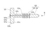
- FIG. 6 is an axial sectional view showing a modified example 4 of the pancreatic duct cap 120 according to the first embodiment.
- the insertion portion 124 constituting the pancreatic duct cap 120 may be provided with an absorbing member 129 that absorbs body fluid such as pancreatic juice.
- the absorbing member 129 is made of a porous material such as a sponge, and absorbs body fluid such as pancreatic juice in a state where the insertion portion 124 is inserted into the pancreatic duct B1b. Therefore, the absorbing member 129 can effectively prevent body fluid such as pancreatic juice from leaking from the pancreatic duct B1b.
- a hole portion 124c extending in the longitudinal direction (axial direction X) of the insertion portion 124 is formed at the tip end portion of the insertion portion 124, and the absorbing member 129 is arranged in the hole portion 124c. Therefore, the operator can easily insert the insertion portion 124 into the pancreatic duct B1b.
- the absorbing member 129 may be provided on the outer surface of the insertion portion 124.
- the insertion portion 124 may be provided with an absorbing member 129 capable of absorbing body fluids. With such a configuration, it is possible to effectively suppress the leakage of pancreatic juice from the pancreatic duct B1b.
- FIG. 7 is a perspective view showing a modified example 5 of the pancreatic duct cap 120 according to the first embodiment.
- the fixing portion 122 constituting the pancreatic duct cap 120 may be formed not by the insertion portion 124 but by a plurality of needle portions 224 provided on the tip surface 121c of the cover portion 121. ..
- the plurality of needle portions 224 are provided on the distal end surface 121c of the cover portion 121 on the outer side of the radial direction R with respect to the region A covering the opening of the pancreatic duct B1b.
- the plurality of needles 224 are punctured into the pancreatic parenchyma B1 through the fusion promoting sheet 110.
- the plurality of needles 224 fix the fusion promoting sheet to the pancreatic parenchyma B1.
- the plurality of needle portions 224 are provided at substantially equal intervals in the circumferential direction around the axial direction X.
- the number and position of the needle portions 244 are not particularly limited.
- the fixing portion 122 may include both the insertion portion 124 and the plurality of needle portions 224.
- FIG. 8 is a perspective view showing a modification 6 of the pancreatic duct cap 120 according to the first embodiment.
- the pancreatic duct cap 120 may further have a frame portion 225 that is connected to the cover portion 121, extends in the radial direction R, and holds the fusion promoting sheet 110 removably.
- the frame portion 225 is composed of a plurality of rod-shaped members 226.
- Each rod-shaped member 226 extends from the cover portion 121 toward the outside in the radial direction R.
- the end portion 226b on the outer side of the radial direction R of each rod-shaped member 226 is located closer to the base end side than the end portion 226a on the inner side of the radial direction R of each rod-shaped member 226. It is curved. Therefore, when the fusion promoting sheet 110 is arranged on the pancreatic parenchyma B1, the fusion promoting sheet 110 is sequentially arranged from the central portion of the radiation direction R of the fusion promotion sheet 110 toward the outer side portion of the radiation direction R. It attaches to pancreatic parenchyma B1. As a result, it is possible to effectively suppress the twisting and misalignment of the fusion promoting sheet 110.
- FIG. 9 is a flowchart showing each procedure of a treatment method for joining the pancreatic parenchyma and the jejunum using a medical device.
- the treatment method is to use a fusion promoting sheet that promotes the fusion of living tissue formed from a biodegradable sheet having multiple through holes, and a cover portion that covers the opening of the pancreatic duct and a fusion promoting sheet that is connected to the cover portion. It comprises preparing a medical device having a pancreatic duct cap having a fixation portion that can be fixed to the pancreatic parenchyma (S101). The treatment method further comprises arranging the medical device so that the cover covers the opening of the pancreatic duct and the fixation part fixes the fusion promotion sheet to the pancreatic parenchyma (S102), and the fusion promotion sheet is fixed to the pancreas with a fixing member. It includes fixing to the substance (S103).
- the treatment method further includes forming a drainage route for draining pancreatic juice from the pancreatic duct to the outside of the junction so that the pancreatic juice in the pancreatic duct does not leak to the junction between the pancreatic parenchyma and the jejunum (S104).
- the treatment method further involves sandwiching at least a part of the fusion promoting sheet between the pancreatic parenchyma and the jejunum (S105), and joining with at least a part of the fusion promoting sheet sandwiched between the pancreatic parenchyma and the jejunum. This includes placing a fusion-promoting sheet between the pancreatic parenchyma and the jejunum (S107).
- any medical device can be selected from the above-mentioned medical devices, and other medical devices can also be selected.
- a usage example of a specific medical device will be described as a typical example that can be suitably used for each procedure.
- detailed description of known procedure procedures, known medical devices, medical instruments, etc. will be omitted as appropriate.
- arranging the fusion promoting sheet between the pancreatic parenchyma and the jejunum means that the fusion promoting sheet is placed in direct or indirect contact with the pancreatic parenchyma or the jejunum.
- the fusion-promoting sheet is placed with a spatial gap formed between the pancreatic parenchyma and the jejunum, or the fusion-promoting sheet is placed in both states (eg, pancreatic parenchyma and jejunum). It means at least one of (the fusion promoting sheet is in contact with one biological organ and the fusion promoting sheet is not in contact with the other biological organ).
- peripheral does not define a strict range (region), but a predetermined range (region) as long as the purpose of treatment (joining of pancreatic parenchyma and jejunum) can be achieved. ) Means.
- order of the procedure procedures described in each treatment method can be changed as appropriate as long as the purpose of the treatment can be achieved.
- relatively approaching means both bringing two or more objects to be approached close to each other and bringing only one close to the other.
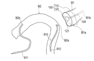
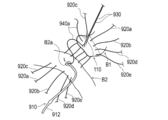
- FIGS. 10 to 17 are diagrams for explaining pancreatic parenchymal-jejunal anastomosis.
- a plurality of both end needles 920a to 920e which will be described later, are omitted.
- an example of the treatment method will be described with reference to FIGS. 10 to 17.
- an example of using the medical device 100 shown in FIG. 1 will be described.
- the surgeon prepares a medical device 100 having a fusion promoting sheet 110 and a pancreatic duct cap 120.
- the surgeon has a medical device such that the cover portion 121 covers the opening of the pancreatic duct B1b and the fixation portion 122 (insertion portion 124) fixes the fusion promoting sheet 110 to the pancreatic parenchyma B1.
- 100 is placed on the cut surface B1a of the pancreatic parenchyma B1.
- the specific procedure for arranging the medical device 100 on the cut surface B1a of the pancreatic parenchyma B1 is not particularly limited, but for example, the following procedure can be performed.
- the operator attaches the fusion promoting sheet 110 to the cut surface B1a.
- the operator inserts the insertion portion 124 into the pancreatic duct B1b while forming a hole 140 in the fusion promotion sheet 110 by pressing the tip of the insertion portion 124 of the pancreatic duct cap 120 against the fusion promotion sheet 110.
- pancreatic duct cap 120 causes pancreatic juice to leak from the pancreatic duct B1b when the operator inserts a suture member (both ends needles 920a to 920e) for suturing the pancreatic parenchyma B1 and the jejunum B2 into the pancreatic parenchyma B1 and the jejunum B2. Suppress that.
- the pancreatic duct tube 910 may be inserted into the jejunum B2.
- a known resin tube having a bump (convex portion) formed at the end portion 912 to prevent removal can be used.
- the operator may use another device such as the pancreatic duct tube 910 instead of the pancreatic duct cap 120 when forming the hole 140 through which the pancreatic duct cap 120 is inserted.
- the hole 140 through which the pancreatic duct cap 120 is inserted may be formed in advance in the fusion promoting sheet 110 in a state before use. Further, the operator may insert the insertion portion 124 into the pancreatic duct B1b after inserting the insertion portion 124 into the hole portion 140 of the fusion promoting sheet 110.
- the operator fixes the fusion promoting sheet 110 to the pancreatic parenchyma B1 with a fixing member.
- a procedure for fixing the fusion promoting sheet 110 to the pancreatic parenchyma B1 by using a plurality of both end needles 920a to 920e as fixing members will be described.
- known needles having a bioabsorbable absorbent thread (suture) and a biocompatible needle portion attached to both ends of the absorbent thread can be used.
- the needles 930 and 940a to 940e at both ends which will be described later, are also configured to include an absorbent thread and a needle portion.
- the surgeon starts with the posterior wall B1c of the pancreatic parenchyma B1 (the dorsal portion of the pancreatic parenchyma B1 in the circumferential direction) and the portion arranged on the posterior wall B1c in the fusion promoting sheet 110.
- Both ends needles 920a are moved toward the anterior wall B1d of the pancreatic parenchyma B1 (the ventral portion of the pancreatic parenchyma B1 in the circumferential direction) and the portion of the fusion promoting sheet 110 arranged on the anterior wall B1d.
- the operator moves both ends of the needle 920a so as to insert the jejunal serosal muscular layer at the planned anastomosis site of the jejunum B2 (around the through hole B2a).
- the operator repeats such an operation, and inserts a plurality of both end needles 920a to 920e into the jejunal serosal muscular layer of the fusion promoting sheet 110, the pancreatic parenchyma B1, and the jejunum B2 as shown in FIG.
- the operator can fix the fusion promoting sheet 110 to the pancreatic parenchyma B1 by using a plurality of both end needles 920a to 920e that suture the pancreatic parenchyma B1 and the jejunum B2.
- the operator can fix the fusion promoting sheet 110 to the pancreatic parenchyma B1 using the needles 920a to 920e at both ends in a state where the fusion promoting sheet 110 is fixed to the pancreatic parenchyma B1 by the pancreatic duct cap 120. Therefore, when the operator fixes the fusion promoting sheet 110 to the pancreatic parenchyma B1 using the needles 920a to 920e at both ends, it is possible to prevent the fusion promoting sheet 110 from being displaced from the pancreatic parenchyma B1 or being twisted and deformed.
- the number of both-end needles to be inserted into the jejunal serosal muscular layer of the pancreatic parenchyma B1 and the jejunum B2 and the position to insert the both-end needles are not particularly limited. Further, the operator may fix the fusion promoting sheet 110 to the pancreatic parenchyma B1 by using biodegradable staples or the like as a fixing member instead of the plurality of needles 920a to 920e at both ends.
- the operator passes the needles 930 at both ends from the lumen side of the pancreatic duct B1b toward the anterior wall B1d side of the cut surface B1a of the pancreatic parenchyma B1.
- the needles 930 at both ends are held by a gripping instrument such as tweezers (not shown) so as not to interfere with the procedure in a state where the jejunum B2 is not inserted.
- the operator moves one end of the needles 940a at both ends from the lumen side of the pancreatic duct B1b toward the cut surface B1a of the pancreatic parenchyma B1.
- the operator inserts the other end of the needles 940a at both ends into the through hole B2a of the jejunum B2, and the needles 940a at both ends toward the outside of the jejunum B2 from the inside of the jejunum B2. Move the other end.
- the operator inserts a plurality of both-end needles 940a to 940e into different sites in the circumferential direction of the pancreatic duct B1b and the jejunum B2.
- the operator brings the posterior wall B1c of the pancreatic parenchyma B1 and the pancreatic duct B1b into close contact with the planned anastomosis site of the jejunum B2. Then, of the plurality of needles 940a to 940e at both ends, the needles 940c to 940e at both ends that insert the dorsal side (rear wall B1c side) of the pancreatic duct B1b in the circumferential direction are ligated.
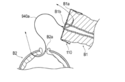
- the operator inserts the end 912 of the pancreatic duct tube 910 into the pancreatic duct B1b, as shown in FIG. As a result, a drainage route is formed for discharging the pancreatic juice from the pancreatic duct B1b to the outside of the junction so that the pancreatic juice from the pancreatic duct B1b does not leak to the junction between the pancreatic parenchyma B1 and the jejunum B2.
- the operator inserts the needle portion 931 extending from the inside of the pancreatic duct B1b with the needles 930 at both ends into the through hole B2a formed in the jejunum B2, and inserts the needle portion 931 from the inside of the jejunum B2 toward the outside of the jejunum B2. Move the hands.
- the operator ligates the needles 930, 940a, and 940b at both ends (not shown).
- the number of both-end needles to be inserted into the pancreatic duct B1b and the jejunum B2 and the position to insert the both-end needles are not particularly limited.
- the operator ligates the needles 920a to 920e at both ends while pressing the jejunum B2 against the pancreatic parenchyma B1 with the operator's finger.
- the pancreatic parenchyma B1 and the jejunum B2 are sutured with the fusion promoting sheet 110 sandwiched between them.
- the jejunum B2 is deformed by the tension generated at the time of suturing so as to wrap the cut surface B1a of the pancreatic parenchyma B1 and the main body 111 of the fusion promoting sheet 110.
- the operator places the fusion promoting sheet 110 in a state where the main body 111 of the medical device 100 is sandwiched between the cut surface B1a of the pancreatic parenchyma B1 and the intestinal wall of the jejunum B2.
- the operator places the pancreatic duct tube 910 so that the end portion 911 of the pancreatic duct tube 910 is led out of the body. That is, the pancreatic duct tube 910 functions as a so-called external fistula tube.
- the main body 111 of the fusion promoting sheet 110 is placed between the cut surface B1a of the pancreatic parenchyma B1 and the intestinal wall of the jejunum B2 while being in contact with the cut surface B1a of the pancreatic parenchyma B1 and the intestinal wall of the jejunum B2. This promotes the fusion of the biological tissue of the pancreatic parenchyma B1 and the biological tissue of the intestinal wall of the jejunum B2.
- the treatment method according to the present embodiment is applied to the procedure for joining the pancreatic parenchyma B1 and the jejunum B2. Further, in the above treatment method, the periphery of the cut surface B1a of the cut pancreatic parenchyma B1 and the intestinal wall (jejunal serosal muscular layer) of the jejunum B2 are joined. According to this treatment method, the biological tissue of the pancreatic parenchyma B1 and the biological tissue of the intestinal wall of the jejunum B2 are formed by the main body 111 of the fusion promoting sheet 110 sandwiched between the cut surface B1a of the pancreatic parenchyma B1 and the intestinal wall of the jejunum B2. Can promote fusion and reduce the risk of suture failure after pancreatic parenchymal-jejunostomy.
- the operator cuts the medical device 100 of the pancreatic parenchyma B1 so that the cover portion 121 covers the opening of the pancreatic duct B1b and the fixing portion 122 fixes the fusion promoting sheet 110 to the pancreatic parenchyma B1. It is arranged on the surface B1a. Then, the operator fixes the fusion promoting sheet 110 to the pancreatic parenchyma B1 using fixing members (both ends needles 920a to 920e). Therefore, the fusion promoting sheet 110 can be fixed to the pancreatic parenchyma B1 by the fixing member while the fusion promoting sheet 110 is fixed to the pancreatic parenchyma B1 by the pancreatic duct cap 120.
- the pancreatic duct cap 120 covers the opening of the pancreatic duct B1b when the fusion promoting sheet 110 is fixed to the pancreatic parenchyma B1 with a fixing member.
- the pancreatic duct cap 120 does not hang down from the pancreatic duct B1b unlike the conventional pancreatic duct tube, and is less likely to interfere with the procedure as compared with the conventional pancreatic duct tube. Therefore, according to the above-mentioned treatment method, the pancreatic parenchyma B1 and the jejunum B2 can be easily joined while suppressing the leakage of pancreatic juice during the procedure.
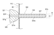
- FIG. 18 is a perspective view showing the pancreatic duct cap 320 according to the second embodiment.
- FIG. 19 is an axial sectional view showing the pancreatic duct cap 320 shown in FIG.
- the pancreatic duct cap 320 according to the first embodiment is configured so that it does not need to be removed when the suture members (both ends needles 930, 940a to 940e) are inserted into the pancreatic duct B1b. It is different from the cap 120.
- the pancreatic duct cap 320 according to the second embodiment will be described. The same configuration as that described in the medical device 100 according to the first embodiment will be omitted as appropriate.
- the pancreatic duct cap 320 includes a cover portion 321 that covers the opening of the pancreatic duct B1b, and a fixing portion 322 that is connected to the cover portion 321 and can fix the fusion promoting sheet 110 to the pancreatic parenchyma B1. , Equipped with.
- the fixation portion 322 has, in this embodiment, an insertion portion 324 that is inserted into the pancreatic duct B1b.
- the tip of the cover portion 321 has a convex shape toward the tip side. Therefore, the cover portion 321 forms a space S between the cover portion 321 and the cut surface B1a of the pancreatic parenchyma B1 in a state of being attached to the pancreatic parenchyma B1. Therefore, the operator passes the suture members (both ends needles 930, 940a to 940e) used for suturing the pancreatic duct B1b and the jejunum B2 through the space S while the cover portion 321 is fixed to the pancreatic parenchyma B1. The suture member can be inserted into the pancreatic duct B1b.
- the pancreatic duct cap 320 is used not only when the suture members (both ends needles 920a to 920e) are inserted into the pancreatic parenchyma B1 and the jejunum B2, but also when the suture members (both ends needles 930 and 940a to 940e) are inserted into the pancreatic duct B1b. Also, the leakage of pancreatic juice from the pancreatic duct B1b can be suppressed.
- the tip of the cover portion 321 may be provided with a holding portion 321a capable of holding the pancreatic duct B1b and / or the living tissue in the vicinity thereof.
- the holding portion 321a can be composed of, for example, a plurality of needle portions 321b.
- the plurality of needle portions 321b are provided at positions different from the positions through which the suture members (both ends needles 930, 940a to 940e) pass in the circumferential direction of the cover portion 321.
- the suture member is inserted into the pancreatic duct B1b
- the operator pulls the cover portion 321 toward the proximal end side, so that the holding portion 321a moves toward the proximal end side.
- the living tissue in the pancreatic duct B1b and / or its vicinity protrudes toward the proximal end side with respect to the other region of the cut surface B1a. Therefore, the operator can easily insert the end of the suture member into the lumen of the pancreatic duct B1b.
- each needle portion 321b has a linearly extending shape, but may have a hook-shaped curved shape.
- the cover portion 321 is configured to be removable from the insertion portion 324, the insertion portion 324 is formed of a biodegradable material, and the insertion portion 324 has a cavity 324a that penetrates the insertion portion 324 in the axial direction X. May be formed. According to such a configuration, after the suture member is inserted into the pancreatic duct B1b, the cover portion 321 can be removed from the insertion portion 324 and inserted into the through hole B2a of the jejunum B2 at the base end portion of the insertion portion 324.
- the insertion portion 324 is in vivo together with the fusion promoting sheet 110 in a state where the tip end portion of the insertion portion 324 is inserted into the pancreatic duct B1b and the base end portion of the insertion portion 324 is inserted into the through hole B2a of the jejunum B2. Detained in.
- the indwelling insertion portion 324 discharges the pancreatic juice from the pancreatic duct B1b into the jejunum B2 so that the pancreatic juice from the pancreatic duct B1b does not leak to the junction between the pancreatic parenchyma B1 and the jejunum B2.
- the pancreatic duct cap 320 may be configured such that the insertion portion 324 functions as a so-called internal fistula tube.
- the method of configuring the insertion portion 324 to be removable from the cover portion 321 is not particularly limited, but for example, a method of forming a detachable engaging portion between the cover portion 321 and the insertion portion 324, the cover portion 321 and the insertion portion 324. Examples thereof include a method of forming a break portion capable of separating the cover portion 321 and the insertion portion 324 at the boundary portion between them.
- FIG. 19 shows a female screw portion 321c formed on the cover portion 321 and a male screw portion 324b formed on the insertion portion 324 as an example of the detachable engaging portion.
- the cover portion 321 is not configured to be removable from the insertion portion 324, and the pancreatic duct cap 320 may be removed from the pancreatic parenchyma B1 after the suture member is inserted into the pancreatic duct B1b and the jejunum B2.
- a known device such as a pancreatic duct tube may be used as the external fistula tube in the same manner as the above-mentioned treatment method.
- the cover portion 321 is formed with a space S through which the suturing member used for suturing the pancreatic duct B1b and the jejunum B2 passes. Since it is not necessary to remove the pancreatic duct cap 320 when inserting the suture member into the pancreatic duct B1b, the pancreatic duct cap 320 is used only when the suture member for suturing the pancreatic parenchyma B1 and the jejunum B2 is inserted into the pancreatic parenchyma B1 and the jejunum B2.
- pancreatic fluid from the pancreatic duct B1b can be suppressed.
- the cover portion 321 is configured to be removable from the insertion portion 324, the insertion portion 324 is formed of a biodegradable material, and the insertion portion 324 has a cavity 324a penetrating the insertion portion 324 in the axial direction X. May be formed. According to such a configuration, since the insertion portion 324 can function as an internal fistula tube, it is not necessary to use another device such as a pancreatic duct tube.
- FIG. 20 is a perspective view showing a modification 1 of the pancreatic duct cap 320 according to the second embodiment.
- the space S through which the suturing member used for suturing the pancreatic duct B1b and the jejunum B2 passes is formed over the entire circumference of the cover portion 321.
- the groove portion 321d recessed inward in the radial direction R is moved in the circumferential direction of the cover portion 321.
- a plurality may be formed.
- each groove portion 321d forms a space S through which each suture member passes
- the space S through which the suture member used for suturing the pancreatic duct B1b and the jejunum B2 passes is partially formed in the circumferential direction of the cover portion 321. ..
- eight groove portions 321d are formed in the cover portion 321 so that the eight suture members can pass through, but the number and position of the groove portions 321d are appropriately determined according to the number and position of the suture members to be passed. It can be changed.
- FIG. 21 is an axial sectional view showing a modification 2 of the pancreatic duct cap 320 according to the second embodiment.
- the fixing portion 322 may further have a movement suppressing portion 325 that suppresses the movement of the insertion portion 324 in the pancreatic duct B1b.
- the movement suppressing portion 325 is arranged between the tip end (tip end) and the base end (most base end) of the insertion portion 324, and the radial direction R intersects the axial direction X of the insertion portion 324. It may be an expansion portion 326a that can be expanded and contracted.
- the expansion portion 326a forms an internal space 326b into which the fluid is injected between the expansion portion 326a and the insertion portion 324.
- the cover portion 321 and the insertion portion 324 are formed with a communication passage 326c communicating with the internal space 326b.
- the cover portion 321 is provided with an opening 326d that communicates with the communication passage 326c and into which a fluid injection device (not shown) such as a syringe is inserted.
- the insertion portion 324 is provided with a check valve 326e that allows the inflow of fluid from the communication passage 326c into the internal space 326b but prohibits the outflow in the reverse direction.
- a fluid injection device such as a syringe is inserted into the opening 326d with the insertion portion 324 inserted into the pancreatic duct B1b, and the fluid is injected into the internal space 326b by the injection device.
- the expansion portion 326a expands outward in the radial direction R and is pressed against the inner wall of the pancreatic duct B1b. Therefore, the expansion portion 326a can effectively suppress the movement of the insertion portion 324 in the pancreatic duct B1b.
- the cover portion 321 is removed from the insertion portion 324, and the base end portion of the insertion portion 324 is inserted into the through hole B2a of the jejunum B2. Then, the insertion portion 324 is placed in the living body.
- a check valve 326e is provided in the insertion portion 324. Therefore, even when the insertion portion 324 is indwelled in the living body, the expansion portion 326a can effectively suppress the movement of the insertion portion 324 in the pancreatic duct B1b.
- the movement suppressing portion 325 may be formed not by the expansion portion 326 but by an adsorption portion that can be adsorbed on the inner wall of the pancreatic duct B1b.
- FIGS. 22A to 22C are axial sectional views showing a modification 3 of the pancreatic duct cap 320 according to the second embodiment.
- the pancreatic duct cap 320 may be configured such that the cover portion 321 and the insertion portion 324 are split in the axial direction X.
- the cover portion 321 is formed with a lumen 321e communicating with the lumen 324a of the insertion portion 324. Further, the cover portion 321 is provided with an opening 321f communicating with the lumen 321e of the cover portion 321 and a check valve 321g covering the opening 321f. As shown in FIG. 22B, the check valve 321g is configured so that the end portion 912 of the pancreatic duct tube 910 can be inserted into the lumen 321e of the cover portion 321 without tearing the cover portion 321.
- the cover portion 321 and the insertion portion 324 are formed with a fracture portion 327 which is a starting point of fracture when the cover portion 321 and the insertion portion 324 are pulled in opposite directions in the direction extending in the X-axis direction and intersecting the X-axis.
- the fractured portion 327 can be formed by, for example, a thin-walled portion or a notched portion having a wall thickness thinner than that of other regions.
- the operator After inserting the suture member into the pancreatic duct B1b, the operator performed the pancreatic duct tube 910 from the check valve 321 g of the cover portion 321 to the lumen 321e of the cover portion 321 and the lumen 324a of the insertion portion 324, as shown in FIG. 22B. Insert the end 912 of the.
- the operator tears the cover portion 321 and the insertion portion 324 in the axial direction X while maintaining the state in which the pancreatic duct tube 910 is arranged in the pancreatic duct B1b, and the pancreatic duct from the pancreatic parenchyma B1. Remove the cap 320.
- pancreatic duct tube 910 can be inserted into the pancreatic duct B1b without removing the pancreatic duct cap 320. Therefore, it is possible to effectively suppress the leakage of pancreatic juice from the pancreatic duct B1b during the procedure.
- the medical device according to the present invention has been described above through a plurality of embodiments and modifications, the present invention is not limited to each of the described configurations, and may be appropriately modified based on the description of the scope of claims. Is possible.
- the medical device according to the present invention may be applied to the junction of the pancreatic parenchyma and other biological organs other than the jejunum.
- 100 medical devices 110 healing promotion sheet, 112 through hole, 120, 320 pancreatic duct cap (cap), 121, 321 Cover part 122, 322 Fixed part, 124, 324 insertion part, 125, 325 movement restraint, 126a, 326a extension, 127a Adsorption part, 129 Absorbent member, 130 Intrusion prevention member, 910 Pancreatic duct tube, B1 Pancreatic parenchyma (biological organ), B1b pancreatic duct (living lumen), B2 jejunum (biological organ), R radiation direction, S Space through which the suture member passes, X-axis direction.
Abstract
Le problème à résoudre par la présente invention est de fournir un dispositif médical permettant de réduire le risque de défaillance de suture postopératoire, d'assembler facilement une paire d'organes biologiques tout en éliminant une fuite de fluide corporel d'une lumière d'organe biologique pendant une procédure chirurgicale. La solution de l'invention porte sur un dispositif médical (100) qui comprend : une feuille de promotion de fusion (110) disposée entre une paire d'organes biologiques (B1, B2) de façon à favoriser la fusion de la paire d'organes biologiques ; et un capuchon (120) comprenant une partie couvercle (121) qui recouvre une ouverture d'une lumière biologique (B1b) d'un organe biologique (B1) entre la paire d'organes biologiques (B1, B2), et une partie de fixation (122) qui est reliée à la partie couvercle et qui est apte à fixer la feuille de promotion de fusion à l'organe biologique.
Priority Applications (1)
| Application Number | Priority Date | Filing Date | Title |
|---|---|---|---|
| JP2021509652A JP7376572B2 (ja) | 2019-03-28 | 2020-03-27 | 医療デバイス |
Applications Claiming Priority (2)
| Application Number | Priority Date | Filing Date | Title |
|---|---|---|---|
| JP2019064736 | 2019-03-28 | ||
| JP2019-064736 | 2019-03-28 |
Publications (1)
| Publication Number | Publication Date |
|---|---|
| WO2020196856A1 true WO2020196856A1 (fr) | 2020-10-01 |
Family
ID=72608455
Family Applications (1)
| Application Number | Title | Priority Date | Filing Date |
|---|---|---|---|
| PCT/JP2020/014143 WO2020196856A1 (fr) | 2019-03-28 | 2020-03-27 | Dispositif médical |
Country Status (2)
| Country | Link |
|---|---|
| JP (1) | JP7376572B2 (fr) |
| WO (1) | WO2020196856A1 (fr) |
Cited By (1)
| Publication number | Priority date | Publication date | Assignee | Title |
|---|---|---|---|---|
| WO2023032692A1 (fr) * | 2021-09-03 | 2023-03-09 | テルモ株式会社 | Élément médical |
Citations (2)
| Publication number | Priority date | Publication date | Assignee | Title |
|---|---|---|---|---|
| JP2011015966A (ja) * | 2009-07-08 | 2011-01-27 | Tyco Healthcare Group Lp | 外科用ガスケット |
| JP2019162405A (ja) * | 2018-03-19 | 2019-09-26 | テルモ株式会社 | 処置方法 |
Family Cites Families (15)
| Publication number | Priority date | Publication date | Assignee | Title |
|---|---|---|---|---|
| US5176703A (en) * | 1991-10-30 | 1993-01-05 | Peterson Meldon L | Sutureless closure for a skin wound or incision |
| US5695504A (en) * | 1995-02-24 | 1997-12-09 | Heartport, Inc. | Devices and methods for performing a vascular anastomosis |
| IL152817A0 (en) * | 2000-05-19 | 2003-06-24 | Coapt Systems Inc | Tissue approximation device and a method using it |
| US7547312B2 (en) * | 2003-09-17 | 2009-06-16 | Gore Enterprise Holdings, Inc. | Circular stapler buttress |
| US8372094B2 (en) * | 2004-10-15 | 2013-02-12 | Covidien Lp | Seal element for anastomosis |
| US7942890B2 (en) * | 2005-03-15 | 2011-05-17 | Tyco Healthcare Group Lp | Anastomosis composite gasket |
| GB2430372B (en) * | 2005-09-19 | 2010-09-29 | Stephen George Edward Barker | Reinforcement device |
| US8052699B1 (en) * | 2007-05-15 | 2011-11-08 | Cook Medical Technologies Llc | Viscerotomy closure device and method of use |
| US8439945B2 (en) * | 2010-05-03 | 2013-05-14 | Zipline Medical, Inc. | Methods for biopsying tissue |
| US8464925B2 (en) * | 2010-05-11 | 2013-06-18 | Ethicon Endo-Surgery, Inc. | Methods and apparatus for delivering tissue treatment compositions to stapled tissue |
| US10820895B2 (en) * | 2011-01-11 | 2020-11-03 | Amsel Medical Corporation | Methods and apparatus for fastening and clamping tissue |
| US8967448B2 (en) * | 2011-12-14 | 2015-03-03 | Covidien Lp | Surgical stapling apparatus including buttress attachment via tabs |
| US9010612B2 (en) * | 2012-01-26 | 2015-04-21 | Covidien Lp | Buttress support design for EEA anvil |
| US10052105B2 (en) * | 2013-11-18 | 2018-08-21 | Ethicon, Inc. | Recessed surgical fastening devices |
| DE102015205056A1 (de) * | 2015-03-20 | 2016-09-22 | Aesculap Ag | Chirurgisches Gewebefusionsinstrument und Stützstruktur hierfür |
-
2020
- 2020-03-27 JP JP2021509652A patent/JP7376572B2/ja active Active
- 2020-03-27 WO PCT/JP2020/014143 patent/WO2020196856A1/fr active Application Filing
Patent Citations (2)
| Publication number | Priority date | Publication date | Assignee | Title |
|---|---|---|---|---|
| JP2011015966A (ja) * | 2009-07-08 | 2011-01-27 | Tyco Healthcare Group Lp | 外科用ガスケット |
| JP2019162405A (ja) * | 2018-03-19 | 2019-09-26 | テルモ株式会社 | 処置方法 |
Cited By (1)
| Publication number | Priority date | Publication date | Assignee | Title |
|---|---|---|---|---|
| WO2023032692A1 (fr) * | 2021-09-03 | 2023-03-09 | テルモ株式会社 | Élément médical |
Also Published As
| Publication number | Publication date |
|---|---|
| JPWO2020196856A1 (fr) | 2020-10-01 |
| JP7376572B2 (ja) | 2023-11-08 |
Similar Documents
| Publication | Publication Date | Title |
|---|---|---|
| JP4413627B2 (ja) | 組織留め具及び組織の癒合を促進する方法 | |
| CA2701609C (fr) | Materiel de chirurgie endoscopique transluminale | |
| JP4673305B2 (ja) | 外科処置用移植片 | |
| CN104661616B (zh) | 用于部署和固定组织修复植入物的临时辅助件 | |
| US20140058419A1 (en) | Method of forming through hole | |
| US20140200565A1 (en) | Innenkant catheter tip | |
| WO2020067380A1 (fr) | Dispositif de promotion d'adhérence et dispositif médical | |
| CN110464399A (zh) | 通用线性外科手术缝合支撑件 | |
| WO2020196856A1 (fr) | Dispositif médical | |
| WO2020196857A1 (fr) | Dispositif de promotion de fusion | |
| US11065003B2 (en) | Treatment method for joining biological organs | |
| CN113646016B (zh) | 医疗器械 | |
| JP2020162752A (ja) | 医療デバイス | |
| CN113490458A (zh) | 愈合促进设备 | |
| WO2021199933A1 (fr) | Instrument médical et ensemble d'instruments médicaux | |
| US11103225B2 (en) | Medical device, in particular for treating fistulas | |
| WO2020196887A1 (fr) | Dispositif médical | |
| US10512457B2 (en) | Delivery tools for medical implants and methods of using the same | |
| JP2021159093A (ja) | 医療器具および医療器具セット | |
| JP7410130B2 (ja) | 癒合促進デバイス | |
| JP7390361B2 (ja) | 癒合促進デバイス | |
| JP2020162781A (ja) | 医療デバイス | |
| JP2021159095A (ja) | 医療器具および医療器具セット | |
| KR101750661B1 (ko) | 관과 장의 연결을 위한 스텐트 구조물 |
Legal Events
| Date | Code | Title | Description |
|---|---|---|---|
| 121 | Ep: the epo has been informed by wipo that ep was designated in this application |
Ref document number: 20777268 Country of ref document: EP Kind code of ref document: A1 |
|
| ENP | Entry into the national phase |
Ref document number: 2021509652 Country of ref document: JP Kind code of ref document: A |
|
| NENP | Non-entry into the national phase |
Ref country code: DE |
|
| 122 | Ep: pct application non-entry in european phase |
Ref document number: 20777268 Country of ref document: EP Kind code of ref document: A1 |