WO2020196428A1 - 超音波振動子 - Google Patents
超音波振動子 Download PDFInfo
- Publication number
- WO2020196428A1 WO2020196428A1 PCT/JP2020/012778 JP2020012778W WO2020196428A1 WO 2020196428 A1 WO2020196428 A1 WO 2020196428A1 JP 2020012778 W JP2020012778 W JP 2020012778W WO 2020196428 A1 WO2020196428 A1 WO 2020196428A1
- Authority
- WO
- WIPO (PCT)
- Prior art keywords
- piezoelectric element
- terminal
- electrode
- thickness direction
- main body
- Prior art date
Links
- 239000000463 material Substances 0.000 claims description 24
- 239000000523 sample Substances 0.000 description 28
- 239000010410 layer Substances 0.000 description 26
- 238000002059 diagnostic imaging Methods 0.000 description 23
- 238000003780 insertion Methods 0.000 description 21
- 230000037431 insertion Effects 0.000 description 21
- 230000003287 optical effect Effects 0.000 description 14
- 229910000679 solder Inorganic materials 0.000 description 12
- 238000000034 method Methods 0.000 description 11
- 229910052751 metal Inorganic materials 0.000 description 10
- 239000002184 metal Substances 0.000 description 10
- PXHVJJICTQNCMI-UHFFFAOYSA-N Nickel Chemical compound [Ni] PXHVJJICTQNCMI-UHFFFAOYSA-N 0.000 description 6
- 230000005540 biological transmission Effects 0.000 description 5
- 238000003745 diagnosis Methods 0.000 description 5
- 238000010586 diagram Methods 0.000 description 5
- 238000005192 partition Methods 0.000 description 5
- 150000002739 metals Chemical class 0.000 description 4
- 229920005989 resin Polymers 0.000 description 4
- 239000011347 resin Substances 0.000 description 4
- 239000000853 adhesive Substances 0.000 description 3
- 230000001070 adhesive effect Effects 0.000 description 3
- 238000004891 communication Methods 0.000 description 3
- PCHJSUWPFVWCPO-UHFFFAOYSA-N gold Chemical compound [Au] PCHJSUWPFVWCPO-UHFFFAOYSA-N 0.000 description 3
- 229910052737 gold Inorganic materials 0.000 description 3
- 239000010931 gold Substances 0.000 description 3
- 239000003550 marker Substances 0.000 description 3
- 229910052759 nickel Inorganic materials 0.000 description 3
- VYZAMTAEIAYCRO-UHFFFAOYSA-N Chromium Chemical compound [Cr] VYZAMTAEIAYCRO-UHFFFAOYSA-N 0.000 description 2
- RYGMFSIKBFXOCR-UHFFFAOYSA-N Copper Chemical compound [Cu] RYGMFSIKBFXOCR-UHFFFAOYSA-N 0.000 description 2
- BQCADISMDOOEFD-UHFFFAOYSA-N Silver Chemical compound [Ag] BQCADISMDOOEFD-UHFFFAOYSA-N 0.000 description 2
- PPBRXRYQALVLMV-UHFFFAOYSA-N Styrene Chemical compound C=CC1=CC=CC=C1 PPBRXRYQALVLMV-UHFFFAOYSA-N 0.000 description 2
- 229910045601 alloy Inorganic materials 0.000 description 2
- 239000000956 alloy Substances 0.000 description 2
- 210000004204 blood vessel Anatomy 0.000 description 2
- 239000000919 ceramic Substances 0.000 description 2
- 229910010293 ceramic material Inorganic materials 0.000 description 2
- 229910052804 chromium Inorganic materials 0.000 description 2
- 239000011651 chromium Substances 0.000 description 2
- 229910052802 copper Inorganic materials 0.000 description 2
- 239000010949 copper Substances 0.000 description 2
- 230000000694 effects Effects 0.000 description 2
- 239000003822 epoxy resin Substances 0.000 description 2
- 238000002608 intravascular ultrasound Methods 0.000 description 2
- 238000007733 ion plating Methods 0.000 description 2
- WABPQHHGFIMREM-UHFFFAOYSA-N lead(0) Chemical compound [Pb] WABPQHHGFIMREM-UHFFFAOYSA-N 0.000 description 2
- 238000005259 measurement Methods 0.000 description 2
- 238000012014 optical coherence tomography Methods 0.000 description 2
- 239000013307 optical fiber Substances 0.000 description 2
- 230000002093 peripheral effect Effects 0.000 description 2
- BASFCYQUMIYNBI-UHFFFAOYSA-N platinum Chemical compound [Pt] BASFCYQUMIYNBI-UHFFFAOYSA-N 0.000 description 2
- 229920000647 polyepoxide Polymers 0.000 description 2
- -1 polyethylene Polymers 0.000 description 2
- 239000000843 powder Substances 0.000 description 2
- 230000003014 reinforcing effect Effects 0.000 description 2
- 229910052709 silver Inorganic materials 0.000 description 2
- 239000004332 silver Substances 0.000 description 2
- 238000004544 sputter deposition Methods 0.000 description 2
- 239000010935 stainless steel Substances 0.000 description 2
- 229910001220 stainless steel Inorganic materials 0.000 description 2
- WFKWXMTUELFFGS-UHFFFAOYSA-N tungsten Chemical compound [W] WFKWXMTUELFFGS-UHFFFAOYSA-N 0.000 description 2
- 238000007740 vapor deposition Methods 0.000 description 2
- 239000004709 Chlorinated polyethylene Substances 0.000 description 1
- 239000004952 Polyamide Substances 0.000 description 1
- 239000005062 Polybutadiene Substances 0.000 description 1
- 239000004698 Polyethylene Substances 0.000 description 1
- 239000004642 Polyimide Substances 0.000 description 1
- RTAQQCXQSZGOHL-UHFFFAOYSA-N Titanium Chemical compound [Ti] RTAQQCXQSZGOHL-UHFFFAOYSA-N 0.000 description 1
- 239000006096 absorbing agent Substances 0.000 description 1
- 239000011247 coating layer Substances 0.000 description 1
- 239000004020 conductor Substances 0.000 description 1
- 239000000470 constituent Substances 0.000 description 1
- 239000013078 crystal Substances 0.000 description 1
- 230000002950 deficient Effects 0.000 description 1
- 238000001514 detection method Methods 0.000 description 1
- NKZSPGSOXYXWQA-UHFFFAOYSA-N dioxido(oxo)titanium;lead(2+) Chemical compound [Pb+2].[O-][Ti]([O-])=O NKZSPGSOXYXWQA-UHFFFAOYSA-N 0.000 description 1
- 229920001971 elastomer Polymers 0.000 description 1
- 229920001973 fluoroelastomer Polymers 0.000 description 1
- 230000004927 fusion Effects 0.000 description 1
- 238000010438 heat treatment Methods 0.000 description 1
- 238000003384 imaging method Methods 0.000 description 1
- KHYBPSFKEHXSLX-UHFFFAOYSA-N iminotitanium Chemical compound [Ti]=N KHYBPSFKEHXSLX-UHFFFAOYSA-N 0.000 description 1
- 238000000338 in vitro Methods 0.000 description 1
- 238000002347 injection Methods 0.000 description 1
- 239000007924 injection Substances 0.000 description 1
- 239000011810 insulating material Substances 0.000 description 1
- 230000002452 interceptive effect Effects 0.000 description 1
- 229910052741 iridium Inorganic materials 0.000 description 1
- GKOZUEZYRPOHIO-UHFFFAOYSA-N iridium atom Chemical compound [Ir] GKOZUEZYRPOHIO-UHFFFAOYSA-N 0.000 description 1
- 238000005304 joining Methods 0.000 description 1
- 238000010030 laminating Methods 0.000 description 1
- 239000007788 liquid Substances 0.000 description 1
- GQYHUHYESMUTHG-UHFFFAOYSA-N lithium niobate Chemical compound [Li+].[O-][Nb](=O)=O GQYHUHYESMUTHG-UHFFFAOYSA-N 0.000 description 1
- 230000001050 lubricating effect Effects 0.000 description 1
- 238000004519 manufacturing process Methods 0.000 description 1
- 238000012544 monitoring process Methods 0.000 description 1
- 238000000465 moulding Methods 0.000 description 1
- 229910001000 nickel titanium Inorganic materials 0.000 description 1
- 229910052697 platinum Inorganic materials 0.000 description 1
- 229920002647 polyamide Polymers 0.000 description 1
- 229920002857 polybutadiene Polymers 0.000 description 1
- 229920000728 polyester Polymers 0.000 description 1
- 229920000573 polyethylene Polymers 0.000 description 1
- 229920001721 polyimide Polymers 0.000 description 1
- 229920000642 polymer Polymers 0.000 description 1
- 229920002959 polymer blend Polymers 0.000 description 1
- 229920000098 polyolefin Polymers 0.000 description 1
- 229920002635 polyurethane Polymers 0.000 description 1
- 239000004814 polyurethane Substances 0.000 description 1
- 230000037452 priming Effects 0.000 description 1
- 238000012545 processing Methods 0.000 description 1
- 239000012779 reinforcing material Substances 0.000 description 1
- 239000005060 rubber Substances 0.000 description 1
- 238000000638 solvent extraction Methods 0.000 description 1
- 229920002725 thermoplastic elastomer Polymers 0.000 description 1
- 239000010936 titanium Substances 0.000 description 1
- 229910052719 titanium Inorganic materials 0.000 description 1
- 229910052721 tungsten Inorganic materials 0.000 description 1
- 239000010937 tungsten Substances 0.000 description 1
- 238000004804 winding Methods 0.000 description 1
Images


Classifications
-
- B—PERFORMING OPERATIONS; TRANSPORTING
- B06—GENERATING OR TRANSMITTING MECHANICAL VIBRATIONS IN GENERAL
- B06B—METHODS OR APPARATUS FOR GENERATING OR TRANSMITTING MECHANICAL VIBRATIONS OF INFRASONIC, SONIC, OR ULTRASONIC FREQUENCY, e.g. FOR PERFORMING MECHANICAL WORK IN GENERAL
- B06B1/00—Methods or apparatus for generating mechanical vibrations of infrasonic, sonic, or ultrasonic frequency
- B06B1/02—Methods or apparatus for generating mechanical vibrations of infrasonic, sonic, or ultrasonic frequency making use of electrical energy
- B06B1/06—Methods or apparatus for generating mechanical vibrations of infrasonic, sonic, or ultrasonic frequency making use of electrical energy operating with piezoelectric effect or with electrostriction
- B06B1/0644—Methods or apparatus for generating mechanical vibrations of infrasonic, sonic, or ultrasonic frequency making use of electrical energy operating with piezoelectric effect or with electrostriction using a single piezoelectric element
- B06B1/0648—Methods or apparatus for generating mechanical vibrations of infrasonic, sonic, or ultrasonic frequency making use of electrical energy operating with piezoelectric effect or with electrostriction using a single piezoelectric element of rectangular shape
-
- A—HUMAN NECESSITIES
- A61—MEDICAL OR VETERINARY SCIENCE; HYGIENE
- A61B—DIAGNOSIS; SURGERY; IDENTIFICATION
- A61B8/00—Diagnosis using ultrasonic, sonic or infrasonic waves
- A61B8/44—Constructional features of the ultrasonic, sonic or infrasonic diagnostic device
- A61B8/4483—Constructional features of the ultrasonic, sonic or infrasonic diagnostic device characterised by features of the ultrasound transducer
- A61B8/4494—Constructional features of the ultrasonic, sonic or infrasonic diagnostic device characterised by features of the ultrasound transducer characterised by the arrangement of the transducer elements
-
- A—HUMAN NECESSITIES
- A61—MEDICAL OR VETERINARY SCIENCE; HYGIENE
- A61B—DIAGNOSIS; SURGERY; IDENTIFICATION
- A61B8/00—Diagnosis using ultrasonic, sonic or infrasonic waves
- A61B8/12—Diagnosis using ultrasonic, sonic or infrasonic waves in body cavities or body tracts, e.g. by using catheters
-
- A—HUMAN NECESSITIES
- A61—MEDICAL OR VETERINARY SCIENCE; HYGIENE
- A61B—DIAGNOSIS; SURGERY; IDENTIFICATION
- A61B8/00—Diagnosis using ultrasonic, sonic or infrasonic waves
- A61B8/44—Constructional features of the ultrasonic, sonic or infrasonic diagnostic device
- A61B8/4444—Constructional features of the ultrasonic, sonic or infrasonic diagnostic device related to the probe
- A61B8/445—Details of catheter construction
-
- B—PERFORMING OPERATIONS; TRANSPORTING
- B06—GENERATING OR TRANSMITTING MECHANICAL VIBRATIONS IN GENERAL
- B06B—METHODS OR APPARATUS FOR GENERATING OR TRANSMITTING MECHANICAL VIBRATIONS OF INFRASONIC, SONIC, OR ULTRASONIC FREQUENCY, e.g. FOR PERFORMING MECHANICAL WORK IN GENERAL
- B06B1/00—Methods or apparatus for generating mechanical vibrations of infrasonic, sonic, or ultrasonic frequency
- B06B1/02—Methods or apparatus for generating mechanical vibrations of infrasonic, sonic, or ultrasonic frequency making use of electrical energy
- B06B1/06—Methods or apparatus for generating mechanical vibrations of infrasonic, sonic, or ultrasonic frequency making use of electrical energy operating with piezoelectric effect or with electrostriction
- B06B1/0644—Methods or apparatus for generating mechanical vibrations of infrasonic, sonic, or ultrasonic frequency making use of electrical energy operating with piezoelectric effect or with electrostriction using a single piezoelectric element
- B06B1/0662—Methods or apparatus for generating mechanical vibrations of infrasonic, sonic, or ultrasonic frequency making use of electrical energy operating with piezoelectric effect or with electrostriction using a single piezoelectric element with an electrode on the sensitive surface
- B06B1/067—Methods or apparatus for generating mechanical vibrations of infrasonic, sonic, or ultrasonic frequency making use of electrical energy operating with piezoelectric effect or with electrostriction using a single piezoelectric element with an electrode on the sensitive surface which is used as, or combined with, an impedance matching layer
-
- B—PERFORMING OPERATIONS; TRANSPORTING
- B06—GENERATING OR TRANSMITTING MECHANICAL VIBRATIONS IN GENERAL
- B06B—METHODS OR APPARATUS FOR GENERATING OR TRANSMITTING MECHANICAL VIBRATIONS OF INFRASONIC, SONIC, OR ULTRASONIC FREQUENCY, e.g. FOR PERFORMING MECHANICAL WORK IN GENERAL
- B06B2201/00—Indexing scheme associated with B06B1/0207 for details covered by B06B1/0207 but not provided for in any of its subgroups
- B06B2201/70—Specific application
- B06B2201/76—Medical, dental
Definitions
- This disclosure relates to an ultrasonic transducer.
- An ultrasonic probe including an ultrasonic transducer is used as an ultrasonic transmitter / receiver for a medical ultrasonic diagnostic device. Recently, an ultrasonic probe is loaded into a catheter, and an ultrasonic diagnosis is performed with the catheter inserted in the body.
- Patent Document 1 describes an active transducer element having a top main surface and a bottom main surface, a top electrode formed on the top main surface, a bottom electrode formed on the bottom main surface, and conductivity covering the bottom electrode.
- An ultrasonic probe comprising a backing element, a first lead electrically connected to a top electrode, and a second lead electrically connected to a conductive backing element is disclosed.
- the miniaturization of the ultrasonic probe can be realized by miniaturizing the ultrasonic vibrator including the piezoelectric element and the piezoelectric element composed of a pair of electrodes.
- the piezoelectric element is also miniaturized. Therefore, the electrode of the piezoelectric element also becomes small, and it becomes difficult to connect the electric signal line connecting the piezoelectric element and the external power source to the electrode of the piezoelectric element.
- An object of the present disclosure is to provide an ultrasonic oscillator having a configuration that facilitates connection of an electric signal line to a piezoelectric element.
- the ultrasonic vibrator as the first aspect of the present disclosure is an ultrasonic vibrator including a piezoelectric element and a support member for supporting the piezoelectric element, and the piezoelectric element is a flat piezoelectric body.
- the support member comprises a first electrode laminated on at least one side in the thickness direction of the piezoelectric body and a second electrode laminated on at least the other side in the thickness direction of the piezoelectric body.
- a first terminal connected to the first electrode of the piezoelectric element and a second terminal connected to the second electrode of the piezoelectric element are provided, and the first terminal and the second terminal are A portion that does not overlap with the piezoelectric element in the thickness direction is provided.
- the support member is laminated on the piezoelectric element on the other side in the thickness direction, and extends to the outside of the piezoelectric element in a direction orthogonal to the thickness direction.
- a main body is provided, and the first terminal and the second terminal are supported by the support main body.
- the first electrode of the piezoelectric element is located on a surface electrode layer located on the one side of the piezoelectric body in the thickness direction and on the other side of the piezoelectric body in the thickness direction. It includes a back surface electrode layer located, and a connecting conductive portion that connects the front surface electrode layer and the back surface electrode layer.
- the first terminal is connected to the back surface electrode layer of the first electrode between the piezoelectric element and the support main body portion.
- the second terminal is connected to the second electrode between the piezoelectric element and the support main body portion.
- the piezoelectric element includes a first portion composed of a portion overlapping the first terminal and a portion overlapping the second terminal in the thickness direction, and a second portion excluding the first portion. , And the entire area of the second portion on the other side in the thickness direction is covered with the support main body portion.
- an ultrasonic oscillator having a configuration that facilitates connection of an electric signal line to a piezoelectric element.
- FIG. 1 is a diagram showing an image diagnostic apparatus 100 including an ultrasonic oscillator 11 as an embodiment.
- the diagnostic imaging device 100 includes a diagnostic imaging catheter 110 and an external device 120.
- FIG. 1 shows a state in which the diagnostic imaging catheter 110 is connected to the external device 120.
- FIG. 2 is a cross-sectional view showing a cross section parallel to the longitudinal direction A at the tip of the diagnostic imaging catheter 110.
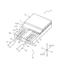
- FIG. 3 is a diagram showing an ultrasonic transducer 11. In FIG. 3, for convenience of explanation, the position of the electric signal line 14 connected to the ultrasonic vibrator 11 is shown by a chain double-dashed line.
- FIG. 4 is a diagram showing the back surface of the piezoelectric element 1 in the ultrasonic oscillator 11 shown in FIG.
- FIG. 5 is an exploded perspective view of the ultrasonic vibrator 11 shown in FIG. Also in FIG.
- FIG. 5 is a diagram showing a region where the piezoelectric element 1 and the support member 2 overlap in the thickness direction B in the ultrasonic vibrator 11 shown in FIG.
- the diagnostic imaging catheter 110 is applied to an intravascular ultrasound (abbreviated as "IVUS"). As shown in FIG. 1, the diagnostic imaging catheter 110 is driven by being connected to an external device 120. More specifically, the diagnostic imaging catheter 110 of the present embodiment is connected to the drive unit 120a of the external device 120.
- IVUS intravascular ultrasound
- the side inserted into the living body in the longitudinal direction A of the diagnostic imaging catheter 110 is described as the "tip side", and the opposite side is described as the "base end side”. To do. Further, the direction from the proximal end side to the distal end side of the diagnostic imaging catheter 110 may be simply described as "insertion direction A1". Further, the direction from the distal end side to the proximal end side of the diagnostic imaging catheter 110 may be simply described as "removal direction A2".
- the diagnostic imaging catheter 110 includes an insertion portion 110a and an operation portion 110b.
- the insertion portion 110a is a portion of the diagnostic imaging catheter 110 that is inserted into the living body and used.
- the operation unit 110b is a portion of the diagnostic imaging catheter 110 that is operated in vitro with the insertion unit 110a inserted into the living body.
- the portion on the distal end side of the distal end side connector 42 (see FIG. 1) described later is the insertion portion 110a
- the portion on the proximal end side from the distal end side connector 42 is the operation portion 110b. is there.
- the insertion portion 110a includes an ultrasonic probe 10 and a sheath 20.
- the operation unit 110b includes an inner pipe member 30 and an outer pipe member 40.
- the inner tube member 30 holds an end portion of the ultrasonic probe 10 on the proximal end side.
- the outer tube member 40 holds an end portion of the sheath 20 on the base end side.
- the ultrasonic probe 10 can move in the sheath 20 in the longitudinal direction A by moving the inner tube member 30 in the outer tube member 40 in the central axis direction.
- the drive shaft 13 and the electric signal line 14 which are a part of the ultrasonic probe 10 pass through the inside of the inner tube member 30 and the outer tube member 40, and the insertion portion 110a is inserted in the longitudinal direction A. It extends not only to the region of the above but also to the region of the operation unit 110b. That is, the operation unit 110b of the present embodiment is partially composed of the ultrasonic probe 10 in addition to the inner tube member 30 and the outer tube member 40.
- the ultrasonic probe 10 includes an ultrasonic oscillator 11, a housing 12, a drive shaft 13, and an electric signal line 14.
- the ultrasonic vibrator 11 includes a piezoelectric element 1, a support member 2, and an acoustic matching member 3.
- the piezoelectric element 1 includes a flat piezoelectric body 4, a first electrode 5 laminated on at least one side of the piezoelectric body 4 in the thickness direction B, and at least the other of the piezoelectric body 4 in the thickness direction B. It is composed of a second electrode 6 laminated on the side.
- the surface side of the piezoelectric element 1 one side of the thickness direction B of the piezoelectric body 4 in which at least a part of the first electrode 5 is provided.
- the other side of the piezoelectric body 4 in the thickness direction B in which at least a part of the second electrode 6 is provided is described as "the back surface side of the piezoelectric element 1".
- the surface side of the piezoelectric element 1 is a side that transmits and receives ultrasonic waves. Further, the back surface side of the piezoelectric element 1 is the side opposite to the side that transmits and receives ultrasonic waves.
- the piezoelectric body 4 of the piezoelectric element 1 is composed of, for example, a piezoelectric ceramic sheet.
- Examples of the material of the piezoelectric ceramic sheet include piezoelectric ceramic materials such as lead titanate (PZT) and lithium niobate.
- the piezoelectric body 4 may be made of crystal instead of the piezoelectric ceramic material.
- the first electrode 5 and the second electrode 6 of the piezoelectric element 1 are laminated as electrode layers on both sides of the piezoelectric body 4 in the thickness direction B by, for example, an ion plating method using a mask material, a vapor deposition method, or a sputtering method.
- an ion plating method using a mask material e.g., aluminum, copper, nickel, and gold.
- the material of the first electrode 5 and the second electrode 6 include metals such as silver, chromium, copper, nickel, and gold, and laminates of these metals.
- the second electrode 6 of the present embodiment is formed only on the back surface side of the piezoelectric element 1.
- the first electrode 5 of the present embodiment is composed of a folded electrode.
- the first electrode 5 of the present embodiment includes a front electrode layer 5a, a back electrode layer 5b, and a connecting conductive portion 5c.
- the surface electrode layer 5a is located on the surface side of the piezoelectric element 1.
- the back surface electrode layer 5b is located on the back surface side of the piezoelectric element 1.
- the connecting conductive portion 5c connects the front surface electrode layer 5a and the back surface electrode layer 5b.
- the first electrode 5 of the present embodiment is formed from the front surface side to the back surface side of the piezoelectric element 1.
- the back electrode layer 5b of the first electrode 5 and the second electrode 6 can be arranged together on the back surface side of the piezoelectric element 1.
- the connection work between the electric signal line 14, the first electrode 5, and the second electrode 6 is performed in a piezoelectric manner, as compared with the case where the first electrode and the second electrode are arranged only on separate surfaces of the piezoelectric element. This can be done only on one side of the element 1.
- the piezoelectric element 1 has a thickness direction B, a first portion 1a composed of a portion overlapping the first terminal 7 and a portion overlapping the second terminal 8 of the support member 2 described later, and a thickness direction.
- B includes a second portion 1b excluding the first portion 1a. The details will be described later.
- the outer shape of the piezoelectric element 1 is preferably square as in the present embodiment rather than rectangular. .. By doing so, the straightness of the ultrasonic wave can be improved. Therefore, as shown in FIG. 6, it is preferable that the lengths (vertical direction in FIG. 6) and horizontal (horizontal direction in FIG. 6) of the piezoelectric element 1 are substantially equal. Further, in the case of a small ultrasonic transducer 11 used in a blood vessel, it is preferable to increase the output of ultrasonic waves.
- the piezoelectric element 1 has a square outer shape in a plan view shown in FIG. 6, and the area of the second portion 1b of the piezoelectric element 1 is larger than the area of the first portion 1a of the piezoelectric element 1. Is preferable.
- the support member 2 supports the piezoelectric element 1. Further, as shown in FIGS. 3 and 5, the support member 2 is connected to the first terminal 7 connected to the first electrode 5 of the piezoelectric element 1 and the second electrode 6 of the piezoelectric element 1. It includes two terminals 8. Further, as shown in FIG. 3, the first terminal 7 and the second terminal 8 include a portion that does not overlap with the piezoelectric element 1 in the thickness direction B. By providing such a first terminal 7 and a second terminal 8, the electrical contact point between the first electrode 5 and the second electrode 6 of the piezoelectric element 1 can be pulled out to the outside of the piezoelectric element 1.
- the support member 2 of the present embodiment supports the piezoelectric element 1 from the back surface side of the piezoelectric element 1.
- the support member 2 is laminated on the back surface side of the piezoelectric element 1 so as to cover the back surface side of the piezoelectric element 1.
- Examples of the material of the first terminal 7 and the second terminal 8 include metals such as silver, chromium, copper, nickel, and gold, and laminates of these metals.
- the support member 2 of the present embodiment includes a support main body 9 laminated on the back surface side of the piezoelectric element 1.
- the support main body 9 covers at least the entire back surface side of the piezoelectric body 4 of the piezoelectric element 1.
- the support main body 9 of the present embodiment covers the entire area on the back surface side of the piezoelectric element 1. More specifically, the support main body 9 of the present embodiment extends to the outside of the piezoelectric element 1 in the direction C (hereinafter, referred to as "in-plane direction C") orthogonal to the thickness direction B of the piezoelectric element 1. Exists.
- the first terminal 7 and the second terminal 8 of the present embodiment are supported by the support main body portion 9.
- the support main body 9 of the support member 2 is a sound absorber composed of, for example, rubber or an epoxy resin in which a metal powder such as tungsten powder is dispersed.
- the support main body 9 of the support member 2 can absorb the ultrasonic waves from the piezoelectric element 1 that become noise. That is, the support member 2 of the present embodiment constitutes a sound absorbing layer that absorbs the ultrasonic waves of the piezoelectric element 1.
- a method in which the first terminal 7 and the second terminal 8 are arranged in advance on the sheet material forming the support main body portion 9 and the sheet material is bonded to the piezoelectric element 1 or the like. Can be formed by.
- the first terminal 7 and the second terminal 8 may be formed by laminating the sheet material forming the support main body 9 by, for example, an ion plating method using a mask material, a vapor deposition method, or a sputtering method.
- the manufacturing method is not particularly limited.
- the terminal members forming the first terminal 7 and the second terminal 8 may be bonded to the support main body 9 by adhesion or the like.
- the first terminal 7 of the present embodiment is connected between the piezoelectric element 1 and the support main body 9 to the back surface electrode layer 5b of the first electrode 5.
- the piezoelectric element 1 and the support member 2 of the present embodiment are laminated so that the back electrode layer 5b of the first electrode 5 and the first terminal 7 face each other.
- the first terminal 7 of the present embodiment extends from the position between the piezoelectric element 1 and the support main body 9 to the outside of the piezoelectric element 1 in the in-plane direction C.
- the first terminal 7 is a piezoelectric element in the thickness direction B on the surface of the support main body 9 on the piezoelectric element 1 side in the thickness direction B (hereinafter, referred to as “upper surface of the support main body 9”). It is pulled out to a position that does not overlap with 1.
- the second terminal 8 of the present embodiment is connected to the second electrode 6 between the piezoelectric element 1 and the support main body portion 9.
- the piezoelectric element 1 and the support member 2 of the present embodiment are laminated so that the second electrode 6 and the second terminal 8 face each other.
- the second terminal 8 of the present embodiment extends from the position between the piezoelectric element 1 and the support main body 9 to the outside of the piezoelectric element 1 in the in-plane direction C. In other words, the second terminal 8 is pulled out on the upper surface of the support main body 9 to a position where it does not overlap with the piezoelectric element 1 in the thickness direction B.
- the first electrode 5 and the second electrode 6 of the piezoelectric element 1 are connected to the first terminal 7 and the second terminal 8 of the support member 2 on the back surface side of the piezoelectric element 1. Therefore, it is not necessary to secure a connection point of the electric signal line 14 on the surface side of the piezoelectric element 1 that transmits and receives ultrasonic waves, and when the electric signal line 14 is connected, the ultrasonic waves of the ultrasonic vibrator 11 are transmitted and received. It is possible to prevent the portion of the piezoelectric element 1 on the surface side from being damaged.
- the first terminal 7 and the second terminal 8 are visible from the surface side of the piezoelectric element 1. Therefore, the work of connecting the electric signal line 14 to the first terminal 7 and the second terminal 8 can be executed while visually monitoring the connection points and the like. As a result, it is possible to suppress the occurrence of defective products due to poor connection.
- the first terminal 7 and the second terminal 8 of the present embodiment are pulled out from a position overlapping the piezoelectric element 1 in the thickness direction B toward the proximal end side in the longitudinal direction A in the diagnostic imaging catheter 110. .. Therefore, of the first terminal 7 and the second terminal 8 of the present embodiment, the portion that does not overlap with the piezoelectric element 1 in the thickness direction B is provided on the proximal end side with respect to the piezoelectric element 1. As a result, as shown in FIG. 2, the first terminal 7 and the second terminal 8 of the present embodiment can easily be formed with the tip portion 14a of the electric signal line 14 extending from the tip end of the drive shaft 13 into the housing 12. You can connect.
- the first terminal 7 and the second terminal 8 of the present embodiment extend to the peripheral edge of the support member 2 in the in-plane direction C. More specifically, the first terminal 7 and the second terminal 8 of the present embodiment extend to a position where they are flush with the end surface of the support main body 9 in the in-plane direction C. By doing so, the electric signal line 14 can be more easily connected to the first terminal 7 and the second terminal 8 from the outside of the ultrasonic transducer 11.
- two groove portions 9a are partitioned on the upper surface of the support main body portion 9 facing the back surface of the piezoelectric element 1.
- the cross section of the groove portion 9a of the present embodiment is rectangular, but it may have another cross section shape such as a V shape or an arc shape.
- the first terminal 7 and the second terminal 8 of the present embodiment are arranged in the groove portion 9a of the support main body portion 9. Further, the upper surface of the first terminal 7 and the upper surface of the second terminal 8 facing the back surface of the piezoelectric element 1 are arranged so as to be flush with the upper surface of the support main body 9.
- the first electrode 5 and the second electrode 6 of the piezoelectric element 1 and the first terminal 7 and the second terminal 8 of the support member 2 are brought into contact with each other.
- the position stability of the piezoelectric element 1 on the support member 2 can be improved.
- the first electrode 5 and the second electrode 6 of the piezoelectric element 1 and the first terminal 7 and the second terminal 8 of the support member 2 are connected by using a conductive adhesive or the like.
- the upper surface of the first terminal 7 and the upper surface of the second terminal 8 facing the back surface of the piezoelectric element 1 may not protrude from the upper surface of the support main body portion 9 and may be arranged in the groove portion 9a.
- a conductive material such as the above-mentioned conductive adhesive is placed between the first electrode 5 and the second electrode 6 of the piezoelectric element 1 and the first terminal 7 and the second terminal 8 of the support member 2. It may be filled with.
- the first terminal 7 of the present embodiment partitions the groove portion 7a accommodating the electric signal line 14. Since the first terminal 7 partitions such a groove portion 7a, the electric signal line 14 can be connected to the first terminal 7 in a state where the electric signal line 14 is positioned in the groove portion 7a. Therefore, the efficiency of the connection work between the electric signal line 14 and the first terminal 7 is improved.
- the second terminal 8 of the present embodiment also has a groove portion 8a for accommodating the electric signal line 14.
- the electric signal line 14 can be connected to the second terminal 8 in a state where the electric signal line 14 is positioned in the groove 8a. Therefore, the efficiency of the connection work between the electric signal line 14 and the second terminal 8 is improved.
- the electric signal line 14 can be connected to each terminal (first terminal 7, second terminal in this embodiment). It becomes easy to connect to 8).
- the cross-sectional shape of the groove portion 7a and the groove portion 8a of the present embodiment is rectangular, but a groove portion having a cross-sectional shape such as a V-shape or an arc shape may be used. Further, it is preferable that the groove portion 7a and the groove portion 8a also extend to a position where they are flush with the end surface of the support main body portion 9 in the in-plane direction C. By doing so, it becomes easier to position the electric signal line 14.
- FIG. 7 is a diagram showing an outline of a process of connecting the electric signal line 14 to the first terminal 7.
- a connecting portion 14a made of a conducting wire from which the covering material has been removed is formed at the end of the electric signal wire 14.
- the groove portion 7a of the first terminal 7 is filled with the solder paste 205.
- the groove portion 7a may be filled with preliminary solder.
- the connecting portion 14a of the electric signal line 14 is arranged on the solder paste 205 filled in the groove portion 7a of the first terminal 7. It may be buried in the solder paste 205 filled in the groove 7a.
- Preliminary solder or solder paste may be further applied so as to sandwich the connection portion 14a with the solder paste 205.
- the solder paste 205 and the preliminary solder are melted by heating with hot air, and the connecting portion 14a is connected to the first terminal 7 in the groove portion 7a. In this way, the electric signal line 14 can be connected to the first terminal 7.
- connection method between the electric signal line 14 and the first terminal 7 is shown, but the same applies to the connection method between the electric signal line 14 and the second terminal 8.
- the piezoelectric element 1 includes a first portion 1a composed of a portion overlapping the first terminal 7 and a portion overlapping the second terminal 8 in the thickness direction B, and a second portion 1b excluding the first portion 1a. , (See FIG. 6).
- the entire area on the back surface side of the second portion 1b of the piezoelectric element 1 is covered with the support main body portion 9.
- the support main body portion 9 is arranged over the entire back surface of the second portion 1b, which is a mainly vibrating portion of the piezoelectric element 1. Therefore, the ultrasonic wave from the piezoelectric element 1 which becomes noise can be more reliably absorbed by the support main body portion 9.
- the acoustic matching member 3 is laminated so as to cover a part of the surface side of the piezoelectric element 1. More specifically, the acoustic matching member 3 of the present embodiment is laminated so as to cover most of the surface side (for example, 80% or more) of the second portion 1b of the piezoelectric element 1, but the present invention is not limited to this configuration. , The second portion 1b of the piezoelectric element 1 may be laminated so as to cover the entire surface side. Further, the piezoelectric element 1 may be laminated so as to cover the surface side of both the first portion 1a and the second portion 1b, or may be laminated so as to cover the entire surface side of the piezoelectric element 1.
- the acoustic matching member 3 of the present embodiment constitutes an acoustic matching layer that enhances the propagation efficiency of ultrasonic waves.
- the acoustic matching layer as the acoustic matching member 3 is formed by a method in which a sheet material forming the acoustic matching layer is attached to the piezoelectric element 1, a method in which a liquid acoustic matching material forming the acoustic matching layer is applied and cured, and the like. Can be formed.
- the material of the acoustic matching member 3 include a resin material such as an epoxy resin.
- the acoustic matching member 3 may be composed of a laminate of resin layers made of a resin material.
- the housing 12 houses the ultrasonic oscillator 11 inside.
- the base end side of the housing 12 is connected to the drive shaft 13.
- the housing 12 has a shape in which an opening 12a is provided in a part of the peripheral wall of a cylindrical metal pipe in which both ends in the axial direction are closed, and is machined from a metal block or MIM (metal powder injection). It is formed by molding) or the like.
- the housing 12 of the present embodiment includes a tip wall portion 12b located on the tip side of the above-mentioned opening 12a and a base end wall portion 12c located on the base end side of the above-mentioned opening 12a. , Equipped with.
- both ends in the axial direction are closed by the tip wall portion 12b and the base end wall portion 12c.
- the drive shaft 13 is made of a flexible tubular body. Inside the drive shaft 13, an electric signal line 14 connected to the ultrasonic transducer 11 is arranged.
- the drive shaft 13 is composed of, for example, a multi-layer coil having different winding directions around the shaft. Examples of the coil material include stainless steel and Ni—Ti (nickel / titanium) alloy.
- the drive shaft 13 passes through the inside of the inner pipe member 30 and the outer pipe member 40 and extends to the hub 32 described later located at the base end portion of the inner pipe member 30. That is, the drive shaft 13 extends from the tip end portion of the insertion portion 110a to the base end portion of the operation portion 110b in the longitudinal direction A.
- the electric signal line 14 extends in the drive shaft 13 and electrically connects the ultrasonic vibrator 11 and the external device 120. That is, like the drive shaft 13, the electric signal line 14 extends from the tip end portion of the insertion portion 110a to the base end portion of the operation portion 110b in the longitudinal direction A.
- a plurality of electric signal lines 14 are provided, and each electric signal line 14 is provided via the first terminal 7 or the second terminal 8 of the support member 2 described above, and the piezoelectric element 1 described above is provided. It is connected to the first electrode 5 or the second electrode 6 of the above.
- the plurality of electric signal lines 14 are composed of, for example, a twisted pair cable in which two electric signal lines 14 are twisted together.
- Each electric signal line 14 can be a flexible thin wire member having an outer diameter of more than 0 mm and 0.1 mm or less.
- Each electric signal line 14 can be composed of, for example, a lead wire larger than 0 mm and 0.05 mm or less, and a covering material formed of an insulating material and covering the periphery of the lead wire.
- Such an electric signal line 14 is connected to the piezoelectric element 1 by a connecting portion 14a (see FIGS. 3 and 5) formed of a conducting wire whose covering material is removed and exposed.
- the connecting portion 14a of the two electric signal lines 14 is connected to the first terminal 7 and the second terminal 8 of the support member 2 by using solder, a conductive adhesive, or the like (see FIG. 7). ).
- the two electric signal lines 14 are electrically connected to the first electrode 5 and the second electrode 6 of the piezoelectric element 1 via the first terminal 7 and the second terminal 8 of the support member 2. More specifically, the two electric signal lines 14 are connected to the first terminal 7 and the second terminal 8 of the support member 2 on the distal end side of the base end wall portion 12c of the housing 12.
- the sheath 20 partitions the first hollow portion 21a and the second hollow portion 21b.
- the ultrasonic probe 10 is housed in the first hollow portion 21a.
- the ultrasonic probe 10 can move back and forth in the longitudinal direction A in the first hollow portion 21a.
- a guide wire W can be inserted into the second hollow portion 21b.
- the tubular guide wire insertion portion 20b that partitions the second hollow portion 21b is parallel to the tip of the tubular main body portion 20a that partitions the first hollow portion 21a. Is located in.
- the main body portion 20a and the guide wire insertion portion 20b can be formed by joining different pipe members by heat fusion or the like, but the forming method is not limited to this.
- the main body 20a is provided with a marker 22 having X-ray contrast property, which is formed of a material that is opaque to X-rays. Further, the guide wire insertion portion 20b is also provided with a marker 23 having X-ray contrast property.
- the markers 22 and 23 can be configured by, for example, a metal coil having high X-ray opacity such as platinum, gold, iridium, and tungsten.
- a window portion 24 formed in which the transparency of ultrasonic waves is higher than that of other parts is formed. More specifically, the window portion 24 of the present embodiment is formed on the main body portion 20a of the sheath 20.
- the window portion 24 of the main body portion 20a and the guide wire insertion portion 20b are formed of a flexible material, and the material is not particularly limited.
- the constituent material include various thermoplastic elastomers such as polyethylene, styrene, polyolefin, polyurethane, polyester, polyamide, polyimide, polybutadiene, transpolyisoprene, fluororubber, and chlorinated polyethylene, and one of them.
- a polymer alloy, a polymer blend, a laminate, or the like in which two or more kinds are combined can also be used.
- the base end side of the main body portion 20a with respect to the window portion 24 has a reinforcing portion reinforced with a material having a higher rigidity than the window portion 24.
- the reinforcing portion is formed, for example, by disposing a reinforcing material in which a metal wire such as stainless steel is braided in a mesh shape on a flexible tubular member such as resin.
- the tubular member is made of the same material as the window portion 24.
- hydrophilic lubricating coating layer that exhibits lubricity when wet on the outer surface of the sheath 20.
- a communication hole 26 for communicating the inside and the outside of the first hollow portion 21a is formed. At the time of priming, the gas in the main body 20a can be discharged through the communication hole 26.
- the inner pipe member 30 includes an inner pipe 31 and a hub 32.
- the inner pipe 31 is inserted so as to be movable back and forth in the outer pipe member 40.
- the hub 32 is provided on the base end side of the inner pipe 31.
- the outer tube member 40 includes an outer tube 41, a tip end side connector 42, and a proximal end side connector 43.
- the outer pipe 41 is located on the outer side in the radial direction of the inner pipe 31, and the inner pipe 31 moves back and forth inside the outer pipe 41.
- the tip-side connector 42 connects the base end of the main body 20a of the sheath 20 and the tip of the outer tube 41.
- the base end side connector 43 is provided at the base end portion of the outer pipe 41, and is configured to receive the inner pipe 31 in the outer pipe 41.
- the drive shaft 13 and the electric signal line 14 of the ultrasonic probe 10 described above are the main body 20a of the sheath 20, the outer tube member 40 connected to the proximal end side of the main body 20a, and the outer tube member 40. It extends to the hub 32 located at the base end of the inner pipe member 30 in which a part of the inner pipe member 30 is inserted.
- the ultrasonic probe 10 and the inner tube member 30 described above are connected to each other so as to move back and forth in the longitudinal direction A integrally. Therefore, for example, when the inner pipe member 30 is pushed in the insertion direction A1, the inner pipe member 30 is pushed into the outer pipe member 40 in the insertion direction A1. When the inner tube member 30 is pushed into the outer tube member 40 toward the insertion direction A1, the ultrasonic probe 10 connected to the inner tube member 30 moves in the main body 20a of the sheath 20 in the insertion direction A1. To do. On the contrary, when the inner pipe member 30 is pulled in the pulling direction A2, the inner pipe member 30 is pulled out from the outer pipe member 40 in the pulling direction A2. When the inner tube member 30 is pulled out from the inside of the outer tube member 40 in the removal direction A2, the ultrasonic probe 10 connected to the inner tube member 30 moves in the main body 20a of the sheath 20 in the removal direction A2.
- the tip portion of the inner pipe member 30 reaches the vicinity of the tip side connector 42 of the outer pipe member 40.
- the ultrasonic transducer 11 of the ultrasonic probe 10 is located near the tip of the main body 20a of the sheath 20.
- the inner pipe member 30 is prevented from popping out toward the tip side of the outer pipe member 40, and the outer pipe member 40 is pulled to the most proximal side when the inner pipe member 30 is pulled to the most proximal side.
- a stopper is provided on the base end side of the tube to prevent it from falling off.
- the stopper portion is not particularly limited as long as it can realize the above function, and may be configured by, for example, a wall portion that abuts the outer pipe member 40 at a predetermined position in the longitudinal direction A.
- a connector portion that is mechanically and electrically connected to the external device 120 is provided at the base end of the hub 32 of the inner pipe member 30. That is, the diagnostic imaging catheter 110 is mechanically and electrically connected to the external device 120 by a connector portion provided on the hub 32 of the inner tube member 30. More specifically, the electric signal line 14 of the ultrasonic probe 10 extends from the ultrasonic transducer 11 to the connector portion of the hub 32, and the connector portion of the hub 32 is connected to the external device 120. Then, the ultrasonic vibrator 11 and the external device 120 are electrically connected. The received signal in the ultrasonic vibrator 11 is transmitted to the external device 120 via the connector portion of the hub 32, is subjected to predetermined processing, and is displayed as an image.
- the external device 120 has a motor 121 which is a power source for rotating the drive shaft 13 and a motor 122 which is a power source for moving the drive shaft 13 in the longitudinal direction A. ..
- the rotational motion of the motor 122 is converted into axial motion by the ball screw 123 connected to the motor 122.
- the external device 120 of the present embodiment includes a drive unit 120a, a control device 120b electrically connected to the drive unit 120a by wire or wirelessly, and the control device 120b is a diagnostic imaging catheter 110.
- a monitor 120c capable of displaying an image generated based on a received signal received from is provided.
- the above-mentioned motor 121, motor 122 and ball screw 123 of the present embodiment are provided in the drive unit 120a.
- the operation of the drive unit 120a is controlled by the control device 120b.
- the control device 120b can be configured by a processor including a CPU and a memory.
- the external device 120 is not limited to the configuration shown in the present embodiment, and may be further provided with an external input unit such as a keyboard, for example.
- the ultrasonic oscillator according to the present disclosure is not limited to the specific configuration specified in the above-described embodiment, and can be variously modified or changed as long as it does not deviate from the description of the claims.
- the first electrode 5 is composed of a folded electrode, but neither the first electrode 5 nor the second electrode 6 is a folded electrode, and each is laminated on only one side. It may be a configuration.
- the second electrode 6 may be composed of a folded electrode.
- the first electrode 5 and the second electrode 6 of the piezoelectric element 1 are on the back surface side of the piezoelectric element 1 and the support member 2 is the first. It is connected to the 1st terminal 7 and the 2nd terminal 8. Therefore, as described above, it is not necessary to secure a connection point for the electric signal line 14 on the surface side of the piezoelectric element 1 that transmits and receives ultrasonic waves, and when connecting the electric signal line 14, the ultrasonic vibrator 11 It is possible to prevent damage to the surface side portion of the piezoelectric element 1 that transmits and receives ultrasonic waves.
- the ultrasonic probe to which the ultrasonic transducer according to the present disclosure can be applied is not limited to the configuration of the ultrasonic probe 10 shown in the above-described embodiment.
- the ultrasonic probe 10 of the above-described embodiment has a configuration in which only an ultrasonic transducer 11 capable of intravascular ultrasonic diagnosis is provided as an imaging core, but the configuration is not limited to this configuration, and for example, an optical interference fault. It may be configured to further include an optical transmission / reception unit that enables diagnosis (Optical Coherence Tomography, abbreviated as “OCT”).
- OCT optical Coherence Tomography
- FIG. 8 is a cross-sectional view showing a part of an image diagnostic catheter 410 including an ultrasonic transducer 11 and an ultrasonic probe 310 including an optical transmission / reception unit 301.
- the ultrasonic probe 310 shown in FIG. 8 is different from the above-mentioned ultrasonic probe 10 in that a configuration that enables optical interference tomographic diagnosis is added.
- an optical transmitter / receiver 301 is arranged in the housing 12 in addition to the ultrasonic oscillator 11.
- the optical transmission / reception unit 301 continuously transmits light (measurement light) transmitted from the optical fiber cable as the optical signal line 302 extending in the drive shaft 13 into the biological lumen, and also in the biological lumen. Continuously receives reflected light from the living body tissue of.
- the optical transmission / reception unit 301 transmits the received reflected light to the external device 120 (see FIG. 1) through the optical signal line 302.
- the control device 120b (see FIG. 1) of the external device 120 generates interference light data by interfering the reflected light obtained by the measurement with the reference light obtained by separating the light from the light source. Further, the control device 120b of the external device 120 generates an optical tomographic image based on the generated interference light data and displays it on the monitor 120c (see FIG. 1).
- the plurality of electric signal lines 14 are spirally wound around the optical signal line 302, and the plurality of electric signal lines 14 extend in parallel with each other. .. More specifically, the two electric signal lines 14 shown in FIG. 8 extend around the optical fiber cable as the optical signal line 302 extending in the longitudinal direction A in a double spiral shape.
- This disclosure relates to an ultrasonic oscillator.
Landscapes
- Health & Medical Sciences (AREA)
- Life Sciences & Earth Sciences (AREA)
- Engineering & Computer Science (AREA)
- Medical Informatics (AREA)
- Surgery (AREA)
- Pathology (AREA)
- Radiology & Medical Imaging (AREA)
- Biophysics (AREA)
- Biomedical Technology (AREA)
- Heart & Thoracic Surgery (AREA)
- Physics & Mathematics (AREA)
- Molecular Biology (AREA)
- Nuclear Medicine, Radiotherapy & Molecular Imaging (AREA)
- Animal Behavior & Ethology (AREA)
- General Health & Medical Sciences (AREA)
- Public Health (AREA)
- Veterinary Medicine (AREA)
- Mechanical Engineering (AREA)
- Gynecology & Obstetrics (AREA)
- Ultra Sonic Daignosis Equipment (AREA)
Abstract
本開示に係る超音波振動子は、圧電素子と、前記圧電素子を支持する支持部材と、を備える超音波振動子であって、前記圧電素子は、扁平状の圧電体と、前記圧電体の厚み方向の少なくとも一方側に積層されている第1電極と、前記圧電体の前記厚み方向の少なくとも他方側に積層されている第2電極と、からなり、前記支持部材は、前記圧電素子の前記第1電極と接続されている第1端子と、前記圧電素子の前記第2電極に接続されている第2端子と、を備え、前記第1端子及び前記第2端子は、前記厚み方向で前記圧電素子と重ならない部分を備える。
Description
本開示は超音波振動子に関する。
超音波振動子を含む超音波探触子は、医療用超音波診断装置の超音波の送受信器として利用されている。最近では、カテーテルに超音波探触子を装填して、カテーテルを体内に挿入した状態で超音波診断をすることが行なわれている。
特許文献1には、頂部主表面及び底部主表面を有するアクティブトランスジューサエレメントと、頂部主表面上に形成される頂部電極と、底部主表面上に形成される底部電極と、底部電極を覆う導電性バッキングエレメントと、頂部電極に電気的に接続されている第1リードと、導電性バッキングエレメントに電気的に接続される第2リードと、を備える超音波探触子が開示されている。
カテーテルに装填される超音波探触子では、患者負担を軽減するため、及び、血管深部などのより細径な体腔への挿入性を高めるため、小型化の要求が高い。
超音波探触子の小型化は、圧電体及び一対の電極からなる圧電素子を含む超音波振動子を小型化することで実現できる。しかしながら、超音波振動子を小型化すると、圧電素子も小さくなる。そのため、圧電素子の電極も小さくなり、圧電素子と外部電源とを接続する電気信号線を、圧電素子の電極に接続する作業が困難になる。
本開示は、圧電素子に対して電気信号線を接続することが容易となる構成を備える超音波振動子を提供することを目的とする。
本開示の第1の態様としての超音波振動子は、圧電素子と、前記圧電素子を支持する支持部材と、を備える超音波振動子であって、前記圧電素子は、扁平状の圧電体と、前記圧電体の厚み方向の少なくとも一方側に積層されている第1電極と、前記圧電体の前記厚み方向の少なくとも他方側に積層されている第2電極と、からなり、前記支持部材は、前記圧電素子の前記第1電極と接続されている第1端子と、前記圧電素子の前記第2電極に接続されている第2端子と、を備え、前記第1端子及び前記第2端子は、前記厚み方向で前記圧電素子と重ならない部分を備える。
本開示の1つの実施形態として、前記支持部材は、前記厚み方向の前記他方側で前記圧電素子に積層され、前記厚み方向と直交する方向において前記圧電素子よりも外側まで延在している支持本体部を備え、前記第1端子及び前記第2端子は前記支持本体部に支持されている。
本開示の1つの実施形態として、前記圧電素子の前記第1電極は、前記圧電体の前記厚み方向の前記一方側に位置する表面電極層と、前記圧電体の前記厚み方向の前記他方側に位置する裏面電極層と、前記表面電極層及び前記裏面電極層を連結する連結導電部と、を備える。
本開示の1つの実施形態として、前記第1端子は、前記圧電素子と前記支持本体部との間で、前記第1電極の前記裏面電極層に接続されている。
本開示の1つの実施形態として、前記第2端子は、前記圧電素子と前記支持本体部との間で、前記第2電極に接続されている。
本開示の1つの実施形態として、前記圧電素子は、前記厚み方向で前記第1端子と重なる部分及び前記第2端子と重なる部分から成る第1部分と、前記第1部分を除く第2部分と、を備え、前記第2部分の前記厚み方向の前記他方側の全域は、前記支持本体部に覆われている。
本開示によれば、圧電素子に対して電気信号線を接続することが容易となる構成を備える超音波振動子を提供することができる。
以下、本開示に係る超音波振動子の実施形態について図面を参照して説明する。各図において共通する部材・部位には同一の符号を付している。
まず、本開示に係る超音波振動子を適用可能な画像診断装置の一例を説明する。図1は、一実施形態としての超音波振動子11を備える画像診断装置100を示す図である。
画像診断装置100は、画像診断用カテーテル110と、外部装置120と、を備える。図1では、画像診断用カテーテル110が外部装置120に接続されている状態を示している。図2は、画像診断用カテーテル110の先端部における長手方向Aに平行な断面を示す断面図である。図3は、超音波振動子11を示す図である。図3では、説明の便宜上、超音波振動子11に接続される電気信号線14の位置を二点鎖線により示している。図4は、図3に示す超音波振動子11における圧電素子1の裏面を示す図である。図5は、図3に示す超音波振動子11の分解斜視図である。図5においても、説明の便宜上、超音波振動子11に接続される電気信号線14の位置を二点鎖線により示している。また、図5では、説明の便宜上、圧電素子1の第1電極5の裏面電極層5bの位置、及び、第2電極6の位置を破線により示している。図6は、図3に示す超音波振動子11において、圧電素子1と支持部材2との厚み方向Bの重なる領域を示す図である。
<画像診断用カテーテル110>
画像診断用カテーテル110は、血管内超音波診断法(Intravascular Ultrasound、略称「IVUS」)に適用される。図1に示すように、画像診断用カテーテル110は、外部装置120に接続されることによって駆動される。より具体的に、本実施形態の画像診断用カテーテル110は、外部装置120の駆動ユニット120aに接続されている。
画像診断用カテーテル110は、血管内超音波診断法(Intravascular Ultrasound、略称「IVUS」)に適用される。図1に示すように、画像診断用カテーテル110は、外部装置120に接続されることによって駆動される。より具体的に、本実施形態の画像診断用カテーテル110は、外部装置120の駆動ユニット120aに接続されている。
以下、説明の便宜上、画像診断用カテーテル110において、画像診断用カテーテル110の長手方向Aで生体内に挿入される側を「先端側」と記載し、その反対側を「基端側」と記載する。また、画像診断用カテーテル110の基端側から先端側に向かう方向を単に「挿入方向A1」と記載する場合がある。また、画像診断用カテーテル110の先端側から基端側に向かう方向を単に「抜去方向A2」と記載する場合がある。
図1に示すように、画像診断用カテーテル110は、挿入部110aと、操作部110bと、を備える。挿入部110aは、画像診断用カテーテル110のうち、生体内に挿入されて使用される部位である。操作部110bは、画像診断用カテーテル110のうち、挿入部110aが生体内に挿入されている状態で、生体外で操作される部位である。本実施形態の画像診断用カテーテル110では、後述する先端側コネクタ42(図1参照)よりも先端側の部分が挿入部110aであり、先端側コネクタ42から基端側の部分が操作部110bである。
図1、図2に示すように、挿入部110aは、超音波探触子10と、シース20と、を備える。
図1に示すように、操作部110bは、内管部材30と、外管部材40と、を備える。内管部材30は、超音波探触子10の基端側の端部を保持している。外管部材40は、シース20の基端側の端部を保持している。詳細は後述するが、内管部材30が外管部材40内を中心軸方向に移動することで、超音波探触子10がシース20内を長手方向Aに移動することができる。また、詳細は後述するが、超音波探触子10の一部である駆動シャフト13及び電気信号線14は、内管部材30及び外管部材40の内部を通じて、長手方向Aにおいて、挿入部110aの領域のみならず、操作部110bの領域に亘って延在している。つまり、本実施形態の操作部110bは、内管部材30及び外管部材40に加えて、超音波探触子10により一部が構成されている。
[超音波探触子10]
図2に示すように、超音波探触子10は、超音波振動子11と、ハウジング12と、駆動シャフト13と、電気信号線14と、を備える。
図2に示すように、超音波探触子10は、超音波振動子11と、ハウジング12と、駆動シャフト13と、電気信号線14と、を備える。
図3に示すように、超音波振動子11は、圧電素子1と、支持部材2と、音響整合部材3と、を備える。具体的に、圧電素子1は、扁平状の圧電体4と、この圧電体4の厚み方向Bの少なくとも一方側に積層されている第1電極5と、圧電体4の厚み方向Bの少なくとも他方側に積層されている第2電極6と、からなる。以下、説明の便宜上、少なくとも第1電極5の一部が設けられている、圧電体4の厚み方向Bの一方側を「圧電素子1の表面側」と記載する。また、説明の便宜上、少なくとも第2電極6の一部が設けられている、圧電体4の厚み方向Bの他方側を「圧電素子1の裏面側」と記載する。圧電素子1の表面側とは、超音波の送受信を行う側である。また、圧電素子1の裏面側とは、超音波の送受信を行う側とは反対側である。
圧電素子1の圧電体4は、例えば、圧電セラミックシートにより構成される。圧電セラミックシートの材料としては、例えば、チタン酸ジルコニウム酸鉛(PZT)、ニオブ酸リチウムなどの圧電セラミック材料が挙げられる。圧電体4は、圧電セラミック材料ではなく、水晶により形成されていてもよい。
圧電素子1の第1電極5及び第2電極6は、例えば、マスク材を用いたイオンプレーティング法、蒸着法、スパッタ法により、圧電体4の厚み方向Bの両面それぞれに電極層として積層させることで形成できる。第1電極5及び第2電極6の材料としては、例えば、銀、クロム、銅、ニッケル、金などの金属や、これら金属の積層体などが挙げられる。
図3、図4に示すように、本実施形態の第2電極6は、圧電素子1の裏面側のみに形成されている。
これに対して、図3、図4に示すように、本実施形態の第1電極5は折返し電極により構成されている。具体的に、本実施形態の第1電極5は、表面電極層5aと、裏面電極層5bと、連結導電部5cと、を備える。表面電極層5aは、圧電素子1の表面側に位置する。裏面電極層5bは、圧電素子1の裏面側に位置する。連結導電部5cは、表面電極層5a及び裏面電極層5bを連結している。換言すれば、本実施形態の第1電極5は、圧電素子1の表面側から裏面側に亘って形成されている。第1電極5を折返し電極とすることで、圧電素子1の裏面側に、第1電極5の裏面電極層5b、及び、第2電極6、を共に配置できる。これにより、第1電極及び第2電極それぞれが圧電素子の別々の面のみに配置されている場合と比較して、電気信号線14と第1電極5及び第2電極6との接続作業を圧電素子1の片面側のみで行うことができるようになる。
また、図6に示すように、圧電素子1は、厚み方向Bで、後述する支持部材2の第1端子7と重なる部分及び第2端子8と重なる部分から成る第1部分1aと、厚み方向Bで、第1部分1aを除く第2部分1bと、を備える。この詳細は後述する。
また、図6に示すように、超音波振動子11を厚み方向Bで見た平面視において、圧電素子1の外形は、長方形とするよりも、本実施形態のように正方形とすることが好ましい。このようにすることで、超音波の直進性を高めることができる。したがって、図6に示すように、圧電素子1の縦(図6の上下方向)及び横(図6の左右方向)の長さを略等しくすることが好ましい。更に、血管内で使用される小型の超音波振動子11の場合には、超音波の出力を高めることが好ましい。そのため、圧電素子1の主に振動する部分である第2部分1bを大きく確保することが好ましい。以上のことから、圧電素子1は、図6に示す平面視で正方形の外形であり、かつ、圧電素子1の第2部分1bの面積は、圧電素子1の第1部分1aの面積よりも大きいことが好ましい。
図3に示すように、支持部材2は、圧電素子1を支持する。また、図3、図5に示すように、支持部材2は、圧電素子1の第1電極5と接続されている第1端子7と、圧電素子1の第2電極6に接続されている第2端子8と、を備える。また、図3に示すように、第1端子7及び第2端子8は、厚み方向Bで圧電素子1と重ならない部分を備える。このような第1端子7及び第2端子8を備えることで、圧電素子1の第1電極5及び第2電極6との電気接点を、圧電素子1の外側に引き出すことができる。そのため、例えば小型化された圧電素子1など、電気信号線14を圧電素子1の第1電極5及び第2電極6に直接接続することが困難な場合であっても、上述の第1端子7及び第2端子8を利用することで、圧電素子1に対して電気信号線14を電気的に接続することが容易となる。
図3に示すように、本実施形態の支持部材2は、圧電素子1の裏面側から圧電素子1を支持している。換言すれば、支持部材2は、圧電素子1の裏面側を覆うように、圧電素子1の裏面側に積層されている。
第1端子7及び第2端子8の材料としては、例えば、銀、クロム、銅、ニッケル、金などの金属や、これら金属の積層体などが挙げられる。
より具体的に、本実施形態の支持部材2は、圧電素子1の裏面側に積層されている支持本体部9を備える。支持本体部9は、圧電素子1の少なくとも圧電体4の裏面側の全域を覆っている。本実施形態の支持本体部9は、圧電素子1の裏面側の全域を覆っている。より具体的に、本実施形態の支持本体部9は、圧電素子1の厚み方向Bと直交する方向C(以下、「面内方向C」と記載する。)において圧電素子1よりも外側まで延在している。本実施形態の第1端子7及び第2端子8は、支持本体部9に支持されている。
支持部材2の支持本体部9は、例えば、ゴムや、タングステン粉末などの金属粉末を分散させたエポキシ樹脂など、により構成される吸音体である。支持部材2の支持本体部9により、ノイズとなる圧電素子1からの超音波を吸収することができる。つまり、本実施形態の支持部材2は、圧電素子1の超音波を吸収する吸音層を構成している。
支持部材2としての吸音層は、支持本体部9を形成するシート材上に、第1端子7及び第2端子8を予め配設しておき、このシート材を圧電素子1に張り合わせる方法などによって形成することができる。第1端子7及び第2端子8は、例えば、マスク材を用いたイオンプレーティング法、蒸着法、スパッタ法により、支持本体部9を形成するシート材に積層させて形成してもよく、その製法は特に限定されない。第1端子7及び第2端子8を形成する端子部材を支持本体部9に接着等して接合してもよい。
図3~図5に示すように、本実施形態の第1端子7は、圧電素子1と支持本体部9との間で、第1電極5の裏面電極層5bに接続されている。換言すれば、本実施形態の圧電素子1及び支持部材2は、第1電極5の裏面電極層5bと第1端子7とが対向するように積層されている。また、本実施形態の第1端子7は、圧電素子1と支持本体部9との間の位置から、面内方向Cにおいて圧電素子1よりも外側まで延在している。換言すれば、第1端子7は、支持本体部9の厚み方向Bの圧電素子1側の面(以下、「支持本体部9の上面」と記載する。)上で、厚み方向Bで圧電素子1と重ならない位置まで引き出されている。
図3~図5に示すように、本実施形態の第2端子8は、圧電素子1と支持本体部9との間で、第2電極6に接続されている。換言すれば、本実施形態の圧電素子1及び支持部材2は、第2電極6と第2端子8とが対向するように積層されている。また、本実施形態の第2端子8は、圧電素子1と支持本体部9との間の位置から、面内方向Cにおいて圧電素子1よりも外側まで延在している。換言すれば、第2端子8は、支持本体部9の上面上で、厚み方向Bで圧電素子1と重ならない位置まで引き出されている。
このように、圧電素子1の第1電極5及び第2電極6は、圧電素子1の裏面側で、支持部材2の第1端子7及び第2端子8に接続される。そのため、超音波の送受信を行う圧電素子1の表面側で、電気信号線14の接続箇所を確保しなくてよく、電気信号線14の接続に際して、超音波振動子11のうち超音波の送受信を行う圧電素子1の表面側の部分が破損することを抑制できる。また、第1端子7及び第2端子8を、圧電素子1と支持本体部9との間の位置から、面内方向Cにおいて圧電素子1よりも外側まで延在させることで、第1端子7及び第2端子8は、圧電素子1の表面側から視認可能な状態となる。そのため、電気信号線14を第1端子7及び第2端子8に接続する作業を、接続箇所を目視等で監視しながら、実行することができる。これにより、接続不良による不良品の発生を抑制できる。
また、本実施形態の第1端子7及び第2端子8は、画像診断用カテーテル110において、厚み方向Bで圧電素子1と重なる位置から、長手方向Aの基端側に向かって引き出されている。そのため、本実施形態の第1端子7及び第2端子8のうち、厚み方向Bで圧電素子1と重ならない部分は、圧電素子1に対して基端側に設けられている。これにより、図2に示すように、本実施形態の第1端子7及び第2端子8は、駆動シャフト13の先端からハウジング12内に延在する電気信号線14の先端部14aと、容易に接続することができる。
更に、図3に示すように、本実施形態の第1端子7及び第2端子8は、支持部材2の面内方向Cの周縁まで延在している。より具体的に、本実施形態の第1端子7及び第2端子8は、支持本体部9の面内方向Cの端面と面一となる位置まで延在している。このようにすることで、超音波振動子11の外部から電気信号線14を、より容易に第1端子7及び第2端子8に接続することができる。
また、本実施形態の支持部材2では、圧電素子1の裏面と対向する支持本体部9の上面に2つの溝部9aが区画されている。本実施形態の溝部9aの横断面は矩形状であるが、例えば、V字形状、円弧形状など、別の横断面形状であってもよい。本実施形態の第1端子7及び第2端子8は、支持本体部9の溝部9a内に配置されている。また、圧電素子1の裏面と対向する第1端子7の上面及び第2端子8の上面は、支持本体部9の上面と面一になるように配置されている。これにより、圧電素子1及び支持部材2を積層することで、圧電素子1の第1電極5及び第2電極6と、支持部材2の第1端子7及び第2端子8と、を接触させること可能になると共に、圧電素子1の支持部材2上での位置安定性を向上させることができる。圧電素子1の第1電極5及び第2電極6と、支持部材2の第1端子7及び第2端子8と、は導電性接着剤等を用いて接続される。
但し、圧電素子1の裏面と対向する第1端子7の上面及び第2端子8の上面は、支持本体部9の上面よりも突出せず、溝部9a内に配置されていてもよい。このような場合は、圧電素子1の第1電極5及び第2電極6と、支持部材2の第1端子7及び第2端子8と、の間を、上述の導電性接着剤等の導電材で充填すればよい。このようにすることで、第1端子7の上面、第2端子8の上面、及び、支持本体部9の上面を面一とすることによる上述の効果と同様の効果を得ることができる。
更に、図3、図5に示すように、本実施形態の第1端子7は、電気信号線14を収容する溝部7aを区画している。第1端子7がこのような溝部7aを区画していることで、電気信号線14を溝部7a内に位置決めした状態で、電気信号線14を第1端子7に接続することができる。そのため、電気信号線14と第1端子7との接続作業の効率が向上する。
また、図3、図5に示すように、本実施形態の第2端子8についても、電気信号線14を収容する溝部8aを区画している。第2端子8がこのような溝部8aを区画していることで、電気信号線14を溝部8a内に位置決めした状態で、電気信号線14を第2端子8に接続することができる。そのため、電気信号線14と第2端子8との接続作業の効率が向上する。
このように、第1端子7及び第2端子8に溝部(本実施形態では溝部7a、8a)を設けることで、電気信号線14を各端子(本実施形態では第1端子7、第2端子8)に接続し易くなる。本実施形態の溝部7a及び溝部8aの横断面形状は矩形状であるが、例えば、V字形状、円弧形状などの横断面形状を有する溝部としてもよい。また、溝部7a及び溝部8aについても、支持本体部9の面内方向Cの端面と面一となる位置まで延在していることが好ましい。このようにすることで、電気信号線14を、より位置決めし易くなる。
ここで、電気信号線14を第1端子7に接続する方法の一例を説明する。図7は、電気信号線14を第1端子7に接続する工程の概要を示す図である。まず、電気信号線14の端部に、被覆材が除去された導線からなる接続部14aを形成する。また、第1端子7の溝部7aにハンダペースト205を充填する。ハンダペースト205に代えて、予備はんだを溝部7aに充填してもよい。この状態で、電気信号線14の接続部14aを、第1端子7の溝部7aに充填されているハンダペースト205上に配置する。溝部7aに充填されているハンダペースト205内に埋没させてもよい。ハンダペースト205との間に接続部14aを挟み込むように、予備はんだやハンダペーストを更に塗布してもよい。次に、熱風で加熱することで、ハンダペースト205や予備はんだを溶融させ、接続部14aを溝部7a内で、第1端子7に接続する。このようにして、電気信号線14を第1端子7に接続することができる。
ここでは電気信号線14と第1端子7との接続方法を示したが、電気信号線14と第2端子8との接続方法についても同様である。
また、上述したように、圧電素子1は、厚み方向Bで第1端子7と重なる部分及び第2端子8と重なる部分から成る第1部分1aと、第1部分1aを除く第2部分1bと、を備える(図6参照)。図6に示すように、本実施形態では、圧電素子1の第2部分1bの裏面側の全域は、支持本体部9に覆われている。このような構成とすることで、圧電素子1の主に振動する部分である第2部分1bの裏面全域に支持本体部9が配置される。そのため、ノイズとなる圧電素子1からの超音波を、支持本体部9により、より確実に吸収することができる。
図3に示すように、音響整合部材3は、圧電素子1の表面側の一部を覆うように積層されている。より具体的に、本実施形態の音響整合部材3は、圧電素子1の第2部分1bの表面側の大部分(例えば80%以上)を覆うように積層されているが、この構成に限られず、圧電素子1の第2部分1bの表面側の全域を覆うように積層されていてもよい。また、圧電素子1の第1部分1a及び第2部分1bの両方の表面側を覆うように積層されていてもよく、圧電素子1の表面側の全域を覆うように積層されていてもよい。
音響整合部材3を設けることにより、被検体への超音波の伝播効率を高めることができる。つまり、本実施形態の音響整合部材3は、超音波の伝播効率を高める音響整合層を構成している。
音響整合部材3としての音響整合層は、音響整合層を形成するシート材を圧電素子1に張り合わせる方法、音響整合層を形成する液状の音響整合性材料を塗布して硬化させる方法、などによって形成することができる。音響整合部材3の材料としては、例えば、エポキシ樹脂などの樹脂材料が挙げられる。また、音響整合部材3は、樹脂材料から構成された樹脂層の積層体により構成されていてもよい。
図2に示すように、ハウジング12は、超音波振動子11を内部に収容している。ハウジング12の基端側は、駆動シャフト13に接続されている。ハウジング12は、軸方向の両端部が閉鎖されている円筒状の金属パイプの周壁の一部に開口部12aが設けられた形状をしており、金属塊からの削り出しやMIM(金属粉末射出成形)等により形成される。
より具体的に、本実施形態のハウジング12は、上述した開口部12aよりも先端側に位置する先端壁部12bと、上述した開口部12aよりも基端側に位置する基端壁部12cと、を備える。本実施形態のハウジング12の内部空間は、先端壁部12b及び基端壁部12cにより軸方向の両端部が閉鎖されている。このように超音波振動子11の先端側及び基端側でハウジング12が閉鎖されていることで、超音波の誤検出を抑制し、画像診断の精度を向上させることができる。図2に示すように、駆動シャフト13内を延在する電気信号線14は、基端壁部12cを貫通してハウジング12内まで延在している。
駆動シャフト13は、可撓性を有する管体により構成されている。駆動シャフト13の内部には、超音波振動子11に接続される電気信号線14が配置されている。駆動シャフト13は、例えば、軸まわりの巻き方向が異なる多層のコイルによって構成される。コイルの材料としては、例えば、ステンレス、Ni-Ti(ニッケル・チタン)合金などが挙げられる。このような駆動シャフト13にすることで、2本の電気信号線14を二重らせん状のツイストペアケーブルにより構成しても、シールド性を高めて電気信号線14から発生するノイズによる影響を軽減することができる。
駆動シャフト13は、内管部材30及び外管部材40の内部を通って、内管部材30の基端部に位置する後述のハブ32まで延在している。つまり、駆動シャフト13は、長手方向Aにおいて、挿入部110aの先端部から操作部110bの基端部まで延在している。
図2に示すように、電気信号線14は、駆動シャフト13内に延在しており、超音波振動子11と外部装置120とを電気的に接続している。つまり、電気信号線14は、駆動シャフト13と同様、長手方向Aにおいて、挿入部110aの先端部から操作部110bの基端部まで延在している。電気信号線14は複数(本実施形態では2本)設けられており、各電気信号線14は、上述した支持部材2の第1端子7又は第2端子8を介して、上述した圧電素子1の第1電極5又は第2電極6に接続されている。複数の電気信号線14は、例えば、2本の電気信号線14が撚り合わされたツイストペアケーブルにより構成される。各電気信号線14は、外径が0mmより大きく0.1mm以下の、可撓性を有する柔軟な細線部材とすることができる。各電気信号線14は、例えば、0mmより大きく0.05mm以下の導線と、絶縁材料により形成され、導線の周囲を被覆する被覆材と、により構成可能である。このような電気信号線14は、被覆材が除去されて露出した導線により構成される接続部14a(図3、図5参照)で、圧電素子1と接続される。
本実施形態において、2本の電気信号線14の接続部14aは、はんだ、導電性接着剤などを用いて、支持部材2の第1端子7及び第2端子8に接続される(図7参照)。これにより、2本の電気信号線14は、支持部材2の第1端子7及び第2端子8を介して、圧電素子1の第1電極5及び第2電極6に電気的に接続される。より具体的に、2本の電気信号線14は、ハウジング12の基端壁部12cよりも先端側で、支持部材2の第1端子7及び第2端子8に接続されている。
[シース20]
図2に示すように、シース20は、第1中空部21a及び第2中空部21bを区画している。第1中空部21aには、超音波探触子10が収容されている。超音波探触子10は、第1中空部21a内において、長手方向Aに進退移動することができる。第2中空部21bには、ガイドワイヤWが挿通可能である。本実施形態では、第2中空部21bを区画する管状のガイドワイヤ挿通部20bが、第1中空部21aを区画する管状の本体部20aの先端部に対して、互いが平行な状態になるように位置している。本体部20a及びガイドワイヤ挿通部20bは、互いに異なる管部材を熱融着等によって接合することで形成可能であるが、このような形成方法に限られない。
図2に示すように、シース20は、第1中空部21a及び第2中空部21bを区画している。第1中空部21aには、超音波探触子10が収容されている。超音波探触子10は、第1中空部21a内において、長手方向Aに進退移動することができる。第2中空部21bには、ガイドワイヤWが挿通可能である。本実施形態では、第2中空部21bを区画する管状のガイドワイヤ挿通部20bが、第1中空部21aを区画する管状の本体部20aの先端部に対して、互いが平行な状態になるように位置している。本体部20a及びガイドワイヤ挿通部20bは、互いに異なる管部材を熱融着等によって接合することで形成可能であるが、このような形成方法に限られない。
本体部20aには、X線が不透過な材料で形成されるX線造影性を有するマーカ22が設けられている。また、ガイドワイヤ挿通部20bにおいても、X線造影性を有するマーカ23が設けられている。マーカ22及び23は、例えば、白金、金、イリジウム、タングステン等のX線不透過性の高い金属コイルにより構成可能である。
シース20の長手方向Aにおいて超音波振動子11が移動する範囲には、超音波の透過性が他の部位に比べて高く形成された窓部24が形成されている。より具体的に、本実施形態の窓部24は、シース20のうち本体部20aに形成されている。
本体部20aの窓部24、及び、ガイドワイヤ挿通部20bは、可撓性を有する材料で形成され、その材料は特に限定されない。構成材料としては、例えば、ポリエチレン、スチレン、ポリオレフィン、ポリウレタン、ポリエステル、ポリアミド、ポリイミド、ポリブタジエン、トランスポリイソプレン、フッ素ゴム、塩素化ポリエチレン等の各種熱可塑性エラストマー等が挙げられ、これらのうちの1種または2種以上を組合せたポリマーアロイ、ポリマーブレンド、積層体等も使用することができる。
本体部20aの窓部24よりも基端側は、窓部24よりも剛性が高い材料によって補強された補強部を有する。補強部は、例えば、樹脂等の可撓性を有する管状部材に、ステンレス製などの金属素線を網目状に編組した補強材が配設されて形成される。上記管状部材は、窓部24と同様の材料によって形成される。
シース20の外表面には、湿潤時に潤滑性を示す親水性潤滑被覆層を配置することが好ましい。
シース20の本体部20aの先端部には、第1中空部21aの内部と外部とを連通する連通孔26が形成されている。プライミング時には、この連通孔26を通じて、本体部20a内の気体を排出することができる。
[内管部材30及び外管部材40]
図1に示すように、内管部材30は、内管31と、ハブ32と、を備える。内管31は、外管部材40内で進退移動可能に挿入されている。ハブ32は、内管31の基端側に設けられている。
図1に示すように、内管部材30は、内管31と、ハブ32と、を備える。内管31は、外管部材40内で進退移動可能に挿入されている。ハブ32は、内管31の基端側に設けられている。
図1に示すように、外管部材40は、外管41と、先端側コネクタ42と、基端側コネクタ43と、を備える。外管41は、内管31の径方向外側に位置し、外管41内を内管31が進退移動する。先端側コネクタ42は、シース20の本体部20aの基端部と、外管41の先端部と、を接続している。基端側コネクタ43は、外管41の基端部に設けられ、内管31を外管41内に受容するように構成されている。
上述した超音波探触子10の駆動シャフト13及び電気信号線14は、シース20の本体部20a、この本体部20aの基端側に接続された外管部材40、及び、この外管部材40に一部が挿入されている内管部材30の基端部に位置するハブ32まで、延在している。
上述した超音波探触子10及び内管部材30は、それぞれが一体的に長手方向Aに進退移動するように互いに接続されている。そのため、例えば、内管部材30が、挿入方向A1に向かって押される操作がなされると、内管部材30は、挿入方向A1に向かって、外管部材40内に押し込まれる。内管部材30が挿入方向A1に向かって外管部材40内に押し込まれると、内管部材30に接続されている超音波探触子10がシース20の本体部20a内を挿入方向A1に移動する。逆に、内管部材30が、抜去方向A2に向かって引かれる操作がなされると、内管部材30は、外管部材40内から抜去方向A2に引き出される。内管部材30が外管部材40内から抜去方向A2に引き出されると、内管部材30に接続されている超音波探触子10はシース20の本体部20a内を抜去方向A2に移動する。
内管部材30が挿入方向A1へ最も押し込まれたときには、内管部材30の先端部は、外管部材40の先端側コネクタ42付近まで到達する。この際、超音波探触子10の超音波振動子11は、シース20の本体部20aの先端付近に位置する。
内管部材30の先端部には、内管部材30が外管部材40よりも先端側に飛び出すことを防止すると共に、内管部材30が最も基端側に引かれたときに外管部材40の基端側に抜け落ちることを防止するストッパ部が設けられている。ストッパ部は、上記機能を実現できる構成であれば特に限定されず、例えば、所定の位置で外管部材40と長手方向Aにおいて突き当たる壁部などにより構成すればよい。
内管部材30のハブ32の基端には、外部装置120と機械的および電気的に接続されるコネクタ部が設けられている。つまり、画像診断用カテーテル110は、内管部材30のハブ32に設けられたコネクタ部により、外部装置120と機械的および電気的に接続される。より具体的に、超音波探触子10の電気信号線14は、超音波振動子11からハブ32のコネクタ部まで延在しており、ハブ32のコネクタ部が外部装置120に接続された状態で、超音波振動子11と外部装置120とを電気的に接続する。超音波振動子11における受信信号は、ハブ32のコネクタ部を介して外部装置120に送信され、所定の処理を施されて画像として表示される。
<外部装置120>
図1に示すように、外部装置120は、駆動シャフト13を回転させるための動力源であるモータ121と、駆動シャフト13を長手方向Aに移動させるための動力源であるモータ122と、を有する。モータ122の回転運動は、モータ122に接続したボールネジ123によって軸方向の運動に変換される。
図1に示すように、外部装置120は、駆動シャフト13を回転させるための動力源であるモータ121と、駆動シャフト13を長手方向Aに移動させるための動力源であるモータ122と、を有する。モータ122の回転運動は、モータ122に接続したボールネジ123によって軸方向の運動に変換される。
より具体的に、本実施形態の外部装置120は、駆動ユニット120aと、この駆動ユニット120aに有線又は無線で電気的に接続されている制御装置120bと、この制御装置120bが画像診断用カテーテル110から受信した受信信号に基づいて生成した画像を表示可能なモニタ120cと、を備える。本実施形態の上述したモータ121、モータ122及びボールネジ123は、駆動ユニット120aに設けられている。この駆動ユニット120aの動作は、制御装置120bによって制御される。制御装置120bは、CPU及びメモリを含むプロセッサにより構成することができる。
外部装置120は、本実施形態で示す構成に限られず、例えば、キーボード等の外部入力部を更に備える構成であってもよい。
本開示に係る超音波振動子は上述した実施形態で特定される具体的な構成に限られず、請求の範囲の記載を逸脱しない限り、種々の変形・変更が可能である。本実施形態の超音波振動子11では、第1電極5が折返し電極により構成されているが、第1電極5及び第2電極6がいずれも折返し電極ではなく、それぞれ片面のみに積層されている構成であってもよい。また、第1電極5に代えて、第2電極6が折返し電極により構成されていてもよい。但し、本実施形態のように、第1電極5を折返し電極として構成することで、圧電素子1の第1電極5及び第2電極6は、圧電素子1の裏面側で、支持部材2の第1端子7及び第2端子8に接続される。そのため、上述したように、超音波の送受信を行う圧電素子1の表面側で、電気信号線14の接続箇所を確保しなくてよく、電気信号線14の接続に際して、超音波振動子11のうち超音波の送受信を行う圧電素子1の表面側の部分が破損することを抑制できる。
また、本開示に係る超音波振動子が適用可能な超音波探触子についても、上述した実施形態で示す超音波探触子10の構成に限られない。上述した実施形態の超音波探触子10は、イメージングコアとして、血管内超音波診断を可能とする超音波振動子11のみを備える構成であるが、この構成に限られず、例えば、光干渉断層診断(Optical CoherenceTomography、略称「OCT」)を可能とする光送受信部を更に備える構成であってもよい。図8は、超音波振動子11及び光送受信部301を備える超音波探触子310、を備える画像診断用カテーテル410の一部を示す断面図である。図8に示す超音波探触子310は、上述の超音波探触子10と比較して、光干渉断層診断を可能とする構成が付加されている点で異なっている。
具体的に、図8に示す超音波探触子310では、ハウジング12内に超音波振動子11に加えて光送受信部301が配置されている。この光送受信部301は、駆動シャフト13内に延在する光信号線302としての光ファイバケーブルから伝送される光(測定光)を連続的に生体管腔内に送信すると共に、生体管腔内の生体組織からの反射光を連続的に受信する。光送受信部301は、受信した反射光を、光信号線302を通じて外部装置120(図1参照)に送信する。外部装置120の制御装置120b(図1参照)は、測定により得られた反射光と、光源からの光を分離することで得られた参照光とを干渉させることで干渉光データを生成する。また、外部装置120の制御装置120bは、生成された干渉光データに基づいて光断層画像を生成し、モニタ120c(図1参照)に表示させる。
図8に示すように、駆動シャフト13内において、複数の電気信号線14は、光信号線302の周りに螺旋状に巻き付いており、複数の電気信号線14同士は平行に延在している。より具体的に、図8に示す2本の電気信号線14は、長手方向Aに延在する光信号線302としての光ファイバケーブルの周囲を二重らせん状に延在している。
本開示は超音波振動子に関する。
1:圧電素子
1a:第1部分
1b:第2部分
2:支持部材
3:音響整合部材
4:圧電体
5:第1電極
5a:表面電極層
5b:裏面電極層
5c:連結導電部
6:第2電極
7:第1端子
7a:溝部
8:第2端子
8a:溝部
9:支持本体部
9a:溝部
10、310:超音波探触子
11:超音波振動子
12:ハウジング
12a:開口部
12b:先端壁部
12c:基端壁部
13:駆動シャフト
14:電気信号線
14a:接続部
20:シース
20a:本体部
20b:ガイドワイヤ挿通部
21a:第1中空部
21b:第2中空部
22、23:マーカ
24:窓部
26:連通孔
30:内管部材
31:内管
32:ハブ
40:外管部材
41:外管
42:先端側コネクタ
43:基端側コネクタ
100:画像診断装置
110、410:画像診断用カテーテル
110a:挿入部
110b:操作部
120:外部装置
120a:駆動ユニット
120b:制御装置
120c:モニタ
121:モータ
122:モータ
123:ボールネジ
205:ハンダペースト
301:光送受信部
302:光信号線
A:画像診断用カテーテルの長手方向
A1:挿入方向
A2:抜去方向
B:圧電素子の厚み方向
C:面内方向(圧電素子の厚み方向と直交する方向)
W:ガイドワイヤ
Claims (6)
- 圧電素子と、前記圧電素子を支持する支持部材と、を備える超音波振動子であって、
前記圧電素子は、
扁平状の圧電体と、
前記圧電体の厚み方向の少なくとも一方側に積層されている第1電極と、
前記圧電体の前記厚み方向の少なくとも他方側に積層されている第2電極と、からなり、
前記支持部材は、
前記圧電素子の前記第1電極と接続されている第1端子と、
前記圧電素子の前記第2電極に接続されている第2端子と、を備え、
前記第1端子及び前記第2端子は、前記厚み方向で前記圧電素子と重ならない部分を備える超音波振動子。 - 前記支持部材は、前記厚み方向の前記他方側で前記圧電素子に積層され、前記厚み方向と直交する方向において前記圧電素子よりも外側まで延在している支持本体部を備え、
前記第1端子及び前記第2端子は前記支持本体部に支持されている、請求項1に記載の超音波振動子。 - 前記圧電素子の前記第1電極は、
前記圧電体の前記厚み方向の前記一方側に位置する表面電極層と、
前記圧電体の前記厚み方向の前記他方側に位置する裏面電極層と、
前記表面電極層及び前記裏面電極層を連結する連結導電部と、を備える、請求項2に記載の超音波振動子。 - 前記第1端子は、前記圧電素子と前記支持本体部との間で、前記第1電極の前記裏面電極層に接続されている、請求項3に記載の超音波振動子。
- 前記第2端子は、前記圧電素子と前記支持本体部との間で、前記第2電極に接続されている、請求項2から4のいずれか1つに記載の超音波振動子。
- 前記圧電素子は、
前記厚み方向で前記第1端子と重なる部分及び前記第2端子と重なる部分から成る第1部分と、
前記第1部分を除く第2部分と、を備え、
前記第2部分の前記厚み方向の前記他方側の全域は、前記支持本体部に覆われている、請求項2から5のいずれか1つに記載の超音波振動子。
Priority Applications (4)
| Application Number | Priority Date | Filing Date | Title |
|---|---|---|---|
| JP2021509403A JP7403532B2 (ja) | 2019-03-26 | 2020-03-23 | 超音波振動子 |
| EP20776445.7A EP3932324A4 (en) | 2019-03-26 | 2020-03-23 | ULTRASONIC VIBRATOR |
| CN202080014073.XA CN113453627B (zh) | 2019-03-26 | 2020-03-23 | 超声波振子 |
| US17/484,809 US20220008039A1 (en) | 2019-03-26 | 2021-09-24 | Ultrasound transducer |
Applications Claiming Priority (2)
| Application Number | Priority Date | Filing Date | Title |
|---|---|---|---|
| JP2019-058608 | 2019-03-26 | ||
| JP2019058608 | 2019-03-26 |
Related Child Applications (1)
| Application Number | Title | Priority Date | Filing Date |
|---|---|---|---|
| US17/484,809 Continuation US20220008039A1 (en) | 2019-03-26 | 2021-09-24 | Ultrasound transducer |
Publications (1)
| Publication Number | Publication Date |
|---|---|
| WO2020196428A1 true WO2020196428A1 (ja) | 2020-10-01 |
Family
ID=72611003
Family Applications (1)
| Application Number | Title | Priority Date | Filing Date |
|---|---|---|---|
| PCT/JP2020/012778 WO2020196428A1 (ja) | 2019-03-26 | 2020-03-23 | 超音波振動子 |
Country Status (5)
| Country | Link |
|---|---|
| US (1) | US20220008039A1 (ja) |
| EP (1) | EP3932324A4 (ja) |
| JP (1) | JP7403532B2 (ja) |
| CN (1) | CN113453627B (ja) |
| WO (1) | WO2020196428A1 (ja) |
Citations (5)
| Publication number | Priority date | Publication date | Assignee | Title |
|---|---|---|---|---|
| JPH08191835A (ja) * | 1995-01-19 | 1996-07-30 | Toshiba Corp | 超音波探触子 |
| JP2009152785A (ja) * | 2007-12-19 | 2009-07-09 | Ueda Japan Radio Co Ltd | 超音波探触子及びその製造方法 |
| JP2009152786A (ja) * | 2007-12-19 | 2009-07-09 | Ueda Japan Radio Co Ltd | 超音波探触子 |
| JP2009153603A (ja) * | 2007-12-25 | 2009-07-16 | Ueda Japan Radio Co Ltd | 超音波探触子及びその製造方法 |
| JP2009206789A (ja) * | 2008-02-27 | 2009-09-10 | Terumo Corp | 超音波探触子及びその製造方法 |
Family Cites Families (10)
| Publication number | Priority date | Publication date | Assignee | Title |
|---|---|---|---|---|
| US5327895A (en) * | 1991-07-10 | 1994-07-12 | Kabushiki Kaisha Toshiba | Ultrasonic probe and ultrasonic diagnosing system using ultrasonic probe |
| US5377682A (en) * | 1991-09-05 | 1995-01-03 | Matsushita Electric Industrial Co., Ltd. | Ultrasonic probe for transmission and reception of ultrasonic wave and ultrasonic diagnostic apparatus including ultrasonic probe |
| EP1769854A4 (en) * | 2004-07-22 | 2016-07-13 | Olympus Corp | ULTRASONIC TRANSDUCER |
| DE602005000297T2 (de) * | 2004-07-29 | 2007-06-28 | Fujinon Corporation | Ultraschall-Endoskop |
| US8319399B2 (en) | 2006-11-08 | 2012-11-27 | Panasonic Corporation | Ultrasound probe |
| EP2072150B1 (en) * | 2007-12-19 | 2023-09-27 | Ueda Japan Radio Co., Ltd. | Ultrasonic transducer |
| US20150042210A1 (en) * | 2012-06-26 | 2015-02-12 | Honda Electronics Co., Ltd. | Electromechanical transformation device and method for manufacturing the same |
| JP6102622B2 (ja) * | 2013-08-07 | 2017-03-29 | コニカミノルタ株式会社 | 超音波探触子 |
| JP6606866B2 (ja) * | 2015-05-29 | 2019-11-20 | セイコーエプソン株式会社 | 圧電デバイスおよびプローブ並びに電子機器および超音波画像装置 |
| JP6891506B2 (ja) * | 2017-01-17 | 2021-06-18 | セイコーエプソン株式会社 | 圧電素子、圧電アクチュエーター、超音波探触子、超音波装置、電子機器、液体噴射ヘッド、及び液体噴射装置 |
-
2020
- 2020-03-23 JP JP2021509403A patent/JP7403532B2/ja active Active
- 2020-03-23 EP EP20776445.7A patent/EP3932324A4/en active Pending
- 2020-03-23 CN CN202080014073.XA patent/CN113453627B/zh active Active
- 2020-03-23 WO PCT/JP2020/012778 patent/WO2020196428A1/ja unknown
-
2021
- 2021-09-24 US US17/484,809 patent/US20220008039A1/en active Pending
Patent Citations (5)
| Publication number | Priority date | Publication date | Assignee | Title |
|---|---|---|---|---|
| JPH08191835A (ja) * | 1995-01-19 | 1996-07-30 | Toshiba Corp | 超音波探触子 |
| JP2009152785A (ja) * | 2007-12-19 | 2009-07-09 | Ueda Japan Radio Co Ltd | 超音波探触子及びその製造方法 |
| JP2009152786A (ja) * | 2007-12-19 | 2009-07-09 | Ueda Japan Radio Co Ltd | 超音波探触子 |
| JP2009153603A (ja) * | 2007-12-25 | 2009-07-16 | Ueda Japan Radio Co Ltd | 超音波探触子及びその製造方法 |
| JP2009206789A (ja) * | 2008-02-27 | 2009-09-10 | Terumo Corp | 超音波探触子及びその製造方法 |
Non-Patent Citations (1)
| Title |
|---|
| See also references of EP3932324A4 * |
Also Published As
| Publication number | Publication date |
|---|---|
| JPWO2020196428A1 (ja) | 2020-10-01 |
| CN113453627A (zh) | 2021-09-28 |
| EP3932324A4 (en) | 2022-04-20 |
| US20220008039A1 (en) | 2022-01-13 |
| JP7403532B2 (ja) | 2023-12-22 |
| CN113453627B (zh) | 2024-03-01 |
| EP3932324A1 (en) | 2022-01-05 |
Similar Documents
| Publication | Publication Date | Title |
|---|---|---|
| US7935060B2 (en) | Opto-acoustic imaging devices and methods | |
| JP6378787B2 (ja) | 血管内カテーテルのための設計及び方法 | |
| WO2012157513A1 (ja) | 医療用チューブ、カテーテルおよび医療用チューブの製造方法 | |
| EP3316792B1 (en) | Intravascular ultrasound device with impedance matching structure | |
| US11596310B2 (en) | Image diagnosis catheter | |
| JP2022516065A (ja) | 電源との電気的接続性が改善されたトランスデューサを備えたニードルアセンブリ | |
| WO2020196428A1 (ja) | 超音波振動子 | |
| WO2020196427A1 (ja) | 超音波探触子の製造方法、及び、超音波探触子 | |
| US20160015362A1 (en) | Intravascular devices, systems, and methods having motors | |
| WO2021187251A1 (ja) | 超音波探触子 | |
| JP7403358B2 (ja) | 超音波探触子 | |
| WO2020203423A1 (ja) | 画像診断用カテーテル | |
| JP2018520744A (ja) | 血管内超音波(ivus)デバイスのための相互接続 | |
| CN113631098B (zh) | 图像诊断用导管 | |
| US20220287679A1 (en) | Disposable catheter with rotatable image array | |
| JPH05176929A (ja) | 超音波探触子 | |
| WO2023282237A1 (ja) | 画像診断用カテーテル | |
| JP2023144742A (ja) | 画像診断用カテーテル | |
| JP2003033353A (ja) | 体腔内超音波プローブ |
Legal Events
| Date | Code | Title | Description |
|---|---|---|---|
| 121 | Ep: the epo has been informed by wipo that ep was designated in this application |
Ref document number: 20776445 Country of ref document: EP Kind code of ref document: A1 |
|
| ENP | Entry into the national phase |
Ref document number: 2021509403 Country of ref document: JP Kind code of ref document: A |
|
| NENP | Non-entry into the national phase |
Ref country code: DE |
|
| ENP | Entry into the national phase |
Ref document number: 2020776445 Country of ref document: EP Effective date: 20210930 |