WO2020196332A1 - 冷却構造体 - Google Patents
冷却構造体 Download PDFInfo
- Publication number
- WO2020196332A1 WO2020196332A1 PCT/JP2020/012484 JP2020012484W WO2020196332A1 WO 2020196332 A1 WO2020196332 A1 WO 2020196332A1 JP 2020012484 W JP2020012484 W JP 2020012484W WO 2020196332 A1 WO2020196332 A1 WO 2020196332A1
- Authority
- WO
- WIPO (PCT)
- Prior art keywords
- flow path
- cooling
- cooled
- refrigerant
- cooling structure
- Prior art date
- Legal status (The legal status is an assumption and is not a legal conclusion. Google has not performed a legal analysis and makes no representation as to the accuracy of the status listed.)
- Ceased
Links
Images





Classifications
-
- H—ELECTRICITY
- H05—ELECTRIC TECHNIQUES NOT OTHERWISE PROVIDED FOR
- H05K—PRINTED CIRCUITS; CASINGS OR CONSTRUCTIONAL DETAILS OF ELECTRIC APPARATUS; MANUFACTURE OF ASSEMBLAGES OF ELECTRICAL COMPONENTS
- H05K7/00—Constructional details common to different types of electric apparatus
- H05K7/20—Modifications to facilitate cooling, ventilating, or heating
-
- H—ELECTRICITY
- H10—SEMICONDUCTOR DEVICES; ELECTRIC SOLID-STATE DEVICES NOT OTHERWISE PROVIDED FOR
- H10W—GENERIC PACKAGES, INTERCONNECTIONS, CONNECTORS OR OTHER CONSTRUCTIONAL DETAILS OF DEVICES COVERED BY CLASS H10
- H10W40/00—Arrangements for thermal protection or thermal control
- H10W40/10—Arrangements for heating
-
- H—ELECTRICITY
- H10—SEMICONDUCTOR DEVICES; ELECTRIC SOLID-STATE DEVICES NOT OTHERWISE PROVIDED FOR
- H10W—GENERIC PACKAGES, INTERCONNECTIONS, CONNECTORS OR OTHER CONSTRUCTIONAL DETAILS OF DEVICES COVERED BY CLASS H10
- H10W40/00—Arrangements for thermal protection or thermal control
- H10W40/40—Arrangements for thermal protection or thermal control involving heat exchange by flowing fluids
- H10W40/43—Arrangements for thermal protection or thermal control involving heat exchange by flowing fluids by flowing gases, e.g. forced air cooling
-
- H—ELECTRICITY
- H10—SEMICONDUCTOR DEVICES; ELECTRIC SOLID-STATE DEVICES NOT OTHERWISE PROVIDED FOR
- H10W—GENERIC PACKAGES, INTERCONNECTIONS, CONNECTORS OR OTHER CONSTRUCTIONAL DETAILS OF DEVICES COVERED BY CLASS H10
- H10W40/00—Arrangements for thermal protection or thermal control
- H10W40/40—Arrangements for thermal protection or thermal control involving heat exchange by flowing fluids
- H10W40/47—Arrangements for thermal protection or thermal control involving heat exchange by flowing fluids by flowing liquids, e.g. forced water cooling
-
- H—ELECTRICITY
- H10—SEMICONDUCTOR DEVICES; ELECTRIC SOLID-STATE DEVICES NOT OTHERWISE PROVIDED FOR
- H10W—GENERIC PACKAGES, INTERCONNECTIONS, CONNECTORS OR OTHER CONSTRUCTIONAL DETAILS OF DEVICES COVERED BY CLASS H10
- H10W72/00—Interconnections or connectors in packages
Definitions
- This disclosure relates to a cooling structure.
- Vehicles equipped with a motor such as a hybrid vehicle and an electric vehicle, are equipped with a driving means for driving the motor.
- the drive means includes a power module including a plurality of power semiconductors such as an IGBT (Insulated Gate Bipolar Transistor), electronic components such as capacitors, and a bus bar that electrically joins these electronic components.
- IGBT Insulated Gate Bipolar Transistor
- capacitors capacitors
- bus bar that electrically joins these electronic components.
- a metal heat sink such as aluminum or copper is used because of its high thermal conductivity (see, for example, Patent Document 1).
- One form of the present disclosure has been made in view of the above-mentioned conventional circumstances, and an object of the present disclosure is to provide a resin cooling structure having excellent cooling efficiency.
- a resin flow path forming member that forms a flow path through which the refrigerant flows, and An inflow port for flowing the refrigerant into the flow path and An outlet that allows the refrigerant to flow out of the flow path and A plurality of objects to be cooled, which are cooled by the refrigerant, are provided.
- the flow path is branched between the inflow port and the cooled body, and the refrigerant flows through the branched flow path to cover at least two of the plurality of cooled bodies.
- the cooling structure according to ⁇ 1> which reaches the cooling body directly.
- the method according to ⁇ 1> which includes at least two inlets, and the refrigerant flowing in from each of the at least two inlets directly reaches at least two cooled bodies among the plurality of cooled bodies. Cooling structure.
- ⁇ 5> A plate-shaped and metal heat diffusing portion embedded in the flow path forming member that transfers heat from the cooled body or joined to the flow path forming member.
- At least one of the objects to be cooled is a bus bar that transfers heat to the heat diffusion portion.
- ⁇ 7> The cooling structure according to ⁇ 5> or ⁇ 6>, wherein the tip of the cooling fin contacts the inner wall of the flow path.
- ⁇ 8> The cooling structure according to any one of ⁇ 5> to ⁇ 7>, wherein the surface roughness Ra of the portion of the cooling fin in contact with the refrigerant is 10 ⁇ m or more.
- a metal layer is provided on at least a part of the outer wall of the flow path forming member.
- the metal layer is a metal sprayed layer.
- FIG. 5 is a cross-sectional view of another embodiment of a portion of the cooling structure 10 shown in FIG. 5A provided with a heat diffusion portion and cooling fins.
- FIG. 5 is an end view of another embodiment of a portion of the cooling structure 10 shown in FIG. 5A provided with a heat diffusion portion and cooling fins.
- the cooling structure of the present disclosure includes a resin flow path forming member that forms a flow path through which the refrigerant flows, an inflow port that allows the refrigerant to flow into the flow path, and an outflow port that causes the refrigerant to flow out of the flow path. And a plurality of cooled objects to be cooled by the refrigerant, and the refrigerant flowing in from the inflow port directly reaches at least two cooled objects among the plurality of cooled objects.
- a flow path is configured.
- the term "directly reaching" the refrigerant to be cooled means that the refrigerant flowing in from the inflow port does not contribute to cooling to another cooled body before reaching the target cooled body. ..
- the flow path is configured so that the refrigerant flowing in from the inflow port directly reaches at least two cooled bodies among the cooled bodies, at least two cooled bodies having a large amount of heat are cooled.
- a body it is possible to directly supply the refrigerant to these plurality of objects to be cooled. Therefore, a refrigerant that does not contribute to cooling to other bodies to be cooled and has excellent cooling capacity can be supplied to the body to be cooled having a large amount of heat, and the cooling efficiency is improved.
- cooling structure of the present disclosure when observing a cross section orthogonal to the direction in which the refrigerant flows in the flow path, a region in which the shape of the inner wall is substantially rectangular may exist in at least a part of the flow path. There may be a region exhibiting an inner wall shape other than a substantially rectangular shape, such as a circle, an ellipse, or a polygon other than a rectangle.
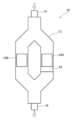
- FIG. 1 shows a plan view of the cooling structure 10 according to the first embodiment.
- the arrows in FIG. 1 indicate the flow direction of the refrigerant.
- a flow path through which the refrigerant flows is formed by the flow path forming member 12 made of resin.
- One inflow port 14 for flowing the refrigerant into the flow path is provided at one end of the flow path, and one outflow port 16 for flowing the refrigerant out of the flow path is provided at the other end of the flow path.
- two bodies to be cooled 18A and 18B to be cooled are arranged so as to be in contact with the outer wall surface of the flow path forming member 12.
- the flow path is branched between the inflow port 14 and the cooled body 18A and the cooled body 18B. Further, the branched flow paths merge between the cooled body 18A and the cooled body 18B and the outlet 16. Further, one of the branched flow paths is provided with a protruding portion 19 that projects outward from the flow path and comes into contact with the cooled body 18A on the downstream side in the flow direction of the refrigerant with respect to the cooled body 18A.
- two cooled bodies 18A and 18B are arranged, but other cooled bodies are arranged on the downstream side in the flow direction of the refrigerant from the cooled body 18A and the cooled body 18B. It may have been.
- the other cooled body is preferably a cooled body having a smaller amount of heat than the cooled body 18A and the cooled body 18B.
- the refrigerant supplied from the refrigerant supply means flows into the flow path from the inflow port 14.
- the refrigerant flowing into the flow path directly reaches the location where the cooled body 18A and the cooled body 18B are arranged in the cooling structure 10 through the branched flow path.
- the refrigerant that has reached the location where the cooled body 18A and the cooled body 18B are arranged cools the cooled body 18A and the cooled body 18B.
- the refrigerant that has reached the location where the cooled body 18A and the cooled body 18B are arranged does not cool the other cooled bodies before reaching the cooled body 18A and the cooled body 18B. Therefore, the refrigerant before cooling the cooled body can be supplied to the cooled body 18A and the cooled body 18B.
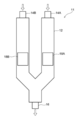
- FIG. 2 shows a plan view of the cooling structure 11 according to the second embodiment.
- the arrows in FIG. 2 indicate the flow direction of the refrigerant.
- a flow path through which the refrigerant flows is formed by the resin flow path forming member 12 as in the cooling structure 10.
- the cooling structure 11 is provided with two inflow ports 14A and 14B, and the flow path communicating with the inflow port 14A and the flow path communicating with the inflow port 14B merge on the downstream side in the flow direction of the refrigerant to flow.
- the outlet 16 is provided further downstream in the flow direction of the refrigerant than the confluence of the roads.
- two bodies to be cooled 18A and 18B to be cooled are arranged so as to be in contact with the outer wall surface of the flow path forming member 12.
- the refrigerant supplied from the refrigerant supply means flows into the flow path from the inflow port 14A and the inflow port 14B.
- the refrigerant flowing into the flow path from the inflow port 14A directly reaches the place where the cooled body 18A is arranged, and the refrigerant flowing into the flow path from the inflow port 14B directly reaches the place where the cooled body 18B is arranged.
- the refrigerant that has reached the location where the cooled body 18A and the cooled body 18B are arranged cools the cooled body 18A and the cooled body 18B.
- the refrigerant that has reached the location where the cooled body 18A and the cooled body 18B are arranged does not cool the other cooled bodies before reaching the cooled body 18A and the cooled body 18B. Therefore, the refrigerant before cooling the cooled body can be supplied to the cooled body 18A and the cooled body 18B.
- the flow path of the cooling structure includes a protrusion that protrudes outward from the inner wall on the upstream side in the direction in which the refrigerant flows, and a rectifying portion that rectifies the direction in which the refrigerant flows toward the protrusion. It may be. Since the flow path has a protruding portion and a rectifying portion, a flow of the refrigerant is formed in the protruding portion, the refrigerant supplied to the protruding portion is difficult to stay, and the occurrence of retention of the refrigerant accumulated in the protruding portion for a long period of time is suppressed. It is thought that it will be done. Further, it is considered that the cooling efficiency in the protruding portion is increased by suppressing the occurrence of retention in the protruding portion.
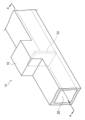
- FIG. 3 is a partial perspective view showing a portion of the cooling structure 10 where the protruding portion 19 is provided
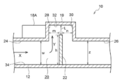
- FIG. 4 is a cross-sectional view taken along the vertical surface including the AA line of FIG.
- the cooled body 18A is omitted so that the structure of the protruding portion 19 can be easily understood.
- the flow path 20 through which the refrigerant flows is formed by the resin flow path forming member 12.
- the shape of the portion of the flow path where the protrusion 19 is provided may have a substantially rectangular cross section in a direction orthogonal to the direction in which the refrigerant flows, and the cross section may be circular or elliptical. It may be a shape, a polygon other than a rectangle, or the like.
- the flow path 20 includes a protruding portion 19 that projects vertically upward in the direction in which the refrigerant flows (arrow X direction in FIG. 4), and a rectifying unit 22 that rectifies the direction in which the refrigerant flows toward the protruding portion 19. Has.
- the protruding portion 19 is formed between the upper inner wall 24 on the upstream side and the upper inner wall 26 on the downstream side in the direction in which the refrigerant flows.
- the end portion of the rectifying portion 22 on the protruding portion 19 side protrudes vertically upward from the upper inner wall 24 on the upstream side and the upper inner wall 26 on the downstream side.
- the protruding portion 19 includes a side inner wall 28, a side inner wall 30, and an upper inner wall 32, all of which have a rectangular cross section in a direction parallel to the direction in which the refrigerant flows.
- the side inner wall 28 is a wall surface on the upstream side of the side inner wall 30, and the side inner wall 30 is a wall surface on the downstream side of the side inner wall 28.
- the cross section of the protruding portion in the direction parallel to the direction in which the refrigerant flows may be circular, elliptical, polygonal, or the like.
- the protruding portion may have a rectangular cross section orthogonal to the direction in which the refrigerant flows, as shown in FIG. 3, or may have a circular shape, an elliptical shape, a polygonal shape other than the rectangular shape, or the like.
- the projecting portion may project in the direction outside the flow path from the inner wall on the upstream side in the direction in which the refrigerant flows, and is not limited to a configuration in which the projecting portion projects vertically upward from the upper inner wall on the upstream side.
- it may protrude vertically downward from the lower inner wall on the upstream side, or may protrude toward the outside of the flow path of the side inner wall from the side inner wall on the upstream side.
- the "outside direction of the flow path” means a direction from the inner wall of the flow path to the outside of the flow path forming member via the outer wall.
- the rectifying unit 22 extends from the lower inner wall 34 toward the inside of the flow path 20.
- the rectifying unit 22 rectifies the direction in which the refrigerant flows in the protruding portion 19 side, for example, in the extending direction of the rectifying unit 22 (direction of arrow Y in FIG. 4).
- the rectifying portion 22 has a plate-like structure extending from at least a part of the lower inner wall 34 facing the upper inner wall 32 of the protruding portion 19 toward the protruding portion 19.
- the material constituting the rectifying section 22 may be a resin constituting the flow path forming member 12 described later, or a metal constituting the heat diffusion section described later.
- the end of the rectifying unit 22 on the protruding portion 19 side protrudes vertically upward from the upper inner wall 24 on the upstream side in the outward direction of the flow path.
- the flow of the refrigerant is preferably formed on the protrusion 19 side, and the refrigerant supplied to the protrusion 19 is less likely to stay.
- the rectifying portion is not particularly limited as long as it has a configuration that rectifies the direction in which the refrigerant flows toward the protruding portion. It may be configured to extend from at least a part of the portion toward the protruding portion side.
- the ratio (L / w) of the distance L between the upper inner wall 32 of the protruding portion 19 and the wall surface facing the upper inner wall 32 of the rectifying portion 22 and the width w of the flow path 20 on the upstream side of the protruding portion 19 is 1.
- the ratio (h / w) of the height h of the rectifying unit 22 in the vertically upward direction, which is the outer direction of the flow path, to the width w of the flow path 20 on the upstream side of the protruding portion 19 is 0.5 or more. Is preferable, and 1 or more is more preferable.
- the cooled body 18A is arranged so as to face the upper inner wall 24 on the upstream side and the side inner wall 28 of the protruding portion, and is cooled by the refrigerant flowing through the protruding portion 19.
- the body 18A has a structure in which it is cooled.
- Examples of the cooled body 18A arranged adjacent to the protrusion 19 include electronic components such as power semiconductors and capacitors.
- the body to be cooled 18A includes a heat sink (not shown) extending from the upper inner wall 24 on the upstream side toward the inside of the flow path 20, and a heat sink extending from the inner wall 28 toward the protrusion 19 (FIG. (Not shown) may be provided.
- the cooled body 18A When the cooled body 18A is provided with a heat sink, an insulating substrate, an insulating sheet, or the like that transfers the heat generated by the cooled body 18A to the heat sink may be provided between the cooled body 18A and the heat sink. Further, a part of the heat sink is embedded in the flow path forming member 12, and the heat generated by the cooled body 18A is transferred to the heat sink through the flow path forming member 12 without contacting the heat sink and the cooled body 18A. You may.
- the heat sink is provided with, for example, a plate-shaped heat diffusion portion facing the bottom portion of the body to be cooled 18A, and cooling fins extending into the flow path 20 from the surface of the heat diffusion portion on the upper inner wall 24 side.
- the heat sink includes a plate-shaped heat diffusion portion facing the side surface of the body to be cooled 18A, and cooling fins extending from the surface of the heat diffusion portion on the side inner wall 28 side to the protrusion 19. May be good.
- the cooling structure includes a plate-shaped and metal heat diffusing portion embedded in a flow path forming member that transfers heat from the object to be cooled or joined to the flow path forming member, and a heat diffusing portion. It may be further provided with cooling fins extending from the water flow path and having at least a surface made of resin. Further provided with a heat diffusion portion in which the cooling structure is plate-shaped and made of metal, and a cooling fin having a surface made of resin at least extending from the heat diffusion portion into the flow path, the heat conductivity is excellent.
- the heat received by the heat diffusion portion from the object to be cooled is diffused in the surface direction of the plate-shaped heat diffusion portion, and the heat diffused over a wide area is dissipated from the surface of the cooling fin having excellent heat dissipation. As a result, the cooling efficiency of the cooling structure is further improved.
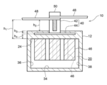
- FIG. 5A shows a cross section of the cooling structure 10 provided with the heat diffusion portion and the cooling fins when the cooled body 18A is a bus bar, when the cross section orthogonal to the direction in which the refrigerant flows in the flow path is observed.
- a cross-sectional view is shown.
- the cooling fins are provided in a region where the shape of the inner wall of the flow path becomes substantially rectangular when observing a cross section orthogonal to the direction in which the refrigerant flows in the flow path. Cooling fins extend from the inner wall on one side of the pair of inner walls facing each other in the substantially rectangular inner wall toward the inner wall on the other side.
- the cross-sectional shape of the flow path at the location where the cooling fins of the cooling structure are provided is not particularly limited, and may be substantially rectangular, and is a polygonal shape other than a circle, an ellipse, and a rectangle. It may have a shape other than a substantially rectangular shape such as. Further, in the present disclosure, the cross-sectional shape of the flow path other than the portion where the cooling fin of the cooling structure is provided is not particularly limited.
- the flow path 20 is a side connecting the upper inner wall 24 corresponding to one inner wall and the lower inner wall 34 corresponding to the other inner wall, and the upper inner wall 24 and the lower inner wall 34 of the pair of facing inner walls. It is surrounded by the inner wall 36 and the inner wall 38 of the side.
- a plurality of cylindrical cooling fins 46 are extended in the flow path 20 from the plate-shaped and metal heat diffusion portion 44.
- the cooling fin 46 is preferably made of resin like the flow path forming member 12.
- the metal heat diffusion portion 44 has high thermal conductivity, heat is easily diffused in the surface direction, and the heat diffused in the surface direction is easily dissipated by the resin cooling fins 46 having excellent heat dissipation. ..
- a part of the cooling fins 46 is shown by a dotted line.
- the extending directions of the plurality of cooling fins 46 are all substantially parallel.
- the bus bar 48 On the side of the heat diffusion portion 44 opposite to the side on which the cooling fins 46 are extended, the bus bar 48, which is a cooled body that is cooled by transferring heat to the heat diffusion portion 44, is formed by the bolt 50 and the nut 40. It is fixed.
- the nut 40 has a nut body 42 and a heat diffusion portion 44 provided on the side opposite to the side where the bolt 50 of the nut body 42 is inserted.
- the heat diffusion portion 44 is a quadrangular plate and is integrated with the nut body 42.
- the bus bar 48 is connected to an electronic component (not shown) such as a power semiconductor or a capacitor.
- the entire heat diffusion portion 44 of the nut 40 and the portion of the nut body 42 opposite to the side where the bolt 50 is inserted are embedded in the flow path forming member 12.
- the heat diffusion portion 44 is not limited to the configuration embedded in the flow path forming member 12, but is joined to the flow path forming member 12 as described later, for example, to the outer wall of the flow path forming member 12. It may have a different configuration.
- the heat diffusion portion 44 may be joined to the flow path forming member 12 by using the resin metal joining technique by laser roughening.
- the plurality of cooling fins 46 are all extended from the heat diffusion portion 44 into the flow path 20. As a result, the heat diffused in the surface direction by the heat diffusion unit 44 is easily dissipated by the cooling fins 46.
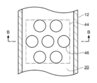
- FIG. 6 is a view of the region where the cooling fins 46 are provided in the cooling structure 10 of FIG. 5A as viewed from the insertion direction of the bolt 50.
- the description of the bus bar 48 and the like is omitted in FIG.
- the heat diffusion portion 44 is represented by a two-dot chain line so that the positional relationship between the cooling fin 46 and the heat diffusion portion 44 can be easily understood.
- FIG. 5A is a cross-sectional view taken along the line BB shown in FIG.
- the number of cooling fins 46 is seven, and the cooling fins 46 are provided within the range in which the heat diffusion portion 44 is arranged.
- the main surface of the heat diffusion portion 44 faces the flow path 20.
- bus bar 48 when a current flows through the bus bar 48, the bus bar 48 itself generates heat due to resistance loss. Further, the bus bar 48 is connected to an electronic component (not shown), and the heat generated from these electronic components is diffused through the bus bar 48 by energization. Therefore, the bus bar 48 tends to be in a high temperature state.
- the heat generated from the bus bar 48 itself and the heat diffused through the bus bar 48 are transferred to the portion integrated with the nut body 42 of the heat diffusion portion 44 via the bolt 50 and the nut body 42. Since the heat diffusion unit 44 is a quadrangular plate, the heat transferred to the heat diffusion unit 44 is diffused in the surface direction of the heat diffusion unit 44, and the heat can be diffused over a wide range.
- the heat diffusion portion 44 is arranged at the root portion of the cooling fin 46, and the heat diffused to the heat diffusion portion 44 reaches the root portion of the cooling fin 46 via the flow path forming member 12.
- the heat that has reached the root of the cooling fin 46 is transferred from the root of the cooling fin 46 toward the tip of the cooling fin 46 through the cooling fin 46.
- heat is transferred from the cooling fins 46 to the refrigerant by the refrigerant flowing through the flow path 20. In this way, the bus bar 48 and the objects to be cooled such as electronic components connected to the bus bar 48 are cooled.
- the area (area ratio) of the observed portion of the cooling fins 46 in the area of the flow path 20 is preferably 30% or more, more preferably 70% or more, and further preferably 100%.
- (Area ratio B) is preferably 30% or more, and more preferably 70% or more, from the viewpoint of improving the cooling efficiency.
- the area ratio B described above is preferably 70% or less, and more preferably 30% or less, from the viewpoint of resistance in the flow path 20.
- the heat diffusion portion 44 is a quadrangular plate-like object, but the heat diffusion portion 44 is not limited to a quadrangle, and may be a circle, an ellipse, a polygon other than the quadrangle, or the like.
- the surface of the cooling fin 46 may be at least made of resin, the entire cooling fin 46 may be made of resin, or the cooling fin 46 has a rod-shaped core material made of metal, and the surface of the core material is coated with resin. You may be. One end of the core material may be connected to the heat diffusion unit 44 from the viewpoint of improving the cooling efficiency.
- the tip of the cooling fin 46 has a flat shape orthogonal to the extending direction of the cooling fin 46, but the shape of the tip of the cooling fin 46 is not particularly limited and is hemispherical or conical. , Pyramid shape, etc.
- Examples of the object to be cooled include electronic components such as power semiconductors and capacitors in addition to the bus bar 48.
- the body to be cooled is an electronic component
- cooling fins may be provided at a position where the electronic component of the cooling structure is arranged.
- one or more cooling fins 46 extend from the heat diffusion portion 44 into the flow path 20, and preferably two or more.
- the cooling fins 46 may be arranged at a position away from the heat diffusion portion 44.
- the body to be cooled is a bus bar that transfers heat to the heat diffusion portion
- the distance h 1 is the bus bar 48 closest to the nut body 42. It means the distance between the inner wall surface of the flow path forming member 12 and the portion facing the bus bar 48 (upper inner wall 24 in FIG. 5A).
- the minimum distance h 2 between the bus bar 48 and the portion of the outer wall surface of the flow path forming member 12 facing the bus bar 48 is preferably 0.2 mm or more, preferably 0.5 mm, from the viewpoint of insulation. It is more preferably 1.0 mm or more, and further preferably 1.0 mm or more.
- the above-mentioned minimum distance h 2 is preferably 50 mm or less, more preferably 30 mm or less, still more preferably 10 mm or less, from the viewpoint of miniaturization of the cooling structure 10 and cooling efficiency of the bus bar 48. .. As shown in FIG.
- the minimum distance h 2 is the bus bar 48 closest to the nut body 42.
- the minimum distance h 3 from the surface of the heat diffusion portion 44 on the bus bar 48 side to the outer wall of the flow path forming member 12 is preferably 0.5 mm or more, preferably 1.5 mm or more, from the viewpoint of moldability. Is more preferable, and from the viewpoint of improving the cooling efficiency, it is preferably 2.5 mm or less.
- the minimum distance h 3 is 0 mm, at least a part of the surface of the heat diffusion portion 44 on the bus bar 48 side may not be covered with the flow path forming member 12.
- the minimum distance h 4 from the surface of the heat diffusion portion 44 on the flow path 20 side to the inner wall of the flow path forming member 12 is preferably 0.3 mm or more from the viewpoint of insulation, and is formable. From the viewpoint, it is more preferably 0.5 mm or more, and further preferably 1.5 mm or more. Further, the above-mentioned minimum distance h 4 is preferably 2.5 mm or less from the viewpoint of cooling efficiency.
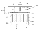
- Cooling structure 10 shown in FIG. 5B, the bus bar 48, the distance h 2 between the portion facing the bus bar 48 in the outer wall surface of the passage forming member 12, and the flow path formed from the surface of the bus bar 48 side of the thermal diffusion portion 44 It differs from the cooling structure 10 shown in FIG. 5A in that the distance h 3 to the outer wall of the member 12 is constant.
- the preferred range of the distance h 2 in FIG. 5B is the same as the minimum distance h 2 in FIG. 5A described above.
- Cooling structure 10 shown in FIG. 5C a point a distance h 3 between the surface of the bus bar 48 side of the thermal diffusion member 44 to the outer wall of the flow path forming member 12 is 0 mm, i.e., the thermal diffusion unit 44 busbar 48 side It differs from the cooling structure 10 shown in FIG. 5A or 5B in that the surface is not covered with the flow path forming member 12.
- the cooling structure 10 shown in FIG. 5C has excellent cooling efficiency.
- the contact area between the bus bar and the bolt and nut body is large.
- the shape of the portion of the bolt and nut that comes into contact with the bus bar is not particularly limited, and may be circular, elliptical, polygonal, or the like.
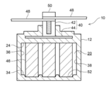
- FIG. 8 shows a cross-sectional view of another embodiment of the portion provided with the heat diffusion portion and the cooling fins of the cooling structure 10 shown in FIG. 5A
- FIG. 9 shows the heat of the cooling structure 10 shown in FIG. 5A.
- the end view of another embodiment about the part provided with the diffusing part and the cooling fin is shown.
- FIG. 8 shows a cross section of a region formed by a resin flow path forming member in which the shape of the inner wall of the flow path is substantially rectangular when observing a cross section orthogonal to the direction in which the refrigerant flows. It is shown.
- the cooling fins 46 extend from the upper inner wall 24 toward the lower inner wall 34, and the cooling fins 46 are in contact with the lower inner wall 34.
- the cooling fin 46 does not reach the lower inner wall 34, the refrigerant flowing between the tip of the cooling fin 46 and the lower inner wall 34 passes through without contacting the cooling fin 46.
- the refrigerant passing through without contacting the cooling fins 46 does not contribute to the cooling of the cooling fins 46.
- the cooling efficiency of the cooling structure 10 is high.
- the cooling fins 46 are in contact with the lower inner wall 34, the cooling is particularly performed when a load is applied from the upper inner wall 24 toward the lower inner wall 34 (or from the lower inner wall 34 toward the upper inner wall 24). It is possible to increase the strength of the structure 10.
- a concave recess 52 may be provided at a position where the cooling fins 46 come into contact with the lower inner wall 34.
- the tip of the cooling fin 46 is fitted in the recess 52.
- the tip of the cooling fin 46 is flattened perpendicular to the extending direction of the cooling fin 46, and the bottom surface of the recess 52 is parallel to the lower inner wall 34.
- the recess 52 may be concave having a radius of curvature larger than the radius of curvature of the tip of the cooling fin 46.
- the surface roughness Ra of the portion of the cooling fin 46 in contact with the refrigerant is preferably 10 ⁇ m or more.
- the surface roughness Ra of the portion of the cooling fin 46 in contact with the refrigerant is set to 10 ⁇ m or more, the heat emissivity of the cooling fin 46 increases, and heat is efficiently transferred from the cooling fin 46 to the refrigerant.
- the surface roughness Ra of the portion of the cooling fin 46 in contact with the refrigerant is 100 ⁇ m or more, the surface area of the cooling fin 46 becomes larger, and heat is more efficiently transferred from the cooling fin 46 to the refrigerant, which is preferable.
- the surface roughness Ra of the portion of the cooling fin 46 in contact with the refrigerant is preferably 500 ⁇ m or less from the viewpoint of moldability.
- the surface roughness Ra refers to a value measured based on JIS B0601: 2013.
- the length of the cooling fin 46 in the extending direction can be appropriately set based on the size of the flow path 20 and the like. From the viewpoint of moldability, the length of the cooling fin 46 in the extending direction is preferably 50 mm or less, and more preferably 30 mm or less. Further, the length of the cooling fin 46 in the extending direction is preferably 10 mm or more, and more preferably 30 mm or more, from the viewpoint of cooling efficiency.
- the width of the cooling fins 46 when observed from the direction in which the refrigerant flows can be appropriately set based on the size of the flow path 20 and the like. The width of the cooling fin 46 is preferably 1 mm or more, and more preferably 1.5 mm or more from the viewpoint of strength.
- the width of the cooling fins 46 is preferably 3 mm or less, and more preferably 2 mm or less, from the viewpoint of cooling efficiency.
- the length and width of the cooling fins 46 may be set in consideration of the required cooling performance, the strength of the cooling fins 46, and the ease of molding when the cooling fins 46 are molded by the injection molding method described later. ..
- the shape of the cooling fin 46 is not particularly limited.
- the cooling fin 46 may be circular as shown in FIG. 6 or the like when observing a cross section orthogonal to the extending direction, or may be a polygon such as an ellipse, a triangle, or a quadrangle.
- the cooling structure of the present disclosure may be provided with a temperature sensor for measuring the temperature of the refrigerant, or may be provided with a temperature sensor downstream of the region in which the cooling fins 46 are extended in the flow path 20. Further, the amount of the refrigerant may be adjusted according to the temperature of the temperature sensor, or a control unit may be provided for adjusting the amount of the refrigerant supplied from the refrigerant supply means according to the temperature of the temperature sensor.
- FIG. 10 is a cross-sectional view showing a main part of the cooling structure 54 according to the third embodiment.
- FIG. 10 shows a cross section of the flow path forming member 12 in the cooling structure 54 parallel to the flow direction of the refrigerant. In FIG. 10, the description of the cooling fin is omitted.
- the power semiconductor 56 which is a cooled body, is in contact with the flow path forming member 12 via a metal layer 58 provided on the outer wall of the flow path forming member 12.
- a bus bar 48 is connected to the power semiconductor 56 to ensure continuity with other power semiconductors and other electrical components (not shown).
- Cooling fins are extended from the upper inner wall 24 toward the lower inner wall 34 at a position where the flow path forming member 12 comes into contact with the power semiconductor 56. That is, the power semiconductor 56 is arranged at the root of the cooling fin (not shown). The heat generated from the power semiconductor 56 reaches the outer wall of the flow path forming member 12 via the metal layer 58, and the heat that reaches the root of the cooling fin (not shown) passes through the cooling fin from the root to the lower part of the cooling fin. Move towards the inner wall 34. At this time, heat is transferred from the cooling fins to the refrigerant by the refrigerant flowing through the flow path 20. Since the power semiconductor 56 comes into contact with the flow path forming member 12 via the metal layer 58, the heat generated from the power semiconductor 56 can be efficiently transferred to the cooling fins, and the cooling efficiency is improved.
- the metal layer 58 can shield a magnetic field in a low frequency region (particularly, a radio band) generated from the power semiconductor 56. Therefore, it is effective to provide the metal layer 58 on the outer wall of the flow path forming member 12 from the viewpoint of magnetic field shielding.
- the metal layer 58 may be provided on at least a part of the outer wall of the flow path forming member 12. Since the metal layer 58 is conductive, it is not necessary to provide the metal layer 58 at a place where insulation is required. Further, the metal layer 58 may be formed on the outer wall of the flow path forming member 12, and the portion where insulation is required may be covered with the resin layer.
- the metal layer 58 is preferably provided on the outer wall of the flow path forming member 12 on the side opposite to the side on which the cooled body is arranged. Further, as shown in FIG. 10, when the metal layer 58 is provided on a part of the outer wall of the flow path forming member 12 on the side where the cooled body is arranged, the arrangement of the cooled body in the flow path forming member 12 is provided. A region 60 in which the metal layer 58 is not provided may exist on the outer wall on the side opposite to the side where the metal layer 58 is provided. Further, a region on which the metal layer 58 is not provided may exist on the outer wall on the side opposite to the location where the heat diffusion portion 44 is arranged in FIG.
- the method for producing the cooling structure of the present disclosure is not particularly limited, and is not particularly limited, and is an injection molding method, a die slide injection molding method, a blow molding method, a compression molding method, a transfer molding method, an extrusion molding method, a casting molding method, etc.
- the usual molding method of a resin molded product can be adopted.
- the die slide injection molding method is preferable because high position accuracy may be required for manufacturing the cooling structure 10. Further, the portion of the nut 40 embedded in the flow path forming member 12 may be separately manufactured by an insert molding method.
- the surface of the mold used for molding the cooling fin 46 is provided with irregularities according to the surface roughness of the cooling fin 46.
- examples thereof include a method of adjusting the surface of the cooling fin 46 to a desired surface roughness by machining such as machining, blasting, and laser processing.
- the type of resin constituting the flow path forming member 12 and the cooling fin 46 is not particularly limited.
- the resin include polyethylene resin, polypropylene resin (PP), composite polypropylene resin (PPC), polyphenylene sulfide resin (PPS), polyphthalamide resin (PPA), and polybutylene terephthalate resin (PBT).
- Epoxy resin, phenol resin, polystyrene resin, polyethylene terephthalate resin, polyvinyl alcohol resin, vinyl chloride resin, ionomer resin, polyamide resin, acrylonitrile-butadiene-styrene copolymer resin (ABS) and polycarbonate resin Resin is mentioned.
- the resins constituting the flow path forming member 12 and the cooling fins 46 may be the same or different.
- the resin constituting the flow path forming member 12 and the cooling fin 46 may contain an inorganic filler.
- the inorganic filler include silica, alumina, zircon, magnesium oxide, calcium silicate, calcium carbonate, potassium titanate, silicon carbide, silicon nitride, boron nitride, beryllium and zirconia.
- examples of the inorganic filler having a flame-retardant effect include aluminum hydroxide and zinc borate.
- the inorganic filler contained in the resin constituting the flow path forming member 12 and the cooling fin 46 may be the same or different. Further, one of the resin constituting the flow path forming member 12 and the resin constituting the cooling fin 46 may contain an inorganic filler, and the other may not contain an inorganic filler.
- Examples of the metal constituting the heat diffusion unit 44 include metals such as aluminum, iron, copper, gold, silver, and stainless steel, and alloys.
- the heat diffusion portion 44 has a mesh shape from the viewpoint of suppressing the load on the cooling structure 10 due to the difference in the coefficient of thermal expansion between the resin constituting the flow path forming member 12 and the cooling fin 46 and the metal constituting the heat diffusion portion 44. , Punching metal or the like.
- the metals constituting the heat diffusion portion 44 are aluminum, iron, copper, gold, silver and stainless steel from the viewpoint of heat diffusion in the surface direction of the heat diffusion portion 44 and heat dissipation of the cooling fin 46.
- the resin constituting the cooling fin 46 is at least one selected from the group consisting of polyphenylene sulfide resin, polyamide resin, polyphthalamide resin, polybutylene terephthalate resin, phenol resin and epoxy. It is preferably at least one selected from the group consisting of based resins.
- Preferred polyamide-based resins include nylon 6, nylon 66 and the like.
- the type of refrigerant flowing through the flow path is not particularly limited.
- the refrigerant include water, liquids such as organic solvents, and gases such as air.
- Water used as a refrigerant may contain components such as antifreeze.
- the components constituting the metal layer 58 are not particularly limited, and zinc, aluminum, zinc-aluminum alloy, carbon steel, stainless steel, nickel, nickel alloy, tin, copper, copper alloy, silver, silver alloy, gold, Examples include gold alloys and molybdenum. Among these, silver and copper are preferable from the viewpoint of enhancing the magnetic field shielding effect. On the other hand, from the viewpoint of cooling efficiency, silver and gold are preferable.
- the method for forming the metal layer 58 is not particularly limited, and examples thereof include electrolytic plating, electroless plating, thin film deposition, sticking of a metal plate, and metal spraying.
- the metal layer 58 is preferably a metal sprayed layer formed by a metal spraying method from the viewpoint of formability, and zinc is preferable from the viewpoint of processability.
- the average thickness of the metal layer 58 is not particularly limited, and is preferably 1 ⁇ m to 2 mm.
- the average thickness of the metal layer 58 in contact with the power semiconductor 56 to be cooled is preferably 200 ⁇ m to 2 mm, more preferably 500 ⁇ m to 2 mm from the viewpoint of cooling efficiency.
- the average thickness of the metal layer 58 provided on the outer wall of the flow path forming member 12 opposite to the side on which the cooled body is arranged is preferably 1 ⁇ m to 2 mm, more preferably 200 ⁇ m to 2 mm from the viewpoint of magnetic field shielding. , 500 ⁇ m to 2 mm is more preferable.
- two or more outlets may be provided.
- the outflow amount of the refrigerant can be increased, and the cooling capacity of the cooling structure can be increased.
- the cooling structure of the present disclosure is effective for cooling a power module having a plurality of power semiconductors, an electronic component such as a capacitor, and a bus bar that electrically joins these electronic components in a vehicle equipped with a motor such as a hybrid vehicle and an electric vehicle. Is.
- a PPS resin plate having a length of 120 mm, a width of 120 mm, and a thickness of 5 mm was prepared and used as a test piece 1.
- a metal layer (zinc layer) having an average thickness of 200 ⁇ m was formed on one surface of the test piece 1 by a thermal spraying method. This was designated as test piece 2.
- an aluminum plate having a length of 120 mm, a width of 120 mm, and a thickness of 500 ⁇ m was used as the test piece 3.
- the magnetic field shielding performance of the test piece 1, the test piece 2, and the test piece 3 was evaluated by the magnetic field shielding effect evaluation device in the KEC method (500 Hz to 1 GHz) shown below. The obtained results are shown in FIG. As is clear from FIG. 11, according to the test piece 2 and the test piece 3, it can be seen that an excellent magnetic field shielding effect can be obtained as compared with the test piece 1.
- a water channel model 1 having an outer diameter of 30 mm in width ⁇ 15 mm in length, an inner diameter of 25 mm in width ⁇ 10 mm in length, and a length of 110 mm was formed.
- a metal layer 58 (zinc layer) having an average thickness of 200 ⁇ m was formed on the upper surface of the outer wall of 110 mm ⁇ 30 mm in the water channel model 1 by a thermal spraying method. This was designated as a waterway model 2.
- An iron block 62 having a size of 95 mm ⁇ 25 mm ⁇ 15 mm heated to 100 ° C. is shown in FIG.
- Cooling structure 12 Flow path forming member 14 (14A, 14B) Inflow port 16 Outlet 18A, 18B Cooled body 19 Protruding part 20 Flow path 22 Rectifying part 40 Nut 42 Nut body 44 Heat diffusion part 46 Cooling Fin 48 Busbar 50 Bolt 52 Depression 56 Power semiconductor 58 Metal layer 60 Area where metal layer 58 is not provided 62 Iron block
Landscapes
- Physics & Mathematics (AREA)
- Thermal Sciences (AREA)
- Engineering & Computer Science (AREA)
- Microelectronics & Electronic Packaging (AREA)
- Cooling Or The Like Of Electrical Apparatus (AREA)
- Cooling Or The Like Of Semiconductors Or Solid State Devices (AREA)
Abstract
Description
モータを駆動する際には、パワー半導体、キャパシタ等、これら電子部品を接合するバスバーに大電流の流れることがある。この場合、スイッチング損失、抵抗損失等によって駆動手段が発熱するため、駆動手段を効率的に冷却する必要がある。
また、金属製のヒートシンクを駆動手段等の冷却対象に組み込むためには、多くの工数を要することがある。そのため、金属製のヒートシンクを用いることなく冷却効率に優れる冷却方法が求められている。
<1> 冷媒を流通させる流路を形成する樹脂製の流路形成部材と、
前記冷媒を前記流路に流入させる流入口と、
前記冷媒を前記流路から流出させる流出口と、
前記冷媒により冷却される複数の被冷却体と、を備え、
前記流入口から流入した前記冷媒が前記複数の被冷却体のうちの少なくとも2つの被冷却体に直接到達するように、前記流路が構成される冷却構造体。
<2> 前記流路が、前記流入口と前記被冷却体との間で分岐しており、分岐した前記流路を流通して前記冷媒が前記複数の被冷却体のうちの少なくとも2つの被冷却体に直接到達する<1>に記載の冷却構造体。
<3> 前記流入口を少なくとも2つ備え、前記少なくとも2つの流入口の各々から流入した前記冷媒が前記複数の被冷却体のうちの少なくとも2つの被冷却体に直接到達する<1>に記載の冷却構造体。
<4> 前記流路が、前記冷媒が流通する方向における上流側の内壁よりも流路外方向に突出する突出部と、前記冷媒が流通する方向を前記突出部側に整流する整流部と、を有する<1>~<3>のいずれか1項に記載の冷却構造体。
<5> 前記被冷却体からの熱を伝熱する前記流路形成部材に埋設された、又は、前記流路形成部材に接合された、板状かつ金属製である熱拡散部と、
前記熱拡散部から前記流路内に延設され、少なくとも表面が樹脂製の冷却フィンと、をさらに備える<1>~<4>のいずれか1項に記載の冷却構造体。
<6> 前記被冷却体の少なくとも1つが前記熱拡散部に伝熱するバスバーであり、
前記流路形成部材の外壁面と、前記バスバーとの間に空間があり、前記流路形成部材と前記バスバーとが接触していない<5>に記載の冷却構造体。
<7> 前記冷却フィンの先端が、前記流路の内壁に接触する<5>又は<6>に記載の冷却構造体。
<8> 前記冷却フィンの前記冷媒と接触する部分の表面粗さRaが、10μm以上である<5>~<7>のいずれか1項に記載の冷却構造体。
<9> 前記流路形成部材の外壁の少なくとも一部に、金属層が設けられた<1>~<8>のいずれか1項に記載の冷却構造体。
<10> 前記金属層が、金属溶射層である<9>に記載の冷却構造体。
本開示の冷却構造体は、冷媒を流通させる流路を形成する樹脂製の流路形成部材と、前記冷媒を前記流路に流入させる流入口と、前記冷媒を前記流路から流出させる流出口と、前記冷媒により冷却される複数の被冷却体と、を備え、前記流入口から流入した前記冷媒が前記複数の被冷却体のうちの少なくとも2つの被冷却体に直接到達するように、前記流路が構成されるものである。
本開示の冷却構造体では、流入口から流入した冷媒が被冷却体のうちの少なくとも2つの被冷却体に直接到達するように流路が構成されることから、熱量の大きい少なくとも2つの被冷却体が存在する場合に、これら複数の被冷却体に対して冷媒を直接供給することが可能となる。そのため、他の被冷却体への冷却に寄与しておらず冷却能力に優れる冷媒を熱量の大きい被冷却体に供給することができ、冷却効率が向上する。
なお、本開示の冷却構造体では、流路における冷媒が流通する方向と直交する断面を観察したときに、流路の少なくとも一部に内壁の形状が略矩形となる領域が存在してもよく、円形、楕円形、矩形以外の多角形等の、略矩形以外の内壁の形状を呈する領域が存在していてもよい。
また、分岐した流路の一方には、被冷却体18Aよりも冷媒の流れ方向下流側に、流路外方向に突出して被冷却体18Aと接触する突出部19が設けられている。
なお、冷却構造体10では2つの被冷却体18A及び被冷却体18Bが配置されているが、被冷却体18A及び被冷却体18Bよりも冷媒の流れ方向下流側に他の被冷却体が配置されていてもよい。他の被冷却体は、被冷却体18A及び被冷却体18Bよりも熱量の小さい被冷却体であることが好ましい。
流路が突出部と整流部とを有することで、突出部に冷媒の流れが形成され、突出部に供給された冷媒が留まりにくくなり、長期間にわたって冷媒が突出部に溜まる滞留の発生が抑制されると考えられる。また、突出部における滞留の発生が抑制されることにより、突出部における冷却効率が高まると考えられる。
図3及び図4において、冷媒を流通させる流路20が樹脂製の流路形成部材12により形成されている。流路における突出部19の設けられた箇所の形状は、図3及び図4に示すように、冷媒が流通する方向と直交する方向における断面が略矩形であってもよく、断面が円形、楕円形、矩形以外の多角形等であってもよい。
本開示において、「流路外方向」とは、流路の内壁から外壁を介して流路形成部材の外部に向かう方向を意味する。
被冷却体18Aは、上流側の上部内壁24から流路20内に向けて延設されたヒートシンク(図示せず)、及び側部内壁28から突出部19に向けて延設されたヒートシンク(図示せず)を備えていてもよい。
図5Aに示す冷却構造体10では、冷却フィンが、流路の冷媒が流通する方向と直交する断面を観察したときに流路の内壁の形状が略矩形となる領域に設けられている。略矩形とされた内壁における対向する一対の内壁のうちの一方側の内壁から他方側の内壁に向けて冷却フィンが延設されている。
なお、本開示において、冷却構造体の冷却フィンの設けられた箇所の流路の断面形状は特に限定されるものではなく、略矩形であってもよく、円形、楕円形、矩形以外の多角形等の、略矩形以外の形状であってもよい。
また、本開示において、冷却構造体の冷却フィンの設けられた箇所以外の流路の断面形状は特に限定されるものではない。
図5Aでは、冷却フィン46の一部が点線で示されている。
複数の冷却フィン46の延設方向はいずれも略平行とされる。複数の冷却フィン46の延設方向を略平行とすることで、金型を用いて冷却フィン46を備える流路形成部材12を製造する際に、金型から冷却フィン46を引き抜きやすくなる。そのため、金型を用いた冷却フィン46を備える流路形成部材12の製造が容易になる。
バスバー48は、パワー半導体、キャパシタ等の不図示の電子部品と接続されている。
図6では、冷却フィン46は7本とされており、熱拡散部44の配置された範囲内に冷却フィン46が設けられている。また、熱拡散部44の主面(熱拡散部44のナット本体42と一体化されている側とは反対側の面)は流路20と対向している。
例えば、図7に示すように、熱拡散部44から外れた位置に冷却フィン46が配置されていてもよい。
なお、図5Aに示すように複数のバスバー48(図中では2つ)が、ボルト50とナット本体42とで固定されている場合、距離h1は、ナット本体42に最も近いバスバー48と、流路形成部材12の内壁面におけるバスバー48と対面する部分(図5Aにおける上部内壁24)と、の距離を意味する。
なお、図5Aに示すように複数のバスバー48(図中では2つ)が、ボルト50とナット本体42とで固定されている場合、最小距離h2は、ナット本体42に最も近いバスバー48と、流路形成部材12の外壁面におけるバスバー48と対面する部分と、の最小距離を意味する。
図5B中の距離h3の好ましい範囲は、絶縁性の観点から、0mm超であることが好ましく、成形性の観点から、0.5mm以上であることがより好ましく、1.5mm以上であることがさらに好ましく、冷却効率の観点から、2.5mm以下であることが好ましい。
図5Cに示す冷却構造体10は、冷却効率に優れる。
図8は、図5Aに示す冷却構造体10の熱拡散部と冷却フィンとを備える箇所についての、他の実施形態の断面図を示し、図9は、図5Aに示す冷却構造体10の熱拡散部と冷却フィンとを備える箇所についての、他の実施形態の端面図を示す。
図8には、樹脂製の流路形成部材により形成された流路について、冷媒が流通する方向と直交する断面を観察したときに当該流路の内壁の形状が略矩形となる領域の断面が示されている。
本開示において、表面粗さRaは、JIS B0601:2013に基づいて測定された値をいう。
冷媒が流通する方向から観察したときの冷却フィン46の幅は、流路20の大きさ等に基づいて適宜設定することができる。冷却フィン46の幅は、強度の観点から1mm以上であることが好ましく、1.5mm以上であることがより好ましい。また、冷却フィン46の幅は、冷却効率の観点から、3mm以下であることが好ましく、2mm以下であることがより好ましい。
要求される冷却性能及び冷却フィン46の強度並びに冷却フィン46を後述のインジェクション成形法により成形する際の成形のしやすさを加味して、冷却フィン46の長さ及び幅を設定してもよい。
図10に示す冷却構造体54では、被冷却体であるパワー半導体56が、流路形成部材12の外壁に設けられた金属層58を介して流路形成部材12と接している。パワー半導体56にはバスバー48が接続されており、不図示の他のパワー半導体その他の電気部品と導通が確保されている。流路形成部材12のパワー半導体56と接触する箇所には、不図示の冷却フィンが上部内壁24から下部内壁34に向けて延設されている。つまり、不図示の冷却フィンの根元部に、パワー半導体56が配置されている。
パワー半導体56から生じた熱は、金属層58を介して流路形成部材12の外壁に達し、さらに不図示の冷却フィンの根元部に到達した熱は、冷却フィンを通じて冷却フィンの根元部から下部内壁34に向けて移動する。このときに、流路20を流通する冷媒により冷却フィンから熱が冷媒に移動する。パワー半導体56が金属層58を介して流路形成部材12と接するため、パワー半導体56から生じた熱が、効率的に冷却フィンへ移動しやすくなり、冷却効率が向上する。
金属層58は、例えば、流路形成部材12における被冷却体の配置された側とは反対側の外壁に設けることが好ましい。また、図10に示すように、金属層58が流路形成部材12における被冷却体の配置された側の外壁の一部に設けられている場合、流路形成部材12における被冷却体の配置された側とは反対側の外壁には、金属層58の設けられていない領域60が存在してもよい。さらに、図10における熱拡散部44の配置された箇所とは反対側の外壁には、金属層58の設けられていない領域が存在してもよい。
また、ナット40の流路形成部材12に埋設されている箇所は、別途インサート成形法により製造さてもよい。
流路形成部材12及び冷却フィン46を構成する樹脂に含まれる無機充填材は、同じであっても異なっていてもよい。また、流路形成部材12を構成する樹脂及び冷却フィン46を構成する樹脂の一方に無機充填材が含まれ、他方に無機充填材が含まれなくともよい。
金属層58を形成する方法は特に限定されるものではなく、電解メッキ、無電解メッキ、蒸着、金属板の張り付け、金属溶射等が挙げられる。金属層58は、形成性の観点から、金属溶射法により形成された金属溶射層であることが好ましく、加工性の観点から亜鉛が好ましい。
縦120mm、横120mm、厚み5mmのPPS樹脂板を準備し、試験片1とした。
試験片1の一方の面に、溶射法により平均厚み200μmの金属層(亜鉛層)を形成した。これを試験片2とした。
また、縦120mm、横120mm、厚み500μmのアルミニウム板を試験片3とした。
試験片1、試験片2及び試験片3について、磁界シールド性能を以下に示すKEC法(500Hzから1GHz)における磁界シールド効果評価用装置で評価した。
得られた結果を図11に示す。図11から明らかなように、試験片2及び試験片3によれば、試験片1に比較して優れた磁界シールド効果の得られることがわかる。
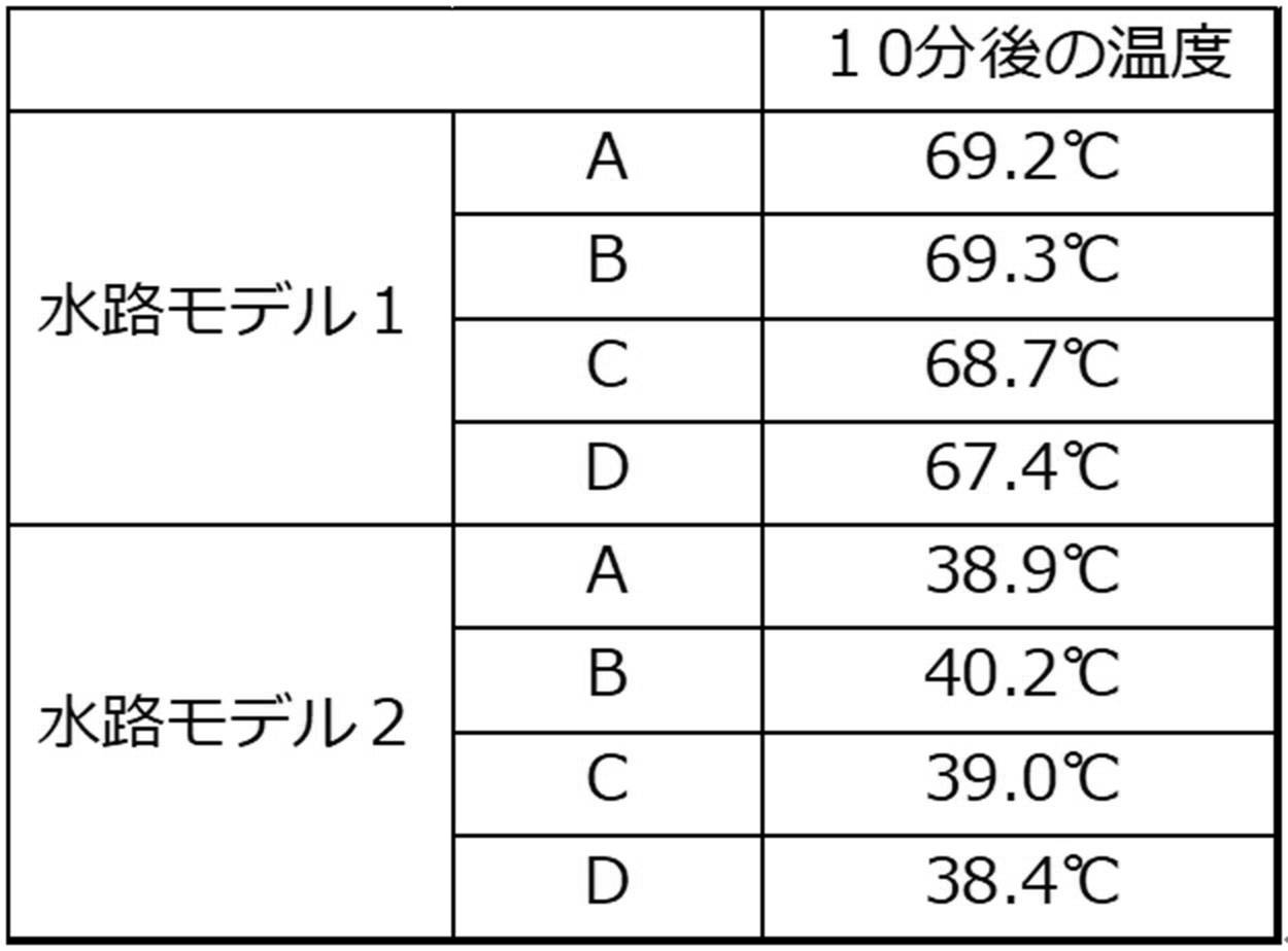
PPS樹脂を用いて、外径が横30mm×縦15mmで、内径が横25mm×縦10mmで、長さが110mmの断面矩形の水路モデル1を形成した。水路モデル1における110mm×30mmの外壁の上面に、溶射法により平均厚み200μmの金属層58(亜鉛層)を形成した。これを水路モデル2とした。
水路モデル1の110mm×30mmの外壁及び水路モデル2の金属層58を形成した面上に、各々、100℃に熱した95mm×25mm×15mmの大きさの鉄ブロック62を図12に示すようにして配置し、各水路モデル内に20℃の水を8L/分の流量で流通させた。
鉄ブロック62の配置直後から、図12に示すA~Dの計4箇所の温度変化を、KEYENCE製 高機能レコーダ GR-3500を用いて測定したところ、鉄ブロック62の配置から10分後の各測定箇所の温度は、下記表1に示すとおりであり、金属層58は被冷却体の冷却に有効であることが明らかとなった。
本明細書に記載された全ての文献、特許出願、及び技術規格は、個々の文献、特許出願、及び技術規格が参照により取り込まれることが具体的かつ個々に記された場合と同程度に、本明細書中に参照により取り込まれる。
12 流路形成部材
14(14A、14B) 流入口
16 流出口
18A、18B 被冷却体
19 突出部
20 流路
22 整流部
40 ナット
42 ナット本体
44 熱拡散部
46 冷却フィン
48 バスバー
50 ボルト
52 窪み
56 パワー半導体
58 金属層
60 金属層58の設けられていない領域
62 鉄ブロック
Claims (10)
- 冷媒を流通させる流路を形成する樹脂製の流路形成部材と、
前記冷媒を前記流路に流入させる流入口と、
前記冷媒を前記流路から流出させる流出口と、
前記冷媒により冷却される複数の被冷却体と、を備え、
前記流入口から流入した前記冷媒が前記複数の被冷却体のうちの少なくとも2つの被冷却体に直接到達するように、前記流路が構成される冷却構造体。 - 前記流路が、前記流入口と前記被冷却体との間で分岐しており、分岐した前記流路を流通して前記冷媒が前記複数の被冷却体のうちの少なくとも2つの被冷却体に直接到達する請求項1に記載の冷却構造体。
- 前記流入口を少なくとも2つ備え、前記少なくとも2つの流入口の各々から流入した前記冷媒が前記複数の被冷却体のうちの少なくとも2つの被冷却体に直接到達する請求項1に記載の冷却構造体。
- 前記流路が、前記冷媒が流通する方向における上流側の内壁よりも流路外方向に突出する突出部と、前記冷媒が流通する方向を前記突出部側に整流する整流部と、を有する請求項1~請求項3のいずれか1項に記載の冷却構造体。
- 前記被冷却体からの熱を伝熱する前記流路形成部材に埋設された、又は、前記流路形成部材に接合された、板状かつ金属製である熱拡散部と、
前記熱拡散部から前記流路内に延設され、少なくとも表面が樹脂製の冷却フィンと、をさらに備える請求項1~請求項4のいずれか1項に記載の冷却構造体。 - 前記被冷却体の少なくとも1つが前記熱拡散部に伝熱するバスバーであり、
前記流路形成部材の外壁面と、前記バスバーとの間に空間があり、前記流路形成部材と前記バスバーとが接触していない請求項5に記載の冷却構造体。 - 前記冷却フィンの先端が、前記流路の内壁に接触する請求項5又は請求項6に記載の冷却構造体。
- 前記冷却フィンの前記冷媒と接触する部分の表面粗さRaが、10μm以上である請求項5~請求項7のいずれか1項に記載の冷却構造体。
- 前記流路形成部材の外壁の少なくとも一部に、金属層が設けられた請求項1~請求項8のいずれか1項に記載の冷却構造体。
- 前記金属層が、金属溶射層である請求項9に記載の冷却構造体。
Priority Applications (1)
| Application Number | Priority Date | Filing Date | Title |
|---|---|---|---|
| JP2021509344A JP7164020B2 (ja) | 2019-03-22 | 2020-03-19 | 冷却構造体 |
Applications Claiming Priority (2)
| Application Number | Priority Date | Filing Date | Title |
|---|---|---|---|
| JP2019-055693 | 2019-03-22 | ||
| JP2019055693 | 2019-03-22 |
Publications (1)
| Publication Number | Publication Date |
|---|---|
| WO2020196332A1 true WO2020196332A1 (ja) | 2020-10-01 |
Family
ID=72609371
Family Applications (1)
| Application Number | Title | Priority Date | Filing Date |
|---|---|---|---|
| PCT/JP2020/012484 Ceased WO2020196332A1 (ja) | 2019-03-22 | 2020-03-19 | 冷却構造体 |
Country Status (2)
| Country | Link |
|---|---|
| JP (1) | JP7164020B2 (ja) |
| WO (1) | WO2020196332A1 (ja) |
Citations (7)
| Publication number | Priority date | Publication date | Assignee | Title |
|---|---|---|---|---|
| JPH08204068A (ja) * | 1995-01-20 | 1996-08-09 | Fuji Electric Co Ltd | モジュール構造の半導体装置 |
| JP2003003248A (ja) * | 2001-06-25 | 2003-01-08 | Sawaki Kogyo:Kk | 金属溶射層被覆シート |
| JP2005079337A (ja) * | 2003-08-29 | 2005-03-24 | Toshiba Corp | 液冷装置及び液冷システム |
| WO2011145618A1 (ja) * | 2010-05-19 | 2011-11-24 | 日本電気株式会社 | 沸騰冷却器 |
| JP2012015240A (ja) * | 2010-06-30 | 2012-01-19 | Denso Corp | 半導体装置及びその製造方法 |
| WO2016080333A1 (ja) * | 2014-11-21 | 2016-05-26 | 株式会社村田製作所 | モジュール |
| JP2017161204A (ja) * | 2016-03-11 | 2017-09-14 | 富士通株式会社 | 冷却装置、冷却装置の製造方法、及び電子機器 |
-
2020
- 2020-03-19 WO PCT/JP2020/012484 patent/WO2020196332A1/ja not_active Ceased
- 2020-03-19 JP JP2021509344A patent/JP7164020B2/ja active Active
Patent Citations (7)
| Publication number | Priority date | Publication date | Assignee | Title |
|---|---|---|---|---|
| JPH08204068A (ja) * | 1995-01-20 | 1996-08-09 | Fuji Electric Co Ltd | モジュール構造の半導体装置 |
| JP2003003248A (ja) * | 2001-06-25 | 2003-01-08 | Sawaki Kogyo:Kk | 金属溶射層被覆シート |
| JP2005079337A (ja) * | 2003-08-29 | 2005-03-24 | Toshiba Corp | 液冷装置及び液冷システム |
| WO2011145618A1 (ja) * | 2010-05-19 | 2011-11-24 | 日本電気株式会社 | 沸騰冷却器 |
| JP2012015240A (ja) * | 2010-06-30 | 2012-01-19 | Denso Corp | 半導体装置及びその製造方法 |
| WO2016080333A1 (ja) * | 2014-11-21 | 2016-05-26 | 株式会社村田製作所 | モジュール |
| JP2017161204A (ja) * | 2016-03-11 | 2017-09-14 | 富士通株式会社 | 冷却装置、冷却装置の製造方法、及び電子機器 |
Also Published As
| Publication number | Publication date |
|---|---|
| JPWO2020196332A1 (ja) | 2021-10-21 |
| JP7164020B2 (ja) | 2022-11-01 |
Similar Documents
| Publication | Publication Date | Title |
|---|---|---|
| CN101312183B (zh) | 半导体装置 | |
| US20110299244A1 (en) | Cooling member for heat containing device | |
| US9226430B2 (en) | Power semiconductor module | |
| US20130148301A1 (en) | Magnetic fluid cooling devices and power electronics assemblies | |
| JP4015060B2 (ja) | 直接水冷型パワー半導体モジュール構造 | |
| US20160190032A1 (en) | Wiring board and semiconductor package including wiring board | |
| US20220293490A1 (en) | Cooling system | |
| JP7164021B2 (ja) | 冷却構造体 | |
| JP7164018B2 (ja) | 冷却構造体 | |
| JP7164019B2 (ja) | 冷却構造体 | |
| JP7164022B2 (ja) | 冷却構造体 | |
| JP7164023B2 (ja) | 冷却構造体 | |
| WO2020196332A1 (ja) | 冷却構造体 | |
| JP6880776B2 (ja) | 電力変換装置 | |
| US12540779B2 (en) | Cooling structure | |
| CN115088398A (zh) | 散热装置、包括这种装置的电气系统及相关制造方法 | |
| CN214070505U (zh) | 一种用于车载娱乐系统的散热片 | |
| CN120499994A (zh) | 换热装置、车载电子设备及车辆 | |
| JP2003007943A (ja) | 熱交換装置 |
Legal Events
| Date | Code | Title | Description |
|---|---|---|---|
| 121 | Ep: the epo has been informed by wipo that ep was designated in this application |
Ref document number: 20776439 Country of ref document: EP Kind code of ref document: A1 |
|
| ENP | Entry into the national phase |
Ref document number: 2021509344 Country of ref document: JP Kind code of ref document: A |
|
| NENP | Non-entry into the national phase |
Ref country code: DE |
|
| 32PN | Ep: public notification in the ep bulletin as address of the adressee cannot be established |
Free format text: NOTING OF LOSS OF RIGHTS PURSUANT TO RULE 112(1) EPC (EPO FORM 1205A DATED 22/12/2021) |
|
| 122 | Ep: pct application non-entry in european phase |
Ref document number: 20776439 Country of ref document: EP Kind code of ref document: A1 |