WO2020195945A1 - 航空機用シート構造体 - Google Patents
航空機用シート構造体 Download PDFInfo
- Publication number
- WO2020195945A1 WO2020195945A1 PCT/JP2020/011075 JP2020011075W WO2020195945A1 WO 2020195945 A1 WO2020195945 A1 WO 2020195945A1 JP 2020011075 W JP2020011075 W JP 2020011075W WO 2020195945 A1 WO2020195945 A1 WO 2020195945A1
- Authority
- WO
- WIPO (PCT)
- Prior art keywords
- seat
- monitor
- area
- aircraft
- region
- Prior art date
Links
- 238000005192 partition Methods 0.000 claims abstract description 20
- 230000007246 mechanism Effects 0.000 claims description 13
- 210000000078 claw Anatomy 0.000 description 8
- 238000013459 approach Methods 0.000 description 5
- 238000004804 winding Methods 0.000 description 5
- 125000002066 L-histidyl group Chemical group [H]N1C([H])=NC(C([H])([H])[C@](C(=O)[*])([H])N([H])[H])=C1[H] 0.000 description 2
- 239000002131 composite material Substances 0.000 description 2
- 239000011358 absorbing material Substances 0.000 description 1
- 230000008859 change Effects 0.000 description 1
- 238000007796 conventional method Methods 0.000 description 1
- 238000013461 design Methods 0.000 description 1
- 230000006872 improvement Effects 0.000 description 1
- 238000000034 method Methods 0.000 description 1
- 238000012986 modification Methods 0.000 description 1
- 230000004048 modification Effects 0.000 description 1
- 230000004044 response Effects 0.000 description 1
Images

Classifications
-
- B—PERFORMING OPERATIONS; TRANSPORTING
- B64—AIRCRAFT; AVIATION; COSMONAUTICS
- B64D—EQUIPMENT FOR FITTING IN OR TO AIRCRAFT; FLIGHT SUITS; PARACHUTES; ARRANGEMENT OR MOUNTING OF POWER PLANTS OR PROPULSION TRANSMISSIONS IN AIRCRAFT
- B64D11/00—Passenger or crew accommodation; Flight-deck installations not otherwise provided for
- B64D11/06—Arrangements of seats, or adaptations or details specially adapted for aircraft seats
- B64D11/0601—Arrangement of seats for non-standard seating layouts, e.g. seats staggered horizontally or vertically, arranged in an angled or fishbone layout, or facing in other directions than the direction of flight
-
- B—PERFORMING OPERATIONS; TRANSPORTING
- B64—AIRCRAFT; AVIATION; COSMONAUTICS
- B64D—EQUIPMENT FOR FITTING IN OR TO AIRCRAFT; FLIGHT SUITS; PARACHUTES; ARRANGEMENT OR MOUNTING OF POWER PLANTS OR PROPULSION TRANSMISSIONS IN AIRCRAFT
- B64D11/00—Passenger or crew accommodation; Flight-deck installations not otherwise provided for
- B64D11/0015—Arrangements for entertainment or communications, e.g. radio, television
- B64D11/00151—Permanently mounted seat back monitors
-
- B—PERFORMING OPERATIONS; TRANSPORTING
- B64—AIRCRAFT; AVIATION; COSMONAUTICS
- B64D—EQUIPMENT FOR FITTING IN OR TO AIRCRAFT; FLIGHT SUITS; PARACHUTES; ARRANGEMENT OR MOUNTING OF POWER PLANTS OR PROPULSION TRANSMISSIONS IN AIRCRAFT
- B64D11/00—Passenger or crew accommodation; Flight-deck installations not otherwise provided for
- B64D11/06—Arrangements of seats, or adaptations or details specially adapted for aircraft seats
- B64D11/0602—Seat modules, i.e. seat systems including furniture separate from the seat itself
- B64D11/0605—Seat modules, i.e. seat systems including furniture separate from the seat itself including tables or desks
-
- B—PERFORMING OPERATIONS; TRANSPORTING
- B64—AIRCRAFT; AVIATION; COSMONAUTICS
- B64D—EQUIPMENT FOR FITTING IN OR TO AIRCRAFT; FLIGHT SUITS; PARACHUTES; ARRANGEMENT OR MOUNTING OF POWER PLANTS OR PROPULSION TRANSMISSIONS IN AIRCRAFT
- B64D11/00—Passenger or crew accommodation; Flight-deck installations not otherwise provided for
- B64D11/06—Arrangements of seats, or adaptations or details specially adapted for aircraft seats
- B64D11/0606—Arrangements of seats, or adaptations or details specially adapted for aircraft seats with privacy shells, screens, separators or the like
-
- B—PERFORMING OPERATIONS; TRANSPORTING
- B64—AIRCRAFT; AVIATION; COSMONAUTICS
- B64D—EQUIPMENT FOR FITTING IN OR TO AIRCRAFT; FLIGHT SUITS; PARACHUTES; ARRANGEMENT OR MOUNTING OF POWER PLANTS OR PROPULSION TRANSMISSIONS IN AIRCRAFT
- B64D11/00—Passenger or crew accommodation; Flight-deck installations not otherwise provided for
- B64D11/06—Arrangements of seats, or adaptations or details specially adapted for aircraft seats
- B64D11/0627—Seats combined with storage means
- B64D11/0636—Personal storage means or waste disposal bags
-
- B—PERFORMING OPERATIONS; TRANSPORTING
- B64—AIRCRAFT; AVIATION; COSMONAUTICS
- B64D—EQUIPMENT FOR FITTING IN OR TO AIRCRAFT; FLIGHT SUITS; PARACHUTES; ARRANGEMENT OR MOUNTING OF POWER PLANTS OR PROPULSION TRANSMISSIONS IN AIRCRAFT
- B64D11/00—Passenger or crew accommodation; Flight-deck installations not otherwise provided for
- B64D11/06—Arrangements of seats, or adaptations or details specially adapted for aircraft seats
- B64D11/0639—Arrangements of seats, or adaptations or details specially adapted for aircraft seats with features for adjustment or converting of seats
- B64D11/064—Adjustable inclination or position of seats
-
- B—PERFORMING OPERATIONS; TRANSPORTING
- B64—AIRCRAFT; AVIATION; COSMONAUTICS
- B64D—EQUIPMENT FOR FITTING IN OR TO AIRCRAFT; FLIGHT SUITS; PARACHUTES; ARRANGEMENT OR MOUNTING OF POWER PLANTS OR PROPULSION TRANSMISSIONS IN AIRCRAFT
- B64D11/00—Passenger or crew accommodation; Flight-deck installations not otherwise provided for
- B64D11/06—Arrangements of seats, or adaptations or details specially adapted for aircraft seats
- B64D11/0639—Arrangements of seats, or adaptations or details specially adapted for aircraft seats with features for adjustment or converting of seats
- B64D11/0641—Seats convertible into beds
-
- B—PERFORMING OPERATIONS; TRANSPORTING
- B64—AIRCRAFT; AVIATION; COSMONAUTICS
- B64D—EQUIPMENT FOR FITTING IN OR TO AIRCRAFT; FLIGHT SUITS; PARACHUTES; ARRANGEMENT OR MOUNTING OF POWER PLANTS OR PROPULSION TRANSMISSIONS IN AIRCRAFT
- B64D11/00—Passenger or crew accommodation; Flight-deck installations not otherwise provided for
- B64D11/06—Arrangements of seats, or adaptations or details specially adapted for aircraft seats
- B64D11/0639—Arrangements of seats, or adaptations or details specially adapted for aircraft seats with features for adjustment or converting of seats
- B64D11/0643—Adjustable foot or leg rests
Definitions
- the present invention relates to an aircraft seat structure.
- a seat structure that can selectively change between an upright state in which the backrest is upright and a reclining state in which the backrest or the like tilts and approaches a horizontal state is mounted as a seat for first class or business class.
- seat structures are configured as seat modules (seat units) in which reclining seats are arranged in a space partitioned by wall-shaped members or the like.
- Patent Document 1 discloses a seat configuration in which the front seat and the rear seat are alternately arranged on the left and right with respect to the traveling direction of the aircraft.
- a space (footwell) that can be occupied by passengers seated on the rear seat is isolated and formed below the area beside the front seat. Therefore, for example, when the rear seat is used as a bed in a horizontal state, the passenger's legs can be stored in the space. Therefore, the passenger can lie in a comfortable posture with his legs extended without increasing the distance between the front seat and the rear seat.
- the space is isolated from the front seat, passengers using the front seat do not care about the presence of the passenger's feet on the rear seat.
- monitors that allow them to watch movies during the flight are being deployed.
- a monitor can be installed on an upright front wall in front of the seat on the rear side.
- the anterior wall is located beside the passengers using the front seat.
- the present invention is to provide an aircraft seat structure that can ensure passenger comfort and effectively utilize the space in the cabin.
- the aircraft seat structure is: A first seat unit comprising a first seat area in which passengers can be seated and a first side area adjacent in a direction orthogonal to the longitudinal direction of the first seat area. It has a second seat unit including a second seat area in which passengers can be seated and a second side area adjacent to the second seat area in a direction orthogonal to the longitudinal direction of the second seat area.
- the first side region is provided on one side of the first seat region along a direction intersecting the traveling direction of the aircraft, and the second side region is provided with respect to the second seat region. It is provided on the other side along the intersecting direction.
- a part of the second sheet region is inserted into the first side region and the second sheet region is connected to the first side region, and the first side region and the second seat region are separated by a partition wall.
- the partition wall has a slope inclined toward the second seat unit side.
- the comfort of passengers can be ensured and the space in the cabin can be effectively utilized.
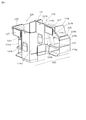
- FIG. 1 is a perspective view of the aircraft seat structure according to the first embodiment as viewed from the rear side.
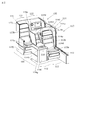
- FIG. 2 is a perspective view of the aircraft seat structure according to the present embodiment as viewed from the front side.
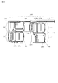
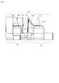
- FIG. 3 is a top view of the aircraft seat structure according to the present embodiment.
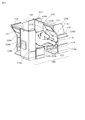
- FIG. 4 is a perspective view of the aircraft seat structure according to the present embodiment as viewed from the rear side.
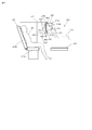
- FIG. 5 is a side view of the aircraft seat structure according to the present embodiment as viewed from the right side in the traveling direction.
- FIG. 6 is a side view showing the aircraft seat structure according to the second embodiment as viewed from the side.
- FIG. 7 is a side view showing the aircraft seat structure according to the second embodiment as viewed from the side.
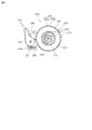
- FIG. 8 is a schematic view of the winding mechanism used in the present embodiment.
- FIG. 1 is a perspective view of the aircraft seat structure according to the first embodiment of the present invention as viewed from the rear side, and is shown in an upright state.
- FIG. 2 is a perspective view of the aircraft seat structure according to the present embodiment as viewed from the front side.
- FIG. 3 is a top view of the aircraft seat structure according to the present embodiment.
- FIG. 4 is a perspective view of the aircraft seat structure according to the present embodiment as viewed from the rear side, and is shown in a reclining state.
- first seat unit 110 and a second seat unit 120 coupled to the rear side of the first seat unit 110 will be described here as one unit.
- the first seat unit 110 includes a first seat area 111 including the seat 113 and a first side area 112 provided adjacent to the seat area 113 in the lateral direction.
- the seat 113 can be changed in form from an upright state in which the backrest stands up and a reclining state in which the backrest or the like tilts to approach a horizontal state.
- the second seat unit 120 includes a second seat area 121 including the seat 123 and a first side area 122 provided adjacent to the seat area 113 in the lateral direction.
- the seat 123 can be changed in form from an upright state in which the backrest stands up and a reclining state in which the backrest or the like tilts to approach a horizontal state.
- the first side region 112 of the first seat unit 110 is provided on the right side along the direction intersecting the seat 113 in the traveling direction of the aircraft, and the second seat is provided.
- the second side area 122 of the unit 120 is provided on the left side along the direction intersecting the seat 123 in the traveling direction of the aircraft.
- the first seat unit 110 and the second seat unit 120 have the same seat area and side area.
- the sheets 113 and 123 can have a common shape, and the parts can be standardized.
- the seat 113 has a seating portion 113a and a backrest 113b that can be tilted with respect to the seating portion 113a.
- the seat 123 has a seating portion 123a and a backrest 123b that is tiltable with respect to the seating portion 123a.
- a partition wall 114 integrally formed of a composite material is arranged between the first seat unit 110 and the second seat unit 120.
- the partition wall 114 includes a seat side surface portion 114a that surrounds the side portion of the seat 113, a seat back surface portion 114b that surrounds the back surface of the seat 113, and an intermediate wall 114c formed between the seat 113 and the first side region 112.
- a housing portion 114d forming the first side region 112 and a monitor mounting wall 114e (FIG. 2) extending from the housing portion 114d to the second seat unit 120 side are continuously provided.
- the inside of the housing portion 114d is isolated from the first seat unit 110 by the intermediate wall 114c, the front panel 114f, the side panel 114g, and the top panel 114h.
- the second seat unit 120 side of the housing portion 114d is open, and the internal space of the housing portion 114d can be accessed from here.
- the housing portion 114d is used as a partition, and the first side region 112 is joined with a part of the second seat region 121 inserted.
- a sound absorbing material or the like may be attached to the inner wall of the housing portion 114d.
- a footrest portion 115 supported at both ends is arranged on the intermediate wall 114c and the side panel 114g.
- the lower part of the footrest portion 115 can be used as a space for placing small luggage or the like.
- a side table 116 that can be used by passengers seated on the seat 113 is arranged on the upper panel 114h (FIG. 2) of the housing portion 114d.
- the monitor mounting wall 114e extends inclined from the upper end edge of the housing portion 114d on the second seat unit 120 side toward the second seat unit 120 side. Since the monitor mounting wall 114e is tilted toward the second seat unit 120, passengers using the first seat unit 110 do not feel oppressive.
- the back surface (lower surface) of the monitor mounting wall 114e is a slope 114i that is inclined so as to fall toward the second seat unit 120 side.
- the slope 114i is connected to the lower surface of the upper surface panel 114h of the housing portion 114d.
- a partition plate 114j is supported on the side edge of the monitor mounting wall 114e and extends in the same direction as the side panel 114g of the housing portion 114d.
- the inclination angle of the slope 114i is preferably within 45 degrees with respect to the horizontal plane.
- an upper edge of the monitor 117 with the screen facing the second seat unit 120 side is attached via a hinge (not shown).
- the monitor 117 can be manually or electrically displaced between the upright position shown in FIG. 1 and the tilted position shown in FIG. In the tilted position, the monitor 117 extends in the direction along the slope 114i.
- the monitor 117 When the monitor 117 is tilted to the upright position as shown in FIG. 1, a triangular tubular space is created between the monitor 117 and the slope 114i. For this reason, when the passenger's head falls forward and hits the monitor 117 when the aircraft shakes, the monitor 117 can be evacuated with a light force, thereby improving safety.
- the monitor 117 in the upright position is pushed from the second seat unit 120 side with a force equal to or higher than the threshold value, the monitor 117 is unlocked and automatically at the position shown in FIG. 4 by the force of the spring. The monitor 117 may be retracted until.
- a pocket 114m for accommodating headphones and the like, a light 114n for the first seat unit 110, and an accommodating portion 114p for accommodating an in-flight entertainment remote controller and the like are formed on the front surface of the monitor mounting wall 114e.
- a partition wall 124 integrally formed from a composite material is arranged between the second seat unit 120 and the seat unit (not shown) behind the second seat unit 120.
- the partition wall 124 having a shape mirror image of the partition wall 114 includes a seat side surface portion 124a surrounding the side portion of the seat 123, a seat back surface portion 124b surrounding the back surface of the seat 123, and the seat 123 and the second side region 122. It has an intermediate wall 124c (FIG. 2) formed between them, a housing portion 124d forming a second side region 122, and a monitor mounting wall 124e extending rearward from the housing portion 124d.
- the same configuration as that of the first seat unit 110 will not be duplicated.
- the housing portion 124d has the same configuration as the housing portion 114d, and the monitor mounting wall 124e has the same configuration as the monitor mounting wall 114e.
- a monitor 127 is tiltably mounted on the monitor mounting wall 124e.
- a passenger control unit PCU including a switch for changing the state is arranged below the side table 126 so as to face the seat 123 (FIG. 5).
- a similar passenger control unit is also arranged in the first seat unit 110.
- the seat 123 of the second seat unit 120 can be changed from a standing state to a reclining state by a drive mechanism (not shown) by operating the passenger control unit PCU.
- a drive mechanism for example, the technique of Special Table 2010-520117 can be used.
- the backrest 123b is angled at approximately 100 degrees with respect to the seating portion 123a.
- a passenger seated on the seat 123 in such a state can see the screen of the monitor 117 with his / her back supported by the backrest 123b.
- Passengers can also place their feet on the footrest 115.
- the passenger's face faces the monitor 117.
- the image displayed on the monitor 117 can be visually recognized naturally.
- the seat 123 when the seat 123 is changed to the reclining state, it is driven by a drive mechanism (not shown), and the seating portion 123a advances toward the housing portion 114d while the backrest 123b approaches the horizontal, and the footrest is placed as shown in FIG. It is in a state of being close to or in contact with the portion 115. In the reclining state, the backrest 123b, the seating portion 123a, and the footrest portion 115 are in a substantially flat state.
- the passenger PS can lie on the reclining seat 123, and the monitor 117 is placed at a position parallel to the slope 114i as shown in FIG. 4 by one's own hand or by operating the passenger control unit PCU. Can be displaced to.
- the face faces the monitor 117, so that the image displayed on the monitor 117 can be visually recognized naturally.
- the passenger PS can cross his legs or curl his head as shown in FIG. 4 without being disturbed by the monitor 117. You can take a relaxed posture such as tilting the club forward, and you can realize a comfortable flight.
- FIG. 6 and 7 are side views showing the aircraft seat structure according to the second embodiment as viewed from the side, and FIG. 6 shows the seat 123 of the second seat area in the upright state. , FIG. 7 shows the seat 123 of the second seat area in the reclining state.
- the same components as those in the above-described embodiment are designated by the same reference numerals, and duplicate description will be omitted.
- the monitor 117 is rotatably attached to the slope 114i of the first seat unit 110 via the rotation shaft 117a at the upper end. It is assumed that the monitor 117 is always urged clockwise in FIGS. 6 and 7 with the rotation shaft 117a as an axis by a spring (not shown) having a urging force weaker than that of the mainspring spring 234 described later.
- a locking device 210 is attached to the partition wall 114 near the lower end of the monitor 117.
- the locking device 210 swings with a swing shaft 211 extending in the direction perpendicular to the paper surface and swingable with respect to the partition wall 114, a swing plate 212 extending in the radial direction from the swing shaft 211, and swinging. It has locking portions 213 protruding upward from both ends of the plate 212.
- the end of the wire WR is connected to the lower end of the back surface of the monitor 117.
- the wire WR is connected to the winding mechanism 220 via pulleys PR1, PR2, PR3, and PR4 rotatably attached to the partition wall 114.
- the monitor 117 is urged clockwise by a spring (not shown)
- the tilting end shown by the dotted line in FIG. 6 or the solid line shown in FIG. 7 It will tilt to the upright position.
- FIG. 8 is a schematic view of the take-up mechanism 220.
- the winding mechanism 220 constituting the drive mechanism has a rotating portion 230 and a lever portion 240.
- the rotating portion 230 includes a fixed shaft 231 fixed to the partition wall 114, a toothed disk 232 rotating around the fixed shaft 231, a drum 233 coaxially connected to the toothed disk 232, and a fixed shaft 231 and a drum. It has a mainspring spring 234 that connects with 233.
- a large number of teeth 235 having a short slope 235a and a long slope 235b are formed adjacent to each other in the circumferential direction on the outer circumference of the toothed disk 232.
- the short slope 235a extends substantially along the radial direction of the toothed disc 232.
- the end of the wire WR is connected to the outer circumference of the drum 233, and the wire WR is wound around the outer circumference of the drum 233.
- the lever portion 240 has a lever shaft 241 fixed to the partition wall 114 and a lever (operation portion) 242 that can swing around the lever shaft 241.
- the lever 242 is formed with a claw portion 243 protruding toward the toothed disk 232 and a convex portion 244 protruding downward.
- the claw portion 243 can be engaged with the short slope 235a of the tooth 235 of the toothed disk 232.
- a spring 245 is arranged between the convex portion 244 and a part of the partition wall 114, and the convex portion 244 is pressed toward the contact locking portion 114s by the urging force of the spring 245.
- the toothed disk 232 and the drum 233 are urged counterclockwise by the spring 234 in FIG. 8, and in the free state, the claw portion 243 of the lever 242 is attached to the short slope 235a of the tooth 235 of the toothed disk 232.
- the toothed disk 232 is prevented from rotating by abutting
- the monitor inclination angle is set to zero (upright).
- Position when the monitor 117 is tilted toward the user US who visually recognizes the screen of the monitor 117, the monitor tilt angle is in the negative angle range, and when the monitor 117 is tilted away from the user US, the monitor tilt angle is set. Is in the regular angle range.
- the swing shaft 211 of the locking device 210 swings counterclockwise, and the locking portion 213 is located on the back surface of the monitor 117 in the upright position. It is designed to come into contact. This is called the standing position.
- the locking device 210 may be swung to the upright position by an actuator or the like interlocking with the seat 123, or the locking device 210 may be upright in response to the movement of the seat 123 by the link mechanism. It may be swung to a position.
- the wire WR can be freely pulled out, so that the operation of the user who pulls out the monitor 117 toward the front side is not hindered.
- the toothed disk 232 rotates counterclockwise due to the urging force of the spring 234, but the claw portion 243 engages with an arbitrary short slope 235a. The rotation of the drum 233 is locked so that the monitor 117 stays in that position.
- the user US tilts the lever 242 from the solid line position to the alternate long and short dash line position against the urging force of the spring 245.
- the claw portion 243 of the lever 242 disengages from the short slope 235a of the tooth 235 of the toothed disk 232, and the urging force of the mainspring 234 causes the toothed disk 232 and the drum 233 to counterclockwise in FIG. It starts to rotate around.
- the wire WR is pulled so that the lower end of the monitor 117 is pulled toward the slope 114i side, and the inclination angle of the monitor 117 approaches zero.
- the lever 242 When the user US releases the lever 242, the lever 242 returns to the original position by the urging force of the spring 245, and the claw portion 243 engages with the short slope 235a to rotate the toothed disk 232 and the drum 233. Stops and the monitor 117 stays in that position.
- the locking portion 213 of the locking device 210 When the user US keeps pulling the lever 242, the locking portion 213 of the locking device 210 finally hits the back surface of the monitor 117 to prevent further tilting, and the monitor 117 engages in a state where the tilt angle is zero. It will be stopped.
- the lever 242 can also be tilted by remote control using, for example, an electromagnetic solenoid.
- an electromagnetic solenoid For example, at the time of takeoff and landing of an aircraft, in principle, the seat 123 is returned to the upright state to ensure safety. At this time, the cabin attendant can operate the switches (not shown) to tilt the levers 242 of each seat all at once.
- the lever 242 is arranged at a position within reach of the user US lying on the seat 123.
- the toothed disk 232 is rotated counterclockwise in FIG. 8 by the urging force of the mainspring 234, the wire WR is pulled, and the tilt angle is conformal, as described above.
- the monitor 117 can be tilted in the direction of the range.
- the pulling of the wire WR is interrupted as described above and the monitor 117 stays in that position.
- the user US can visually recognize the screen of the monitor 117 at a desired monitor tilt angle in the conformal range.
- the monitor 117 eventually tilts to a position accommodated in the recess 114k of the slope 114i.
- the monitor 117 When the monitor 117 is housed in the recess 114k, further tilting is prevented, and the monitor 117 is locked at the monitor tilt angle (here, +35 degrees) which is the maximum value in the conformal range.
- the monitor tilt angle which is the maximum value in the conformal range, is preferably 30 degrees to 45 degrees in order to ensure the visibility of the monitor 117.
- the inclination angle ⁇ of the slope 114i with respect to the floor surface is equal to the maximum value of the monitor inclination angle in order to ensure effective use of space and improvement of design.
- the monitor 117 can be reached, and the monitor 117 can be grasped and returned to the upright position.
- the monitor 117 may be tiltable in two positions, an upright position and a tilt position, may be locked at a plurality of tilt positions between the upright position and the tilt position, or may be locked in a stepless position. It may be configured so that it can be displaced by and locked at an arbitrary position.
Landscapes
- Engineering & Computer Science (AREA)
- Aviation & Aerospace Engineering (AREA)
- Seats For Vehicles (AREA)
- Passenger Equipment (AREA)
- Chairs For Special Purposes, Such As Reclining Chairs (AREA)
Abstract
乗客の快適さを確保するとともに、客室内のスペースを有効活用できる航空機用シート構造体を提供する。航空機用シート構造体は、乗客が着席可能な第1のシート領域、及び前記第1のシート領域の長手方向に対して直交する方向に隣接する第1のサイド領域、を備えた第1のシートユニットと、乗客が着席可能な第2のシート領域、前記第2のシート領域の長手方向に対して直交する方向に隣接する第2のサイド領域、を備えた第2のシートユニットと、を有し、前記第1のサイド領域は、前記第1のシート領域に対し航空機の進行方向に交差する方向に沿って一方の側に設けられ、前記第2のサイド領域は、前記第2のシート領域に対し前記交差する方向に沿って他方の側に設けられており、前記第1のサイド領域に前記第2のシート領域の一部を挿入した状態で結合され、前記第1のサイド領域と前記第2のシート領域とは、隔壁で仕切られており、前記隔壁は、前記第2のシートユニット側に向かって傾いた斜面を有している。
Description
本発明は、航空機用シート構造体に関する。
航空機において、背もたれが起立した起立状態と、該背もたれ等が傾動して水平状態に近づくリクライニング状態と、を選択的に変更できるシート構造体が、ファーストクラスやビジネスクラス向け等のシートとして搭載されている。
このようなシート構造体の多くは、リクライニング可能なシートを壁状の部材等で仕切った空間内に配置したシートモジュール(座席ユニット)として構成される。
ここで、前側のシートと後側のシートとの間隔をあければ、使用できる空間が広がることから乗客の快適性は向上する一方で、航空機内スペースは有限であることから、搭載できるシートモジュール数、すなわち航空機の乗客定員の減少を招く。そこで、航空機の進行方向に対し、前側のシートと後側のシートとを左右に互い違いに配置したシート構成が、例えば特許文献1に開示されている。
かかる従来技術のシート構成によれば、前側のシートの脇の領域の下方に、後側のシートに着席する乗客が占有できる空間(footwell)を隔離して形成している。このため、例えば後側のシートを水平状態としてベッドとして使用する際には、乗客の脚を該空間に収納することができる。したがって、前側のシートと後側のシートとの間隔を広げなくても、乗客が脚を伸ばして楽な姿勢で横たわることができる。一方、該空間が前側のシートとは隔離されているため、前側のシートを利用する乗客は、後側シートの乗客の足の存在が気にならない。
ところで、乗客に快適なフライトを提供すべく、フライト中に映画などを鑑賞できるモニタ(ディスプレイ)を配備することが行われている。特許文献1に開示されたシートにおいては、後側のシート前方にて直立した前壁にモニタを設置することができる。かかる前壁は、前側のシートを利用する乗客の脇に位置している。
しかしながら、このように直立した前壁が、前側のシートを利用する乗客の脇に位置していると、この乗客の肩周りのスペースが制限され、圧迫感を覚える虞れがある。また、後側のシートに着席する乗客が足を収容する空間が水平方向に開口を持つ箱状であるため、足の出し入れがしにくいという問題もある。
そこで本発明は、乗客の快適さを確保するとともに、客室内のスペースを有効活用できる航空機用シート構造体を提供することにある。
上記の目的を達成するために、本発明による航空機用シート構造体は、
乗客が着席可能な第1のシート領域と、前記第1のシート領域の長手方向に対して直交する方向に隣接する第1のサイド領域と、を備えた第1のシートユニットと、
乗客が着席可能な第2のシート領域と、前記第2のシート領域の長手方向に対して直交する方向に隣接する第2のサイド領域と、を備えた第2のシートユニットと、を有し、
前記第1のサイド領域は、前記第1のシート領域に対し航空機の進行方向に交差する方向に沿って一方の側に設けられ、前記第2のサイド領域は、前記第2のシート領域に対し前記交差する方向に沿って他方の側に設けられており、
前記第1のサイド領域に前記第2のシート領域の一部を挿入した状態で結合され、前記第1のサイド領域と前記第2のシート領域とは、隔壁で仕切られており、
前記隔壁は、前記第2のシートユニット側に向かって傾いた斜面を有する。
本発明によれば、乗客の快適さを確保するとともに、客室内のスペースを有効活用できる。
図1は、本発明の第1の実施形態にかかる航空機用シート構造体の後方側から見た斜視図であり、起立状態で示している。図2は、本実施形態にかかる航空機用シート構造体の前方側から見た斜視図である。図3は、本実施形態にかかる航空機用シート構造体の上面図である。図4は、本実施形態にかかる航空機用シート構造体の後方側から見た斜視図であり、リクライニング状態で示している。
航空機用シート構造体100は、第1のシートユニット110と、当該第1のシートユニット110の後部側に結合された第2のシートユニット120と、をここでは1単位として説明する。
第1のシートユニット110は、シート113を含む第1のシート領域111と、シート領域113の横方向に隣接して設けられた第1のサイド領域112と、を含む。シート113は、背もたれが起立した起立状態と、該背もたれ等が傾動して水平状態に近づくリクライニング状態との形態変更が可能である。
同様に、第2のシートユニット120は、シート123を含む第2のシート領域121と、シート領域113の横方向に隣接して設けられた第1のサイド領域122と、を含む。シート123は、背もたれが起立した起立状態と、該背もたれ等が傾動して水平状態に近づくリクライニング状態との形態変更が可能である。
そして、図2、3に示すように、第1のシートユニット110の第1のサイド領域112は、シート113に対し航空機の進行方向に交差する方向に沿って右側に設けられ、第2のシートユニット120の第2のサイド領域122は、シート123に対し航空機の進行方向に交差する方向に沿って左側に設けられている。
このとき、第1のシートユニット110と第2のシートユニット120とは、それぞれのシート領域及びサイド領域を同一のサイズで作成することが好ましい。これにより、シート113,123を共通した形状とでき、部品の共通化を図れる。
シート113は、着座部113aと、着座部113aに対し傾動可能な背もたれ113bとを有する。同様に、シート123は、着座部123aと、着座部123aに対し傾動可能な背もたれ123bとを有する。
第1のシートユニット110と、第2のシートユニット120との間に、複合材から一体的に形成された隔壁114が配置されている。隔壁114は、シート113の側部を囲うシート側面部114aと、シート113の背面を囲うシート背面部114bと、シート113と第1のサイド領域112との間に形成された中間壁114cと、第1のサイド領域112を形成する筐体部114dと、筐体部114dから第2のシートユニット120側へと延在するモニタ取付壁114e(図2)と、を連設して有する。
筐体部114dの内部は、中間壁114cと、前面パネル114fと、側面パネル114gと、上面パネル114hとによって、第1のシートユニット110から隔離されている。しかし、筐体部114dの第2のシートユニット120側は開放されており、ここから筐体部114dの内部空間にアクセス可能となっている。換言すれば、筐体部114dを仕切りとし、第1のサイド領域112は第2のシート領域121の一部を挿入した状態で結合されている。筐体部114dの内壁に吸音材などを張設してもよい。
筐体部114dの内部には、中間壁114cと側面パネル114gとに両端支持された足置き部115が配置されている。足置き部115の下方は、小さな荷物などを置くスペースとして利用できる。
筐体部114dの上面パネル114h(図2)には、シート113に着席した乗客が使用できるサイドテーブル116が配置されている。
モニタ取付壁114eは、筐体部114dの第2のシートユニット120側の上端縁から、第2のシートユニット120側へと傾いて延在している。モニタ取付壁114eが、第2のシートユニット120に向かって傾いているので、第1のシートユニット110を利用する乗客は圧迫感を覚えない。
モニタ取付壁114eの背面(下面)は、第2のシートユニット120側に向かって倒れるよう傾いた斜面114iとなっている。斜面114iは、筐体部114dの上面パネル114hの下面とつながっている。モニタ取付壁114eの側縁に、仕切り板114jが支持されて、筐体部114dの側面パネル114gと同方向に延在している。斜面114iの傾き角は、水平面に対して45度以内であると好ましい。
モニタ取付壁114eの背面(下面)は、第2のシートユニット120側に向かって倒れるよう傾いた斜面114iとなっている。斜面114iは、筐体部114dの上面パネル114hの下面とつながっている。モニタ取付壁114eの側縁に、仕切り板114jが支持されて、筐体部114dの側面パネル114gと同方向に延在している。斜面114iの傾き角は、水平面に対して45度以内であると好ましい。
斜面114iの上端近傍には、第2のシートユニット120側に画面を向けたモニタ117の上縁が、不図示のヒンジを介して取り付けられている。斜面114iの上端近傍にモニタ117を取り付けることで、第2のシートユニット120を利用する乗客とモニタ画面との距離を近づけることができるため、小さな画面でも高精細の画像や映像を鑑賞できる。更にモニタ117は、手動又は電動により、図1に示す直立位置と図4に示す傾動位置との間で変位させることができる。傾動位置では、モニタ117は斜面114iに沿った方向に延在する。
モニタ117の傾動時に、モニタ117の背面の電子部品収容部が嵌合する角形の凹部114kを、斜面114iに設けてもよい(図1)。これによりモニタ117の画面と斜面114iとの段差を小さくできる。
モニタ117の傾動時に、モニタ117の背面の電子部品収容部が嵌合する角形の凹部114kを、斜面114iに設けてもよい(図1)。これによりモニタ117の画面と斜面114iとの段差を小さくできる。
モニタ117を図1に示すように直立位置へと傾動させたとき、モニタ117と斜面114iとの間には三角筒状の空間が生じる。このため、航空機が揺れた際などに、乗客の頭部が前に倒れてモニタ117に当たったときなど、モニタ117は軽い力で退避可能となっており、それにより安全性を高めている。なお、図示しないが、直立位置にあるモニタ117が第2のシートユニット120側から閾値以上の力で押された時、モニタ117のロックが外れスプリングの力で、自動的に図4に示す位置までモニタ117が退避するようにしてもよい。
図2において、モニタ取付壁114eの前面には、ヘッドホンなどを収納するポケット114m、第1のシートユニット110用のライト114n、インフライトエンターテイメントのリモコンなどを収容する収容部114pが形成されている。
一方、第2のシートユニット120と、その後方のシートユニット(不図示)との間に、複合材から一体的に形成された隔壁124が配置されている。隔壁114とは鏡像関係にある形状の隔壁124は、シート123の側部を囲うシート側面部124aと、シート123の背面を囲うシート背面部124bと、シート123と第2のサイド領域122との間に形成された中間壁124c(図2)と、第2のサイド領域122を形成する筐体部124dと、筐体部124dから後側へと延在するモニタ取付壁124eとを有する。尚、第1のシートユニット110と同様の構成については、重複する説明を省略する。
筐体部124dは、筐体部114dと同様の構成を有し、またモニタ取付壁124eは、モニタ取付壁114eと同様の構成を有する。モニタ取付壁124eには、モニタ127が傾動可能に取り付けられている。
シート123に座る乗客が鑑賞するモニタ117のオン/オフスイッチ、チャンネルを選択するスイッチ、音量を変更する摘み、モニタが電動で傾動する場合には傾動を行わせるスイッチ、シート123を起立状態又はリクライニング状態に変更するスイッチなどを備えたパッセンジャーコントロールユニットPCUが、サイドテーブル126の下方において、シート123に面するように配置されている(図5)。なお、同様のパッセンジャーコントロールユニットが、第1のシートユニット110にも配置されている。
シート123に座る乗客が鑑賞するモニタ117のオン/オフスイッチ、チャンネルを選択するスイッチ、音量を変更する摘み、モニタが電動で傾動する場合には傾動を行わせるスイッチ、シート123を起立状態又はリクライニング状態に変更するスイッチなどを備えたパッセンジャーコントロールユニットPCUが、サイドテーブル126の下方において、シート123に面するように配置されている(図5)。なお、同様のパッセンジャーコントロールユニットが、第1のシートユニット110にも配置されている。
第2のシートユニット120のシート123は、パッセンジャーコントロールユニットPCUを操作することにより、不図示の駆動機構により起立状態とリクライニング状態との形態変更が可能となっている。このような駆動機構は、例えば特表2010-520117号の技術を用いることができる。
より具体的に、シート123が起立状態にあるとき、着座部123aに対して、背もたれ123bが大凡100度で角度付された状態にある。かかる状態でシート123に着座した乗客は、背もたれ123bに背中を支えられた状態でモニタ117の画面を見ることができる。また乗客は、足を足置き部115に置くこともできる。
このとき、例えば乗客自らの手で或いはパッセンジャーコントロールユニットPCUを操作することによりモニタ117を変位させて、図1に示すように直立位置にすることにより、乗客の顔がモニタ117に正対するため、モニタ117に表示される画像を自然に視認できる。
一方、シート123をリクライニング状態に変更する場合、不図示の駆動機構に駆動されて、背もたれ123bが水平に近づきつつ着座部123aが筐体部114d側へ前進し、図4に示すように足置き部115に近接もしくは当接した状態になる。リクライニング状態では、背もたれ123b、着座部123a、及び足置き部115は、略フラットな状態になる。
このとき、乗客PSは、リクライニング状態にしたシート123に横たわることができ、更に自らの手で或いはパッセンジャーコントロールユニットPCUを操作することによりモニタ117を、図4に示すように斜面114iに平行な位置まで変位させることができる。これにより、乗客PSが横たわった状態でも、その顔がモニタ117に正対するため、モニタ117に表示される画像を自然に視認できる。
また、傾動位置にあるモニタ117及び斜面114iの下方には広いスペースが生じるので、乗客PSはモニタ117に邪魔されることなく、図4に示すように足を組んだり、或いは体を丸めて頭部を前に倒すなど寛いだ姿勢をとることができ、快適なフライトを実現できる。
図6、7は、第2の実施形態にかかる航空機用シート構造体を側面から見た状態で示す側面図であり、図6は、起立状態とされた第2のシート領域のシート123を示し、図7は、リクライニング状態とされた第2のシート領域のシート123を示している。なお、上述した実施形態と同様の構成については、同じ符号を付して重複説明を省略する。
本実施形態において、モニタ117は、上端の回転軸117aを介して、第1のシートユニット110の斜面114iに回動可能に取り付けられている。モニタ117は、後述するゼンマイばね234より弱い付勢力のスプリング(不図示)により、回転軸117aを軸として図6,7で時計回りに常に付勢されているものとする。モニタ117の下端近傍には、係止装置210が隔壁114に取り付けられている。
係止装置210は、隔壁114に対して紙面垂直方向に延在し揺動可能となっている揺動軸211と、揺動軸211から径方向に延在する揺動板212と、揺動板212の両端から上方に突出した係止部213とを有する。
モニタ117の背面下端には、ワイヤWRの端部が連結されている。ワイヤWRは、隔壁114に回転可能に取り付けられたプーリPR1,PR2,PR3,PR4を介して、巻き取り機構220に連結されている。上述したように、モニタ117は不図示のスプリングにより時計回りに付勢されているため、仮にワイヤWRの張力を付与しなければ、図6に点線で示す傾動端、または図7に実線で示す直立位置まで傾動することとなる。
図8は、巻き取り機構220の概略図である。図8において、駆動機構を構成する巻き取り機構220は、回転部230と、レバー部240とを有する。回転部230は、隔壁114に固定された固定軸231と、固定軸231回りに回転する歯付き円盤232と、歯付き円盤232に対して同軸に連結されたドラム233と、固定軸231とドラム233とを連結するゼンマイばね234とを有する。
歯付き円盤232の外周には、短斜面235aと長斜面235bとを備えた多数の歯235が周方向に隣接して形成されている。短斜面235aは、歯付き円盤232の放射方向に略沿って延在する。ドラム233の外周には、ワイヤWRの端部が連結され、ワイヤWRはドラム233の外周に巻かれている。
レバー部240は、隔壁114に固定されたレバー軸241と、レバー軸241の周囲で揺動可能なレバー(操作部)242とを有する。レバー242には、歯付き円盤232に向かって突き出した爪部243と、下方に突出した凸部244とが形成されている。爪部243は、歯付き円盤232の歯235の短斜面235aに係合可能となっている。凸部244と隔壁114の一部との間に、スプリング245が配置されており、スプリング245の付勢力により、凸部244が当接係止部114sに向かって押圧されている。歯付き円盤232及びドラム233は、ゼンマイばね234により図8で反時計回りに付勢されており、自由状態では、レバー242の爪部243が、歯付き円盤232の歯235の短斜面235aに当接することで、歯付き円盤232は回動を阻止されている。
次に、本実施形態の動作について説明する。ここで、モニタ117の角度に関して、図6,7の実線で示すように、モニタ117の軸線が鉛直方向(ここでは航空機の床に垂直な方向)にあるときを、モニタ傾斜角をゼロ(直立位置)とし、モニタ117の画面を視認するユーザーUSの側にモニタ117が傾斜した場合、モニタ傾斜角が負角範囲であるとし、ユーザーUSから離れる側にモニタ117が傾斜した場合、モニタ傾斜角が正角範囲であるとする。
まず図6に示すように、シート123が起立状態にあるときは、係止装置210の揺動軸211が反時計回りに揺動し、直立位置にあるモニタ117の背面に係止部213が当接するようになっている。これを起立位置という。係止装置210は、シート123が起立状態に移動させられたとき、それに連動するアクチュエータ等によって起立位置へと揺動させられてもよいし、あるいはリンク機構によりシート123の移動に応じて、起立位置へと揺動させられてもよい。
かかる状態では、ユーザーUSが自らの手でモニタ117を把持して手前側に引くことでモニタ117が回転軸117a回りに傾動し、それにより最も見やすい位置へと変位させることができる。このとき、モニタ117が傾動可能なモニタ傾斜角を負角範囲(例えば0~-30度)とすることで、ユーザーUSの体格に応じて、最適な視聴を実現することができる。なお、モニタ117は、負角範囲の最大位置で不図示のストッパに当接して、それ以上の傾動が阻止される。
モニタ117を手前側に揺動させると、ワイヤWRが引っ張られ、図8に示す巻き取り機構220のドラム233が時計回りに回動する。このとき、ゼンマイばね234の付勢力に抗してドラム233とともに歯付き円盤232も時計回りに回動し、レバー242の爪部243は歯235の長斜面235bに沿って摺動する。摺動する際に爪部243は長斜面235bから押されるが、一つの長斜面235bを通過するたびに凸部244がスプリング245を圧縮しながら、レバー242が図8に一点鎖線で示すように傾動し、ドラム233の回動を許容する。これによりワイヤWRを自由に引き出すことができるため、モニタ117を手前側に引き出すユーザーの操作を阻害することはない。また、ユーザーUSが手を離すと、ゼンマイばね234の付勢力により歯付き円盤232が反時計回りに回動することになるが、爪部243が任意の短斜面235aに係合することにより、ドラム233の回動が係止されるため、モニタ117はその位置に留まる。
一方、モニタ117を元の位置へと戻したい場合、ユーザーUSは、スプリング245の付勢力に抗してレバー242を実線の位置から一点鎖線の位置へと傾動させる。レバー242が傾動すると、レバー242の爪部243が、歯付き円盤232の歯235の短斜面235aから係脱し、ゼンマイばね234の付勢力によって、歯付き円盤232及びドラム233は図8で反時計回りに回転し始める。これによりワイヤWRが引っ張られて、モニタ117の下端を斜面114i側へと引き寄せるようにし、モニタ117の傾斜角はゼロに近づく。ユーザーUSがレバー242から手を離すと、スプリング245の付勢力でレバー242が元の位置へ復帰し、爪部243が短斜面235aに係合することで、歯付き円盤232及びドラム233の回転が停止し、モニタ117はその位置に留まる。ユーザーUSがレバー242を引き続けると、最終的に係止装置210の係止部213がモニタ117の背面に当たることで、それ以上の傾動が阻止され、モニタ117は傾斜角がゼロの状態で係止されることとなる。
なお、レバー242を例えば電磁ソレノイド等によって、遠隔操作で傾動させることもできる。例えば航空機の離着陸時には、安全確保のため原則的にシート123を起立状態に戻すこととなる。このとき、キャビンアテンダントが不図示のスイッチを操作することで、各シートのレバー242を一斉に傾動させることができる。
次に図7に示すように、シート123がリクライニング状態にあるときは、係止装置210の揺動軸211が、時計回りに揺動し、係止部213が直立位置にあるモニタ117の正面に当接するようになっている。これをリクライニング位置という。
リクライニング状態にあるシート123の横たわるユーザーUSが、直立位置にあるモニタ117の画面を視認しようとすると、かかる画面を見上げることとなり、視認が困難となることが多い。しかしながら、モニタ117を傾動させるためにわざわざ起き上がらなければならないとすると、ユーザーUSの負担を招く。本実施形態においては、シート123に横たわったユーザーUSの手の届く位置に、レバー242を配置している。
ユーザーUSがレバー242を傾動させると、上述と同様に、ゼンマイばね234の付勢力によって、歯付き円盤232が図8で反時計回りに回転し、ワイヤWRが引っ張られて、傾斜角が正角範囲となる方向にモニタ117を傾動させることができる。ユーザーUSがレバー242から手を離すと、上述したようにワイヤWRの引張が中断され、モニタ117はその位置に留まる。これによりユーザーUSは、正角範囲である所望のモニタ傾斜角でモニタ117の画面を視認できる。ユーザーUSがレバー242を引き続けると、最終的にモニタ117は、斜面114iの凹部114kに収容される位置へと傾動する。
モニタ117が凹部114kに収容されると、それ以上の傾動が阻止され、モニタ117は、正角範囲の最大値となるモニタ傾斜角(ここでは+35度)で係止されることとなる。正角範囲の最大値であるモニタ傾斜角は、モニタ117の視認性を確保するためには、30度~45度であると好ましい。また、斜面114iの床面に対する傾斜角θは、スペースの有効活用とデザイン性の向上を確保すべく、モニタ傾斜角の最大値と等しくすることが好ましい。
ユーザーUSは、シート123を起立状態に戻すときに自ら起き上がるため、モニタ117に手が届くようになり、モニタ117を把持して直立位置へと戻すことができる。
以上、本実施形態による航空機用シート構造体を説明したが、本発明は上記の具体例に限定されるものではなく、種々の改変を施すことができる。例えば、モニタ117は直立位置と傾動位置との2ポジションで傾動可能としてもよいし、直立位置と傾動位置との間における複数の傾動位置で係止されるようにしてもよいし、或いは無段階で変位でき任意の位置で係止されるように構成してもよい。
10 航空機、100 航空機用シート構造体、110 第1のシートユニット、120 第2のシートユニット、111、121 シート領域、112、122 サイド領域、113、123 シート、114、124 隔壁、モニタ 117,127、210 係止装置、220 巻き取り機構
Claims (11)
- 乗客が着席可能な第1のシート領域と、前記第1のシート領域の長手方向に対して直交する方向に隣接する第1のサイド領域と、を備えた第1のシートユニットと、
乗客が着席可能な第2のシート領域と、前記第2のシート領域の長手方向に対して直交する方向に隣接する第2のサイド領域と、を備えた第2のシートユニットと、を有し、
前記第1のサイド領域は、前記第1のシート領域に対し航空機の進行方向に交差する方向に沿って一方の側に設けられ、前記第2のサイド領域は、前記第2のシート領域に対し前記交差する方向に沿って他方の側に設けられており、
前記第1のサイド領域に前記第2のシート領域の一部を挿入した状態で結合され、前記第1のサイド領域と前記第2のシート領域とは、隔壁で仕切られており、
前記隔壁は、前記第2のシートユニット側に向かって傾いた斜面を有している、
ことを特徴とする航空機用のシート構造体。 - 前記斜面にモニタが傾動可能に取り付けられている、
ことを特徴とする請求項1に記載の航空機用のシート構造体。 - 前記隔壁は、前記第1のサイド領域と前記第2のシート領域とを仕切る筐体部を有し、前記斜面は前記筐体部から前記第2のシートユニット側に向かって延在している取付壁の背面である、
ことを特徴とする請求項2に記載の航空機用のシート構造体。 - 前記筐体部内には、足置き部が形成されている、
ことを特徴とする請求項3に記載の航空機用のシート構造体。 - 前記第2のシート領域のシートは、起立状態とリクライニング状態との形態変更が可能であり、前記モニタは、前記起立状態に対応した傾動位置と、前記リクライニング状態に対応した傾動位置との間で変位可能である、
ことを特徴とする請求項2~4のいずれか1項に記載の航空機用のシート構造体。 - 前記モニタを、前記起立状態に対応した傾動位置に変位させたとき、前記モニタと前記斜面との間に空間が形成され、前記モニタを前記リクライニング状態に対応した傾動位置に変位させたとき、前記モニタは前記斜面に沿った方向に延在する、
ことを特徴とする請求項5に記載の航空機用のシート構造体。 - 前記第2のシート領域のシートが起立状態であるとき、前記モニタは負角範囲で傾動可能であり、前記第2のシート領域のシートがリクライニング状態であるとき、前記モニタは正角範囲で傾動可能である、
ことを特徴とする請求項5または6に記載の航空機用のシート構造体。 - 前記第2のシート領域のシートが起立状態であるとき、前記モニタの背面に当接可能となり、前記第2のシート領域のシートがリクライニング状態であるとき、前記モニタの正面に当接可能となる係止部を有する、
ことを特徴とする請求項5~7のいずれか一項に記載の航空機用のシート構造体。 - 前記モニタを所定位置へと傾動させる駆動機構を備える、
ことを特徴とする請求項5~8のいずれか一項に記載の航空機用のシート構造体。 - 前記駆動機構の操作部は、リクライニング状態のシートに横たわるユーザーの手の届く位置に配置されている、
ことを特徴とする請求項9に記載の航空機用のシート構造体。 - 前記斜面は、前記モニタの一部を収容する凹部を有している、
ことを特徴とする請求項2~10のいずれか一項に記載の航空機用のシート構造体。
Priority Applications (3)
| Application Number | Priority Date | Filing Date | Title |
|---|---|---|---|
| US17/440,782 US11731764B2 (en) | 2019-03-27 | 2020-03-13 | Aircraft seat structure |
| EP20779709.3A EP3950504A4 (en) | 2019-03-27 | 2020-03-13 | AIRCRAFT SEAT STRUCTURE |
| JP2020552432A JP6949245B2 (ja) | 2019-03-27 | 2020-03-13 | 航空機用シート構造体 |
Applications Claiming Priority (2)
| Application Number | Priority Date | Filing Date | Title |
|---|---|---|---|
| JP2019-059826 | 2019-03-27 | ||
| JP2019059826 | 2019-03-27 |
Publications (1)
| Publication Number | Publication Date |
|---|---|
| WO2020195945A1 true WO2020195945A1 (ja) | 2020-10-01 |
Family
ID=72611441
Family Applications (1)
| Application Number | Title | Priority Date | Filing Date |
|---|---|---|---|
| PCT/JP2020/011075 WO2020195945A1 (ja) | 2019-03-27 | 2020-03-13 | 航空機用シート構造体 |
Country Status (4)
| Country | Link |
|---|---|
| US (1) | US11731764B2 (ja) |
| EP (1) | EP3950504A4 (ja) |
| JP (1) | JP6949245B2 (ja) |
| WO (1) | WO2020195945A1 (ja) |
Families Citing this family (6)
| Publication number | Priority date | Publication date | Assignee | Title |
|---|---|---|---|---|
| GB2586043B (en) * | 2019-07-31 | 2023-05-10 | Safran Seats Gb Ltd | Aircraft passenger seat unit with movable panel |
| DE102020108436A1 (de) * | 2020-03-26 | 2021-09-30 | Recaro Aircraft Seating Gmbh & Co. Kg | Flugzeugsitzanordnung |
| USD989500S1 (en) * | 2020-09-24 | 2023-06-20 | Panasonic Intellectual Property Management Co., Ltd. | Combined transmissive display and airplane seat unit |
| USD990904S1 (en) * | 2020-09-24 | 2023-07-04 | Panasonic Intellectual Property Management Co., Ltd. | Combined transmissive display and airplane seat unit |
| USD984155S1 (en) * | 2020-09-24 | 2023-04-25 | Panasonic Intellectual Property Management Co., Ltd. | Combined transmissive display and airplane seat unit |
| USD990181S1 (en) * | 2020-09-24 | 2023-06-27 | Panasonic Intellectual Property Management Co., Ltd. | Combined transmissive display and airplane seat unit |
Citations (6)
| Publication number | Priority date | Publication date | Assignee | Title |
|---|---|---|---|---|
| WO2005020117A1 (fr) | 2003-08-26 | 2005-03-03 | Bazenov Vladimir Aleksandrovic | Procede de transmission et de traitement de donnees dans le cadre des competitions dans le domaine des jeux intellectuels entre plusieurs participants distants et systeme correspondant |
| JP2014511798A (ja) * | 2011-04-15 | 2014-05-19 | ゾディアック シーツ フランス | 乗客用座席の配置 |
| US20160083094A1 (en) * | 2013-05-07 | 2016-03-24 | Recaro Aircraft Seating Gmbh & Co. Kg | Aircraft seat |
| JP2016540674A (ja) * | 2013-10-24 | 2016-12-28 | ゾディアック シート シェルズ ユーエス エルエルシー | 輸送機器の乗客室のための座席ユニット |
| WO2017168746A1 (ja) | 2016-04-01 | 2017-10-05 | 株式会社ジャムコ | 航空機用シート構造体 |
| EP3446977A1 (en) * | 2012-03-16 | 2019-02-27 | Zodiac Seats UK Limited | High density aircraft seat arrangement |
Family Cites Families (6)
| Publication number | Priority date | Publication date | Assignee | Title |
|---|---|---|---|---|
| US6227489B1 (en) * | 1998-05-15 | 2001-05-08 | Koito Industries, Ltd. | Aircraft seat apparatus |
| JP2008279155A (ja) | 2007-05-14 | 2008-11-20 | Panasonic Corp | 画像表示装置 |
| GB2490095B (en) | 2011-04-01 | 2017-05-10 | Zodiac Seats Uk Ltd | Aircraft seat arrangement including table |
| GB2523309B (en) * | 2014-02-12 | 2015-12-23 | British Airways Plc | Aircraft passenger seating arrangements |
| FR3049578B1 (fr) * | 2016-03-31 | 2019-08-16 | Stelia Aerospace | Ensemble de sieges a fauteuils agences en quinconce |
| EP3873776B1 (fr) | 2018-11-02 | 2023-07-05 | Style & Design Group | Unite de siege passager pour une cabine d'aeronef |
-
2020
- 2020-03-13 WO PCT/JP2020/011075 patent/WO2020195945A1/ja unknown
- 2020-03-13 EP EP20779709.3A patent/EP3950504A4/en active Pending
- 2020-03-13 JP JP2020552432A patent/JP6949245B2/ja active Active
- 2020-03-13 US US17/440,782 patent/US11731764B2/en active Active
Patent Citations (6)
| Publication number | Priority date | Publication date | Assignee | Title |
|---|---|---|---|---|
| WO2005020117A1 (fr) | 2003-08-26 | 2005-03-03 | Bazenov Vladimir Aleksandrovic | Procede de transmission et de traitement de donnees dans le cadre des competitions dans le domaine des jeux intellectuels entre plusieurs participants distants et systeme correspondant |
| JP2014511798A (ja) * | 2011-04-15 | 2014-05-19 | ゾディアック シーツ フランス | 乗客用座席の配置 |
| EP3446977A1 (en) * | 2012-03-16 | 2019-02-27 | Zodiac Seats UK Limited | High density aircraft seat arrangement |
| US20160083094A1 (en) * | 2013-05-07 | 2016-03-24 | Recaro Aircraft Seating Gmbh & Co. Kg | Aircraft seat |
| JP2016540674A (ja) * | 2013-10-24 | 2016-12-28 | ゾディアック シート シェルズ ユーエス エルエルシー | 輸送機器の乗客室のための座席ユニット |
| WO2017168746A1 (ja) | 2016-04-01 | 2017-10-05 | 株式会社ジャムコ | 航空機用シート構造体 |
Also Published As
| Publication number | Publication date |
|---|---|
| JPWO2020195945A1 (ja) | 2021-04-30 |
| JP6949245B2 (ja) | 2021-10-13 |
| EP3950504A4 (en) | 2022-11-23 |
| US11731764B2 (en) | 2023-08-22 |
| EP3950504A1 (en) | 2022-02-09 |
| US20220161929A1 (en) | 2022-05-26 |
Similar Documents
| Publication | Publication Date | Title |
|---|---|---|
| WO2020195945A1 (ja) | 航空機用シート構造体 | |
| JP3990986B2 (ja) | 調節可能なシート | |
| JP5248325B2 (ja) | 航空機の乗客用座席 | |
| EP3653505B1 (en) | Recliner sofa system for economy class seat | |
| JP7097386B2 (ja) | 2つの座席ユニット間の通路の閉鎖装置 | |
| US8297554B2 (en) | Arrangement of a first and a second furnishing | |
| US10773626B2 (en) | Adjustable headrest enabling sideward leaning and seclusion | |
| JP2008074398A (ja) | シートユニット | |
| EP3873776B1 (fr) | Unite de siege passager pour une cabine d'aeronef | |
| EP3393906B1 (en) | Passenger seat having a displaceable seat element | |
| CA2884688C (en) | Aircraft sideboard | |
| JP2001138998A (ja) | 航空機用座席装置 | |
| JP3601776B2 (ja) | 航空機用座席装置 | |
| US20120280541A1 (en) | Retractable passenger seat | |
| JP3336454B2 (ja) | 航空機用座席装置 | |
| US20150314713A1 (en) | Vehicle Seat | |
| JP6470035B2 (ja) | 座席用テーブル装置 | |
| JP2000033900A (ja) | 航空機用座席装置 | |
| JP2006081792A (ja) | 航空機用座席装置 | |
| JP2003267102A (ja) | 二人掛け跳上式座席 | |
| JP4278670B2 (ja) | 車両用コンソール装置 | |
| WO2021008974A1 (fr) | Arrangements de sièges, notamment pour une cabine d'avion | |
| JP2018103901A (ja) | 座席装置 | |
| JP2002137665A (ja) | 折畳座席、これを構成するための座部クッション、及び折畳座席を設置した乗物 | |
| JP2001104090A (ja) | 乗物用座席装置 |
Legal Events
| Date | Code | Title | Description |
|---|---|---|---|
| ENP | Entry into the national phase |
Ref document number: 2020552432 Country of ref document: JP Kind code of ref document: A |
|
| 121 | Ep: the epo has been informed by wipo that ep was designated in this application |
Ref document number: 20779709 Country of ref document: EP Kind code of ref document: A1 |
|
| NENP | Non-entry into the national phase |
Ref country code: DE |
|
| ENP | Entry into the national phase |
Ref document number: 2020779709 Country of ref document: EP Effective date: 20211027 |