WO2020195772A1 - モータおよび電動ポンプ - Google Patents
モータおよび電動ポンプ Download PDFInfo
- Publication number
- WO2020195772A1 WO2020195772A1 PCT/JP2020/010198 JP2020010198W WO2020195772A1 WO 2020195772 A1 WO2020195772 A1 WO 2020195772A1 JP 2020010198 W JP2020010198 W JP 2020010198W WO 2020195772 A1 WO2020195772 A1 WO 2020195772A1
- Authority
- WO
- WIPO (PCT)
- Prior art keywords
- bearing
- output side
- motor
- opening
- wall portion
- Prior art date
- Legal status (The legal status is an assumption and is not a legal conclusion. Google has not performed a legal analysis and makes no representation as to the accuracy of the status listed.)
- Ceased
Links
Images



Classifications
-
- F—MECHANICAL ENGINEERING; LIGHTING; HEATING; WEAPONS; BLASTING
- F04—POSITIVE - DISPLACEMENT MACHINES FOR LIQUIDS; PUMPS FOR LIQUIDS OR ELASTIC FLUIDS
- F04D—NON-POSITIVE-DISPLACEMENT PUMPS
- F04D29/00—Details, component parts, or accessories
-
- H—ELECTRICITY
- H02—GENERATION; CONVERSION OR DISTRIBUTION OF ELECTRIC POWER
- H02K—DYNAMO-ELECTRIC MACHINES
- H02K5/00—Casings; Enclosures; Supports
- H02K5/04—Casings or enclosures characterised by the shape, form or construction thereof
- H02K5/08—Insulating casings
-
- H—ELECTRICITY
- H02—GENERATION; CONVERSION OR DISTRIBUTION OF ELECTRIC POWER
- H02K—DYNAMO-ELECTRIC MACHINES
- H02K5/00—Casings; Enclosures; Supports
- H02K5/04—Casings or enclosures characterised by the shape, form or construction thereof
- H02K5/16—Means for supporting bearings, e.g. insulating supports or means for fitting bearings in the bearing-shields
- H02K5/173—Means for supporting bearings, e.g. insulating supports or means for fitting bearings in the bearing-shields using bearings with rolling contact, e.g. ball bearings
Definitions
- the present invention relates to a motor used for a pump and an electric pump provided with the motor.
- the opening requires a depth corresponding to the axial dimension of the bearing, so that the end of the housing on the output side occupies a large space. , There is a problem that the dimension in the axial direction of the motor increases.
- an object of the present invention is to provide a motor and a pump capable of holding a bearing in a space having a short dimension in the axial direction.
- the motor according to the present invention includes a stator, a rotor arranged inside the stator, and a first wall portion that covers the stator from the output side, and the first wall portion of the first wall portion.
- a housing provided with a first opening on the rotation center axis of the rotor, a first bearing that rotatably supports the rotation axis of the rotor on the output side, and a first cylinder portion that holds the first bearing inside.
- a first bearing holder having a first flange portion that is press-fitted and fixed to the inside of the first opening portion by expanding the diameter at the output side end portion of the first cylinder portion. ..
- the first bearing that supports the rotating shaft on the output side is held by the first wall portion of the housing via the first bearing holder, and the first bearing holder holds the first bearing inside.
- the first flange portion whose diameter is expanded at the output side end portion of the first cylinder portion is press-fitted and fixed to the first opening portion of the first wall portion. Therefore, as compared with the structure in which the first bearing is press-fitted and fixed directly to the first opening, or the structure in which the entire first bearing holder is press-fitted and fixed to the first opening, the first bearing is placed in a space having a shorter axial dimension. Since one bearing can be held, the first wall portion can be made thin. Therefore, the dimension in the direction of the rotation center axis of the motor can be compressed.
- the first opening has an inner diameter smaller than that of the first hole portion and the first hole portion into which the outer peripheral surface of the first flange portion is press-fitted, and communicates with the first hole portion on the counter-output side. It is possible to adopt a mode in which the second hole portion is provided, and the step portion between the first hole portion and the second hole portion supports the first flange portion from the counter-output side. According to this aspect, even when the first flange portion is press-fitted into the first opening, the first bearing holder can be fixed to the housing in a stable state.
- the thickness of the first flange portion in the direction of the rotation center axis is thinner than the length of the first cylinder portion in the direction of the rotation center axis. According to this aspect, since the first wall portion can be made thin, the dimensions in the direction of the rotation center axis of the motor can be compressed.
- the inner peripheral surface of the first opening is provided with a communication portion extending in the direction of the rotation center axis to communicate the output side and the counter-output side of the first flange portion.
- a communication portion extending in the direction of the rotation center axis to communicate the output side and the counter-output side of the first flange portion.
- the first bearing may be a ball bearing. According to such an aspect, it is possible to cope with high-speed rotation of the rotor.
- the housing is a resin-sealed body molded so as to cover the stator.
- the housing includes a second wall portion that covers the stator from the counter-output side, and a second opening is provided on the rotation center axis of the second wall portion.
- a mode in which a second bearing holder in which a second bearing that rotatably supports the rotating shaft on the counter-output side is arranged inside can be adopted as the portion.
- the second bearing holder is expanded in diameter at the second cylinder portion in which the second bearing is arranged inside and the output side end portion of the second cylinder portion so as to be around the second opening. It is possible to adopt an embodiment having a second flange portion fixed to the second wall portion by a screw and a bottom plate portion that closes the opening on the opposite output side of the second cylinder portion. According to this aspect, the coaxiality of the second bearing holder with respect to the rotation center axis can be increased as compared with the case where the second bearing holder is integrated with the housing by insert molding.
- the second bearing may be a ball bearing. According to such an aspect, it is possible to cope with high-speed rotation of the rotor.
- the motor according to the present invention can be used for an electric pump.
- the electric pump is arranged in a pump case that covers the first wall portion and forms a pump chamber inside, and the rotary shaft. It is characterized by having an impeller connected to and.
- the impeller can adopt a mode in which the impeller is connected to the rotating shaft by a screw.
- the rotating shaft and the impeller are fixed by press fitting, burrs and powder are less likely to occur.
- the rotary shaft and the impeller are fixed by press fitting, when the rotary shaft and the impeller are connected, it is not necessary to support the rotary shaft from the counter-output side, so that the rotary shaft and the impeller can be easily connected. ..
- the first bearing that supports the rotating shaft on the output side is held by the first wall portion of the housing via the first bearing holder, and the first bearing holder holds the first bearing inside.
- the first flange portion whose diameter is expanded at the output side end portion of the first cylinder portion is press-fitted and fixed to the first opening portion of the first wall portion. Therefore, the first wall portion can be made thinner than the structure in which the first bearing is press-fitted and fixed directly to the first opening or the structure in which the entire first bearing holder is press-fitted and fixed to the first opening. .. Therefore, the dimension in the direction of the rotation center axis of the motor can be compressed.
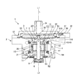
- FIG. 3 is a cross-sectional view of the electric pump shown in FIG.
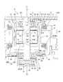
- FIG. 3 is a cross-sectional view of a main part of the motor shown in FIG.
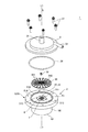
- An exploded perspective view of the motor shown in FIG. Explanatory drawing of the 1st bearing holder, the 2nd bearing holder and the like shown in FIG.
- reference numeral L indicates an axial direction of the motor 2 (rotational axis direction of the rotating shaft 20).
- the output side L1 is the side where the rotation shaft 20 outputs rotation (the side where the impeller 35 is arranged)
- the counter-output side L2 is the side where the impeller 35 is arranged. It is the opposite side to the side where it is placed.
- the direction orthogonal to the axis L is the radial direction
- the circumference of the axis L is the circumferential direction.
- FIG. 1 is a perspective view of an electric pump 1 provided with a motor 2 to which the present invention is applied.
- FIG. 2 is a cross-sectional view of the electric pump 1 shown in FIG.
- FIG. 3 is an exploded perspective view of the electric pump 1 shown in FIG.
- the electric pump 1 shown in FIGS. 1, 2 and 3 has a pump case 3 forming a pump chamber 30 between the motor 2 and the motor 2, and an impeller 35 attached to the rotating shaft 20 of the motor 2.
- the impeller 35 is located inside the pump chamber 30.
- the impeller 35 is a resin molded product having a disc portion 350 and a ridge portion 351 formed in a radial pattern on the surface of the output side L1 of the disc portion 350, and the ridge portion 351 is from the inside in the radial direction. It extends radially outward.
- the pump case 3 is provided with a fluid suction port 31 and a fluid discharge port 32. When the motor 2 is driven to rotate the impeller 35 around the axis L, the fluid sucked from the suction port 31 is discharged from the discharge port 32 via the pump chamber 30.
- the suction port 31 is provided in the pump case 3 at a position overlapping the axis L of the rotating shaft 20 of the motor 2, and the discharge port 32 is provided outside the rotating shaft 20 in the radial direction.
- the motor 2 is a three-phase DC brushless motor, and includes a rotor 10, a stator 4 that faces the rotor 10 on the outer side in the radial direction, and a housing 5 that houses the rotor 10 and the stator 4.
- the housing 5 is made of a resin sealant 50 molded so as to cover the stator 4.
- the resin sealing body 50 is formed by BMC (Bulk Molding Compound).
- the stator 4 has a stator core 41 made of a magnetic material, an insulator 42 made of an insulating resin or the like covering the stator core 41, and a lead wire 43 for forming a coil.
- the stator core 41 is a laminated core formed by laminating thin magnetic plates.
- the stator core 41 includes a tubular core body and a plurality of salient poles protruding inward in the radial direction from the core body, and the lead wire 43 is wound around the salient poles via an insulator 42.
- the coils 45 of each phase (U phase, V phase, and W phase) are formed.
- the housing 5 includes a first wall portion 51 that covers the stator 4 from the output side L1, a second wall portion 52 that covers the stator 4 from the counter-output side L2, and a third wall portion 53 that covers the stator 4 from the inside in the radial direction. It has a fourth wall portion 54 that covers the stator 4 from the outside in the radial direction.
- the first wall portion 51 projects radially outward from the outer peripheral surface of the third wall portion 53 in a flange shape.
- the pump case 3 is superposed on the first wall portion 51 of the output side L1 via the O-ring 36, and in this state, the pump case 3 is fixed to the first wall portion 51 by the bolt 37.
- a pump chamber 30 in which the impeller 35 is arranged is formed between the first wall portion 51 and the pump case 3.
- the first wall portion 51 is formed with an annular convex portion 518 protruding on the output side L1 on the radial inside of the O-ring 36, and is formed on the radial inside of the O-ring 36 of the first wall portion 51.
- the located portion 516 has a conical surface recessed on the counter-output side L2.
- a first opening 510 is formed on the axis L of the first wall portion 51, and the rotation shaft 20 of the rotor 10 projects from the first opening 510 to the output side L1.
- the impeller 35 is connected to the end 201 of the output side L1 of the rotating shaft 20 by a screw 38. According to such a configuration, unlike the case where the rotating shaft 20 and the impeller 35 are fixed by press fitting, burrs, powder, and the like are less likely to occur. Further, unlike the case where the rotary shaft 20 and the impeller 35 are fixed by press fitting, when the rotary shaft 20 and the impeller 35 are connected, it is not necessary to support the rotary shaft 20 from the counter-output side L2, so that the rotary shaft 20 does not need to be supported. And the impeller 35 are easy to connect.
- FIG. 4 is a cross-sectional view of a main part of the motor 2 shown in FIG.
- FIG. 5 is an exploded perspective view of the motor 2 shown in FIG.
- FIG. 6 is an explanatory view of the first bearing holder 7, the second bearing holder 9, and the like shown in FIG.
- the rotor 10 includes a rotating shaft 20, a magnet 21 held on the outer peripheral surface of the rotating shaft 20, and a magnet fixed to the rotating shaft 20 so as to cover the outer peripheral surface of the magnet 21. It includes a holder 13.
- the magnet 21 has a cylindrical shape through which the rotating shaft 20 penetrates, and is arranged coaxially with the rotating shaft 20. The magnet holder 13 prevents the magnet 21 from being damaged and scattered when the rotor 10 rotates.
- the magnet 21 is an anisotropic magnet, and is a sintered magnet or a bond magnet obtained by forming a ferrite-based, alnico-based, or rare earth-based magnetic powder into a cylindrical shape under a magnetic field.
- the rotating shaft 20 is a rod-shaped member having a perfectly circular outer peripheral surface, and is made of, for example, stainless steel.
- the magnet holder 13 is made of, for example, non-magnetic stainless steel or the like.
- the magnet holder 13 includes a cup-shaped first holder member 131 that covers the magnet 21 from one side (anti-output side L2) of the rotating shaft 20 in the axis L direction, and the magnet 21 on the other side (output side L1) in the axis L direction. ), It is composed of a cup-shaped second holder member 136.
- the first holder member 131 covers a portion of the outer peripheral surface of the magnet 21 on one side (reverse output side L2) in the axis L direction
- the second holder member 136 is the outer peripheral surface of the magnet 21 in the axis L direction. It covers the second part on the other side (output side L1).
- the magnet holder 13 has a structure in which parts having the same shape are arranged as the first holder member 131 and the second holder member 136 in the opposite directions in the axis L direction.
- the first holder member 131 and the second holder member 136 each extend in the axis L direction from the outer edges of the bottom portions 133 and 138 in which the shaft holes 132 and 137 in which the rotating shaft 20 is fitted are formed, and the bottom portions 133 and 138.
- the first holder member 131 and the second holder member 136 have cylindrical portions 134 and 139, and the tips of the respective cylindrical portions 134 and 139 are connected to each other by welding or the like.
- the first support plate 11 On the rotating shaft 20, the first support plate 11 is fixed to the counter-output side L2 with respect to the magnet holder 13, and the second support plate 12 is fixed to the output side L1 with respect to the magnet holder 13.
- Shaft holes 111 and 121 into which the rotating shaft 20 is fitted are formed in the first support plate 11 and the second support plate 12.
- the first support plate 11 supports the first holder member 131 from the counter-output side L2 in the axis L direction
- the second support plate 12 supports the second holder member 136 from the output side L1 in the axis L direction. ..
- the first support plate 11 and the second support plate 12 are metal plates.
- the rotary shaft 20 is rotatably supported by the first bearing 6 on the output side L1. More specifically, a portion of the rotating shaft 20 located inside the first opening 510 of the first wall portion 51 is rotatably supported by the first bearing 6.
- the first bearing holder 7 when arranging the first bearing 6, the first bearing holder 7 is held in the first opening 510 of the first wall portion 51 of the housing 5, and the first bearing 6 is placed in the first bearing holder 7. It is held. More specifically, the first bearing holder 7 has a cylindrical first cylinder portion 71 that holds the first bearing 6 inside, and an annular shape whose diameter is expanded at the end of the output side L1 of the first cylinder portion 71. It has a first flange portion 72 of the above. The first bearing holder 7 is fixed to the first wall portion 51 by press-fitting and fixing the outer peripheral surface of the first flange portion 72 to the first opening 510, and the first cylinder portion 71 is fixed to the first wall portion 71. Not in contact with part 51. The first bearing holder 7 is made of metal, and the thickness of the first flange portion 72 in the axis L direction is thinner than the length of the first cylinder portion 71 in the axis L direction.
- the first bearing 6 is a ball bearing, the inner ring 61 fixed to the rotating shaft 20, and the first bearing holder 7 around the inner ring 61.
- the ball 63 is supported between the outer ring 62 held inside the tubular portion 71.
- the first opening 510 includes a first hole 511 into which the outer peripheral surface of the first flange 72 is press-fitted, and a second hole 512 communicating with the first hole 511 on the counter-output side L2.
- the inner diameter of the second hole 512 is smaller than that of the first hole 511. Therefore, a step portion 513 is formed between the first hole portion 511 and the second hole portion 512, and the step portion 513 supports the first flange portion 72 from the counter-output side L2.
- the inner peripheral surface of the first opening 510 is provided with a communication portion 515 extending in the axis L direction to communicate the output side L1 and the counter output side L2 of the first flange portion 72. More specifically, on the inner peripheral surface of the first opening 510, a groove-shaped communication portion 515 extending in the axis L direction along the first hole portion 511, the step portion 513, and the second hole portion 512 is provided. It is formed. In this embodiment, the communication portions 515 are provided at six locations in the circumferential direction at equal angular intervals.
- the rotary shaft 20 is rotatably supported by the second bearing 8 on the non-output side L2. More specifically, a portion of the rotating shaft 20 protruding from the second opening 520 of the second wall portion 52 to the counter-output side L2 is rotatably supported by the second bearing 8.
- the second bearing holder 9 in which the second bearing 8 is arranged inside is fixed to the second wall portion 52.
- the diameter of the second bearing holder 9 is increased at the end of the cylindrical second cylinder portion 91 in which the second bearing 8 is arranged and the counter-output side L2 of the second cylinder portion 91, and the second opening 520
- the second wall portion 52 has a second flange portion 92 fixed to the second wall portion 52 by a screw 95, and a bottom plate portion 93 that closes the opening of the counter-output side L2 of the second cylinder portion 91.
- An annular groove 521 is formed in the 52 at a position overlapping the second flange portion 92.
- the second bearing holder 9 is made of metal, and the thickness of the second flange portion 92 in the axis L direction is thinner than the length of the second cylinder portion 91 in the axis L direction.
- the second bearing 8 is a ball bearing, and a ball is formed between the inner ring 81 fixed to the rotating shaft 20 and the outer ring 82 surrounding the inner ring 81. 83 is supported.
- a spring 85 for urging the outer ring 82 of the second bearing 8 to the output side L1 is provided inside the second tubular portion 91.
- the spring 85 is a compression coil spring 86 that abuts on the outer ring 82 of the second bearing 8 and the bottom plate portion 93 of the second bearing holder 9. Both ends of the compression coil spring 86 in the axis L direction are processed so as to be planes orthogonal to the axis L.
- the outer ring 82 of the second bearing 8 is pressurized by the spring 85 (compression coil spring 86) on the output side L1, and as a result, the posture of the second bearing 8 is maintained. Therefore, in this embodiment, there is a gap between the second bearing 8 and the second cylinder portion 91.
- the second bearing 8 and the second cylinder portion 91 may be in contact with each other.
- the first bearing 6 that supports the rotating shaft 20 on the output side L1 is attached to the first wall portion 51 of the housing 5 via the first bearing holder 7.
- the first bearing holder 7 is held, and the first flange portion 72 whose diameter is expanded at the end of the output side L1 of the first cylinder portion 71 that holds the first bearing 6 inside is the first wall portion 51. 1 It is press-fitted and fixed to the opening 510. Therefore, the dimensions in the axis L direction are larger than those in which the first bearing 6 is press-fitted and fixed directly to the first opening 510 and the entire first bearing holder 7 is press-fitted and fixed to the first opening 510.
- the first wall portion 51 can be made thin. Further, the thickness of the first flange portion 72 in the axis L direction is thinner than the length of the first cylinder portion 71 in the axis L direction. Therefore, the dimensions of the motor 2 and the electric pump 1 in the axis L direction can be compressed. Further, by press-fitting the first flange portion 72 of the first bearing holder 7 into the first opening 510, the first flange portion 72 is formed without forming the first opening 510 in the first wall portion 51. The dimensions of the motor 2 and the electric pump 1 in the axis L direction can be compressed as compared with the configuration in which the first wall portion 51 and the pump case 3 are fastened together with the bolts 37. Further, since the outer shape of the first flange portion 72 can be reduced, the size of the first bearing holder 7 can be reduced, and the component cost can be suppressed.
- the first flange portion 72 can be fixed to the housing 5 in a stable state even when the first bearing holder 7 is press-fitted into the first opening 510.
- the communication portion 515 is provided on the inner peripheral surface of the first opening 510, when the electric pump 1 is driven, the output side L1 and the counter-output side of the first flange portion 72 are provided via the communication portion 515.
- the pressure difference with L2 can be relaxed. Therefore, it is unlikely that the grease provided on the first bearing 6 will be detached from the first bearing 6.
- the housing 5 is a resin sealing body 50 molded so as to cover the stator 4, it is possible to prevent contact between the fluid handled by the electric pump 1 and the stator 4 and leakage of the fluid.
- the second bearing 8 that supports the rotating shaft 20 on the counter-output side L2 is arranged inside the second bearing holder 9 fixed to the second wall portion 52 of the housing 5 by a screw 95. Therefore, the coaxiality of the second bearing holder 9 with respect to the axis L can be increased as compared with the case where the second bearing holder 9 is integrated with the housing 5 by insert molding.
- the present invention is applied to the motor 2 used for the electric pump 1, but the present invention may be applied to the motor 2 used for other than the electric pump 1.
- Compression coil spring 91 ... 2nd cylinder part, 92 ... second flange portion, 93 ... bottom plate portion, 510 ... first opening portion, 511 ... first hole portion, 512 ... second hole portion, 513 ... stepped portion, 515 ... communication portion, 520 ... second opening portion, L ... Axis (rotation center axis), L1 ... output side, L2 ... non-output side
Landscapes
- Engineering & Computer Science (AREA)
- Power Engineering (AREA)
- Mechanical Engineering (AREA)
- General Engineering & Computer Science (AREA)
- Motor Or Generator Frames (AREA)
- Connection Of Motors, Electrical Generators, Mechanical Devices, And The Like (AREA)
Abstract
軸線方向における寸法が短いスペース内で軸受を保持することができるモータ、およびポンプを提供する。電動ポンプに用いるモータ2において、回転軸20を出力側L1で支持する第1軸受6は、第1軸受ホルダ7を介してハウジング5の第1壁部51に保持されており、第1軸受ホルダ7は、第1軸受6を内側に保持する第1筒部71の出力側L1の端部で拡径した第1フランジ部72が第1壁部51の第1開口部510に圧入固定されている。第1軸受ホルダ7において、第1フランジ部72の軸線L方向における厚さが第1筒部71の軸線L方向における長さより薄い。第1開口部510では、第1穴部511と第2穴部512との間の段部513が第1フランジ部72を反出力側L2から支持している。
Description
本発明は、ポンプに用いられるモータ、およびモータを備えた電動ポンプに関するものである。
モータのロータにインペラが連結された電動ポンプ等において、モータでは、ロータの回転軸を軸受によって回転する。モータにおいて、ロータの回転軸を出力側で回転可能に保持するための構造として、ステータを覆うハウジングの開口部に軸受を直接、固定した構造が提案されている(特許文献1、2参照)。
しかしながら、ハウジングの開口部に軸受を直接、固定した構造では、開口部が軸受の軸線方向の寸法に相当する深さを必要とするため、ハウジングの出力側の端部が大きなスペースを占めてしまい、モータの軸線方向の寸法が増大するという問題点がある。
以上の問題点に鑑みて、本発明の課題は、軸線方向における寸法が短いスペース内で軸受を保持することのできるモータ、およびポンプを提供することにある。
上記課題を解決するために、本発明に係るモータは、ステータと、前記ステータの内側に配置されたロータと、前記ステータを出力側から覆う第1壁部を備え、前記第1壁部の前記ロータの回転中心軸線上に第1開口部が設けられたハウジングと、前記ロータの回転軸を出力側で回転可能に支持する第1軸受と、前記第1軸受を内側に保持する第1筒部、および前記第1筒部の出力側の端部で拡径し、前記第1開口部の内側に圧入固定された第1フランジ部を備えた第1軸受ホルダと、を有することを特徴とする。
本発明において、回転軸を出力側で支持する第1軸受は、第1軸受ホルダを介してハウジングの第1壁部に保持されており、第1軸受ホルダは、第1軸受を内側に保持する第1筒部の出力側の端部で拡径した第1フランジ部が第1壁部の第1開口部に圧入固定されている。従って、第1軸受を第1開口部に直接、圧入固定された構造や、第1軸受ホルダ全体が第1開口部に圧入固定された構造に比べて、軸線方向における寸法が短いスペース内で第1軸受を保持することができるので、第1壁部を薄くすることができる。それ故、モータの回転中心軸線方向の寸法を圧縮することができる。
本発明において、前記第1開口部は、前記第1フランジ部の外周面が圧入される第1穴部と、前記第1穴部より内径が小さく、前記第1穴部に反出力側で連通する第2穴部と、を備え、前記第1穴部と前記第2穴部との間の段部が前記第1フランジ部を反出力側から支持している態様を採用することができる。かかる態様によれば、第1フランジ部を第1開口部に圧入した場合でも、第1軸受ホルダを安定した状態にハウジングに固定することができる。
本発明において、前記第1フランジ部の前記回転中心軸線方向における厚さが前記第1筒部の前記回転中心軸線方向における長さより薄い態様を採用することができる。かかる態様によれば、第1壁部を薄くすることができるので、モータの回転中心軸線方向の寸法を圧縮することができる。
本発明において、前記第1開口部の内周面には、前記回転中心軸線方向に延在して前記第1フランジ部の出力側と反出力側とを連通させる連通部が設けられている態様を採用することができる。かかる態様によれば、連通部を介して第1フランジ部の出力側と反出力側との圧力差を緩和することができる。このため、第1軸受に設けたグリスが第1軸受から脱離する事態等が発生しにくい。
本発明において、前記第1軸受は、ボールベアリングである態様を採用することができる。かかる態様によれば、ロータの高速回転に対応することができる。
本発明において、前記ハウジングは、前記ステータを覆うようにモールドされた樹脂封止体である態様を採用することができる。
本発明において、前記ハウジングは、前記ステータを反出力側から覆う第2壁部を備え、前記第2壁部の前記回転中心軸線上には第2開口部が設けられており、前記第2壁部には、前記回転軸を反出力側で回転可能に支持する第2軸受が内側に配置された第2軸受ホルダが固定されている態様を採用することができる。
本発明において、前記第2軸受ホルダは、前記第2軸受が内側に配置された第2筒部と、前記第2筒部の出力側の端部で拡径して前記第2開口部の周りで前記第2壁部にネジによって固定された第2フランジ部と、前記第2筒部の反出力側の開口を塞ぐ底板部と、を有する態様を採用することができる。かかる態様によれば、第2軸受ホルダをインサート成形によってハウジングと一体化した場合と比べて、回転中心軸線に対する第2軸受ホルダの同軸度を高めることができる。
本発明において、前記第2軸受は、ボールベアリングである態様を採用することができる。かかる態様によれば、ロータの高速回転に対応することができる。
本発明において、前記第2筒部の内側には、前記第2軸受の外輪を出力側に付勢するバネが設けられている態様を採用することができる。かかる態様によれば、第2軸受の外輪に与圧を印加することができる。
本発明に係るモータは電動ポンプに用いることができ、この場合、電動ポンプは、前記第1壁部を覆い、内側にポンプ室を形成するポンプケースと、前記ポンプ室に配置され、前記回転軸に連結されたインペラと、を有することを特徴とする。
本発明に係る電動ポンプにおいて、前記インペラは、前記回転軸にネジによって連結されている態様を採用することができる。かかる態様によれば、回転軸とインペラとを圧入によって固定する場合と違って、バリや粉等が発生しにくい。また、回転軸とインペラとを圧入によって固定する場合と違って、回転軸とインペラとを連結する際、回転軸を反出力側から支持する必要がないので、回転軸とインペラとを連結しやすい。
本発明において、回転軸を出力側で支持する第1軸受は、第1軸受ホルダを介してハウジングの第1壁部に保持されており、第1軸受ホルダは、第1軸受を内側に保持する第1筒部の出力側の端部で拡径した第1フランジ部が第1壁部の第1開口部に圧入固定されている。従って、第1軸受を第1開口部に直接、圧入固定された構造や、第1軸受ホルダ全体が第1開口部に圧入固定された構造に比べて、第1壁部を薄くすることができる。それ故、モータの回転中心軸線方向の寸法を圧縮することができる。
図面を参照しながら、本発明の実施形態に係る電動ポンプ1、およびモータ2を説明する。本明細書において、符号Lはモータ2の軸線方向(回転軸20の回転軸線方向)を示す。軸線Lが延在する方向(軸線L方向)のうち、出力側L1は、回転軸20が回転を出力する側(インペラ35が配置される側)であり、反出力側L2は、インペラ35が配置される側とは反対側である。また、軸線Lと直交する方向を径方向とし、軸線L周りを周方向とする。
(電動ポンプ1の全体構成)
図1は、本発明を適用したモータ2を備えた電動ポンプ1の斜視図である。図2は、図1に示す電動ポンプ1の断面図である。図3は、図1に示す電動ポンプ1の分解斜視図である。図1、図2および図3に示す電動ポンプ1は、モータ2と、モータ2との間にポンプ室30を構成するポンプケース3と、モータ2の回転軸20に取り付けられたインペラ35とを有しており、インペラ35は、ポンプ室30の内部に位置する。インペラ35は、円板部350と、円板部350の出力側L1の面に放射線状の形成された凸条部351とを有する樹脂成形品であり、凸条部351は、径方向内側から径方向外側に延在している。ポンプケース3には、流体の吸入口31と吐出口32とが設けられている。モータ2を駆動してインペラ35を軸線L周りに回転させると、吸入口31から吸入された流体は、ポンプ室30を介して吐出口32から吐出される。吸入口31はポンプケース3においてモータ2の回転軸20の軸線Lと重なる位置に設けられ、吐出口32は回転軸20の径方向の外側に設けられる。
図1は、本発明を適用したモータ2を備えた電動ポンプ1の斜視図である。図2は、図1に示す電動ポンプ1の断面図である。図3は、図1に示す電動ポンプ1の分解斜視図である。図1、図2および図3に示す電動ポンプ1は、モータ2と、モータ2との間にポンプ室30を構成するポンプケース3と、モータ2の回転軸20に取り付けられたインペラ35とを有しており、インペラ35は、ポンプ室30の内部に位置する。インペラ35は、円板部350と、円板部350の出力側L1の面に放射線状の形成された凸条部351とを有する樹脂成形品であり、凸条部351は、径方向内側から径方向外側に延在している。ポンプケース3には、流体の吸入口31と吐出口32とが設けられている。モータ2を駆動してインペラ35を軸線L周りに回転させると、吸入口31から吸入された流体は、ポンプ室30を介して吐出口32から吐出される。吸入口31はポンプケース3においてモータ2の回転軸20の軸線Lと重なる位置に設けられ、吐出口32は回転軸20の径方向の外側に設けられる。
モータ2は、3相のDCブラシレスモータであり、ロータ10と、ロータ10に径方向外側で対向するステータ4と、ロータ10およびステータ4を収容するハウジング5とを備える。ハウジング5は、ステータ4を覆うようにモールドされた樹脂封止体50からなる。樹脂封止体50は、BMC(Bulk Molding Compound)によって形成されている。ステータ4は、磁性材料からなるステータコア41と、ステータコア41に被さった絶縁樹脂等からなるインシュレータ42と、コイルを構成するための導線43とを有している。ステータコア41は、薄い磁性板が積層されて形成された積層コアである。ステータコア41は、筒状のコア胴部と、コア胴部から径方向の内側に突出した複数の突極とを備えており、導線43は、インシュレータ42を介して突極の周りに巻回されて、各相(U相、V相、およびW相)のコイル45を構成する。
ハウジング5は、ステータ4を出力側L1から覆う第1壁部51と、ステータ4を反出力側L2から覆う第2壁部52と、ステータ4を径方向内側から覆う第3壁部53と、ステータ4を径方向外側から覆う第4壁部54とを有している。第1壁部51は、第3壁部53の外周面から径方向外側にフランジ状に突出している。
出力側L1の第1壁部51には、Oリング36を介してポンプケース3が重ねて配置され、この状態で、ポンプケース3は、ボルト37によって第1壁部51に固定されている。その結果、第1壁部51とポンプケース3との間には、インペラ35が配置されたポンプ室30が構成される。第1壁部51には、Oリング36の径方向内側で出力側L1に突出した円環状の凸部518が形成されており、第1壁部51のうち、Oリング36の径方向内側に位置する部分516は、反出力側L2に凹んだ円錐面になっている。
第1壁部51には、軸線L上に第1開口部510が形成されており、ロータ10の回転軸20は、第1開口部510から出力側L1に突出している。本形態では、回転軸20の出力側L1の端部201にインペラ35がネジ38によって連結されている。かかる構成によれば、回転軸20とインペラ35とを圧入によって固定する場合と違って、バリや粉等が発生しにくい。また、回転軸20とインペラ35とを圧入によって固定する場合と違って、回転軸20とインペラ35とを連結する際、回転軸20を反出力側L2から支持する必要がないので、回転軸20とインペラ35とを連結しやすい。
(モータ2の構成)
図4は、図3に示すモータ2の要部の断面図である。図5は、図3に示すモータ2の分解斜視図である。図6は、図5に示す第1軸受ホルダ7、および第2軸受ホルダ9等の説明図である。
図4は、図3に示すモータ2の要部の断面図である。図5は、図3に示すモータ2の分解斜視図である。図6は、図5に示す第1軸受ホルダ7、および第2軸受ホルダ9等の説明図である。
図4、図5および図6において、ロータ10は、回転軸20と、回転軸20の外周面に保持された磁石21と、磁石21の外周面を覆うように回転軸20に固定された磁石ホルダ13とを備える。磁石21は、回転軸20が貫通する円筒状であり、回転軸20と同軸状に配置される。磁石ホルダ13は、ロータ10が回転した際に磁石21が破損して飛散することを防止する。
磁石21の外周面には、N極とS極とが周方向において交互に着磁されている。本形態において、磁石21は、異方性磁石であり、フェライト系、アルニコ系、希土類系の磁性粉を磁界下で円筒状に成形した焼結磁石やボンド磁石である。回転軸20は、外周面が真円の棒状部材であり、例えば、ステンレス鋼からなる。磁石ホルダ13は、例えば、非磁性のステンレス鋼等からなる。
磁石ホルダ13は、磁石21に回転軸20の軸線L方向の一方側(反出力側L2)から被さったカップ状の第1ホルダ部材131と、磁石21に軸線L方向の他方側(出力側L1)から被さったカップ状の第2ホルダ部材136とからなる。第1ホルダ部材131は、磁石21の外周面のうち、軸線L方向の一方側(反出力側L2)の部分を覆い、第2ホルダ部材136は、磁石21の外周面のうち、軸線L方向の他方側(出力側L1)の第2部分を覆っている。
磁石ホルダ13は、同一形状の部品を軸線L方向で逆向きに第1ホルダ部材131、および第2ホルダ部材136として配置された構造を有している。第1ホルダ部材131、および第2ホルダ部材136は各々、回転軸20が嵌った軸穴132、137が形成された底部133、138と、底部133、138の外縁から軸線L方向に延在した円筒部134、139とを有しており、第1ホルダ部材131、および第2ホルダ部材136は、各々の円筒部134、139の先端部同士が溶接等によって連結されている。
回転軸20には、磁石ホルダ13に対して反出力側L2に第1支持板11が固定され、磁石ホルダ13に対して出力側L1に第2支持板12が固定されている。第1支持板11および第2支持板12には、回転軸20が嵌った軸穴111、121が形成されている。第1支持板11は、第1ホルダ部材131を軸線L方向の反出力側L2から支持し、第2支持板12は、第2ホルダ部材136を軸線L方向の出力側L1から支持している。第1支持板11および第2支持板12は金属板である。
(回転軸20に対する出力側L1での支持構造)
回転軸20は、出力側L1では第1軸受6によって回転可能に支持されている。より具体的には、回転軸20のうち、第1壁部51の第1開口部510の内側に位置する部分が第1軸受6によって回転可能に支持されている。
回転軸20は、出力側L1では第1軸受6によって回転可能に支持されている。より具体的には、回転軸20のうち、第1壁部51の第1開口部510の内側に位置する部分が第1軸受6によって回転可能に支持されている。
本形態では、第1軸受6を配置するにあたって、ハウジング5の第1壁部51の第1開口部510に第1軸受ホルダ7が保持されており、第1軸受ホルダ7に第1軸受6が保持されている。より具体的には、第1軸受ホルダ7は、第1軸受6を内側に保持する円筒状の第1筒部71と、第1筒部71の出力側L1の端部で拡径した円環状の第1フランジ部72とを有している。第1軸受ホルダ7は、第1フランジ部72の外周面が第1開口部510に圧入固定されていることによって第1壁部51に固定されており、第1筒部71は、第1壁部51と接していない。第1軸受ホルダ7は金属製であり、第1フランジ部72の軸線L方向における厚さは、第1筒部71の軸線L方向における長さより薄い。
本形態においては、ロータ10の高速回転に対応するために、第1軸受6がボールベアリングであり、回転軸20に固定された内輪61と、内輪61の周りで第1軸受ホルダ7の第1筒部71の内側に保持された外輪62との間にボール63が支持されている。
第1開口部510は、第1フランジ部72の外周面が圧入される第1穴部511と、第1穴部511に反出力側L2で連通する第2穴部512とを備えており、第2穴部512は、第1穴部511より内径が小さい。従って、第1穴部511と第2穴部512との間には段部513が形成されており、段部513は、第1フランジ部72を反出力側L2から支持している。
第1開口部510の内周面には、軸線L方向に延在して第1フランジ部72の出力側L1と反出力側L2とを連通させる連通部515が設けられている。より具体的には、第1開口部510の内周面には、第1穴部511、段部513および第2穴部512に沿って軸線L方向に延在する溝状の連通部515が形成されている。本形態において、連通部515は、周方向の6カ所に等角度間隔に設けられている。
(回転軸20に対する反出力側L1での支持構造)
回転軸20は、反出力側L2では第2軸受8によって回転可能に支持されている。より具体的には、回転軸20のうち、第2壁部52の第2開口部520から反出力側L2に突出した部分が第2軸受8によって回転可能に支持されている。
回転軸20は、反出力側L2では第2軸受8によって回転可能に支持されている。より具体的には、回転軸20のうち、第2壁部52の第2開口部520から反出力側L2に突出した部分が第2軸受8によって回転可能に支持されている。
本形態では、第2軸受8を配置するにあたって、第2壁部52には、第2軸受8が内側に配置された第2軸受ホルダ9が固定されている。第2軸受ホルダ9は、第2軸受8が内側に配置された円筒状の第2筒部91と、第2筒部91の反出力側L2の端部で拡径して第2開口部520の周りで第2壁部52にネジ95によって固定された第2フランジ部92と、第2筒部91の反出力側L2の開口を塞ぐ底板部93とを有しており、第2壁部52には、第2フランジ部92と重なる位置に環状の溝521が形成されている。第2軸受ホルダ9は金属製であり、第2フランジ部92の軸線L方向における厚さは、第2筒部91の軸線L方向における長さより薄い。
本形態においては、ロータ10の高速回転に対応するために、第2軸受8がボールベアリングであり、回転軸20に固定された内輪81と、内輪81の周りを囲む外輪82との間にボール83が支持されている。ここで、第2筒部91の内側には、第2軸受8の外輪82を出力側L1に付勢するバネ85が設けられている。本形態において、バネ85は、第2軸受8の外輪82と第2軸受ホルダ9の底板部93とに当接する圧縮コイルバネ86である。圧縮コイルバネ86の軸線L方向の両端部は各々、軸線Lに直交する面となるように加工されている。
かかる構成によれば、第2軸受8の外輪82がバネ85(圧縮コイルバネ86)によって出力側L1に与圧が印加され、その結果、第2軸受8の姿勢が保持されている。従って、本形態では、第2軸受8と第2筒部91との間には隙間が空いている。なお、第2軸受8と第2筒部91とが接している態様であってもよい。
(本形態の主な効果)
以上説明したように、本形態のモータ2および電動ポンプ1において、回転軸20を出力側L1で支持する第1軸受6は、第1軸受ホルダ7を介してハウジング5の第1壁部51に保持されており、第1軸受ホルダ7は、第1軸受6を内側に保持する第1筒部71の出力側L1の端部で拡径した第1フランジ部72が第1壁部51の第1開口部510に圧入固定されている。従って、第1軸受6が第1開口部510に直接、圧入固定された構造や、第1軸受ホルダ7全体が第1開口部510に圧入固定された構造に比べて、軸線L方向における寸法が短いスペース内で第1軸受6を保持することができるので、第1壁部51を薄くすることができる。また、第1フランジ部72の軸線L方向における厚さが第1筒部71の軸線L方向における長さより薄い。それ故、モータ2および電動ポンプ1の軸線L方向の寸法を圧縮することができる。さらに、第1軸受ホルダ7の第1フランジ部72を第1開口部510に圧入する構成とすることで、第1壁部51に第1開口部510を形成せずに、第1フランジ部72第1壁部51およびポンプケース3にボルト37で共締めする構成に比較してモータ2および電動ポンプ1の軸線L方向の寸法を圧縮することができる。また、第1フランジ部72の外形を小さくできるので、第1軸受ホルダ7の大きさを小さくでき、部品コストを抑制できる。
以上説明したように、本形態のモータ2および電動ポンプ1において、回転軸20を出力側L1で支持する第1軸受6は、第1軸受ホルダ7を介してハウジング5の第1壁部51に保持されており、第1軸受ホルダ7は、第1軸受6を内側に保持する第1筒部71の出力側L1の端部で拡径した第1フランジ部72が第1壁部51の第1開口部510に圧入固定されている。従って、第1軸受6が第1開口部510に直接、圧入固定された構造や、第1軸受ホルダ7全体が第1開口部510に圧入固定された構造に比べて、軸線L方向における寸法が短いスペース内で第1軸受6を保持することができるので、第1壁部51を薄くすることができる。また、第1フランジ部72の軸線L方向における厚さが第1筒部71の軸線L方向における長さより薄い。それ故、モータ2および電動ポンプ1の軸線L方向の寸法を圧縮することができる。さらに、第1軸受ホルダ7の第1フランジ部72を第1開口部510に圧入する構成とすることで、第1壁部51に第1開口部510を形成せずに、第1フランジ部72第1壁部51およびポンプケース3にボルト37で共締めする構成に比較してモータ2および電動ポンプ1の軸線L方向の寸法を圧縮することができる。また、第1フランジ部72の外形を小さくできるので、第1軸受ホルダ7の大きさを小さくでき、部品コストを抑制できる。
また、第1開口部510では、第1穴部511と第2穴部512との間の段部513が第1フランジ部72を反出力側L2から支持しているので、第1フランジ部72を第1開口部510に圧入した場合でも、第1軸受ホルダ7を安定した状態にハウジング5に固定することができる。
また、第1開口部510の内周面には連通部515が設けられているため、電動ポンプ1を駆動した際、連通部515を介して第1フランジ部72の出力側L1と反出力側L2との圧力差を緩和することができる。このため、第1軸受6に設けたグリスが第1軸受6から脱離する事態等が発生しにくい。
また、ハウジング5は、ステータ4を覆うようにモールドされた樹脂封止体50であるため、電動ポンプ1が扱う流体とステータ4との接触や、流体の漏れを防止することができる。
また、回転軸20を反出力側L2で支持する第2軸受8は、ハウジング5の第2壁部52にネジ95によって固定された第2軸受ホルダ9の内側に配置されている。このため、第2軸受ホルダ9をインサート成形によってハウジング5と一体化した場合と比べて、軸線Lに対する第2軸受ホルダ9の同軸度を高めることができる。
[他の実施形態]
上記実施形態では、電動ポンプ1に用いるモータ2に本発明を適用したが、電動ポンプ1以外に用いられるモータ2に本発明を適用してもよい。
上記実施形態では、電動ポンプ1に用いるモータ2に本発明を適用したが、電動ポンプ1以外に用いられるモータ2に本発明を適用してもよい。
1…電動ポンプ、2…モータ、3…ポンプケース、4…ステータ、5…ハウジング、6…第1軸受、7…第1軸受ホルダ、8…第2軸受、9…第2軸受ホルダ、10…ロータ、20…回転軸、30…ポンプ室、35…インペラ、38,95…ネジ、41…ステータコア、42…インシュレータ、50…樹脂封止体、51…第1壁部、52…第2壁部、61,81…内輪、62,82…外輪、63,83…ボール、71…第1筒部、72…第1フランジ部、85…バネ、86…圧縮コイルバネ、91…第2筒部、92…第2フランジ部、93…底板部、510…第1開口部、511…第1穴部、512…第2穴部、513…段部、515…連通部、520…第2開口部、L…軸線(回転中心軸線)、L1…出力側、L2…反出力側
Claims (12)
- ステータと、
前記ステータの内側に配置されたロータと、
前記ステータを出力側から覆う第1壁部を備え、前記第1壁部の前記ロータの回転中心軸線上に第1開口部が設けられたハウジングと、
前記ロータの回転軸を出力側で回転可能に支持する第1軸受と、
前記第1軸受を内側に保持する第1筒部、および前記第1筒部の出力側の端部で拡径し、前記第1開口部の内側に圧入固定された第1フランジ部を備えた第1軸受ホルダと、
を有することを特徴とするモータ。 - 請求項1に記載のモータにおいて、
前記第1開口部は、前記第1フランジ部の外周面が圧入される第1穴部と、前記第1穴部より内径が小さく、前記第1穴部に反出力側で連通する第2穴部と、を備え、
前記第1穴部と前記第2穴部との間の段部が前記第1フランジ部を反出力側から支持していることを特徴とするモータ。 - 請求項1または2に記載のモータにおいて、
前記第1フランジ部の前記回転中心軸線方向における厚さが前記第1筒部の前記回転中心軸線方向における長さより薄いことを特徴とするモータ。 - 請求項1から3までの何れか一項に記載のモータにおいて、
前記第1開口部の内周面には、前記回転中心軸線方向に延在して前記第1フランジ部の出力側と反出力側とを連通させる連通部が設けられていることを特徴とするモータ。 - 請求項1から4までの何れか一項に記載のモータにおいて、
前記第1軸受は、ボールベアリングであることを特徴とするモータ。 - 請求項1から5までの何れか一項に記載のモータにおいて、
前記ハウジングは、前記ステータを覆うようにモールドされた樹脂封止体であることを特徴とするモータ。 - 請求項6に記載のモータにおいて、
前記ハウジングは、前記ステータを反出力側から覆う第2壁部を備え、
前記第2壁部の前記回転中心軸線上には第2開口部が設けられており、
前記第2壁部には、前記回転軸を反出力側で回転可能に支持する第2軸受が内側に配置された第2軸受ホルダが固定されていることを特徴とするモータ。 - 請求項7に記載のモータにおいて、
前記第2軸受ホルダは、前記第2軸受が内側に配置された第2筒部と、前記第2筒部の出力側の端部で拡径して前記第2開口部の周りで前記第2壁部にネジによって固定された第2フランジ部と、前記第2筒部の反出力側の開口を塞ぐ底板部と、を有することを特徴とするモータ。 - 請求項7または8に記載のモータにおいて、
前記第2軸受は、ボールベアリングであることを特徴とするモータ。 - 請求項9に記載のモータにおいて、
前記第2筒部の内側には、前記第2軸受の外輪を出力側に付勢するバネが設けられていることを特徴とするモータ。 - 請求項1から10までの何れか一項に記載のモータを備えた電動ポンプであって、
前記第1壁部を覆い、内側にポンプ室を形成するポンプケースと、
前記ポンプ室に配置され、前記回転軸に連結されたインペラと、
を有することを特徴とする電動ポンプ。 - 請求項11に記載の電動ポンプにおいて、
前記インペラは、前記回転軸にネジによって連結されていることを特徴とする電動ポンプ。
Applications Claiming Priority (2)
| Application Number | Priority Date | Filing Date | Title |
|---|---|---|---|
| JP2019-062315 | 2019-03-28 | ||
| JP2019062315 | 2019-03-28 |
Publications (1)
| Publication Number | Publication Date |
|---|---|
| WO2020195772A1 true WO2020195772A1 (ja) | 2020-10-01 |
Family
ID=72610543
Family Applications (1)
| Application Number | Title | Priority Date | Filing Date |
|---|---|---|---|
| PCT/JP2020/010198 Ceased WO2020195772A1 (ja) | 2019-03-28 | 2020-03-10 | モータおよび電動ポンプ |
Country Status (1)
| Country | Link |
|---|---|
| WO (1) | WO2020195772A1 (ja) |
Citations (3)
| Publication number | Priority date | Publication date | Assignee | Title |
|---|---|---|---|---|
| JP2010063344A (ja) * | 2008-08-06 | 2010-03-18 | Denso Corp | 燃料供給ポンプ |
| JP2015154496A (ja) * | 2014-02-10 | 2015-08-24 | 日本電産テクノモータ株式会社 | インナーロータ型モータ |
| JP2018164336A (ja) * | 2017-03-24 | 2018-10-18 | 日本電産株式会社 | ステータユニット、モータ、及びファンモータ |
-
2020
- 2020-03-10 WO PCT/JP2020/010198 patent/WO2020195772A1/ja not_active Ceased
Patent Citations (3)
| Publication number | Priority date | Publication date | Assignee | Title |
|---|---|---|---|---|
| JP2010063344A (ja) * | 2008-08-06 | 2010-03-18 | Denso Corp | 燃料供給ポンプ |
| JP2015154496A (ja) * | 2014-02-10 | 2015-08-24 | 日本電産テクノモータ株式会社 | インナーロータ型モータ |
| JP2018164336A (ja) * | 2017-03-24 | 2018-10-18 | 日本電産株式会社 | ステータユニット、モータ、及びファンモータ |
Similar Documents
| Publication | Publication Date | Title |
|---|---|---|
| CN102338098B (zh) | 电动泵 | |
| JP5814249B2 (ja) | 電動モータ組み立て体 | |
| CN101262161B (zh) | 无电刷电机及其制造方法 | |
| WO2007114079A1 (ja) | 電機子コア、それを用いたモータおよびその製造方法 | |
| JP2008245504A (ja) | 電機子コアの製造方法及び電機子コア | |
| US9837867B2 (en) | Electric machine, rotor and associated method | |
| CN107404176A (zh) | 具有固定轴承的泵马达 | |
| CN207884413U (zh) | 马达 | |
| JP6925818B2 (ja) | モータのロータ、モータ、およびポンプ装置 | |
| JP4715832B2 (ja) | モータおよびモータの製造方法および圧縮機 | |
| JP2010025700A (ja) | レゾルバロータの固定構造及びブラシレスモータ | |
| JP4408674B2 (ja) | 燃料ポンプ | |
| JP2016151245A (ja) | 電動ウォータポンプ | |
| JP2020089130A (ja) | ロータおよびモータ | |
| US20220069650A1 (en) | Rotor and brushless motor | |
| JP2018194004A (ja) | 電動送風機および電気掃除機 | |
| JP6351819B1 (ja) | 回転装置 | |
| US20220181933A1 (en) | Rotor, motor, and electric power steering device | |
| JP6689127B2 (ja) | 燃料ポンプ | |
| CN110492634B (zh) | 转子 | |
| JPH0233879B2 (ja) | ||
| JP2003324929A (ja) | モータ | |
| CN115694018A (zh) | 用于电机的转子、电机以及用于制造这样的转子的方法 | |
| JP2008306858A (ja) | インシュレータおよびこれを備えたモータ | |
| WO2017022044A1 (ja) | 動力伝達装置 |
Legal Events
| Date | Code | Title | Description |
|---|---|---|---|
| 121 | Ep: the epo has been informed by wipo that ep was designated in this application |
Ref document number: 20779564 Country of ref document: EP Kind code of ref document: A1 |
|
| NENP | Non-entry into the national phase |
Ref country code: DE |
|
| 122 | Ep: pct application non-entry in european phase |
Ref document number: 20779564 Country of ref document: EP Kind code of ref document: A1 |
|
| NENP | Non-entry into the national phase |
Ref country code: JP |