WO2020195495A1 - 盤の状態診断を支援する装置、方法、およびプログラム - Google Patents
盤の状態診断を支援する装置、方法、およびプログラム Download PDFInfo
- Publication number
- WO2020195495A1 WO2020195495A1 PCT/JP2020/007833 JP2020007833W WO2020195495A1 WO 2020195495 A1 WO2020195495 A1 WO 2020195495A1 JP 2020007833 W JP2020007833 W JP 2020007833W WO 2020195495 A1 WO2020195495 A1 WO 2020195495A1
- Authority
- WO
- WIPO (PCT)
- Prior art keywords
- identifier
- board
- trouble
- troubleshooting
- diagnostic information
- Prior art date
- Legal status (The legal status is an assumption and is not a legal conclusion. Google has not performed a legal analysis and makes no representation as to the accuracy of the status listed.)
- Ceased
Links
Images




Classifications
-
- G—PHYSICS
- G05—CONTROLLING; REGULATING
- G05B—CONTROL OR REGULATING SYSTEMS IN GENERAL; FUNCTIONAL ELEMENTS OF SUCH SYSTEMS; MONITORING OR TESTING ARRANGEMENTS FOR SUCH SYSTEMS OR ELEMENTS
- G05B23/00—Testing or monitoring of control systems or parts thereof
- G05B23/02—Electric testing or monitoring
Definitions
- the present invention relates to devices, methods, and programs that assist in diagnosing the state of the board, for example, devices, methods, and programs that can help users of various boards to diagnose the state of the board.
- Patent Document 1 Japanese Unexamined Patent Publication No. 2018-1198666
- Patent Document 1 describes that an abnormality of a device or the like is detected by troubleshooting.
- an object of the present invention is to provide a device, a method, and a program for assisting the state diagnosis of the board, which helps the user to grasp the potential trouble occurrence tendency of the board.
- the device is It is a device that supports the condition diagnosis of the board.
- the above board contains multiple board components and contains The above device
- a first memory that at least indicates the content of the trouble, stores the troubleshooting results, and is identified by the troubleshooting performed on the board components.
- a processor that aggregates the above troubleshooting results and generates diagnostic information that indicates the potential trouble occurrence tendency of the above board. It is characterized by including an output device that outputs the diagnostic information generated by the processor.
- board includes various boards such as distribution boards, control boards, and distribution boards.
- the “board component” includes various devices arranged on the board, lines (wiring) connected to those devices, and the like.
- Roubleshooting is a process to find out the cause of trouble that occurred on the board based on multiple questions and answers to the questions (based on interactive questions and answers).
- the first memory stores the troubleshooting result that at least indicates the content of the trouble identified by the above troubleshooting.
- the processor aggregates the troubleshooting results and generates diagnostic information indicating a potential trouble occurrence tendency in the board.
- the output device outputs the above diagnostic information. Therefore, it is possible for the user to grasp the potential trouble occurrence tendency in the above panel by referring to the diagnostic information output to the output device. Therefore, the user can take measures to prevent the sudden stop of the board.
- the above board components are The device specified by the first identifier and Including the line specified by the second identifier and connected to the above device.
- a second unit that stores a diagnostic circuit model that represents the connection relationship between the first identifier and the second identifier, which is arranged on the panel and is created based on the connection relationship between the device and the line.
- the above processor The first identifier and / or the second identifier included in the diagnostic circuit model is associated with each of the board components, and the first identifier and / or the first identifier associated with each board component are associated with each other.
- the first identifier and / or the second identifier listed in the ID device list the first identifier and / or the second identifier that identifies the board component that caused the trouble. Is used to represent the above diagnostic information.
- the second memory is a connection between the first identifier and the second identifier based on the connection relationship between the device and the line arranged on the panel.
- the processor associates each of the board components with the first identifier and / or the second identifier included in the diagnostic circuit model, and associates the first identifier with each of the board components.
- An ID device list in which an identifier and / or a second identifier is arranged is generated, and among the first identifier and / or the second identifier listed in the ID device list, the above-mentioned cause of trouble.
- the diagnostic information is represented using the first identifier and / or the second identifier that identifies the board components. Therefore, by referring to the diagnostic information, the user can grasp the board component that caused the trouble by the first identifier and / or the second identifier.
- the above troubleshooting results are Factor classification information that indicates whether the cause of the trouble is in the above equipment or in the environment surrounding the equipment. Including the character string indicating the content of the above trouble
- the processor is used for the diagnostic information.
- a third identifier indicating the above factor classification information and It is characterized by including a character string indicating the content of the above trouble.
- the processor has a third identifier indicating the factor classification information (indicating whether the cause of the trouble is in the device or in the environment surrounding the device) in the diagnostic information. And a character string indicating the content of the above trouble are included. Therefore, it is possible to simplify the notation of the troubleshooting result.
- the individual trouble identified by the troubleshooting is the first logical product of the first identifier and the third identifier, or the second logic of the second identifier and the third identifier. Expressed as a product It is characterized in that the trouble of the entire board is expressed as the logical sum of the first logical product and the second logical product.
- the processor performs the individual trouble identified by the troubleshooting as the first logical product of the first identifier and the third identifier, or the second identifier. It is expressed as a second logical product of the above-mentioned third identifier. Further, the processor expresses the trouble of the entire board as the logical sum of the first logical product and the second logical product. This makes it possible to express the trouble of the entire board by the above logical sum. Therefore, the diagnostic information can be easily organized.
- the above processor In the terms of a plurality of logical products constituting the OR, the term including the common identifier among the first identifier, the second identifier, and the third identifier is grouped by the common identifier. Generates a logical expression by It is characterized in that the diagnostic information is generated based on the logical expression.
- the processor has a common identifier among the first identifier, the second identifier, and the third identifier in the section of the plurality of logical products constituting the OR.
- a logical expression is generated by enclosing the terms containing the above with the common identifier.
- the above diagnostic information is generated based on this logical expression. As a result, the above diagnostic information is formatted. Therefore, the diagnostic information can be easily created automatically by the processor.
- the first identifier when the first identifier is adopted as the common identifier, the types and times of troubles that have occurred in the device in the past can be organized and provided as the above diagnostic information.
- the second identifier when the second identifier is adopted as the common identifier, the types and times of troubles that have occurred in the past on the line can be organized and provided as the above-mentioned diagnostic information.
- the third identifier when the third identifier is adopted as the common identifier, the device and / or line in which the cause of the same type of trouble has occurred in the past is organized and provided as the above diagnostic information. can do.
- this method of disclosure It is a method to support the condition diagnosis of the board,
- the troubleshooting results which at least indicate the content of the trouble identified by the troubleshooting performed on the board components included in the board, are stored in the memory.
- the above troubleshooting results are aggregated to generate diagnostic information indicating the potential trouble occurrence tendency in the above board. It is characterized in that the generated diagnostic information is output.
- the troubleshooting result that at least indicates the content of the trouble identified by the above troubleshooting is stored in the memory.
- the troubleshooting results are aggregated to generate diagnostic information indicating the potential trouble occurrence tendency in the board.
- the generated diagnostic information is output. Therefore, it is possible for the user to grasp the potential trouble occurrence tendency in the above panel by referring to the output diagnostic information. Therefore, the user can take measures to prevent the sudden stop of the board.
- the program of this disclosure is a program for causing a computer to execute the above method.
- the above method can be implemented by causing a computer to execute the program of this disclosure.
- the device and method of this disclosure it is possible to grasp the potential problem of the board, and as a result, it is possible to prevent the sudden stop of the board. Further, the above method can be carried out by causing a computer to execute the program of this disclosure.
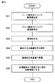
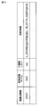
- FIG. 1 It is a figure which shows the board and the apparatus which concerns on embodiment. It is a figure which shows the structure of the apparatus included in FIG. It is a flowchart which shows the flow of the registration process of a diagnostic circuit model which is a pre-process. It is a figure which shows an example of a diagnostic circuit model. It is a flowchart which shows the flow of the registration process of the ID device list which is a pre-process. It is a figure which shows an example of the ID apparatus list. It is a flowchart which shows the flow of the troubleshooting process which is a pre-process. It is a figure which shows how the apparatus indirectly reads a device identification information using a scanner.
- FIG. 1 shows a board 200 and a device 100 according to the present embodiment that supports a state diagnosis of the board 200.
- the board 200 is a distribution board, a control board, a distribution board, and the like.
- the board 200 includes a front door 201.
- a plurality of board components 210 and 220 are arranged in the board 200.
- the board components 210 and 220 include a plurality of devices 210 and a line (wiring) 220 connecting the devices 210, as shown in FIG.
- FIG. 1 shows a state in which the front door 201 is closed. Therefore, in FIG. 1, the outline and the line 220 of the device 210, which cannot be visually recognized from the outside when the front door 210 is closed, are drawn by dotted lines.
- a board ID tag 202 is arranged on the surface of the front door 201.
- the board ID tag 202 has board identification information for identifying (identifying) the board 200.
- the board identification information is arbitrarily determined (set) by, for example, a user (maintenance person).
- a device ID tag 230 is arranged in each device 210.
- the device ID tag 230 has device identification information for identifying (identifying) the device 210.
- the device identification information is determined (set) by, for example, the manufacturer of the device 210, and the device ID tag 230 is attached to each device 210 by the manufacturer.
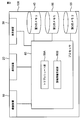
- FIG. 2 shows a schematic configuration of the device 100 according to the present embodiment.
- the device 100 is, for example, a mobile terminal.
- the user uses the device 100 when diagnosing the state of the board 200.
- the device 100 includes an image pickup device 10, a communication device 20, a display device 30, a first memory 40, a second memory 50, a third memory 55, and a processor 60.
- the image pickup device 10 is a camera or the like, and images a subject.
- the user uses the imaging device 10 to image, for example, the ID tags 202 and 230.
- the communication device 20 communicates with an external device (transmission and reception of data) wirelessly or by wire.
- the display device 30 displays various information.
- the display device 30 displays, for example, information on troubleshooting, diagnostic information described later, and the like.
- the second memory 50 stores the diagnostic circuit model M1.
- the third memory 55 stores a question flow chart that is used (provided to the user) when troubleshooting.
- the user identifies the cause of the trouble according to the question flowchart.
- the question flowchart is stylized in order to identify a trouble assumed in advance. That is, the question flowchart includes a systematically configured question and a plurality of cause identifications. The user can identify the cause by himself / herself by answering the questions prepared in advance in the question flowchart in order. That is, the user finds out the cause of the trouble that occurred in the board 200 based on the plurality of questions and the answers to the questions (based on the interactive question and answer) by troubleshooting using the question flowchart.
- the first memory 40 stores each data other than the diagnostic circuit model M1 and the question flowchart. For example, the first memory 40 accumulates troubleshooting results.
- the troubleshooting result at least indicates the specific content of the trouble identified by the troubleshooting performed on the board components 210 and 220 that caused the trouble.
- the board components 210 and 220 that caused the trouble are identified by the user performing troubleshooting on the board components 210 and 220 included in the board 200.
- the first memory 40 stores each program for executing various processes described later by the processor 60.
- Each of the memories 40, 50, 55 includes a RAM (Random Access Memory), a ROM (Read Only Memory), and the like. It should be noted that one storage device may have the functions of the memories 40, 50, 55, respectively.
- the processor 60 is communicably connected to the image pickup device 10, the communication device 20, the display device 30, the first memory 40, the second memory 50, and the third memory 55.
- the processor 60 reads each program and each data stored in the first memory 40. Further, the processor 60 controls each device 10, 20, 30, 40, 50, 55 according to the read program to execute a predetermined operation (function). Further, the processor 60 performs a predetermined calculation, analysis, processing, etc. in the processor 60 (each block 60A, 60B composed of the program) according to the read program. It should be noted that a part or all of each function executed by the processor 60 may be configured in hardware by one or a plurality of integrated circuits or the like.
- the processor 60 includes a troubleshooting unit 60A and a diagnostic information generation unit 60B as functional blocks.
- the operations of the blocks 60A and 60B will be described in detail in the description of the operations described later.
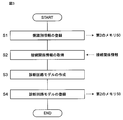
- step S1 the user registers the board identification information of the board 200 with respect to the second memory 50 of the device 100.
- the board identification information is the identification information possessed by the board ID tag 202 of the board 200.
- the connection relationship information is information indicating the connection relationship between the device 210 and the line 220 arranged on the board 200.
- the connection-related information CAD (Computer Aided Design) data having information on the device 210 in the panel 200 and information on the connection between the devices 210 (information on the line 220, etc.) can be adopted. ..
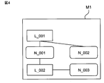
- FIG. 4 conceptually illustrates the diagnostic circuit model M1 created by the user.
- the diagnostic circuit model M1 connects the node identifier (first identifier) N_001, N_002, N_003, the line identifier (second identifier) L_001, L_002, the node identifier N_001, N_002, N_003, and the line identifier L_001, L_002. Represents a relationship.
- the node identifier N_001, N_002, N_003 is an identifier arbitrarily set by the user, and the node identifier N_001, N_002, N_003 specifies a predetermined device 210 arranged on the board 200. Further, the line identifiers L_001 and L_002 are identifiers arbitrarily set by the user, and the line identifiers L_001 and L_002 specify a predetermined line 220 arranged on the board 200.
- the connection-related information acquired in step S2 includes information on all devices 210 in the panel 200 and information on all lines 220 connected to the device 210.
- the diagnostic circuit model M1 does not need to have information on all the board components 210 and 220 arranged in the board 200. For example, the user selects a desired device 210 from the connection relationship information. Then, the diagnostic circuit model M1 may be created so as to include the information of the selected device 210 and the information of the line 220 connected to the selected device 210.
- the example of FIG. 4 shows that the user has selected three devices 210 arranged in the board 200 based on the connection relationship information. Then, in the example of FIG. 4, it is shown that the user has assigned the node identifiers N_001, N_002, and N_003 to each of the selected devices 210. Further, in the example of FIG. 4, it is shown that the user has assigned the line identifiers L_001 and L_002 to each line 220 connected to the selected device 210. Therefore, in the diagnostic circuit model M1 illustrated in FIG. 4, the information of the three devices 210 specified by the node identifiers N_001, N_002, N_003 and the information of the 220 of the two lines specified by the line identifiers L_001 and L_002 And include.
- the line 220 specified by the line identifier L_001 connects the device 210 specified by the node identifier N_001 and the device 210 specified by the node identifier N_002.
- the line 220 specified by the line identifier L_002 means that the device 210 specified by the node identifier N_001 and the device 210 specified by the node identifier N_003 are connected to each other.
- the user registers the diagnostic circuit model M1 in the second memory 50 of the device 100 in step S4.
- the second memory 50 stores the diagnostic circuit model M1 so that the diagnostic circuit model M1 created in step S3 is associated with the board identification information registered in step S1.
- the registration process of the diagnostic circuit model M1 shown in FIG. 3 is completed.
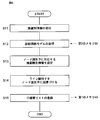
- step S11 the device 100 accepts the input of the board identification information.
- step S12 the processor 60 of the apparatus 100 reads (acquires) the diagnostic circuit model M1 (see FIG. 4) corresponding to the board identification information received in step S11 from the second memory 50.
- an ID device list L1 in which the "node identifier" and “line identifier” associated with each "device identification information" are arranged is generated.
- the generation process of the ID device list L1 will be described with reference to the ID device list L1 illustrated in FIG. As shown in FIG. 6, the ID device list L1 has "troubleshooting result" as an item in addition to "device identification information", "node identifier", and "line identifier".
- the user pays attention to each node identifier N_001, N_002, N_003 included in the diagnostic circuit model M1 (see FIG. 4) read in step S12. Then, the user sets the device identification information corresponding to each node identifier N_001, N_002, N_003 in the ID device list L1 for each node identifier N_001, N_002, N_003 (step S13).
- the device identification information is individual identification information set by the manufacturer of the device 210.
- the device identification information of the device 210 specified by the node identifier N_001 is "10001", and the device identification information of the device 210 specified by the node identifier N_002 is "10002", and the device identification information of the device 210 specified by the node identifier N_003 is. It is assumed that the device identification information of 210 is "1003". In this case, in the ID device list L1 shown in FIG. 6, the user associates the node identifier N_001 with the device identification information "10001", the node identifier N_002 with the device identification information "10002", and the node identifier N_003. , Associated with the device identification information "1003".
- the user pays attention to each line identifier L_001, L_002 included in the diagnostic circuit model M1 (see FIG. 4) read out in step S12.
- the line identifier L_001 is connected to the node identifier N_001 and the node identifier N_002.
- the line identifier L_002 is connected to the node identifier N_001 and the node identifier N_003. Therefore, in the ID device list L1 of FIG.
- the user associates the line identifier L_001 with the node identifier N_001 and the node identifier N_002, and associates the line identifier L_002 with the node identifier N_001 and so that the connection relationships are specified. It is associated with the node identifier N_003 (step S14).
- step S13 the node identifiers N_001, N_002, N_003 are associated with the device identification information "10001", “10002", "1003" in the ID device list L1
- step S14 the line identifier L_001, L_002 is associated with the node identifiers N_001, N_002, N_003.
- the process of step S14 can also be automatically executed by the processor 60 by using the connection information included in the diagnostic circuit model M1.
- step S14 the processor 60 associates the created ID device list L1 with the board identification information received in step S11 and registers (stores) it in the first memory 40 (step S15).
- the node identifier N_001, N_002, N_003 and / or the line identifier L_001, L_002 included in the diagnostic circuit model M1 is the device 210 (device identification information) arranged on the board 200. Is associated with.
- the ID device list L1 registered in step S15 as shown in FIG. 6, each information is written in the items of "device identification information", "node identifier", and "line identifier".
- the "Troubleshooting result" item is left blank. As a result, the registration process of the ID device list L1 shown in FIG. 5 is completed.
- the user performs troubleshooting by using the device 100.
- the user identifies the device 210 that is assumed to have the cause of the trouble.
- the device 100 reads the device identification information of the device 210 from the device ID tag 230 arranged in the specified device 210.
- the device 100 can directly read the device identification information.
- the device 100 may indirectly read the device identification information according to an embodiment as described later. That is, as shown in FIG. 8, the scanner 150 reads the device identification information of the device 210 from the device ID tag 230. Then, the scanner 150 wirelessly transmits the device identification information to the device 100. As a result, the device 100 can indirectly read the device identification information.
- FIG. 8 shows a state in which the front door 201 is open, and from the viewpoint of simplifying the drawing, the illustration of the front door 201 is omitted in FIG.
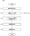
- step S22 of FIG. 7 the troubleshooting unit 60A of the processor 60 reads the question flowchart from the third memory 55. Specifically, the troubleshooting unit 60A reads the question flowchart associated with the device identification information read in step S21 from the third memory 55.
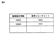
- FIG. 9 conceptually shows a plurality of question flowcharts stored in the third memory 55. As shown in FIG. 9, in the third memory 55, each question flowchart is associated (associated) with each device 210 (to each device identification information) arranged on the board 200.
- the question flowchart "XXX” is associated with the device identification information "10001"
- the question flowchart "YYY” is associated with the device identification information "10002”. Therefore, for example, if the device identification information read in step S21 is "10002", the troubleshooting unit 60A reads the question flowchart of "YYY" from the third memory 55.
- step S23 of FIG. 7 the troubleshooting unit 60A causes the display device 30 to display the question items and the like included in the question flowchart acquired in step S22. Then, the user performs troubleshooting by answering each question displayed on the display device 30 (step S23). Specifically, when the user answers each question included in the question flowchart, the user identifies the cause of the trouble (troubleshooting).
- each question included in the question flowchart is categorized according to the factor classification information.
- the factor classification information indicates whether the cause of the trouble is in the device 210 or other than the device 210 (for example, the environment surrounding the device 210).
- each factor classification information is specified by a factor classification identifier (third identifier) that is arbitrarily set.
- the question about "setting error” and “device life” is “question about device”. Therefore, these questions are classified as factor classification information indicating that the cause of the trouble is in the device 210.
- the factor classification information indicating that the cause of the trouble is in the device 210 is specified by the factor classification identifier FA.
- a question regarding "noise” and “temperature and humidity” is an "environmental question”. Therefore, these questions are classified as factor classification information indicating that the cause of the trouble is in the environment surrounding the device 210.
- the factor classification information indicating that the cause of the trouble is in the environment surrounding the device 210 is specified by the factor classification identifier FB.
- FIGS. 10 and 11 show examples of questions included in the question flowchart.
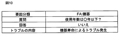
- the question is "Is the number of years of use less than or equal to ⁇ years?". And the question is about "equipment”. Therefore, this question is classified as factor classification information indicating that the cause of the trouble is in the device 210, and the factor classification information of the question is a factor classification identifier FA indicating that it is a "question about the device". Be identified.
- the answer to the question illustrated in FIG. 10 is "No"
- the device 100 indicates "Trouble occurrence due to device life” (see FIG. 10) as the content of the trouble (identification of the cause of the trouble). To that effect is provided to the user. That is, when the cause of the trouble is identified by the above question, the troubleshooting result includes the factor classification identifier FA and the content of the trouble (“problem occurrence due to device life”).
- the question is "Is the display of the device blinking?". And the question is about "environment”. Therefore, this question is classified as factor classification information indicating that the cause of the trouble is in the environment surrounding the device 210, and the factor classification information of the question is a factor classification indicating that it is an "environmental question”. Specified by the identifier FB. If the answer to the question illustrated in FIG. 11 is "Yes", the device 100 describes the content of the trouble (identification of the cause of the trouble) as "the possibility of trouble occurring due to noise" (see FIG. 11). It is provided to the user to that effect. That is, when the cause of the trouble is identified in the above question, the troubleshooting result includes the factor classification identifier FB and the content of the trouble (“possibility of trouble occurrence due to noise”).
- step S23 of FIG. 7 the troubleshooting result is obtained.
- the board components 210 and 220 that cause the trouble are identified, and the cause of the trouble is also identified.
- step S24 the troubleshooting unit 60A records the troubleshooting result in the first memory 40.
- the troubleshooting unit 60A reads the ID device list L1 having the device identification information read in step S21 from the first memory 40. Then, the troubleshooting unit 60A writes the obtained troubleshooting result in the "troubleshooting result" column of the ID device list L1.
- the troubleshooting unit 60A associates the obtained troubleshooting result with the device identification information read in step S21 in the ID device list L1. As a result, the troubleshooting process shown in FIG. 7 is completed.
- FIG. 12 shows an example of the ID device list L1 in which the troubleshooting result is written.
- the troubleshooting result included in the ID device list L1 at least indicates the content of the above trouble identified by the troubleshooting performed on the board 200. More specifically, each troubleshooting result includes the factor classification information (factor classification identifiers FA, FB) and a character string indicating the content of the trouble.
- troubleshooting has been carried out four times to obtain troubleshooting results.
- the first troubleshooting is performed on the device 210 specified by the device identification information "10001”, and the troubleshooting result is FA [abcd].
- the second troubleshooting is performed on the device 210 specified by the device identification information "10001”, and the troubleshooting result is FB [efgh].
- the third troubleshooting is performed on the device 210 specified by the device identification information "10002”, and the troubleshooting result is FA [abcd].
- the fourth troubleshooting is performed on the device 210 specified by the device identification information "10002", and the troubleshooting result is FB [efgh].
- the troubleshooting for obtaining the troubleshooting result has not been performed for the device 210 specified by the device identification information "1003".
- the above “1st”, “2nd”, “3rd”, and “4th” do not indicate the order in which the troubleshooting was performed, but are added merely for the purpose of clarifying the distinction. It was done.
- the diagnostic information generation unit 60B of the processor 60 aggregates the troubleshooting results (factor classification information and trouble contents) stored in the first memory 40, and causes a potential trouble in the board 200. Generate diagnostic information that represents the trend.
- the diagnostic information generation unit 60B diagnoses using the node identifiers N_001, N_002, N_003 and / or the line identifiers L_001 and L_002, which identify the board components 210 and 220 that caused the trouble. Represents information.
- the diagnostic information generation unit 60B includes the factor classification identifiers FA and FB indicating the factor classification information and the character string indicating the content of the trouble in the diagnosis information.
- the user identifies the board 200 to be the state diagnosis target.
- the device 100 reads the board identification information of the board 200 from the board ID tag 202 arranged on the specified board 200.
- the method of reading the board identification information is the same as the method of reading the device identification information described above (see the explanation of troubleshooting).
- step S32 the diagnostic information generation unit 60B of the processor 60 reads the ID device list L1 from the first memory 40.
- the ID device list L1 is associated (associated) with the board identification information read in step S31.
- the diagnostic information generation unit 60B has read the ID device list L1 illustrated in FIG. 12 in step S32.
- step S33 the diagnostic information generation unit 60B aggregates all the troubleshooting results included in the ID device list L1 (see FIG. 12) read in step S32. Through the aggregation process, the diagnostic information generation unit 60B generates diagnostic information indicating a potential trouble occurrence tendency in the board 200.
- FIG. 14 is a flowchart specifically showing a method of generating diagnostic information.
- the diagnostic information generation process will be described with reference to FIG.
- the diagnostic information generation unit 60B uses the ID device list L1 to perform a first logical product of the node identifier N_001, N_002, N_003 and the factor classification identifier FA, and the individual trouble identified by the troubleshooting. / Alternatively, it is represented as a second logical product of the line identifiers L_001 and L_002 and the factor classification identifier FB (see steps S41 and S42 in FIG. 14).
- the diagnostic information generation unit 60B generates a first logical product for each node identifier N_001, N_002, N_003 included in FIG. 12.
- the first logical product is the logical product of the node identifier N_001, N_002, N_003 and the troubleshooting result including the factor classification identifier FA corresponding to the node identifier N_001, N_002, N_003.
- the diagnostic information generation unit 60B generates "N_001 ⁇ FA" and "N_002 ⁇ FA" as the first logical product.
- step S42 the diagnostic information generation unit 60B generates a second logical product for each of the line identifiers L_001 and L_002 included in FIG. 12.
- the second logical product is the logical product of the line identifiers L_001 and L_002 and the troubleshooting result including the factor classification identifier FB corresponding to the line identifiers L_001 and L_002.
- the diagnostic information generation unit 60B generates "L_001 / FB", "L_002 / FB", and "L_001 / FB" as the second logical product.
- the diagnostic information generation unit 60B uses the ID device list L1 to perform a logical sum of the first logical product and the second logical product representing the trouble of the entire board 200. , Generate. That is, the diagnostic information generation unit 60B generates a logical sum of the first logical product generated in step S41 and the second logical product generated in step S42. For example, in the example of FIG. 12, the diagnostic information generation unit 60B generates (N_001 / FA) + (L_001 / FB) + (L_002 / FB) + (N_002 / FA) + (L_001 / FB).
- the common term is a term in which an identifier (node identifier, line identifier, factor classification identifier) is common in the plurality of logical products.
- the identifier included in the common term is referred to as a common identifier.
- step S44 the user selects the preferred common identifier through the operation on the device 100.
- the user can select the node identifier and the line identifier as the preferred common identifier.
- the user can select the factor classification identifier as the preferred common identifier.
- step S45 the diagnostic information generation unit 60B generates a logical expression by enclosing the common terms included in the above logical sum with a common identifier.
- the diagnostic information generation unit 60B arranges the above logical sums (by enclosing the common terms with a common identifier) according to the result selected in step S44, and generates a logical expression.
- step S44 it is assumed that the node identifier and the line identifier are selected as the preferred common identifier.
- the diagnostic information generation unit 60B encloses "L_001 / FB" and "L_001 / FB", which are ORed, with the line identifier L_001 which is a common identifier (common items related to the line identifier L_001).
- the OR is L_001 (FB + FB) + (N_001 / FA) + (L_002 / FB) + (N_002 / FA).
- the diagnostic information generation unit 60B determines whether or not there is another common term in the remaining logical product (N_001 / FA, L_002 / FB, N_002 / FA). Then, when another common term exists, the diagnostic information generation unit 60B sets the remaining term ⁇ (N_001 ⁇ FA) + (L_002 ⁇ FB) + (N_002 ⁇ FA) ⁇ of the logical sum to the other common term. Enclose with an identifier. As a result, the diagnostic information generation unit 60B generates L_001 (FB + FB) + (N_001 + N_002) FA + (L_002 ⁇ FB) as the first logical expression.
- step S44 it is assumed that the factor classification identifier is selected as the preferred common identifier.
- the diagnostic information generation unit 60B encloses "N_001 / FA" and "N_002 / FA" (common items related to the factor classification identifier FA) with the factor classification identifier FA, which is a common identifier, and "L_001 / FB".
- the diagnostic information generation unit 60B generates (N_001 + N_002) FA + (L_001 + L_002 + L_001) FB as the second logical expression.
- the node identifier and the line identifier are selected as the preferred common identifier, diagnostic information concentrated on the device 210 and the circuit (including the line 220) is provided. Therefore, it is effective in discovering potential risks in a narrow area.
- diagnostic information focused on the trouble phenomenon is provided. Therefore, it is effective in discovering potential risks over a wide area.
- step S46 the diagnostic information generation unit 60B generates diagnostic information based on the logical expression generated in step S46. Specifically, the diagnostic information generation unit 60B determines the terms (terms enclosed by the common identifier) arranged by the common identifier in the logical expression generated in step S45 as the diagnostic information.
- L_001 (FB + FB) and (N_001 + N_002) FA are determined as diagnostic information.
- L_001 (FB + FB) means that two troubles related to FB occurred in L_001.
- (N_001 + N_002) FA means that a trouble related to FA has occurred in N_001 and N_002.
- the diagnostic information generation unit 60B stores the diagnostic information determined in step S46 of FIG. 14 in step S34 of FIG. 13 in the first memory 40.
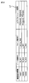
- the diagnostic information is recorded in the first memory 40 in a tabular format as illustrated in FIG.
- the board identification information, the diagnostic circuit model, the ID device list, and the diagnostic information are associated with each other.
- L_001 (FB + FB) and (N_001 + N_002) FA obtained from the first logical expression are stored in the first memory 40 as diagnostic information.
- the board identification information of the board 200, the diagnostic circuit model M1 of the board 200, the ID device list L1 of the board 200, and the diagnostic information for the board 200 are It is recorded in tabular form in association with each other.
- step S35 of FIG. 13 the display device (which can be grasped as an example of the output device) 30 displays (outputs) diagnostic information generated by the processor 60 and stored in the first memory 40.
- the device 100 may transmit (output) the diagnostic information generated by the processor 60 to an external device via a communication network or the like. As a result, the state diagnosis process for the board 200 shown in FIG. 13 is completed.
- the device 100 includes a first memory 40, a processor 60, and a display device 30 which is an example of an output device.
- the first memory 40 accumulates troubleshooting results.
- the troubleshooting result at least indicates the content of the trouble identified by the troubleshooting performed on the board components 210 and 220.
- the processor 60 aggregates the troubleshooting results and generates diagnostic information.
- the diagnostic information represents a trouble occurrence tendency latent in the board 200 having the board components 210 and 220.
- the display device 30 displays (outputs) the diagnostic information generated by the processor 60.
- the device 100 allows the user to take measures to prevent the board 200 from suddenly stopping.
- the board components 210 and 220 are the device 210 specified by the node identifier (first identifier) N_001, N_002, N_003 and the line identifier (second identifier) L_001. Includes line 220 specified by L_002.
- the device 100 includes a second memory 50 for storing the diagnostic circuit model M1.
- the diagnostic circuit model M1 is a connection between the node identifiers N_001 and N_002, N_003 and the line identifiers L_001 and L_002, which are created based on the connection relationship between the device 210 and the line 220 arranged on the board 200. Represents a relationship.
- the processor 60 generates an ID device list L1 in which "node identifiers" and "line identifiers” associated with each "device identification information" are arranged.
- the board components 210 and 220 are associated with the node identifiers N_001, N_002, N_003 and / or the line identifiers L_001 and L_002 included in the diagnostic circuit model M1.
- the processor 60 identifies the board components 210 and 220 that caused the trouble among the "node identifiers" and "line identifiers” listed in the ID device list L1, and the node identifiers N_001, N_002, N_003 and /.
- the line identifiers L_001 and L_002 are used to represent the above diagnostic information.
- the user can refer to the board components 210 and 220 that have caused the trouble by using the node identifiers N_001, N_002, N_003 and / or the line identifier. It can be grasped by L_001 and L_002.
- the troubleshooting result includes factor classification information and a character string indicating the content of the trouble.
- the factor classification information indicates whether the cause of the trouble is in the device 210 or in the environment surrounding the device 210.
- the processor 60 includes the factor classification identifiers FA and FB (third identifier) indicating the factor classification information and the character string indicating the content of the trouble in the diagnostic information.
- the processor 60 includes the factor classification identifiers FA and FB indicating the factor classification information and the character string indicating the content of the trouble in the diagnostic information. .. Therefore, it is possible to simplify the notation of the troubleshooting result.
- the processor 60 represents each trouble identified by troubleshooting as a first logical product or a second logical product.
- the first logical product is the logical product of the node identifiers N_001, N_002, N_003 and the factor classification identifier FA.
- the second logical product is the logical product of the line identifiers L_001 and L_002 and the factor classification identifier FB.
- the processor 60 expresses the trouble of the entire board 200 as the logical sum of the first logical product and the second logical product.
- the trouble of the entire board 200 can be represented by the above logical sum. Therefore, the diagnostic information can be easily organized.
- the processor 60 expresses the above-mentioned logical expression by enclosing the common terms including the common identifier in the terms of the plurality of logical products constituting the above logical sum with the common identifier. To generate. Then, the processor 60 generates the above-mentioned diagnostic information based on the logical expression.
- the above diagnostic information is formatted. Therefore, the diagnostic information can be easily and automatically created by the processor 60.
- a node identifier and a line identifier are selected as common identifiers.
- the types and times of troubles that have occurred in the device 210 and the line 220 in the past can be organized and provided as the above-mentioned diagnostic information.
- the factor classification identifier is selected as the common identifier. In this case, which device 210 and / or line 220 caused the same type of trouble in the past can be organized and provided as the above-mentioned diagnostic information.
- Display device 40 1st memory 50 2nd memory 55 3rd memory 60 Processor 60A Troubleshooting unit 60B Diagnostic information generation unit 100 Equipment 200 Board 210 Equipment 220 Line
Landscapes
- Physics & Mathematics (AREA)
- General Physics & Mathematics (AREA)
- Engineering & Computer Science (AREA)
- Automation & Control Theory (AREA)
- Testing And Monitoring For Control Systems (AREA)
- Test And Diagnosis Of Digital Computers (AREA)
Abstract
盤200の状態診断を支援する装置100は、第1のメモリ40、プロセッサ60、および表示装置30を、備える。第1のメモリ40は、盤構成要素210,22に対して実施されたトラブルシュートによって特定された、トラブルの内容を少なくとも示す、トラブルシュート結果を蓄積する。プロセッサ60は、トラブルシュート結果を集計して、盤200に潜在するトラブル発生傾向を表す診断情報を生成する。表示装置30は、プロセッサ60により生成された診断情報を出力する。
Description
この発明は、盤の状態診断を支援する装置、方法、およびプログラムに関し、たとえば、各種盤のユーザが盤の状態を診断するのを助けることが可能な、装置、方法、およびプログラムに関する。
各種盤、例えば制御盤のユーザ(主に、保守担当者)は、当該制御盤においてトラブル(問題)が発生したとき、対話型の質疑応答を行うアプリケーションソフトウェア(プログラム)を用いてトラブルシュートを実施して、トラブル原因の特定、およびトラブルの解決を図っている。トラブルシュートに関する技術は、たとえば、特許文献1(特開2018-119866号公報)に、記載されている。特許文献1には、トラブルシュートにより、機器等の異常を検出することなどが記載されている。
しかしながら、トラブルが発生したとき、単に事後的に、トラブルシュートを実施するだけでは、突発的に盤の使用が停止されることになる。そのような突発停止を防止するため、ユーザが、事前に、盤に潜在するトラブル発生傾向を把握することは、重要である。
そこで、この発明の課題は、ユーザが盤に潜在するトラブル発生傾向を把握するのを助ける、盤の状態診断を支援する装置、方法、およびプログラムを提供することにある。
上記課題を解決するため、この開示に係る装置は、
盤の状態診断を支援する装置であって、
上記盤は、複数の盤構成要素を含み、
上記装置は、
上記盤構成要素に対して実施されたトラブルシュートによって特定された、トラブルの内容を少なくとも示す、トラブルシュート結果を蓄積する、第1のメモリと、
上記トラブルシュート結果を集計して、上記盤に潜在するトラブル発生傾向を表す診断情報を生成する、プロセッサと、
上記プロセッサにより生成された上記診断情報を出力する、出力装置とを、備える、ことを特徴とする。
盤の状態診断を支援する装置であって、
上記盤は、複数の盤構成要素を含み、
上記装置は、
上記盤構成要素に対して実施されたトラブルシュートによって特定された、トラブルの内容を少なくとも示す、トラブルシュート結果を蓄積する、第1のメモリと、
上記トラブルシュート結果を集計して、上記盤に潜在するトラブル発生傾向を表す診断情報を生成する、プロセッサと、
上記プロセッサにより生成された上記診断情報を出力する、出力装置とを、備える、ことを特徴とする。
本明細書で、「盤」とは、配電盤、制御盤、分電盤などの各種盤を含む。「盤構成要素」とは、盤に配設された各種機器、それらの機器につながるライン(配線)などを含む。
「トラブルシュート」とは、複数の質問と当該質問に対する回答とに基づき(対話型の質疑応答に基づき)、盤において発生したトラブルの原因を突き止める、処理である。
この開示の装置では、第1のメモリは、上記トラブルシュートによって特定された、トラブルの内容を少なくとも示すトラブルシュート結果を、蓄積する。プロセッサは、上記トラブルシュート結果を集計して、上記盤に潜在するトラブル発生傾向を表す診断情報を生成する。そして、出力装置は、上記診断情報を出力する。したがって、ユーザが、出力装置に出力される診断情報を参照することにより、上記盤に潜在するトラブル発生傾向を把握することが、可能となる。よって、ユーザは、上記盤の突発停止を予防するための対策をとることができる。
一実施形態の装置では、
上記盤構成要素は、
第1の識別子で特定される機器と、
第2の識別子で特定され、上記機器に接続されるラインとを、含み、
上記盤に配設された、上記機器と上記ラインとの接続関係に基づいて作成される、上記第1の識別子と上記第2の識別子との接続関係を表す、診断回路モデルを格納する、第2のメモリを、さらに備え、
上記プロセッサは、
上記盤構成要素の各々に、上記診断回路モデルに含まれる、上記第1の識別子および/または上記第2の識別子を対応付けて、上記盤構成要素毎に対応付けられた第1の識別子および/または第2の識別子を並べてなるID機器リストを、生成し、
上記ID機器リストに挙げられた上記第1の識別子および/または上記第2の識別子のうち、トラブル原因となった上記盤構成要素を特定する、上記第1の識別子および/または上記第2の識別子を用いて、上記診断情報を表す、ことを特徴とする。
上記盤構成要素は、
第1の識別子で特定される機器と、
第2の識別子で特定され、上記機器に接続されるラインとを、含み、
上記盤に配設された、上記機器と上記ラインとの接続関係に基づいて作成される、上記第1の識別子と上記第2の識別子との接続関係を表す、診断回路モデルを格納する、第2のメモリを、さらに備え、
上記プロセッサは、
上記盤構成要素の各々に、上記診断回路モデルに含まれる、上記第1の識別子および/または上記第2の識別子を対応付けて、上記盤構成要素毎に対応付けられた第1の識別子および/または第2の識別子を並べてなるID機器リストを、生成し、
上記ID機器リストに挙げられた上記第1の識別子および/または上記第2の識別子のうち、トラブル原因となった上記盤構成要素を特定する、上記第1の識別子および/または上記第2の識別子を用いて、上記診断情報を表す、ことを特徴とする。
この一実施形態の装置では、上記第2のメモリは、上記盤に配設された、上記機器と上記ラインとの接続関係に基づいて、上記第1の識別子と上記第2の識別子との接続関係を表す、診断回路モデルを格納している。プロセッサは、上記盤構成要素の各々に、上記診断回路モデルに含まれる、上記第1の識別子および/または上記第2の識別子を対応付けて、上記盤構成要素毎に対応付けられた第1の識別子および/または第2の識別子を並べてなるID機器リストを生成し、さらに、上記ID機器リストに挙げられた上記第1の識別子および/または上記第2の識別子のうち、トラブル原因となった上記盤構成要素を特定する、上記第1の識別子および/または上記第2の識別子を用いて、上記診断情報を表す。したがって、ユーザは、診断情報を参照することにより、トラブル原因となった盤構成要素を、上記第1の識別子および/または上記第2の識別子によって把握できる。
一実施形態の装置では、
上記トラブルシュート結果は、
トラブルの発生要因が、上記機器にあるか又はその機器を取り巻く環境にあるかを示す、要因分類情報と、
上記トラブルの内容を示す文字列とを含み、
上記プロセッサは、上記診断情報に、
上記要因分類情報を示す第3の識別子と、
上記トラブルの内容を示す文字列とを、含める、ことを特徴とする。
上記トラブルシュート結果は、
トラブルの発生要因が、上記機器にあるか又はその機器を取り巻く環境にあるかを示す、要因分類情報と、
上記トラブルの内容を示す文字列とを含み、
上記プロセッサは、上記診断情報に、
上記要因分類情報を示す第3の識別子と、
上記トラブルの内容を示す文字列とを、含める、ことを特徴とする。
この一実施形態の装置では、上記プロセッサは、上記診断情報に、上記要因分類情報(トラブルの発生要因が上記機器にあるか又はその機器を取り巻く環境にあるかを示す)を示す第3の識別子と、上記トラブルの内容を示す文字列とを、含める。したがって、トラブルシュート結果の表記の簡素化を図ることができる。
一実施形態の装置では、
上記プロセッサは、
上記トラブルシュートによって特定された個々のトラブルを、上記第1の識別子と上記第3の識別子との第1の論理積、または、上記第2の識別子と上記第3の識別子との第2の論理積として表し、
上記盤全体についてのトラブルを、上記第1の論理積と上記第2の論理積との論理和として表す、ことを特徴とする。
上記プロセッサは、
上記トラブルシュートによって特定された個々のトラブルを、上記第1の識別子と上記第3の識別子との第1の論理積、または、上記第2の識別子と上記第3の識別子との第2の論理積として表し、
上記盤全体についてのトラブルを、上記第1の論理積と上記第2の論理積との論理和として表す、ことを特徴とする。
この一実施形態の装置では、上記プロセッサは、上記トラブルシュートによって特定された個々のトラブルを、上記第1の識別子と上記第3の識別子との第1の論理積、または、上記第2の識別子と上記第3の識別子との第2の論理積として表す。さらに、上記プロセッサは、上記盤全体についてのトラブルを、上記第1の論理積と上記第2の論理積との論理和として表す。これにより、上記盤全体についてのトラブルを、上記論理和により、表すことが可能となる。したがって、診断情報の整理が容易に行われ得る。
一実施形態の装置では、
上記プロセッサは、
上記論理和を構成する複数の論理積の項において、上記第1の識別子、上記第2の識別子、および上記第3の識別子のうち、共通の識別子を含む項を、当該共通の識別子で括ることにより、論理式を生成し、
上記論理式に基づき、上記診断情報を生成する、ことを特徴とする。
上記プロセッサは、
上記論理和を構成する複数の論理積の項において、上記第1の識別子、上記第2の識別子、および上記第3の識別子のうち、共通の識別子を含む項を、当該共通の識別子で括ることにより、論理式を生成し、
上記論理式に基づき、上記診断情報を生成する、ことを特徴とする。
この一実施形態の装置では、上記プロセッサは、上記論理和を構成する複数の論理積の項において、上記第1の識別子、上記第2の識別子、および上記第3の識別子のうち、共通の識別子を含む項を、当該共通の識別子で括ることにより、論理式を生成する。この論理式に基づき、上記診断情報が生成される。これにより、上記診断情報がフォーマット化される。したがって、上記診断情報は、上記プロセッサによって自動的に容易に作成され得る。
たとえば、第1の識別子を共通識別子として採用する場合には、機器で過去に発生したトラブルの種類、回数などを整理して、上記診断情報として、提供することができる。同様に、第2の識別子を共通識別子として採用する場合には、ラインで過去に発生したトラブルの種類、回数などを整理して、上記診断情報として、提供することができる。また、第3の識別子を共通識別子として採用する場合には、同じ種類のトラブルの発生原因が、どの機器および/またはラインで、過去に生じたのかを、整理して、上記診断情報として、提供することができる。
別の局面では、この開示の方法は、
盤の状態診断を支援する方法であって、
盤に含まれる盤構成要素に対して実施されたトラブルシュートによって特定された、トラブルの内容を少なくとも示す、トラブルシュート結果を、メモリに蓄積し、
上記トラブルシュート結果を集計して、上記盤に潜在するトラブル発生傾向を表す診断情報を生成し、
生成された上記診断情報を出力する、ことを特徴とする。
盤の状態診断を支援する方法であって、
盤に含まれる盤構成要素に対して実施されたトラブルシュートによって特定された、トラブルの内容を少なくとも示す、トラブルシュート結果を、メモリに蓄積し、
上記トラブルシュート結果を集計して、上記盤に潜在するトラブル発生傾向を表す診断情報を生成し、
生成された上記診断情報を出力する、ことを特徴とする。
この開示の方法では、上記トラブルシュートによって特定された、トラブルの内容を少なくとも示すトラブルシュート結果が、メモリに蓄積される。上記トラブルシュート結果を集計して、上記盤に潜在するトラブル発生傾向を表す診断情報が生成される。そして、生成された上記診断情報を出力する。したがって、ユーザが、出力される診断情報を参照することにより、上記盤に潜在するトラブル発生傾向を把握することが、可能となる。よって、ユーザは、上記盤の突発停止を予防するための対策をとることができる。
さらに別の局面では、この開示のプログラムは、上記方法を、コンピュータに実行させるためのプログラムである。
この開示のプログラムをコンピュータに実行させることによって、上記方法を実施することができる。
以上より明らかなように、この開示の、装置および方法によれば、盤に潜在する問題を把握することができ、結果として、盤の突発停止を予防することができる。また、この開示のプログラムをコンピュータに実行させることによって、上記方法を実施することができる。
以下、この発明の実施の形態を、図面を参照しながら詳細に説明する。
図1は、盤200と、当該盤200の状態診断を支援する、本実施の形態に係る装置100とを、示している。ここで、盤200は、配電盤、制御盤、および分電盤などである。盤200は、前扉201を備えている。また、盤200内には、複数の盤構成要素210,220が配設されている。ここで、盤構成要素210,220は、図1に示すように、複数の機器210と、機器210間を接続するライン(配線)220とを、含む。なお、図1は、前扉201が閉じた状態である。したがって、図1では、前扉210が閉じた状態で外部から視認できない、機器210の輪郭およびライン220は、点線にて描写している。
前扉201の面には、盤IDタグ202が配設される。当該盤IDタグ202は、盤200を識別(特定)するための盤識別情報を有する。ここで、盤識別情報は、たとえば、ユーザ(保守担当者)により、任意に決定(設定)される。
また、各機器210には、機器IDタグ230が配設される。当該機器IDタグ230は、機器210を識別(特定)するための機器識別情報を有する。ここで、機器識別情報は、たとえば、機器210の製造者により、決定(設定)され、当該製造者により、機器IDタグ230が、各機器210に取り付けられる。
図2は、本実施の形態に係る装置100の概略構成を示す。装置100は、たとえば携帯端末である。ユーザは、盤200の状態診断を行う際に、当該装置100を用いる。装置100は、撮像装置10、通信装置20、表示装置30、第1のメモリ40、第2のメモリ50、第3のメモリ55、およびプロセッサ60を、備える。
撮像装置10は、カメラ等であり、被写体を撮像する。ユーザは、撮像装置10を用いて、たとえば、各IDタグ202,230を撮像する。通信装置20は、無線または有線により、外部機器との通信(データの送受信)を行う。表示装置30は、各種情報を表示する。表示装置30は、たとえば、トラブルシュートに関する情報、後述する診断情報等を、表示する。
第2のメモリ50は、診断回路モデルM1を格納する。第3のメモリ55は、トラブルシュートを行う際に使用される(ユーザに提供される)、質問フローチャートを、格納する。盤200においてトラブルが生じると、ユーザは、当該質問フローチャートに沿って、トラブルの原因特定を行う。ここで、質問フローチャートは、あらかじめ想定されたトラブルを特定するために、定型化されたものである。つまり、質問フローチャートは、体系的に構成された、複数の質問と複数の原因特定とを含む。ユーザは、質問フローチャートにおいて予め用意された質問に順番に答えていくことで、自力で原因特定を行うことができる。つまり、ユーザは、質問フローチャートを用いたトラブルシュートにより、複数の質問と当該質問に対する回答とに基づき(対話型の質疑応答に基づき)、盤200において発生したトラブルの原因を突き止める。
第1のメモリ40は、診断回路モデルM1および質問フローチャート以外の、各データを格納する。たとえば、第1のメモリ40は、トラブルシュート結果を蓄積する。ここで、後述するように、トラブルシュート結果は、トラブルの原因となった盤構成要素210,220に対して実施されたトラブルシュートによって特定された、具体的なトラブルの内容を、少なくとも示す。ここで、トラブルの原因となった盤構成要素210,220は、ユーザが、盤200に含まれる盤構成要素210,220に対してトラブルシュートを実施することにより、特定される。また、第1のメモリ40は、後述する各種処理を、プロセッサ60で実行させるための各プログラムを、格納する。
各メモリ40,50,55は、RAM(Random Access Memory)およびROM(Read Only Memory)等を含む。なお、一つの記憶装置が、各メモリ40,50,55の機能を有していてもよい。
プロセッサ60は、撮像装置10、通信装置20、表示装置30、第1のメモリ40、第2のメモリ50、および第3のメモリ55と、通信可能に、接続されている。プロセッサ60は、第1のメモリ40に格納されている各プログラムおよび各データを読み込む。また、プロセッサ60は、読み込んだプログラムに従い、各装置10,20,30,40,50,55を制御し、所定の動作(機能)を実行させる。また、プロセッサ60は、読み込んだプログラムに従い、当該プロセッサ60内(プログラムによって構成される各ブロック60A,60B)において、所定の演算、解析、処理等を実施する。なお、プロセッサ60が実行する各機能の一部又は全部を、一つ或いは複数の集積回路等によりハードウェア的に構成してもよい。
図2に示すように、本実施の形態に係るプロセッサ60は、トラブルシュート部60Aおよび診断情報生成部60Bを、機能ブロックとして、備える。なお、各ブロック60A,60Bの動作は、後述する動作の説明において、詳述される。
次に、盤200の状態診断を支援する方法について、説明する。ここで、盤200の状態診断を行う前に、複数の前処理が実施される。そこで、以下では、まず、複数の前処理について説明し、その後、盤200に対する状態診断処理について、説明する。
(前処理:診断回路モデルM1の登録)
図3のフローチャートを用いて、前処理である、診断回路モデルM1の登録処理を説明する。
図3のフローチャートを用いて、前処理である、診断回路モデルM1の登録処理を説明する。
ステップS1において、ユーザは、装置100の第2のメモリ50に対して、盤200の盤識別情報を登録する。上記したように、当該盤識別情報は、盤200の盤IDタグ202が有する識別情報である。
次に、ステップS2において、ユーザは、盤200の接続関係情報を取得する。ここで、接続関係情報とは、盤200に配設された、機器210とライン220との接続関係を示す情報である。たとえば、当該接続関係情報は、盤200内の機器210の情報と、機器210間の接続に関する情報(ライン220の情報等)とを有する、CAD(Computer Aided Design )データを、採用することができる。
次に、ステップS3において、ユーザは、ステップS2で取得した接続関係情報に基づいて、診断回路モデルM1を作成する。図4は、ユーザにより作成される診断回路モデルM1を、概念的に例示している。診断回路モデルM1は、ノード識別子(第1の識別子)N_001,N_002,N_003と、ライン識別子(第2の識別子)L_001,L_002と、ノード識別子N_001,N_002,N_003とライン識別子L_001,L_002との接続関係とを、表す。
ノード識別子N_001,N_002,N_003は、ユーザにより任意に設定される識別子であり、当該ノード識別子N_001,N_002,N_003により、盤200に配設される所定の機器210が特定される。また、ライン識別子L_001,L_002は、ユーザにより任意に設定される識別子であり、当該ライン識別子L_001,L_002により、盤200に配設される所定のライン220が特定される。
ステップS2で取得される接続関係情報には、盤200内の全ての機器210の情報と、機器210と接続する全てのライン220の情報とが、含まれている。これに対して、診断回路モデルM1は、盤200内に配設される、全ての盤構成要素210,220の情報を有する必要はない。たとえば、ユーザは、上記接続関係情報から、所望の機器210を選択する。そして、選択した機器210の情報と、当該選択した機器210に接続されるライン220の情報とを含むように、診断回路モデルM1は作成されてもよい。
たとえば、図4の例は、ユーザが、接続関係情報を基に、盤200内に配設される3つの機器210を選択したことを示す。そして、図4の例では、当該選択した機器210の各々に、ユーザが、ノード識別子N_001,N_002,N_003を割り当てたことを示す。また、図4の例では、ユーザは、当該選択した機器210に接続される各ライン220に対して、ライン識別子L_001,L_002を割り当てたことを示す。よって、図4に例示する診断回路モデルM1は、ノード識別子N_001,N_002,N_003で特定される、3つの機器210の情報と、ライン識別子L_001,L_002で特定される、2つのラインの220の情報とを含む。
図4に例示する診断回路モデルM1は、ライン識別子L_001で特定されるライン220は、ノード識別子N_001で特定される機器210と、ノード識別子N_002で特定される機器210とを、接続していることを意味し、かつ、ライン識別子L_002で特定されるライン220は、ノード識別子N_001で特定される機器210と、ノード識別子N_003で特定される機器210とを、接続していることを意味する。
ステップS3において、診断回路モデルM1が作成されると、ステップS4において、ユーザは、当該診断回路モデルM1を、装置100の第2のメモリ50に登録する。ここで、ステップS3で作成された診断回路モデルM1が、ステップS1で登録された盤識別情報と関連付けられるように、第2のメモリ50は、当該診断回路モデルM1を格納する。以上により、図3に示した診断回路モデルM1の登録処理は、終了する。
(前処理:ID機器リストL1の登録)
図5のフローチャートを用いて、前処理である、ID機器リストL1の登録処理を説明する。
図5のフローチャートを用いて、前処理である、ID機器リストL1の登録処理を説明する。
ステップS11において、装置100は、盤識別情報の入力を受付ける。すると、ステップS12において、装置100のプロセッサ60は、第2のメモリ50から、ステップS11で受付けた盤識別情報に対応する、診断回路モデルM1(図4参照)を読み出す(取得する)。
次に、ステップS13,S14により、「機器識別情報」毎に対応付けられた「ノード識別子」、「ライン識別子」を並べてなるID機器リストL1が生成される。図6に例示するID機器リストL1を用いて、当該ID機器リストL1の生成処理を説明する。なお、図6に示すように、ID機器リストL1は、「機器識別情報」、「ノード識別子」、「ライン識別子」に加えて、「トラブルシュート結果」を、項目として、有する。
まず、ユーザは、ステップS12で読み出された診断回路モデルM1(図4参照)に含まれる、各ノード識別子N_001,N_002,N_003に注目する。そして、ユーザは、ID機器リストL1において、各ノード識別子N_001,N_002,N_003に対応する機器識別情報を、当該各ノード識別子N_001,N_002,N_003ごとに、設定する(ステップS13)。上記したように、機器識別情報は、機器210の製造元によって設定された個別の識別情報である。
ノード識別子N_001で特定される機器210の機器識別情報は、「10001」であり、ノード識別子N_002で特定される機器210の機器識別情報は、「10002」であり、ノード識別子N_003で特定される機器210の機器識別情報は、「10003」である、とする。この場合には、ユーザは、図6に示すID機器リストL1において、ノード識別子N_001を、機器識別情報「10001」に関連付け、ノード識別子N_002を、機器識別情報「10002」に関連付け、ノード識別子N_003を、機器識別情報「10003」に関連付ける。
次に、ユーザは、ステップS12で読み出した診断回路モデルM1(図4参照)に含まれる、各ライン識別子L_001,L_002に注目する。図4に例示する診断回路モデルM1では、ライン識別子L_001は、ノード識別子N_001およびノード識別子N_002と接続されている。また、ライン識別子L_002は、ノード識別子N_001およびノード識別子N_003と接続されている。そこで、図6のID機器リストL1において、当該各接続関係が特定されるように、ユーザは、ライン識別子L_001を、ノード識別子N_001およびノード識別子N_002に、関連付け、ライン識別子L_002を、ノード識別子N_001およびノード識別子N_003に、関連付ける(ステップS14)。
上記のように、ステップS13では、ID機器リストL1において、ノード識別子N_001,N_002,N_003が、機器識別情報「10001」,「10002」,「10003」と関連付けられ、ステップS14では、ライン識別子L_001,L_002が、ノード識別子N_001,N_002,N_003と関連付けられる。ここで、ステップS14の処理は、診断回路モデルM1に含まれる接続情報を用いて、プロセッサ60により、自動的に、実施することもできる。
ステップS14が終了すると、プロセッサ60は、作成されたID機器リストL1を、ステップS11で受付けた盤識別情報と関連付けて、第1のメモリ40に登録(格納)する(ステップS15)。
ここで、作成されたID機器リストL1では、診断回路モデルM1に含まれる、ノード識別子N_001,N_002,N_003および/またはライン識別子L_001,L_002は、盤200に配置される機器210(機器識別情報)に対応付けられている。なお、ステップS15で登録されるID機器リストL1では、図6に示すように、「機器識別情報」、「ノード識別子」、および「ライン識別子」の項目は、各情報が書き込まれているが、「トラブルシュート結果」の項目は、空欄のままである。以上により、図5に示したID機器リストL1の登録処理は、終了する。
(前処理:トラブルシュート実施)
次に、図7のフローチャートを用いて、前処理である、トラブルシュート処理を説明する。
次に、図7のフローチャートを用いて、前処理である、トラブルシュート処理を説明する。
盤200において、トラブルが発生したとする。そこで、トラブルを特定するため、ユーザは、装置100を用いて、トラブルシュートを実施する。まず、ユーザは、トラブル原因を有すると想定される機器210を、特定する。そして、ステップS21において、装置100は、特定した機器210に配設されている機器IDタグ230から、当該機器210の機器識別情報を読取る。
たとえば、装置100の撮像装置10を用いて、上記機器IDタグ230を、撮像することにより、装置100は、機器識別情報を、直接、読取ることができる。または、後述するような態様により、装置100は、間接的に、機器識別情報を読取ってもよい。つまり、図8に示すように、スキャナ150が、機器IDタグ230から、機器210の機器識別情報を読取る。そして、スキャナ150が当該機器識別情報を、装置100へ、無線で送信する。これにより、装置100は、間接的に、機器識別情報を読取ることができる。ここで、図8は、前扉201が開いた状態であり、図面簡略化の観点より、前扉201の図示は、図8では省略されている。
図7のステップS22において、プロセッサ60のトラブルシュート部60Aは、質問フローチャートを、第3のメモリ55から、読み出す。具体的に、トラブルシュート部60Aは、ステップS21で読取った機器識別情報と紐付けされている質問フローチャートを、第3のメモリ55から、読み出す。図9は、第3のメモリ55に格納されている、複数の質問フローチャートを、概念的に示している。図9に示すように、第3のメモリ55において、各質問フローチャートは、盤200に配設される各機器210に(各機器識別情報に)、紐付け(関連付け)されている。
図9の例では、質問フローチャート「XXX」は、機器識別情報「10001」と紐付けされており、質問フローチャート「YYY」は、機器識別情報「10002」と紐付けされている。よって、たとえば、ステップS21で読取った機器識別情報が、「10002」であれば、トラブルシュート部60Aは、第3のメモリ55から、「YYY」の質問フローチャートを読み出す。
次に、図7のステップS23において、トラブルシュート部60Aは、ステップS22で取得した質問フローチャートに含まれる質問事項等を、表示装置30に、表示させる。そして、ユーザは、表示装置30に表示された各質問に回答していくことにより、トラブルシュートを実施する(ステップS23)。具体的には、質問フローチャートに含まれる各質問に、ユーザが回答することにより、ユーザは、トラブル原因の特定を行う(トラブルシュート)。
ここで、質問フローチャートに含まれる各質問は、要因分類情報により、カテゴリ分けされている。要因分類情報は、トラブルの発生要因が、機器210にあるか、または当該機器210以外(たとえば、機器210を取り巻く環境)にあるかを、示す。また、各要因分類情報は、任意に設定される要因分類識別子(第3の識別子)によって、特定される。
たとえば、「設定ミス」および「機器寿命」等に関する質問は、「機器に関する質問」である。よって、これらの質問は、トラブルの発生要因が機器210にあることを示す要因分類情報として、分類される。なお、ここでは、トラブルの発生要因が機器210にあることを示す要因分類情報は、要因分類識別子FAにより、特定される。これに対して、たとえば、「ノイズ」および「温湿度」等に関する質問は、「環境に関する質問」である。よって、これらの質問は、トラブルの発生要因が機器210を取り巻く環境にあることを示す要因分類情報として、分類される。なお、ここでは、トラブルの発生要因が機器210を取り巻く環境にあることを示す要因分類情報は、要因分類識別子FBにより、特定される。
図10,11は、質問フローチャートに含まれる、質問の例を各々示す。図10の例では、質問は、「使用年数は、○年以下?」という内容である。そして、当該質問は、「機器」に関するものである。よって、この質問は、トラブルの発生要因が機器210にあることを示す要因分類情報として、分類され、当該質問の要因分類情報は、「機器に関する質問」であることを示す、要因分類識別子FAで特定される。なお、図10に例示した質問に対する回答が、「いいえ」である場合には、装置100は、トラブルの内容(トラブルの原因特定)として、「機器寿命によるトラブル発生」(図10参照)である旨を、ユーザに提供する。つまり、上記質問で、トラブル原因が特定される場合には、トラブルシュート結果は、要因分類識別子FAと、トラブルの内容(「機器寿命によるトラブル発生」)とを、含む。
図11の例では、質問は、「機器の表示が点滅している?」という内容である。そして、当該質問は、「環境」に関するものである。よって、この質問は、トラブルの発生要因が機器210を取り巻く環境にあることを示す要因分類情報として、分類され、当該質問の要因分類情報は、「環境に関する質問」であることを示す、要因分類識別子FBで特定される。なお、図11に例示した質問に対する回答が、「はい」である場合には、装置100は、トラブルの内容(トラブルの原因特定)として、「ノイズによるトラブル発生の可能性」(図11参照)である旨を、ユーザに提供する。つまり、上記質問で、トラブル原因が特定される場合には、トラブルシュート結果は、要因分類識別子FBと、トラブルの内容(「ノイズによるトラブル発生の可能性」)とを、含む。
さて、図7のステップS23でトラブルシュートが実施され、トラブルシュート結果が得られるとする。換言すると、トラブルの原因となる盤構成要素210,220が特定され、トラブルの原因も特定されたとする。すると、ステップS24において、トラブルシュート部60Aは、当該トラブルシュート結果を、第1のメモリ40に記録する。
具体的に、ステップS21で機器識別情報を読取り、当該機器識別情報により特定される機器210に対して、トラブルシュート結果が得られたとする(トラブル原因が特定されたとする)。この場合、まず、トラブルシュート部60Aは、第1のメモリ40から、ステップS21で読取った機器識別情報を有する、ID機器リストL1を読み出す。そして、トラブルシュート部60Aは、当該ID機器リストL1の「トラブルシュート結果」の欄に、得られたトラブルシュート結果を、書き込む。ここで、当該トラブルシュート結果の書き込みの際、トラブルシュート部60Aは、当該ID機器リストL1において、得られたトラブルシュート結果を、ステップS21で読取った機器識別情報と関連付ける。以上により、図7に示したトラブルシュート処理は、終了する。
図12は、トラブルシュート結果が書き込まれたID機器リストL1の一例を、示す。ID機器リストL1に含まれるトラブルシュート結果は、盤200に対して実施されたトラブルシュートによって特定された、上記トラブルの内容を少なくとも示す。より具体的に、各トラブルシュート結果は、上記要因分類情報(要因分類識別子FA,FB)と、上記トラブルの内容を示す文字列とを含む。
図12に例示するID機器リストL1おいて、機器識別情報「10001」「10002」に関して、合計4つのトラブルシュート結果(FA[abcd]、FB[efgh]、FA[abcd]、FB[efgh])が書き込まれている。ここで、「FA」および「FB」は、要因分類識別子を示しており、[abcd]および[efgh]は、トラブルの内容を示す文字列を、示している(たとえば、[abcd]は、「機器寿命によるトラブル発生」を示しており、[efgh]は、「ノイズによるトラブル発生の可能性」を意味している)。これに対して、ID機器リストL1おいて、機器識別情報「10003」に関しては、トラブルシュート結果が書き込まれていない。したがって、図12の例では、次のことが分かる。
つまり、過去において、トラブルシュート結果が得られるトラブルシュートが、4回実施されている。第1のトラブルシュートは、機器識別情報「10001」で特定される機器210に対して実施され、そのトラブルシュート結果は、FA[abcd]、である。第2のトラブルシュートは、機器識別情報「10001」で特定される機器210に対して実施され、そのトラブルシュート結果は、FB[efgh]、である。第3のトラブルシュートは、機器識別情報「10002」で特定される機器210に対して実施され、そのトラブルシュート結果は、FA[abcd]、である。第4のトラブルシュートは、機器識別情報「10002」で特定される機器210に対して実施され、そのトラブルシュート結果は、FB[efgh]、である。また、機器識別情報「10003」で特定される機器210に対しては、トラブルシュート結果が得られるトラブルシュートは、実施されていない。なお、上記「第1」、「第2」、「第3」、および「第4」は、トラブルシュートが実施された、順番を示しているものでなく、単に区別の明確化のために付されたものである。
(盤200に対する状態診断処理)
次に、上記各前処理の後に実施される、盤200に対する状態診断処理を、図13に示すフローチャートを用いて、説明する。当該状態診断処理では、プロセッサ60の診断情報生成部60Bは、第1のメモリ40に蓄積された上記トラブルシュート結果(要因分類情報およびトラブルの内容)を集計して、盤200に潜在するトラブル発生傾向を表す診断情報を生成する。
次に、上記各前処理の後に実施される、盤200に対する状態診断処理を、図13に示すフローチャートを用いて、説明する。当該状態診断処理では、プロセッサ60の診断情報生成部60Bは、第1のメモリ40に蓄積された上記トラブルシュート結果(要因分類情報およびトラブルの内容)を集計して、盤200に潜在するトラブル発生傾向を表す診断情報を生成する。
なお、後述から分かるように、診断情報生成部60Bは、トラブル原因となった盤構成要素210,220を特定する、ノード識別子N_001,N_002,N_003および/またはライン識別子L_001,L_002を用いて、診断情報を表す。診断情報生成部60Bは、当該診断情報に、要因分類情報を示す要因分類識別子FA,FBと、トラブルの内容を示す文字列とを、含める。
まず、ユーザは、状態診断対象となる盤200を、特定する。そして、ステップS31において、装置100は、特定した盤200に配設されている盤IDタグ202から、当該盤200の盤識別情報を読取る。なお、盤識別情報を読取る方法は、上述した、機器識別情報を読取る方法と(トラブルシュートの説明参照)、同様である。
次に、ステップS32において、プロセッサ60の診断情報生成部60Bは、第1のメモリ40から、ID機器リストL1を読出す。ここで、当該ID機器リストL1は、ステップS31で読取った盤識別情報と紐付け(関連付け)されているものである。ここで、診断情報生成部60Bは、ステップS32において、図12に例示したID機器リストL1を読み出したと、仮定する。
次に、ステップS33において、診断情報生成部60Bは、ステップS32で読出したID機器リストL1(図12参照)に含まれる、全てのトラブルシュート結果を集計する。当該集計処理により、診断情報生成部60Bは、盤200に潜在するトラブル発生傾向を表す診断情報を生成する。
図14は、診断情報を生成する方法を、具体的に示したフローチャートである。以下、図14を用いて、診断情報生成処理を、説明する。
まず、診断情報生成部60Bは、上記ID機器リストL1を用いて、トラブルシュートによって特定された個々のトラブルを、ノード識別子N_001,N_002,N_003と要因分類識別子FAとの第1の論理積、および/または、ライン識別子L_001,L_002と要因分類識別子FBとの第2の論理積として表す(図14のステップS41,S42参照)。
具体的に、ステップS41において、診断情報生成部60Bは、図12に含まれる各ノード識別子N_001,N_002,N_003について、第1の論理積を生成する。当該第1の論理積は、ノード識別子N_001,N_002,N_003と、当該ノード識別子N_001,N_002,N_003に対応する、要因分類識別子FAを含むトラブルシュート結果との、論理積である。ここで、図14の動作の説明では、説明簡略化のため、トラブルの内容を示す文字列は、記載を省略する。たとえば、図12の例では、診断情報生成部60Bは、第1の論理積として、「N_001・FA」および「N_002・FA」を、生成する。
次に、ステップS42において、診断情報生成部60Bは、図12に含まれる各ライン識別子L_001,L_002について、第2の論理積を生成する。当該第2の論理積は、ライン識別子L_001,L_002と、当該ライン識別子L_001,L_002に対応する、要因分類識別子FBを含むトラブルシュート結果との、論理積である。たとえば、図12の例では、診断情報生成部60Bは、第2の論理積として、「L_001・FB」、「L_002・FB」、および「L_001・FB」とを、生成する。
次に、ステップS43において、診断情報生成部60Bは、上記ID機器リストL1を用いて、盤200全体についてのトラブルを表す、上記第1の論理積と上記第2の論理積との論理和を、生成する。つまり、診断情報生成部60Bは、ステップS41で生成した第1の論理積と、ステップS42で生成した第2の論理積との、論理和を生成する。たとえば、図12の例では、診断情報生成部60Bは、(N_001・FA)+(L_001・FB)+(L_002・FB)+(N_002・FA)+(L_001・FB)を、生成する。
ここで、ステップS43で生成された論理和を構成する複数の論理積の項において、共通項が存在するとする。ここで、共通項とは、上記複数の論理積において、識別子(ノード識別子、ライン識別子、要因分類識別子)が共通する項である。なお、共通項に含まれる識別子を、共通識別子と称する。
ステップS44において、装置100に対する操作を通して、優先する共通識別子の選択を、ユーザが行う。ユーザは、ノード識別子およびライン識別子を、優先する共通識別子として選択できる。または、ユーザは、要因分類識別子を、優先する共通識別子として選択できる。
次に、ステップS45において、診断情報生成部60Bは、上記論理和に含まれる共通項を、共通識別子で括ることにより、論理式を生成する。ここで、診断情報生成部60Bは、ステップS44で選択された結果に応じて、上記論理和を整理し(共通項を共通識別子で括ることにより)、論理式を生成する。
たとえば、ステップS44において、ノード識別子およびライン識別子が、優先する共通識別子として選択されたとする。ここで、上記で例示した論理和には、ライン識別子L_001を含む項が、2つ存在する。そこで、まず、診断情報生成部60Bは、論理和構成する、「L_001・FB」および「L_001・FB」を(ライン識別子L_001に関する共通項を)、共通識別子であるライン識別子L_001で括る。その結果、上記論理和は、L_001(FB+FB)+(N_001・FA)+(L_002・FB)+(N_002・FA)、となる。次に、診断情報生成部60Bは、残りの論理積(N_001・FA、L_002・FB、N_002・FA)において、共通項が他に存在するか否かを判断する。そして、他に共通項が存在する場合には、診断情報生成部60Bは、論理和の残りの項{(N_001・FA)+(L_002・FB)+(N_002・FA)}を、他の共通識別子で括る。その結果は、診断情報生成部60Bは、第1の論理式として、L_001(FB+FB)+(N_001+N_002)FA+(L_002・FB)、を生成する。
他方、たとえば、ステップS44において、要因分類識別子が、優先する共通識別子として選択されたとする。ここで、上記で例示した論理和には、要因分類識別子FAを含む項が、2つ存在し、要因分類識別子FBを含む項が、3つ存在する。そこで、まず、診断情報生成部60Bは、「N_001・FA」および「N_002・FA」を(要因分類識別子FAに関する共通項を)、共通識別子である要因分類識別子FAで括り、「L_001・FB」、「L_002・FB」、および「L_001・FB」を(要因分類識別子FBに関する共通項を)、共通識別子である要因分類識別子FBで括る。その結果は、診断情報生成部60Bは、第2の論理式として、(N_001+N_002)FA+(L_001+L_002+L_001)FB、を生成する。
ここで、ノード識別子およびライン識別子が、優先する共通識別子として選択される場合には、機器210および回路(ライン220を含む)に集中した診断情報が提供される。したがって、狭域の潜在リスクの発見に有効である。他方、要因分類識別子が、優先する共通識別子として選択される場合には、トラブル現象に集中した診断情報が提供される。したがって、広域の潜在リスクの発見に有効である。
次に、ステップS46において、診断情報生成部60Bは、ステップS46で生成された論理式に基づき、診断情報を生成する。具体的に、診断情報生成部60Bは、ステップS45で生成された論理式において、共通識別子で整理できた項(共通識別子で括られた項)を、診断情報として、決定する。
上記第1の論理式では、L_001(FB+FB)および(N_001+N_002)FAが、診断情報として決定される。なお、L_001(FB+FB)は、L_001で、2件のFBに関するトラブルが発生したことを意味する。また、(N_001+N_002)FAは、N_001およびN_002で、FAに関するトラブルが発生したことを意味する。
他方、上記第2の論理式では、(N_001+N_002)FAおよび(L_001+L_002+L_001)FBが、診断情報として決定される。なお、FAに関するトラブルがN_001およびN_002で発生したことは、(N_001+N_002)FAによって表されている。また、FBに関するトラブルがL_001、L_002、およびL_001で発生したことは、(L_001+L_002+L_001)FBによって表されている。以上により、図14の処理(図13のステップS33)は、終了する。
次に、診断情報生成部60Bは、図13のステップS34において、図14のステップS46で決定した診断情報を、第1のメモリ40に、格納する。ここで、当該診断情報は、図15に例示するような、表形式で、第1のメモリ40に記録される。
図15の表形式では、盤識別情報、診断回路モデル、ID機器リスト、および診断情報が、関連付けされている。たとえば、図15の例では、上記第1の論理式から得られた、L_001(FB+FB)および(N_001+N_002)FAが、診断情報として、第1のメモリ40に格納されている。また、図15の例では、盤200の盤識別情報、盤200の診断回路モデルM1、盤200のID機器リストL1、および盤200に対する診断情報(L_001(FB+FB)および(N_001+N_002)FA)が、互いに関連づけて、表形式で記録されている。なお、上記において説明簡略化のために、トラブルの内容を示す文字列[abcd]および[efgh]の記載を省略していた。図15の例では、当該省略されていたトラブルの内容を示す文字列[abcd]および[efgh]が、明記されている。
次に、図13のステップS35において、表示装置(出力装置の一例と把握できる)30は、プロセッサ60により生成され、第1のメモリ40に格納される、診断情報を、表示(出力)する。
たとえば、図15に例示するように、L_001(FB[efgh]+FB[efgh])および(N_001+N_002)FA[abcd]が、診断情報として、生成される場合には、表示装置30は、次の診断情報を表示する。つまり、表示装置30は、L_001で特定されるライン220に関して、2件の「ノイズによるトラブル発生の可能性」(=[efgh])、およびN_001で特定される機器210とN_002で特定される機器210において、「機器寿命によるトラブル発生」(=[abcd])、という内容の診断情報を、表示する。
なお、装置100は、プロセッサ60により生成された診断情報を、通信網等を介して、外部装置へ、送信(出力)してもよい。以上により、図13に示す、盤200に対する状態診断処理は終了する。
以上のように、本実施の形態に係る装置100は、第1のメモリ40、プロセッサ60、および出力装置の一例である表示装置30を、備える。第1のメモリ40は、トラブルシュート結果を蓄積する。ここで、トラブルシュート結果は、盤構成要素210,220に対して実施されたトラブルシュートによって特定された、トラブルの内容を少なくとも示す。プロセッサ60は、上記トラブルシュート結果を集計して、診断情報を生成する。ここで、診断情報は、上記盤構成要素210,220を有する盤200に潜在する、トラブル発生傾向を表す。表示装置30は、プロセッサ60により生成された診断情報を表示(出力)する。
したがって、ユーザが、表示装置30に表示される診断情報を参照することにより、上記盤200に潜在するトラブル発生傾向を把握することが、可能となる。よって、本実施の形態に係る装置100により、ユーザは、盤200の突発停止を予防するための対策をとることができる。
また、本実施形態の装置100では、上記盤構成要素210,220は、ノード識別子(第1の識別子)N_001,N_002,N_003で特定される機器210と、ライン識別子(第2の識別子)L_001,L_002で特定されるライン220とを、含む。また、当該装置100は、診断回路モデルM1を格納する第2のメモリ50を、備える。ここで、診断回路モデルM1は、盤200に配設された、機器210とライン220との接続関係に基づいて作成される、ノード識別子N_001,N_002,N_003と、ライン識別子L_001,L_002との接続関係を表す。また、プロセッサ60は、「機器識別情報」毎に対応付けられた「ノード識別子」、「ライン識別子」を並べてなるID機器リストL1を生成する。ここで、ID機器リストL1において、盤構成要素210,220は、診断回路モデルM1に含まれる、ノード識別子N_001,N_002,N_003および/またはライン識別子L_001,L_002と、対応付けされる。そして、プロセッサ60は、ID機器リストL1に挙げられた「ノード識別子」、「ライン識別子」のうち、トラブル原因となった盤構成要素210,220を特定する、ノード識別子N_001,N_002,N_003および/またはライン識別子L_001,L_002を用いて、上記診断情報を表す。
したがって、ユーザは、本実施の形態に係る装置100により生成される診断情報を参照することにより、トラブル原因となった盤構成要素210,220を、ノード識別子N_001,N_002,N_003および/またはライン識別子L_001,L_002によって、把握することができる。
また、本実施形態に係る装置100では、上記トラブルシュート結果は、要因分類情報と、上記トラブルの内容を示す文字列とを、含む。要因分類情報は、トラブルの発生要因が、機器210にあるか、又はその機器210を取り巻く環境にあるか、を示す。また、プロセッサ60は、上記診断情報に、上記要因分類情報を示す要因分類識別子FA,FB(第3の識別子)と、上記トラブルの内容を示す文字列とを、含める。
上記のように、本実施の形態に係る装置100では、プロセッサ60は、上記診断情報に、上記要因分類情報を示す要因分類識別子FA,FBと、上記トラブルの内容を示す文字列とを、含める。したがって、トラブルシュート結果の表記の簡素化を図ることができる。
本実施の形態に係る装置100では、プロセッサ60は、トラブルシュートによって特定された個々のトラブルを、第1の論理積または第2の論理積として、表す。ここで、第1の論理積は、ノード識別子N_001,N_002,N_003と、要因分類識別子FAとの、論理積である。また、第2の論理積は、ライン識別子L_001,L_002と、要因分類識別子FBとの、論理積である。また、プロセッサ60は、盤200全体についてのトラブルを、上記第1の論理積と上記第2の論理積との論理和として表す。
したがって、本実施の形態に係る装置100では、盤200全体についてのトラブルを、上記論理和により、表すことが可能となる。したがって、診断情報の整理が容易に行われ得る。
また、本実施の形態に係る装置100では、プロセッサ60は、上記論理和を構成する複数の論理積の項において、共通識別子を含む共通項を、当該共通識別子で括ることにより、上述した論理式を生成する。そして、プロセッサ60は、当該論理式に基づき、上記診断情報を生成する。
したがって、本実施の形態に係る装置100では、上記診断情報がフォーマット化される。したがって、当該診断情報は、プロセッサ60によって、自動的に容易に、作成され得る。
たとえば、ノード識別子およびライン識別子が、共通識別子として、選択されたとする。この場合には、機器210およびライン220で過去に発生したトラブルの種類、回数などを整理して、上記診断情報として、提供することができる。他方、要因分類識別子が、共通識別子として、選択されたとする。この場合には、同じ種類のトラブルの発生原因が、どの機器210および/またはライン220で、過去に生じたのかを、整理して、上記診断情報として、提供することができる。
以上の実施の形態は例示であり、この発明の範囲から離れることなく様々な変形が可能である。上述した複数の実施の形態は、それぞれ単独で成立し得るものであるが、実施の形態同士の組みあわせも可能である。また、異なる実施の形態の中の種々の特徴も、それぞれ単独で成立し得るものであるが、異なる実施の形態の中の特徴同士の組みあわせも可能である。
30 表示装置
40 第1のメモリ
50 第2のメモリ
55 第3のメモリ
60 プロセッサ
60A トラブルシュート部
60B 診断情報生成部
100 装置
200 盤
210 機器
220 ライン
40 第1のメモリ
50 第2のメモリ
55 第3のメモリ
60 プロセッサ
60A トラブルシュート部
60B 診断情報生成部
100 装置
200 盤
210 機器
220 ライン
Claims (7)
- 盤の状態診断を支援する装置であって、
上記盤は、複数の盤構成要素を含み、
上記装置は、
上記盤構成要素に対して実施されたトラブルシュートによって特定された、トラブルの内容を少なくとも示す、トラブルシュート結果を蓄積する、第1のメモリと、
上記トラブルシュート結果を集計して、上記盤に潜在するトラブル発生傾向を表す診断情報を生成する、プロセッサと、
上記プロセッサにより生成された上記診断情報を出力する、出力装置とを、備える、
装置。 - 請求項1に記載の装置において、
上記盤構成要素は、
第1の識別子で特定される機器と、
第2の識別子で特定され、上記機器に接続されるラインとを、含み、
上記盤に配設された、上記機器と上記ラインとの接続関係に基づいて作成される、上記第1の識別子と上記第2の識別子との接続関係を表す、診断回路モデルを格納する、第2のメモリを、さらに備え、
上記プロセッサは、
上記盤構成要素の各々に、上記診断回路モデルに含まれる、上記第1の識別子および/または上記第2の識別子を対応付けて、上記盤構成要素毎に対応付けられた第1の識別子および/または第2の識別子を並べてなるID機器リストを、生成し、
上記ID機器リストに挙げられた上記第1の識別子および/または上記第2の識別子のうち、トラブル原因となった上記盤構成要素を特定する、上記第1の識別子および/または上記第2の識別子を用いて、上記診断情報を表す、
ことを特徴とする装置。 - 請求項2に記載の装置において、
上記トラブルシュート結果は、
トラブルの発生要因が、上記機器にあるか又はその機器を取り巻く環境にあるかを示す、要因分類情報と、
上記トラブルの内容を示す文字列とを含み、
上記プロセッサは、上記診断情報に、
上記要因分類情報を示す第3の識別子と、
上記トラブルの内容を示す文字列とを、含める、
ことを特徴とする装置。 - 請求項3に記載の装置において、
上記プロセッサは、
上記トラブルシュートによって特定された個々のトラブルを、上記第1の識別子と上記第3の識別子との第1の論理積、または、上記第2の識別子と上記第3の識別子との第2の論理積として表し、
上記盤全体についてのトラブルを、上記第1の論理積と上記第2の論理積との論理和として表す、
ことを特徴とする装置。 - 請求項4に記載の装置において、
上記プロセッサは、
上記論理和を構成する複数の論理積の項において、上記第1の識別子、上記第2の識別子、および上記第3の識別子のうち、共通の識別子を含む項を、当該共通の識別子で括ることにより、論理式を生成し、
上記論理式に基づき、上記診断情報を生成する、
ことを特徴とする装置。 - 盤の状態診断を支援する方法であって、
盤に含まれる盤構成要素に対して実施されたトラブルシュートによって特定された、トラブルの内容を少なくとも示す、トラブルシュート結果を、メモリに蓄積し、
上記トラブルシュート結果を集計して、上記盤に潜在するトラブル発生傾向を表す診断情報を生成し、
生成された上記診断情報を出力する、
ことを特徴とする方法。 - 請求項6に記載の方法を、コンピュータに実行させるためのプログラム。
Applications Claiming Priority (2)
| Application Number | Priority Date | Filing Date | Title |
|---|---|---|---|
| JP2019058379A JP7067515B2 (ja) | 2019-03-26 | 2019-03-26 | 盤の状態診断を支援する装置、方法、およびプログラム |
| JP2019-058379 | 2019-03-26 |
Publications (1)
| Publication Number | Publication Date |
|---|---|
| WO2020195495A1 true WO2020195495A1 (ja) | 2020-10-01 |
Family
ID=72609231
Family Applications (1)
| Application Number | Title | Priority Date | Filing Date |
|---|---|---|---|
| PCT/JP2020/007833 Ceased WO2020195495A1 (ja) | 2019-03-26 | 2020-02-26 | 盤の状態診断を支援する装置、方法、およびプログラム |
Country Status (2)
| Country | Link |
|---|---|
| JP (1) | JP7067515B2 (ja) |
| WO (1) | WO2020195495A1 (ja) |
Citations (3)
| Publication number | Priority date | Publication date | Assignee | Title |
|---|---|---|---|---|
| JP2009246688A (ja) * | 2008-03-31 | 2009-10-22 | Jfe Steel Corp | 制御盤内の監視装置および監視方法 |
| JP2012181859A (ja) * | 2012-05-07 | 2012-09-20 | Toshiba Mitsubishi-Electric Industrial System Corp | 遠隔監視装置 |
| JP2017010261A (ja) * | 2015-06-22 | 2017-01-12 | 株式会社東芝 | 受配電設備の保守用携帯端末、保守用プログラム、保守用サーバ |
-
2019
- 2019-03-26 JP JP2019058379A patent/JP7067515B2/ja active Active
-
2020
- 2020-02-26 WO PCT/JP2020/007833 patent/WO2020195495A1/ja not_active Ceased
Patent Citations (3)
| Publication number | Priority date | Publication date | Assignee | Title |
|---|---|---|---|---|
| JP2009246688A (ja) * | 2008-03-31 | 2009-10-22 | Jfe Steel Corp | 制御盤内の監視装置および監視方法 |
| JP2012181859A (ja) * | 2012-05-07 | 2012-09-20 | Toshiba Mitsubishi-Electric Industrial System Corp | 遠隔監視装置 |
| JP2017010261A (ja) * | 2015-06-22 | 2017-01-12 | 株式会社東芝 | 受配電設備の保守用携帯端末、保守用プログラム、保守用サーバ |
Also Published As
| Publication number | Publication date |
|---|---|
| JP7067515B2 (ja) | 2022-05-16 |
| JP2020160702A (ja) | 2020-10-01 |
Similar Documents
| Publication | Publication Date | Title |
|---|---|---|
| US7715037B2 (en) | Bi-directional remote visualization for supporting collaborative machine troubleshooting | |
| US8060418B2 (en) | Digital footprint driven multi-channel integrated support system | |
| US8660833B2 (en) | Method, computer program product and apparatus for providing an interactive network simulator | |
| US20180204383A1 (en) | Virtual reality maintenance and repair | |
| Asare et al. | Real-world prototyping and evaluation of digital twins for predictive facility maintenance | |
| JP2015087922A (ja) | 医療機器の修理情報管理装置とその動作方法及び制御プログラム、並びに修理情報管理システム | |
| CN102640157A (zh) | 医用图像诊断装置以及操作信息记录装置 | |
| CN109976725A (zh) | 一种基于轻量级流程引擎的流程程序开发方法及装置 | |
| US8001426B2 (en) | Electronic malfunction diagnostic apparatus and method | |
| CN106844296A (zh) | 一种通信方法和装置 | |
| JP7067515B2 (ja) | 盤の状態診断を支援する装置、方法、およびプログラム | |
| US7353230B2 (en) | Dynamic distributed customer issue analysis | |
| WO2021230190A1 (ja) | オペレーション支援装置、オペレーション支援方法、およびプログラム | |
| CN109753530A (zh) | 一种数据处理方法及其装置、介质、终端 | |
| CN115658500A (zh) | 一种混合开发中基于vue的前端错误日志上传方法及系统 | |
| CN112988267B (zh) | 加载方法、装置、存储介质及电子设备 | |
| JP3952066B2 (ja) | 情報処理装置、情報処理方法、プログラム、および、プログラムを記録したコンピュータ読み取り可能な記録媒体 | |
| JP6985767B1 (ja) | 診断装置、診断方法、診断システム、及びプログラム | |
| WO2014167733A1 (ja) | 制御システムの周辺装置および通信プロトコル異常箇所特定プログラム | |
| CN116153242B (zh) | 一种快速选择操作led显示屏的方法及led显示屏显示方法 | |
| JP7806479B2 (ja) | 仕様管理装置、及び通信システム | |
| JP2025037058A (ja) | 情報処理装置、情報処理方法、およびプログラム | |
| JP2007328676A (ja) | 電子機器の修理サービスシステム、及び修理サービス方法 | |
| JP2009526309A (ja) | 複数の製造業者の機器の保守を容易にする動的な情報の知識ベース | |
| JP7723650B2 (ja) | 情報処理装置、情報処理方法、及びプログラム |
Legal Events
| Date | Code | Title | Description |
|---|---|---|---|
| 121 | Ep: the epo has been informed by wipo that ep was designated in this application |
Ref document number: 20777315 Country of ref document: EP Kind code of ref document: A1 |
|
| NENP | Non-entry into the national phase |
Ref country code: DE |
|
| 122 | Ep: pct application non-entry in european phase |
Ref document number: 20777315 Country of ref document: EP Kind code of ref document: A1 |