WO2020195114A1 - 通信用装置、通信装置、通信方法、充電用装置、及びプログラム - Google Patents
通信用装置、通信装置、通信方法、充電用装置、及びプログラム Download PDFInfo
- Publication number
- WO2020195114A1 WO2020195114A1 PCT/JP2020/002936 JP2020002936W WO2020195114A1 WO 2020195114 A1 WO2020195114 A1 WO 2020195114A1 JP 2020002936 W JP2020002936 W JP 2020002936W WO 2020195114 A1 WO2020195114 A1 WO 2020195114A1
- Authority
- WO
- WIPO (PCT)
- Prior art keywords
- communication
- unit
- communication device
- port
- gimbal
- Prior art date
- Legal status (The legal status is an assumption and is not a legal conclusion. Google has not performed a legal analysis and makes no representation as to the accuracy of the status listed.)
- Ceased
Links
Images





Classifications
-
- H—ELECTRICITY
- H04—ELECTRIC COMMUNICATION TECHNIQUE
- H04B—TRANSMISSION
- H04B10/00—Transmission systems employing electromagnetic waves other than radio-waves, e.g. infrared, visible or ultraviolet light, or employing corpuscular radiation, e.g. quantum communication
- H04B10/11—Arrangements specific to free-space transmission, i.e. transmission through air or vacuum
- H04B10/114—Indoor or close-range type systems
- H04B10/116—Visible light communication
-
- H—ELECTRICITY
- H04—ELECTRIC COMMUNICATION TECHNIQUE
- H04B—TRANSMISSION
- H04B10/00—Transmission systems employing electromagnetic waves other than radio-waves, e.g. infrared, visible or ultraviolet light, or employing corpuscular radiation, e.g. quantum communication
- H04B10/11—Arrangements specific to free-space transmission, i.e. transmission through air or vacuum
- H04B10/112—Line-of-sight transmission over an extended range
-
- H—ELECTRICITY
- H04—ELECTRIC COMMUNICATION TECHNIQUE
- H04B—TRANSMISSION
- H04B10/00—Transmission systems employing electromagnetic waves other than radio-waves, e.g. infrared, visible or ultraviolet light, or employing corpuscular radiation, e.g. quantum communication
- H04B10/11—Arrangements specific to free-space transmission, i.e. transmission through air or vacuum
- H04B10/112—Line-of-sight transmission over an extended range
- H04B10/1121—One-way transmission
-
- H—ELECTRICITY
- H04—ELECTRIC COMMUNICATION TECHNIQUE
- H04B—TRANSMISSION
- H04B10/00—Transmission systems employing electromagnetic waves other than radio-waves, e.g. infrared, visible or ultraviolet light, or employing corpuscular radiation, e.g. quantum communication
- H04B10/11—Arrangements specific to free-space transmission, i.e. transmission through air or vacuum
- H04B10/112—Line-of-sight transmission over an extended range
- H04B10/1129—Arrangements for outdoor wireless networking of information
-
- H—ELECTRICITY
- H04—ELECTRIC COMMUNICATION TECHNIQUE
- H04B—TRANSMISSION
- H04B10/00—Transmission systems employing electromagnetic waves other than radio-waves, e.g. infrared, visible or ultraviolet light, or employing corpuscular radiation, e.g. quantum communication
- H04B10/40—Transceivers
-
- H—ELECTRICITY
- H04—ELECTRIC COMMUNICATION TECHNIQUE
- H04B—TRANSMISSION
- H04B10/00—Transmission systems employing electromagnetic waves other than radio-waves, e.g. infrared, visible or ultraviolet light, or employing corpuscular radiation, e.g. quantum communication
- H04B10/50—Transmitters
- H04B10/501—Structural aspects
- H04B10/502—LED transmitters
-
- H—ELECTRICITY
- H04—ELECTRIC COMMUNICATION TECHNIQUE
- H04B—TRANSMISSION
- H04B10/00—Transmission systems employing electromagnetic waves other than radio-waves, e.g. infrared, visible or ultraviolet light, or employing corpuscular radiation, e.g. quantum communication
- H04B10/80—Optical aspects relating to the use of optical transmission for specific applications, not provided for in groups H04B10/03 - H04B10/70, e.g. optical power feeding or optical transmission through water
- H04B10/806—Arrangements for feeding power
-
- H—ELECTRICITY
- H04—ELECTRIC COMMUNICATION TECHNIQUE
- H04W—WIRELESS COMMUNICATION NETWORKS
- H04W12/00—Security arrangements; Authentication; Protecting privacy or anonymity
- H04W12/06—Authentication
Definitions
- the present invention relates to a communication device, a communication device, a communication method, a charging device, and a program.
- Patent Document 1 Japanese Unexamined Patent Publication No. 2017-069803
- a communication device may include a gimbal and a communication unit rotatably supported by the gimbal and having a communication port for optical wireless communication and an imaging unit that captures the optical wireless communication direction of the communication port.
- the vector of the optical wireless communication direction of the communication port and the vector of the image pickup main direction by the image pickup unit may be the same.
- the gimbal may be a 3-axis gimbal.
- the communication device may include the communication device and a communication execution unit that executes optical wireless communication using the communication port.
- a program for causing the computer to function as the communication device is provided.
- a communication method executed by a communication device includes a gimbal, a communication unit rotatably supported by the gimbal, a communication port for optical wireless communication, and a communication unit having an imaging unit for imaging the optical wireless communication direction of the communication port, and optical wireless communication using the communication port.
- the communication execution unit may have a communication execution unit, and in the communication method, the optical axis of the communication port and the optical axis of the communication port of the communication device to be communicated match, based on the image captured by the imaging unit.
- a link establishment step for establishing an optical wireless communication link with the communication device to be communicated may be provided when it is determined that the communication has been performed.
- the communication method may include a rotation control step of controlling the rotation of the communication unit by the gimbal in order to maintain the coincidence of the optical axes based on the image captured by the imaging unit.
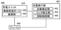
- a charging device may include a gimbal and a charging unit supported by the gimbal that has a wireless power receiving port and an imaging unit that captures an image in a direction opposite to the direction in which the wireless power receiving port receives power.
- the vector in the direction opposite to the direction in which the wireless power receiving port receives power may be the same as the vector in the main imaging direction by the imaging unit.
- a communication device may include a gimbal, an imaging unit supported by the gimbal, and a light emitting unit.
- the communication device may include an information transmission unit that transmits information by controlling light emission by the light emitting unit.
- the communication device may include an information acquisition unit that acquires information transmitted by the other communication device based on the light emitted by the light emitting unit included in the other communication device imaged by the image pickup unit.
- the light emitting unit may emit visible light.
- a program for causing the computer to function as the communication device is provided.
- a communication method executed by a communication device may include a gimbal, an imaging unit supported by the gimbal, and a light emitting unit, and the communication method may include an information transmission step of transmitting information by controlling light emission by the light emitting unit.
- the communication method may include an information acquisition step of acquiring information transmitted by another communication device based on light emitted by a light emitting unit included in the other communication device imaged by the imaging unit.
- An example of the communication device 100 is shown schematically. An example of using the communication device 100 is shown schematically. An example of using the communication device 100 is shown schematically. An example of using the communication device 100 is shown schematically. An example of using the communication device 100 is shown schematically. An example of the functional configuration of the communication device 200 is shown schematically. An example of the processing flow by the communication device 200 is shown schematically. An example of using the charging device 400 and the power feeding device 500 is schematically shown. An example of the functional configuration of the charging device 400 is schematically shown. An example of the functional configuration of the power feeding device 500 is schematically shown. An example of the hardware configuration of the computer 1200 that functions as the communication execution unit 210, the charging execution unit 450, or the power supply execution unit 550 is schematically shown.
- FIG. 1 schematically shows an example of a communication device 100.
- the communication device 100 includes a gimbal 140 and a communication unit 110 rotatably supported by the gimbal 140.
- the gimbal 140 is a gimbal having one or more axes.
- the gimbal 140 is, for example, a biaxial gimbal or a triaxial gimbal.
- the communication unit 110 has a communication port 120 for optical wireless communication.
- the communication port 120 may have a light emitting port 122 and a light receiving port 124.
- the type of light used for optical wireless communication by the communication unit 110 may be any type, and for example, light having a wavelength between infrared rays and visible light is used.
- LEDs Light Emitting Diodes
- LEDs Light Emitting Diodes
- infrared rays since the wavelength of infrared rays is longer than that of visible light, it is possible to reach a long distance with a small output. In addition, it is safe for the eyes and invisible to the naked eye, so it is possible to conceal communication.
- the communication unit 110 has an imaging unit 130.
- the imaging unit 130 images the optical wireless communication direction of the communication port 120.
- the image pickup unit 130 captures, for example, the light emission direction by the light emission port 122.
- the vector of the optical wireless communication direction of the communication port 120 and the vector of the image pickup main direction by the image pickup unit 130 may be the same.
- the image pickup main direction by the image pickup unit 130 is, for example, the direction of the optical axis of the lens included in the image pickup unit 130.
- Optical wireless communication has high directivity, and communication is not possible unless the optical axes of the communication ports of the communication targets match.
- the communication device 100 according to the present embodiment has a mechanism for automatically matching the optical axis of the communication port 120 with the optical axis of the communication port 120 of the communication device 100 included in the communication target.
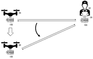
- FIG. 2 schematically shows a usage example of the communication device 100.
- the communication device 100 is attached to, for example, an unmanned aerial vehicle 20 such as a drone and a controller 30 for controlling the unmanned aerial vehicle 20.
- an unmanned aerial vehicle 20 such as a drone
- a controller 30 for controlling the unmanned aerial vehicle 20.
- the unmanned aerial vehicle 20 and the controller 30 track each other by, for example, analyzing the captured images captured by the respective imaging units 130 to recognize each other and continuously adjusting the angle of the communication port 120 by the gimbal 140. To do. Then, the unmanned aerial vehicle 20 and the controller 30 establish an optical wireless communication link when it is determined by the image captured by the imaging unit 130 that the optical axes of the communication ports 120 match each other.
- the establishment of the optical wireless communication link is performed, for example, before the unmanned aerial vehicle 20 starts flying.
- the operator 32 is moving the controller 30 so that the communication device 100 attached to the controller 30 and the communication device 100 of the unmanned aerial vehicle 20 arranged at an arbitrary location face each other, it is unmanned.
- the aircraft 20 and the controller 30 establish an optical wireless communication link according to the above-mentioned flow.
- another person may hold the unmanned aerial vehicle 20 and cooperate with the operator 32 so that the communication device 100 of the unmanned aerial vehicle 20 and the communication device 100 of the controller 30 face each other.
- the establishment of the optical wireless communication link may be performed after the unmanned aerial vehicle 20 starts flying.
- the operator 32 moves the controller 30 so that the unmanned aerial vehicle 20 has a function of autonomously flying, and the communication device 100 of the unmanned aerial vehicle 20 that is flying autonomously and the communication device 100 of the controller 30 face each other.
- the unmanned aerial vehicle 20 and the controller 30 establish an optical wireless communication link according to the above-mentioned flow.
- the unmanned aerial vehicle 20 and the controller 30 recognize each other's captured images captured by the respective imaging units 130, and adjust the angle of the communication port 120 by the gimbal 140.
- the tracking of each other is continued, and the optical axes of the communication ports 120 of each other are maintained in the same state.
- the unmanned aerial vehicle 20 freely moves in the three-dimensional space, the state in which the optical axes of the communication ports 120 are aligned can be maintained, and optical wireless communication can be continued.
- Radio waves make multipaths near devices that generate jamming radio waves, when a magnetic storm occurs, in ships, in tunnels, etc. Normal flight is hindered in an environment that causes it. It may be desired to enable the unmanned aerial vehicle 20 to fly even in such an environment, but according to the communication device 100 according to the present embodiment, it is possible to use optical wireless communication without depending on the radio wave environment. It is possible to control the unmanned aerial vehicle 20.
- the unmanned aerial vehicle 20 equipped with the communication device 100 while preventing the unmanned aerial vehicle 20 from being invaded by a third party by the jamming radio wave generator. it can. Further, for example, the unmanned aerial vehicle 20 can be safely flown even in a magnetic storm or in a multipath environment.
- FIG. 3 schematically shows a usage example of the communication device 100.
- the communication device 100 can be attached to any object.
- FIG. 3 illustrates a case where a communication device 100 is attached to each of the drone port 40, the vehicle 50, and the radio base station 62 in addition to the unmanned aerial vehicle 20 and the controller 30.
- the unmanned aerial vehicle 20 to which the communication device 100 is attached may execute optical wireless communication with the unmanned aerial vehicle 20, the controller 30, the drone port 40, the vehicle 50, and the radio base station 62 to which the communication device 100 is attached.
- the unmanned aerial vehicle 20 has, for example, an operation management system 70 that manages the operation of the unmanned aerial vehicle 20 on the network 60 via the wireless base station 62 by executing optical wireless communication with the wireless base station 62. Can communicate.
- the vehicles 50 to which the communication device 100 is attached may execute optical wireless communication.
- the objects to which the communication device 100 is attached may execute optical wireless communication.
- FIG. 4 schematically shows an example of an unmanned aerial vehicle 20 having a communication device 100 and a light emitting unit 300.
- the light emitting unit 300 outputs light having a directivity lower than the directivity of the light output from the light emitting port 122 of the communication port 120.
- the light output by the light emitting unit 300 may have a directivity lower than the directivity of the light output from the light emitting port 122 of the communication port 120, or may be omnidirectional.
- the light emitting unit 300 may output visible light.
- the light emitting unit 300 may output colorless light or may output colored light.
- the light emitting unit 300 may output light of a plurality of colors.
- a case where the light emitting unit 300 is an LED strobe light that outputs three colors of light will be described as an example.
- the unmanned aerial vehicle 20 may transmit information to another unmanned aerial vehicle 20 by controlling the light emission by the light emitting unit 300.
- Information transmission by light emission may be performed by any method. For example, a blinking signal that transmits information depending on the difference in light emission pattern is used.
- the unmanned aerial vehicle 20 may acquire the information transmitted by the other unmanned aerial vehicle 20 by controlling the light emission by the light emitting unit 300 by analyzing the light emission by the light emitting unit 300 imaged by the imaging unit 130.
- the unmanned aerial vehicle 20 executes communication by the light emitting unit 300 as a communication means until an optical wireless communication link is established with another unmanned aerial vehicle 20, for example.
- the first unmanned aerial vehicle 20 and the second unmanned aerial vehicle 20 transmit the authentication number by controlling the light emission by the light emitting unit 300 and can determine that the authentication is possible, the optical wireless communication link. Execute the establishment process of.
- the unmanned aerial vehicle 20 executes communication by the light emitting unit 300 as a communication means when communication is interrupted or communication is unstable due to an optical axis shift or too far away. You may. Further, the unmanned aerial vehicle 20 may communicate information related to optical wireless communication by the light emitting unit 300 after establishing an optical wireless communication link with another unmanned aerial vehicle 20. For example, the unmanned aerial vehicle 20 transmits an error correction signal corresponding to optical wireless communication by the light emitting unit 300.
- the use of communication by the light emitting unit 300 is not limited to these, and may be used for any purpose.
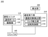
- FIG. 5 schematically shows an example of the functional configuration of the communication device 200.
- the communication device 200 may be an unmanned aerial vehicle 20, a controller 30, a drone port 40, a vehicle 50, a radio base station 62, or the like.
- the communication device 200 may be a device installed in each of the unmanned aerial vehicle 20, the controller 30, the drone port 40, the vehicle 50, and the radio base station 62.
- the communication device 200 includes a communication unit 110, a gimbal 140, a communication execution unit 210, and a light emitting unit 300.
- the communication execution unit 210 executes optical wireless communication using the communication unit 110.
- the communication execution unit 210 includes a communication target detection unit 212, a link establishment unit 214, and a rotation control unit 216.
- the communication target detection unit 212 detects the communication target communication device 200 based on the image captured by the imaging unit 130.
- the communication target detection unit 212 communicates with the other communication device 200, for example, when the light emitted by the light emitting unit 300 of the other communication device 200, which is imaged by the image pickup unit 130, satisfies a predetermined condition. It is detected as the target communication device 200.
- the predetermined condition is, for example, that the light emitted by the light emitting unit 300 of the other communication device 200 represents a preset authentication signal.
- the link establishment unit 214 establishes an optical wireless communication link with the communication device 200 to be communicated.
- the link establishment unit 214 determines that the optical axis of the communication unit 110 and the optical axis of the communication unit 110 of the communication device 200 to be communicated match, for example, based on the image captured by the image pickup unit 130, An optical communication wireless link is established with the communication device 200 to be communicated.
- the rotation control unit 216 communicates with the gimbal 140 in order to maintain the coincidence between the optical axis of the communication unit 110 and the optical axis of the communication unit 110 of the communication device 200 to be communicated. Controls the rotation of the unit 110.
- the rotation control unit 216 may rotate the communication unit 110 on the gimbal 140 according to the change in the relative positional relationship between the communication device 200 and the communication device 200 to be communicated.
- the communication execution unit 210 transmits information by controlling the light emission by the light emitting unit 300.
- the communication execution unit 210 transmits, for example, an authentication signal for performing authentication with another communication device 200 to the other communication device 200 by controlling the light emission by the light emitting unit 300.
- the communication execution unit 210 transmits information related to optical wireless communication using the communication unit 110 to the communication device 200 to be communicated by controlling the light emission by the light emitting unit 300.
- the communication execution unit 210 transmits, for example, an error correction signal corresponding to optical wireless communication using the communication unit 110 to the communication device 200 to be communicated by controlling the light emission by the light emitting unit 300.
- the communication device 200 includes all of the communication unit 110, the gimbal 140, the communication execution unit 210, and the light emitting unit 300.
- the communication device 200 may not include, for example, the light emitting unit 300.
- the communication device 200 does not have to include, for example, the communication port 120. That is, the communication device 200 does not have a function of executing optical wireless communication, and executes communication by the imaging unit 130 and the light emitting unit 300.
- the communication execution unit 210 transmits the authentication signal, the data signal, and the like by controlling the light emission by the light emitting unit 300.
- the communication execution unit 210 may be an example of an information transmission unit.
- the communication execution unit 210 captures the light emitting unit 300 included in the communication device 200 to be communicated by the imaging unit 130, and the communication device 200 to be communicated controls the light emission by the light emitting unit 300 to transmit the authentication signal. And acquire data signals and the like.
- the communication execution unit 210 may be an example of an information acquisition unit.
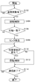
- FIG. 6 schematically shows an example of the processing flow by the communication device 200.
- the communication execution unit 210 continuously analyzes the image captured by the image pickup unit 130, and the communication device 200 and another communication device 200 establish an optical wireless communication link to obtain optical light.
- the flow of processing from communication via a wireless communication link to termination of communication is shown schematically.
- the communication execution unit 210 determines whether or not there is a communication device 200 to be communicated. When the communication target communication device 200 is detected by the communication target detection unit 212, the communication execution unit 210 determines that the communication target communication device 200 is present.
- the rotation control unit 216 controls the gimbal 140 to rotate the communication unit 110 based on the image captured by the image pickup unit 130.
- the link establishment unit 214 determines whether or not the optical axis of the communication unit 110 and the optical axis of the communication unit 110 of the communication device 200 to be communicated match, based on the image captured by the imaging unit 130. .. If it is determined that they match, the process proceeds to S108, and if it is determined that they do not match, the process returns to S104.
- the link establishment unit 214 establishes an optical wireless communication link with the communication device 200 to be communicated.
- the rotation control unit 216 determines whether or not the relative positional relationship between the communication device 200 and the communication device 200 to be communicated has changed. If it is determined that the change has occurred, the process proceeds to S112, and if it is determined that the change has not occurred, the process proceeds to S114.
- the rotation control unit 216 causes the gimbal 140 to rotate the communication unit 110 in order to maintain the alignment between the optical axis of the communication unit 110 and the optical axis of the communication unit 110 of the communication device 200 to be communicated. Control.
- S114 it is determined whether or not the communication between the communication device 200 and the communication device 200 to be communicated is completed. If it is determined that the process has ended, the process returns to S110, and if it is determined that communication has been completed, the process ends.
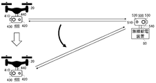
- FIG. 7 schematically shows a usage example of the charging device 400 and the power feeding device 500.
- the charging device 400 adds a wireless charging function to the attached device.
- FIG. 7 illustrates a case where the charging device 400 is attached to the unmanned aerial vehicle 20.
- the charging device 400 includes a gimbal 440 and a charging unit 410 rotatably supported by the gimbal 440.
- the gimbal 440 may be similar to the gimbal 140.
- the charging unit 410 has a wireless power receiving port 420 for wireless power reception and an imaging unit 430.
- the image pickup unit 430 takes an image in a direction opposite to the direction in which the wireless power receiving port 420 receives power.
- the vector in the direction opposite to the direction in which the wireless power receiving port 420 receives power may be the same as the vector in the image pickup main direction by the image pickup unit 430.
- the power supply device 500 is attached to the wireless power supply device 80 and has a function of supplying power to the charging device 400.
- the power feeding device 500 includes a gimbal 540 and a power feeding unit 510 rotatably supported by the gimbal 540.
- the gimbal 540 may be similar to the gimbal 140.
- the power supply unit 510 has a wireless power supply port 520 for wireless power supply and an imaging unit 530.
- the imaging unit 530 images, for example, the wireless power feeding direction by the wireless power feeding port 520.
- the vector of the wireless power feeding direction of the wireless power feeding port 520 and the vector of the imaging main direction by the imaging unit 430 may be the same.
- the unmanned aerial vehicle 20 and the wireless power feeding device 80 analyze the captured images captured by the imaging unit 430 and the imaging unit 530, respectively, and recognize each other.
- the unmanned aerial vehicle 20 continuously adjusts the angle of the charging unit 410 by the gimbal 440, and the wireless power supply device 80 tracks each other by continuously adjusting the angle of the power supply unit 510 by the gimbal 540.
- the unmanned aerial vehicle 20 and the wireless power feeding device 80 establish a charging link when it is determined from the captured image that the axes of the wireless power receiving port 420 and the wireless power feeding port 520 are aligned.
- the establishment of the charging link may be performed in the same manner as the establishment of the optical wireless communication link described with reference to FIG.
- the unmanned aerial vehicle 20 and the wireless power supply device 80 recognize each other by the captured image, and the angles of the charging unit 410 and the power supply unit 510 are adjusted to adjust the wireless power receiving port 420 and the wireless power supply port.
- the state in which the axis is aligned with 520 is maintained.
- FIG. 8 schematically shows an example of the functional configuration of the charging execution unit 450 that executes charging using the charging device 400.
- the charging execution unit 450 is arranged in a device to which the charging device 400 is attached.
- the charging execution unit 450 includes a target detection unit 452, a link establishment unit 454, and a rotation control unit 456.
- the target detection unit 452 detects a target for executing wireless power supply.
- the target detection unit 452 detects the target wireless power feeding device 80 based on the image captured by the image pickup unit 430.
- the target detection unit 452 may identify the wireless power feeding device 80 by analyzing the image captured by the image pickup unit 430. Further, for example, when the wireless power feeding device 80 has a light emitting unit similar to the light emitting unit 300, the light emitted by the light emitting unit of the wireless power feeding device 80 imaged by the imaging unit 430 satisfies a predetermined condition. In addition, the wireless power feeding device 80 is detected as a target.
- the link establishment unit 454 establishes a charging link with the target wireless power supply device 80.
- the link establishment unit 454 for example, based on the image captured by the image pickup unit 430, the axis of the wireless power receiving port 420 coincides with the axis of the wireless power supply port 520 included in the power supply device 500 attached to the wireless power supply device 80. If it is determined, a charging link is established.
- the charging execution unit 450 may charge the device to which the charging device 400 is attached by the electric power received through the charging link established by the link establishment unit 454.
- the rotation control unit 456 controls the rotation of the charging unit 410 by the gimbal 440 in order to maintain the alignment between the axis of the wireless power receiving port 420 and the axis of the wireless power feeding port 520 based on the image captured by the imaging unit 430.
- the rotation control unit 456 may rotate the charging unit 410 on the gimbal 440 according to the change in the relative positional relationship between the device to which the charging device 400 is attached and the wireless power feeding device 80.
- FIG. 9 schematically shows an example of the functional configuration of the power supply executing unit 550 that executes power supply using the power supply device 500.
- the power supply execution unit 550 is arranged in the wireless power supply device 80 to which the charging device 400 is attached.
- the power supply execution unit 550 includes a target detection unit 552, a link establishment unit 554, and a rotation control unit 556.
- the target detection unit 552 detects a target for executing wireless power supply.
- the target detection unit 552 detects the unmanned aerial vehicle 20 having the target charging device 400 based on the image captured by the image capturing unit 530.
- the target detection unit 552 may identify the unmanned aerial vehicle 20 by analyzing the image captured by the image pickup unit 530. Further, for example, when the unmanned aerial vehicle 20 has a light emitting unit 300, the light emitted by the light emitting unit 300 of the unmanned aerial vehicle 20 captured by the imaging unit 530 satisfies a predetermined condition. Is detected as a target.
- the link establishment unit 554 establishes a charging link with the target unmanned aerial vehicle 20. According to the link establishment unit 554, for example, based on the image captured by the image pickup unit 530, the axis of the wireless power supply port 520 and the axis of the wireless power receiving port 420 included in the charging device 400 attached to the unmanned aerial vehicle 20 are aligned. If determined, a charging link is established.
- the rotation control unit 556 controls the rotation of the power supply unit 510 by the gimbal 540 in order to maintain the alignment between the axis of the wireless power receiving port 420 and the axis of the wireless power feeding port 520 based on the image captured by the imaging unit 530.
- the rotation control unit 556 may rotate the power supply unit 510 on the gimbal 540 according to the change in the relative positional relationship between the unmanned aerial vehicle 20 to which the charging device 400 is attached and the wireless power supply device 80.
- FIG. 10 schematically shows an example of a hardware configuration of a computer 1200 that functions as a communication execution unit 210, a charging execution unit 450, or a power supply execution unit 550.
- a program installed on the computer 1200 causes the computer 1200 to function as one or more "parts" of the device according to the present embodiment, or causes the computer 1200 to perform an operation associated with the device according to the present embodiment or the one or more.
- a plurality of "parts" can be executed and / or a computer 1200 can be made to execute a process according to the present embodiment or a stage of the process.
- Such a program may be run by the CPU 1212 to cause the computer 1200 to perform certain operations associated with some or all of the blocks of the flowcharts and block diagrams described herein.
- the computer 1200 includes a CPU 1212, a RAM 1214, and a graphic controller 1216, which are connected to each other by a host controller 1210.
- the computer 1200 also includes an input / output unit such as a communication interface 1222, a storage device 1224, and an IC card drive, which are connected to the host controller 1210 via an input / output controller 1220.
- the storage device 1224 may be a hard disk drive, a solid state drive, or the like.
- the computer 1200 also includes a legacy I / O unit such as a ROM 1230 and a keyboard, which are connected to the I / O controller 1220 via an I / O chip 1240.
- the CPU 1212 operates according to the programs stored in the ROM 1230 and the RAM 1214, thereby controlling each unit.
- the graphic controller 1216 acquires the image data generated by the CPU 1212 in a frame buffer or the like provided in the RAM 1214 or itself so that the image data is displayed on the display device 1218.
- the communication interface 1222 communicates with other electronic devices via the network.
- the storage device 1224 stores programs and data used by the CPU 1212 in the computer 1200.
- the IC card drive reads the program and data from the IC card and / or writes the program and data to the IC card.
- the ROM 1230 stores in it a boot program or the like executed by the computer 1200 at the time of activation, and / or a program depending on the hardware of the computer 1200.
- the input / output chip 1240 may also connect various input / output units to the input / output controller 1220 via a USB port, a parallel port, a serial port, a keyboard port, a mouse port, and the like.
- the program is provided by a computer-readable storage medium such as an IC card.
- the program is read from a computer-readable storage medium, installed in a storage device 1224, RAM 1214, or ROM 1230, which is also an example of a computer-readable storage medium, and executed by the CPU 1212.
- the information processing described in these programs is read by the computer 1200 and provides a link between the program and the various types of hardware resources described above.
- the device or method may be configured to implement the operation or processing of information in accordance with the use of computer 1200.
- the CPU 1212 executes a communication program loaded in the RAM 1214, and performs communication processing on the communication interface 1222 based on the processing described in the communication program. You may order.
- the communication interface 1222 reads the transmission data stored in the transmission buffer area provided in the recording medium such as the RAM 1214, the storage device 1224, or the IC card, and sends the read transmission data to the network.
- the received data transmitted or received from the network is written in the reception buffer area or the like provided on the recording medium.
- the CPU 1212 allows the RAM 1214 to read all or necessary parts of a file or database stored in an external recording medium such as a storage device 1224 or an IC card, and performs various types of processing on the data on the RAM 1214. May be executed. The CPU 1212 may then write back the processed data to an external recording medium.
- an external recording medium such as a storage device 1224 or an IC card
- the CPU 1212 describes various types of operations, information processing, conditional judgment, conditional branching, unconditional branching, and information retrieval described in various parts of the present disclosure with respect to the data read from the RAM 1214, and is specified by the instruction sequence of the program. Various types of processing may be performed, including / replacement, etc., and the results are written back to the RAM 1214. Further, the CPU 1212 may search for information in a file, a database, or the like in the recording medium.
- the CPU 1212 is the first of the plurality of entries.
- the attribute value of the attribute of is searched for the entry that matches the specified condition, the attribute value of the second attribute stored in the entry is read, and the first attribute satisfying the predetermined condition is selected. You may get the attribute value of the associated second attribute.
- the program or software module described above may be stored on a computer 1200 or in a computer-readable storage medium near the computer 1200.
- a recording medium such as a hard disk or RAM provided in a dedicated communication network or a server system connected to the Internet can be used as a computer-readable storage medium, whereby the program can be transferred to the computer 1200 via the network.
- the block in the flowchart and the block diagram in the present embodiment may represent a stage of the process in which the operation is executed or a "part" of the device having a role of executing the operation.
- Specific stages and "parts" are supplied with dedicated circuits, programmable circuits supplied with computer-readable instructions stored on computer-readable storage media, and / or computer-readable instructions stored on computer-readable storage media. It may be implemented by the processor.
- Dedicated circuits may include digital and / or analog hardware circuits, and may include integrated circuits (ICs) and / or discrete circuits.
- Programmable circuits include logical products, logical sums, exclusive logical sums, negative logical products, negative logical sums, and other logical operations, such as, for example, field programmable gate arrays (FPGAs), programmable logic arrays (PLAs), and the like. , Flip-flops, registers, and reconfigurable hardware circuits, including memory elements.
- the computer-readable storage medium may include any tangible device capable of storing instructions executed by the appropriate device, so that the computer-readable storage medium having the instructions stored therein is in a flow chart or block diagram. It will include a product that contains instructions that can be executed to create means for performing the specified operation.
- Examples of computer-readable storage media may include electronic storage media, magnetic storage media, optical storage media, electromagnetic storage media, semiconductor storage media, and the like. More specific examples of computer-readable storage media include floppy (registered trademark) disks, diskettes, hard disks, random access memory (RAM), read-only memory (ROM), and erasable programmable read-only memory (EPROM or flash memory).
- EEPROM Electrically Erasable Programmable Read Only Memory
- SRAM Static Random Access Memory
- CD-ROM Compact Disc Read Only Memory
- DVD Digital Versatile Disc
- Blu-ray® Disc Memory Stick
- Integrated circuit cards and the like may be included.
- Computer-readable instructions are assembler instructions, instruction set architecture (ISA) instructions, machine instructions, machine-dependent instructions, microcode, firmware instructions, state-setting data, or object-oriented programming such as Smalltalk, JAVA®, C ++, etc. Includes either source code or object code written in any combination of one or more programming languages, including languages and traditional procedural programming languages such as the "C" programming language or similar programming languages. Good.
- Computer-readable instructions are used to generate means for a general-purpose computer, a special-purpose computer, or the processor of another programmable data processing device, or a programmable circuit, to perform an operation specified in a flowchart or block diagram.
Landscapes
- Engineering & Computer Science (AREA)
- Computer Networks & Wireless Communication (AREA)
- Signal Processing (AREA)
- Physics & Mathematics (AREA)
- Electromagnetism (AREA)
- Computer Security & Cryptography (AREA)
- Computing Systems (AREA)
- Optical Communication System (AREA)
- Charge And Discharge Circuits For Batteries Or The Like (AREA)
Abstract
Description
[先行技術文献]
[特許文献]
[特許文献1]特開2017-069803号公報
Claims (18)
- ジンバルと、
前記ジンバルによって回転可能に支持された、光無線通信用の通信ポート及び前記通信ポートの光無線通信方向を撮像する撮像部を有する通信ユニットと
を備える通信用装置。 - 前記通信ポートの光無線通信方向のベクトルと、前記撮像部による撮像主方向のベクトルとが同一である、請求項1に記載の通信用装置。
- 請求項1又は2に記載の通信用装置と、
前記通信ポートを用いた光無線通信を実行する通信実行部と
を備える通信装置。 - 前記通信実行部は、
前記撮像部による撮像画像に基づいて、前記通信ポートの光軸と、通信対象の通信装置が有する通信ポートの光軸とが一致したと判定した場合に、前記通信対象の前記通信装置との間で光無線通信リンクを確立するリンク確立部と、
前記撮像部による撮像画像に基づいて、前記光軸の一致を維持すべく、前記ジンバルによる前記通信ユニットの回転を制御する回転制御部と
を有する、請求項3に記載の通信装置。 - 前記撮像部による撮像画像に基づいて、通信対象の通信装置を検出する通信対象検出部
を備え、
前記リンク確立部は、前記通信対象検出部によって検出された前記通信対象の通信装置との間で前記光無線通信リンクを確立する、請求項4に記載の通信装置。 - 前記通信対象検出部は、前記撮像部によって撮像された、他の通信装置が有する発光部による発光が、予め定められた条件を満たした場合に、前記他の通信装置を前記通信対象の通信装置として検出する、請求項5に記載の通信装置。
- 前記他の通信装置が有する発光部は、可視光を発光する、請求項6に記載の通信装置。
- 前記通信ポートから出力される光の指向性よりも指向性が低い光を出力する発光部
を備え、
前記通信実行部は、前記発光部による発光を制御することによって情報を送信する、請求項4から7のいずれか一項に記載の通信装置。 - 前記通信実行部は、前記発光部による発光を制御することによって、他の通信装置との間で認証を行うための認証信号を送信する、請求項8に記載の通信装置。
- 前記通信実行部は、前記発光部による発光を制御することによって、前記通信ポートを用いた光無線通信に関連する情報を送信する、請求項8又は9に記載の通信装置。
- 前記通信実行部は、前記発光部による発光を制御することによって、前記通信ポートを用いた光無線通信に対応するエラー訂正信号を送信する、請求項10に記載の通信装置。
- コンピュータを、請求項4から11のいずれか一項に記載の通信装置として機能させるためのプログラム。
- 通信装置によって実行される通信方法であって、
前記通信装置は、ジンバル、前記ジンバルによって回転可能に支持された、光無線通信用の通信ポート及び前記通信ポートの光無線通信方向を撮像する撮像部を有する通信ユニット、及び前記通信ポートを用いた光無線通信を実行する通信実行部を有し、
前記撮像部による撮像画像に基づいて、前記通信ポートの光軸と、通信対象の通信装置が有する通信ポートの光軸とが一致したと判定した場合に、前記通信対象の前記通信装置との間で光無線通信リンクを確立するリンク確立段階と、
前記撮像部による撮像画像に基づいて、前記光軸の一致を維持すべく、前記ジンバルによる前記通信ユニットの回転を制御する回転制御段階と
を備える通信方法。 - ジンバルと、
前記ジンバルによって支持された、無線受電ポート及び前記無線受電ポートが受電する方向と反対の方向を撮像する撮像部を有する充電ユニットと
を備える充電用装置。 - 前記無線受電ポートが受電する方向と反対の方向のベクトルと、前記撮像部による撮像主方向のベクトルとが同一である、請求項14に記載の充電用装置。
- 通信装置であって、
ジンバルと、
前記ジンバルによって支持された撮像部と、
発光部と、
前記発光部による発光を制御することによって情報を送信する情報送信部と、
前記撮像部によって撮像された他の通信装置が備える発光部による発光に基づいて、前記他の通信装置によって送信された情報を取得する情報取得部と
を備える通信装置。 - コンピュータを、請求項16に記載の通信装置として機能させるためのプログラム。
- 通信装置によって実行される通信方法であって、
前記通信装置は、ジンバル、前記ジンバルによって支持された撮像部、及び発光部を有し、
前記発光部による発光を制御することによって情報を送信する情報送信段階と、
前記撮像部によって撮像された他の通信装置が備える発光部による発光に基づいて、前記他の通信装置によって送信された情報を取得する情報取得段階と
を備える通信方法。
Priority Applications (5)
| Application Number | Priority Date | Filing Date | Title |
|---|---|---|---|
| CN202080023948.2A CN113632388B (zh) | 2019-03-26 | 2020-01-28 | 通信用装置、通信装置、通信方法、充电用装置以及程序 |
| IL286507A IL286507B2 (en) | 2019-03-26 | 2020-01-28 | Device for communication, communication device, communication method, charging device and program |
| KR1020217030172A KR102525500B1 (ko) | 2019-03-26 | 2020-01-28 | 통신용 장치, 통신 장치, 통신 방법, 충전용 장치, 및 프로그램 |
| GB2115012.3A GB2596972B (en) | 2019-03-26 | 2020-01-28 | Device for communication, communication device, communication method, device for charging, and program |
| US17/483,856 US11870494B2 (en) | 2019-03-26 | 2021-09-24 | Device for communication, communication device, communication method, device for charging, and computer readable storage medium |
Applications Claiming Priority (2)
| Application Number | Priority Date | Filing Date | Title |
|---|---|---|---|
| JP2019-058084 | 2019-03-26 | ||
| JP2019058084A JP6821733B2 (ja) | 2019-03-26 | 2019-03-26 | 通信装置、通信方法、及びプログラム |
Related Child Applications (1)
| Application Number | Title | Priority Date | Filing Date |
|---|---|---|---|
| US17/483,856 Continuation US11870494B2 (en) | 2019-03-26 | 2021-09-24 | Device for communication, communication device, communication method, device for charging, and computer readable storage medium |
Publications (1)
| Publication Number | Publication Date |
|---|---|
| WO2020195114A1 true WO2020195114A1 (ja) | 2020-10-01 |
Family
ID=72610049
Family Applications (1)
| Application Number | Title | Priority Date | Filing Date |
|---|---|---|---|
| PCT/JP2020/002936 Ceased WO2020195114A1 (ja) | 2019-03-26 | 2020-01-28 | 通信用装置、通信装置、通信方法、充電用装置、及びプログラム |
Country Status (7)
| Country | Link |
|---|---|
| US (1) | US11870494B2 (ja) |
| JP (3) | JP6821733B2 (ja) |
| KR (1) | KR102525500B1 (ja) |
| CN (1) | CN113632388B (ja) |
| GB (1) | GB2596972B (ja) |
| IL (1) | IL286507B2 (ja) |
| WO (1) | WO2020195114A1 (ja) |
Cited By (1)
| Publication number | Priority date | Publication date | Assignee | Title |
|---|---|---|---|---|
| JP7348979B1 (ja) | 2022-03-22 | 2023-09-21 | ソフトバンク株式会社 | 通信装置、プログラム、及び制御方法 |
Families Citing this family (2)
| Publication number | Priority date | Publication date | Assignee | Title |
|---|---|---|---|---|
| JP6821733B2 (ja) * | 2019-03-26 | 2021-01-27 | ソフトバンク株式会社 | 通信装置、通信方法、及びプログラム |
| JP7328296B2 (ja) * | 2021-10-13 | 2023-08-16 | ソフトバンク株式会社 | 移動体及び光無線給電システム |
Citations (6)
| Publication number | Priority date | Publication date | Assignee | Title |
|---|---|---|---|---|
| JP2007022382A (ja) * | 2005-07-19 | 2007-02-01 | Mitsubishi Electric Corp | 飛翔体への給電システムおよびそれに使用される飛翔体への送電装置と飛翔体 |
| US20090028573A1 (en) * | 2002-06-27 | 2009-01-29 | Krill Jerry A | Mobile communications via an optical signal during adverse atmospheric conditions |
| JP2016158079A (ja) * | 2015-02-24 | 2016-09-01 | 株式会社東芝 | 移動光通信システムとその光送信装置および撮像制御方法 |
| US20190018227A1 (en) * | 2017-07-11 | 2019-01-17 | Cubic Corporation | Large aperture, high-speed optical tags |
| US20190028197A1 (en) * | 2017-01-30 | 2019-01-24 | Space Systems/Loral, Llc | Adaptive communication system |
| JP2019033626A (ja) * | 2017-08-09 | 2019-02-28 | 国立大学法人東京工業大学 | 光給電システム |
Family Cites Families (21)
| Publication number | Priority date | Publication date | Assignee | Title |
|---|---|---|---|---|
| JPH02228139A (ja) * | 1989-03-01 | 1990-09-11 | Mitsubishi Electric Corp | 移動体間秘匿通信装置 |
| JP2518066B2 (ja) * | 1989-11-09 | 1996-07-24 | 日本電気株式会社 | レ―ザビ―ム方向制御装置 |
| US6347001B1 (en) * | 1998-11-03 | 2002-02-12 | Trex Communications Corporation | Free-space laser communication system having six axes of movement |
| US8788119B2 (en) * | 2010-12-09 | 2014-07-22 | The Boeing Company | Unmanned vehicle and system |
| US20130315604A1 (en) * | 2011-02-07 | 2013-11-28 | The Board Of Regents Of The University Of Oklahoma | Mobile bi-directional free-space optical network |
| KR101376908B1 (ko) * | 2012-05-09 | 2014-04-01 | 영남대학교 산학협력단 | 가시광 통신 신호에 기초한 영상 내 객체 검출 |
| WO2014148843A1 (en) * | 2013-03-21 | 2014-09-25 | Samsung Electronics Co., Ltd. | Wireless power transmitting unit, wireless power receiving unit, and control methods |
| CN103368642B (zh) * | 2013-07-15 | 2016-04-27 | 清华大学深圳研究生院 | 可见光通信系统中交通信号性能参数的测量装置及方法 |
| CN103490813A (zh) * | 2013-09-26 | 2014-01-01 | 江苏理工学院 | 基于可见光与电力载波通信的博物展馆智能讲解系统 |
| EP3487192A1 (en) * | 2014-08-12 | 2019-05-22 | ABL IP Holding LLC | System and method for estimating the position and orientation of a mobile communications device in a beacon-based positioning system |
| JP2017069803A (ja) * | 2015-09-30 | 2017-04-06 | ソフトバンク株式会社 | 安否確認方法、小型基地局及びドローン |
| WO2017057911A1 (ko) * | 2015-10-01 | 2017-04-06 | 엘지이노텍 주식회사 | 무인비행체 무선충전 시스템 및 이의 구동 방법 |
| US9876929B2 (en) * | 2016-01-05 | 2018-01-23 | Fuji Xerox Co., Ltd. | Image output device, image output system, mobile information processing device, image output method, and non-transitory computer readable medium |
| JP2017127093A (ja) * | 2016-01-13 | 2017-07-20 | トヨタ自動車株式会社 | 車両及び非接触電力伝送システム |
| JP6247411B1 (ja) | 2016-07-28 | 2017-12-13 | 立山科学工業株式会社 | 光送受信装置、通信システム及び光送受信方法並びに自律運転車駐車場 |
| US10374705B2 (en) * | 2017-09-06 | 2019-08-06 | Optipulse Inc. | Method and apparatus for alignment of a line-of-sight communications link |
| WO2019049270A1 (ja) * | 2017-09-07 | 2019-03-14 | 三菱電機株式会社 | 位置測定装置および屋内測位システム |
| US10514710B2 (en) * | 2017-09-27 | 2019-12-24 | Intel IP Corporation | Unmanned aerial vehicle alignment system |
| US20190279475A1 (en) * | 2018-03-07 | 2019-09-12 | Eaton Intelligent Power Limited | Customer Interaction Using Visible Light Communication |
| US10348404B1 (en) * | 2018-05-09 | 2019-07-09 | Ford Global Technologies, Llc | Visible light communication system with pixel alignment for high data rate |
| JP6821733B2 (ja) * | 2019-03-26 | 2021-01-27 | ソフトバンク株式会社 | 通信装置、通信方法、及びプログラム |
-
2019
- 2019-03-26 JP JP2019058084A patent/JP6821733B2/ja active Active
-
2020
- 2020-01-28 CN CN202080023948.2A patent/CN113632388B/zh active Active
- 2020-01-28 GB GB2115012.3A patent/GB2596972B/en active Active
- 2020-01-28 KR KR1020217030172A patent/KR102525500B1/ko active Active
- 2020-01-28 WO PCT/JP2020/002936 patent/WO2020195114A1/ja not_active Ceased
- 2020-01-28 IL IL286507A patent/IL286507B2/en unknown
- 2020-06-15 JP JP2020102805A patent/JP6902142B2/ja active Active
-
2021
- 2021-06-18 JP JP2021101460A patent/JP7035252B2/ja active Active
- 2021-09-24 US US17/483,856 patent/US11870494B2/en active Active
Patent Citations (6)
| Publication number | Priority date | Publication date | Assignee | Title |
|---|---|---|---|---|
| US20090028573A1 (en) * | 2002-06-27 | 2009-01-29 | Krill Jerry A | Mobile communications via an optical signal during adverse atmospheric conditions |
| JP2007022382A (ja) * | 2005-07-19 | 2007-02-01 | Mitsubishi Electric Corp | 飛翔体への給電システムおよびそれに使用される飛翔体への送電装置と飛翔体 |
| JP2016158079A (ja) * | 2015-02-24 | 2016-09-01 | 株式会社東芝 | 移動光通信システムとその光送信装置および撮像制御方法 |
| US20190028197A1 (en) * | 2017-01-30 | 2019-01-24 | Space Systems/Loral, Llc | Adaptive communication system |
| US20190018227A1 (en) * | 2017-07-11 | 2019-01-17 | Cubic Corporation | Large aperture, high-speed optical tags |
| JP2019033626A (ja) * | 2017-08-09 | 2019-02-28 | 国立大学法人東京工業大学 | 光給電システム |
Non-Patent Citations (1)
| Title |
|---|
| TOMOYUKI MIYAMOTO: "A secure optical wireless power supply system that frees equipment from wiring", 1 January 2017 (2017-01-01), pages 1 - 24, XP009523611, Retrieved from the Internet <URL:https://shlingi.jst.go.jp/var/rev0/0000/6536/2017_titech_8.pdf> [retrieved on 20200323] * |
Cited By (2)
| Publication number | Priority date | Publication date | Assignee | Title |
|---|---|---|---|---|
| JP7348979B1 (ja) | 2022-03-22 | 2023-09-21 | ソフトバンク株式会社 | 通信装置、プログラム、及び制御方法 |
| JP2023140202A (ja) * | 2022-03-22 | 2023-10-04 | ソフトバンク株式会社 | 通信装置、プログラム、及び制御方法 |
Also Published As
| Publication number | Publication date |
|---|---|
| JP2020161931A (ja) | 2020-10-01 |
| JP2020171192A (ja) | 2020-10-15 |
| IL286507A (en) | 2021-12-01 |
| US11870494B2 (en) | 2024-01-09 |
| KR20210129155A (ko) | 2021-10-27 |
| IL286507B2 (en) | 2024-06-01 |
| US20220014268A1 (en) | 2022-01-13 |
| JP6902142B2 (ja) | 2021-07-14 |
| GB2596972B (en) | 2023-04-12 |
| IL286507B1 (en) | 2024-02-01 |
| CN113632388A (zh) | 2021-11-09 |
| JP2021166392A (ja) | 2021-10-14 |
| JP6821733B2 (ja) | 2021-01-27 |
| GB202115012D0 (en) | 2021-12-01 |
| JP7035252B2 (ja) | 2022-03-14 |
| KR102525500B1 (ko) | 2023-04-25 |
| CN113632388B (zh) | 2024-05-28 |
| GB2596972A (en) | 2022-01-12 |
Similar Documents
| Publication | Publication Date | Title |
|---|---|---|
| US12175878B2 (en) | User interaction with an autonomous unmanned aerial vehicle | |
| JP7035252B2 (ja) | 通信装置、通信方法、及びプログラム | |
| AU2023283776B2 (en) | Localization processing service and observed scene reconstruction service | |
| US20200201333A1 (en) | Method and device for locating faulty photovoltaic panel, and unmanned aerial vehicle | |
| JP6792686B1 (ja) | 移動体、プログラム、及び制御方法 | |
| US10679376B2 (en) | Determining a pose of a handheld object | |
| KR102783317B1 (ko) | 이동체, 시스템, 프로그램, 및 제어 방법 | |
| JP7483106B2 (ja) | マッピングのためのシステムおよび方法 | |
| CN116529767A (zh) | 使用捕获多个光谱的相机的同时定位和建图 | |
| Ma et al. | Vision-based formation control for an outdoor UAV swarm with hierarchical architecture | |
| Liang et al. | Real‐time visual tracking design for an unmanned aerial vehicle in cluttered environments | |
| KR102086206B1 (ko) | AR환경에서 Visible light communication을 활용한 환경 인식 방법 | |
| US12122511B2 (en) | Horizon detection to support an aircraft on a mission in an environment | |
| JP7003096B2 (ja) | 光無線通信装置、移動体、プログラム、及び通信方法 | |
| Prystavka et al. | Automated Complex for Aerial Reconnaissance Tasks in Modern Armed Conflicts. | |
| Darling | Autonomous close formation flight of small UAVs using vision-based localization | |
| US20230306715A1 (en) | System and method for detecting and recognizing small objects in images using a machine learning algorithm | |
| EP4250251B1 (en) | System and method for detecting and recognizing small objects in images using a machine learning algorithm | |
| JP7320018B2 (ja) | 受光装置及び通信システム | |
| WO2020049850A1 (ja) | 情報処理装置、情報処理方法、プログラム、および移動装置 | |
| JP7348979B1 (ja) | 通信装置、プログラム、及び制御方法 | |
| Karjalainen | REAL-TIME VEHICLE TRACKING WITH UNMANNED AERIAL VEHICLES | |
| WO2021225046A1 (ja) | 光通信装置、プログラム、システム、及び光通信方法 | |
| Lin | Vision Based Shipboard Recovery of Unmanned Rotorcraft | |
| Ahmed | Development and evaluation of vision processing algorithms in multi-robotic systems |
Legal Events
| Date | Code | Title | Description |
|---|---|---|---|
| 121 | Ep: the epo has been informed by wipo that ep was designated in this application |
Ref document number: 20778302 Country of ref document: EP Kind code of ref document: A1 |
|
| ENP | Entry into the national phase |
Ref document number: 20217030172 Country of ref document: KR Kind code of ref document: A |
|
| NENP | Non-entry into the national phase |
Ref country code: DE |
|
| ENP | Entry into the national phase |
Ref document number: 202115012 Country of ref document: GB Kind code of ref document: A Free format text: PCT FILING DATE = 20200128 |
|
| WWE | Wipo information: entry into national phase |
Ref document number: 2115012.3 Country of ref document: GB |
|
| WWE | Wipo information: entry into national phase |
Ref document number: 2021127960 Country of ref document: RU |
|
| 122 | Ep: pct application non-entry in european phase |
Ref document number: 20778302 Country of ref document: EP Kind code of ref document: A1 |
|
| NENP | Non-entry into the national phase |
Ref country code: JP |
|
| WWG | Wipo information: grant in national office |
Ref document number: 2115012.3 Country of ref document: GB |