WO2020194847A1 - 自動変速機 - Google Patents
自動変速機 Download PDFInfo
- Publication number
- WO2020194847A1 WO2020194847A1 PCT/JP2019/044468 JP2019044468W WO2020194847A1 WO 2020194847 A1 WO2020194847 A1 WO 2020194847A1 JP 2019044468 W JP2019044468 W JP 2019044468W WO 2020194847 A1 WO2020194847 A1 WO 2020194847A1
- Authority
- WO
- WIPO (PCT)
- Prior art keywords
- control valve
- valve assembly
- automatic transmission
- drain port
- pressure
- Prior art date
- Legal status (The legal status is an assumption and is not a legal conclusion. Google has not performed a legal analysis and makes no representation as to the accuracy of the status listed.)
- Ceased
Links
Images


Classifications
-
- F—MECHANICAL ENGINEERING; LIGHTING; HEATING; WEAPONS; BLASTING
- F16—ENGINEERING ELEMENTS AND UNITS; GENERAL MEASURES FOR PRODUCING AND MAINTAINING EFFECTIVE FUNCTIONING OF MACHINES OR INSTALLATIONS; THERMAL INSULATION IN GENERAL
- F16H—GEARING
- F16H61/00—Control functions within control units of change-speed- or reversing-gearings for conveying rotary motion ; Control of exclusively fluid gearing, friction gearing, gearings with endless flexible members or other particular types of gearing
- F16H61/02—Control functions within control units of change-speed- or reversing-gearings for conveying rotary motion ; Control of exclusively fluid gearing, friction gearing, gearings with endless flexible members or other particular types of gearing characterised by the signals used
- F16H61/0262—Control functions within control units of change-speed- or reversing-gearings for conveying rotary motion ; Control of exclusively fluid gearing, friction gearing, gearings with endless flexible members or other particular types of gearing characterised by the signals used the signals being hydraulic
- F16H61/0276—Elements specially adapted for hydraulic control units, e.g. valves
-
- F—MECHANICAL ENGINEERING; LIGHTING; HEATING; WEAPONS; BLASTING
- F16—ENGINEERING ELEMENTS AND UNITS; GENERAL MEASURES FOR PRODUCING AND MAINTAINING EFFECTIVE FUNCTIONING OF MACHINES OR INSTALLATIONS; THERMAL INSULATION IN GENERAL
- F16H—GEARING
- F16H61/00—Control functions within control units of change-speed- or reversing-gearings for conveying rotary motion ; Control of exclusively fluid gearing, friction gearing, gearings with endless flexible members or other particular types of gearing
- F16H61/0003—Arrangement or mounting of elements of the control apparatus, e.g. valve assemblies or snapfittings of valves; Arrangements of the control unit on or in the transmission gearbox
- F16H61/0009—Hydraulic control units for transmission control, e.g. assembly of valve plates or valve units
-
- F—MECHANICAL ENGINEERING; LIGHTING; HEATING; WEAPONS; BLASTING
- F16—ENGINEERING ELEMENTS AND UNITS; GENERAL MEASURES FOR PRODUCING AND MAINTAINING EFFECTIVE FUNCTIONING OF MACHINES OR INSTALLATIONS; THERMAL INSULATION IN GENERAL
- F16K—VALVES; TAPS; COCKS; ACTUATING-FLOATS; DEVICES FOR VENTING OR AERATING
- F16K27/00—Construction of housing; Use of materials therefor
- F16K27/04—Construction of housing; Use of materials therefor of sliding valves
-
- F—MECHANICAL ENGINEERING; LIGHTING; HEATING; WEAPONS; BLASTING
- F16—ENGINEERING ELEMENTS AND UNITS; GENERAL MEASURES FOR PRODUCING AND MAINTAINING EFFECTIVE FUNCTIONING OF MACHINES OR INSTALLATIONS; THERMAL INSULATION IN GENERAL
- F16H—GEARING
- F16H61/00—Control functions within control units of change-speed- or reversing-gearings for conveying rotary motion ; Control of exclusively fluid gearing, friction gearing, gearings with endless flexible members or other particular types of gearing
- F16H61/02—Control functions within control units of change-speed- or reversing-gearings for conveying rotary motion ; Control of exclusively fluid gearing, friction gearing, gearings with endless flexible members or other particular types of gearing characterised by the signals used
- F16H61/0262—Control functions within control units of change-speed- or reversing-gearings for conveying rotary motion ; Control of exclusively fluid gearing, friction gearing, gearings with endless flexible members or other particular types of gearing characterised by the signals used the signals being hydraulic
- F16H61/0276—Elements specially adapted for hydraulic control units, e.g. valves
- F16H2061/0279—Details of hydraulic valves, e.g. lands, ports, spools or springs
Definitions
- the present invention relates to an automatic transmission.
- Patent Document 1 discloses an automatic transmission having a built-in control valve and a control valve assembly having a drain port that communicates with the outside.
- the present invention has been made in view of such technical problems, and an object of the present invention is to provide an automatic transmission provided with a control valve assembly that suppresses large deformation.
- the automatic transmission provided with the control valve assembly of the present invention is characterized in that the control valve assembly is provided with a reinforcing portion straddling a drain port that communicates the inside and the outside of the control valve assembly.
- FIG. 5 is a schematic view seen from the side of an automatic transmission including the control valve assembly of the first embodiment. It is a perspective view seen from the lower body side of the control valve assembly of Embodiment 1.
- FIG. 2 is a cross-sectional view taken along the line AA of FIG.
- FIG. 1 is a schematic view of an automatic transmission AT including the control valve assembly 1 of the first embodiment as viewed from the side surface.
- the automatic transmission AT has a control valve assembly 1 having a built-in control valve and a drain port for communicating with the outside, which is composed of a lower body 2 and an upper body 3.
- FIG. 2 is a perspective view of the control valve assembly 1 of the first embodiment as viewed from the lower body side
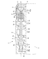
- FIG. 3 is a sectional view taken along the line AA of FIG.
- the lower body 2 includes a pressure regulator valve (control valve for control) 6 that regulates the line pressure PL that is the main pressure of the hydraulic oil of the automatic transmission AT, and a lockup control valve (control) that controls the operation of a lockup clutch (not shown).
- Control valve) 7 etc. are housed.
- a plurality of solenoids 5 for generating control pressure for controlling the pressure regulator valve 6, the lockup control valve 7, and the like are arranged on the side surface of the lower body 2.
- the lower body 2 of the control valve assembly 1 is integrated with the upper body 3 via a separate plate 4 by a plurality of fastening bolts B.
- the lower body 2 including the pressure regulator valve 6 for adjusting the pressure of the hydraulic oil of the automatic transmission AT is provided with a drain port 2a for adjusting the pressure.
- a rib R on the outer surface of the lower body 2, parallel to the axial center P of the spool 9 of the pressure regulator valve 6) straddling the drain port 2a ( The reinforcing portion) is formed to have a length substantially the same as the axial length of the spool 9.
- a bore 10 is formed inside the lower body 2, and the spool 9 of the pressure regulator valve 6 is housed in the bore 10.
- the adapter 11 is press-fitted and fixed to the right end portion in the drawing.
- the spool 9 is slidably housed in the bore 10 via a spring 8 arranged between the adapter 11 and the land 9d of the spool 9.
- the lower body 2 between the adapter 11 and the land 9d of the spool 9 is formed with a port 2f to which hydraulic oil of the solenoid pressure Psol for line pressure control controlled by the solenoid 5 for line pressure control is supplied.
- a port 2e for supplying the hydraulic oil of the torque converter pressure Pt to a torque converter (not shown) is formed in the lower body 2 between the lands 9d and the lands 9c of the spool 9. Further, the lower body 2 between the lands 9c and the lands 9b of the spool 9 is formed with a port 2d to which the hydraulic oil of the oil pump discharge pressure discharged by the oil pump (not shown) is supplied.
- the spool 9 of the pressure regulator valve 6 is an oil pump due to the balance between the line pressure control solenoid pressure Psol supplied to the port 2f and the urging force of the spring 8 and the feedback pressure Pfb (line pressure PL) supplied to the feedback port 2b.
- the line pressure PL is adjusted and generated by discharging the hydraulic oil of the discharge pressure to the drain port 2a and the port 2e formed in the lower body 2 between the lands 9b and the lands 9a of the spool 9.
- the drain port 2c discharges the leaked hydraulic oil.
- the drain port 2a is closed by the rib R.
- the drain port 2a since the drain port 2a is open in the direction orthogonal to the axial center P of the spool 9, there is no problem with the operation of the pressure regulator valve 6. As a result, the rigidity in the vicinity of the drain port 2a that communicates the inside and the outside of the control valve assembly 1 can be increased, and large deformation can be suppressed.
- the automatic transmission AT including the control valve assembly 1 of the first embodiment has the effects listed below.
- a rib R is formed on the outer surface of the lower body 2 in parallel with the axial center P of the spool 9 of the pressure regulator valve 6 and straddling the drain port 2a having a length substantially the same as the axial length of the spool 9. I made it. Therefore, the rigidity in the vicinity where the drain port 2a is formed can be increased, and large deformation can be suppressed.
Landscapes
- Engineering & Computer Science (AREA)
- General Engineering & Computer Science (AREA)
- Mechanical Engineering (AREA)
- Control Of Transmission Device (AREA)
Priority Applications (3)
| Application Number | Priority Date | Filing Date | Title |
|---|---|---|---|
| US17/442,266 US20220154818A1 (en) | 2019-03-27 | 2019-11-13 | Automatic transmission |
| JP2021508715A JP7202446B2 (ja) | 2019-03-27 | 2019-11-13 | 自動変速機 |
| CN201980093893.XA CN113557383B (zh) | 2019-03-27 | 2019-11-13 | 自动变速器 |
Applications Claiming Priority (2)
| Application Number | Priority Date | Filing Date | Title |
|---|---|---|---|
| JP2019059694 | 2019-03-27 | ||
| JP2019-059694 | 2019-03-27 |
Publications (1)
| Publication Number | Publication Date |
|---|---|
| WO2020194847A1 true WO2020194847A1 (ja) | 2020-10-01 |
Family
ID=72611264
Family Applications (1)
| Application Number | Title | Priority Date | Filing Date |
|---|---|---|---|
| PCT/JP2019/044468 Ceased WO2020194847A1 (ja) | 2019-03-27 | 2019-11-13 | 自動変速機 |
Country Status (4)
| Country | Link |
|---|---|
| US (1) | US20220154818A1 (https=) |
| JP (1) | JP7202446B2 (https=) |
| CN (1) | CN113557383B (https=) |
| WO (1) | WO2020194847A1 (https=) |
Citations (3)
| Publication number | Priority date | Publication date | Assignee | Title |
|---|---|---|---|---|
| JPS6062643U (ja) * | 1983-10-06 | 1985-05-01 | 日産自動車株式会社 | 自動変速機のバルブボデイ |
| JPH02110750U (https=) * | 1989-02-22 | 1990-09-05 | ||
| US5235746A (en) * | 1992-03-19 | 1993-08-17 | Atlas Fluid Controls Inc. | Method of manufacturing a high-capacity servo valve body |
Family Cites Families (4)
| Publication number | Priority date | Publication date | Assignee | Title |
|---|---|---|---|---|
| JP3670024B2 (ja) * | 1993-03-19 | 2005-07-13 | ジヤトコ株式会社 | 変速機の油圧制御装置 |
| JP4861455B2 (ja) * | 2009-07-15 | 2012-01-25 | ジヤトコ株式会社 | 自動変速機 |
| DE102013221218A1 (de) * | 2013-10-18 | 2015-04-23 | Robert Bosch Gmbh | Schieberventil, insbesondere für ein Automatikgetriebe eines Kraftfahrzeugs |
| US10302191B2 (en) * | 2015-07-21 | 2019-05-28 | Mazda Motor Corporation | Automatic transmission and method of manufacturing the same |
-
2019
- 2019-11-13 JP JP2021508715A patent/JP7202446B2/ja active Active
- 2019-11-13 CN CN201980093893.XA patent/CN113557383B/zh active Active
- 2019-11-13 WO PCT/JP2019/044468 patent/WO2020194847A1/ja not_active Ceased
- 2019-11-13 US US17/442,266 patent/US20220154818A1/en not_active Abandoned
Patent Citations (3)
| Publication number | Priority date | Publication date | Assignee | Title |
|---|---|---|---|---|
| JPS6062643U (ja) * | 1983-10-06 | 1985-05-01 | 日産自動車株式会社 | 自動変速機のバルブボデイ |
| JPH02110750U (https=) * | 1989-02-22 | 1990-09-05 | ||
| US5235746A (en) * | 1992-03-19 | 1993-08-17 | Atlas Fluid Controls Inc. | Method of manufacturing a high-capacity servo valve body |
Also Published As
| Publication number | Publication date |
|---|---|
| CN113557383B (zh) | 2023-03-14 |
| JPWO2020194847A1 (https=) | 2020-10-01 |
| CN113557383A (zh) | 2021-10-26 |
| US20220154818A1 (en) | 2022-05-19 |
| JP7202446B2 (ja) | 2023-01-11 |
Similar Documents
| Publication | Publication Date | Title |
|---|---|---|
| EP2912322B1 (en) | Electro-hydraulic pressure reducing and relieving valve with flow force control for large flow capacity | |
| EP2837832A1 (en) | Relief valve | |
| WO2014102273A1 (en) | Hydraulically actuated continuously variable transmission | |
| US20150316149A1 (en) | Continuously variable transmission with a hydraulic control system | |
| KR100376692B1 (ko) | 차량용 자동변속기 유압 제어 시스템의 매뉴얼 밸브 | |
| US6681794B2 (en) | Unloading valve | |
| EP3892865B1 (en) | Valve spool with flow force mitigation features | |
| US20180172146A1 (en) | Valve body for hydraulic control device, and production method therefor | |
| US12291848B2 (en) | Flow control valve | |
| WO2020194847A1 (ja) | 自動変速機 | |
| DE102009034047B4 (de) | Kettenantriebsspannersystem mit variablem Durchlass | |
| DE102015113516B4 (de) | Ventileinstellsteuerung | |
| DE102018218301A1 (de) | Verdrängungssteuerungsvorrichtung | |
| EP2107277B1 (en) | Hydraulic control valve apparatus for automatic transmission | |
| KR20210028566A (ko) | 압력 조정 밸브 및 건설 기계 | |
| JP7091681B2 (ja) | 制御弁 | |
| CN108930681B (zh) | 一种分段控制的平衡阀 | |
| CN110088486B (zh) | 液压伺服机构 | |
| US12480587B2 (en) | Hydraulic control unit valve porting, routing, checkball, and orifice integration with additive manufacturing | |
| KR20200055097A (ko) | 릴리프 밸브 | |
| JP2018025228A (ja) | コントロールバルブユニット | |
| US10480642B2 (en) | Multi speed transmission device with hydraulically actuated shift rods | |
| KR100461751B1 (ko) | 라인압 제어용 레귤레이터 밸브 | |
| KR20240044222A (ko) | 필터가 설치된 유압장치 | |
| JP5569296B2 (ja) | 油圧開放弁 |
Legal Events
| Date | Code | Title | Description |
|---|---|---|---|
| 121 | Ep: the epo has been informed by wipo that ep was designated in this application |
Ref document number: 19920671 Country of ref document: EP Kind code of ref document: A1 |
|
| ENP | Entry into the national phase |
Ref document number: 2021508715 Country of ref document: JP Kind code of ref document: A |
|
| NENP | Non-entry into the national phase |
Ref country code: DE |
|
| 122 | Ep: pct application non-entry in european phase |
Ref document number: 19920671 Country of ref document: EP Kind code of ref document: A1 |