WO2020189684A1 - エンジンの冷却装置 - Google Patents
エンジンの冷却装置 Download PDFInfo
- Publication number
- WO2020189684A1 WO2020189684A1 PCT/JP2020/011772 JP2020011772W WO2020189684A1 WO 2020189684 A1 WO2020189684 A1 WO 2020189684A1 JP 2020011772 W JP2020011772 W JP 2020011772W WO 2020189684 A1 WO2020189684 A1 WO 2020189684A1
- Authority
- WO
- WIPO (PCT)
- Prior art keywords
- oil
- engine
- temperature
- cooler
- oil passage
- Prior art date
- Legal status (The legal status is an assumption and is not a legal conclusion. Google has not performed a legal analysis and makes no representation as to the accuracy of the status listed.)
- Ceased
Links
Images








Classifications
-
- F—MECHANICAL ENGINEERING; LIGHTING; HEATING; WEAPONS; BLASTING
- F01—MACHINES OR ENGINES IN GENERAL; ENGINE PLANTS IN GENERAL; STEAM ENGINES
- F01M—LUBRICATING OF MACHINES OR ENGINES IN GENERAL; LUBRICATING INTERNAL COMBUSTION ENGINES; CRANKCASE VENTILATING
- F01M1/00—Pressure lubrication
- F01M1/02—Pressure lubrication using lubricating pumps
-
- F—MECHANICAL ENGINEERING; LIGHTING; HEATING; WEAPONS; BLASTING
- F01—MACHINES OR ENGINES IN GENERAL; ENGINE PLANTS IN GENERAL; STEAM ENGINES
- F01M—LUBRICATING OF MACHINES OR ENGINES IN GENERAL; LUBRICATING INTERNAL COMBUSTION ENGINES; CRANKCASE VENTILATING
- F01M1/00—Pressure lubrication
- F01M1/16—Controlling lubricant pressure or quantity
-
- F—MECHANICAL ENGINEERING; LIGHTING; HEATING; WEAPONS; BLASTING
- F01—MACHINES OR ENGINES IN GENERAL; ENGINE PLANTS IN GENERAL; STEAM ENGINES
- F01M—LUBRICATING OF MACHINES OR ENGINES IN GENERAL; LUBRICATING INTERNAL COMBUSTION ENGINES; CRANKCASE VENTILATING
- F01M5/00—Heating, cooling, or controlling temperature of lubricant; Lubrication means facilitating engine starting
-
- F—MECHANICAL ENGINEERING; LIGHTING; HEATING; WEAPONS; BLASTING
- F01—MACHINES OR ENGINES IN GENERAL; ENGINE PLANTS IN GENERAL; STEAM ENGINES
- F01M—LUBRICATING OF MACHINES OR ENGINES IN GENERAL; LUBRICATING INTERNAL COMBUSTION ENGINES; CRANKCASE VENTILATING
- F01M7/00—Lubrication means specially adapted for machine or engine running-in
-
- F—MECHANICAL ENGINEERING; LIGHTING; HEATING; WEAPONS; BLASTING
- F01—MACHINES OR ENGINES IN GENERAL; ENGINE PLANTS IN GENERAL; STEAM ENGINES
- F01P—COOLING OF MACHINES OR ENGINES IN GENERAL; COOLING OF INTERNAL-COMBUSTION ENGINES
- F01P3/00—Liquid cooling
- F01P3/18—Arrangements or mounting of liquid-to-air heat-exchangers
-
- F—MECHANICAL ENGINEERING; LIGHTING; HEATING; WEAPONS; BLASTING
- F01—MACHINES OR ENGINES IN GENERAL; ENGINE PLANTS IN GENERAL; STEAM ENGINES
- F01P—COOLING OF MACHINES OR ENGINES IN GENERAL; COOLING OF INTERNAL-COMBUSTION ENGINES
- F01P7/00—Controlling of coolant flow
- F01P7/14—Controlling of coolant flow the coolant being liquid
- F01P7/16—Controlling of coolant flow the coolant being liquid by thermostatic control
Definitions
- the present disclosure relates to an engine cooling device, and more particularly to an engine cooling device including an electric oil pump.
- Patent Document 1 discloses a technique in which a mechanical oil pump driven by the power of an engine and an electric oil pump are provided side by side, and the electric oil pump is driven after a certain period of time has elapsed after the engine is stopped. ing.
- the technology of the present disclosure aims to effectively suppress the temperature rise of the lubricating element of the engine after the engine is stopped.
- the technique of the present disclosure is supplied to an oil storage unit that stores engine oil, a main oil passage that connects the oil storage unit and an oil gallery that supplies the engine oil to the lubricating element of the engine, and the lubricating element.
- a return oil passage for returning the engine oil to the oil storage portion a mechanical pump provided in the main oil passage, driven by the power of the engine, and pumping and pumping the engine oil from the oil storage portion.
- the upstream end is connected to the upstream side of the main oil passage with respect to the mechanical pump or the oil storage portion, and the downstream end is connected to the downstream side of the main oil passage with respect to the mechanical pump.
- a pump bypass oil passage that bypasses the mechanical pump, an electric pump that is provided in the pump bypass oil passage and pumps and pumps the engine oil from the oil storage unit, and an oil that obtains the oil temperature of the engine oil.
- an oil cooler provided in the main oil passage and a cooler bypass oil passage that branches from the main oil passage on the upstream side of the oil cooler and joins the main oil passage on the downstream side of the oil cooler.
- a switching valve for switching the flow path of the engine oil to the main oil passage provided with the oil cooler or the cooler bypass oil passage is further provided, and the control unit receives the oil temperature acquired when the engine is stopped.
- the flow path of the engine oil is set as the main oil passage provided with the oil cooler, and is acquired when the engine is stopped.
- the oil temperature is equal to or lower than the second threshold temperature, it is preferable to execute the flow path switching control in which the flow path of the engine oil is the cooler bypass oil passage.
- a water temperature sensor for acquiring the water temperature of the cooling water of the cooling water circuit of the engine and an electric water pump provided in the cooling water circuit for circulating the cooling water are further provided, and the control unit is the control unit.
- the electric water pump is driven if the acquired water temperature is equal to or higher than a predetermined threshold water temperature. It is preferable to carry out cooling water circulation control.
- an oil cooler provided in the main oil passage and a cooler bypass oil passage that branches from the main oil passage on the upstream side of the oil cooler and joins the main oil passage on the downstream side of the oil cooler.
- a switching valve for switching the flow path of the engine oil to the main oil passage provided with the oil cooler or the cooler bypass oil passage, and a water temperature sensor for acquiring the temperature of the cooling water of the cooling water circuit of the engine.
- the control unit sets the flow path of the engine oil as the main oil passage provided with the oil cooler.
- the oil temperature acquired when the engine is stopped is equal to or lower than the water temperature at which the oil temperature is acquired, it is preferable to execute flow path switching control in which the flow path of the engine oil is the cooler bypass oil passage.
- an electric water pump provided in the cooling water circuit to circulate the cooling water is further provided, and the control unit is provided with the oil cooler in the flow path of the engine oil by the flow path switching valve.
- the control unit is provided with the oil cooler in the flow path of the engine oil by the flow path switching valve.
- FIG. 1 is a schematic overall configuration diagram of an engine provided with a cooling device according to the first embodiment and its peripheral configuration.
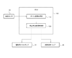
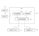
- FIG. 2 is a schematic functional block diagram showing an electronic control unit according to the first embodiment and related peripheral configurations.
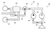
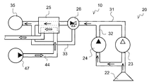
- FIG. 3A is a diagram schematically showing the circulation of engine oil passing through the oil cooler of the cooling device according to the first embodiment.
- FIG. 3B is a diagram schematically showing the circulation of engine oil bypassing the oil cooler of the cooling device according to the first embodiment.
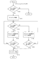
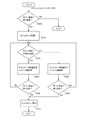
- FIG. 4 is a flowchart showing the stop oil circulation control and the flow path selection control according to the first embodiment.
- FIG. 5 is a diagram schematically showing the time-series changes in the engine rotation speed, the oil pump rotation speed, and the oil pressure of the engine oil when the engine according to the comparative example is stopped.
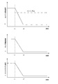
- FIG. 6 is a diagram schematically showing time-series changes in the engine rotation speed, the oil pump rotation speed, and the oil pressure of the engine oil when the engine according to the first embodiment is stopped.
- FIG. 7 is a schematic functional block diagram showing an electronic control unit according to a second embodiment and related peripheral configurations.
- FIG. 8A is a diagram schematically showing the circulation of engine oil passing through the oil cooler of the cooling device according to the second embodiment.
- FIG. 8B is a diagram schematically showing the circulation of engine oil bypassing the oil cooler of the cooling device according to the second embodiment.
- FIG. 8C is a diagram schematically showing the circulation of engine oil and the circulation of cooling water passing through the oil cooler of the cooling device according to the second embodiment.
- FIG. 8A is a diagram schematically showing the circulation of engine oil passing through the oil cooler of the cooling device according to the second embodiment.
- FIG. 8B is a diagram schematically showing the circulation of engine oil bypassing the oil cooler of the cooling device according to the second embodiment.
- FIG. 8C is
- FIG. 9 is a flowchart showing a stop oil circulation control, a flow path selection control, and a stop cooling water circulation control according to the second embodiment.
- FIG. 10 is a schematic functional block diagram showing an electronic control unit according to a third embodiment and related peripheral configurations.
- FIG. 11 is a flowchart showing a stop oil circulation control and a flow path selection control according to the third embodiment.
- FIG. 12 is a schematic functional block diagram showing an electronic control unit according to a fourth embodiment and related peripheral configurations.
- FIG. 13 is a flowchart showing a stop oil circulation control, a flow path selection control, and a stop cooling water circulation control according to the fourth embodiment.
- FIG. 1 is a schematic overall configuration diagram of an engine provided with a cooling device according to the present embodiment and its peripheral configuration.
- the engine 1 includes an engine main body 2, a lubricating oil circuit 20, a cooling water circuit 40, and an electronic control unit (hereinafter, ECU) 100 (control unit). There is.
- ECU electronice control unit
- the engine body 2 mainly includes a cylinder head 3 and a cylinder block 4.
- the cylinder block 4 is provided with an oil gallery 35 that supplies engine oil to the lubrication elements 61 to 63 of the engine 1. Further, the cylinder block 4 is provided with a cylinder C for accommodating the piston P so as to be reciprocally movable.
- FIG. 1 shows only one of the plurality of cylinders of the engine 1, and the other cylinders are not shown.
- the engine 1 may be either a plurality of cylinders or a single cylinder.
- a piston ring PR that is in sliding contact with the inner wall of the cylinder C is mounted on the outer circumference of the piston P.
- Engine oil discharged from the oil gallery 35 via the oil jet 70 is supplied to the sliding contact surface between the piston P (piston ring PR) and the cylinder C and the cooling channel (not shown) of the piston P.
- These sliding contact surfaces and cooling channels are examples of the lubricating elements of the present disclosure.
- a crankcase portion 4A is provided at the bottom of the cylinder block 4.
- a crankshaft 62 is connected to the piston P via a connecting rod CR, and the reciprocating motion of the piston P is converted into a rotary motion and transmitted to the crankshaft 62.
- Engine oil is supplied from the oil gallery 35 to the journal and the crank pin (an example of the lubricating element of the present disclosure) of the crankshaft 62 via an oil passage (not shown).
- An oil pan 21 for storing engine oil is provided in the lower part of the crankcase portion 4A.
- a cylinder head 3 is provided on the upper part of the cylinder block 4.
- the cylinder head 3 is provided with an intake port 5 for introducing intake air into the cylinder C and an exhaust port 6 for drawing out exhaust gas from the inside of the cylinder C.
- the cylinder head 3 is provided with an intake valve 7 for opening and closing the intake port 5 and an exhaust valve 8 for opening and closing the exhaust port 6.
- the intake valve 7 and the exhaust valve 8 are opened and closed by a valve operating mechanism 61 provided on the upper part of the cylinder head 3.
- Engine oil is supplied from the oil gallery 35 to the valve operating mechanism 61 (an example of the lubricating element of the present disclosure).
- the cylinder head 3 is provided with an injector 9 for directly injecting fuel into the cylinder C.
- the engine 1 is not limited to the direct injection engine, and may be a premixed engine.
- An intake manifold 11 communicating with the intake port 5 is provided on the intake side of the cylinder head 3.
- An intake passage 12 for introducing intake air is connected to the intake manifold 11.
- the intake passage 12 is provided with a compressor 63A or the like of the supercharger 63.
- An exhaust manifold 13 communicating with the exhaust port 6 is provided on the exhaust side of the cylinder head 3.
- An exhaust passage 14 that guides exhaust gas to the atmosphere is connected to the exhaust manifold 13.
- the exhaust passage 14 is provided with a turbine 63B or the like of the turbocharger 63.
- the supercharger 63 includes a turbine 63B driven by exhaust gas, and a compressor 63A connected to the turbine 63B by a rotating shaft 63C to pump intake air.
- the supercharger 63 is not limited to the conventional type shown in the illustrated example, and may be a variable capacitance type having variable wings.
- Engine oil is supplied from the oil gallery 35 to the rotary shaft 63C of the turbocharger 63 and the bearing portion (not shown) (an example of the lubrication element of the present disclosure) through an oil passage (not shown).
- the lubricating oil circuit 20 includes an oil pan 21 (oil storage portion), an oil strainer 22, a mechanical oil pump 23 (mechanical pump), an electric oil pump 24 (electric pump), an oil cooler 25, and the like.
- a main oil passage 31, an upstream bypass oil passage 32 (pump bypass oil passage), an oil passage switching valve 26 (switching valve), a return oil passage 29, and a downstream bypass oil passage 33 (cooler bypass oil passage) are provided. ing.
- the oil pan 21 stores engine oil.
- the engine oil is returned to the oil pan 21 after lubricating each of the lubricating elements 61 to 63.
- the oil strainer 22 is a filter for removing foreign substances contained in the engine oil, and is immersed in the engine oil in the oil pan 21.
- a main oil passage 31 is connected to the oil strainer 22.
- the main oil passage 31 connects the oil strainer 22 and the oil gallery 35.
- the main oil passage 31 is provided with a mechanical oil pump 23, an oil cooler 25, an oil filter 28, and the like that pump up and pump the engine oil in the oil pan 11 in order from the upstream side in the flow direction of the engine oil. ..
- the mechanical oil pump 23 is connected to the crankshaft 62 via a belt pulley or the like (not shown), and is driven by the power of the engine 1.
- the engine oil pumped by the mechanical oil pump 23 through the main oil passage 31 is supplied from the oil gallery 35 to each of the lubricating elements 61 to 63.
- the oil cooler 25 cools the engine oil by exchanging heat between the engine oil distributed inside the oil cooler 25 and the cooling water.
- the oil filter 28 removes foreign matter contained in the engine oil pumped by the mechanical oil pump 23 or the electric oil pump 24, and the filter element 28B functioning as a filter medium is housed in the housing 28A. There is.
- the upstream bypass oil passage 32 branches from the upstream side of the mechanical oil pump 23 of the main oil passage 31 and joins the main oil passage 31 between the mechanical oil pump 23 and the oil cooler 25. That is, the upstream bypass oil passage 32 is a flow path for diverting engine oil from the mechanical oil pump 23.
- the upstream bypass oil passage 32 is provided with an electric oil pump 24 that pumps up and pumps engine oil in the oil pan 21.
- the upstream bypass oil passage 32 may be directly immersed in the engine oil in the oil pan 21 without connecting the upstream end and the main oil passage 31.
- the electric oil pump 24 is an electric pump driven by electric power supplied from the battery 200, and its drive is controlled in response to a command from the ECU 100.
- a check valve 27 for preventing the backflow of engine oil is provided on the downstream side of the upstream bypass oil passage 32 with respect to the electric oil pump 24.
- the downstream bypass oil passage 33 branches from the downstream side of the confluence of the main oil passage 31 with the upstream bypass oil passage 32 and from the upstream side of the oil cooler 25, and with the main oil passage 31 on the downstream side of the oil cooler 25. It is merging and diverts engine oil from the oil cooler 25.
- An oil passage switching valve 26 is provided at a branch portion between the downstream bypass oil passage 33 and the main oil passage 31.
- the oil passage switching valve 26 is a three-way valve such as an electronically controlled valve that can switch the flow path of engine oil between the main oil passage 31 and the downstream bypass oil passage 33, and its operation is controlled in response to a command from the ECU 100. Will be done.
- the oil passage switching valve 26 may be provided at the confluence of the main oil passage 31 and the downstream bypass oil passage 33.
- the return oil passage 29 is a flow path for returning the engine oil supplied to each of the lubricating elements 61 to 63 to the oil pan 21.
- the cooling water circuit 40 includes a radiator 41, a water jacket 42 formed in the cylinder block 4, an upstream pipe 43 connecting the outlet portion of the water jacket 42 and the inlet portion of the radiator 41, and the outlet portion and water of the radiator 41. It is provided at a downstream pipe 44 that connects the inlet portion of the jacket 42, a bypass pipe 45 that connects the upstream pipe 43 and the downstream pipe 44 and bypasses the radiator 41, and a branch portion between the upstream pipe 43 and the bypass pipe 45. It is equipped with a thermostat 46 and a water pump 47 (electric water pump) for pumping cooling water.
- the water pump 47 is an electric pump driven by electric power supplied from the battery 200, and its drive is controlled in response to a command from the ECU 100.
- a water temperature sensor 50 that acquires the temperature of the cooling water flowing from the water jacket 42 into the upstream pipe 43 (hereinafter referred to as the cooling water temperature TW) is provided near the outlet of the water jacket 42.
- the oil gallery 35 is provided with an oil temperature sensor 51 that acquires the temperature of the engine oil flowing in the oil gallery 35 (hereinafter, oil temperature TO).
- oil temperature TO oil temperature
- FIG. 2 is a schematic functional block diagram showing the ECU 100 according to the first embodiment and related peripheral configurations.
- the ECU 100 performs various controls such as the engine 1, and is configured to include a known CPU (Central Processing Unit), ROM (Read Only Memory), RAM (Random Access Memory), input port, output port, and the like. .. Further, the ECU 100 includes an oil temperature acquisition unit 110 and a stopped oil circulation control unit 120 as some functional elements. Each of these functional elements will be described as being included in the ECU 100, which is integrated hardware in the present embodiment, but any part of them may be provided in separate hardware.
- the oil temperature acquisition unit 110 acquires the oil temperature TO transmitted from the oil temperature sensor 51.
- the oil temperature TO acquired by the oil temperature acquisition unit 110 is transmitted to the stopped oil circulation control unit 120.
- the stop oil circulation control unit 120 drives the electric oil pump 24 to circulate the engine oil in the lubricating oil circuit 20 when the engine 1 is requested to stop. Take control.
- the stopped oil circulation control is an electric oil pump when the oil temperature TO acquired by the oil temperature acquisition unit 110 exceeds a predetermined first threshold temperature T1 (for example, 50 ° C.).
- a predetermined first threshold temperature T1 for example, 50 ° C.
- 24 is driven to supply engine oil from the main oil passage 31 to each lubricating element via the oil cooler 25 as shown in FIG. 3A, or engine oil is supplied from the main oil passage 31 through the main oil passage 31 as shown in FIG. 3B. It is carried out by bypassing the cooler 25 and supplying each lubricating element.
- the first threshold temperature T1 is obtained by acquiring in advance the oil temperature that causes the temperature of each lubricating element to rise sharply when the supply of engine oil to each lubricating element is stopped due to the stop of the engine 1. You can set it.
- the electric oil pump 24 is driven to supply engine oil to the lubrication elements 61 to 63, whereby the lubrication elements 61
- the oil temperature TO is equal to or lower than the first threshold temperature T1 while preventing the temperature from rising to 63, wasteful power consumption can be suppressed by not driving the electric oil pump 24.
- stopped oil circulation control unit 120 passes through the engine oil flow path through the oil cooler 25 based on the oil temperature TO transmitted from the oil temperature acquisition unit 110 when executing the above-mentioned stopped oil circulation control.
- the flow path selection control for selecting from the flow path or the flow path bypassing the oil cooler 25 is executed.
- the flow path selection control is as shown in FIG. 3A when the oil temperature TO exceeds a predetermined second threshold temperature T2 (for example, 80 ° C.) higher than the first threshold temperature T1.
- the oil passage switching valve 26 is controlled so that the engine oil passes through the oil cooler 25.
- the oil temperature TO is equal to or lower than the second threshold temperature T2
- the engine oil is the oil cooler as shown in FIG. 3B. It is executed by controlling the oil passage switching valve 26 so as to bypass 25.
- the second threshold temperature T2 is the upper limit oil temperature in which the engine oil is in a relatively high temperature state and it takes time to cool even if the high temperature engine oil is supplied to each lubricating element by experiments or the like in advance. You can set it by getting it.
- the oil temperature TO exceeds the second threshold temperature T2
- the oil temperature TO is compared by supplying the engine oil cooled by passing through the oil cooler 25 to each of the lubricating elements 61 to 63. While cooling each lubricating element at an early stage even in the case of a target high temperature, when the oil temperature TO is equal to or lower than the second threshold temperature T2, engine oil bypassing the oil cooler 25 is supplied to each lubricating element 61 to 63. As a result, unnecessary heat exchange between the engine oil and the cooling water can be prevented.
- the above-mentioned stopped oil circulation control is preferably terminated by stopping the driving of the electric oil pump 24 when the oil temperature TO transmitted from the oil temperature acquisition unit 110 drops to the first threshold temperature T1.
- step S100 it is determined whether or not the oil temperature TO exceeds a predetermined first threshold temperature (for example, 50 ° C.) based on the sensor value of the oil temperature sensor 51. If yes, the control proceeds to step S110, and if no, the control ends without performing stop oil circulation control.
- a predetermined first threshold temperature for example, 50 ° C.
- step S110 the electric power of the battery 200 is supplied to the electric oil pump 24 to drive the electric oil pump 24.
- the electric oil pump 24 is driven, engine oil is pumped from the oil pan 21 and pumped.
- step S120 it is determined whether or not the oil temperature TO exceeds a predetermined second threshold temperature (for example, 80 ° C.) based on the sensor value of the oil temperature sensor 51. If yes, the control proceeds to step S130, and if no, the control proceeds to step S150.
- a predetermined second threshold temperature for example, 80 ° C.
- step S130 the oil passage switching valve 26 is controlled so that the engine oil passes through the oil cooler 25, and the engine oil is controlled to flow from the main oil passage 31 to the oil cooler 25. That is, after the engine oil is cooled by the oil cooler 25, it is supplied from the oil gallery 35 to each of the lubricating elements 61 to 63.
- step S140 it is determined whether or not the oil temperature TO has dropped to a predetermined first threshold temperature based on the sensor value of the oil temperature sensor 51. If yes, the control proceeds to step S170, the electric oil pump 24 is stopped, and the control ends. On the other hand, in the case of negation (No), this control returns to step S120.
- step S120 if the oil temperature TO is equal to or lower than the predetermined second threshold temperature, this control proceeds to step S150.
- step S150 the oil passage switching valve 26 is controlled so that the engine oil bypasses the oil cooler 25, and the engine oil is controlled to flow from the main oil passage 31 to the downstream bypass oil passage 33. That is, after the engine oil bypasses the oil cooler 25, it is supplied from the oil gallery 35 to each of the lubricating elements 61 to 63.
- step S160 it is determined whether or not the oil temperature TO has dropped to a predetermined first threshold temperature based on the sensor value of the oil temperature sensor 51. If yes, the control proceeds to step S170, the electric oil pump 24 is stopped, and the control ends. On the other hand, in the case of negation (No), this control returns to step S120.
- FIG. 5 shows the engine rotation speed after the engine is stopped, the oil pump rotation speed, and the oil pressure of the engine oil in the oil gallery for the engine according to the comparative example in which only the mechanical oil pump is provided and the electric oil pump is not provided.
- the engine of the comparative example when the engine stop request is made by the OFF operation of the ignition switch and the engine is stopped (see time t1), the rotation speed of the mechanical oil pump gradually decreases. Therefore, the oil pressure of the engine oil in the oil gallery decreases with the passage of time (see times t1 to t2), and the engine oil is gradually not supplied to each of the lubricating elements 61 to 63 of the engine. As a result, the temperature of each of the lubricating elements 61 to 63 rises sharply, which may cause a failure of each of the lubricating elements 61 to 63.
- the oil temperature TO becomes the second.
- the electric oil pump 24 is driven to keep the oil pressure of the engine oil at a constant height in the oil gallery 35 (see time t2 to t3), and each lubrication element. It is configured to supply engine oil to 61-63.
- the cooling device 10 it is possible to effectively prevent the temperature of each of the lubricating elements 61 to 63 of the engine 1 from rising after the engine 1 is stopped, and these lubricating elements can be effectively prevented from rising. It is possible to prevent failures of 61 to 63. Further, when the engine oil is supplied, if the oil temperature TO exceeds the second threshold temperature, the engine oil cooled by passing through the oil cooler 25 is supplied to the respective lubrication elements 61 to 63 to provide each lubrication. Early cooling of the elements 61 to 63 can be achieved, and the cooling time of each of the lubricating elements 61 to 63 can be surely shortened even when the oil temperature TO is high.
- FIG. 7 is a schematic functional block diagram showing the ECU 100 according to the second embodiment and related peripheral configurations.
- the ECU 100 according to the second embodiment is the one in which the cooling water temperature acquisition unit 130 and the cooling water circulation control unit 140 at the time of stop are added to the ECU 100 of the first embodiment. Since other functional elements have the same functions as those in the first embodiment, detailed description thereof will be omitted.
- the cooling water temperature acquisition unit 130 acquires the cooling water temperature TW transmitted from the water temperature sensor 50.
- the cooling water temperature TW acquired by the cooling water temperature acquisition unit 130 is transmitted to the cooling water circulation control unit 140 when stopped.
- the stop oil circulation control unit 120 drives the electric oil pump 24 when the oil temperature TO exceeds the first threshold temperature T1 when the stop request of the engine 1 is made by the OFF operation of the ignition switch 150. Then, the stop oil circulation control for circulating the engine oil in the lubricating oil circuit 20 is executed (see FIGS. 8A and 8B). Further, when the oil temperature TO exceeds the second threshold temperature T2, the stopped oil circulation control unit 120 supplies the cooled engine oil through the oil cooler 25 to each of the lubricating elements 61 to 63. The road selection control is executed (see FIG. 8A). Since the details of the oil circulation control at the time of stop have already been explained in the first embodiment, further description will be omitted.
- the cooling water circulation control unit 140 at the time of stop is requested to stop the engine 1 by the OFF operation of the ignition switch 150, and the oil circulation control unit 120 at the time of stop passes the oil cooler 25 to pass the engine oil to each lubrication element 61 to.
- the cooling water circulation control at the time of stop driving the water pump 47 is executed based on the cooling water temperature TW transmitted from the cooling water temperature acquisition unit 130.
- the cooling water circulation control unit 140 at the time of stopping is a water when the cooling water temperature TW acquired by the cooling water temperature acquisition unit 130 exceeds a predetermined third threshold temperature T3 (for example, 40 ° C.).
- the pump 47 is driven, and as shown in FIG. 8C, a stop cooling water circulation control is executed in which the cooling water is circulated to the cooling water circuit 40 (both shown in FIG. 1) including the radiator 41.
- the oil circulation control at the time of stopping is executed by the stop request of the engine 1, and when the high temperature engine oil is passed through the oil cooler 25, the cooling water whose flow is stopped becomes the engine oil.
- the temperature that can be boiled by the heat exchange of the above may be set as a reference.
- step S200 it is determined whether or not the oil temperature TO exceeds a predetermined first threshold temperature (for example, 50 ° C.) based on the sensor value of the oil temperature sensor 51. If yes, the control proceeds to step S210, and if no, the control ends without performing stop oil circulation control.
- a predetermined first threshold temperature for example, 50 ° C.
- step S210 the electric power of the battery 200 is supplied to the electric oil pump 24 to drive the electric oil pump 24.
- the electric oil pump 24 is driven, engine oil is pumped from the oil pan 21 and pumped.
- step S220 it is determined whether or not the oil temperature TO exceeds a predetermined second threshold temperature (for example, 80 ° C.) based on the sensor value of the oil temperature sensor 51. If yes, the control proceeds to step S230, and if no, the control proceeds to step S270.
- a predetermined second threshold temperature for example, 80 ° C.
- step S230 the oil passage switching valve 26 is controlled so that the engine oil passes through the oil cooler 25, and the engine oil is controlled to flow from the main oil passage 31 to the oil cooler 25. That is, after the engine oil is cooled by the oil cooler 25, it is supplied from the oil gallery 35 to each of the lubricating elements 61 to 63.
- step S240 it is determined whether or not the cooling water temperature TW exceeds a predetermined third threshold temperature (for example, 40 ° C.) based on the sensor value of the water temperature sensor 50. If yes, the control proceeds to step S250, and if no, the control proceeds to step S260.
- a predetermined third threshold temperature for example, 40 ° C.
- step S250 the electric power of the battery 200 is supplied to the water pump 47 to drive the water pump 47.
- the cooling water is pumped in the cooling water circuit 40.
- step S260 it is determined whether or not the oil temperature TO has dropped to a predetermined first threshold temperature based on the sensor value of the oil temperature sensor 51. If yes, the control proceeds to step S290, the electric oil pump 24 is stopped, and the control ends. On the other hand, in the case of negation (No), this control returns to step S220.
- step S220 if the oil temperature TO is equal to or lower than the predetermined second threshold temperature, this control proceeds to step S270.
- step S270 the oil passage switching valve 26 is controlled so that the engine oil bypasses the oil cooler 25, and the engine oil is controlled to flow from the main oil passage 31 to the downstream bypass oil passage 33. That is, after the engine oil bypasses the oil cooler 25, it is supplied from the oil gallery 35 to each of the lubricating elements 61 to 63.
- step S280 it is determined whether or not the oil temperature TO has dropped to a predetermined first threshold temperature based on the sensor value of the oil temperature sensor 51. If yes, the control proceeds to step S290, the electric oil pump 24 is stopped, and the control ends. On the other hand, in the case of negation (No), this control returns to step S220.
- the cooling device 10 it is possible to effectively prevent the temperature of each of the lubricating elements 61 to 63 of the engine 1 from rising after the engine 1 is stopped. Failure of the lubricating elements 61 to 63 can be prevented. Further, when the engine oil is supplied, if the oil temperature TO exceeds the second threshold temperature, the engine oil cooled by passing through the oil cooler 25 is supplied to the respective lubrication elements 61 to 63 to provide each lubrication. Early cooling of the elements 61 to 63 can be achieved, and the cooling time of each of the lubricating elements 61 to 63 can be surely shortened even when the oil temperature TO is high.
- a request to stop the engine 1 is made, and the oil circulation control unit 120 at the time of stopping passes the oil cooler 25 to lubricate the engine oil in a high temperature state.
- the cooling water temperature TW transmitted from the cooling water temperature acquisition unit 130 exceeds a predetermined third threshold temperature when circulating to 20, the cooling water circulation control unit 140 at stop drives the water pump 47. It is configured in. As a result, it is possible to effectively prevent the cooling water that has stopped flowing from boiling due to heat exchange with the engine oil in a high temperature state.
- FIG. 10 is a schematic functional block diagram showing the ECU 100 according to the third embodiment and related peripheral configurations.
- the cooling water temperature acquisition unit 130 is added to the ECU 100 of the first embodiment, and the flow path selection control of the oil circulation control unit 120 at the time of stop is controlled by the oil temperature TO and the cooling water temperature TW. It is configured to be based on the difference. Since other functional elements have the same functions as those in the first embodiment, detailed description thereof will be omitted.
- the cooling water temperature acquisition unit 130 acquires the cooling water temperature TW transmitted from the water temperature sensor 50.
- the cooling water temperature TW acquired by the cooling water temperature acquisition unit 130 is transmitted to the stopped oil circulation control unit 120.
- the stop oil circulation control unit 120 drives the electric oil pump 24 when the oil temperature TO exceeds the first threshold temperature T1 when the stop request of the engine 1 is made by the OFF operation of the ignition switch 150. Then, the stop oil circulation control for circulating the engine oil in the lubricating oil circuit 20 is executed (see FIGS. 3A and 3B). When the oil temperature TO is higher than the cooling water temperature TW, the stopped oil circulation control unit 120 passes the oil cooler 25 and cools the engine oil by heat exchange with the cooling water from each of the lubricating elements 61 to 61. The flow path selection control supplied to 63 is executed (see FIG. 3A).
- the oil passage switching valve 26 when the oil temperature TO is higher than the cooling water temperature TW, the oil passage switching valve 26 is operated so that the engine oil passes through the oil cooler 25 as shown in FIG. 3A.
- the oil temperature TO when the oil temperature TO is equal to or lower than the cooling water temperature TW, it is executed by controlling the oil passage switching valve 26 so that the engine oil bypasses the oil cooler 25 as shown in FIG. 3B. ..
- step S300 it is determined whether or not the oil temperature TO exceeds a predetermined first threshold temperature (for example, 50 ° C.) based on the sensor value of the oil temperature sensor 51. If yes, the control proceeds to step S310, and if no, the control ends without performing stop oil circulation control.
- a predetermined first threshold temperature for example, 50 ° C.
- step S310 the electric power of the battery 200 is supplied to the electric oil pump 24 to drive the electric oil pump 24.
- the electric oil pump 24 is driven, engine oil is pumped from the oil pan 21 and pumped.
- step S320 it is determined whether or not the oil temperature TO exceeds the cooling water temperature TW based on the sensor values of the oil temperature sensor 51 and the water temperature sensor 50. If yes, the control proceeds to step S330, and if no, the control proceeds to step S350.
- step S330 the oil passage switching valve 26 is controlled so that the engine oil passes through the oil cooler 25, and the engine oil is controlled to flow from the main oil passage 31 to the oil cooler 25. That is, after the engine oil is cooled by the oil cooler 25, it is supplied from the oil gallery 35 to each of the lubricating elements 61 to 63.
- step S340 it is determined whether or not the oil temperature TO has dropped to a predetermined first threshold temperature based on the sensor value of the oil temperature sensor 51. If yes, the control proceeds to step S370, the electric oil pump 24 is stopped, and the control ends. On the other hand, in the case of negation (No), this control returns to step S320.
- step S320 if the oil temperature TO is equal to or lower than the cooling water temperature TW, this control proceeds to step S350.
- step S350 the oil passage switching valve 26 is controlled so that the engine oil bypasses the oil cooler 25, and the engine oil is controlled to flow from the main oil passage 31 to the downstream bypass oil passage 33. That is, after the engine oil bypasses the oil cooler 25, it is supplied from the oil gallery 35 to each of the lubricating elements 61 to 63.
- step S360 it is determined whether or not the oil temperature TO has dropped to a predetermined first threshold temperature based on the sensor value of the oil temperature sensor 51. If yes, the control proceeds to step S370, the electric oil pump 24 is stopped, and the control ends. On the other hand, in the case of negation (No), this control returns to step S320.
- the cooling device 10 According to the cooling device 10 according to the third embodiment described in detail above, it is possible to effectively prevent the temperature of each of the lubricating elements 61 to 63 of the engine 1 from rising after the engine 1 is stopped. Failure of the lubricating elements 61 to 63 can be prevented.
- the cooling device 10 when the engine 1 is requested to stop and the oil temperature TO is higher than the cooling water temperature TW when the engine oil is circulated in the lubricating oil circuit 20.
- the oil cooler 25 By supplying the engine oil cooled by passing through the oil cooler 25 to each of the lubricating elements 61 to 63, early cooling of each of the lubricating elements 61 to 63 can be achieved, and even if the oil temperature TO is high.
- the cooling time of each of the lubricating elements 61 to 63 can be surely shortened.
- FIG. 12 is a schematic functional block diagram showing the ECU 100 according to the fourth embodiment and related peripheral configurations.
- the ECU 100 adds a stopped cooling water circulation control unit 140 to the ECU 100 of the third embodiment, and the cooling water temperature acquisition unit 130 circulates the cooling water temperature TW transmitted from the water temperature sensor 50 when stopped. It is configured to transmit to the control unit 120 and the cooling water circulation control unit 140 when stopped. Since other functional elements have the same functions as those in the third embodiment, detailed description thereof will be omitted.
- the stop oil circulation control unit 120 drives the electric oil pump 24 when the oil temperature TO exceeds the first threshold temperature T1 when the stop request of the engine 1 is made by the OFF operation of the ignition switch 150. Then, the stop oil circulation control for circulating the engine oil in the lubricating oil circuit 20 is executed (see FIGS. 8A and 8B).
- the stopped oil circulation control unit 120 passes the oil cooler 25 and cools the engine oil by heat exchange with the cooling water from each of the lubricating elements 61 to 61.
- the flow path selection control supplied to 63 is executed (see FIG. 8A).
- the cooling water circulation control unit 140 at the time of stop is requested to stop the engine 1 by the OFF operation of the ignition switch 150, and the oil circulation control unit 120 at the time of stop passes the oil cooler 25 to pass the engine oil to each lubrication element 61 to.
- the cooling water circulation control at the time of stop driving the water pump 47 is executed based on the cooling water temperature TW transmitted from the cooling water temperature acquisition unit 130.
- the cooling water circulation control unit 140 at the time of stopping is a water when the cooling water temperature TW acquired by the cooling water temperature acquisition unit 130 exceeds a predetermined third threshold temperature T3 (for example, 40 ° C.).
- the pump 47 is driven, and as shown in FIG. 8C, a stop cooling water circulation control is executed in which the cooling water is circulated to the cooling water circuit 40 (both shown in FIG. 1) including the radiator 41.
- the oil circulation control at the time of stopping is executed by the stop request of the engine 1, and when the high temperature engine oil is passed through the oil cooler 25, the cooling water whose flow is stopped becomes the engine oil.
- the temperature that can be boiled by the heat exchange of the above may be set as a reference.
- the cooling water when the cooling water whose flow has stopped can boil by heat exchange with the engine oil in a high temperature state, the cooling water is circulated by driving the water pump 47 and circulating the cooling water in the cooling water circuit 40. The boiling of the water is effectively suppressed.
- step S400 it is determined whether or not the oil temperature TO exceeds a predetermined first threshold temperature (for example, 50 ° C.) based on the sensor value of the oil temperature sensor 51. If yes, the control proceeds to step S410, and if no, the control ends without performing stop oil circulation control.
- a predetermined first threshold temperature for example, 50 ° C.
- step S410 the electric power of the battery 200 is supplied to the electric oil pump 24 to drive the electric oil pump 24.
- the electric oil pump 24 is driven, engine oil is pumped from the oil pan 21 and pumped.
- step S420 it is determined whether or not the oil temperature TO exceeds the cooling water temperature TW based on the sensor values of the oil temperature sensor 51 and the water temperature sensor 50. If yes, the control proceeds to step S430, and if no, the control proceeds to step S470.
- step S430 the oil passage switching valve 26 is controlled so that the engine oil passes through the oil cooler 25, and the engine oil is controlled to flow from the main oil passage 31 to the oil cooler 25. That is, after the engine oil is cooled by the oil cooler 25, it is supplied from the oil gallery 35 to each of the lubricating elements 61 to 63.
- step S440 it is determined whether or not the cooling water temperature TW exceeds a predetermined third threshold temperature (for example, 40 ° C.) based on the sensor value of the water temperature sensor 50. If yes, the control proceeds to step S450, and if no, the control proceeds to step S460.
- a predetermined third threshold temperature for example, 40 ° C.
- step S450 the electric power of the battery 200 is supplied to the water pump 47 to drive the water pump 47.
- the cooling water is pumped in the cooling water circuit 40.
- step S460 it is determined whether or not the oil temperature TO has dropped to a predetermined first threshold temperature based on the sensor value of the oil temperature sensor 51. If yes, the control proceeds to step S490, the electric oil pump 24 is stopped, and the control ends. On the other hand, in the case of negation (No), this control returns to step S420.
- step S420 if the oil temperature TO is equal to or lower than the cooling water temperature TW, this control proceeds to step S470.
- step S470 the oil passage switching valve 26 is controlled so that the engine oil bypasses the oil cooler 25, and the engine oil is controlled to flow from the main oil passage 31 to the downstream bypass oil passage 33. That is, after the engine oil bypasses the oil cooler 25, it is supplied from the oil gallery 35 to each of the lubricating elements 61 to 63.
- step S480 it is determined whether or not the oil temperature TO has dropped to a predetermined first threshold temperature based on the sensor value of the oil temperature sensor 51. If yes, the control proceeds to step S490, the electric oil pump 24 is stopped, and the control ends. On the other hand, in the case of negation (No), this control returns to step S420.
- the cooling device 10 it is possible to effectively prevent the temperature of each of the lubricating elements 61 to 63 of the engine 1 from rising after the engine 1 is stopped. Failure of the lubricating elements 61 to 63 can be prevented. Further, when the engine oil is supplied, if the oil temperature TO is higher than the cooling water temperature TW, the engine oil cooled by passing through the oil cooler 25 is supplied to each of the lubrication elements 61 to 63 to supply each lubrication element. Early cooling of 61 to 63 can be achieved, and the cooling time of each of the lubricating elements 61 to 63 can be reliably shortened even when the oil temperature TO is high.
- a request to stop the engine 1 is made, and the oil circulation control unit 120 at the time of stopping passes the oil cooler 25 to lubricate the engine oil in a high temperature state.
- the cooling water circulation control unit 140 at stop drives the water pump 47. It is configured in. This also makes it possible to effectively prevent the cooling water whose flow has stopped from boiling due to heat exchange with the engine oil in a high temperature state.
- the oil cooler 25 has been described as a water-cooled oil cooler that exchanges heat between cooling water and engine oil, but it may be an air-cooled oil cooler that exchanges heat between air and engine oil.
- the engine cooling device can effectively suppress the temperature rise of the lubricating element of the engine after the engine is stopped.
Landscapes
- Engineering & Computer Science (AREA)
- Mechanical Engineering (AREA)
- General Engineering & Computer Science (AREA)
- Chemical & Material Sciences (AREA)
- Combustion & Propulsion (AREA)
- Lubrication Of Internal Combustion Engines (AREA)
Abstract
エンジンオイルを貯留するオイル貯留部21と、オイル貯留部21とエンジン1の潤滑要素61~63にエンジンオイルを供給するオイルギャラリ35とを接続する主油路31と、潤滑要素61~63に供給されたエンジンオイルをオイル貯留部21に戻すリターン油路29と、主油路31に設けられると共に、エンジン1の動力で駆動し、オイル貯留部21からエンジンオイルを汲み上げて圧送する機械式ポンプ23と、機械式ポンプ23を迂回するポンプバイパス油路32と、ポンプバイパス油路32に設けられると共に、オイル貯留部21からエンジンオイルを汲み上げて圧送する電動式ポンプ24と、油温センサ51と、エンジン1の停止時に取得される前記油温が所定の第1閾値温度を超えている場合に、電動式ポンプ24を駆動させて油循環制御を実行する制御部100とを備える。
Description
本開示は、エンジンの冷却装置に関し、特に、電動式オイルポンプを備えるエンジンの冷却装置に関する。
一般に、エンジンには、オイルパンに貯留されたエンジンオイルをオイルポンプにより汲み上げてオイルギャラリに圧送し、オイルギャラリに導入されたエンジンオイルをターボチャージャの軸受部や動弁機構等の各潤滑要素に供給する油潤滑回路が設けられている。例えば、特許文献1には、エンジンの動力で駆動する機械式オイルポンプと電動式オイルポンプとを併設し、エンジンの停止後、一定時間が経過した後に電動式オイルポンプを駆動する技術が開示されている。
ところで、上記特許文献1記載の構成では、エンジン停止後に一定時間待機してから油潤滑回路にエンジンオイルを循環させている。このため、エンジンの運転状態によっては電動式オイルポンプを駆動させるまでの間にエンジンの各潤滑要素の温度が油切れ等により急上昇し、これら各潤滑要素の故障を引き起こす可能性がある。
本開示の技術は、エンジン停止後にエンジンの潤滑要素の温度上昇を効果的に抑止することを目的とする。
本開示の技術は、エンジンオイルを貯留するオイル貯留部と、前記オイル貯留部とエンジンの潤滑要素に前記エンジンオイルを供給するオイルギャラリとを接続する主油路と、前記潤滑要素に供給された前記エンジンオイルを前記オイル貯留部に戻すリターン油路と、前記主油路に設けられると共に、前記エンジンの動力で駆動し、前記オイル貯留部から前記エンジンオイルを汲み上げて圧送する機械式ポンプと、上流端を前記主油路の前記機械式ポンプよりも上流側又は、前記オイル貯留部に接続されると共に、下流端を前記主油路の前記機械式ポンプよりも下流側に接続されて、前記機械式ポンプを迂回するポンプバイパス油路と、前記ポンプバイパス油路に設けられると共に、前記オイル貯留部から前記エンジンオイルを汲み上げて圧送する電動式ポンプと、前記エンジンオイルの油温を取得する油温センサと、前記エンジンの停止時に取得される前記油温が所定の第1閾値温度を超えている場合に、前記電動式ポンプを駆動させて前記エンジンオイルを循環させる油循環制御を実行する制御部とを備えることを特徴とする。
また、前記主油路に設けられたオイルクーラと、前記オイルクーラよりも上流側の前記主油路から分岐して前記オイルクーラよりも下流側の前記主油路に合流するクーラバイパス油路と前記エンジンオイルの流路を前記オイルクーラが設けられた前記主油路又は前記クーラバイパス油路に切替える切替バルブとをさらに備え、前記制御部は、前記エンジンの停止時に取得される前記油温が前記第1閾値温度よりも高い所定の第2閾値温度を超えている場合には、前記エンジンオイルの流路を前記オイルクーラが設けられた前記主油路とし、前記エンジンの停止時に取得される前記油温が前記第2閾値温度以下の場合には、前記エンジンオイルの流路を前記クーラバイパス油路とする流路切替制御を実行することが好ましい。
また、前記エンジンの冷却水回路の冷却水の水温を取得する水温センサと、前記冷却水回路に設けられて、前記冷却水を循環させる電動式ウォータポンプとをさらに備え、前記制御部は、前記流路切替バルブにより前記エンジンオイルの流路を前記オイルクーラが設けられた前記主油路とする場合において、取得される前記水温が所定の閾値水温以上であれば、前記電動式ウォータポンプを駆動させる冷却水循環制御を実行することが好ましい。
また、前記主油路に設けられたオイルクーラと、前記オイルクーラよりも上流側の前記主油路から分岐して前記オイルクーラよりも下流側の前記主油路に合流するクーラバイパス油路と、前記エンジンオイルの流路を前記オイルクーラが設けられた前記主油路又は前記クーラバイパス油路に切替える切替バルブと、前記エンジンの冷却水回路の冷却水の水温を取得する水温センサとをさらに備え、前記制御部は、前記エンジンの停止時に取得される前記油温が取得される前記水温よりも高い場合には、前記エンジンオイルの流路を前記オイルクーラが設けられた前記主油路とし、前記エンジンの停止時に取得される前記油温が取得される前記水温以下の場合には、前記エンジンオイルの流路を前記クーラバイパス油路とする流路切替制御を実行することが好ましい。
また、前記冷却水回路に設けられて、前記冷却水を循環させる電動式ウォータポンプをさらに備え、前記制御部は、前記流路切替バルブにより前記エンジンオイルの流路を前記オイルクーラが設けられた前記主油路とする場合において、取得される前記水温が所定の閾値水温以上であれば、前記電動式ウォータポンプを駆動させる冷却水循環制御を実行することが好ましい。
本開示の技術によれば、エンジン停止後にエンジンの潤滑要素の温度上昇を効果的に抑止することができる。
以下、添付図面に基づいて、本実施形態に係る冷却装置を説明する。同一の部品には同一の符号を付してあり、それらの名称および機能も同じである。したがって、それらについての詳細な説明は繰返さない。
[第一実施形態]
図1は、本実施形態に係る冷却装置を備えたエンジン及びその周辺構成の模式的な全体構成図である。
図1は、本実施形態に係る冷却装置を備えたエンジン及びその周辺構成の模式的な全体構成図である。
図1に示すように、エンジン1は、エンジン本体部2と、潤滑油回路20と、冷却水回路40と、電子制御ユニット(Electronic Control Unit:以下、ECU)100(制御部)とを備えている。
エンジン本体部2は、主としてシリンダヘッド3とシリンダブロック4とを含む。シリンダブロック4には、エンジン1の各潤滑要素61~63にエンジンオイルを供給するオイルギャラリ35が設けられている。また、シリンダブロック4には、ピストンPを往復移動自在に収容するシリンダCが設けられている。なお、図示の関係上、図1にはエンジン1の複数気筒のうち1気筒のみを示し、他の気筒については図示を省略している。エンジン1は、複数気筒又は単気筒の何れであってもよい。
ピストンPの外周には、シリンダC内壁と摺接するピストンリングPRが装着されている。ピストンP(ピストンリングPR)とシリンダCとの摺接面やピストンPの不図示のクーリングチャンネルには、オイルギャラリ35からオイルジェット70を介して吐出されるエンジンオイルが供給される。これら摺接面やクーリングチャンネルは本開示の潤滑要素の一例である。
シリンダブロック4の下部にはクランクケース部4Aが設けられている。ピストンPには、コネクティングロッドCRを介してクランクシャフト62が連結されており、ピストンPの往復運動が回転運動に変換されてクランクシャフト62に伝達されるようになっている。クランクシャフト62のジャーナルやクランクピン(本開示の潤滑要素の一例)には、オイルギャラリ35から不図示の油路を介してエンジンオイルが供給される。クランクケース部4Aの下部には、エンジンオイルを貯留するオイルパン21が設けられている。
シリンダブロック4の上部にはシリンダヘッド3が設けられている。シリンダヘッド3には、シリンダC内に吸気を導入する吸気ポート5及びシリンダC内から排気を導出する排気ポート6が設けられている。また、シリンダヘッド3には、吸気ポート5を開閉する吸気バルブ7及び、排気ポート6を開閉する排気バルブ8がそれぞれ設けられている。吸気バルブ7及び排気バルブ8は、シリンダヘッド3の上部に設けられた動弁機構61により開閉作動される。動弁機構61(本開示の潤滑要素の一例)には、オイルギャラリ35からエンジンオイルが供給される。さらに、シリンダヘッド3には、シリンダC内に燃料を直噴するインジェクタ9が設けられている。なお、エンジン1は直噴式エンジンに限定されず、予混合式エンジンであってもよい。
シリンダヘッド3の吸気側の側部には、吸気ポート5と連通する吸気マニホールド11が設けられている。吸気マニホールド11には吸気を導入する吸気通路12が接続されている。吸気通路12には、過給機63のコンプレッサ63A等が設けられている。
シリンダヘッド3の排気側の側部には、排気ポート6と連通する排気マニホールド13が設けられている。排気マニホールド13には排気を大気に導く排気通路14が接続されている。排気通路14には、過給機63のタービン63B等が設けられている。
過給機63は、排気により駆動するタービン63Bと、タービン63Bと回転軸63Cで連結されて吸気を圧送するコンプレッサ63Aとを備えている。なお、過給機63は、図示例のコンベンショナルタイプに限定されず、可変翼を備える可変容量型タイプであってもよい。過給機63の回転軸63C及び不図示の軸受部(本開示の潤滑要素の一例)には、オイルギャラリ35から不図示の油路を介してエンジンオイルが供給される。
潤滑油回路20は、オイルパン21(オイル貯留部)と、オイルストレーナ22と、機械式オイルポンプ23(機械式ポンプ)と、電動式オイルポンプ24(電動式ポンプ)と、オイルクーラ25と、主油路31と、上流バイパス油路32(ポンプバイパス油路)と、油路切替バルブ26(切替バルブ)と、リターン油路29と、下流バイパス油路33(クーラバイパス油路)とを備えている。
オイルパン21は、エンジンオイルを貯留する。エンジンオイルは、各潤滑要素61~63を潤滑した後に、オイルパン21に戻されるようになっている。オイルストレーナ22は、エンジンオイルに含まれる異物を除去する濾過機であって、オイルパン21内のエンジンオイルに浸漬されている。オイルストレーナ22には、主油路31が接続されている。
主油路31は、オイルストレーナ22とオイルギャラリ35とを接続する。主油路31には、エンジンオイルの流通方向の上流側から順に、オイルパン11内のエンジンオイルを汲み上げて圧送する機械式オイルポンプ23、オイルクーラ25、オイルフィルタ28等が介装されている。
機械式オイルポンプ23は、クランクシャフト62に図示しないベルトプーリ等を介して接続されており、エンジン1の動力によって駆動する。機械式オイルポンプ23が駆動すると、機械式オイルポンプ23により主油路31を介して圧送されるエンジンオイルがオイルギャラリ35から各潤滑要素61~63に供給される。
オイルクーラ25は、その内部に流通させるエンジンオイルと冷却水とを熱交換させることによりエンジンオイルを冷却する。オイルフィルタ28は、機械式オイルポンプ23又は電動式オイルポンプ24により圧送されるエンジンオイルに含まれる異物を除去するもので、そのハウジング28A内には、濾材として機能するフィルタエレメント28Bが収容されている。
上流バイパス油路32は、主油路31の機械式オイルポンプ23よりも上流側から分岐すると共に、機械式オイルポンプ23とオイルクーラ25との間の主油路31に合流する。すなわち、上流バイパス油路32はエンジンオイルを機械式オイルポンプ23から迂回させる流路である。上流バイパス油路32には、オイルパン21内のエンジンオイルを汲み上げて圧送する電動式オイルポンプ24が設けられている。なお、上流バイパス油路32は、その上流端と主油路31とを接続せずに、当該上流端をオイルパン21内のエンジンオイルに直接的に浸漬させてもよい。
電動式オイルポンプ24は、バッテリ200から供給される電力で駆動する電動式ポンプであって、その駆動は、ECU100からの指令に応じて制御される。好ましくは、上流バイパス油路32の電動式オイルポンプ24よりも下流側には、エンジンオイルの逆流を防止する逆止弁27が設けられている。
下流バイパス油路33は、主油路31の上流バイパス油路32との合流部よりも下流側且つオイルクーラ25よりも上流側から分岐し、オイルクーラ25よりも下流側で主油路31と合流しており、エンジンオイルをオイルクーラ25から迂回させる。下流バイパス油路33と主油路31との分岐部には、油路切替バルブ26が設けられている。
油路切替バルブ26は、エンジンオイルの流路を主油路31と下流バイパス油路33とに切り替え可能な電子制御バルブ等の三方弁であって、その作動はECU100からの指令に応じて制御される。なお、油路切替バルブ26は主油路31と下流バイパス油路33との合流部に設けられてもよい。リターン油路29は、各潤滑要素61~63に供給されたエンジンオイルをオイルパン21に戻す流路である。
冷却水回路40は、ラジエータ41と、シリンダブロック4に形成されたウォータジャケット42と、ウォータジャケット42の出口部とラジエータ41の入口部とを接続する上流配管43と、ラジエータ41の出口部とウォータジャケット42の入口部とを接続する下流配管44と、上流配管43と下流配管44とを接続してラジエータ41を迂回するバイパス配管45と、上流配管43とバイパス配管45との分岐部に設けられたサーモスタット46と、冷却水を圧送するウォータポンプ47(電動式ウォータポンプ)とを備えている。ウォータポンプ47は、バッテリ200から供給される電力で駆動する電動式ポンプであって、その駆動はECU100からの指令に応じて制御される。
ウォータジャケット42の出口部近傍には、ウォータジャケット42から上流配管43に流れ込む冷却水の温度(以下、冷却水温度TW)を取得する水温センサ50が設けられている。オイルギャラリ35には、オイルギャラリ35内を流れるエンジンオイルの温度(以下、オイル温度TO)を取得する油温センサ51が設けられている。なお、これら各センサ50,51を設ける部位は図示例に限定されず、他の部位であってもよい。これら各センサ50,51のセンサ値は、電気的に接続されたECU100に出力される。
図2は、第一実施形態に係るECU100及び、関連する周辺構成を示す模式的な機能ブロック図である。
ECU100は、エンジン1等の各種制御を行うもので、公知のCPU(Central Processing Unit)やROM(Read Only Memory)、RAM(Random Access Memory)、入力ポート、出力ポート等を備えて構成されている。また、ECU100は、オイル温度取得部110と、停止時油循環制御部120とを一部の機能要素として有する。これら各機能要素は、本実施形態では一体のハードウェアであるECU100に含まれるものとして説明するが、これらのいずれか一部を別体のハードウェアに設けることもできる。
オイル温度取得部110は、油温センサ51から送信されるオイル温度TOを取得する。オイル温度取得部110により取得されるオイル温度TOは、停止時油循環制御部120に送信される。
停止時油循環制御部120は、イグニッションスイッチ150のOFF操作によりエンジン1の停止要求がなされた際に、電動式オイルポンプ24を駆動させて潤滑油回路20にエンジンオイルを循環させる停止時油循環制御を実行する。
具体的には、停止時油循環制御は、オイル温度取得部110により取得されるオイル温度TOが、所定の第1閾値温度T1(例えば、50℃)を超えている場合に、電動式オイルポンプ24を駆動させ、図3Aに示すように、エンジンオイルを主油路31からオイルクーラ25を介して各潤滑要素に供給、又は、図3Bに示すように、エンジンオイルを主油路31からオイルクーラ25を迂回して各潤滑要素に供給することにより実行される。ここで、第1閾値温度T1は、エンジン1の停止により各潤滑要素へのエンジンオイルの供給が停止した場合に、各潤滑要素の温度の急上昇を引き起こす油温を予め実験などにより取得することで設定すればよい。
このように、オイル温度TOが第1閾値温度T1を超えている場合には電動式オイルポンプ24を駆動させて、エンジンオイルを各潤滑要素61~63に供給することにより、これら各潤滑要素61~63の温度急上昇を防止しつつ、オイル温度TOが第1閾値温度T1以下の場合には、電動式オイルポンプ24を駆動しないことで、無駄な電力消費を抑えられるようになる。
また、停止時油循環制御部120は、上述の停止時油循環制御を実行するに際して、オイル温度取得部110から送信されるオイル温度TOに基づいてエンジンオイルの流路をオイルクーラ25を通過する流路、又は、オイルクーラ25を迂回する流路の何れかより選択する流路選択制御を実行する。
具体的には、流路選択制御は、オイル温度TOが第1閾値温度T1よりも高い所定の第2閾値温度T2(例えば、80℃)を超えている場合には、図3Aに示すように、エンジンオイルがオイルクーラ25を通過するように油路切替バルブ26を制御する、一方、オイル温度TOが第2閾値温度T2以下の場合には、図3Bに示すように、エンジンオイルがオイルクーラ25を迂回するように油路切替バルブ26を制御することで実行される。ここで、第2閾値温度T2は、エンジンオイルが比較的高温状態にあり、当該高温のエンジンオイルを各潤滑要素に供給しても冷却に時間を要してしまう上限油温を予め実験などにより取得することで設定すればよい。
このように、オイル温度TOが第2閾値温度T2を超えている場合には、オイルクーラ25を通過させて冷却したエンジンオイルを各潤滑要素61~63に供給することにより、オイル温度TOが比較的高温の場合においても各潤滑要素を早期に冷却しつつ、オイル温度TOが第2閾値温度T2以下の場合には、オイルクーラ25を迂回させたエンジンオイルを各潤滑要素61~63に供給することにより、エンジンオイルと冷却水との間の無駄な熱交換が防止されるようになる。
上述の停止時油循環制御は、好ましくは、オイル温度取得部110から送信されるオイル温度TOが、第1閾値温度T1まで低下すると、電動式オイルポンプ24の駆動を停止することにより終了する。
次に、図4に基づいて、本実施形態に係る停止時油循環制御及び流路選択制御のフローを説明する。本制御はエンジン1の停止要求がなされるイグニッションスイッチ150のOFF操作と同時に開始される。
まず、ステップS100では、油温センサ51のセンサ値に基づいて、オイル温度TOが所定の第1閾値温度(例えば、50℃)を超えているか否かを判定する。肯定(Yes)の場合、本制御はステップS110に進み、否定(No)の場合、本制御は停止時油循環制御を行うことなく終了する。
ステップS110では、バッテリ200の電力を電動式オイルポンプ24に供給し、電動式オイルポンプ24を駆動する。電動式オイルポンプ24が駆動すると、エンジンオイルがオイルパン21から汲み上げられて圧送される。
次いで、ステップS120では、油温センサ51のセンサ値に基づいて、オイル温度TOが所定の第2閾値温度(例えば、80℃)を超えているか否かを判定する。肯定(Yes)の場合、本制御はステップS130に進み、否定(No)の場合、本制御はステップS150に進む。
ステップS130では、油路切替バルブ26をエンジンオイルがオイルクーラ25を通過するように制御して、エンジンオイルを主油路31からオイルクーラ25へ流通させるように制御する。すなわち、エンジンオイルがオイルクーラ25で冷却された後に、オイルギャラリ35から各潤滑要素61~63に供給されるようになる。
次いで、ステップS140では、油温センサ51のセンサ値に基づいて、オイル温度TOが、所定の第1閾値温度まで低下したか否かを判定する。肯定(Yes)の場合、本制御はステップS170に進み、電動式オイルポンプ24を停止して本制御は終了する。一方、否定(No)の場合、本制御はステップS120へ戻る。
ステップS120の判定において、オイル温度TOが所定の第2閾値温度以下であった場合は、本制御はステップS150へ進む。
ステップS150では、油路切替バルブ26をエンジンオイルがオイルクーラ25を迂回するように制御して、エンジンオイルを主油路31から下流バイパス油路33へ流通させるように制御する。すなわち、エンジンオイルがオイルクーラ25を迂回した後に、オイルギャラリ35から各潤滑要素61~63に供給されるようになる。
次いで、ステップS160では、油温センサ51のセンサ値に基づいて、オイル温度TOが、所定の第1閾値温度まで低下したか否かを判定する。肯定(Yes)の場合、本制御はステップS170に進み、電動式オイルポンプ24を停止して本制御は終了する。一方、否定(No)の場合、本制御はステップS120へ戻る。
次に、図5及び図6に基づいて本実施形態に係る冷却装置10の作用効果を説明する。
図5は、機械式オイルポンプのみを備えており、電動式オイルポンプを備えていない比較例に係るエンジンについて、エンジン停止後のエンジン回転速度及びオイルポンプ回転速度及びオイルギャラリ内のエンジンオイルの油圧の時系列変化の一例を示す図である。同図に示すように、比較例のエンジンにおいては、イグニッションスイッチのOFF操作によりエンジンの停止要求がなされ、エンジンが停止すると(時刻t1参照)、機械式オイルポンプの回転数は次第に低下する。このため、オイルギャラリ内でエンジンオイルの油圧が時間の経過と共に低下し(時刻t1からt2参照)、エンジンの各潤滑要素61~63に対してエンジンオイルが次第に供給されなくなる。その結果、各潤滑要素61~63の温度が急上昇し、これら各潤滑要素61~63の故障を引き起こす可能性がある。
これに対し、図6に示す本実施形態に係る冷却装置10においては、イグニッションスイッチ150のOFF操作によりエンジン1の停止要求がなされ、エンジン1が停止すると(時刻t1参照)、オイル温度TOが第1閾値温度を超えている場合には、電動式オイルポンプ24を駆動することで、オイルギャラリ35内でエンジンオイルの油圧を一定の高さに保ちつつ(時刻t2からt3参照)、各潤滑要素61~63にエンジンオイルを供給するように構成されている。
これにより、本実施形態に係る冷却装置10によれば、エンジン1の停止後にエンジン1の各潤滑要素61~63の温度が上昇することを効果的に防止することが可能となり、これら各潤滑要素61~63の故障防止を図ることができる。また、エンジンオイルの供給に際して、オイル温度TOが第2閾値温度を超えている場合には、オイルクーラ25を通過させて冷却したエンジンオイルを各潤滑要素61~63に供給することにより、各潤滑要素61~63の早期冷却が図られるようになり、オイル温度TOが高温状態であっても各潤滑要素61~63の冷却時間を確実に短縮することができる。
[第二実施形態]
次に、図7,図8,図9に基づいて第二実施形態に係る冷却装置10について説明する。
次に、図7,図8,図9に基づいて第二実施形態に係る冷却装置10について説明する。
図7は、第二実施形態に係るECU100及び、関連する周辺構成を示す模式的な機能ブロック図である。
第二実施形態に係るECU100は、第一実施形態のECU100に冷却水温取得部130及び停止時冷却水循環制御部140を追加したものである。他の機能要素については、第一実施形態と同様の機能を有するため、詳細な説明は省略する。
冷却水温取得部130は、水温センサ50から送信される冷却水温度TWを取得する。冷却水温取得部130により取得される冷却水温度TWは、停止時冷却水循環制御部140に送信される。
停止時油循環制御部120は、イグニッションスイッチ150のOFF操作によりエンジン1の停止要求がなされた際に、オイル温度TOが第1閾値温度T1を超えている場合には電動式オイルポンプ24を駆動させて、潤滑油回路20にエンジンオイルを循環させる停止時油循環制御を実行する(図8A,B参照)。また、停止時油循環制御部120は、オイル温度TOが第2閾値温度T2を超えている場合には、オイルクーラ25を通過させて冷却したエンジンオイルを各潤滑要素61~63に供給する流路選択制御を実行する(図8A参照)。なお、停止時油循環制御の詳細については第一実施形態で説明済みのため更なる説明は省略する。
停止時冷却水循環制御部140は、イグニッションスイッチ150のOFF操作によりエンジン1の停止要求がなされ、これに伴い停止時油循環制御部120がオイルクーラ25を通過させてエンジンオイルを各潤滑要素61~63に供給するに際して、冷却水温取得部130から送信される冷却水温度TWに基づいてウォータポンプ47を駆動する停止時冷却水循環制御を実行する。
具体的には、停止時冷却水循環制御部140は、冷却水温取得部130により取得される冷却水温度TWが所定の第3閾値温度T3(例えば、40℃)を超えている場合には、ウォータポンプ47を駆動させ、図8Cに示すように、冷却水をラジエータ41を含む冷却水回路40(何れも図1に示す)に循環させる停止時冷却水循環制御を実行する。ここで、第3閾値温度T3は、エンジン1の停止要求により停止時油循環制御が実行され、高温状態のエンジンオイルをオイルクーラ25を通過させる際に、流れを停止した冷却水がエンジンオイルとの熱交換により沸騰し得る温度を基準に設定すればよい。
このように、流れを停止した冷却水が高温状態のエンジンオイルとの熱交換により沸騰し得る場合には、ウォータポンプ47を駆動させて冷却水を冷却水回路40に循環させることにより、冷却水の沸騰が効果的に抑止されるようになる。
次に、図9に基づいて、第二実施形態に係る停止時油循環制御、流路選択制御及び停止時冷却水循環制御のフローを説明する。本制御はエンジン1の停止要求がなされるイグニッションスイッチ150のOFF操作と同時に開始される。
まず、ステップS200では、油温センサ51のセンサ値に基づいて、オイル温度TOが所定の第1閾値温度(例えば、50℃)を超えているか否かを判定する。肯定(Yes)の場合、本制御はステップS210に進み、否定(No)の場合、本制御は停止時油循環制御を行うことなく終了する。
ステップS210では、バッテリ200の電力を電動式オイルポンプ24に供給し、電動式オイルポンプ24を駆動する。電動式オイルポンプ24が駆動すると、エンジンオイルがオイルパン21から汲み上げられて圧送される。
次いで、ステップS220では、油温センサ51のセンサ値に基づいて、オイル温度TOが所定の第2閾値温度(例えば、80℃)を超えているか否かを判定する。肯定(Yes)の場合、本制御はステップS230に進み、否定(No)の場合、本制御はステップS270に進む。
ステップS230では、油路切替バルブ26をエンジンオイルがオイルクーラ25を通過するように制御して、エンジンオイルを主油路31からオイルクーラ25へ流通させるように制御する。すなわち、エンジンオイルがオイルクーラ25で冷却された後に、オイルギャラリ35から各潤滑要素61~63に供給されるようになる。
次いで、ステップS240では、水温センサ50のセンサ値に基づいて、冷却水温度TWが所定の第3閾値温度(例えば、40℃)を超えているか否かを判定する。肯定(Yes)の場合、本制御はステップS250に進み、否定(No)の場合、本制御はステップS260に進む。
ステップS250では、バッテリ200の電力をウォータポンプ47に供給し、ウォータポンプ47を駆動する。ウォータポンプ47が駆動すると、冷却水が冷却水回路40内で圧送される。
次いで、ステップS260では、油温センサ51のセンサ値に基づいて、オイル温度TOが、所定の第1閾値温度まで低下したか否かを判定する。肯定(Yes)の場合、本制御はステップS290に進み、電動式オイルポンプ24を停止して本制御は終了する。一方、否定(No)の場合、本制御はステップS220へ戻る。
ステップS220の判定において、オイル温度TOが所定の第2閾値温度以下であった場合は、本制御はステップS270へ進む。
ステップS270では、油路切替バルブ26をエンジンオイルがオイルクーラ25を迂回するように制御して、エンジンオイルを主油路31から下流バイパス油路33へ流通させるように制御する。すなわち、エンジンオイルがオイルクーラ25を迂回した後に、オイルギャラリ35から各潤滑要素61~63に供給されるようになる。
次いで、ステップS280では、油温センサ51のセンサ値に基づいて、オイル温度TOが、所定の第1閾値温度まで低下したか否かを判定する。肯定(Yes)の場合、本制御はステップS290に進み、電動式オイルポンプ24を停止して本制御は終了する。一方、否定(No)の場合、本制御はステップS220へ戻る。
以上詳述した第二実施形態に係る冷却装置10によれば、エンジン1の停止後にエンジン1の各潤滑要素61~63の温度が上昇することを効果的に防止することが可能となり、これら各潤滑要素61~63の故障防止を図ることができる。また、エンジンオイルの供給に際して、オイル温度TOが第2閾値温度を超えている場合には、オイルクーラ25を通過させて冷却したエンジンオイルを各潤滑要素61~63に供給することにより、各潤滑要素61~63の早期冷却が図られるようになり、オイル温度TOが高温状態であっても各潤滑要素61~63の冷却時間を確実に短縮することができる。
また、第二実施形態に係る冷却装置10によれば、エンジン1の停止要求がなされ、これに伴い停止時油循環制御部120がオイルクーラ25を通過させて高温状態のエンジンオイルを潤滑油回路20に循環させるに際して、冷却水温取得部130から送信される冷却水温度TWが、所定の第3閾値温度を超えている場合には、停止時冷却水循環制御部140がウォータポンプ47を駆動するように構成されている。これにより、流れを停止した冷却水が高温状態のエンジンオイルとの熱交換により沸騰することを効果的に防止することも可能になる。
[第三実施形態]
次に、図10,図11に基づいて第三実施形態に係る冷却装置10について説明する。
次に、図10,図11に基づいて第三実施形態に係る冷却装置10について説明する。
図10は、第三実施形態に係るECU100及び、関連する周辺構成を示す模式的な機能ブロック図である。
第三実施形態に係るECU100は、第一実施形態のECU100に冷却水温取得部130を追加すると共に、停止時油循環制御部120の流路選択制御が、オイル温度TOと冷却水温度TWとの差に基づいて行われるように構成したものである。他の機能要素については、第一実施形態と同様の機能を有するため、詳細な説明は省略する。
冷却水温取得部130は、水温センサ50から送信される冷却水温度TWを取得する。冷却水温取得部130により取得される冷却水温度TWは、停止時油循環制御部120に送信される。
停止時油循環制御部120は、イグニッションスイッチ150のOFF操作によりエンジン1の停止要求がなされた際に、オイル温度TOが第1閾値温度T1を超えている場合には電動式オイルポンプ24を駆動させて、潤滑油回路20にエンジンオイルを循環させる停止時油循環制御を実行する(図3A,B参照)。また、停止時油循環制御部120は、オイル温度TOが冷却水温度TWよりも高い場合には、オイルクーラ25を通過させて冷却水との熱交換により冷却したエンジンオイルを各潤滑要素61~63に供給する流路選択制御を実行する(図3A参照)。
具体的には、流路選択制御は、オイル温度TOが冷却水温度TWよりも高い場合には、図3Aに示すように、エンジンオイルがオイルクーラ25を通過するように油路切替バルブ26を制御する、一方、オイル温度TOが冷却水温度TW以下の場合には、図3Bに示すように、エンジンオイルがオイルクーラ25を迂回するように油路切替バルブ26を制御することで実行される。
このように、オイル温度TOが冷却水温度TWよりも高い場合には、オイルクーラ25を通過させて冷却したエンジンオイルを各潤滑要素61~63に供給することにより、オイル温度TOが冷却水温度TWよりも高温の場合においても各潤滑要素を早期に冷却しつつ、オイル温度TOが冷却水温度TW以下の場合には、オイルクーラ25を迂回させたエンジンオイルを各潤滑要素61~63に供給することにより、エンジンオイルが冷却水との熱交換により無駄に昇温することを防止できるようになっている。
次に、図11に基づいて、第三実施形態に係る停止時油循環制御及び流路選択制御のフローを説明する。本制御はエンジン1の停止要求がなされるイグニッションスイッチ150のOFF操作と同時に開始される。
まず、ステップS300では、油温センサ51のセンサ値に基づいて、オイル温度TOが所定の第1閾値温度(例えば、50℃)を超えているか否かを判定する。肯定(Yes)の場合、本制御はステップS310に進み、否定(No)の場合、本制御は停止時油循環制御を行うことなく終了する。
ステップS310では、バッテリ200の電力を電動式オイルポンプ24に供給し、電動式オイルポンプ24を駆動する。電動式オイルポンプ24が駆動すると、エンジンオイルがオイルパン21から汲み上げられて圧送される。
次いで、ステップS320では、油温センサ51及び水温センサ50のセンサ値に基づいて、オイル温度TOが冷却水温度TWを超えているか否かを判定する。肯定(Yes)の場合、本制御はステップS330に進み、否定(No)の場合、本制御はステップS350に進む。
ステップS330では、油路切替バルブ26をエンジンオイルがオイルクーラ25を通過するように制御して、エンジンオイルを主油路31からオイルクーラ25へ流通させるように制御する。すなわち、エンジンオイルがオイルクーラ25で冷却された後に、オイルギャラリ35から各潤滑要素61~63に供給されるようになる。
次いで、ステップS340では、油温センサ51のセンサ値に基づいて、オイル温度TOが、所定の第1閾値温度まで低下したか否かを判定する。肯定(Yes)の場合、本制御はステップS370に進み、電動式オイルポンプ24を停止して本制御は終了する。一方、否定(No)の場合、本制御はステップS320へ戻る。
ステップS320の判定において、オイル温度TOが冷却水温度TW以下であった場合は、本制御はステップS350へ進む。
ステップS350では、油路切替バルブ26をエンジンオイルがオイルクーラ25を迂回するように制御して、エンジンオイルを主油路31から下流バイパス油路33へ流通させるように制御する。すなわち、エンジンオイルがオイルクーラ25を迂回した後に、オイルギャラリ35から各潤滑要素61~63に供給されるようになる。
次いで、ステップS360では、油温センサ51のセンサ値に基づいて、オイル温度TOが、所定の第1閾値温度まで低下したか否かを判定する。肯定(Yes)の場合、本制御はステップS370に進み、電動式オイルポンプ24を停止して本制御は終了する。一方、否定(No)の場合、本制御はステップS320へ戻る。
以上詳述した第三実施形態に係る冷却装置10によれば、エンジン1の停止後にエンジン1の各潤滑要素61~63の温度が上昇することを効果的に防止することが可能となり、これら各潤滑要素61~63の故障防止を図ることができる。
また、第三実施形態に係る冷却装置10によれば、エンジン1の停止要求がなされ、エンジンオイルを潤滑油回路20に循環させるに際して、オイル温度TOが冷却水温度TWよりも高い場合には、オイルクーラ25を通過させて冷却したエンジンオイルを各潤滑要素61~63に供給することにより、各潤滑要素61~63の早期冷却が図られるようになり、オイル温度TOが高温状態であっても各潤滑要素61~63の冷却時間を確実に短縮することができる。
[第四実施形態]
次に、図12,図13に基づいて第四実施形態に係る冷却装置10について説明する。
次に、図12,図13に基づいて第四実施形態に係る冷却装置10について説明する。
図12は、第四実施形態に係るECU100及び、関連する周辺構成を示す模式的な機能ブロック図である。
第四実施形態に係るECU100は、第三実施形態のECU100に停止時冷却水循環制御部140を追加すると共に、冷却水温取得部130は水温センサ50から送信された冷却水温度TWを停止時油循環制御部120及び停止時冷却水循環制御部140に送信するように構成したものである。他の機能要素については、第三実施形態と同様の機能を有するため、詳細な説明は省略する。
停止時油循環制御部120は、イグニッションスイッチ150のOFF操作によりエンジン1の停止要求がなされた際に、オイル温度TOが第1閾値温度T1を超えている場合には電動式オイルポンプ24を駆動させて、潤滑油回路20にエンジンオイルを循環させる停止時油循環制御を実行する(図8A,B参照)。また、停止時油循環制御部120は、オイル温度TOが冷却水温度TWよりも高い場合には、オイルクーラ25を通過させて冷却水との熱交換により冷却したエンジンオイルを各潤滑要素61~63に供給する流路選択制御を実行する(図8A参照)。
停止時冷却水循環制御部140は、イグニッションスイッチ150のOFF操作によりエンジン1の停止要求がなされ、これに伴い停止時油循環制御部120がオイルクーラ25を通過させてエンジンオイルを各潤滑要素61~63に供給するに際して、冷却水温取得部130から送信される冷却水温度TWに基づいてウォータポンプ47を駆動する停止時冷却水循環制御を実行する。
具体的には、停止時冷却水循環制御部140は、冷却水温取得部130により取得される冷却水温度TWが所定の第3閾値温度T3(例えば、40℃)を超えている場合には、ウォータポンプ47を駆動させ、図8Cに示すように、冷却水をラジエータ41を含む冷却水回路40(何れも図1に示す)に循環させる停止時冷却水循環制御を実行する。ここで、第3閾値温度T3は、エンジン1の停止要求により停止時油循環制御が実行され、高温状態のエンジンオイルをオイルクーラ25を通過させる際に、流れを停止した冷却水がエンジンオイルとの熱交換により沸騰し得る温度を基準に設定すればよい。
このように、流れを停止した冷却水が高温状態のエンジンオイルとの熱交換により沸騰し得る場合には、ウォータポンプ47を駆動させて冷却水を冷却水回路40に循環させることにより、冷却水の沸騰が効果的に抑止されるようになっている。
次に、図13に基づいて、第四実施形態に係る停止時油循環制御、流路選択制御及び停止時冷却水循環制御のフローを説明する。本制御はエンジン1の停止要求がなされるイグニッションスイッチ150のOFF操作と同時に開始される。
まず、ステップS400では、油温センサ51のセンサ値に基づいて、オイル温度TOが所定の第1閾値温度(例えば、50℃)を超えているか否かを判定する。肯定(Yes)の場合、本制御はステップS410に進み、否定(No)の場合、本制御は停止時油循環制御を行うことなく終了する。
ステップS410では、バッテリ200の電力を電動式オイルポンプ24に供給し、電動式オイルポンプ24を駆動する。電動式オイルポンプ24が駆動すると、エンジンオイルがオイルパン21から汲み上げられて圧送される。
次いで、ステップS420では、油温センサ51及び水温センサ50のセンサ値に基づいて、オイル温度TOが冷却水温度TWを超えているか否かを判定する。肯定(Yes)の場合、本制御はステップS430に進み、否定(No)の場合、本制御はステップS470に進む。
ステップS430では、油路切替バルブ26をエンジンオイルがオイルクーラ25を通過するように制御して、エンジンオイルを主油路31からオイルクーラ25へ流通させるように制御する。すなわち、エンジンオイルがオイルクーラ25で冷却された後に、オイルギャラリ35から各潤滑要素61~63に供給されるようになる。
次いで、ステップS440では、水温センサ50のセンサ値に基づいて、冷却水温度TWが所定の第3閾値温度(例えば、40℃)を超えているか否かを判定する。肯定(Yes)の場合、本制御はステップS450に進み、否定(No)の場合、本制御はステップS460に進む。
ステップS450では、バッテリ200の電力をウォータポンプ47に供給し、ウォータポンプ47を駆動する。ウォータポンプ47が駆動すると、冷却水が冷却水回路40内で圧送される。
次いで、ステップS460では、油温センサ51のセンサ値に基づいて、オイル温度TOが、所定の第1閾値温度まで低下したか否かを判定する。肯定(Yes)の場合、本制御はステップS490に進み、電動式オイルポンプ24を停止して本制御は終了する。一方、否定(No)の場合、本制御はステップS420へ戻る。
ステップS420の判定において、オイル温度TOが冷却水温度TW以下であった場合は、本制御はステップS470へ進む。
ステップS470では、油路切替バルブ26をエンジンオイルがオイルクーラ25を迂回するように制御して、エンジンオイルを主油路31から下流バイパス油路33へ流通させるように制御する。すなわち、エンジンオイルがオイルクーラ25を迂回した後に、オイルギャラリ35から各潤滑要素61~63に供給されるようになる。
次いで、ステップS480では、油温センサ51のセンサ値に基づいて、オイル温度TOが、所定の第1閾値温度まで低下したか否かを判定する。肯定(Yes)の場合、本制御はステップS490に進み、電動式オイルポンプ24を停止して本制御は終了する。一方、否定(No)の場合、本制御はステップS420へ戻る。
以上詳述した第四実施形態に係る冷却装置10によれば、エンジン1の停止後にエンジン1の各潤滑要素61~63の温度が上昇することを効果的に防止することが可能となり、これら各潤滑要素61~63の故障防止を図ることができる。また、エンジンオイルの供給に際して、オイル温度TOが冷却水温度TWよりも高い場合には、オイルクーラ25を通過させて冷却したエンジンオイルを各潤滑要素61~63に供給することにより、各潤滑要素61~63の早期冷却が図られるようになり、オイル温度TOが高温状態であっても各潤滑要素61~63の冷却時間を確実に短縮することができる。
また、第四実施形態に係る冷却装置10によれば、エンジン1の停止要求がなされ、これに伴い停止時油循環制御部120がオイルクーラ25を通過させて高温状態のエンジンオイルを潤滑油回路20に循環させるに際して、冷却水温取得部130から送信される冷却水温度TWが、所定の第3閾値温度を超えている場合には、停止時冷却水循環制御部140がウォータポンプ47を駆動するように構成されている。これにより、流れを停止した冷却水が高温状態のエンジンオイルとの熱交換により沸騰することを効果的に防止することも可能になる。
[その他]
なお、本開示は、上述の実施形態に限定されるものではなく、本開示の趣旨を逸脱しない範囲で、適宜変形して実施することが可能である。
なお、本開示は、上述の実施形態に限定されるものではなく、本開示の趣旨を逸脱しない範囲で、適宜変形して実施することが可能である。
例えば、オイルクーラ25は、冷却水とエンジンオイルとを熱交換させる水冷式オイルクーラとして説明したが、空気とエンジンオイルとを熱交換させる空冷式オイルクーラであってもよい。
本出願は、2019年3月20日付で出願された日本国特許出願(特願2019-052853)に基づくものであり、その内容はここに参照として取り込まれる。
本開示に係るエンジンの冷却装置は、エンジン停止後にエンジンの潤滑要素の温度上昇を効果的に抑止することができる。
1 エンジン
10 冷却装置
20 潤滑油回路
21 オイルパン(オイル貯留部)
23 機械式オイルポンプ(機械式ポンプ)
24 電動式オイルポンプ(電動式ポンプ)
25 オイルクーラ
26 油路切替バルブ(切替バルブ)
29 リターン油路
31 主油路
32 上流バイパス油路(ポンプバイパス油路)
33 下流バイパス油路(クーラバイパス油路)
35 オイルギャラリ
40 冷却水回路
47 ウォータポンプ(電動式ウォータポンプ)
50 水温センサ
51 油温センサ
61 動弁機構(潤滑要素)
62 クランクシャフト(潤滑要素)
63 過給機(潤滑要素)
100 ECU(制御部)
10 冷却装置
20 潤滑油回路
21 オイルパン(オイル貯留部)
23 機械式オイルポンプ(機械式ポンプ)
24 電動式オイルポンプ(電動式ポンプ)
25 オイルクーラ
26 油路切替バルブ(切替バルブ)
29 リターン油路
31 主油路
32 上流バイパス油路(ポンプバイパス油路)
33 下流バイパス油路(クーラバイパス油路)
35 オイルギャラリ
40 冷却水回路
47 ウォータポンプ(電動式ウォータポンプ)
50 水温センサ
51 油温センサ
61 動弁機構(潤滑要素)
62 クランクシャフト(潤滑要素)
63 過給機(潤滑要素)
100 ECU(制御部)
Claims (5)
- エンジンオイルを貯留するオイル貯留部と、
前記オイル貯留部とエンジンの潤滑要素に前記エンジンオイルを供給するオイルギャラリとを接続する主油路と、
前記潤滑要素に供給された前記エンジンオイルを前記オイル貯留部に戻すリターン油路と、
前記主油路に設けられると共に、前記エンジンの動力で駆動し、前記オイル貯留部から前記エンジンオイルを汲み上げて圧送する機械式ポンプと、
上流端を前記主油路の前記機械式ポンプよりも上流側又は、前記オイル貯留部に接続されると共に、下流端を前記主油路の前記機械式ポンプよりも下流側に接続されて、前記機械式ポンプを迂回するポンプバイパス油路と、
前記ポンプバイパス油路に設けられると共に、前記オイル貯留部から前記エンジンオイルを汲み上げて圧送する電動式ポンプと、
前記エンジンオイルの油温を取得する油温センサと、
前記エンジンの停止時に取得される前記油温が所定の第1閾値温度を超えている場合に、前記電動式ポンプを駆動させて前記エンジンオイルを循環させる油循環制御を実行する制御部と、を備える
ことを特徴とするエンジンの冷却装置。 - 前記主油路に設けられたオイルクーラと、
前記オイルクーラよりも上流側の前記主油路から分岐して前記オイルクーラよりも下流側の前記主油路に合流するクーラバイパス油路と
前記エンジンオイルの流路を前記オイルクーラが設けられた前記主油路又は前記クーラバイパス油路に切替える切替バルブと、をさらに備え、
前記制御部は、前記エンジンの停止時に取得される前記油温が前記第1閾値温度よりも高い所定の第2閾値温度を超えている場合には、前記エンジンオイルの流路を前記オイルクーラが設けられた前記主油路とし、前記エンジンの停止時に取得される前記油温が前記第2閾値温度以下の場合には、前記エンジンオイルの流路を前記クーラバイパス油路とする流路切替制御を実行する
請求項1に記載のエンジンの冷却装置。 - 前記エンジンの冷却水回路の冷却水の水温を取得する水温センサと、
前記冷却水回路に設けられて、前記冷却水を循環させる電動式ウォータポンプと、をさらに備え、
前記制御部は、前記流路切替バルブにより前記エンジンオイルの流路を前記オイルクーラが設けられた前記主油路とする場合において、取得される前記水温が所定の閾値水温以上であれば、前記電動式ウォータポンプを駆動させる冷却水循環制御を実行する
請求項2に記載のエンジンの冷却装置。 - 前記主油路に設けられたオイルクーラと、
前記オイルクーラよりも上流側の前記主油路から分岐して前記オイルクーラよりも下流側の前記主油路に合流するクーラバイパス油路と、
前記エンジンオイルの流路を前記オイルクーラが設けられた前記主油路又は前記クーラバイパス油路に切替える切替バルブと、
前記エンジンの冷却水回路の冷却水の水温を取得する水温センサと、をさらに備え、
前記制御部は、前記エンジンの停止時に取得される前記油温が取得される前記水温よりも高い場合には、前記エンジンオイルの流路を前記オイルクーラが設けられた前記主油路とし、前記エンジンの停止時に取得される前記油温が取得される前記水温以下の場合には、前記エンジンオイルの流路を前記クーラバイパス油路とする流路切替制御を実行する
請求項1に記載のエンジンの冷却装置。 - 前記冷却水回路に設けられて、前記冷却水を循環させる電動式ウォータポンプ、をさらに備え、
前記制御部は、前記流路切替バルブにより前記エンジンオイルの流路を前記オイルクーラが設けられた前記主油路とする場合において、取得される前記水温が所定の閾値水温以上であれば、前記電動式ウォータポンプを駆動させる冷却水循環制御を実行する
請求項4に記載のエンジンの冷却装置。
Applications Claiming Priority (2)
| Application Number | Priority Date | Filing Date | Title |
|---|---|---|---|
| JP2019052853A JP2020153298A (ja) | 2019-03-20 | 2019-03-20 | エンジンの冷却装置 |
| JP2019-052853 | 2019-03-20 |
Publications (1)
| Publication Number | Publication Date |
|---|---|
| WO2020189684A1 true WO2020189684A1 (ja) | 2020-09-24 |
Family
ID=72520910
Family Applications (1)
| Application Number | Title | Priority Date | Filing Date |
|---|---|---|---|
| PCT/JP2020/011772 Ceased WO2020189684A1 (ja) | 2019-03-20 | 2020-03-17 | エンジンの冷却装置 |
Country Status (2)
| Country | Link |
|---|---|
| JP (1) | JP2020153298A (ja) |
| WO (1) | WO2020189684A1 (ja) |
Cited By (1)
| Publication number | Priority date | Publication date | Assignee | Title |
|---|---|---|---|---|
| CN113847140A (zh) * | 2021-09-08 | 2021-12-28 | 东风汽车集团股份有限公司 | 一种增程器润滑冷却系统、混动汽车和控制方法 |
Families Citing this family (2)
| Publication number | Priority date | Publication date | Assignee | Title |
|---|---|---|---|---|
| JP7687248B2 (ja) * | 2022-03-18 | 2025-06-03 | 三菱自動車工業株式会社 | 内燃機関の制御装置 |
| JP7826872B2 (ja) * | 2022-07-29 | 2026-03-10 | 三菱自動車工業株式会社 | 内燃機関の冷却システム |
Citations (2)
| Publication number | Priority date | Publication date | Assignee | Title |
|---|---|---|---|---|
| JPS5625022U (ja) * | 1979-08-02 | 1981-03-07 | ||
| JPS61101627U (ja) * | 1984-12-07 | 1986-06-28 |
-
2019
- 2019-03-20 JP JP2019052853A patent/JP2020153298A/ja active Pending
-
2020
- 2020-03-17 WO PCT/JP2020/011772 patent/WO2020189684A1/ja not_active Ceased
Patent Citations (2)
| Publication number | Priority date | Publication date | Assignee | Title |
|---|---|---|---|---|
| JPS5625022U (ja) * | 1979-08-02 | 1981-03-07 | ||
| JPS61101627U (ja) * | 1984-12-07 | 1986-06-28 |
Cited By (2)
| Publication number | Priority date | Publication date | Assignee | Title |
|---|---|---|---|---|
| CN113847140A (zh) * | 2021-09-08 | 2021-12-28 | 东风汽车集团股份有限公司 | 一种增程器润滑冷却系统、混动汽车和控制方法 |
| CN113847140B (zh) * | 2021-09-08 | 2023-03-03 | 东风汽车集团股份有限公司 | 一种增程器润滑冷却系统、混动汽车和控制方法 |
Also Published As
| Publication number | Publication date |
|---|---|
| JP2020153298A (ja) | 2020-09-24 |
Similar Documents
| Publication | Publication Date | Title |
|---|---|---|
| CN108979785B (zh) | 内燃机的油循环装置 | |
| CN102105658B (zh) | 内燃机的控制装置 | |
| US9121335B2 (en) | System and method for an engine comprising a liquid cooling system and oil supply | |
| JP6607232B2 (ja) | 内燃機関のオイル循環装置 | |
| CN103573374A (zh) | 具有油冷式汽缸体的内燃发动机和运转所述类型的内燃发动机的方法 | |
| JP2020153298A (ja) | エンジンの冷却装置 | |
| JP2010071194A (ja) | オイル供給制御装置 | |
| CN111749780B (zh) | 集成电子水泵应用的发动机冷却集成结构 | |
| CN109139219A (zh) | 一种发动机冷却系统 | |
| JP5304074B2 (ja) | 潤滑油供給装置および内燃機関の潤滑システム | |
| CN109139224A (zh) | 一种发动机双循环冷却系统 | |
| JP2020159230A (ja) | エンジンの冷却装置 | |
| CN102278165B (zh) | 用于内燃机的供油系统 | |
| RU155350U1 (ru) | Двигатель внутреннего сгорания с жидкостным охлаждением со вторичным контуром | |
| WO2009113366A1 (ja) | 内燃機関の冷却装置 | |
| JP5487998B2 (ja) | 内燃機関の潤滑冷却装置 | |
| JP2012132379A (ja) | エンジンの冷却水装置 | |
| JP2014070501A (ja) | オイル冷却構造 | |
| CN108979783B (zh) | 内燃机的油循环装置 | |
| US10293911B2 (en) | Outboard motor | |
| CN109057941A (zh) | 一种相互独立的发动机高低温冷却系统 | |
| JPH11182222A (ja) | 内燃機関の潤滑装置 | |
| JP2010048205A (ja) | オイルポンプ機構の異常判定システム | |
| RU2280178C1 (ru) | Система жидкостного охлаждения двигателя внутреннего сгорания | |
| JP2013144965A (ja) | 内燃機関の冷却制御装置 |
Legal Events
| Date | Code | Title | Description |
|---|---|---|---|
| 121 | Ep: the epo has been informed by wipo that ep was designated in this application |
Ref document number: 20774539 Country of ref document: EP Kind code of ref document: A1 |
|
| NENP | Non-entry into the national phase |
Ref country code: DE |
|
| 122 | Ep: pct application non-entry in european phase |
Ref document number: 20774539 Country of ref document: EP Kind code of ref document: A1 |