WO2020189624A1 - 衝突確率算出装置、衝突確率算出システムおよび衝突確率算出方法 - Google Patents
衝突確率算出装置、衝突確率算出システムおよび衝突確率算出方法 Download PDFInfo
- Publication number
- WO2020189624A1 WO2020189624A1 PCT/JP2020/011472 JP2020011472W WO2020189624A1 WO 2020189624 A1 WO2020189624 A1 WO 2020189624A1 JP 2020011472 W JP2020011472 W JP 2020011472W WO 2020189624 A1 WO2020189624 A1 WO 2020189624A1
- Authority
- WO
- WIPO (PCT)
- Prior art keywords
- vehicle
- collision probability
- probability calculation
- estimated
- dimensional region
- Prior art date
- Legal status (The legal status is an assumption and is not a legal conclusion. Google has not performed a legal analysis and makes no representation as to the accuracy of the status listed.)
- Ceased
Links
Images



Classifications
-
- B—PERFORMING OPERATIONS; TRANSPORTING
- B60—VEHICLES IN GENERAL
- B60W—CONJOINT CONTROL OF VEHICLE SUB-UNITS OF DIFFERENT TYPE OR DIFFERENT FUNCTION; CONTROL SYSTEMS SPECIALLY ADAPTED FOR HYBRID VEHICLES; ROAD VEHICLE DRIVE CONTROL SYSTEMS FOR PURPOSES NOT RELATED TO THE CONTROL OF A PARTICULAR SUB-UNIT
- B60W30/00—Purposes of road vehicle drive control systems not related to the control of a particular sub-unit, e.g. of systems using conjoint control of vehicle sub-units
- B60W30/08—Active safety systems predicting or avoiding probable or impending collision or attempting to minimise its consequences
- B60W30/095—Predicting travel path or likelihood of collision
- B60W30/0956—Predicting travel path or likelihood of collision the prediction being responsive to traffic or environmental parameters
-
- B—PERFORMING OPERATIONS; TRANSPORTING
- B60—VEHICLES IN GENERAL
- B60W—CONJOINT CONTROL OF VEHICLE SUB-UNITS OF DIFFERENT TYPE OR DIFFERENT FUNCTION; CONTROL SYSTEMS SPECIALLY ADAPTED FOR HYBRID VEHICLES; ROAD VEHICLE DRIVE CONTROL SYSTEMS FOR PURPOSES NOT RELATED TO THE CONTROL OF A PARTICULAR SUB-UNIT
- B60W40/00—Estimation or calculation of non-directly measurable driving parameters for road vehicle drive control systems not related to the control of a particular sub unit, e.g. by using mathematical models
- B60W40/02—Estimation or calculation of non-directly measurable driving parameters for road vehicle drive control systems not related to the control of a particular sub unit, e.g. by using mathematical models related to ambient conditions
- B60W40/04—Traffic conditions
-
- B—PERFORMING OPERATIONS; TRANSPORTING
- B60—VEHICLES IN GENERAL
- B60W—CONJOINT CONTROL OF VEHICLE SUB-UNITS OF DIFFERENT TYPE OR DIFFERENT FUNCTION; CONTROL SYSTEMS SPECIALLY ADAPTED FOR HYBRID VEHICLES; ROAD VEHICLE DRIVE CONTROL SYSTEMS FOR PURPOSES NOT RELATED TO THE CONTROL OF A PARTICULAR SUB-UNIT
- B60W40/00—Estimation or calculation of non-directly measurable driving parameters for road vehicle drive control systems not related to the control of a particular sub unit, e.g. by using mathematical models
- B60W40/10—Estimation or calculation of non-directly measurable driving parameters for road vehicle drive control systems not related to the control of a particular sub unit, e.g. by using mathematical models related to vehicle motion
- B60W40/105—Speed
-
- B—PERFORMING OPERATIONS; TRANSPORTING
- B60—VEHICLES IN GENERAL
- B60W—CONJOINT CONTROL OF VEHICLE SUB-UNITS OF DIFFERENT TYPE OR DIFFERENT FUNCTION; CONTROL SYSTEMS SPECIALLY ADAPTED FOR HYBRID VEHICLES; ROAD VEHICLE DRIVE CONTROL SYSTEMS FOR PURPOSES NOT RELATED TO THE CONTROL OF A PARTICULAR SUB-UNIT
- B60W40/00—Estimation or calculation of non-directly measurable driving parameters for road vehicle drive control systems not related to the control of a particular sub unit, e.g. by using mathematical models
- B60W40/10—Estimation or calculation of non-directly measurable driving parameters for road vehicle drive control systems not related to the control of a particular sub unit, e.g. by using mathematical models related to vehicle motion
- B60W40/114—Yaw movement
-
- B—PERFORMING OPERATIONS; TRANSPORTING
- B60—VEHICLES IN GENERAL
- B60W—CONJOINT CONTROL OF VEHICLE SUB-UNITS OF DIFFERENT TYPE OR DIFFERENT FUNCTION; CONTROL SYSTEMS SPECIALLY ADAPTED FOR HYBRID VEHICLES; ROAD VEHICLE DRIVE CONTROL SYSTEMS FOR PURPOSES NOT RELATED TO THE CONTROL OF A PARTICULAR SUB-UNIT
- B60W40/00—Estimation or calculation of non-directly measurable driving parameters for road vehicle drive control systems not related to the control of a particular sub unit, e.g. by using mathematical models
- B60W40/12—Estimation or calculation of non-directly measurable driving parameters for road vehicle drive control systems not related to the control of a particular sub unit, e.g. by using mathematical models related to parameters of the vehicle itself, e.g. tyre models
-
- B—PERFORMING OPERATIONS; TRANSPORTING
- B60—VEHICLES IN GENERAL
- B60W—CONJOINT CONTROL OF VEHICLE SUB-UNITS OF DIFFERENT TYPE OR DIFFERENT FUNCTION; CONTROL SYSTEMS SPECIALLY ADAPTED FOR HYBRID VEHICLES; ROAD VEHICLE DRIVE CONTROL SYSTEMS FOR PURPOSES NOT RELATED TO THE CONTROL OF A PARTICULAR SUB-UNIT
- B60W50/00—Details of control systems for road vehicle drive control not related to the control of a particular sub-unit, e.g. process diagnostic or vehicle driver interfaces
- B60W50/0097—Predicting future conditions
-
- B—PERFORMING OPERATIONS; TRANSPORTING
- B60—VEHICLES IN GENERAL
- B60W—CONJOINT CONTROL OF VEHICLE SUB-UNITS OF DIFFERENT TYPE OR DIFFERENT FUNCTION; CONTROL SYSTEMS SPECIALLY ADAPTED FOR HYBRID VEHICLES; ROAD VEHICLE DRIVE CONTROL SYSTEMS FOR PURPOSES NOT RELATED TO THE CONTROL OF A PARTICULAR SUB-UNIT
- B60W50/00—Details of control systems for road vehicle drive control not related to the control of a particular sub-unit, e.g. process diagnostic or vehicle driver interfaces
- B60W50/08—Interaction between the driver and the control system
- B60W50/14—Means for informing the driver, warning the driver or prompting a driver intervention
-
- G—PHYSICS
- G01—MEASURING; TESTING
- G01S—RADIO DIRECTION-FINDING; RADIO NAVIGATION; DETERMINING DISTANCE OR VELOCITY BY USE OF RADIO WAVES; LOCATING OR PRESENCE-DETECTING BY USE OF THE REFLECTION OR RERADIATION OF RADIO WAVES; ANALOGOUS ARRANGEMENTS USING OTHER WAVES
- G01S13/00—Systems using the reflection or reradiation of radio waves, e.g. radar systems; Analogous systems using reflection or reradiation of waves whose nature or wavelength is irrelevant or unspecified
- G01S13/88—Radar or analogous systems specially adapted for specific applications
- G01S13/93—Radar or analogous systems specially adapted for specific applications for anti-collision purposes
- G01S13/931—Radar or analogous systems specially adapted for specific applications for anti-collision purposes of land vehicles
-
- G—PHYSICS
- G06—COMPUTING OR CALCULATING; COUNTING
- G06V—IMAGE OR VIDEO RECOGNITION OR UNDERSTANDING
- G06V20/00—Scenes; Scene-specific elements
- G06V20/50—Context or environment of the image
- G06V20/56—Context or environment of the image exterior to a vehicle by using sensors mounted on the vehicle
- G06V20/58—Recognition of moving objects or obstacles, e.g. vehicles or pedestrians; Recognition of traffic objects, e.g. traffic signs, traffic lights or roads
-
- G—PHYSICS
- G08—SIGNALLING
- G08G—TRAFFIC CONTROL SYSTEMS
- G08G1/00—Traffic control systems for road vehicles
- G08G1/16—Anti-collision systems
- G08G1/166—Anti-collision systems for active traffic, e.g. moving vehicles, pedestrians, bikes
-
- B—PERFORMING OPERATIONS; TRANSPORTING
- B60—VEHICLES IN GENERAL
- B60W—CONJOINT CONTROL OF VEHICLE SUB-UNITS OF DIFFERENT TYPE OR DIFFERENT FUNCTION; CONTROL SYSTEMS SPECIALLY ADAPTED FOR HYBRID VEHICLES; ROAD VEHICLE DRIVE CONTROL SYSTEMS FOR PURPOSES NOT RELATED TO THE CONTROL OF A PARTICULAR SUB-UNIT
- B60W50/00—Details of control systems for road vehicle drive control not related to the control of a particular sub-unit, e.g. process diagnostic or vehicle driver interfaces
- B60W50/08—Interaction between the driver and the control system
- B60W50/14—Means for informing the driver, warning the driver or prompting a driver intervention
- B60W2050/143—Alarm means
-
- B—PERFORMING OPERATIONS; TRANSPORTING
- B60—VEHICLES IN GENERAL
- B60W—CONJOINT CONTROL OF VEHICLE SUB-UNITS OF DIFFERENT TYPE OR DIFFERENT FUNCTION; CONTROL SYSTEMS SPECIALLY ADAPTED FOR HYBRID VEHICLES; ROAD VEHICLE DRIVE CONTROL SYSTEMS FOR PURPOSES NOT RELATED TO THE CONTROL OF A PARTICULAR SUB-UNIT
- B60W2420/00—Indexing codes relating to the type of sensors based on the principle of their operation
- B60W2420/40—Photo, light or radio wave sensitive means, e.g. infrared sensors
- B60W2420/403—Image sensing, e.g. optical camera
-
- B—PERFORMING OPERATIONS; TRANSPORTING
- B60—VEHICLES IN GENERAL
- B60W—CONJOINT CONTROL OF VEHICLE SUB-UNITS OF DIFFERENT TYPE OR DIFFERENT FUNCTION; CONTROL SYSTEMS SPECIALLY ADAPTED FOR HYBRID VEHICLES; ROAD VEHICLE DRIVE CONTROL SYSTEMS FOR PURPOSES NOT RELATED TO THE CONTROL OF A PARTICULAR SUB-UNIT
- B60W2420/00—Indexing codes relating to the type of sensors based on the principle of their operation
- B60W2420/40—Photo, light or radio wave sensitive means, e.g. infrared sensors
- B60W2420/408—Radar; Laser, e.g. lidar
-
- B—PERFORMING OPERATIONS; TRANSPORTING
- B60—VEHICLES IN GENERAL
- B60W—CONJOINT CONTROL OF VEHICLE SUB-UNITS OF DIFFERENT TYPE OR DIFFERENT FUNCTION; CONTROL SYSTEMS SPECIALLY ADAPTED FOR HYBRID VEHICLES; ROAD VEHICLE DRIVE CONTROL SYSTEMS FOR PURPOSES NOT RELATED TO THE CONTROL OF A PARTICULAR SUB-UNIT
- B60W2520/00—Input parameters relating to overall vehicle dynamics
- B60W2520/10—Longitudinal speed
-
- B—PERFORMING OPERATIONS; TRANSPORTING
- B60—VEHICLES IN GENERAL
- B60W—CONJOINT CONTROL OF VEHICLE SUB-UNITS OF DIFFERENT TYPE OR DIFFERENT FUNCTION; CONTROL SYSTEMS SPECIALLY ADAPTED FOR HYBRID VEHICLES; ROAD VEHICLE DRIVE CONTROL SYSTEMS FOR PURPOSES NOT RELATED TO THE CONTROL OF A PARTICULAR SUB-UNIT
- B60W2520/00—Input parameters relating to overall vehicle dynamics
- B60W2520/14—Yaw
-
- B—PERFORMING OPERATIONS; TRANSPORTING
- B60—VEHICLES IN GENERAL
- B60W—CONJOINT CONTROL OF VEHICLE SUB-UNITS OF DIFFERENT TYPE OR DIFFERENT FUNCTION; CONTROL SYSTEMS SPECIALLY ADAPTED FOR HYBRID VEHICLES; ROAD VEHICLE DRIVE CONTROL SYSTEMS FOR PURPOSES NOT RELATED TO THE CONTROL OF A PARTICULAR SUB-UNIT
- B60W2554/00—Input parameters relating to objects
- B60W2554/40—Dynamic objects, e.g. animals, windblown objects
- B60W2554/402—Type
- B60W2554/4029—Pedestrians
-
- B—PERFORMING OPERATIONS; TRANSPORTING
- B60—VEHICLES IN GENERAL
- B60W—CONJOINT CONTROL OF VEHICLE SUB-UNITS OF DIFFERENT TYPE OR DIFFERENT FUNCTION; CONTROL SYSTEMS SPECIALLY ADAPTED FOR HYBRID VEHICLES; ROAD VEHICLE DRIVE CONTROL SYSTEMS FOR PURPOSES NOT RELATED TO THE CONTROL OF A PARTICULAR SUB-UNIT
- B60W2554/00—Input parameters relating to objects
- B60W2554/40—Dynamic objects, e.g. animals, windblown objects
- B60W2554/404—Characteristics
- B60W2554/4041—Position
-
- B—PERFORMING OPERATIONS; TRANSPORTING
- B60—VEHICLES IN GENERAL
- B60W—CONJOINT CONTROL OF VEHICLE SUB-UNITS OF DIFFERENT TYPE OR DIFFERENT FUNCTION; CONTROL SYSTEMS SPECIALLY ADAPTED FOR HYBRID VEHICLES; ROAD VEHICLE DRIVE CONTROL SYSTEMS FOR PURPOSES NOT RELATED TO THE CONTROL OF A PARTICULAR SUB-UNIT
- B60W2554/00—Input parameters relating to objects
- B60W2554/40—Dynamic objects, e.g. animals, windblown objects
- B60W2554/404—Characteristics
- B60W2554/4042—Longitudinal speed
-
- B—PERFORMING OPERATIONS; TRANSPORTING
- B60—VEHICLES IN GENERAL
- B60W—CONJOINT CONTROL OF VEHICLE SUB-UNITS OF DIFFERENT TYPE OR DIFFERENT FUNCTION; CONTROL SYSTEMS SPECIALLY ADAPTED FOR HYBRID VEHICLES; ROAD VEHICLE DRIVE CONTROL SYSTEMS FOR PURPOSES NOT RELATED TO THE CONTROL OF A PARTICULAR SUB-UNIT
- B60W2554/00—Input parameters relating to objects
- B60W2554/40—Dynamic objects, e.g. animals, windblown objects
- B60W2554/404—Characteristics
- B60W2554/4043—Lateral speed
-
- B—PERFORMING OPERATIONS; TRANSPORTING
- B60—VEHICLES IN GENERAL
- B60W—CONJOINT CONTROL OF VEHICLE SUB-UNITS OF DIFFERENT TYPE OR DIFFERENT FUNCTION; CONTROL SYSTEMS SPECIALLY ADAPTED FOR HYBRID VEHICLES; ROAD VEHICLE DRIVE CONTROL SYSTEMS FOR PURPOSES NOT RELATED TO THE CONTROL OF A PARTICULAR SUB-UNIT
- B60W2556/00—Input parameters relating to data
- B60W2556/20—Data confidence level
Definitions
- the present disclosure relates to a collision probability calculation device, a collision probability calculation system, and a collision probability calculation method.
- Patent Document 1 discloses a configuration in which a target detected by a detection unit moves in a direction crossing the traveling direction of the vehicle and derives a predicted locus of collision with the vehicle.
- Patent Document 2 discloses a configuration in which the collision probability between the vehicle and the pedestrian is calculated based on the dispersion value of the position and speed of the pedestrian and the speed of the vehicle.
- An object of the present disclosure is to provide a collision probability calculation device, a collision probability calculation system, and a collision probability calculation method capable of accurately calculating the collision probability between a vehicle and an object.
- the collision probability calculation device is A setting unit that is composed of components in each direction of the first direction and a second direction different from the first direction, and sets a two-dimensional region including a first estimated position that the vehicle is estimated to reach in the future from the reference position.
- a first variance calculation unit that calculates the first variance value in the first position information of the two-dimensional region
- a second variance calculation unit that calculates a second variance value in the second position information of the second estimated position where the object is estimated to arrive in the future at the timing when the vehicle reaches the first estimated position.
- a probability calculation unit that calculates the probability that the vehicle and the object collide with each other by using the two-dimensional region, the first position information, the second position information, the first dispersion value, and the second dispersion value. To be equipped.
- the collision probability calculation system is A first detection unit that detects parameters related to the reference position of the vehicle, and A second detection unit that detects parameters related to the position of the object when the vehicle is located at the reference position, and With the above collision probability calculation device, To be equipped.
- the collision probability calculation method is A two-dimensional region is set, which is composed of components in each direction of the first direction and a second direction different from the first direction, and includes a first estimated position where the vehicle is estimated to reach in the future from the reference position.
- the first variance value in the first position information of the two-dimensional region is calculated
- the second variance value in the second position information of the second estimated position estimated that the object will arrive in the future at the timing when the vehicle reaches the first estimated position is calculated.
- the probability of collision between the vehicle and the object is calculated using the two-dimensional region, the first position information, the second position information, the first dispersion value, and the second dispersion value.
- the collision probability between a vehicle and an object can be accurately calculated.
- FIG. 1 is a block diagram showing a collision probability calculation system 1 according to an embodiment of the present disclosure.
- the collision probability calculation system 1 is mounted on a vehicle and calculates the collision probability between the vehicle and an object (for example, a pedestrian).
- the collision probability calculation system 1 includes a first detection unit 10, a second detection unit 20, a notification unit 30, and a collision probability calculation device 100.
- the first detection unit 10 detects parameters related to the reference position of the vehicle.
- the reference position is an arbitrary position in the vehicle when the first detection unit 10 detects the parameter, and is a reference position when a two-dimensional region described later is set.
- the reference position is the position of the center position Z2 of the axle Z1 of the vehicle Z in FIG. 2, and is set to a position where both the X component and the Y component are 0.
- the X component is, for example, a length direction component when the vertical axis in FIG. 2 and the side in the length direction (vertical direction) of the vehicle Z are parallel.
- the Y component is a width direction component when the horizontal axis in FIG. 2 and the side in the width direction (horizontal direction) of the vehicle are parallel.
- the length direction corresponds to the "first direction” of the present disclosure.
- the width direction corresponds to the "second direction" of the present disclosure.
- the first detection unit 10 includes the vehicle speed sensor 11 and the yaw rate sensor 12.
- the vehicle speed sensor 11 is a sensor that detects the speed information of the vehicle.
- the yaw rate sensor 12 is a sensor that detects the yaw rate information of the vehicle.
- the above parameters related to the reference position include vehicle speed information and vehicle yaw rate information.
- the second detection unit 20 detects a parameter related to the position of the object when the vehicle is positioned at the reference position.
- the second detection unit 20 includes the camera 21 and the radar 22, and detects the position information and the speed information of the object when the vehicle is positioned at the reference position. That is, the above parameters regarding the position of the object include the position information and the velocity information of the object.
- the position information of the object is the X component and the Y component of the position coordinates of the object in FIG.
- the velocity information of the object is the X component and the Y component of the velocity of the object in FIG.
- the notification unit 30 is, for example, an alarm device such as a buzzer, and notifies the driver that the collision probability between the vehicle and the object is high based on the command from the collision probability calculation device 100.
- the notification unit 30 is not limited to the alarm device, and may be, for example, an automatic braking device that automatically brakes the vehicle based on the above command.
- the collision probability calculation device 100 includes a CPU (Central Processing Unit), a ROM (Read Only Memory), a RAM (Random Access Memory), and an input / output circuit (not shown).
- the collision probability calculation device 100 is configured to calculate the collision probability between the vehicle and the object based on a preset program.
- the collision probability calculation device 100 includes a first estimation unit 110, a second estimation unit 120, a setting unit 130, a first variance calculation unit 140, a second variance calculation unit 150, and a probability calculation unit 160.
- the first estimation unit 110 acquires the vehicle speed information and yaw rate information at the reference position from the first detection unit 10, and estimates the parameters related to the first estimated position based on the speed information and yaw rate information.
- the first estimated position is a position where the vehicle is estimated to reach from the reference position in the future, and in the present embodiment, it is a position A1 corresponding to the center position Z2 of the axle Z1 of the vehicle Z in FIG.
- the parameter relating to the first estimated position is information including the X component and the Y component in the position coordinates of the first estimated position.
- the second estimation unit 120 acquires the position information and speed information of the object when the vehicle is positioned at the reference position from the second detection unit 20, and obtains parameters related to the second estimated position based on the position information and speed information. presume.
- the second estimated position is the position where the object is estimated to arrive in the future when the vehicle reaches the first estimated position.
- the parameter relating to the second estimated position is information including the X component and the Y component in the position coordinates of the second estimated position.
- the first estimation unit 110 and the second estimation unit 120 are information about the first estimation position or information about the second estimation position by a state space model using the information acquired from the first detection unit 10 and the second detection unit 20 as observation values. To estimate.
- the first estimation unit 110 and the second estimation unit 120 use a Kalman filter as an estimation algorithm for this information.
- the observation equation related to the first estimated position is the equation (1)
- the equation of state related to the first estimated position is the equation (2).
- k in the formula (1) and the formula (2) indicates a time, and in the formula (1), it is a reference time when the vehicle is located at the reference position.
- each parameter is calculated up to the time k + i (i: a natural number that can be set arbitrarily), but the parameters after the time k + 2 use the parameters calculated by the equation (2). Is calculated.
- Vego Vehicle speed when the vehicle is in the reference position
- ⁇ ego Vehicle yaw rate (angular velocity) when the vehicle is in the reference position
- ⁇ ego Rotation angle of the vehicle when the vehicle is in the reference position
- Xego X component of the position coordinates of the vehicle (0 when the vehicle is in the reference position)
- Yego Y component of the position coordinates of the vehicle (0 when the vehicle is in the reference position)
- E Error in the first detection unit 10
- the observation equation related to the second estimated position is the equation (3), and the equation of state related to the second estimated position is the equation (4). Further, the equation (5) is an equation for converting the relative position coordinate system, which is the position information calculated by the equation (3), into an absolute coordinate system.
- k in the formulas (3) and (4) indicates the time, and in the formula (3), it is the reference time when the vehicle is located at the reference position.
- each parameter is calculated by substituting the parameter converted into the absolute coordinate system in the equation (5).
- each parameter is calculated up to the time k + i (i: a natural number that can be set arbitrarily), but the parameters after the time k + 2 are calculated using the parameters calculated by the equation (4). Will be done.
- the first estimation unit 110 and the second estimation unit 120 estimate i parameters from time k + 1 to k + i, which are future times after the current time k, respectively. To do.
- the setting unit 130 sets the two-dimensional region A based on the parameters related to the first estimated position A1 estimated by the first estimation unit 110.
- FIGS. 2 to 5 the state when the above i is an arbitrary number is shown.
- the parameters related to the first estimated position A1 are the X component and the Y component of the position coordinates corresponding to the center position Z2 of the axle Z1.
- the setting unit 130 sets the two-dimensional region A based on the position coordinates corresponding to the center position Z2 and the width and length of the vehicle Z.
- the two-dimensional region A is set as a rectangular region in which the length direction of the vehicle is parallel to the vertical axis and the width direction is parallel to the horizontal axis.
- the setting unit 130 sets one or more representative positions T in the two-dimensional region A as the first position information.
- FIG. 2 illustrates a total of 15 representative positions including a position along the two-dimensional region A and a position corresponding to the center position Z2 of the axle Z1.
- the setting unit 130 aligns the position coordinates of the object B with the two-dimensional region A based on the parameters related to the second estimated position of the object B estimated by the second estimation unit 120. Correct to.
- the setting unit 130 uses the corrected position coordinates of the object B1 as the second position information.
- the two-dimensional region A is set so that each side is parallel to the vertical axis or the horizontal axis, but when the vehicle Z turns, it is estimated by the first estimation unit 110 as shown by the two-dot chain line A2.
- the vehicle Z is tilted with respect to the vertical axis by the amount of ⁇ ego.
- the setting unit 130 corrects the position coordinates of the object B estimated by the equation (4) so as to match the two-dimensional region A.
- the vehicle Z at the first estimated position A1 is originally inclined with respect to the two-dimensional region A. That is, the two-dimensional region A is in a state of + ⁇ ego rotation about the first estimated position A1 with respect to the vehicle Z at the first estimated position A1. Therefore, the object B is rotated by ⁇ ego about the first estimated position A1 so as to be consistent with the two-dimensional region A. By doing so, the positional relationship between the vehicle Z and the corrected object B1 can be made accurate.
- the first variance calculation unit 140 calculates the first variance value related to each set first position information. Specifically, the first variance calculation unit 140 calculates the first variance value Pego by using the covariance matrix of the Kalman filter, for example, as in the equation (6).
- the second variance calculation unit 150 calculates the second variance value related to the set second position information. Specifically, the second variance calculation unit 150 calculates the second variance value Pped by using the covariance matrix of the Kalman filter, for example, as in the equation (7).
- the first variance calculation unit 140 calculates i first variance values from time k + 1 to k + i for each of a plurality of representative positions T. Further, the second variance calculation unit 150 calculates i second variance values from time k + 1 to k + i.
- the probability calculation unit 160 uses the two-dimensional region A, the first position information, the second position information, the first variance value, and the second variance value to determine the probability that the vehicle and the object collide (hereinafter, referred to as "collision probability"). ) Is calculated. The probability calculation unit 160 calculates all collision probabilities of each representative position T in the two-dimensional region A.
- the probability calculation unit 160 calculates the collision probability based on the two-dimensional normal distribution as in equations (8) to (12).
- the parameters in the equation (11) are the values calculated by the equations (6) and (7).
- the parameter in the equation (12) is a value calculated by the equation (2), the equation (5) and the like.
- the formulas (8) to (12) are formulas for calculating the collision probability at the time k + i.
- C Collision probability Area: Within the range of the two-dimensional area A r: Position function within the range of the two-dimensional area A (function of the X component and the Y component) D (r): Probability distribution
- R (r) Parameter related to the relative position coordinates of the two-dimensional region and the object
- the object B1 is based on the relative position vector ⁇ r between the arbitrary representative position T (first position information) of the two-dimensional region A calculated by the equation (12) and the position of the object B1 (second position information). Is located in the two-dimensional region A.
- FIG. 5 illustrates only the relative position vector ⁇ r between the representative position T at the upper right end of the two-dimensional region A and the object B1. Further, in FIG. 5, an example in which the object B1 is outside the two-dimensional region A is shown in consideration of the legibility of the drawing.
- the probability distribution D (r) represented by the equation (9) is integrated with the X component and the Y component in the two-dimensional region A in the equation (8) to obtain the two-dimensional region A.
- the probability that the object B1 has infiltrated inside, that is, the collision probability can be calculated.
- the probability that the object intrudes into the two-dimensional region A composed of the X component and the Y component that the vehicle Z is estimated to reach in the future is calculated, so that the collision probability is accurately calculated. Can be calculated.
- the probability calculation unit 160 calculates each collision probability in each two-dimensional region A that moves between the first time and the second time after the time at the reference position.
- the first estimated position is estimated for each time, and the two-dimensional region A is set. Therefore, the probability calculation unit 160 calculates the collision probabilities at all the representative positions T in each two-dimensional region A at each time between the first time and the second time.
- the probability calculation unit 160 calculates 15 collision probabilities corresponding to 15 representative positions T at each time.
- the probability calculation unit 160 extracts the first collision probability, which is the maximum value, from all the calculated collision probabilities at each representative position T for each time.
- the extraction result of the first collision probability is, for example, a graph as shown in FIG.
- the first collision probability fluctuates so as to decrease at (time).
- the probability calculation unit 160 sets the second collision probability, which is the maximum value, as the collision probability from each of the first collision probabilities between the first time and the second time.
- the first collision probability at the time k + m is the second collision probability.
- the probability calculation unit 160 outputs an alarm command based on the second collision probability. Specifically, when the second collision probability is equal to or greater than a predetermined threshold value, the probability calculation unit 160 outputs an alarm command to the notification unit 30 to notify the occupant that the collision probability between the vehicle and the object is high.
- FIG. 7 is a flowchart showing an operation example of the collision probability calculation control in the collision probability calculation device 100. The process in FIG. 7 is appropriately executed, for example, when the vehicle starts traveling.
- the collision probability calculation device 100 estimates the position coordinates of the vehicle and the object (step S101). Next, the collision probability calculation device 100 sets the two-dimensional region A based on the estimated position information of the vehicle (step S102), and sets the representative position (step S103).
- the collision probability calculation device 100 calculates the first variance value based on each set representative position and the second variance value based on the position coordinates of the object (step S104).
- the collision probability calculation device 100 calculates the collision probability using the first position information, the second position information, the first variance value, and the second variance value (step S105).
- the collision probability calculation device 100 determines whether or not the calculated collision probability is equal to or greater than a predetermined threshold value (step S106). As a result of the determination, when the collision probability is less than the predetermined threshold value (step S106, NO), this control ends.
- step S106 when the collision probability is equal to or higher than the predetermined threshold value (step S106, YES), the collision probability calculation device 100 outputs an alarm command (step S107). After step S107, this control ends.
- the vehicle The collision probability can be calculated in consideration of the positional relationship between the object and the object.
- the two-dimensional region A where the vehicle Z is estimated to move in the future is compared with the position where the object is estimated to move in the future, and the X component and the Y component are based on the relative positions of the vehicle and the object.
- the collision probability is calculated by integrating the functions. Therefore, the collision probability between the vehicle and the object can be calculated accurately.
- the collision probability in the two-dimensional region A is calculated. Can be calculated accurately.
- the collision probability can be calculated in consideration of the length direction and the width direction of the vehicle. Therefore, for example, a collision is compared with a configuration based on information only in the traveling direction of the vehicle. The accuracy of the probability can be greatly improved.
- the collision probability based on all the representative positions T set in the two-dimensional region A is calculated, the collision probability based on the position where the vehicle and the object are likely to collide can be extracted. As a result, the collision probability between the vehicle and the object can be calculated accurately.
- the two-dimensional area A is set based on the axle of the vehicle. That is, the first estimated position is estimated with reference to the turning center of the vehicle. Therefore, when aligning the position of the object with the two-dimensional region A, it is sufficient to rotate the position of the object by ⁇ ego estimated by the first estimation unit 110. As a result, the positional relationship between the vehicle and the object can be made accurate, and the collision probability between the vehicle and the object can be calculated accurately.
- each collision probability at each first position where the vehicle moves between the first time and the second time is calculated, the maximum collision probability can be extracted from the calculation. As a result, it is possible to grasp at an early stage that the collision probability will increase in the future, so that the safety can be significantly improved.
- a total of 15 representative positions of 3 rows and 5 columns are arranged in the two-dimensional region A, but the present disclosure is not limited to this, and one or more in the two-dimensional region A. It suffices if the number of is provided. However, from the viewpoint of facilitating the extraction of the collision probability when the object B1 is completely inside the two-dimensional region A, it is preferable that the setting unit 130 is provided with the representative position T at least inside the two-dimensional region A.
- the setting unit 130 may set the number of representative positions of the front region of the axle in the two-dimensional region A to be larger than the number of representative positions of the rear region of the axle in the two-dimensional region A.
- the setting unit 130 may exclude the end portion of the two-dimensional region A opposite to the moving direction of the vehicle from the setting of the representative position based on the first position information. That is, when the vehicle makes a right turn, the left end side in the two-dimensional region A is excluded from the setting of the representative position.
- the inner part that is the inner loop of the vehicle moves before the outer part that is the outer loop, so it is considered that there is a high possibility that the inner part and the object collide with each other. Therefore, by calculating the collision probability with an emphasis on the inner portion of the two-dimensional region A, it is possible to easily extract the collision probability based on the representative position having a high possibility of collision.
- the collision probability is calculated based on the equations (8) to (12), but the present disclosure is not limited to this, and the collision probability may be calculated based on another method. good.
- each parameter is calculated by the Kalman filter, but the present disclosure is not limited to this, and each parameter may be calculated by another method.
- the collision probability calculation device of the present disclosure is useful as a collision probability calculation device, a collision probability calculation system, and a collision probability calculation method capable of accurately calculating the collision probability between a vehicle and an object.
- Collision probability calculation system 10 1st detection unit 11 Vehicle speed sensor 12 Yaw rate sensor 20 2nd detection unit 21 Camera 22 Radar 30 Notification unit 100 Collision probability calculation device 110 1st estimation unit 120 2nd estimation unit 130 Setting unit 140 1st dispersion Calculation unit 150 Second variance calculation unit 160 Probability calculation unit
Landscapes
- Engineering & Computer Science (AREA)
- Automation & Control Theory (AREA)
- Physics & Mathematics (AREA)
- Mechanical Engineering (AREA)
- Transportation (AREA)
- Mathematical Physics (AREA)
- Radar, Positioning & Navigation (AREA)
- Remote Sensing (AREA)
- General Physics & Mathematics (AREA)
- Human Computer Interaction (AREA)
- Theoretical Computer Science (AREA)
- Computer Networks & Wireless Communication (AREA)
- Electromagnetism (AREA)
- Multimedia (AREA)
- Traffic Control Systems (AREA)
- Control Of Driving Devices And Active Controlling Of Vehicle (AREA)
Abstract
衝突確率算出装置は、第1方向と、第1方向と直交する第2方向との各方向成分で構成され、車両が基準位置から将来到達すると推定された第1推定位置を含む2次元領域を設定する設定部と、2次元領域の第1位置情報における第1分散値を算出する第1分散算出部と、車両が第1推定位置に到達するタイミングで物体が将来到達すると推定された第2推定位置の第2位置情報における第2分散値を算出する第2分散算出部と、2次元領域、第1位置情報、第2位置情報、第1分散値および第2分散値を用いて、車両と物体とが衝突する確率を算出する確率算出部と、を備える。
Description
本開示は、衝突確率算出装置、衝突確率算出システムおよび衝突確率算出方法に関する。
従来、走行する車両の前方領域で移動する物体が将来到達する位置を検出可能な構成が知られている。例えば特許文献1には、検知部により検知された物標が車両の進行方向を横断する方向へ移動して車両に衝突する予測軌跡を導出する構成が開示されている。
また、特許文献2には、歩行者の位置および速度の分散値と、車両の速度とに基づいて、車両と歩行者との衝突確率を算出する構成が開示されている。
しかしながら、車両は、直進以外に右折または左折をするため、右折または左折を考慮した車両と物体との衝突確率を算出可能な構成が望まれる。特許文献1および特許文献2に記載の構成は、車両が直進中である状況を想定したものであるので、車両と物体との衝突確率を算出可能な構成として改善の余地があった。
本開示の目的は、車両と物体との衝突確率を正確に算出することが可能な衝突確率算出装置、衝突確率算出システムおよび衝突確率算出方法を提供することである。
本開示に係る衝突確率算出装置は、
第1方向と、前記第1方向と異なる第2方向との各方向成分で構成され、車両が基準位置から将来到達すると推定された第1推定位置を含む2次元領域を設定する設定部と、
前記2次元領域の第1位置情報における第1分散値を算出する第1分散算出部と、
前記車両が前記第1推定位置に到達するタイミングで物体が将来到達すると推定された第2推定位置の第2位置情報における第2分散値を算出する第2分散算出部と、
前記2次元領域、前記第1位置情報、前記第2位置情報、前記第1分散値および前記第2分散値を用いて、前記車両と前記物体とが衝突する確率を算出する確率算出部と、
を備える。
第1方向と、前記第1方向と異なる第2方向との各方向成分で構成され、車両が基準位置から将来到達すると推定された第1推定位置を含む2次元領域を設定する設定部と、
前記2次元領域の第1位置情報における第1分散値を算出する第1分散算出部と、
前記車両が前記第1推定位置に到達するタイミングで物体が将来到達すると推定された第2推定位置の第2位置情報における第2分散値を算出する第2分散算出部と、
前記2次元領域、前記第1位置情報、前記第2位置情報、前記第1分散値および前記第2分散値を用いて、前記車両と前記物体とが衝突する確率を算出する確率算出部と、
を備える。
本開示に係る衝突確率算出システムは、
前記車両の前記基準位置に関するパラメータを検出する第1検出部と、
前記車両が前記基準位置に位置する際の前記物体の位置に関するパラメータを検出する第2検出部と、
上記の衝突確率算出装置と、
を備える。
前記車両の前記基準位置に関するパラメータを検出する第1検出部と、
前記車両が前記基準位置に位置する際の前記物体の位置に関するパラメータを検出する第2検出部と、
上記の衝突確率算出装置と、
を備える。
本開示に係る衝突確率算出方法は、
第1方向と、前記第1方向と異なる第2方向との各方向成分で構成され、車両が基準位置から将来到達すると推定された第1推定位置を含む2次元領域を設定し、
前記2次元領域の第1位置情報における第1分散値を算出し、
前記車両が前記第1推定位置に到達するタイミングで物体が将来到達すると推定された第2推定位置の第2位置情報における第2分散値を算出し、
前記2次元領域、前記第1位置情報、前記第2位置情報、前記第1分散値および前記第2分散値を用いて、前記車両と前記物体とが衝突する確率を算出する。
第1方向と、前記第1方向と異なる第2方向との各方向成分で構成され、車両が基準位置から将来到達すると推定された第1推定位置を含む2次元領域を設定し、
前記2次元領域の第1位置情報における第1分散値を算出し、
前記車両が前記第1推定位置に到達するタイミングで物体が将来到達すると推定された第2推定位置の第2位置情報における第2分散値を算出し、
前記2次元領域、前記第1位置情報、前記第2位置情報、前記第1分散値および前記第2分散値を用いて、前記車両と前記物体とが衝突する確率を算出する。
本開示によれば、車両と物体との衝突確率を正確に算出することができる。
以下、本開示の実施の形態を図面に基づいて詳細に説明する。図1は、本開示の実施の形態に係る衝突確率算出システム1を示すブロック図である。
図1に示すように、衝突確率算出システム1は、車両に搭載され、車両と、物体(例えば、歩行者等)との衝突確率を算出する。衝突確率算出システム1は、第1検出部10と、第2検出部20と、報知部30と、衝突確率算出装置100とを有する。
第1検出部10は、車両の基準位置に関するパラメータを検出する。
基準位置は、第1検出部10が当該パラメータを検出したときの車両における任意の位置であり、後述する2次元領域が設定される際の基準となる位置である。本実施の形態では、基準位置は、図2における、車両Zの車軸Z1の中心位置Z2の位置とし、X成分およびY成分がともに0となる位置に設定される。
X成分は、例えば、図2における縦軸と車両Zの長さ方向(縦方向)の辺とを平行としたときの長さ方向成分である。Y成分は、図2における横軸と車両の幅方向(横方向)の辺とを平行としたときの幅方向成分である。長さ方向は、本開示の「第1方向」に対応する。幅方向は、本開示の「第2方向」に対応する。
図1に戻り、第1検出部10は、車速センサ11と、ヨーレートセンサ12とを含む。車速センサ11は、車両の速度情報を検出するセンサである。ヨーレートセンサ12は、車両のヨーレート情報を検出するセンサである。
つまり、上記の基準位置に関するパラメータは、車両の速度情報および車両のヨーレート情報を含む。
第2検出部20は、車両が基準位置に位置する際の物体の位置に関するパラメータを検出する。
第2検出部20は、カメラ21およびレーダ22を含んでおり、車両が基準位置に位置する際の物体の位置情報および速度情報を検出する。つまり、上記の物体の位置に関するパラメータは、物体の位置情報および速度情報を含む。
物体の位置情報は、図2における物体の位置座標の上記X成分およびY成分である。物体の速度情報は、図2における物体の速度の上記X成分およびY成分である。
報知部30は、例えばブザー等の警報装置であり、衝突確率算出装置100からの指令に基づいて、運転者に車両と物体との衝突確率が高い旨を報知する。なお、報知部30は、警報装置に限定されず、例えば、上記指令に基づいて、自動で車両にブレーキをかける自動ブレーキ装置であっても良い。
衝突確率算出装置100は、図示しないCPU(Central Processing Unit)、ROM(Read Only Memory)、RAM(Random Access Memory)および入出力回路を備えている。衝突確率算出装置100は、予め設定されたプログラムに基づいて、車両と物体との衝突確率を算出するように構成されている。
衝突確率算出装置100は、第1推定部110と、第2推定部120と、設定部130と、第1分散算出部140と、第2分散算出部150と、確率算出部160とを有する。
第1推定部110は、第1検出部10より、基準位置における車両の速度情報およびヨーレート情報を取得し、当該速度情報およびヨーレート情報に基づいて第1推定位置に関するパラメータを推定する。
第1推定位置は、車両が基準位置から将来到達すると推定される位置であり、本実施の形態では、図2における車両Zの車軸Z1の中心位置Z2に対応する位置A1である。第1推定位置に関するパラメータは、第1推定位置の位置座標におけるX成分およびY成分を含む情報である。
第2推定部120は、第2検出部20より、車両が基準位置に位置する際の物体の位置情報および速度情報を取得し、当該位置情報および速度情報に基づいて第2推定位置に関するパラメータを推定する。
第2推定位置は、車両が第1推定位置に到達するタイミングで物体が将来到達すると推定される位置である。第2推定位置に関するパラメータは、第2推定位置の位置座標におけるX成分およびY成分を含む情報である。
第1推定部110および第2推定部120は、第1検出部10および第2検出部20から取得する情報を観測値とする状態空間モデルにより第1推定位置に関する情報または第2推定位置に関する情報を推定する。第1推定部110および第2推定部120は、これらの情報の推定アルゴリズムとしてカルマンフィルタを用いる。
第1推定位置に係る観測方程式は、式(1)であり、第1推定位置に係る状態方程式は、式(2)である。なお、式(1)および式(2)におけるkは、時刻を示しており、式(1)においては、車両が基準位置に位置するときの基準時刻である。また、式(2)においては、例えば、時刻k+i(i:任意に設定可能な自然数)まで各パラメータが算出されるが、時刻k+2以降のパラメータは、式(2)で算出されたパラメータを用いて算出される。

ωego:車両が基準位置に位置する際の車両のヨーレート(角速度)
θego:車両が基準位置に位置する際の車両の回転角度
Xego:車両の位置座標のX成分(車両が基準位置のときは0)
Yego:車両の位置座標のY成分(車両が基準位置のときは0)
E:第1検出部10における誤差

ΔYego:時刻kにおける回転角度、速度、ヨーレートから算出される推定移動量のY成分
Δt:時刻k~時刻k+1までの時間変化量
W:式(2)におけるノイズ
第2推定位置に係る観測方程式は、式(3)であり、第2推定位置に係る状態方程式は、式(4)である。また、式(5)は、式(3)で算出した位置情報である相対位置座標系を絶対座標系に変換するための式である。
なお、式(3)および式(4)におけるkは、時刻を示しており、式(3)においては、車両が基準位置に位置するときの基準時刻である。また、式(4)においては、例えば、時刻kにおいて、式(5)で絶対座標系に変換したパラメータを代入することで各パラメータが算出される。また、式(4)においては、時刻k+i(i:任意に設定可能な自然数)まで各パラメータが算出されるが、時刻k+2以降のパラメータは、式(4)で算出されたパラメータを用いて算出される。

Yrel:物体の位置座標のY成分
Vxrel:物体の速度のX成分
Vyrel:物体の速度のY成分
EE:第2検出部20における誤差

Yped:Yrelを絶対座標系に変換した後の物体の位置座標のY成分
Vxped:Vxrelを絶対座標系に変換した後の物体の速度のX成分
Vyped:Vyrelを絶対座標系に変換した後の物体の速度のY成分
WW:式(4)におけるノイズ

上記式(1)~(5)により、第1推定部110および第2推定部120は、現在時刻kよりも後の将来時刻である、時刻k+1~k+iまでのi個の各パラメータをそれぞれ推定する。
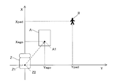
図2に示すように、設定部130は、第1推定部110により推定された第1推定位置A1に関するパラメータに基づいて2次元領域Aを設定する。図2~図5では、上記のiが任意の数字のときの状態が示されている。
第1推定位置A1に関するパラメータは、車軸Z1の中心位置Z2に対応する位置座標のX成分およびY成分である。
設定部130は、当該中心位置Z2に対応する位置座標と、車両Zの幅および長さとを基準に2次元領域Aを設定する。
2次元領域Aは、車両の長さ方向が縦軸と平行であり、幅方向が横軸と平行である矩形状の領域として設定される。
図3に示すように、設定部130は、2次元領域A内の1以上の代表位置Tを第1位置情報として設定する。図2では、2次元領域Aに沿う位置や、車軸Z1の中心位置Z2と一致する位置を含む計15個の代表位置を例示する。
また、図4に示すように、設定部130は、第2推定部120により推定された物体Bの第2推定位置に関するパラメータに基づいて、物体Bの位置座標を2次元領域Aと整合するように補正する。設定部130は、補正後の物体B1の位置座標を第2位置情報とする。
2次元領域Aは、各辺が縦軸または横軸と平行になるように設定されるが、車両Zが旋回するような場合、2点鎖線A2で示すように、第1推定部110により推定されたθegoだけ、車両Zは、縦軸に対して傾斜することとなる。
そのため、設定部130は、式(4)によって推定された物体Bの位置座標を2次元領域Aに整合するように補正する。第1推定位置A1での車両Zは、本来2次元領域Aに対して傾斜している。つまり、2次元領域Aは、第1推定位置A1における車両Zに対して第1推定位置A1を中心に、+θego回転した状態である。そこで、2次元領域Aと整合するように、物体Bを、第1推定位置A1を中心に-θego回転させる。このようにすることで、車両Zと、補正後の物体B1との位置関係を正確なものとすることができる。
第1分散算出部140は、設定された各第1位置情報に係る第1分散値をそれぞれ算出する。具体的には、第1分散算出部140は、例えば式(6)のように、カルマンフィルタの共分散行列を用いることで、第1分散値Pegoを算出する。

第2分散算出部150は、設定された第2位置情報に係る第2分散値を算出する。具体的には、第2分散算出部150は、例えば式(7)のように、カルマンフィルタの共分散行列を用いることで、第2分散値Ppedを算出する。

第1分散算出部140は、時刻k+1~k+iまでのi個の第1分散値を、複数の代表位置T毎に算出する。また、第2分散算出部150は、時刻k+1~k+iまでのi個の第2分散値を算出する。
確率算出部160は、2次元領域A、第1位置情報、第2位置情報、第1分散値および第2分散値を用いて、車両と物体とが衝突する確率(以下、「衝突確率」という)を算出する。確率算出部160は、2次元領域Aにおける各代表位置Tの全ての衝突確率を算出する。
具体的に、確率算出部160は、式(8)~(12)のように、2次元の正規分布に基づいて衝突確率を算出する。なお、式(11)におけるパラメータは、式(6)および式(7)で算出された値である。また、式(12)におけるパラメータは、式(2)、式(5)等で算出された値である。また、式(8)~(12)は、時刻k+iでの、衝突確率の算出式である。

Area:2次元領域Aの範囲内
r:2次元領域Aの範囲内における位置関数(X成分およびY成分の関数)
D(r):確率分布




Yrot:Ypedを補正した後の物体B1の位置座標のY成分
例えば、式(12)で算出される2次元領域Aの任意の代表位置T(第1位置情報)と、物体B1の位置(第2位置情報)との相対位置ベクトルΔrに基づいて、物体B1が2次元領域A内に位置するとする。なお、図5では、2次元領域Aの右上端の代表位置Tと物体B1との相対位置ベクトルΔrのみを例示している。また、図5では、図面の見やすさを考慮して、物体B1が2次元領域Aの外側にいる例が示されている。
物体B1が2次元領域A内に位置する場合、車両Zと、物体とが衝突する可能性が高くなる。それに対して、相対位置ベクトルΔrに基づいて、物体B1が2次元領域A内に位置しない場合、車両Zと、物体とが衝突しない可能性が高くなる。
しかし、上記のように衝突可能性を判定する場合、不確定の度合いが高い。そのため、本実施の形態では、式(9)で示される確率分布D(r)を式(8)において、2次元領域A内でX成分、Y成分による積分を行うことで、2次元領域A内に物体B1が浸入している確率、つまり、衝突確率を算出することができる。
すなわち、本実施の形態では、車両Zが将来到達していると推定されるX成分およびY成分で構成される2次元領域A内に物体が浸入する確率を算出するので、衝突確率を正確に算出することができる。
確率算出部160は、基準位置に位置する時刻より後の第1時刻から第2時刻までの間に移動する各2次元領域Aにおける各衝突確率を算出する。第1推定位置は、時刻毎にそれぞれ推定され、2次元領域Aがそれぞれ設定される。そのため、確率算出部160は、第1時刻から第2時刻までの間における各時刻における各2次元領域Aにおける全ての代表位置Tでの衝突確率をそれぞれ算出することとなる。
具体的には、確率算出部160は、各時刻において、15個の代表位置Tにそれぞれ対応する15個の衝突確率を算出する。確率算出部160は、算出した各代表位置Tにおける全ての衝突確率のうち、最大値となる第1衝突確率を、時刻毎に抽出する。
第1衝突確率の抽出結果は、例えば、図6に示すようなグラフとなる。当該グラフは、時刻k+1(第1時刻)から時刻k+m(m:iよりも小さい値)まで、第1衝突確率が徐々に上昇した後、時刻k+mをピークとして、それ以降の時刻k+i(第2時刻)において第1衝突確率が減少するように変動する例を示している。
そして、確率算出部160は、第1時刻から第2時刻までの間の各第1衝突確率の中から、最大値となる第2衝突確率を衝突確率とする。図6に示す例では、確率算出部160は、時刻k+mにおける第1衝突確率が第2衝突確率である。
これにより、衝突確率の算出を行う期間において最大値となる衝突確率を容易に抽出することができる。
確率算出部160は、第2衝突確率に基づいて警報指令を出力する。具体的には、確率算出部160は、第2衝突確率が所定閾値以上である場合、車両と物体との衝突確率が高い旨を乗員に知らせるための警報指令を報知部30に出力する。
このようにすることで、衝突確率の算出を行う期間において最大値となる衝突確率に基づいた報知処理を容易に行うことができる。
以上のように構成された衝突確率算出装置100における衝突確率算出制御の動作例について説明する。図7は、衝突確率算出装置100における衝突確率算出制御の動作例を示すフローチャートである。図7における処理は、例えば、車両が走行を開始した際に適宜実行される。
図7に示すように、衝突確率算出装置100は、車両および物体の位置座標を推定する(ステップS101)。次に、衝突確率算出装置100は、推定された車両の位置情報に基づいて2次元領域Aを設定して(ステップS102)、代表位置を設定する(ステップS103)。
次に、衝突確率算出装置100は、設定した各代表位置に基づく第1分散値および物体の位置座標に基づく第2分散値を算出する(ステップS104)。
ステップS104の後、衝突確率算出装置100は、第1位置情報、第2位置情報、第1分散値、および、第2分散値を用いて衝突確率を算出する(ステップS105)。
そして、衝突確率算出装置100は、算出した衝突確率が所定閾値以上であるか否かについて判定する(ステップS106)。判定の結果、衝突確率が所定閾値未満である場合(ステップS106、NO)、本制御は終了する。
一方、衝突確率が所定閾値以上である場合(ステップS106、YES)、衝突確率算出装置100は、警報指令を出力する(ステップS107)。ステップS107の後、本制御は終了する。
以上のように構成された本実施の形態によれば、2次元領域A、第1位置情報、第2位置情報、第1分散値および第2分散値を用いて衝突確率を算出するので、車両と物体との位置関係を考慮した衝突確率を算出することができる。
具体的には、車両Zが将来移動すると推定される2次元領域Aと、物体が将来移動すると推定される位置とを照らし合わせて、X成分およびY成分で車両と物体との相対位置に基づく関数を積分することで衝突確率を算出する。そのため、車両と物体との衝突確率を正確に算出することができる。
また、互いに異なる方向成分であるX成分およびY成分で構成される2次元領域A内へ物体が浸入する確率を、2次元の正規分布に基づいて算出するので、2次元領域A内における衝突確率を正確に算出することができる。
また、2次元領域Aを用いることで、車両の長さ方向や幅方向を考慮した衝突確率を算出することができるので、例えば、車両の進行方向のみの情報に基づく構成と比較して、衝突確率の精度を大幅に向上させることができる。
また、2次元領域A内で設定された全ての代表位置Tに基づく衝突確率を算出するので、車両と物体とが衝突する可能性が高い位置に基づく衝突確率を抽出することができる。その結果、車両と物体との衝突確率を正確に算出することができる。
また、車両の車軸を基準に2次元領域Aが設定される。つまり、車両の旋回中心を基準にして第1推定位置が推定される。そのため、物体の位置を2次元領域Aに整合させる際に、物体の位置を、第1推定部110により推定されるθego回転させるだけで良くなる。その結果、車両と物体との位置関係を正確にしやすくすることができ、ひいては車両と物体との衝突確率を正確に算出することができる。
また、車両が第1時刻から第2時刻までの間に移動する各第1位置における各衝突確率を算出するので、その中から最大値となる衝突確率を抽出することができる。その結果、将来的に衝突確率が高くなることを、早期に把握することができるので、安全性を大幅に向上させることができる。
なお、上記実施の形態では、代表位置が、2次元領域A内で3行、5列の計15個、並んでいたが、本開示はこれに限定されず、2次元領域A内に1以上の数、設けられていれば良い。ただし、物体B1が2次元領域A内に完全に入った状態における衝突確率を抽出しやすくなる観点から、設定部130は、代表位置Tを少なくとも2次元領域Aの内部に設けることが好ましい。
また、例えば、設定部130は、2次元領域A内における車軸の前方領域の代表位置の数を、2次元領域A内における車軸の後方領域の代表位置よりも多くするようにしても良い。
このようにすることで、物体と衝突する可能性が高い車両の前部を重視して衝突確率を算出することができる。
また、設定部130は、第1位置情報に基づいて、2次元領域Aにおける車両の移動方向とは反対側の端部を代表位置の設定から除外するようにしても良い。つまり、車両が右折する際には、2次元領域Aにおける左端部側が代表位置の設定から除外される。
車両が旋回する際には、車両の内回りとなる内側部分が外回りとなる外側部分よりも先に移動していくため、内側部分と物体とが衝突する可能性が高くなると考えられる。そのため、2次元領域Aの内側部分を重視して衝突確率を算出することで、衝突可能性が高い代表位置に基づく衝突確率を抽出しやすくすることができる。
また、上記実施の形態では、式(8)~(12)に基づいて衝突確率を算出していたが、本開示はこれに限定されず、他の方法に基づいて衝突確率を算出しても良い。
また、上記実施の形態では、カルマンフィルタにより各パラメータを算出していたが、本開示はこれに限定されず、他の方法により各パラメータを算出しても良い。
その他、上記実施の形態は、何れも本開示を実施するにあたっての具体化の一例を示したものに過ぎず、これらによって本開示の技術的範囲が限定的に解釈されてはならないものである。すなわち、本開示はその要旨、またはその主要な特徴から逸脱することなく、様々な形で実施することができる。
本出願は、2019年3月18日付で出願された日本特許出願(特願2019-049599)に基づくものであり、その内容は、ここに参照として全て取り込まれる。
本開示の衝突確率算出装置は、車両と物体との衝突確率を正確に算出することが可能な衝突確率算出装置、衝突確率算出システムおよび衝突確率算出方法として有用である。
1 衝突確率算出システム
10 第1検出部
11 車速センサ
12 ヨーレートセンサ
20 第2検出部
21 カメラ
22 レーダ
30 報知部
100 衝突確率算出装置
110 第1推定部
120 第2推定部
130 設定部
140 第1分散算出部
150 第2分散算出部
160 確率算出部
10 第1検出部
11 車速センサ
12 ヨーレートセンサ
20 第2検出部
21 カメラ
22 レーダ
30 報知部
100 衝突確率算出装置
110 第1推定部
120 第2推定部
130 設定部
140 第1分散算出部
150 第2分散算出部
160 確率算出部
Claims (12)
- 第1方向と、前記第1方向と異なる第2方向との各方向成分で構成され、車両が基準位置から将来到達すると推定された第1推定位置を含む2次元領域を設定する設定部と、
前記2次元領域の第1位置情報における第1分散値を算出する第1分散算出部と、
前記車両が前記第1推定位置に到達するタイミングで物体が将来到達すると推定された第2推定位置の第2位置情報における第2分散値を算出する第2分散算出部と、
前記2次元領域、前記第1位置情報、前記第2位置情報、前記第1分散値および前記第2分散値を用いて、前記車両と前記物体とが衝突する確率を算出する確率算出部と、
を備える衝突確率算出装置。 - 前記確率算出部は、2次元の正規分布に基づいて、前記確率を算出する、
請求項1に記載の衝突確率算出装置。 - 前記設定部は、前記2次元領域における1以上の代表位置を、前記第1位置情報として設定し、
前記第1分散算出部は、前記1以上の代表位置に係る分散値を前記第1分散値として算出し、
前記確率算出部は、前記1以上の代表位置に係る前記確率をそれぞれ算出する、
請求項1に記載の衝突確率算出装置。 - 前記第1推定位置は、前記車両の車軸の中心位置であり、
前記設定部は、前記中心位置と、前記車両の幅および長さとを基準に前記2次元領域を設定する、
請求項3に記載の衝突確率算出装置。 - 前記設定部は、前記2次元領域内における前記車軸の前方領域の代表位置の数を、前記2次元領域内における前記車軸の後方領域の代表位置の数よりも多くする、
請求項4に記載の衝突確率算出装置。 - 前記設定部は、前記代表位置を少なくとも前記2次元領域の内部に設定する、
請求項3に記載の衝突確率算出装置。 - 前記設定部は、前記第1位置情報に基づいて、前記2次元領域における前記車両の移動方向とは反対側の端部を前記代表位置の設定から除外する、
請求項3に記載の衝突確率算出装置。 - 前記確率算出部は、
前記車両が、前記基準位置に位置する時刻より後の第1時刻から第2時刻までの間に移動する各2次元領域における前記確率をそれぞれ算出し、
算出した全ての前記確率のうち、最大値となる確率に基づいて警報指令を出力する、
請求項1に記載の衝突確率算出装置。 - 前記基準位置における前記車両の速度情報およびヨーレート情報に基づいて前記第1推定位置に関するパラメータを推定する第1推定部と、
前記車両が前記基準位置に位置する際の前記物体の位置情報および速度情報に基づいて前記第2推定位置に関するパラメータを推定する第2推定部と、
を備える、
請求項1に記載の衝突確率算出装置。 - 前記設定部は、前記第2推定部により推定されたパラメータに基づく前記物体の位置情報を前記2次元領域と整合するように補正して前記第2位置情報とする、
請求項9に記載の衝突確率算出装置。 - 前記車両の前記基準位置に関するパラメータを検出する第1検出部と、
前記車両が前記基準位置に位置する際の前記物体の位置に関するパラメータを検出する第2検出部と、
請求項1に記載の衝突確率算出装置と、
を備える衝突確率算出システム。 - 第1方向と、前記第1方向と異なる第2方向との各方向成分で構成され、車両が基準位置から将来到達すると推定された第1推定位置を含む2次元領域を設定し、
前記2次元領域の第1位置情報における第1分散値を算出し、
前記車両が前記第1推定位置に到達するタイミングで物体が将来到達すると推定された第2推定位置の第2位置情報における第2分散値を算出し、
前記2次元領域、前記第1位置情報、前記第2位置情報、前記第1分散値および前記第2分散値を用いて、前記車両と前記物体とが衝突する確率を算出する衝突確率算出方法。
Priority Applications (3)
| Application Number | Priority Date | Filing Date | Title |
|---|---|---|---|
| CN202080020887.4A CN113574582B (zh) | 2019-03-18 | 2020-03-16 | 碰撞概率计算装置、计算系统以及计算方法 |
| US17/439,956 US12115980B2 (en) | 2019-03-18 | 2020-03-16 | Collision probability calculation device, collision probability calculation system and collision probability calculation method |
| DE112020001347.2T DE112020001347T5 (de) | 2019-03-18 | 2020-03-16 | Kollisionswahrscheinlichkeitsberechnungsvorrichtung, kollisionswahrscheinlichkeitsberechnungssystem und kollisionswahrscheinlichkeitsberechnungsverfahren |
Applications Claiming Priority (2)
| Application Number | Priority Date | Filing Date | Title |
|---|---|---|---|
| JP2019049599A JP2020154384A (ja) | 2019-03-18 | 2019-03-18 | 衝突確率算出装置、衝突確率算出システムおよび衝突確率算出方法 |
| JP2019-049599 | 2019-03-18 |
Publications (1)
| Publication Number | Publication Date |
|---|---|
| WO2020189624A1 true WO2020189624A1 (ja) | 2020-09-24 |
Family
ID=72520116
Family Applications (1)
| Application Number | Title | Priority Date | Filing Date |
|---|---|---|---|
| PCT/JP2020/011472 Ceased WO2020189624A1 (ja) | 2019-03-18 | 2020-03-16 | 衝突確率算出装置、衝突確率算出システムおよび衝突確率算出方法 |
Country Status (5)
| Country | Link |
|---|---|
| US (1) | US12115980B2 (ja) |
| JP (1) | JP2020154384A (ja) |
| CN (1) | CN113574582B (ja) |
| DE (1) | DE112020001347T5 (ja) |
| WO (1) | WO2020189624A1 (ja) |
Families Citing this family (4)
| Publication number | Priority date | Publication date | Assignee | Title |
|---|---|---|---|---|
| US11912268B2 (en) | 2021-04-30 | 2024-02-27 | Zoox, Inc. | Velocity regression safety system |
| EP4112411B1 (en) * | 2021-07-01 | 2024-03-27 | Zenseact AB | Estimation of accident intensity for vehicles |
| JP7472866B2 (ja) * | 2021-07-06 | 2024-04-23 | トヨタ自動車株式会社 | 車両用操舵ガイドトルク制御装置 |
| CN115140034B (zh) * | 2022-06-27 | 2026-01-13 | 阿里巴巴达摩院(杭州)科技有限公司 | 碰撞风险检测方法、装置及设备 |
Citations (3)
| Publication number | Priority date | Publication date | Assignee | Title |
|---|---|---|---|---|
| JP2012118741A (ja) * | 2010-11-30 | 2012-06-21 | Toyota Central R&D Labs Inc | 可動物の目標状態決定装置及びプログラム |
| JP2018045426A (ja) * | 2016-09-14 | 2018-03-22 | いすゞ自動車株式会社 | 衝突確率推定装置 |
| JP2018151816A (ja) * | 2017-03-13 | 2018-09-27 | トヨタ自動車株式会社 | 衝突回避制御装置 |
Family Cites Families (14)
| Publication number | Priority date | Publication date | Assignee | Title |
|---|---|---|---|---|
| IL100175A (en) * | 1991-11-27 | 1994-11-11 | State Of Isreal Ministry Of De | Vehicle collision warning device |
| US7864032B2 (en) | 2005-10-06 | 2011-01-04 | Fuji Jukogyo Kabushiki Kaisha | Collision determination device and vehicle behavior control device |
| JP2010038706A (ja) | 2008-08-05 | 2010-02-18 | Fujitsu Ten Ltd | 信号処理装置、及びレーダ装置 |
| EP2306433A1 (en) * | 2009-10-05 | 2011-04-06 | Nederlandse Organisatie voor toegepast -natuurwetenschappelijk onderzoek TNO | Collision avoidance system and method for a road vehicle and respective computer program product |
| JP5267517B2 (ja) * | 2010-07-14 | 2013-08-21 | 株式会社デンソー | 車両位置推定装置、および車両位置推定プログラム |
| JP5475138B2 (ja) * | 2010-09-08 | 2014-04-16 | トヨタ自動車株式会社 | 移動物予測装置、仮想可動物予測装置、プログラム、移動物予測方法、及び仮想可動物予測方法 |
| JP5690688B2 (ja) | 2011-09-15 | 2015-03-25 | クラリオン株式会社 | 外界認識方法,装置,および車両システム |
| EP3296762A4 (en) | 2015-05-11 | 2018-05-16 | Panasonic Intellectual Property Management Co., Ltd. | Monitored area setting device and monitored area setting method |
| MX364578B (es) * | 2015-08-28 | 2019-05-02 | Nissan Motor | Dispositivo de estimacion de posicion de vehiculo, metodo de estimacion de posicion de vehiculo. |
| JP6504078B2 (ja) * | 2016-02-24 | 2019-04-24 | 株式会社デンソー | 衝突予測装置 |
| JP2018091785A (ja) | 2016-12-06 | 2018-06-14 | 株式会社デンソーテン | レーダ装置および物標検知方法 |
| KR101977458B1 (ko) * | 2017-03-06 | 2019-05-10 | 지엠 글로벌 테크놀러지 오퍼레이션스 엘엘씨 | 레이더 센서와 upa 센서를 이용하는 충돌 예측 알고리즘 |
| US11231281B2 (en) * | 2017-06-16 | 2022-01-25 | Honda Motor Co., Ltd. | Information-processing device, information-processing method, and program |
| JP6984254B2 (ja) | 2017-09-08 | 2021-12-17 | ヤマハ株式会社 | カラオケユニット |
-
2019
- 2019-03-18 JP JP2019049599A patent/JP2020154384A/ja active Pending
-
2020
- 2020-03-16 CN CN202080020887.4A patent/CN113574582B/zh active Active
- 2020-03-16 US US17/439,956 patent/US12115980B2/en active Active
- 2020-03-16 DE DE112020001347.2T patent/DE112020001347T5/de active Pending
- 2020-03-16 WO PCT/JP2020/011472 patent/WO2020189624A1/ja not_active Ceased
Patent Citations (3)
| Publication number | Priority date | Publication date | Assignee | Title |
|---|---|---|---|---|
| JP2012118741A (ja) * | 2010-11-30 | 2012-06-21 | Toyota Central R&D Labs Inc | 可動物の目標状態決定装置及びプログラム |
| JP2018045426A (ja) * | 2016-09-14 | 2018-03-22 | いすゞ自動車株式会社 | 衝突確率推定装置 |
| JP2018151816A (ja) * | 2017-03-13 | 2018-09-27 | トヨタ自動車株式会社 | 衝突回避制御装置 |
Also Published As
| Publication number | Publication date |
|---|---|
| CN113574582B (zh) | 2022-12-27 |
| US20220185270A1 (en) | 2022-06-16 |
| US12115980B2 (en) | 2024-10-15 |
| CN113574582A (zh) | 2021-10-29 |
| DE112020001347T5 (de) | 2022-01-05 |
| JP2020154384A (ja) | 2020-09-24 |
Similar Documents
| Publication | Publication Date | Title |
|---|---|---|
| CN113574582B (zh) | 碰撞概率计算装置、计算系统以及计算方法 | |
| CN105774805B (zh) | 用于估算车道的系统及其方法 | |
| CN104118432A (zh) | 车用碰撞缓解设备 | |
| US10789491B2 (en) | Traffic light recognition device and traffic light recognition method | |
| US10896612B2 (en) | Lane change assistance device and lane change assistance method | |
| US10635911B2 (en) | Apparatus and method for recognizing travel lane | |
| JP6601352B2 (ja) | 車両姿勢推定装置 | |
| EP2824425A1 (en) | Moving-object position/attitude estimation apparatus and method for estimating position/attitude of moving object | |
| US10323947B2 (en) | Travel control method and travel control apparatus | |
| US9988082B2 (en) | Traveling path estimation apparatus | |
| JP6020729B2 (ja) | 車両位置姿勢角推定装置及び車両位置姿勢角推定方法 | |
| CN104176053A (zh) | 碰撞缓解设备 | |
| JP2018036067A (ja) | 自車位置認識装置 | |
| BR112018003728B1 (pt) | Dispositivo de estimativa de posição de veículo e método de estimativa de posição de veículo | |
| KR102304851B1 (ko) | Ecu, 상기 ecu를 포함하는 무인 자율 주행 차량, 및 이의 주변 차량 인지 방법 | |
| JP2017043279A (ja) | 車両制御装置、及び走路信頼度判定方法 | |
| JP4997778B2 (ja) | 乗員保護装置 | |
| JP6044084B2 (ja) | 移動物体位置姿勢推定装置及び方法 | |
| JP6649047B2 (ja) | 車両走行制御装置 | |
| JP6645936B2 (ja) | 状態推定装置 | |
| JP6243319B2 (ja) | 逸脱判定装置 | |
| JP6901870B2 (ja) | 位置推定装置、制御方法、及びプログラム | |
| JP7649981B2 (ja) | 情報処理方法、プログラム及び移動体 | |
| EP3971525B1 (en) | Self-position correction method and self-position correction device | |
| JP5472137B2 (ja) | 境界検出装置、および境界検出プログラム |
Legal Events
| Date | Code | Title | Description |
|---|---|---|---|
| 121 | Ep: the epo has been informed by wipo that ep was designated in this application |
Ref document number: 20774536 Country of ref document: EP Kind code of ref document: A1 |
|
| 122 | Ep: pct application non-entry in european phase |
Ref document number: 20774536 Country of ref document: EP Kind code of ref document: A1 |