WO2020189611A1 - アウトレットバルブ - Google Patents
アウトレットバルブ Download PDFInfo
- Publication number
- WO2020189611A1 WO2020189611A1 PCT/JP2020/011374 JP2020011374W WO2020189611A1 WO 2020189611 A1 WO2020189611 A1 WO 2020189611A1 JP 2020011374 W JP2020011374 W JP 2020011374W WO 2020189611 A1 WO2020189611 A1 WO 2020189611A1
- Authority
- WO
- WIPO (PCT)
- Prior art keywords
- valve opening
- width direction
- vehicle width
- valve
- cab
- Prior art date
- Legal status (The legal status is an assumption and is not a legal conclusion. Google has not performed a legal analysis and makes no representation as to the accuracy of the status listed.)
- Ceased
Links
Images




Classifications
-
- B—PERFORMING OPERATIONS; TRANSPORTING
- B60—VEHICLES IN GENERAL
- B60H—ARRANGEMENTS OF HEATING, COOLING, VENTILATING OR OTHER AIR-TREATING DEVICES SPECIALLY ADAPTED FOR PASSENGER OR GOODS SPACES OF VEHICLES
- B60H1/00—Heating, cooling or ventilating devices
- B60H1/24—Ventilating devices where the heating or cooling is irrelevant
- B60H1/26—Ventilating openings in vehicle exterior; Ducts for conveying ventilating air
-
- B—PERFORMING OPERATIONS; TRANSPORTING
- B62—LAND VEHICLES FOR TRAVELLING OTHERWISE THAN ON RAILS
- B62D—MOTOR VEHICLES; TRAILERS
- B62D33/00—Superstructures for load-carrying vehicles
- B62D33/06—Drivers' cabs
Definitions
- the present disclosure relates to an outlet valve provided on the rear surface of the cab facing the front surface of the loading platform, which allows the outflow of air from the inside of the vehicle to the outside of the vehicle and prevents the inflow of air from the outside of the vehicle to the inside of the vehicle.
- Patent Document 1 describes a vehicle ventilation device provided with a frame body and a seat-shaped valve body.
- the frame body has a tubular portion that forms an exhaust port that exhausts the air inside the vehicle to the outside of the vehicle, and a flange portion that extends the outer peripheral edge of the tubular portion outward and is fixed to the outside of the vehicle body panel via a seal member. And are integrally molded.
- the seat-shaped valve body is a rubber seat plate, which is hung from the upper surface of the tubular portion to cover the exhaust port, and is displaced to the outside of the vehicle in response to an increase in the pressure inside the vehicle to open the exhaust port.
- the purpose of this disclosure is to suppress the ingress of water into the vehicle due to water exposure from the vehicle width direction.
- the first aspect of the present disclosure is an outlet valve provided on the rear surface of the cab facing the front surface of the loading platform, which includes a valve opening, a baffle, and a water-impervious surface.
- the valve opening communicates inside the cab and outside the cab.
- the baffle is supported by the upper edge of the valve opening and hangs so as to close the valve opening.
- the baffle can prevent the valve opening from being displaced forward from the closing position that closes the valve opening, and can open the valve opening by being pushed from the front and displaced backward at the closing position.
- the impermeable surface is arranged on the other side in the vehicle width direction from the rear end edge on one side in the vehicle width direction of the valve opening, stands up at the intersection with the vehicle width direction, and has the valve on the one side edge in the vehicle width direction on the front of the loading platform. It extends continuously from the rear end edge of the valve opening on the other side of the vehicle width direction to the extension of the straight line connecting the rear end edge on one side in the vehicle width direction of the opening.
- the second aspect of the present disclosure is the outlet valve of the first aspect, which is provided with a drainage bottom surface below the impermeable surface.
- the water flowing down the impermeable surface can be discharged to the outside of the cab below the rear by the bottom surface for drainage.
- outlet valve of the present disclosure it is possible to suppress the ingress of water into the vehicle when it is inundated from the vehicle width direction.
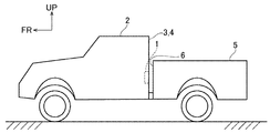
- FIG. 1 is a perspective view of a vehicle to which an outlet valve according to an embodiment of the present disclosure is attached.
- FIG. 2 is a side view of the vehicle of FIG.
- FIG. 3 is a front view of the outlet valve of FIG. 1 as viewed from the rear.
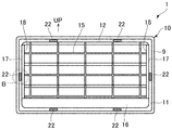
- FIG. 4 is a rear view of the outlet valve of FIG. 3 as viewed from the front.
- FIG. 5 is a sectional view taken along line VV of FIG.
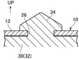
- FIG. 6A is a cross-sectional view of portion A of FIG. 5 as viewed from the rear.
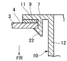
- FIG. 6B is a cross-sectional view of the portion B of FIG. 4 in a state where the outlet valve is attached to the cab back panel, as viewed from above.
- FIG. 5 is a plan view schematically showing the positional relationship between the impermeable surface of FIG. 5 and the edge of the front surface of the loading platform on one side in the vehicle width direction.
- FR indicates the front of the vehicle
- UP in the figure indicates the upper part of the vehicle.
- front-rear direction in the following description means the front-rear direction of the vehicle
- left-right direction means the left-right direction in a state of facing the front of the vehicle.
- vehicle to which the outlet valve 1 can be applied is not limited to the pickup truck.
- the rear surface (cab rear surface) 4 of the cab back panel 3 that stands up along the vehicle width direction at the rear end of the cab 2 stands up along the vehicle width direction at the front end of the loading platform 5.
- the front surface 6 of the loading platform faces from the rear.
- the outlet valve 1 is attached to the rear surface 4 of the cab and faces the front surface 6 of the loading platform from the front. In the following, the outlet valve 1 in a state (posture) attached to the rear surface 4 of the cab will be described.
- the outlet valve 1 is roughly composed of a valve body 10 and a plurality of baffles 30 (31, 32, 33), and the valve body 10 includes a frame body portion 11 and a duct portion. 12, the upper and lower partition plate portions 13 and 14, the grid-like stopper portion 15, and the water receiving portion 16 are integrally provided.
- the frame body portion 11 has a rectangular frame shape, and the duct portion 12 extends forward from the inner peripheral edge of the frame body portion 11 in a rectangular tubular shape.
- the upper and lower partition plate portions 13 and 14 face each other vertically on the inside of the duct portion 12 and extend in the vehicle width direction to connect the inner surfaces of the left and right side walls 17 of the duct portion 12.
- the frame body portion 11 and the upper and lower partition plate portions 13, 14 form a section of valve openings 19, 20, 21 having substantially the same shape arranged in three upper and lower stages.
- the valve openings 19, 20, and 21 have a rectangular horizontal shape in which the width in the vehicle width direction is longer than the vertical width in the vertical direction, and are between the inside (inside the vehicle) and the outside (the rear surface 4 of the cab and the front surface 6 of the loading platform 6) of the cab 2. It communicates with the space outside the vehicle).
- the stopper portion 15 has an upper region arranged in front of the valve opening 19 in the upper stage, a middle region arranged in front of the valve opening 20 in the middle stage, and a lower region arranged in front of the valve opening 21 in the lower stage.
- Each region of the stopper portion 15 has a rearward and downward inclination (see FIG. 5).
- the peripheral edge of each region of the stopper portion 15 is fixed to the duct portion 12 and the partition plate portions 13 and 14, to reinforce the duct portion 12 and the partition plate portions 13 and 14, and to move forward from the closed position as described later. Prevents the baffle 30 from tilting.
- the cab back panel 3 is formed with a rectangular valve mounting hole 7 (see FIGS. 5 and 6B) that is slightly larger than the outer shape of the duct portion 12 and smaller than the outer shape of the frame body portion 11.
- the outlet valve 1 is fixed to the cab back panel 3 (rear surface 4 of the cab).
- a total of six locking projections 22 of two pairs of upper and lower and one pair of left and right are projected forward from the front surface of the upper, lower, left and right frame portions 11 of the duct portion 12 (see FIG.
- the outlet valve 1 is mounted on the rear surface of the cab. Fix to 4.
- a sealing material 9 is interposed between the front surface of the frame body 11 and the cab rear surface 4, and the sealing material 9 is sealed between the frame body 11 and the cab rear surface 4.
- the outlet valve 1 may be fixed to the rear surface 4 of the cab by another method (for example, fastening with a bolt).
- the water receiving portion 16 has a rectangular box shape with an open upper part.
- the bottom plate 23 and the left and right side plates 24 of the water receiving portion 16 continuously extend forward from the duct portion 12, and the lower end portion of the duct portion 12 constitutes the rear end portion of the water receiving portion 16.
- the upper surface of the bottom plate 23 constitutes a drainage bottom surface 25, and the drainage bottom surface 25 is arranged below the partition plate portions 13, 14, the stopper portions 15, and the impermeable surface 18 described later.
- the drainage bottom surface 25 is inclined rearward and downward so that water can easily flow toward the lower valve opening 21.
- the baffle 30 is a thin plate-shaped elastic body formed of a flexible material such as rubber.
- the upper valve opening 19 has an upper baffle 31 and a middle valve opening.
- a baffle 32 in the middle stage is provided in the 20th stage, and a baffle 33 in the lower stage is provided in the valve opening 21 in the lower stage.
- the width of the upper and middle baffles 31 and 32 in the vehicle width direction is substantially equal to the width of the lower baffle 33, and the vertical width of the upper and middle baffles 31 and 32 is the same as the height of the lower baffle 33. Approximately equal.
- Each baffle 30 is supported by the upper edges of the valve openings 19, 20 and 21 and hangs diagonally downward so as to close the upper valve opening 19, the middle valve opening 20 and the lower valve opening 21, respectively.
- the forward displacement (tilt) from the closing position that closes the valve openings 19, 20, 21 is prevented, and the valve openings 19, 20, 21 are pushed from the front and displaced backward at the closing position that closes the valve openings 19, 20, 21. Opens the valve openings 19, 20 and 21.
- a valve is provided with a locking protrusion 34 having an arrowhead shape in a plan view that integrally protrudes from the upper edge of each baffle 30 (in the example of FIG. 6A, the middle baffle 32).
- baffle locking hole 26 formed in the upper edge portion (upper partition plate portion 13 in the example of FIG. 6A) of the openings 19, 20 and 21, and the locking protrusion 34 is inserted into the baffle locking hole 26.
- the baffle 30 is supported by the valve body 10 and hangs down.
- Four baffle locking holes 26 are arranged at substantially equal intervals on each stage, and each baffle 30 is supported at four locations.
- the method of supporting the upper end portion of the baffle 30 is not limited to the above, and other methods (for example, fastening with a bolt, fixing with an adhesive, etc.) may be used.
- Each baffle 30 hangs diagonally downward along the rear surface of the stopper portion 15 in a normal state where no external force is applied to close the valve openings 19, 20, 21 (closed position), and the stopper portion 15 is in the closed position. Prevents the baffle 30 from tilting forward. That is, the baffle 30 allows the flow of air from the inside of the cab 2 to the outside of the cab 2 and prevents the movement of air from the outside of the cab 2 into the cab 2.
- the left and right side walls 17 of the duct portion 12 are rearward from the baffle 30 and the stopper portion 15 from the left and right peripheral edges of the frame portion 11 (the range from the upper end of the upper valve opening 19 to the lower end of the lower valve opening 21). It extends continuously, and the lower end of the side wall 17 is continuous with the upper end of the side plate 24 of the water receiving portion 16.
- the inner surface of the side wall 17 is arranged on the other side in the vehicle width direction from the rear end edge on one side in the vehicle width direction of the valve openings 19, 20, 21 and stands up substantially vertically at the intersection with the vehicle width direction.
- the other side of the valve openings 19, 20, 21 in the vehicle width direction constitutes an impermeable surface 18 that continuously extends from the trailing edge.
- the impermeable surface 18 of the side wall 17 on the left side is on the left side of the rear end edge 40 on the right side (one side in the vehicle width direction) of the valve openings 19, 20, 21 as shown in FIG.
- the upper part of the water receiving portion 16 and the space between the left and right side walls 17 are opened upward and forward in order to ensure air permeability.
- the rapid rise in air pressure inside the cab 2 when the door of the cab 2 (not shown) is closed is suppressed by the outflow of air from the outlet valve 1. Therefore, the door can be closed smoothly.
- Water that has passed between the rear surface 4 of the cab and the front surface 6 of the loading platform diagonally forward from the outside in the vehicle width direction and has entered the outlet valve 1 from the valve openings 19, 20, 21 due to the curling of the baffle 30 is an impermeable surface. Since it hits 18 and flows down, it is possible to suppress the intrusion of water into the cab 2 (inside the vehicle).
- the water flowing down the impermeable surface 18 can be received by the drainage bottom surface 25 and discharged from the lower valve opening 21 to the outside of the rear lower cab 2.
- valve openings 19, 20, and 21 are arranged in three upper and lower stages, but the valve openings may be one stage or a plurality of stages other than the three stages.
- the shape of the valve openings may be different between the stages.
- the case where the side wall 17 of the duct portion 12 is extended forward to form the impermeable surface 18 has been described.
- a wall portion extending forward from a portion of the valve body 10 other than the duct portion 12 is provided, and the wall portion is provided.
- the inner surface may be a water-impervious surface, or the wall portion may be formed separately and attached to the valve body 10.
- the position of the outlet valve 1 on the rear surface 4 of the cab in the vehicle width direction is arbitrary, the effect of suppressing inundation by the impermeable surface 18 increases as the outlet valve 1 is arranged unevenly on one of the left and right sides.
- the outlet valve of the present disclosure can be widely applied to a vehicle in which the rear surface of the cab and the front surface of the loading platform face each other.
- Outlet valve 2 Cab 3: Cab back panel 4: Cab rear surface 5: Loading platform 6: Loading platform front 7: Valve mounting hole 10: Valve body 11: Frame body portion 12: Duct portion 13, 14: Partition plate portion 15: Stopper 16: Water receiving part 17: Side wall of duct part 18: Impermeable surface 19, 20, 21: Valve opening 22: Locking protrusion 23: Bottom plate of water receiving part 24: Side plate of water receiving part 25: Bottom surface for drainage 26 : Baffle locking holes 30, 31, 32, 33: Baffle 34: Locking protrusion
Landscapes
- Engineering & Computer Science (AREA)
- Mechanical Engineering (AREA)
- Physics & Mathematics (AREA)
- Thermal Sciences (AREA)
- Chemical & Material Sciences (AREA)
- Combustion & Propulsion (AREA)
- Transportation (AREA)
- Air-Conditioning For Vehicles (AREA)
- Body Structure For Vehicles (AREA)
Abstract
アウトレットバルブ1は、バルブ開口19,20,21とバッフルと遮水面18とを備える。バッフルは、バルブ開口19,20,21に設けられ、バルブ開口19,20,21を閉止する閉止位置から前方への変位が阻止されるとともに、閉止位置で前方から押されて後方へ変位することによりバルブ開口19,20,21を開放可能である。車幅方向他側の遮水面18は、バルブ開口19,20,21の車幅方向一側の後端縁40よりも車幅方向他側に配置され、車幅方向と交叉して起立し、荷台前面6の車幅方向一側の端縁41とバルブ開口19,20,21の車幅方向一側の後端縁40とを結ぶ直線の延長線上まで、バブル開口19,20,21の車幅方向他側の後端縁43から連続的に延びる。
Description
本開示は、荷台前面と対向するキャブ後面に設けられ、車内から車外への空気の流出を許容し車外から車内への空気の流入を阻止するアウトレットバルブに関する。
特許文献1には、枠本体とシート状弁体と具備する車両用換気装置が記載されている。枠本体には、車室内空気を車外へ排出する排気口を形成する筒部と、筒部の外周縁を外方に延設して車体パネルの外側にシール部材を介して固定されるフランジ部とが一体成形される。シート状弁体は、ゴム製シート板であり、筒部の上面部から吊下げられて排気口に蓋をし、車室内圧力の高まりに応じて車外側へ変位して排気口を開放する。
キャブの後方に荷台を備え、キャブ後面に荷台前面が後方から対向する車両において、キャブ後面に特許文献1の車両用換気装置(アウトレットバルブ)を設けた場合、洗車時や豪雨走行時等にアウトレットバルブが車幅方向(横方向)から被水し、シート状弁体(バッフル)が捲れて車内へ水が浸入するおそれがある。
そこで本開示は、車幅方向からの被水による車内への水の浸入を抑制することを目的とする。
上記目的を達成すべく、本開示の第1の態様は、荷台前面と対向するキャブ後面に設けられるアウトレットバルブであって、バルブ開口と、バッフルと、遮水面とを備える。バルブ開口は、キャブ内とキャブ外とを連通する。バッフルは、バルブ開口を閉止するようにバルブ開口の上縁部に支持されて垂下する。バッフルは、バルブ開口を閉止する閉止位置から前方への変位が阻止されるとともに、閉止位置で前方から押されて後方へ変位することによりバルブ開口を開放可能である。遮水面は、バルブ開口の車幅方向一側の後端縁よりも車幅方向他側に配置され、車幅方向と交叉して起立し、荷台前面の車幅方向一側の端縁とバルブ開口の車幅方向一側の後端縁とを結ぶ直線の延長線上まで、バルブ開口の車幅方向他側の後端縁から連続的に延びる。
上記構成では、キャブのドアを閉じた際のキャブ内の気圧の急激な上昇は、アウトレットバルブからの空気の流出によって抑制される。このため、ドアの閉止動作をスムーズに行うことができる。
車幅方向外側から斜め前方へ向かってキャブ後面と荷台前面との間を通過し、バルブ開口からアウトレットバルブ内へ進入した水は、遮水面に当たって流下するので、キャブ内(車内)への水の浸入を抑制することができる。
本開示の第2の態様は、第1の態様のアウトレットバルブであって、遮水面の下方に排水用底面を備える。
上記構成では、遮水面を流下する水を排水用底面によって後下方のキャブ外へ排出することができる。
本開示のアウトレットバルブによれば、車幅方向から被水した際の車内への水の浸入を抑制することができる。
以下、本開示の第一実施形態を、図面に基づいて説明する。本実施形態では、アウトレットバルブ1をピックアップトラックのキャブ2に設けた例を説明する。なお、図中FRは車両前方を、図中UPは車両上方をそれぞれ示している。また、以下の説明における前後方向は、車両の前後方向を意味し、左右方向は、車両前方を向いた状態での左右方向を意味する。また、アウトレットバルブ1が適用可能な車両はピックアップトラックに限定されない。
図1及び図2に示すように、キャブ2の後端で車幅方向に沿って起立するキャブバックパネル3の後面(キャブ後面)4には、荷台5の前端で車幅方向に沿って起立する荷台前面6が後方から対向する。アウトレットバルブ1は、キャブ後面4に取付けられ、荷台前面6に前方から対向する。なお、以下では、キャブ後面4に取付けられた状態(姿勢)のアウトレットバルブ1について説明する。
図3~図5に示すように、アウトレットバルブ1は、バルブ本体10と、複数のバッフル30(31,32,33)とから概略構成され、バルブ本体10は、枠体部11と、ダクト部12と、上下2枚の仕切板部13,14と、格子状のストッパ部15と、水受部16とを一体的に有する。
枠体部11は、矩形枠形状であり、ダクト部12は、枠体部11の内周縁から前方へ矩形筒状に延びる。上下の仕切板部13,14は、ダクト部12の内側で上下に相対向し車幅方向に延び、ダクト部12の左右の側壁17の内面間を連結する。枠体部11と上下の仕切板部13,14とは、上下3段に並ぶ略同形状のバルブ開口19,20,21を区画形成する。各バルブ開口19,20,21は、車幅方向の横幅が上下方向の縦幅よりも長い矩形横長状で、キャブ2の内部(車内)と外部(キャブ後面4と荷台前面6との間の車外空間)とを連通する。
ストッパ部15は、上段のバルブ開口19の前方に配置される上段領域と、中段のバルブ開口20の前方に配置される中段領域と、下段のバルブ開口21の前方に配置される下段領域とを有し、ストッパ部15の各領域は、後下方に向かって傾斜する(図5参照)。ストッパ部15の各領域の周縁部は、ダクト部12及び仕切板部13,14に固定され、ダクト部12及び仕切板部13,14を補強するとともに、後述するように閉止位置から前方へのバッフル30の傾動を阻止する。
キャブバックパネル3には、ダクト部12の外形よりも僅かに大きく、且つ枠体部11の外形よりも小さい矩形状のバルブ取付穴7(図5及び図6B参照)が形成され、バルブ取付穴7にダクト部12を後方(荷台前面6側)から挿入することにより、アウトレットバルブ1がキャブバックパネル3(キャブ後面4)に固定される。本実施形態では、ダクト部12の上下左右の枠体部11の前面から上下2対と左右1対の計6つの係止突起22を前方へ突設し(図4参照)、キャブバックパネル3のバルブ取付穴7へのダクト部12の挿入に伴い上下左右の係止突起22をバルブ取付穴7の上下左右の周縁部に係止することによって(図6B参照)、アウトレットバルブ1をキャブ後面4に固定する。係るバルブ取付状態で、枠体部11の前面とキャブ後面4との間にはシール材9が介在し、枠体部11とキャブ後面4との間はシール材9によって密閉される。なお、他の方法(例えばボルトによる締結など)によってアウトレットバルブ1をキャブ後面4に固定してもよい。
図5に示すように、水受部16は、上方が開放された矩形箱体状である。水受部16の底板23及び左右の側板24は、ダクト部12から連続して前方へ延び、ダクト部12の下端部は、水受部16の後端部を構成する。底板23の上面は、排水用底面25を構成し、排水用底面25は、仕切板部13,14、ストッパ部15及び後述する遮水面18の下方に配置される。排水用底面25は、下段のバルブ開口21に向かって水が流れ易いように、後下方に向かって傾斜している。
バッフル30は、ゴム等の可撓性材料によって形成された薄板状の弾性体であり、図3及び図5に示すように、上段のバルブ開口19には上段のバッフル31が、中段のバルブ開口20には中段のバッフル32が、下段のバルブ開口21には下段のバッフル33がそれぞれ設けられる。上段及び中段のバッフル31,32の車幅方向の横幅は、下段のバッフル33の横幅と略等しく、上段及び中段のバッフル31,32の上下方向の縦幅は、下段のバッフル33の縦幅と略等しい。
各バッフル30は、上段のバルブ開口19、中段のバルブ開口20及び下段のバルブ開口21をそれぞれ閉止するように、バルブ開口19,20,21の上縁部に支持されて後斜め下方へ垂下し、バルブ開口19,20,21を閉止する閉止位置から前方への変位(傾動)が阻止されるとともに、バルブ開口19,20,21を閉止する閉止位置で前方から押されて後方へ変位することによりバルブ開口19,20,21を開放する。本実施形態では、図6Aに示すように、各バッフル30(図6Aの例では中段のバッフル32)の上縁部から一体的に突出する平面視が矢じり形状の係止突部34を、バルブ開口19,20,21の上縁部(図6Aの例では上側の仕切板部13)に形成されたバッフル係止孔26に下方から挿入し、係止突部34をバッフル係止孔26に係止する(係止突部34の頭部をバッフル係止孔26の周縁部に係止する)ことにより、バッフル30がバルブ本体10に支持されて垂下する。各段には4箇所のバッフル係止孔26が略等間隔に配置され、各バッフル30は4箇所で支持される。なお、バッフル30の上端部を支持する方法は上記に限定されず、他の方法(例えばボルトによる締結や接着剤による固着など)であってもよい。
各バッフル30は、外力を受けていない通常状態で、ストッパ部15の後面に沿って斜め下方へ垂下してバルブ開口19,20,21を閉止し(閉止位置)、ストッパ部15は、閉止位置から前方へのバッフル30の傾動を阻止する。すなわち、バッフル30により、キャブ2内からキャブ2外への空気の流通が許容され、キャブ2外からキャブ2内への空気の移動が阻止される。
ダクト部12の左右の側壁17は、枠体部11の左右の周縁部(上段のバルブ開口19の上端から下段のバルブ開口21の下端までの範囲)からバッフル30及びストッパ部15よりも後方へ連続して延び、側壁17の下端は、水受部16の側板24の上端に連続する。側壁17の内面は、バルブ開口19,20,21の車幅方向一側の後端縁よりも車幅方向他側に配置され、車幅方向と交叉して略鉛直に起立し、荷台前面6の車幅方向一側の端縁とバルブ開口19,20,21の車幅方向一側の後端縁とを結ぶ直線の延長線上まで、バルブ開口19,20,21の車幅方向他側の後端縁から連続的に延びる遮水面18を構成する。
例えば、左側(車幅方向他側)の側壁17の遮水面18は、図7に示すように、バルブ開口19,20,21の右側(車幅方向一側)の後端縁40よりも左側(車幅方向他側)に配置され、車幅方向と交叉して略鉛直に起立し、荷台前面6の右側(車幅方向一側)の端縁41とバルブ開口19,20,21の右側の後端縁40とを結ぶ直線42の延長線上まで、バルブ開口19,20,21の左側の後端縁43から連続的に延びる。
なお、水受部16の上方及び左右の側壁17の間は、通気性を確保するために上方及び前方へ開放されている。
本実施形態によれば、キャブ2のドア(図示省略)を閉じた際のキャブ2内の気圧の急激な上昇は、アウトレットバルブ1からの空気の流出によって抑制される。このため、ドアの閉止動作をスムーズに行うことができる。
車幅方向外側から斜め前方へ向かってキャブ後面4と荷台前面6との間を通過し、バッフル30の捲れ等によってバルブ開口19,20,21からアウトレットバルブ1内へ進入した水は、遮水面18に当たって流下するので、キャブ2内(車内)への水の浸入を抑制することができる。
また、遮水面18を流下する水を排水用底面25によって受け止めて、下段のバルブ開口21から後下方のキャブ2外へ排出することができる。
以上、本開示について、上記実施形態に基づいて説明を行ったが、本開示は上記実施形態の内容に限定されるものではなく、当然に本開示を逸脱しない範囲で適宜変更が可能である。すなわち、この実施形態に基づいて当業者等によりなされる他の実施形態、実施例および運用技術等は全て本開示の範疇に含まれることは勿論である。
例えば、上記実施形態では、バルブ開口19,20,21が上下3段に並ぶ場合について説明したが、バルブ開口は1段であってもよく、3段以外の複数段であってもよい。また、3段のバルブ開口19,20,21が略同形状の場合について説明したが、各段間でバルブ開口の形状が相違していてもよい。また、ダクト部12の側壁17を前方に延長して遮水面18を構成する場合について説明したが、バルブ本体10のうちダクト部12以外の部分から前方へ延びる壁部を設け、係る壁部の内面を遮水面としてもよく、係る壁部を別体に形成してバルブ本体10に取付けてもよい。また、キャブ後面4におけるアウトレットバルブ1の車幅方向の位置は任意であるが、左右の一方に偏って配置されるほど遮水面18による浸水抑制の効果が高まる。
本出願は、2019年3月20日付で出願された日本国特許出願(特願2019-52895)に基づくものであり、その内容はここに参照として取り込まれる。
本開示のアウトレットバルブは、キャブ後面と荷台前面とが対向する車両に広く適用可能である。
1:アウトレットバルブ
2:キャブ
3:キャブバックパネル
4:キャブ後面
5:荷台
6:荷台前面
7:バルブ取付穴
10:バルブ本体
11:枠体部
12:ダクト部
13,14:仕切板部
15:ストッパ部
16:水受部
17:ダクト部の側壁
18:遮水面
19,20,21:バルブ開口
22:係止突起
23:水受部の底板
24:水受部の側板
25:排水用底面
26:バッフル係止孔
30,31,32,33:バッフル
34:係止突部
2:キャブ
3:キャブバックパネル
4:キャブ後面
5:荷台
6:荷台前面
7:バルブ取付穴
10:バルブ本体
11:枠体部
12:ダクト部
13,14:仕切板部
15:ストッパ部
16:水受部
17:ダクト部の側壁
18:遮水面
19,20,21:バルブ開口
22:係止突起
23:水受部の底板
24:水受部の側板
25:排水用底面
26:バッフル係止孔
30,31,32,33:バッフル
34:係止突部
Claims (2)
- 荷台前面と対向するキャブ後面に設けられるアウトレットバルブであって、
キャブ内とキャブ外とを連通するバルブ開口と、
前記バルブ開口に設けられ、前記バルブ開口を閉止するように前記バルブ開口の上縁部に支持されて垂下し、前記バルブ開口を閉止する閉止位置から前方への変位が阻止されるとともに、前記閉止位置で前方から押されて後方へ変位することにより前記バルブ開口を開放可能なバッフルと、
前記バルブ開口の車幅方向一側の後端縁よりも車幅方向他側に配置され、車幅方向と交叉して起立し、前記荷台前面の車幅方向一側の端縁と前記バルブ開口の車幅方向一側の前記後端縁とを結ぶ直線の延長線上まで、前記バルブ開口の車幅方向他側の後端縁から連続的に延びる遮水面と、を備えた
ことを特徴とするアウトレットバルブ。 - 請求項1に記載のアウトレットバルブであって、
前記遮水面の下方に排水用底面を備えた
ことを特徴とするアウトレットバルブ。
Applications Claiming Priority (2)
| Application Number | Priority Date | Filing Date | Title |
|---|---|---|---|
| JP2019052895A JP2020152243A (ja) | 2019-03-20 | 2019-03-20 | アウトレットバルブ |
| JP2019-052895 | 2019-03-20 |
Publications (1)
| Publication Number | Publication Date |
|---|---|
| WO2020189611A1 true WO2020189611A1 (ja) | 2020-09-24 |
Family
ID=72520843
Family Applications (1)
| Application Number | Title | Priority Date | Filing Date |
|---|---|---|---|
| PCT/JP2020/011374 Ceased WO2020189611A1 (ja) | 2019-03-20 | 2020-03-16 | アウトレットバルブ |
Country Status (2)
| Country | Link |
|---|---|
| JP (1) | JP2020152243A (ja) |
| WO (1) | WO2020189611A1 (ja) |
Families Citing this family (1)
| Publication number | Priority date | Publication date | Assignee | Title |
|---|---|---|---|---|
| WO2025143056A1 (ja) * | 2023-12-27 | 2025-07-03 | 株式会社クボタ | キャビン |
Citations (5)
| Publication number | Priority date | Publication date | Assignee | Title |
|---|---|---|---|---|
| JPH0350511U (ja) * | 1989-09-25 | 1991-05-16 | ||
| JP2003165329A (ja) * | 2001-11-28 | 2003-06-10 | Inoac Corp | 車両用換気装置 |
| JP2011084212A (ja) * | 2009-10-16 | 2011-04-28 | Honda Motor Co Ltd | 車両の換気構造 |
| JP2015182598A (ja) * | 2014-03-24 | 2015-10-22 | トヨタ自動車株式会社 | ベントダクトの製造方法 |
| WO2018194776A1 (en) * | 2017-04-21 | 2018-10-25 | Illinois Tool Works Inc. | Pressure relief assembly having a liquid-diverting cover |
-
2019
- 2019-03-20 JP JP2019052895A patent/JP2020152243A/ja active Pending
-
2020
- 2020-03-16 WO PCT/JP2020/011374 patent/WO2020189611A1/ja not_active Ceased
Patent Citations (5)
| Publication number | Priority date | Publication date | Assignee | Title |
|---|---|---|---|---|
| JPH0350511U (ja) * | 1989-09-25 | 1991-05-16 | ||
| JP2003165329A (ja) * | 2001-11-28 | 2003-06-10 | Inoac Corp | 車両用換気装置 |
| JP2011084212A (ja) * | 2009-10-16 | 2011-04-28 | Honda Motor Co Ltd | 車両の換気構造 |
| JP2015182598A (ja) * | 2014-03-24 | 2015-10-22 | トヨタ自動車株式会社 | ベントダクトの製造方法 |
| WO2018194776A1 (en) * | 2017-04-21 | 2018-10-25 | Illinois Tool Works Inc. | Pressure relief assembly having a liquid-diverting cover |
Also Published As
| Publication number | Publication date |
|---|---|
| JP2020152243A (ja) | 2020-09-24 |
Similar Documents
| Publication | Publication Date | Title |
|---|---|---|
| JP2020152243A (ja) | アウトレットバルブ | |
| CN203937483U (zh) | 通风道 | |
| WO2010113967A1 (ja) | 車両の風切音防止構造 | |
| WO2020189583A1 (ja) | アウトレットバルブ | |
| JP7182077B2 (ja) | 車両のキャブ後面構造 | |
| WO2020189609A1 (ja) | アウトレットバルブ | |
| JP6583349B2 (ja) | 車両の吸音構造 | |
| JP2011148469A (ja) | 箱型荷台の後部構造 | |
| JP6087221B2 (ja) | 車両用換気装置 | |
| JP6024441B2 (ja) | 車体後部の構造 | |
| JP7132775B2 (ja) | 吸気ダクト | |
| JP5267028B2 (ja) | アンダーカバー構造 | |
| CN115246300A (zh) | 车辆的通风设备结构 | |
| JP2008126965A (ja) | エアアウトレットバルブ装置 | |
| JP6195774B2 (ja) | フォークリフト | |
| JP2005008126A (ja) | 車両用換気装置 | |
| JP6507366B2 (ja) | 車両の換気構造 | |
| KR100320966B1 (ko) | 자동차용 리어범퍼 사이드 커버 장착구조 | |
| JP4718932B2 (ja) | 車両のフロントエンドパネル構造 | |
| JP3722341B2 (ja) | キャブの換気装置 | |
| JPH0485183A (ja) | 自動車用エアボックスサイド部構造 | |
| JP4600738B2 (ja) | 自動車の前部構造 | |
| WO2025143056A1 (ja) | キャビン | |
| JP2025103585A (ja) | キャビン | |
| JP2001130243A (ja) | 自動車の換気構造 |
Legal Events
| Date | Code | Title | Description |
|---|---|---|---|
| 121 | Ep: the epo has been informed by wipo that ep was designated in this application |
Ref document number: 20773055 Country of ref document: EP Kind code of ref document: A1 |
|
| NENP | Non-entry into the national phase |
Ref country code: DE |
|
| 122 | Ep: pct application non-entry in european phase |
Ref document number: 20773055 Country of ref document: EP Kind code of ref document: A1 |