WO2020189511A1 - 医療用のインナーチューブ - Google Patents
医療用のインナーチューブ Download PDFInfo
- Publication number
- WO2020189511A1 WO2020189511A1 PCT/JP2020/010864 JP2020010864W WO2020189511A1 WO 2020189511 A1 WO2020189511 A1 WO 2020189511A1 JP 2020010864 W JP2020010864 W JP 2020010864W WO 2020189511 A1 WO2020189511 A1 WO 2020189511A1
- Authority
- WO
- WIPO (PCT)
- Prior art keywords
- tip
- inner tube
- bent
- wire
- bent portion
- Prior art date
- Legal status (The legal status is an assumption and is not a legal conclusion. Google has not performed a legal analysis and makes no representation as to the accuracy of the status listed.)
- Ceased
Links
Images






Classifications
-
- A—HUMAN NECESSITIES
- A61—MEDICAL OR VETERINARY SCIENCE; HYGIENE
- A61B—DIAGNOSIS; SURGERY; IDENTIFICATION
- A61B1/00—Instruments for performing medical examinations of the interior of cavities or tubes of the body by visual or photographical inspection, e.g. endoscopes; Illuminating arrangements therefor
- A61B1/005—Flexible endoscopes
- A61B1/01—Guiding arrangements therefore
-
- A—HUMAN NECESSITIES
- A61—MEDICAL OR VETERINARY SCIENCE; HYGIENE
- A61B—DIAGNOSIS; SURGERY; IDENTIFICATION
- A61B17/00—Surgical instruments, devices or methods
- A61B17/34—Trocars; Puncturing needles
Definitions
- the present invention relates to a medical inner tube for inserting a medical treatment tool or the like and introducing it into a body cavity.
- a flexible swing pipe is attached to the tip of the inner tube.
- the tips of the two wire members are fixed to the tip side of the swing pipe.
- the swing pipe can be bent outward in the radial direction by pulling one wire member, and can be returned to a straight line by pulling the other wire member.
- endoscopic treatment When performing laparoscopic surgery using this endoscopic treatment device, endoscopic treatment with multiple inner tubes inserted into the outer tube and attached, and an endoscope and treatment tool inserted into each inner tube.
- the device is inserted into the body cavity through a laparoscopic valve cap attached to a laparoscope attached to the laparoscope.
- the bent tip of each inner tube is projected from the tip of the outer tube, and the wire member is pulled to bend the swing pipe. Further, the tip of the endoscope and the treatment tool is projected from the tip of each inner tube, and the tip is bent to perform the procedure.
- the tip bending portion of each inner tube can be bent outward, and the tip portion of the endoscope and the treatment tool can be bent inward to perform the procedure. Therefore, a sufficient field of view of the endoscope and a working space with the treatment tools can be secured, and the distance between the treatment tools can be easily grasped, so that laparoscopic surgery can be easily performed.
- An object of the present invention is to provide a medical inner tube that enables the endoscope and the treatment tool to face the treated portion without having to bend the endoscope and the treatment tool significantly in view of the problems of the prior art.
- the medical inner tube of the present invention It is inserted into the outer tube so as to be located between the inner wall and the central axis, and the tip protrudes from the tip, and a flexible treatment tool or a flexible endoscope is inserted and the tip is inserted.
- a medical inner tube that protrudes from the tip In the inner tube, the side far from the axis of the outer tube is defined as the outside, the side close to the axis of the outer tube is defined as the inside, and the direction orthogonal to the direction connecting the tip and the base end and the direction connecting the outside and the inside is defined as the vertical direction.
- the base end is provided with a first wire that is pulled toward the base end along the inner tube.
- the tip of the inner tube is provided with a tip bent portion having a first bent portion and a second bent portion located on the proximal end side of the first bent portion.
- the first bending portion extends from a state in which the tip portion thereof is linear with respect to the base end portion in the vertical direction between the tip portion and the base end portion.
- the tip of the inner tube is configured to be bendable in the inward direction by being rotatably connected in the inward direction around the moving axis.
- the second bent portion extends from a state in which the tip portion thereof is linear with respect to the base end portion in the vertical direction between the tip portion and the base end portion.
- the tip of the inner tube is configured to be bendable in the outer direction by being rotatably connected in the outer direction about the moving axis.
- the tip bent portion is A first fixing portion for fixing the tip end portion of the first wire to the inside of the tip end side of the first bent portion, It is provided between the first bent portion and the second bent portion so that the first wire passes through the inside of the first rotation axis and the outside of the second rotation axis.
- a first restraint portion that restrains the passing position of the first wire, It is provided with a second restraining portion which is provided on the proximal end side of the second bent portion and restrains the passing position of the first wire so that the first wire passes through the outside of the second rotation axis. It is characterized by.
- the first fixed portion located inside the inner tube is attracted toward the second restraint portion located outside. .. Since the first and second bent portions can rotate inside and outside the inner tube, respectively, and the first wire passes through the inside of the first rotation axis and the outside of the second rotation axis. , The first and second bent portions are bent by the pulling of the first wire.
- the tip bent portion is bent in an S shape as a whole, and the tip portion is in a state of being shifted outward. Therefore, the tip portion of the endoscope or treatment tool protruding from the inner tube in this state can be opposed to the treatment portion without having to be bent significantly.
- the tip bent portion is A second fixing portion for fixing the tip end portion of the second wire to the outside on the tip end side of the first bending portion, It is provided between the first bent portion and the second bent portion so that the second wire passes outside the first rotation axis and inside the second rotation axis.
- a third restraint portion that restrains the passing position of the second wire, It is provided on the proximal end side of the second bent portion, and includes a fourth restraint portion that restrains the passing position of the second wire so that the second wire passes through the inside of the second rotation axis. Is preferable.
- the bent end portion of the inner tube in the S-shaped bent state as described above can be returned to the linear state by pulling the second wire in the proximal direction.
- the first and second bent portions are composed of two or three or more cylindrical members that are continuously connected to each other.
- one of the cylindrical members adjacent to each other includes the central axis of the cylindrical member on the side of the other cylindrical member, and is positioned symmetrically with respect to the plane of symmetry perpendicular to the vertical direction. It has two partially circular convex portions, and the other cylindrical member has two partial circular concave portions fitted to the two circular convex portions.
- the one and the other cylindrical members adjacent to each other are connected via the circular convex portion and the circular concave portion so as to be able to rotate with each other around a rotation axis perpendicular to the plane of symmetry.
- the one and the other cylindrical members limit the range of rotation between each other between a state in which they are arranged linearly with each other and a state in which they are arranged in a state of being bent at a predetermined angle with each other. It is preferable to have contact sliding surfaces that are in contact with each other or slide with each other in order to prevent the separation into two.
- the first in a state where two or three or more cylindrical members are continuously connected.
- the tip bent portion forming the second bent portion can be easily manufactured.
- FIG. 3A is a schematic diagram for defining the directionality in the inner tube of FIG.
- FIG. 3B is a schematic diagram for defining the directionality in the inner tube of FIG.
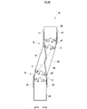
- FIG. 4A is a plan view showing a state when the tip bent portion of the inner tube of FIG. 1 is linear.
- FIG. 4B is a plan view showing a state when the tip bent portion is bent.
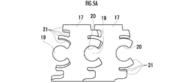
- FIG. 5A is a plan view showing a state when the two cylindrical members at the tip bending portion of the inner tube of FIG. 1 are linear.
- FIG. 5B is a side view of FIG. 5A.
- FIG. 5C is a plan view showing a state when the two cylindrical members are bent.
- FIG. 1 and 2 show an endoscopic treatment apparatus including an inner tube according to an embodiment of the present invention.
- the endoscopic treatment device 1 includes an inner tube 2 into which a flexible endoscope 3 is inserted and a tip of which protrudes from the tip, and a flexible treatment tool. It is provided with a plurality of inner tubes 4 into which the inner tubes 2 and 4 are inserted and protrude from the tip, and an outer tube 5 into which the inner tubes 2 and 4 are inserted and the tips of the inner tubes 2 and 4 protrude from the tip.
- the inner tubes 2 and 4 are arranged between the inner wall of the outer tube 5 and its central axis A.
- Each inner tube 4 includes first and second wires 6 and 7 whose base end portions are pulled in the base end direction along the inner tube 4.
- the side far from the central axis A of the outer tube 5 is the outer s1
- the near side is the inner s2
- the direction connecting the tip and the proximal end thereof is defined as the vertical direction D.
- the tip of the inner tube 4 is provided with a tip bent portion 10 having a first bent portion 8 and a second bent portion 9 located on the proximal end side of the first bent portion 8.
- the first bent portion 8 has a tip portion that is linear with respect to the base end portion thereof, and is between the tip end portion and the base end portion.
- the tip of the inner tube 4 is configured to be bendable in the inner s2 direction by being rotatably connected in the inner s2 direction about the first rotation axis a1 extending along the vertical direction D.
- the second bent portion 9 extends from the state in which the tip portion thereof is linear with respect to the base end portion in the vertical direction D between the tip portion and the base end portion.
- the tip of the inner tube 4 is configured to be bendable in the outer s1 direction by being rotatably connected in the outer s1 direction about the moving axis a2.
- the tip bending portion 10 has first and second fixing portions 11 and 12 for fixing the tips of the first and second wires 6 and 7 to the inner s2 and the outer s1 on the tip side of the first bent portion 8, respectively. Be prepared. Further, the tip bending portion 10 is provided between the first bending portion 8 and the second bending portion 9, and the first and third restraining portions 13 that restrain the passing positions of the first and second wires 6 and 7, respectively. , 14.
- the first restraint portion 13 is configured such that the first wire 6 passes through s2 inside the first rotation axis a1 and s1 outside the second rotation axis a2.
- the third restraint portion 14 restrains the passing position of the second wire 7 so that the second wire 7 passes through the outer s1 of the first rotation axis a1 and the inner side s2 of the second rotation axis a2.
- the tip bent portion 10 is provided on the proximal end side of the second bent portion 9, and the first and second wires 6 and 7 pass through the outer s1 and the inner s2 of the second rotation axis a2, respectively.
- the second and fourth restraint portions 15 and 16 that restrain the passing positions of the first and second wires 6 and 7, respectively, are provided. Therefore, the first and second wires 6 and 7 form a spiral that swirls around the tip bending portion 10 by 180 ° in opposite sides from the tip side to the base end side.
- the first and second bent portions 8 and 9 are composed of two or three or more cylindrical members 17 and 18 that are continuously connected.
- the cylindrical member 18 is a cylindrical member arranged on both sides of each of the first and second bent portions 8 and 9 in the tip bent portion 10.
- the cylindrical member 17 is a cylindrical member arranged between the cylindrical members 18 on both sides of the tip bent portion 10.
- the cylindrical member 17 may be omitted, and the cylindrical members 18 may be configured to be adjacent to each other.
- 5A to 5C show a cylindrical member 17 which is adjacent to each other in the first bent portion 8 or the second bent portion 9 and is in a linear state when viewed from above, and the cylindrical member 17 is viewed from the side surface. A state and a state in which the cylindrical member 17 in a bent state is viewed from above are shown.
- FIGS. 5A to 5C Cylindrical members 18 are connected to both sides of the two connected cylindrical members 17, and a first bent portion 8 or a second bent portion 9 is formed.
- one of the cylindrical members 17 adjacent to each other has two partially circular convex portions 19 opposite to each other in the vertical direction D on the side of the other cylindrical member 17.
- the two circular convex portions 19 include the central axis of the cylindrical member 17 and are located at positions symmetrical with respect to the plane of symmetry perpendicular to the vertical direction D.
- the other cylindrical member 17 has two partially circular concave portions 20 on the side of the one cylindrical member 17 at positions symmetrical with respect to the plane of symmetry. Then, the two circular protrusions 19 of one cylindrical member 17 and the two circular recesses 20 of the other cylindrical member 17 are aligned with each other, and each cylindrical member 17 is perpendicular to the plane of symmetry. They are connected so that they can rotate with each other around a rotating axis.
- one and the other cylindrical member 17 are arranged in a state of FIG. 5A in which the rotation range between each other is arranged linearly with each other and a state of being bent at a predetermined angle ⁇ with each other.
- Each has an abutting sliding surface 21 that abuts or slides against each other to limit it to the state and prevent it from separating from each other.
- the one and the other cylindrical member 17 and the cylindrical member 18 adjacent to each other are also connected and contacted by fitting the circular convex portion 19 and the circular concave portion 20 in the same manner.
- the sliding surfaces 21 limit the range of rotation between them and prevent them from separating from each other.
- a slide pipe 23, slide knobs 24 and 25, and a degassing prevention valve 26 are provided at the base end of each inner tube 4.
- the slide pipe 23 is connected to the tip bent portion 10 by a guide pipe 27.
- the degassing prevention valve 26 of each inner tube 4 is connected to the slide pipe 23 via the valve connector 28, and has a function of preventing air leakage from the inner tube 4 into which the treatment tool 29 is not inserted.
- the first and second wires 6 and 7, respectively, are embedded in the guide pipe 27 along the axial direction of the guide pipe 27 after passing through the second and fourth restraint portions 15 and 16, respectively, and the base end portion is a slide knob 24. , 25 fixed.
- the slide knobs 24 and 25 are configured to be slidable with respect to the slide pipe 23. Therefore, when the tip bending portion 10 of the inner tube 4 protrudes from the tip of the outer tube 5, the tip bending portion 10 is in a linear state as shown in FIG. 4A by pulling the slide knob 24 toward the base end side. Can be bent as shown in FIG. 4B. On the contrary, by pulling the slide knob 25 toward the base end side, the tip bent portion 10 can be returned to a straight line that is not bent as shown in FIG. 4A.
- the slide knob 24 is provided so that the stopper ring 30 can rotate.
- the stopper ring 30 can rotate between the rotational position of the slide pipe 23 standing outward in the radial direction and the tilted rotational position. With the slide knob 24 pulled toward the base end side, the stopper ring 30 is tilted and hooked on the valve connector 28 to fix the pulled state.
- an opening device 32 for maintaining the open state of the anus 31 and protecting the anus 31 is provided in the anus. It is attached to 31. Then, the valve cap 33 for the opening device 32 is attached to the opening device 32. The valve cap 33 allows the endoscopic treatment device 1 to be introduced from the opening formed by the opening device 32 and maintains the airtightness of the abdominal cavity.
- the inner tubes 2 and 4 are in a state of being buried without protruding from the tip of the outer tube 5.
- the endoscope 3 is inserted into the inner tube 2, and the treatment tool 29 is inserted into each inner tube 4. At this time, the endoscope 3 and the treatment tool 29 are in a state of being buried without protruding from the tips of the inner tubes 2 and 4.
- the endoscopic treatment device 1 is inserted into the rectum 34 via the valve cap 33 for the mouth opening device.
- the inner tubes 2 and 4 are advanced so that the respective tip portions protrude from the tip end of the outer tube 5.
- the tip bending portion 10 of the inner tube 4 is bent.
- the tip sides of the tip bending portions 10 are separated from each other in the left-right direction and face each other in a substantially parallel state.
- the endoscope 3 and the treatment tool 29 are advanced and protruded from the tips of the inner tubes 2 and 4.
- the tip portions of the treatment tools 29 are brought into a state of being close to each other by returning to the original state of being elastically deformed in a straight line.
- the tip portion of the endoscope 3 is in a state of facing the tip portion of each of the treatment tools 29 which are close to each other by returning to the original state in which the endoscope 3 is elastically deformed in a straight line.
- the procedure can be performed by bringing the treatment tool 29 close to the treatment portion while observing the treatment portion and the treatment tool 29 in the rectum 34 with the endoscope 3.
- the tip bending portion 10 of each inner tube 2 is bent in a substantially S shape, and the treatment tool 29 bends the tip so that the tip portions of the tip bending portions 10 are separated from each other and substantially parallel to each other. It is projected from the portion 10. Therefore, the amount of bending of the treatment tool 29 when the treatment tool 29 is directed toward the portion to be treated can be reduced. Therefore, surgery in a relatively narrow body cavity such as rectal surgery can be easily performed.
- the tip portions of the tip bending portions 10 are separated from each other and substantially parallel to each other, so that the treatment tool 29 is formed in a pre-bent shape.
- the treatment tool 29 when the treatment tool 29 is inserted into the inner tube 2 in a linearly extended state from the bent state and the tip portion of the treatment tool 29 is projected from the inner tube 2, the treatment tool 29 is in the original bent state. You can try to go back to. As a result, the treatment tool 29 can be bent inward with each other as shown in FIG. 1 without providing an operation portion on the treatment tool 29.
- first and second bent portions 8 and 9 of the tip bent portion 10 are two or three or more by simply laser-processing the cylindrical member for forming the tip bent portion 10 into the shape of the cylindrical members 17 and 18. It can be easily manufactured as a state in which the cylindrical members 17 and 18 are continuously connected.
- the bent end portion 10 of the inner tube 2 is not limited to a perfect circular shape in cross section, but may be circular (cylindrical) or slightly elliptical or polygonal.
- the tip of the inner tube 2 for the endoscope 3 may be provided with a bent portion similar to the tip bent portion 10 of the inner tube 4 for the treatment tool 29.
- the treatment tool 29 may have a joint portion at its tip and can be bent via a wire.
Landscapes
- Health & Medical Sciences (AREA)
- Life Sciences & Earth Sciences (AREA)
- Surgery (AREA)
- Animal Behavior & Ethology (AREA)
- Public Health (AREA)
- Engineering & Computer Science (AREA)
- Biomedical Technology (AREA)
- Heart & Thoracic Surgery (AREA)
- Medical Informatics (AREA)
- Molecular Biology (AREA)
- Pathology (AREA)
- General Health & Medical Sciences (AREA)
- Nuclear Medicine, Radiotherapy & Molecular Imaging (AREA)
- Veterinary Medicine (AREA)
- Physics & Mathematics (AREA)
- Biophysics (AREA)
- Optics & Photonics (AREA)
- Radiology & Medical Imaging (AREA)
- Surgical Instruments (AREA)
- Endoscopes (AREA)
Abstract
本発明の目的は、内視鏡や処置具を大きく屈曲させる必要なく被処置部に対向させることを可能にする医療用のインナーチューブを提供することにある。 医療用のインナーチューブ(4)は、基端部がインナーチューブ(4)に沿って牽引される第1ワイヤ(6)を備える。インナーチューブ(4)の先端部には、アウターチューブ(5)の中心軸線Aに近い内側に屈曲可能な第1屈曲部(8)と、外側に屈曲可能な第2屈曲部(9)とを備え、これらが屈曲していない状態では直線状となる先端屈曲部(10)が設けられる。先端屈曲部(10)は、第1ワイヤ(6)の先端部を、第1屈曲部(8)よりも先端側の前記内側に固定する第1固定部(11)と、第1ワイヤ(6)の通過位置を拘束する第1拘束部(13)及び第2拘束部(15)とを備える。
Description
本発明は、医療用の処置具等を挿入して体腔内に導入するための医療用のインナーチューブに関する。
従来、可撓性を有する内視鏡及びその観察下で使用される処置具がそれぞれ挿入される複数の可撓性を有するインナーチューブと、インナーチューブが挿入されてその先端部が先端から突出するアウターチューブとを備える内視鏡治療装置が知られている(例えば、特許文献1参照)。
この内視鏡治療装置では、インナーチューブの先端部に屈曲可能な首振りパイプが取り付けられる。首振りパイプの先端側には2本のワイヤ部材の先端部が固定される。首振りパイプは、一方のワイヤ部材を牽引することによりアウターチューブの径方向外側に屈曲させ、他方のワイヤ部材を牽引することにより、直線状に戻すことができるようになっている。
この内視鏡治療装置を用いて腹腔鏡手術を行う際には、アウターチューブに複数のインナーチューブを挿入して取り付け、各インナーチューブに内視鏡及び処置具を挿入した状態の内視鏡治療装置が、開創部に装着した開創器に取り付けた開創器用バルブキャップを介して体腔内に挿入される。
そして、各インナーチューブの先端屈曲部をアウターチューブの先端から突出させ、ワイヤ部材を牽引して首振りパイプを屈曲させる。さらに、内視鏡及び処置具の先端部を各インナーチューブの先端から突出させ、該先端部を屈曲させて手技が行われる。
これによれば、各インナーチューブの先端屈曲部を外側に屈曲させ、内視鏡及び処置具の先端部を内側に屈曲させて手技を行うことができる。このため、十分な内視鏡の視野と処置具による作業空間を確保することができるとともに、各処置具間の距離を把握し易いので、腹腔鏡手術を容易に行うことができる。
しかしながら、特許文献1に記載の内視鏡治療装置では、内視鏡及び処置具は、インナーチューブの先端屈曲部によって、外側に向かって突出されるため、被処置部に対向させるためには、内側に大きく屈曲させなければならないという不都合があった。
本発明の目的は、かかる従来技術の課題に鑑み、内視鏡や処置具を大きく屈曲させる必要なく被処置部に対向させることを可能にする医療用のインナーチューブを提供することにある。
本発明の医療用のインナーチューブは、
アウターチューブに対してその内壁と中心軸線との間に位置するように挿入されてその先端から先端部が突出し、可撓性の処置具又は可撓性の内視鏡が挿入されてその先端部が先端から突出する医療用のインナーチューブであって、
インナーチューブにおいて、アウターチューブの軸線から遠い側を外側、アウターチューブの軸線に近い側を内側、先端及び基端を結ぶ方向と前記外側及び前記内側を結ぶ方向とに直交する方向を上下方向と規定すると、
基端部がインナーチューブに沿って基端方向に牽引される第1ワイヤを備え、
インナーチューブの先端部には、第1屈曲部と、該第1屈曲部よりも基端側に位置する第2屈曲部とを有する先端屈曲部が設けられ、
前記第1屈曲部は、その先端部を、その基端部に対して直線状をなしている状態から、該先端部と該基端部との間において前記上下方向に沿って延びる第1回動軸線を中心として前記内側方向に回動可能に接続されることでインナーチューブの先端部を該内側方向に屈曲可能に構成され、
前記第2屈曲部は、その先端部を、その基端部に対して直線状をなしている状態から、該先端部と該基端部との間において前記上下方向に沿って延びる第2回動軸線を中心として前記外側方向に回動可能に接続されることでインナーチューブの先端部を該外側方向に屈曲可能に構成され、
前記先端屈曲部は、
前記第1ワイヤの先端部を、前記第1屈曲部よりも先端側の前記内側に固定する第1固定部と、
前記第1屈曲部と前記第2屈曲部との間に設けられ、前記第1ワイヤが前記第1回動軸線よりも前記内側、かつ、前記第2回動軸線よりも前記外側を通るように該第1ワイヤの通過位置を拘束する第1拘束部と、
前記第2屈曲部よりも基端側に設けられ、前記第1ワイヤが前記第2回動軸線の前記外側を通るように該第1ワイヤの通過位置を拘束する第2拘束部とを備えることを特徴とする。
アウターチューブに対してその内壁と中心軸線との間に位置するように挿入されてその先端から先端部が突出し、可撓性の処置具又は可撓性の内視鏡が挿入されてその先端部が先端から突出する医療用のインナーチューブであって、
インナーチューブにおいて、アウターチューブの軸線から遠い側を外側、アウターチューブの軸線に近い側を内側、先端及び基端を結ぶ方向と前記外側及び前記内側を結ぶ方向とに直交する方向を上下方向と規定すると、
基端部がインナーチューブに沿って基端方向に牽引される第1ワイヤを備え、
インナーチューブの先端部には、第1屈曲部と、該第1屈曲部よりも基端側に位置する第2屈曲部とを有する先端屈曲部が設けられ、
前記第1屈曲部は、その先端部を、その基端部に対して直線状をなしている状態から、該先端部と該基端部との間において前記上下方向に沿って延びる第1回動軸線を中心として前記内側方向に回動可能に接続されることでインナーチューブの先端部を該内側方向に屈曲可能に構成され、
前記第2屈曲部は、その先端部を、その基端部に対して直線状をなしている状態から、該先端部と該基端部との間において前記上下方向に沿って延びる第2回動軸線を中心として前記外側方向に回動可能に接続されることでインナーチューブの先端部を該外側方向に屈曲可能に構成され、
前記先端屈曲部は、
前記第1ワイヤの先端部を、前記第1屈曲部よりも先端側の前記内側に固定する第1固定部と、
前記第1屈曲部と前記第2屈曲部との間に設けられ、前記第1ワイヤが前記第1回動軸線よりも前記内側、かつ、前記第2回動軸線よりも前記外側を通るように該第1ワイヤの通過位置を拘束する第1拘束部と、
前記第2屈曲部よりも基端側に設けられ、前記第1ワイヤが前記第2回動軸線の前記外側を通るように該第1ワイヤの通過位置を拘束する第2拘束部とを備えることを特徴とする。
この構成において、先端屈曲部が直線状をなしている状態において第1ワイヤが牽引されると、インナーチューブの内側に位置する第1固定部が外側に位置する第2拘束部の方向に引き付けられる。そして、第1、第2屈曲部は、それぞれインナーチューブの内側、外側に回動可能であり、第1ワイヤは第1回動軸線の内側、及び第2回動軸線の外側を通っているので、この第1ワイヤの牽引により第1、第2屈曲部が屈曲する。
これにより、先端屈曲部は、全体としてS字状に屈曲し、その先端部が外側にシフトした状態となる。したがって、この状態のインナーチューブから突出した内視鏡や処置具の先端部を、大きく屈曲させる必要なく被処置部に対向させることが可能となる。
本発明において、
基端部がインナーチューブに沿って基端方向に牽引される第2ワイヤを備え、
前記先端屈曲部は、
前記第2ワイヤの先端部を、前記第1屈曲部よりも先端側の前記外側に固定する第2固定部と、
前記第1屈曲部と前記第2屈曲部との間に設けられ、前記第2ワイヤが前記第1回動軸線よりも前記外側、かつ、前記第2回動軸線よりも前記内側を通るように該第2ワイヤの通過位置を拘束する第3拘束部と、
前記第2屈曲部よりも基端側に設けられ、前記第2ワイヤが前記第2回動軸線の前記内側を通るように該第2ワイヤの通過位置を拘束する第4拘束部とを備えるのが好ましい。
基端部がインナーチューブに沿って基端方向に牽引される第2ワイヤを備え、
前記先端屈曲部は、
前記第2ワイヤの先端部を、前記第1屈曲部よりも先端側の前記外側に固定する第2固定部と、
前記第1屈曲部と前記第2屈曲部との間に設けられ、前記第2ワイヤが前記第1回動軸線よりも前記外側、かつ、前記第2回動軸線よりも前記内側を通るように該第2ワイヤの通過位置を拘束する第3拘束部と、
前記第2屈曲部よりも基端側に設けられ、前記第2ワイヤが前記第2回動軸線の前記内側を通るように該第2ワイヤの通過位置を拘束する第4拘束部とを備えるのが好ましい。
これによれば、上記のようにS字状に屈曲した状態のインナーチューブの先端屈曲部を、第2ワイヤを基端方向に牽引することにより、直線状の状態に戻すことができる。
本発明において、
前記第1、第2屈曲部は、それぞれ連続して接続された2又は3以上の円筒状部材で構成され、
前記円筒状部材のうち、相互に隣接する一方の円筒状部材は、他方の円筒状部材の側に、該円筒状部材の中心軸線を含み、前記上下方向に垂直な対称面について対称な位置に部分円状の2つの円状凸部を有し、他方の円筒状部材は該2つの円状凸部に嵌合した部分円状の2つの円状凹部を有し、
前記相互に隣接する一方及び他方の円筒状部材は、前記円状凸部及び前記円状凹部を介して前記対称面に垂直な回動軸線の周りで相互に回動し得るように接続されており、
前記一方及び他方の円筒状部材は、相互間の回動範囲を、相互に直線状に配置される状態と、相互に所定角度で屈曲した状態で配置される状態との間に制限するとともに相互に分離するのを阻止すべく相互に当接し又は摺動する当接摺動面をそれぞれ有するのが好ましい。
前記第1、第2屈曲部は、それぞれ連続して接続された2又は3以上の円筒状部材で構成され、
前記円筒状部材のうち、相互に隣接する一方の円筒状部材は、他方の円筒状部材の側に、該円筒状部材の中心軸線を含み、前記上下方向に垂直な対称面について対称な位置に部分円状の2つの円状凸部を有し、他方の円筒状部材は該2つの円状凸部に嵌合した部分円状の2つの円状凹部を有し、
前記相互に隣接する一方及び他方の円筒状部材は、前記円状凸部及び前記円状凹部を介して前記対称面に垂直な回動軸線の周りで相互に回動し得るように接続されており、
前記一方及び他方の円筒状部材は、相互間の回動範囲を、相互に直線状に配置される状態と、相互に所定角度で屈曲した状態で配置される状態との間に制限するとともに相互に分離するのを阻止すべく相互に当接し又は摺動する当接摺動面をそれぞれ有するのが好ましい。
これによれば、先端屈曲部を形成するための円筒状の部材を円筒状部材の形状にレーザ加工するだけで、2又は3以上の円筒状部材が連続して接続された状態の第1、第2屈曲部を形成している先端屈曲部を容易に製造することができる。
以下、図面を用いて本発明の実施形態を説明する。図1及び図2は、本発明の一実施形態に係るインナーチューブを備える内視鏡治療装置を示す。
図1及び図2に示すように、この内視鏡治療装置1は、可撓性の内視鏡3が挿入されてその先端部が先端から突出するインナーチューブ2と、可撓性の処置具が挿入されて先端から突出する複数のインナーチューブ4と、各インナーチューブ2、4が挿入されてインナーチューブ2、4の先端部が先端から突出するアウターチューブ5とを備える。各インナーチューブ2、4は、アウターチューブ5の内壁とその中心軸線Aとの間に配置される。
各インナーチューブ4は、それぞれ基端部が該インナーチューブ4に沿って基端方向に牽引される第1、第2ワイヤ6、7を備える。
ここで、図3A及び図3Bに示すように、各インナーチューブ2、4において、アウターチューブ5の中心軸線Aから遠い側を外側s1、近い側を内側s2、先端及び基端を結ぶ方向と該外側s1及び内側s2を結ぶ方向とに直交する方向を上下方向Dと規定する。
インナーチューブ4の先端部には、第1屈曲部8と、第1屈曲部8よりも基端側に位置する第2屈曲部9とを有する先端屈曲部10が設けられる。
図4A及び図4Bは、先端屈曲部10が直線状になっているとき及び屈曲しているときの様子を示す。図4A及び図4Bに示すように、第1屈曲部8は、その先端部を、その基端部に対して直線状をなしている状態から、該先端部と該基端部との間において上下方向Dに沿って延びる第1回動軸線a1を中心として内側s2方向に回動可能に接続されることでインナーチューブ4の先端部を内側s2方向に屈曲可能に構成される。
第2屈曲部9は、その先端部を、その基端部に対して直線状をなしている状態から、該先端部と該基端部との間において上下方向Dに沿って延びる第2回動軸線a2を中心として外側s1方向に回動可能に接続されることでインナーチューブ4の先端部を外側s1方向に屈曲可能に構成される。
先端屈曲部10は、第1、第2ワイヤ6、7の先端部を、第1屈曲部8よりも先端側の内側s2、外側s1にそれぞれ固定する第1、第2固定部11、12を備える。また、先端屈曲部10は、第1屈曲部8と第2屈曲部9との間に設けられ、第1、第2ワイヤ6、7の通過位置をそれぞれ拘束する第1、第3拘束部13、14を備える。
第1拘束部13は、第1ワイヤ6が第1回動軸線a1よりも内側s2、かつ、第2回動軸線a2よりも外側s1を通るように構成される。第3拘束部14は、第2ワイヤ7が第1回動軸線a1よりも外側s1、かつ、第2回動軸線a2よりも内側s2を通るように第2ワイヤ7の通過位置を拘束する。
また、先端屈曲部10は、第2屈曲部9よりも基端側に設けられ、第1、第2ワイヤ6、7が第2回動軸線a2の外側s1、内側s2をそれぞれ通るように第1、第2ワイヤ6、7の通過位置をそれぞれ拘束する第2、第4拘束部15、16を備える。したがって、第1、第2ワイヤ6、7は、先端屈曲部10の周りを、その先端側から基端側にかけて相互に反対側に180°旋回する螺旋を形成している。
第1、第2屈曲部8、9は、連続して接続された2又は3以上の円筒状部材17、18で構成される。円筒状部材18は、先端屈曲部10において、第1、第2屈曲部8、9それぞれの両側に配置された円筒状部材である。円筒状部材17は、先端屈曲部10において、該両側の円筒状部材18の間に配置された円筒状部材である。なお、円筒状部材17を省略し、円筒状部材18同士が隣接するように構成してもよい。
図5A~図5Cは、それぞれ第1屈曲部8又は第2屈曲部9において相互に隣接し、直線状態にある円筒状部材17を上方から見た様子、該円筒状部材17を側面から見た様子、及び屈曲状態にある該円筒状部材17を上方から見た様子をそれぞれ示す。
ただし、この場合、第1、第2屈曲部8、9のそれぞれにおいて円筒状部材17が1つのみ用いられている図4A及び図4Bの場合と異なり、図5A~図5Cに示されている接続された2つの円筒状部材17の両側に円筒状部材18が接続され、第1屈曲部8又は第2屈曲部9が構成される。
図5A及び図5Bに示すように、相互に隣接する一方の円筒状部材17は、他方の円筒状部材17の側に、部分円状の2つの円状凸部19をそれぞれ上下方向Dにおいて反対側に有する。2つの円状凸部19は、円筒状部材17の中心軸線を含み、上下方向Dに垂直な対称面について対称な位置に位置する。
他方の円筒状部材17は、一方の円筒状部材17の側に2つの部分円状の円状凹部20を前記対称面について対称な位置に有する。そして、一方の円筒状部材17の2つの円状凸部19と、他方の円筒状部材17の2つの円状凹部20とが篏合して、各円筒状部材17は、前記対称面に垂直な回動軸線の周りで相互に回動し得るように接続されている。
また、一方及び他方の円筒状部材17は、相互間の回動範囲を、相互に直線状に配置される図5Aの状態と、相互に所定角度αで屈曲した状態で配置される図5Cの状態との間に制限するとともに相互に分離するのを阻止すべく相互に当接し又は摺動する当接摺動面21をそれぞれ有する。
また、上記の一方及び他方の円筒状部材17と、それぞれに隣接する円筒状部材18との間も、同様にして円状凸部19と円状凹部20との嵌合により接続し、当接摺動面21により相互間の回動範囲が制限され、かつ相互に分離することが阻止される。
図1及び図2に示すように、各インナーチューブ4の基端部には、スライドパイプ23、スライドノブ24、25、及び脱気防止弁26が設けられる。スライドパイプ23は、先端屈曲部10に対して、案内管27により接続される。各インナーチューブ4の脱気防止弁26は、バルブコネクタ28を介してスライドパイプ23に接続され、処置具29が挿入されていないインナーチューブ4から空気漏れが生じることを防ぐ機能を有する。
第1、第2ワイヤ6、7は、それぞれ、第2、第4拘束部15、16を経た後、案内管27の軸線方向に沿って案内管27に埋設され、基端部がスライドノブ24、25に固定される。
スライドノブ24、25は、スライドパイプ23に対して摺動自在に構成される。このため、インナーチューブ4の先端屈曲部10がアウターチューブ5の先端から突出しているときに、スライドノブ24を基端側に牽引することによって、図4Aのように直線状態にある先端屈曲部10を、図4Bのように屈曲させることができる。逆に、スライドノブ25を基端側に牽引することによって先端屈曲部10を、図4Aのように、屈曲していない直線状に戻すことができる。
スライドノブ24には、ストッパリング30が回動し得るように設けられる。ストッパリング30は、スライドパイプ23の径方向外方に立てられた回動位置と、倒された回動位置との間で回動し得るようになっている。スライドノブ24を基端側に牽引した状態で、ストッパリング30を倒してバルブコネクタ28に掛けることにより、該牽引状態が固定される。
この構成において、内視鏡治療装置1を使用する際には、まず、図1に示すように、肛門部31の開口状態を維持するとともに肛門部31を保護するための開口器32が肛門部31に装着される。そして、開口器32に対して、開口器32用のバルブキャップ33を取り付ける。バルブキャップ33は、開口器32により形成された開口部から内視鏡治療装置1を導入可能にするとともに腹腔の気密性を維持する。
次に、アウターチューブ5にインナーチューブ2、4を挿入して取り付ける。本実施形態では、図1に示すように、処置具29用の2つのインナーチューブ4と、内視鏡3用の1つのインナーチューブ2が周方向に60度ずつ離れるように取り付けられる。また、このとき、2つのインナーチューブ4の先端屈曲部10の先端側が、後述の屈曲時に相互に離間するような該周方向の回転角度で取り付けられる。
なお、この時点では、インナーチューブ2、4は、アウターチューブ5の先端から突出せず埋没した状態となっている。
次に、インナーチューブ2に内視鏡3を挿入し、各インナーチューブ4に処置具29を挿入する。このとき、内視鏡3及び処置具29は、インナーチューブ2、4の先端から突出せず埋没した状態となっている。
次に、内視鏡治療装置1を、開口器用のバルブキャップ33を介して、直腸34内に挿入する。そして、インナーチューブ2、4を前進させてアウターチューブ5の先端からそれぞれの先端部を突出させる。さらに、各インナーチューブ4のスライドノブ24を牽引することによって、インナーチューブ4の先端屈曲部10を屈曲させる。これにより、各先端屈曲部10の先端側は、相互に左右方向に離間して、ほぼ平行な状態で対峙した状態となる。
次に、図1及び図2に示すように、内視鏡3及び処置具29を前進させ、インナーチューブ2、4の先端から突出させる。このとき、各処置具29の先端部は直線状に弾性変形されていた状態が元に復帰することにより、相互に近接した状態となる。また、内視鏡3の先端部は、直線状に弾性変形されていた状態が元に復帰することにより、相互に近接した各処置具29の先端部の方向を向いた状態となる。
したがって、この後、内視鏡3により直腸34内の被処置部及び処置具29を観察しながら、処置具29を被処置部に近接させて、手技を行うことができる。
本実施形態によれば、各インナーチューブ2の先端屈曲部10をほぼS字状に屈曲させ、各先端屈曲部10の先端部が相互に離れてかつほぼ平行な状態として処置具29が先端屈曲部10から突出される。このため、処置具29を被処置部に向ける際の処置具29の屈曲量を少なくすることができる。したがって、直腸手術のような比較的狭い体腔内の手術も容易に行うことができる。
また、処置具29の屈曲量を少なくすることができるので、各先端屈曲部10の先端部が相互に離れてかつほぼ平行な状態となるので、処置具29を予め屈曲した形状に形成しつつ、直線状に屈曲可能に構成することができる。
つまり、処置具29を屈曲している状態から直線状に伸ばした状態でインナーチューブ2に挿入し、処置具29の先端部をインナーチューブ2から突出させると、処置具29を元の屈曲した状態に戻るようにすることができる。これにより、処置具29に操作部を設けることなく、処置具29を図1のように相互に内側に屈曲させることができる。
また、先端屈曲部10の第1、第2屈曲部8、9は、それを形成するための円筒状の部材を円筒状部材17、18の形状にレーザ加工するだけで、2又は3以上の円筒状部材17、18が連続して接続された状態のものとして、容易に製造することができる。
以上、本発明の実施形態について説明したが、本発明は、これに限定されることなく変形して実施することができる。例えば、インナーチューブ2の先端屈曲部10は、断面形状が真円状に限らず、円状(円筒状)であればよく、多少楕円状や多角形状であってもよい。
また、内視鏡3用のインナーチューブ2の先端部に、処置具29用のインナーチューブ4の先端屈曲部10と同様の屈曲部を設けてもよい。
また、処置具29は、その先端部に関節部を有し、ワイヤを介して屈曲できるものであってもよい。
1…内視鏡治療装置、2、4…インナーチューブ、3…内視鏡、5…アウターチューブ、6…第1ワイヤ、7…第2ワイヤ、8…第1屈曲部、9…第2屈曲部、10…先端屈曲部、11…第1固定部、12…第2固定部、13…第1拘束部、14…第3拘束部、15…第2拘束部、16…第4拘束部、17、18…円筒状部材、19…円状凸部、20…円状凹部、21…当接摺動面、23…スライドパイプ、24、25…スライドノブ、26…脱気防止弁、27…案内管、28…バルブコネクタ、29…処置具、30…ストッパリング、31…肛門部、32…開口器、33…バルブキャップ、34…直腸。
Claims (3)
- アウターチューブに対してその内壁と中心軸線との間に位置するように挿入されてその先端から先端部が突出し、可撓性の処置具又は可撓性の内視鏡が挿入されてその先端部が先端から突出する医療用のインナーチューブであって、
インナーチューブにおいて、アウターチューブの軸線から遠い側を外側、アウターチューブの軸線に近い側を内側、先端及び基端を結ぶ方向と前記外側及び前記内側を結ぶ方向とに直交する方向を上下方向と規定すると、
基端部がインナーチューブに沿って基端方向に牽引される第1ワイヤを備え、
インナーチューブの先端部には、第1屈曲部と、該第1屈曲部よりも基端側に位置する第2屈曲部とを有する先端屈曲部が設けられ、
前記第1屈曲部は、その先端部を、その基端部に対して直線状をなしている状態から、該先端部と該基端部との間において前記上下方向に沿って延びる第1回動軸線を中心として前記内側方向に回動可能に接続されることでインナーチューブの先端部を該内側方向に屈曲可能に構成され、
前記第2屈曲部は、その先端部を、その基端部に対して直線状をなしている状態から、該先端部と該基端部との間において前記上下方向に沿って延びる第2回動軸線を中心として前記外側方向に回動可能に接続されることでインナーチューブの先端部を該外側方向に屈曲可能に構成され、
前記先端屈曲部は、
前記第1ワイヤの先端部を、前記第1屈曲部よりも先端側の前記内側に固定する第1固定部と、
前記第1屈曲部と前記第2屈曲部との間に設けられ、前記第1ワイヤが前記第1回動軸線よりも前記内側、かつ、前記第2回動軸線よりも前記外側を通るように該第1ワイヤの通過位置を拘束する第1拘束部と、
前記第2屈曲部よりも基端側に設けられ、前記第1ワイヤが前記第2回動軸線の前記外側を通るように該第1ワイヤの通過位置を拘束する第2拘束部とを備えることを特徴とする医療用のインナーチューブ。 - 基端部がインナーチューブに沿って基端方向に牽引される第2ワイヤを備え、
前記先端屈曲部は、
前記第2ワイヤの先端部を、前記第1屈曲部よりも先端側の前記外側に固定する第2固定部と、
前記第1屈曲部と前記第2屈曲部との間に設けられ、前記第2ワイヤが前記第1回動軸線よりも前記外側、かつ、前記第2回動軸線よりも前記内側を通るように該第2ワイヤの通過位置を拘束する第3拘束部と、
前記第2屈曲部よりも基端側に設けられ、前記第2ワイヤが前記第2回動軸線の前記内側を通るように該第2ワイヤの通過位置を拘束する第4拘束部とを備えることを特徴とする請求項1に記載の医療用のインナーチューブ。 - 前記第1、第2屈曲部は、それぞれ連続して接続された2又は3以上の円筒状部材で構成され、
前記円筒状部材のうち、相互に隣接する一方の円筒状部材は、他方の円筒状部材の側に、該円筒状部材の中心軸線を含み、前記上下方向に垂直な対称面について対称な位置に部分円状の2つの円状凸部を有し、他方の円筒状部材は該2つの円状凸部に嵌合した部分円状の2つの円状凹部を有し、
前記相互に隣接する一方及び他方の円筒状部材は、前記円状凸部及び前記円状凹部を介して前記対称面に垂直な回動軸線の周りで相互に回動し得るように接続されており、
前記一方及び他方の円筒状部材は、相互間の回動範囲を、相互に直線状に配置される状態と、相互に所定角度で屈曲した状態で配置される状態との間に制限するとともに相互に分離するのを阻止すべく相互に当接し又は摺動する当接摺動面をそれぞれ有することを特徴とする請求項2に記載の医療用のインナーチューブ。
Priority Applications (1)
| Application Number | Priority Date | Filing Date | Title |
|---|---|---|---|
| JP2021507282A JP7474993B2 (ja) | 2019-03-15 | 2020-03-12 | 医療用のインナーチューブ |
Applications Claiming Priority (2)
| Application Number | Priority Date | Filing Date | Title |
|---|---|---|---|
| JP2019048881 | 2019-03-15 | ||
| JP2019-048881 | 2019-03-15 |
Publications (1)
| Publication Number | Publication Date |
|---|---|
| WO2020189511A1 true WO2020189511A1 (ja) | 2020-09-24 |
Family
ID=72519853
Family Applications (1)
| Application Number | Title | Priority Date | Filing Date |
|---|---|---|---|
| PCT/JP2020/010864 Ceased WO2020189511A1 (ja) | 2019-03-15 | 2020-03-12 | 医療用のインナーチューブ |
Country Status (2)
| Country | Link |
|---|---|
| JP (1) | JP7474993B2 (ja) |
| WO (1) | WO2020189511A1 (ja) |
Citations (6)
| Publication number | Priority date | Publication date | Assignee | Title |
|---|---|---|---|---|
| JP2007275565A (ja) * | 2006-04-06 | 2007-10-25 | Olympus Medical Systems Corp | 医療器具 |
| WO2011070846A1 (ja) * | 2009-12-10 | 2011-06-16 | オリンパスメディカルシステムズ株式会社 | 医療用マニピュレータ |
| US20130131450A1 (en) * | 2011-11-21 | 2013-05-23 | Cook Medical Technologies Llc | Endoscope stabilization system |
| JP2015535702A (ja) * | 2012-09-19 | 2015-12-17 | ナンヤン テクノロジカル ユニヴァーシティNanyang Technological University | フレキシブルマスター‐スレーブロボット内視鏡システム |
| WO2017119108A1 (ja) * | 2016-01-07 | 2017-07-13 | 学校法人慶應義塾 | 内視鏡治療装置 |
| WO2018204202A1 (en) * | 2017-05-03 | 2018-11-08 | Canon U.S.A., Inc. | Steerable medical device and method |
Family Cites Families (1)
| Publication number | Priority date | Publication date | Assignee | Title |
|---|---|---|---|---|
| DE19535179A1 (de) * | 1995-09-22 | 1997-03-27 | Wolf Gmbh Richard | Abwinkelbares Rohr und Verfahren zu seiner Herstellung |
-
2020
- 2020-03-12 JP JP2021507282A patent/JP7474993B2/ja active Active
- 2020-03-12 WO PCT/JP2020/010864 patent/WO2020189511A1/ja not_active Ceased
Patent Citations (6)
| Publication number | Priority date | Publication date | Assignee | Title |
|---|---|---|---|---|
| JP2007275565A (ja) * | 2006-04-06 | 2007-10-25 | Olympus Medical Systems Corp | 医療器具 |
| WO2011070846A1 (ja) * | 2009-12-10 | 2011-06-16 | オリンパスメディカルシステムズ株式会社 | 医療用マニピュレータ |
| US20130131450A1 (en) * | 2011-11-21 | 2013-05-23 | Cook Medical Technologies Llc | Endoscope stabilization system |
| JP2015535702A (ja) * | 2012-09-19 | 2015-12-17 | ナンヤン テクノロジカル ユニヴァーシティNanyang Technological University | フレキシブルマスター‐スレーブロボット内視鏡システム |
| WO2017119108A1 (ja) * | 2016-01-07 | 2017-07-13 | 学校法人慶應義塾 | 内視鏡治療装置 |
| WO2018204202A1 (en) * | 2017-05-03 | 2018-11-08 | Canon U.S.A., Inc. | Steerable medical device and method |
Also Published As
| Publication number | Publication date |
|---|---|
| JP7474993B2 (ja) | 2024-04-26 |
| JPWO2020189511A1 (ja) | 2020-09-24 |
Similar Documents
| Publication | Publication Date | Title |
|---|---|---|
| JP7391956B2 (ja) | 管要素を備えるステアラブル機器 | |
| JP5301876B2 (ja) | シールを伴う可撓性カニューレ | |
| US20090062606A1 (en) | Endoscope guiding tube device | |
| JP2006239425A (ja) | 導入具シールアセンブリ | |
| US20080277853A1 (en) | Clip for coupling a surgical tool and scope | |
| JP6084341B2 (ja) | オーバーチューブ | |
| US20150282826A1 (en) | Endoscope treatment tool | |
| JP2008289881A (ja) | リブ付きシールを備えるアクセスアセンブリ | |
| JP5425695B2 (ja) | 内視鏡装置 | |
| JP5607778B2 (ja) | 外科用シールアセンブリ | |
| JP6516172B2 (ja) | 屈曲処置具用ヒンジ部材及びこのヒンジ部材を組み込んだ屈曲処置具 | |
| JP2008289892A (ja) | 枠アセンブリを備えた外科用入り口装置 | |
| WO2020121438A1 (ja) | 内視鏡用チャンネルユニット、内視鏡 | |
| US20140018631A1 (en) | Surgical seal assembly including a guard member | |
| CN107205620B (zh) | 内窥镜用前端罩 | |
| JP2009056056A (ja) | 内視鏡案内管装置 | |
| JP7474993B2 (ja) | 医療用のインナーチューブ | |
| CN117243547B (zh) | 蛇骨结构和内窥镜 | |
| JP2010221030A (ja) | センタリング機構を備えるアクセスポート | |
| US9585690B2 (en) | Surgical access device including universal seal mechanism associated with bellows | |
| JP7258271B2 (ja) | 経肛門手術具導入装置 | |
| JP2013176425A (ja) | 内視鏡案内管路用セパレータ、及びそれを用いた内視鏡案内管装置 | |
| KR20190029685A (ko) | 조향 가능 카테터 핸들 | |
| US10806488B2 (en) | Working sleeve for a trocar | |
| JP2016214282A (ja) | 内視鏡装置 |
Legal Events
| Date | Code | Title | Description |
|---|---|---|---|
| 121 | Ep: the epo has been informed by wipo that ep was designated in this application |
Ref document number: 20774753 Country of ref document: EP Kind code of ref document: A1 |
|
| ENP | Entry into the national phase |
Ref document number: 2021507282 Country of ref document: JP Kind code of ref document: A |
|
| NENP | Non-entry into the national phase |
Ref country code: DE |
|
| 122 | Ep: pct application non-entry in european phase |
Ref document number: 20774753 Country of ref document: EP Kind code of ref document: A1 |