WO2020189237A1 - タービン翼およびガスタービン - Google Patents
タービン翼およびガスタービン Download PDFInfo
- Publication number
- WO2020189237A1 WO2020189237A1 PCT/JP2020/008670 JP2020008670W WO2020189237A1 WO 2020189237 A1 WO2020189237 A1 WO 2020189237A1 JP 2020008670 W JP2020008670 W JP 2020008670W WO 2020189237 A1 WO2020189237 A1 WO 2020189237A1
- Authority
- WO
- WIPO (PCT)
- Prior art keywords
- fillet
- blade
- passage
- airfoil
- platform
- Prior art date
- Legal status (The legal status is an assumption and is not a legal conclusion. Google has not performed a legal analysis and makes no representation as to the accuracy of the status listed.)
- Ceased
Links
Images






Classifications
-
- F—MECHANICAL ENGINEERING; LIGHTING; HEATING; WEAPONS; BLASTING
- F01—MACHINES OR ENGINES IN GENERAL; ENGINE PLANTS IN GENERAL; STEAM ENGINES
- F01D—NON-POSITIVE DISPLACEMENT MACHINES OR ENGINES, e.g. STEAM TURBINES
- F01D5/00—Blades; Blade-carrying members; Heating, heat-insulating, cooling or antivibration means on the blades or the members
- F01D5/12—Blades
- F01D5/14—Form or construction
- F01D5/18—Hollow blades, i.e. blades with cooling or heating channels or cavities; Heating, heat-insulating or cooling means on blades
- F01D5/187—Convection cooling
-
- F—MECHANICAL ENGINEERING; LIGHTING; HEATING; WEAPONS; BLASTING
- F01—MACHINES OR ENGINES IN GENERAL; ENGINE PLANTS IN GENERAL; STEAM ENGINES
- F01D—NON-POSITIVE DISPLACEMENT MACHINES OR ENGINES, e.g. STEAM TURBINES
- F01D5/00—Blades; Blade-carrying members; Heating, heat-insulating, cooling or antivibration means on the blades or the members
- F01D5/12—Blades
- F01D5/14—Form or construction
- F01D5/141—Shape, i.e. outer, aerodynamic form
- F01D5/145—Means for influencing boundary layers or secondary circulations
-
- F—MECHANICAL ENGINEERING; LIGHTING; HEATING; WEAPONS; BLASTING
- F01—MACHINES OR ENGINES IN GENERAL; ENGINE PLANTS IN GENERAL; STEAM ENGINES
- F01D—NON-POSITIVE DISPLACEMENT MACHINES OR ENGINES, e.g. STEAM TURBINES
- F01D5/00—Blades; Blade-carrying members; Heating, heat-insulating, cooling or antivibration means on the blades or the members
- F01D5/12—Blades
- F01D5/14—Form or construction
- F01D5/18—Hollow blades, i.e. blades with cooling or heating channels or cavities; Heating, heat-insulating or cooling means on blades
- F01D5/182—Transpiration cooling
- F01D5/183—Blade walls being porous
-
- F—MECHANICAL ENGINEERING; LIGHTING; HEATING; WEAPONS; BLASTING
- F01—MACHINES OR ENGINES IN GENERAL; ENGINE PLANTS IN GENERAL; STEAM ENGINES
- F01D—NON-POSITIVE DISPLACEMENT MACHINES OR ENGINES, e.g. STEAM TURBINES
- F01D9/00—Stators
- F01D9/02—Nozzles; Nozzle boxes; Stator blades; Guide conduits, e.g. individual nozzles
- F01D9/023—Transition ducts between combustor cans and first stage of the turbine in gas-turbine engines; their cooling or sealings
-
- F—MECHANICAL ENGINEERING; LIGHTING; HEATING; WEAPONS; BLASTING
- F05—INDEXING SCHEMES RELATING TO ENGINES OR PUMPS IN VARIOUS SUBCLASSES OF CLASSES F01-F04
- F05D—INDEXING SCHEME FOR ASPECTS RELATING TO NON-POSITIVE-DISPLACEMENT MACHINES OR ENGINES, GAS-TURBINES OR JET-PROPULSION PLANTS
- F05D2220/00—Application
- F05D2220/30—Application in turbines
- F05D2220/32—Application in turbines in gas turbines
-
- F—MECHANICAL ENGINEERING; LIGHTING; HEATING; WEAPONS; BLASTING
- F05—INDEXING SCHEMES RELATING TO ENGINES OR PUMPS IN VARIOUS SUBCLASSES OF CLASSES F01-F04
- F05D—INDEXING SCHEME FOR ASPECTS RELATING TO NON-POSITIVE-DISPLACEMENT MACHINES OR ENGINES, GAS-TURBINES OR JET-PROPULSION PLANTS
- F05D2240/00—Components
- F05D2240/35—Combustors or associated equipment
-
- F—MECHANICAL ENGINEERING; LIGHTING; HEATING; WEAPONS; BLASTING
- F05—INDEXING SCHEMES RELATING TO ENGINES OR PUMPS IN VARIOUS SUBCLASSES OF CLASSES F01-F04
- F05D—INDEXING SCHEME FOR ASPECTS RELATING TO NON-POSITIVE-DISPLACEMENT MACHINES OR ENGINES, GAS-TURBINES OR JET-PROPULSION PLANTS
- F05D2240/00—Components
- F05D2240/80—Platforms for stationary or moving blades
- F05D2240/81—Cooled platforms
-
- F—MECHANICAL ENGINEERING; LIGHTING; HEATING; WEAPONS; BLASTING
- F05—INDEXING SCHEMES RELATING TO ENGINES OR PUMPS IN VARIOUS SUBCLASSES OF CLASSES F01-F04
- F05D—INDEXING SCHEME FOR ASPECTS RELATING TO NON-POSITIVE-DISPLACEMENT MACHINES OR ENGINES, GAS-TURBINES OR JET-PROPULSION PLANTS
- F05D2260/00—Function
- F05D2260/20—Heat transfer, e.g. cooling
-
- F—MECHANICAL ENGINEERING; LIGHTING; HEATING; WEAPONS; BLASTING
- F05—INDEXING SCHEMES RELATING TO ENGINES OR PUMPS IN VARIOUS SUBCLASSES OF CLASSES F01-F04
- F05D—INDEXING SCHEME FOR ASPECTS RELATING TO NON-POSITIVE-DISPLACEMENT MACHINES OR ENGINES, GAS-TURBINES OR JET-PROPULSION PLANTS
- F05D2260/00—Function
- F05D2260/20—Heat transfer, e.g. cooling
- F05D2260/202—Heat transfer, e.g. cooling by film cooling
Definitions
- the present invention relates to turbine blades such as moving blades and stationary blades applied to a gas turbine, and a gas turbine provided with the turbine blades.
- the gas turbine has a compressor, a combustor, and a turbine.
- the compressor compresses the air taken in from the air intake to obtain high-temperature, high-pressure compressed air.
- the combustor obtains high-temperature, high-pressure combustion gas by supplying fuel to compressed air and burning it.
- the turbine is driven by combustion gas and drives a coaxially connected generator.
- Patent Document 1 describes a rotor blade provided with a cooling air passage, and the cooling air is blown out from a hole on the trailing edge side after passing through the cooling air passage. Further, it is described that the thermal stress is reduced by providing an elliptical fillet portion between the blade base end portion and the connection portion of the platform in this rotor blade.
- the present invention solves the above-mentioned problems, and an object of the present invention is to provide a turbine blade and a gas turbine that reduce thermal stress in a fillet portion while suppressing deterioration of aerodynamic performance.
- a turbine blade according to an embodiment of the present invention for achieving the above object has an airfoil portion having an airfoil passage inside and a blade base end provided at an end portion of the airfoil portion in the airfoil height direction.
- the fillet portion includes a portion and a fillet portion provided on the entire circumference of the connection portion between the airfoil portion and the airfoil base end portion, and the fillet portion is the back side of the airfoil portion and the airfoil portion.
- a first fillet portion is provided on the trailing edge side of the position where the distance between the dorsal airfoil surface and the dorsal end portion of the airfoil base end portion is the shortest, and the fillet width is larger than the fillet width of other regions in the fillet portion.
- the dorsal trailing edge of the airfoil in the fillet is susceptible to thermal stress.
- the first fillet portion is provided on the trailing edge side of the throat portion between the adjacent blade-shaped portion.
- the aspect ratio of the first fillet portion which is the ratio of the fillet height to the fillet width, is smaller than the aspect ratio of the other region in the fillet portion.
- the first fillet portion has a larger fillet width than the other fillet portions, it is possible to reduce the generation of thermal stress due to thermal elongation in the fillet portion.
- the first fillet portion has a region in which the aspect ratio is constant along the circumferential direction of the fillet portion.
- the thermal stress can be reduced in a predetermined region in the circumferential direction of the fillet portion.
- the aspect ratio of the first fillet portion is 1.0.
- the thermal stress of the first fillet portion can be reduced.
- the first fillet portion includes a first end portion provided on the front edge side of the airfoil portion along the blade surface of the fillet portion, and the blade of the fillet portion. It has a second end portion provided on the trailing edge side of the airfoil portion along the surface, and the first end portion and the second end portion have the fillet width or the fillet height of the fillet portion. It is connected to a fillet change part that changes along the blade surface.
- the fillet portion and the other fillet portions are connected by the fillet changing portion in which the fillet width or the fillet height changes, the fillet portion that smoothly continues to the connecting portion between the airfoil portion and the blade base end portion. It is possible to suppress a decrease in aerodynamic performance and a sudden change in thermal stress.
- a plurality of the airfoil portions are arranged on the trailing edge portion at predetermined intervals in the blade height direction, one end communicating with the cooling air passage and the other end.
- the fillet portion has a plurality of cooling holes that open to the trailing edge end face of the trailing edge portion, and the fillet portion is provided on the trailing edge end face so as to approach the cooling hole and adjacent to the inside in the blade height direction.
- the second fillet portion whose height is smaller than the fillet height of the other region in the fillet portion is included.
- the fillet height of the second fillet portion is smaller than the fillet height of the other fillet portions, the position of the cooling hole in the blade height direction is closer to the upper surface of the platform than the other regions, so that the cooling hole is provided.
- the upper surface of the platform can be efficiently cooled by the flowing cooling air, and the thermal stress on the trailing edge side of the platform 42 can be reduced.
- the fillet portion is connected to the first fillet portion via the fillet changing portion along the dorsal blade surface with the front edge of the airfoil portion interposed therebetween.
- a third fillet portion connected to the second fillet portion via the fillet changing portion along the side blade surface is included.
- the third fillet is provided from the dorsal wing surface to the ventral wing surface across the front edge of the airfoil portion, so that the airfoil portion and the wing base end portion are provided.
- a fillet of an appropriate shape can be provided all around the space. Further, by providing the fillet changing portion, deterioration of aerodynamic performance can be suppressed.
- the third fillet portion has a region in which the aspect ratio of the fillet height to the fillet width is constant along the blade surface of the fillet portion.
- the thermal stress can be reduced in a predetermined region in the circumferential direction of the fillet portion.
- the fillet changing portion includes a first fillet changing portion provided between the first end portion and the third end portion, and the first fillet changing portion is ,
- the fillet width becomes smaller from the first end portion toward the third end portion, and the fillet height is maintained constant.
- the first fillet portion and the third fillet portion can be smoothly connected by the first fillet changing portion, and a decrease in aerodynamic performance and a sudden change in thermal stress can be suppressed.
- the first fillet changing portion has an elliptical fillet in which the aspect ratio of the fillet height to the fillet width is larger than 1.0.
- the first fillet portion and the third fillet portion can be smoothly connected by the first fillet changing portion.
- the fillet changing portion includes a second fillet changing portion provided between the second end portion and the second fillet portion, and the second fillet changing portion is ,
- the fillet width and the fillet height decrease from the second end portion toward the second fillet portion.
- the first fillet portion and the second fillet portion can be smoothly connected by the second fillet changing portion, and a decrease in aerodynamic performance and a sudden change in thermal stress can be suppressed.
- the second fillet changing portion has an elliptical fillet in which the aspect ratio of the fillet height to the fillet width is larger than 1.0.
- the first fillet portion and the second fillet portion can be smoothly connected by the second fillet changing portion.
- the fillet changing portion includes a third fillet changing portion provided between the fourth end portion and the second fillet portion, and the third fillet changing portion is ,
- the fillet width is kept constant from the fourth end portion toward the second fillet portion, and the fillet height becomes smaller.
- the second fillet portion and the third fillet portion can be smoothly connected by the third fillet changing portion, and deterioration of performance can be suppressed.
- the third fillet changing portion has an elliptical fillet in which the aspect ratio of the fillet height to the fillet width is larger than 1.0.
- the second fillet portion and the third fillet portion can be smoothly connected by the third fillet changing portion.
- the plurality of cooling holes have a plurality of cooling holes having an opening density at a position adjacent to the second fillet portion on the blade base end side of the airfoil portion.
- the end cooling holes are arranged adjacent to the airfoil side of the second fillet portion in the blade height direction, including the end cooling holes larger than the opening density of.
- the cooling capacity in the vicinity of the second fillet portion can be enhanced by arranging the cooling holes having a high opening density in close proximity to the second fillet portion, and the cooling performance of the second fillet portion can be improved.
- the first fillet portion is provided along the blade wall of the final passage on the most downstream side in the flow direction of the cooling air in the cooling air passage.
- the first fillet portion can be effectively cooled by the cooling air flowing through the final passage in the cooling air passage.
- the cooling air passage has a meandering passage provided inside the airfoil portion, and the first fillet portion is in the flow direction of cooling air in the meandering passage.
- the length of the region provided along the final passage on the most downstream side and in the first fillet portion is included in the range of the length in the cord direction of the final passage.
- the first fillet portion can be appropriately cooled by the cooling air flowing through the final passage.
- the blade base end portion includes a platform extending in a direction orthogonal to the blade height direction of the airfoil portion, and the platform is a trailing edge portion of the platform. It has a slime portion that is formed on the end face and is recessed from the trailing edge end face toward the front edge side, and the slime portion extends from the ventral end portion to the dorsal end portion of the platform and is in front of the slime portion.
- the edge side end is provided so as to approach the trailing edge end face of the platform from the ventral end of the platform towards the dorsal end.
- the front edge side end portion of the slime portion is provided so as to approach the rear edge portion of the platform from the ventral side to the dorsal side of the airfoil portion, the rigidity of the platform 42 is reduced in the portion where the slime portion is provided. Therefore, the stress at the trailing edge of the airfoil can be reduced.
- the stiff portion is the final passage on the most downstream side of the front edge side portion of the platform in the cooling air passage in the cooling air passage in the plan view of the platform. It is located between the and the trailing edge end face of the airfoil portion.
- the slime portion when the slime portion approaches the final passage in the cooling air passage, the slime portion can be formed sufficiently deep in the vicinity of the connection portion between the trailing edge of the airfoil and the platform.
- the stiff portion is formed so that the front edge side portion of the platform is linearly formed from the ventral end portion to the dorsal end portion of the platform.
- the platform comprises a first cooling passage extending from the front edge to the trailing edge along the dorsal end of the airfoil platform and the antinode in the platform.
- the first cooling passage and the second cooling passage include a second cooling passage extending from the front edge to the trailing edge along the side end portion, and the upstream side in the flow direction of the cooling air is the airfoil portion. It communicates with the cooling air passage, and the downstream side opens into the combustion gas at the trailing edge end face.
- the platform is provided with a cooling passage and communicates with the cooling air passage, the cooling air that has cooled the airfoil portion can be supplied to the platform, and this platform can be cooled efficiently.
- the turbine blade is a moving blade.
- the gas turbine of the present invention has a compressor that compresses air, a combustor that mixes and burns compressed air compressed by the compressor and fuel, and the combustor that has the turbine blades. It is equipped with a turbine that obtains rotational power from combustion gas.
- the turbine blade and gas turbine of the present invention it is possible to suppress a decrease in aerodynamic performance, while reducing thermal stress in a fillet portion.
- FIG. 1 is a schematic view showing the overall configuration of the gas turbine of the first embodiment.
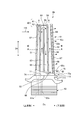
- FIG. 2 is a rear view showing a cross section of a moving blade as a turbine blade of the first embodiment.
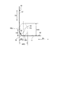
- FIG. 3 is a cross-sectional view showing a moving blade as a turbine blade along the arrow III-III of FIG.
- FIG. 4 is a cross-sectional view of the first fillet portion.
- FIG. 5 is a cross-sectional view of the second fillet portion.
- FIG. 6 is a cross-sectional view of the third fillet portion.
- FIG. 7 is a cross-sectional view showing a modified example of a moving blade as a turbine blade.
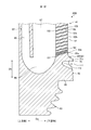
- FIG. 8 is a cross-sectional view showing a moving blade as a turbine blade of the second embodiment.
- FIG. 9 is a cross-sectional view of the turbine blade around the blade base end along the IX-IX arrow view of FIG.
- FIG. 10 is an enlarged view of a main part
- FIG. 1 is a schematic view showing the overall configuration of the gas turbine of the first embodiment.
- the direction in which the central axis O extends is defined as the axial direction Da
- the radial direction of the rotor orthogonal to the central axis O of the rotor is the blade height direction Dh.
- the circumferential direction centered on the central axis O of the rotor will be described as the circumferential direction Dc.
- the gas turbine 10 includes a compressor 11, a combustor 12, and a turbine 13.
- a generator (not shown) is coaxially connected to the gas turbine 10, and the generator can generate electricity.
- the compressor 11 has an air intake port 20 for taking in air, an inlet guide blade (IGV: Inlet Guide Vane) 22 is arranged in the compressor cabin 21, and a plurality of stationary blades 23 and moving blades 24 are provided.
- the air extraction chambers 25 are provided alternately in the axial direction Da and outside the air extraction chambers 25.
- the combustor 12 can burn by supplying fuel to the compressed air compressed by the compressor 11 and igniting it.
- a plurality of stationary blades 27 and moving blades 28 are alternately arranged in the turbine casing 26 in the axial direction Da.
- the turbine casing 26 is provided with an exhaust chamber 30 on the downstream side via an exhaust casing 29, and the exhaust chamber 30 has an exhaust diffuser 31 continuous with the turbine 13.
- the rotor 32 is located so as to penetrate the central portion of the compressor 11, the combustor 12, the turbine 13, and the exhaust chamber 30.
- the end of the rotor 32 on the compressor 11 side is rotatably supported by the bearing portion 33, and the end on the exhaust chamber 30 side is rotatably supported by the bearing portion 34.
- the rotor 32 is compressed by stacking and fixing a plurality of disks on which the rotor blades 24 are mounted on the compressor 11 and stacking and fixing a plurality of disks on which the rotor blades 28 are mounted on the turbine 13.
- a drive shaft of a generator (not shown) is connected to the end on the machine 11 side.
- the compressor casing 21 of the compressor 11 is supported by the legs 35
- the turbine casing 26 of the turbine 13 is supported by the legs 36
- the exhaust chamber 30 is supported by the legs 37.
- the air taken in from the air intake 20 of the compressor 11 passes through the inlet guide blade 22, the plurality of stationary blades 23, and the moving blade 24 and is compressed to become high-temperature and high-pressure compressed air.
- a predetermined fuel is supplied to the compressed air and combusted.
- High-temperature, high-pressure combustion gas which is a working fluid generated by the combustor 12, passes through a plurality of stationary blades 27 and moving blades 28 constituting the turbine 13 to drive and rotate the rotor 32, and is connected to the rotor 32. Drive the generator.
- the combustion gas that drives the turbine 13 is released to the atmosphere as exhaust gas.
- FIG. 2 is a rear view showing a cross section of a moving blade as a turbine blade of the first embodiment
- FIG. 3 is a cross-sectional view showing a moving blade as a turbine blade along the line III-III of FIG. Is a cross-sectional view of the first fillet portion
- FIG. 5 is a cross-sectional view of the second fillet portion
- FIG. 6 is a cross-sectional view of the third fillet portion.
- the moving blade 28 which is a turbine blade, includes a blade shape portion 41, a platform 42 as a blade base end portion, and a blade root portion 43.
- the airfoil portion 41 is arranged along the blade height direction Dh, the blade base end portion 55 portion side is connected to the upper surface 71 of the platform 42, and is integrally formed with the platform 42.
- the wing root portion 43 is fixed to the rotor 32 (see FIG. 1). Therefore, the moving blade 28 rotates together with the rotor 32.
- the airfoil portion 41 includes a blade surface 57 composed of a dorsal airfoil surface 53 having a convex shape on the negative pressure surface side extending in the airfoil height direction Dh, and a ventral airfoil surface 54 having a concave surface shape on the airfoil surface side. It is integrally formed with the top plate 59 formed on the blade tip 56 side in the height direction Dh.
- the airfoil portion 41 has a hollow shape, and the dorsal wing surface 53 and the ventral wing surface 54 are connected on the upstream side in the flow direction of the combustion gas FG along the axial direction Da to form a front edge 51, and are connected on the downstream side.
- the trailing edge 52 is formed, and the trailing edge end face 52Aa is formed on the trailing edge downstream end face.
- the airfoil portion 41 has a tapered shape from the blade base end portion 55 toward the blade tip portion 56, and is joined to the top plate 59 on the blade tip portion 56 side in the blade height direction Dh.
- the airfoil portion 41 is provided with a cooling air passage 60 inside.
- the cooling air passage 60 has a first cooling air passage 61, a second cooling air passage 62, a first supply passage 61a, and a second supply passage 62a.
- the first cooling air passage 61 is provided on the front edge 51 side of the airfoil portion 41 along the blade height direction Dh, is connected to the first supply passage 61a on the blade base end 55 side, and is on the blade tip 56 side. It is open to the top plate 59.
- the first supply passage 61a and the second supply passage 62a are formed in the wing root portion 43 and receive cooling air from the outside.
- the first cooling air passage 61 is formed on the top plate 59 on the blade tip 56 side by allowing the cooling air supplied from the first supply passage 61a to flow in one direction of the blade height direction Dh along the front edge 51. It is discharged from the opening into the external combustion gas FG.
- the second cooling air passage 62 is connected to the second supply passage 62a on the blade base end 55 side, and cooling air is supplied from the second supply passage 62a.
- the second cooling air passage 62 is formed as a meandering passage (serpentine passage) inside the airfoil portion 41, and is provided on the trailing edge 52 side adjacent to the first cooling air passage 61.
- the second cooling air passage 62 has a first passage 63, a first turn-back passage 64, a second passage 65, a second turn-back passage 66, and a third passage 67.
- the first passage 63, the second passage 65, and the third passage 67 are provided along the blade height direction Dh, and the blade tip 56 side of the third passage 67 is connected to the opening formed in the top plate 59.
- the cooling air supplied from the second supply passage 62a flows in the order of the first passage 63, the first turn-back passage 64, the second passage 65, the second turn-back passage 66, and the third passage 67.
- the air is discharged to the outside through the opening formed in the top plate 59 of the blade tip 56.
- the inner wall of the airfoil portion 41 is convected-cooled by the cooling air flowing through the first cooling air passage 61 and the second cooling air passage 62.
- the airfoil portion 41 is provided with a plurality of cooling holes 68 in the blade trailing edge portion 52b on the trailing edge 52 side.
- the plurality of cooling holes 68 are arranged at predetermined intervals in the blade height direction Dh.
- the plurality of cooling holes 68 have one end 102 (see FIG. 9) which is an upstream end in the cooling air flow direction, communicate with the third passage 67, and the other end 103 (FIG. 9) which is a downstream end in the cooling air flow direction. (See), an opening is made in the trailing edge end surface 52a of the trailing edge 52.
- the cooling air flows through the cooling holes 68 formed in the trailing edge portion 52b of the blade, so that the trailing edge portion 52b of the blade is convected-cooled.
- the platform 42 is provided with a first cooling passage 72 on the dorsal wing surface 53 side of the airfoil portion 41 and a second cooling passage 73 on the ventral wing surface 54 side.
- the first cooling passage 72 and the second cooling passage 73 extend from the front edge portion 74 of the platform 42 toward the trailing edge portion 75 in the axial direction Da along the upper surface 71 of the platform 42.
- the upstream end in the cooling air flow direction communicates with the second cooling air passage 62 of the airfoil portion 41, and the downstream end in the cooling air flow direction opens to the trailing edge end surface 75a.
- the upstream end in the cooling air flow direction communicates with the second cooling air passage 62 of the airfoil portion 41, and the downstream end in the cooling air flow direction opens to the trailing edge end surface 75a.
- the first cooling passage 72 and the second cooling passage 73 receive a part of cooling air from the first cooling air passage 61 and the second cooling air passage 62 of the blade-shaped portion 41, and receive a part of the cooling air from the dorsal end portion 44 and the antinode of the platform 42.
- the side end portion 45 is convected-cooled.
- the upstream end to which the first cooling passage 72 is connected may be the first cooling air passage 61
- the upstream end to which the second cooling passage 73 is connected may be the second cooling air passage 62. ..
- the platform 42 is provided with a slime portion 111 at the trailing edge portion 75 in order to suppress the thermal stress generated in the platform 42.
- the slime portion 111 is formed on the trailing edge portion end surface 75a of the trailing edge portion 75 of the platform 42, and is provided so as to be recessed toward the front edge 51 side. That is, the slime portion 111 is formed toward the trailing edge portion end surface 75a of the platform 42 with the front edge side end portion 112 forming a part of the slime portion 111 as the most upstream end portion in the axial direction Da, and is formed toward the trailing edge. It opens at the end face 75a.
- the front edge side end 112 of the slime portion 111 is provided along the circumferential direction Dc from the dorsal end 44 side of the platform 42 toward the ventral end 45 side. Therefore, the opening of the slime portion is formed from the dorsal end 44 side to the ventral end 45 of the trailing edge end surface 75a of the platform 42, and is a part of the dorsal end 44 side and the ventral end 45. It is formed in the range from the trailing edge end surface 75a to the connection position with the front edge side end 112 on the upstream side in the axial direction Da.
- the fillet portion 80 is provided on the entire circumference of the blade surface 57 of the airfoil portion 41.
- the fillet portion 80 has a first fillet portion 81, a second fillet portion 82, and a third fillet portion 83.
- the shapes of the first fillet portion 81, the second fillet portion 82, and the third fillet portion 83 shown in FIGS. 4 to 6 are cross-sectional shapes obtained by looking at each fillet along the blade surface 57 of the airfoil portion 41.
- the first fillet portion 81 is on the dorsal wing surface 53 side of the airfoil portion 41, and the distance between the dorsal wing surface 53 of the airfoil portion 41 and the dorsal end portion 44 of the platform 42 is the shortest and the narrowest position X. It is provided on the trailing edge 75 side of the platform 42.
- the first fillet portion 81 is provided on the trailing edge portion 75 side of the throat portion 110, which will be described later, formed between the blade-shaped portions 41 of the moving blade 28 adjacent to the circumferential direction Dc.
- the fillet width W1 of the first fillet portion 81 is set to be larger than the fillet width W of the region of the fillet portion 80 other than the first fillet portion 81.
- the throat portion is a position that determines the minimum flow path width in the flow direction of the combustion gas FG between the moving blades 28 adjacent to the circumferential direction Dc.
- the tip of the fillet portion 80 formed on the upper surface 71 of the platform 42 in the fillet width W direction of the fillet portion 80 forms a lower outer edge 80b, and a fillet formed in the blade height direction Dh along the blade surface 57.
- the tip of the portion 80 forms an upper outer edge 80a.
- the fillet width W is the length or distance between the connecting portion 76 where the airfoil portion 41 and the upper surface 71 of the platform 42 are joined and the lower outer edge 80b of the fillet portion 80.
- the fillet height H is the length or height between the connecting portion 76 where the airfoil portion 41 and the upper surface 71 of the platform 42 are joined and the upper outer edge 80a of the fillet portion 80.
- the throat portion 110 draws a perpendicular throat line SL perpendicular to the dorsal wing surface 53 of the moving blade 28 from the position of the trailing edge 52 of the airfoil portion 41 of the adjacent moving blade 28, and reaches the dorsal wing surface 53. It refers to the position on the intersecting dorsal blade surface 53.
- the first end portion 81a which is closest to the front edge 51 side forming the first fillet portion 81, is formed on the trailing edge 52 side from the position of the throat portion 110.
- the second fillet portion 82 is provided on the trailing edge 52 side of the first fillet portion 81.
- the second fillet portion 82 is formed on the trailing edge end surface 52a of the airfoil portion 41, and is adjacent to a plurality of cooling holes 68 (see FIG. 2) arranged in the blade height direction Dh and the blade in the blade height direction Dh. It is formed on the base end portion 55 side and is provided at the connecting portion 76 between the airfoil portion 41 and the platform 42.
- the fillet height H of the second fillet portion 82 is set to be smaller than the fillet height H of the fillet portion 80 in a region other than the second fillet portion 82.
- the third fillet portion 83 is provided so as to extend from the front edge 51 to the first fillet portion 81 on the dorsal wing surface 53 side with the front edge 51 of the airfoil portion 41 interposed therebetween, and from the front edge 51 to the ventral wing surface. It extends along 54 to the third fillet changing portion 86, which will be described later.
- the first fillet portion 81 is provided in the region A1 along the blade surface 57 on the dorsal side blade surface 53 side of the airfoil portion 41.
- the first fillet portion 81 is formed by a fillet width W1 and a fillet height H1.
- the cross section of the fillet portion 80 is formed in a perfect circle or an elliptical shape, circumscribes the blade surface 57 and the upper surface 71 of the platform 42, and the position on the circumscribed blade surface 57 corresponds to the upper outer edge 80a and circumscribes.
- the position on the upper surface 71 of the platform 42 corresponds to the lower outer edge 80b.
- the fillet portion 80 is formed by a curved portion (curved concave surface) that smoothly connects the blade surface 57 of the airfoil portion 41 and the upper surface 71 of the platform 42.
- the fillet width W1 of the first fillet portion 81 is the length of the fillet portion 80 in the direction along the upper surface 71 of the platform 42 in the direction orthogonal to the blade surface 57 of the airfoil portion 41.
- the fillet height H1 is the length of the fillet portion 80 in the blade height Dh direction along the blade surface 57 in the direction orthogonal to the upper surface 71 of the platform 42.
- the first fillet portion 81 is formed in a connecting portion 76 connecting the blade surface 57 of the airfoil portion 41 and the upper surface 71 of the platform 42, and the cross-sectional shape of the first fillet portion 81 is an arc shape of a perfect circle R1 and is front. It is continuously formed along the dorsal wing surface 53 in the direction from the edge 51 side to the trailing edge 52. Therefore, the fillet width W1 of the first fillet portion 81 is approximately 1/2 (radius) of WR1, which is the length (diameter) of the fillet width W in the perfect circle R1, and the fillet height H1 is the perfect circle R1. The length (diameter) in the fillet height direction of HR1 is approximately 1/2 (radius).
- the second fillet portion 82 is formed on the trailing edge end surface 52a of the airfoil portion 41, and has a constant width in the circumferential direction in the region A2 along the trailing edge end face 52a of the airfoil surface 57. Is formed in.
- the second fillet portion 82 has a fillet width W2 and a fillet height H2.
- the second fillet portion 82 is formed in a connecting portion 76 connecting the blade surface 57 of the airfoil portion 41 and the upper surface 71 of the platform 42, and the shape of the second fillet portion 82 has a major axis in the blade height direction Dh.
- the elliptical shape of the ellipse R2 having a minor axis in the direction along the upper surface 71 of the platform 42 is continuously formed along the trailing edge end surface 52a. Therefore, the fillet width W2 is approximately 1/2 of the length (minor axis) WR2 in the fillet width direction in the ellipse R2, and the fillet height H2 is the length (major axis) HR2 in the fillet height direction in the ellipse R2. It is about 1/2.
- the tip of the second fillet portion 82 formed on the upper surface of the platform 42 in the fillet width W direction of the second fillet portion 82 forms a lower outer edge 80b, and is located at the position of the fillet width W2 from the blade surface 57 in FIG. Equivalent to. Further, the tip of the second fillet portion 82 formed along the blade surface 57 in the blade height direction Dh forms an upper outer edge 80a, which corresponds to the position of the fillet height H2 from the upper surface 71 of the platform 42 in FIG. To do. Further, the fillet height H2 of the second fillet portion 82 is lower than the fillet height H of the fillet portion 80 in the other region, and the fillet height H of the second fillet portion 82 is formed to be the lowest.
- the third fillet portion 83 is provided in the region A3 along the blade surface 57 on the dorsal blade surface 53 side and the ventral blade surface 54 side of the airfoil portion 41.
- the third fillet portion 83 has a fillet width W3 and a fillet height H3.
- the third fillet portion 83 is formed at a connecting portion 76 connecting the blade surface 57 of the airfoil portion 41 and the upper surface 71 of the platform 42.
- the shape of the third fillet portion 83 is continuously formed by an elliptical shape of an ellipse R3 having a major axis in the blade height direction Dh and a minor axis in the direction along the upper surface 71 of the platform 42.
- the fillet width W3 is approximately 1/2 of the length (minor axis) WR3 in the fillet width direction in the ellipse R3, and the fillet height H3 is the length (major axis) HR3 in the fillet height direction in the ellipse R3. It is about 1/2.
- the tip of the third fillet portion 83 formed on the upper surface 71 of the platform 42 in the fillet width W direction of the third fillet portion 83 forms a lower outer edge 80b, and the position of the fillet width W3 from the blade surface 57 in FIG. Corresponds to.
- the position of the tip of the third fillet portion 83 formed along the blade surface 57 in the blade height direction Dh forms the upper outer edge 80a, and the position of the fillet height H3 from the upper surface 71 of the platform 42 in FIG. Corresponds to. Since the fillet width W and the fillet height H of the first fillet portion 81, the second fillet portion 82, and the third fillet portion 83 are different from each other, there is a second space between the first fillet portion 81 and the second fillet portion 82.
- the fillet changing section 87 (first fillet changing section 84, second) that smoothly connects each fillet section.
- the fillet changing portion 85 and the third fillet changing portion 86) are arranged.
- the aspect ratio of the fillet height H1 to the fillet width W1 is a region other than the first fillet portion 81. It is set smaller than the aspect ratio of the fillet portion 80 of. That is, the first fillet portion 81 has an aspect ratio of 1.0 because the fillet width W1 and the fillet height H1 are the same length.
- the aspect ratio of the first fillet portion 81 is not limited to 1.0, and may be smaller than the aspect ratio of the fillet portion 80 in other regions other than the first fillet portion 81.
- the second fillet portion 82 has a larger aspect ratio than 1.0 because the fillet height H2 is larger than the fillet width W2.
- the third fillet portion 83 has an aspect ratio larger than 1.0 because the fillet height H3 is larger than the fillet width W3. Therefore, the aspect ratio of the first fillet portion 81 is smaller than the aspect ratio of the second fillet portion 82 and the aspect ratio of the third fillet portion 83.
- the first fillet portion 81 has a region A1 in which the aspect ratio maintains a constant ratio along the blade surface 57 of the fillet portion 80.
- the second fillet portion 82 has a region A2 in which the aspect ratio maintains a constant ratio along the blade surface 57 of the trailing edge end surface 52a of the airfoil portion 41.
- the third fillet portion 83 has a region A3 in which the aspect ratio maintains a constant ratio along the blade surface 57 of the fillet portion 80.
- the first fillet portion 81 is provided on the front edge 51 side of the airfoil portion 41 along the blade surface 57 of the fillet portion 80 on the dorsal side blade surface 53 side.
- a second end portion 81b provided on the trailing edge 52 side of the dorsal wing surface 53 side of the airfoil portion 41 along the wing surface 57 of the fillet portion 80.
- the first end 81a and the second end 81b are connected to a fillet change portion 87 in which the fillet width W and the fillet height H change along the blade surface 57 of the fillet portion 80.
- the third fillet portion 83 includes a third end portion 83a provided on the first fillet portion 81 side formed on the dorsal wing surface 53 side of the airfoil portion 41 along the wing surface 57 of the fillet portion 80 and a fillet. It has a fourth end portion 83b formed on the trailing edge 52 side on the ventral wing surface 54 side of the airfoil portion 41 along the wing surface 57 of the portion 80.
- the third end 83a and the fourth end 83b are connected to a fillet change portion 87 in which the fillet width W and the fillet height H change along the blade surface 57 of the fillet portion 80.
- the fillet change unit 87 has a first fillet change unit 84, a second fillet change unit 85, and a third fillet change unit 86.
- the first fillet changing portion 84 is formed between the first end portion 81a and the third end portion 83a arranged on the front edge 51 side of the first end portion 81a, and is formed in the region A11 along the dorsal blade surface 53. Provided. In the first fillet changing portion 84, the fillet width W becomes smaller in the direction from the first end portion 81a to the third end portion 83a, and the fillet height H is maintained at a constant height.
- the fillet width W becomes smaller from the first fillet portion 81 through the first fillet changing portion 84 to the third end portion 83a of the third fillet portion 83, but the fillet height H becomes a constant height. Be maintained.
- the second fillet changing portion 85 is formed between the second end portion 81b and the second fillet portion 82, and is provided in the region A12 along the dorsal wing surface 53.
- the fillet width W and the fillet height H decrease from the second end portion 81b toward the second fillet portion 82.
- the third fillet changing portion 86 is formed between the fourth end portion 83b and the second fillet portion 82, and is provided in the region A13 along the ventral wing surface 54.
- the fillet width W is maintained at a constant width from the fourth end portion 83b toward the second fillet portion 82, and the fillet height H becomes smaller.
- the first fillet portion 81 is provided along the final passage 70 on the most downstream side in the flow direction of the cooling air in the second cooling air passage 62, that is, along the blade wall 58 of the third passage 67.
- the first fillet portion 81 is provided along the final passage 70 on the most downstream side in the flow direction of the cooling air in the second cooling air passage 62, that is, along the passage cross section extending in the cord direction of the third passage 67. ..
- the length of the region A1 in the first fillet portion 81 is included in the range of the length in the cord direction of the passage cross section of the third passage 67.
- the second cooling air passage 62 formed in the airfoil portion 41 is formed from the first passage 63, the first turn-back passage 64, the second passage 65, the second turn-back passage 66, and the third passage 67. Form a meandering passage. Therefore, the cooling air flowing through the second cooling air passage 62 is overheated in the process of flowing in the cooling air passage 60, and the temperature of the cooling air flowing through the final passage 70 becomes high, so that the trailing edge forming the final passage 70 is formed. The metal temperature of the blade wall 58 on the 52 side tends to increase.
- the first fillet portion 81 is formed on the dorsal wing surface 53 side of the airfoil portion 41.
- the dorsal region on the axially downstream side of the trailing edge 75 of the platform 42 surrounded by the dorsal wing surface 53 of the airfoil 41, the dorsal end 44 of the platform 42, and the trailing edge end face 75a is the above-mentioned first. 1
- Cooling passages 72 are only arranged along the dorsal end 44 from the front edge 51 to the trailing edge 52. Therefore, the dorsal region on the axially downstream side of the trailing edge portion 75 of the platform 42, excluding the region where the first cooling passage 72 is arranged, is in an uncooled state.
- the final passage 70 (third passage 67) of the second cooling air passage 62 of the airfoil portion 41 is the airfoil base end portion 55 of the airfoil portion 41 due to the interaction between overheating by cooling air and centrifugal force.
- the thermal stress generated on the side and the thermal stress generated due to the difference in thermal elongation due to the presence of the uncooled region of the platform 42 overlap, and the first fillet near the axial downstream region on the dorsal airfoil surface 53 side of the airfoil portion 41 overlaps.
- the portion 81 tends to generate a higher thermal stress than the fillet portion 80 in the other region.
- the 4 is formed of a circular concave curved surface, and has a concave curved surface shape in which the aspect ratio, which is the ratio of the fillet height H1 and the fillet width W1, is 1.0. It has the smallest aspect ratio than the other fillet portions 80.
- the second fillet portion 82 is formed on the trailing edge end surface 52a of the airfoil portion 41.
- a plurality of cooling holes 68 arranged in the blade height direction are arranged in the blade trailing edge portion 52b and are opened in the trailing edge end surface 52a.
- forming the cooling hole 68 through the second fillet portion 82 is a viewpoint of stress concentration generated around the cooling hole 68. Is not desirable.
- the fillet portion 80 of the wing trailing edge portion 52b is the fillet portion 80 including the second fillet portion 82. It is desirable to arrange the fillet portion 80 as close to the upper outer edge 80a as possible in a processable range in order to cool the fillet portion 80. Therefore, the second fillet portion 82 formed on the trailing edge end surface 52a has the lowest fillet height H2 as compared with the fillet portion 80 in other regions, and is in the blade height direction of the opening 68a of the cooling hole 68.
- the position of Dh is arranged so as to be close to the upper outer edge 80a of the second fillet portion 82 and to the upper surface 71 of the axially downstream side region of the platform 42.
- the third fillet portion 83 is formed on the dorsal wing surface 53 side and the ventral wing surface 54 with the front edge 51 of the airfoil portion 41 interposed therebetween. As shown in FIG. 6, the cross-sectional shape of the third fillet portion 83 is larger at the fillet height H3 than at the fillet width W3, and the aspect ratio, which is the ratio of the fillet height H3 and the fillet width W3, exceeds 1.0. , Is formed as an elliptical fillet long in the wing height direction Dh.
- connection portion 76 between the platform 42 on which the third fillet portion 83 is formed and the airfoil portion 41 does not generate as high thermal stress as the axially downstream region of the platform 42 on which the first fillet portion 81 is formed. Therefore, in consideration of the advantage that a larger aspect ratio is obtained from the viewpoint of aerodynamic performance, the fillet width W of the third fillet portion 83 does not change the fillet height H as compared with the first fillet portion.
- the fillet shape is selected so that the aspect ratio becomes larger than 1 by reducing the size.
- the fillet height H and the fillet width W do not change, and the height H and the fillet are constant.
- the fillet changing portion 87 arranged in the middle connecting the respective fillet portions 80 is formed so as to gradually change the fillet height H or the fillet width W to smoothly connect the fillets. .. It is not desirable to suddenly change the shape of the fillet at each connection point (first end 81a, second end 81b, third end 83a, fourth end 83b) from the viewpoint of aerodynamic performance and stress concentration. Is.
- FIG. 7 is a cross-sectional view showing a modified example of a moving blade as a turbine blade.
- the moving blade 28A of the modified example differs from the first embodiment of the moving blade 28 shown in FIGS. 2 to 6 described above in the configuration of the cooling air passage of the airfoil portion 41.
- Other configurations are the same.
- the rotor blade 28A includes an airfoil portion 41, a platform 42, and a blade root portion 43 (see FIG. 2).
- the airfoil portion 41 is provided with a cooling air passage 90 inside.
- the cooling air passage 90 has a first cooling air passage 91 and a second cooling air passage 92.
- the first cooling air passage 91 is provided on the front edge 51 side of the airfoil portion 41 along the blade height direction Dh, and opens to the top plate 59 on the blade tip 56 side.
- the cooling air supplied to the blade root portion 43 side flows in one direction along the front edge 51, and the external combustion gas FG is formed from the opening formed in the top plate 59 on the blade tip portion 56 side. Discharge inside.
- the second cooling air passage 92 is formed as a meandering passage (serpentine passage) inside the airfoil portion 41, and is adjacent to the first cooling air passage 91. It is provided on the edge 52 side.
- the second cooling air passage 92 includes a first passage 93, a first turn-back passage (not shown), a second passage 94, a second turn-back passage (not shown), a third passage 95, and a third turn-back passage (not shown). , A fourth passage 96, a fourth turn-back passage (not shown), and a fifth passage 97.
- the first passage 93, the second passage 94, the third passage 95, the fourth passage 96, and the fifth passage 97 are provided along the wing height direction Dh, and the wing tip 56 side portion of the fifth passage 97 is a top plate. It is connected to the opening formed in 59.
- the cooling air supplied to the wing root portion 43 side is the first passage 93, the first turn-back passage, the second passage 94, the second turn-back passage, the third passage 95, the third turn-back passage, and the second.
- the four passages 96, the fourth folded passage, and the fifth passage 97 flow in this order, and are discharged to the outside through an opening formed in the top plate 59 of the wing tip 56.
- the fifth passage 97 is also the final passage 70 of the second cooling air passage 92.
- a fillet portion 80 is provided on the entire circumference along the blade surface 57 of the airfoil portion 41 in order to avoid stress concentration of the connecting portion 76 between the airfoil portion 41 and the platform 42. Similar to the moving blade 28 shown in the first embodiment, the fillet portion 80 has a first fillet portion 81, a second fillet portion 82, and a third fillet portion 83. Then, as the fillet change unit, a first fillet change unit 84, a second fillet change unit 85, and a third fillet change unit 86 are provided. Since the configurations of the fillet portion 80 and the fillet changing portion 87 are the same as the configurations of the first embodiment described above, the description thereof will be omitted.
- the airfoil portion 41 having the cooling air passage 60 inside and the platform provided at the blade base end portion 55 in the blade height direction Dh of the airfoil portion 41 ( A blade base end portion) 42 and a fillet portion 80 provided on the entire circumference along the blade surface 57 of the connecting portion 76 between the airfoil portion 41 and the platform 42 are provided.
- the fillet portion 80 is on the dorsal wing surface 53 side of the airfoil portion 41, and is behind the position X where the distance between the dorsal wing surface 53 of the airfoil portion 41 and the dorsal end portion 44 of the platform 42 is the shortest and the distance is narrowest. It has a first fillet portion 81 provided on the edge 52 side and having a fillet width W larger than the fillet width W of another region in the fillet portion 80.
- the thermal stress in the fillet portion 80 can be reduced.
- the first fillet portion 81 on the trailing edge 52 side of the dorsal wing surface 53 side of the platform 42 is located downstream of the position of the throat portion 110 in the axial direction Da as compared with the third fillet portion 83 on the front edge 51 side. Since it is arranged, the influence of the fillet shape on the aerodynamic performance is small. Therefore, the first fillet portion 81 can select a fillet having a larger fillet width W than the third fillet portion 83.
- the first fillet portion 81 is provided on the trailing edge 52 side of the throat portion 110 formed between the adjacent airfoil portions 41. As a result, while the thermal stress in the fillet portion 80 can be reduced, the deterioration of the aerodynamic performance can be suppressed even if the fillet width W is increased.
- the aspect ratio of the fillet height H to the fillet width W of the first fillet portion 81 is smaller than the aspect ratio of the other fillet portions. Therefore, since the first fillet portion 81 has a larger fillet width W than the other fillet portions, it is possible to reduce the generation of thermal stress due to the difference in thermal elongation in the fillet portion 80.
- the first fillet portion 81 is a region in which the aspect ratio maintains a constant ratio along the blade surface 57 of the fillet portion 80. Therefore, the thermal stress can be reduced in a predetermined region (region A1) along the blade surface 57 of the fillet portion 80.
- the aspect ratio of the first fillet portion 81 is 1.0. Therefore, the thermal stress of the first fillet portion 81 can be reduced.
- the first fillet portion 81 is the first end portion 81a provided on the front edge 51 side of the airfoil portion 41 along the blade surface 57 of the fillet portion 80, and the blade of the fillet portion 80. It has a second end 81b provided on the trailing edge 52 side of the airfoil 41 along the surface 57.
- the fillet width W or the fillet height H changes along the blade surface 57 of the fillet portion 80 in another region. Connected to.
- the first fillet portion 81 and the other fillet portions 80 are connected via the fillet changing portions 84 and 85 in which the fillet width W or the fillet height H changes. Therefore, the fillet portion 80 that smoothly connects the blade-shaped portion 41 and the platform 42 is provided, and the deterioration of aerodynamic performance and the stress concentration can be suppressed.
- the airfoil portion 41 is arranged with a plurality of cooling holes 68 arranged at predetermined intervals in the blade height direction Dh of the blade trailing edge portion 52b on the trailing edge 52 side.
- One end of the cooling hole 68 communicates with the cooling air passage 60, and the other end opens to the trailing edge end surface 52a of the trailing edge 52.
- the fillet portion 80 has a second fillet portion 82 in which the fillet height H is smaller than the fillet height H of the other fillet portions 80.
- the second fillet portion 82 is provided on the trailing edge end surface 52a so as to approach and be adjacent to the platform 42 side from the cooling hole 68 in the blade height direction Dh.
- the cooling air flowing through the cooling hole 68 causes the trailing edge portion 52b of the wing including the second fillet portion 82 to have a fillet height H.
- the area on the downstream side in the axial direction on the trailing edge 52 side of the fillet portion 80 and the platform 42 can be efficiently cooled, and the thermal stress of the fillet portion 80 of the blade trailing edge portion 52b including the second fillet portion 82 is reduced. be able to.
- the fillet portion 80 starts from the front edge 51 of the airfoil portion 41, and the dorsal blade surface 53 side is the third fillet portion 83, the first fillet changing portion 84, and the first fillet portion. It extends to the second fillet portion 82 via the 81 and the second fillet changing portion 85.
- the ventral wing surface 54 side extends to the second fillet portion 82 via the third fillet portion 83 and the third fillet changing portion 86. Therefore, a fillet portion 80 having an appropriate shape can be provided on the entire circumference of the connection portion between the airfoil portion 41 and the platform 42.
- the third fillet portion 83 maintains a constant ratio of the aspect ratio of the fillet height H to the fillet width W along the blade surface 57 of the fillet portion 80. Therefore, it is possible to reduce the thermal stress while suppressing the deterioration of the aerodynamic performance in a predetermined region on the blade surface 57 of the fillet portion 80.
- the first fillet changing portion 84 is provided between the first end portion 81a and the third end portion 83a.
- the fillet width W becomes smaller from the first end portion 81a toward the third end portion 83a, and the fillet height H is maintained constant.
- the shape of the first fillet changing portion 84 is an elliptical shape having an aspect ratio of more than 1.0. Therefore, the first fillet portion 81 and the third fillet portion 83 can be smoothly connected by the first fillet changing portion 84, and the fillet width W can be made smaller than that of the first fillet portion 81, resulting in a decrease in aerodynamic performance and stress concentration. Can be suppressed.
- the second fillet changing portion 85 is provided between the second end portion 81b and the second fillet portion 82.
- the fillet width W and the fillet height H decrease from the second end portion 81b toward the second fillet portion 82.
- the change rate of the fillet width W is larger than the change rate of the fillet height H.
- the shape of the second fillet changing portion 85 is an elliptical shape having an aspect ratio of more than 1.0.
- the first fillet portion 81 and the second fillet portion 82 can be smoothly connected by the second fillet changing portion 85, and the fillet width W can be made smaller than that of the first fillet portion 81, resulting in a decrease in aerodynamic performance and stress concentration. Can be suppressed.
- the third fillet changing portion 86 is provided between the fourth end portion 83b and the second fillet portion 82.
- the fillet width W is maintained at a constant width from the fourth end portion 83b toward the second fillet portion 82, and the fillet height H becomes smaller.
- the shape of the third fillet changing portion 86 is an elliptical shape having an aspect ratio of more than 1.0. Therefore, the second fillet portion 82 and the third fillet portion 83 can be smoothly connected by the third fillet changing portion 86, the fillet height H is reduced, and the position of the cooling hole 68 approaches the upper surface 71 of the platform 42. It is possible to suppress the deterioration of aerodynamic performance and stress concentration.
- the first fillet portion 81 has a blade height along the blade wall 58 of the third passage 67, which is the final passage 70 on the most downstream side in the flow direction of the cooling air in the cooling air passage 60. It is provided in the direction Dh. Therefore, the first fillet portion 81 can be effectively cooled by the cooling air flowing through the third passage 67 in the cooling air passage 60.
- a second cooling air passage 62 as a meandering passage is provided inside the airfoil portion, and the first fillet portion 81 is the most downstream in the flow direction of the cooling air in the second cooling air passage 62. It is provided along the passage cross section extending in the cord direction of the third passage 67, which is the final passage 70 on the side, and the length of the region A1 in the first fillet portion 81 is the range of the length of the third passage 67 in the cord direction. Included in.
- the first fillet portion 81 is appropriately cooled by convection cooling by the cooling air flowing through the third passage 67. can do.
- the first cooling passage 72 which extends from the front edge portion 74 to the trailing edge portion 75 of the platform 42, on the ventral blade surface 54 side and the dorsal blade surface 53 side of the blade shape portion 41.
- Two cooling passages 73 are provided, and the upstream side of the first cooling passage 72 and the second cooling passage 73 in the flow direction of the cooling air is communicated with the cooling air passage 60. Therefore, a part of the cooling air supplied to the airfoil portion 41 is supplied to the first cooling passage 72 and the second cooling passage 73 arranged on the platform 42, the platform 42 is convected cooled, and the platform 42 is efficiently cooled. Can be cooled.
- the turbine blade of the first embodiment is applied to the moving blade 28. Therefore, it is possible to suppress the deterioration of the performance of the moving blade 28, and it is possible to reduce the thermal stress in the fillet portion 80.
- the gas turbine of the first embodiment includes a compressor 11, a combustor 12 that mixes and burns compressed air compressed by the compressor 11 and fuel, and a moving blade 28 as a turbine blade.
- the turbine 13 is provided with a turbine 13 that obtains rotational power from the combustion gas FG generated by the combustor 12. Therefore, it is possible to suppress the deterioration of the performance of the turbine 13, while reducing the thermal stress in the fillet portion 80.
- FIG. 8 is a cross-sectional view showing a moving blade as a turbine blade of the second embodiment
- FIG. 9 is a cross-sectional view of the turbine blade around the blade base end portion along the IX-IX arrow view of FIG. It is an enlarged view of the main part of FIG.
- the members having the same functions as those of the first embodiment described above are designated by the same reference numerals, and detailed description thereof will be omitted.
- the rotor blade 28B has the airfoil portion 41, the platform 42, and the blade root portion 43 (FIG. 8), similarly to the rotor blade 28 of the first embodiment described above. 2) and.
- a fillet portion 80 is provided on the entire circumference along the blade surface 57 of the airfoil portion 41 in order to avoid stress concentration of the connecting portion 76 between the airfoil portion 41 and the platform 42. Similar to the moving blade 28 shown in the first embodiment, the fillet portion 80 has a first fillet portion 81, a second fillet portion 82, and a third fillet portion 83. Then, as the fillet change unit, a first fillet change unit 84, a second fillet change unit 85, and a third fillet change unit 86 are provided. Since the configuration of the fillet portion 80 and the fillet changing portion is the same as the configuration of the first embodiment described above, the description thereof will be omitted.
- the airfoil portion 41 is provided with a plurality of cooling holes 68 in the blade trailing edge portion 52b on the trailing edge 52 side.
- the plurality of cooling holes 68 are arranged at predetermined intervals in the blade height direction Dh, one end communicating with the third passage 67 in the second cooling air passage 62, and the other end with the trailing edge end surface 52a of the trailing edge 52. Open. Further, the cooling hole 68 is arranged at a position close to the platform 42 side on the trailing edge end surface 52a of the airfoil portion 41 and at a position outside the blade height direction Dh adjacent to the upper outer edge 80a of the second fillet portion 82. To. As will be described later, the plurality of cooling holes 68 include a plurality of end cooling holes 101 whose opening densities are larger than the opening densities of the other plurality of cooling holes 68.
- one end 102 on the upstream side communicates with the third passage 67 in the second cooling air passage 62, and the other end 103 on the downstream side has a trailing edge 52. It opens to the trailing edge end face 52a.
- the end cooling hole 101 located on the blade base end 55 (see FIG. 2) side where the second fillet portion 82 is provided is cooled located on the blade tip 56 (see FIG. 2) side of the end cooling hole 101.
- the opening density is larger in the blade height direction Dh. Therefore, by arranging the end cooling hole 101 close to the upper outer edge 80a of the fillet portion 80, a sufficient supply amount of cooling air is secured, and convection cooling of the second fillet portion 82 is more effective. It can be carried out.
- the cooling hole 68 is circular, the wet length S corresponds to the circumferential length.
- the platform 42 is provided with a slime portion 111 at the trailing edge portion 75.
- the slime portion 111 is formed on the trailing edge portion end surface 75a of the platform 42, and is provided so as to be recessed from the trailing edge portion end surface 75a toward the front edge 51 side. That is, the slime portion 111 opens toward the rear edge portion end surface 75a side of the platform 42 with the position of the front edge side end portion 112 forming a part of the slime portion 76111 as the most upstream end portion in the axial direction Da. ..
- the front edge side end 112 of the slime portion 111 is provided along the circumferential direction Dc from the dorsal end 44 side of the platform 42 to the ventral end 45 side.
- the opening of the slime portion 111 is formed from the dorsal end 44 side to the ventral end 45 of the trailing edge end surface 75a of the platform 42, and is one of the dorsal end 44 side and the ventral end 45.
- the portion is formed in a range from the trailing edge portion end surface 75a to the connection position with the front edge side end portion 112 on the upstream side in the axial direction Da.
- the slime portion 111 extends from the ventral end 45 side of the platform 42 to the dorsal end 44 side.
- the front edge side end 112 of the slime portion 111 is formed so as to go from the ventral end 45 side of the platform 42 to the dorsal end 44 side and approach the rear edge end surface 75a of the platform 42. That is, in the slime portion 111, the front edge side end 112 on the front edge 51 side of the platform 42 is the flow direction of the cooling air in the second cooling air passage 62 of the airfoil portion 41 in the plan view (FIG. 8) of the platform 42.
- the final passage 70 on the most downstream side of the airfoil that is, between the end (one end 102) on the trailing edge 52 side of the third passage 67 and the trailing edge end surface 52a of the airfoil portion 41.
- the front edge side end 112 of the slime portion 111 is formed linearly from the ventral end 45 of the platform 42 toward the dorsal end 44, and is inclined with respect to the circumferential direction Dc to the trailing edge end surface 75a. On the other hand, it is formed at an angle. Since the front edge side end portion 112 of the slime portion 111 is formed in a straight line, processing is easy.
- the rigidity of the trailing edge portion 75 of the platform is reduced, which is significant.
- the thermal stress of the trailing edge portion 75 and the fillet portion 80 of the platform can be reduced.
- the front edge 51 side as the front edge side end 112 of the slime portion 111 moves from the dorsal end 44 side to the ventral end 45 side. It is provided so as to be inclined with respect to the width direction (circumferential direction Dc) of the platform 42 so as to approach. Therefore, in the vicinity of the connecting portion 76 (second fillet portion 82) between the trailing edge end surface 52a of the airfoil portion 41 and the platform 42, where stress reduction is highly necessary, the sewn portion 111 is sufficiently deep in the direction toward the front edge 51 side. It can be formed, whereby the thermal stress at the fillet portion 80 including the second fillet portion 82 and the trailing edge portion 75 of the platform 42 can be reduced.
- turbine blades of the present invention have been described by applying them to the moving blades 28 in the above-described embodiment, they may be applied to the stationary blades 27.
Landscapes
- Engineering & Computer Science (AREA)
- Mechanical Engineering (AREA)
- General Engineering & Computer Science (AREA)
- Physics & Mathematics (AREA)
- Fluid Mechanics (AREA)
- Turbine Rotor Nozzle Sealing (AREA)
Abstract
タービン翼およびガスタービンにおいて、内部に冷却空気通路(60)を有する翼形部(41)と、翼形部(41)の翼高さ方向(Dh)の翼基端部(55)に設けられるプラットフォーム(42)と、翼形部(41)とプラットフォーム(42)との接続部の全周に設けられるフィレット部(80)とを備える。フィレット部(80)は、翼形部(41)の背側翼面(53)側であって、翼形部(41)の背側翼面(53)とプラットフォーム(42)の背側端部(44)との距離が最も短い位置より後縁(52)側に設けられ、フィレット幅(W)がフィレット部(80)における他の領域のフィレット幅Wより大きい第1フィレット部(81)を有する。
Description
本発明は、ガスタービンに適用される動翼や静翼などのタービン翼、このタービン翼を備えたガスタービンに関するものである。
ガスタービンは、圧縮機と燃焼器とタービンを有する。圧縮機は、空気取入口から取り込まれた空気を圧縮することで高温・高圧の圧縮空気とする。燃焼器は、圧縮空気に燃料を供給して燃焼させることで高温・高圧の燃焼ガスを得る。タービンは、燃焼ガスにより駆動し、同軸上に連結された発電機を駆動する。
ガスタービンにおける動翼や静翼などのタービン翼において、タービン翼の内部に冷却通路を設け、冷却通路に冷却流体を流すことにより、高温のガス流れに曝されるタービン翼を冷却することが知られている。例えば、下記特許文献1には、動翼の内部に冷却空気通路を設け、冷却空気が冷却空気通路を通った後に、後縁側の穴から吹出すものが記載されている。また、この動翼において、翼基端部とプラットフォームとの接続部の間に楕円形状をなすフィレット部を設けることにより、熱応力を低減させることが記載されている。
従来、上述したように、動翼などのタービン翼では、翼基端部とプラットフォームとの接続部に熱応力が生じやすい。そのため、翼基端部とプラットフォームとの接続部における熱応力を緩和するため、接続部にフィレット部を形成している。接続部にフィレット部を形成することにより、熱応力を低減させることができる。一方で、タービン翼は、高温のガス流れを受けることから、空気力学的に翼基端部とプラットフォームとの接続部のフィレット部を小さくしたいという要望がある。
本発明は上述した課題を解決するものであり、空力性能の低下を抑制する一方でフィレット部における熱応力を低減するタービン翼およびガスタービンを提供することを目的とする。
上記の目的を達成するための本発明の一実施態様であるタービン翼は、内部に冷却空気通路を有する翼形部と、前記翼形部の翼高さ方向の端部に設けられる翼基端部と、前記翼形部と前記翼基端部との接続部の全周に設けられるフィレット部と、を含み、前記フィレット部は、前記翼形部の背側であって、前記翼形部の背側翼面と前記翼基端部の背側端部との距離が最も短い位置より後縁側に設けられ、フィレット幅が前記フィレット部における他の領域の前記フィレット幅より大きい第1フィレット部を有する。
そのため、フィレット部における翼形部の背側の後縁側の部分は、熱応力を受けやすい。この部分にフィレット幅をフィレット部における他の領域のフィレット幅より大きい第1フィレット部を設けることで、フィレット部における熱応力を低減することができる。
本発明の一実施態様であるタービン翼では、前記第1フィレット部は、隣接する前記翼形部との間のスロート部より後縁側に設けられる。
そのため、フィレット部における熱応力を低減することができる一方で、空力性能の低下面では、影響は小さい。
本発明の一実施態様であるタービン翼では、前記第1フィレット部は、前記フィレット幅に対するフィレット高さの比であるアスペクト比が前記フィレット部における他の領域の前記アスペクト比より小さい。
そのため、第1フィレット部は、他のフィレット部よりも、フィレット幅が大きいことから、フィレット部における熱伸びによる熱応力の発生を低減することができる。
本発明の一実施態様であるタービン翼では、前記第1フィレット部は、前記アスペクト比が前記フィレット部の周方向に沿って一定である領域を有する。
そのため、フィレット部の周方向における所定の領域で、熱応力を低減することができる。
本発明の一実施態様であるタービン翼では、前記第1フィレット部は、前記アスペクト比が1.0である。
そのため、第1フィレット部の熱応力を低減することができる。
本発明の一実施態様であるタービン翼では、前記第1フィレット部は、前記フィレット部の翼面に沿った前記翼形部の前縁側に設けられる第1端部と、前記フィレット部の前記翼面に沿った前記翼形部の後縁側に設けられる第2端部とを有し、前記第1端部および前記第2端部は、前記フィレット幅または前記フィレット高さが前記フィレット部の前記翼面に沿って変化するフィレット変化部に接続される。
そのため、第1フィレット部と他のフィレット部とをフィレット幅またはフィレット高さが変化するフィレット変化部により接続することから、翼形部と翼基端部との接続部に滑らかに連続するフィレット部を設けることとなり、空力性能の低下および急激な熱応力の変化を抑制することができる。
本発明の一実施態様であるタービン翼では、前記翼形部は、後縁部に翼高さ方向に所定間隔を空けて複数配列され、一端が前記冷却空気通路に連通し、他端が前記後縁部の後縁端面に開口する複数の冷却孔を有し、前記フィレット部は、前記冷却孔に接近させて翼高さ方向の内側に隣接して前記後縁端面に設けられ、前記フィレット高さが前記フィレット部における他の領域の前記フィレット高さより小さい第2フィレット部を含む。
そのため、第2フィレット部は、フィレット高さが他のフィレット部のフィレット高さより小さいことから、冷却孔の翼高さ方向の位置が、他の領域よりプラットフォームの上面に接近するので、冷却孔を流れる冷却空気によりプラットフォームの上面が効率良く冷却することができ、プラットフォーム42の後縁部側の熱応力を低減することができる。
本発明の一実施態様であるタービン翼では、前記フィレット部は、前記翼形部の前縁を挟んで背側翼面に沿って前記フィレット変化部を介して前記第1フィレット部に接続し、腹側翼面に沿って前記フィレット変化部を介して前記第2フィレット部に接続する第3フィレット部を含む。
そのため、第1フィレットおよび第2フィレット部に加えて、翼形部の前縁を挟んで背側翼面から腹側翼面にかけて第3フィレット部を設けることから、翼形部と翼基端部との間の全周に適正形状のフィレットを設けることができる。また、フィレット変化部を設けることにより、空力性能の低下を抑制できる。
本発明の一実施態様であるタービン翼では、前記第3フィレット部は、前記フィレット幅に対する前記フィレット高さの前記アスペクト比が前記フィレット部の前記翼面に沿って一定である領域を有する。
そのため、フィレット部の周方向における所定の領域で、熱応力を低減することができる。
本発明の一実施態様であるタービン翼では、前記フィレット変化部は、前記第1端部と前記第3端部との間に設けられる第1フィレット変化部を含み、前記第1フィレット変化部は、前記第1端部から前記第3端部に向かって前記フィレット幅が小さくなり、前記フィレット高さが一定に維持される。
そのため、第1フィレット変化部により第1フィレット部と第3フィレット部を滑らかに接続することができ、空力性能の低下および急激な熱応力の変化を抑制することができる。
本発明の一実施態様であるタービン翼では、前記第1フィレット変化部は、前記フィレット幅に対する前記フィレット高さの前記アスペクト比が1.0より大きい楕円形状のフィレットを有する。
そのため、第1フィレット変化部により第1フィレット部と第3フィレット部を滑らかに接続することができる。
本発明の一実施態様であるタービン翼では、前記フィレット変化部は、前記第2端部と前記第2フィレット部との間に設けられる第2フィレット変化部を含み、前記第2フィレット変化部は、前記第2端部から前記第2フィレット部に向かって前記フィレット幅および前記フィレット高さが小さくなる。
そのため、第2フィレット変化部により第1フィレット部と第2フィレット部を滑らかに接続することができ、空力性能の低下および急激な熱応力の変化を抑制することができる。
本発明の一実施態様であるタービン翼では、前記第2フィレット変化部は、前記フィレット幅に対する前記フィレット高さの前記アスペクト比が1.0より大きい楕円形状のフィレットを有する。
そのため、第2フィレット変化部により第1フィレット部と第2フィレット部を滑らかに接続することができる。
本発明の一実施態様であるタービン翼では、前記フィレット変化部は、前記第4端部と前記第2フィレット部との間に設けられる第3フィレット変化部を含み、前記第3フィレット変化部は、前記第4端部から前記第2フィレット部に向かって前記フィレット幅が一定に維持され、前記フィレット高さが小さくなる。
そのため、第3フィレット変化部により第2フィレット部と第3フィレット部を滑らかに接続することができ、性能の低下を抑制することができる。
本発明の一実施態様であるタービン翼では、前記第3フィレット変化部は、前記フィレット幅に対する前記フィレット高さの前記アスペクト比が1.0より大きい楕円形状のフィレットを有する。
そのため、第3フィレット変化部により第2フィレット部と第3フィレット部を滑らかに接続することができる。
本発明の一実施態様であるタービン翼では、前記複数の冷却孔は、前記翼形部における前記翼基端部側で前記第2フィレット部に隣接する位置に開口密度が他の複数の冷却孔の開口密度より大きい端部冷却孔を含み、前記端部冷却孔は、前記第2フィレット部における翼高さ方向の前記翼形部側に隣接して配置される。
そのため、第2フィレット部に接近させて開口密度の高い冷却孔を配置して第2フィレット部近傍の冷却能力が強化され、第2フィレット部の冷却性能を向上することができる。
本発明の一実施態様であるタービン翼では、前記第1フィレット部は、前記冷却空気通路における冷却空気の流れ方向の最下流側の最終通路の翼壁に沿って設けられる。
そのため、冷却空気通路における最終通路を流れる冷却空気により第1フィレット部を効果的に冷却することができる。
本発明の一実施態様であるタービン翼では、前記冷却空気通路は、前記翼形部の内部に設けられる蛇行通路を有し、前記第1フィレット部は、前記蛇行通路における冷却空気の流れ方向の最下流側の前記最終通路に沿って設けられ、前記第1フィレット部における領域の長さは、前記最終通路のコード方向の長さの範囲に含まれる。
そのため、第1フィレット部における領域の長さより最終通路のコード方向の長さが長いことから、最終通路を流れる冷却空気により第1フィレット部を適正に冷却することができる。
本発明の一実施態様であるタービン翼では、前記翼基端部は、前記翼形部の翼高さ方向に直交する方向に延在するプラットフォームを含み、前記プラットフォームは、前記プラットフォームの後縁部端面に形成され、該後縁部端面から前縁側へ向かって凹むぬすみ部を有し、前記ぬすみ部は、前記プラットフォームの腹側端部から背側端部まで延在し、前記ぬすみ部の前縁側端部が前記プラットフォームの前記腹側端部から前記背側端部に向かって前記プラットフォームの前記後縁部端面に接近するように設けられる。
そのため、ぬすみ部の前縁側端部を翼形部の腹側から背側に向かってプラットフォームの後縁部に接近するように設けることから、ぬすみ部を設けた部分では、プラットフォーム42の剛性が低下するため、翼形部の翼後縁部における応力を低減することができる。
本発明の一実施態様であるタービン翼では、前記ぬすみ部は、前記プラットフォームにおける前記前縁側部が、前記プラットフォームの平面視において、前記冷却空気通路における冷却空気の流れ方向の最下流側の最終通路と前記翼形部の後縁端面の間に位置する。
そのため、ぬすみ部が冷却空気通路における最終通路に接近することで、翼形部の翼後縁部とプラットフォームとの接続部の近傍で、ぬすみ部を十分に深く形成することができる。
本発明の一実施態様であるタービン翼では、前記ぬすみ部は、前記プラットフォームにおける前記前縁側部が、前記プラットフォームの前記腹側端部から前記背側端部に向けて直線状に形成される。
そのため、ぬすみ部の端部が直線状をなすことから、加工性を向上することができる。
本発明の一実施態様であるタービン翼では、前記プラットフォームは、前記翼形部プラットフォームにおける前記背側端部に沿って前縁から後縁に延在する第1冷却通路と、前記プラットフォームにおける前記腹側端部に沿って前縁から後縁に延在する第2冷却通路と、を含み、前記第1冷却通路および前記第2冷却通路は、冷却空気の流れ方向の上流側が前記翼形部の前記冷却空気通路に連通し、下流側が前記後縁部端面で燃焼ガス中に開口する。
そのため、プラットフォームに冷却通路を設け、冷却空気通路に連通することから、翼形部を冷却した冷却空気をプラットフォームに供給し、このプラットフォームを効率良く冷却することができる。
本発明の一実施態様であるタービン翼では、前記タービン翼は、動翼である。
そのため、動翼の性能の低下を抑制することができる一方で、フィレット部における熱応力を低減することができる。
また、本発明のガスタービンは、空気を圧縮する圧縮機と、前記圧縮機が圧縮した圧縮空気と燃料を混合して燃焼する燃焼器と、前記タービン翼を有して前記燃焼器が生成した燃焼ガスにより回転動力を得るタービンと、を備える。
そのため、タービンの性能の低下を抑制することができる一方で、フィレット部における熱応力を低減することができる。
本発明のタービン翼およびガスタービンによれば、空力性能の低下を抑制することができる一方で、フィレット部における熱応力を低減することができる。
以下に図面を参照して、本発明の好適な実施形態を詳細に説明する。なお、この実施形態により本発明が限定されるものではなく、また、実施形態が複数ある場合には、各実施形態を組み合わせて構成するものも含むものである。
[第1実施形態]
図1は、第1実施形態のガスタービンの全体構成を表す概略図である。なお、以下の説明では、ガスタービンのロータの中心軸線をOとしたとき、中心軸線Oが延びる方向を軸方向Daとし、ロータの中心軸線Oに直交するロータの径方向を翼高さ方向Dh、ロータの中心軸線Oを中心とした周方向を周方向Dcとして説明する。
図1は、第1実施形態のガスタービンの全体構成を表す概略図である。なお、以下の説明では、ガスタービンのロータの中心軸線をOとしたとき、中心軸線Oが延びる方向を軸方向Daとし、ロータの中心軸線Oに直交するロータの径方向を翼高さ方向Dh、ロータの中心軸線Oを中心とした周方向を周方向Dcとして説明する。
第1実施形態において、図1に示すように、ガスタービン10は、圧縮機11と燃焼器12とタービン13とを備える。ガスタービン10は、同軸上に図示しない発電機が連結され、発電機により発電が可能である。
圧縮機11は、空気を取り込む空気取入口20を有し、圧縮機車室21内に入口案内翼(IGV:Inlet Guide Vane)22が配設されると共に、複数の静翼23と動翼24が軸方向Daに交互に配設され、その外側に抽気室25が設けられる。燃焼器12は、圧縮機11で圧縮された圧縮空気に対して燃料を供給し、点火することで燃焼可能である。タービン13は、タービン車室26内に複数の静翼27と動翼28が軸方向Daに交互に配設される。タービン車室26は、下流側に排気車室29を介して排気室30が配設され、排気室30は、タービン13に連続する排気ディフューザ31を有する。
また、圧縮機11、燃焼器12、タービン13、排気室30の中心部を貫通するようにロータ32が位置する。ロータ32は、圧縮機11側の端部が軸受部33により回転自在に支持され、排気室30側の端部が軸受部34により回転自在に支持される。ロータ32は、圧縮機11にて、各動翼24が装着されたディスクが複数重ねられて固定され、タービン13にて、各動翼28が装着されたディスクが複数重ねられて固定され、圧縮機11側の端部に発電機(図示略)の駆動軸が連結される。
ガスタービン10は、圧縮機11の圧縮機車室21が脚部35に支持され、タービン13のタービン車室26が脚部36により支持され、排気室30が脚部37により支持される。
そのため、圧縮機11の空気取入口20から取り込まれた空気が、入口案内翼22、複数の静翼23と動翼24を通過して圧縮されることで高温・高圧の圧縮空気となる。燃焼器12にて、圧縮空気に対して所定の燃料が供給され、燃焼する。燃焼器12で生成された作動流体である高温・高圧の燃焼ガスが、タービン13を構成する複数の静翼27と動翼28を通過することでロータ32を駆動回転し、ロータ32に連結された発電機を駆動する。一方、タービン13を駆動した燃焼ガスは、排気ガスとして大気に放出される。
図2は、第1実施形態のタービン翼としての動翼の断面を示した背面図、図3は、図2のIII-III矢視に沿うタービン翼としての動翼を表す断面図、図4は、第1フィレット部の断面図、図5は、第2フィレット部の断面図、図6は、第3フィレット部の断面図である。
図2および図3に示すように、タービン翼である動翼28は、翼形部41と、翼基端部としてのプラットフォーム42と、翼根部43とを備える。翼形部41は、翼高さ方向Dhに沿って配置され、翼基端部55部側がプラットフォーム42の上面71に接続し、プラットフォーム42と共に一体に形成されている。翼根部43は、ロータ32(図1参照)に固定される。そのため、動翼28は、ロータ32と共に回転する。
翼形部41は、翼高さ方向Dhに延在する負圧面側の凸面形状を有する背側翼面53と、圧力面側の凹面形状を有する腹側翼面54とからなる翼面57と、翼高さ方向Dhの翼先端部56側に形成された天板59とにより、一体に形成されている。翼形部41は、中空形状を備え、背側翼面53と腹側翼面54は、軸方向Daに沿う燃焼ガスFGの流れ方向の上流側で接続されて前縁51が形成され、下流側で接続されて後縁52が形成され、後縁下流側端面に後縁端面52Aaが形成されている。翼形部41は、翼基端部55から翼先端部56に向けて先細り形状を備え、翼高さ方向Dhの翼先端部56側で天板59に接合する。
翼形部41は、内部に冷却空気通路60が設けられる。冷却空気通路60は、第1冷却空気通路61と、第2冷却空気通路62と、第1供給通路61aと、第2供給通路62aとを有する。第1冷却空気通路61は、翼形部41の前縁51側に翼高さ方向Dhに沿って設けられ、翼基端部55側で第1供給通路61aに接続し、翼先端部56側で天板59に開口している。第1供給通路61aおよび第2供給通路62aは、翼根部43に形成され、外部から冷却空気を受け入れている。第1冷却空気通路61は、第1供給通路61aから供給された冷却空気を前縁51に沿って翼高さ方向Dhの一方向に流れ、翼先端部56側の天板59に形成された開口から外部の燃焼ガスFG中に排出される。第2冷却空気通路62は、翼基端部55側で第2供給通路62aに接続し、第2供給通路62aから冷却空気が供給されている。第2冷却空気通路62は、翼形部41の内部に蛇行通路(サーペンタイン通路)として形成され、第1冷却空気通路61に隣接して後縁52側に設けられる。第2冷却空気通路62は、第1通路63、第1折り返し通路64、第2通路65、第2折り返し通路66、第3通路67を有する。第1通路63と第2通路65と第3通路67が翼高さ方向Dhに沿って設けられ、第3通路67の翼先端部56側が天板59に形成された開口に接続している。第2冷却空気通路62は、第2供給通路62aから供給された冷却空気が第1通路63、第1折り返し通路64、第2通路65、第2折り返し通路66、第3通路67の順に流れ、翼先端部56の天板59に形成された開口から外部に排出する。冷却空気が、第1冷却空気通路61及び第2冷却空気通路62を流れることにより、翼形部41の内壁が対流冷却される。
また、翼形部41は、後縁52側の翼後縁部52bに複数の冷却孔68が設けられる。複数の冷却孔68は、翼高さ方向Dhに所定間隔を空けて配列されている。複数の冷却孔68は、冷却空気の流れ方向の上流端である一端102(図9参照)で、第3通路67に連通し、冷却空気の流れ方向の下流端である他端103(図9参照)で、後縁52の後縁端面52aに開口する。冷却空気が、翼後縁部52bに形成された冷却孔68を流れることにより、翼後縁部52bが対流冷却される。
プラットフォーム42は、翼形部41における背側翼面53側に第1冷却通路72が設けられ、腹側翼面54側に第2冷却通路73が設けられる。第1冷却通路72と第2冷却通路73は、プラットフォーム42の前縁部74から後縁部75に向かって軸方向Daにプラットフォーム42の上面71に沿って延在する。第1冷却通路72は、冷却空気の流れ方向の上流端が翼形部41の第2冷却空気通路62に連通し、冷却空気の流れ方向の下流端が後縁部端面75aに開口する。第2冷却通路73は、冷却空気の流れ方向の上流端が翼形部41の第2冷却空気通路62に連通し、冷却空気の流れ方向の下流端が後縁部端面75aに開口する。第1冷却通路72及び第2冷却通路73は、翼形部41の第1冷却空気通路61及び第2冷却空気通路62から冷却空気の一部を受け入れ、プラットフォーム42の背側端部44及び腹側端部45を対流冷却している。なお、第1冷却通路72が接続する上流端は、第1冷却空気通路61であってもよいし、第2冷却通路73が接続する上流端は、第2冷却空気通路62であってもよい。
図3、図8及び図9に示すように、プラットフォーム42は、プラットフォーム42に発生する熱応力を抑制するため、後縁部75にぬすみ部111が設けられる。ぬすみ部111は、プラットフォーム42の後縁部75の後縁部端面75aに形成され、前縁51側の方向へ向かって凹むように設けられる。つまり、ぬすみ部111は、ぬすみ部111の一部を形成する前縁側端部112を軸方向Daの最も上流側の端部として、プラットフォーム42の後縁部端面75aに向かって形成され、後縁部端面75aで開口する。ぬすみ部111の前縁側端部112は、プラットフォーム42の背側端部44側から腹側端部45側に向かって周方向Dcに沿って設けられる。従って、ぬすみ部の開口は、プラットフォーム42の後縁部端面75aの背側端部44側から腹側端部45まで形成されると共に、背側端部44側および腹側端部45の一部であって、後縁部端面75aから軸方向Daの上流側の前縁側端部112との接続位置までの範囲に形成される。
また、図3に示すように、動翼28は、翼形部41とプラットフォーム42との接続部76の応力集中を回避するため、翼形部41の翼面57の全周にフィレット部80が設けられる。フィレット部80は、第1フィレット部81と、第2フィレット部82と、第3フィレット部83とを有する。図4から図6に示す第1フィレット部81、第2フィレット部82および第3フィレット部83の形状は、翼形部41の翼面57に沿って各フィレットを見た断面形状である。
第1フィレット部81は、翼形部41の背側翼面53側であって、翼形部41の背側翼面53とプラットフォーム42の背側端部44との距離が最も短く幅の狭い位置Xよりプラットフォーム42の後縁部75側に設けられる。第1フィレット部81は、周方向Dcに隣接する動翼28の翼形部41の間に形成される後述するスロート部110より後縁部75側に設けられる。第1フィレット部81は、フィレット幅W1が第1フィレット部81以外の他のフィレット部80の領域のフィレット幅Wより大きく設定される。ここで、スロート部とは、周方向Dcに隣接する動翼28間において、燃焼ガスFGの流動方向の最小流路幅を定める位置である。なお、フィレット部80のフィレット幅W方向のプラットフォーム42の上面71に形成されるフィレット部80の先端は、下部外縁80bを形成し、翼面57に沿った翼高さ方向Dhに形成されるフィレット部80の先端は、上部外縁80aを形成する。ここで、フィレット幅Wとは、翼形部41とプラットフォーム42の上面71とが接合する接続部76とフィレット部80の下部外縁80bとの間の長さ又は距離である。フィレット高さHとは、翼形部41とプラットフォーム42の上面71とが接合する接続部76とフィレット部80の上部外縁80aとの間の長さ又は高さである。
ここで、スロート部110と第1フィレット部81の位置関係について、図3により説明する。図3において、スロート部110は、隣接する動翼28の翼形部41の後縁52の位置から動翼28の背側翼面53に垂直に垂線スロート線SLを下し、背側翼面53に交わる背側翼面53上の位置を言う。一方、第1フィレット部81を形成する最も前縁51側に近い第1端部81aは、スロート部110の位置より後縁52側に形成されている。
第2フィレット部82は、第1フィレット部81より後縁52側に設けられる。第2フィレット部82は、翼形部41の後縁端面52aに形成され、翼高さ方向Dhに配列された複数の冷却孔68(図2参照)と翼高さ方向Dhに隣接して翼基端部55側に形成され、翼形部41とプラットフォーム42の接続部76に設けられる。第2フィレット部82は、フィレット高さHが第2フィレット部82以外の他の領域のフィレット部80のフィレット高さHより小さく設定される。
第3フィレット部83は、翼形部41の前縁51を挟んで、前縁51から背側翼面53側の第1フィレット部81まで延在して設けられると共に、前縁51から腹側翼面54に沿って後述する第3フィレット変化部86まで延在して設けられる。
図3および図4に示すように、第1フィレット部81は、翼形部41の背側翼面53側の翼面57に沿った領域A1に設けられる。第1フィレット部81は、フィレット幅W1およびフィレット高さH1で形成される。ここで、フィレット部80の断面は、真円または楕円形状に形成され、翼面57およびプラットフォーム42の上面71に外接し、外接する翼面57上の位置が上部外縁80aに相当し、外接するプラットフォーム42の上面71上の位置が、下部外縁80bに相当する。フィレット部80は、翼形部41の翼面57とプラットフォーム42の上面71とを滑らかに接続する湾曲部(湾曲凹面)で形成される。第1フィレット部81のフィレット幅W1とは、翼形部41の翼面57に直交する方向のプラットフォーム42の上面71に沿った方向のフィレット部80の長さである。フィレット高さH1とは、プラットフォーム42の上面71に直交する方向の翼面57に沿った翼高さDh方向のフィレット部80の長さである。第1フィレット部81は、翼形部41の翼面57とプラットフォーム42の上面71とが接続する接続部76に形成され、第1フィレット部81の断面形状は、真円R1の円弧形状で前縁51側から後縁52の方向に背側翼面53に沿って連続して形成されている。そのため、第1フィレット部81のフィレット幅W1は、真円R1におけるフィレット幅W方向の長さ(直径)であるWR1の略1/2(半径)であり、フィレット高さH1は、真円R1におけるフィレット高さ方向の長さ(直径)HR1の略1/2(半径)の長さである。
図3および図5に示すように、第2フィレット部82は、翼形部41の後縁端面52aに形成され、翼面57の後縁端面52aに沿った領域A2に一定の幅で周方向に形成されている。第2フィレット部82は、フィレット幅W2であり、フィレット高さH2である。第2フィレット部82は、翼形部41の翼面57とプラットフォーム42の上面71とが接続する接続部76に形成され、第2フィレット部82の形状は、翼高さ方向Dhが長径であり、プラットフォーム42の上面71に沿う方向が短径である楕円R2の楕円形状で後縁端面52aに沿って連続して形成される。そのため、フィレット幅W2は、楕円R2におけるフィレット幅方向の長さ(短径)WR2の略1/2であり、フィレット高さH2は、楕円R2におけるフィレット高さ方向の長さ(長径)HR2の略1/2である。なお、第2フィレット部82のフィレット幅W方向のプラットフォーム42の上面に形成される第2フィレット部82の先端は、下部外縁80bを形成し、図5における翼面57からフィレット幅W2の位置に相当する。また、翼面57に沿った翼高さ方向Dhに形成される第2フィレット部82の先端は、上部外縁80aを形成し、図5におけるプラットフォーム42の上面71からフィレット高さH2の位置に相当する。また、第2フィレット部82のフィレット高さH2は、他の領域のフィレット部80のフィレット高さHより低く、第2フィレット部82のフィレット高さHが最も低く形成されている。
図3および図6に示すように、第3フィレット部83は、翼形部41の背側翼面53側および腹側翼面54側の翼面57に沿った領域A3に設けられる。第3フィレット部83は、フィレット幅W3であり、フィレット高さH3である。第3フィレット部83は、翼形部41の翼面57とプラットフォーム42の上面71とが接続する接続部76に形成される。第3フィレット部83の形状は、翼高さ方向Dhが長径であり、プラットフォーム42の上面71に沿う方向が短径である楕円R3の楕円形状で連続して形成される。そのため、フィレット幅W3は、楕円R3におけるフィレット幅方向の長さ(短径)WR3の略1/2であり、フィレット高さH3は、楕円R3におけるフィレット高さ方向の長さ(長径)HR3の略1/2である。なお、第3フィレット部83のフィレット幅W方向のプラットフォーム42の上面71に形成される第3フィレット部83の先端は、下部外縁80bを形成し、図6における翼面57からフィレット幅W3の位置に相当する。また、翼面57に沿った翼高さ方向Dhに形成される第3フィレット部83の先端の位置は、上部外縁80aを形成し、図6におけるプラットフォーム42の上面71からフィレット高さH3の位置に相当する。なお、第1フィレット部81、第2フィレット部82および第3フィレット部83のフィレット幅Wおよびフィレット高さHは、互いに異なるため、第1フィレット部81と第2フィレット部82の間、第2フィレット部82と第3フィレット部83の間および第3フィレット部83と第1フィレット部81の間には、各フィレット部を滑らかに接続するフィレット変化部87(第1フィレット変化部84、第2フィレット変化部85、第3フィレット変化部86)が配置されている。フィレット変化部87を配置することにより、フィレット部80の急激な形状変化を伴うことなく、第1フィレット部81、第2フィレット部82および第3フィレット部83が滑らかに接続され、フィレット部80の空力性能の低下を抑制できる。
図4から図6に示すように、第1フィレット部81は、フィレット幅W1に対するフィレット高さH1のアスペクト比(フィレット高さH1/フィレット幅W1)が、第1フィレット部81以外の他の領域のフィレット部80のアスペクト比より小さく設定される。すなわち、第1フィレット部81は、フィレット幅W1とフィレット高さH1が同じ長さであることから、アスペクト比が1.0である。なお、第1フィレット部81のアスペクト比は、1.0に限らず、第1フィレット部81以外の他の領域のフィレット部80のアスペクト比より小さければよい。一方、第2フィレット部82は、フィレット幅W2に対してフィレット高さH2が大きいことから、アスペクト比が1.0より大きい。また、第3フィレット部83は、フィレット幅W3に対してフィレット高さH3が大きいことから、アスペクト比が1.0より大きい。そのため、第1フィレット部81のアスペクト比は、第2フィレット部82のアスペクト比および第3フィレット部83のアスペクト比より小さくなる。
また、図2および図3に示すように、第1フィレット部81は、アスペクト比がフィレット部80の翼面57に沿って一定の比率を維持する領域A1を有する。第2フィレット部82は、アスペクト比が翼形部41の後縁端面52aの翼面57に沿って一定の比率を維持する領域A2を有する。第3フィレット部83は、アスペクト比がフィレット部80の翼面57に沿って一定の比率を維持する領域A3を有する。
第1フィレット部81は、図3から図6に示すように、フィレット部80の翼面57に沿った翼形部41の背側翼面53側の前縁51側に設けられる第1端部81aと、フィレット部80の翼面57に沿った翼形部41の背側翼面53側の後縁52側に設けられる第2端部81bとを有する。第1端部81aおよび第2端部81bは、フィレット幅Wとフィレット高さHがフィレット部80の翼面57に沿って変化するフィレット変化部87に接続される。また、第3フィレット部83は、フィレット部80の翼面57に沿った翼形部41の背側翼面53側に形成された第1フィレット部81側に設けられる第3端部83aと、フィレット部80の翼面57に沿った翼形部41の腹側翼面54側で後縁52側に形成された第4端部83bとを有する。第3端部83aおよび第4端部83bは、フィレット幅Wとフィレット高さHがフィレット部80の翼面57に沿って変化するフィレット変化部87に接続される。
フィレット変化部87は、第1フィレット変化部84と、第2フィレット変化部85と、第3フィレット変化部86とを有する。第1フィレット変化部84は、第1端部81aと第1端部81aより前縁51側に配置された第3端部83aとの間に形成され、背側翼面53に沿った領域A11に設けられる。第1フィレット変化部84は、第1端部81aから第3端部83aの方向に向かってフィレット幅Wが小さくなり、フィレット高さHが一定の高さに維持される。つまり、第1フィレット部81から第1フィレット変化部84を経て第3フィレット部83の第3端部83aまでの間は、フィレット幅Wが小さくなるが、フィレット高さHが一定の高さに維持される。
第2フィレット変化部85は、第2端部81bと第2フィレット部82との間に形成され、背側翼面53に沿った領域A12に設けられる。第2フィレット変化部85は、第2端部81bから第2フィレット部82に向かってフィレット幅Wおよびフィレット高さHが小さくなる。第3フィレット変化部86は、第4端部83bと第2フィレット部82との間に形成され、腹側翼面54に沿った領域A13に設けられる。第3フィレット変化部86は、第4端部83bから第2フィレット部82に向かってフィレット幅Wが一定の幅に維持され、フィレット高さHが小さくなる。
また、図3に示すように、第1フィレット部81は、第2冷却空気通路62における冷却空気の流れ方向の最下流側の最終通路70、つまり、第3通路67の翼壁58に沿って設けられる。更に、第1フィレット部81は、第2冷却空気通路62における冷却空気の流れ方向の最下流側の最終通路70、つまり、第3通路67のコード方向に延在する通路断面に沿って設けられる。第1フィレット部81における領域A1の長さは、第3通路67の通路断面のコード方向の長さの範囲内に含まれる。
ここで、上述した翼形部41の翼面57に沿ったフィレット部80の位置により、フィレット部80の形状が異なる理由を以下に説明する。
まず、フィレット部80の形状に影響を与える翼形部41の後縁52側の冷却構造について説明する。上述のように、翼形部41に形成された第2冷却空気通路62は、第1通路63、第1折り返し通路64、第2通路65、第2折り返し通路66、第3通路67と、からなる蛇行通路を形成する。従って、第2冷却空気通路62を流れる冷却空気は、冷却空気通路60内を流れる過程で過熱され、最終通路70を流れる冷却空気の温度は、高温になるため、最終通路70を形成する後縁52側の翼壁58のメタル温度が高温化する傾向にある。一方、翼形部41とプラットフォーム42が接続するフィレット部80には、遠心力等に起因する応力が発生する。従って、後縁52側のフィレット部80には、高い熱応力が発生する傾向にあり、何らかの冷却手段および熱応力の抑制手段が必要になる場合がある。
第1フィレット部81は、翼形部41の背側翼面53側に形成されている。翼形部41の背側翼面53とプラットフォーム42の背側端部44と後縁部端面75aによって囲まれたプラットフォーム42の後縁部75の軸方向下流側の背側の領域は、上述した第1冷却通路72が、背側端部44に沿って前縁51から後縁52に向けて配列されているのみである。従って、第1冷却通路72が配置された領域を除くプラットフォーム42の後縁部75の軸方向下流側の背側の領域は無冷却の状態になる。
上述のように、翼形部41の第2冷却空気通路62の最終通路70(第3通路67)は、冷却空気による過熱と遠心力等の相互作用による翼形部41の翼基端部55側に生ずる熱応力と、プラットフォーム42の無冷却領域の存在による熱伸び差に起因する熱応力の発生が重なり、翼形部41の背側翼面53側の軸方向下流側領域近傍の第1フィレット部81には、プラットフォーム42の上面71に沿って、他の領域のフィレット部80より高い熱応力が発生する傾向にある。
図3および図4に示すように、第1フィレット部81に発生するプラットフォーム42の上面71に沿った水平方向の熱応力を許容値以下に抑えるため、第1フィレット81部を形成する曲面の内、プラットフォーム42の上面71に沿った方向のフィレット幅W1を大きくして、応力を低下させる必要がある。従って、第1フィレット部81は、他の領域のフィレット部80のフィレット幅Wより大きい幅が選定される。図4に示される第1フィレット部81は、円形形状の凹面状の曲面で形成され、フィレット高さH1とフィレット幅W1の比であるアスペクト比が、1.0となる凹状曲面形状を備え、他のフィレット部80よりアスペクト比が最も小さい形状となっている。
図2、図3および図9に示すように、第2フィレット部82は、翼形部41の後縁端面52aに形成されている。上述のように、翼形部41の翼後縁部52bを冷却するため、翼後縁部52bには翼高さ方向に複数配列された冷却孔68が配置され、後縁端面52aに開口している。一方、後縁端面52aに形成された第2フィレット部82を冷却するため、第2フィレット部82を貫通して冷却孔68を形成することは、冷却孔68の廻りに発生する応力集中の観点から望ましくない。従って、翼後縁部52bのフィレット部80であって、特に冷却孔68が開口する後縁端面52aにおける開口68aの翼高さ方向Dhの位置は、第2フィレット部82を含めたフィレット部80を冷却するため、加工可能な範囲で出来るだけフィレット部80の上部外縁80aに接近させて配置することが望ましい。そのため、後縁端面52aに形成される第2フィレット部82は、他の領域のフィレット部80と比較して、フィレット高さH2を最も低くして、冷却孔68の開口68aの翼高さ方向Dhの位置を、第2フィレット部82の上部外縁80aに近づけ、プラットフォーム42の軸方向下流側領域の上面71に接近させて配置している。
第3フィレット部83は、翼形部41の前縁51を挟んで背側翼面53側と腹側翼面54に形成されている。第3フィレット部83の断面形状は、図6に示すように、フィレット幅W3よりフィレット高さH3の方が大きく、フィレット高さH3とフィレット幅W3の比であるアスペクト比が1.0を越え、翼高さ方向Dhに長い楕円形状のフィレットとして形成されている。第3フィレット部83が形成されたプラットフォーム42と翼形部41との接続部76には、第1フィレット部81が形成されたプラットフォーム42の軸方向下流側領域ほどの高い熱応力が発生しない。従って、空力性能の点からはアスペクト比が大きい方が有利な点を勘案して、第3フィレット部83は、第1フィレット部と比較して、フィレット高さHは変えずに、フィレット幅Wを小さくすることにより、アスペクト比が1より大きくなるようなフィレット形状を選定している。
なお、第1フィレット部81の領域A1および第2フィレット部82の領域A2並びに第3フィレット部83の領域A3は、いずれもフィレット高さHおよびフィレット幅Wは変わらず一定の高さHおよびフィレット幅Wを維持しているが、それぞれのフィレット部80を繋ぐ中間に配置されたフィレット変化部87は、フィレット高さH又はフィレット幅Wを徐々に変えて滑らかに接続するように形成されている。各接続点(第1端部81a、第2端部81b、第3端部83a、第4端部83b)で、フィレットの形状を急変させるのは、空力性能および応力集中の点から望ましくないからである。
なお、本発明のタービン翼は、上述した構成の動翼28に限定されるものではない。図7は、タービン翼としての動翼の変形例を表す断面図である。
図7に示すように、変形例の動翼28Aは、上述した図2から図6に示す動翼28の第1実施態様形態に対して、翼形部41の冷却空気通路の構成が相違し、その他の構成は同様である。動翼28Aは、翼形部41と、プラットフォーム42と、翼根部43(図2参照)とを備える。
翼形部41は、内部に冷却空気通路90が設けられる。冷却空気通路90は、第1冷却空気通路91と、第2冷却空気通路92とを有する。第1冷却空気通路91は、翼形部41の前縁51側に翼高さ方向Dhに沿って設けられ、翼先端部56側で天板59に開口している。第1冷却空気通路91は、翼根部43側に供給された冷却空気が前縁51に沿って一方向に流れ、翼先端部56側の天板59に形成された開口から外部の燃焼ガスFG中に排出する。第1実施形態に示される動翼28と同様に、第2冷却空気通路92は、翼形部41の内部に蛇行通路(サーペンタイン通路)として形成され、第1冷却空気通路91に隣接して後縁52側に設けられる。第2冷却空気通路92は、第1通路93、第1折り返し通路(図示略)、第2通路94、第2折り返し通路(図示略)、第3通路95と、第3折り返し通路(図示略)、第4通路96、第4折り返し通路(図示略)、第5通路97とを有する。第1通路93と第2通路94と第3通路95と第4通路96と第5通路97が翼高さ方向Dhに沿って設けられ、第5通路97の翼先端部56側部が天板59に形成された開口に接続している。第2冷却空気通路92は、翼根部43側に供給された冷却空気が第1通路93、第1折り返し通路、第2通路94、第2折り返し通路、第3通路95、第3折り返し通路、第4通路96、第4折り返し通路、第5通路97の順に流れ、翼先端部56の天板59に形成された開口から外部に排出する。第5通路97は、第2冷却空気通路92の最終通路70でもある。
また、動翼28Aは、翼形部41とプラットフォーム42との接続部76の応力集中を回避するため、翼形部41の翼面57に沿って全周にフィレット部80が設けられる。第1実施形態に示す動翼28と同様に、フィレット部80は、第1フィレット部81と、第2フィレット部82と、第3フィレット部83とを有する。そして、フィレット変化部として、第1フィレット変化部84と、第2フィレット変化部85と、第3フィレット変化部86とが設けられる。フィレット部80とフィレット変化部87の構成は、上述した第1実施形態の構成と同様であることから、説明は省略する。
このように第1実施形態のタービン翼にあっては、内部に冷却空気通路60を有する翼形部41と、翼形部41の翼高さ方向Dhの翼基端部55に設けられるプラットフォーム(翼基端部)42と、翼形部41とプラットフォーム42との接続部76の翼面57に沿って全周に設けられるフィレット部80とを備える。フィレット部80は、翼形部41の背側翼面53側であって、翼形部41の背側翼面53とプラットフォーム42の背側端部44との距離が最も短く間隔が狭い位置Xより後縁52側に設けられ、フィレット幅Wがフィレット部80における他の領域のフィレット幅Wより大きい第1フィレット部81を有する。
そのため、フィレット部80におけるプラットフォーム42の背側翼面53側の後縁52側の軸方向Daの下流側領域は、他の領域より高い熱応力が発生し易い。この領域にフィレット部80のフィレット幅Wより大きい第1フィレット部81を設けることで、フィレット部80における熱応力を低減することができる。また、プラットフォーム42の背側翼面53側の後縁52側の第1フィレット部81は、前縁51側の第3フィレット部83と比較してスロート部110の位置より軸方向Daの下流側に配置されているため、フィレット形状が空力性能に与える影響が小さい。従って、第1フィレット部81は、第3フィレット部83よりフィレット幅Wの大きいフィレットを選定できる。
上述のように、第1実施形態のタービン翼では、隣接する翼形部41の間に形成されるスロート部110より後縁52側に第1フィレット部81を設ける。その結果、フィレット部80における熱応力を低減することができる一方で、フィレット幅Wを大きくしても空力性能の低下を抑制することができる。
第1実施形態のタービン翼では、第1フィレット部81は、フィレット幅Wに対するフィレット高さHのアスペクト比が他のフィレット部におけるアスペクト比より小さい。そのため、第1フィレット部81は、他のフィレット部よりも、フィレット幅Wが大きいことから、フィレット部80における熱伸び差等による熱応力の発生を低減することができる。
第1実施形態のタービン翼では、第1フィレット部81は、アスペクト比がフィレット部80の翼面57に沿って一定の比率を維持する領域である。そのため、フィレット部80の翼面57に沿った所定の領域(領域A1)で、熱応力を低減することができる。
第1実施形態のタービン翼では、第1フィレット部81のアスペクト比が1.0である。そのため、第1フィレット部81の熱応力を低減することができる。
第1実施形態のタービン翼では、第1フィレット部81は、フィレット部80の翼面57に沿った翼形部41の前縁51側に設けられる第1端部81aと、フィレット部80の翼面57に沿った翼形部41の後縁52側に設けられる第2端部81bとを有する。第1フィレット部81の第1端部81aおよび第2端部81bは、フィレット幅Wまたはフィレット高さHが他の領域のフィレット部80の翼面57に沿って変化するフィレット変化部84,85に接続される。そのため、第1フィレット部81と他のフィレット部80(第2フィレット部82、第3フィレット部83)とが、フィレット幅Wまたはフィレット高さHが変化するフィレット変化部84,85を介して接続することから、翼形部41とプラットフォーム42との接続部に滑らかに接続するフィレット部80を設けることとなり、空力性能の低下と応力集中を抑制することができる。
第1実施形態のタービン翼では、翼形部41は、後縁52側の翼後縁部52bの翼高さ方向Dhに所定間隔を空けて複数配列された冷却孔68が配置されている。冷却孔68は、一端が冷却空気通路60に連通し、他端が後縁52の後縁端面52aに開口している。フィレット部80は、フィレット高さHが他のフィレット部80のフィレット高さHより小さい第2フィレット部82を有する。第2フィレット部82は、翼高さ方向Dhで冷却孔68よりプラットフォーム42側に接近し隣接させて後縁端面52aに設けられる。そのため、第2フィレット部82は、フィレット高さHが他のフィレット部80のフィレット高さHより小さいため、冷却孔68を流れる冷却空気により第2フィレット部82を含めた翼後縁部52bのフィレット部80およびプラットフォーム42の後縁52側の軸方向下流側の領域を効率良く冷却することができ、第2フィレット部82を含めた翼後縁部52bのフィレット部80の熱応力を低減することができる。
第1実施形態のタービン翼では、フィレット部80は、翼形部41の前縁51を起点にして、背側翼面53側が、第3フィレット部83、第1フィレット変化部84、第1フィレット部81および第2フィレット変化部85を介して第2フィレット部82まで延在する。腹側翼面54側が、第3フィレット部83及び第3フィレット変化部86を介して第2フィレット部82まで延在する。従って、翼形部41とプラットフォーム42との間の接続部の全周に適正形状のフィレット部80を設けることができる。
第1実施形態のタービン翼では、第3フィレット部83は、フィレット幅Wに対するフィレット高さHのアスペクト比がフィレット部80の翼面57に沿って一定の比率を維持する。そのため、フィレット部80の翼面57における所定の領域で、空力性能の低下を抑制しつつ熱応力を低減することができる。
第1実施形態のタービン翼では、第1端部81aと第3端部83aとの間に第1フィレット変化部84を設けている。第1フィレット変化部84は、第1端部81aから第3端部83aに向かってフィレット幅Wが小さくなり、フィレット高さHが一定に維持される。この場合、第1フィレット変化部84の形状は、アスペクト比が1.0より大きい楕円形状をなす。そのため、第1フィレット変化部84により第1フィレット部81と第3フィレット部83を滑らかに接続することができ、第1フィレット部81よりフィレット幅Wを小さくできるので、空力性能の低下と応力集中を抑制することができる。
第1実施形態のタービン翼では、第2端部81bと第2フィレット部82との間に第2フィレット変化部85を設けている。第2フィレット変化部85は、第2端部81bから第2フィレット部82に向かってフィレット幅Wおよびフィレット高さHが小さくなる。なお、第2フィレット変化部85では、フィレット高さHの変化割合と比較してフィレット幅Wの変化割合の方が大きい。この場合、第2フィレット変化部85の形状は、アスペクト比が1.0より大きい楕円形状をなす。そのため、第2フィレット変化部85により第1フィレット部81と第2フィレット部82を滑らかに接続することができ、第1フィレット部81よりフィレット幅Wを小さくできるので、空力性能の低下と応力集中を抑制することができる。
第1実施形態のタービン翼では、第4端部83bと第2フィレット部82との間に第3フィレット変化部86を設けている。第3フィレット変化部86は、第4端部83bから第2フィレット部82に向かってフィレット幅Wが一定の幅に維持され、フィレット高さHが小さくなる。この場合、第3フィレット変化部86の形状は、アスペクト比が1.0より大きい楕円形状をなす。そのため、第3フィレット変化部86により第2フィレット部82と第3フィレット部83を滑らかに接続することができ、フィレット高さHを小さくして冷却孔68の位置をプラットフォーム42の上面71に接近させ、空力性能の低下と応力集中を抑制することができる。
第1実施形態のタービン翼では、第1フィレット部81は、冷却空気通路60における冷却空気の流れ方向の最下流側の最終通路70である第3通路67の翼壁58に沿って翼高さ方向Dhに設けられる。そのため、冷却空気通路60における第3通路67を流れる冷却空気により第1フィレット部81を効果的に冷却することができる。
第1実施形態のタービン翼では、翼形部の内部に蛇行通路としての第2冷却空気通路62を設け、第1フィレット部81は、第2冷却空気通路62における冷却空気の流れ方向の最下流側の最終通路70である第3通路67のコード方向に延在する通路断面に沿って設けられ、第1フィレット部81における領域A1の長さが第3通路67のコード方向の長さの範囲内に含まれる。そのため、第1フィレット部81における領域A1の長さより第3通路67のコード方向の長さが長いことから、第3通路67を流れる冷却空気により対流冷却され、第1フィレット部81を適正に冷却することができる。
第1実施形態のタービン翼では、翼形部41における腹側翼面54側と背側翼面53側に、プラットフォーム42の前縁部74から後縁部75に延在する第1冷却通路72,第2冷却通路73を設け、第1冷却通路72,第2冷却通路73における冷却空気の流れ方向の上流側を冷却空気通路60に連通させている。そのため、翼形部41に供給される冷却空気の一部をプラットフォーム42に配置された第1冷却通路72,第2冷却通路73に供給し、プラットフォーム42を対流冷却して、プラットフォーム42を効率良く冷却することができる。
第1実施形態のタービン翼では、タービン翼を動翼28に適用する。そのため、動翼28の性能の低下を抑制することができる一方で、フィレット部80における熱応力を低減することができる。
また、第1実施形態のガスタービンにあっては、圧縮機11と、圧縮機11が圧縮した圧縮空気と燃料を混合して燃焼する燃焼器12と、タービン翼としての動翼28を有して燃焼器12が生成した燃焼ガスFGにより回転動力を得るタービン13とを備える。そのため、タービン13の性能の低下を抑制することができる一方で、フィレット部80における熱応力を低減することができる。
[第2実施形態]
図8は、第2実施形態のタービン翼としての動翼を表す断面図、図9は、図8のIX-IX矢視に沿うタービン翼の翼基端部廻りの断面図、図10は、図9の要部拡大図である。なお、上述した第1実施形態と同様の機能を有する部材には、同一の符号を付して詳細な説明は省略する。
図8は、第2実施形態のタービン翼としての動翼を表す断面図、図9は、図8のIX-IX矢視に沿うタービン翼の翼基端部廻りの断面図、図10は、図9の要部拡大図である。なお、上述した第1実施形態と同様の機能を有する部材には、同一の符号を付して詳細な説明は省略する。
第2実施形態において、図8および図9に示すように、動翼28Bは、上述した第1実施形態の動翼28と同様に、翼形部41と、プラットフォーム42と、翼根部43(図2参照)とを備える。
また、動翼28Bは、翼形部41とプラットフォーム42のとの接続部76の応力集中を回避するため、翼形部41の翼面57に沿って全周にフィレット部80が設けられる。第1実施形態に示す動翼28と同様に、フィレット部80は、第1フィレット部81と、第2フィレット部82と、第3フィレット部83とを有する。そして、フィレット変化部として、第1フィレット変化部84と、第2フィレット変化部85と、第3フィレット変化部86とが設けられる。フィレット部80とフィレット変化部の構成は、上述した第1実施形態の構成と同様であることから、説明は省略する。
翼形部41は、後縁52側の翼後縁部52bに複数の冷却孔68が設けられる。複数の冷却孔68は、翼高さ方向Dhに所定間隔を空けて配列され、一端が第2冷却空気通路62における第3通路67に連通し、他端が後縁52の後縁端面52aに開口する。また、冷却孔68は、翼形部41の後縁端面52aにおけるプラットフォーム42側に接近した位置で、第2フィレット部82の上部外縁80aに隣接する翼高さ方向Dhの外側の位置に配置される。後述のように、複数の冷却孔68は、開口密度が他の複数の冷却孔68の開口密度より大きい複数の端部冷却孔101を含んでいる。
図10に示すように、複数の端部冷却孔101は、上流側である一端102が第2冷却空気通路62における第3通路67に連通し、下流側である他端103が後縁52の後縁端面52aに開口する。
第2フィレット部82が設けられる翼基端部55(図2参照)側に位置する端部冷却孔101は、端部冷却孔101よりも翼先端部56(図2参照)側に位置する冷却孔68に比べて、翼高さ方向Dhにおいて開口密度が大きい。そのため、端部冷却孔101をフィレット部80の上部外縁80aに接近させて配置することにより、冷却空気の供給量を十分に確保することで、第2フィレット部82の対流冷却をより効果的に行うことができる。なお、冷却孔68の開口密度Dは、冷却孔68の配列ピッチPとし、冷却孔68の濡れ長さSとすれば、D=(S/P)で表示される。すなわち、冷却孔68の配列ピッチPが大きくなれば、開口密度Dは小さくなり、濡れ長さSが大きくなれば、開口密度Dは大きくなる。濡れ長さSは、冷却孔68が円形であれば、円周長さに相当する。
図8および図9に示すように、プラットフォーム42は、後縁部75にぬすみ部111が設けられる。ぬすみ部111は、プラットフォーム42の後縁部端面75aに形成され、後縁部端面75aから前縁51側へ向かって凹むように設けられる。つまり、ぬすみ部111は、ぬすみ部76111の一部を形成する前縁側端部112の位置を軸方向Daの最も上流側の端部として、プラットフォーム42の後縁部端面75a側に向かって開口する。ぬすみ部111の前縁側端部112は、プラットフォーム42の背側端部44側から腹側端部45側まで周方向Dcに沿って設けられる。従って、ぬすみ部111の開口は、プラットフォーム42の後縁部端面75aの背側端部44側から腹側端部45まで形成されると共に、背側端部44側および腹側端部45の一部であって、後縁部端面75aから軸方向Daの上流側の前縁側端部112との接続位置までの範囲に形成される。
ぬすみ部111は、プラットフォーム42の腹側端部45側から背側端部44側まで延在する。ぬすみ部111の前縁側端部112は、プラットフォーム42の腹側端部45側から背側端部44側に向かうと共に、プラットフォーム42の後縁部端面75aに接近するように形成される。すなわち、ぬすみ部111は、プラットフォーム42における前縁51側の前縁側端部112が、プラットフォーム42の平面視(図8)において、翼形部41の第2冷却空気通路62における冷却空気の流れ方向の最下流側の最終通路70、つまり、第3通路67の後縁52側の端部(一端102)と翼形部41の後縁端面52aの間に位置する。ぬすみ部111の前縁側端部112は、プラットフォーム42の腹側端部45から背側端部44に向けて直線状に形成され、且つ、周方向Dcに対して傾斜し後縁部端面75aに対しても傾斜して形成されている。ぬすみ部111の前縁側端部112が、直線状に形成されるため、加工が容易である。
プラットフォーム42の後縁部75にぬすみ部111を設けることにより、プラットフォームの後縁部75の剛性が低下し、剛性を小さくする意義がある。プラットフォームの後縁部75の剛性を小さくすることにより、プラットフォームの後縁部75並びにフィレット部80の熱応力を低減することができる。
プラットフォーム42の幅方向(周方向Dc)における後縁部75の位置近傍において、ぬすみ部111の前縁側端部112が背側端部44側から腹側端部45側に向かうにつれて前縁51側に近づくように、プラットフォーム42の幅方向(周方向Dc)に対して傾斜して設けられている。そのため、応力低減の必要性が高い翼形部41の後縁端面52aとプラットフォーム42との接続部76(第2フィレット部82)の近傍でぬすみ部111を前縁51側の方向に十分に深く形成することができ、これにより第2フィレット部82を含めたフィレット部80とプラットフォーム42の後縁部75における熱応力を低減することができる。
なお、上述した実施形態では、本発明のタービン翼を動翼28に適用して説明したが、静翼27に適用してもよい。
10 ガスタービン
11 圧縮機
12 燃焼器
13 タービン
27 静翼
28,28A,28B 動翼(タービン翼)
32 ロータ
41 翼形部
42 プラットフォーム(翼基端部)
43 翼根部
44 背側端部
45 腹側端部
51 前縁
52 後縁
52a 後縁端面
52b 翼後縁部
53 背側翼面
54 腹側翼面
55 翼基端部
56 翼先端部
57 翼面
58 翼壁
59 天板
60,90 冷却空気通路
61,91 第1冷却空気通路
61a 第1供給通路
62,92 第2冷却空気通路
62a 第2供給通路
68 冷却孔
68a 開口
70 最終通路
71 上面
72 第1冷却通路
73 第2冷却通路
74 前縁部
75 後縁部
75a 後縁部端面
76 接続部
80 フィレット部
80a 上部外縁
80b 下部外縁
81 第1フィレット部
81a 第1端部
81b 第2端部
82 第2フィレット部
83 第3フィレット部
83a 第3端部
83b 第4端部
84 第1フィレット変化部
85 第2フィレット変化部
86 第3フィレット変化部
87 フィレット変化部
101 端部冷却孔
102 一端
103 他端
110 スロート部
111 ぬすみ部
112 前縁側端部
Da 軸方向
Dc 周方向
Dh 翼高さ方向
SL スロート線
11 圧縮機
12 燃焼器
13 タービン
27 静翼
28,28A,28B 動翼(タービン翼)
32 ロータ
41 翼形部
42 プラットフォーム(翼基端部)
43 翼根部
44 背側端部
45 腹側端部
51 前縁
52 後縁
52a 後縁端面
52b 翼後縁部
53 背側翼面
54 腹側翼面
55 翼基端部
56 翼先端部
57 翼面
58 翼壁
59 天板
60,90 冷却空気通路
61,91 第1冷却空気通路
61a 第1供給通路
62,92 第2冷却空気通路
62a 第2供給通路
68 冷却孔
68a 開口
70 最終通路
71 上面
72 第1冷却通路
73 第2冷却通路
74 前縁部
75 後縁部
75a 後縁部端面
76 接続部
80 フィレット部
80a 上部外縁
80b 下部外縁
81 第1フィレット部
81a 第1端部
81b 第2端部
82 第2フィレット部
83 第3フィレット部
83a 第3端部
83b 第4端部
84 第1フィレット変化部
85 第2フィレット変化部
86 第3フィレット変化部
87 フィレット変化部
101 端部冷却孔
102 一端
103 他端
110 スロート部
111 ぬすみ部
112 前縁側端部
Da 軸方向
Dc 周方向
Dh 翼高さ方向
SL スロート線
Claims (24)
- 内部に冷却空気通路を有する翼形部と、
前記翼形部の翼高さ方向の端部に設けられる翼基端部と、
前記翼形部と前記翼基端部との接続部の全周に設けられるフィレット部と、
を含み、
前記フィレット部は、前記翼形部の背側であって、前記翼形部の背側翼面と前記翼基端部の背側端部との距離が最も短い位置より後縁側に設けられ、フィレット幅が前記フィレット部における他の領域の前記フィレット幅より大きい第1フィレット部を含む、
タービン翼。 - 前記第1フィレット部は、隣接する前記翼形部との間のスロート部より後縁側に設けられる請求項1に記載のタービン翼。
- 前記第1フィレット部は、前記フィレット幅に対するフィレット高さの比であるアスペクト比が前記フィレット部における他の領域の前記アスペクト比より小さく形成されている請求項1または請求項2に記載のタービン翼。
- 前記第1フィレット部は、前記アスペクト比が前記フィレット部の周方向に沿って一定である領域を含む、請求項3に記載のタービン翼。
- 前記第1フィレット部は、前記アスペクト比が1.0である請求項3または請求項4に記載のタービン翼。
- 前記第1フィレット部は、前記フィレット部の翼面に沿った前記翼形部の前縁側に設けられる第1端部と、前記フィレット部の前記翼面に沿った前記翼形部の後縁側に設けられる第2端部とを有し、前記第1端部および前記第2端部において、前記フィレット幅または前記フィレット高さが前記フィレット部の前記翼面に沿って変化するフィレット変化部に接続される請求項3から請求項5のいずれか一項に記載のタービン翼。
- 前記翼形部は、後縁部に翼高さ方向に所定間隔を空けて複数配列され、一端が前記冷却空気通路に連通し、他端が前記後縁部の後縁端面に開口する複数の冷却孔を有し、前記フィレット部は、前記冷却孔に接近させて翼高さ方向の内側に隣接して前記後縁端面に設けられ、前記フィレット高さが前記フィレット部における他の領域の前記フィレット高さより小さい第2フィレット部を含む請求項6に記載のタービン翼。
- 前記フィレット部は、前記翼形部の前縁を挟んで背側翼面に沿って前記フィレット変化部を介して前記第1フィレット部に接続し、腹側翼面に沿って前記フィレット変化部を介して前記第2フィレット部に接続する第3フィレット部を含む請求項7に記載のタービン翼。
- 前記第3フィレット部は、前記フィレット幅に対する前記フィレット高さの前記アスペクト比が前記フィレット部の前記翼面に沿って一定である領域を有する請求項8に記載のタービン翼。
- 前記フィレット変化部は、前記第1端部と第3端部との間に設けられる第1フィレット変化部を含み、前記第1フィレット変化部は、前記第1端部から前記第3端部に向かって前記フィレット幅が小さくなり、前記フィレット高さが一定に維持される請求項8または請求項9に記載のタービン翼。
- 前記第1フィレット変化部は、前記フィレット幅に対する前記フィレット高さの前記アスペクト比が1.0より大きい楕円形状のフィレットを有する請求項10に記載のタービン翼。
- 前記フィレット変化部は、前記第2端部と前記第2フィレット部との間に設けられる第2フィレット変化部を含み、前記第2フィレット変化部は、前記第2端部から前記第2フィレット部に向かって前記フィレット幅および前記フィレット高さが小さくなる請求項7から請求項11のいずれか一項に記載のタービン翼。
- 前記第2フィレット変化部は、前記フィレット幅に対する前記フィレット高さの前記アスペクト比が1.0より大きい楕円形状のフィレットを有する請求項12に記載のタービン翼。
- 前記フィレット変化部は、第4端部と前記第2フィレット部との間に設けられる第3フィレット変化部を含み、前記第3フィレット変化部は、前記第4端部から前記第2フィレット部に向かって前記フィレット幅が一定に維持され、前記フィレット高さが小さくなる請求項8から請求項11のいずれか一項に記載のタービン翼。
- 前記第3フィレット変化部は、前記フィレット幅に対する前記フィレット高さの前記アスペクト比が1.0より大きい楕円形状のフィレットを有する請求項14に記載のタービン翼。
- 前記複数の冷却孔は、前記翼形部における前記基端部側で前記第2フィレット部に隣接する位置に開口密度が他の複数の冷却孔の開口密度より大きい端部冷却孔を含み、前記端部冷却孔は、前記第2フィレット部における翼高さ方向の前記翼形部側に隣接して配置される請求項15に記載のタービン翼。
- 前記第1フィレット部は、前記冷却空気通路における冷却空気の流れ方向の最下流側の最終通路の翼壁に沿って設けられる請求項1から請求項16のいずれか一項に記載のタービン翼。
- 前記冷却空気通路は、前記翼形部の内部に設けられる蛇行通路を有し、前記第1フィレット部は、前記蛇行通路における冷却空気の流れ方向の最下流側の前記最終通路に沿って設けられ、前記第1フィレット部における領域の長さは、前記最終通路のコード方向の長さの範囲に含まれる請求項17に記載のタービン翼。
- 前記翼基端部は、前記翼形部の翼高さ方向に直交する方向に延在するプラットフォームを含み、前記プラットフォームは、前記プラットフォームの後縁部端面に形成され、該後縁部端面から前縁側へ向かって凹むぬすみ部を有し、前記ぬすみ部は、前記プラットフォームの腹側端部から背側端部まで延在し、前記ぬすみ部の前縁側の端部が前記プラットフォームの前記腹側端部から前記背側端部に向かって前記プラットフォームの前記後縁部端面に接近するように設けられる請求項1から請求項18のいずれか一項に記載のタービン翼。
- 前記ぬすみ部は、前記プラットフォームにおける前縁側の端部が、前記プラットフォームの平面視において、前記冷却空気通路における冷却空気の流れ方向の最下流側の最終通路と前記翼形部の後縁部の間に位置する請求項19に記載のタービン翼。
- 前記ぬすみ部は、前記プラットフォームにおける前記前縁側の端部が、前記プラットフォームの前記腹側端部から前記背側端部に向けて直線状に形成される請求項19または請求項20に記載のタービン翼。
- 前記プラットフォームは、前記プラットフォームにおける前記背側端部に沿って前縁から後縁に延在する第1冷却通路と、前記プラットフォームにおける前記腹側端部に沿って前縁から後縁に延在する第2冷却通路と、を含み、前記第1冷却通路および前記第2冷却通路は、冷却空気の流れ方向の上流側が前記翼形部の前記冷却空気通路に連通し、下流側が前記後縁部端面で燃焼ガス中に開口する請求項19から請求項21のいずれか一項に記載のタービン翼。
- 前記タービン翼は、動翼である請求項1から請求項22のいずれか一項に記載のタービン翼。
- 空気を圧縮する圧縮機と、
前記圧縮機が圧縮した圧縮空気と燃料を混合して燃焼する燃焼器と、
請求項1から請求項23のいずれか一項に記載のタービン翼を有して前記燃焼器が生成した燃焼ガスにより回転動力を得るタービンと、
を備えるガスタービン。
Priority Applications (4)
| Application Number | Priority Date | Filing Date | Title |
|---|---|---|---|
| CN202080020517.0A CN113574247B (zh) | 2019-03-20 | 2020-03-02 | 涡轮叶片及燃气涡轮机 |
| KR1020217028831A KR102633909B1 (ko) | 2019-03-20 | 2020-03-02 | 터빈 날개 및 가스 터빈 |
| DE112020001346.4T DE112020001346T5 (de) | 2019-03-20 | 2020-03-02 | Turbinenschaufel und gasturbine |
| US17/439,636 US11788417B2 (en) | 2019-03-20 | 2020-03-02 | Turbine blade and gas turbine |
Applications Claiming Priority (2)
| Application Number | Priority Date | Filing Date | Title |
|---|---|---|---|
| JP2019053739A JP7406920B2 (ja) | 2019-03-20 | 2019-03-20 | タービン翼およびガスタービン |
| JP2019-053739 | 2019-03-20 |
Publications (1)
| Publication Number | Publication Date |
|---|---|
| WO2020189237A1 true WO2020189237A1 (ja) | 2020-09-24 |
Family
ID=72520873
Family Applications (1)
| Application Number | Title | Priority Date | Filing Date |
|---|---|---|---|
| PCT/JP2020/008670 Ceased WO2020189237A1 (ja) | 2019-03-20 | 2020-03-02 | タービン翼およびガスタービン |
Country Status (6)
| Country | Link |
|---|---|
| US (1) | US11788417B2 (ja) |
| JP (1) | JP7406920B2 (ja) |
| KR (1) | KR102633909B1 (ja) |
| CN (1) | CN113574247B (ja) |
| DE (1) | DE112020001346T5 (ja) |
| WO (1) | WO2020189237A1 (ja) |
Families Citing this family (1)
| Publication number | Priority date | Publication date | Assignee | Title |
|---|---|---|---|---|
| JP7815015B2 (ja) * | 2022-04-21 | 2026-02-17 | 三菱重工業株式会社 | ガスタービン動翼及びガスタービン |
Citations (5)
| Publication number | Priority date | Publication date | Assignee | Title |
|---|---|---|---|---|
| JPS58133403A (ja) * | 1982-01-29 | 1983-08-09 | エム・テー・ウー・モト‐レン‐・ウント・ツルビーネン‐ウニオーン・ミュンヘン・ゲゼルシャフト・ミット・ベシュレンクテル・ハフツング | 流体機械の羽根付き流過通路内の二次流損失を減少するための装置 |
| JP2001271603A (ja) * | 2000-03-24 | 2001-10-05 | Mitsubishi Heavy Ind Ltd | ガスタービン動翼 |
| JP2002213205A (ja) * | 2000-12-27 | 2002-07-31 | General Electric Co <Ge> | プラットフォーム逃げ溝を有するガスタービンブレード |
| JP2010196625A (ja) * | 2009-02-26 | 2010-09-09 | Mitsubishi Heavy Ind Ltd | タービン翼及びガスタービン |
| US20130101409A1 (en) * | 2011-10-25 | 2013-04-25 | Alexander R. Beeck | Turbine component including airfoil with contour |
Family Cites Families (16)
| Publication number | Priority date | Publication date | Assignee | Title |
|---|---|---|---|---|
| US3385064A (en) * | 1966-01-07 | 1968-05-28 | Rolls Royce | Gas turbine engine |
| JPH0544691A (ja) * | 1991-08-07 | 1993-02-23 | Mitsubishi Heavy Ind Ltd | 軸流ターボ機械翼 |
| GB9417406D0 (en) * | 1994-08-30 | 1994-10-19 | Gec Alsthom Ltd | Turbine blade |
| JP3592824B2 (ja) * | 1996-03-01 | 2004-11-24 | 三菱重工業株式会社 | 軸流タービン翼列 |
| JP3316418B2 (ja) | 1997-06-12 | 2002-08-19 | 三菱重工業株式会社 | ガスタービン冷却動翼 |
| CA2334071C (en) * | 2000-02-23 | 2005-05-24 | Mitsubishi Heavy Industries, Ltd. | Gas turbine moving blade |
| JP2004137958A (ja) * | 2002-10-17 | 2004-05-13 | Mitsubishi Heavy Ind Ltd | ガスタービン動翼 |
| US6969232B2 (en) * | 2002-10-23 | 2005-11-29 | United Technologies Corporation | Flow directing device |
| US7371046B2 (en) * | 2005-06-06 | 2008-05-13 | General Electric Company | Turbine airfoil with variable and compound fillet |
| US7927073B2 (en) * | 2007-01-04 | 2011-04-19 | Siemens Energy, Inc. | Advanced cooling method for combustion turbine airfoil fillets |
| JP2010203259A (ja) * | 2009-02-27 | 2010-09-16 | Mitsubishi Heavy Ind Ltd | 翼構造及び軸流ターボ機械 |
| US9156114B2 (en) | 2012-11-13 | 2015-10-13 | General Electric Company | Method for manufacturing turbine nozzle having non-linear cooling conduit |
| GB201315078D0 (en) * | 2013-08-23 | 2013-10-02 | Siemens Ag | Blade or vane arrangement for a gas turbine engine |
| US10352180B2 (en) * | 2013-10-23 | 2019-07-16 | General Electric Company | Gas turbine nozzle trailing edge fillet |
| EP3018290B1 (en) | 2014-11-05 | 2019-02-06 | Sulzer Turbo Services Venlo B.V. | Gas turbine blade |
| JP5905631B1 (ja) | 2015-09-15 | 2016-04-20 | 三菱日立パワーシステムズ株式会社 | 動翼、これを備えているガスタービン、及び動翼の製造方法 |
-
2019
- 2019-03-20 JP JP2019053739A patent/JP7406920B2/ja active Active
-
2020
- 2020-03-02 WO PCT/JP2020/008670 patent/WO2020189237A1/ja not_active Ceased
- 2020-03-02 DE DE112020001346.4T patent/DE112020001346T5/de active Pending
- 2020-03-02 US US17/439,636 patent/US11788417B2/en active Active
- 2020-03-02 CN CN202080020517.0A patent/CN113574247B/zh active Active
- 2020-03-02 KR KR1020217028831A patent/KR102633909B1/ko active Active
Patent Citations (5)
| Publication number | Priority date | Publication date | Assignee | Title |
|---|---|---|---|---|
| JPS58133403A (ja) * | 1982-01-29 | 1983-08-09 | エム・テー・ウー・モト‐レン‐・ウント・ツルビーネン‐ウニオーン・ミュンヘン・ゲゼルシャフト・ミット・ベシュレンクテル・ハフツング | 流体機械の羽根付き流過通路内の二次流損失を減少するための装置 |
| JP2001271603A (ja) * | 2000-03-24 | 2001-10-05 | Mitsubishi Heavy Ind Ltd | ガスタービン動翼 |
| JP2002213205A (ja) * | 2000-12-27 | 2002-07-31 | General Electric Co <Ge> | プラットフォーム逃げ溝を有するガスタービンブレード |
| JP2010196625A (ja) * | 2009-02-26 | 2010-09-09 | Mitsubishi Heavy Ind Ltd | タービン翼及びガスタービン |
| US20130101409A1 (en) * | 2011-10-25 | 2013-04-25 | Alexander R. Beeck | Turbine component including airfoil with contour |
Also Published As
| Publication number | Publication date |
|---|---|
| JP2020153320A (ja) | 2020-09-24 |
| CN113574247B (zh) | 2023-07-25 |
| CN113574247A (zh) | 2021-10-29 |
| US20220154581A1 (en) | 2022-05-19 |
| US11788417B2 (en) | 2023-10-17 |
| KR20210124423A (ko) | 2021-10-14 |
| DE112020001346T5 (de) | 2021-12-02 |
| KR102633909B1 (ko) | 2024-02-05 |
| JP7406920B2 (ja) | 2023-12-28 |
Similar Documents
| Publication | Publication Date | Title |
|---|---|---|
| JP5595847B2 (ja) | ファーストバックタービュレータ構造及びこれを組み込んだタービンノズル | |
| JP2015040566A (ja) | 動翼エンジェルウイングを冷却する方法およびシステム | |
| CA2941225A1 (en) | Stator component cooling | |
| JP2006342804A (ja) | 可変複合フィレットを備えたタービン翼形部 | |
| JP2016211545A (ja) | フレア状先端を有するロータブレード | |
| CA2956979A1 (en) | Impingement holes for a turbine engine component | |
| JP2015224634A (ja) | ロータブレードクーラント流 | |
| US12044408B2 (en) | Gas turbomachine diffuser assembly with radial flow splitters | |
| JP2010156338A (ja) | タービン翼付け根構成 | |
| JP5264058B2 (ja) | 固定タービン翼形部 | |
| CN106884683A (zh) | 利用薄膜冷却的发动机构件 | |
| JP5808862B2 (ja) | 少なくとも1つの冷却ダクトを具備するガスタービンのための内部冷却可能部品 | |
| US11624285B2 (en) | Airfoil and gas turbine having same | |
| US11549377B2 (en) | Airfoil with cooling hole | |
| CN110735664A (zh) | 用于具有冷却孔的涡轮发动机的部件 | |
| JP2017141825A (ja) | ガスタービンエンジン用の翼形部 | |
| CN106884687B (zh) | 用于冷却涡轮护罩后缘的系统及方法 | |
| CN109891055B (zh) | 用于涡轮发动机的翼型件以及冷却的对应方法 | |
| CN106968721B (zh) | 涡轮转子叶片中的内部冷却构造 | |
| CN107035436B (zh) | 用于冷却涡轮护罩的系统和方法 | |
| JP7406920B2 (ja) | タービン翼およびガスタービン | |
| JP2020153320A5 (ja) | ||
| JP5770970B2 (ja) | ガスタービンエンジン用タービンノズル | |
| CN110872952B (zh) | 具有中空销的涡轮发动机的部件 | |
| JP7746562B2 (ja) | タービン翼及びガスタービン |
Legal Events
| Date | Code | Title | Description |
|---|---|---|---|
| 121 | Ep: the epo has been informed by wipo that ep was designated in this application |
Ref document number: 20774285 Country of ref document: EP Kind code of ref document: A1 |
|
| ENP | Entry into the national phase |
Ref document number: 20217028831 Country of ref document: KR Kind code of ref document: A |
|
| 122 | Ep: pct application non-entry in european phase |
Ref document number: 20774285 Country of ref document: EP Kind code of ref document: A1 |