WO2020188872A1 - 粘着剤層付偏光フィルム、画像表示パネル及び画像表示装置 - Google Patents
粘着剤層付偏光フィルム、画像表示パネル及び画像表示装置 Download PDFInfo
- Publication number
- WO2020188872A1 WO2020188872A1 PCT/JP2019/042621 JP2019042621W WO2020188872A1 WO 2020188872 A1 WO2020188872 A1 WO 2020188872A1 JP 2019042621 W JP2019042621 W JP 2019042621W WO 2020188872 A1 WO2020188872 A1 WO 2020188872A1
- Authority
- WO
- WIPO (PCT)
- Prior art keywords
- adhesive layer
- polarizing film
- film
- meth
- pressure
- Prior art date
- Legal status (The legal status is an assumption and is not a legal conclusion. Google has not performed a legal analysis and makes no representation as to the accuracy of the status listed.)
- Ceased
Links
Images





Classifications
-
- G—PHYSICS
- G02—OPTICS
- G02B—OPTICAL ELEMENTS, SYSTEMS OR APPARATUS
- G02B5/00—Optical elements other than lenses
- G02B5/30—Polarising elements
- G02B5/3025—Polarisers, i.e. arrangements capable of producing a definite output polarisation state from an unpolarised input state
- G02B5/3033—Polarisers, i.e. arrangements capable of producing a definite output polarisation state from an unpolarised input state in the form of a thin sheet or foil, e.g. Polaroid
-
- B—PERFORMING OPERATIONS; TRANSPORTING
- B32—LAYERED PRODUCTS
- B32B—LAYERED PRODUCTS, i.e. PRODUCTS BUILT-UP OF STRATA OF FLAT OR NON-FLAT, e.g. CELLULAR OR HONEYCOMB, FORM
- B32B27/00—Layered products comprising a layer of synthetic resin
-
- B—PERFORMING OPERATIONS; TRANSPORTING
- B32—LAYERED PRODUCTS
- B32B—LAYERED PRODUCTS, i.e. PRODUCTS BUILT-UP OF STRATA OF FLAT OR NON-FLAT, e.g. CELLULAR OR HONEYCOMB, FORM
- B32B7/00—Layered products characterised by the relation between layers; Layered products characterised by the relative orientation of features between layers, or by the relative values of a measurable parameter between layers, i.e. products comprising layers having different physical, chemical or physicochemical properties; Layered products characterised by the interconnection of layers
- B32B7/02—Physical, chemical or physicochemical properties
- B32B7/023—Optical properties
-
- C—CHEMISTRY; METALLURGY
- C09—DYES; PAINTS; POLISHES; NATURAL RESINS; ADHESIVES; COMPOSITIONS NOT OTHERWISE PROVIDED FOR; APPLICATIONS OF MATERIALS NOT OTHERWISE PROVIDED FOR
- C09J—ADHESIVES; NON-MECHANICAL ASPECTS OF ADHESIVE PROCESSES IN GENERAL; ADHESIVE PROCESSES NOT PROVIDED FOR ELSEWHERE; USE OF MATERIALS AS ADHESIVES
- C09J11/00—Features of adhesives not provided for in group C09J9/00, e.g. additives
- C09J11/02—Non-macromolecular additives
- C09J11/06—Non-macromolecular additives organic
-
- C—CHEMISTRY; METALLURGY
- C09—DYES; PAINTS; POLISHES; NATURAL RESINS; ADHESIVES; COMPOSITIONS NOT OTHERWISE PROVIDED FOR; APPLICATIONS OF MATERIALS NOT OTHERWISE PROVIDED FOR
- C09J—ADHESIVES; NON-MECHANICAL ASPECTS OF ADHESIVE PROCESSES IN GENERAL; ADHESIVE PROCESSES NOT PROVIDED FOR ELSEWHERE; USE OF MATERIALS AS ADHESIVES
- C09J133/00—Adhesives based on homopolymers or copolymers of compounds having one or more unsaturated aliphatic radicals, each having only one carbon-to-carbon double bond, and at least one being terminated by only one carboxyl radical, or of salts, anhydrides, esters, amides, imides, or nitriles thereof; Adhesives based on derivatives of such polymers
- C09J133/04—Homopolymers or copolymers of esters
-
- G—PHYSICS
- G02—OPTICS
- G02B—OPTICAL ELEMENTS, SYSTEMS OR APPARATUS
- G02B1/00—Optical elements characterised by the material of which they are made; Optical coatings for optical elements
- G02B1/10—Optical coatings produced by application to, or surface treatment of, optical elements
- G02B1/14—Protective coatings, e.g. hard coatings
-
- G—PHYSICS
- G02—OPTICS
- G02B—OPTICAL ELEMENTS, SYSTEMS OR APPARATUS
- G02B1/00—Optical elements characterised by the material of which they are made; Optical coatings for optical elements
- G02B1/10—Optical coatings produced by application to, or surface treatment of, optical elements
- G02B1/16—Optical coatings produced by application to, or surface treatment of, optical elements having an anti-static effect, e.g. electrically conducting coatings
-
- G—PHYSICS
- G02—OPTICS
- G02B—OPTICAL ELEMENTS, SYSTEMS OR APPARATUS
- G02B5/00—Optical elements other than lenses
- G02B5/30—Polarising elements
-
- G—PHYSICS
- G02—OPTICS
- G02F—OPTICAL DEVICES OR ARRANGEMENTS FOR THE CONTROL OF LIGHT BY MODIFICATION OF THE OPTICAL PROPERTIES OF THE MEDIA OF THE ELEMENTS INVOLVED THEREIN; NON-LINEAR OPTICS; FREQUENCY-CHANGING OF LIGHT; OPTICAL LOGIC ELEMENTS; OPTICAL ANALOGUE/DIGITAL CONVERTERS
- G02F1/00—Devices or arrangements for the control of the intensity, colour, phase, polarisation or direction of light arriving from an independent light source, e.g. switching, gating or modulating; Non-linear optics
- G02F1/01—Devices or arrangements for the control of the intensity, colour, phase, polarisation or direction of light arriving from an independent light source, e.g. switching, gating or modulating; Non-linear optics for the control of the intensity, phase, polarisation or colour
- G02F1/13—Devices or arrangements for the control of the intensity, colour, phase, polarisation or direction of light arriving from an independent light source, e.g. switching, gating or modulating; Non-linear optics for the control of the intensity, phase, polarisation or colour based on liquid crystals, e.g. single liquid crystal display cells
- G02F1/133—Constructional arrangements; Operation of liquid crystal cells; Circuit arrangements
- G02F1/1333—Constructional arrangements; Manufacturing methods
-
- G—PHYSICS
- G02—OPTICS
- G02F—OPTICAL DEVICES OR ARRANGEMENTS FOR THE CONTROL OF LIGHT BY MODIFICATION OF THE OPTICAL PROPERTIES OF THE MEDIA OF THE ELEMENTS INVOLVED THEREIN; NON-LINEAR OPTICS; FREQUENCY-CHANGING OF LIGHT; OPTICAL LOGIC ELEMENTS; OPTICAL ANALOGUE/DIGITAL CONVERTERS
- G02F1/00—Devices or arrangements for the control of the intensity, colour, phase, polarisation or direction of light arriving from an independent light source, e.g. switching, gating or modulating; Non-linear optics
- G02F1/01—Devices or arrangements for the control of the intensity, colour, phase, polarisation or direction of light arriving from an independent light source, e.g. switching, gating or modulating; Non-linear optics for the control of the intensity, phase, polarisation or colour
- G02F1/13—Devices or arrangements for the control of the intensity, colour, phase, polarisation or direction of light arriving from an independent light source, e.g. switching, gating or modulating; Non-linear optics for the control of the intensity, phase, polarisation or colour based on liquid crystals, e.g. single liquid crystal display cells
- G02F1/133—Constructional arrangements; Operation of liquid crystal cells; Circuit arrangements
- G02F1/1333—Constructional arrangements; Manufacturing methods
- G02F1/1335—Structural association of cells with optical devices, e.g. polarisers or reflectors
-
- G—PHYSICS
- G02—OPTICS
- G02F—OPTICAL DEVICES OR ARRANGEMENTS FOR THE CONTROL OF LIGHT BY MODIFICATION OF THE OPTICAL PROPERTIES OF THE MEDIA OF THE ELEMENTS INVOLVED THEREIN; NON-LINEAR OPTICS; FREQUENCY-CHANGING OF LIGHT; OPTICAL LOGIC ELEMENTS; OPTICAL ANALOGUE/DIGITAL CONVERTERS
- G02F1/00—Devices or arrangements for the control of the intensity, colour, phase, polarisation or direction of light arriving from an independent light source, e.g. switching, gating or modulating; Non-linear optics
- G02F1/01—Devices or arrangements for the control of the intensity, colour, phase, polarisation or direction of light arriving from an independent light source, e.g. switching, gating or modulating; Non-linear optics for the control of the intensity, phase, polarisation or colour
- G02F1/13—Devices or arrangements for the control of the intensity, colour, phase, polarisation or direction of light arriving from an independent light source, e.g. switching, gating or modulating; Non-linear optics for the control of the intensity, phase, polarisation or colour based on liquid crystals, e.g. single liquid crystal display cells
- G02F1/133—Constructional arrangements; Operation of liquid crystal cells; Circuit arrangements
- G02F1/1333—Constructional arrangements; Manufacturing methods
- G02F1/1335—Structural association of cells with optical devices, e.g. polarisers or reflectors
- G02F1/133528—Polarisers
-
- G—PHYSICS
- G06—COMPUTING OR CALCULATING; COUNTING
- G06F—ELECTRIC DIGITAL DATA PROCESSING
- G06F3/00—Input arrangements for transferring data to be processed into a form capable of being handled by the computer; Output arrangements for transferring data from processing unit to output unit, e.g. interface arrangements
- G06F3/01—Input arrangements or combined input and output arrangements for interaction between user and computer
- G06F3/03—Arrangements for converting the position or the displacement of a member into a coded form
- G06F3/041—Digitisers, e.g. for touch screens or touch pads, characterised by the transducing means
-
- G—PHYSICS
- G09—EDUCATION; CRYPTOGRAPHY; DISPLAY; ADVERTISING; SEALS
- G09F—DISPLAYING; ADVERTISING; SIGNS; LABELS OR NAME-PLATES; SEALS
- G09F9/00—Indicating arrangements for variable information in which the information is built-up on a support by selection or combination of individual elements
- G09F9/30—Indicating arrangements for variable information in which the information is built-up on a support by selection or combination of individual elements in which the desired character or characters are formed by combining individual elements
Definitions
- the present invention relates to a polarizing film with an adhesive layer having a deformed portion other than a rectangle.
- the present invention also relates to an image display panel and an image display device to which the polarizing film with an adhesive layer is applied.
- a polarizing film is usually laminated on both sides of a liquid crystal cell formed of liquid crystal layers arranged between a pair of transparent substrates via an adhesive layer. Has been done.
- the release film is peeled off from the pressure-sensitive adhesive layer of the polarizing film with the pressure-sensitive adhesive layer. Electrostatic force is generated by peeling.
- the static electricity generated in this way affects, for example, the orientation of the liquid crystal layer inside the liquid crystal display panel, and causes defects.
- the generation of static electricity can be suppressed, for example, by forming an antistatic layer (conductive layer) on the outer surface of the polarizing film.
- Patent Document 1 in a liquid crystal display device with a touch sensing function, a surface resistance value of 1.0 ⁇ 10 9 to 1.0 ⁇ 10 11 ⁇ / ⁇ is provided in order to reduce the occurrence of display defects and malfunctions. It has been proposed to arrange a polarizing film having an antistatic layer on the visible side of the liquid crystal layer. It is also known that the generation of static electricity can be suppressed by adding an ionic compound as an antistatic agent to the pressure-sensitive adhesive layer.
- Patent Document 2 discloses a method of processing a polarizing film to produce a polarizing film having a deformed shape other than a rectangle.
- Patent Document 3 describes the deformed punching property of the polarizing film and the crack durability after the heat cycle test of the deformed polarizing film after punching by incorporating inorganic particles having deformability into the transparent protective film used for the polarizing film. It has been proposed to improve.
- the generation of static electricity can be suppressed.
- a polarizing film with an adhesive layer provided with an antistatic layer or an adhesive layer containing an ionic compound has not been able to sufficiently suppress static electricity unevenness.
- the polarizing film with a deformed pressure-sensitive adhesive layer the polarizing film with a pressure-sensitive adhesive layer provided with an antistatic layer or a pressure-sensitive adhesive layer containing an ionic compound sufficiently suppresses the deformed cracks generated in the deformed portion. It wasn't something I could do.
- the present invention is a polarizing film with an adhesive layer having a deformed portion, and has an antistatic function capable of suppressing the occurrence of deformed cracks and suppressing static electricity unevenness even when applied to an in-cell liquid crystal panel. It is an object of the present invention to provide a polarizing film with an adhesive layer.
- Another object of the present invention is to provide an image display panel and an image display device to which the polarizing film with an adhesive layer is applied.
- the present invention A polarizing film having a polarizing element and a polarizing film having a protective film on one or both sides of the polarizing element, and a polarizing film with an adhesive layer having an adhesive layer.
- the polarizing film with an adhesive layer has a deformed portion other than a rectangle and has a deformed portion.
- the pressure-sensitive adhesive layer is formed of a pressure-sensitive adhesive composition containing a (meth) acrylic polymer (A) and an ionic compound (B) having a cation component having a molecular weight of 210 or less. With regard to polarizing film.
- the cation component is preferably lithium ion.
- the ionic compound (B) is preferably contained in an amount of 0.1 to 13 parts by weight based on 100 parts by weight of the (meth) acrylic polymer (A).
- the protective film is any one selected from a cellulose resin film and a (meth) acrylic resin film.
- the thickness of the polarizer in the polarizing film is preferably 10 ⁇ m or less.
- polarizing film with an adhesive layer As the polarizing film, a single protective polarizing film having a protector and a protective film on only one side of the polarizer can be used.
- the one-sided protective polarizing film preferably has the pressure-sensitive adhesive layer on the other side of the polarizer.
- the one-sided protective polarizing film can have the pressure-sensitive adhesive layer via a transparent layer having a thickness of 10 ⁇ m or less, which is directly formed on the polarizer on the other side of the polarizer.
- a transparent layer a cured product of a forming material containing a urethane prepolymer which is a reaction product of an isocyanate compound and a polyhydric alcohol can be used.
- the pressure-sensitive adhesive layer preferably has a creep value of 120 ⁇ m or less at 85 ° C.
- the present invention also relates to an image display panel characterized by having the polarizing film with an adhesive layer.
- the image display panel can be applied to a liquid crystal cell having a built-in touch sensing function having a liquid crystal layer and a touch sensor unit, to which an adhesive layer of a polarizing film with an adhesive layer is bonded.
- the present invention also relates to an image display device, which comprises the image display panel.
- the polarizing film with an adhesive layer of the present invention contains an ionic compound in the adhesive layer, and the antistatic performance can be improved by the adhesive layer. Further, since it was found that the smaller the molecular weight of the cation component is, the smaller the adverse effect on the deformed crack is in the ionic compound, the ionic compound having a molecular weight of 210 or less is used. In particular, it was found that when a lithium salt was used as the cationic component of the ionic compound, the effect of suppressing deformed cracks was excellent. It was also found that the smaller the molecular weight of the cation component, the more preferable it is from the viewpoint of suppressing static electricity unevenness.
- the polarizing film with a pressure-sensitive adhesive layer of the present invention has a deformed portion other than a rectangular portion.
- the polarizing film with a pressure-sensitive adhesive layer of the present invention has a cationic component as an ionic compound in the pressure-sensitive adhesive layer. Even if the amount of the ionic compound is reduced because the ionic compound having a small molecular weight is blended, when the polarizing film with the pressure-sensitive adhesive layer is applied to the in-cell type liquid crystal panel by the antistatic function of the pressure-sensitive adhesive layer. However, uneven static electricity can be suppressed. Moreover, since the amount of the ionic compound can be reduced, the occurrence of irregular cracks can be suppressed.
- the effect of suppressing irregularly shaped cracks is advantageous when a single protective polarizing film having a protective film on only one side of the polarizer is used as the polarizing film.
- the single-protective polarizing film is also advantageous from the viewpoint of thinning and cost reduction.
- the pressure-sensitive adhesive layer is prevented from being charged by segregation of the ionic compound contained in the pressure-sensitive adhesive layer into the polarizer in a humid environment. It was also found that the function may be reduced.
- the single protective polarizing film is used in this way, the pressure-sensitive adhesive layer is provided on the polarizer via the transparent layer so that the ionic compound in the pressure-sensitive adhesive layer does not directly affect the polarizer. As a result, decolorization of the end portion of the polarizer in a humid environment can be suppressed.
- the polarizing film with an adhesive layer of the present invention As described above, according to the polarizing film with an adhesive layer of the present invention, deterioration of the optical reliability of the polarizer can be suppressed even when the single-protective polarizing film is used, and the polarizing film is thin and has good optical reliability. Moreover, it is possible to provide a polarizing film with an adhesive layer having excellent antistatic properties for a long period of time.
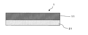
- FIG. 1 The polarizing film with an adhesive layer of the present invention is shown in FIG. 1, for example.
- the polarizing film 1 with an adhesive layer has a polarizing film 11 and an adhesive layer 21.
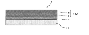
- FIG. 2 shows a case where a single protective polarizing film 11A having a protective film b on only one side of the polarizing element a is used as the polarizing film 11 of FIG. 1, and in the single protective polarizing film 11A, the polarizing element a is used.
- the pressure-sensitive adhesive layer 21 is provided on the other side of the side that does not have the protective film b.
- FIG. 3 shows a case where the one-sided protective polarizing film 11A is used and the transparent layer d is further provided on the other side of the polarizing element a.
- the one-sided protective polarizing film 11A is provided with a transparent layer c and an adhesive layer 21 in this order. It is preferable that the transparent layer c is provided directly on the polarizer a because it is possible to suppress an increase in the water content of the polarizer in a high temperature and high humidity environment.
- the polarizing film with an adhesive layer of the present invention has a deformed portion other than a rectangle.
- FIG. 4 is a top view of an example having a deformed portion other than a rectangle.
- the irregular shape is not particularly limited, and any shape can be taken depending on the application, function, design, etc. of the polarizing film with the adhesive layer.
- the irregular shape other than the rectangle may be, for example, a case where the rectangle has a chipped portion or a through hole.
- the chipped portion is provided on the outer edge of the polarizing film with an adhesive layer.
- a plurality of the chipped portions may have the same shape or different shapes.
- Two or more of the chipped portions may be provided on one side, or one or more may be provided on each of the two sides.
- the chipped portion may be provided at one of the four corners of the outer edge of the rectangle, or may be provided at two or more locations.
- the corners of the outer edge not provided with the chipped portion may be angular or rounded.
- the chipped portion can be formed of a straight line, a curved line, or a combination thereof.
- FIG. 4 is an example of a polarizing film 1 with an adhesive layer having a deformed shape, and chipped portions 2 having different shapes are provided on both short sides of the rectangle.
- the length of the side W1 of the chipped portion is appropriately adjusted according to the use of the polarizing film.
- W1 is preferably adjusted in the range of about 2 to 100 mm.
- the chipped portion 2 is adjusted so that the maximum depth D from the side W1 is about 2 to 100 mm.
- FIG. 4 shows a case where the angle ⁇ 1 formed by the two straight lines forming the shape of the chipped portion 2 is 90 °, but the angle ⁇ 1 is 90 ° or more and less than 180 °, preferably 90 ° or more. It is 135 ° or less.
- the angle ⁇ 1 is out of the above range, the stress based on expansion and contraction is concentrated on the portion 4 where the two straight lines intersect in a harsh environment of thermal impact, and cracks are likely to occur in the portion 4.
- the radius of curvature R1 of the curve is 0.2 mm or more, preferably 1 mm or more, more preferably 2 mm or more, still more preferable. Is 3 mm or more, more preferably 5 mm or more.
- the radius of curvature R1 is less than 0.2 mm, stress based on expansion and contraction is concentrated on the curved portion in a harsh environment of thermal shock, and cracks are likely to occur in the curved portion.
- the through hole is provided inside the plane of the polarizing film with an adhesive layer.
- a plurality of the through holes are provided inside the plane of the polarizing film with the pressure-sensitive adhesive layer, they may have the same shape or different shapes.
- the through hole is composed of a straight line, a curved line, or a combination thereof. Examples of the shape of the through hole include a circle, an ellipse (one axis of symmetry, two axes of symmetry), a rectangle with rounded corners, a quadrangle (square, rectangle), and a polygon having five or more angles. Be done.
- Examples of the method for forming the deformed portion include punching, end milling, and laser processing.
- the deformed portion is usually formed by the processing after laminating each layer.
- each member constituting the polarizing film with an adhesive layer of the present invention will be described.
- the polarizing film a polarizing element and one having a protective film on one side or both sides of the polarizing element is used.
- the polarizer is not particularly limited, and various types of polarizers can be used.
- the polarizer include a hydrophilic polymer film such as a polyvinyl alcohol-based film, a partially formalized polyvinyl alcohol-based film, and an ethylene / vinyl acetate copolymer system partially saponified film, and a bicolor property of iodine or a bicolor dye.
- examples thereof include a uniaxially stretched film by adsorbing a substance, a polyene-based oriented film such as a dehydrated product of polyvinyl alcohol and a dehydrogenated product of polyvinyl chloride.
- a polarizer made of a polyvinyl alcohol-based film and a dichroic substance such as iodine is preferable.
- the thickness of these polarizers is not particularly limited, but is generally about 80 ⁇ m or less.
- a thin polarizer having a thickness of 10 ⁇ m or less can be used as the polarizer. From the viewpoint of thinning, the thickness is preferably 1 to 7 ⁇ m. It is preferable that such a thin polarizing element has less unevenness in thickness, is excellent in visibility, is excellent in durability because there is little dimensional change, and can be made thinner as a polarizing film.
- thermoplastic resin having excellent transparency, mechanical strength, thermal stability, moisture blocking property, isotropic property, etc.
- thermoplastic resins include cellulose resins such as triacetyl cellulose, polyester resins, polyether sulfone resins, polysulfone resins, polycarbonate resins, polyamide resins, polyimide resins, polyolefin resins, (meth) acrylic resins, and cyclic resins.
- examples thereof include polyolefin resins (norbornene-based resins), polyarylate resins, polystyrene resins, polyvinyl alcohol resins, and mixtures thereof.
- a protective film is usually bonded to one side of the polarizer by an adhesive layer, but as a protective film on the other side, (meth) acrylic, urethane, acrylic urethane, epoxy, etc.
- a thermosetting resin such as silicone or an ultraviolet curable resin can be used.
- a cellulose resin and a (meth) acrylic resin are preferable because the fluctuation of the surface resistance value of the pressure-sensitive adhesive layer can be controlled to be small.
- the (meth) acrylic resin it is preferable to use a (meth) acrylic resin having a lactone ring structure.
- the (meth) acrylic resin having a lactone ring structure include JP-A-2000-230016, JP-A-2001-151814, JP-A-2002-120326, JP-A-2002-254544, JP-A-2005 Examples thereof include (meth) acrylic resins having a lactone ring structure described in Japanese Patent Application Laid-Open No. 146084.
- the cellulose resin is preferable to the (meth) acrylic resin in that it is effective in suppressing irregularly shaped cracks and polarizer cracks, which are problems in the single-protective polarizing film.
- a retardation film As the protective film, a retardation film, a brightness improving film, a diffusion film and the like can also be used.
- the retardation film include those having a frontal retardation of 40 nm or more and / or a thickness direction retardation of 80 nm or more.
- the front phase difference is usually controlled in the range of 40 to 200 nm
- the thickness direction phase difference is usually controlled in the range of 80 to 300 nm.
- the retardation film also functions as a polarizer protective film, so that the thickness can be reduced.
- a functional layer such as a hard coat layer, an antireflection layer, a sticking prevention layer, a diffusion layer or an antiglare layer can be provided on the surface of the protective film to which the polarizer is not adhered.
- the protective film and the polarizer are laminated via an intervening layer such as an adhesive layer, an adhesive layer, and an undercoat layer (primer layer). At this time, it is desirable that both are laminated without an air gap by an intervening layer.
- the protective film and the polarizer are preferably laminated via an adhesive layer.
- the adhesive used for bonding the polarizer and the protective film is not particularly limited as long as it is optically transparent, and various forms such as water-based, solvent-based, hot-melt-based, radical-curing type, and cation-curing type are used. However, water-based adhesives or radical curable adhesives are suitable.
- the pressure-sensitive adhesive layer is formed of a pressure-sensitive adhesive composition containing a (meth) acrylic polymer (A) and an ionic compound (B).
- the (meth) acrylic polymer (A) contains an alkyl (meth) acrylate as a main component as a monomer unit.
- (meth) acrylate means acrylate and / or methacrylate, and has the same meaning as (meth) of the present invention.
- alkyl (meth) acrylate constituting the main skeleton of the (meth) acrylic polymer (A) include those having a linear or branched alkyl group having 1 to 18 carbon atoms.
- the alkyl group includes methyl group, ethyl group, propyl group, isopropyl group, butyl group, isobutyl group, amyl group, hexyl group, cyclohexyl group, heptyl group, 2-ethylhexyl group, isooctyl group, nonyl group and decyl.
- Examples thereof include a group, an isodecyl group, a dodecyl group, an isomyristyl group, a lauryl group, a tridecyl group, a pentadecyl group, a hexadecyl group, a heptadecyl group, an octadecyl group and the like. These can be used alone or in combination.
- the average carbon number of these alkyl groups is preferably 3 to 9.
- the weight ratio of the alkyl (meth) acrylate is preferably 70% by weight or more in terms of the weight ratio of all the constituent monomers (100% by weight) constituting the (meth) acrylic polymer (A) as a monomer unit.
- the weight ratio of the alkyl (meth) acrylate can be considered as the balance of the other copolymerized monomers. It is preferable to set the weight ratio of the alkyl (meth) acrylate in the above range in order to ensure adhesiveness.
- (meth) acrylic polymer (A) in addition to the above-mentioned alkyl (meth) acrylate monomer unit, unsaturated (meth) acryloyl group, vinyl group, etc. are used for the purpose of improving adhesiveness and heat resistance.
- One or more types of copolymerizable monomers having a polymerizable functional group having a double bond can be introduced by copolymerization.
- copolymerization monomer examples include functional group-containing monomers such as a carboxyl group-containing monomer, a hydroxyl group-containing monomer, and an amide group-containing monomer.
- the carboxyl group-containing monomer is a compound containing a carboxyl group in its structure and containing a polymerizable unsaturated double bond such as a (meth) acryloyl group and a vinyl group.
- Specific examples of the carboxyl group-containing monomer include (meth) acrylic acid, carboxyethyl (meth) acrylate, carboxypentyl (meth) acrylate, itaconic acid, maleic acid, fumaric acid, crotonic acid and the like.
- acrylic acid is preferable from the viewpoint of copolymerizability, price, and adhesive properties.
- the hydroxyl group-containing monomer is a compound containing a hydroxyl group in its structure and containing a polymerizable unsaturated double bond such as a (meth) acryloyl group or a vinyl group.
- a polymerizable unsaturated double bond such as a (meth) acryloyl group or a vinyl group.
- Specific examples of the hydroxyl group-containing monomer include 2-hydroxyethyl (meth) acrylate, 3-hydroxypropyl (meth) acrylate, 4-hydroxybutyl (meth) acrylate, 6-hydroxyhexyl (meth) acrylate, and 8-hydroxyhexyl (meth) acrylate.
- hydroxyalkyl (meth) acrylates such as hydroxyoctyl (meth) acrylates, 10-hydroxydecyl (meth) acrylates and 12-hydroxylauryl (meth) acrylates, and (4-hydroxymethylcyclohexyl) -methyl acrylates.
- hydroxyl group-containing monomers 2-hydroxyethyl (meth) acrylate and 4-hydroxybutyl (meth) acrylate are preferable, and 4-hydroxybutyl (meth) acrylate is particularly preferable, from the viewpoint of durability.
- the carboxyl group-containing monomer and the hydroxyl group-containing monomer serve as reaction points with the cross-linking agent when the pressure-sensitive adhesive composition contains the cross-linking agent. Since the carboxyl group-containing monomer and the hydroxyl group-containing monomer are highly reactive with the intermolecular cross-linking agent, they are preferably used for improving the cohesiveness and heat resistance of the obtained pressure-sensitive adhesive layer. Further, the carboxyl group-containing monomer is preferable in terms of achieving both durability and reworkability, and the hydroxyl group-containing monomer is preferable in terms of reworkability.
- the weight ratio of the carboxyl group-containing monomer is preferably 10% by weight or less, more preferably 0.01 to 8% by weight, further preferably 0.05 to 6% by weight, and further preferably 0.1 to 0.1% by weight. 5% by weight is preferable. It is preferable that the weight ratio of the carboxyl group-containing monomer is 0.01% by weight or more from the viewpoint of durability. On the other hand, if it exceeds 10% by weight, it is not preferable from the viewpoint of reworkability.
- the weight ratio of the hydroxyl group-containing monomer is preferably 3% by weight or less, more preferably 0.01 to 3% by weight, further preferably 0.1 to 2% by weight, and further 0.2 to 0.2 to 2% by weight. 2% by weight is preferable. It is preferable that the weight ratio of the hydroxyl group-containing monomer is 0.01% by weight or more from the viewpoint of cross-linking the pressure-sensitive adhesive layer, durability and adhesive properties. On the other hand, if it exceeds 3% by weight, it is not preferable from the viewpoint of durability.
- the amide group-containing monomer is a compound containing an amide group in its structure and containing a polymerizable unsaturated double bond such as a (meth) acryloyl group and a vinyl group.
- Specific examples of the amide group-containing monomer include (meth) acrylamide, N, N-dimethyl (meth) acrylamide, N, N-diethyl (meth) acrylamide, N-isopropylacrylamide, N-methyl (meth) acrylamide, and N-.
- the amide group-containing monomer is preferable in suppressing an increase in surface resistance value over time (particularly in a humid environment), satisfying durability, and further suppressing deformed cracks.
- the N-vinyl group-containing lactam-based monomer suppresses an increase in the surface resistance value over time (particularly in a humid environment), and is a transparent conductive layer (touch sensor layer). It is preferable for satisfying the durability against and suppressing irregular cracks.
- the weight ratio of the amide group-containing monomer increases, the anchoring property with respect to the optical film tends to decrease. Therefore, the weight ratio is preferably 10% by weight or less, more preferably 5% by weight or less. Especially preferable.
- the weight ratio of the amide group-containing monomer is preferably 0.1% by weight or more from the viewpoint of suppressing an increase in the surface resistance value over time (particularly in a humid environment).
- the weight ratio is preferably 0.3% by weight or more, more preferably 0.5% by weight or more.
- the amide group-containing monomer is suitable in relation to the ionic compound (B) contained in the pressure-sensitive adhesive layer of the present invention.
- the amide group is present in the pressure-sensitive adhesive composition used for forming the pressure-sensitive adhesive layer. Due to the presence of, the surface resistance value of the pressure-sensitive adhesive layer adjusted by blending the ionic compound (B) is suppressed from fluctuating and increasing even in a humid environment, and is maintained within the desired value range. It is preferable to do so.
- the pressure-sensitive adhesive layer is made of glass or a transparent conductive layer (ITO layer or the like) when an amide group introduced into the side chain of the (meth) acrylic polymer (A) as the base polymer is present.
- ITO layer or the like transparent conductive layer
- the durability is good for all of the above, and it is possible to suppress the occurrence of peeling, floating, etc. in the state of being attached to the liquid crystal panel. Further, the durability can be satisfied even in a humidified environment (after the humidification reliability test).
- an aromatic ring-containing (meth) acrylate As the copolymerization monomer, for example, an aromatic ring-containing (meth) acrylate can be used.
- An aromatic ring-containing (meth) acrylate is a compound having an aromatic ring structure in its structure and containing a (meth) acryloyl group. Examples of the aromatic ring include a benzene ring, a naphthalene ring, and a biphenyl ring.
- aromatic ring-containing (meth) acrylate examples include, for example, benzyl (meth) acrylate, phenyl (meth) acrylate, o-phenylphenol (meth) acrylate phenoxy (meth) acrylate, phenoxyethyl (meth) acrylate, and phenoxypropyl.
- benzene ring such as acrylate, methoxybenzyl (meth) acrylate, chlorobenzyl (meth) acrylate, cresyl (meth) acrylate, polystyryl (meth) acrylate; hydroxyethylated ⁇ -naphthol acrylate, 2-naphthoethyl (meth) acrylate , 2-naphthoxyethyl acrylate, 2- (4-methoxy-1-naphthoxy) ethyl (meth) acrylate or the like having a naphthalene ring; examples thereof include
- aromatic ring-containing (meth) acrylate benzyl (meth) acrylate and phenoxyethyl (meth) acrylate are preferable, and phenoxyethyl (meth) acrylate is particularly preferable, from the viewpoint of adhesive properties and durability.
- the weight ratio of the aromatic ring-containing (meth) acrylate is preferably 25% by weight or less, more preferably 3 to 25% by weight, further preferably 10 to 22% by weight, and further preferably 14 to 20% by weight. Is preferable.
- the weight ratio of the aromatic ring-containing (meth) acrylate is 3% by weight or more, it is preferable in order to suppress display unevenness. On the other hand, if it exceeds 25% by weight, the display unevenness is not sufficiently suppressed, and the durability tends to decrease.
- copolymerization monomers other than the above include; acid anhydride group-containing monomers such as maleic anhydride and itaconic anhydride; caprolactone adducts of acrylic acid; allylsulfonic acid, 2- (meth) acrylamide-2. -Sulfonic acid group-containing monomers such as methylpropanesulfonic acid, (meth) acrylamide propanesulfonic acid, sulfopropyl (meth) acrylate; and phosphoric acid group-containing monomers such as 2-hydroxyethylacryloyl phosphate.
- acid anhydride group-containing monomers such as maleic anhydride and itaconic anhydride
- caprolactone adducts of acrylic acid allylsulfonic acid, 2- (meth) acrylamide-2.
- -Sulfonic acid group-containing monomers such as methylpropanesulfonic acid, (meth) acrylamide propanesulfonic acid, sulfo
- alkylaminoalkyl (meth) acrylates such as aminoethyl (meth) acrylate, N, N-dimethylaminoethyl (meth) acrylate, and t-butylaminoethyl (meth) acrylate; methoxyethyl (meth) acrylate, ethoxyethyl ( Alkoxyalkyl (meth) acrylates such as meta) acrylates; N- (meth) acryloyloxymethylene succinimide, N- (meth) acryloyl-6-oxyhexamethylene succinimide, N- (meth) acryloyl-8-oxyoctamethylene succinimide, etc.
- Succinimide-based monomers such as N-cyclohexyl maleimide, N-isopropyl maleimide, N-lauryl maleimide and N-phenylmaleimide; N-methylitaconimide, N-ethylitaconimide, N-butylitaconimide, N- Itaconimide-based monomers such as octylitaconimide, N-2-ethylhexylitaconimide, N-cyclohexylitaconimide, and N-laurylitaconimide are also mentioned as examples of monomers for modification purposes.
- a vinyl-based monomer such as vinyl acetate and vinyl propionate; a cyanoacrylate-based monomer such as acrylonitrile and methacrylonitrile; an epoxy group-containing (meth) acrylate such as glycidyl (meth) acrylate; and polyethylene glycol (meth).
- Glycol-based (meth) acrylates such as acrylates, polypropylene glycol (meth) acrylates, methoxyethylene glycol (meth) acrylates, and methoxypolypropylene glycol (meth) acrylates; tetrahydrofurfuryl (meth) acrylates, fluorine (meth) acrylates, silicones (meth).
- (Meta) acrylate monomers such as acrylate and 2-methoxyethyl acrylate can also be used. Further, isoprene, butadiene, isobutylene, vinyl ether and the like can be mentioned.
- examples of copolymerizable monomers other than the above include silane-based monomers containing a silicon atom.
- examples of the silane-based monomer include 3-acryloxypropyltriethoxysilane, vinyltrimethoxysilane, vinyltriethoxysilane, 4-vinylbutyltrimethoxysilane, 4-vinylbutyltriethoxysilane, and 8-vinyloctyltrimethoxysilane.
- 8-Vinyloctyloxydecyltriethoxysilane 10-methacryloyloxydecyltrimethoxysilane, 10-acryloyloxydecyltrimethoxysilane, 10-methacryloyloxydecyltriethoxysilane, 10-acryloyloxydecyltriethoxysilane and the like.
- copolymerization monomer examples include tripropylene glycol di (meth) acrylate, tetraethylene glycol di (meth) acrylate, 1,6-hexanediol di (meth) acrylate, bisphenol A diglycidyl ether di (meth) acrylate, and neo.
- the proportion of the other copolymerized monomer in the (meth) acrylic polymer (A) is about 0 to 10% by weight based on the weight ratio of all the constituent monomers (100% by weight) of the (meth) acrylic polymer (A). Further, it is preferably about 0 to 7% by weight, more preferably about 0 to 5% by weight.
- the (meth) acrylic polymer (A) of the present invention usually preferably has a weight average molecular weight of 1 million to 2.5 million. Considering durability, particularly heat resistance, the weight average molecular weight is preferably 1.2 million to 2 million. When the weight average molecular weight is 1 million or more, it is preferable from the viewpoint of heat resistance. Further, when the weight average molecular weight is larger than 2.5 million, the adhesive tends to be hard and peeling is likely to occur.
- the weight average molecular weight (Mw) / number average molecular weight (Mn) which indicates the molecular weight distribution, is preferably 1.8 or more and 10 or less, more preferably 1.8 to 7, and further 1.8 to. It is preferably 5.
- the weight average molecular weight and the molecular weight distribution (Mw / Mn) are measured by GPC (gel permeation chromatography) and obtained from the values calculated by polystyrene conversion.
- the obtained (meth) acrylic polymer (A) may be any of a random copolymer, a block copolymer, a graft copolymer and the like.
- solution polymerization for example, ethyl acetate, toluene and the like are used as the polymerization solvent.
- the reaction is carried out under an inert gas stream such as nitrogen, a polymerization initiator is added, and usually at about 50 to 70 ° C. under reaction conditions of about 5 to 30 hours.
- the polymerization initiator, chain transfer agent, emulsifier, etc. used for radical polymerization are not particularly limited and can be appropriately selected and used.
- the weight average molecular weight of the (meth) acrylic polymer (A) can be controlled by the amount of the polymerization initiator and the chain transfer agent used, and the reaction conditions, and the amount used is appropriately adjusted according to these types. To.
- ionic compound (B) contained in the pressure-sensitive adhesive composition forming the pressure-sensitive adhesive layer of the present invention a compound having a cation component with a molecular weight of 210 or less is used.
- the molecular weight of the cation component is preferably 150 or less, more preferably 110 or less, further preferably 50 or less, and further 10 It is preferably as follows. The larger the molecular weight of the cation component, the more the (meth) acrylic polymers in the pressure-sensitive adhesive layer are prevented from being entangled with each other, and the physical properties of the pressure-sensitive adhesive layer tend to be softened.
- an alkali metal salt and / or an organic cation-anionic salt can be preferably used.
- the alkali metal salt organic salts and inorganic salts of alkali metals can be used.
- the term "organic cation-anionic salt” as used in the present invention refers to an organic salt whose cation component is composed of an organic substance, and the anion component may be an organic substance or an inorganic substance. There may be.
- the "organic cation-anionic salt” is also referred to as an ionic liquid or an ionic solid.
- the surface resistance value of the pressure-sensitive adhesive layer can be lowered to suppress the generation of static electricity, and the orientation of the liquid crystal layer due to electrification is disturbed and light leakage (light leakage). It is possible to suppress the occurrence of uneven charging).
- alkali metal ions constituting the cationic component of the alkali metal salt include lithium, sodium, and potassium ions. Among these alkali metal ions, lithium ions are preferable.
- the anionic component of the alkali metal salt may be composed of an organic substance or an inorganic substance.
- the anion components constituting the organic salt include CH 3 COO ⁇ , CF 3 COO ⁇ , CH 3 SO 3 ⁇ , CF 3 SO 3 ⁇ , (CF 3 SO 2 ) 3 C ⁇ , C 4 F 9 SO 3 -, C 3 F 7 COO - , (CF 3 SO 2) (CF 3 CO) N -, - O 3 S (CF 2) 3 SO 3 -, PF 6 -, CO 3 2-, or the following general formula ( 1) to (4), (1) :( C n F 2n + 1 SO 2) 2 N - ( where, n is an integer of 0 to 10), (2): CF 2 (C m F 2m SO 2) 2 N - ( where, m is an integer of from 1 to 10), (3): - O 3 S (CF 2) l SO 3 - ( where, l is an integer of from 1 to 10), (4): (C p F
- an anionic component containing a fluorine atom is preferably used because an ionic compound having good ionic dissociation property can be obtained.
- the anionic component constituting the inorganic salts, Cl -, Br -, I -, AlCl 4 -, Al 2 Cl 7 -, BF 4 -, PF 6 -, ClO 4 -, NO 3 -, AsF 6 -, SbF 6 -, NbF 6 -, TaF 6 -, (CN) 2 N -, and the like can be used.
- anionic component (CF 3 SO 2) 2 N -, (C 2 F 5 SO 2) 2 N -, wherein represented by formula (1) etc., (perfluoroalkyl sulfonyl) imide are preferable, especially ( A (trifluoromethanesulfonyl) imide represented by CF 3 SO 2 ) 2 N ⁇ is preferred.
- organic salt of the alkali metal examples include sodium acetate, sodium alginate, sodium lignin sulfonate, sodium toluene sulfonate, LiCF 3 SO 3 , Li (CF 3 SO 2 ) 2 N, and Li (CF 3 SO 2).
- Inorganic salts of alkali metals include lithium perchlorate and lithium iodide.
- the organic cation-anion salt used in the present invention is composed of a cation component and an anion component, and the cation component is composed of an organic substance.
- the cation component include pyridinium cation, piperidinium cation, pyrrolidinium cation, cation having a pyrroline skeleton, cation having a pyrrole skeleton, imidazolium cation, tetrahydropyrimidinium cation, and dihydropyrimidinium cation.
- Examples thereof include pyrazolium cation, pyrazolinium cation, tetraalkylammonium cation, trialkylsulfonium cation, tetraalkylphosphonium cation and the like.
- the anionic component e.g., Cl -, Br -, I -, AlCl 4 -, Al 2 Cl 7 -, BF 4 -, PF 6 -, ClO 4 -, NO 3 -, CH 3 COO -, CF 3 COO -, CH 3 SO 3 -, CF 3 SO 3 -, (CF 3 SO 2) 3 C -, AsF 6 -, SbF 6 -, NbF 6 -, TaF 6 -, (CN) 2 N -, C 4 F 9 SO 3 ⁇ , C 3 F 7 COO ⁇ , ((CF 3 SO 2 ) (CF 3 CO) N ⁇ , ⁇ O 3 S (CF 2 ) 3 SO 3 ⁇ , and the following general formulas (1) to (4) ), (1) :( C n F 2n + 1 SO 2) 2 N - ( where, n is an integer of 0 to 10), (2): CF 2 (C m F 2m SO 2) 2 N - ( where,
- organic cation-anion salt a compound composed of a combination of the above cation component and an anion component is appropriately selected and used.
- Preferred specific examples of the organic cation-anionic salt include, for example, methyltrioctylammonium bis (trifluoromethanesulfonyl) imide, 1-methyl-1-propylpyrrolidinium bis (trifluoromethanesulfonyl) imide, and ethylmethylimidazolium bis (trifluoromethanesulfonyl) imide. Fluorosulfonylimide). Of these, 1-methyl-1-propylpyrrolidinium bis (trifluoromethanesulfonyl) imide and ethyl methylimidazolium bis (fluorosulfonylimide) are more preferable.
- inorganic salts such as ammonium chloride, aluminum chloride, copper chloride, ferric chloride, ferric chloride and ammonium sulfate Can be mentioned.
- alkali metal ions such as lithium, sodium, and potassium are cationic components having a molecular weight of 210 or less. Therefore, alkali metals containing these alkali metal ions as cationic components. Salt can be preferably used.
- an organic salt of an alkali metal in which the anionic component of the alkali metal salt is composed of an organic substance is preferable.
- the alkali metal ion lithium ion having the smallest molecular weight is preferable.
- a lithium salt is preferable, and an organic salt of lithium is particularly preferable.
- the ionic compound (B) is an organic cation-anion salt
- a molecular weight of 210 or less can be selected and used from the above-exemplified cation components.
- an organic cation-anion salt in which the anionic component is composed of an organic substance is preferable.
- the proportion of the ionic compound (B) in the pressure-sensitive adhesive composition of the present invention can be appropriately adjusted so as to satisfy the antistatic properties of the pressure-sensitive adhesive layer and the sensitivity of the touch panel.
- a touch sensing function is built in while considering the type of protective film of the polarizing film so that the surface resistance value of the adhesive layer is in the range of 1.0 ⁇ 10 8 to 1.0 ⁇ 10 12 ⁇ / ⁇ .
- the initial surface resistance value of the adhesive layer is 1 ⁇ 10 10 to 1 ⁇ 10 12 ⁇ /. It is preferable to control within the range of ⁇ .
- the ratio of the ionic compound (B) is, for example, preferably 40 parts by weight or less, more preferably 20 parts by weight or less, based on 100 parts by weight of the (meth) acrylic polymer (A). Is preferable, and more preferably 13 parts by weight or less.
- the ionic compound (B) is preferably 1 part by weight or more, more preferably 5 parts by weight or more.
- the pressure-sensitive adhesive composition of the present invention can contain a cross-linking agent (C).
- a cross-linking agent C
- an organic cross-linking agent or a polyfunctional metal chelate can be used.
- the organic cross-linking agent include isocyanate-based cross-linking agents, peroxide-based cross-linking agents, epoxy-based cross-linking agents, and imine-based cross-linking agents.
- a polyfunctional metal chelate is one in which a polyvalent metal is covalently or coordinated to an organic compound.
- Examples of the polyvalent metal atom include Al, Cr, Zr, Co, Cu, Fe, Ni, V, Zn, In, Ca, Mg, Mn, Y, Ce, Sr, Ba, Mo, La, Sn, Ti and the like. Can be mentioned.
- Examples of the atom in the organic compound having a covalent bond or a coordination bond include an oxygen atom and the like, and examples of the organic compound include an alkyl ester, an alcohol compound, a carboxylic acid compound, an ether compound and a ketone compound.
- cross-linking agent (C) an isocyanate-based cross-linking agent and / or a peroxide-based cross-linking agent is preferable.
- isocyanate-based cross-linking agent (C) a compound having at least two isocyanate groups can be used.
- known aliphatic polyisocyanates, alicyclic polyisocyanates, aromatic polyisocyanates, etc., which are generally used for urethanization reactions, are used.
- any peroxide that generates radically active species by heating or light irradiation to promote cross-linking of the base polymer of the pressure-sensitive adhesive composition can be appropriately used, but in consideration of workability and stability. It is preferable to use a peroxide having a half-life temperature of 80 ° C. to 160 ° C. for 1 minute, and more preferably to use a peroxide having a half-life temperature of 90 ° C. to 140 ° C.
- peroxide examples include di (2-ethylhexyl) peroxydicarbonate (1 minute half-life temperature: 90.6 ° C.) and di (4-t-butylcyclohexyl) peroxydicarbonate (1).
- the amount of the cross-linking agent (C) used is preferably 3 parts by weight or less, more preferably 0.01 to 3 parts by weight, and further 0.02 with respect to 100 parts by weight of the (meth) acrylic polymer (A). It is preferably from 2 parts by weight, more preferably 0.03 to 1 part by weight. If the amount of the cross-linking agent (C) is less than 0.01 parts by weight, the pressure-sensitive adhesive layer may be insufficiently cross-linked and the durability and adhesive properties may not be satisfied. There is a tendency for it to become too hard and its durability to decrease.
- the pressure-sensitive adhesive composition of the present invention can contain a silane coupling agent (D).
- Durability can be improved by using the silane coupling agent (D).
- Specific examples of the silane coupling agent include 3-glycidoxypropyltrimethoxysilane, 3-glycidoxypropyltriethoxysilane, 3-glycidoxypropylmethyldiethoxysilane, and 2- (3, 4-Epylcyclohexyl) Epyl group-containing silane coupling agent such as ethyltrimethoxysilane, 3-aminopropyltrimethoxysilane, N-2- (aminoethyl) -3-aminopropylmethyldimethoxysilane, 3-triethoxysilyl- Amino group-containing silane coupling agents such as N- (1,3-dimethylbutylidene) propylamine and N-phenyl- ⁇ -aminopropyltrimethoxysilane, 3-acryloxy
- Examples thereof include (meth) acrylic group-containing silane coupling agents such as ethoxysilane, and isocyanate group-containing silane coupling agents such as 3-isocyanuppropyltriethoxysilane.
- an epoxy group-containing silane coupling agent is preferable.
- silane coupling agent (D) one having a plurality of alkoxysilyl groups in the molecule can also be used.
- a silane coupling agent having a plurality of alkoxysilyl groups in these molecules is preferable because it is difficult to volatilize and has a plurality of alkoxysilyl groups, which is effective in improving durability.
- the adherend of the optical film with the pressure-sensitive adhesive layer is a transparent conductive layer (for example, ITO or the like) in which the alkoxysilyl group is less likely to react than glass.
- the silane coupling agent having a plurality of alkoxysilyl groups in the molecule preferably has an epoxy group in the molecule, and more preferably has a plurality of epoxy groups in the molecule.
- a silane coupling agent having a plurality of alkoxysilyl groups in the molecule and having an epoxy group tends to have good durability even when the adherend is a transparent conductive layer (for example, ITO).
- silane coupling agent having a plurality of alkoxysilyl groups in the molecule and having an epoxy group examples include X-41-1053, X-41-1059A, and X-41-1056 manufactured by Shin-Etsu Chemical Co., Ltd.
- X-41-1056 manufactured by Shin-Etsu Chemical Co., Ltd. which has a high epoxy group content, is preferable.
- the silane coupling agent (D) may be used alone or in combination of two or more, but the content as a whole is the (meth) acrylic polymer (A) 100. It is preferably 5 parts by weight or less, more preferably 0.001 to 5 parts by weight, further preferably 0.01 to 1 part by weight, still more preferably 0.02 to 1 part by weight, and further. Is preferably 0.05 to 0.6 parts by weight. It is an amount that improves durability.
- the pressure-sensitive adhesive composition of the present invention may contain other known additives, for example, a polyether compound having a reactive silyl group, a polyether compound of polyalkylene glycol such as polypropylene glycol, and coloring. Powders of agents, pigments, dyes, surfactants, plasticizers, tackifiers, surface lubricants, leveling agents, softeners, antioxidants, antioxidants, light stabilizers, UV absorbers, polymerization prohibited Agents, inorganic or organic fillers, metal powders, particles, foils and the like can be appropriately added depending on the intended use. Further, a redox system to which a reducing agent is added may be adopted within a controllable range. These additives are preferably used in a range of 5 parts by weight or less, further 3 parts by weight or less, and further 1 part by weight or less with respect to 100 parts by weight of the (meth) acrylic polymer (A).
- a polyether compound having a reactive silyl group such as polypropylene glycol
- the pressure-sensitive adhesive composition is applied to a peeled separator or the like, and a polymerization solvent or the like is dried and removed to form a pressure-sensitive adhesive layer, which is then transferred to an optical film (polarizing film).
- a polymerization solvent or the like is dried and removed to form a pressure-sensitive adhesive layer, which is then transferred to an optical film (polarizing film).
- This is produced by a method of applying the pressure-sensitive adhesive composition to an optical film (polarizing film) and drying and removing a polymerization solvent or the like to form a pressure-sensitive adhesive layer on the optical film.
- one or more solvents other than the polymerization solvent may be newly added as appropriate.
- the thickness of the pressure-sensitive adhesive layer is not particularly limited, and is, for example, about 1 to 100 ⁇ m. It is preferably 2 to 50 ⁇ m, more preferably 2 to 40 ⁇ m, and even more preferably 5 to 35 ⁇ m.
- the pressure-sensitive adhesive layer applied to the polarizing film with a pressure-sensitive adhesive layer of the present invention preferably has a creep value of 120 ⁇ m or less, more preferably 100 ⁇ m or less, at 85 ° C. from the viewpoint of being applied to a deformed polarizing film. It is more preferably 85 ⁇ m or less, and particularly preferably 60 ⁇ m or less.
- the lower limit of the creep value is preferably 15 ⁇ m or more, more preferably 30 ⁇ m or more. If the creep value exceeds 120 ⁇ m, cracks that occur in the deformed polarizing film may be exacerbated as described in Examples. If the creep value is less than 15 ⁇ m, the stress relaxation property of the pressure-sensitive adhesive layer is lowered, so that the pressure-sensitive adhesive layer may be easily peeled off in the durability test.
- the thickness of the transparent layer is preferably 10 ⁇ m or less, more preferably 5 ⁇ m or less, further preferably 3 ⁇ m or less, and further 1. It is preferably 5 ⁇ m or less, and more preferably 1 ⁇ m or less. If the transparent layer is too thick, the thickness of the polarizing film may increase, and the optical reliability of the polarizer may be reduced. On the other hand, the thickness of the transparent layer is preferably 0.1 ⁇ m or more, more preferably 0.2 ⁇ m or more, still more preferably 0.3 ⁇ m or more, from the viewpoint of suppressing the fluctuation ratio of the surface resistance value of the pressure-sensitive adhesive layer to be small. Is preferable.
- a material having transparency and capable of suppressing the influence of the pressure-sensitive adhesive layer on the polarizer can be used.
- examples of such a material include a forming material containing a urethane prepolymer (a) which is a reaction product of an isocyanate compound and a polyhydric alcohol.
- a polyfunctional isocyanate compound for example, a polyfunctional isocyanate compound is preferable, and specific examples thereof include a polyfunctional aromatic isocyanate compound, an alicyclic isocyanate, an aliphatic isocyanate compound, or a dimer thereof.
- polyfunctional aromatic isocyanate compound examples include phenylenediocyanate, 2,4-tolylene diisocyanate, 2,6-tolylene diisocyanate, 2,2'-diphenylmethane diisocyanate, and 4,4'-diphenylmethane diisocyanate, 4 , 4'-toluidine diisocyanate, 4,4'-diphenyl ether diisocyanate, 4,4'-diphenyl diisocyanate, 1,5-naphthalenediocyanate, xylylene diisocyanate, methylenebis 4-phenylisocyanate, p-phenylenediisocyanate, and the like.
- polyfunctional alicyclic isocyanate compound examples include 1,3-cyclopentene diisocyanate, 1,3-cyclohexanediisocyanate, 1,4-cyclohexanediisocyanate, 1,3-bisisocyanatomethylcyclohexane, isophorone diisocyanate, and hydrogen.
- examples thereof include added diphenylmethane diisocyanate, hydrogenated xylylene diisocyanate, hydrogenated tolylene diisocyanate, and hydrogenated tetramethylxylylene diisocyanate.
- polyfunctional aliphatic isocyanate compound examples include trimethylene diisocyanate, tetramethylene diisocyanate, hexamethylene diisocyanate, pentamethylene diisocyanate, 1,2-propylene diisocyanate, 1,3-butylene diisocyanate, dodecamethylene diisocyanate, 2,4.
- polyfunctional aliphatic isocyanate compound examples include trimethylene diisocyanate, tetramethylene diisocyanate, hexamethylene diisocyanate, pentamethylene diisocyanate, 1,2-propylene diisocyanate, 1,3-butylene diisocyanate, dodecamethylene diisocyanate, 2,4.
- Examples thereof include 4-trimethylhexamethylene diisocyanate.
- polyfunctional isocyanate compound examples include those having three or more isocyanate groups such as trisisocyanurate (6-incyanate hexyl).
- polyhydric alcohol examples include ethylene glycol, diethylene glycol, 1,3-butanediol, 1,4-butanediol, neopentyl glycol, 3-methyl-1,5-pentanediol, and 2-butyl-2-ethyl-.
- the urethane prepolymer (a) in the present invention, it is possible to use a urethane prepolymer having a rigid structure in which a cyclic structure (benzene ring, cyanurate ring, isocyanurate ring, etc.) occupies a large proportion in the structure.
- the polyfunctional isocyanate compound may be used alone or in combination of two or more, but an aromatic isocyanate compound is preferable from the viewpoint of suppressing water mixing into the polarizer.
- Other polyfunctional isocyanate compounds can be used in combination with aromatic isocyanate compounds.
- the aromatic isocyanate compounds it is preferable to use at least one selected from tolylene diisocyanate and diphenylmethane diisocyanate as the isocyanate compound.
- the urethane prepolymer (a) trimethylolpropane-tri-tolylenisocyanate and trimethylolpropane-tri-diphenylmethane diisocyanate are preferably used.
- the urethane prepolymer (a) is a compound having a terminal isocyanate group, and is obtained, for example, by mixing an isocyanate compound and a polyhydric alcohol, stirring and reacting them. Usually, it is preferable to mix the isocyanate compound and the polyhydric alcohol so that the isocyanate group is excessive with respect to the hydroxyl group of the polyhydric alcohol.
- urethane prepolymer (a) one having a protective group added to a terminal isocyanate group can also be used.
- Protecting groups include oxime and lactam. When the isocyanate group is protected, the protecting group is dissociated from the isocyanate group by heating, and the isocyanate group reacts.
- the forming material for forming the transparent layer can contain, in addition to the urethane prepolymer (a), a compound (b) having at least two functional groups having active hydrogen reactive with an isocyanate group.
- the functional group having an active hydrogen reactive with the isocyanate group include a hydroxyl group and an amino group.
- the number of active hydrogen-containing functional groups of the compound (b) increases, the number of reaction points of the urethane prepolymer (a) with the isocyanate groups increases and a cured product is easily formed. Therefore, the number of the functional groups is 3. The above is preferable.
- the value of the compound (b) obtained by dividing its molecular weight by the number of the functional groups is preferably 350 or less.
- the molecular weight of the compound (b) is preferably 1000 or less.
- a compound (b) having a molecular weight in the range of 1000 or less is preferable in terms of compatibility when preparing a forming material as a solution together with the urethane prepolymer (a).
- Examples of the compound (b) include polyhydric alcohols, polyvalent amines, compounds having a hydroxyl group and an amino group in the molecule, and the like.
- polyhydric alcohol examples include ethylene glycol, diethylene glycol, 1,3-butanediol, 1,4-butanediol, neopentyl glycol, 3-methyl-1,5-pentanediol, and 2-butyl-2-ethyl-.
- alkylene oxide for example, propylene oxide
- polyvalent amine examples include ethylenediamine, propylenediamine, hexamethylenediamine, diethylenetriamine, triethylenetetramine, isophoronediamine, dicyclohexylmethane-4,4'-diamine, dimerdiamine and the like.
- Examples of the compound having a hydroxyl group and an amino group in the molecule include 2-hydroxyethylethylenediamine, 2-hydroxyethylpropylenediamine, di-2-hydroxyethylethylenediamine, di-2-hydroxyethylpropylenediamine, and 2-hydroxy.
- Diamines having a hydroxyl group in the molecule such as propylethylenediamine and di-2-hydroxypropylethylenediamine; Examples thereof include alkanolamines such as ethanolamine, diethanolamine and triethanolamine.
- a polyhydric alcohol as the compound (b) from the viewpoint of preventing deterioration of the optical reliability of the polarizer, and in particular, trimethylolpropane is preferable from the viewpoint of reactivity with the urethane prepolymer (a). preferable.
- the forming material contains the urethane prepolymer (a) as a main component.
- the urethane prepolymer (a) preferably contains 50% by weight or more of the solid content of the forming material.
- the compounding ratio of the compound (b) to the urethane prepolymer (a) is 5% by weight or more with respect to the total 100% by weight (solid content ratio) of the urethane prepolymer (a) and the compound (b). It is preferable to have it.
- the blending ratio of the compound (b) is preferably 10% by weight or more from the viewpoint of improving the film strength.
- the compounding ratio of the compound (b) is 80% by weight or less, further 50% by weight or less. Is preferable.
- the forming material can use a reaction catalyst in order to further increase the reactivity of the isocyanate group.
- the reaction catalyst is not particularly limited, but a tin catalyst or an amine catalyst is preferable.
- One kind or two or more kinds of reaction catalysts can be used.
- the amount of the reaction catalyst used is usually 5 parts by weight or less with respect to 100 parts by weight of the urethane prepolymer (a). When the amount of the reaction catalyst is large, the crosslinking reaction rate becomes high and the forming material foams. Sufficient adhesiveness cannot be obtained even if the foamed forming material is used.
- 0.01 to 5 parts by weight, more preferably 0.05 to 4 parts by weight 0.01 to 5 parts by weight, more preferably 0.05 to 4 parts by weight.
- a reaction catalyst can be used to further increase the reactivity of the isocyanate group.
- the reaction catalyst is not particularly limited, but a tin catalyst or an amine catalyst is preferable.
- One kind or two or more kinds of reaction catalysts can be used.
- the amount of the reaction catalyst used is usually 5 parts by weight or less with respect to 100 parts by weight of the urethane prepolymer. When the amount of the reaction catalyst is large, the crosslinking reaction rate becomes high and the forming material foams. Sufficient adhesiveness cannot be obtained even if the foamed forming material is used.
- 0.01 to 5 parts by weight, more preferably 0.05 to 4 parts by weight 0.01 to 5 parts by weight, more preferably 0.05 to 4 parts by weight.
- the tin catalyst either an inorganic catalyst or an organic catalyst can be used, but an organic catalyst is preferable.
- the inorganic tin-based catalyst include stannous chloride and stannic chloride.
- the organic tin catalyst preferably has at least one organic group such as an aliphatic group having a skeleton such as a methyl group, an ethyl group, an ether group or an ester group, and an alicyclic group.
- tetra-n-butyltin tri-n-butyltin acetate, n-butyltin trichloride, trimethyltin hydroxide, dimethyltin dichloride, dibutyltin dilaurate and the like can be mentioned.
- the amine-based catalyst is not particularly limited. For example, those having at least one organic group such as an alicyclic group such as quinoclydin, amidine, and diazabicycloundecene are preferable. Other examples of the amine-based catalyst include triethylamine and the like. Examples of reaction catalysts other than the above include cobalt naphthenate, benzyltrimethylammonium hydroxide and the like.
- the forming material is usually used as a solution containing the urethane prepolymer (a) and the compound (b).
- the solution may be solvent-based or aqueous-based such as an emulsion, colloidal dispersion, or aqueous solution.
- the organic solvent is not particularly limited as long as it does not have a functional group having active hydrogen reactive with an isocyanate group and uniformly dissolves the urethane prepolymer (a) and the compound (b) constituting the forming material. Absent.
- the organic solvent may be used alone or in combination of two or more. Further, as the organic solvent, different solvents can be used for the urethane prepolymer (a) and the compound (b).
- the forming material can be prepared by mixing each solution after preparing each solution. Further, the viscosity of the forming material can be adjusted by further adding an organic solvent to the prepared forming material. Further, in the case of a solvent-based solution dissolved in an organic solvent, alcohols, water and the like illustrated below can be contained as a solvent.
- Organic solvents include aromatic hydrocarbons such as toluene and xylene); esters such as ethyl acetate and butyl acetate; aliphatic or alicyclic hydrocarbons such as hexane, cyclohexane and methylcyclohexane; 1,2-dichloroethane.
- Alkanes such as halogenated alkanes; ethers such as tert-butyl methyl ether; ketones such as methyl ethyl ketone, methyl isobutyl ketone, cyclohexanone, cyclopentanone, acetylacetone; and the like.
- aqueous system for example, alcohols such as n-butyl alcohol and isopropyl alcohol, and ketones such as acetone can be blended.
- a dispersant is used, or a functional group that is less reactive with isocyanate groups such as carboxylates, sulfonates, and quaternary ammonium salts, and water dispersibility such as polyethylene glycol are used in urethane prepolymers. This can be done by introducing the ingredients.
- Examples of the material for forming the transparent layer other than the urethane prepolymer include a cyanoacrylate-based forming material, an epoxy-based forming material, and a urethane acrylate-based forming material.
- the formation of the transparent layer can be appropriately selected according to the type of the forming material.
- the transparent layer can be formed by applying the forming material to a polarizer or the like and then curing the transparent layer. Can be obtained as a layer. Usually, after the coating, it is dried at about 30 to 100 ° C., preferably 50 to 80 ° C. for about 0.5 to 15 minutes to form a cured layer. Furthermore, when the forming material contains an isocyanate component, annealing treatment is performed at about 30 to 100 ° C., preferably 50 to 80 ° C. for about 0.5 to 24 hours in order to promote the reaction. Can be done.
- the polarizing film with an adhesive layer of the present invention can be applied to various image display panels, and the image display panel can be applied to a conventional image display device.
- Other configurations of the image display device are the same as those of the conventional image display device.
- Specific examples of the image display device to which the image display panel can be applied include a liquid crystal display device, an electroluminescence (EL) display, a plasma display (PD), a field emission display (FED), and the like. ..
- the polarizing film with an adhesive layer of the present invention has a small fluctuation ratio of the surface resistance value, and is suitable for application to a liquid crystal panel with a built-in touch sensing function.
- an optical film such as a retardation film, a viewing angle compensation film, and a brightness improving film can be appropriately provided on the liquid crystal panel.
- the liquid crystal layer is not particularly limited, and for example, any type such as TN type, STN type, ⁇ type, VA type, IPS type and the like can be used.
- the transparent substrate 9 (light source side) may be a transparent substrate, and the material thereof is not particularly limited, and examples thereof include glass and a transparent resin film substrate. Examples of the transparent resin film base material include those described above.
- a polarizing film with an adhesive layer conventionally used in this field can be used on the light source side of the liquid crystal layer, and the one described in the present specification can also be preferably used.
- FIGS. 6 to 8 Specific examples of the liquid crystal panel with a built-in touch sensing function are shown in FIGS. 6 to 8, for example.
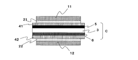
- 6 to 8 illustrate a case where the polarizing film with an adhesive layer shown in FIG. 1 is used on the visual side of the liquid crystal cell as the polarizing film with an adhesive layer of the present invention. That is, the one-sided protective polarizing film 11 and the pressure-sensitive adhesive layer 21 of FIG. 1 are shown as the first polarizing film 11 and the first pressure-sensitive adhesive layer 21 in FIGS. 6 to 8.
- FIG. 6 a so-called in-cell type liquid crystal panel with a built-in touch sensing function.
- the liquid crystal cell C has a touch sensor unit 5 and a drive electrode / sensor in the first and second glass substrates 41 and 42 (inside the liquid crystal cell) sandwiching the liquid crystal layer 3. It has a part 6.
- FIG. 7 is a modified example of a so-called in-cell type (semi-in-cell type) liquid crystal panel having a built-in touch sensing function.
- the first polarizing film 11 / first adhesive layer 21 / touch sensor unit 5 / first has a configuration of 1 transparent substrate 41 / liquid crystal layer 3 / drive electrode / sensor unit 6 / second transparent substrate 42 / second adhesive layer 22 / second polarizing film 12.
- the liquid crystal cell C is outside the first transparent substrate 41 and the touch sensor unit 5 is in direct contact with the first adhesive layer 21 and sandwiches the liquid crystal layer 3.
- a drive electrode / sensor unit 6 is provided on the side of the second transparent substrate 42 in the first and second glass substrates 41 and 42 (inside the liquid crystal cell).
- FIG. 8 is a so-called on-cell type liquid crystal panel with a built-in touch sensing function, and from the visual side, the first polarizing film 11 / first adhesive layer 21 / touch sensor unit 5 / drive electrode / sensor unit 6 / third. It has a configuration of 1 transparent substrate 41 / liquid crystal layer 3 / drive electrode 7 / second transparent substrate 42 / second adhesive layer 22 / second polarizing film 12.
- the liquid crystal cell C has a touch sensor unit 5 and a drive electrode / sensor unit 6 outside the first transparent substrate 41, and the touch sensor unit 5 is the first.
- a drive electrode 7 is provided on the side of the second transparent substrate 42 in the first and second glass substrates 41 and 42 (inside the liquid crystal cell) that are in direct contact with the pressure-sensitive adhesive layer 21 and sandwich the liquid crystal layer 3.
- the liquid crystal panel with a built-in touch sensing function of the present invention is suitably applied to the in-cell type (modified example) shown in FIG. 7 or the on-cell type liquid crystal panel with a built-in touch sensing function shown in FIG. 8 among the above examples.
- the first polarizing film 11 arranged on the viewing side of the liquid crystal cell C and the second polarizing film 12 arranged on the opposite side of the viewing side may be different optical films depending on the suitability of the respective arrangement locations. It can be used in layers. Examples of the other optical film include forming a liquid crystal display device such as a reflecting plate, an antitransmissive plate, a retardation film (including a wave plate such as 1/2 or 1/4), a visual compensation film, and a brightness improving film. An optical layer that may be used in the above. These can be used in one layer or two or more layers. Even when these other optical films are used, it is preferable that the pressure-sensitive adhesive layer on the liquid crystal layer 3 side is the first pressure-sensitive adhesive layer 21.
- liquid crystal layer 3 included in the liquid crystal cell C a liquid crystal layer containing liquid crystal molecules homogenically oriented in the absence of an electric field, which is applied to a liquid crystal panel with a built-in touch sensing function, is used.
- liquid crystal layer 3 for example, an IPS type liquid crystal layer is preferably used.
- any type of liquid crystal layer such as TN type, STN type, ⁇ type, and VA type can be used.
- the thickness of the liquid crystal layer is, for example, about 1.5 ⁇ m to 4 ⁇ m.
- the first transparent substrate 41 and the second transparent substrate 42 can form a liquid crystal cell with the liquid crystal layer 3 interposed therebetween.
- a touch sensor unit 5, a drive electrode / sensor unit 6, a drive electrode 7, and the like are formed inside or outside the liquid crystal cell, depending on the form of the liquid crystal panel with a built-in touch sensing function. Further, a color filter substrate can be provided on the liquid crystal cell (first transparent substrate 41).
- Examples of the material for forming the transparent substrate include glass or a polymer film.
- Examples of the polymer film include polyethylene terephthalate, polycycloolefin, polycarbonate and the like.
- When the transparent substrate is made of glass its thickness is, for example, about 0.3 mm to 1 mm.
- the transparent substrate may have an easy-adhesion layer or a hard coat layer on its surface.
- the touch sensor unit 5 (capacitance sensor), the drive electrode / sensor unit 6, and the drive electrode 7 are formed as a transparent conductive layer.
- the constituent material of the transparent conductive layer is not particularly limited, and for example, metals such as gold, silver, copper, platinum, palladium, aluminum, nickel, chromium, titanium, iron, cobalt, tin, magnesium, and tungsten, and metals such as these metals. Examples include alloys.
- Examples of the constituent material of the transparent conductive layer include metal oxides of indium, tin, zinc, gallium, antimony, zirconium, and cadmium, and specifically, indium oxide, tin oxide, titanium oxide, cadmium oxide, and these. Examples thereof include metal oxides composed of a mixture of the above.
- the metal oxide may further contain oxides of the metal atoms shown in the above group, if necessary.
- ITO indium oxide
- tin oxide tin oxide containing antimony, and the like
- ITO is particularly preferably used.
- the ITO preferably contains 80 to 99% by weight of indium oxide and 1 to 20% by weight of tin oxide.
- the touch sensor layer 5 is formed in the liquid crystal cell C, and the touch sensor layer 5 is formed according to the form of the liquid crystal panel with a built-in touch sensing function.
- the touch sensor layer 5 can be formed as a transparent electrode pattern on the first transparent substrate 41, for example.
- a transparent electrode pattern can be formed according to a conventional method according to the form of the liquid crystal panel with a built-in touch sensing function.
- the transparent electrode pattern is usually electrically connected to a routing wire (not shown) formed at the end of the transparent substrate, and the routing wire is connected to a controller IC (not shown).
- a routing wire (not shown) formed at the end of the transparent substrate
- the routing wire is connected to a controller IC (not shown).
- the shape of the transparent electrode pattern in addition to the comb shape, any shape such as a stripe shape or a rhombus shape can be adopted depending on the application.
- the height of the transparent electrode pattern is, for example, 10 nm to 100 nm, and the width is 0.1 mm to 5 mm.
- liquid crystal panel with a built-in touch sensing function a member forming a liquid crystal display device such as a lighting system using a backlight or a reflector can be appropriately used.
- HLC-8120GPC manufactured by Tosoh Corporation -Column: Made by Tosoh, G7000H XL + GMH XL + GMH XL -Column size: 7.8 mm ⁇ x 30 cm each 90 cm in total -Column temperature: 40 ° C ⁇
- ⁇ Manufacturing example 1> (Preparation of 40 ⁇ m TAC film with HC and 25 ⁇ m TAC film with HC) A solution in a resin solution (manufactured by DIC Co., Ltd., trade name: Unidic 17-806, solid content concentration: 80%) in which an ultraviolet curable resin monomer or oligomer containing urethane acrylate as a main component is dissolved in butyl acetate.
- Add 5 parts of photopolymerization initiator BASF Co., Ltd., trade name: IRGACURE907
- leveling agent DIC Co., Ltd., trade name: GRANDIC PC4100
- cyclopentanone and propylene glycol monomethyl ether were added to the solution at a ratio of 45:55 so that the solid content concentration in the solution was 36% to prepare a hard coat layer forming material.
- the produced hard coat layer forming material is applied onto TJ40UL (manufactured by Fujifilm, raw material: triacetyl cellulose-based polymer, thickness: 40 ⁇ m) so that the thickness of the hard coat layer after curing is 7 ⁇ m to form a coating film. did. Then, the coating film is dried at 90 ° C.
- a hard coat layer (HC).
- a 40 ⁇ m TAC film with HC was prepared.
- a hard coat layer (HC) having the same thickness of 7 ⁇ m as described above was formed on TJ25UL (manufactured by Fujifilm, raw material: triacetyl cellulose-based polymer, thickness: 25 ⁇ m) to prepare a 25 ⁇ m TAC film with HC. ..
- ⁇ Manufacturing example 2> (Preparation of 30 ⁇ m acrylic film) 8,000 g of methyl methacrylate (MMA) and 2,000 g of methyl 2- (hydroxymethyl) acrylate (MHMA) in a 30 L pot-type reactor equipped with a stirrer, temperature sensor, cooling tube, and nitrogen introduction tube. ), 10,000 g of 4-methyl-2-pentanone (methyl isobutyl ketone, MIBK), and 5 g of n-dodecyl mercaptan were charged, and the temperature was raised to 105 ° C. and refluxed while passing nitrogen through the mixture.
- MMA methyl methacrylate
- MHMA methyl 2- (hydroxymethyl) acrylate
- t-butylperoxyisopropyl carbonate (Kayacarboxylic BIC-7, manufactured by Kayaku Akzo Corporation) was added, and at the same time, a solution consisting of 10.0 g of t-butylperoxyisopropyl carbonate and 230 g of MIBK was added. Solution polymerization was carried out at about 105 to 120 ° C. under reflux while dropping over 4 hours, and aging was further carried out over 4 hours.
- a stearyl phosphate / distearyl phosphate mixture (Phoslex A-18, manufactured by Sakai Chemical Industry Co., Ltd.) was added, and cyclization condensation was carried out at about 90 to 120 ° C. for 5 hours under reflux. The reaction was carried out.
- the obtained polymer solution was subjected to a vent type screw twin-screw extruder having a barrel temperature of 260 ° C., a rotation speed of 100 rpm, a reduced pressure of 13.3 to 400 hPa (10 to 300 mmHg), one rear vent, and four fore vents.
- the lactone ring-containing polymer had a weight average molecular weight of 133,000, a melt flow rate of 6.5 g / 10 min, and a glass transition temperature of 131 ° C.
- the obtained pellets and acrylonitrile-styrene (AS) resin (Toyo SAS20, manufactured by Toyo Styrene Co., Ltd.) are kneaded and extruded at a mass ratio of 90/10 using a single-screw extruder (screw 30 mm ⁇ ). , Clear pellets were obtained.
- the glass transition temperature of the obtained pellet was 127 ° C.
- This pellet was melt-extruded from a coat hanger type T die having a width of 400 mm using a 50 mm ⁇ single-screw extruder to prepare a film having a thickness of 120 ⁇ m.
- a stretched film (30 ⁇ m acrylic film) having a thickness of 30 ⁇ m is obtained by stretching the produced film 2.0 times in length and 2.0 times in width under a temperature condition of 150 ° C. using a biaxial stretching device. Obtained.
- the total light transmittance was 93%
- the in-plane retardation ⁇ nd was 0.8 nm
- the thickness direction retardation Rth was 1.5 nm.
- ⁇ Preparation of polarizing film (1)> A polyvinyl alcohol film having a thickness of 45 ⁇ m was dyed between rolls having different speed ratios in an iodine solution at 30 ° C. and a 0.3% concentration for 1 minute, and stretched up to 3 times. Then, the total stretching ratio was stretched to 6 times while being immersed in an aqueous solution containing boric acid having a concentration of 4% and potassium iodide at a concentration of 10% for 0.5 minutes at 60 ° C. Then, it was washed by immersing it in an aqueous solution containing potassium iodide having a concentration of 1.5% at 30 ° C. for 10 seconds, and then dried at 50 ° C.
- a polarizing film (1) was prepared by laminating with an alcohol-based adhesive.
- ⁇ Preparation of polarizing film (2)> (Preparation of thin polarizer A) Amorphous isophthalic acid copolymerized polyethylene terephthalate (IPA copolymerized PET) film (thickness: 100 ⁇ m) having a water absorption rate of 0.75% and a Tg of 75 ° C. Alcohol (degree of polymerization 4200, degree of saponification 99.2 mol%) and acetoacetyl-modified PVA (degree of polymerization 1200, degree of acetoacetyl modification 4.6%, degree of saponification 99.0 mol% or more, manufactured by Nippon Synthetic Chemical Industry Co., Ltd.
- the polarizing plate was immersed in a dyeing bath having a liquid temperature of 30 ° C. while adjusting the iodine concentration and the immersion time so that the polarizing plate had a predetermined transmittance.
- a dyeing bath having a liquid temperature of 30 ° C.
- 0.1 parts by weight of iodine was mixed with 100 parts by weight of water, and 1.0 part by weight of potassium iodide was mixed and immersed in the obtained iodine aqueous solution for 60 seconds (dyeing treatment). ..
- it was immersed in a cross-linked bath at a liquid temperature of 30 ° C.
- an aqueous boric acid solution obtained by blending 3 parts by weight of potassium iodide and 3 parts by weight of boric acid with respect to 100 parts by weight of water for 30 seconds.
- the laminate is immersed in an aqueous solution of boric acid having a liquid temperature of 70 ° C. (an aqueous solution obtained by blending 4 parts by weight of boric acid and 5 parts by weight of potassium iodide with respect to 100 parts by weight of water).
- uniaxial stretching was performed between rolls having different peripheral speeds so that the total stretching ratio was 5.5 times in the longitudinal direction (longitudinal direction) (underwater stretching treatment).
- the laminate was immersed in a washing bath at a liquid temperature of 30 ° C. (an aqueous solution obtained by blending 4 parts by weight of potassium iodide with 100 parts by weight of water) (cleaning treatment). From the above, an optical film laminate containing a polarizer having a thickness of 5 ⁇ m was obtained.
- ultraviolet rays were irradiated as active energy rays to cure the adhesive.
- the amorphous PET substrate was peeled off to prepare a polarizing film (2) using a thin polarizer.
- the optical characteristics of the obtained polarizing film were a simple substance transmittance of 42.8% and a degree of polarization of 99.99%.
- polarizing film (2) with transparent layer The following transparent layer forming material is applied to the polarizing element surface of the polarizing film (2) (the polarizing element surface on which the 25 ⁇ m TAC film with HC is not provided) with a bar coater, and then heat-treated at 60 ° C. for 12 hours. As a result, a urethane resin layer having a thickness of 3 ⁇ m was formed to prepare a polarizing film (2) with a transparent layer.
- ⁇ Forming material for transparent layer As the solution of the urethane prepolymer (a), a 75% ethyl acetate solution of the urethane prepolymer composed of toluene diisocyanate (TDI) and trimethylol propane (TMP) (manufactured by Tosoh Corporation, trade name "Coronate L”) was used. On the other hand, trimethylolpropane was dissolved in cyclopentanone so as to have a solid content concentration of 10% to prepare a trimethylolpropane solution.
- TDI toluene diisocyanate
- TMP trimethylol propane
- the above trimethylolpropane solution was added to 100 parts of the above 75% ethyl acetate solution of urethane prepolymer (manufactured by Tosoh Corporation, trade name "Coronate L”), and the solid content ratio of urethane prepolymer: trimethylolpropane was 90 :.
- Add 10 parts add 0.1 part of dioctylstindilaurate catalyst (manufactured by Tokyo Fine Chemicals, trade name "Envirizer OL-1”), and use methyl isobutyl ketone as a solvent to obtain a solid content concentration of 10%.
- the forming material (coating solution) prepared in 1 was prepared.
- Example 1 (Preparation of acrylic polymer (A)) In a four-necked flask equipped with a stirring blade, a thermometer, a nitrogen gas introduction tube, and a cooler, 78.9 parts of butyl acrylate, 16 parts of phenoxyethyl acrylate, 5 parts of acrylic acid, 0.1 part of 4-hydroxybutyl acrylate, A monomer mixture containing the above was charged. Further, with respect to 100 parts of the monomer mixture (solid content), 0.1 part of 2,2'-azobisisobutyronitrile as a polymerization initiator is charged together with 100 parts of ethyl acetate, and nitrogen gas is added while gently stirring.
- the solution of the acrylic pressure-sensitive adhesive composition was applied to one side of a polyethylene terephthalate film (separator film: manufactured by Mitsubishi Chemical Polyester Film Co., Ltd., MRF38) treated with a silicone-based release agent, and the pressure-sensitive adhesive layer after drying was applied. It was applied so as to have a thickness of 20 ⁇ m and dried at 155 ° C. for 1 minute to form an adhesive layer on the surface of the separator film.
- the pressure-sensitive adhesive layer formed on the separator film was transferred to the acrylic film side of the polarizing film (1) prepared above to prepare a polarizing film with a pressure-sensitive adhesive layer.
- Example 2-10 Comparative Examples 1 and 2
- Example 1 as shown in Table 1, the type of the monomer used for preparing the acrylic polymer (A) and the ratio of the monomer used thereof were changed, and the production conditions were controlled to control the acrylic polymer (A) shown in Table 1.
- the solution of A) was prepared.
- the examples were different except that the type of the polarizing film, the type of the ionic compound (B) used for preparing the pressure-sensitive adhesive composition, or the blending ratio thereof were changed as shown in Table 1.
- a polarizing film with an adhesive layer was produced in the same manner as in 1.
- the polarizing film (2) is used as the polarizing film
- the polarizing element surface of the polarizing film (2) (the polarizing element surface on which the 25 ⁇ m TAC film with HC is not provided) is polarized with the transparent layer.
- the pressure-sensitive adhesive layer shown in Table 1 was formed on the transparent layer of the polarizing film (2) with a transparent layer.
- the polarizing film with an adhesive layer before and after the load was applied when a load of 500 g was applied to the lower end of the polarizing film with an adhesive layer and left for 1 hour.
- the deviation width between the SUS plate and the SUS plate was measured, and the deviation width was defined as a creep value ( ⁇ m) at 85 ° C.
- ⁇ Durability test> The produced polarizing film with an adhesive layer was cut into a size of 300 ⁇ 220 mm so that the absorption axis of the polarizing film was parallel to the long side.
- the polarizing film with an adhesive layer was attached to a non-alkali glass (manufactured by Corning Inc., trade name "EG-XG") having a thickness of 350 x 250 mm x 0.7 mm with a laminator. Then, it was autoclaved at 50 ° C. and 0.5 MPa for 15 minutes to bring the pressure-sensitive adhesive layer into close contact with the glass. After the treated sample is treated in an atmosphere of 85 ° C.
- the produced polarizing film with an adhesive layer was processed into the shape shown in FIG. 5 using a CO 2 laser processing machine Spirit (manufactured by GCC, 30 W) under the conditions of speed 10, laser output 35, and 400 ppi.
- a deformed polarizing film with an adhesive layer is attached to a non-alkali glass (manufactured by Corning Inc., trade name "EG-XG") having a thickness of 350 mm ⁇ 250 mm ⁇ 0.7 mm, and then at 50 ° C. and 0.5 MPa for 15 It was autoclaved for minutes to bring the pressure-sensitive adhesive layer into close contact with the glass.
- EG-XG non-alkali glass
- the amount of color loss at the edge is the distance of the straight line connecting the corners with the part closest to the center of the part where the color is lighter than the center on the diagonal of the four corners of the sample. ⁇ m), and the average value of the four corners was taken as the amount of color loss at the edge of the sample.
- Amount of reflected light Scale 0
- White balance Auto transmitted light controller: LG-PS2 Transmitted light amount: Scale 5 Transmitted light Polarization direction: Direction of cross Nicol with respect to the polarizing film transmission axis
- BA is butyl acrylate
- PEA is phenoxyethyl acrylate
- AA is acrylic acid
- NVP N-vinyl-2-pyrrolidone
- HBA 4-hydroxybutyl acrylate
- the isocyanate type is an isocyanate cross-linking agent (Coronate L manufactured by Tosoh Corporation, trimethylolpropane tolylene diisocyanate)
- BPO is benzoyl peroxide (NOF BMT manufactured by NOF Corporation)
- Li-TFSI is bis (trifluoromethanesulfonyl) imide lithium
- TMPA-TFSI is trimethylpropylammonium bis (trifluorosulfonylimide)
- EMP-TFSI is ethylmethylpyrrolidinium bis (trifluorosulfonylimide)
- TBMA-TFSI is tributyl
- Polarizing film with adhesive layer 11 Single protective polarizing film a Polarizer b Protective film c Transparent layer 21
- Adhesive layer 2 Missing part (deformed part) W1 Length of chipped portion D Maximum depth of chipped portion from W1 ⁇ 1 Angle formed by two straight lines R1 Radius of curvature of curve 11, 12
- First and second adhesive layers 3
- Liquid crystal layers 41, 42 1st and 2nd transparent substrates 5 Touch sensor part 6 Drive electrode and sensor part 7 Drive electrode
- C Liquid crystal cell
Landscapes
- Physics & Mathematics (AREA)
- General Physics & Mathematics (AREA)
- Optics & Photonics (AREA)
- Chemical & Material Sciences (AREA)
- Engineering & Computer Science (AREA)
- Nonlinear Science (AREA)
- Organic Chemistry (AREA)
- Theoretical Computer Science (AREA)
- General Engineering & Computer Science (AREA)
- Crystallography & Structural Chemistry (AREA)
- Mathematical Physics (AREA)
- Human Computer Interaction (AREA)
- Liquid Crystal (AREA)
- Polarising Elements (AREA)
- Adhesives Or Adhesive Processes (AREA)
- Surface Treatment Of Optical Elements (AREA)
- Laminated Bodies (AREA)
- Devices For Indicating Variable Information By Combining Individual Elements (AREA)
Abstract
Description
偏光子および前記偏光子の片面または両面に保護フィルムを有する偏光フィルムおよび粘着剤層を有する粘着剤層付偏光フィルムであって、
前記粘着剤層付偏光フィルムは、矩形以外の異形部を有し、
前記粘着剤層は、(メタ)アクリル系ポリマー(A)およびカチオン成分の分子量が210以下のイオン性化合物(B)を含有する粘着剤組成物より形成されていることを特徴とする粘着剤層付偏光フィルム、に関する。
また本発明の粘着剤層付偏光フィルムは、矩形以外の異形部を有する。図4は、矩形以外の異形部を有するものの一例の上面図である。異形形状は特に制限されず、粘着剤層付偏光フィルムの用途、機能、及びデザイン等に応じて任意の形状をとり得る。矩形以外の異形形状は、例えば、矩形に欠け部または貫通孔を有する場合が挙げられる。
まず、本発明の粘着剤層付偏光フィルムを構成する各部材について説明する。前記偏光フィルムは、偏光子および前記偏光子の片面または両面に保護フィルムを有するものが用いられる。
前記粘着剤層は、(メタ)アクリル系ポリマー(A)およびイオン性化合物(B)含有する粘着剤組成物より形成される。
本発明の粘着剤層を形成する粘着剤組成物が含有するイオン性化合物(B)としては、カチオン成分の分子量が210以下のものを用いる。前記カチオン成分の分子量は、異形クラックの発生を抑制する観点から、さらには150以下であるのが好ましく、さらには110以下であるのが好ましく、さらには50以下であるのが好ましく、さらには10以下であるのが好ましい。前記カチオン成分の分子量が大きいほど、粘着剤層中の(メタ)アクリルポリマー同士の絡み合いを阻害し、粘着剤層の物性が柔らかくなる傾向がある。そのため、前記分子量が小さいほど粘着剤層の物性が柔らかくなりにくく、異形クラックの発生を抑制することができる。また前記カチオン成分は分子量が小さいほど、粘着剤層の表面抵抗値が下がりやすく静電気ムラを抑制する点からも好ましい。
アルカリ金属塩のカチオン成分を構成するアルカリ金属イオンとしては、リチウム、ナトリウム、カリウムの各イオンが挙げられる。これらアルカリ金属イオンのなかでもリチウムイオンが好ましい。
(1):(CnF2n+1SO2)2N- (但し、nは0~10の整数)、
(2):CF2(CmF2mSO2)2N- (但し、mは1~10の整数)、
(3):-O3S(CF2)lSO3 - (但し、lは1~10の整数)、
(4):(CpF2p+1SO2)N-(CqF2q+1SO2)、(但し、p、qは1~10の整数)、で表わされるもの等が用いられる。特に、フッ素原子を含むアニオン成分は、イオン解離性の良いイオン化合物が得られることから好ましく用いられる。無機塩を構成するアニオン成分としては、Cl-、Br-、I-、AlCl4 -、Al2Cl7 -、BF4 -、PF6 -、ClO4 -、NO3 -、AsF6 -、SbF6 -、NbF6 -、TaF6 -、(CN)2N-、等が用いられる。アニオン成分としては、(CF3SO2)2N-、(C2F5SO2)2N-、等の前記一般式(1)で表わされる、(ペルフルオロアルキルスルホニル)イミドが好ましく、特に(CF3SO2)2N-、で表わされる(トリフルオロメタンスルホニル)イミドが好ましい。
本発明で用いられる有機カチオン-アニオン塩は、カチオン成分とアニオン成分とから構成されており、前記カチオン成分は有機物からなるものである。カチオン成分として、具体的には、ピリジニウムカチオン、ピペリジニウムカチオン、ピロリジニウムカチオン、ピロリン骨格を有するカチオン、ピロール骨格を有するカチオン、イミダゾリウムカチオン、テトラヒドロピリミジニウムカチオン、ジヒドロピリミジニウムカチオン、ピラゾリウムカチオン、ピラゾリニウムカチオン、テトラアルキルアンモニウムカチオン、トリアルキルスルホニウムカチオン、テトラアルキルホスホニウムカチオン等が挙げられる。
(1):(CnF2n+1SO2)2N- (但し、nは0~10の整数)、
(2):CF2(CmF2mSO2)2N- (但し、mは1~10の整数)、
(3):-O3S(CF2)lSO3 - (但し、lは1~10の整数)、
(4):(CpF2p+1SO2)N-(CqF2q+1SO2)、(但し、p、qは1~10の整数)、で表わされるもの等が用いられる。なかでも特に、フッ素原子を含むアニオン成分は、イオン解離性の良いイオン化合物が得られることから好ましく用いられる。
以下は透明層について詳述する。
エタノールアミン、ジエタノールアミン、トリエタノールアミン等のアルカノールアミン類が挙げられる。
本発明の粘着剤層付偏光フィルムは、各種の画像表示パネルに適用することができ、当該画像表示パネルは、従来の画像表示装置に適用することができる。画像表示装置における、その他の構成は、従来の画像表示装置と同様である。前記画像表示パネルが適用可能な画像表示装置の具体例としては、液晶表示装置、エレクトロルミネッセンス(EL)ディスプレイ、プラズマディスプレイ(PD)、電界放出ディスプレイ(FED:Field Emission Display)等を挙げることができる。
(メタ)アクリル系ポリマー(A)の重量平均分子量(Mw)は、GPC(ゲル・パーミエーション・クロマトグラフィー)により測定した。Mw/Mnについても、同様に測定した。
・分析装置:東ソー社製、HLC-8120GPC
・カラム:東ソー社製、G7000HXL+GMHXL+GMHXL
・カラムサイズ:各7.8mmφ×30cm 計90cm
・カラム温度:40℃
・流量:0.8mL/min
・注入量:100μL
・溶離液:テトラヒドロフラン
・検出器:示差屈折計(RI)
・標準試料:ポリスチレン
(HC付40μmTACフィルム、HC付25μmTACフィルムの作製)
ウレタンアクリレートを主成分とする紫外線硬化型樹脂モノマー又はオリゴマーが酢酸ブチルに溶解された樹脂溶液(DIC(株)製,商品名:ユニディック17-806,固形分濃度:80%)に、その溶液中の固形分100部当たり、光重合開始剤(BASF(株)製,商品名:IRGACURE907)を5部、及びレベリング剤(DIC(株)製、商品名:GRANDIC PC4100)を0.1部添加した。そして、前記溶液中の固形分濃度が36%となるように、前記溶液にシクロペンタノンとプロピレングリコールモノメチルエーテルを45:55の比率で加えて、ハードコート層形成材料を作製した。作製したハードコート層形成材料を、硬化後のハードコート層の厚みが7μmになるようにTJ40UL(富士フィルム製,原料:トリアセチルセルロース系ポリマー,厚み:40μm)上に塗布して塗膜を形成した。その後、塗膜を90℃で1分間乾燥し、さらに高圧水銀ランプにて積算光量300mJ/cm2の紫外線を塗膜に照射し、前記塗膜を硬化させてハードコート層(HC)を形成して、HC付40μmTACフィルムを作製した。
また同様にして、TJ25UL(富士フィルム製,原料:トリアセチルセルロース系ポリマー,厚み:25μm)上に上記同様の厚みが7μmのハードコート層(HC)を形成して、HC付25μmTACフィルムを作製した。
(30μmアクリルフィルムの作製)
攪拌装置、温度センサー、冷却管、窒素導入管を備えた容量30Lの釜型反応器に、8,000gのメタクリル酸メチル(MMA)、2,000gの2-(ヒドロキシメチル)アクリル酸メチル(MHMA)、10,000gの4-メチル-2-ペンタノン(メチルイソブチルケトン,MIBK)、5gのn-ドデシルメルカプタンを仕込み、これに窒素を通じつつ、105℃まで昇温し、還流したところで、重合開始剤として5.0gのt-ブチルパーオキシイソプロピルカーボネート(カヤカルボンBIC-7,化薬アクゾ(株)製)を添加すると同時に、10.0gのt-ブチルパーオキシイソプロピルカーボネートと230gのMIBKからなる溶液を4時間かけて滴下しながら、還流下、約105~120℃で溶液重合を行い、さらに4時間かけて熟成を行った。
得られた重合体溶液に、30gのリン酸ステアリル/リン酸ジステアリル混合物(PhoslexA-18,堺化学工業(株)製)を加え、還流下、約90~120℃で5時間、環化縮合反応を行った。次いで、得られた重合体溶液を、バレル温度260℃、回転数100rpm、減圧度13.3~400hPa(10~300mmHg)、リアベント数1個、フォアベント数4個のベントタイプスクリュー二軸押出し機(φ=29.75mm,L/D=30)に、樹脂量換算で、2.0kg/hの処理速度で導入し、この押出し機内で、さらに環化縮合反応と脱揮を行い、押し出すことにより、ラクトン環含有重合体の透明なペレットを得た。
得られたラクトン環含有重合体について、ダイナミックTGの測定を行ったところ、0.17質量%の質量減少を検知した。また、このラクトン環含有重合体は、重量平均分子量が133,000、メルトフローレートが6.5g/10min、ガラス転移温度が131℃であった。
得られたペレットと、アクリロニトリル-スチレン(AS)樹脂(トーヨーASAS20、東洋スチレン(株)製)とを、質量比90/10で、単軸押出機(スクリュー30mmφ)を用いて混練押出することにより、透明なペレットを得た。得られたペレットのガラス転移温度は127℃であった。
このペレットを、50mmφ単軸押出機を用い、400mm幅のコートハンガータイプTダイから溶融押出し、厚さ120μmのフィルムを作製した。作製したフィルムを、2軸延伸装置を用いて、150℃の温度条件下、縦2.0倍、及び横2.0倍に延伸することにより、厚さ30μmの延伸フィルム(30μmアクリルフィルム)を得た。この延伸フィルムの光学特性を測定したところ、全光線透過率が93%、面内位相差Δndが0.8nm、厚み方向位相差Rthが1.5nmであった。
厚さ45μmのポリビニルアルコールフィルムを、速度比の異なるロール間において、30℃、0.3%濃度のヨウ素溶液中で1分間染色しながら、3倍まで延伸した。その後、60℃、4%濃度のホウ酸、10%濃度のヨウ化カリウムを含む水溶液中に0.5分間浸漬しながら総合延伸倍率が6倍まで延伸した。次いで、30℃、1.5%濃度のヨウ化カリウムを含む水溶液中に10秒間浸漬することで洗浄した後、50℃で4分間乾燥を行い、厚さ18μmの偏光子を得た。当該偏光子の片面に、製造例1で得られた、けん化処理したHC付40μmTACフィルム(トリアセチルセルロースフィルム側)を、もう一方の片面に、製造例2で得られた、30μmアクリルフィルムをポリビニルアルコール系接着剤により貼り合せて偏光フィルム(1)を作製した。
(薄型偏光子Aの作製)
吸水率0.75%、Tg75℃の非晶質のイソフタル酸共重合ポリエチレンテレフタレート(IPA共重合PET)フィルム(厚み:100μm)基材の片面に、コロナ処理を施し、このコロナ処理面に、ポリビニルアルコール(重合度4200,ケン化度99.2モル%)およびアセトアセチル変性PVA(重合度1200,アセトアセチル変性度4.6%,ケン化度99.0モル%以上,日本合成化学工業社製、商品名「ゴーセファイマーZ200」)を9:1の比で含む水溶液を25℃で塗布および乾燥して、厚み11μmのPVA系樹脂層を形成し、積層体を作製した。
得られた積層体を、120℃のオーブン内で周速の異なるロール間で縦方向(長手方向)に2.0倍に自由端一軸延伸した(空中補助延伸処理)。
次いで、積層体を、液温30℃の不溶化浴(水100重量部に対して、ホウ酸を4重量部配合して得られたホウ酸水溶液)に30秒間浸漬させた(不溶化処理)。
次いで、液温30℃の染色浴に、偏光板が所定の透過率となるようにヨウ素濃度、浸漬時間を調整しながら浸漬させた。本実施例では、水100重量部に対して、ヨウ素を0.2重量部配合し、ヨウ化カリウムを1.0重量部配合して得られたヨウ素水溶液に60秒間浸漬させた(染色処理)。
次いで、液温30℃の架橋浴(水100重量部に対して、ヨウ化カリウムを3重量部配合し、ホウ酸を3重量部配合して得られたホウ酸水溶液)に30秒間浸漬させた(架橋処理)。
その後、積層体を、液温70℃のホウ酸水溶液(水100重量部に対して、ホウ酸を4重量部配合し、ヨウ化カリウムを5重量部配合して得られた水溶液)に浸漬させながら、周速の異なるロール間で縦方向(長手方向)に総延伸倍率が5.5倍となるように一軸延伸を行った(水中延伸処理)。
その後、積層体を液温30℃の洗浄浴(水100重量部に対して、ヨウ化カリウムを4重量部配合して得られた水溶液)に浸漬させた(洗浄処理)。
以上により、厚み5μmの偏光子を含む光学フィルム積層体を得た。
アクリロイルモルホリン45重量部、1,9-ノナンジオールジアクリレート45部、(メタ)アクリルモノマーを重合してなるアクリル系オリゴマー(ARUFONUP1190,東亞合成社製)10部、光重合開始剤(IRGACURE 907,BASF社製)3部、重合開始剤(KAYACURE DETX-S,日本化薬社製)1.5部を混合し、紫外線硬化型接着剤を調製した。
上記光学フィルム積層体の偏光子Aの表面に、上記紫外線硬化型接着剤を硬化後の接着剤層の厚みが1μmとなるように塗布しながら、上記製造例1で得られた、HC付25μmTACフィルム(トリアセチルセルロースフィルム側)を貼合せたのち、活性エネルギー線として、紫外線を照射し、接着剤を硬化させた。紫外線照射は、ガリウム封入メタルハライドランプ、照射装置:Fusion UV Systems,Inc社製のLight HAMMER10、バルブ:Vバルブ、ピーク照度:1600mW/cm2、積算照射量1000/mJ/cm2(波長380~440nm)を使用し、紫外線の照度は、Solatell社製のSola-Checkシステムを使用して測定した。次いで、非晶性PET基材を剥離し、薄型偏光子を用いた偏光フィルム(2)を作製した。得られた偏光フィルムの光学特性は単体透過率42.8%、偏光度99.99%であった。
上記偏光フィルム(2)の偏光子の面(HC付25μmTACフィルムが設けられていない偏光子面)に、下記の透明層の形成材をバーコーターにより塗布した後、60℃で12時間熱処理を施すことより行って、厚さ3μmのウレタン樹脂層を形成して、透明層付偏光フィルム(2)を作成した。
ウレタンプレポリマー(a)の溶液として、トリレンジイソシアネート(TDI)とトリメチロールプロパン(TMP)よりなるウレタンプレポリマーの75%酢酸エチル溶液(東ソー社製、商品名「コロネートL」)を用いた。
一方、トリメチロールプロパンを、シクロペンタノンに固形分濃度10%となるように溶解して、トリメチロールプロパン溶液を調製した。
上記のウレタンプレポリマーの75%酢酸エチル溶液(東ソー社製,商品名「コロネートL」)100部に、上記のトリメチロールプロパン溶液を、ウレタンプレポリマー:トリメチロールプロパンの固形分比率が、90:10になるように添加し、さらに、ジオクチルスズジラウレート系触媒(東京ファインケミカル社製,商品名「エンビライザーOL-1」)0.1部を加え、さらに溶媒としてメチルイソブチルケトンにより固形分濃度10%に調製した形成材(塗工液)を調製した。
(アクリル系ポリマー(A)の調製)
攪拌羽根、温度計、窒素ガス導入管、冷却器を備えた4つ口フラスコに、ブチルアクリレート78.9部、フェノキシエチルアクリレート16部、アクリル酸5部、4-ヒドロキシブチルアクリレート0.1部、を含有するモノマー混合物を仕込んだ。さらに、前記モノマー混合物(固形分)100部に対して、重合開始剤として2,2’-アゾビスイソブチロニトリル0.1部を酢酸エチル100部と共に仕込み、緩やかに攪拌しながら窒素ガスを導入して窒素置換した後、フラスコ内の液温を55℃付近に保って8時間重合反応を行って、重量平均分子量(Mw)220万、Mw/Mn=4.0のアクリル系ポリマーの溶液を調製した。
上記で得られたアクリル系ポリマーの溶液の固形分100部に対して、ビス(トリフルオロメタンスルホニル)イミドリチウムを10部、イソシアネート架橋剤(東ソー社製のコロネートL,トリメチロールプロパントリレンジイソシアネート)0.6部、ベンゾイルパーオキサイド(日本油脂社製のナイパーBMT)0.1部およびエポキシ基含有シランカップリング剤(信越化学工業社製:X-41-1056)0.3部を配合して、アクリル系粘着剤組成物の溶液を調製した。
次いで、上記アクリル系粘着剤組成物の溶液を、シリコーン系剥離剤で処理されたポリエチレンテレフタレートフィルム(セパレータフィルム:三菱化学ポリエステルフィルム(株)製,MRF38)の片面に、乾燥後の粘着剤層の厚さが20μmになるように塗布し、155℃で1分間乾燥を行い、セパレータフィルムの表面に粘着剤層を形成した。次いで、上記で作製した偏光フィルム(1)のアクリルフィルム側に、セパレータフィルム上に形成した粘着剤層を転写して、粘着剤層付偏光フィルムを作製した。
実施例1において、表1に示すように、アクリル系ポリマー(A)の調製に用いたモノマーの種類、その使用割合を変え、また製造条件を制御して、表1に記載のアクリル系ポリマー(A)の溶液を調製した。
また、粘着剤層付偏光フィルムからセパレータフィルムを剥がした後、粘着剤層表面の表面抵抗値を測定して、粘着剤層付偏光フィルムの表面抵抗値とした。測定は、三菱化学アナリテック社製MCP-HT450を用いて行った。
10mm×30mmのサイズに切断した粘着剤層付偏光フィルム(粘着剤層の厚み:20μm)の上端部10mm×10mmを、SUS板に粘着剤層を介して貼着し、50℃、5気圧の条件下で15分間オートクレーブ処理した。加熱面が垂直になるように設置した精密ホットプレートを85℃に加熱し、前記該粘着剤層付偏光フィルムを貼着したSUS板を、粘着剤層を貼着していない面がホットプレートの加熱面に接するように設置した。SUS板を85℃で加熱し始めてから5分後に、前記粘着剤層付偏光フィルムの下端部に500gの荷重を負荷して1時間放置した時の荷重の負荷前後における前記粘着剤層付偏光フィルムとSUS板とのズレ幅を測定し、当該ズレ幅を85℃でのクリープ値(μm)とした。
作製した粘着剤層付偏光フィルムを、偏光フィルムの吸収軸が長辺と並行になるようにして、300×220mmの大きさに切断した。当該粘着剤層付偏光フィルムを、350×250mm×0.7mm厚の無アルカリガラス(コーニング社製、商品名「EG-XG」)にラミネーターで貼合した。次いで、50℃、0.5MPaで15分間オートクレーブ処理して、粘着剤層をガラスに密着させた。かかる処理の施されたサンプルに、85℃の雰囲気下で500時間処理を施した後、また、60℃/95%RHの雰囲気下で500時間処理を施した後、当該サンプルの外観を下記基準で目視にて評価した。
(評価基準)
A:発泡、剥がれなどの外観上の変化が全くなし。
B:わずかながら端部に剥がれ、または発泡があるが、実用上問題なし。
C:端部に剥がれ、または発泡があるが、特別な用途でなければ、実用上問題なし。
D:端部に著しい剥がれあり、実用上問題あり。
粘着剤層付偏光フィルムからセパレータフィルムを剥がした後、インセル型液晶セルの視認側に貼り合わせて、タッチセンシング機能内蔵液晶パネルを作成した。即ち、得られた粘着剤層付偏光フィルムは、図6に示すインセル型液晶セルの第1透明基板に貼り合わせて、第1粘着剤層および第1偏光フィルムを形成した。前記液晶パネルにおける、偏光フィルム面にESD(静電気放電)ガン(10kV)を発射して、電気により白抜けした部分が消失するまでの時間を測定し、下記の基準で判断した。
(評価基準)
A:1秒以内。
B:1秒を超え~10秒以内。
C:10秒を超える。
作製した粘着剤層付偏光フィルムを、CO2レーザー加工機Spirit(GCC社製,30W)を用いて、スピード10、レーザー出力35、400ppiの条件で、図5に示す形状に加工した。
異形加工した粘着剤層付偏光フィルムを350mm×250mm×0.7mm厚の無アルカリガラス(コーニング社製,商品名「EG-XG」)に貼合し、次いで、50℃、0.5MPaで15分間オートクレーブ処理して、粘着剤層をガラスに密着させた。かかる処理の施されたサンプルを、ヒートサイクル試験槽に投入し、100サイクル、200サイクル時点で異形部に発生するクラックの有無を、目視にて確認した。サンプルは各条件につき同じものを5つ投入し、クラックが発生したサンプル数を表1に記載した。
(試験条件)
温度条件:-40℃(30分保持)⇒85℃(30分保持)を1サイクルとして繰り返す昇温・降温速度:10℃/min
実施例、及び比較例で得られた粘着剤層付き片保護(または両保護)偏光フィルムを50mm×50mmに裁断し、セパレータフィルムを剥離した後、1.2~1.5mm厚のアルカリガラス(松波硝子社製、マイクロスライドガラス)に粘着剤層を介して貼り合せてサンプルを作製した。当該サンプルを、60℃90%RHの高温高湿環境下に500時間保持した後に、端部色抜け量を微分干渉顕微鏡(オリンパス製,製品名「MX-61L」)により下記条件にて測定した。端部色抜け量はサンプルの4つの角の対角線上において、中央部よりも色が薄くなっている部分の内、最も中央部に近い場所と角を結ぶ直線の距離を端部色抜け量(μm)とし、4つの角の平均値をそのサンプルの端部色抜け量とした。
装置:オリンパス社製、MX-61L
測定条件
レンズ倍率:5倍
ISO:200
シャッタースピード:1/100
反射光量:目盛0
ホワイトバランス:オート
透過光コントローラ:LG-PS2
透過光量:目盛5
透過光偏光方向:偏光フィルム透過軸に対してクロスニコルとなる方向

BAはブチルアクリレート、
PEAはフェノキシエチルアクリレート、
AAはアクリル酸、
NVPはN-ビニル-2-ピロリドン、
HBAは4-ヒドロキシブチルアクリレート、
イソシアネート系は、イソシアネート架橋剤(東ソー社製のコロネートL,トリメチロールプロパントリレンジイソシアネート)、
BPOは、ベンゾイルパーオキサイド(日本油脂社製のナイパーBMT)、
Li-TFSIはビス(トリフルオロメタンスルホニル)イミド リチウム、
K-ビス(トリフルオロメタンスルホニル)イミド カリウム
TMPA-TFSIは、トリメチルプロピルアンモニウム ビス(トリフルオロスルホニルイミド)、
EMP-TFSIは、エチルメチルピロリジニウム ビス(トリフルオロスルホニルイミド)、
TBMA-TFSIは、トリブチルメチルアンモニウム ビス(フルオロスルホニルイミド)、
MTOA-TFSIは、メチルトリオクチルアンモニウム ビス(トリフルオロスルホニルイミド)、を示す。
11 片保護偏光フィルム
a 偏光子
b 保護フィルム
c 透明層
21 粘着剤層
2 欠け部(異形部)
W1 欠け部の長さ
D W1からの欠け部の最大深さ
θ1 2つの直線のなす角度
R1 曲線の曲率半径
11、12 第1、第2偏光フィルム
21、22 第1、第2粘着剤層
3 液晶層
41、42 第1、第2透明基板
5 タッチセンサー部
6 駆動電極兼センサー部
7 駆動電極
C 液晶セル
Claims (13)
- 偏光子および前記偏光子の片面または両面に保護フィルムを有する偏光フィルムおよび粘着剤層を有する粘着剤層付偏光フィルムであって、
前記粘着剤層付偏光フィルムは、矩形以外の異形部を有し、
前記粘着剤層は、(メタ)アクリル系ポリマー(A)およびカチオン成分の分子量が210以下のイオン性化合物(B)を含有する粘着剤組成物より形成されていることを特徴とする粘着剤層付偏光フィルム。 - 前記カチオン成分がリチウムイオンであることを特徴とする請求項1記載の粘着剤層付偏光フィルム。
- 前記(メタ)アクリル系ポリマー(A)100重量部に対して、前記イオン性化合物(B)を0.1~13重量部含有することを特徴とする請求項1または2記載の粘着剤層付偏光フィルム。
- 前記保護フィルムが、セルロース樹脂フィルムおよび(メタ)アクリル樹脂フィルムから選ばれるいずれか1種であることを特徴とする請求項1~3のいずれかに記載の粘着剤層付偏光フィルム。
- 前記偏光子の厚みが10μm以下であることを特徴とする請求項1~4のいずれかに記載の粘着剤層付偏光フィルム。
- 前記偏光フィルムは、偏光子および前記偏光子の片面にのみ保護フィルムを有する片保護偏光フィルムであることを特徴とする請求項1~5のいずれかに記載の粘着剤層付偏光フィルム。
- 前記片保護偏光フィルムにおいて、前記偏光子の他の片面に前記粘着剤層を有することを特徴とする請求項6記載の粘着剤層付偏光フィルム。
- 前記片保護偏光フィルムにおける前記偏光子の他の片面に前記偏光子に直接形成されている厚み10μm以下の透明層を介して前記粘着剤層を有することを特徴とする請求項7のいずれかに記載の粘着剤層付偏光フィルム。
- 前記透明層が、イソシアネート化合物と多価アルコールとの反応物であるウレタンプレポリマーを含有する形成材の硬化物であることを特徴とする請求項8記載の粘着剤層付偏光フィルム。
- 前記粘着剤層は、85℃におけるクリープ値が120μm以下であることを特徴とする請求項1~9のいずれかに記載の粘着剤層付偏光フィルム。
- 請求項1~10のいずれかに記載の粘着剤層付偏光フィルムを有することを特徴とする画像表示パネル。
- 液晶層およびタッチセンサー部を有するタッチセンシング機能内蔵液晶セルに、前記粘着剤層付偏光フィルムの粘着剤層が貼り合わされていることを特徴とする請求項11記載の画像表示パネル。
- 請求項11または12に記載の画像表示パネルを有することを特徴とする画像表示装置。
Priority Applications (6)
| Application Number | Priority Date | Filing Date | Title |
|---|---|---|---|
| CN202411979968.3A CN119644494A (zh) | 2019-03-20 | 2019-10-30 | 带粘合剂层的偏振膜、图像显示面板及图像显示装置 |
| KR1020217031890A KR20210140739A (ko) | 2019-03-20 | 2019-10-30 | 점착제층을 갖는 편광 필름, 화상 표시 패널 및 화상 표시 장치 |
| KR1020257025177A KR20250121448A (ko) | 2019-03-20 | 2019-10-30 | 점착제층을 갖는 편광 필름, 화상 표시 패널 및 화상 표시 장치 |
| CN202411979883.5A CN119644493A (zh) | 2019-03-20 | 2019-10-30 | 带粘合剂层的偏振膜、图像显示面板及图像显示装置 |
| CN201980090169.1A CN113366350B (zh) | 2019-03-20 | 2019-10-30 | 带粘合剂层的偏振膜、图像显示面板及图像显示装置 |
| CN202411979847.9A CN119644492A (zh) | 2019-03-20 | 2019-10-30 | 带粘合剂层的偏振膜、图像显示面板及图像显示装置 |
Applications Claiming Priority (4)
| Application Number | Priority Date | Filing Date | Title |
|---|---|---|---|
| JP2019-052204 | 2019-03-20 | ||
| JP2019052204 | 2019-03-20 | ||
| JP2019-180357 | 2019-09-30 | ||
| JP2019180357A JP7481101B2 (ja) | 2019-03-20 | 2019-09-30 | 粘着剤層付偏光フィルム、画像表示パネル及び画像表示装置 |
Publications (1)
| Publication Number | Publication Date |
|---|---|
| WO2020188872A1 true WO2020188872A1 (ja) | 2020-09-24 |
Family
ID=72520776
Family Applications (1)
| Application Number | Title | Priority Date | Filing Date |
|---|---|---|---|
| PCT/JP2019/042621 Ceased WO2020188872A1 (ja) | 2019-03-20 | 2019-10-30 | 粘着剤層付偏光フィルム、画像表示パネル及び画像表示装置 |
Country Status (5)
| Country | Link |
|---|---|
| JP (1) | JP2024097821A (ja) |
| KR (1) | KR20250121448A (ja) |
| CN (3) | CN119644492A (ja) |
| TW (3) | TWI889149B (ja) |
| WO (1) | WO2020188872A1 (ja) |
Cited By (3)
| Publication number | Priority date | Publication date | Assignee | Title |
|---|---|---|---|---|
| WO2021060241A1 (ja) * | 2019-09-26 | 2021-04-01 | 日東電工株式会社 | 粘着剤層付光学フィルムおよび該粘着剤層付光学フィルムを含む画像表示装置 |
| WO2022064759A1 (ja) * | 2020-09-25 | 2022-03-31 | 日東電工株式会社 | 粘着剤層付光学フィルムおよび該粘着剤層付光学フィルムを含む画像表示装置 |
| WO2022065224A1 (ja) * | 2020-09-25 | 2022-03-31 | 日東電工株式会社 | 偏光板、カバーガラス付偏光板および画像表示装置 |
Citations (5)
| Publication number | Priority date | Publication date | Assignee | Title |
|---|---|---|---|---|
| JP2001350019A (ja) * | 2000-06-06 | 2001-12-21 | Nitto Denko Corp | 粘着偏光板及び液晶表示装置 |
| WO2014208695A1 (ja) * | 2013-06-28 | 2014-12-31 | 日東電工株式会社 | 粘着剤層付偏光フィルム、積層体、及び、画像表示装置 |
| WO2015194523A1 (ja) * | 2014-06-18 | 2015-12-23 | 住友化学株式会社 | 偏光子、粘着剤付き偏光板及び画像表示装置 |
| JP2016062027A (ja) * | 2014-09-19 | 2016-04-25 | 日東電工株式会社 | 粘着剤層付き偏光板 |
| US20180003860A1 (en) * | 2016-06-30 | 2018-01-04 | Lg Display Co., Ltd. | Polarizer, Display Device Having the Polarizer, and Method of Fabricating the Polarizer |
Family Cites Families (14)
| Publication number | Priority date | Publication date | Assignee | Title |
|---|---|---|---|---|
| WO2010064551A1 (ja) * | 2008-12-05 | 2010-06-10 | 株式会社クラレ | 光学フィルム用粘着剤組成物 |
| JP5896692B2 (ja) | 2011-11-16 | 2016-03-30 | 日東電工株式会社 | 入力表示装置 |
| CN109439238A (zh) * | 2014-03-31 | 2019-03-08 | 日东电工株式会社 | 光学膜用粘合剂组合物、光学膜用粘合剂层、带粘合剂层的光学膜和图像显示装置 |
| JP6077618B2 (ja) * | 2014-09-30 | 2017-02-08 | 日東電工株式会社 | 片保護偏光フィルム、粘着剤層付偏光フィルム、画像表示装置およびその連続製造方法 |
| JP6320358B2 (ja) * | 2015-09-29 | 2018-05-09 | 日東電工株式会社 | タッチセンシング機能付液晶パネルおよび液晶表示装置 |
| JP6867126B2 (ja) * | 2015-11-04 | 2021-04-28 | 日東電工株式会社 | 粘着剤層付き偏光板、画像表示装置、偏光板の貼り合わせ方法、および粘着剤層付き偏光板の製造方法 |
| JP2017097111A (ja) | 2015-11-20 | 2017-06-01 | コニカミノルタ株式会社 | 異形打抜きに優れた光学フィルム、偏光板及び液晶表示装置 |
| JP6156530B1 (ja) | 2016-02-23 | 2017-07-05 | 住友化学株式会社 | 表示パネルの製造方法 |
| JP6495374B2 (ja) * | 2016-05-30 | 2019-04-03 | 住友化学株式会社 | 画像表示装置用の偏光板、画像表示装置及び画像表示装置用の偏光板の製造方法 |
| WO2018084008A1 (ja) * | 2016-11-04 | 2018-05-11 | 日本合成化学工業株式会社 | 偏光板用粘着剤組成物、偏光板用粘着剤、並びに粘着剤層付偏光板 |
| WO2018180977A1 (ja) * | 2017-03-29 | 2018-10-04 | 日東電工株式会社 | 非直線加工された粘着剤層付光学積層体の製造方法 |
| JP2018205464A (ja) * | 2017-06-01 | 2018-12-27 | 株式会社サンリッツ | 偏光板および画像表示装置 |
| JP2019028196A (ja) * | 2017-07-28 | 2019-02-21 | 株式会社サンリッツ | 偏光板および画像表示装置 |
| JP6563566B2 (ja) * | 2018-07-24 | 2019-08-21 | 日東電工株式会社 | タッチセンシング機能付液晶パネルおよび液晶表示装置 |
-
2019
- 2019-10-30 WO PCT/JP2019/042621 patent/WO2020188872A1/ja not_active Ceased
- 2019-10-30 CN CN202411979847.9A patent/CN119644492A/zh active Pending
- 2019-10-30 CN CN202411979883.5A patent/CN119644493A/zh active Pending
- 2019-10-30 KR KR1020257025177A patent/KR20250121448A/ko active Pending
- 2019-10-30 CN CN202411979968.3A patent/CN119644494A/zh active Pending
- 2019-11-07 TW TW113102082A patent/TWI889149B/zh active
- 2019-11-07 TW TW114111258A patent/TW202528497A/zh unknown
- 2019-11-07 TW TW114111259A patent/TW202525962A/zh unknown
-
2024
- 2024-04-25 JP JP2024071063A patent/JP2024097821A/ja active Pending
Patent Citations (5)
| Publication number | Priority date | Publication date | Assignee | Title |
|---|---|---|---|---|
| JP2001350019A (ja) * | 2000-06-06 | 2001-12-21 | Nitto Denko Corp | 粘着偏光板及び液晶表示装置 |
| WO2014208695A1 (ja) * | 2013-06-28 | 2014-12-31 | 日東電工株式会社 | 粘着剤層付偏光フィルム、積層体、及び、画像表示装置 |
| WO2015194523A1 (ja) * | 2014-06-18 | 2015-12-23 | 住友化学株式会社 | 偏光子、粘着剤付き偏光板及び画像表示装置 |
| JP2016062027A (ja) * | 2014-09-19 | 2016-04-25 | 日東電工株式会社 | 粘着剤層付き偏光板 |
| US20180003860A1 (en) * | 2016-06-30 | 2018-01-04 | Lg Display Co., Ltd. | Polarizer, Display Device Having the Polarizer, and Method of Fabricating the Polarizer |
Cited By (8)
| Publication number | Priority date | Publication date | Assignee | Title |
|---|---|---|---|---|
| WO2021060241A1 (ja) * | 2019-09-26 | 2021-04-01 | 日東電工株式会社 | 粘着剤層付光学フィルムおよび該粘着剤層付光学フィルムを含む画像表示装置 |
| WO2022064759A1 (ja) * | 2020-09-25 | 2022-03-31 | 日東電工株式会社 | 粘着剤層付光学フィルムおよび該粘着剤層付光学フィルムを含む画像表示装置 |
| WO2022065224A1 (ja) * | 2020-09-25 | 2022-03-31 | 日東電工株式会社 | 偏光板、カバーガラス付偏光板および画像表示装置 |
| JP2022054169A (ja) * | 2020-09-25 | 2022-04-06 | 日東電工株式会社 | 粘着剤層付光学フィルムおよび該粘着剤層付光学フィルムを含む画像表示装置 |
| JP2022053732A (ja) * | 2020-09-25 | 2022-04-06 | 日東電工株式会社 | 偏光板および画像表示装置 |
| CN116194544A (zh) * | 2020-09-25 | 2023-05-30 | 日东电工株式会社 | 带粘合剂层的光学膜以及包含该带粘合剂层的光学膜的图像显示装置 |
| TWI904245B (zh) * | 2020-09-25 | 2025-11-11 | 日商日東電工股份有限公司 | 偏光板、附有覆蓋玻璃之偏光板及圖像顯示裝置 |
| CN116194544B (zh) * | 2020-09-25 | 2025-11-11 | 日东电工株式会社 | 带粘合剂层的光学膜以及包含该带粘合剂层的光学膜的图像显示装置 |
Also Published As
| Publication number | Publication date |
|---|---|
| JP2024097821A (ja) | 2024-07-19 |
| CN119644492A (zh) | 2025-03-18 |
| TW202525962A (zh) | 2025-07-01 |
| TW202528497A (zh) | 2025-07-16 |
| CN119644494A (zh) | 2025-03-18 |
| TW202419600A (zh) | 2024-05-16 |
| TWI889149B (zh) | 2025-07-01 |
| KR20250121448A (ko) | 2025-08-12 |
| CN119644493A (zh) | 2025-03-18 |
Similar Documents
| Publication | Publication Date | Title |
|---|---|---|
| JP7372824B2 (ja) | 粘着剤層付き偏光フィルム及び画像表示装置 | |
| WO2020111232A1 (ja) | 粘着剤層付き偏光フィルム及び画像表示装置 | |
| JP7791235B2 (ja) | 粘着剤層付偏光フィルム、画像表示パネル及び画像表示装置 | |
| JP2024097821A (ja) | 粘着剤層付偏光フィルム、画像表示パネル及び画像表示装置 | |
| JP6979104B2 (ja) | タッチセンシング機能付液晶パネル、液晶表示装置および粘着剤層付き偏光フィルム | |
| JP7481101B2 (ja) | 粘着剤層付偏光フィルム、画像表示パネル及び画像表示装置 | |
| JP7540874B2 (ja) | 粘着剤層付き偏光フィルム及び画像表示装置 | |
| WO2020189160A1 (ja) | 液晶パネルおよび液晶表示装置 | |
| JP2024082643A (ja) | 画像表示パネル用セット、及び画像表示パネル | |
| WO2020111235A1 (ja) | 粘着剤層付き偏光フィルム及び画像表示装置 | |
| WO2020111236A1 (ja) | タッチセンシング機能付液晶パネル、液晶表示装置および粘着剤層付き偏光フィルム | |
| WO2020189159A1 (ja) | 液晶パネルおよび液晶表示装置 |
Legal Events
| Date | Code | Title | Description |
|---|---|---|---|
| 121 | Ep: the epo has been informed by wipo that ep was designated in this application |
Ref document number: 19919791 Country of ref document: EP Kind code of ref document: A1 |
|
| NENP | Non-entry into the national phase |
Ref country code: DE |
|
| ENP | Entry into the national phase |
Ref document number: 20217031890 Country of ref document: KR Kind code of ref document: A |
|
| 122 | Ep: pct application non-entry in european phase |
Ref document number: 19919791 Country of ref document: EP Kind code of ref document: A1 |
|
| WWG | Wipo information: grant in national office |
Ref document number: 201980090169.1 Country of ref document: CN |
|
| WWR | Wipo information: refused in national office |
Ref document number: 1020217031890 Country of ref document: KR |
|
| WWP | Wipo information: published in national office |
Ref document number: 1020257025177 Country of ref document: KR |