WO2020184620A1 - Vapor chamber, electronic apparatus, and vapor chamber sheet - Google Patents
Vapor chamber, electronic apparatus, and vapor chamber sheet Download PDFInfo
- Publication number
- WO2020184620A1 WO2020184620A1 PCT/JP2020/010587 JP2020010587W WO2020184620A1 WO 2020184620 A1 WO2020184620 A1 WO 2020184620A1 JP 2020010587 W JP2020010587 W JP 2020010587W WO 2020184620 A1 WO2020184620 A1 WO 2020184620A1
- Authority
- WO
- WIPO (PCT)
- Prior art keywords
- flow path
- sheet
- liquid flow
- vapor chamber
- groove
- Prior art date
Links
Images


Classifications
-
- F—MECHANICAL ENGINEERING; LIGHTING; HEATING; WEAPONS; BLASTING
- F28—HEAT EXCHANGE IN GENERAL
- F28D—HEAT-EXCHANGE APPARATUS, NOT PROVIDED FOR IN ANOTHER SUBCLASS, IN WHICH THE HEAT-EXCHANGE MEDIA DO NOT COME INTO DIRECT CONTACT
- F28D15/00—Heat-exchange apparatus with the intermediate heat-transfer medium in closed tubes passing into or through the conduit walls ; Heat-exchange apparatus employing intermediate heat-transfer medium or bodies
- F28D15/02—Heat-exchange apparatus with the intermediate heat-transfer medium in closed tubes passing into or through the conduit walls ; Heat-exchange apparatus employing intermediate heat-transfer medium or bodies in which the medium condenses and evaporates, e.g. heat pipes
- F28D15/04—Heat-exchange apparatus with the intermediate heat-transfer medium in closed tubes passing into or through the conduit walls ; Heat-exchange apparatus employing intermediate heat-transfer medium or bodies in which the medium condenses and evaporates, e.g. heat pipes with tubes having a capillary structure
-
- F—MECHANICAL ENGINEERING; LIGHTING; HEATING; WEAPONS; BLASTING
- F28—HEAT EXCHANGE IN GENERAL
- F28D—HEAT-EXCHANGE APPARATUS, NOT PROVIDED FOR IN ANOTHER SUBCLASS, IN WHICH THE HEAT-EXCHANGE MEDIA DO NOT COME INTO DIRECT CONTACT
- F28D15/00—Heat-exchange apparatus with the intermediate heat-transfer medium in closed tubes passing into or through the conduit walls ; Heat-exchange apparatus employing intermediate heat-transfer medium or bodies
- F28D15/02—Heat-exchange apparatus with the intermediate heat-transfer medium in closed tubes passing into or through the conduit walls ; Heat-exchange apparatus employing intermediate heat-transfer medium or bodies in which the medium condenses and evaporates, e.g. heat pipes
- F28D15/0233—Heat-exchange apparatus with the intermediate heat-transfer medium in closed tubes passing into or through the conduit walls ; Heat-exchange apparatus employing intermediate heat-transfer medium or bodies in which the medium condenses and evaporates, e.g. heat pipes the conduits having a particular shape, e.g. non-circular cross-section, annular
-
- F—MECHANICAL ENGINEERING; LIGHTING; HEATING; WEAPONS; BLASTING
- F28—HEAT EXCHANGE IN GENERAL
- F28D—HEAT-EXCHANGE APPARATUS, NOT PROVIDED FOR IN ANOTHER SUBCLASS, IN WHICH THE HEAT-EXCHANGE MEDIA DO NOT COME INTO DIRECT CONTACT
- F28D15/00—Heat-exchange apparatus with the intermediate heat-transfer medium in closed tubes passing into or through the conduit walls ; Heat-exchange apparatus employing intermediate heat-transfer medium or bodies
- F28D15/02—Heat-exchange apparatus with the intermediate heat-transfer medium in closed tubes passing into or through the conduit walls ; Heat-exchange apparatus employing intermediate heat-transfer medium or bodies in which the medium condenses and evaporates, e.g. heat pipes
- F28D15/0266—Heat-exchange apparatus with the intermediate heat-transfer medium in closed tubes passing into or through the conduit walls ; Heat-exchange apparatus employing intermediate heat-transfer medium or bodies in which the medium condenses and evaporates, e.g. heat pipes with separate evaporating and condensing chambers connected by at least one conduit; Loop-type heat pipes; with multiple or common evaporating or condensing chambers
-
- H—ELECTRICITY
- H01—ELECTRIC ELEMENTS
- H01L—SEMICONDUCTOR DEVICES NOT COVERED BY CLASS H10
- H01L23/00—Details of semiconductor or other solid state devices
- H01L23/34—Arrangements for cooling, heating, ventilating or temperature compensation ; Temperature sensing arrangements
- H01L23/36—Selection of materials, or shaping, to facilitate cooling or heating, e.g. heatsinks
-
- H—ELECTRICITY
- H01—ELECTRIC ELEMENTS
- H01L—SEMICONDUCTOR DEVICES NOT COVERED BY CLASS H10
- H01L23/00—Details of semiconductor or other solid state devices
- H01L23/34—Arrangements for cooling, heating, ventilating or temperature compensation ; Temperature sensing arrangements
- H01L23/42—Fillings or auxiliary members in containers or encapsulations selected or arranged to facilitate heating or cooling
- H01L23/427—Cooling by change of state, e.g. use of heat pipes
-
- H—ELECTRICITY
- H04—ELECTRIC COMMUNICATION TECHNIQUE
- H04M—TELEPHONIC COMMUNICATION
- H04M1/00—Substation equipment, e.g. for use by subscribers
- H04M1/02—Constructional features of telephone sets
-
- H—ELECTRICITY
- H05—ELECTRIC TECHNIQUES NOT OTHERWISE PROVIDED FOR
- H05K—PRINTED CIRCUITS; CASINGS OR CONSTRUCTIONAL DETAILS OF ELECTRIC APPARATUS; MANUFACTURE OF ASSEMBLAGES OF ELECTRICAL COMPONENTS
- H05K7/00—Constructional details common to different types of electric apparatus
- H05K7/20—Modifications to facilitate cooling, ventilating, or heating
- H05K7/2029—Modifications to facilitate cooling, ventilating, or heating using a liquid coolant with phase change in electronic enclosures
- H05K7/20318—Condensers
-
- H—ELECTRICITY
- H05—ELECTRIC TECHNIQUES NOT OTHERWISE PROVIDED FOR
- H05K—PRINTED CIRCUITS; CASINGS OR CONSTRUCTIONAL DETAILS OF ELECTRIC APPARATUS; MANUFACTURE OF ASSEMBLAGES OF ELECTRICAL COMPONENTS
- H05K7/00—Constructional details common to different types of electric apparatus
- H05K7/20—Modifications to facilitate cooling, ventilating, or heating
- H05K7/2029—Modifications to facilitate cooling, ventilating, or heating using a liquid coolant with phase change in electronic enclosures
- H05K7/20336—Heat pipes, e.g. wicks or capillary pumps
Definitions
- the present disclosure relates to a vapor chamber that transports heat by refluxing a working fluid sealed in a closed space with a phase change.
- Heat pipes are well known as a means for such cooling. This is to cool the heat source by transporting the heat in the heat source to another part and diffusing it by the working fluid sealed in the pipe.
- the vapor chamber is a device that develops the concept of heat transport by heat pipes into plate-shaped members. That is, in the vapor chamber, a working fluid is sealed between the opposing flat plates, and the working fluid recirculates with a phase change to transport heat, and the heat in the heat source is transported and diffused to provide a heat source. Cooling.
- a steam flow path and a condensate flow path are provided inside the vapor chamber, and a working fluid is sealed therein.
- the working fluid receives the heat from the heat source and evaporates near the heat source to become a gas (steam) and moves in the steam flow path.
- the heat from the heat source is smoothly transported to a position away from the heat source, and as a result, the heat source is cooled.
- the working fluid in a gaseous state that transports heat from a heat source moves to a position away from the heat source, is cooled by being absorbed by the surroundings, condenses, and undergoes a phase change to a liquid state.
- the phase-changed liquid working fluid passes through the condensate flow path, returns to the position of the heat source, receives heat from the heat source, evaporates, and changes to the gaseous state.
- the heat generated from the heat source is transported and diffused to a position away from the heat source, and the heat source is cooled.
- One aspect of the present disclosure is a vapor chamber in which a working fluid is sealed in a closed space, and the closed space is provided with a first flow path and a liquid flow path portion adjacent to the first flow path.
- the portion is provided with second flow paths in both the thickness directions of the vapor chamber, and is composed of three stacked sheets. Of the three sheets, the sheet arranged in the center is in the thickness direction of the sheets. It is a vapor chamber that penetrates and extends along the sheet surface to form the first flow path, and the second flow path is provided on both sides of the liquid flow path portion of the sheet arranged in the center in the thickness direction. ..
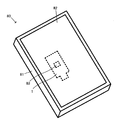
- an electronic device including a housing, an electronic component arranged inside the housing, and the vapor chamber arranged in the electronic component.
- Another aspect of the present disclosure is a sheet for a vapor chamber having a hollow portion into which a working fluid is to be injected, wherein the hollow portion includes a first flow path and a liquid flow path portion adjacent to the first flow path.
- the liquid flow path portion is provided with a second flow path in both the thickness directions of the vapor chamber, and is composed of three stacked sheets. Of the three sheets, the sheet arranged in the center is the sheet. It penetrates in the thickness direction of the sheet and extends along the sheet surface to form the first flow path, and the second flow path is provided on both sides of the liquid flow path portion of the sheet arranged in the center in the thickness direction. It is a sheet for a vapor chamber.
- a vapor chamber in which a working fluid is sealed in a closed space, wherein the closed space is provided with a first flow path and a liquid flow path portion adjacent to the first flow path.
- the part is provided with a second flow path and a heat insulating part, and the heat insulating part does not communicate with the first flow path and the second flow path, and consists of three stacked sheets, which are arranged in the center of the three sheets.
- the sheet penetrates in the thickness direction of the sheet and extends along the sheet surface to form the first flow path, and the second sheet is placed on one surface of the liquid flow path portion of the sheet arranged in the center in the thickness direction.
- It is a vapor chamber provided with a flow path and a heat insulating portion on the other side surface.
- an electronic device including a housing, an electronic component arranged inside the housing, and the vapor chamber arranged in the electronic component.
- Another aspect of the present disclosure is a sheet for a vapor chamber having a hollow portion into which a working fluid is to be injected, wherein the hollow portion includes a first flow path and a liquid flow path portion adjacent to the first flow path.
- the liquid flow path portion is provided with a second flow path and a heat insulating part, and the heat insulating part does not communicate with the first flow path and the second flow path, and is composed of three stacked sheets, out of the three sheets.
- the sheet arranged in the center penetrates in the thickness direction of the sheet and extends along the sheet surface to form the first flow path, and one side of the liquid flow path portion of the sheet arranged in the center in the thickness direction.
- This is a vapor chamber sheet provided with a second flow path on the surface of the surface and a heat insulating portion on the other surface.
- Another aspect of the present disclosure is a vapor chamber in which a working fluid is sealed in a closed space, wherein the closed space is provided with a first flow path and a liquid flow path portion adjacent to the first flow path.
- the portion is provided with a second flow path and an introduction portion that protrudes toward the first flow path side at the boundary surface with the first flow path, and the introduction portion is a second flow path from the top that protrudes most toward the first flow path side. It has an introduction surface extending toward, and consists of three stacked sheets, of which the centrally arranged sheet penetrates in the thickness direction of the sheet and along the sheet surface.
- Another aspect of the present disclosure is a sheet for a vapor chamber having a hollow portion into which a working fluid is to be injected, wherein the hollow portion includes a first flow path and a liquid flow path portion adjacent to the first flow path.
- the liquid flow path portion is provided with an introduction portion that protrudes toward the first flow path side at the boundary surface with the second flow path and the first flow path, and the introduction portion is provided from the top that protrudes most toward the first flow path side. It has an introduction surface extending toward the second flow path, and is composed of three stacked sheets. Of the three sheets, the sheet arranged in the center penetrates in the thickness direction of the sheet and is a sheet.
- a sheet for a vapor chamber which extends along a surface to form a first flow path and has a second flow path provided on at least one surface in the thickness direction of the liquid flow path portion of the sheet arranged in the center. ..
- Another aspect of the present disclosure is a vapor chamber in which a working fluid is sealed in a closed space, wherein the closed space is provided with a first flow path and a liquid flow path portion adjacent to the first flow path.
- the portion is provided with a second flow path in at least one of the thickness directions of the vapor chamber, and the first sheet, the second sheet, and the third sheet arranged between the first sheet and the second sheet are laminated.
- the third sheet penetrates in the thickness direction of the sheet and extends along the sheet surface to form the first flow path, and at least one of the first sheet and the second sheet is on the third sheet side.
- the inner sheet and the reinforcing sheet on the side opposite to the third sheet side are laminated, and the proof stress of the reinforcing sheet is higher than the proof stress of the inner sheet, which is a vapor chamber.
- Another aspect of the present disclosure is a vapor chamber in which a working fluid is sealed in a closed space, wherein the closed space is provided with a first flow path and a liquid flow path portion adjacent to the first flow path.
- the portion is provided with a second flow path in at least one of the thickness directions of the vapor chamber, and the first sheet, the second sheet, and the third sheet arranged between the first sheet and the second sheet are laminated.
- the third sheet penetrates in the thickness direction of the sheet and extends along the sheet surface to form the first flow path, and at least one of the first sheet and the second sheet is on the third sheet side.
- the inner sheet, the reinforcing sheet on the side opposite to the third sheet side, and the barrier sheet arranged between the inner sheet and the reinforcing sheet are laminated, and the proof stress of the reinforcing sheet is higher than the proof stress of the inner sheet.
- the barrier sheet is a vapor chamber containing at least one of tungsten, titanium, tantalum and molybdenum.
- the heat transport capacity of the vapor chamber can be enhanced.
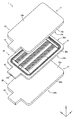
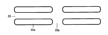
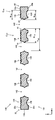
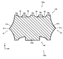
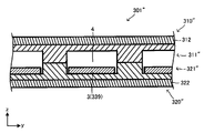
- FIG. 1 is a perspective view of the vapor chamber 1.
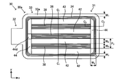
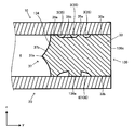
- FIG. 2 is an exploded perspective view of the vapor chamber 1.
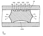
- FIG. 3 is a view of the third sheet 30 as viewed from the z direction.
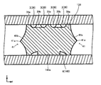
- FIG. 4 is a view seen from the opposite side of FIG.
- FIG. 5 is a cross-sectional view of the third sheet 30.
- FIG. 6 is another cross-sectional view of the third sheet 30.
- 7 (a) and 7 (b) are cross-sectional views focusing on the outer peripheral liquid flow path portion 34.
- FIG. 8 is an enlarged view of a part of the outer peripheral liquid flow path portion 34 when viewed from the z direction.
- FIG. 9 is an enlarged view of a part of the outer peripheral liquid flow path portion of another example when viewed from the z direction.
- FIG. 10 is a diagram illustrating an outer peripheral liquid flow path portion of another example.
- FIG. 11 is a diagram illustrating an outer peripheral liquid flow path portion of another example.
- FIG. 12 is a diagram illustrating an outer peripheral liquid flow path portion of another example.
- 13 (a) and 13 (b) are cross-sectional views focusing on the inner liquid flow path portion 38.
- FIG. 14 is an enlarged view of a part of the inner liquid flow path portion 38 when viewed from the z direction.
- FIG. 15 is a cross-sectional view of the vapor chamber 1.
- FIG. 16 is another cross-sectional view of the vapor chamber 1.
- 17 (a) and 17 (b) are enlarged cross-sectional views of a part of FIG.
- FIG. 18 (a) and 18 (b) are enlarged cross-sectional views of a part of FIG.
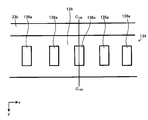
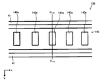
- FIG. 19 is a diagram illustrating an electronic device 50.
- FIG. 20 is a diagram illustrating the flow of the working fluid. It is a figure explaining the example by four sheets.
- FIG. 22 is an exploded perspective view of the vapor chamber 51 according to the second embodiment.
- FIG. 23 is a diagram illustrating a closed space of the vapor chamber 51.
- FIG. 24 is a cross-sectional view of the vapor chamber 51.
- FIG. 25 is an enlarged view of a part of FIG. 24.
- FIG. 26 is a perspective view of the vapor chamber 101.
- FIG. 27 is an exploded perspective view of the vapor chamber 101.
- FIG. 28 is a view of the third sheet 130 as viewed from the z direction.
- FIG. 29 is a view seen from the opposite side of FIG. 28.
- FIG. 30 is a cross-sectional view of the third sheet 130.
- FIG. 31 is another cross-sectional view of the third sheet 130.
- FIG. 32 is a cross-sectional view focusing on the outer peripheral liquid flow path portion 134.
- FIG. 33 is a diagram illustrating the outer peripheral liquid flow path portion 134.
- FIG. 34 is a cross-sectional view of a portion where the pillar 136a is arranged.
- FIG. 35 is a cross-sectional view focusing on the inner liquid flow path portion 138.
- FIG. 36 is a diagram illustrating an inner liquid flow path portion 138.
- FIG. 37 is a cross-sectional view of a portion where the pillar 140a is arranged.
- FIG. 38 is a cross-sectional view of the vapor chamber 101.
- FIG. 39 is another cross-sectional view of the vapor chamber 101.
- FIG. 40 is an enlarged view of a part of FIG. 38.
- FIG. 41 is an enlarged cross-sectional view of a portion where the pillar 136a is arranged.
- FIG. 42 is an enlarged view of a part of FIG. 38.
- FIG. 43 is an enlarged cross-sectional view of the portion where the pillar 140a is arranged.
- FIG. 44 is a diagram illustrating another form.
- FIG. 45 is a diagram illustrating another form.
- FIG. 46 is a diagram illustrating another form.
- FIG. 47 is a diagram illustrating another form.
- FIG. 50 is a diagram illustrating a preferred form in a cross section.
- 51 (a) and 51 (b) are diagrams for explaining the introduction portion of another form.
- 52 (a) and 52 (b) are diagrams for explaining the introduction portion of another form.
- 53 (a) and 53 (b) are diagrams for explaining the introduction portion of another form.
- 54 (a) and 54 (b) are diagrams for explaining the introduction portion of another form.
- FIGS. 55 (a) and 55 (b) are diagrams illustrating an introduction portion of another form.
- FIG. 58 is a cross-sectional view of the vapor chamber 301.
- FIG. 59 is a diagram illustrating a manufacturing process of the vapor chamber 301.
- FIG. 60 is a diagram illustrating a manufacturing process of the vapor chamber 301.
- FIG. 61 is a diagram illustrating a manufacturing process of the vapor chamber 301.
- FIG. 62 is a diagram illustrating a manufacturing process of the vapor chamber 301.
- FIG. 63 is a diagram illustrating a manufacturing process of the vapor chamber 301.
- FIG. 64 is a diagram illustrating a manufacturing process of the vapor chamber 301.
- FIG. 65 is a cross-sectional view of the vapor chamber 301'.
- FIG. 66 is a cross-sectional view of the vapor chamber 301 ”.
- FIG. 67 is a cross-sectional view of the vapor chamber 401.
- FIG. 68 is a diagram illustrating an inner liquid flow path portion 538 in the vapor chamber 501.
- FIG. 69 is a diagram illustrating a form of a pair of liquid flow path convex portions shown in FIG. 68.
- FIG. 70 is a diagram illustrating the operation of the pair of liquid flow path convex portions shown in FIG. 69.
- FIG. 71 is a diagram illustrating an actual form of the liquid flow path convex portion shown in FIG. 68.
- FIG. 72 is a diagram illustrating an inner liquid flow path portion 538'in the vapor chamber 501'.
- FIG. 73 is a diagram illustrating an inner liquid flow path portion 538 "in the vapor chamber 501".
- the shapes of a plurality of parts that can be expected to have the same function are regularly described, but the function should be expected without being bound by a strict meaning.
- the shapes of the portions may be different from each other as long as they can be formed.
- the boundary line indicating the joint surface between members is shown by a simple straight line for convenience, but it is not limited to a strict straight line, and a desired joint performance can be expected.
- the shape of the boundary line is arbitrary as long as it is possible.
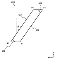
- FIG. 1 shows an external perspective view of the vapor chamber 1 according to the first embodiment
- FIG. 2 shows an exploded perspective view of the vapor chamber 1.
- Arrows (x, y, z) indicating the directions corresponding to the three-dimensional Cartesian coordinate system are also displayed in these figures and each of the figures shown below for convenience as necessary.
- the in-plane direction of xy is the plate surface direction of the vapor chamber 1 which is plate-shaped
- the z direction is the thickness direction.
- the vapor chamber 1 of the present embodiment has a first sheet 10, a second sheet 20, and a third sheet 30 (sometimes referred to as “intermediate sheet 30”). ing. Then, as will be described later, these sheets are overlapped and joined (diffusion joining, brazing, etc.) so that the shape of the third sheet 30 is formed between the first sheet 10 and the second sheet 20. It becomes a sheet for a vapor chamber in which a hollow portion based on the base is formed. Then, when the working fluid is sealed in this hollow portion, it becomes a closed space 2 (see, for example, FIG. 15) and becomes a vapor chamber 1.
- the first sheet 10 is a sheet-like member as a whole in which the front and back surfaces (one and the other surface in the thickness direction, the inner surface 10a and the outer surface 10b) are flat.
- the first sheet 10 is composed of flat surfaces on both the front and back surfaces, and forms a thickness by passing a flat inner surface 10a, a flat outer surface 10b opposite to the inner surface 10a, and the inner surface 10a and the outer surface 10b.
- the end face 10c is provided.
- the first sheet 10 includes a main body 11 and an injection unit 12.
- the main body 11 is a sheet-like portion that forms a hollow portion and a closed space, and in this embodiment, it is a rectangle whose corners are arcuate (having a so-called R) in a plan view.
- the main body 11 of the first sheet 10 has a quadrangular shape as in this embodiment, and may have a shape required for each vapor chamber. For example, it may be circular, elliptical, triangular, other polygonal, and a shape having a bent portion, for example, L-shaped, T-shaped, crank-shaped, U-shaped, or the like. Further, the shape may be a combination of at least two of these.
- the injection portion 12 is a portion for injecting the working fluid into the formed hollow portion, and in this embodiment, it has a rectangular sheet shape in a plan view protruding from one side of the main body 11 which is a rectangular shape in a plan view.
- the thickness of such a first sheet 10 is not particularly limited, but is preferably 1.0 mm or less, and may be 0.75 mm or less, or 0.5 mm or less. On the other hand, this thickness is preferably 0.01 mm or more, may be 0.05 mm or more, or may be 0.1 mm or more.
- the range of the thickness may be determined by a combination of any one of the plurality of upper limit candidate values and one of the plurality of lower limit candidate values. Further, the thickness range may be determined by a combination of any two of a plurality of upper limit candidate values or by any combination of a plurality of lower limit candidate values. This makes it possible to increase the number of situations in which it can be applied as a thin vapor chamber.
- the material constituting the first sheet 10 is not particularly limited, but a metal having high thermal conductivity is preferable. Examples thereof include copper and copper alloys. However, not necessarily a metallic material, for example AlN, Si 3 N 4, or, ceramics, such as Al 2 O 3, which resin may be such as polyimide or epoxy. Further, a material obtained by laminating two or more kinds of materials in one sheet may be used, or the materials may be different depending on the part.
- the first sheet 10 may be a single layer, or a plurality of sheets may be laminated.
- a sheet (clad material) in which a plurality of layers having different strengths are laminated may be used.
- the second sheet 20 is also a sheet-like member as a whole whose front and back surfaces are flat.
- the second sheet 20 is composed of flat surfaces on both the front and back surfaces, and forms a thickness by passing the flat inner surface 20a, the flat outer surface 20b opposite to the inner surface 20a, and the inner surface 20a and the outer surface 20b.
- the end face 20c is provided.
- the second sheet 20 also includes a main body 21 and an injection unit 22 like the first sheet 10.
- the second sheet 20 can be considered in the same manner as the first sheet 10.
- the thickness and material of the second sheet 20 do not have to be the same as those of the first sheet 10, and may be configured differently.
- the second sheet 20 may also be a single layer, or a plurality of sheets may be laminated.
- a sheet (clad material) in which a plurality of layers having different strengths are laminated may be used.
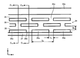
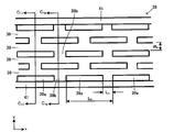
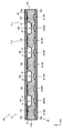
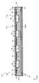
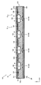
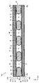
- the third sheet 30 is a sheet sandwiched and stacked between the inner surface 10a of the first sheet 10 and the inner surface 20a of the second sheet 20, and has a structure for the closed space 2 in which the working fluid moves. It is equipped. 3 and 4 show a plan view (viewed from the z direction) of the third sheet 30.
- FIG. 3 is a view of the surface stacked on the first sheet 10
- FIG. 4 is a view of the surface stacked on the second sheet 20.
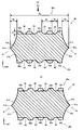
- the cross-sectional view taken along the line indicated by C 1 -C 1 3 in FIG. 5 it is shown a cross-sectional view taken along the line indicated by C 2 -C 2 in FIG. 3, respectively in FIG.
- hatching (diagonal line) is attached to the part related to the cut surface, and hatching is attached to the part not related to the cut surface and appearing in the cross-sectional view that needs to be displayed. It is displayed without. The same applies to the following drawings.
- the third sheet 30 may also be a single layer, or a plurality of sheets may be laminated.
- the plurality of sheets may be laminated and then formed into the following form, or the plurality of sheets may be individually processed and then overlapped to form the following form. You may.
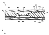
- the third sheet 30 includes a first surface 30a that overlaps the inner surface 10a of the first sheet 10, a second surface 30b that overlaps the inner surface 20a of the second sheet 20, and the first surface 30a and the second surface 30b. It is provided with an end face 30c that is passed to form a thickness. Therefore, the first surface 30a appears in FIG. 3, and the second surface 30b appears in FIG. 4, respectively.
- the third sheet 30 includes a main body 31 and an injection unit 32.
- the main body 31 is a hollow portion in the sheet for the vapor chamber and a sheet-like portion forming a closed space in the vapor chamber 1, and in this embodiment, it is a rectangle whose corners are arcuate (having a so-called R) in a plan view. ..
- the main body 31 has a quadrangular shape as in this embodiment, and can also have a shape required as a vapor chamber. For example, it may be circular, elliptical, triangular, other polygonal, and a shape having a bent portion, for example, L-shaped, T-shaped, crank-shaped, U-shaped, or the like. Further, the shape may be a combination of at least two of these.
- the injection portion 32 is a portion for injecting the working fluid into the formed hollow portion, and in this embodiment, it has a rectangular sheet shape in a plan view protruding from one side of the main body 31 which is a rectangular shape in a plan view.
- the injection unit 32 is provided with a groove 32a leading from the end surface 30c to the main body 31 on the second surface 30b side.
- the thickness of the third sheet 30 can be 0.03 mm or more and 0.8 mm or less. However, the thickness of the third sheet 30 is preferably thicker than that of the first sheet 10 and the second sheet 20. As a result, the cross section of the steam flow path 4 described later can be made large, and the working fluid can move more smoothly.
- the material of the third sheet 30 can be considered in the same manner as the first sheet 10 and the second sheet 20.
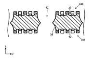
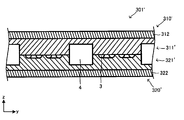
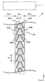
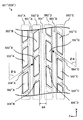
- the main body 31 is formed with a structure for refluxing the working fluid. Specifically, the main body 31 is provided with an outer peripheral joint portion 33, an outer peripheral liquid flow path portion 34, an inner liquid flow path portion 38, a vapor flow path groove 42, and a vapor flow path communication groove 44. There is.
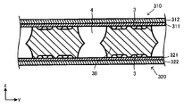
- the vapor chamber 1 of this embodiment is the first flow path through which the vapor of the working fluid passes through the steam flow path 4 (see FIG. 15 and the like) and the second flow path through which the working fluid is condensed and liquefied.
- a condensate flow path 3 (see FIG. 18 and the like) is provided.
- the vapor flow path groove 42 of the third sheet 30 forms the vapor flow path 4, and the liquid flow path groove 35, the liquid flow path groove 36 (see FIG. 7 and the like) provided in the outer peripheral liquid flow path portion 34, and
- the liquid flow path groove 39 and the liquid flow path groove 40 (see FIGS. 13 (a), 13 (b), etc.) provided in the inner liquid flow path portion 38 form the condensate flow path 3.
- the outer peripheral joint portion 33 is a portion provided along the outer circumference of the main body 31, and includes an outer peripheral joint surface 33a provided on the first surface 30a of the main body 31 and an outer peripheral joint surface 33b provided on the second surface 30b. ing.
- the outer peripheral joint surface 33a overlaps the outer peripheral portion of the inner surface 10a of the first sheet 10
- the outer peripheral joint surface 33b overlaps the outer peripheral portion of the inner surface 20a of the second sheet 20, and each is joined (diffusion bonding, brazing, etc.).
- a hollow portion based on the shape of the third sheet 30 is formed between the first sheet 10 and the second sheet 20, and the working fluid is sealed therein to form a closed space.
- the width W 1 is preferably 3.0 mm or less, and may be 2.5 mm or less, or 2.0 mm or less. If the width W 1 is larger than 3.0 mm, the internal volume of the closed space becomes small, and there is a risk that the vapor flow path and the condensate flow path cannot be sufficiently secured.
- the width W 1 is preferably 0.1 mm or more, may be 0.4 mm or more, or may be 0.8 mm or more.
- the joining area may be insufficient when the positions of the sheets are displaced during joining.
- the range of the width W 1 may be determined by a combination of any one of the plurality of upper limit candidate values and one of the plurality of lower limit candidate values. Further, the range of the width W 1 may be defined by a combination of any two of a plurality of upper limit candidate values or an arbitrary combination of a plurality of lower limit candidate values.
- the width of the outer peripheral joint surface 33a and the width of the outer peripheral joint surface 33b are both indicated by W 1 , the width of the outer peripheral joint surface 33a and the width of the outer peripheral joint surface 33b do not necessarily have to be the same and are different. It may be the width.
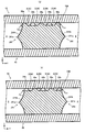
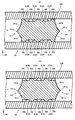
- the outer peripheral liquid flow path portion 34 functions as a liquid flow path portion, and is a portion forming a part of the condensate flow path 3 which is a second flow path through which the working fluid is condensed and liquefied.
- FIG. 7 (a), FIG. 7 (b) showing an enlarged portion indicated by an arrow C 3 of FIG.
- the (viewed from the z-direction) of the perimetric liquid flow path 34 seen from the direction indicated by the arrow C 4 in FIG. 7 a plan view, of the Figure 8 showing an enlarged view. That is, FIG. 8 shows a part of the outer peripheral liquid flow path portion 34 seen from the first surface 30a.
- FIG. 8 shows a part of the outer peripheral liquid flow path portion 34 seen from the first surface 30a.
- FIG. 7 (a) is a C 15 -C 15 arrow sectional view of FIG. 8
- FIG. 7 (b) is a cross-sectional view taken along C 16 -C 16 of Figure 8.
- FIG. 7A is a cross section in which the convex portion 35a is arranged on the introduction portion 37 side
- FIG. 7B is a cross section in which the communication opening 35b is arranged on the introduction portion 37 side.
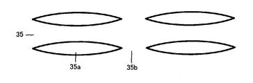
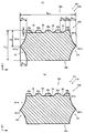
- the outer peripheral liquid flow path portion 34 is a portion of the main body 31 formed along the inside of the outer peripheral joint portion 33 and provided along the outer circumference of the portion that becomes the closed space 2. Further, each of the first surface 30a and the second surface 30b of the outer peripheral liquid flow path portion 34 has a liquid flow path groove 35 (first surface 30a side) and a liquid which are a plurality of grooves extending along the outer peripheral direction of the main body 31.
- the flow path groove 36 (second surface 30b side) is formed, and the plurality of liquid flow path grooves 35 and the liquid flow path groove 36 are determined in a direction different from the direction in which the liquid flow path groove 35 and the liquid flow path groove 36 extend. Are arranged at intervals of.
- the convex portion 35a between the liquid flow path groove 35 which is a concave portion and the liquid flow path groove 35 on the first surface 30a side. Is formed by repeating unevenness.
- the liquid flow path groove 36, which is a concave portion, and the convex portion 36a, which is between the liquid flow path groove 36, are formed by repeating unevenness. That is, in the present embodiment, liquid flow path grooves serving as the condensate flow path 3 are provided on one side and the other side (front and back sides) in the thickness direction (z direction).
- each of the first surface 30a and the second surface 30b is provided with a plurality of liquid flow path grooves 35 and liquid flow path grooves 36, so that the total flow path of the condensed liquid flow path 3 as a whole is provided.
- the cross-sectional area is secured to an appropriate size, the condensate of the required flow rate can be flowed, and the depth and width of the liquid flow path groove 35 and the liquid flow path groove 36 per one are reduced, whereby the first A large capillary force can be utilized by reducing the flow path cross-sectional area of the condensate flow path 3 (see FIGS. 17 (a), 17 (b), etc.) which is the two flow paths.
- the depth and width may be changed between one and the other (front and back), that is, the liquid flow path groove 35 and the liquid flow path groove 36, respectively. According to this, the flow rate and the capillary force can be adjusted independently according to the final product.
- the liquid flow path groove 35 and the liquid flow path groove 36 are grooves, they have a bottom portion in the cross-sectional shape thereof, and the opposite side facing the bottom portion is open. As will be described later, when the first sheet 10 and the second sheet 20 are overlapped with the third sheet 30, this opening is closed to form the condensate flow path 3.
- the liquid flow path groove 35 and the liquid flow path groove 36 have a semi-elliptical cross section.
- the cross-sectional shape is not limited to a semi-elliptical shape, and may be a quadrangle such as a circle, a rectangle, a square, a trapezoid, another polygon, or a shape obtained by combining any one or more of these. ..
- the adjacent liquid flow path grooves 35 are communicated with each other by the communication openings 35b at predetermined intervals.
- the equalization of the amount of condensate is promoted among the plurality of liquid flow path grooves 35, the condensate can flow efficiently, and the working fluid can be smoothly returned.
- the liquid flow path groove 35, the convex portion 35a, and the communication opening 35b will be described, but the liquid flow path groove 36 and the convex portion provided on the second surface 30b side will be described.
- the same can be considered for the portion 36a, in which a communication opening 36b (not shown) is provided, and can be considered in the same manner as the liquid flow path groove 35, the convex portion 35a, and the communication opening 35b.
- communication openings 35b may be arranged at different positions in the direction in which the liquid flow path groove 35 extends with the groove of one liquid flow path groove 35 interposed therebetween. That is, the convex portions 35a and the communication openings 35b are alternately arranged along the direction orthogonal to the direction in which the liquid flow path groove extends.
- the present invention is not limited to this, and for example, as shown in FIG. 9, the communication opening so as to face the same position in the direction in which the liquid flow path groove 35 extends across the groove of one liquid flow path groove 35. 35b may be arranged.
- FIGS. 10 to 12 show one liquid flow path groove 35, two convex portions 35a sandwiching the liquid flow path groove 35, and one communication opening 35b provided in each convex portion 35a from the same viewpoint as in FIG. The figure is shown.
- the shape of the convex portion 35a is different from the example of FIG. 8 from the viewpoint (plan view). That is, in the convex portion 35a shown in FIG. 8, the width thereof is the same as that of the other portions and is constant even at the end portion where the communication opening 35b is formed.
- FIG. 10 to 12 is formed so that the width thereof is smaller than the maximum width of the convex portion 35a at the end portion where the communication opening 35b is formed. .. More specifically, FIG. 10 shows an example in which the corners are arcuate at the ends and R is formed at the corners to reduce the width of the ends, and FIG. 11 shows an example in which the ends are semicircular. An example in which the width of the end portion is reduced, and FIG. 12 is an example in which the end portion is tapered so as to be sharpened.
- communication is formed by forming the width of the convex portion 35a at the end where the communication opening 35b is formed so as to be smaller than the maximum width of the convex portion 35a.
- the working fluid can easily move through the opening 35b, and the working fluid can easily move to the adjacent condensate flow path.
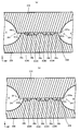
- an introduction portion 37 is provided in the outer peripheral liquid flow path portion 34.
- the introduction portion 37 is a portion formed on the interface with the steam flow path groove 42, and is a portion protruding toward the steam flow path groove 42 side.
- the most protruding top portion 37a is provided at the center in the thickness direction (z direction), and the outer peripheral liquid flow is viewed in cross section from the top portion 37a toward the first surface 30a and the second surface 30b side (z direction).
- An introduction surface 37b having a concave arc shape is provided on the road portion 34 side.
- the form of the introduction portion 37 is not limited to this, and the position of the top portion 37a may be any of the z directions, and the introduction surface 37b may be a straight line in cross section or a curved line that is not arcuate. Further, the top portion 37a may be a point in a cross-sectional view and may have a length.
- the condensate easily collects on the introduction surface 37b due to the shape as described above, and the working fluid moves smoothly between the condensate flow path 3 and the vapor flow path 4 through the introduction unit 37. Therefore, the heat transport capacity can be further increased.
- the outer peripheral liquid flow path portion 34 having the above configuration may further have the following configuration.
- the drawing is referred to here, only the first surface 30a side will be described, but the second surface 30b side (liquid flow path groove 36, convex portion 36a, and communication opening 36b) should be considered in the same manner. Can be done. However, this does not mean that the shape of the first surface 30a side and the shape of the second surface 30b side need to be the same, and the first surface 30a side and the second surface 30b side The shapes of the above may be the same or different.
- the width of the outer peripheral liquid flow path portion 34 (the size in the direction in which the liquid flow path groove 35 and the liquid flow path groove 36 are arranged) shown by W 2 in FIGS. 3 to 5 and 7 (a) is the vapor chamber.
- the width W 2 is preferably 3.0 mm or less, and may be 1.5 mm or less, or 1.0 mm or less. If the width W 2 exceeds 3.0 mm, there is a risk that sufficient space for the inner liquid flow path and vapor flow path cannot be secured.
- the width W 2 is preferably 0.05 mm or more, and may be 0.1 mm or more, or 0.2 mm or more.
- the range of the width W 2 may be determined by a combination of any one of the plurality of upper limit candidate values and one of the plurality of lower limit candidate values. Further, the range of the width W 2 may be defined by a combination of any two of a plurality of upper limit candidate values or an arbitrary combination of a plurality of lower limit candidate values.
- the width of the outer peripheral liquid flow path portion 34 on the first surface 30a side and the width on the second surface 30b side are both indicated by W 2 , but the width of the outer peripheral joining surface 33a and the width of the outer peripheral joining surface 33b are shown. It does not have to be the same, but may have different widths.
- the groove width shown in W 3 in FIG. 8 (a size in the direction of liquid flow path grooves 35 are arranged, the width of the opening surface of the groove) is a 1000 ⁇ m or less It is preferably 500 ⁇ m or less, or 200 ⁇ m or less.
- the width W 3 is preferably 20 ⁇ m or more, and may be 45 ⁇ m or more, or 60 ⁇ m or more.
- the range of the width W 3 may be determined by a combination of any one of the plurality of upper limit candidate values and one of the plurality of lower limit candidate values.
- the range of the width W 3 may be defined by any combination of a plurality of upper limit candidate values or any combination of a plurality of lower limit candidate values.
- the depth of the groove indicated by D 1 FIGS. 7 (a) is preferably 200 ⁇ m or less, may also be 150 ⁇ m or less, it may be 100 ⁇ m or less.
- the depth D 1 is preferably 5 ⁇ m or more, and may be 10 ⁇ m or more, or 20 ⁇ m or more.
- the range of the depth D 1 may be determined by a combination of any one of the plurality of upper limit candidate values and one of the plurality of lower limit candidate values.
- the range of the depth D 1 may be defined by any combination of a plurality of upper limit candidate values or any combination of a plurality of lower limit candidate values.
- the aspect ratio (aspect ratio) in the flow path cross section represented by the value obtained by dividing the groove width W 3 by the depth D 1 is larger than 1.0. Is preferable. This ratio may be 1.5 or more, or 2.0 or more. Alternatively, the aspect ratio may be less than 1.0. This ratio may be 0.75 or less, or 0.5 or less. Among them, W 3 is preferably larger than D 1 from the viewpoint of manufacturing, and the aspect ratio is preferably larger than 1.3 from this viewpoint.
- the pitch of the liquid flow path grooves 35 adjacent in the plurality of liquid flow path grooves 35 shown in P 1 in FIG. 7 (a) is preferably not more than 1100 .mu.m, it may be less 550 .mu.m, 220 .mu.m or less It may be.
- the pitch P 1 is preferably 30 ⁇ m or more, may be 55 ⁇ m or more, or may be 70 ⁇ m or more.
- the range of the pitch P 1 may be determined by a combination of any one of the plurality of upper limit candidate values and one of the plurality of lower limit candidate values.
- the range of the pitch P 1 may be defined by a combination of any two of a plurality of upper limit candidate values or an arbitrary combination of a plurality of lower limit candidate values.
- the size of the opening along the liquid flow path grooves 35 shown extends in L 1 in FIG. 8 is preferably not more than 1100 .mu.m, it may be less 550 .mu.m, 220 .mu.m or less It may be.
- the size L 1 is preferably 30 ⁇ m or more, 55 ⁇ m or more, or 70 ⁇ m or more.
- the range of the magnitude L 1 may be determined by a combination of any one of the plurality of upper limit candidate values and one of the plurality of lower limit candidate values. Further, the range of the size L 1 may be defined by a combination of any two of a plurality of upper limit candidate values or an arbitrary combination of a plurality of lower limit candidate values.
- the pitch of the communication opening portion 35b adjacent in the direction in which the liquid passage grooves 35 shown by L 2 in FIG. 8 extends is preferably not more than 2700Myuemu, may be less 1800 .mu.m, equal to or less than 900 ⁇ m May be good.
- the pitch L 2 is preferably 60 ⁇ m or more, and may be 110 ⁇ m or more, or 140 ⁇ m or more.
- the range of the pitch L 2 may be determined by a combination of any one of the plurality of upper limit candidate values and one of the plurality of lower limit candidate values. Further, the range of the pitch L 2 may be defined by a combination of any two of a plurality of upper limit candidate values or by any combination of a plurality of lower limit candidate values.
- protruded amount shown in W 4 in FIGS. 7 (a) is preferably 1000 ⁇ m or less, may also be 500 ⁇ m or less, 300 [mu] m It may be as follows.
- the protrusion amount W 4 is preferably 20 ⁇ m or more, and may be 45 ⁇ m or more, or 60 ⁇ m or more.
- the range of the protrusion amount W 4 may be determined by a combination of any one of the plurality of upper limit candidate values and one of the plurality of lower limit candidate values. Further, the range of the protrusion amount W 4 may be determined by combining any two of a plurality of upper limit candidate values or by any combination of a plurality of lower limit candidate values.
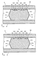
- the inner liquid flow path portion 38 also functions as a liquid flow path portion, and is a part of a condensate flow path 3 which is a second flow path through which the working fluid is condensed and liquefied, and a portion constituting the introduction portion 41. is there.
- FIG. 13 (a) showing an enlarged portion indicated by an arrow C 5 out of 5 in Figure 13 (b).
- the cross-sectional shape of the inner liquid flow path portion 38 also appears in FIGS. 13 (a) and 13 (b).
- FIG. 13 (a) showing an enlarged portion indicated by an arrow C 5 out of 5 in Figure 13 (b).
- FIG. 13 (a) is a C 17 -C 17 arrow sectional view of FIG. 14
- FIG. 13 (b) is a cross-sectional view taken along a C 18 -C 18 of Figure 14.
- FIG. 13A is a cross section in which the convex portion 39a is arranged on the introduction portion 41 side
- FIG. 13B is a cross section in which the communication opening 39b is arranged on the introduction portion 41 side.
- the inner liquid flow path portion 38 is a portion of the main body 31 formed inside the annular ring of the outer peripheral liquid flow path portion 34.
- the inner liquid flow path portion 38 of the present embodiment extends in a direction (x direction) parallel to the long side of the rectangle in the plan view (when viewed from the z direction) of the main body 31, and a plurality of (three in this embodiment) inner liquids.
- the flow path portions 38 are arranged at predetermined intervals in a direction parallel to the short side (y direction).
- Liquid flow path groove 39 (first surface 30a side), which is a plurality of grooves extending in the direction in which the inner liquid flow path portion 38 extends, on each of the first surface 30a and the second surface 30b of the inner liquid flow path portion 38.
- the liquid flow path groove 40 (second surface 30b side) is formed, and the plurality of liquid flow path grooves 39 and the liquid flow path groove 40 are in a direction different from the direction in which the liquid flow path groove 39 and the liquid flow path groove 40 extend. Are arranged at predetermined intervals. Therefore, as can be seen from FIG.
- the liquid flow path groove 39 which is a recess on the first surface 30a side and the convex portion 39a between the liquid flow path grooves 39. Is formed by repeating unevenness.
- the liquid flow path groove 40 which is a concave portion, and the convex portion 40a, which is between the liquid flow path grooves 40, are formed by repeating unevenness. That is, in this embodiment, the liquid flow path groove serving as the condensate flow path 3 is provided on both one side and the other side (front and back) in the thickness direction (z direction).
- each of the first surface 30a and the second surface 30b is provided with a plurality of liquid flow path grooves 39 and liquid flow path grooves 40, so that the total flow path of the condensed liquid flow path 3 as a whole is provided.
- the cross-sectional area is secured to an appropriate size, the condensate of the required flow rate can be flowed, and the depth and width of each liquid flow path groove 39 and liquid flow path groove 40 are reduced to reduce the depth and width of the second flow.
- a large capillary force can be utilized by reducing the flow path cross-sectional area of the condensate flow path 3 (see FIG. 18 and the like), which is a path.
- the liquid flow path groove 39 and the liquid flow path groove 40 are grooves, they have a bottom portion in their cross-sectional shape, and the opposite side facing the bottom portion is open. As will be described later, when the first sheet 10 and the second sheet 20 are overlapped with the third sheet 30, this opening is closed to form the condensate flow path 3.
- the liquid flow path groove 39 and the liquid flow path groove 40 have a semi-elliptical cross section.
- the cross-sectional shape is not limited to a semi-elliptical shape, and may be a quadrangle such as a circle, a rectangle, a square, a trapezoid, another polygon, or a shape obtained by combining any one or more of these. ..
- the adjacent liquid flow path grooves 39 are communicated with each other by the communication opening 39b at a predetermined interval.
- the equalization of the amount of condensate is promoted among the plurality of liquid flow path grooves 39, the condensate can flow efficiently, and the working fluid can be smoothly returned. Since the first surface 30a side is shown in FIG. 14, the liquid flow path groove 39, the convex portion 39a, and the communication opening 39b will be described, but the liquid flow path groove 40 and the convex portion provided on the second surface 30b side will be described.
- the portion 40a in which a communication opening 40b (not shown) is provided, and can be considered in the same manner as the liquid flow path groove 39, the convex portion 39a, and the communication opening 39b.
- the communication opening 39b similarly to the communication opening 35b described above, in the direction orthogonal to the direction in which the liquid flow path groove 39 and the liquid flow path groove 40 extend, following the example shown in FIG.
- the communication openings 39b may be arranged at the same position.
- the shape of the communication opening 39b and the convex portion 39a may be formed according to the examples of FIGS. 10 to 12.
- the introduction portion 41 is provided in the inner liquid flow path portion 38.
- the introduction portion 41 is a portion formed on the interface with the steam flow path groove 42, and is a portion protruding toward the steam flow path groove 42 side.
- the most protruding top portion 41a is provided at the center in the thickness direction (z direction), and the inner liquid flow is viewed in cross section from the top portion 41a toward the first surface 30a and the second surface 30b side (z direction).
- An introduction surface 41b having a concave arc shape is provided on the road portion 38 side.
- the form of the introduction portion 41 is not limited to this, and the position of the top portion 41a may be any of the z directions, and the introduction surface 41b may be a straight line in cross section or a curved line that is not arcuate. Further, the top portion 41a may be a point in cross section or may have a length.
- the condensate easily collects on the introduction surface 41b due to the shape as described above, and the working fluid moves smoothly between the condensate flow path 3 and the vapor flow path 4 through the introduction unit 41.
- the heat transport capacity can be further increased.
- the inner liquid flow path portion 38 having the above configuration is preferably further provided with the following configuration.
- the largest value is preferably 3000 ⁇ m or less, and may be 2000 ⁇ m or less, or 1500 ⁇ m or less.
- the width W 5 is preferably 100 ⁇ m or more, and may be 200 ⁇ m or more, or 400 ⁇ m or more.
- the range of the width W 5 may be determined by a combination of any one of the plurality of upper limit candidate values and one of the plurality of lower limit candidate values. Further, the range of the width W 5 may be defined by any combination of a plurality of upper limit candidate values or any combination of a plurality of lower limit candidate values.
- the pitch of the plurality of inner liquid flow path portion 38 shown in P 2 in FIG. 5 may be that it is less preferable 3500 ⁇ m or less 5000 .mu.m, may be not more than 3000 .mu.m.
- the pitch P 2 is preferably 200 ⁇ m or more, and may be 400 ⁇ m or more, or 800 ⁇ m or more.
- the range of the pitch P 2 may be determined by a combination of any one of the plurality of upper limit candidate values and one of the plurality of lower limit candidate values.
- the range of the pitch P2 may be defined by a combination of any two of a plurality of upper limit candidate values or by any combination of a plurality of lower limit candidate values.
- the inner liquid flow path portion 38 having the above configuration may further have the following configuration.
- the drawing is referred to here, only the first surface 30a side will be described, but the second surface 30b side (liquid flow path groove 40, convex portion 40a, and communication opening 40b) should be considered in the same manner. Can be done. However, this does not mean that the shape of the first surface 30a side and the shape of the second surface 30b side need to be the same, and the first surface 30a side and the second surface 30b side The shapes of the above may be the same or different.
- the width of the opening surface of the groove groove width shown in the W 6 in FIG. 14, 1000 .mu.m or less It may be 500 ⁇ m or less, and may be 200 ⁇ m or less.
- the width W 6 is preferably 20 ⁇ m or more, and may be 45 ⁇ m or more, or 60 ⁇ m or more.
- the range of the width W 6 may be determined by a combination of any one of the plurality of upper limit candidate values and one of the plurality of lower limit candidate values. Further, the range of the width W 6 may be defined by any combination of a plurality of upper limit candidate values or any combination of a plurality of lower limit candidate values.
- the depth of the liquid flow path groove 39 shown by D 2 in FIG. 13A is preferably 200 ⁇ m or less, preferably 150 ⁇ m or less, or 100 ⁇ m or less.
- the depth D 2 is preferably 5 ⁇ m or more, and may be 10 ⁇ m or more, or 20 ⁇ m or more.
- the range of the depth D 2 may be determined by a combination of any one of the plurality of upper limit candidate values and one of the plurality of lower limit candidate values. Further, the range of the depth D 2 may be defined by a combination of any two of a plurality of upper limit candidate values or an arbitrary combination of a plurality of lower limit candidate values.
- the aspect ratio (aspect ratio) in the flow path cross section represented by the value obtained by dividing the groove width W 6 by the depth D 2 may be larger than 1.0. preferable. It may be 1.5 or more, or 2.0 or more. Alternatively, it may be smaller than 1.0, 0.75 or less, or 0.5 or less.
- the groove width W 6 is preferably larger than the depth D 2 from the viewpoint of manufacturing, and the aspect ratio is preferably larger than 1.3 from this viewpoint.
- the pitch shown in FIG. 13 (a) to P 3 in the liquid flow path grooves 39 adjacent in the plurality of liquid flow path grooves 39 shown is preferably not more than 1100 .mu.m, it may be less 550 .mu.m, 220 .mu.m or less It may be.
- the pitch P 3 is preferably 30 ⁇ m or more, and may be 55 ⁇ m or more, or 70 ⁇ m or more.
- the range of the pitch P 3 may be determined by a combination of any one of the plurality of upper limit candidate values and one of the plurality of lower limit candidate values.
- the range of the pitch P 3 may be defined by a combination of any two of a plurality of upper limit candidate values or by any combination of a plurality of lower limit candidate values.
- the communication opening portion 39 b, at the indicated liquid flow path groove 39 direction of the opening size along extending L 3 in FIG. 14 is preferably not more than 1100 .mu.m, it may be less 550 .mu.m, It may be 220 ⁇ m or less.
- the size L 3 is preferably 30 ⁇ m or more, and may be 55 ⁇ m or more, or 70 ⁇ m or more.
- the range of the magnitude L 3 may be determined by a combination of any one of the plurality of upper limit candidate values and one of the plurality of lower limit candidate values. Further, the range of the size L 3 may be defined by any combination of a plurality of upper limit candidate values or any combination of a plurality of lower limit candidate values.
- the pitch of the communication opening portion 39b adjacent in the direction in which the liquid flow path groove 39 extends may be that it is less preferable 1800 ⁇ m or less 2700Myuemu, equal to or less than 900 ⁇ m May be good.
- the pitch L 4 is preferably 60 ⁇ m or more, and may be 110 ⁇ m or more, or 140 ⁇ m or more.
- the range of the pitch L 4 may be determined by a combination of any one of the plurality of upper limit candidate values and one of the plurality of lower limit candidate values. Further, the range of the pitch L 4 may be defined by a combination of any two of a plurality of upper limit candidate values or by any combination of a plurality of lower limit candidate values.
- the liquid flow path groove 35 and the liquid flow path groove 36, and the liquid flow path groove 39 and the liquid flow path groove 40 of the present embodiment described above are arranged at equal intervals and parallel to each other, but the present invention is limited to this. If the capillarity can be achieved, the pitches of the grooves may vary, and the grooves may not be parallel to each other.
- protrusion amount W 7 is preferably 20 ⁇ m or more, and may be 45 ⁇ m or more, or 60 ⁇ m or more.
- the range of the protrusion amount W 7 may be determined by a combination of any one of the plurality of upper limit candidate values and one of the plurality of lower limit candidate values. Further, the range of the protrusion amount W 7 may be determined by combining any two of a plurality of upper limit candidate values or by any combination of a plurality of lower limit candidate values.
- the steam flow path groove 42 is a portion through which the vaporized steam by evaporating the working fluid passes, and constitutes a part of the steam flow path 4 (see FIG. 15 and the like) which is the first flow path.
- 3 and 4 show the shape of the steam flow path groove 42 in a plan view
- FIG. 5 shows the cross-sectional shape of the steam flow path groove 42.
- the vapor flow path groove 42 is formed of a groove (slit) formed inside the annular ring of the outer peripheral liquid flow path portion 34 in the main body 31.
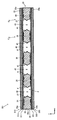
- the vapor flow path groove 42 of the present embodiment is formed between the adjacent inner liquid flow path portions 38 and between the outer peripheral liquid flow path portion 34 and the inner liquid flow path portion 38, and is viewed in a plan view of the main body 31. It is a rectangular groove extending in the direction parallel to the long side (x direction).
- a plurality of (four in this embodiment) steam flow path grooves 42 are arranged in a direction parallel to the short side (y direction).
- the steam flow path groove 42 of the present embodiment is configured to communicate the first surface 30a and the second surface 30b side of the third sheet 30, that is, it is a slit-shaped groove, and the thickness of the third sheet 30 is increased. It penetrates in the direction, opens to the first surface 30a and the second surface 30b, and extends along the sheet surfaces (first surface 30a, second surface 30b) of the third sheet 30. Therefore, as can be seen from FIG. 5, the third sheet 30 has a shape in which the outer peripheral liquid flow path portion 34, the inner liquid flow path portion 38, and the vapor flow path groove 42 are alternately repeated in the y direction.
- the steam flow path groove 42 having such a configuration can further include the following configuration.
- the width of the vapor flow path groove 42 shown by W 8 in FIGS. 3, 4, and 5 (the size in the direction in which the inner liquid flow path portion 38 and the steam flow path groove 40 are arranged, and the opening of the steam flow path groove).
- width in the plane is at least the above-mentioned liquid flow path grooves 35 and the liquid flow path groove 37 width W 3 of, and is larger than the width W 6 of the liquid flow path grooves 39 and the liquid passage grooves 40, below 2500 ⁇ m It is preferably 2000 ⁇ m or less, and may be 1500 ⁇ m or less.
- the width W 8 is preferably 100 ⁇ m or more, and may be 200 ⁇ m or more, or 400 ⁇ m or more.
- the range of the width W 8 may be determined by a combination of any one of the plurality of upper limit candidate values and one of the plurality of lower limit candidate values. Further, the range of the width W 8 may be defined by any combination of a plurality of upper limit candidate values or any combination of a plurality of lower limit candidate values.
- the pitch of the vapor flow path groove 42 is usually determined by the pitch of the inner liquid flow path portion 38.
- the cross-sectional shape of the steam flow path groove 42 is based on the introduction portion 37 and the introduction portion 41, but when the introduction portion 41 is not provided, a quadrangle such as a rectangle, a square, a trapezoid, a triangle, or a triangle.
- the shape may be a combination of any one or more of these.
- the steam flow path communication groove 44 is a groove for communicating a plurality of steam flow path grooves 42.
- the steam flow path communication groove 44 is a groove for communicating a plurality of steam flow path grooves 42.
- the vapor flow path communication groove 44 of the present embodiment includes the inner liquid flow path portion 38, both ends in the direction in which the vapor flow path groove 42 extends, and the outer liquid flow path. It is formed between the portion 34 and the portion 34.
- the steam flow path communication groove 44 is formed so as to communicate the adjacent steam flow path grooves 42.
- the steam flow path communication groove 44 has a groove 44a on the first surface 30a side and a groove 44b on the second surface 30b side, and is connected between the groove 44a and the groove 44b.
- the part 44c is provided.
- the connecting portion 44c connects the inner liquid flow path portion 38 and the outer peripheral liquid flow path portion 33 and holds the inner liquid flow path portion 38. Further, as shown in FIGS.
- the steam flow path communication groove 44 may be connected to a plurality of steam flow path grooves 42, and its shape is not particularly limited, but for example, the following configuration can be provided.
- the width of the steam flow path communication groove 44 (the size in the direction orthogonal to the communication direction and the width on the opening surface of the groove) shown by W 9 in FIGS. 3, 4 and 6 is preferably 2500 ⁇ m or less. , 2000 ⁇ m or less, or 1500 ⁇ m or less.
- the width W 9 is preferably 100 ⁇ m or more, may be 200 ⁇ m or more, or may be 400 ⁇ m or more.
- the range of the width W 9 may be determined by a combination of any one of the plurality of upper limit candidate values and one of the plurality of lower limit candidate values. Further, the range of the width W 9 may be defined by any combination of a plurality of upper limit candidate values or any combination of a plurality of lower limit candidate values.
- the cross-sectional shape of the groove 44a and the groove 44b of the steam flow path communication groove 44 is semi-elliptical, but the cross-sectional shape is not limited to this, and is not limited to this.
- the bottom may be semi-elliptical or a combination of any or more of these. Since the steam flow path communication groove can allow the working fluid to flow smoothly by reducing the flow resistance of the steam, the shape of the flow path cross section can be determined from this viewpoint.
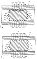
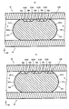
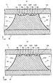
- FIG. 15 showing a sectional view of the vapor chamber 1 in the thickness direction along the y direction shown in C 7 -C 7 in FIG. Is a cross-sectional view taken along the vapor chamber 1 in the thickness direction along the x direction indicated by C 8 -C 8 1 in Figure 16.
- FIGS. 15 in the section corresponding to FIGS. 7 (a) at the portion indicated by C 9
- FIG. 18 (a) was expressed cross section corresponding to FIG. 13 (a) at the portion indicated by C 10
- the steam flow path 4 and the steam flow path 3 are separated by a convex portion 35a and a convex portion 39a, but FIG. And as described with reference to FIG. 14, the convex portion 35a and the convex portion 39a are provided with a communication opening 35b and a communication opening 39b, respectively. Therefore, according to the cross section in which the communication opening 35b and the communication opening 39b are in contact with the steam flow path 4 as shown in FIGS. 17 (b) and 18 (b), the steam flow path 4 and the steam flow path 3 are It communicates with the communication opening 35b and the communication opening 39b.
- the inner surface 10a of the first sheet 10 is overlapped on the first surface 30a side of the third sheet 30, and is placed on the second surface 30b side of the third sheet 30.
- the inner surface 20a of the second sheet 20 is arranged so as to be overlapped and joined to form the vapor chamber 1.
- the main body 31 of the third sheet 30 and the main body 11 of the first sheet 10 overlap, and the first sheet of the injection portion 32 of the third sheet 30 overlaps.
- the injection part 12 of 10 and the injection part 32 of the third sheet 30 and the injection part 22 of the second sheet 20 overlap each other.
- each configuration provided in the main body 11, the main body 21, and the main body 31 is shown in FIGS. 15, 16, 17 (a), and FIG. They are arranged as shown in 17 (b), FIG. 18 (a), and FIG. 18 (b). Specifically, it is as follows.
- the outer peripheral joint surface 33a provided on the first surface 30a side of the third sheet 30 and the outer peripheral surface of the inner surface 10a of the first sheet 10 are arranged so as to overlap with each other, and the second of the third sheet 30.
- the outer peripheral joining surface 33b provided on the surface 30b side and the outer peripheral surface of the inner surface 20a of the second sheet 20 are arranged so as to overlap each other, and are joined by a joining means such as diffusion joining or brazing.
- a hollow portion based on the shape of the third sheet 30 is formed between the first sheet 10 and the second sheet 20, and the working fluid is sealed therein to form a closed space 2.
- the inner surface 10a of the first sheet 10 is arranged so as to overlap the first surface 30a side of the outer peripheral liquid flow path portion 34 of the third sheet 30. As a result, the opening of the liquid flow path groove 35 is closed by the first sheet 10 and becomes a part of the hollow portion.
- the inner surface 20a of the second sheet 20 is arranged so as to overlap the second surface 30b side of the outer peripheral liquid flow path portion 34 of the third sheet 30. As a result, the opening of the liquid flow path groove 36 is closed by the second sheet 20 and becomes a part of the hollow portion.
- This is a condensate flow path 3 which is a second flow path through which the condensate in a state where the working fluid sealed in the hollow portion is condensed and liquefied flows.
- the inner surface 10a of the first sheet 10 is arranged so as to overlap the first surface 30a side of the inner liquid flow path portion 38 of the third sheet 30.
- the opening of the liquid flow path groove 39 is closed by the first sheet 10 and becomes a part of the hollow portion.
- This is a condensate flow path 3 which is a second flow path through which the condensate in a state where the working fluid sealed in the hollow portion is condensed and liquefied flows.
- the inner surface 20a of the second sheet 20 is arranged so as to overlap the second surface 30b side of the outer peripheral liquid flow path portion 38 of the third sheet 30.
- the opening of the liquid flow path groove 40 is closed by the second sheet 20 and becomes a part of the hollow portion.
- This is a condensate flow path 3 which is a second flow path through which the condensate in a state where the working fluid sealed in the hollow portion is condensed and liquefied flows.
- the condensate is moved by a strong capillary force, and smooth circulation is possible. That is, when considering a flow path assuming that the condensate flows, the condensate flow path 3 is compared with a flow path having a so-called groove in which one surface of the flow path is continuously open. According to this, high capillary force can be obtained. Further, since the condensate flow path 3 is formed separately from the vapor flow path 4 which is the first flow path, the circulation of the working fluid can be smoothed.
- the condensate flow path 3 by the liquid flow path groove 35 and the liquid flow path groove 39, and the condensate flow path 3 by the liquid flow path groove 36 and the liquid flow path groove 40 are provided, and the thickness direction of the vapor chamber 1 is provided.
- Condensate flow paths 3 are provided on one side and the other side (z direction), respectively.
- the total flow path cross-sectional area of the condensate flow path 3 can be made large while keeping the flow path cross-sectional area of one condensate flow path 3 small (thin), so that the capillary force can be maintained high.
- the flow of condensate can be smoothed.
- the shape of the condensate flow path 3 can be considered based on the shape and dimensions described in the third sheet 30 described above.
- the opening of the steam flow path groove 42 is closed by the first sheet 10 and the second sheet 20 to form a part of the hollow portion, which is the flow path of the enclosed working fluid.
- the steam flow path 4 is the first flow path through which steam flows.
- the surfaces of the first sheet 10 and the second sheet 20 that form a part of the steam flow path 4 on the steam flow path 4 side are flat.
- the surfaces of the first sheet 10 and the second sheet 20 are not processed and have a flat plate surface, so that the inner wall of the steam flow path 4 becomes smooth and the resistance when steam moves is suppressed. be able to.
- the flow path cross-sectional area of the condensate flow path 3 which is the second flow path is smaller than the flow path cross-sectional area of the vapor flow path 4 which is the first flow path. More specifically, the average flow path cross-sectional area of two adjacent steam flow paths 4 (in this embodiment, one steam flow path groove 42, a flow path surrounded by the first sheet 10, and the second sheet 20) is calculated.
- a l is 0.5 times the relation of a g It is preferably 0.25 times or less. This makes it easier for the working fluid to selectively pass between the first flow path and the second flow path depending on its phase mode (gas phase, liquid phase). This relationship may be satisfied in at least a part of the entire vapor chamber, and more preferably in the entire vapor chamber.
- the shape of the steam flow path 4 can be considered based on the shape and dimensions described in the third sheet 30 described above. Since the introduction section 37 and the introduction section 41 are provided in this embodiment, one steam flow path 4 is configured to be in contact with the two introduction sections.
- a plurality of steam flows are formed by closing the opening of the groove 44a of the steam flow path communication groove 44 of the third sheet 30 with the first sheet 10 and the opening of the groove 44b with the second sheet 20.
- a hollow portion through which the path 4 communicates is formed to serve as a flow path for the working fluid.
- the injection unit 12, the injection unit 22, and the injection unit 32 are also on the first surface 30a side of the injection unit 32 and on the second surface 30 side of the injection unit 32.
- the injection portions 22 overlap, the opening of the injection groove 32a on the second surface 30b side of the third sheet 30 is closed by the injection portion 22 of the second sheet 20, and the outside and the hollow portion (condensate flow path 3 and steam flow path 3).
- An injection flow path 5 communicating with 4) is formed.
- the injection flow path 5 is closed to form a closed space 2. Therefore, in the final form of the vapor chamber 1, the outside and the hollow portion are different. Not in communication.
- the injection unit 12, the injection unit 22, and the injection unit 32 are provided at one end of a pair of ends in the longitudinal direction of the vapor chamber 1. It is not limited, and may be arranged at any other end, or may be arranged in plurality. When a plurality are arranged, for example, they may be arranged at each of the pair of ends in the longitudinal direction of the vapor chamber 1, or may be arranged at one end of the other pair of ends.
- the working fluid is sealed in the closed space 2 of the vapor chamber 1.
- the type of the working fluid is not particularly limited, but a working fluid used in a normal vapor chamber such as pure water, ethanol, methanol, acetone, and a mixture thereof can be used.
- the vapor chamber as described above can be produced, for example, as follows. Liquid flow path groove 35, liquid flow path groove 36, liquid flow path groove 39, liquid flow path groove 40, vapor flow path groove 42, and groove 44a and groove 44b with respect to the sheet having the outer peripheral shape of the third sheet 30. Is formed by half etching. Half-etching is to perform etching halfway without penetrating in the thickness direction. However, the steam flow path groove 42 is half-etched from both the first surface 30a side and the second surface 30b side so as to penetrate in the thickness direction. By etching in this way, the shapes of the introduction portion 37 and the introduction portion 41 can be formed.
- the first sheet 10 is placed on the first surface 30a side of the third sheet 30, and the second sheet 20 is placed on the second surface 30b side of the third sheet 30 for temporary fixing.
- the method of temporary fixing is not particularly limited, and examples thereof include resistance welding, ultrasonic welding, and bonding with an adhesive.
- diffusion bonding is performed to permanently join the first sheet 10, the second sheet 20, and the third sheet 30 to form a vapor chamber sheet.
- "permanently joined” is not bound by a strict meaning, and is joined to the extent that the sealing of the sealed space 2 can be maintained during the operation of the vapor chamber 1. Means to be.
- the internal liquid flow path portion 38 functions as a support column, it is possible to prevent the closed space from being crushed during joining and depressurization.
- the manufacturing method is not limited to this, and the vapor chamber can also be manufactured by pressing, cutting, laser processing, and processing with a 3D printer.
- the vapor chamber can also be manufactured by pressing, cutting, laser processing, and processing with a 3D printer.
- a vapor chamber is manufactured by a 3D printer, it is not necessary to join a plurality of sheets to make the vapor chamber, and it is possible to form a vapor chamber without a joint.
- FIG. 19 schematically shows a state in which the vapor chamber 1 is arranged inside the portable terminal 80, which is a form of an electronic device.
- the vapor chamber 1 is arranged inside the housing 81 of the portable terminal 80, it is represented by a dotted line.
- Such a portable terminal 80 is configured to include a housing 81 containing various electronic components and a display unit 82 exposed so that an image can be seen to the outside through an opening of the housing 81.
- an electronic component 53 to be cooled by the vapor chamber 1 is arranged in the housing 51.
- the vapor chamber 1 is installed in a housing of a portable terminal or the like, and is attached to an electronic component 83 which is an object to be cooled such as a CPU.
- the electronic components are attached directly to the outer surface or outer surface of the vapor chamber 1 or via an adhesive, sheet, tape or the like having high thermal conductivity.
- the position of the electronic component 83 to be attached to the vapor chamber is not particularly limited, and is appropriately set depending on the arrangement of other members in a portable terminal or the like.
- the electronic component 53 is arranged at the center of the main body 21 in the xy direction on the surface of the second sheet 20 opposite to the side on which the third sheet 30 is arranged. Therefore, in FIG.
- FIG. 20 shows a diagram illustrating the flow of the working fluid.
- the first surface 30a side of the third sheet 30 is displayed so as to be visible inside the vapor chamber 1.
- the heat is transferred through the second sheet 20 by heat conduction, and the condensate existing in the closed space 2 near the electronic component 83 receives heat.
- the condensate that receives this heat absorbs the heat and evaporates and vaporizes. As a result, the electronic component 83 is cooled.
- the vaporized working fluid becomes steam and moves in the steam flow path 4 as shown by the straight line arrow in FIG. 20. Since this flow is generated in the direction away from the electronic component 83, the steam moves in the direction away from the electronic component 83.
- the steam in the steam flow path 4 separates from the electronic component 83, which is a heat source, and moves to the outer peripheral portion of the vapor chamber 1, which has a relatively low temperature.
- the three sheets 30 are cooled while being deprived of heat.
- the first sheet 10, the second sheet 20, and the third sheet 30, which have taken heat from the steam, transfer the heat to the housing 81 of the electronic device 80 in contact with the vapor chamber, and finally the heat is released to the outside air.
- the condensate flow path 3 of the present embodiment includes a communication opening 35b, a communication opening 36b, a communication opening 39b, and a communication opening 40b, so that the condensate liquid is provided. Is distributed to a plurality of condensate flow paths 3 through these communication openings.
- the condensate flow path 3 is provided in both the thickness directions of the vapor chamber 1, it is possible to increase the chances of movement from the vapor flow path 4 to the condensate flow path 3, which is smoother.
- the condensate can be moved.
- the introduction portion 37 and the introduction portion 41 are provided, a portion surrounded by the introduction surface 37b, the introduction surface 41b, the first sheet 10, and the second sheet 20 is formed, and the action of capillary force is generated. This makes it easier for the condensate to collect here. As a result, the condensed liquid is introduced into the condensed liquid flow path 3 more smoothly.
- the condensate that has entered the condensate flow path 3 approaches the electronic component 83 that is the heat source as shown by the dotted straight arrow in FIG. 20 due to the capillary force of the condensate flow path and the pressure from the vapor. Moving. Then, it is vaporized again by the heat from the electronic component 83 which is a heat source, and the above is repeated.
- the condensate flow path 3 is provided on both one side and the other side in the thickness direction (z direction) of the vapor chamber 1. As a result, the total flow path cross-sectional area of the condensate flow path 3 can be made large while keeping the flow path cross-sectional area of one condensate flow path 3 small (thin), so that the capillary force can be maintained high.
- the flow of condensate can be smoothed.
- the vapor chamber 1 up to this point is composed of three sheets, a first sheet 10, a second sheet 20, and a third sheet 30, has been described.
- the vapor chamber 1 up to this point is composed of three sheets in this way, it is easier to manufacture because there is no complexity in stacking the sheets as compared with the case where more sheets are used, and the bonding of each sheet is made stronger. be able to.
- the surfaces of the first sheet 10 and the second sheet 20 are not processed and have a flat shape as in the present embodiment, the condensate flow path and the vapor flow path are formed when the sheets are overlapped. Since it is not necessary to worry about the alignment for forming, simpler manufacturing becomes possible.
- the condensate flow path may be provided on one side and the other side in the thickness direction of the vapor chamber, and the number of sheets may be four or five.
- the vapor chamber By forming the vapor chamber with three or more sheets in this way, it becomes easier to form the introduction surface 41b as shown in FIG. 18 as compared with the case where the vapor chamber is composed of two sheets, and the working fluid is condensed here. It becomes easier to move the working fluid more smoothly.
- a groove is also formed in the center of the inner liquid flow path portion 38 in the thickness direction. It can also be formed to provide a condensate flow path.
- FIG. 22 is an exploded perspective view of the vapor chamber 51, which corresponds to FIG.
- FIG. 23 is a view showing the closed space 2 of the vapor chamber 51 so as to be visible, and is a view showing the first surface 30a side of the third sheet 52 so as to be visible.
- Figure 24 represents a cross-sectional view of the vapor chamber 101 at a position indicated by C 12 -C 12 in FIG.
- Figure 25 is a view corresponding to Figure 18 a view showing an enlarged vicinity of a portion indicated by C 13 of FIG. 24 (inner liquid flow path 138).
- a third sheet 52 is applied to the vapor chamber 1 described above instead of the third sheet 30, and the third sheet 52 communicates with the inner liquid flow path portion 54 of the main body 53 in the thickness direction.
- the difference is that the hole 54a is provided. Since the description of the vapor chamber 1 is valid for other members and parts, the same reference numerals are given to the drawings and the description thereof will be omitted. Therefore, here, the description will be focused on the thickness direction communication hole 54a provided in the inner liquid flow path portion 54.
- the thickness direction communication hole 54a is a hole provided in the inner liquid flow path portion 54 of the third sheet 52 and communicating from the first surface 30a to the second surface 30b.
- the liquid flow path groove 39 and the liquid flow path groove 40 are communicated with each other by the thickness direction communication hole 54a, and the condensate flow path 3 on the first surface 30a side and the condensate flow path 3 on the second surface 30b side are communicated with each other.
- communication without the condensate flow path 3 separately disposed in the thickness direction through the steam flow path 4 to further equalize the distribution of the condensate Therefore, the working fluid can flow more smoothly.
- the thickness direction communication hole 54a need only be able to communicate the condensate flow path 3 arranged on one side and the other side of one inner liquid flow path portion 54 in the thickness direction, and the specific form for that purpose is particularly limited. Will not be done. For example, it can be explained as follows.
- the cross-sectional shape of the thickness direction communication hole 54a shown in FIGS. 22 and 23 is not particularly limited, and is a circle, an ellipse, a triangle, a quadrangle, another polygon, and a geometry obtained by combining these. It can be a geometric shape.
- the shape in the direction in which the thickness direction communication hole 54a extends is not particularly limited, and the cross-sectional shape may be constant at each position in the z direction. , May change.
- the cross-sectional area is greatly expanded with respect to the other portion can be mentioned.
- the number of condensate flow paths 3 connected by one thickness direction communication hole 54a is not particularly limited. As in this embodiment, the two condensate flow paths 3 on the first surface 30a side and the two condensate flow paths 3 on the second surface 30b side may be configured to communicate with each other, or one of them in the thickness direction. One or three or more condensate flow paths 3 may be configured to communicate with each other on the surface side.
- At least one thickness direction communication hole 54a is provided in the vapor chamber 1, the effect is exhibited, but for a more remarkable effect, it is preferable to provide a plurality of thickness direction communication holes 54a.
- the mode in which the plurality of thickness direction communication holes 54a are provided is not particularly limited, but one may be provided in one inner liquid flow path portion 54, and a plurality of thickness directions may be provided in one inner liquid flow path portion 54.
- the communication hole 54a may be provided.
- a plurality of thickness direction communication holes 54a are arranged in one inner liquid flow path portion 54, they may be arranged in a straight line, and as shown in FIG. 23, adjacent thickness direction communication holes 54a may be arranged. Then, the position in the direction orthogonal to the line-up direction (y direction) may be shifted.
- the thickness direction communication hole 54a is provided only in the inner liquid flow path portion 54, but instead, the thickness direction communication hole may be provided only in the outer peripheral liquid flow path portion 34, or the inner liquid may be provided. Thickness direction communication holes may be provided in both the flow path portion 54 and the outer peripheral liquid flow path portion 34.
- FIG. 26 shows an external perspective view of the vapor chamber 101 according to the form 2a
- FIG. 27 shows an exploded perspective view of the vapor chamber 101.
- the vapor chamber 101 of the present embodiment has a first sheet 10, a second sheet 20, and a third sheet 130 (sometimes referred to as “intermediate sheet 130”). ing. Then, as will be described later, these sheets are overlapped and joined (diffusion joining, brazing, etc.) so that the shape of the third sheet 130 is formed between the first sheet 10 and the second sheet 20. It becomes a sheet for a vapor chamber in which a hollow portion based on the base is formed. Then, the working fluid is sealed in the hollow portion to form a closed space 102 (see, for example, FIG. 19), which becomes a vapor chamber 101.
- first sheet 10 and the second sheet 20 provided in this embodiment can be considered in the same manner as the first sheet 10 and the second sheet 20 described in the first form, the reference numerals are the same here, and the description thereof will be made. Is omitted.
- the third sheet 130 is a sheet sandwiched and stacked between the inner surface 10a of the first sheet 10 and the inner surface 20a of the second sheet 20, and has a structure for the closed space 2 in which the working fluid moves. It is equipped. 28 and 29 are views (viewed from the z direction) of the third sheet 130 in a plan view.
- FIG. 28 is a view of the surface stacked on the first sheet 10
- FIG. 29 is a view of the surface stacked on the second sheet 20.
- FIG. 30 shows a cross-sectional view taken along the line shown by C 101- C 101 in FIG. 28, and
- FIG. 31 shows a cross-sectional view taken along the line shown by C 102- C 102 in FIG. 28.
- the third sheet 130 may also be a single layer, or a plurality of sheets may be laminated.
- the plurality of sheets may be laminated and then formed into the following form, or the plurality of sheets may be individually processed and then overlapped to form the following form. You may.
- the third sheet 130 includes a first surface 130a that overlaps the inner surface 10a of the first sheet 10, a second surface 130b that overlaps the inner surface 20a of the second sheet 20, and the first surface 130a and the second surface 130b. It includes an end face 130c that is passed to form a thickness. Therefore, the first surface 130a appears in FIG. 28, and the second surface 130b appears in FIG. 29.
- the third sheet 130 includes a main body 131 and an injection unit 32. Since the injection unit 32 of the present embodiment can be considered in the same manner as the injection unit 32 shown in the first aspect, the same reference numerals are given here and the description thereof will be omitted.
- the main body 31 is a hollow portion in the sheet for the vapor chamber and a sheet-like portion forming a closed space in the vapor chamber 1, and in this embodiment, the main body 31 is a rectangle having an arc (so-called R) at an angle in a plan view. However, the main body 31 has a quadrangular shape as in this embodiment, and can also have a shape required as a vapor chamber.
- it may be a circle, an ellipse, a triangle, another polygon, and a shape having a bent portion, for example, an L-shape, a T-shape, a crank-type U-shape, or the like.
- the shape may be a combination of at least two of these.
- the thickness and material of the third sheet 130 can be considered in the same manner as the first sheet 10. However, the thickness and material of the third sheet 130 do not have to be the same as those of the first sheet 10, and may be configured differently.
- the main body 131 is formed with a structure for refluxing the working fluid. Specifically, the main body 131 is provided with an outer peripheral joint portion 33, an outer peripheral liquid flow path portion 134, an inner liquid flow path portion 138, a vapor flow path groove 142, and a vapor flow path communication groove 144. There is.
- the vapor chamber 101 of this embodiment is the first flow path through which the vapor of the working fluid passes through the steam flow path 4 (see FIG. 38, etc.) and the second flow path through which the working fluid is condensed and liquefied.
- a condensate flow path 3 (see FIG. 42 and the like) is provided.
- the vapor flow path groove 142 of the third sheet 130 forms the vapor flow path 4, and the liquid flow path 35 provided in the outer peripheral liquid flow path portion 134 and the liquid flow provided in the inner liquid flow path portion 138.
- the path groove 39 forms the condensate flow path 3.
- outer peripheral joint portion 33 can be considered in the same manner as the outer peripheral joint portion 33 described in the above-described first embodiment, the same reference numerals are given here and the description thereof will be omitted.
- the outer peripheral liquid flow path portion 134 functions as a liquid flow path portion, constitutes a part of a condensate flow path 3 which is a second flow path through which the working fluid is condensed and liquefied, and also forms a heat insulating portion 6. It includes a constituent part.
- FIG. 32 the portion indicated by the arrow C 103 in FIG. 30 is enlarged and shown.
- FIG. 33 shows an enlarged view of the outer peripheral liquid flow path portion 134 viewed from the direction indicated by the arrow C 105 in FIG. 32 as viewed from the z direction. That is, FIG. 33 shows a part of the outer peripheral liquid flow path portion 134 as seen from the second surface 130b.
- the outer peripheral liquid flow path portion 134 is a portion of the main body 131 formed along the inside of the outer peripheral joint portion 33 and provided along the outer circumference of the portion that becomes the closed space 2.
- Liquid flow path grooves 35 which are a plurality of grooves extending parallel to the outer peripheral direction of the main body 131, are formed on the first surface 130a of the outer peripheral liquid flow path portion 134, and the plurality of liquid flow path grooves 35 extend in the extending direction. They are arranged in different directions at predetermined intervals. Since the liquid flow path groove 35 can be considered in the same manner as the liquid flow path groove 35 described in the above-described first embodiment, the same reference numerals are given here and the description thereof will be omitted.
- the outer peripheral liquid flow path portion 134 is provided with the heat insulating portion groove 136 on the second surface 30b side.
- the heat insulating groove 136 is a groove extending along the direction in which the outer peripheral liquid flow path 134 extends, does not communicate with the vapor flow path groove 42 or the liquid flow path groove 35, and operates in the heat insulating groove 136. It is configured to prevent fluid from flowing in.
- the heat insulating portion groove 136 is a groove, it has a bottom portion in its cross-sectional shape, and the opposite side (second surface 130b) facing the bottom portion is open. As will be described later, when the second sheet 20 is overlapped with the third sheet 30, this opening is closed to form the heat insulating portion 6.
- the heat insulating groove 136 has a semi-elliptical cross section.
- the cross-sectional shape is not limited to a semi-elliptical shape, and may be a quadrangle such as a circle, a rectangle, a square, a trapezoid, another polygon, or a shape obtained by combining any one or more of these. ..
- FIG. 34 shows a cross-sectional view of C 106- C 106 shown in FIG. 33. That is, FIG. 34 is a cross-sectional view of the outer peripheral liquid flow path portion 134 at the portion provided with the pillar 136a.
- the cross section shown in FIG. 32 is a cross-sectional view of the outer peripheral liquid flow path portion 134 in the portion of the heat insulating portion groove 136 where the pillar 136a is not arranged.
- a plurality of columns 136a erected from the bottom are arranged at intervals.
- the plan view shape of the pillar is not particularly limited, and is not particularly limited as in this form, but also a polygon such as a triangle or a pentagon, a circle, an ellipse, or an arbitrary shape. Can be applied.
- the pitch and number of pillars to be arranged are not particularly limited and can be set as appropriate. Therefore, the number of columns may be reduced to 1 or less, and one column may be long so as to extend along the groove for the heat insulating portion.
- an introduction portion 37 is provided in the outer peripheral liquid flow path portion 134. Since the introduction unit 37 can be considered in the same manner as the introduction unit 37 described in the first embodiment, the same reference numerals are given and the description thereof will be omitted here.
- the outer peripheral liquid flow path portion 134 having the above configuration may further have the following configuration.
- the width of the outer peripheral liquid flow path portion 134 (the size in the direction in which the liquid flow path grooves 35 are arranged) shown by W 102 in FIGS. 28 to 30 and 32 is appropriately set from the size of the entire vapor chamber and the like.
- the width W 102 is preferably 3.0 mm or less, and may be 1.5 mm or less, or 1.0 mm or less. If the width W 102 exceeds 3.0 mm, there is a risk that sufficient space for the inner liquid flow path and vapor flow path cannot be secured.
- the width W 102 is preferably 0.05 mm or more, and may be 0.1 mm or more, or 0.2 mm or more.
- the range of the width W 102 may be determined by a combination of any one of the plurality of upper limit candidate values and one of the plurality of lower limit candidate values. Further, the range of the width W 102 may be defined by any combination of a plurality of upper limit candidate values or any combination of a plurality of lower limit candidate values.
- the width of the outer peripheral liquid flow path portion 134 on the first surface 130a side and the width of the second surface 130b side are both shown by W 102 , but the width of the outer peripheral joining surface 33a and the width of the outer peripheral joining surface 33b are shown. It does not have to be the same, but may have different widths.
- the groove width shown by W 104 in FIG. 32 is preferably 1500 ⁇ m or less, and may be 1000 ⁇ m or less, or 700 ⁇ m or less.
- the width W 104 is preferably 20 ⁇ m or more, and may be 45 ⁇ m or more, or 60 ⁇ m or more.
- the range of the width W 104 may be defined by a combination of any one of the plurality of upper limit candidate values and one of the plurality of lower limit candidate values. Further, the range of the width W 104 may be defined by any combination of a plurality of upper limit candidate values or by any combination of a plurality of lower limit candidate values. Further, the depth of the groove shown by D 102 in FIG.
- the depth D 102 is preferably 200 ⁇ m or less, and may be 150 ⁇ m or less, or 100 ⁇ m or less.
- the depth D 102 is preferably 5 ⁇ m or more, and may be 10 ⁇ m or more, or 20 ⁇ m or more.
- the range of the depth D 102 may be defined by a combination of any one of the plurality of upper limit candidate values and one of the plurality of lower limit candidate values. Further, the range of the depth D 102 may be defined by any combination of a plurality of upper limit candidate values or by any combination of a plurality of lower limit candidate values.
- the inner liquid flow path portion 138 is also a part of the condensate flow path 3 which is a second flow path through which the working fluid is condensed and liquefied, a part which constitutes the heat insulating portion 6, and a portion which constitutes the introduction portion 41.
- FIG. 35 the portion indicated by the arrow C 107 in FIG. 30 is enlarged and shown.
- FIG. 35 also shows the cross-sectional shapes of the inner liquid flow path portion 38, the heat insulating groove 140, and the introduction portion 41.
- FIG. 36 shows an enlarged view of the inner liquid flow path portion 138 viewed from the direction indicated by the arrow C 109 in FIG. 35 in a plan view.
- the inner liquid flow path portion 138 is a portion of the main body 131 formed inside the annular ring of the outer liquid flow path portion 134.
- the inner liquid flow path portion 138 of the present embodiment extends in a direction (x direction) parallel to the long side of the rectangle in the plan view (when viewed from the z direction) of the main body 131, and a plurality of (three in this embodiment) inner liquids.
- the flow path portions 138 are arranged at predetermined intervals in a direction parallel to the short side (y direction).
- Liquid flow path grooves 39 which are a plurality of grooves extending in the direction in which the inner liquid flow path portion 138 extends, are formed on the first surface 130a of the inner liquid flow path portion 138, and the plurality of liquid flow path grooves 39 are formed. They are arranged at predetermined intervals in a direction different from the extending direction.
- the liquid flow path groove 39 can be considered in the same manner as the liquid flow path groove 39 described in the first embodiment, the same reference numerals are given and the description thereof will be omitted.
- the inner liquid flow path portion 138 is provided with a groove 140 for a heat insulating portion on the second surface 130b.
- the heat insulating groove 140 is a groove extending along the direction in which the inner liquid flow path 138 extends, does not communicate with the vapor flow path groove 42 or the liquid flow path groove 39, and operates in the heat insulating groove 140. It is configured to prevent fluid from flowing in.
- the heat insulating portion groove 140 is a groove, it has a bottom portion in its cross-sectional shape, and the opposite side (second surface 130b) facing the bottom portion is open. As will be described later, when the second sheet 20 is overlapped with the third sheet 30, this opening is closed to form the heat insulating portion 6.
- the heat insulating groove 140 has a semi-elliptical cross section.
- the cross-sectional shape is not limited to a semi-elliptical shape, and may be a quadrangle such as a circle, a rectangle, a square, a trapezoid, another polygon, or a shape obtained by combining any one or more of these. ..
- FIG. 37 shows a cross-sectional view taken along the line C 110- C 110 shown in FIG. 36. That is, FIG. 37 is a cross-sectional view of the inner liquid flow path portion 138 at the portion provided with the pillar 140a.
- the cross-sectional view shown in FIG. 35 is a cross-sectional view of the inner liquid flow path portion 138 in the portion of the groove 140 for the heat insulating portion where the pillar 140a is not arranged.
- a plurality of pillars 140a erected from the bottom are arranged at intervals in the groove of the heat insulating portion groove 140.
- the plan view shape of the pillar is not particularly limited, and is not particularly limited as in this form, but also a polygon such as a triangle or a pentagon, a circle, an ellipse, or an arbitrary shape. Can be applied.
- the pitch and number of pillars to be arranged are not particularly limited and can be set as appropriate. Therefore, the number of columns may be reduced to one or less, and one column may be long so as to extend along the heat insulating groove.
- the introduction portion 41 is provided in the inner liquid flow path portion 138. Since the introduction unit 41 can be considered in the same manner as the introduction unit 41 described in the first embodiment, the same reference numerals are given and the description thereof will be omitted.
- the inner liquid flow path portion 138 having the above structure is preferably further provided with the following structure.
- the width of the inner liquid flow path portion 138 shown by W 106 in FIGS. 28 to 30 and 35 (the largest value in the direction in which the inner liquid flow path portion 138 and the steam flow path groove 42 are arranged) is It is preferably 3000 ⁇ m or less, and may be 2000 ⁇ m or less, or 1500 ⁇ m or less.
- the width W 106 is preferably 100 ⁇ m or more, and may be 200 ⁇ m or more, or 400 ⁇ m or more.
- the range of the width W 106 may be determined by a combination of any one of the plurality of upper limit candidate values and one of the plurality of lower limit candidate values. Further, the range of the width W 106 may be defined by any combination of a plurality of upper limit candidate values or any combination of a plurality of lower limit candidate values.
- the pitch of the plurality of inner liquid flow path portion 138 shown in P 102 in Figure 30 may be that it is less preferable 3500 ⁇ m or less 5000 .mu.m, may be not more than 3000 .mu.m.
- the pitch P 102 is preferably 200 ⁇ m or more, and may be 400 ⁇ m or more, or 800 ⁇ m or more.
- the range of the pitch P 102 may be determined by a combination of any one of the plurality of upper limit candidate values and one of the plurality of lower limit candidate values. Further, the range of the pitch P 102 may be defined by any combination of a plurality of upper limit candidate values or any combination of a plurality of lower limit candidate values.
- the inner liquid flow path portion 38 having the above configuration may further have the following configuration.
- the groove width shown by W 108 in FIG. 35 is preferably 1500 ⁇ m or less, and may be 1000 ⁇ m or less, or 700 ⁇ m or less.
- the width W 108 is preferably 20 ⁇ m or more, and may be 45 ⁇ m or more, or 60 ⁇ m or more.
- the range of the width W 108 may be defined by a combination of any one of the plurality of upper limit candidate values and one of the plurality of lower limit candidate values. Further, the range of the width W 108 may be defined by any combination of a plurality of upper limit candidate values or by any combination of a plurality of lower limit candidate values. Further, the depth of the groove shown by D 104 in FIG.
- the depth D 104 is preferably 5 ⁇ m or more, and may be 10 ⁇ m or more, or 20 ⁇ m or more.
- the range of the depth D 104 may be defined by a combination of any one of the plurality of upper limit candidate values and one of the plurality of lower limit candidate values. Further, the range of the depth D 104 may be defined by any combination of a plurality of upper limit candidate values or any combination of a plurality of lower limit candidate values.
- the steam flow path groove 142 is a portion through which the vaporized steam by evaporating the working fluid passes, and constitutes a part of the steam flow path 4 (see FIG. 19 and the like) which is the first flow path.
- 28 and 29 show the shape of the steam flow path groove 142 in a plan view
- FIG. 30 shows the cross-sectional shape of the steam flow path groove 142.
- the vapor flow path groove 142 is formed of a groove (slit) formed inside the annular ring of the outer peripheral liquid flow path portion 134 in the main body 131.
- the steam flow path groove 142 of the present embodiment is formed between the adjacent inner liquid flow path portions 138 and between the outer peripheral liquid flow path portion 134 and the inner liquid flow path portion 138, and is viewed in a plan view of the main body 131. It is a rectangular groove extending in the direction parallel to the long side (x direction). A plurality of (four in this embodiment) steam flow path grooves 142 are arranged in a direction parallel to the short side (y direction).
- the steam flow path groove 142 of the present embodiment is configured to communicate the first surface 130a and the second surface 130b side of the third sheet 130, that is, it is a slit-shaped groove, and the first surface 130a and the second surface 130a and the second surface 130a. It is open to the surface 130b side. Therefore, as can be seen from FIG. 30, the third sheet 130 has a shape in which the outer peripheral liquid flow path portion 134, the inner liquid flow path portion 138, and the vapor flow path groove 142 are alternately repeated in the y direction.
- the configuration of the steam flow path groove 142 having such a configuration can be considered in the same manner as the steam flow path groove 42 described in the first embodiment.
- the steam flow path communication groove 44 is a groove that communicates a plurality of steam flow path grooves 142, and can be considered in the same manner as the steam flow path communication groove 44 described in the above-described first embodiment, and is therefore described with the same reference numerals. Is omitted.
- FIG. 38 shows a cross-sectional view of the vapor chamber 101 cut in the thickness direction along the y direction shown by C 111- C 111 in FIG.
- FIG. 39 shows a cross-sectional view of the vapor chamber 101 cut in the thickness direction along the x direction shown by C 112 to C 112 in FIG. 40 shows the portion shown by C 113 in FIG. 38
- FIG. 41 shows the portion of the outer peripheral liquid flow path portion 134 provided with the pillar 136a
- FIG. 42 shows the portion shown by C 114 in FIG. 38
- FIG. 43 shows. Is an enlarged representation of the portion of the inner liquid flow path portion 138 provided with the pillar 140a.
- the vapor flow path 4 and the condensate flow path 3 are separated by a convex portion 35a and a convex portion 39a, but the convex portion 35a and the convex portion 39a are each separated by a communication opening 35b. And a communication opening 39b is provided. Therefore, the vapor flow path 4 and the condensate flow path 3 are communicated with each other by the communication opening 35b and the communication opening 39b.
- the inner surface 10a of the first sheet 10 is overlapped on the first surface 130a side of the third sheet 130, and is placed on the second surface 130b side of the third sheet 130.
- the inner surface 20a of the second sheet 20 is arranged so as to be overlapped and joined to form a vapor chamber 101.
- the main body 131 of the third sheet 130 and the main body 11 of the first sheet 10 overlap, and the first sheet of the injection portion 32 of the third sheet 130 overlaps.
- the injection part 12 of 10 and the injection part 32 of the third sheet 130 and the injection part 22 of the second sheet 20 overlap each other.
- the configurations provided in the main body 11, the main body 21, and the main body 131 are arranged so as to appear in FIGS. 38 to 42. Specifically, it is as follows.
- the outer peripheral joint surface 33a provided on the first surface 130a side of the third sheet 130 and the outer peripheral surface of the inner surface 10a of the first sheet 10 are arranged so as to overlap with each other, and the second surface of the third sheet 30.
- the outer peripheral joining surface 33b provided on the 30b side and the outer peripheral surface of the inner surface 20a of the second sheet 20 are arranged so as to overlap each other, and are joined by a joining means such as diffusion joining or brazing.
- a hollow portion based on the shape of the third sheet 130 is formed between the first sheet 10 and the second sheet 20, and the working fluid is sealed therein to form a closed space 102.
- the inner surface 10a of the first sheet 10 is arranged so as to overlap the first surface 130a side of the outer peripheral liquid flow path portion 134 of the third sheet 130. As a result, the opening of the liquid flow path groove 35 is closed by the first sheet 10 and becomes a part of the hollow portion.
- This is a condensate flow path 3 which is a second flow path through which the condensate in a state where the working fluid sealed in the hollow portion is condensed and liquefied flows.
- the inner surface 20a of the second sheet 20 is arranged so as to overlap the second surface 30b side of the outer peripheral liquid flow path portion 134 of the third sheet 130. As a result, the opening of the heat insulating portion groove 136 is closed by the second sheet 20 to become the heat insulating portion 6.
- the heat insulating portion 6 is configured so as not to communicate with the condensate flow path 3 and the vapor flow path 4, and the thermal conductivity thereof is lower than that of the material adjacent to the heat insulating portion 6.
- the heat insulating portion 6 is not particularly limited, but the heat insulating portion 6 may be evacuated, filled with air or other gas, or filled with a material having low thermal conductivity.
- the inner surface 10a of the first sheet 10 is arranged so as to overlap the first surface 130a side of the inner liquid flow path portion 138 of the third sheet 130. As a result, the opening of the liquid flow path groove 39 is closed by the first sheet 10 and becomes a part of the hollow portion.
- This is a condensate flow path 3 which is a second flow path through which the condensate in a state where the working fluid sealed in the hollow portion is condensed and liquefied flows.
- the inner surface 20a of the second sheet 20 is arranged so as to overlap the second surface 130b side of the inner liquid flow path portion 138 of the third sheet 130. As a result, the opening of the heat insulating portion groove 140 is closed by the second sheet 20 to become the heat insulating portion 6.
- the heat insulating portion 6 is configured so as not to communicate with the condensate flow path 3 and the vapor flow path 4, and has a thermal conductivity lower than that of the material adjacent to the heat insulating portion 6.
- the heat insulating portion 6 is not particularly limited, but the heat insulating portion 6 may be evacuated, filled with air or other gas, or filled with a material having low thermal conductivity.
- the condensate flow path 3 by forming a narrow flow path surrounded by walls on all four sides in the cross section, the condensate is moved by a strong capillary force, and smooth circulation is possible. That is, when considering a flow path assuming that the condensate flows, the condensate flow path 3 is compared with a flow path having a so-called groove in which one surface of the flow path is continuously open. According to this, high capillary force can be obtained. Further, since the condensate flow path 3 is formed separately from the vapor flow path 4 which is the first flow path, the circulation of the working fluid can be smoothed.
- a heat insulating portion having a reduced thermal conductivity is provided on the opposite side of the condensate flow path 3 in the thickness direction (z direction) of the vapor chamber 101.
- the heat transfer to the working fluid is slowed down, and the local temperature rise and the local temperature drop are alleviated, so that the uniformity can be improved. More specifically, it is possible to suppress the obstruction of the flow of the working fluid due to dryout due to rapid heating or clogging of the condensate due to condensation earlier than necessary, and it is possible to enhance the heat transport capacity.
- the shape of the condensate flow path 3 and the heat insulating portion 6 can be considered based on the shape and dimensions described in the third sheet 130 described above.
- the opening of the steam flow path groove 142 is closed by the first sheet 10 and the second sheet 20 to form a part of the hollow portion, which forms the flow path of the working fluid. It becomes the steam flow path 4 which is the first flow path through which steam flows.
- the relationship between the flow path cross-sectional area of the condensate flow path 3 and the flow path cross-sectional area of the vapor flow path 4 is the flow path cross-sectional area of the condensate flow path 3 and the flow path cross-sectional area of the vapor flow path 4 described in the first embodiment. Can be thought of in the same way as the relationship of.
- the shape of the steam flow path 4 can be considered based on the shape and dimensions described in the third sheet 130 described above. Since the introduction section 37 and the introduction section 41 are provided in this embodiment, the steam flow path 4 is configured to be in contact with the two introduction sections.
- the opening of the groove 44a of the steam flow path communication groove 44 of the third sheet 130 is closed by the first sheet 10, and the opening of the groove 44b is closed by the second sheet 20, so that a plurality of steam flows are formed.
- a hollow portion through which the path 4 communicates is formed to serve as a flow path for the working fluid.
- the working fluid is sealed in the closed space 102 of the vapor chamber 101.
- the type of the working fluid is not particularly limited, but a working fluid used in a normal vapor chamber such as pure water, ethanol, methanol, acetone, and a mixture thereof can be used.
- the vapor chamber as described above can be produced, for example, as follows. With respect to the sheet having the outer peripheral shape of the third sheet 130, the liquid flow path groove 35, the heat insulating portion groove 136, the liquid flow path groove 39, the heat insulating portion groove 140, the vapor flow path groove 142, and the groove 44a and the groove 44b. Is formed by half etching. However, the steam flow path groove 142 is half-etched from both the first surface 130a side and the second surface 130b side so as to penetrate in the thickness direction. By etching in this way, the shapes of the introduction portion 37 and the introduction portion 41 can also be formed.
- the first sheet 10 is placed on the first surface 130a side of the third sheet 130, and the second sheet 20 is placed on the second surface 130b side of the third sheet 130 for temporary fixing.
- the method of temporary fixing is not particularly limited, and examples thereof include resistance welding, ultrasonic welding, and bonding with an adhesive.
- diffusion bonding is performed to permanently join the first sheet 10, the second sheet 20, and the third sheet 130 to form a vapor chamber sheet.
- "permanently joined” is not bound by a strict meaning, and is joined to such an extent that the hermeticity of the sealed space 102 can be maintained during the operation of the vapor chamber 101. Means to be.
- the heat insulating portion 6 By performing this joining in a vacuum, the heat insulating portion 6 can be evacuated, and when performed in the air or other gas, the heat insulating portion 6 can be filled with a gas corresponding thereto. If the heat insulating groove 136 is provided with a pillar 136a and the heat insulating groove 140 is provided with a pillar 140a, it is necessary to provide the pillars at the time of joining, at the time of decompression of the hollow portion described below, and at the time of injecting the working fluid. It is possible to suppress the crushing and swelling of the heat insulating portion 6. Further, when a solid material is put in the heat insulating portion 6, the material may be put in the groove for the heat insulating portion before joining.
- the internal liquid flow path portion 138 functions as a support column, it is possible to prevent the closed space from being crushed during joining and depressurization.
- the heat insulating portion 6 is provided on the opposite side of the condensate flow path 3 in the thickness direction (z direction) of the vapor chamber 101, the heat transfer to the working fluid becomes gentle and is localized. Since the temperature rise and the local temperature drop are reduced, the uniformity can be improved. That is, it is possible to suppress obstruction of the flow of the working fluid due to dryout due to rapid heating or clogging of the condensate due to condensation earlier than necessary, and it is possible to enhance the heat transport capacity. Therefore, the heat insulating portion is not necessarily arranged in the entire vapor chamber, and may be arranged only in a portion where local heat transfer is expected. Examples thereof include a portion where a heat source (electronic component) is arranged, and conversely, an end portion of a vapor chamber separated from the heat source.
- a heat source electronic component
- the introduction portion 37 and the introduction portion 41 are provided, a portion surrounded by the introduction surface 37b and the introduction surface 41b and the first sheet 10 and the second sheet 20 is formed, and the action of the capillary force causes the introduction portion 37 and the introduction portion 41 to be provided. Condensate tends to collect here. As a result, the condensed liquid is introduced into the condensed liquid flow path 3 more smoothly.
- FIG. 44 shows an example in which the groove 140 for the heat insulating portion is provided on a part of the second surface 130b of the third sheet 130. This figure corresponds to FIG. 29.
- the heat insulating portion 6 is also limited to the portion where the groove 140 for the heat insulating portion is provided. This is for thermal design, for example, a heat insulating portion 6 is provided in a portion close to the cooling target and a portion where condensation is desired to be suppressed, and a heat insulating portion 6 is not provided in a portion where condensation is desired to be performed promptly.
- a heat insulating portion can be provided.
- FIG. 45 to 47 are examples in which the heat insulating portion 6 is also provided in the steam flow path 4. Both are diagrams corresponding to FIG. 38.
- FIG. 45 shows an example in which the heat insulating portion 6 is provided in each of the condensate flow path 3 and the vapor flow path 4.
- FIG. 46 shows an example in which the heat insulating portion 6 communicates through the condensate flow path 3 and the vapor flow path 4.
- FIG. 47 is an example in which the heat insulating portion 6 is provided only in the steam flow path 4.
- the introduction unit 37 and the introduction unit 39 have been described in the first and second forms, the introduction unit will be described in detail in the third form. Therefore, the configurations other than the introduction portion can be considered in the same manner as in the above-described first and second forms, and the description thereof will be omitted.
- the second surface 30b of the third sheet 30 is provided with the liquid flow path groove 40
- the second surface 130b of the third sheet 130 is provided with the groove 140 for the heat insulating portion. Since it is not always necessary that the second surface of the third sheet is provided with these elements, an example will be described here in which the second surface of the third sheet is not provided with these elements. However, this does not prevent the liquid flow path groove 40 and the heat insulating groove 140 from being provided on the second surface of the third sheet.
- the reference numerals used in the first form are used for the elements other than the introduction part.
- Form 3a 48 (a) and 48 (b) are views for explaining the inner liquid flow path portion 238, and are views corresponding to FIGS. 13 (a) and 13 (b).
- the introduction portion 241 will be described here by the inner liquid flow path portion 238, the introduction portion provided in the outer liquid flow path portion can also be considered in the same manner.
- the introduction portion 241 is provided in the inner liquid flow path portion 238.
- the introduction portion 241 is a portion formed on the interface with the steam flow path groove 42, and is a portion protruding toward the steam flow path groove 42 side. Therefore, in this embodiment, the introduction portions 241 are arranged in both the width direction (y direction) of the inner liquid flow path portion 238.
- the introduction portion 241 includes a top portion 241a that most protrudes from the first surface 30a (the top portion of the convex portion 39a of the liquid flow path groove) in the thickness direction (z direction) at the position of T 203 , and is provided from the top portion 241a.
- a concave arc-shaped introduction surface 241b is provided on the inner liquid flow path portion 238 side in a cross-sectional view toward the liquid flow path groove 39.
- it does not have to be an arc shape, and may be a curved shape other than a concave arc shape on the inner liquid flow path portion 238 side in cross-sectional view.
- Other examples of the introduction portion will be shown later, but each introduction portion is a portion protruding toward the vapor flow path groove 42 (steam flow path), and the liquid flow path groove (condensate) is formed from the most protruding top portion thereof.
- a surface (introduction surface) having a surface approaching the flow path) is provided.
- the condensate easily collects on the introduction surface 241b, and the working fluid moves smoothly between the condensate flow path 3 and the vapor flow path 4 through the introduction unit 241 to enhance the heat transport capacity. Can be done.
- the surface of the introduction surface 241b is not particularly limited, but may be a rough surface or a minute stepped surface. This makes it possible to increase the holding power of the condensate.
- the surface roughness of the introduction surface (ISO 25178) can be measured with, for example, a laser microscope (model number: VK-X250) manufactured by KEYENCE CORPORATION.
- the arithmetic mean height Sa of this surface roughness is preferably 0.005 ⁇ m or more, and more preferably 0.03 ⁇ m or more.
- the maximum height Sz is preferably 0.05 ⁇ m or more, and more preferably 0.3 ⁇ m or more.
- the introduction unit 241 having the above configuration is preferably further provided with the following configuration.
- the width of the inner liquid flow path portion 238 (the size in the direction in which the inner liquid flow path portion 238 and the vapor flow path groove 42 are arranged, which is the largest value) shown by W 205 in FIG. 48 (a) is 3000 ⁇ m or less. It may be 2000 ⁇ m or less, or 1500 ⁇ m or less.
- the width W 205 is preferably 100 ⁇ m or more, may be 200 ⁇ m or more, or may be 400 ⁇ m or more.
- the range of the width W 205 may be determined by a combination of any one of the plurality of upper limit candidate values and one of the plurality of lower limit candidate values. Further, the range of the width W 205 may be defined by any combination of a plurality of upper limit candidate values or any combination of a plurality of lower limit candidate values.
- the amount of protrusion (distance from the end of the convex portion 39a to the top 241a) shown by W 207 in FIG. 48 (a) is preferably 1000 ⁇ m or less, and may be 500 ⁇ m or less, or 300 ⁇ m or less. Good.
- the protrusion amount W 207 is preferably 20 ⁇ m or more, and may be 45 ⁇ m or more, or 60 ⁇ m or more.
- the range of the protrusion amount W 207 may be determined by a combination of any one of the plurality of upper limit candidate values and one of the plurality of lower limit candidate values.
- the range of the protrusion amount W 207 may be defined by any combination of a plurality of upper limit candidate values or any combination of a plurality of lower limit candidate values.
- the distance in the thickness direction from the top portion 241a of the convex portion 39a shown by T 203 in FIG. 48 (a) to the top portion 241a of the introduction portion 241 is when the thickness of the inner liquid flow path portion 238 is T 204 .
- the value obtained by dividing T 203 by T 204 is preferably 0.05 or more, and may be 0.15 or more, or 0.3 or more. On the other hand, the value obtained by dividing T 203 by T 204 may be 1.0 or less, 0.8 or less, or 0.6 or less.
- the range of values obtained by dividing T 203 by T 204 may be determined by a combination of any one of the plurality of upper limit candidate values and one of the plurality of lower limit candidate values. Further, the range of the value obtained by dividing T 203 by T 204 may be determined by a combination of any two of a plurality of upper limit candidate values or an arbitrary combination of a plurality of lower limit candidate values. In this embodiment, the value is 0.5, and the top portion 241a is arranged at the center of the inner liquid flow path portion 238 in the thickness direction.
- the width of the liquid flow path groove 39 closest to the introduction section 241 is W 209
- the depth of the liquid flow path groove 39 closest to the introduction section 241 is D 201 .
- 49 (a) and 49 (b) show figures corresponding to FIGS. 18 (a) and 18 (b).
- the steam flow path 4 and the steam flow path 3 are separated by a convex portion 39a, but the convex portion 39a includes a communication opening 39b. Therefore, as shown in FIG. 49B, according to the cross section of the communication opening 39b adjacent to the steam flow path 4, the steam flow path 4 and the steam flow path 3 are communicated with each other by the communication opening 39b.
- the inner surface 10a of the first sheet 10 is overlapped on the first surface 30a side of the third sheet 30, and the third sheet 30 is on the second surface 30b side.
- the inner surface 20a of the two sheets 20 is arranged so as to be overlapped and joined to form the vapor chamber 1.
- the introduction unit 241 Since the introduction unit 241 is provided, the introduction unit 241 is provided between the condensate flow path 3 and the vapor flow path 4 and projects toward the vapor flow path 4 side.
- the introduction portion 241 has a top portion 241a that protrudes most toward the vapor flow path 4 side in the thickness direction (z direction), and is circular in cross section from the top portion 241a toward the side provided with the condensate flow path 3.
- An arc-shaped introduction surface 241b is provided. That is, the introduction portion is arranged between the condensate flow path 3 and the vapor flow path 4, projects toward the vapor flow path 4, and approaches the condensate flow path 3 from the most protruding portion (top).
- a surface including a surface (introduction surface) is provided.
- FIG. 50 shows a diagram for explanation. Although a part of the reference numeral is omitted in FIG. 50 for the sake of readability, FIG. 49 (a) can be referred to.
- a rectangle having a horizontal distance between opposite tops 241a and a vertical size in the thickness direction of the steam flow path 4 is defined as a region A and its area. Let A A. In the same section as FIG. 49.
- the form of these introduction portions can also be applied to the outer peripheral liquid flow path portion.
- reference numeral 238 represents an inner liquid flow path portion
- reference numeral 241 represents an introduction portion
- reference numeral 241a represents a top portion
- reference numeral 241b represents an introduction surface in any of the embodiments.
- the top 241a is connected to the condensate flow path 3 in the thickness direction as compared with the top 41a of the form 3a of FIGS. 49 (a) and 49 (b). It is located close to each other. Specifically, the value obtained by dividing T 203 shown in FIG. 48 by T 204 is in the range of 0.2 or more and 0.4 or less. According to this form, since the space sandwiched between the introduction surface 141b and the first sheet 10 is small, the capillary force is strong and easy to work, and the above effect becomes more remarkable.
- the introduction surface 241b extending from the top 241a is linear in cross-sectional view.
- the top portion 241a is planar, and the introduction surface 241b is parallel to the direction in which the plurality of condensate flow paths 3 and the vapor flow paths 4 are arranged ( It has a surface extending in the y direction). Even in such a form, the above effect can be obtained.
- the introduction surface 241b extending from the top portion 241a has an arc shape that is convex toward the steam flow path 4 side in a cross-sectional view. However, it does not have to be arcuate, and may be curved in a cross-sectional view other than the arc that is convex toward the steam flow path 4. Even in such a form, the above effect can be obtained.
- the introduction surface 241b approaches the condensate flow path 3 a relatively large number of portions having a narrow distance from the first sheet 10 can be formed, and efficient use of capillary force can be expected.
- the top portion 241a is provided at a distance from the surface of the vapor flow path 4 opposite to the condensate flow path 3 side. is there. Even in such a form, the introduction surface 241b can be formed and the above effect can be obtained. However, from the viewpoint of utilizing stronger capillary force by narrowing the space between the introduction surface and the first surface 10a, the top portion is in the steam flow path in the thickness direction as in each of the above-mentioned examples. It is preferably arranged on any of the side surfaces that do not match the inner surfaces facing each other in the thickness direction.
- the condensate flow path 3 is formed in both the thickness direction of the inner liquid flow path portion 238 (that is, in this respect, it is the same as that of the first form 1). is there.).
- the introduction portion 241 can form an introduction surface 241b from the top portion 241a toward both of the condensate flow paths 3, and in each of the condensate flow paths 3 existing in both the thickness directions.
- the above effect is achieved.
- the condensate flow path 3 is formed at the center of the inner liquid flow path portion 238 in the thickness direction.
- the vapor chamber consists of two sheets.
- the first sheet 210 includes a part of the above-mentioned first sheet 10 and the third sheet 30, and the second sheet 220 includes a part of the above-mentioned second sheet 20 and the third sheet 30. By combining both, a closed space of the vapor chamber is formed.
- the introduction surface 241b is provided from the top portion 241a of the introduction portion 241 so as to extend in parallel (y direction) in the direction in which the plurality of condensate flow paths 3 and the vapor flow paths 4 are arranged. Even in such a form, the above effect can be obtained.
- this embodiment is an example in which the position in the thickness direction (position in the z direction) of the top portion 241a and the condensate flow path 3 is the same, and each of the above-described forms is the position in the thickness direction of the top portion and the condensate flow path. (Position in z direction) is different. It is possible to apply any of them as needed, but there is a tendency that more condensate can be retained and introduced when the top and the condensate flow path have different thickness direction positions (z direction positions). It is in.
- the working fluid may freeze in a temperature environment lower than the freezing point of the enclosed working fluid.
- the vapor chamber is deformed due to the volume expansion of the working fluid in the steam flow path portion.
- the first sheet 10 and the second sheet 20 in the first to third forms are different. Therefore, since the aspects described in the above-described first to third forms can be applied to the third sheet, the description thereof will be omitted here.
- the third sheet 30 of the first embodiment is applied will be described, but the present invention is not limited thereto. Therefore, the concept of the arrangement in the electronic device, the operation of the working fluid, and the heat diffusion by the operation is as described above, and the description thereof will be omitted.
- FIG. 58 shows a cross section of the vapor chamber 301, which corresponds to FIG.
- the first sheet 310 includes an inner sheet 311 and a reinforcing sheet 312
- the second sheet 320 includes an inner sheet 321 and a reinforcing sheet.
- the inner sheet 311 is a sheet arranged in contact with the first surface 30a of the third sheet 30, and constitutes the inner surface 10a.
- the inner sheet 321 is a sheet arranged in contact with the second surface 30b of the third sheet 30, and constitutes the inner surface 20a.
- the reinforcing sheet 312 is a sheet of the inner sheet 311 arranged on the side opposite to the third sheet 30 side, and constitutes the outer surface 10b.
- the reinforcing sheet 322 is a sheet of the inner sheet 321 that is arranged on the side opposite to the third sheet 30 side, and constitutes the outer surface 10b.
- the inner sheet 311 and the reinforcing sheet 312 may be configured as a clad material.
- the clad material means a laminated material in which a plurality of types of sheets are bonded to each other.
- the inner sheet 311 and the reinforcing sheet 312 may be manufactured as a clad material by plating one sheet with the other sheet. In this case, an adhesion layer (strike plating layer, seed layer, etc.) (not shown) for improving these adhesions may be interposed between the two sheets. Further, both sheets may be produced as a clad material by diffusion bonding.
- the inner sheet 321 and the reinforcing sheet 322 may be configured as a clad material.
- the clad material means a laminated material in which a plurality of types of sheets are bonded to each other.
- the inner sheet 321 and the reinforcing sheet 322 may be manufactured as a clad material by plating one sheet with the other sheet.
- an adhesion layer (strike plating layer, seed layer, etc.) (not shown) for improving these adhesions may be interposed between the two sheets.
- both sheets may be produced as a clad material by diffusion bonding.
- the material constituting the inner sheet 311 and the inner sheet 321 is not particularly limited as long as it is a material having good thermal conductivity, but may contain, for example, copper or a copper alloy. In this case, the thermal conductivity of each sheet can be increased. Therefore, the heat dissipation efficiency of the vapor chamber 301 can be improved. Further, when pure water is used as the working fluid, corrosion can be prevented. Other metal materials such as aluminum and titanium, and other metal alloy materials such as stainless steel can also be used as long as the desired heat dissipation efficiency can be obtained and corrosion can be prevented.
- the reinforcing sheet 312 is made of a material having a higher yield strength than the inner sheet 311 and the reinforcing sheet 322 is made of a material having a higher yield strength than the inner sheet 321.
- the proof stress is a stress at which the permanent strain at the time of unloading becomes 0.2%.
- the specific materials of the reinforcing sheet 312 and the reinforcing sheet 322 are not particularly limited, but it is preferable that the reinforcing sheet 312 and the reinforcing sheet 322 are metal materials having good thermal conductivity and have desired mechanical strength, for example, a copper alloy. , Iron alloys, nickels, nickel alloys, titanium, titanium alloys or aluminum alloys. Among these, examples of iron alloys include stainless steel, Invar material (iron alloy containing nickel), and Kovar (iron alloy containing cobalt).
- the thickness of the inner sheet 311 and the inner sheet 312 can be, for example, 0.2 ⁇ m or more and 100 ⁇ m or less. By setting this thickness to 0.2 ⁇ m or more, it is possible to prevent pinholes from being formed on the inner sheet 311 and the inner sheet 312, and impurities contained in the materials constituting the reinforcing sheet 312 and the reinforcing sheet 322 are said to be present. It is possible to prevent precipitation on the third sheet 30 side via the pinhole. On the other hand, by setting the thickness to 100 ⁇ m or less, it is possible to prevent the vapor chamber 301 from becoming thicker.
- the thickness of the inner sheet is more preferably 0.25 ⁇ m or more and 10 ⁇ m or less, and further preferably 0.45 ⁇ m or more and 5 ⁇ m or less.
- the thickness of the reinforcing sheet 312 and the reinforcing sheet 322 may be thicker than the thickness of the inner sheet 311 and the inner sheet 321 in order to enhance the reinforcing function.
- the reinforcing sheet 321 is preferably thicker than the inner sheet 311, and more specifically, the thickness of the reinforcing sheet is preferably 5 times or more and 30 times or less the thickness of the inner sheet. , More preferably 5 times or more and 20 times or less.
- the specific thickness of the reinforcing sheet 312 and the reinforcing sheet 322 is not particularly limited, but is, for example, 3 ⁇ m or more and 100 ⁇ m or less.
- this thickness By setting this thickness to 3 ⁇ m or more, it can be effectively reinforced. On the other hand, by setting the thickness to 100 ⁇ m or less, it is possible to prevent the vapor chamber 301 from becoming thicker. It is more preferably 5 ⁇ m or more and 50 ⁇ m or less, and further preferably 9 ⁇ m or more and 25 ⁇ m or less.
- the thickness of the first sheet 310 and the second sheet 320 is 0.1 mm or less, preferably 0.05 mm or less, and more preferably 0.02 mm or less. This makes it possible to manufacture a thin (for example, 0.4 mm or less) vapor chamber in which freeze expansion is unlikely to occur.
- the thickness of the first sheet 310 and the second sheet 320 is, for example, 0.01 mm or more. As a result, deformation of the inner sheet 311 and the inner sheet 321 due to freezing and expansion of the working fluid of the steam flow path 4 can be suppressed.
- both the first sheet 310 and the second sheet 320 are provided with both an inner sheet and a reinforcing sheet, but the present invention is not limited to this and is not necessary.
- the reinforcing sheet may be provided only on either the first sheet or the second sheet.
- a layer having the same material and thickness as the inner sheet may be further laminated on at least one of the reinforcing sheet 312 of the first sheet 310 and the reinforcing sheet 322 of the second sheet 320. According to this, the occurrence of warpage can be suppressed in the sheet in which the layers are laminated.
- a flat metal material sheet M including a first surface Ma and a second surface Mb is prepared.
- a resist film 340 is formed on the first surface Ma of the metal material sheet M, and a resist film 341 is formed on the second surface Mb.
- the first surface Ma and the second surface Mb of the metal material sheet M may be subjected to an acid degreasing treatment as a pretreatment.
- the resist film 340 and the resist film 341 are patterned by a photolithography technique.
- openings corresponding to the liquid flow path groove 39, the communication opening 39b, and the vapor flow path groove 42 of the inner liquid flow path 38 are formed.
- the opening corresponding to the liquid flow path groove 39 and the communication opening 39b can be formed so as to be smaller than the width of the liquid flow path groove 39 and the communication opening 39b.
- the opening corresponding to the steam flow path groove 42 can be formed to have the same width as the width of the steam flow path groove 42 on the first surface 30a.
- openings corresponding to the liquid flow path groove 40, the communication opening 40b, and the vapor flow path groove 42 of the inner liquid flow path 38 are formed.
- the openings corresponding to the liquid flow path groove 40 and the communication opening 40b can be formed so as to be smaller than the width of the liquid flow path groove 40 and the communication opening 40b.
- the opening corresponding to the steam flow path groove 42 can be formed to have the same width as the width of the steam flow path groove 42 on the second surface 30b.
- the first surface 30a and the second surface 30b of the metal material sheet M are etched as an etching step.
- the portion of the metal material sheet M corresponding to the opening portion where the resist film 340 and the resist film 341 are formed is etched to form the liquid flow path groove 39, the communication opening 39b, the liquid flow path portion 40, and the communication.
- the opening 40b and the steam flow path groove 42 are formed.
- an iron chloride-based etching solution such as a ferric chloride aqueous solution or a copper chloride-based etching solution such as a copper chloride aqueous solution can be used.
- the openings corresponding to the liquid flow path groove 39, the communication opening 39b, the liquid flow path groove 40 and the communication opening 40b are smaller than the groove width. When formed in width, this reduces the amount of etching solution that enters the opening and reduces the etching rate in this portion. Therefore, the depths of the liquid flow path groove 39, the communication opening 39b, the liquid flow path groove 40, and the communication opening 40b can be made shallow.
- the openings of the resist film 340 and the resist film 341 corresponding to the steam flow path groove 42 are formed to be the same as the width of the steam flow path groove 42 on the first surface 30a and the second surface 30b. The amount of the etching solution that enters can be secured, and the etching depth for forming the vapor flow path groove 42 can be secured (as a result, the vapor flow path groove 42 penetrates in the thickness direction).
- the portion is resisted. This can be done by adjusting the width of the film to suppress the depth, or by providing an opening in only one of the resist films arranged on both sides of the metal material sheet M.
- the resist film 340 and the resist film 341 are removed as a resist removing step.
- the third sheet 30 can be obtained.
- a sheet in which the reinforcing sheet 312 is laminated on the inner sheet 311 is prepared, and as a preparatory step for the second sheet 320, a sheet in which the reinforcing sheet 322 is laminated on the inner sheet 321 is prepared.
- the method of each preparatory step is not particularly limited, but one produced as a clad material can be used.
- the inner sheets 311 and 312 may be formed by plating the reinforcing sheets 311 and 322 formed from the rolled material. In this case, an adhesion layer for improving the bondability between the reinforcing sheets 312 and 322 and the inner sheets 311 and 321 may be interposed.
- the adhesion layer examples include a strike plating layer and a seed layer.
- a strike plating layer containing a material such as nickel or copper may be interposed, or sputtering.
- a seed layer containing a material such as titanium or molybdenum may be interposed.
- the thickness of the strike plating layer and the seed layer is, for example, in the range of 10 nm or more and 1000 nm or less.
- the inner sheets 311 and 321 may be formed from the rolled material, and the reinforcing sheets 312 and 322 may be formed by plating. Further, one of the inner sheets 311 and 321 and the reinforcing sheets 312 and 322 may be formed by plating, and the other may be laminated by further plating.
- the method of fixing for temporary fixing is not particularly limited, but can be, for example, by performing resistance welding.
- resistance welding may be performed spot-wise using an electrode rod (not shown). Laser welding may be performed instead of resistance welding.
- the first sheet 310, the second sheet 320, and the third sheet 30 are permanently joined by diffusion joining as a joining step.
- Diffusion bonding means that the first sheet 310 and the third sheet 30 to be joined are brought into close contact with each other, and the third sheet 30 and the second sheet 320 are brought into close contact with each other in a controlled atmosphere such as in a vacuum or in an inert gas. This is a method of joining by utilizing the diffusion of atoms generated on the joining surface by pressurizing and heating in the stacking direction. Diffusion bonding heats the material constituting each sheet to a temperature close to the melting point, but since it is lower than the melting point, it is possible to avoid melting and deforming each sheet.
- the working fluid is sealed from the injection part to the hollow part as a sealing step.
- the injection flow path is sealed.
- the injection portion may be irradiated with a laser to partially melt the injection portion to seal the injection flow path. As a result, the space in which the working fluid is sealed is blocked from the outside.
- the injection portion may be crimped (pressed to plastically deform) or brazed.
- the vapor chamber 301 is obtained.
- the first sheet and the second sheet are plated and then each sheet is laminated, but the present invention is not limited to this, and each sheet may be laminated and then plated. According to this, a layer by plating is also formed on the side surface.
- the electronic device equipped with the vapor chamber 301 may be placed in a temperature environment lower than the freezing point of the working fluid.
- the working fluid freezes and, depending on the type of working fluid, expands due to freezing.
- the working fluid is pure water, it can freeze and expand in a sub-zero environment. Due to this expansion, a force in the direction of expanding the vapor chamber 301 in the thickness direction may be applied at the portion where the working fluid is accumulated.
- the first sheet 310 is provided with the reinforcing sheet 312
- the second sheet 320 is provided with the reinforcing sheet 322
- the first sheet 310 and the second sheet 320 are reinforced, respectively. It is possible to suppress deformation even when the working fluid is subjected to a force due to freezing and expansion. Therefore, it is possible to suppress a decrease in the flatness of the contact surface with the heat source at the portion receiving heat from the heat source and the contact surface with the member (for example, the housing) at the portion releasing heat to the outside, and a gap is formed. Can be suppressed. In this case, it is possible to suppress the inhibition of heat conduction from the heat source to the vapor chamber 301 and heat conduction from the vapor chamber 301 to the outside.
- the reinforcing sheets 312 and 322 make the inner sheets 311, 321 more thick. It can be further reinforced and the deformation of the vapor chamber 301 can be further suppressed.
- FIG. 65 shows a diagram for explaining the vapor chamber 301'
- FIG. 66 shows a diagram for explaining the vapor chamber 301', both of which are sectional views corresponding to FIG. 64.
- the third sheet 30 is not arranged, and the first sheet 310'and the second sheet 320' are directly laminated. That is, the inner sheet 311'of the first sheet 310'and the inner sheet 321' of the second sheet 320' are overlapped and joined to each other.
- the inner sheet 311'and the inner sheet 321' have grooves formed on the surfaces to be overlapped, whereby the condensate flow path 3 and the vapor flow path 4 are formed.
- the concept of the form of the condensate flow path 3 and the vapor flow path 4 is the same as described above. Even in such a form, since the reinforcing sheets 312 and 222 are provided, the same effect as described above can be obtained.
- the third sheet 30 is not arranged, and the first sheet 310" and the second sheet 320 "are directly laminated, that is, inside the first sheet 310".
- the condensate flow path 3 is not provided between the adjacent vapor flow paths 4, but the condensate flow path 3 and the vapor flow path 4 are provided in the same flow path. Therefore, in this embodiment, the capillary structural member 339 is arranged in the same flow path as the flow path that becomes the steam flow path 4.
- the capillary structure member 339 is configured as a capillary structure (wick) through which a liquefied working fluid flows.
- the capillary structural member 339 can be made of, for example, a metal mesh, metal powder, metal stranded wire, or the like. Even in such a form, since the reinforcing sheets 312 and 222 are provided, the same effect as described above can be obtained.
- the vapor chamber 401 of the fifth embodiment is an example in which the first sheet 410 and the second sheet 420 are applied instead of the first sheet 310 and the second sheet 320 provided in the vapor chamber 301 described in the fourth embodiment.
- the first sheet 410 is different from the first sheet 310 in that the barrier sheet 413 is arranged between the inner sheet 311 and the reinforcing sheet 312 described in the first sheet 310.
- the second sheet 420 is different from the second sheet 320 in that the barrier sheet 423 is arranged between the inner sheet 321 and the reinforcing sheet 322 described in the first sheet 320. Therefore, other than the barrier sheets 413 and 423 can be considered in the same manner as the vapor chamber 301 of the fourth embodiment, and therefore, the barrier sheets 413 and 423 will be described here.
- the barrier material constituting the barrier sheets 413 and 423 is not particularly limited as long as it is a material capable of preventing the metal elements constituting the reinforcing sheets 312 and 322 from permeating toward the inner sheets 311 and 321.
- a barrier material may contain, for example, at least one of tungsten (W), titanium (Ti), tantalum (Ta) and molybdenum (Mo).
- the barrier material may be composed of only one of tungsten, titanium, tantalum and molybdenum.
- the barrier sheets 413 and 423 are formed as a single-phase film.
- the barrier material may be composed of a combination of any two or more materials of tungsten, titanium, tantalum and molybdenum.
- the barrier sheets 413 and 423 are formed as an alloy film.
- An example of such an alloy film is an alloy film of tungsten and titanium.
- the barrier material may be a combination of the above-mentioned four metal elements and other metal elements. Examples of the alloy film in this case include an alloy film of nickel and tungsten.
- the thickness of the barrier sheets 413 and 423 is arbitrary as long as the barrier function can be exhibited.
- the thickness of the barrier sheets 413 and 423 is, for example, in the range of 10 nm or more and 1000 nm or less.
- the thickness of the barrier sheets 413 and 423 is preferably 100 nm or more from the viewpoint of more effectively exerting the barrier function.
- the presence or absence of the barrier sheets 413 and 423 can be confirmed by, for example, an image obtained by imaging a cross section obtained by cutting the vapor chamber 401 at an arbitrary position with a SEM (scanning electron microscope). ..
- the components of the barrier sheets 413 and 423 may be analyzed by, for example, slightly scraping the lower surface of the vapor chamber 401, analyzing the scraped components by energy dispersive X-ray analysis (EDX), and further scraping the components. By repeating the component analysis in this way, the components of the barrier sheets 413 and 423 can be confirmed.
- EDX energy dispersive X-ray analysis
- an adhesion layer for improving the bondability between the barrier sheets 413 and 423 and the inner sheets 311 and 321 may be further formed.
- the adhesion layer is formed, first, the adhesion layer is formed on the surface of the barrier sheet 413.423, and then the inner sheets 311 and 321 are formed on the surface of the adhesion layer.
- the adhesion layer include a strike plating layer and a seed layer.
- the barrier sheets 413 and 423 are formed of a material containing molybdenum and the inner sheets 311 and 321 are formed of copper
- the copper material is obtained by performing a sputtering treatment using a sputtering target material containing copper.
- a seed layer containing the seed layer may be interposed.
- the thickness of the strike plating layer and the seed layer can be, for example, in the range of 50 nm or more and 500 nm or less.
- the cover sheets 413 and 423 may be formed from the rolled material, and the reinforcing sheets 312 and 322 may be formed by plating. Further, one of the cover sheets 413 and 423 and the reinforcing sheets 312 and 322 may be formed by plating, and the other may be laminated by further plating.
- a vapor chamber 401 in addition to the same effect as that of the vapor chamber 301 described in the fourth embodiment, it is possible to suppress the metal material forming the reinforcing sheet from diffusing into the inner sheet.
- Form 6 In the sixth form, the shape of the liquid flow path groove of the third sheet is different from that of the vapor chambers of the first to fifth forms described so far. Since other parts can be considered in the same manner as in the first to fifth forms, the inner liquid flow path portion will be focused on here, and the other parts will be omitted. However, the same shape can be applied to the outer peripheral liquid flow path portion.
- the parts common to Form 1 to Form 5 are designated by the reference numerals of Form 1, but the forms of Form 2 to Form 5 can also be applied to the common parts.
- FIG. 68 is a view of the inner liquid flow path portion 538 of the vapor chamber 501 of the present embodiment as viewed from the z direction, and is a view from the same viewpoint as in FIG.
- the inner liquid flow path portion 538 has a liquid flow path groove 551 extending in the x direction) and a liquid flow path convex portion 552 which is a pair of convex portions adjacent to each other via the liquid flow path groove 551. And have.
- the liquid flow path groove 551 is mainly configured to transport a liquid working fluid.
- the pair of liquid flow path convex portions 552 includes a first liquid flow path convex portion 552A arranged on one side with respect to the liquid flow path groove 551 (the y-direction side in the drawing) and the one side with respect to the liquid flow path groove 551. Is composed of a second liquid flow path convex portion 552B arranged on the opposite side (opposite side in the y direction in the drawing). A plurality of the first liquid flow path convex portions 552A are arranged in the first direction (x direction in the drawing) to form the first liquid flow path convex portion row 553A. Similarly, the second liquid flow path convex portion 552A is formed. A plurality of portions 552B are arranged in the first direction (x direction in the drawing) to form a second liquid flow path convex portion row 553B.
- a first connecting groove 554A is formed between the first liquid flow path convex portions 552A which are arranged in a plurality of first directions (x direction in the drawing), and similarly, the first direction (the first direction (x direction in the drawing)).
- a second connecting groove 554B is formed between the second liquid flow path convex portions 552B which are arranged in the x direction in the drawing.
- Each first connecting groove 554A and each second connecting groove 554B are connected to a liquid flow path groove 551.
- the working fluid that loses heat from the vapor state and condenses and becomes liquid on the surface of the vapor flow path groove 42 (vapor flow path 4) is the surface of the vapor flow path groove 42 (vapor flow path 4) due to capillary action. Then, it enters the first connecting groove 554A and the second connecting groove 554B, and further enters the liquid flow path groove 551 (condensate flow path 3) by capillary action.
- the plurality of first liquid flow path convex portions 552A constituting the first liquid flow path convex portion row 553A are arranged in the first direction (x direction) at a constant pitch P 501 .
- a plurality of second liquid flow path convex portions 552B constituting the second liquid flow path convex portion row 553B are also arranged in the first direction (x direction) at a constant pitch P 501 .
- the design of the first liquid flow path convex portion row 553A and the second liquid flow path convex portion row 553B does not become complicated. Further, it can be expected that the actions of each pair of liquid flow path convex portions 552 are equalized. For example, it can be expected that the ease of entry of the liquid working fluid from each of the plurality of first connecting grooves 554A and the plurality of second connecting grooves 554B into the liquid flow path groove 551 is equalized. However, the plurality of first liquid flow path convex portions 552A and the plurality of second liquid flow path convex portions 552B may not be arranged at a constant pitch.
- the first liquid flow path convex portion 552A constituting the pair of liquid flow path convex portions 552 and the second liquid flow path convex portion 552B adjacent to each other via the liquid flow path groove 551 are It is formed line-symmetrically with respect to the liquid flow path groove 551.
- the design of the first liquid flow path convex portion row 553A and the second liquid flow path convex portion row 553B does not become complicated. It can also be expected that the actions of each pair of liquid flow path convex portions 552 are equalized. For example, it can be expected that the ease with which the liquid working fluid enters the liquid flow path groove 551 from each of the plurality of first connecting grooves 554A and the plurality of second connecting grooves 554B is equalized.
- the first liquid flow path convex portion 552A and the second liquid flow path convex portion 552B adjacent to each other via the liquid flow path groove 551 are formed line-symmetrically with respect to the liquid flow path groove 551. It does not have to be.
- the first liquid flow path convex portion 552A advances in the first direction (x direction in the figure) while advancing from one side (y direction side in the figure) with respect to the liquid flow path groove 551 toward the liquid flow path groove 551.
- the second liquid flow path convex portion 552B extends in a direction inclined with respect to the first direction so as to proceed, and the liquid flows from the side opposite to the one side (the side opposite to the y direction in the drawing) with respect to the liquid flow path groove 551. It extends in a direction inclined with respect to the first direction so as to proceed in the first direction while advancing toward the flow path groove 551.
- the distance between the first liquid flow path convex portion 552A and the second liquid flow path convex portion 552B constituting the pair of liquid flow path convex portions 552 is different from that of the first direction side. Less than the distance on the other side.
- first liquid flow path convex portion 552A and the second liquid flow path convex portion 552B will be described in more detail with reference to FIGS. 69 and 70.
- FIG. 69 is a diagram illustrating a form of the pair of liquid flow path convex portions 52 shown in FIG. 68.
- the first liquid flow path convex portion 552A has a parallelogram planar shape composed of four points P1, Q1, R1, and S1, and the side connecting P1 and Q1 is ,
- the angle ⁇ 1 is formed with respect to the first direction (x direction).
- the angle ⁇ 1 can be in a range larger than 0 ° and less than 90 °, but is preferably 30 ° or more and 60 ° or less.
- the first liquid flow path convex portion 552A advances in the first direction (x direction) from one side (y direction side in the drawing) with respect to the liquid flow path groove 551 toward the liquid flow path groove 551. It has a form extending in a direction inclined with respect to the first direction so as to proceed. Therefore, the first connecting groove 554A (the portion surrounded by the broken line in the figure) formed between the first liquid flow path convex portions 552A arranged in the first direction (x direction) is also the liquid flow path groove. It is a form that extends in a direction inclined with respect to the first direction so as to proceed in the first direction (x direction) while advancing toward the liquid flow path groove 551 from one side (y direction side) with respect to 551.
- the second liquid flow path convex portion 552B has a parallelogram planar shape composed of four points P2, Q2, R2, and S2, and the side connecting P2 and Q2 is in the first direction.
- the angle ⁇ 2 is formed with respect to (x direction).
- the angle ⁇ 2 can also be in the range larger than 0 ° and less than 90 °, but is preferably 30 ° or more and 60 ° or less.
- the second liquid flow path convex portion 552B moves in the first direction while advancing toward the liquid flow path groove 551 from the side opposite to the one side with respect to the liquid flow path groove 551 (the side opposite to the y direction). It has a form extending in a direction inclined with respect to the first direction so as to proceed. Therefore, the second connecting groove 554B (the portion surrounded by the broken line in the figure) formed between the second liquid flow path convex portions 552B arranged in the first direction (x direction) is also the liquid flow path groove.
- the first liquid flow path convex portion 552A constituting the pair of liquid flow path convex portions 552 and the second liquid flow adjacent to each other via the main flow groove 551.
- the road convex portion 552B is formed line-symmetrically with respect to the liquid flow path groove 551.
- the angle ⁇ 1 and the angle ⁇ 2 described above are equal to each other.
- the first connecting groove 554A and the second connecting groove 554B are also line-symmetric with respect to the liquid flow path 551.
- the design of the first liquid flow path convex portion row 553A and the second liquid flow path convex portion row 553B does not become complicated. It can also be expected that the actions of each pair of liquid flow path convex portions 552 are equalized. For example, it can be expected that the ease of entry of the liquid working fluid from each of the plurality of first connecting grooves 554A and the plurality of second connecting grooves 554B into the liquid flow path groove 551 is equalized.
- the first liquid flow path convex portion 552A and the second liquid flow path convex portion 552B constituting the pair of liquid flow path convex portions 552 are formed line-symmetrically with respect to the liquid flow path groove 551. It does not have to be. When it is not formed line-symmetrically, for example, the following effects can be obtained.
- the first liquid flow path convex portion 552A and the second liquid flow path convex portion 552B constituting the pair of liquid flow path convex portions 552 are formed line-symmetrically with respect to the liquid flow path groove 551.
- the distance between the first liquid flow path convex portion 552A and the second liquid flow path convex portion 552B constituting the pair of liquid flow path convex portions 552 is on the first direction side. Is smaller than the distance on the side opposite to the first direction side.
- the first liquid flow path convex portion 552A parallelogram composed of four points P1, Q1, R1 and S1 and the second liquid flow path convex portion 552B (P2, Q2).
- R2, S2 parallelogram
- the distance between the ends in the first direction (x direction) side (distance between S1 and S2) D1 is opposite to the first direction (x direction) side.
- the distance between the ends on the side (distance between R1 and R2) is smaller than D2.
- FIG. 70 is a diagram for explaining the operation of the pair of liquid flow path convex portions 552 shown in FIG. 69, and is mainly a diagram for explaining the flow of the liquid working fluid and the flow of the steam working fluid in the present embodiment. Is.
- the flow of the liquid working fluid is indicated by a thick arrow with a solid line
- the flow of the working fluid of steam is indicated by a thick arrow with a broken line.
- the first liquid flow path convex portion 552A and the second liquid flow path convex portion 552B constituting the pair of liquid flow path convex portions 552 are oriented in a direction inclined with respect to the first direction, as described with reference to FIG. 69. It has an extended form, and the distance between the first liquid flow path convex portion 552A and the second liquid flow path convex portion 552B is such that the distance on the first direction side is opposite to that on the first direction side. It has a form smaller than the distance.
- FIG. 70 as shown by the thick arrow of the solid line, it is sandwiched between the first liquid flow path convex portion 552A and the second liquid flow path convex portion 552B constituting the pair of liquid flow path convex portions 552.
- the liquid working fluid existing in the region has the first liquid flow path convex portion 552A from the side where the distance between the first liquid flow path convex portion 552A and the second liquid flow path convex portion 552B is large due to the capillary action. It will proceed to the side where the distance between the second liquid flow path convex portion 552B and the second liquid flow path convex portion 552B is small.
- a stronger propulsive force can be given to the fluid to transport it in the first direction (x direction).
- the depth of the region sandwiched between the pair of liquid flow path convex portions 552 is set on the side where the distance between the first liquid flow path convex portion 552A and the second liquid flow path convex portion 552B is large.
- the form can be made deeper than the side where the distance between the first liquid flow path convex portion 552A and the second liquid flow path convex portion 552B is small.
- liquid working fluid existing in this region can be transported in the first direction (x direction) (that is, toward the evaporation part V) with a stronger propulsive force. it can. Therefore, it is possible to prevent the liquid working fluid from running short in the evaporation part (the part 4 near the cooling target).
- the depth on the side where the distance between the first liquid flow path convex portion 552A and the second liquid flow path convex portion 552B is small becomes shallower, that is, the first The flow path cross-sectional area on the side where the distance between the first liquid flow path convex portion 552A and the second liquid flow path convex portion 552B is small is the first liquid flow path convex portion 552A and the second liquid flow path convex portion 552B. Since the distance between them is smaller than that on the side where the distance is large, the capillary action works more strongly.
- the liquid working fluid that has passed through the end on the side where the distance between the first liquid flow path convex portion 552A and the second liquid flow path convex portion 552B is small is transferred to the next pair of liquid flow path convex portions 552. It will diffuse in the sandwiched region, but due to the pressure of this diffusion and the volume of the liquid working fluid existing in the region sandwiched between the pair of liquid flow path protrusions 552, the vapor of the working fluid is the first. It is possible to more effectively prevent the liquid flow path groove 551 (condensate liquid flow path 3) from entering the liquid flow path groove 551 (condensate flow path 3) from the connecting groove 554A and the second connecting groove 554B.
- the above-mentioned form can be obtained, for example, by forming the liquid flow path portion 50 by half etching using an etching solution.
- Half-etching using an etching solution has a property that a larger etching area tends to have a deeper etching depth than a smaller etching area.
- the etching pattern used for forming the inner liquid flow path portion 538 is the first liquid flow path convex portion 552A and the second liquid flow path convex portion 552A with respect to the region sandwiched between the pair of liquid flow path convex portions 552.
- the area on the side where the distance from the 552B is large (the above D2 side) is the side where the distance between the first liquid flow path convex portion 552A and the second liquid flow path convex portion 552B is small (the above D1 side).
- the etching pattern is larger than the area of.
- the first liquid flow path convex portion 552A and the second liquid flow path convex portion 552B The depth on the side with a large distance (D2 side above) is on the side with a small distance between the convex portion 552A of the first liquid flow path and the convex portion 552B of the second liquid flow path (D1 side above). It can be deeper than the depth.
- the first liquid flow path convex portion 552A and the second liquid flow path convex portion 552B, and the first connecting groove 554A and the second connecting groove 554B are inclined with respect to the first direction as described with reference to FIG. 69. It has a form extending in the desired direction. Therefore, the vapor of the working fluid (indicated by the broken line arrow in the figure) diffused in the direction opposite to the first direction (x direction) through the steam flow path groove 42 (steam flow path 4). It is difficult to enter the liquid flow path groove 551 (condensate flow path 3) through the first connecting groove 554A and the second connecting groove 554B which are substantially opposite to the diffusion direction.
- the steam pressure is higher on the upper side (x direction side) in FIG. 70.
- the steam pressure is low on the lower side (opposite the x direction). Therefore, the vapor of the working fluid is unlikely to diffuse from the lower side (opposite the x direction) on the low pressure side to the upper side (x direction) on the high pressure side. That is, it is unlikely that the vapor of the working fluid flows through the first connecting groove 554A and the second connecting groove 554B from the lower side (opposite to the x direction) to the upper side (x direction).
- the liquid working fluid that has passed through the end on the side where the distance between the first liquid flow path convex portion 552A and the second liquid flow path convex portion 552B is small is the next pair of liquid flows. It will diffuse in the region sandwiched between the road convex portions 552. Therefore, due to the pressure of this diffusion and the volume of the liquid working fluid existing in the region sandwiched between the pair of liquid flow path protrusions 552, the vapor of the working fluid flows from the first connecting groove 554A and the second connecting groove 554B. It is possible to more effectively prevent the liquid flow path from entering the groove 551 (condensate flow path 3).
- the working fluid invades the liquid flow path groove 551 (condensate flow path 3) from the first connecting groove 554A and the second connecting groove 554B in the state of vapor. It can be effectively blocked to improve the transport function of the liquid working fluid and improve the heat transport efficiency.
- the pressure of the vapor immediately after (instantaneous) when the vapor of the working fluid flows into the liquid flow path groove 551 (condensate flow path 3) or the liquid working fluid bumps (that is, the generation of steam) occurs is a pair.
- the side where the distance between the first liquid flow path convex portion 552A and the second liquid flow path convex portion 552B of the liquid flow path convex portion 552 is small is higher, and the other side (first liquid flow path convex portion 552A and the second).
- the distance between the liquid flow path convex portion 552B and the larger side and the first connecting groove 554A side and the second connecting groove 554B side) are lower.
- the vapor flowing into or generated in the region sandwiched between the pair of liquid flow path convex portions 552 is the first liquid flow path convex portion 552A and the second liquid flow path convex portion 552 of the pair of liquid flow path convex portions 552.
- the vapor chamber 501 of the present embodiment when the temperature of the evaporation section V is high and the evaporation is active, vapor inflow or generation occurs in the liquid flow path groove 551 (condensate flow path 3), for example. Even if this is the case, it is possible to prevent the inflow or generated vapor from advancing in the first direction (x direction) in the liquid flow path groove 551 (condensate flow path 3), and the function of transporting the liquid working fluid. Can be improved and the heat transport efficiency can be improved.
- the vapor that has flowed in or generated in the region sandwiched between the pair of liquid flow path convex portions 552 is the first liquid flow path convex portion 552A and the second liquid flow path convex portion 552A of the pair of liquid flow path convex portions 552.
- the steam is discharged to the steam flow path portion groove 42 (steam flow path 4) through the first connecting groove 554A and the second connecting groove 554B.
- the width of the first connecting groove 554A and the second connecting groove 554B is set from the distance between the first liquid flow path convex portion 552A and the second liquid flow path convex portion 552B of the pair of liquid flow path convex portions 552. The effect of the above-mentioned steam discharge can be further promoted by designing a large size.
- the inner liquid flow path portion 538 is formed by half-etching the metal material sheet with an etching solution. Therefore, the planar shapes of the first liquid flow path convex portion 552A and the second liquid flow path convex portion 552B constituting the pair of liquid flow path convex portions 552 are not strictly parallelograms, and the corner portions are formed. It becomes a curled form.
- the convex portion 552A of the first liquid flow path is steep from a parallelogram composed of four points P1, Q1, R1, and S1 (parallelogram shown by a solid line in FIG. 71).
- the corners are rounded to form a shape having curved portions 555 and 556 as shown by the broken line.
- the various effects described above can be obtained in the vapor chamber 501 of the present embodiment. Can be done.
- the shape of the inner liquid flow path portion of the vapor chamber according to the form 6b is different from that of the vapor chamber according to the form 6a, and other configurations can be the same as those of the vapor chamber according to the form 6a.
- FIG. 72 is a diagram showing an example of the inner liquid flow path portion 538'of the vapor chamber 501'according to the form 6b. More specifically, FIG. 72 is a diagram corresponding to FIG. 69 in the vapor chamber 501'.
- the liquid flow path portion of the vapor chamber has a plurality of liquid flow path grooves, each of which extends in the first direction and through which a liquid working fluid passes, and a plurality of liquid flow path grooves extending in the first direction via the liquid flow path groove. It has a convex row, and the plurality of fluid flow channels include a reference liquid flow path groove, and each of the convex rows is arranged in the first direction via a plurality of connecting grooves.
- a plurality of liquid flow path protrusions are included, and the plurality of connecting grooves include a first connecting groove arranged on one side with respect to the reference mainstream groove and a second connecting groove arranged on the other side with respect to the reference mainstream groove.
- the first connecting groove extends in a direction inclined with respect to the first direction so as to proceed in the first direction while advancing toward the reference mainstream groove
- the second connecting groove extends toward the reference liquid flow path groove. It extends in a direction inclined with respect to the first direction so as to proceed in the first direction while advancing.
- first connecting groove is aligned in the extending direction of the first connecting groove
- second connecting groove is aligned in the extending direction of the second connecting groove
- the inner liquid flow path portion 538'of the vapor chamber 501' has three liquid flow path grooves (551', 551'A including one reference liquid flow path groove 551'. , 551'B). Each liquid flow path groove extends in the first direction (x direction).
- the inner liquid flow path portion 538'of the vapor chamber 501' has four convex rows (553'A, 553'B, 553'C, 555'D) extending in the first direction.
- the part row is the first convex part row (553'A, 353'B), and the convex part row on the other side (opposite the y direction in the figure) of the reference liquid flow path groove 551' , 2nd convex row (553'D, 553'C).
- the mainstream groove 551', the second convex portion row 553'D, the liquid flow path groove 551'B, and the second convex portion row 553'C are arranged.
- the first convex portion row 553'A includes a plurality of liquid flow path convex portions 552'A arranged in the first direction (x direction) via the plurality of first connecting grooves 554'A.
- the first convex row 553'B includes a plurality of liquid flow path convexes 552'B arranged in the first direction via the plurality of first connecting grooves 554'B.
- the second convex portion row 553'D includes a plurality of liquid flow path convex portions 552'D arranged in the first direction via the plurality of second connecting grooves 554'D.
- the second convex portion row 553'C includes a plurality of liquid flow path convex portions 552'C arranged in the first direction via the plurality of second connecting grooves 554'C.
- each of the first connecting grooves 554'A and 554'B advances from one side (y direction side) of the reference liquid flow path groove 551 toward the reference liquid flow path groove 551', and is the first. It extends in a direction inclined with respect to the first direction so as to proceed in one direction (x direction).
- the angle (acute angle side angle) formed by the extending direction of the first connecting groove 554'A and 554'B (the direction indicated by the thick broken line arrow in the figure) and the first direction (x direction). ) Is the angle ⁇ 3.
- the angle ⁇ 3 can be in a range larger than 0 ° and less than 90 °, but is preferably 30 ° or more and 60 ° or less.
- each of the second contacts 534'D and 554'C advances from the other side (opposite side in the y direction) of the reference liquid flow path groove 551' toward the reference liquid flow path groove 551'. , It extends in a direction inclined with respect to the first direction so as to proceed in the first direction (x direction).
- the angle (acute angle side angle) formed by the extending direction of the second connecting groove 554'D and 554'C (the direction indicated by the thick broken line arrow in the figure) and the first direction (x direction). ) Is the angle ⁇ 4.
- the angle ⁇ 4 can be in a range larger than 0 ° and less than 90 °, but is preferably 30 ° or more and 60 ° or less.
- each of the first connecting grooves 554'A and 554'B is aligned in the extending direction of the first connecting groove
- each of the second connecting grooves 554'D and 554'C is in the extending direction of the second connecting groove. Aligned in.
- the first is in the direction in which the first connecting groove extends, that is, the direction formed by the first direction (x direction) is the angle ⁇ 3 (the direction indicated by the thick broken arrow in the figure).
- the connecting grooves 554'A and 554'B are arranged, and the direction in which the second connecting groove extends, that is, the angle formed with the first direction (x direction) is the direction of the angle ⁇ 4 (in the figure, it is indicated by a thick dashed arrow).
- the second connecting groove 554'C and 554'D are arranged in the direction).
- the vapor chamber 501' has a plurality of liquid flow path grooves (551', 551'A, 551B) and a plurality of protrusions extending in the first direction via these liquid flow path grooves. Since it has a section row (553'A, 555'B, 555'C, 555'D), the uneven structure of the inner liquid flow path portion 538'of the vapor chamber 501'is made more complicated, and the inner liquid is made more complicated. It is possible to increase the surface area of the flow path portion 538'. Therefore, the transport amount of the working fluid due to the capillary action can be further increased, and the transport efficiency can be further improved.
- first connecting groove 554'A and the second connecting groove 554'C of the vapor chamber 501' have a form extending in a direction inclined with respect to the first direction. Therefore, similarly to the vapor chamber 501 of the above-described form 6a, the working fluid of the steam that diffuses through the steam flow path 4 in the direction opposite to the first direction (x direction) is in this diffusion direction. Is expected to have the effect of being less likely to enter the liquid flow path groove (condensate flow path) through the first connecting groove 554'A and the second connecting groove 554'C, which are generally in opposite directions.
- the first connecting groove 554'A and the second connecting groove 554'C of the vapor chamber 501'according to the form 6b have a form extending in a direction inclined with respect to the first direction. .. Therefore, similarly to the vapor chamber 501 according to the form 6a, the working fluid of the steam that diffuses in the direction opposite to the first direction (x direction) through the steam flow path portion is generally different from this diffusion direction. It is expected that the liquid flow path groove is less likely to enter the liquid flow path groove through the first connecting groove 554'A and the second connecting groove 554'C which are in the opposite directions.
- the distance (D3) between the convex portions of the liquid flow paths adjacent to each other is constant (see FIG. 72). That is, in the vapor chamber 501'shown in FIG. 72, the first liquid flow path convex portion and the second liquid flow path convex portion constituting the pair of liquid flow path convex portions as in the vapor chamber 501 according to the form 6a The distance between them is not in the form that the distance on the first direction side is smaller than the distance on the side opposite to the first direction side.
- the distance between the first liquid flow path convex portion 552A and the second liquid flow path convex portion 552B is on the first direction side (x).
- the distance (D1) on the direction side) was smaller than the distance (D2) on the side opposite to the first direction side.
- the following pair of liquid working fluids that have passed through the end portion on the side where the distance between the first liquid flow path convex portion 552A and the second liquid flow path convex portion 552B is small are as follows. It will diffuse in the region sandwiched by the convex portion 552 of the liquid flow path. Then, due to the diffusion pressure and the capacity of the liquid working fluid existing in the region sandwiched between the pair of liquid flow path convex portions 552, the working fluid of the vapor is sent from the first connecting groove 554A and the second connecting groove 554B. It is expected that the effect of invading the liquid flow path portion 551 (condensate flow path 3) can be prevented more effectively.
- the distance (D3) between the liquid flow path convex portion 552'B and the liquid flow path convex portion 552'D adjacent to each other is constant. Yes, the distance on the first direction side (x direction side) and the distance on the side opposite to the first direction side are also the same.
- the vapor chamber 501 is preferable in terms of the effect of more effectively preventing the invasion of the road 3).
- each of the first connecting grooves 554'A and 554'B is aligned in the extending direction of the first connecting groove
- the second connecting grooves 554'D and 554'C are aligned.
- Each of the two is aligned in the extending direction of the second connecting groove.
- the first is in the direction in which the first connecting groove extends, that is, the direction formed by the first direction (x direction) is the angle ⁇ 3 (the direction indicated by the thick broken arrow in the figure).
- the connecting grooves 554'A and 554'B are arranged, and the direction in which the second connecting groove extends, that is, the angle formed with the first direction (x direction) is the direction of the angle ⁇ 4 (in the figure, it is indicated by a thick dashed arrow).
- the second connecting groove 554'C and 554'D are arranged in the direction).
- the working fluid of the vapor that has entered from the first connecting groove 554'A which is on the outer side of the reference liquid flow path groove 551', has a liquid flow path convex portion in the extending direction of the first connecting groove. Since it does not exist, there is a possibility that the first connecting groove 554'B, which is further inside, also passes through and easily invades the reference liquid flow path groove 551'(condensate flow path 3).
- the working fluid of the vapor that has entered from the second connecting groove 554'C, which is on the outer side of the reference liquid flow path groove 551' has a liquid flow path convex portion in the extending direction of the second connecting groove. Since it does not exist, there is a possibility that the second connecting groove 554'D, which is further inside, also passes through and easily invades the reference liquid flow path groove 551'(condensate flow path 3).
- the liquid flow path convex portion exists in the extending direction of the connecting groove.
- the shape of the inner liquid flow path portion of the vapor chamber in the form 6c is different from that of the vapor chamber according to the forms 6a and 6b, and other configurations are the same as those of the vapor chamber according to the above form 6a. can do.
- FIG. 73 is a diagram showing an example of the inner liquid flow path portion 538 "of the vapor chamber 501" according to the form 6c.
- the inner liquid flow path portion 538 "of the vapor chamber 501" has three liquid flow path grooves (551 “, 551” A, 551 “including the liquid flow path groove 551" as a reference. Has “B).
- Each liquid flow path groove extends in the first direction (x direction).
- the inner liquid flow path portion 538 "of the vapor chamber 501" has four convex rows (553 “A, 553” B, 553 “C, 535" D) extending in the first direction.
- the convex rows on one side (y direction side) of the reference liquid flow path groove 551 " Is the first convex portion row (553 “A, 535" B), and the convex portion row on the other side (opposite side of the y direction) of the reference liquid flow path groove 551 "is the second convex portion. Rows (553 "D, 535" C).
- the first convex portion row 553 "A, the liquid flow path groove 551" A, the first convex portion row 553 “B, and the reference liquid are in this order from the y direction side.
- the flow path groove 551 ", the second convex portion row 553” D, the liquid flow path groove 551 "B, and the second convex portion row 553" C are arranged.
- the first convex row 553 "A includes a plurality of liquid flow path convexes 552" A arranged in the first direction (x direction) via the plurality of first connecting grooves 554 "A.
- the first convex row 553 "B includes a plurality of liquid flow path convexes 552" B arranged in the first direction via the plurality of first connecting grooves 554 "B.
- the second convex portion row 553 "D includes a plurality of liquid flow path convex portions 552" D arranged in the first direction via the plurality of second connecting grooves 554 "D.
- the convex row 553 "C includes a plurality of liquid flow path convexes 552" C arranged in the first direction via the plurality of second connecting grooves 554 "C.
- each of the first connecting grooves 554 "A, 554" B advances from one side (y direction side) of the reference liquid flow path groove 551 "toward the reference liquid flow path groove 551", while advancing. It extends in a direction inclined with respect to the first direction so as to proceed in the first direction (x direction).
- the angle (angle on the acute angle side) formed by the extending direction of the first connecting groove 554 "A (the direction indicated by the thick broken line arrow in the figure) and the first direction (x direction) is the angle ⁇ 5.
- the angle ⁇ 5 can be in a range larger than 0 ° and less than 90 °, but is preferably 30 ° or more and 60 ° or less.
- each of the second connecting grooves 554 "D, 554" C proceeds from the other side (opposite side in the y direction) of the reference liquid flow path groove 551 "toward the reference liquid flow path groove 551". However, it extends in a direction inclined with respect to the first direction so as to proceed in the first direction (x direction).
- the angle (the angle on the acute angle side) formed by the extending direction of the second connecting groove 554 “C (the direction indicated by the thick broken line arrow in the figure) and the first direction (x direction) is the angle ⁇ 6.
- the angle ⁇ 6 can be in a range larger than 0 ° and less than 90 °, but is preferably 30 ° or more and 60 ° or less.
- the first convex row arranged outside the reference liquid flow path groove is designated as the outer first convex row.
- the first convex chamber row arranged inside the reference liquid flow path groove is defined as the inner first convex chamber row, and the pair of second convex chamber rows adjacent to each other with respect to the reference liquid flow path groove.
- the liquid flow path convex portion forming the inner first convex portion row is arranged in the direction in which the first connecting groove passing between the liquid flow path convex portions forming the outer first convex portion row is arranged, and the outer second convex portion is arranged.
- the liquid flow path convex portion forming the inner second convex portion row is arranged in the direction in which the second connecting groove passing between the liquid flow path convex portions forming the convex portion row extends.
- the first convex row 553" A is the outer first convex row
- the first convex row 553 "B is the inner first convex row
- the second convex chamber row 553 "C is the outer second convex chamber row
- the second convex chamber row 553" D is the inner second convex chamber row.
- the working fluid of the vapor that has entered from the first connecting groove 554 "A, which is on the outer side of the reference liquid flow path groove 551" is the liquid flow path convex that exists in the extending direction of the first connecting groove.
- the flow is blocked by the portion 552 "B, and it becomes difficult to enter the reference liquid flow path groove 551" on the inner side.
- the vapor flow is dispersed by the liquid flow path convex portion 552 "B, the vapor pressure also decreases. Therefore, it becomes difficult to penetrate into the reference liquid flow path groove 551".
- the working fluid of the vapor that has entered from the second connecting groove 554 "C, which is on the outer side of the reference liquid flow path groove 551" is the liquid flow path convex that exists in the extending direction of the first connecting groove.
- the flow is blocked by the portion 552 "D, and it becomes difficult to enter the reference liquid flow path groove 551" on the inner side.
- the vapor flow is dispersed by the liquid flow path convex portion 552 "D, the vapor pressure also decreases. Therefore, it becomes difficult to penetrate into the reference liquid flow path groove 551".
- the vapor working fluid is effectively prevented from entering the reference liquid flow path groove 551" to improve the transport function of the liquid working fluid.
- the heat transport efficiency can be improved.
- the vapor chamber 501 is interposed between a plurality of liquid flow path grooves (551", 551 “A, 551” B) and these liquid flow path grooves. Since it has a plurality of convex rows (553 “A, 553” B, 535 “C, 535" D) extending in the first direction, the unevenness of the inner liquid flow path portion 538 "of the vapor chamber 501" It is possible to make the structure more complicated and increase the surface area of the inner liquid flow path portion 538 ". Therefore, the transport amount of the working fluid due to the capillary action can be further increased, and the transport efficiency is further improved. Can be made to.
- each of the above forms of the present disclosure is not limited as it is, and the components can be modified and embodied without departing from the gist thereof.
- a plurality of the constituent elements disclosed in the above forms can be combined into various forms that produce an effect. Some components may be deleted from all the components shown in each form, or only one or several of the components may be used from the viewpoint of obtaining the required effect.
Abstract
Provided is a vapor chamber comprising a sealed space in which an operating fluid is sealed, the sealed space having a first flow path and a liquid flow path portion adjacent to the first flow path.
Description
本開示は、密閉空間に封入された作動流体を、相変化を伴いつつ還流することにより熱輸送を行うベーパーチャンバに関する。
The present disclosure relates to a vapor chamber that transports heat by refluxing a working fluid sealed in a closed space with a phase change.
パソコン並びに携帯電話及びタブレット端末のような携帯型端末に備えられているCPU(中央演算処理装置)等の電子部品からの発熱量は、情報処理能力の向上により増加する傾向にあり冷却技術が重要である。このような冷却のための手段としてヒートパイプがよく知られている。これはパイプ内に封入された作動流体により、熱源における熱を他の部位に輸送することで拡散させ、熱源を冷却するものである。
The amount of heat generated from electronic components such as CPUs (Central Processing Units) installed in personal computers and portable terminals such as mobile phones and tablet terminals tends to increase due to improvements in information processing capabilities, and cooling technology is important. Is. Heat pipes are well known as a means for such cooling. This is to cool the heat source by transporting the heat in the heat source to another part and diffusing it by the working fluid sealed in the pipe.
一方、近年においては特に携帯型端末等で薄型化が顕著であり、従来のヒートパイプよりも薄型の冷却手段が必要となってきた。これに対して例えば特許文献1に記載のようなベーパーチャンバが提案されている。
On the other hand, in recent years, the thinning has become remarkable especially in portable terminals and the like, and a cooling means thinner than the conventional heat pipe has become necessary. On the other hand, for example, a vapor chamber as described in Patent Document 1 has been proposed.
ベーパーチャンバはヒートパイプによる熱輸送の考え方を板状の部材に展開した機器である。すなわち、ベーパーチャンバには、対向する平板の間に作動流体が封入されており、この作動流体が相変化を伴いつつ還流することで熱輸送を行い、熱源における熱を輸送及び拡散して熱源を冷却する。
The vapor chamber is a device that develops the concept of heat transport by heat pipes into plate-shaped members. That is, in the vapor chamber, a working fluid is sealed between the opposing flat plates, and the working fluid recirculates with a phase change to transport heat, and the heat in the heat source is transported and diffused to provide a heat source. Cooling.
より具体的には、ベーパーチャンバ内部には蒸気用流路と凝縮液用流路とが設けられ、ここに作動流体が封入されている。ベーパーチャンバを熱源に配置すると、熱源の近くにおいて作動流体は熱源からの熱を受けて蒸発し、気体(蒸気)となって蒸気用流路を移動する。これにより熱源からの熱が熱源から離れた位置に円滑に輸送され、その結果熱源が冷却される。
熱源からの熱を輸送した気体状態の作動流体は熱源から離れた位置にまで移動し、周囲に熱を吸収されることで冷却されて凝縮し、液体状態に相変化する。相変化した液体状態の作動流体は凝縮液用流路を通り、熱源の位置にまで戻ってまた熱源からの熱を受けて蒸発して気体状態に変化する。
以上のような循環により熱源から発生した熱が熱源から離れた位置に輸送、拡散され熱源が冷却される。 More specifically, a steam flow path and a condensate flow path are provided inside the vapor chamber, and a working fluid is sealed therein. When the vapor chamber is placed in the heat source, the working fluid receives the heat from the heat source and evaporates near the heat source to become a gas (steam) and moves in the steam flow path. As a result, the heat from the heat source is smoothly transported to a position away from the heat source, and as a result, the heat source is cooled.
The working fluid in a gaseous state that transports heat from a heat source moves to a position away from the heat source, is cooled by being absorbed by the surroundings, condenses, and undergoes a phase change to a liquid state. The phase-changed liquid working fluid passes through the condensate flow path, returns to the position of the heat source, receives heat from the heat source, evaporates, and changes to the gaseous state.
Through the above circulation, the heat generated from the heat source is transported and diffused to a position away from the heat source, and the heat source is cooled.
本開示は、熱輸送能力を高めることができるベーパーチャンバを提供することを課題とする。また、このベーパーチャンバを備える電子機器、及び、ベーパーチャンバのためのシートを提供する。
It is an object of the present disclosure to provide a vapor chamber capable of enhancing heat transport capacity. Also provided are an electronic device equipped with this vapor chamber and a sheet for the vapor chamber.
本開示の1つの態様は、密閉空間に作動流体が封入されたベーパーチャンバであって、密閉空間には第一流路、及び、第一流路に隣接する液流路部が備えられ、液流路部にはベーパーチャンバの厚さ方向の両方に第二流路を具備し、重ねられた3つのシートからなり、3つのシートのうち、中央に配置されたシートは、該シートの厚さ方向に貫通するとともにシート面に沿って延びて第一流路とされており、中央に配置されたシートの液流路部の厚さ方向の両面のそれぞれに第二流路が設けられたベーパーチャンバである。
また、筐体と、筐体の内側に配置された電子部品と、電子部品に配置された当該ベーパーチャンバと、を備える、電子機器を提供できる。 One aspect of the present disclosure is a vapor chamber in which a working fluid is sealed in a closed space, and the closed space is provided with a first flow path and a liquid flow path portion adjacent to the first flow path. The portion is provided with second flow paths in both the thickness directions of the vapor chamber, and is composed of three stacked sheets. Of the three sheets, the sheet arranged in the center is in the thickness direction of the sheets. It is a vapor chamber that penetrates and extends along the sheet surface to form the first flow path, and the second flow path is provided on both sides of the liquid flow path portion of the sheet arranged in the center in the thickness direction. ..
Further, it is possible to provide an electronic device including a housing, an electronic component arranged inside the housing, and the vapor chamber arranged in the electronic component.
本開示の他の態様は、作動流体が注入されるべき中空部を有するベーパーチャンバ用シートであって、中空部には第一流路、及び、第一流路に隣接する液流路部が備えられ、液流路部には前記ベーパーチャンバの厚さ方向の両方に第二流路が具備され、重ねられた3つのシートからなり、3つのシートのうち、中央に配置されたシートは、該シートの厚さ方向に貫通するとともにシート面に沿って延びて第一流路とされており、中央に配置されたシートの液流路部の厚さ方向の両面のそれぞれに第二流路が設けられたベーパーチャンバ用シートである。
Another aspect of the present disclosure is a sheet for a vapor chamber having a hollow portion into which a working fluid is to be injected, wherein the hollow portion includes a first flow path and a liquid flow path portion adjacent to the first flow path. The liquid flow path portion is provided with a second flow path in both the thickness directions of the vapor chamber, and is composed of three stacked sheets. Of the three sheets, the sheet arranged in the center is the sheet. It penetrates in the thickness direction of the sheet and extends along the sheet surface to form the first flow path, and the second flow path is provided on both sides of the liquid flow path portion of the sheet arranged in the center in the thickness direction. It is a sheet for a vapor chamber.
本開示の他の態様は、密閉空間に作動流体が封入されたベーパーチャンバであって、密閉空間には第一流路、及び、第一流路に隣接する液流路部が備えられ、液流路部に第二流路及び断熱部を備え、断熱部が第一流路及び第二流路には連通しておらず、重ねられた3つのシートからなり、3つのシートのうち、中央に配置されたシートは、該シートの厚さ方向に貫通するとともにシート面に沿って延びて第一流路とされ、中央に配置されたシートの液流路部の厚さ方向の一方側の面に第二流路が設けられ、他方側の面に断熱部が設けられた、ベーパーチャンバである。
また、筐体と、筐体の内側に配置された電子部品と、電子部品に配置された当該ベーパーチャンバと、を備える、電子機器を提供できる。 Another aspect of the present disclosure is a vapor chamber in which a working fluid is sealed in a closed space, wherein the closed space is provided with a first flow path and a liquid flow path portion adjacent to the first flow path. The part is provided with a second flow path and a heat insulating part, and the heat insulating part does not communicate with the first flow path and the second flow path, and consists of three stacked sheets, which are arranged in the center of the three sheets. The sheet penetrates in the thickness direction of the sheet and extends along the sheet surface to form the first flow path, and the second sheet is placed on one surface of the liquid flow path portion of the sheet arranged in the center in the thickness direction. It is a vapor chamber provided with a flow path and a heat insulating portion on the other side surface.
Further, it is possible to provide an electronic device including a housing, an electronic component arranged inside the housing, and the vapor chamber arranged in the electronic component.
本開示の他の態様は、作動流体が注入されるべき中空部を有するベーパーチャンバ用シートであって、中空部には第一流路、及び、第一流路に隣接する液流路部が備えられ、液流路部には第二流路及び断熱部を備え、断熱部が第一流路及び第二流路には連通しておらず、重ねられた3つのシートからなり、3つのシートのうち、中央に配置されたシートは、該シートの厚さ方向に貫通するとともにシート面に沿って延びて第一流路とされ、中央に配置されたシートの液流路部の厚さ方向の一方側の面に第二流路が設けられ、他方側の面に断熱部が設けられたベーパーチャンバ用シートである。
Another aspect of the present disclosure is a sheet for a vapor chamber having a hollow portion into which a working fluid is to be injected, wherein the hollow portion includes a first flow path and a liquid flow path portion adjacent to the first flow path. , The liquid flow path portion is provided with a second flow path and a heat insulating part, and the heat insulating part does not communicate with the first flow path and the second flow path, and is composed of three stacked sheets, out of the three sheets. The sheet arranged in the center penetrates in the thickness direction of the sheet and extends along the sheet surface to form the first flow path, and one side of the liquid flow path portion of the sheet arranged in the center in the thickness direction. This is a vapor chamber sheet provided with a second flow path on the surface of the surface and a heat insulating portion on the other surface.
本開示の他の態様は、密閉空間に作動流体が封入されたベーパーチャンバであって、密閉空間には第一流路、及び、第一流路に隣接する液流路部が備えられ、液流路部には、第二流路、及び、第一流路との境界面に第一流路側に突出する導入部が具備されており、導入部は、第一流路側に最も突出した頂部から第二流路に向けて延びる導入面を有しており、重ねられた3つのシートからなり、3つのシートのうち、中央に配置されたシートは、該シートの厚さ方向に貫通するとともにシート面に沿って延びて第一流路とされ、中央に配置されたシートの液流路部の厚さ方向の少なくとも一方側の面に前記第二流路が設けられている、ベーパーチャンバである。
また、筐体と、筐体の内側に配置された電子部品と、電子部品に配置された当該ベーパーチャンバと、を備える、電子機器を提供できる。 Another aspect of the present disclosure is a vapor chamber in which a working fluid is sealed in a closed space, wherein the closed space is provided with a first flow path and a liquid flow path portion adjacent to the first flow path. The portion is provided with a second flow path and an introduction portion that protrudes toward the first flow path side at the boundary surface with the first flow path, and the introduction portion is a second flow path from the top that protrudes most toward the first flow path side. It has an introduction surface extending toward, and consists of three stacked sheets, of which the centrally arranged sheet penetrates in the thickness direction of the sheet and along the sheet surface. It is a vapor chamber that extends to serve as a first flow path and is provided with the second flow path on at least one surface in the thickness direction of a liquid flow path portion of a sheet arranged in the center.
Further, it is possible to provide an electronic device including a housing, an electronic component arranged inside the housing, and the vapor chamber arranged in the electronic component.
本開示の他の態様は、作動流体が注入されるべき中空部を有するベーパーチャンバ用シートであって、中空部には第一流路、及び、第一流路に隣接する液流路部が備えられ、液流路部には、第二流路、及び、第一流路との境界面に第一流路側に突出する導入部が具備されており、導入部は、第一流路側に最も突出した頂部から第二流路に向けて延びる導入面を有しており、重ねられた3つのシートからなり、3つのシートのうち、中央に配置されたシートは、該シートの厚さ方向に貫通するとともにシート面に沿って延びて第一流路とされ、中央に配置されたシートの液流路部の厚さ方向の少なくとも一方側の面に第二流路が設けられている、ベーパーチャンバ用シートである。
Another aspect of the present disclosure is a sheet for a vapor chamber having a hollow portion into which a working fluid is to be injected, wherein the hollow portion includes a first flow path and a liquid flow path portion adjacent to the first flow path. The liquid flow path portion is provided with an introduction portion that protrudes toward the first flow path side at the boundary surface with the second flow path and the first flow path, and the introduction portion is provided from the top that protrudes most toward the first flow path side. It has an introduction surface extending toward the second flow path, and is composed of three stacked sheets. Of the three sheets, the sheet arranged in the center penetrates in the thickness direction of the sheet and is a sheet. A sheet for a vapor chamber, which extends along a surface to form a first flow path and has a second flow path provided on at least one surface in the thickness direction of the liquid flow path portion of the sheet arranged in the center. ..
本開示の他の態様は、密閉空間に作動流体が封入されたベーパーチャンバであって、密閉空間には第一流路、及び、第一流路に隣接する液流路部が備えられ、液流路部にはベーパーチャンバの厚さ方向の少なくとも一方に第二流路を具備し、第一シート、第二シート、及び第一シートと第二シートとの間に配置される第三シートが積層してなり、第三シートは、該シートの厚さ方向に貫通するとともにシート面に沿って延びて第一流路とされており、第一シート及び第二シートの少なくとも一方は、第三シート側の内側シートと、第三シート側とは反対側の補強シートが積層されてなり、補強シートの耐力は、内側シートの耐力より高い、ベーパーチャンバである。
Another aspect of the present disclosure is a vapor chamber in which a working fluid is sealed in a closed space, wherein the closed space is provided with a first flow path and a liquid flow path portion adjacent to the first flow path. The portion is provided with a second flow path in at least one of the thickness directions of the vapor chamber, and the first sheet, the second sheet, and the third sheet arranged between the first sheet and the second sheet are laminated. The third sheet penetrates in the thickness direction of the sheet and extends along the sheet surface to form the first flow path, and at least one of the first sheet and the second sheet is on the third sheet side. The inner sheet and the reinforcing sheet on the side opposite to the third sheet side are laminated, and the proof stress of the reinforcing sheet is higher than the proof stress of the inner sheet, which is a vapor chamber.
本開示の他の態様は、密閉空間に作動流体が封入されたベーパーチャンバであって、密閉空間には第一流路、及び、第一流路に隣接する液流路部が備えられ、液流路部にはベーパーチャンバの厚さ方向の少なくとも一方に第二流路を具備し、第一シート、第二シート、及び第一シートと第二シートとの間に配置される第三シートが積層してなり、第三シートは、該シートの厚さ方向に貫通するとともにシート面に沿って延びて第一流路とされており、第一シート及び第二シートの少なくとも一方は、第三シート側の内側シート、第三シート側とは反対側の補強シート、及び、内側シートと補強シートとの間に配置されたバリアシートが積層されてなり、補強シートの耐力は、内側シートの耐力より高く、バリアシートは、タングステン、チタン、タンタルおよびモリブデンのうちの少なくとも一つを含む、ベーパーチャンバである。
Another aspect of the present disclosure is a vapor chamber in which a working fluid is sealed in a closed space, wherein the closed space is provided with a first flow path and a liquid flow path portion adjacent to the first flow path. The portion is provided with a second flow path in at least one of the thickness directions of the vapor chamber, and the first sheet, the second sheet, and the third sheet arranged between the first sheet and the second sheet are laminated. The third sheet penetrates in the thickness direction of the sheet and extends along the sheet surface to form the first flow path, and at least one of the first sheet and the second sheet is on the third sheet side. The inner sheet, the reinforcing sheet on the side opposite to the third sheet side, and the barrier sheet arranged between the inner sheet and the reinforcing sheet are laminated, and the proof stress of the reinforcing sheet is higher than the proof stress of the inner sheet. The barrier sheet is a vapor chamber containing at least one of tungsten, titanium, tantalum and molybdenum.
本開示によれば、ベーパーチャンバの熱輸送能力を高めることができる。
According to the present disclosure, the heat transport capacity of the vapor chamber can be enhanced.
以下、本開示を図面に示す形態に基づき説明する。以下に示す図面では分かりやすさのため部材の大きさや比率を変更または誇張して記載することがある。また、見やすさのため説明上不要な部分の図示、繰り返しとなる符号は省略することがある。
また、本明細書において用いる、形状や幾何学的条件および物理的特性並びにそれらの程度を特定する、例えば、「平行」、「直交」、「同一」等の用語や長さや角度並びに物理的特性の値等については、厳密な意味に縛られることなく、同様の機能を期待し得る程度の範囲を含めて解釈することとする。さらに、図面においては、明瞭にするために、同様の機能を期待し得る複数の部分の形状を、規則的に記載しているが、厳密な意味に縛られることなく、当該機能を期待することができる範囲内で、当該部分の形状は互いに異なっていてもよい。また、図面においては、部材同士の接合面などを示す境界線を、便宜上、単なる直線で示しているが、厳密な直線であることに縛られることはなく、所望の接合性能を期待することができる範囲内で、当該境界線の形状は任意である。 Hereinafter, the present disclosure will be described based on the form shown in the drawings. In the drawings shown below, the size and ratio of the members may be changed or exaggerated for the sake of clarity. In addition, for the sake of readability, illustration of parts unnecessary for explanation and repeated reference numerals may be omitted.
Also, as used herein, the terms such as "parallel", "orthogonal", "identical" and the length, angle and physical characteristics that specify the shape, geometric conditions and physical characteristics and their degree are specified. The value of, etc. shall be interpreted including the range in which the same function can be expected without being bound by the strict meaning. Furthermore, in the drawings, for the sake of clarity, the shapes of a plurality of parts that can be expected to have the same function are regularly described, but the function should be expected without being bound by a strict meaning. The shapes of the portions may be different from each other as long as they can be formed. Further, in the drawings, the boundary line indicating the joint surface between members is shown by a simple straight line for convenience, but it is not limited to a strict straight line, and a desired joint performance can be expected. The shape of the boundary line is arbitrary as long as it is possible.
1.形態1
1.1.形態1a
[構成要素]
図1には形態1aにかかるベーパーチャンバ1の外観斜視図、図2にはベーパーチャンバ1の分解斜視図を表した。これら図及び以下に示す各図には必要に応じて便宜のため、3次元の直交座標系に対応した方向を表す矢印(x、y、z)も合わせて表示した。ここでxy面内方向は板状であるベーパーチャンバ1の板面方向であり、z方向は厚さ方向である。 1. 1.Form 1
1.1. Form 1a
[Component]
FIG. 1 shows an external perspective view of thevapor chamber 1 according to the first embodiment, and FIG. 2 shows an exploded perspective view of the vapor chamber 1. Arrows (x, y, z) indicating the directions corresponding to the three-dimensional Cartesian coordinate system are also displayed in these figures and each of the figures shown below for convenience as necessary. Here, the in-plane direction of xy is the plate surface direction of the vapor chamber 1 which is plate-shaped, and the z direction is the thickness direction.
1.1.形態1a
[構成要素]
図1には形態1aにかかるベーパーチャンバ1の外観斜視図、図2にはベーパーチャンバ1の分解斜視図を表した。これら図及び以下に示す各図には必要に応じて便宜のため、3次元の直交座標系に対応した方向を表す矢印(x、y、z)も合わせて表示した。ここでxy面内方向は板状であるベーパーチャンバ1の板面方向であり、z方向は厚さ方向である。 1. 1.
1.1. Form 1a
[Component]
FIG. 1 shows an external perspective view of the
本形態のベーパーチャンバ1は、図1、図2からわかるように第一シート10、第二シート20、及び、第三シート30(「中間シート30」と記載することもある。)を有している。そして、後で説明するように、これらシートが重ねられて接合(拡散接合、ろう付け等)されていることにより、第一シート10と第二シート20との間に第三シート30の形状に基づいた中空部が形成されたベーパーチャンバ用シートとなる。そして、この中空部に作動流体が封入されることで密閉空間2(例えば図15参照)とされ、ベーパーチャンバ1となる。
As can be seen from FIGS. 1 and 2, the vapor chamber 1 of the present embodiment has a first sheet 10, a second sheet 20, and a third sheet 30 (sometimes referred to as “intermediate sheet 30”). ing. Then, as will be described later, these sheets are overlapped and joined (diffusion joining, brazing, etc.) so that the shape of the third sheet 30 is formed between the first sheet 10 and the second sheet 20. It becomes a sheet for a vapor chamber in which a hollow portion based on the base is formed. Then, when the working fluid is sealed in this hollow portion, it becomes a closed space 2 (see, for example, FIG. 15) and becomes a vapor chamber 1.
<第一シート>
本形態で第一シート10は、その表裏面(厚さ方向の一方と他方の面、内面10aと外面10b)が平坦である全体としてシート状の部材である。第一シート10は表裏とも平坦な面により構成されており、平坦な内面10a、該内面10aとは反対側となる平坦な外面10b、及び、内面10aと外面10bとを渡して厚さを形成する端面10cを備える。 <First sheet>
In the present embodiment, thefirst sheet 10 is a sheet-like member as a whole in which the front and back surfaces (one and the other surface in the thickness direction, the inner surface 10a and the outer surface 10b) are flat. The first sheet 10 is composed of flat surfaces on both the front and back surfaces, and forms a thickness by passing a flat inner surface 10a, a flat outer surface 10b opposite to the inner surface 10a, and the inner surface 10a and the outer surface 10b. The end face 10c is provided.
本形態で第一シート10は、その表裏面(厚さ方向の一方と他方の面、内面10aと外面10b)が平坦である全体としてシート状の部材である。第一シート10は表裏とも平坦な面により構成されており、平坦な内面10a、該内面10aとは反対側となる平坦な外面10b、及び、内面10aと外面10bとを渡して厚さを形成する端面10cを備える。 <First sheet>
In the present embodiment, the
また、第一シート10は本体11及び注入部12を備えている。
本体11は中空部及び密閉空間を形成するシート状の部位であり、本形態では平面視で角が円弧にされた(いわゆるRを有する)長方形である。
ただし、第一シート10の本体11は本形態のように四角形である他、ベーパーチャンバとして都度必要とされる形状とすることができる。例えば円形、楕円形、三角形、その他の多角形、並びに、屈曲部を有する形である例えばL字型、T字型、クランク型、U字型等であってもよい。また、これらの少なくとも2つを組み合わせた形状とすることもできる。 Further, thefirst sheet 10 includes a main body 11 and an injection unit 12.
Themain body 11 is a sheet-like portion that forms a hollow portion and a closed space, and in this embodiment, it is a rectangle whose corners are arcuate (having a so-called R) in a plan view.
However, themain body 11 of the first sheet 10 has a quadrangular shape as in this embodiment, and may have a shape required for each vapor chamber. For example, it may be circular, elliptical, triangular, other polygonal, and a shape having a bent portion, for example, L-shaped, T-shaped, crank-shaped, U-shaped, or the like. Further, the shape may be a combination of at least two of these.
本体11は中空部及び密閉空間を形成するシート状の部位であり、本形態では平面視で角が円弧にされた(いわゆるRを有する)長方形である。
ただし、第一シート10の本体11は本形態のように四角形である他、ベーパーチャンバとして都度必要とされる形状とすることができる。例えば円形、楕円形、三角形、その他の多角形、並びに、屈曲部を有する形である例えばL字型、T字型、クランク型、U字型等であってもよい。また、これらの少なくとも2つを組み合わせた形状とすることもできる。 Further, the
The
However, the
注入部12は形成された中空部に対して作動流体を注入する部位であり、本形態では平面視長方形である本体11の一辺から突出する平面視四角形のシート状である。
The injection portion 12 is a portion for injecting the working fluid into the formed hollow portion, and in this embodiment, it has a rectangular sheet shape in a plan view protruding from one side of the main body 11 which is a rectangular shape in a plan view.
このような第一シート10の厚さは特に限定されることはないが、1.0mm以下であることが好ましく、0.75mm以下であってもよく、0.5mm以下であってもよい。一方、この厚さは0.01mm以上であることが好ましく、0.05mm以上であってもよく、0.1mm以上であってもよい。この厚さの範囲は、上記複数の上限の候補値のうちの任意の1つと、複数の下限の候補値のうちの1つの組み合わせによって定められてもよい。また、この厚さの範囲は、複数の上限の候補値の任意の2つを組み合わせ、又は、複数の下限の候補値の任意の2つの組み合わせにより定められてもよい。
これにより薄型のベーパーチャンバとして適用できる場面を多くすることが可能である。 The thickness of such afirst sheet 10 is not particularly limited, but is preferably 1.0 mm or less, and may be 0.75 mm or less, or 0.5 mm or less. On the other hand, this thickness is preferably 0.01 mm or more, may be 0.05 mm or more, or may be 0.1 mm or more. The range of the thickness may be determined by a combination of any one of the plurality of upper limit candidate values and one of the plurality of lower limit candidate values. Further, the thickness range may be determined by a combination of any two of a plurality of upper limit candidate values or by any combination of a plurality of lower limit candidate values.
This makes it possible to increase the number of situations in which it can be applied as a thin vapor chamber.
これにより薄型のベーパーチャンバとして適用できる場面を多くすることが可能である。 The thickness of such a
This makes it possible to increase the number of situations in which it can be applied as a thin vapor chamber.
また、第一シート10を構成する材料も特に限定されることはないが、熱伝導率が高い金属であることが好ましい。これには例えば銅、銅合金を挙げることができる。ただし、必ずしも金属材料である必要はなく、例えばAlN、Si3N4、又はAl2O3などセラミックスや、ポリイミドやエポキシなど樹脂も可能である。
また、1つシート内で2種類以上の材料を積層したものを用いてもよいし、部位によって材料が異なってもよい。 Further, the material constituting thefirst sheet 10 is not particularly limited, but a metal having high thermal conductivity is preferable. Examples thereof include copper and copper alloys. However, not necessarily a metallic material, for example AlN, Si 3 N 4, or, ceramics, such as Al 2 O 3, which resin may be such as polyimide or epoxy.
Further, a material obtained by laminating two or more kinds of materials in one sheet may be used, or the materials may be different depending on the part.
また、1つシート内で2種類以上の材料を積層したものを用いてもよいし、部位によって材料が異なってもよい。 Further, the material constituting the
Further, a material obtained by laminating two or more kinds of materials in one sheet may be used, or the materials may be different depending on the part.
第一シート10は、単層であってもよいし、複数のシートが積層されてなってもよい。例えば強度が異なる複数の層が積層されたシート(クラッド材)が用いられてもよい。
The first sheet 10 may be a single layer, or a plurality of sheets may be laminated. For example, a sheet (clad material) in which a plurality of layers having different strengths are laminated may be used.
<第二シート>
本形態で第二シート20も、その表裏が平坦である全体としてシート状の部材である。第二シート20は表裏とも平坦な面により構成されており、平坦な内面20a、該内面20aとは反対側となる平坦な外面20b、及び、内面20aと外面20bとを渡して厚さを形成する端面20cを備える。
また、第二シート20も第一シート10と同様に本体21及び注入部22を具備している。
その他、第二シート20は第一シート10と同様に考えることができる。ただし、第二シート20の厚さや材質は第一シート10と同じである必要はなく、異なるように構成してもよい。 <Second sheet>
In the present embodiment, thesecond sheet 20 is also a sheet-like member as a whole whose front and back surfaces are flat. The second sheet 20 is composed of flat surfaces on both the front and back surfaces, and forms a thickness by passing the flat inner surface 20a, the flat outer surface 20b opposite to the inner surface 20a, and the inner surface 20a and the outer surface 20b. The end face 20c is provided.
Further, thesecond sheet 20 also includes a main body 21 and an injection unit 22 like the first sheet 10.
In addition, thesecond sheet 20 can be considered in the same manner as the first sheet 10. However, the thickness and material of the second sheet 20 do not have to be the same as those of the first sheet 10, and may be configured differently.
本形態で第二シート20も、その表裏が平坦である全体としてシート状の部材である。第二シート20は表裏とも平坦な面により構成されており、平坦な内面20a、該内面20aとは反対側となる平坦な外面20b、及び、内面20aと外面20bとを渡して厚さを形成する端面20cを備える。
また、第二シート20も第一シート10と同様に本体21及び注入部22を具備している。
その他、第二シート20は第一シート10と同様に考えることができる。ただし、第二シート20の厚さや材質は第一シート10と同じである必要はなく、異なるように構成してもよい。 <Second sheet>
In the present embodiment, the
Further, the
In addition, the
第二シート20も、単層であってもよいし、複数のシートが積層されてなってもよい。例えば強度が異なる複数の層が積層されたシート(クラッド材)が用いられてもよい。
The second sheet 20 may also be a single layer, or a plurality of sheets may be laminated. For example, a sheet (clad material) in which a plurality of layers having different strengths are laminated may be used.
<第三シート>
本形態で第三シート30は、第一シート10の内面10aと第二シート20の内面20aとの間に挟まれて重ねられるシートであり、作動流体が移動する密閉空間2のための構造が具備されている。
図3、図4には第三シート30を平面視した図(z方向から見た図)を表した。図3は第一シート10に重ねられる面の図、図4は第二シート20に重ねられる面の図である。
また図5には図3にC1-C1で示した線に沿った断面図、図6には図3にC2-C2で示した線に沿った断面図をそれぞれ示した。なお、断面図のうち、切断面に係る部位にはハッチング(斜線)を付すとともに、切断面に係らない部分で当該断面図に表れる部分のうち表示が必要である部分については、ハッチングを付さずに表示している。以下の図面においても同様である。 <Third sheet>
In the present embodiment, thethird sheet 30 is a sheet sandwiched and stacked between the inner surface 10a of the first sheet 10 and the inner surface 20a of the second sheet 20, and has a structure for the closed space 2 in which the working fluid moves. It is equipped.
3 and 4 show a plan view (viewed from the z direction) of thethird sheet 30. FIG. 3 is a view of the surface stacked on the first sheet 10, and FIG. 4 is a view of the surface stacked on the second sheet 20.
The cross-sectional view taken along the line indicated by C 1 -C 1 3 in FIG. 5, it is shown a cross-sectional view taken along the line indicated by C 2 -C 2 in FIG. 3, respectively in FIG. In addition, in the cross-sectional view, hatching (diagonal line) is attached to the part related to the cut surface, and hatching is attached to the part not related to the cut surface and appearing in the cross-sectional view that needs to be displayed. It is displayed without. The same applies to the following drawings.
本形態で第三シート30は、第一シート10の内面10aと第二シート20の内面20aとの間に挟まれて重ねられるシートであり、作動流体が移動する密閉空間2のための構造が具備されている。
図3、図4には第三シート30を平面視した図(z方向から見た図)を表した。図3は第一シート10に重ねられる面の図、図4は第二シート20に重ねられる面の図である。
また図5には図3にC1-C1で示した線に沿った断面図、図6には図3にC2-C2で示した線に沿った断面図をそれぞれ示した。なお、断面図のうち、切断面に係る部位にはハッチング(斜線)を付すとともに、切断面に係らない部分で当該断面図に表れる部分のうち表示が必要である部分については、ハッチングを付さずに表示している。以下の図面においても同様である。 <Third sheet>
In the present embodiment, the
3 and 4 show a plan view (viewed from the z direction) of the
The cross-sectional view taken along the line indicated by C 1 -
なお、第三シート30も単層であってもよいし、複数のシートが積層されてなってもよい。複数のシートが積層されてなる場合には、複数のシートを積層してから以下の形態と形成してもよいし、複数のシートを個別に加工してから重ね合わせることで以下の形態を形成してもよい。
The third sheet 30 may also be a single layer, or a plurality of sheets may be laminated. When a plurality of sheets are laminated, the plurality of sheets may be laminated and then formed into the following form, or the plurality of sheets may be individually processed and then overlapped to form the following form. You may.
本形態で第三シート30は、第一シート10の内面10aに重なる第一面30a、第二シート20の内面20aに重なる第二面30b、及び、第一面30aと第二面30bとを渡して厚さを形成する端面30cを備える。従って図3には第一面30a、図4には第二面30bがそれぞれ現れている。
In the present embodiment, the third sheet 30 includes a first surface 30a that overlaps the inner surface 10a of the first sheet 10, a second surface 30b that overlaps the inner surface 20a of the second sheet 20, and the first surface 30a and the second surface 30b. It is provided with an end face 30c that is passed to form a thickness. Therefore, the first surface 30a appears in FIG. 3, and the second surface 30b appears in FIG. 4, respectively.
また、第三シート30は本体31及び注入部32を備えている。
本体31は、ベーパーチャンバ用シートにおける中空部及びベーパーチャンバ1における密閉空間を形成するシート状の部位であり、本形態では平面視で角が円弧にされた(いわゆるRを有する。)長方形である。
ただし、本体31は本形態のように四角形である他、ベーパーチャンバとして必要とされる形状とすることができる。例えば円形、楕円形、三角形、その他の多角形、並びに、屈曲部を有する形である例えばL字型、T字型、クランク型、U字型等であってもよい。また、これらの少なくとも2つを組み合わせた形状とすることもできる。 Further, thethird sheet 30 includes a main body 31 and an injection unit 32.
Themain body 31 is a hollow portion in the sheet for the vapor chamber and a sheet-like portion forming a closed space in the vapor chamber 1, and in this embodiment, it is a rectangle whose corners are arcuate (having a so-called R) in a plan view. ..
However, themain body 31 has a quadrangular shape as in this embodiment, and can also have a shape required as a vapor chamber. For example, it may be circular, elliptical, triangular, other polygonal, and a shape having a bent portion, for example, L-shaped, T-shaped, crank-shaped, U-shaped, or the like. Further, the shape may be a combination of at least two of these.
本体31は、ベーパーチャンバ用シートにおける中空部及びベーパーチャンバ1における密閉空間を形成するシート状の部位であり、本形態では平面視で角が円弧にされた(いわゆるRを有する。)長方形である。
ただし、本体31は本形態のように四角形である他、ベーパーチャンバとして必要とされる形状とすることができる。例えば円形、楕円形、三角形、その他の多角形、並びに、屈曲部を有する形である例えばL字型、T字型、クランク型、U字型等であってもよい。また、これらの少なくとも2つを組み合わせた形状とすることもできる。 Further, the
The
However, the
注入部32は形成された中空部に対して作動流体を注入する部位であり、本形態では平面視長方形である本体31の一辺から突出する平面視四角形のシート状である。そして注入部32には第二面30b側に端面30cから本体31に通じる溝32aが設けられている。
The injection portion 32 is a portion for injecting the working fluid into the formed hollow portion, and in this embodiment, it has a rectangular sheet shape in a plan view protruding from one side of the main body 31 which is a rectangular shape in a plan view. The injection unit 32 is provided with a groove 32a leading from the end surface 30c to the main body 31 on the second surface 30b side.
第三シート30の厚さは0.03mm以上0.8mm以下とすることができる。ただし、第三シート30の厚さは第一シート10及び第二シート20よりも厚いことが好ましい。これにより後述する蒸気流路4の断面を大きく取ることができ、より円滑な作動流体の移動が可能となる。
第三シート30の材質は第一シート10及び第二シート20と同様に考えることができる。 The thickness of thethird sheet 30 can be 0.03 mm or more and 0.8 mm or less. However, the thickness of the third sheet 30 is preferably thicker than that of the first sheet 10 and the second sheet 20. As a result, the cross section of the steam flow path 4 described later can be made large, and the working fluid can move more smoothly.
The material of thethird sheet 30 can be considered in the same manner as the first sheet 10 and the second sheet 20.
第三シート30の材質は第一シート10及び第二シート20と同様に考えることができる。 The thickness of the
The material of the
本体31には、作動流体が還流するための構造が形成されている。具体的には、本体31には、外周接合部33、外周液流路部34、内側液流路部38、蒸気流路溝42、及び、蒸気流路連通溝44が具備されて構成されている。
The main body 31 is formed with a structure for refluxing the working fluid. Specifically, the main body 31 is provided with an outer peripheral joint portion 33, an outer peripheral liquid flow path portion 34, an inner liquid flow path portion 38, a vapor flow path groove 42, and a vapor flow path communication groove 44. There is.
本形態のベーパーチャンバ1は、第一流路であり作動流体の蒸気が通る蒸気流路4(図15等参照)、及び、第二流路であり作動流体が凝縮して液化した凝縮液が通る凝縮液流路3(図18等参照)を備える。そして、第三シート30の蒸気流路溝42が蒸気流路4を形成し、外周液流路部34に具備される液流路溝35、液流路溝36(図7等参照)及び、内側液流路部38に具備される液流路溝39、液流路溝40(図13(a)、図13(b)等参照)が凝縮液流路3を形成する。
The vapor chamber 1 of this embodiment is the first flow path through which the vapor of the working fluid passes through the steam flow path 4 (see FIG. 15 and the like) and the second flow path through which the working fluid is condensed and liquefied. A condensate flow path 3 (see FIG. 18 and the like) is provided. Then, the vapor flow path groove 42 of the third sheet 30 forms the vapor flow path 4, and the liquid flow path groove 35, the liquid flow path groove 36 (see FIG. 7 and the like) provided in the outer peripheral liquid flow path portion 34, and The liquid flow path groove 39 and the liquid flow path groove 40 (see FIGS. 13 (a), 13 (b), etc.) provided in the inner liquid flow path portion 38 form the condensate flow path 3.
<<外周接合部>>
外周接合部33は、本体31の外周に沿って設けられた部位であり、本体31の第一面30aに設けられた外周接合面33a及び第二面30bに設けられた外周接合面33bを備えている。外周接合面33aが第一シート10の内面10aの外周部に重なり、外周接合面33bが第二シート20の内面20aの外周部に重なってそれぞれが接合(拡散接合、ろう付け等)されることにより、第一シート10と第二シート20との間に第三シート30の形状に基づく中空部が形成され、ここに作動流体が封入されることにより密閉空間とされる。 << Outer peripheral joint >>
The outer peripheraljoint portion 33 is a portion provided along the outer circumference of the main body 31, and includes an outer peripheral joint surface 33a provided on the first surface 30a of the main body 31 and an outer peripheral joint surface 33b provided on the second surface 30b. ing. The outer peripheral joint surface 33a overlaps the outer peripheral portion of the inner surface 10a of the first sheet 10, and the outer peripheral joint surface 33b overlaps the outer peripheral portion of the inner surface 20a of the second sheet 20, and each is joined (diffusion bonding, brazing, etc.). As a result, a hollow portion based on the shape of the third sheet 30 is formed between the first sheet 10 and the second sheet 20, and the working fluid is sealed therein to form a closed space.
外周接合部33は、本体31の外周に沿って設けられた部位であり、本体31の第一面30aに設けられた外周接合面33a及び第二面30bに設けられた外周接合面33bを備えている。外周接合面33aが第一シート10の内面10aの外周部に重なり、外周接合面33bが第二シート20の内面20aの外周部に重なってそれぞれが接合(拡散接合、ろう付け等)されることにより、第一シート10と第二シート20との間に第三シート30の形状に基づく中空部が形成され、ここに作動流体が封入されることにより密閉空間とされる。 << Outer peripheral joint >>
The outer peripheral
図3乃至図7にW1で示した外周接合部33(外周接合面33a及び外周接合面33b)の幅(外周接合部33が延びる方向に直交する方向の大きさ)は必要に応じて適宜設定することができるが、この幅W1は、3.0mm以下であることが好ましく、2.5mm以下であってもよく、2.0mm以下であってもよい。幅W1が3.0mmより大きくなると、密閉空間の内容積が小さくなり蒸気流路や凝縮液流路が十分確保できなくなる虞がある。一方、幅W1は0.1mm以上であることが好ましく、0.4mm以上であってもよく、0.8mm以上であってもよい。幅W1が0.1mmより小さくなると接合時におけるシート間の位置ずれが生じた際に接合面積が不足する虞がある。幅W1の範囲は、上記複数の上限の候補値のうちの任意の1つと、複数の下限の候補値のうちの1つの組み合わせによって定められてもよい。また、幅W1の範囲は、複数の上限の候補値の任意の2つを組み合わせ、又は、複数の下限の候補値の任意の2つの組み合わせにより定められてもよい。
なお、ここでは外周接合面33aの幅と外周接合面33bの幅をいずれもW1で示したが、外周接合面33aの幅と外周接合面33bの幅は必ずしも同じである必要はなく、異なる幅としてもよい。 3 to the width (in the direction perpendicular to the direction in which the outer peripheral joint 33 extending magnitude) of the outerjoint portion 33 shown by W 1 in FIG. 7 (outer peripheral bonding surface 33a and the outer peripheral bonding surface 33b) is if necessary Although it can be set, the width W 1 is preferably 3.0 mm or less, and may be 2.5 mm or less, or 2.0 mm or less. If the width W 1 is larger than 3.0 mm, the internal volume of the closed space becomes small, and there is a risk that the vapor flow path and the condensate flow path cannot be sufficiently secured. On the other hand, the width W 1 is preferably 0.1 mm or more, may be 0.4 mm or more, or may be 0.8 mm or more. If the width W 1 is smaller than 0.1 mm, the joining area may be insufficient when the positions of the sheets are displaced during joining. The range of the width W 1 may be determined by a combination of any one of the plurality of upper limit candidate values and one of the plurality of lower limit candidate values. Further, the range of the width W 1 may be defined by a combination of any two of a plurality of upper limit candidate values or an arbitrary combination of a plurality of lower limit candidate values.
Although the width of the outer peripheraljoint surface 33a and the width of the outer peripheral joint surface 33b are both indicated by W 1 , the width of the outer peripheral joint surface 33a and the width of the outer peripheral joint surface 33b do not necessarily have to be the same and are different. It may be the width.
なお、ここでは外周接合面33aの幅と外周接合面33bの幅をいずれもW1で示したが、外周接合面33aの幅と外周接合面33bの幅は必ずしも同じである必要はなく、異なる幅としてもよい。 3 to the width (in the direction perpendicular to the direction in which the outer peripheral joint 33 extending magnitude) of the outer
Although the width of the outer peripheral
<<外周液流路部>>
外周液流路部34は、液流路部として機能し、作動流体が凝縮して液化した際に通る第二流路である凝縮液流路3の一部を構成する部位である。図7(a)、図7(b)には図5のうち矢印C3で示した部分を拡大して表した。また、図8には図7に矢印C4で示した方向から見た外周液流路部34を平面視した(z方向から見た)拡大図を表した。すなわち、図8は、第一面30aの方から見た外周液流路部34の一部を表している。
ここで、図7(a)は図8のC15-C15矢視断面図であり、図7(b)は図8のC16-C16の矢視断面図である。図7(a)は導入部37側に凸部35aが配置される断面であり、図7(b)は導入部37側に連通開口部35bが配置される断面である。 << Outer peripheral liquid flow path >>
The outer peripheral liquidflow path portion 34 functions as a liquid flow path portion, and is a portion forming a part of the condensate flow path 3 which is a second flow path through which the working fluid is condensed and liquefied. FIG. 7 (a), FIG. 7 (b) showing an enlarged portion indicated by an arrow C 3 of FIG. Further, the (viewed from the z-direction) of the perimetric liquid flow path 34 seen from the direction indicated by the arrow C 4 in FIG. 7 a plan view, of the Figure 8 showing an enlarged view. That is, FIG. 8 shows a part of the outer peripheral liquid flow path portion 34 seen from the first surface 30a.
Here, FIG. 7 (a) is a C 15 -C 15 arrow sectional view of FIG. 8, FIG. 7 (b) is a cross-sectional view taken along C 16 -C 16 of Figure 8. FIG. 7A is a cross section in which theconvex portion 35a is arranged on the introduction portion 37 side, and FIG. 7B is a cross section in which the communication opening 35b is arranged on the introduction portion 37 side.
外周液流路部34は、液流路部として機能し、作動流体が凝縮して液化した際に通る第二流路である凝縮液流路3の一部を構成する部位である。図7(a)、図7(b)には図5のうち矢印C3で示した部分を拡大して表した。また、図8には図7に矢印C4で示した方向から見た外周液流路部34を平面視した(z方向から見た)拡大図を表した。すなわち、図8は、第一面30aの方から見た外周液流路部34の一部を表している。
ここで、図7(a)は図8のC15-C15矢視断面図であり、図7(b)は図8のC16-C16の矢視断面図である。図7(a)は導入部37側に凸部35aが配置される断面であり、図7(b)は導入部37側に連通開口部35bが配置される断面である。 << Outer peripheral liquid flow path >>
The outer peripheral liquid
Here, FIG. 7 (a) is a C 15 -C 15 arrow sectional view of FIG. 8, FIG. 7 (b) is a cross-sectional view taken along C 16 -C 16 of Figure 8. FIG. 7A is a cross section in which the
これら図からわかるように、外周液流路部34は、本体31のうち、外周接合部33の内側に沿って形成され、密閉空間2となる部位の外周に沿って設けられる部位である。また、外周液流路部34の第一面30a及び第二面30bのそれぞれに、本体31の外周方向に沿って延びる複数の溝である液流路溝35(第一面30a側)及び液流路溝36(第二面30b側)が形成され、複数の液流路溝35、液流路溝36が、液流路溝35、液流路溝36が延びる方向とは異なる方向に所定の間隔で配置されている。従って、図5乃至図7からわかるように外周液流路部34ではその断面において、第一面30a側では凹部である液流路溝35と液流路溝35の間である凸部35aとが凹凸を繰り返して形成されている。
さらに、第二面30b側では凹部である液流路溝36と液流路溝36の間である凸部36aとが凹凸を繰り返して形成されている。すなわち、本形態では凝縮液流路3となる液流路溝が、厚さ方向(z方向)の一方と他方(表裏)のそれぞれに設けられている。 As can be seen from these figures, the outer peripheral liquidflow path portion 34 is a portion of the main body 31 formed along the inside of the outer peripheral joint portion 33 and provided along the outer circumference of the portion that becomes the closed space 2. Further, each of the first surface 30a and the second surface 30b of the outer peripheral liquid flow path portion 34 has a liquid flow path groove 35 (first surface 30a side) and a liquid which are a plurality of grooves extending along the outer peripheral direction of the main body 31. The flow path groove 36 (second surface 30b side) is formed, and the plurality of liquid flow path grooves 35 and the liquid flow path groove 36 are determined in a direction different from the direction in which the liquid flow path groove 35 and the liquid flow path groove 36 extend. Are arranged at intervals of. Therefore, as can be seen from FIGS. 5 to 7, in the cross section of the outer peripheral liquid flow path portion 34, the convex portion 35a between the liquid flow path groove 35 which is a concave portion and the liquid flow path groove 35 on the first surface 30a side. Is formed by repeating unevenness.
Further, on thesecond surface 30b side, the liquid flow path groove 36, which is a concave portion, and the convex portion 36a, which is between the liquid flow path groove 36, are formed by repeating unevenness. That is, in the present embodiment, liquid flow path grooves serving as the condensate flow path 3 are provided on one side and the other side (front and back sides) in the thickness direction (z direction).
さらに、第二面30b側では凹部である液流路溝36と液流路溝36の間である凸部36aとが凹凸を繰り返して形成されている。すなわち、本形態では凝縮液流路3となる液流路溝が、厚さ方向(z方向)の一方と他方(表裏)のそれぞれに設けられている。 As can be seen from these figures, the outer peripheral liquid
Further, on the
このように、第一面30a及び第二面30bのそれぞれに、複数の液流路溝35、液流路溝36が具備されることで、合計した全体としての凝縮液流路3の流路断面積は適する大きさが確保され、必要な流量の凝縮液を流すことができるとともに、1つ当たりの液流路溝35、液流路溝36の深さ及び幅を小さくし、これにより第二流路である凝縮液流路3(図17(a)、図17(b)等参照)の流路断面積を小さくして大きな毛細管力を利用することができる。
なお、一方と他方(表裏)、すなわち液流路溝35と液流路溝36とで深さ及び幅をそれぞれ変えてもよい。これによれば最終製品に合わせて、流量と毛細管力を独立的に調整することができる。 As described above, each of thefirst surface 30a and the second surface 30b is provided with a plurality of liquid flow path grooves 35 and liquid flow path grooves 36, so that the total flow path of the condensed liquid flow path 3 as a whole is provided. The cross-sectional area is secured to an appropriate size, the condensate of the required flow rate can be flowed, and the depth and width of the liquid flow path groove 35 and the liquid flow path groove 36 per one are reduced, whereby the first A large capillary force can be utilized by reducing the flow path cross-sectional area of the condensate flow path 3 (see FIGS. 17 (a), 17 (b), etc.) which is the two flow paths.
The depth and width may be changed between one and the other (front and back), that is, the liquid flow path groove 35 and the liquidflow path groove 36, respectively. According to this, the flow rate and the capillary force can be adjusted independently according to the final product.
なお、一方と他方(表裏)、すなわち液流路溝35と液流路溝36とで深さ及び幅をそれぞれ変えてもよい。これによれば最終製品に合わせて、流量と毛細管力を独立的に調整することができる。 As described above, each of the
The depth and width may be changed between one and the other (front and back), that is, the liquid flow path groove 35 and the liquid
ここで液流路溝35、液流路溝36は溝であることから、その断面形状において、底部を有し、この底部と向かい合わせとなる反対側は開口している。後述するように、第一シート10や第二シート20が第三シート30に重ねられることでこの開口が塞がれて凝縮液流路3となる。
本形態で液流路溝35、液流路溝36はその断面が半楕円形状とされている。ただし、当該断面形状は半楕円形状であることに限らず、円形や、長方形、正方形、台形等の四角形や、その他の多角形、及び、これらのいずれか複数を組み合せた形状であってもよい。 Since the liquid flow path groove 35 and the liquid flow path groove 36 are grooves, they have a bottom portion in the cross-sectional shape thereof, and the opposite side facing the bottom portion is open. As will be described later, when thefirst sheet 10 and the second sheet 20 are overlapped with the third sheet 30, this opening is closed to form the condensate flow path 3.
In this embodiment, the liquid flow path groove 35 and the liquid flow path groove 36 have a semi-elliptical cross section. However, the cross-sectional shape is not limited to a semi-elliptical shape, and may be a quadrangle such as a circle, a rectangle, a square, a trapezoid, another polygon, or a shape obtained by combining any one or more of these. ..
本形態で液流路溝35、液流路溝36はその断面が半楕円形状とされている。ただし、当該断面形状は半楕円形状であることに限らず、円形や、長方形、正方形、台形等の四角形や、その他の多角形、及び、これらのいずれか複数を組み合せた形状であってもよい。 Since the liquid flow path groove 35 and the liquid flow path groove 36 are grooves, they have a bottom portion in the cross-sectional shape thereof, and the opposite side facing the bottom portion is open. As will be described later, when the
In this embodiment, the liquid flow path groove 35 and the liquid flow path groove 36 have a semi-elliptical cross section. However, the cross-sectional shape is not limited to a semi-elliptical shape, and may be a quadrangle such as a circle, a rectangle, a square, a trapezoid, another polygon, or a shape obtained by combining any one or more of these. ..
さらに、本形態では、外周液流路部34では、図8からわかるように隣り合う液流路溝35は、所定の間隔で連通開口部35bにより連通している。これにより複数の液流路溝35の間で凝縮液量の均等化が促進され、効率よく凝縮液を流すことができ、円滑な作動流体の還流が可能となる。なお、図8では第一面30a側を示しているため液流路溝35、凸部35a、及び連通開口部35bについて説明するが、第二面30b側に設けた液流路溝36、凸部36aについても同様に考えることができ、不図示の連通開口部36bが設けられ、液流路溝35、凸部35a、及び連通開口部35bと同じように考えることができる。
Further, in the present embodiment, in the outer peripheral liquid flow path portion 34, as can be seen from FIG. 8, the adjacent liquid flow path grooves 35 are communicated with each other by the communication openings 35b at predetermined intervals. As a result, the equalization of the amount of condensate is promoted among the plurality of liquid flow path grooves 35, the condensate can flow efficiently, and the working fluid can be smoothly returned. Since the first surface 30a side is shown in FIG. 8, the liquid flow path groove 35, the convex portion 35a, and the communication opening 35b will be described, but the liquid flow path groove 36 and the convex portion provided on the second surface 30b side will be described. The same can be considered for the portion 36a, in which a communication opening 36b (not shown) is provided, and can be considered in the same manner as the liquid flow path groove 35, the convex portion 35a, and the communication opening 35b.
本形態では図8で示したように1つの液流路溝35の該溝を挟んで液流路溝35が延びる方向で異なる位置に連通開口部35bが配置されてもよい。すなわち、液流路溝が延びる方向と直交する方向に沿って凸部35aと連通開口部35bとが交互に配置されいる。ただしこれに限定されることはなく、例えば図9に示したように1つの液流路溝35の該溝を挟んで液流路溝35が延びる方向の同じ位置に対向するように連通開口部35bが配置されてもよい。
In this embodiment, as shown in FIG. 8, communication openings 35b may be arranged at different positions in the direction in which the liquid flow path groove 35 extends with the groove of one liquid flow path groove 35 interposed therebetween. That is, the convex portions 35a and the communication openings 35b are alternately arranged along the direction orthogonal to the direction in which the liquid flow path groove extends. However, the present invention is not limited to this, and for example, as shown in FIG. 9, the communication opening so as to face the same position in the direction in which the liquid flow path groove 35 extends across the groove of one liquid flow path groove 35. 35b may be arranged.
その他、例えば図10乃至図12に記載のような形態とすることもできる。図10乃至図12には、図8と同じ視点で、1つの液流路溝35とこれを挟む2つの凸部35a、及び各凸部35aに設けられた1つの連通開口部35bを示した図を表した。これらはいずれも、当該視点(平面視)で凸部35aの形状が図8の例とは異なる。
すなわち、図8に示した凸部35aでは、連通開口部35bが形成される端部においてもその幅が他の部位と同じであり一定である。これに対して図10乃至図12に示した形状の凸部35aでは、連通開口部35bが形成される端部においてその幅が、凸部35aの最大幅よりも小さくなるように形成されている。より具体的には、図10は当該端部において角が円弧状となり角にRが形成されることにより端部の幅が小さくなる例、図11は端部が半円状とされることにより端部の幅が小さくなる例、図12は端部が尖るように先細りとなる例である。 In addition, for example, the form as shown in FIGS. 10 to 12 can be used. 10 to 12 show one liquidflow path groove 35, two convex portions 35a sandwiching the liquid flow path groove 35, and one communication opening 35b provided in each convex portion 35a from the same viewpoint as in FIG. The figure is shown. In all of these, the shape of the convex portion 35a is different from the example of FIG. 8 from the viewpoint (plan view).
That is, in theconvex portion 35a shown in FIG. 8, the width thereof is the same as that of the other portions and is constant even at the end portion where the communication opening 35b is formed. On the other hand, the convex portion 35a having the shape shown in FIGS. 10 to 12 is formed so that the width thereof is smaller than the maximum width of the convex portion 35a at the end portion where the communication opening 35b is formed. .. More specifically, FIG. 10 shows an example in which the corners are arcuate at the ends and R is formed at the corners to reduce the width of the ends, and FIG. 11 shows an example in which the ends are semicircular. An example in which the width of the end portion is reduced, and FIG. 12 is an example in which the end portion is tapered so as to be sharpened.
すなわち、図8に示した凸部35aでは、連通開口部35bが形成される端部においてもその幅が他の部位と同じであり一定である。これに対して図10乃至図12に示した形状の凸部35aでは、連通開口部35bが形成される端部においてその幅が、凸部35aの最大幅よりも小さくなるように形成されている。より具体的には、図10は当該端部において角が円弧状となり角にRが形成されることにより端部の幅が小さくなる例、図11は端部が半円状とされることにより端部の幅が小さくなる例、図12は端部が尖るように先細りとなる例である。 In addition, for example, the form as shown in FIGS. 10 to 12 can be used. 10 to 12 show one liquid
That is, in the
図10乃至図12に示したように、凸部35aにおいて連通開口部35bが形成される端部でその幅が、凸部35aの最大幅よりも小さくなるように形成されていることで、連通開口部35bを作動流体が移動しやすくなり、隣り合う凝縮液流路への作動流体の移動が容易となる。
As shown in FIGS. 10 to 12, communication is formed by forming the width of the convex portion 35a at the end where the communication opening 35b is formed so as to be smaller than the maximum width of the convex portion 35a. The working fluid can easily move through the opening 35b, and the working fluid can easily move to the adjacent condensate flow path.
また本形態では図5に示したように外周液流路部34に導入部37が設けられている。導入部37は蒸気流路溝42との境界面に形成された部位であり、蒸気流路溝42側に突出する部位である。本形態では厚さ方向(z方向)の中央で最も突出した頂部37aを具備し、頂部37aから第一面30a、及び第二面30b側(z方向)に向けて、断面視で外周液流路部34側に凹の円弧状である導入面37bが具備されている。
導入部37の形態はこれに限らず、頂部37aの位置はz方向のいずれかであればよく、導入面37bは断面で直線でもよく、円弧状でない曲線であってもよい。また頂部37aは断面視で点でもよく、長さを有していてもよい。 Further, in this embodiment, as shown in FIG. 5, anintroduction portion 37 is provided in the outer peripheral liquid flow path portion 34. The introduction portion 37 is a portion formed on the interface with the steam flow path groove 42, and is a portion protruding toward the steam flow path groove 42 side. In this embodiment, the most protruding top portion 37a is provided at the center in the thickness direction (z direction), and the outer peripheral liquid flow is viewed in cross section from the top portion 37a toward the first surface 30a and the second surface 30b side (z direction). An introduction surface 37b having a concave arc shape is provided on the road portion 34 side.
The form of theintroduction portion 37 is not limited to this, and the position of the top portion 37a may be any of the z directions, and the introduction surface 37b may be a straight line in cross section or a curved line that is not arcuate. Further, the top portion 37a may be a point in a cross-sectional view and may have a length.
導入部37の形態はこれに限らず、頂部37aの位置はz方向のいずれかであればよく、導入面37bは断面で直線でもよく、円弧状でない曲線であってもよい。また頂部37aは断面視で点でもよく、長さを有していてもよい。 Further, in this embodiment, as shown in FIG. 5, an
The form of the
このような導入部37によれば、上記のような形状によって導入面37bに凝縮液が集まり易く、導入部37を通じて凝縮液流路3と蒸気流路4との間の作動流体の移動が円滑となり、熱輸送能力をさらに高めることができる。
According to such an introduction unit 37, the condensate easily collects on the introduction surface 37b due to the shape as described above, and the working fluid moves smoothly between the condensate flow path 3 and the vapor flow path 4 through the introduction unit 37. Therefore, the heat transport capacity can be further increased.
以上のような構成を備える外周液流路部34は、さらに次のような構成を備えてもよい。なお、ここでは図面を参照するため、第一面30a側についてのみについて説明するが、第二面30b側(液流路溝36、凸部36a、及び連通開口部36b)も同じように考えることができる。ただし、このことは第一面30a側の形状と、第二面30b側の形状と、を同じにする必要があることを意味するわけではなく、第一面30a側と第二面30b側との形状を同じとしてもよいし、異なるものとしてもよい。
The outer peripheral liquid flow path portion 34 having the above configuration may further have the following configuration. In addition, since the drawing is referred to here, only the first surface 30a side will be described, but the second surface 30b side (liquid flow path groove 36, convex portion 36a, and communication opening 36b) should be considered in the same manner. Can be done. However, this does not mean that the shape of the first surface 30a side and the shape of the second surface 30b side need to be the same, and the first surface 30a side and the second surface 30b side The shapes of the above may be the same or different.
図3乃至図5、図7(a)にW2で示した外周液流路部34の幅(液流路溝35、液流路溝36が配列される方向の大きさ)は、ベーパーチャンバ全体の大きさ等から適宜設定することができるが、幅W2は、3.0mm以下であることが好ましく、1.5mm以下であってもよく、1.0mm以下であってもよい。幅W2が3.0mmを超えると内側の液流路や蒸気流路のための空間が十分にとれなくなる虞がある。一方、幅W2は0.05mm以上であることが好ましく、0.1mm以上であってもよく、0.2mm以上であってもよい。幅W2が0.05mmより小さいと外側を還流する液の量が十分得られない虞がある。幅W2の範囲は、上記複数の上限の候補値のうちの任意の1つと、複数の下限の候補値のうちの1つの組み合わせによって定められてもよい。また、幅W2の範囲は、複数の上限の候補値の任意の2つを組み合わせ、又は、複数の下限の候補値の任意の2つの組み合わせにより定められてもよい。
なお、ここでは外周液流路部34の第一面30a側の幅と第二面30b側の幅をいずれもW2で示したが、外周接合面33aの幅と外周接合面33bの幅は必ずしも同じである必要はなく、異なる幅としてもよい。 The width of the outer peripheral liquid flow path portion 34 (the size in the direction in which the liquid flow path groove 35 and the liquid flow path groove 36 are arranged) shown by W 2 in FIGS. 3 to 5 and 7 (a) is the vapor chamber. Although it can be appropriately set from the overall size and the like, the width W 2 is preferably 3.0 mm or less, and may be 1.5 mm or less, or 1.0 mm or less. If the width W 2 exceeds 3.0 mm, there is a risk that sufficient space for the inner liquid flow path and vapor flow path cannot be secured. On the other hand, the width W 2 is preferably 0.05 mm or more, and may be 0.1 mm or more, or 0.2 mm or more. If the width W 2 is smaller than 0.05 mm, the amount of the liquid refluxing to the outside may not be sufficient. The range of the width W 2 may be determined by a combination of any one of the plurality of upper limit candidate values and one of the plurality of lower limit candidate values. Further, the range of the width W 2 may be defined by a combination of any two of a plurality of upper limit candidate values or an arbitrary combination of a plurality of lower limit candidate values.
Here, the width of the outer peripheral liquidflow path portion 34 on the first surface 30a side and the width on the second surface 30b side are both indicated by W 2 , but the width of the outer peripheral joining surface 33a and the width of the outer peripheral joining surface 33b are shown. It does not have to be the same, but may have different widths.
なお、ここでは外周液流路部34の第一面30a側の幅と第二面30b側の幅をいずれもW2で示したが、外周接合面33aの幅と外周接合面33bの幅は必ずしも同じである必要はなく、異なる幅としてもよい。 The width of the outer peripheral liquid flow path portion 34 (the size in the direction in which the liquid flow path groove 35 and the liquid flow path groove 36 are arranged) shown by W 2 in FIGS. 3 to 5 and 7 (a) is the vapor chamber. Although it can be appropriately set from the overall size and the like, the width W 2 is preferably 3.0 mm or less, and may be 1.5 mm or less, or 1.0 mm or less. If the width W 2 exceeds 3.0 mm, there is a risk that sufficient space for the inner liquid flow path and vapor flow path cannot be secured. On the other hand, the width W 2 is preferably 0.05 mm or more, and may be 0.1 mm or more, or 0.2 mm or more. If the width W 2 is smaller than 0.05 mm, the amount of the liquid refluxing to the outside may not be sufficient. The range of the width W 2 may be determined by a combination of any one of the plurality of upper limit candidate values and one of the plurality of lower limit candidate values. Further, the range of the width W 2 may be defined by a combination of any two of a plurality of upper limit candidate values or an arbitrary combination of a plurality of lower limit candidate values.
Here, the width of the outer peripheral liquid
液流路溝35について、図7(a)、図8にW3で示した溝幅(液流路溝35が配列される方向の大きさ、溝の開口面における幅)は、1000μm以下であることが好ましく、500μm以下であってもよく、200μm以下であってもよい。一方、幅W3は20μm以上であることが好ましく、45μm以上であってもよく、60μm以上であってもよい。幅W3の範囲は、上記複数の上限の候補値のうちの任意の1つと、複数の下限の候補値のうちの1つの組み合わせによって定められてもよい。また、幅W3の範囲は、複数の上限の候補値の任意の2つを組み合わせ、又は、複数の下限の候補値の任意の2つの組み合わせにより定められてもよい。
また、図7(a)にD1で示した溝の深さは、200μm以下であることが好ましく、150μm以下であってもよく、100μm以下であってもよい。一方、深さD1は5μm以上であることが好ましく、10μm以上であってもよく、20μm以上であってもよい。深さD1の範囲は、上記複数の上限の候補値のうちの任意の1つと、複数の下限の候補値のうちの1つの組み合わせによって定められてもよい。また、深さD1の範囲は、複数の上限の候補値の任意の2つを組み合わせ、又は、複数の下限の候補値の任意の2つの組み合わせにより定められてもよい。
以上のように構成することにより、還流に必要な凝縮液流路の毛細管力をより強く発揮することができる。 For liquidflow path grooves 35, FIG. 7 (a), the groove width shown in W 3 in FIG. 8 (a size in the direction of liquid flow path grooves 35 are arranged, the width of the opening surface of the groove) is a 1000μm or less It is preferably 500 μm or less, or 200 μm or less. On the other hand, the width W 3 is preferably 20 μm or more, and may be 45 μm or more, or 60 μm or more. The range of the width W 3 may be determined by a combination of any one of the plurality of upper limit candidate values and one of the plurality of lower limit candidate values. Further, the range of the width W 3 may be defined by any combination of a plurality of upper limit candidate values or any combination of a plurality of lower limit candidate values.
Further, the depth of the groove indicated by D 1 FIGS. 7 (a) is preferably 200μm or less, may also be 150μm or less, it may be 100μm or less. On the other hand, the depth D 1 is preferably 5 μm or more, and may be 10 μm or more, or 20 μm or more. The range of the depth D 1 may be determined by a combination of any one of the plurality of upper limit candidate values and one of the plurality of lower limit candidate values. Further, the range of the depth D 1 may be defined by any combination of a plurality of upper limit candidate values or any combination of a plurality of lower limit candidate values.
With the above configuration, the capillary force of the condensate flow path required for reflux can be exerted more strongly.
また、図7(a)にD1で示した溝の深さは、200μm以下であることが好ましく、150μm以下であってもよく、100μm以下であってもよい。一方、深さD1は5μm以上であることが好ましく、10μm以上であってもよく、20μm以上であってもよい。深さD1の範囲は、上記複数の上限の候補値のうちの任意の1つと、複数の下限の候補値のうちの1つの組み合わせによって定められてもよい。また、深さD1の範囲は、複数の上限の候補値の任意の2つを組み合わせ、又は、複数の下限の候補値の任意の2つの組み合わせにより定められてもよい。
以上のように構成することにより、還流に必要な凝縮液流路の毛細管力をより強く発揮することができる。 For liquid
Further, the depth of the groove indicated by D 1 FIGS. 7 (a) is preferably 200μm or less, may also be 150μm or less, it may be 100μm or less. On the other hand, the depth D 1 is preferably 5 μm or more, and may be 10 μm or more, or 20 μm or more. The range of the depth D 1 may be determined by a combination of any one of the plurality of upper limit candidate values and one of the plurality of lower limit candidate values. Further, the range of the depth D 1 may be defined by any combination of a plurality of upper limit candidate values or any combination of a plurality of lower limit candidate values.
With the above configuration, the capillary force of the condensate flow path required for reflux can be exerted more strongly.
凝縮液流路の毛細管力をより強く発揮する観点から、溝幅W3を深さD1で割った値で表される流路断面におけるアスペクト比(縦横比)は、1.0よりも大きいことが好ましい。この比は1.5以上でもよく、2.0以上であってもよい。または、アスペクト比は1.0より小さくてもよい。この比は0.75以下であってもよく、0.5以下であってもよい。
その中でも製造の観点からW3はD1より大きいことが好ましく、かかる観点からアスペクト比は1.3より大きいことが好ましい。 From the viewpoint of exerting the capillary force of the condensate flow path more strongly, the aspect ratio (aspect ratio) in the flow path cross section represented by the value obtained by dividing the groove width W 3 by the depth D 1 is larger than 1.0. Is preferable. This ratio may be 1.5 or more, or 2.0 or more. Alternatively, the aspect ratio may be less than 1.0. This ratio may be 0.75 or less, or 0.5 or less.
Among them, W 3 is preferably larger than D 1 from the viewpoint of manufacturing, and the aspect ratio is preferably larger than 1.3 from this viewpoint.
また、図7(a)にP1で示した複数の液流路溝35における隣り合う液流路溝35のピッチは、1100μm以下であることが好ましく、550μm以下であってもよく、220μm以下であってもよい。一方、ピッチP1は30μm以上であることが好ましく、55μm以上であってもよく、70μm以上であってもよい。このピッチP1の範囲は、上記複数の上限の候補値のうちの任意の1つと、複数の下限の候補値のうちの1つの組み合わせによって定められてもよい。また、ピッチP1の範囲は、複数の上限の候補値の任意の2つを組み合わせ、又は、複数の下限の候補値の任意の2つの組み合わせにより定められてもよい。
これにより、凝縮液流路の密度を上げつつ、接合時や組み立て時に変形して凝縮液流路が潰れることを抑制することができる。 The pitch of the liquidflow path grooves 35 adjacent in the plurality of liquid flow path grooves 35 shown in P 1 in FIG. 7 (a) is preferably not more than 1100 .mu.m, it may be less 550 .mu.m, 220 .mu.m or less It may be. On the other hand, the pitch P 1 is preferably 30 μm or more, may be 55 μm or more, or may be 70 μm or more. The range of the pitch P 1 may be determined by a combination of any one of the plurality of upper limit candidate values and one of the plurality of lower limit candidate values. Further, the range of the pitch P 1 may be defined by a combination of any two of a plurality of upper limit candidate values or an arbitrary combination of a plurality of lower limit candidate values.
As a result, it is possible to increase the density of the condensate flow path and prevent the condensate flow path from being deformed and crushed during joining or assembling.
これにより、凝縮液流路の密度を上げつつ、接合時や組み立て時に変形して凝縮液流路が潰れることを抑制することができる。 The pitch of the liquid
As a result, it is possible to increase the density of the condensate flow path and prevent the condensate flow path from being deformed and crushed during joining or assembling.
連通開口部35bについて、図8にL1で示した液流路溝35が延びる方向に沿った開口部の大きさは、1100μm以下であることが好ましく、550μm以下であってもよく、220μm以下であってもよい。一方、大きさL1は30μm以上であることが好ましく、55μm以上であってもよく、70μm以上であってもよい。大きさL1の範囲は、上記複数の上限の候補値のうちの任意の1つと、複数の下限の候補値のうちの1つの組み合わせによって定められてもよい。また、大きさL1の範囲は、複数の上限の候補値の任意の2つを組み合わせ、又は、複数の下限の候補値の任意の2つの組み合わせにより定められてもよい。
For communication opening portion 35b, the size of the opening along the liquid flow path grooves 35 shown extends in L 1 in FIG. 8 is preferably not more than 1100 .mu.m, it may be less 550 .mu.m, 220 .mu.m or less It may be. On the other hand, the size L 1 is preferably 30 μm or more, 55 μm or more, or 70 μm or more. The range of the magnitude L 1 may be determined by a combination of any one of the plurality of upper limit candidate values and one of the plurality of lower limit candidate values. Further, the range of the size L 1 may be defined by a combination of any two of a plurality of upper limit candidate values or an arbitrary combination of a plurality of lower limit candidate values.
また、図8にL2で示した液流路溝35が延びる方向における隣り合う連通開口部35bのピッチは、2700μm以下であることが好ましく、1800μm以下であってもよく、900μm以下であってもよい。一方、このピッチL2は60μm以上であることが好ましく、110μm以上であってもよく、140μm以上であってもよい。このピッチL2の範囲は、上記複数の上限の候補値のうちの任意の1つと、複数の下限の候補値のうちの1つの組み合わせによって定められてもよい。また、ピッチL2の範囲は、複数の上限の候補値の任意の2つを組み合わせ、又は、複数の下限の候補値の任意の2つの組み合わせにより定められてもよい。
The pitch of the communication opening portion 35b adjacent in the direction in which the liquid passage grooves 35 shown by L 2 in FIG. 8 extends is preferably not more than 2700Myuemu, may be less 1800 .mu.m, equal to or less than 900μm May be good. On the other hand, the pitch L 2 is preferably 60 μm or more, and may be 110 μm or more, or 140 μm or more. The range of the pitch L 2 may be determined by a combination of any one of the plurality of upper limit candidate values and one of the plurality of lower limit candidate values. Further, the range of the pitch L 2 may be defined by a combination of any two of a plurality of upper limit candidate values or by any combination of a plurality of lower limit candidate values.
導入部37について、図7(a)にW4で示した突出量(凸部35aの端部から頂部37aの距離)は、1000μm以下であることが好ましく、500μm以下であってもよく、300μm以下であってもよい。一方、突出量W4は20μm以上であることが好ましく、45μm以上であってもよく、60μm以上であってもよい。突出量W4の範囲は、上記複数の上限の候補値のうちの任意の1つと、複数の下限の候補値のうちの1つの組み合わせによって定められてもよい。また、突出量W4の範囲は、複数の上限の候補値の任意の2つを組み合わせ、又は、複数の下限の候補値の任意の2つの組み合わせにより定められてもよい。
For introduction portion 37, (the distance of the apex 37a from the end portion of the convex portion 35a) protruded amount shown in W 4 in FIGS. 7 (a) is preferably 1000μm or less, may also be 500μm or less, 300 [mu] m It may be as follows. On the other hand, the protrusion amount W 4 is preferably 20 μm or more, and may be 45 μm or more, or 60 μm or more. The range of the protrusion amount W 4 may be determined by a combination of any one of the plurality of upper limit candidate values and one of the plurality of lower limit candidate values. Further, the range of the protrusion amount W 4 may be determined by combining any two of a plurality of upper limit candidate values or by any combination of a plurality of lower limit candidate values.
<<内側液流路部>>
図1乃至図5に戻って内側液流路部38について説明する。内側液流路部38も液流路部として機能し、作動流体が凝縮して液化した際に通る第二流路である凝縮液流路3の一部、及び導入部41を構成する部位である。図13(a)、図13(b)には図5のうち矢印C5で示した部分を拡大して示した。図13(a)、図13(b)にも内側液流路部38の断面形状が表れている。また、図14には図13に矢印C6で示した方向から見た内側液流路部38を平面視した拡大図を示した。
ここで、図13(a)は図14のC17-C17矢視断面図であり、図13(b)は図14のC18-C18の矢視断面図である。図13(a)は導入部41側に凸部39aが配置される断面であり、図13(b)は導入部41側に連通開口部39bが配置される断面である。 << Inner liquid flow path >>
Returning to FIGS. 1 to 5, the inner liquidflow path portion 38 will be described. The inner liquid flow path portion 38 also functions as a liquid flow path portion, and is a part of a condensate flow path 3 which is a second flow path through which the working fluid is condensed and liquefied, and a portion constituting the introduction portion 41. is there. FIG. 13 (a), showing an enlarged portion indicated by an arrow C 5 out of 5 in Figure 13 (b). The cross-sectional shape of the inner liquid flow path portion 38 also appears in FIGS. 13 (a) and 13 (b). In addition, an enlarged diagram viewed from above the inner liquid flow path 38 seen from the direction indicated by the arrow C 6 in FIG. 13 in FIG. 14.
Here, FIG. 13 (a) is a C 17 -C 17 arrow sectional view of FIG. 14, FIG. 13 (b) is a cross-sectional view taken along a C 18 -C 18 of Figure 14. FIG. 13A is a cross section in which theconvex portion 39a is arranged on the introduction portion 41 side, and FIG. 13B is a cross section in which the communication opening 39b is arranged on the introduction portion 41 side.
図1乃至図5に戻って内側液流路部38について説明する。内側液流路部38も液流路部として機能し、作動流体が凝縮して液化した際に通る第二流路である凝縮液流路3の一部、及び導入部41を構成する部位である。図13(a)、図13(b)には図5のうち矢印C5で示した部分を拡大して示した。図13(a)、図13(b)にも内側液流路部38の断面形状が表れている。また、図14には図13に矢印C6で示した方向から見た内側液流路部38を平面視した拡大図を示した。
ここで、図13(a)は図14のC17-C17矢視断面図であり、図13(b)は図14のC18-C18の矢視断面図である。図13(a)は導入部41側に凸部39aが配置される断面であり、図13(b)は導入部41側に連通開口部39bが配置される断面である。 << Inner liquid flow path >>
Returning to FIGS. 1 to 5, the inner liquid
Here, FIG. 13 (a) is a C 17 -C 17 arrow sectional view of FIG. 14, FIG. 13 (b) is a cross-sectional view taken along a C 18 -C 18 of Figure 14. FIG. 13A is a cross section in which the
これら図からわかるように、内側液流路部38は本体31のうち、外周液流路部34の環状である環の内側に形成された部位である。本形態の内側液流路部38は、本体31の平面視(z方向から見たとき)長方形の長辺に平行な方向(x方向)に延び、複数(本形態では3つ)の内側液流路部38が同短辺に平行な方向(y方向)に所定の間隔で配列されている。
As can be seen from these figures, the inner liquid flow path portion 38 is a portion of the main body 31 formed inside the annular ring of the outer peripheral liquid flow path portion 34. The inner liquid flow path portion 38 of the present embodiment extends in a direction (x direction) parallel to the long side of the rectangle in the plan view (when viewed from the z direction) of the main body 31, and a plurality of (three in this embodiment) inner liquids. The flow path portions 38 are arranged at predetermined intervals in a direction parallel to the short side (y direction).
内側液流路部38の第一面30a及び第二面30bのそれぞれに、内側液流路部38が延びる方向に沿って延びる複数の溝である液流路溝39(第一面30a側)及び液流路溝40(第二面30b側)が形成され、複数の液流路溝39、液流路溝40が、液流路溝39、液流路溝40が延びる方向とは異なる方向に所定の間隔で配置されている。
従って、図13等からわかるように内側液流路部38ではその断面において、第一面30a側では凹部である液流路溝39と、液流路溝39の間である凸部39aと、が凹凸を繰り返して形成されている。さらに、第二面30b側では凹部である液流路溝40と、液流路溝40の間である凸部40aと、が凹凸を繰り返して形成されている。すなわち、本形態では凝縮液流路3となる液流路溝が、厚さ方向(z方向)の一方側と他方側(表裏)の両方に設けられている。 Liquid flow path groove 39 (first surface 30a side), which is a plurality of grooves extending in the direction in which the inner liquid flow path portion 38 extends, on each of the first surface 30a and the second surface 30b of the inner liquid flow path portion 38. And the liquid flow path groove 40 (second surface 30b side) is formed, and the plurality of liquid flow path grooves 39 and the liquid flow path groove 40 are in a direction different from the direction in which the liquid flow path groove 39 and the liquid flow path groove 40 extend. Are arranged at predetermined intervals.
Therefore, as can be seen from FIG. 13 and the like, in the cross section of the inner liquidflow path portion 38, the liquid flow path groove 39 which is a recess on the first surface 30a side and the convex portion 39a between the liquid flow path grooves 39. Is formed by repeating unevenness. Further, on the second surface 30b side, the liquid flow path groove 40, which is a concave portion, and the convex portion 40a, which is between the liquid flow path grooves 40, are formed by repeating unevenness. That is, in this embodiment, the liquid flow path groove serving as the condensate flow path 3 is provided on both one side and the other side (front and back) in the thickness direction (z direction).
従って、図13等からわかるように内側液流路部38ではその断面において、第一面30a側では凹部である液流路溝39と、液流路溝39の間である凸部39aと、が凹凸を繰り返して形成されている。さらに、第二面30b側では凹部である液流路溝40と、液流路溝40の間である凸部40aと、が凹凸を繰り返して形成されている。すなわち、本形態では凝縮液流路3となる液流路溝が、厚さ方向(z方向)の一方側と他方側(表裏)の両方に設けられている。 Liquid flow path groove 39 (
Therefore, as can be seen from FIG. 13 and the like, in the cross section of the inner liquid
このように、第一面30a及び第二面30bのそれぞれに、複数の液流路溝39、液流路溝40が具備されることで、合計した全体としての凝縮液流路3の流路断面積は適する大きさが確保され、必要な流量の凝縮液を流すことができるとともに、1つ当たりの液流路溝39、液流路溝40の深さ及び幅を小さくし、第二流路である凝縮液流路3(図18等参照)の流路断面積を小さくして大きな毛細管力を利用することができる。
As described above, each of the first surface 30a and the second surface 30b is provided with a plurality of liquid flow path grooves 39 and liquid flow path grooves 40, so that the total flow path of the condensed liquid flow path 3 as a whole is provided. The cross-sectional area is secured to an appropriate size, the condensate of the required flow rate can be flowed, and the depth and width of each liquid flow path groove 39 and liquid flow path groove 40 are reduced to reduce the depth and width of the second flow. A large capillary force can be utilized by reducing the flow path cross-sectional area of the condensate flow path 3 (see FIG. 18 and the like), which is a path.
ここで液流路溝39、液流路溝40は溝であることから、その断面形状において、底部を有し、この底部と向かい合わせとなる反対側は開口している。後述するように、第一シート10や第二シート20が第三シート30に重ねられることでこの開口が塞がれて凝縮液流路3となる。
本形態で液流路溝39、液流路溝40はその断面が半楕円形状とされている。ただし、当該断面形状は半楕円形状であることに限らず、円形や、長方形、正方形、台形等の四角形や、その他の多角形、及び、これらのいずれか複数を組み合せた形状であってもよい。 Since the liquid flow path groove 39 and the liquid flow path groove 40 are grooves, they have a bottom portion in their cross-sectional shape, and the opposite side facing the bottom portion is open. As will be described later, when thefirst sheet 10 and the second sheet 20 are overlapped with the third sheet 30, this opening is closed to form the condensate flow path 3.
In this embodiment, the liquid flow path groove 39 and the liquid flow path groove 40 have a semi-elliptical cross section. However, the cross-sectional shape is not limited to a semi-elliptical shape, and may be a quadrangle such as a circle, a rectangle, a square, a trapezoid, another polygon, or a shape obtained by combining any one or more of these. ..
本形態で液流路溝39、液流路溝40はその断面が半楕円形状とされている。ただし、当該断面形状は半楕円形状であることに限らず、円形や、長方形、正方形、台形等の四角形や、その他の多角形、及び、これらのいずれか複数を組み合せた形状であってもよい。 Since the liquid flow path groove 39 and the liquid flow path groove 40 are grooves, they have a bottom portion in their cross-sectional shape, and the opposite side facing the bottom portion is open. As will be described later, when the
In this embodiment, the liquid flow path groove 39 and the liquid flow path groove 40 have a semi-elliptical cross section. However, the cross-sectional shape is not limited to a semi-elliptical shape, and may be a quadrangle such as a circle, a rectangle, a square, a trapezoid, another polygon, or a shape obtained by combining any one or more of these. ..
さらに、本形態では、内側液流路部38では、図14からわかるように隣り合う液流路溝39は、所定の間隔で連通開口部39bにより連通している。これにより複数の液流路溝39の間で凝縮液量の均等化が促進され、効率よく凝縮液を流すことができ、円滑な作動流体の還流が可能となる。なお、図14では第一面30a側を示しているため液流路溝39、凸部39a、及び連通開口部39bについて説明するが、第二面30b側に設けた液流路溝40、凸部40aについても同様に考えることができ、不図示の連通開口部40bが設けられ、液流路溝39、凸部39a、及び連通開口部39bと同じように考えることができる。
また、この連通開口部39bについても、上記した連通開口部35bと同様に、図9に示した例に倣って、液流路溝39、液流路溝40が延びる方向と直交する方向に沿って連通開口部39bが同じ位置となるように配置されてもよい。また、図10乃至図12の例に倣った連通開口部39b及び凸部39aの形状としてもよい。 Further, in the present embodiment, in the inner liquidflow path portion 38, as can be seen from FIG. 14, the adjacent liquid flow path grooves 39 are communicated with each other by the communication opening 39b at a predetermined interval. As a result, the equalization of the amount of condensate is promoted among the plurality of liquid flow path grooves 39, the condensate can flow efficiently, and the working fluid can be smoothly returned. Since the first surface 30a side is shown in FIG. 14, the liquid flow path groove 39, the convex portion 39a, and the communication opening 39b will be described, but the liquid flow path groove 40 and the convex portion provided on the second surface 30b side will be described. The same can be considered for the portion 40a, in which a communication opening 40b (not shown) is provided, and can be considered in the same manner as the liquid flow path groove 39, the convex portion 39a, and the communication opening 39b.
Further, also for thecommunication opening 39b, similarly to the communication opening 35b described above, in the direction orthogonal to the direction in which the liquid flow path groove 39 and the liquid flow path groove 40 extend, following the example shown in FIG. The communication openings 39b may be arranged at the same position. Further, the shape of the communication opening 39b and the convex portion 39a may be formed according to the examples of FIGS. 10 to 12.
また、この連通開口部39bについても、上記した連通開口部35bと同様に、図9に示した例に倣って、液流路溝39、液流路溝40が延びる方向と直交する方向に沿って連通開口部39bが同じ位置となるように配置されてもよい。また、図10乃至図12の例に倣った連通開口部39b及び凸部39aの形状としてもよい。 Further, in the present embodiment, in the inner liquid
Further, also for the
また本形態では内側液流路部38に導入部41が設けられている。導入部41は蒸気流路溝42との境界面に形成された部位であり、蒸気流路溝42側に突出する部位である。本形態では厚さ方向(z方向)の中央で最も突出した頂部41aを具備し、頂部41aから第一面30a、及び第二面30b側(z方向)に向けて、断面視で内側液流路部38側に凹の円弧状である導入面41bが具備されている。
導入部41の形態はこれに限らず、頂部41aの位置はz方向のいずれかであればよく、導入面41bは断面で直線でもよく、円弧状でない曲線であってもよい。また頂部41aは断面で点でもよく、長さを有していてもよい。 Further, in this embodiment, theintroduction portion 41 is provided in the inner liquid flow path portion 38. The introduction portion 41 is a portion formed on the interface with the steam flow path groove 42, and is a portion protruding toward the steam flow path groove 42 side. In this embodiment, the most protruding top portion 41a is provided at the center in the thickness direction (z direction), and the inner liquid flow is viewed in cross section from the top portion 41a toward the first surface 30a and the second surface 30b side (z direction). An introduction surface 41b having a concave arc shape is provided on the road portion 38 side.
The form of theintroduction portion 41 is not limited to this, and the position of the top portion 41a may be any of the z directions, and the introduction surface 41b may be a straight line in cross section or a curved line that is not arcuate. Further, the top portion 41a may be a point in cross section or may have a length.
導入部41の形態はこれに限らず、頂部41aの位置はz方向のいずれかであればよく、導入面41bは断面で直線でもよく、円弧状でない曲線であってもよい。また頂部41aは断面で点でもよく、長さを有していてもよい。 Further, in this embodiment, the
The form of the
このような導入部41によれば、上記のような形状によって導入面41bに凝縮液が集まり易く、導入部41を通じて凝縮液流路3と蒸気流路4との作動流体の移動が円滑となり、熱輸送能力をさらに高めることができる。
According to such an introduction unit 41, the condensate easily collects on the introduction surface 41b due to the shape as described above, and the working fluid moves smoothly between the condensate flow path 3 and the vapor flow path 4 through the introduction unit 41. The heat transport capacity can be further increased.
以上のような構成を備える内側液流路部38は、さらに次のような構成を備えていることが好ましい。
図3、図4、図5、図13(a)にW5で示した内側液流路部38の幅(内側液流路部38と蒸気流路溝42が配列される方向の大きさで、最も大きな値)は、3000μm以下であることが好ましく2000μm以下であってもよく、1500μm以下であってもよい。一方、この幅W5は100μm以上であることが好ましく、200μm以上であってもよく、400μm以上であってもよい。この幅W5の範囲は、上記複数の上限の候補値のうちの任意の1つと、複数の下限の候補値のうちの1つの組み合わせによって定められてもよい。また、幅W5の範囲は、複数の上限の候補値の任意の2つを組み合わせ、又は、複数の下限の候補値の任意の2つの組み合わせにより定められてもよい。 The inner liquidflow path portion 38 having the above configuration is preferably further provided with the following configuration.
The width of the inner liquidflow path portion 38 shown by W 5 in FIGS. 3, 4, 5, and 13 (a) (in the direction in which the inner liquid flow path portion 38 and the vapor flow path groove 42 are arranged). , The largest value) is preferably 3000 μm or less, and may be 2000 μm or less, or 1500 μm or less. On the other hand, the width W 5 is preferably 100 μm or more, and may be 200 μm or more, or 400 μm or more. The range of the width W 5 may be determined by a combination of any one of the plurality of upper limit candidate values and one of the plurality of lower limit candidate values. Further, the range of the width W 5 may be defined by any combination of a plurality of upper limit candidate values or any combination of a plurality of lower limit candidate values.
図3、図4、図5、図13(a)にW5で示した内側液流路部38の幅(内側液流路部38と蒸気流路溝42が配列される方向の大きさで、最も大きな値)は、3000μm以下であることが好ましく2000μm以下であってもよく、1500μm以下であってもよい。一方、この幅W5は100μm以上であることが好ましく、200μm以上であってもよく、400μm以上であってもよい。この幅W5の範囲は、上記複数の上限の候補値のうちの任意の1つと、複数の下限の候補値のうちの1つの組み合わせによって定められてもよい。また、幅W5の範囲は、複数の上限の候補値の任意の2つを組み合わせ、又は、複数の下限の候補値の任意の2つの組み合わせにより定められてもよい。 The inner liquid
The width of the inner liquid
また、図3、図5にP2で示した複数の内側液流路部38のピッチは5000μm以下であることが好ましく3500μm以下であってもよく、3000μm以下であってもよい。一方、このピッチP2は200μm以上であることが好ましく、400μm以上であってもよく、800μm以上であってもよい。このピッチP2の範囲は、上記複数の上限の候補値のうちの任意の1つと、複数の下限の候補値のうちの1つの組み合わせによって定められてもよい。また、ピッチP2の範囲は、複数の上限の候補値の任意の2つを組み合わせ、又は、複数の下限の候補値の任意の2つの組み合わせにより定められてもよい。
これにより蒸気流路の流路抵抗を下げ、蒸気の移動と、凝縮液の還流とをバランスよく行うことができる。 Further, FIG. 3, the pitch of the plurality of inner liquidflow path portion 38 shown in P 2 in FIG. 5 may be that it is less preferable 3500μm or less 5000 .mu.m, may be not more than 3000 .mu.m. On the other hand, the pitch P 2 is preferably 200 μm or more, and may be 400 μm or more, or 800 μm or more. The range of the pitch P 2 may be determined by a combination of any one of the plurality of upper limit candidate values and one of the plurality of lower limit candidate values. Further, the range of the pitch P2 may be defined by a combination of any two of a plurality of upper limit candidate values or by any combination of a plurality of lower limit candidate values.
As a result, the flow path resistance of the steam flow path can be lowered, and the movement of the vapor and the reflux of the condensate can be performed in a well-balanced manner.
これにより蒸気流路の流路抵抗を下げ、蒸気の移動と、凝縮液の還流とをバランスよく行うことができる。 Further, FIG. 3, the pitch of the plurality of inner liquid
As a result, the flow path resistance of the steam flow path can be lowered, and the movement of the vapor and the reflux of the condensate can be performed in a well-balanced manner.
以上のような構成を備える内側液流路部38は、さらに次のような構成を備えてもよい。なお、ここでは図面を参照するため、第一面30a側についてのみについて説明するが、第二面30b側(液流路溝40、凸部40a、及び連通開口部40b)も同じように考えることができる。ただし、このことは第一面30a側の形状と、第二面30b側の形状と、を同じにする必要があることを意味するわけではなく、第一面30a側と第二面30b側との形状を同じとしてもよいし、異なるものとしてもよい。
The inner liquid flow path portion 38 having the above configuration may further have the following configuration. In addition, since the drawing is referred to here, only the first surface 30a side will be described, but the second surface 30b side (liquid flow path groove 40, convex portion 40a, and communication opening 40b) should be considered in the same manner. Can be done. However, this does not mean that the shape of the first surface 30a side and the shape of the second surface 30b side need to be the same, and the first surface 30a side and the second surface 30b side The shapes of the above may be the same or different.
液流路溝39について、図13(a)、図14にW6で示した溝幅(液流路溝39が配列される方向の大きさで、溝の開口面における幅)は、1000μm以下であることが好ましく、500μm以下であってもよく、200μm以下であってもよい。一方、この幅W6は20μm以上であることが好ましく、45μm以上であってもよく、60μm以上であってもよい。この幅W6の範囲は、上記複数の上限の候補値のうちの任意の1つと、複数の下限の候補値のうちの1つの組み合わせによって定められてもよい。また、幅W6の範囲は、複数の上限の候補値の任意の2つを組み合わせ、又は、複数の下限の候補値の任意の2つの組み合わせにより定められてもよい。
For liquid flow path grooves 39, FIG. 13 (a), (a size in a direction where the liquid flow path groove 39 is arranged, the width of the opening surface of the groove) groove width shown in the W 6 in FIG. 14, 1000 .mu.m or less It may be 500 μm or less, and may be 200 μm or less. On the other hand, the width W 6 is preferably 20 μm or more, and may be 45 μm or more, or 60 μm or more. The range of the width W 6 may be determined by a combination of any one of the plurality of upper limit candidate values and one of the plurality of lower limit candidate values. Further, the range of the width W 6 may be defined by any combination of a plurality of upper limit candidate values or any combination of a plurality of lower limit candidate values.
また、図13(a)にD2で示した液流路溝39の深さは、200μm以下であることが好ましく150μm以下であってもよく、100μm以下であってもよい。一方、この深さD2は5μm以上であることが好ましく、10μm以上であってもよく、20μm以上であってもよい。この深さD2の範囲は、上記複数の上限の候補値のうちの任意の1つと、複数の下限の候補値のうちの1つの組み合わせによって定められてもよい。また、深さD2の範囲は、複数の上限の候補値の任意の2つを組み合わせ、又は、複数の下限の候補値の任意の2つの組み合わせにより定められてもよい。
これにより還流に必要な凝縮液流路の毛細管力を強く発揮することができる。 Further, the depth of the liquid flow path groove 39 shown by D 2 in FIG. 13A is preferably 200 μm or less, preferably 150 μm or less, or 100 μm or less. On the other hand, the depth D 2 is preferably 5 μm or more, and may be 10 μm or more, or 20 μm or more. The range of the depth D 2 may be determined by a combination of any one of the plurality of upper limit candidate values and one of the plurality of lower limit candidate values. Further, the range of the depth D 2 may be defined by a combination of any two of a plurality of upper limit candidate values or an arbitrary combination of a plurality of lower limit candidate values.
As a result, the capillary force of the condensate flow path required for reflux can be strongly exerted.
流路の毛細管力をより強く発揮する観点から、溝幅W6を深さD2で割った値で表される流路断面におけるアスペクト比(縦横比)は、1.0よりも大きいことが好ましい。1.5以上であってもよいし、2.0以上であってもよい。又は1.0よりも小さくてもよく、0.75以下でもよく0.5以下でもよい。
その中でも製造の観点から溝幅W6は深さD2よりも大きいことが好ましく、かかる観点からアスペクト比は1.3より大きいことが好ましい。 From the viewpoint of exerting the capillary force of the flow path more strongly, the aspect ratio (aspect ratio) in the flow path cross section represented by the value obtained by dividing the groove width W 6 by the depth D 2 may be larger than 1.0. preferable. It may be 1.5 or more, or 2.0 or more. Alternatively, it may be smaller than 1.0, 0.75 or less, or 0.5 or less.
Among them, the groove width W 6 is preferably larger than the depth D 2 from the viewpoint of manufacturing, and the aspect ratio is preferably larger than 1.3 from this viewpoint.
また、図13(a)にP3で示した複数の液流路溝39における隣り合う液流路溝39のピッチは、1100μm以下であることが好ましく、550μm以下であってもよく、220μm以下であってもよい。一方、このピッチP3は30μm以上であることが好ましく、55μm以上であってもよく、70μm以上であってもよい。このピッチP3の範囲は、上記複数の上限の候補値のうちの任意の1つと、複数の下限の候補値のうちの1つの組み合わせによって定められてもよい。また、ピッチP3の範囲は、複数の上限の候補値の任意の2つを組み合わせ、又は、複数の下限の候補値の任意の2つの組み合わせにより定められてもよい。
これにより、凝縮液流路の密度を上げつつ、接合時や組み立て時に変形して流路が潰れることを抑制することができる。 The pitch shown in FIG. 13 (a) to P 3 in the liquidflow path grooves 39 adjacent in the plurality of liquid flow path grooves 39 shown is preferably not more than 1100 .mu.m, it may be less 550 .mu.m, 220 .mu.m or less It may be. On the other hand, the pitch P 3 is preferably 30 μm or more, and may be 55 μm or more, or 70 μm or more. The range of the pitch P 3 may be determined by a combination of any one of the plurality of upper limit candidate values and one of the plurality of lower limit candidate values. Further, the range of the pitch P 3 may be defined by a combination of any two of a plurality of upper limit candidate values or by any combination of a plurality of lower limit candidate values.
As a result, it is possible to increase the density of the condensate flow path and prevent the flow path from being deformed and crushed at the time of joining or assembling.
これにより、凝縮液流路の密度を上げつつ、接合時や組み立て時に変形して流路が潰れることを抑制することができる。 The pitch shown in FIG. 13 (a) to P 3 in the liquid
As a result, it is possible to increase the density of the condensate flow path and prevent the flow path from being deformed and crushed at the time of joining or assembling.
さらに、連通開口部39bについて、図14にL3で示した液流路溝39が延びる方向に沿った開口部の大きさは、1100μm以下であることが好ましく、550μm以下であってもよく、220μm以下であってもよい。一方、この大きさL3は30μm以上であることが好ましく、55μm以上であってもよく、70μm以上であってもよい。この大きさL3の範囲は、上記複数の上限の候補値のうちの任意の1つと、複数の下限の候補値のうちの1つの組み合わせによって定められてもよい。また、大きさL3の範囲は、複数の上限の候補値の任意の2つを組み合わせ、又は、複数の下限の候補値の任意の2つの組み合わせにより定められてもよい。
Further, the communication opening portion 39 b, at the indicated liquid flow path groove 39 direction of the opening size along extending L 3 in FIG. 14 is preferably not more than 1100 .mu.m, it may be less 550 .mu.m, It may be 220 μm or less. On the other hand, the size L 3 is preferably 30 μm or more, and may be 55 μm or more, or 70 μm or more. The range of the magnitude L 3 may be determined by a combination of any one of the plurality of upper limit candidate values and one of the plurality of lower limit candidate values. Further, the range of the size L 3 may be defined by any combination of a plurality of upper limit candidate values or any combination of a plurality of lower limit candidate values.
また、図14にL4で示した、液流路溝39が延びる方向における隣り合う連通開口部39bのピッチは、2700μm以下であることが好ましく1800μm以下であってもよく、900μm以下であってもよい。一方、このピッチL4は60μm以上であることが好ましく、110μm以上であってもよく、140μm以上であってもよい。このピッチL4の範囲は、上記複数の上限の候補値のうちの任意の1つと、複数の下限の候補値のうちの1つの組み合わせによって定められてもよい。また、このピッチL4の範囲は、複数の上限の候補値の任意の2つを組み合わせ、又は、複数の下限の候補値の任意の2つの組み合わせにより定められてもよい。
Further, as shown in L 4 in FIG. 14, the pitch of the communication opening portion 39b adjacent in the direction in which the liquid flow path groove 39 extends may be that it is less preferable 1800μm or less 2700Myuemu, equal to or less than 900μm May be good. On the other hand, the pitch L 4 is preferably 60 μm or more, and may be 110 μm or more, or 140 μm or more. The range of the pitch L 4 may be determined by a combination of any one of the plurality of upper limit candidate values and one of the plurality of lower limit candidate values. Further, the range of the pitch L 4 may be defined by a combination of any two of a plurality of upper limit candidate values or by any combination of a plurality of lower limit candidate values.
上記した本形態の液流路溝35及び液流路溝36、並びに液流路溝39及び液流路溝40は等間隔に離間して互いに平行に配置されているが、これに限られることは無く、毛細管作用を奏することができれば溝同士のピッチがばらついても良く、また溝同士が平行でなくてもよい。
The liquid flow path groove 35 and the liquid flow path groove 36, and the liquid flow path groove 39 and the liquid flow path groove 40 of the present embodiment described above are arranged at equal intervals and parallel to each other, but the present invention is limited to this. If the capillarity can be achieved, the pitches of the grooves may vary, and the grooves may not be parallel to each other.
導入部41について、図13(a)にW7で示した突出量(凸部39aの端部から頂部41aの距離)は、1000μm以下であることが好ましく、500μm以下であってもよく、300μm以下であってもよい。一方、突出量W7は20μm以上であることが好ましく、45μm以上であってもよく、60μm以上であってもよい。突出量W7の範囲は、上記複数の上限の候補値のうちの任意の1つと、複数の下限の候補値のうちの1つの組み合わせによって定められてもよい。また、突出量W7の範囲は、複数の上限の候補値の任意の2つを組み合わせ、又は、複数の下限の候補値の任意の2つの組み合わせにより定められてもよい。
For introduction part 41, (the distance of the top portion 41a from an end portion of the convex portion 39a) protruded amount shown in W 7 in FIG. 13 (a), preferably at 1000μm or less, may also be 500μm or less, 300 [mu] m It may be as follows. On the other hand, the protrusion amount W 7 is preferably 20 μm or more, and may be 45 μm or more, or 60 μm or more. The range of the protrusion amount W 7 may be determined by a combination of any one of the plurality of upper limit candidate values and one of the plurality of lower limit candidate values. Further, the range of the protrusion amount W 7 may be determined by combining any two of a plurality of upper limit candidate values or by any combination of a plurality of lower limit candidate values.
<<蒸気流路溝>>
次に蒸気流路溝42について説明する。蒸気流路溝42は作動流体が蒸発して気化した蒸気が通る部位で、第一流路である蒸気流路4(図15等参照)の一部を構成する。図3、図4には平面視した蒸気流路溝42の形状、図5には蒸気流路溝42の断面形状がそれぞれ表れている。 << Steam flow path groove >>
Next, the steam flow path groove 42 will be described. The steam flow path groove 42 is a portion through which the vaporized steam by evaporating the working fluid passes, and constitutes a part of the steam flow path 4 (see FIG. 15 and the like) which is the first flow path. 3 and 4 show the shape of the steam flow path groove 42 in a plan view, and FIG. 5 shows the cross-sectional shape of the steamflow path groove 42.
次に蒸気流路溝42について説明する。蒸気流路溝42は作動流体が蒸発して気化した蒸気が通る部位で、第一流路である蒸気流路4(図15等参照)の一部を構成する。図3、図4には平面視した蒸気流路溝42の形状、図5には蒸気流路溝42の断面形状がそれぞれ表れている。 << Steam flow path groove >>
Next, the steam flow path groove 42 will be described. The steam flow path groove 42 is a portion through which the vaporized steam by evaporating the working fluid passes, and constitutes a part of the steam flow path 4 (see FIG. 15 and the like) which is the first flow path. 3 and 4 show the shape of the steam flow path groove 42 in a plan view, and FIG. 5 shows the cross-sectional shape of the steam
これら図からもわかるように、本形態で蒸気流路溝42は本体31のうち、外周液流路部34の環状である環の内側に形成された溝(スリット)により構成されている。詳しくは本形態の蒸気流路溝42は、隣り合う内側液流路部38の間、及び、外周液流路部34と内側液流路部38との間に形成され、本体31の平面視長方形で長辺に平行な方向(x方向)に延びた溝である。そして、複数(本形態では4つ)の蒸気流路溝42が同短辺に平行な方向(y方向)に配列されている。本形態の蒸気流路溝42は第三シート30の第一面30aと第二面30b側とを連通するように構成されており、すなわちスリット状の溝であり、第三シート30を厚さ方向に貫通し、第一面30a及び第二面30b側に開口するとともに、第三シート30のシート面(第一面30a、第二面30b)に沿って延びている。
従って、図5からわかるように第三シート30は、y方向において、外周液流路部34及び内側液流路部38と蒸気流路溝42とが交互に繰り返された形状を備えている。 As can be seen from these figures, in this embodiment, the vapor flow path groove 42 is formed of a groove (slit) formed inside the annular ring of the outer peripheral liquidflow path portion 34 in the main body 31. Specifically, the vapor flow path groove 42 of the present embodiment is formed between the adjacent inner liquid flow path portions 38 and between the outer peripheral liquid flow path portion 34 and the inner liquid flow path portion 38, and is viewed in a plan view of the main body 31. It is a rectangular groove extending in the direction parallel to the long side (x direction). A plurality of (four in this embodiment) steam flow path grooves 42 are arranged in a direction parallel to the short side (y direction). The steam flow path groove 42 of the present embodiment is configured to communicate the first surface 30a and the second surface 30b side of the third sheet 30, that is, it is a slit-shaped groove, and the thickness of the third sheet 30 is increased. It penetrates in the direction, opens to the first surface 30a and the second surface 30b, and extends along the sheet surfaces (first surface 30a, second surface 30b) of the third sheet 30.
Therefore, as can be seen from FIG. 5, thethird sheet 30 has a shape in which the outer peripheral liquid flow path portion 34, the inner liquid flow path portion 38, and the vapor flow path groove 42 are alternately repeated in the y direction.
従って、図5からわかるように第三シート30は、y方向において、外周液流路部34及び内側液流路部38と蒸気流路溝42とが交互に繰り返された形状を備えている。 As can be seen from these figures, in this embodiment, the vapor flow path groove 42 is formed of a groove (slit) formed inside the annular ring of the outer peripheral liquid
Therefore, as can be seen from FIG. 5, the
このような構成を備える蒸気流路溝42は、さらに次のような構成を備えることができる。
図3、図4、図5にW8で示した蒸気流路溝42の幅(内側液流路部38と蒸気流路溝40が配列される方向の大きさで、蒸気流路溝の開口面における幅)は、少なくとも上記した液流路溝35及び液流路溝37の幅W3、並びに、液流路溝39及び液流路溝40の幅W6より大きく形成され、2500μm以下であることが好ましく、2000μm以下であってもよく、1500μm以下であってもよい。一方、この幅W8は100μm以上であることが好ましく、200μm以上であってもよく、400μm以上であってもよい。この幅W8の範囲は、上記複数の上限の候補値のうちの任意の1つと、複数の下限の候補値のうちの1つの組み合わせによって定められてもよい。また、幅W8の範囲は、複数の上限の候補値の任意の2つを組み合わせ、又は、複数の下限の候補値の任意の2つの組み合わせにより定められてもよい。
蒸気流路溝42のピッチは、内側液流路部38のピッチにより決まるのが通常である。
蒸気流路溝の流路断面積を液流路溝の流路断面積よりも大きくすることにより、作動流体の性質上、凝縮液よりも体積が大きくなる蒸気を円滑に還流することができる。 The steam flow path groove 42 having such a configuration can further include the following configuration.
The width of the vapor flow path groove 42 shown by W 8 in FIGS. 3, 4, and 5 (the size in the direction in which the inner liquidflow path portion 38 and the steam flow path groove 40 are arranged, and the opening of the steam flow path groove). width in the plane) is at least the above-mentioned liquid flow path grooves 35 and the liquid flow path groove 37 width W 3 of, and is larger than the width W 6 of the liquid flow path grooves 39 and the liquid passage grooves 40, below 2500μm It is preferably 2000 μm or less, and may be 1500 μm or less. On the other hand, the width W 8 is preferably 100 μm or more, and may be 200 μm or more, or 400 μm or more. The range of the width W 8 may be determined by a combination of any one of the plurality of upper limit candidate values and one of the plurality of lower limit candidate values. Further, the range of the width W 8 may be defined by any combination of a plurality of upper limit candidate values or any combination of a plurality of lower limit candidate values.
The pitch of the vapor flow path groove 42 is usually determined by the pitch of the inner liquidflow path portion 38.
By making the flow path cross-sectional area of the steam flow path groove larger than the flow path cross-sectional area of the liquid flow path groove, vapor having a volume larger than that of the condensate can be smoothly refluxed due to the nature of the working fluid.
図3、図4、図5にW8で示した蒸気流路溝42の幅(内側液流路部38と蒸気流路溝40が配列される方向の大きさで、蒸気流路溝の開口面における幅)は、少なくとも上記した液流路溝35及び液流路溝37の幅W3、並びに、液流路溝39及び液流路溝40の幅W6より大きく形成され、2500μm以下であることが好ましく、2000μm以下であってもよく、1500μm以下であってもよい。一方、この幅W8は100μm以上であることが好ましく、200μm以上であってもよく、400μm以上であってもよい。この幅W8の範囲は、上記複数の上限の候補値のうちの任意の1つと、複数の下限の候補値のうちの1つの組み合わせによって定められてもよい。また、幅W8の範囲は、複数の上限の候補値の任意の2つを組み合わせ、又は、複数の下限の候補値の任意の2つの組み合わせにより定められてもよい。
蒸気流路溝42のピッチは、内側液流路部38のピッチにより決まるのが通常である。
蒸気流路溝の流路断面積を液流路溝の流路断面積よりも大きくすることにより、作動流体の性質上、凝縮液よりも体積が大きくなる蒸気を円滑に還流することができる。 The steam flow path groove 42 having such a configuration can further include the following configuration.
The width of the vapor flow path groove 42 shown by W 8 in FIGS. 3, 4, and 5 (the size in the direction in which the inner liquid
The pitch of the vapor flow path groove 42 is usually determined by the pitch of the inner liquid
By making the flow path cross-sectional area of the steam flow path groove larger than the flow path cross-sectional area of the liquid flow path groove, vapor having a volume larger than that of the condensate can be smoothly refluxed due to the nature of the working fluid.
本形態では蒸気流路溝42の断面形状は導入部37、導入部41に基づく形状となっているが、導入部41が設けられない場合には、長方形、正方形、台形等の四角形、三角形、又はこれらのいずれか複数を組み合わせた形状であってもよい。蒸気流路は蒸気の流動抵抗を小さくすることにより、作動流体の円滑な還流をさせることができるので、かかる観点から流路断面の形状を決定することもできる。
In this embodiment, the cross-sectional shape of the steam flow path groove 42 is based on the introduction portion 37 and the introduction portion 41, but when the introduction portion 41 is not provided, a quadrangle such as a rectangle, a square, a trapezoid, a triangle, or a triangle. Alternatively, the shape may be a combination of any one or more of these. By reducing the flow resistance of the steam in the steam flow path, the working fluid can be smoothly refluxed, so that the shape of the flow path cross section can be determined from this viewpoint.
本形態では隣り合う内側液流路部38の間に1つの蒸気流路溝42が形成された例を説明したが、これに限らず、隣り合う内側液流路部の間に2つ以上の蒸気流路溝が並べて配置される形態であってもよい。
In this embodiment, an example in which one vapor flow path groove 42 is formed between adjacent inner liquid flow path portions 38 has been described, but the present invention is not limited to this, and two or more vapor flow path portions are formed between adjacent inner liquid flow path portions. The steam flow path grooves may be arranged side by side.
<<蒸気流路連通溝>>
蒸気流路連通溝44は、複数の蒸気流路溝42を連通させる溝である。これにより、複数の蒸気流路溝42の蒸気の均等化が図られたり、蒸気がより広い範囲に運ばれ、多くの凝縮液流路3を効率よく利用できるようになったりするため、作動流体の還流をより円滑にすることが可能となる。 << Steam flow path communication groove >>
The steam flowpath communication groove 44 is a groove for communicating a plurality of steam flow path grooves 42. As a result, the vapors of the plurality of vapor flow path grooves 42 can be equalized, the vapors can be carried over a wider range, and many condensate flow paths 3 can be efficiently used. It becomes possible to make the circulation of the water smoother.
蒸気流路連通溝44は、複数の蒸気流路溝42を連通させる溝である。これにより、複数の蒸気流路溝42の蒸気の均等化が図られたり、蒸気がより広い範囲に運ばれ、多くの凝縮液流路3を効率よく利用できるようになったりするため、作動流体の還流をより円滑にすることが可能となる。 << Steam flow path communication groove >>
The steam flow
本形態の蒸気流路連通溝44は、図3、図4、及び、図6からわかるように、内側液流路部38、蒸気流路溝42が延びる方向の両端部と、外周液流路部34との間に形成されている。
As can be seen from FIGS. 3, 4, and 6, the vapor flow path communication groove 44 of the present embodiment includes the inner liquid flow path portion 38, both ends in the direction in which the vapor flow path groove 42 extends, and the outer liquid flow path. It is formed between the portion 34 and the portion 34.
蒸気流路連通溝44は、隣り合う蒸気流路溝42を連通させるように形成されている。本形態で蒸気流路連通溝44は図6からわかるように、第一面30a側の溝44a、第二面30b側の溝44bを有しており、溝44aと溝44bとの間に連結部44cを具備している。この連結部44cは内側液流路部38と外周液流路部33とを連結し内側液流路部38を保持している。
また、図3、図4に表れているように、本形態では蒸気流路連通溝44のうち、第三シート30の注入部32に設けられた溝32aの端部が配置される部位では、連結部44cに穴44dが設けられ、溝44aと溝44bとが連通している。これにより溝32aからの作動液注入を阻害することなく、より円滑な作動液注入ができるようにしている。 The steam flowpath communication groove 44 is formed so as to communicate the adjacent steam flow path grooves 42. In this embodiment, as can be seen from FIG. 6, the steam flow path communication groove 44 has a groove 44a on the first surface 30a side and a groove 44b on the second surface 30b side, and is connected between the groove 44a and the groove 44b. The part 44c is provided. The connecting portion 44c connects the inner liquid flow path portion 38 and the outer peripheral liquid flow path portion 33 and holds the inner liquid flow path portion 38.
Further, as shown in FIGS. 3 and 4, in the present embodiment, in the steam flowpath communication groove 44, in the portion where the end portion of the groove 32a provided in the injection portion 32 of the third sheet 30 is arranged, A hole 44d is provided in the connecting portion 44c, and the groove 44a and the groove 44b communicate with each other. This makes it possible to inject the hydraulic fluid more smoothly without hindering the injection of the hydraulic fluid from the groove 32a.
また、図3、図4に表れているように、本形態では蒸気流路連通溝44のうち、第三シート30の注入部32に設けられた溝32aの端部が配置される部位では、連結部44cに穴44dが設けられ、溝44aと溝44bとが連通している。これにより溝32aからの作動液注入を阻害することなく、より円滑な作動液注入ができるようにしている。 The steam flow
Further, as shown in FIGS. 3 and 4, in the present embodiment, in the steam flow
蒸気流路連通溝44は複数の蒸気流路溝42を連通していればよく、その形状は特に限定されることはないが、例えば次のような構成を備えることができる。
図3、図4、図6にW9で示した蒸気流路連通溝44の幅(連通方向に直交する方向の大きさで、溝の開口面における幅)は、2500μm以下であることが好ましく、2000μm以下であってもよく、1500μm以下であってもよい。一方、この幅W9は100μm以上であることが好ましく、200μm以上であってもよく、400μm以上であってもよい。この幅W9の範囲は、上記複数の上限の候補値のうちの任意の1つと、複数の下限の候補値のうちの1つの組み合わせによって定められてもよい。また、幅W9の範囲は、複数の上限の候補値の任意の2つを組み合わせ、又は、複数の下限の候補値の任意の2つの組み合わせにより定められてもよい。 The steam flowpath communication groove 44 may be connected to a plurality of steam flow path grooves 42, and its shape is not particularly limited, but for example, the following configuration can be provided.
The width of the steam flow path communication groove 44 (the size in the direction orthogonal to the communication direction and the width on the opening surface of the groove) shown by W 9 in FIGS. 3, 4 and 6 is preferably 2500 μm or less. , 2000 μm or less, or 1500 μm or less. On the other hand, the width W 9 is preferably 100 μm or more, may be 200 μm or more, or may be 400 μm or more. The range of the width W 9 may be determined by a combination of any one of the plurality of upper limit candidate values and one of the plurality of lower limit candidate values. Further, the range of the width W 9 may be defined by any combination of a plurality of upper limit candidate values or any combination of a plurality of lower limit candidate values.
図3、図4、図6にW9で示した蒸気流路連通溝44の幅(連通方向に直交する方向の大きさで、溝の開口面における幅)は、2500μm以下であることが好ましく、2000μm以下であってもよく、1500μm以下であってもよい。一方、この幅W9は100μm以上であることが好ましく、200μm以上であってもよく、400μm以上であってもよい。この幅W9の範囲は、上記複数の上限の候補値のうちの任意の1つと、複数の下限の候補値のうちの1つの組み合わせによって定められてもよい。また、幅W9の範囲は、複数の上限の候補値の任意の2つを組み合わせ、又は、複数の下限の候補値の任意の2つの組み合わせにより定められてもよい。 The steam flow
The width of the steam flow path communication groove 44 (the size in the direction orthogonal to the communication direction and the width on the opening surface of the groove) shown by W 9 in FIGS. 3, 4 and 6 is preferably 2500 μm or less. , 2000 μm or less, or 1500 μm or less. On the other hand, the width W 9 is preferably 100 μm or more, may be 200 μm or more, or may be 400 μm or more. The range of the width W 9 may be determined by a combination of any one of the plurality of upper limit candidate values and one of the plurality of lower limit candidate values. Further, the range of the width W 9 may be defined by any combination of a plurality of upper limit candidate values or any combination of a plurality of lower limit candidate values.
本形態で蒸気流路連通溝44の溝44a、溝44bの断面形状は半楕円形であるが、これに限らず、長方形、正方形、台形等の四角形、三角形、半円形、底部が半円形、底部が半楕円形又は、これらのいずれか複数の組み合わせであってもよい。
蒸気流路連通溝は蒸気の流動抵抗を小さくすることにより作動流体の円滑な還流をさせることができるので、かかる観点から流路断面の形状を決定することもできる。 In this embodiment, the cross-sectional shape of thegroove 44a and the groove 44b of the steam flow path communication groove 44 is semi-elliptical, but the cross-sectional shape is not limited to this, and is not limited to this. The bottom may be semi-elliptical or a combination of any or more of these.
Since the steam flow path communication groove can allow the working fluid to flow smoothly by reducing the flow resistance of the steam, the shape of the flow path cross section can be determined from this viewpoint.
蒸気流路連通溝は蒸気の流動抵抗を小さくすることにより作動流体の円滑な還流をさせることができるので、かかる観点から流路断面の形状を決定することもできる。 In this embodiment, the cross-sectional shape of the
Since the steam flow path communication groove can allow the working fluid to flow smoothly by reducing the flow resistance of the steam, the shape of the flow path cross section can be determined from this viewpoint.
<ベーパーチャンバの構造>
次に、第一シート10、第二シート、及び第三シート30が組み合わされてベーパーチャンバ1とされたときの構造について説明する。この説明により、ベーパーチャンバ1が具備する形状、並びに、第一シート10、第二シート、及び第三シート30が有するべき各構成の配置、大きさ、形状等がさらに理解される。 <Structure of vapor chamber>
Next, the structure when thefirst sheet 10, the second sheet, and the third sheet 30 are combined to form the vapor chamber 1 will be described. From this description, the shape of the vapor chamber 1 and the arrangement, size, shape, and the like of each configuration that the first sheet 10, the second sheet, and the third sheet 30 should have are further understood.
次に、第一シート10、第二シート、及び第三シート30が組み合わされてベーパーチャンバ1とされたときの構造について説明する。この説明により、ベーパーチャンバ1が具備する形状、並びに、第一シート10、第二シート、及び第三シート30が有するべき各構成の配置、大きさ、形状等がさらに理解される。 <Structure of vapor chamber>
Next, the structure when the
図15には、図1にC7-C7で示したy方向に沿ってベーパーチャンバ1を厚さ方向に切断した断面図を表した。図16には図1にC8-C8で示したx方向に沿ってベーパーチャンバ1を厚さ方向に切断した断面図を示した。
図17(a)には図15にC9で示した部分で図7(a)に対応する断面、図17(b)には図7(b)に対応する断面、図18(a)には図15にC10で示した部分で図13(a)に対応する断面、図18(b)には図13(b)に対応する断面をそれぞれ表した。
なお、図15、図16、図17(a)、図18(a)に表れる断面では蒸気流路4と蒸気流路3とは凸部35a及び凸部39aにより隔てられているが、図8及び図14に示して説明したように、凸部35a及び凸部39aはそれぞれ連通開口部35b及び連通開口部39bを備えている。従って、図17(b)、図18(b)で示したように蒸気流路4に連通開口部35b、連通開口部39bが接する断面によれば、蒸気流路4と蒸気流路3とは連通開口部35b及び連通開口部39bにより連通している。 The Figure 15, showing a sectional view of thevapor chamber 1 in the thickness direction along the y direction shown in C 7 -C 7 in FIG. Is a cross-sectional view taken along the vapor chamber 1 in the thickness direction along the x direction indicated by C 8 -C 8 1 in Figure 16.
Figure 17 (a) in the section corresponding to FIGS. 7 (a) at the portion indicated by C 9 15, cross section corresponding to FIG. 7 (b) in FIG. 17 (b), FIG. 18 (a) was expressed cross section corresponding to FIG. 13 (a) at the portion indicated by C 10, the corresponding cross-section in FIG. 13 (b) in FIG. 18 (b) respectively in FIG. 15.
In the cross sections shown in FIGS. 15, 16, 17 (a), and 18 (a), thesteam flow path 4 and the steam flow path 3 are separated by a convex portion 35a and a convex portion 39a, but FIG. And as described with reference to FIG. 14, the convex portion 35a and the convex portion 39a are provided with a communication opening 35b and a communication opening 39b, respectively. Therefore, according to the cross section in which the communication opening 35b and the communication opening 39b are in contact with the steam flow path 4 as shown in FIGS. 17 (b) and 18 (b), the steam flow path 4 and the steam flow path 3 are It communicates with the communication opening 35b and the communication opening 39b.
図17(a)には図15にC9で示した部分で図7(a)に対応する断面、図17(b)には図7(b)に対応する断面、図18(a)には図15にC10で示した部分で図13(a)に対応する断面、図18(b)には図13(b)に対応する断面をそれぞれ表した。
なお、図15、図16、図17(a)、図18(a)に表れる断面では蒸気流路4と蒸気流路3とは凸部35a及び凸部39aにより隔てられているが、図8及び図14に示して説明したように、凸部35a及び凸部39aはそれぞれ連通開口部35b及び連通開口部39bを備えている。従って、図17(b)、図18(b)で示したように蒸気流路4に連通開口部35b、連通開口部39bが接する断面によれば、蒸気流路4と蒸気流路3とは連通開口部35b及び連通開口部39bにより連通している。 The Figure 15, showing a sectional view of the
Figure 17 (a) in the section corresponding to FIGS. 7 (a) at the portion indicated by C 9 15, cross section corresponding to FIG. 7 (b) in FIG. 17 (b), FIG. 18 (a) was expressed cross section corresponding to FIG. 13 (a) at the portion indicated by C 10, the corresponding cross-section in FIG. 13 (b) in FIG. 18 (b) respectively in FIG. 15.
In the cross sections shown in FIGS. 15, 16, 17 (a), and 18 (a), the
図1、図2、及び図15乃至図18よりわかるように、第三シート30の第一面30a側に第一シート10の内面10aが重ねられ、第三シート30の第二面30b側に第二シート20の内面20aが重ねられるように配置され接合されることでベーパーチャンバ1とされている。このとき、第三シート30の本体31と第一シート10の本体11、第三シート30の本体31と第二シート20の本体21とが重なり、第三シート30の注入部32の第一シート10の注入部12、第三シート30の注入部32と第二シート20の注入部22とが重なっている。
As can be seen from FIGS. 1, 2 and 15 to 18, the inner surface 10a of the first sheet 10 is overlapped on the first surface 30a side of the third sheet 30, and is placed on the second surface 30b side of the third sheet 30. The inner surface 20a of the second sheet 20 is arranged so as to be overlapped and joined to form the vapor chamber 1. At this time, the main body 31 of the third sheet 30 and the main body 11 of the first sheet 10, the main body 31 of the third sheet 30 and the main body 21 of the second sheet 20 overlap, and the first sheet of the injection portion 32 of the third sheet 30 overlaps. The injection part 12 of 10 and the injection part 32 of the third sheet 30 and the injection part 22 of the second sheet 20 overlap each other.
このような第一シート10、第二シート20及び第三シート30の積層体により、本体11、本体21及び本体31に具備される各構成が図15、図16、図17(a)、図17(b)、図18(a)、及び図18(b)に表れるように配置される。具体的には次の通りである。
With such a laminated body of the first sheet 10, the second sheet 20, and the third sheet 30, each configuration provided in the main body 11, the main body 21, and the main body 31 is shown in FIGS. 15, 16, 17 (a), and FIG. They are arranged as shown in 17 (b), FIG. 18 (a), and FIG. 18 (b). Specifically, it is as follows.
第三シート30の第一面30a側に設けられた外周接合面33aと第一シート10の内面の10aの外周部の面とが重なるように配置されているとともに、第三シート30の第二面30b側に設けられた外周接合面33bと第二シート20の内面20aの外周部の面とが重なるように配置されており、拡散接合やろう付け等の接合手段により接合されている。これにより、第一シート10と第二シート20との間に、第三シート30の形状に基づく中空部が形成されて、ここに作動流体が封入されることで密閉空間2とされている。
The outer peripheral joint surface 33a provided on the first surface 30a side of the third sheet 30 and the outer peripheral surface of the inner surface 10a of the first sheet 10 are arranged so as to overlap with each other, and the second of the third sheet 30. The outer peripheral joining surface 33b provided on the surface 30b side and the outer peripheral surface of the inner surface 20a of the second sheet 20 are arranged so as to overlap each other, and are joined by a joining means such as diffusion joining or brazing. As a result, a hollow portion based on the shape of the third sheet 30 is formed between the first sheet 10 and the second sheet 20, and the working fluid is sealed therein to form a closed space 2.
第三シート30の外周液流路部34の第一面30a側に第一シート10の内面10aが重なるように配置されている。これにより液流路溝35の開口が第一シート10により塞がれて中空部の一部となる。これは、中空部に封入された作動流体が凝縮して液化した状態である凝縮液が流れる第二流路である凝縮液流路3となる。
同様にして第三シート30の外周液流路部34の第二面30b側に第二シート20の内面20aが重なるように配置されている。これにより液流路溝36の開口が第二シート20により塞がれて中空部の一部となる。これは、中空部に封入された作動流体が凝縮して液化した状態である凝縮液が流れる第二流路である凝縮液流路3となる。 Theinner surface 10a of the first sheet 10 is arranged so as to overlap the first surface 30a side of the outer peripheral liquid flow path portion 34 of the third sheet 30. As a result, the opening of the liquid flow path groove 35 is closed by the first sheet 10 and becomes a part of the hollow portion. This is a condensate flow path 3 which is a second flow path through which the condensate in a state where the working fluid sealed in the hollow portion is condensed and liquefied flows.
Similarly, theinner surface 20a of the second sheet 20 is arranged so as to overlap the second surface 30b side of the outer peripheral liquid flow path portion 34 of the third sheet 30. As a result, the opening of the liquid flow path groove 36 is closed by the second sheet 20 and becomes a part of the hollow portion. This is a condensate flow path 3 which is a second flow path through which the condensate in a state where the working fluid sealed in the hollow portion is condensed and liquefied flows.
同様にして第三シート30の外周液流路部34の第二面30b側に第二シート20の内面20aが重なるように配置されている。これにより液流路溝36の開口が第二シート20により塞がれて中空部の一部となる。これは、中空部に封入された作動流体が凝縮して液化した状態である凝縮液が流れる第二流路である凝縮液流路3となる。 The
Similarly, the
また、第三シート30の内側液流路部38の第一面30a側に第一シート10の内面10aが重なるように配置されている。これにより液流路溝39の開口が第一シート10により塞がれて中空部の一部となる。これは、中空部に封入された作動流体が凝縮して液化した状態である凝縮液が流れる第二流路である凝縮液流路3となる。
同様にして第三シート30の外周液流路部38の第二面30b側に第二シート20の内面20aが重なるように配置されている。これにより液流路溝40の開口が第二シート20により塞がれて中空部の一部となる。これは、中空部に封入された作動流体が凝縮して液化した状態である凝縮液が流れる第二流路である凝縮液流路3となる。 Further, theinner surface 10a of the first sheet 10 is arranged so as to overlap the first surface 30a side of the inner liquid flow path portion 38 of the third sheet 30. As a result, the opening of the liquid flow path groove 39 is closed by the first sheet 10 and becomes a part of the hollow portion. This is a condensate flow path 3 which is a second flow path through which the condensate in a state where the working fluid sealed in the hollow portion is condensed and liquefied flows.
Similarly, theinner surface 20a of the second sheet 20 is arranged so as to overlap the second surface 30b side of the outer peripheral liquid flow path portion 38 of the third sheet 30. As a result, the opening of the liquid flow path groove 40 is closed by the second sheet 20 and becomes a part of the hollow portion. This is a condensate flow path 3 which is a second flow path through which the condensate in a state where the working fluid sealed in the hollow portion is condensed and liquefied flows.
同様にして第三シート30の外周液流路部38の第二面30b側に第二シート20の内面20aが重なるように配置されている。これにより液流路溝40の開口が第二シート20により塞がれて中空部の一部となる。これは、中空部に封入された作動流体が凝縮して液化した状態である凝縮液が流れる第二流路である凝縮液流路3となる。 Further, the
Similarly, the
このように、断面においてその四方を壁で囲まれた細い流路を形成することにより強い毛細管力で凝縮液を移動させ、円滑な循環が可能となる。すなわち、凝縮液が流れることを想定した流路を考えたとき、該流路の1つの面が連続的に開放されているようないわゆる溝による流路に比べて、上記凝縮液流路3によれば高い毛細管力を得ることができる。
また、凝縮液流路3は第1流路である蒸気流路4とは分離されて形成されているため、作動流体の循環を円滑にさせることができる。 In this way, by forming a narrow flow path surrounded by walls on all four sides in the cross section, the condensate is moved by a strong capillary force, and smooth circulation is possible. That is, when considering a flow path assuming that the condensate flows, thecondensate flow path 3 is compared with a flow path having a so-called groove in which one surface of the flow path is continuously open. According to this, high capillary force can be obtained.
Further, since thecondensate flow path 3 is formed separately from the vapor flow path 4 which is the first flow path, the circulation of the working fluid can be smoothed.
また、凝縮液流路3は第1流路である蒸気流路4とは分離されて形成されているため、作動流体の循環を円滑にさせることができる。 In this way, by forming a narrow flow path surrounded by walls on all four sides in the cross section, the condensate is moved by a strong capillary force, and smooth circulation is possible. That is, when considering a flow path assuming that the condensate flows, the
Further, since the
さらに本形態では液流路溝35及び液流路溝39による凝縮液流路3並びに液流路溝36及び液流路溝40による凝縮液流路3が具備され、ベーパーチャンバ1の厚さ方向(z方向)の一方側と他方側のそれぞれに凝縮液流路3が備えられている。
これにより、1つの凝縮液流路3の流路断面積を小さく(細く)しつつも、凝縮液流路3の合計の流路断面積を大きく取ることができるので毛細管力を高く維持しつつ凝縮液の流れを円滑にすることができる。
また、ベーパーチャンバ1における作動流体の面内方向(xy方向)への移動だけでなく、厚さ方向(z方向)への移動の機会を与えることができ、より均一な熱移動及び熱輸送が期待できる。 Further, in this embodiment, thecondensate flow path 3 by the liquid flow path groove 35 and the liquid flow path groove 39, and the condensate flow path 3 by the liquid flow path groove 36 and the liquid flow path groove 40 are provided, and the thickness direction of the vapor chamber 1 is provided. Condensate flow paths 3 are provided on one side and the other side (z direction), respectively.
As a result, the total flow path cross-sectional area of thecondensate flow path 3 can be made large while keeping the flow path cross-sectional area of one condensate flow path 3 small (thin), so that the capillary force can be maintained high. The flow of condensate can be smoothed.
Further, it is possible to give an opportunity not only to move the working fluid in thevapor chamber 1 in the in-plane direction (xy direction) but also to move it in the thickness direction (z direction), so that more uniform heat transfer and heat transfer can be achieved. You can expect it.
これにより、1つの凝縮液流路3の流路断面積を小さく(細く)しつつも、凝縮液流路3の合計の流路断面積を大きく取ることができるので毛細管力を高く維持しつつ凝縮液の流れを円滑にすることができる。
また、ベーパーチャンバ1における作動流体の面内方向(xy方向)への移動だけでなく、厚さ方向(z方向)への移動の機会を与えることができ、より均一な熱移動及び熱輸送が期待できる。 Further, in this embodiment, the
As a result, the total flow path cross-sectional area of the
Further, it is possible to give an opportunity not only to move the working fluid in the
凝縮液流路3が具備する形状は、上記した第三シート30で説明した形状及び寸法に基づいて考えることができる。
The shape of the condensate flow path 3 can be considered based on the shape and dimensions described in the third sheet 30 described above.
他の部位について説明する。図15からわかるように、蒸気流路溝42の開口が第一シート10及び第二シート20により塞がれることで中空部の一部を形成し、ここが封入された作動流体の流路となって、蒸気が流れる第一流路である蒸気流路4となる。
ここで蒸気流路4の一部を構成する第一シート10及び第二シート20の蒸気流路4側の面は平坦であることが好ましい。本形態では第一シート10及び第二シート20の表面が加工されず、平坦な板面を有しているため、蒸気流路4の内壁が平滑になり、蒸気が移動する際の抵抗を抑えることができる。 Other parts will be described. As can be seen from FIG. 15, the opening of the steam flow path groove 42 is closed by thefirst sheet 10 and the second sheet 20 to form a part of the hollow portion, which is the flow path of the enclosed working fluid. As a result, the steam flow path 4 is the first flow path through which steam flows.
Here, it is preferable that the surfaces of thefirst sheet 10 and the second sheet 20 that form a part of the steam flow path 4 on the steam flow path 4 side are flat. In this embodiment, the surfaces of the first sheet 10 and the second sheet 20 are not processed and have a flat plate surface, so that the inner wall of the steam flow path 4 becomes smooth and the resistance when steam moves is suppressed. be able to.
ここで蒸気流路4の一部を構成する第一シート10及び第二シート20の蒸気流路4側の面は平坦であることが好ましい。本形態では第一シート10及び第二シート20の表面が加工されず、平坦な板面を有しているため、蒸気流路4の内壁が平滑になり、蒸気が移動する際の抵抗を抑えることができる。 Other parts will be described. As can be seen from FIG. 15, the opening of the steam flow path groove 42 is closed by the
Here, it is preferable that the surfaces of the
上記した第二流路である凝縮液流路3の流路断面積は、当該第一流路である蒸気流路4の流路断面積より小さくされている。より具体的には、隣り合う2つの蒸気流路4(本形態では1つの蒸気流路溝42、第一シート10、及び第二シート20で囲まれる流路)の平均の流路断面積をAgとし、隣り合う2つの蒸気流路4の間に配置される複数の凝縮液流路3(本形態では1つの内側液流路部38、第一シート10及び第二シート20で囲まれる複数の凝縮液流路3)の平均の流路断面積をAlとしたとき、凝縮液流路3と蒸気流路4とは、AlがAgの0.5倍以下の関係にあるものとし、好ましくは0.25倍以下である。これにより作動流体はその相態様(気相、液相)によって第一流路と第二流路とを選択的に通り易くなる。
この関係はベーパーチャンバ全体のうち少なくとも一部において満たせばよく、ベーパーチャンバの全部でこれを満たせばさらに好ましい。 The flow path cross-sectional area of thecondensate flow path 3 which is the second flow path is smaller than the flow path cross-sectional area of the vapor flow path 4 which is the first flow path. More specifically, the average flow path cross-sectional area of two adjacent steam flow paths 4 (in this embodiment, one steam flow path groove 42, a flow path surrounded by the first sheet 10, and the second sheet 20) is calculated. and a g, surrounded by a plurality of condensate channel 3 (one inner fluid flow passage unit 38 in the present embodiment, the first sheet 10 and second sheet 20 disposed between two steam flow path 4 adjacent when the average of the flow path cross-sectional area of the plurality of condensate channel 3) was a l, a condensate flow path 3 and the steam path 4, a l is 0.5 times the relation of a g It is preferably 0.25 times or less. This makes it easier for the working fluid to selectively pass between the first flow path and the second flow path depending on its phase mode (gas phase, liquid phase).
This relationship may be satisfied in at least a part of the entire vapor chamber, and more preferably in the entire vapor chamber.
この関係はベーパーチャンバ全体のうち少なくとも一部において満たせばよく、ベーパーチャンバの全部でこれを満たせばさらに好ましい。 The flow path cross-sectional area of the
This relationship may be satisfied in at least a part of the entire vapor chamber, and more preferably in the entire vapor chamber.
蒸気流路4が具備する形状は、上記した第三シート30で説明した形状及び寸法に基づいて考えることができる。
なお、本形態では導入部37、及び、導入部41が設けられているので、1つの蒸気流路4は2つの導入部に接するように構成されている。 The shape of thesteam flow path 4 can be considered based on the shape and dimensions described in the third sheet 30 described above.
Since theintroduction section 37 and the introduction section 41 are provided in this embodiment, one steam flow path 4 is configured to be in contact with the two introduction sections.
なお、本形態では導入部37、及び、導入部41が設けられているので、1つの蒸気流路4は2つの導入部に接するように構成されている。 The shape of the
Since the
図16からわかるように、第三シート30の蒸気流路連通溝44の溝44aの開口が第一シート10で、溝44bの開口が第二シート20でそれぞれ塞がれることにより複数の蒸気流路4が連通する中空部が形成され、作動流体のための流路となる。
As can be seen from FIG. 16, a plurality of steam flows are formed by closing the opening of the groove 44a of the steam flow path communication groove 44 of the third sheet 30 with the first sheet 10 and the opening of the groove 44b with the second sheet 20. A hollow portion through which the path 4 communicates is formed to serve as a flow path for the working fluid.
注入部12、注入部22、及び注入部32についても図1、図2に表れているように、注入部32の第一面30a側に注入部12、注入部32の第二面30側に注入部22が重なり、第三シート30の第二面30b側の注入溝32aの開口が第二シート20の注入部22に塞がれ、外部と中空部(凝縮液流路3及び蒸気流路4)とを連通する注入流路5が形成されている。
ただし、注入流路5から中空部に対して作動流体を注入した後は、注入流路5は閉鎖されて密閉空間2となるので、最終的な形態のベーパーチャンバ1では外部と中空部とは連通していない。
本形態で注入部12、注入部22、及び注入部32は、ベーパーチャンバ1の長手方向における一対の端部のうちの一方の端部に設けられている例が示されているが、これに限られることはなく、他のいずれかの端部に配置されていてもよく、複数配置されてもよい。複数配置される場合には例えばベーパーチャンバ1の長手方向における一対の端部のそれぞれに配置されてもよいし、他の一対の端部のうちの一方の端部に配置されもよい。 As shown in FIGS. 1 and 2, theinjection unit 12, the injection unit 22, and the injection unit 32 are also on the first surface 30a side of the injection unit 32 and on the second surface 30 side of the injection unit 32. The injection portions 22 overlap, the opening of the injection groove 32a on the second surface 30b side of the third sheet 30 is closed by the injection portion 22 of the second sheet 20, and the outside and the hollow portion (condensate flow path 3 and steam flow path 3). An injection flow path 5 communicating with 4) is formed.
However, after the working fluid is injected from theinjection flow path 5 into the hollow portion, the injection flow path 5 is closed to form a closed space 2. Therefore, in the final form of the vapor chamber 1, the outside and the hollow portion are different. Not in communication.
In this embodiment, an example is shown in which theinjection unit 12, the injection unit 22, and the injection unit 32 are provided at one end of a pair of ends in the longitudinal direction of the vapor chamber 1. It is not limited, and may be arranged at any other end, or may be arranged in plurality. When a plurality are arranged, for example, they may be arranged at each of the pair of ends in the longitudinal direction of the vapor chamber 1, or may be arranged at one end of the other pair of ends.
ただし、注入流路5から中空部に対して作動流体を注入した後は、注入流路5は閉鎖されて密閉空間2となるので、最終的な形態のベーパーチャンバ1では外部と中空部とは連通していない。
本形態で注入部12、注入部22、及び注入部32は、ベーパーチャンバ1の長手方向における一対の端部のうちの一方の端部に設けられている例が示されているが、これに限られることはなく、他のいずれかの端部に配置されていてもよく、複数配置されてもよい。複数配置される場合には例えばベーパーチャンバ1の長手方向における一対の端部のそれぞれに配置されてもよいし、他の一対の端部のうちの一方の端部に配置されもよい。 As shown in FIGS. 1 and 2, the
However, after the working fluid is injected from the
In this embodiment, an example is shown in which the
ベーパーチャンバ1の密閉空間2には、作動流体が封入されている。作動流体の種類は特に限定されることはないが、純水、エタノール、メタノール、アセトン、及びそれらの混合物等、通常のベーパーチャンバに用いられる作動流体を用いることができる。
The working fluid is sealed in the closed space 2 of the vapor chamber 1. The type of the working fluid is not particularly limited, but a working fluid used in a normal vapor chamber such as pure water, ethanol, methanol, acetone, and a mixture thereof can be used.
[ベーパーチャンバの製造]
以上のようなベーパーチャンバは例えば次のように作製することができる。
第三シート30の外周形状を有するシートに対して、液流路溝35、液流路溝36、液流路溝39、液流路溝40、蒸気流路溝42、及び溝44a及び溝44bをハーフエッチングにより形成する。ハーフエッチングとは厚さ方向に貫通することなくその途中までエッチングを行うことである。
ただし、蒸気流路溝42については、第一面30a側と第二面30b側の両方からのハーフエッチングにより厚さ方向に貫通するように行う。このようにエッチングをすることにより、導入部37及び導入部41の形状を形成することができる。 [Manufacturing of vapor chamber]
The vapor chamber as described above can be produced, for example, as follows.
Liquidflow path groove 35, liquid flow path groove 36, liquid flow path groove 39, liquid flow path groove 40, vapor flow path groove 42, and groove 44a and groove 44b with respect to the sheet having the outer peripheral shape of the third sheet 30. Is formed by half etching. Half-etching is to perform etching halfway without penetrating in the thickness direction.
However, the steam flow path groove 42 is half-etched from both thefirst surface 30a side and the second surface 30b side so as to penetrate in the thickness direction. By etching in this way, the shapes of the introduction portion 37 and the introduction portion 41 can be formed.
以上のようなベーパーチャンバは例えば次のように作製することができる。
第三シート30の外周形状を有するシートに対して、液流路溝35、液流路溝36、液流路溝39、液流路溝40、蒸気流路溝42、及び溝44a及び溝44bをハーフエッチングにより形成する。ハーフエッチングとは厚さ方向に貫通することなくその途中までエッチングを行うことである。
ただし、蒸気流路溝42については、第一面30a側と第二面30b側の両方からのハーフエッチングにより厚さ方向に貫通するように行う。このようにエッチングをすることにより、導入部37及び導入部41の形状を形成することができる。 [Manufacturing of vapor chamber]
The vapor chamber as described above can be produced, for example, as follows.
Liquid
However, the steam flow path groove 42 is half-etched from both the
次いで、第三シート30の第一面30a側に第一シート10、第三シート30の第二面30b側に第二シート20を重ねて仮止めを行う。仮止めの方法は特に限定されることはないが、抵抗溶接、超音波溶接、及び接着剤による接着等を挙げることができる。
そして仮止め後に拡散接合を行い恒久的に第一シート10、第二シート20、第三シート30を接合してベーパーチャンバ用シートとする。なお、拡散接合の代わりにろう付けにより接合してもよい。ここで、「恒久的に接合」とは、厳密な意味に縛られることはなく、ベーパーチャンバ1の動作時に、密閉空間2の密閉性を維持可能な程度に接合を維持できる程度に接合されていることを意味する。 Next, thefirst sheet 10 is placed on the first surface 30a side of the third sheet 30, and the second sheet 20 is placed on the second surface 30b side of the third sheet 30 for temporary fixing. The method of temporary fixing is not particularly limited, and examples thereof include resistance welding, ultrasonic welding, and bonding with an adhesive.
Then, after temporary fixing, diffusion bonding is performed to permanently join thefirst sheet 10, the second sheet 20, and the third sheet 30 to form a vapor chamber sheet. In addition, you may join by brazing instead of diffusion joining. Here, "permanently joined" is not bound by a strict meaning, and is joined to the extent that the sealing of the sealed space 2 can be maintained during the operation of the vapor chamber 1. Means to be.
そして仮止め後に拡散接合を行い恒久的に第一シート10、第二シート20、第三シート30を接合してベーパーチャンバ用シートとする。なお、拡散接合の代わりにろう付けにより接合してもよい。ここで、「恒久的に接合」とは、厳密な意味に縛られることはなく、ベーパーチャンバ1の動作時に、密閉空間2の密閉性を維持可能な程度に接合を維持できる程度に接合されていることを意味する。 Next, the
Then, after temporary fixing, diffusion bonding is performed to permanently join the
接合の後、形成された注入流路5から真空引きを行い、中空部を減圧する。その後、減圧された中空部に対して注入流路5から作動流体を注入して中空部に作動流体が入れられる。そして重なった注入部12、注入部22、及び注入部32に対して溶融を利用した溶接や、かしめによって注入流路5を閉鎖して密閉空間とする。これにより密閉空間2の内側に作動流体が安定的に保持される。
After joining, vacuum is drawn from the formed injection flow path 5 to reduce the pressure in the hollow portion. After that, the working fluid is injected into the decompressed hollow portion from the injection flow path 5, and the working fluid is put into the hollow portion. Then, the injection flow path 5 is closed by welding or caulking the overlapping injection section 12, injection section 22, and injection section 32 to form a closed space. As a result, the working fluid is stably held inside the closed space 2.
本形態のベーパーチャンバでは、内部液流路部38が支柱として機能するため、接合時及び減圧時に密閉空間がつぶれることを抑制することができる。
In the vapor chamber of this embodiment, since the internal liquid flow path portion 38 functions as a support column, it is possible to prevent the closed space from being crushed during joining and depressurization.
以上では、エッチングによるベーパーチャンバの製造について説明したが、製造方法はこれに限らず、プレス加工、切削加工、レーザ加工、及び3Dプリンタによる加工によりベーパーチャンバを製造することもできる。
例えば3Dプリンタによりベーパーチャンバを製造する場合にはベーパーチャンバを複数のシートを接合して作製する必要がなく、接合部のないベーパーチャンバとすることが可能となる。 Although the manufacturing of the vapor chamber by etching has been described above, the manufacturing method is not limited to this, and the vapor chamber can also be manufactured by pressing, cutting, laser processing, and processing with a 3D printer.
For example, when a vapor chamber is manufactured by a 3D printer, it is not necessary to join a plurality of sheets to make the vapor chamber, and it is possible to form a vapor chamber without a joint.
[電子機器の構造及びベーパーチャンバの作用]
次にベーパーチャンバ1の作用について説明する。図19には電子機器の一形態である携帯型端末80の内側にベーパーチャンバ1が配置された状態を模式的に表した。ここではベーパーチャンバ1は携帯型端末80の筐体81の内側に配置されているため点線で表している。このような携帯型端末80は、各種電子部品を内包する筐体81及び筐体81の開口部を通して外部に画像が見えるように露出したディスプレイユニット82を備えて構成されている。そしてこれら電子部品の1つとして、ベーパーチャンバ1により冷却すべき電子部品53が筐体51内に配置されている。 [Structure of electronic equipment and action of vapor chamber]
Next, the operation of thevapor chamber 1 will be described. FIG. 19 schematically shows a state in which the vapor chamber 1 is arranged inside the portable terminal 80, which is a form of an electronic device. Here, since the vapor chamber 1 is arranged inside the housing 81 of the portable terminal 80, it is represented by a dotted line. Such a portable terminal 80 is configured to include a housing 81 containing various electronic components and a display unit 82 exposed so that an image can be seen to the outside through an opening of the housing 81. As one of these electronic components, an electronic component 53 to be cooled by the vapor chamber 1 is arranged in the housing 51.
次にベーパーチャンバ1の作用について説明する。図19には電子機器の一形態である携帯型端末80の内側にベーパーチャンバ1が配置された状態を模式的に表した。ここではベーパーチャンバ1は携帯型端末80の筐体81の内側に配置されているため点線で表している。このような携帯型端末80は、各種電子部品を内包する筐体81及び筐体81の開口部を通して外部に画像が見えるように露出したディスプレイユニット82を備えて構成されている。そしてこれら電子部品の1つとして、ベーパーチャンバ1により冷却すべき電子部品53が筐体51内に配置されている。 [Structure of electronic equipment and action of vapor chamber]
Next, the operation of the
ベーパーチャンバ1は携帯型端末等の筐体内に設置され、CPU等の冷却すべき対象物である電子部品83に取り付けられる。電子部品はベーパーチャンバ1の外面又は外面に直接、又は、熱伝導性の高い粘着剤、シート、テープ等を介して取り付けられる。電子部品83がベーパーチャンバのうちどの位置に取り付けられるかは特に限定されることはなく、携帯型端末等において他の部材の配置との関係により適宜設定される。本形態では図1に点線で示したように、第二シート20のうち第三シート30が配置される側とは反対側の面で、本体21のxy方向中央に電子部品53を配置した。従って図1において電子部品83は死角となって見えない位置なので点線で表している。
図20には作動流体の流れを説明する図を表した。説明のし易さのため、この図ではベーパーチャンバ1の内部で第三シート30の第一面30a側が見えるように表示している。 Thevapor chamber 1 is installed in a housing of a portable terminal or the like, and is attached to an electronic component 83 which is an object to be cooled such as a CPU. The electronic components are attached directly to the outer surface or outer surface of the vapor chamber 1 or via an adhesive, sheet, tape or the like having high thermal conductivity. The position of the electronic component 83 to be attached to the vapor chamber is not particularly limited, and is appropriately set depending on the arrangement of other members in a portable terminal or the like. In this embodiment, as shown by the dotted line in FIG. 1, the electronic component 53 is arranged at the center of the main body 21 in the xy direction on the surface of the second sheet 20 opposite to the side on which the third sheet 30 is arranged. Therefore, in FIG. 1, the electronic component 83 is represented by a dotted line because it is a blind spot and cannot be seen.
FIG. 20 shows a diagram illustrating the flow of the working fluid. For ease of explanation, in this figure, thefirst surface 30a side of the third sheet 30 is displayed so as to be visible inside the vapor chamber 1.
図20には作動流体の流れを説明する図を表した。説明のし易さのため、この図ではベーパーチャンバ1の内部で第三シート30の第一面30a側が見えるように表示している。 The
FIG. 20 shows a diagram illustrating the flow of the working fluid. For ease of explanation, in this figure, the
電子部品83が発熱すると、その熱が第二シート20内を熱伝導により伝わり、密閉空間2内のうち、電子部品83に近い位置に存在する凝縮液が熱を受ける。この熱を受けた凝縮液は熱を吸収し蒸発し気化する。これにより電子部品83が冷却される。
When the electronic component 83 generates heat, the heat is transferred through the second sheet 20 by heat conduction, and the condensate existing in the closed space 2 near the electronic component 83 receives heat. The condensate that receives this heat absorbs the heat and evaporates and vaporizes. As a result, the electronic component 83 is cooled.
気化した作動流体は蒸気となって図20に実線の直線矢印で示したように蒸気流路4内を流れて移動する。この流れは電子部品83から離隔する方向に生じるため、蒸気は電子部品83から離れる方向に移動する。
蒸気流路4内の蒸気は熱源である電子部品83から離れ、比較的温度が低いベーパーチャンバ1の外周部に移動し、当該移動の際に順次第一シート10、第二シート20、及び第三シート30に熱を奪われながら冷却される。蒸気から熱を奪った第一シート10、第二シート20、及び第三シート30は、ベーパーチャンバに接触した電子機器80の筐体81等に熱を伝え、最終的に熱は外気に放出される。 The vaporized working fluid becomes steam and moves in thesteam flow path 4 as shown by the straight line arrow in FIG. 20. Since this flow is generated in the direction away from the electronic component 83, the steam moves in the direction away from the electronic component 83.
The steam in thesteam flow path 4 separates from the electronic component 83, which is a heat source, and moves to the outer peripheral portion of the vapor chamber 1, which has a relatively low temperature. The three sheets 30 are cooled while being deprived of heat. The first sheet 10, the second sheet 20, and the third sheet 30, which have taken heat from the steam, transfer the heat to the housing 81 of the electronic device 80 in contact with the vapor chamber, and finally the heat is released to the outside air. To.
蒸気流路4内の蒸気は熱源である電子部品83から離れ、比較的温度が低いベーパーチャンバ1の外周部に移動し、当該移動の際に順次第一シート10、第二シート20、及び第三シート30に熱を奪われながら冷却される。蒸気から熱を奪った第一シート10、第二シート20、及び第三シート30は、ベーパーチャンバに接触した電子機器80の筐体81等に熱を伝え、最終的に熱は外気に放出される。 The vaporized working fluid becomes steam and moves in the
The steam in the
蒸気流路4を移動しつつ熱を奪われた作動流体は凝縮して液化する。この凝縮液は蒸気流路4の壁面に付着する。一方で蒸気流路4には連続して蒸気が流れているので、凝縮液は図18に矢印C11で示したように蒸気で押し込まれるように、凝縮液流路3に移動する。本形態の凝縮液流路3は、図8、図14に現れているように連通開口部35b、連通開口部36b、連通開口部39b、及び、連通開口部40bを備えているので、凝縮液はこれら連通開口部を通って複数の凝縮液流路3に分配される。
The working fluid that has been deprived of heat while moving through the steam flow path 4 condenses and liquefies. This condensate adheres to the wall surface of the vapor flow path 4. On the other hand since the steam flow path 4 and the steam flows continuously, condensate as pushed by the steam as indicated by the arrow C 11 in FIG. 18, moves to the condensate flow path 3. As shown in FIGS. 8 and 14, the condensate flow path 3 of the present embodiment includes a communication opening 35b, a communication opening 36b, a communication opening 39b, and a communication opening 40b, so that the condensate liquid is provided. Is distributed to a plurality of condensate flow paths 3 through these communication openings.
本形態では、凝縮液流路3がベーパーチャンバ1の厚さ方向の両方に具備されているため、蒸気流路4から凝縮液流路3への移動機会を多くすることができ、より円滑な凝縮液の移動が可能となる。
このとき、導入部37、導入部41が具備されている形態であれば、導入面37b、導入面41bと第一シート10、第二シート20とに囲まれた部位が生じ、毛細管力の作用でここに凝縮液が溜まりやすくなる。これにより、凝縮液の凝縮液流路3へ導入がさらに円滑に行われる。 In this embodiment, since thecondensate flow path 3 is provided in both the thickness directions of the vapor chamber 1, it is possible to increase the chances of movement from the vapor flow path 4 to the condensate flow path 3, which is smoother. The condensate can be moved.
At this time, if theintroduction portion 37 and the introduction portion 41 are provided, a portion surrounded by the introduction surface 37b, the introduction surface 41b, the first sheet 10, and the second sheet 20 is formed, and the action of capillary force is generated. This makes it easier for the condensate to collect here. As a result, the condensed liquid is introduced into the condensed liquid flow path 3 more smoothly.
このとき、導入部37、導入部41が具備されている形態であれば、導入面37b、導入面41bと第一シート10、第二シート20とに囲まれた部位が生じ、毛細管力の作用でここに凝縮液が溜まりやすくなる。これにより、凝縮液の凝縮液流路3へ導入がさらに円滑に行われる。 In this embodiment, since the
At this time, if the
凝縮液流路3に入った凝縮液は、凝縮液流路による毛細管力、及び、蒸気からの押圧により、図20に点線の直線矢印で表したように熱源である電子部品83に近づくように移動する。
そして再度熱源である電子部品83からの熱により気化して上記を繰り返す。 The condensate that has entered thecondensate flow path 3 approaches the electronic component 83 that is the heat source as shown by the dotted straight arrow in FIG. 20 due to the capillary force of the condensate flow path and the pressure from the vapor. Moving.
Then, it is vaporized again by the heat from theelectronic component 83 which is a heat source, and the above is repeated.
そして再度熱源である電子部品83からの熱により気化して上記を繰り返す。 The condensate that has entered the
Then, it is vaporized again by the heat from the
以上のように、ベーパーチャンバ1によれば、凝縮液流路において高い毛管力で凝縮液の還流が良好となり、熱輸送量を高めることができる。
さらに本形態では凝縮液流路3が、ベーパーチャンバ1の厚さ方向(z方向)の一方側と他方側の両方に備えられている。
これにより、1つの凝縮液流路3の流路断面積を小さく(細く)しつつも、凝縮液流路3の合計の流路断面積を大きく取ることができるので毛細管力を高く維持しつつ凝縮液の流れを円滑にすることができる。
また、ベーパーチャンバ1における作動流体の面内方向(xy方向)への移動だけでなく、厚さ方向(z方向)への移動の機会を与えることができ、より均一な熱移動及び熱輸送が期待できる。 As described above, according to thevapor chamber 1, the reflux of the condensate becomes good with high capillary force in the condensate flow path, and the heat transport amount can be increased.
Further, in the present embodiment, thecondensate flow path 3 is provided on both one side and the other side in the thickness direction (z direction) of the vapor chamber 1.
As a result, the total flow path cross-sectional area of thecondensate flow path 3 can be made large while keeping the flow path cross-sectional area of one condensate flow path 3 small (thin), so that the capillary force can be maintained high. The flow of condensate can be smoothed.
Further, it is possible to give an opportunity not only to move the working fluid in thevapor chamber 1 in the in-plane direction (xy direction) but also to move it in the thickness direction (z direction), so that more uniform heat transfer and heat transfer can be achieved. You can expect it.
さらに本形態では凝縮液流路3が、ベーパーチャンバ1の厚さ方向(z方向)の一方側と他方側の両方に備えられている。
これにより、1つの凝縮液流路3の流路断面積を小さく(細く)しつつも、凝縮液流路3の合計の流路断面積を大きく取ることができるので毛細管力を高く維持しつつ凝縮液の流れを円滑にすることができる。
また、ベーパーチャンバ1における作動流体の面内方向(xy方向)への移動だけでなく、厚さ方向(z方向)への移動の機会を与えることができ、より均一な熱移動及び熱輸送が期待できる。 As described above, according to the
Further, in the present embodiment, the
As a result, the total flow path cross-sectional area of the
Further, it is possible to give an opportunity not only to move the working fluid in the
[シートの数について]
ここまでのベーパーチャンバ1は、第一シート10、第二シート20、及び第三シート30の3つのシートからなる例を説明した。このように3つのシートからなることにより、これより多くのシートを用いる場合に比べてシートの重ね合わせの複雑さが無いため製造が容易であるとともに、各シートの接合をより強固なものとすることができる。その中で、本形態のように、第一シート10及び第二シート20は、その表面が加工されず平坦な形態とすれば、シートの重ね合わせの際に凝縮液流路や蒸気流路を形成するための位置合わせ(アライメント)を気にする必要がないことからより簡易な製造が可能となる。 [About the number of sheets]
An example in which thevapor chamber 1 up to this point is composed of three sheets, a first sheet 10, a second sheet 20, and a third sheet 30, has been described. By being composed of three sheets in this way, it is easier to manufacture because there is no complexity in stacking the sheets as compared with the case where more sheets are used, and the bonding of each sheet is made stronger. be able to. Among them, if the surfaces of the first sheet 10 and the second sheet 20 are not processed and have a flat shape as in the present embodiment, the condensate flow path and the vapor flow path are formed when the sheets are overlapped. Since it is not necessary to worry about the alignment for forming, simpler manufacturing becomes possible.
ここまでのベーパーチャンバ1は、第一シート10、第二シート20、及び第三シート30の3つのシートからなる例を説明した。このように3つのシートからなることにより、これより多くのシートを用いる場合に比べてシートの重ね合わせの複雑さが無いため製造が容易であるとともに、各シートの接合をより強固なものとすることができる。その中で、本形態のように、第一シート10及び第二シート20は、その表面が加工されず平坦な形態とすれば、シートの重ね合わせの際に凝縮液流路や蒸気流路を形成するための位置合わせ(アライメント)を気にする必要がないことからより簡易な製造が可能となる。 [About the number of sheets]
An example in which the
ただし、シートの数には関係なく凝縮液流路がベーパーチャンバの厚さ方向の一方と他方に具備されていればよく、シートは4つであっても良いし、5つとすることもできる。
このように、ベーパーチャンバを3つ以上のシートで構成することにより、2つのシートで構成する場合に比べ、図18に示したような導入面41bを形成しやすくなり、ここに作動流体が凝縮しやすくなり、より円滑な作動流体の移動が行われる。
また、例えば図21に示したように、第三シートを厚さ方向に分割して全部で4つのシートによりベーパーチャンバを構成する場合、内側液流路部38の厚さ方向中央にも溝を形成して凝縮液流路を設けることもできる。 However, regardless of the number of sheets, the condensate flow path may be provided on one side and the other side in the thickness direction of the vapor chamber, and the number of sheets may be four or five.
By forming the vapor chamber with three or more sheets in this way, it becomes easier to form theintroduction surface 41b as shown in FIG. 18 as compared with the case where the vapor chamber is composed of two sheets, and the working fluid is condensed here. It becomes easier to move the working fluid more smoothly.
Further, for example, as shown in FIG. 21, when the third sheet is divided in the thickness direction and the vapor chamber is composed of a total of four sheets, a groove is also formed in the center of the inner liquidflow path portion 38 in the thickness direction. It can also be formed to provide a condensate flow path.
このように、ベーパーチャンバを3つ以上のシートで構成することにより、2つのシートで構成する場合に比べ、図18に示したような導入面41bを形成しやすくなり、ここに作動流体が凝縮しやすくなり、より円滑な作動流体の移動が行われる。
また、例えば図21に示したように、第三シートを厚さ方向に分割して全部で4つのシートによりベーパーチャンバを構成する場合、内側液流路部38の厚さ方向中央にも溝を形成して凝縮液流路を設けることもできる。 However, regardless of the number of sheets, the condensate flow path may be provided on one side and the other side in the thickness direction of the vapor chamber, and the number of sheets may be four or five.
By forming the vapor chamber with three or more sheets in this way, it becomes easier to form the
Further, for example, as shown in FIG. 21, when the third sheet is divided in the thickness direction and the vapor chamber is composed of a total of four sheets, a groove is also formed in the center of the inner liquid
1.2.形態1b
図22乃至図25には、形態1bにかかるベーパーチャンバ51を説明する図を示した。
図22は、ベーパーチャンバ51の分解斜視図であり、図2に相当する図である。図23はベーパーチャンバ51の密閉空間2が見えるように表した図であり、第三シート52の第一面30a側が表れるように表示した図である。図24は、図23にC12-C12で示した位置でベーパーチャンバ101を切断した断面図を表している。図25は、図24のうちC13で示した部位(内側液流路部138)の周辺を拡大して表した図で図18に相当する図である。 1.2. Form 1b
22 to 25 are views for explaining thevapor chamber 51 according to the first embodiment.
FIG. 22 is an exploded perspective view of thevapor chamber 51, which corresponds to FIG. FIG. 23 is a view showing the closed space 2 of the vapor chamber 51 so as to be visible, and is a view showing the first surface 30a side of the third sheet 52 so as to be visible. Figure 24 represents a cross-sectional view of the vapor chamber 101 at a position indicated by C 12 -C 12 in FIG. Figure 25 is a view corresponding to Figure 18 a view showing an enlarged vicinity of a portion indicated by C 13 of FIG. 24 (inner liquid flow path 138).
図22乃至図25には、形態1bにかかるベーパーチャンバ51を説明する図を示した。
図22は、ベーパーチャンバ51の分解斜視図であり、図2に相当する図である。図23はベーパーチャンバ51の密閉空間2が見えるように表した図であり、第三シート52の第一面30a側が表れるように表示した図である。図24は、図23にC12-C12で示した位置でベーパーチャンバ101を切断した断面図を表している。図25は、図24のうちC13で示した部位(内側液流路部138)の周辺を拡大して表した図で図18に相当する図である。 1.2. Form 1b
22 to 25 are views for explaining the
FIG. 22 is an exploded perspective view of the
ベーパーチャンバ51では、上記したベーパーチャンバ1に対して、第三シート30の代わりに第三シート52が適用され、第三シート52にはその本体53の内側液流路部54に厚さ方向連通穴54aが設けられている点が異なる。他の部材及び部位については、ベーパーチャンバ1の説明が妥当するので、図面には同じ符号を付して説明は省略する。従ってここでは、内側液流路部54に設けられた厚さ方向連通穴54aに注目して説明をする。
In the vapor chamber 51, a third sheet 52 is applied to the vapor chamber 1 described above instead of the third sheet 30, and the third sheet 52 communicates with the inner liquid flow path portion 54 of the main body 53 in the thickness direction. The difference is that the hole 54a is provided. Since the description of the vapor chamber 1 is valid for other members and parts, the same reference numerals are given to the drawings and the description thereof will be omitted. Therefore, here, the description will be focused on the thickness direction communication hole 54a provided in the inner liquid flow path portion 54.
厚さ方向連通穴54aは、第三シート52の内側液流路部54に設けられ、第一面30aから第二面30bに連通する穴である。この厚さ方向連通穴54aにより液流路溝39と液流路溝40とが連通されて第一面30a側の凝縮液流路3と第二面30b側の凝縮液流路3とが連通する。
これによって、図25に矢印C14で示したように、厚さ方向に分かれて配置された凝縮液流路3が蒸気流路4を介することなく連通し、凝縮液の分配をさらに均等化させることができるため、より円滑に作動流体が流れることが可能となる。 The thicknessdirection communication hole 54a is a hole provided in the inner liquid flow path portion 54 of the third sheet 52 and communicating from the first surface 30a to the second surface 30b. The liquid flow path groove 39 and the liquid flow path groove 40 are communicated with each other by the thickness direction communication hole 54a, and the condensate flow path 3 on the first surface 30a side and the condensate flow path 3 on the second surface 30b side are communicated with each other. To do.
Thus, as indicated by the arrow C 14 in FIG. 25, communication without thecondensate flow path 3 separately disposed in the thickness direction through the steam flow path 4, to further equalize the distribution of the condensate Therefore, the working fluid can flow more smoothly.
これによって、図25に矢印C14で示したように、厚さ方向に分かれて配置された凝縮液流路3が蒸気流路4を介することなく連通し、凝縮液の分配をさらに均等化させることができるため、より円滑に作動流体が流れることが可能となる。 The thickness
Thus, as indicated by the arrow C 14 in FIG. 25, communication without the
厚さ方向連通穴54aは、1つの内側液流路部54の厚さ方向の一方と他方に配置された凝縮液流路3を連通することができればよく、そのための具体的な形態は特に限定されることはない。例えば次のように説明することができる。
The thickness direction communication hole 54a need only be able to communicate the condensate flow path 3 arranged on one side and the other side of one inner liquid flow path portion 54 in the thickness direction, and the specific form for that purpose is particularly limited. Will not be done. For example, it can be explained as follows.
図22、図23に表れる、厚さ方向連通穴54aの横断面形状は特に限定されることはなく、円形、楕円形、三角形、四角形、その他の多角形、及びこれらが組みあわされてなる幾何学的形状とすることができる。
The cross-sectional shape of the thickness direction communication hole 54a shown in FIGS. 22 and 23 is not particularly limited, and is a circle, an ellipse, a triangle, a quadrangle, another polygon, and a geometry obtained by combining these. It can be a geometric shape.
また、図24、図25に表れる、厚さ方向連通穴54aが延びる方向(z方向)の形状も特に限定されることはなく、z方向の各位置で横断面形状が一定であってもよく、変化してもよい。例えば凝縮液流路3に接する部分では、他の部分に対して横断面積が大きく広がっている形態等を挙げることができる。
Further, the shape in the direction in which the thickness direction communication hole 54a extends (z direction), which appears in FIGS. 24 and 25, is not particularly limited, and the cross-sectional shape may be constant at each position in the z direction. , May change. For example, in the portion in contact with the condensate flow path 3, a form in which the cross-sectional area is greatly expanded with respect to the other portion can be mentioned.
1つの厚さ方向連通穴54aで連結する凝縮液流路3の数も特に限定されることはない。本形態のように第一面30a側の2つの凝縮液流路3と第二面30b側の2つの凝縮液流路3とが連通するように構成してもよいし、厚さ方向一方の面側において1つ、又は3つ以上の凝縮液流路3が連通するように構成してもよい。
The number of condensate flow paths 3 connected by one thickness direction communication hole 54a is not particularly limited. As in this embodiment, the two condensate flow paths 3 on the first surface 30a side and the two condensate flow paths 3 on the second surface 30b side may be configured to communicate with each other, or one of them in the thickness direction. One or three or more condensate flow paths 3 may be configured to communicate with each other on the surface side.
厚さ方向連通穴54aは、ベーパーチャンバ1に1つでも備えられていればその効果を奏するものであるが、より顕著な効果のために複数の厚さ方向連通穴54aを備えることが好ましい。
If at least one thickness direction communication hole 54a is provided in the vapor chamber 1, the effect is exhibited, but for a more remarkable effect, it is preferable to provide a plurality of thickness direction communication holes 54a.
複数の厚さ方向連通穴54aを具備する態様は特に限定されることはないが、1つの内側液流路部54に1つでもよく、1つの内側液流路部54に複数の厚さ方向連通穴54aを設けてもよい。1つの内側液流路部54に複数の厚さ方向連通穴54aを配置する際には一直線状に並べるようにしてもよく、図23に表れているように、隣り合う厚さ方向連通穴54aで、並ぶ方向に直交する方向(y方向)の位置をずらしてもよい。
The mode in which the plurality of thickness direction communication holes 54a are provided is not particularly limited, but one may be provided in one inner liquid flow path portion 54, and a plurality of thickness directions may be provided in one inner liquid flow path portion 54. The communication hole 54a may be provided. When a plurality of thickness direction communication holes 54a are arranged in one inner liquid flow path portion 54, they may be arranged in a straight line, and as shown in FIG. 23, adjacent thickness direction communication holes 54a may be arranged. Then, the position in the direction orthogonal to the line-up direction (y direction) may be shifted.
なお、本形態では内側液流路部54にのみ厚さ方向連通穴54aを設けたが、その代わりに外周液流路部34にのみ厚さ方向連通穴を設けてもよく、又は、内側液流路部54及び外周液流路部34の両方に厚さ方向連通穴を設けてもよい。
In this embodiment, the thickness direction communication hole 54a is provided only in the inner liquid flow path portion 54, but instead, the thickness direction communication hole may be provided only in the outer peripheral liquid flow path portion 34, or the inner liquid may be provided. Thickness direction communication holes may be provided in both the flow path portion 54 and the outer peripheral liquid flow path portion 34.
2.形態2
2.1.形態2a
[構成要素]
図26には形態2aにかかるベーパーチャンバ101の外観斜視図、図27にはベーパーチャンバ101の分解斜視図を表した。本形態のベーパーチャンバ101は、図26、図27からわかるように第一シート10、第二シート20、及び、第三シート130(「中間シート130」と記載することもある。)を有している。そして、後で説明するように、これらシートが重ねられて接合(拡散接合、ろう付け等)されていることにより、第一シート10と第二シート20との間に第三シート130の形状に基づいた中空部が形成されたベーパーチャンバ用シートとなる。そして、中空部に作動流体が封入されることで密閉空間102(例えば図19参照)とされ、ベーパーチャンバ101となる。 2. 2.Form 2
2.1. Form 2a
[Component]
FIG. 26 shows an external perspective view of thevapor chamber 101 according to the form 2a, and FIG. 27 shows an exploded perspective view of the vapor chamber 101. As can be seen from FIGS. 26 and 27, the vapor chamber 101 of the present embodiment has a first sheet 10, a second sheet 20, and a third sheet 130 (sometimes referred to as “intermediate sheet 130”). ing. Then, as will be described later, these sheets are overlapped and joined (diffusion joining, brazing, etc.) so that the shape of the third sheet 130 is formed between the first sheet 10 and the second sheet 20. It becomes a sheet for a vapor chamber in which a hollow portion based on the base is formed. Then, the working fluid is sealed in the hollow portion to form a closed space 102 (see, for example, FIG. 19), which becomes a vapor chamber 101.
2.1.形態2a
[構成要素]
図26には形態2aにかかるベーパーチャンバ101の外観斜視図、図27にはベーパーチャンバ101の分解斜視図を表した。本形態のベーパーチャンバ101は、図26、図27からわかるように第一シート10、第二シート20、及び、第三シート130(「中間シート130」と記載することもある。)を有している。そして、後で説明するように、これらシートが重ねられて接合(拡散接合、ろう付け等)されていることにより、第一シート10と第二シート20との間に第三シート130の形状に基づいた中空部が形成されたベーパーチャンバ用シートとなる。そして、中空部に作動流体が封入されることで密閉空間102(例えば図19参照)とされ、ベーパーチャンバ101となる。 2. 2.
2.1. Form 2a
[Component]
FIG. 26 shows an external perspective view of the
本形態に備えらえる第一シート10及び第二シート20については、形態1で説明した第一シート10及び第二シート20と同じように考えることができるので、ここでは符号を同じとし、説明は省略する。
Since the first sheet 10 and the second sheet 20 provided in this embodiment can be considered in the same manner as the first sheet 10 and the second sheet 20 described in the first form, the reference numerals are the same here, and the description thereof will be made. Is omitted.
<第三シート>
本形態で第三シート130は、第一シート10の内面10aと第二シート20の内面20aとの間に挟まれて重ねられるシートであり、作動流体が移動する密閉空間2のための構造が具備されている。
図28、図29には第三シート130を平面視した図(z方向から見た図)を表した。図28は第一シート10に重ねられる面の図、図29は第二シート20に重ねられる面の図である。
また図30には図28にC101-C101で示した線に沿った断面図、図31には図28にC102-C102で示した線に沿った断面図をそれぞれ示した。 <Third sheet>
In the present embodiment, thethird sheet 130 is a sheet sandwiched and stacked between the inner surface 10a of the first sheet 10 and the inner surface 20a of the second sheet 20, and has a structure for the closed space 2 in which the working fluid moves. It is equipped.
28 and 29 are views (viewed from the z direction) of thethird sheet 130 in a plan view. FIG. 28 is a view of the surface stacked on the first sheet 10, and FIG. 29 is a view of the surface stacked on the second sheet 20.
Further, FIG. 30 shows a cross-sectional view taken along the line shown by C 101- C 101 in FIG. 28, and FIG. 31 shows a cross-sectional view taken along the line shown by C 102- C 102 in FIG. 28.
本形態で第三シート130は、第一シート10の内面10aと第二シート20の内面20aとの間に挟まれて重ねられるシートであり、作動流体が移動する密閉空間2のための構造が具備されている。
図28、図29には第三シート130を平面視した図(z方向から見た図)を表した。図28は第一シート10に重ねられる面の図、図29は第二シート20に重ねられる面の図である。
また図30には図28にC101-C101で示した線に沿った断面図、図31には図28にC102-C102で示した線に沿った断面図をそれぞれ示した。 <Third sheet>
In the present embodiment, the
28 and 29 are views (viewed from the z direction) of the
Further, FIG. 30 shows a cross-sectional view taken along the line shown by C 101- C 101 in FIG. 28, and FIG. 31 shows a cross-sectional view taken along the line shown by C 102- C 102 in FIG. 28.
なお、第三シート130も単層であってもよいし、複数のシートが積層されてなってもよい。複数のシートが積層されてなる場合には、複数のシートを積層してから以下の形態と形成してもよいし、複数のシートを個別に加工してから重ね合わせることで以下の形態を形成してもよい。
The third sheet 130 may also be a single layer, or a plurality of sheets may be laminated. When a plurality of sheets are laminated, the plurality of sheets may be laminated and then formed into the following form, or the plurality of sheets may be individually processed and then overlapped to form the following form. You may.
本形態で第三シート130は、第一シート10の内面10aに重なる第一面130a、第二シート20の内面20aに重なる第二面130b、及び、第一面130aと第二面130bとを渡して厚さを形成する端面130cを備える。従って図28には第一面130a、図29には第二面130bがそれぞれ現れている。
In the present embodiment, the third sheet 130 includes a first surface 130a that overlaps the inner surface 10a of the first sheet 10, a second surface 130b that overlaps the inner surface 20a of the second sheet 20, and the first surface 130a and the second surface 130b. It includes an end face 130c that is passed to form a thickness. Therefore, the first surface 130a appears in FIG. 28, and the second surface 130b appears in FIG. 29.
また、第三シート130は本体131及び注入部32を備えている。なお、本形態の注入部32も形態1で示した注入部32と同様に考えることができるので、ここでは同じ符号を付して説明を省略する。
本体31は、ベーパーチャンバ用シートにおける中空部及びベーパーチャンバ1における密閉空間を形成するシート状の部位であり、本形態では平面視で角が円弧(いわゆるR)にされた長方形である。
ただし、本体31は本形態のように四角形である他、ベーパーチャンバとして必要とされる形状とすることができる。例えば円形、楕円形、三角形、その他の多角形、並びに、屈曲部を有する形である例えばL字型、T字型、クランク型U字型等であってもよい。また、これらの少なくとも2つを組み合わせた形状とすることもできる。 Further, thethird sheet 130 includes a main body 131 and an injection unit 32. Since the injection unit 32 of the present embodiment can be considered in the same manner as the injection unit 32 shown in the first aspect, the same reference numerals are given here and the description thereof will be omitted.
Themain body 31 is a hollow portion in the sheet for the vapor chamber and a sheet-like portion forming a closed space in the vapor chamber 1, and in this embodiment, the main body 31 is a rectangle having an arc (so-called R) at an angle in a plan view.
However, themain body 31 has a quadrangular shape as in this embodiment, and can also have a shape required as a vapor chamber. For example, it may be a circle, an ellipse, a triangle, another polygon, and a shape having a bent portion, for example, an L-shape, a T-shape, a crank-type U-shape, or the like. Further, the shape may be a combination of at least two of these.
本体31は、ベーパーチャンバ用シートにおける中空部及びベーパーチャンバ1における密閉空間を形成するシート状の部位であり、本形態では平面視で角が円弧(いわゆるR)にされた長方形である。
ただし、本体31は本形態のように四角形である他、ベーパーチャンバとして必要とされる形状とすることができる。例えば円形、楕円形、三角形、その他の多角形、並びに、屈曲部を有する形である例えばL字型、T字型、クランク型U字型等であってもよい。また、これらの少なくとも2つを組み合わせた形状とすることもできる。 Further, the
The
However, the
第三シート130の厚さや材質は第一シート10と同様に考えることができる。ただし、第三シート130の厚さや材質は第一シート10と同じである必要はなく、異なるように構成してもよい。
The thickness and material of the third sheet 130 can be considered in the same manner as the first sheet 10. However, the thickness and material of the third sheet 130 do not have to be the same as those of the first sheet 10, and may be configured differently.
本体131には、作動流体が還流するための構造が形成されている。具体的には、本体131には、外周接合部33、外周液流路部134、内側液流路部138、蒸気流路溝142、及び、蒸気流路連通溝144が具備されて構成されている。
The main body 131 is formed with a structure for refluxing the working fluid. Specifically, the main body 131 is provided with an outer peripheral joint portion 33, an outer peripheral liquid flow path portion 134, an inner liquid flow path portion 138, a vapor flow path groove 142, and a vapor flow path communication groove 144. There is.
本形態のベーパーチャンバ101は、第一流路であり作動流体の蒸気が通る蒸気流路4(図38等参照)、及び、第二流路であり作動流体が凝縮して液化した凝縮液が通る凝縮液流路3(図42等参照)を備える。そして、第三シート130の蒸気流路溝142が蒸気流路4を形成し、外周液流路部134に具備される液流路溝35及び、内側液流路部138に具備される液流路溝39が凝縮液流路3を形成する。
The vapor chamber 101 of this embodiment is the first flow path through which the vapor of the working fluid passes through the steam flow path 4 (see FIG. 38, etc.) and the second flow path through which the working fluid is condensed and liquefied. A condensate flow path 3 (see FIG. 42 and the like) is provided. Then, the vapor flow path groove 142 of the third sheet 130 forms the vapor flow path 4, and the liquid flow path 35 provided in the outer peripheral liquid flow path portion 134 and the liquid flow provided in the inner liquid flow path portion 138. The path groove 39 forms the condensate flow path 3.
<<外周接合部>>
外周接合部33は上記した形態1で説明した外周接合部33と同様に考えることができるので、ここでは同じ符号を付して説明を省略する。 << Outer peripheral joint >>
Since the outer peripheraljoint portion 33 can be considered in the same manner as the outer peripheral joint portion 33 described in the above-described first embodiment, the same reference numerals are given here and the description thereof will be omitted.
外周接合部33は上記した形態1で説明した外周接合部33と同様に考えることができるので、ここでは同じ符号を付して説明を省略する。 << Outer peripheral joint >>
Since the outer peripheral
<<外周液流路部>>
外周液流路部134は、液流路部として機能し、作動流体が凝縮して液化した際に通る第二流路である凝縮液流路3の一部を構成するとともに、断熱部6を構成する部位を具備する。図32には図30のうち矢印C103で示した部分を拡大して表した。また、図33には図32に矢印C105で示した方向から見た外周液流路部134をz方向から見た拡大図を表した。すなわち、図33は第2面130bの方から見た外周液流路部134の一部を表している。 << Outer peripheral liquid flow path >>
The outer peripheral liquidflow path portion 134 functions as a liquid flow path portion, constitutes a part of a condensate flow path 3 which is a second flow path through which the working fluid is condensed and liquefied, and also forms a heat insulating portion 6. It includes a constituent part. In FIG. 32, the portion indicated by the arrow C 103 in FIG. 30 is enlarged and shown. Further, FIG. 33 shows an enlarged view of the outer peripheral liquid flow path portion 134 viewed from the direction indicated by the arrow C 105 in FIG. 32 as viewed from the z direction. That is, FIG. 33 shows a part of the outer peripheral liquid flow path portion 134 as seen from the second surface 130b.
外周液流路部134は、液流路部として機能し、作動流体が凝縮して液化した際に通る第二流路である凝縮液流路3の一部を構成するとともに、断熱部6を構成する部位を具備する。図32には図30のうち矢印C103で示した部分を拡大して表した。また、図33には図32に矢印C105で示した方向から見た外周液流路部134をz方向から見た拡大図を表した。すなわち、図33は第2面130bの方から見た外周液流路部134の一部を表している。 << Outer peripheral liquid flow path >>
The outer peripheral liquid
これら図からわかるように、外周液流路部134は、本体131のうち、外周接合部33の内側に沿って形成され、密閉空間2となる部位の外周に沿って設けられる部位である。
As can be seen from these figures, the outer peripheral liquid flow path portion 134 is a portion of the main body 131 formed along the inside of the outer peripheral joint portion 33 and provided along the outer circumference of the portion that becomes the closed space 2.
外周液流路部134の第一面130aに、本体131の外周方向に平行に延びる複数の溝である液流路溝35が形成され、複数の液流路溝35が、その延びる方向とは異なる方向に所定の間隔で配置されている。
当該液流路溝35は、上記した形態1で説明した液流路溝35と同様に考えることができるので、ここでは同じ符号を付して説明を省略する。 Liquidflow path grooves 35, which are a plurality of grooves extending parallel to the outer peripheral direction of the main body 131, are formed on the first surface 130a of the outer peripheral liquid flow path portion 134, and the plurality of liquid flow path grooves 35 extend in the extending direction. They are arranged in different directions at predetermined intervals.
Since the liquid flow path groove 35 can be considered in the same manner as the liquid flow path groove 35 described in the above-described first embodiment, the same reference numerals are given here and the description thereof will be omitted.
当該液流路溝35は、上記した形態1で説明した液流路溝35と同様に考えることができるので、ここでは同じ符号を付して説明を省略する。 Liquid
Since the liquid flow path groove 35 can be considered in the same manner as the liquid flow path groove 35 described in the above-described first embodiment, the same reference numerals are given here and the description thereof will be omitted.
図29乃至図33からわかるように、本形態では外周液流路部134は第二面30b側に断熱部用溝136を備えている。
断熱部用溝136は外周液流路部134が延びる方向に沿って延びる溝であり、蒸気流路溝42や液流路溝35には連通しておらず、断熱部用溝136には作動流体が流入しないように構成されている。 As can be seen from FIGS. 29 to 33, in the present embodiment, the outer peripheral liquidflow path portion 134 is provided with the heat insulating portion groove 136 on the second surface 30b side.
Theheat insulating groove 136 is a groove extending along the direction in which the outer peripheral liquid flow path 134 extends, does not communicate with the vapor flow path groove 42 or the liquid flow path groove 35, and operates in the heat insulating groove 136. It is configured to prevent fluid from flowing in.
断熱部用溝136は外周液流路部134が延びる方向に沿って延びる溝であり、蒸気流路溝42や液流路溝35には連通しておらず、断熱部用溝136には作動流体が流入しないように構成されている。 As can be seen from FIGS. 29 to 33, in the present embodiment, the outer peripheral liquid
The
ここで断熱部用溝136は溝であることから、その断面形状において、底部を有し、この底部と向かい合わせとなる反対側(第二面130b)側は開口している。後述するように、第二シート20が第三シート30に重ねられることでこの開口が塞がれて断熱部6となる。
本形態で断熱部用溝136はその断面が半楕円形状とされている。ただし、当該断面形状は半楕円形状であることに限らず、円形や、長方形、正方形、台形等の四角形や、その他の多角形、及び、これらのいずれか複数を組み合せた形状であってもよい。 Here, since the heat insulatingportion groove 136 is a groove, it has a bottom portion in its cross-sectional shape, and the opposite side (second surface 130b) facing the bottom portion is open. As will be described later, when the second sheet 20 is overlapped with the third sheet 30, this opening is closed to form the heat insulating portion 6.
In this embodiment, theheat insulating groove 136 has a semi-elliptical cross section. However, the cross-sectional shape is not limited to a semi-elliptical shape, and may be a quadrangle such as a circle, a rectangle, a square, a trapezoid, another polygon, or a shape obtained by combining any one or more of these. ..
本形態で断熱部用溝136はその断面が半楕円形状とされている。ただし、当該断面形状は半楕円形状であることに限らず、円形や、長方形、正方形、台形等の四角形や、その他の多角形、及び、これらのいずれか複数を組み合せた形状であってもよい。 Here, since the heat insulating
In this embodiment, the
また、図34には図33に示したC106-C106の断面図を表した。すなわち図34は、柱136aが具備された部位における外周液流路部134の断面図である。一方、図32に示した断面は断熱部用溝136のうち柱136aが配置されていない部位における外周液流路部134の断面図である。
これら図からわかるように、断熱用溝136の溝内には、底部から立設する複数の柱136aが間隔を有して配列されている。この柱136aにより第三シート130が第二シート20と接合された際に断熱部用溝136の潰れを抑制するとともに、ベーパーチャンバ101自体の強度も高めることができる。 Further, FIG. 34 shows a cross-sectional view of C 106- C 106 shown in FIG. 33. That is, FIG. 34 is a cross-sectional view of the outer peripheral liquidflow path portion 134 at the portion provided with the pillar 136a. On the other hand, the cross section shown in FIG. 32 is a cross-sectional view of the outer peripheral liquid flow path portion 134 in the portion of the heat insulating portion groove 136 where the pillar 136a is not arranged.
As can be seen from these figures, in the groove of theheat insulating groove 136, a plurality of columns 136a erected from the bottom are arranged at intervals. When the third sheet 130 is joined to the second sheet 20, the pillar 136a can suppress the collapse of the heat insulating groove 136 and increase the strength of the vapor chamber 101 itself.
これら図からわかるように、断熱用溝136の溝内には、底部から立設する複数の柱136aが間隔を有して配列されている。この柱136aにより第三シート130が第二シート20と接合された際に断熱部用溝136の潰れを抑制するとともに、ベーパーチャンバ101自体の強度も高めることができる。 Further, FIG. 34 shows a cross-sectional view of C 106- C 106 shown in FIG. 33. That is, FIG. 34 is a cross-sectional view of the outer peripheral liquid
As can be seen from these figures, in the groove of the
柱の平面視形状(図33の視点からの形状)は特に限定されることなく、本形態のように四角形である他、三角形や五角形等の多角形、円形、楕円形、又は、任意の形状を適用することができる。
The plan view shape of the pillar (shape from the viewpoint of FIG. 33) is not particularly limited, and is not particularly limited as in this form, but also a polygon such as a triangle or a pentagon, a circle, an ellipse, or an arbitrary shape. Can be applied.
また、配置される柱のピッチや数は特に限定されることはなく適宜設定することが可能である。従って、柱の数を1又は少なくし、1つの柱が断熱部用溝に沿って延びるように長く構成してもよい。
In addition, the pitch and number of pillars to be arranged are not particularly limited and can be set as appropriate. Therefore, the number of columns may be reduced to 1 or less, and one column may be long so as to extend along the groove for the heat insulating portion.
また本形態では、図30に表れているように外周液流路部134に導入部37が設けられている。導入部37については形態1で説明した導入部37と同様に考えることができるのでここでは同じ符号を付して説明を省略する。
Further, in this embodiment, as shown in FIG. 30, an introduction portion 37 is provided in the outer peripheral liquid flow path portion 134. Since the introduction unit 37 can be considered in the same manner as the introduction unit 37 described in the first embodiment, the same reference numerals are given and the description thereof will be omitted here.
以上のような構成を備える外周液流路部134は、さらに次のような構成を備えてもよい。
The outer peripheral liquid flow path portion 134 having the above configuration may further have the following configuration.
図28乃至図30、図32にW102で示した外周液流路部134の幅(液流路溝35が配列される方向の大きさ)は、ベーパーチャンバ全体の大きさ等から適宜設定することができるが、幅W102は、3.0mm以下であることが好ましく、1.5mm以下であってもよく、1.0mm以下であってもよい。幅W102が3.0mmを超えると内側の液流路や蒸気流路のための空間が十分にとれなくなる虞がある。一方、幅W102は0.05mm以上であることが好ましく、0.1mm以上であってもよく、0.2mm以上であってもよい。幅W102が0.05mmより小さいと外側を還流する液の量が十分得られない虞がある。幅W102の範囲は、上記複数の上限の候補値のうちの任意の1つと、複数の下限の候補値のうちの1つの組み合わせによって定められてもよい。また、幅W102の範囲は、複数の上限の候補値の任意の2つを組み合わせ、又は、複数の下限の候補値の任意の2つの組み合わせにより定められてもよい。
なお、ここでは外周液流路部134の第一面130a側の幅と第二面130b側の幅をいずれもW102で示したが、外周接合面33aの幅と外周接合面33bの幅は必ずしも同じである必要はなく、異なる幅としてもよい。 The width of the outer peripheral liquid flow path portion 134 (the size in the direction in which the liquidflow path grooves 35 are arranged) shown by W 102 in FIGS. 28 to 30 and 32 is appropriately set from the size of the entire vapor chamber and the like. However, the width W 102 is preferably 3.0 mm or less, and may be 1.5 mm or less, or 1.0 mm or less. If the width W 102 exceeds 3.0 mm, there is a risk that sufficient space for the inner liquid flow path and vapor flow path cannot be secured. On the other hand, the width W 102 is preferably 0.05 mm or more, and may be 0.1 mm or more, or 0.2 mm or more. If the width W 102 is smaller than 0.05 mm, the amount of the liquid refluxing to the outside may not be sufficient. The range of the width W 102 may be determined by a combination of any one of the plurality of upper limit candidate values and one of the plurality of lower limit candidate values. Further, the range of the width W 102 may be defined by any combination of a plurality of upper limit candidate values or any combination of a plurality of lower limit candidate values.
Here, the width of the outer peripheral liquidflow path portion 134 on the first surface 130a side and the width of the second surface 130b side are both shown by W 102 , but the width of the outer peripheral joining surface 33a and the width of the outer peripheral joining surface 33b are shown. It does not have to be the same, but may have different widths.
なお、ここでは外周液流路部134の第一面130a側の幅と第二面130b側の幅をいずれもW102で示したが、外周接合面33aの幅と外周接合面33bの幅は必ずしも同じである必要はなく、異なる幅としてもよい。 The width of the outer peripheral liquid flow path portion 134 (the size in the direction in which the liquid
Here, the width of the outer peripheral liquid
断熱部用溝136について、図32にW104で示した溝幅は、1500μm以下であることが好ましく、1000μm以下であってもよく、700μm以下であってもよい。一方、幅W104は20μm以上であることが好ましく、45μm以上であってもよく、60μm以上であってもよい。幅W104の範囲は、上記複数の上限の候補値のうちの任意の1つと、複数の下限の候補値のうちの1つの組み合わせによって定められてもよい。また、幅W104の範囲は、複数の上限の候補値の任意の2つを組み合わせ、又は、複数の下限の候補値の任意の2つの組み合わせにより定められてもよい。
また、図32にD102で示した溝の深さは、200μm以下であることが好ましく、150μm以下であってもよく、100μm以下であってもよい。一方、深さD102は5μm以上であること好ましく、10μm以上であってもよく、20μm以上であってもよい。深さD102の範囲は、上記複数の上限の候補値のうちの任意の1つと、複数の下限の候補値のうちの1つの組み合わせによって定められてもよい。また、深さD102の範囲は、複数の上限の候補値の任意の2つを組み合わせ、又は、複数の下限の候補値の任意の2つの組み合わせにより定められてもよい。 Regarding thegroove 136 for the heat insulating portion, the groove width shown by W 104 in FIG. 32 is preferably 1500 μm or less, and may be 1000 μm or less, or 700 μm or less. On the other hand, the width W 104 is preferably 20 μm or more, and may be 45 μm or more, or 60 μm or more. The range of the width W 104 may be defined by a combination of any one of the plurality of upper limit candidate values and one of the plurality of lower limit candidate values. Further, the range of the width W 104 may be defined by any combination of a plurality of upper limit candidate values or by any combination of a plurality of lower limit candidate values.
Further, the depth of the groove shown by D 102 in FIG. 32 is preferably 200 μm or less, and may be 150 μm or less, or 100 μm or less. On the other hand, the depth D 102 is preferably 5 μm or more, and may be 10 μm or more, or 20 μm or more. The range of the depth D 102 may be defined by a combination of any one of the plurality of upper limit candidate values and one of the plurality of lower limit candidate values. Further, the range of the depth D 102 may be defined by any combination of a plurality of upper limit candidate values or by any combination of a plurality of lower limit candidate values.
また、図32にD102で示した溝の深さは、200μm以下であることが好ましく、150μm以下であってもよく、100μm以下であってもよい。一方、深さD102は5μm以上であること好ましく、10μm以上であってもよく、20μm以上であってもよい。深さD102の範囲は、上記複数の上限の候補値のうちの任意の1つと、複数の下限の候補値のうちの1つの組み合わせによって定められてもよい。また、深さD102の範囲は、複数の上限の候補値の任意の2つを組み合わせ、又は、複数の下限の候補値の任意の2つの組み合わせにより定められてもよい。 Regarding the
Further, the depth of the groove shown by D 102 in FIG. 32 is preferably 200 μm or less, and may be 150 μm or less, or 100 μm or less. On the other hand, the depth D 102 is preferably 5 μm or more, and may be 10 μm or more, or 20 μm or more. The range of the depth D 102 may be defined by a combination of any one of the plurality of upper limit candidate values and one of the plurality of lower limit candidate values. Further, the range of the depth D 102 may be defined by any combination of a plurality of upper limit candidate values or by any combination of a plurality of lower limit candidate values.
<<内側液流路部>>
図26乃至図30に戻って内側液流路部138について説明する。内側液流路部138も作動流体が凝縮して液化した際に通る第二流路である凝縮液流路3の一部、断熱部6を構成する一部、及び導入部41を構成する部位である。図35には図30のうち矢印C107で示した部分を拡大して示した。図35にも内側液流路部38、断熱用溝140、及び導入部41の断面形状が表れている。また、図36には図35に矢印C109で示した方向から見た内側液流路部138を平面視した拡大図を示した。 << Inner liquid flow path >>
Returning to FIGS. 26 to 30, the inner liquidflow path portion 138 will be described. The inner liquid flow path portion 138 is also a part of the condensate flow path 3 which is a second flow path through which the working fluid is condensed and liquefied, a part which constitutes the heat insulating portion 6, and a portion which constitutes the introduction portion 41. Is. In FIG. 35, the portion indicated by the arrow C 107 in FIG. 30 is enlarged and shown. FIG. 35 also shows the cross-sectional shapes of the inner liquid flow path portion 38, the heat insulating groove 140, and the introduction portion 41. Further, FIG. 36 shows an enlarged view of the inner liquid flow path portion 138 viewed from the direction indicated by the arrow C 109 in FIG. 35 in a plan view.
図26乃至図30に戻って内側液流路部138について説明する。内側液流路部138も作動流体が凝縮して液化した際に通る第二流路である凝縮液流路3の一部、断熱部6を構成する一部、及び導入部41を構成する部位である。図35には図30のうち矢印C107で示した部分を拡大して示した。図35にも内側液流路部38、断熱用溝140、及び導入部41の断面形状が表れている。また、図36には図35に矢印C109で示した方向から見た内側液流路部138を平面視した拡大図を示した。 << Inner liquid flow path >>
Returning to FIGS. 26 to 30, the inner liquid
これら図からわかるように、内側液流路部138は本体131のうち、外周液流路部134の環状である環の内側に形成された部位である。本形態の内側液流路部138は、本体131の平面視(z方向から見たとき)長方形の長辺に平行な方向(x方向)に延び、複数(本形態では3つ)の内側液流路部138が同短辺に平行な方向(y方向)に所定の間隔で配列されている。
As can be seen from these figures, the inner liquid flow path portion 138 is a portion of the main body 131 formed inside the annular ring of the outer liquid flow path portion 134. The inner liquid flow path portion 138 of the present embodiment extends in a direction (x direction) parallel to the long side of the rectangle in the plan view (when viewed from the z direction) of the main body 131, and a plurality of (three in this embodiment) inner liquids. The flow path portions 138 are arranged at predetermined intervals in a direction parallel to the short side (y direction).
内側液流路部138の第一面130aに、内側液流路部138が延びる方向に沿って延びる複数の溝である液流路溝39が形成され、複数の液流路溝39が、その延びる方向とは異なる方向に所定の間隔で配置されている。
ここで、液流路溝39は形態1で説明した液流路溝39と同様に考えることができるので、同じ符号を付して説明を省略する。 Liquidflow path grooves 39, which are a plurality of grooves extending in the direction in which the inner liquid flow path portion 138 extends, are formed on the first surface 130a of the inner liquid flow path portion 138, and the plurality of liquid flow path grooves 39 are formed. They are arranged at predetermined intervals in a direction different from the extending direction.
Here, since the liquid flow path groove 39 can be considered in the same manner as the liquid flow path groove 39 described in the first embodiment, the same reference numerals are given and the description thereof will be omitted.
ここで、液流路溝39は形態1で説明した液流路溝39と同様に考えることができるので、同じ符号を付して説明を省略する。 Liquid
Here, since the liquid flow path groove 39 can be considered in the same manner as the liquid flow path groove 39 described in the first embodiment, the same reference numerals are given and the description thereof will be omitted.
図29、図30、図35、図36からわかるように、内側液流路部138は、第二面130bに断熱部用溝140を備えている。
断熱部用溝140は内側液流路部138が延びる方向に沿って延びる溝であり、蒸気流路溝42や液流路溝39には連通しておらず、断熱部用溝140には作動流体が流入しないように構成されている。 As can be seen from FIGS. 29, 30, 35, and 36, the inner liquidflow path portion 138 is provided with a groove 140 for a heat insulating portion on the second surface 130b.
Theheat insulating groove 140 is a groove extending along the direction in which the inner liquid flow path 138 extends, does not communicate with the vapor flow path groove 42 or the liquid flow path groove 39, and operates in the heat insulating groove 140. It is configured to prevent fluid from flowing in.
断熱部用溝140は内側液流路部138が延びる方向に沿って延びる溝であり、蒸気流路溝42や液流路溝39には連通しておらず、断熱部用溝140には作動流体が流入しないように構成されている。 As can be seen from FIGS. 29, 30, 35, and 36, the inner liquid
The
ここで断熱部用溝140は溝であることから、その断面形状において、底部を有し、この底部と向かい合わせとなる反対側(第二面130b)側は開口している。後述するように、第二シート20が第三シート30重ねられることでこの開口が塞がれて断熱部6となる。
本形態で断熱部用溝140はその断面が半楕円形状とされている。ただし、当該断面形状は半楕円形状であることに限らず、円形や、長方形、正方形、台形等の四角形や、その他の多角形、及び、これらのいずれか複数を組み合せた形状であってもよい。 Here, since the heat insulatingportion groove 140 is a groove, it has a bottom portion in its cross-sectional shape, and the opposite side (second surface 130b) facing the bottom portion is open. As will be described later, when the second sheet 20 is overlapped with the third sheet 30, this opening is closed to form the heat insulating portion 6.
In this embodiment, theheat insulating groove 140 has a semi-elliptical cross section. However, the cross-sectional shape is not limited to a semi-elliptical shape, and may be a quadrangle such as a circle, a rectangle, a square, a trapezoid, another polygon, or a shape obtained by combining any one or more of these. ..
本形態で断熱部用溝140はその断面が半楕円形状とされている。ただし、当該断面形状は半楕円形状であることに限らず、円形や、長方形、正方形、台形等の四角形や、その他の多角形、及び、これらのいずれか複数を組み合せた形状であってもよい。 Here, since the heat insulating
In this embodiment, the
また、図37には図36に示したC110-C110に沿った断面図を表した。すなわち図37は柱140aが具備された部位における内側液流路部138の断面図である。一方、図35に示した断面図は断熱部用溝140のうち柱140aが配置されていない部位における内側液流路部138の断面図である。
これらの図からわかるように、断熱部用溝140の溝内には、底部から立設する複数の柱140aが間隔を有して配列されている。この柱140aにより第三シート130が第二シート20と接合された際に断熱部用溝140の潰れを抑制するとともに、ベーパーチャンバ101自体の強度も高めることができる。 Further, FIG. 37 shows a cross-sectional view taken along the line C 110- C 110 shown in FIG. 36. That is, FIG. 37 is a cross-sectional view of the inner liquidflow path portion 138 at the portion provided with the pillar 140a. On the other hand, the cross-sectional view shown in FIG. 35 is a cross-sectional view of the inner liquid flow path portion 138 in the portion of the groove 140 for the heat insulating portion where the pillar 140a is not arranged.
As can be seen from these figures, a plurality ofpillars 140a erected from the bottom are arranged at intervals in the groove of the heat insulating portion groove 140. When the third sheet 130 is joined to the second sheet 20, the pillar 140a can suppress the collapse of the heat insulating groove 140 and increase the strength of the vapor chamber 101 itself.
これらの図からわかるように、断熱部用溝140の溝内には、底部から立設する複数の柱140aが間隔を有して配列されている。この柱140aにより第三シート130が第二シート20と接合された際に断熱部用溝140の潰れを抑制するとともに、ベーパーチャンバ101自体の強度も高めることができる。 Further, FIG. 37 shows a cross-sectional view taken along the line C 110- C 110 shown in FIG. 36. That is, FIG. 37 is a cross-sectional view of the inner liquid
As can be seen from these figures, a plurality of
柱の平面視形状(図36の視点からの形状)は特に限定されることなく、本形態のように四角形である他、三角形や五角形等の多角形、円形、楕円形、又は、任意の形状を適用することができる。
The plan view shape of the pillar (shape from the viewpoint of FIG. 36) is not particularly limited, and is not particularly limited as in this form, but also a polygon such as a triangle or a pentagon, a circle, an ellipse, or an arbitrary shape. Can be applied.
また、配置される柱のピッチや数は特に限定されることはなく適宜設定することが可能である。従って、柱の数を1又は少なく抑え、1つの柱が断熱用溝に沿って延びるように長く構成してもよい。
In addition, the pitch and number of pillars to be arranged are not particularly limited and can be set as appropriate. Therefore, the number of columns may be reduced to one or less, and one column may be long so as to extend along the heat insulating groove.
また本形態では内側液流路部138に導入部41が設けられている。この導入部41は形態1で説明した導入部41と同様に考えることができるので、同じ符号を付して説明を省略する。
Further, in this embodiment, the introduction portion 41 is provided in the inner liquid flow path portion 138. Since the introduction unit 41 can be considered in the same manner as the introduction unit 41 described in the first embodiment, the same reference numerals are given and the description thereof will be omitted.
以上のような構成を備える内側液流路部138は、さらに次のような構成を備えていることが好ましい。
図28乃至図30、図35にW106で示した内側液流路部138の幅(内側液流路部138と蒸気流路溝42が配列される方向の大きさで、最も大きな値)は、3000μm以下であることが好ましく2000μm以下であってもよく、1500μm以下であってもよい。一方、この幅W106は100μm以上であることが好ましく、200μm以上であってもよく、400μm以上であってもよい。この幅W106の範囲は、上記複数の上限の候補値のうちの任意の1つと、複数の下限の候補値のうちの1つの組み合わせによって定められてもよい。また、幅W106の範囲は、複数の上限の候補値の任意の2つを組み合わせ、又は、複数の下限の候補値の任意の2つの組み合わせにより定められてもよい。 The inner liquidflow path portion 138 having the above structure is preferably further provided with the following structure.
The width of the inner liquidflow path portion 138 shown by W 106 in FIGS. 28 to 30 and 35 (the largest value in the direction in which the inner liquid flow path portion 138 and the steam flow path groove 42 are arranged) is It is preferably 3000 μm or less, and may be 2000 μm or less, or 1500 μm or less. On the other hand, the width W 106 is preferably 100 μm or more, and may be 200 μm or more, or 400 μm or more. The range of the width W 106 may be determined by a combination of any one of the plurality of upper limit candidate values and one of the plurality of lower limit candidate values. Further, the range of the width W 106 may be defined by any combination of a plurality of upper limit candidate values or any combination of a plurality of lower limit candidate values.
図28乃至図30、図35にW106で示した内側液流路部138の幅(内側液流路部138と蒸気流路溝42が配列される方向の大きさで、最も大きな値)は、3000μm以下であることが好ましく2000μm以下であってもよく、1500μm以下であってもよい。一方、この幅W106は100μm以上であることが好ましく、200μm以上であってもよく、400μm以上であってもよい。この幅W106の範囲は、上記複数の上限の候補値のうちの任意の1つと、複数の下限の候補値のうちの1つの組み合わせによって定められてもよい。また、幅W106の範囲は、複数の上限の候補値の任意の2つを組み合わせ、又は、複数の下限の候補値の任意の2つの組み合わせにより定められてもよい。 The inner liquid
The width of the inner liquid
また、図30にP102で示した複数の内側液流路部138のピッチは5000μm以下であることが好ましく3500μm以下であってもよく、3000μm以下であってもよい。一方、このピッチP102は200μm以上であることが好ましく、400μm以上であってもよく、800μm以上であってもよい。このピッチP102の範囲は、上記複数の上限の候補値のうちの任意の1つと、複数の下限の候補値のうちの1つの組み合わせによって定められてもよい。また、ピッチP102の範囲は、複数の上限の候補値の任意の2つを組み合わせ、又は、複数の下限の候補値の任意の2つの組み合わせにより定められてもよい。
これにより蒸気流路の流路抵抗を下げ、蒸気の移動と、凝縮液の還流とをバランスよく行うことができる。 The pitch of the plurality of inner liquidflow path portion 138 shown in P 102 in Figure 30 may be that it is less preferable 3500μm or less 5000 .mu.m, may be not more than 3000 .mu.m. On the other hand, the pitch P 102 is preferably 200 μm or more, and may be 400 μm or more, or 800 μm or more. The range of the pitch P 102 may be determined by a combination of any one of the plurality of upper limit candidate values and one of the plurality of lower limit candidate values. Further, the range of the pitch P 102 may be defined by any combination of a plurality of upper limit candidate values or any combination of a plurality of lower limit candidate values.
As a result, the flow path resistance of the steam flow path can be lowered, and the movement of the vapor and the reflux of the condensate can be performed in a well-balanced manner.
これにより蒸気流路の流路抵抗を下げ、蒸気の移動と、凝縮液の還流とをバランスよく行うことができる。 The pitch of the plurality of inner liquid
As a result, the flow path resistance of the steam flow path can be lowered, and the movement of the vapor and the reflux of the condensate can be performed in a well-balanced manner.
以上のような構成を備える内側液流路部38は、さらに次のような構成を備えてもよい。
The inner liquid flow path portion 38 having the above configuration may further have the following configuration.
断熱部用溝140について、図35にW108で示した溝幅は、1500μm以下であることが好ましく、1000μm以下であってもよく、700μm以下であってもよい。一方、幅W108は20μm以上であることが好ましく、45μm以上であってもよく、60μm以上であってもよい。幅W108の範囲は、上記複数の上限の候補値のうちの任意の1つと、複数の下限の候補値のうちの1つの組み合わせによって定められてもよい。また、幅W108の範囲は、複数の上限の候補値の任意の2つを組み合わせ、又は、複数の下限の候補値の任意の2つの組み合わせにより定められてもよい。
また、図35にD104で示した溝の深さは、200μm以下であることが好ましく、150μm以下であってもよく、100μm以下であってもよい。一方、深さD104は5μm以上であること好ましく、10μm以上であってもよく、20μm以上であってもよい。深さD104の範囲は、上記複数の上限の候補値のうちの任意の1つと、複数の下限の候補値のうちの1つの組み合わせによって定められてもよい。また、深さD104の範囲は、複数の上限の候補値の任意の2つを組み合わせ、又は、複数の下限の候補値の任意の2つの組み合わせにより定められてもよい。 Regarding thegroove 140 for the heat insulating portion, the groove width shown by W 108 in FIG. 35 is preferably 1500 μm or less, and may be 1000 μm or less, or 700 μm or less. On the other hand, the width W 108 is preferably 20 μm or more, and may be 45 μm or more, or 60 μm or more. The range of the width W 108 may be defined by a combination of any one of the plurality of upper limit candidate values and one of the plurality of lower limit candidate values. Further, the range of the width W 108 may be defined by any combination of a plurality of upper limit candidate values or by any combination of a plurality of lower limit candidate values.
Further, the depth of the groove shown by D 104 in FIG. 35 is preferably 200 μm or less, and may be 150 μm or less, or 100 μm or less. On the other hand, the depth D 104 is preferably 5 μm or more, and may be 10 μm or more, or 20 μm or more. The range of the depth D 104 may be defined by a combination of any one of the plurality of upper limit candidate values and one of the plurality of lower limit candidate values. Further, the range of the depth D 104 may be defined by any combination of a plurality of upper limit candidate values or any combination of a plurality of lower limit candidate values.
また、図35にD104で示した溝の深さは、200μm以下であることが好ましく、150μm以下であってもよく、100μm以下であってもよい。一方、深さD104は5μm以上であること好ましく、10μm以上であってもよく、20μm以上であってもよい。深さD104の範囲は、上記複数の上限の候補値のうちの任意の1つと、複数の下限の候補値のうちの1つの組み合わせによって定められてもよい。また、深さD104の範囲は、複数の上限の候補値の任意の2つを組み合わせ、又は、複数の下限の候補値の任意の2つの組み合わせにより定められてもよい。 Regarding the
Further, the depth of the groove shown by D 104 in FIG. 35 is preferably 200 μm or less, and may be 150 μm or less, or 100 μm or less. On the other hand, the depth D 104 is preferably 5 μm or more, and may be 10 μm or more, or 20 μm or more. The range of the depth D 104 may be defined by a combination of any one of the plurality of upper limit candidate values and one of the plurality of lower limit candidate values. Further, the range of the depth D 104 may be defined by any combination of a plurality of upper limit candidate values or any combination of a plurality of lower limit candidate values.
<<蒸気流路溝>>
次に蒸気流路溝142について説明する。蒸気流路溝142は作動流体が蒸発して気化した蒸気が通る部位で、第一流路である蒸気流路4(図19等参照)の一部を構成する。図28、図29には平面視した蒸気流路溝142の形状、図30には蒸気流路溝142の断面形状がそれぞれ表れている。 << Steam flow path groove >>
Next, the steam flow path groove 142 will be described. The steam flow path groove 142 is a portion through which the vaporized steam by evaporating the working fluid passes, and constitutes a part of the steam flow path 4 (see FIG. 19 and the like) which is the first flow path. 28 and 29 show the shape of the steam flow path groove 142 in a plan view, and FIG. 30 shows the cross-sectional shape of the steamflow path groove 142.
次に蒸気流路溝142について説明する。蒸気流路溝142は作動流体が蒸発して気化した蒸気が通る部位で、第一流路である蒸気流路4(図19等参照)の一部を構成する。図28、図29には平面視した蒸気流路溝142の形状、図30には蒸気流路溝142の断面形状がそれぞれ表れている。 << Steam flow path groove >>
Next, the steam flow path groove 142 will be described. The steam flow path groove 142 is a portion through which the vaporized steam by evaporating the working fluid passes, and constitutes a part of the steam flow path 4 (see FIG. 19 and the like) which is the first flow path. 28 and 29 show the shape of the steam flow path groove 142 in a plan view, and FIG. 30 shows the cross-sectional shape of the steam
これら図からもわかるように、本形態で蒸気流路溝142は本体131のうち、外周液流路部134の環状である環の内側に形成された溝(スリット)により構成されている。詳しくは本形態の蒸気流路溝142は、隣り合う内側液流路部138の間、及び、外周液流路部134と内側液流路部138との間に形成され、本体131の平面視長方形で長辺に平行な方向(x方向)に延びた溝である。そして、複数(本形態では4つ)の蒸気流路溝142が同短辺に平行な方向(y方向)に配列されている。本形態の蒸気流路溝142は第三シート130の第一面130aと第二面130b側とを連通するように構成されており、すなわちスリット状の溝であり、第一面130a及び第二面130b側に開口している。
従って、図30からわかるように第三シート130は、y方向において、外周液流路部134及び内側液流路部138と蒸気流路溝142とが交互に繰り返された形状を備えている。 As can be seen from these figures, in the present embodiment, the vapor flow path groove 142 is formed of a groove (slit) formed inside the annular ring of the outer peripheral liquidflow path portion 134 in the main body 131. Specifically, the steam flow path groove 142 of the present embodiment is formed between the adjacent inner liquid flow path portions 138 and between the outer peripheral liquid flow path portion 134 and the inner liquid flow path portion 138, and is viewed in a plan view of the main body 131. It is a rectangular groove extending in the direction parallel to the long side (x direction). A plurality of (four in this embodiment) steam flow path grooves 142 are arranged in a direction parallel to the short side (y direction). The steam flow path groove 142 of the present embodiment is configured to communicate the first surface 130a and the second surface 130b side of the third sheet 130, that is, it is a slit-shaped groove, and the first surface 130a and the second surface 130a and the second surface 130a. It is open to the surface 130b side.
Therefore, as can be seen from FIG. 30, thethird sheet 130 has a shape in which the outer peripheral liquid flow path portion 134, the inner liquid flow path portion 138, and the vapor flow path groove 142 are alternately repeated in the y direction.
従って、図30からわかるように第三シート130は、y方向において、外周液流路部134及び内側液流路部138と蒸気流路溝142とが交互に繰り返された形状を備えている。 As can be seen from these figures, in the present embodiment, the vapor flow path groove 142 is formed of a groove (slit) formed inside the annular ring of the outer peripheral liquid
Therefore, as can be seen from FIG. 30, the
このような構成を備える蒸気流路溝142の構成は形態1で説明した蒸気流路溝42と同様に考えることができる。
The configuration of the steam flow path groove 142 having such a configuration can be considered in the same manner as the steam flow path groove 42 described in the first embodiment.
<<蒸気流路連通溝>>
蒸気流路連通溝44は、複数の蒸気流路溝142を連通させる溝であり、上記した形態1で説明した蒸気流路連通溝44と同様に考えることができるので同じ符号を付して説明を省略する。 << Steam flow path communication groove >>
The steam flowpath communication groove 44 is a groove that communicates a plurality of steam flow path grooves 142, and can be considered in the same manner as the steam flow path communication groove 44 described in the above-described first embodiment, and is therefore described with the same reference numerals. Is omitted.
蒸気流路連通溝44は、複数の蒸気流路溝142を連通させる溝であり、上記した形態1で説明した蒸気流路連通溝44と同様に考えることができるので同じ符号を付して説明を省略する。 << Steam flow path communication groove >>
The steam flow
[ベーパーチャンバの構造]
次に、第一シート10、第二シート、及び第三シート130が組み合わされてベーパーチャンバ101とされたときの構造について説明する。この説明により、ベーパーチャンバ101が具備する形状、並びに、第一シート10、第二シート、及び第三シート130が有するべき各構成の配置、大きさ、形状等がさらに理解される。 [Structure of vapor chamber]
Next, the structure when thefirst sheet 10, the second sheet, and the third sheet 130 are combined to form the vapor chamber 101 will be described. From this description, the shape of the vapor chamber 101 and the arrangement, size, shape, and the like of each configuration that the first sheet 10, the second sheet, and the third sheet 130 should have are further understood.
次に、第一シート10、第二シート、及び第三シート130が組み合わされてベーパーチャンバ101とされたときの構造について説明する。この説明により、ベーパーチャンバ101が具備する形状、並びに、第一シート10、第二シート、及び第三シート130が有するべき各構成の配置、大きさ、形状等がさらに理解される。 [Structure of vapor chamber]
Next, the structure when the
図38には、図26にC111-C111で示したy方向に沿ってベーパーチャンバ101を厚さ方向に切断した断面図を表した。図39には図26にC112-C112で示したx方向に沿ってベーパーチャンバ101を厚さ方向に切断した断面図を示した。
図40には図38にC113で示した部分、図41には外周液流路部134のうち柱136aが備えられる部分、図42には図38にC114で示した部分、図43には内側液流路部138のうち柱140aが備えられる部分をそれぞれ拡大して表した。
なお、図38乃至図43に表れる断面では蒸気流路4と凝縮液流路3とは凸部35a及び凸部39aにより隔てられているが、凸部35a及び凸部39aはそれぞれ連通開口部35b及び連通開口部39bを備えている。従って、蒸気流路4と凝縮液流路3とは連通開口部35b及び連通開口部39bにより連通している。 FIG. 38 shows a cross-sectional view of thevapor chamber 101 cut in the thickness direction along the y direction shown by C 111- C 111 in FIG. FIG. 39 shows a cross-sectional view of the vapor chamber 101 cut in the thickness direction along the x direction shown by C 112 to C 112 in FIG.
40 shows the portion shown by C 113 in FIG. 38, FIG. 41 shows the portion of the outer peripheral liquidflow path portion 134 provided with the pillar 136a, FIG. 42 shows the portion shown by C 114 in FIG. 38, and FIG. 43 shows. Is an enlarged representation of the portion of the inner liquid flow path portion 138 provided with the pillar 140a.
In the cross section shown in FIGS. 38 to 43, thevapor flow path 4 and the condensate flow path 3 are separated by a convex portion 35a and a convex portion 39a, but the convex portion 35a and the convex portion 39a are each separated by a communication opening 35b. And a communication opening 39b is provided. Therefore, the vapor flow path 4 and the condensate flow path 3 are communicated with each other by the communication opening 35b and the communication opening 39b.
図40には図38にC113で示した部分、図41には外周液流路部134のうち柱136aが備えられる部分、図42には図38にC114で示した部分、図43には内側液流路部138のうち柱140aが備えられる部分をそれぞれ拡大して表した。
なお、図38乃至図43に表れる断面では蒸気流路4と凝縮液流路3とは凸部35a及び凸部39aにより隔てられているが、凸部35a及び凸部39aはそれぞれ連通開口部35b及び連通開口部39bを備えている。従って、蒸気流路4と凝縮液流路3とは連通開口部35b及び連通開口部39bにより連通している。 FIG. 38 shows a cross-sectional view of the
40 shows the portion shown by C 113 in FIG. 38, FIG. 41 shows the portion of the outer peripheral liquid
In the cross section shown in FIGS. 38 to 43, the
図26、図27、及び図38乃至図42よりわかるように、第三シート130の第一面130a側に第一シート10の内面10aが重ねられ、第三シート130の第二面130b側に第二シート20の内面20aが重ねられるように配置され接合されることでベーパーチャンバ101とされている。このとき、第三シート130の本体131と第一シート10の本体11、第三シート130の本体131と第二シート20の本体21とが重なり、第三シート130の注入部32の第一シート10の注入部12、第三シート130の注入部32と第二シート20の注入部22とが重なっている。
As can be seen from FIGS. 26, 27, and 38 to 42, the inner surface 10a of the first sheet 10 is overlapped on the first surface 130a side of the third sheet 130, and is placed on the second surface 130b side of the third sheet 130. The inner surface 20a of the second sheet 20 is arranged so as to be overlapped and joined to form a vapor chamber 101. At this time, the main body 131 of the third sheet 130 and the main body 11 of the first sheet 10, the main body 131 of the third sheet 130 and the main body 21 of the second sheet 20 overlap, and the first sheet of the injection portion 32 of the third sheet 130 overlaps. The injection part 12 of 10 and the injection part 32 of the third sheet 130 and the injection part 22 of the second sheet 20 overlap each other.
このような第一シート10、第二シート20及び第三シート130の積層体により、本体11、本体21及び本体131に具備される各構成が図38乃至図42に表れるように配置される。具体的には次の通りである。
With such a laminated body of the first sheet 10, the second sheet 20, and the third sheet 130, the configurations provided in the main body 11, the main body 21, and the main body 131 are arranged so as to appear in FIGS. 38 to 42. Specifically, it is as follows.
第三シート130の第一面130a側に設けられた外周接合面33aと第一シート10の内面10aの外周部の面とが重なるように配置されているとともに、第三シート30の第二面30b側に設けられた外周接合面33bと第二シート20の内面20aの外周部の面とが重なるように配置されており、拡散接合やろう付け等の接合手段により接合されている。これにより、第一シート10と第二シート20との間に、第三シート130の形状に基づく中空部が形成されて、ここに作動流体が封入されることで密閉空間102とされている。
The outer peripheral joint surface 33a provided on the first surface 130a side of the third sheet 130 and the outer peripheral surface of the inner surface 10a of the first sheet 10 are arranged so as to overlap with each other, and the second surface of the third sheet 30. The outer peripheral joining surface 33b provided on the 30b side and the outer peripheral surface of the inner surface 20a of the second sheet 20 are arranged so as to overlap each other, and are joined by a joining means such as diffusion joining or brazing. As a result, a hollow portion based on the shape of the third sheet 130 is formed between the first sheet 10 and the second sheet 20, and the working fluid is sealed therein to form a closed space 102.
第三シート130の外周液流路部134の第一面130a側に第一シート10の内面10aが重なるように配置されている。これにより液流路溝35の開口が第一シート10により塞がれて中空部の一部となる。これは、中空部に封入された作動流体が凝縮して液化した状態である凝縮液が流れる第二流路である凝縮液流路3となる。
The inner surface 10a of the first sheet 10 is arranged so as to overlap the first surface 130a side of the outer peripheral liquid flow path portion 134 of the third sheet 130. As a result, the opening of the liquid flow path groove 35 is closed by the first sheet 10 and becomes a part of the hollow portion. This is a condensate flow path 3 which is a second flow path through which the condensate in a state where the working fluid sealed in the hollow portion is condensed and liquefied flows.
第三シート130の外周液流路部134の第二面30b側に第二シート20の内面20aが重なるように配置されている。これにより断熱部用溝136の開口が第二シート20により塞がれて断熱部6となる。断熱部6は、凝縮液流路3及び蒸気流路4には連通することなく構成され、ここは当該断熱部6に隣接する材料よりも熱伝導率が低くなるようにされている。具体的には特に限定されることはないが、断熱部6を真空としたり、空気やその他の気体で満たしたり、熱伝導率が低い材料を充填したりすればよい。
The inner surface 20a of the second sheet 20 is arranged so as to overlap the second surface 30b side of the outer peripheral liquid flow path portion 134 of the third sheet 130. As a result, the opening of the heat insulating portion groove 136 is closed by the second sheet 20 to become the heat insulating portion 6. The heat insulating portion 6 is configured so as not to communicate with the condensate flow path 3 and the vapor flow path 4, and the thermal conductivity thereof is lower than that of the material adjacent to the heat insulating portion 6. Specifically, the heat insulating portion 6 is not particularly limited, but the heat insulating portion 6 may be evacuated, filled with air or other gas, or filled with a material having low thermal conductivity.
また、第三シート130の内側液流路部138の第一面130a側に第一シート10の内面10aが重なるように配置されている。これにより液流路溝39の開口が第一シート10により塞がれて中空部の一部となる。これは、中空部に封入された作動流体が凝縮して液化した状態である凝縮液が流れる第二流路である凝縮液流路3となる。
Further, the inner surface 10a of the first sheet 10 is arranged so as to overlap the first surface 130a side of the inner liquid flow path portion 138 of the third sheet 130. As a result, the opening of the liquid flow path groove 39 is closed by the first sheet 10 and becomes a part of the hollow portion. This is a condensate flow path 3 which is a second flow path through which the condensate in a state where the working fluid sealed in the hollow portion is condensed and liquefied flows.
第三シート130の内側液流路部138の第二面130b側に第二シート20の内面20aが重なるように配置されている。これにより断熱部用溝140の開口が第二シート20により塞がれて断熱部6となる。断熱部6は、凝縮液流路3及び蒸気流路4には連通することなく構成され、ここは、当該断熱部6に隣接する材料よりも熱伝導率が低くなるようにされている。具体的には特に限定されることはないが、断熱部6を真空としたり、空気やその他の気体で満たしたり、熱伝導率が低い材料を充填したりすればよい。
The inner surface 20a of the second sheet 20 is arranged so as to overlap the second surface 130b side of the inner liquid flow path portion 138 of the third sheet 130. As a result, the opening of the heat insulating portion groove 140 is closed by the second sheet 20 to become the heat insulating portion 6. The heat insulating portion 6 is configured so as not to communicate with the condensate flow path 3 and the vapor flow path 4, and has a thermal conductivity lower than that of the material adjacent to the heat insulating portion 6. Specifically, the heat insulating portion 6 is not particularly limited, but the heat insulating portion 6 may be evacuated, filled with air or other gas, or filled with a material having low thermal conductivity.
このように、凝縮液流路3においては断面においてその四方を壁で囲まれた細い流路を形成することにより強い毛細管力で凝縮液を移動させ、円滑な循環が可能となる。すなわち、凝縮液が流れることを想定した流路を考えたとき、該流路の1つの面が連続的に開放されているようないわゆる溝による流路に比べて、上記凝縮液流路3によれば高い毛細管力を得ることができる。
また、凝縮液流路3は第1流路である蒸気流路4とは分離されて形成されているため、作動流体の循環を円滑にさせることができる。 In this way, in thecondensate flow path 3, by forming a narrow flow path surrounded by walls on all four sides in the cross section, the condensate is moved by a strong capillary force, and smooth circulation is possible. That is, when considering a flow path assuming that the condensate flows, the condensate flow path 3 is compared with a flow path having a so-called groove in which one surface of the flow path is continuously open. According to this, high capillary force can be obtained.
Further, since thecondensate flow path 3 is formed separately from the vapor flow path 4 which is the first flow path, the circulation of the working fluid can be smoothed.
また、凝縮液流路3は第1流路である蒸気流路4とは分離されて形成されているため、作動流体の循環を円滑にさせることができる。 In this way, in the
Further, since the
一方、ベーパーチャンバ101の厚さ方向(z方向)で凝縮液流路3の反対側には熱伝導率が下げられた断熱部が設けられている。これにより、作動流体への熱の伝わりが緩やかになり、局部的な温度上昇、局部的な温度下降が軽減されるため均一性を高めることができる。より具体的には急激な加熱によるドライアウトや必要以上に早い凝縮による凝縮液詰まりで作動流体の流れが阻害されること等を抑制することが可能となり熱輸送能力を高めることができる。
On the other hand, a heat insulating portion having a reduced thermal conductivity is provided on the opposite side of the condensate flow path 3 in the thickness direction (z direction) of the vapor chamber 101. As a result, the heat transfer to the working fluid is slowed down, and the local temperature rise and the local temperature drop are alleviated, so that the uniformity can be improved. More specifically, it is possible to suppress the obstruction of the flow of the working fluid due to dryout due to rapid heating or clogging of the condensate due to condensation earlier than necessary, and it is possible to enhance the heat transport capacity.
凝縮液流路3、断熱部6が具備する形状は、上記した第三シート130で説明した形状及び寸法に基づいて考えることができる。
The shape of the condensate flow path 3 and the heat insulating portion 6 can be considered based on the shape and dimensions described in the third sheet 130 described above.
他の部位について説明する。図38からわかるように、蒸気流路溝142の開口が第一シート10及び第二シート20により塞がれることで中空部の一部を形成し、ここが作動流体の流路を形成し、蒸気が流れる第一流路である蒸気流路4となる。凝縮液流路3の流路断面積と蒸気流路4の流路断面積との関係は形態1で説明した凝縮液流路3の流路断面積と蒸気流路4の流路断面積との関係と同様に考えることができる。
Explain other parts. As can be seen from FIG. 38, the opening of the steam flow path groove 142 is closed by the first sheet 10 and the second sheet 20 to form a part of the hollow portion, which forms the flow path of the working fluid. It becomes the steam flow path 4 which is the first flow path through which steam flows. The relationship between the flow path cross-sectional area of the condensate flow path 3 and the flow path cross-sectional area of the vapor flow path 4 is the flow path cross-sectional area of the condensate flow path 3 and the flow path cross-sectional area of the vapor flow path 4 described in the first embodiment. Can be thought of in the same way as the relationship of.
蒸気流路4が具備する形状は、上記した第三シート130で説明した形状及び寸法に基づいて考えることができる。
なお、本形態では導入部37、及び、導入部41が設けられているので、蒸気流路4は2つの導入部に接するように構成されている。 The shape of thesteam flow path 4 can be considered based on the shape and dimensions described in the third sheet 130 described above.
Since theintroduction section 37 and the introduction section 41 are provided in this embodiment, the steam flow path 4 is configured to be in contact with the two introduction sections.
なお、本形態では導入部37、及び、導入部41が設けられているので、蒸気流路4は2つの導入部に接するように構成されている。 The shape of the
Since the
図39からわかるように、第三シート130の蒸気流路連通溝44の溝44aの開口が第一シート10で、溝44bの開口が第二シート20でそれぞれ塞がれることにより複数の蒸気流路4が連通する中空部が形成され、作動流体のための流路となる。
As can be seen from FIG. 39, the opening of the groove 44a of the steam flow path communication groove 44 of the third sheet 130 is closed by the first sheet 10, and the opening of the groove 44b is closed by the second sheet 20, so that a plurality of steam flows are formed. A hollow portion through which the path 4 communicates is formed to serve as a flow path for the working fluid.
ベーパーチャンバ101の密閉空間102には、作動流体が封入されている。作動流体の種類は特に限定されることはないが、純水、エタノール、メタノール、アセトン、及びそれらの混合物等、通常のベーパーチャンバに用いられる作動流体を用いることができる。
The working fluid is sealed in the closed space 102 of the vapor chamber 101. The type of the working fluid is not particularly limited, but a working fluid used in a normal vapor chamber such as pure water, ethanol, methanol, acetone, and a mixture thereof can be used.
[ベーパーチャンバの製造]
以上のようなベーパーチャンバは例えば次のように作製することができる。
第三シート130の外周形状を有するシートに対して、液流路溝35、断熱部用溝136、液流路溝39、断熱部用溝140、蒸気流路溝142、及び溝44a及び溝44bをハーフエッチングにより形成する。ただし、蒸気流路溝142については、第一面130a側と第二面130b側の両方からのハーフエッチングにより厚さ方向に貫通するように行う。このようにエッチングをすることにより、導入部37及び導入部41の形状を形成することもできる。 [Manufacturing of vapor chamber]
The vapor chamber as described above can be produced, for example, as follows.
With respect to the sheet having the outer peripheral shape of thethird sheet 130, the liquid flow path groove 35, the heat insulating portion groove 136, the liquid flow path groove 39, the heat insulating portion groove 140, the vapor flow path groove 142, and the groove 44a and the groove 44b. Is formed by half etching. However, the steam flow path groove 142 is half-etched from both the first surface 130a side and the second surface 130b side so as to penetrate in the thickness direction. By etching in this way, the shapes of the introduction portion 37 and the introduction portion 41 can also be formed.
以上のようなベーパーチャンバは例えば次のように作製することができる。
第三シート130の外周形状を有するシートに対して、液流路溝35、断熱部用溝136、液流路溝39、断熱部用溝140、蒸気流路溝142、及び溝44a及び溝44bをハーフエッチングにより形成する。ただし、蒸気流路溝142については、第一面130a側と第二面130b側の両方からのハーフエッチングにより厚さ方向に貫通するように行う。このようにエッチングをすることにより、導入部37及び導入部41の形状を形成することもできる。 [Manufacturing of vapor chamber]
The vapor chamber as described above can be produced, for example, as follows.
With respect to the sheet having the outer peripheral shape of the
次いで、第三シート130の第一面130a側に第一シート10、第三シート130の第二面130b側に第二シート20を重ねて仮止めを行う。仮止めの方法は特に限定されることはないが、抵抗溶接、超音波溶接、及び接着剤による接着等を挙げることができる。
そして仮止め後に拡散接合を行い恒久的に第一シート10、第二シート20、第三シート130を接合してベーパーチャンバ用シートとする。なお、拡散接合の代わりにろう付けにより接合してもよい。ここで、「恒久的に接合」とは、厳密な意味に縛られることはなく、ベーパーチャンバ101の動作時に、密閉空間102の密閉性を維持可能な程度に接合を維持できる程度に接合されていることを意味する。
この接合を真空中で行うことで断熱部6を真空にすることができ、空気中やその他のガスの中で行うとこれに断熱部6をこれに応じた気体で満たすことができる。なお、断熱部用溝136に柱136a、断熱部用溝140に柱140aが具備されていれば、接合の際、並びに、次に説明する中空部の減圧の際、及び作動流体の注入の際に断熱部6の潰れ及び膨らみを抑制できる。また、断熱部6に固体の材料を入れる場合には接合前に断熱部用溝に当該材料を入れておけばよい。 Next, thefirst sheet 10 is placed on the first surface 130a side of the third sheet 130, and the second sheet 20 is placed on the second surface 130b side of the third sheet 130 for temporary fixing. The method of temporary fixing is not particularly limited, and examples thereof include resistance welding, ultrasonic welding, and bonding with an adhesive.
Then, after temporary fixing, diffusion bonding is performed to permanently join thefirst sheet 10, the second sheet 20, and the third sheet 130 to form a vapor chamber sheet. In addition, you may join by brazing instead of diffusion joining. Here, "permanently joined" is not bound by a strict meaning, and is joined to such an extent that the hermeticity of the sealed space 102 can be maintained during the operation of the vapor chamber 101. Means to be.
By performing this joining in a vacuum, theheat insulating portion 6 can be evacuated, and when performed in the air or other gas, the heat insulating portion 6 can be filled with a gas corresponding thereto. If the heat insulating groove 136 is provided with a pillar 136a and the heat insulating groove 140 is provided with a pillar 140a, it is necessary to provide the pillars at the time of joining, at the time of decompression of the hollow portion described below, and at the time of injecting the working fluid. It is possible to suppress the crushing and swelling of the heat insulating portion 6. Further, when a solid material is put in the heat insulating portion 6, the material may be put in the groove for the heat insulating portion before joining.
そして仮止め後に拡散接合を行い恒久的に第一シート10、第二シート20、第三シート130を接合してベーパーチャンバ用シートとする。なお、拡散接合の代わりにろう付けにより接合してもよい。ここで、「恒久的に接合」とは、厳密な意味に縛られることはなく、ベーパーチャンバ101の動作時に、密閉空間102の密閉性を維持可能な程度に接合を維持できる程度に接合されていることを意味する。
この接合を真空中で行うことで断熱部6を真空にすることができ、空気中やその他のガスの中で行うとこれに断熱部6をこれに応じた気体で満たすことができる。なお、断熱部用溝136に柱136a、断熱部用溝140に柱140aが具備されていれば、接合の際、並びに、次に説明する中空部の減圧の際、及び作動流体の注入の際に断熱部6の潰れ及び膨らみを抑制できる。また、断熱部6に固体の材料を入れる場合には接合前に断熱部用溝に当該材料を入れておけばよい。 Next, the
Then, after temporary fixing, diffusion bonding is performed to permanently join the
By performing this joining in a vacuum, the
接合の後、形成された注入流路5から真空引きを行い、中空部を減圧する。その後、減圧された中空部に対して注入流路5から作動流体を注入して中空部に作動流体が入れられる。そして重なった注入部12、注入部22、及び注入部32に対して溶融を利用した溶接や、かしめによって注入流路5を閉鎖して密閉空間とする。これにより密閉空間102の内側に作動流体が安定的に保持される。
After joining, vacuum is drawn from the formed injection flow path 5 to reduce the pressure in the hollow portion. After that, the working fluid is injected into the decompressed hollow portion from the injection flow path 5, and the working fluid is put into the hollow portion. Then, the injection flow path 5 is closed by welding or caulking the overlapping injection section 12, injection section 22, and injection section 32 to form a closed space. As a result, the working fluid is stably held inside the closed space 102.
本形態のベーパーチャンバでは、内部液流路部138が支柱として機能するため、接合時及び減圧時に密閉空間がつぶれることを抑制することができる。
In the vapor chamber of this embodiment, since the internal liquid flow path portion 138 functions as a support column, it is possible to prevent the closed space from being crushed during joining and depressurization.
[ベーパーチャンバの作用]
次にベーパーチャンバ101の作用について説明する。ベーパーチャンバ101の電子機器への配置は形態1で説明した通りである(図1、図19)。また、凝縮液流路3、蒸気流路4における作動流体の移動及び熱の拡散の考え方についても形態1で説明したものと同様に考えることができる。 [Action of vapor chamber]
Next, the operation of thevapor chamber 101 will be described. The arrangement of the vapor chamber 101 in the electronic device is as described in the first embodiment (FIGS. 1 and 19). Further, the concept of the movement of the working fluid and the diffusion of heat in the condensate flow path 3 and the vapor flow path 4 can be considered in the same manner as those described in the first embodiment.
次にベーパーチャンバ101の作用について説明する。ベーパーチャンバ101の電子機器への配置は形態1で説明した通りである(図1、図19)。また、凝縮液流路3、蒸気流路4における作動流体の移動及び熱の拡散の考え方についても形態1で説明したものと同様に考えることができる。 [Action of vapor chamber]
Next, the operation of the
本形態では、ベーパーチャンバ101の厚さ方向(z方向)で凝縮液流路3の反対側に断熱部6が設けられているため、作動流体への熱の伝わりが緩やかになり、局部的な温度上昇、局部的な温度下降が軽減されるため均一性を高めることができる。すなわち急激な加熱によるドライアウトや必要以上に早い凝縮による凝縮液詰まりで作動流体の流れが阻害されること等を抑制することが可能となり熱輸送能力を高めることができる。
従って断熱部は必ずしもベーパーチャンバの全体に配置されることはなく、局所的な熱の移動が想定される部位にのみ配置してもよい。これには例えば熱源(電子部品)が配置される部位や、逆に熱源から離隔したベーパーチャンバの端部等を挙げることができる。 In this embodiment, since theheat insulating portion 6 is provided on the opposite side of the condensate flow path 3 in the thickness direction (z direction) of the vapor chamber 101, the heat transfer to the working fluid becomes gentle and is localized. Since the temperature rise and the local temperature drop are reduced, the uniformity can be improved. That is, it is possible to suppress obstruction of the flow of the working fluid due to dryout due to rapid heating or clogging of the condensate due to condensation earlier than necessary, and it is possible to enhance the heat transport capacity.
Therefore, the heat insulating portion is not necessarily arranged in the entire vapor chamber, and may be arranged only in a portion where local heat transfer is expected. Examples thereof include a portion where a heat source (electronic component) is arranged, and conversely, an end portion of a vapor chamber separated from the heat source.
従って断熱部は必ずしもベーパーチャンバの全体に配置されることはなく、局所的な熱の移動が想定される部位にのみ配置してもよい。これには例えば熱源(電子部品)が配置される部位や、逆に熱源から離隔したベーパーチャンバの端部等を挙げることができる。 In this embodiment, since the
Therefore, the heat insulating portion is not necessarily arranged in the entire vapor chamber, and may be arranged only in a portion where local heat transfer is expected. Examples thereof include a portion where a heat source (electronic component) is arranged, and conversely, an end portion of a vapor chamber separated from the heat source.
また、導入部37、導入部41が具備されている形態であれば、導入面37b、導入面41bと第一シート10、第二シート20とに囲まれた部位が生じ、毛管力の作用でここに凝縮液が溜まりやすくなる。これにより、凝縮液の凝縮液流路3へ導入がさらに円滑に行われる。
Further, in the case where the introduction portion 37 and the introduction portion 41 are provided, a portion surrounded by the introduction surface 37b and the introduction surface 41b and the first sheet 10 and the second sheet 20 is formed, and the action of the capillary force causes the introduction portion 37 and the introduction portion 41 to be provided. Condensate tends to collect here. As a result, the condensed liquid is introduced into the condensed liquid flow path 3 more smoothly.
2.2.他の形態
図44には断熱部用溝140が第三シート130の第二面130bの一部に設けられた例である。この図は図29に相当する図である。これにより断熱部6も当該断熱部用溝140が設けられた部位に限定される。これは例えば冷却対象に近い部分、及び、凝縮が生じることを抑えたい部分に断熱部6を設け、凝縮が速やかに行われることが望まれる部分に断熱部6を設けないなど、熱的設計に合わせて断熱部を設けることができる。 2.2. Another Form FIG. 44 shows an example in which thegroove 140 for the heat insulating portion is provided on a part of the second surface 130b of the third sheet 130. This figure corresponds to FIG. 29. As a result, the heat insulating portion 6 is also limited to the portion where the groove 140 for the heat insulating portion is provided. This is for thermal design, for example, a heat insulating portion 6 is provided in a portion close to the cooling target and a portion where condensation is desired to be suppressed, and a heat insulating portion 6 is not provided in a portion where condensation is desired to be performed promptly. In addition, a heat insulating portion can be provided.
図44には断熱部用溝140が第三シート130の第二面130bの一部に設けられた例である。この図は図29に相当する図である。これにより断熱部6も当該断熱部用溝140が設けられた部位に限定される。これは例えば冷却対象に近い部分、及び、凝縮が生じることを抑えたい部分に断熱部6を設け、凝縮が速やかに行われることが望まれる部分に断熱部6を設けないなど、熱的設計に合わせて断熱部を設けることができる。 2.2. Another Form FIG. 44 shows an example in which the
図45乃至図47は、蒸気流路4にも断熱部6を設けた例である。いずれも図38に相当する図である。
図45は凝縮液流路3、蒸気流路4のそれぞれに断熱部6が設けられた例である。図46は、凝縮液流路3及び蒸気流路4を通して連通した断熱部6とした例である。そして図47は蒸気流路4にのみ断熱部6が設けられた例である。 45 to 47 are examples in which theheat insulating portion 6 is also provided in the steam flow path 4. Both are diagrams corresponding to FIG. 38.
FIG. 45 shows an example in which theheat insulating portion 6 is provided in each of the condensate flow path 3 and the vapor flow path 4. FIG. 46 shows an example in which the heat insulating portion 6 communicates through the condensate flow path 3 and the vapor flow path 4. And FIG. 47 is an example in which the heat insulating portion 6 is provided only in the steam flow path 4.
図45は凝縮液流路3、蒸気流路4のそれぞれに断熱部6が設けられた例である。図46は、凝縮液流路3及び蒸気流路4を通して連通した断熱部6とした例である。そして図47は蒸気流路4にのみ断熱部6が設けられた例である。 45 to 47 are examples in which the
FIG. 45 shows an example in which the
3.形態3
形態1及び形態2で導入部37及び導入部39について説明したが、形態3では導入部について詳しく説明する。従って導入部以外の構成については上記した形態1及び形態2と同様に考えることができるため説明を省略する。また形態1では第三シート30の第二面30bには液流路溝40が具備され、形態2では第三シート130の第二面130bには断熱部用溝140が具備されているが、必ずしも第三シートの第二面にはこれらの要素が備えられている必要はないため、ここでは第三シートの第二面にはこれら要素が具備されていない例で説明する。ただし、第三シートの第二面に液流路溝40や断熱用溝140を備えることを妨げるものではない。
なお、以下の説明で導入部以外の要素については形態1で用いた符号を用いる。 3. 3.Form 3
Although theintroduction unit 37 and the introduction unit 39 have been described in the first and second forms, the introduction unit will be described in detail in the third form. Therefore, the configurations other than the introduction portion can be considered in the same manner as in the above-described first and second forms, and the description thereof will be omitted. Further, in the first form, the second surface 30b of the third sheet 30 is provided with the liquid flow path groove 40, and in the second form, the second surface 130b of the third sheet 130 is provided with the groove 140 for the heat insulating portion. Since it is not always necessary that the second surface of the third sheet is provided with these elements, an example will be described here in which the second surface of the third sheet is not provided with these elements. However, this does not prevent the liquid flow path groove 40 and the heat insulating groove 140 from being provided on the second surface of the third sheet.
In the following description, the reference numerals used in the first form are used for the elements other than the introduction part.
形態1及び形態2で導入部37及び導入部39について説明したが、形態3では導入部について詳しく説明する。従って導入部以外の構成については上記した形態1及び形態2と同様に考えることができるため説明を省略する。また形態1では第三シート30の第二面30bには液流路溝40が具備され、形態2では第三シート130の第二面130bには断熱部用溝140が具備されているが、必ずしも第三シートの第二面にはこれらの要素が備えられている必要はないため、ここでは第三シートの第二面にはこれら要素が具備されていない例で説明する。ただし、第三シートの第二面に液流路溝40や断熱用溝140を備えることを妨げるものではない。
なお、以下の説明で導入部以外の要素については形態1で用いた符号を用いる。 3. 3.
Although the
In the following description, the reference numerals used in the first form are used for the elements other than the introduction part.
3.1.形態3a
図48(a)、図48(b)は、内側液流路部238について説明する図であり、図13(a)、図13(b)に相当する図である。なお、ここでは内側液流路部238により導入部241を説明するが外側液流路部に備えられる導入部についても同様に考えることができる。 3.1. Form 3a
48 (a) and 48 (b) are views for explaining the inner liquidflow path portion 238, and are views corresponding to FIGS. 13 (a) and 13 (b). Although the introduction portion 241 will be described here by the inner liquid flow path portion 238, the introduction portion provided in the outer liquid flow path portion can also be considered in the same manner.
図48(a)、図48(b)は、内側液流路部238について説明する図であり、図13(a)、図13(b)に相当する図である。なお、ここでは内側液流路部238により導入部241を説明するが外側液流路部に備えられる導入部についても同様に考えることができる。 3.1. Form 3a
48 (a) and 48 (b) are views for explaining the inner liquid
また本形態では内側液流路部238に導入部241が設けられている。導入部241は蒸気流路溝42との境界面に形成された部位であり、蒸気流路溝42側に突出する部位である。従って本形態では内側液流路部238の幅方向(y方向)の両方のそれぞれに導入部241が配置されている。
本形態で導入部241は、厚さ方向(z方向)で第1面30a(液流路溝の凸部39aの頂部)からT203の位置で最も突出した頂部241aを具備し、頂部241aから液流路溝39に向けて、断面視で内側液流路部238側に凹の円弧状の導入面241bが具備されている。ただし円弧状である必要はなく、断面視で内側液流路部238側に凹の円弧以外の曲線状であってもよい。
導入部の他の形態例については後で示すが、いずれの導入部も、蒸気流路溝42(蒸気流路)側に突出した部位で、その最も突出した頂部から液流路溝(凝縮液流路)に向けて近づく面を備える面(導入面)を具備する。 Further, in this embodiment, theintroduction portion 241 is provided in the inner liquid flow path portion 238. The introduction portion 241 is a portion formed on the interface with the steam flow path groove 42, and is a portion protruding toward the steam flow path groove 42 side. Therefore, in this embodiment, the introduction portions 241 are arranged in both the width direction (y direction) of the inner liquid flow path portion 238.
In the present embodiment, theintroduction portion 241 includes a top portion 241a that most protrudes from the first surface 30a (the top portion of the convex portion 39a of the liquid flow path groove) in the thickness direction (z direction) at the position of T 203 , and is provided from the top portion 241a. A concave arc-shaped introduction surface 241b is provided on the inner liquid flow path portion 238 side in a cross-sectional view toward the liquid flow path groove 39. However, it does not have to be an arc shape, and may be a curved shape other than a concave arc shape on the inner liquid flow path portion 238 side in cross-sectional view.
Other examples of the introduction portion will be shown later, but each introduction portion is a portion protruding toward the vapor flow path groove 42 (steam flow path), and the liquid flow path groove (condensate) is formed from the most protruding top portion thereof. A surface (introduction surface) having a surface approaching the flow path) is provided.
本形態で導入部241は、厚さ方向(z方向)で第1面30a(液流路溝の凸部39aの頂部)からT203の位置で最も突出した頂部241aを具備し、頂部241aから液流路溝39に向けて、断面視で内側液流路部238側に凹の円弧状の導入面241bが具備されている。ただし円弧状である必要はなく、断面視で内側液流路部238側に凹の円弧以外の曲線状であってもよい。
導入部の他の形態例については後で示すが、いずれの導入部も、蒸気流路溝42(蒸気流路)側に突出した部位で、その最も突出した頂部から液流路溝(凝縮液流路)に向けて近づく面を備える面(導入面)を具備する。 Further, in this embodiment, the
In the present embodiment, the
Other examples of the introduction portion will be shown later, but each introduction portion is a portion protruding toward the vapor flow path groove 42 (steam flow path), and the liquid flow path groove (condensate) is formed from the most protruding top portion thereof. A surface (introduction surface) having a surface approaching the flow path) is provided.
このような導入部241によれば、導入面241bに凝縮液が集まり易く、導入部241を通じて凝縮液流路3と蒸気流路4との作動流体の移動が円滑となり、熱輸送能力を高めることができる。
According to such an introduction unit 241, the condensate easily collects on the introduction surface 241b, and the working fluid moves smoothly between the condensate flow path 3 and the vapor flow path 4 through the introduction unit 241 to enhance the heat transport capacity. Can be done.
また、導入面241bの表面は特に限定されることはないが、粗面や微小な階段状の面としてもよい。これにより凝縮液の保持力を高めることができる。
導入面の面粗さ(ISO 25178)は、例えば株式会社キーエンス製のレーザ顕微鏡(型番:VK-X250)にて測定できる。そしてこの面粗さの算術平均高さSaは0.005μm以上であることが好ましく、0.03μm以上であることがより好ましい。また最大高さSzは0.05μm以上であることが好ましく、0.3μm以上であることがより好ましい。 Further, the surface of theintroduction surface 241b is not particularly limited, but may be a rough surface or a minute stepped surface. This makes it possible to increase the holding power of the condensate.
The surface roughness of the introduction surface (ISO 25178) can be measured with, for example, a laser microscope (model number: VK-X250) manufactured by KEYENCE CORPORATION. The arithmetic mean height Sa of this surface roughness is preferably 0.005 μm or more, and more preferably 0.03 μm or more. The maximum height Sz is preferably 0.05 μm or more, and more preferably 0.3 μm or more.
導入面の面粗さ(ISO 25178)は、例えば株式会社キーエンス製のレーザ顕微鏡(型番:VK-X250)にて測定できる。そしてこの面粗さの算術平均高さSaは0.005μm以上であることが好ましく、0.03μm以上であることがより好ましい。また最大高さSzは0.05μm以上であることが好ましく、0.3μm以上であることがより好ましい。 Further, the surface of the
The surface roughness of the introduction surface (ISO 25178) can be measured with, for example, a laser microscope (model number: VK-X250) manufactured by KEYENCE CORPORATION. The arithmetic mean height Sa of this surface roughness is preferably 0.005 μm or more, and more preferably 0.03 μm or more. The maximum height Sz is preferably 0.05 μm or more, and more preferably 0.3 μm or more.
以上のような構成を備える導入部241は、さらに次のような構成を備えていることが好ましい。
図48(a)にW205で示した内側液流路部238の幅(内側液流路部238と蒸気流路溝42が配列される方向の大きさで、最も大きな値)は、3000μm以下であることが好ましく2000μm以下であってもよく、1500μm以下であってもよい。一方、この幅W205は100μm以上であることが好ましく、200μm以上であってもよく、400μm以上であってもよい。この幅W205の範囲は、上記複数の上限の候補値のうちの任意の1つと、複数の下限の候補値のうちの1つの組み合わせによって定められてもよい。また、幅W205の範囲は、複数の上限の候補値の任意の2つを組み合わせ、又は、複数の下限の候補値の任意の2つの組み合わせにより定められてもよい。 Theintroduction unit 241 having the above configuration is preferably further provided with the following configuration.
The width of the inner liquid flow path portion 238 (the size in the direction in which the inner liquidflow path portion 238 and the vapor flow path groove 42 are arranged, which is the largest value) shown by W 205 in FIG. 48 (a) is 3000 μm or less. It may be 2000 μm or less, or 1500 μm or less. On the other hand, the width W 205 is preferably 100 μm or more, may be 200 μm or more, or may be 400 μm or more. The range of the width W 205 may be determined by a combination of any one of the plurality of upper limit candidate values and one of the plurality of lower limit candidate values. Further, the range of the width W 205 may be defined by any combination of a plurality of upper limit candidate values or any combination of a plurality of lower limit candidate values.
図48(a)にW205で示した内側液流路部238の幅(内側液流路部238と蒸気流路溝42が配列される方向の大きさで、最も大きな値)は、3000μm以下であることが好ましく2000μm以下であってもよく、1500μm以下であってもよい。一方、この幅W205は100μm以上であることが好ましく、200μm以上であってもよく、400μm以上であってもよい。この幅W205の範囲は、上記複数の上限の候補値のうちの任意の1つと、複数の下限の候補値のうちの1つの組み合わせによって定められてもよい。また、幅W205の範囲は、複数の上限の候補値の任意の2つを組み合わせ、又は、複数の下限の候補値の任意の2つの組み合わせにより定められてもよい。 The
The width of the inner liquid flow path portion 238 (the size in the direction in which the inner liquid
図48(a)にW207で示した突出量(凸部39aの端部から頂部241aの距離)は、1000μm以下であることが好ましく、500μm以下であってもよく、300μm以下であってもよい。一方、突出量W207は20μm以上であることが好ましく、45μm以上であってもよく、60μm以上であってもよい。突出量W207の範囲は、上記複数の上限の候補値のうちの任意の1つと、複数の下限の候補値のうちの1つの組み合わせによって定められてもよい。また、突出量W207の範囲は、複数の上限の候補値の任意の2つを組み合わせ、又は、複数の下限の候補値の任意の2つの組み合わせにより定められてもよい。
また、図48(a)にT203で示した凸部39aの頂部241aから導入部241の頂部241aまでの厚さ方向距離は、内側液流路部238の厚さをT204としたとき、T203をT204で割った値で0.05以上であることが好ましく、0.15以上であってもよく、0.3以上であってもよい。一方、T203をT204で割った値は1.0以下であればよく、0.8以下であってもよく、0.6以下でもよい。当該T203をT204で割った値の範囲は、上記複数の上限の候補値のうちの任意の1つと、複数の下限の候補値のうちの1つの組み合わせによって定められてもよい。また、T203をT204で割った値の範囲は、複数の上限の候補値の任意の2つを組み合わせ、又は、複数の下限の候補値の任意の2つの組み合わせにより定められてもよい。
なお、本形態では当該値が0.5であり頂部241aが内側液流路部238の厚さ方向中央となる位置に配置されている。 The amount of protrusion (distance from the end of theconvex portion 39a to the top 241a) shown by W 207 in FIG. 48 (a) is preferably 1000 μm or less, and may be 500 μm or less, or 300 μm or less. Good. On the other hand, the protrusion amount W 207 is preferably 20 μm or more, and may be 45 μm or more, or 60 μm or more. The range of the protrusion amount W 207 may be determined by a combination of any one of the plurality of upper limit candidate values and one of the plurality of lower limit candidate values. Further, the range of the protrusion amount W 207 may be defined by any combination of a plurality of upper limit candidate values or any combination of a plurality of lower limit candidate values.
Further, the distance in the thickness direction from thetop portion 241a of the convex portion 39a shown by T 203 in FIG. 48 (a) to the top portion 241a of the introduction portion 241 is when the thickness of the inner liquid flow path portion 238 is T 204 . The value obtained by dividing T 203 by T 204 is preferably 0.05 or more, and may be 0.15 or more, or 0.3 or more. On the other hand, the value obtained by dividing T 203 by T 204 may be 1.0 or less, 0.8 or less, or 0.6 or less. The range of values obtained by dividing T 203 by T 204 may be determined by a combination of any one of the plurality of upper limit candidate values and one of the plurality of lower limit candidate values. Further, the range of the value obtained by dividing T 203 by T 204 may be determined by a combination of any two of a plurality of upper limit candidate values or an arbitrary combination of a plurality of lower limit candidate values.
In this embodiment, the value is 0.5, and thetop portion 241a is arranged at the center of the inner liquid flow path portion 238 in the thickness direction.
また、図48(a)にT203で示した凸部39aの頂部241aから導入部241の頂部241aまでの厚さ方向距離は、内側液流路部238の厚さをT204としたとき、T203をT204で割った値で0.05以上であることが好ましく、0.15以上であってもよく、0.3以上であってもよい。一方、T203をT204で割った値は1.0以下であればよく、0.8以下であってもよく、0.6以下でもよい。当該T203をT204で割った値の範囲は、上記複数の上限の候補値のうちの任意の1つと、複数の下限の候補値のうちの1つの組み合わせによって定められてもよい。また、T203をT204で割った値の範囲は、複数の上限の候補値の任意の2つを組み合わせ、又は、複数の下限の候補値の任意の2つの組み合わせにより定められてもよい。
なお、本形態では当該値が0.5であり頂部241aが内側液流路部238の厚さ方向中央となる位置に配置されている。 The amount of protrusion (distance from the end of the
Further, the distance in the thickness direction from the
In this embodiment, the value is 0.5, and the
また、さらに、図48(a)に示したように、導入部241に最も近い液流路溝39の幅をW209、導入部241に最も近い液流路溝39の深さをD201、導入部241の突出量のうち、面30b(液流路溝39が備えられていない側の面)側の突出量をW210としたとき、次の関係であることが好ましい。
D201×(W209/2)<T203×W207<(T204-T203)×W210
これにより、凝縮した液状の作動流体が凝縮液流路3で回収されやすく、蒸気流路4と凝縮液流路3との間の液状の作動流体の移動が行われやすくなる。また、これにより蒸気流路4で液状の作動流体が蒸発しやすくなる。 Further, as shown in FIG. 48A, the width of the liquid flow path groove 39 closest to theintroduction section 241 is W 209 , and the depth of the liquid flow path groove 39 closest to the introduction section 241 is D 201 . When the protrusion amount on the surface 30b (the surface on which the liquid flow path groove 39 is not provided) side of the protrusion amount of the introduction portion 241 is W 210 , the following relationship is preferable.
D 201 x (W 209/2 ) <T 203 x W 207 <(T 204- T 203 ) x W 210
As a result, the condensed liquid working fluid is easily collected in thecondensate flow path 3, and the liquid working fluid is easily moved between the vapor flow path 4 and the condensate flow path 3. Further, this makes it easier for the liquid working fluid to evaporate in the vapor flow path 4.
D201×(W209/2)<T203×W207<(T204-T203)×W210
これにより、凝縮した液状の作動流体が凝縮液流路3で回収されやすく、蒸気流路4と凝縮液流路3との間の液状の作動流体の移動が行われやすくなる。また、これにより蒸気流路4で液状の作動流体が蒸発しやすくなる。 Further, as shown in FIG. 48A, the width of the liquid flow path groove 39 closest to the
D 201 x (W 209/2 ) <T 203 x W 207 <(T 204- T 203 ) x W 210
As a result, the condensed liquid working fluid is easily collected in the
次に、第一シート10、第二シート、及び第三シート30が組み合わされてベーパーチャンバ1とされたときについて説明する。図49(a)、図49(b)には図18(a)、図18(b)に相当する図を示した。
なお、図49(a)に表れる断面では蒸気流路4と蒸気流路3とは凸部39aにより隔てられているが、凸部39aは連通開口部39bを備えている。従って、図49(b)に示したように連通開口部39bが蒸気流路4に隣接する断面によれば蒸気流路4と蒸気流路3とは連通開口部39bにより連通している。 Next, a case where thefirst sheet 10, the second sheet, and the third sheet 30 are combined to form the vapor chamber 1 will be described. 49 (a) and 49 (b) show figures corresponding to FIGS. 18 (a) and 18 (b).
In the cross section shown in FIG. 49A, thesteam flow path 4 and the steam flow path 3 are separated by a convex portion 39a, but the convex portion 39a includes a communication opening 39b. Therefore, as shown in FIG. 49B, according to the cross section of the communication opening 39b adjacent to the steam flow path 4, the steam flow path 4 and the steam flow path 3 are communicated with each other by the communication opening 39b.
なお、図49(a)に表れる断面では蒸気流路4と蒸気流路3とは凸部39aにより隔てられているが、凸部39aは連通開口部39bを備えている。従って、図49(b)に示したように連通開口部39bが蒸気流路4に隣接する断面によれば蒸気流路4と蒸気流路3とは連通開口部39bにより連通している。 Next, a case where the
In the cross section shown in FIG. 49A, the
図49(a)、図49(b)よりわかるように、第三シート30の第一面30a側に第一シート10の内面10aが重ねられ、第三シート30の第二面30b側に第二シート20の内面20aが重ねられるように配置され接合されることでベーパーチャンバ1とされている。
As can be seen from FIGS. 49 (a) and 49 (b), the inner surface 10a of the first sheet 10 is overlapped on the first surface 30a side of the third sheet 30, and the third sheet 30 is on the second surface 30b side. The inner surface 20a of the two sheets 20 is arranged so as to be overlapped and joined to form the vapor chamber 1.
導入部241が設けられたことにより、凝縮液流路3と蒸気流路4との間に配置され、蒸気流路4側に突出した導入部241が具備されている。
本形態で導入部241は、厚さ方向(z方向)で蒸気流路4側に最も突出した頂部241aを有し、頂部241aから凝縮液流路3が具備された側に向けて断面で円弧状の導入面241bが備えられている。
すなわち導入部は、凝縮液流路3と蒸気流路4との間に配置され、蒸気流路4側に突出しており、その最も突出した部位(頂部)から凝縮液流路3に向けて近づく面を含む面(導入面)を具備する。 Since theintroduction unit 241 is provided, the introduction unit 241 is provided between the condensate flow path 3 and the vapor flow path 4 and projects toward the vapor flow path 4 side.
In the present embodiment, theintroduction portion 241 has a top portion 241a that protrudes most toward the vapor flow path 4 side in the thickness direction (z direction), and is circular in cross section from the top portion 241a toward the side provided with the condensate flow path 3. An arc-shaped introduction surface 241b is provided.
That is, the introduction portion is arranged between thecondensate flow path 3 and the vapor flow path 4, projects toward the vapor flow path 4, and approaches the condensate flow path 3 from the most protruding portion (top). A surface including a surface (introduction surface) is provided.
本形態で導入部241は、厚さ方向(z方向)で蒸気流路4側に最も突出した頂部241aを有し、頂部241aから凝縮液流路3が具備された側に向けて断面で円弧状の導入面241bが備えられている。
すなわち導入部は、凝縮液流路3と蒸気流路4との間に配置され、蒸気流路4側に突出しており、その最も突出した部位(頂部)から凝縮液流路3に向けて近づく面を含む面(導入面)を具備する。 Since the
In the present embodiment, the
That is, the introduction portion is arranged between the
蒸気流路4を移動しつつ熱を奪われて凝縮した作動流体は蒸気流路4の壁面に付着する。一方で蒸気流路4には連続して蒸気が流れているので、凝縮液は図49(a)、図49(b)に矢印C211で示したように蒸気で押し込まれるように、凝縮液流路3に移動する。凝縮液流路3は、連通開口部39bを備えているので、凝縮液はこれら連通開口部を通って複数の凝縮液流路3に分配される。
このとき、蒸気流路4の内面には、導入部241が具備されているので、導入面241bと第一シート10とに挟まれた部位が生じ、毛細管力の作用でここに凝縮液が溜まりやすくなる。これにより、凝縮液の凝縮液流路3へ導入がさらに円滑に行われ、熱輸送量を高めることができる。 The working fluid that has been deprived of heat and condensed while moving through thesteam flow path 4 adheres to the wall surface of the steam flow path 4. On the other hand, since steam is continuously flowing in the steam flow path 4, the condensate is pushed by the steam as shown by the arrow C 211 in FIGS. 49 (a) and 49 (b). Move to flow path 3. Since the condensate flow path 3 includes communication openings 39b, the condensate is distributed to a plurality of condensate flow paths 3 through these communication openings.
At this time, since theintroduction portion 241 is provided on the inner surface of the steam flow path 4, a portion sandwiched between the introduction surface 241b and the first sheet 10 is formed, and the condensate collects there due to the action of capillary force. It will be easier. As a result, the condensed liquid is introduced into the condensed liquid flow path 3 more smoothly, and the heat transport amount can be increased.
このとき、蒸気流路4の内面には、導入部241が具備されているので、導入面241bと第一シート10とに挟まれた部位が生じ、毛細管力の作用でここに凝縮液が溜まりやすくなる。これにより、凝縮液の凝縮液流路3へ導入がさらに円滑に行われ、熱輸送量を高めることができる。 The working fluid that has been deprived of heat and condensed while moving through the
At this time, since the
ここで、蒸気流路4、導入部241、及び、凝縮液流路3は次のような関係にあることが好ましい。図50に説明のための図を示した。なお、図50では見易さのため符号の一部を省略するが、図49(a)を参照することができる。
図49(a)と同じ断面において、蒸気流路4のうち、対向する頂部241a間の距離を横、蒸気流路4の厚さ方向の大きさを縦とした長方形を領域Aとし、その面積をAAとする。
図49(a)と同じ断面において、蒸気流路4のうち、導入面241b、領域A、凸部39a及び第一シート10により囲まれた領域を領域Bとし、その面積をABとする。
図49(a)と同じ断面において、領域Bに最も近い凝縮液流路3の領域を領域Cとし、その面積をACとする。
これらAA、AB、ACが次の関係を有していることが好ましい。
AA>AB>AC
このような関係を有することにより、蒸気流路4から凝縮液流路3に凝縮した作動流体を引き込み易くなり、また、凝縮液流路3から蒸気流路4に急激な気化した液体が流出することを抑制することができる。 Here, it is preferable that thevapor flow path 4, the introduction unit 241 and the condensate flow path 3 have the following relationship. FIG. 50 shows a diagram for explanation. Although a part of the reference numeral is omitted in FIG. 50 for the sake of readability, FIG. 49 (a) can be referred to.
In the same cross section as in FIG. 49 (a), a rectangle having a horizontal distance between opposite tops 241a and a vertical size in the thickness direction of thesteam flow path 4 is defined as a region A and its area. Let A A.
In the same section as FIG. 49 (a), of thesteam path 4, and guide surface 241b, the region A, a region surrounded by the convex portion 39a and the first sheet 10 and the region B, and the area as A B.
In the same section as FIG. 49 (a), the closest region of thecondensate channel 3 in the area B and area C, and the area as A C.
It is preferable that these A A , A B , and AC have the following relationship.
A A > A B > AC
By having such a relationship, it becomes easy to draw the working fluid condensed from thevapor flow path 4 into the condensate flow path 3, and the rapidly vaporized liquid flows out from the condensate flow path 3 to the vapor flow path 4. Can be suppressed.
図49(a)と同じ断面において、蒸気流路4のうち、対向する頂部241a間の距離を横、蒸気流路4の厚さ方向の大きさを縦とした長方形を領域Aとし、その面積をAAとする。
図49(a)と同じ断面において、蒸気流路4のうち、導入面241b、領域A、凸部39a及び第一シート10により囲まれた領域を領域Bとし、その面積をABとする。
図49(a)と同じ断面において、領域Bに最も近い凝縮液流路3の領域を領域Cとし、その面積をACとする。
これらAA、AB、ACが次の関係を有していることが好ましい。
AA>AB>AC
このような関係を有することにより、蒸気流路4から凝縮液流路3に凝縮した作動流体を引き込み易くなり、また、凝縮液流路3から蒸気流路4に急激な気化した液体が流出することを抑制することができる。 Here, it is preferable that the
In the same cross section as in FIG. 49 (a), a rectangle having a horizontal distance between opposite tops 241a and a vertical size in the thickness direction of the
In the same section as FIG. 49 (a), of the
In the same section as FIG. 49 (a), the closest region of the
It is preferable that these A A , A B , and AC have the following relationship.
A A > A B > AC
By having such a relationship, it becomes easy to draw the working fluid condensed from the
3.2.形態3b乃至形態3h
以下に示す図には、導入部の形状に注目して他の形態例である形態3b乃至形態3hを説明する図を表した。いずれも図49(a)、図49(b)に相当する図である。なお、これら導入部の形態を外周液流路部に適用することもできる。なお便宜のため、いずれの形態例でも符号238を内側液流路部、符号241を導入部、符号241aを頂部、符号241bが導入面を表している。 3.2. Form 3b to Form 3h
The figure shown below is a diagram for explaining other forms 3b to 3h, paying attention to the shape of the introduction portion. Both are diagrams corresponding to FIGS. 49 (a) and 49 (b). It should be noted that the form of these introduction portions can also be applied to the outer peripheral liquid flow path portion. For convenience,reference numeral 238 represents an inner liquid flow path portion, reference numeral 241 represents an introduction portion, reference numeral 241a represents a top portion, and reference numeral 241b represents an introduction surface in any of the embodiments.
以下に示す図には、導入部の形状に注目して他の形態例である形態3b乃至形態3hを説明する図を表した。いずれも図49(a)、図49(b)に相当する図である。なお、これら導入部の形態を外周液流路部に適用することもできる。なお便宜のため、いずれの形態例でも符号238を内側液流路部、符号241を導入部、符号241aを頂部、符号241bが導入面を表している。 3.2. Form 3b to Form 3h
The figure shown below is a diagram for explaining other forms 3b to 3h, paying attention to the shape of the introduction portion. Both are diagrams corresponding to FIGS. 49 (a) and 49 (b). It should be noted that the form of these introduction portions can also be applied to the outer peripheral liquid flow path portion. For convenience,
図51(a)、図51(b)の形態3bでは、頂部241aが、図49(a)、図49(b)の形態3aの頂部41aに比べて厚さ方向で凝縮液流路3に近い位置に配置されている。具体的には図48で示したT203をT204で割った値が0.2以上0.4以下の範囲とされている。
この形態によれれば、導入面141bと第一シート10とに挟まれる空間が小さいため、毛細管力が強く働きやすく、上記効果がより顕著になる。 In the form 3b of FIGS. 51 (a) and 51 (b), the top 241a is connected to thecondensate flow path 3 in the thickness direction as compared with the top 41a of the form 3a of FIGS. 49 (a) and 49 (b). It is located close to each other. Specifically, the value obtained by dividing T 203 shown in FIG. 48 by T 204 is in the range of 0.2 or more and 0.4 or less.
According to this form, since the space sandwiched between the introduction surface 141b and thefirst sheet 10 is small, the capillary force is strong and easy to work, and the above effect becomes more remarkable.
この形態によれれば、導入面141bと第一シート10とに挟まれる空間が小さいため、毛細管力が強く働きやすく、上記効果がより顕著になる。 In the form 3b of FIGS. 51 (a) and 51 (b), the top 241a is connected to the
According to this form, since the space sandwiched between the introduction surface 141b and the
図52(a)、図52(b)の形態3cでは、頂部241aから延びる導入面241bが断面視で直線状である。上記した形態3a、形態3bの導入面241bはいずれも内側液流路部238側に凹の円弧状であったが、形態3cでは導入面241bが断面で直線状である。
このような形態であっても上記効果を奏するものとなる。 In the form 3c of FIGS. 52 (a) and 52 (b), theintroduction surface 241b extending from the top 241a is linear in cross-sectional view. The introduction surface 241b of the above-mentioned forms 3a and 3b both had a concave arc shape on the inner liquid flow path portion 238 side, but in the form 3c, the introduction surface 241b has a linear cross section.
Even in such a form, the above effect can be obtained.
このような形態であっても上記効果を奏するものとなる。 In the form 3c of FIGS. 52 (a) and 52 (b), the
Even in such a form, the above effect can be obtained.
図53(a)、図53(b)の形態3dでは、頂部241aが面状であるとともに、導入面241bは、複数の凝縮液流路3及び蒸気流路4が配列される方向に平行(y方向)に延びる面を備えている。
このような形態であっても上記効果を奏するものとなる。 In the form 3d of FIGS. 53 (a) and 53 (b), thetop portion 241a is planar, and the introduction surface 241b is parallel to the direction in which the plurality of condensate flow paths 3 and the vapor flow paths 4 are arranged ( It has a surface extending in the y direction).
Even in such a form, the above effect can be obtained.
このような形態であっても上記効果を奏するものとなる。 In the form 3d of FIGS. 53 (a) and 53 (b), the
Even in such a form, the above effect can be obtained.
図54(a)、図54(b)の形態3eでは、頂部241aから延びる導入面241bが断面視で蒸気流路4側に凸の円弧状である。ただし円弧状である必要はなく、断面視で蒸気流路4側に凸の円弧以外の曲線状であってもよい。
このような形態であっても上記効果を奏するものとなる。この形態では、導入面241bが凝縮液流路3に近づくにつれて第一シート10との間隔が狭い部位を比較的多く形成することができ、毛細管力の効率よい利用が期待できる。 In the form 3e of FIGS. 54 (a) and 54 (b), theintroduction surface 241b extending from the top portion 241a has an arc shape that is convex toward the steam flow path 4 side in a cross-sectional view. However, it does not have to be arcuate, and may be curved in a cross-sectional view other than the arc that is convex toward the steam flow path 4.
Even in such a form, the above effect can be obtained. In this form, as theintroduction surface 241b approaches the condensate flow path 3, a relatively large number of portions having a narrow distance from the first sheet 10 can be formed, and efficient use of capillary force can be expected.
このような形態であっても上記効果を奏するものとなる。この形態では、導入面241bが凝縮液流路3に近づくにつれて第一シート10との間隔が狭い部位を比較的多く形成することができ、毛細管力の効率よい利用が期待できる。 In the form 3e of FIGS. 54 (a) and 54 (b), the
Even in such a form, the above effect can be obtained. In this form, as the
図55(a)、図55(b)の形態3fでは、頂部241aが、蒸気流路4のうち凝縮液流路3側とは反対側となる面にまで離隔して設けられている例である。このような形態でも導入面241bを形成することができ上記効果を奏するものとなる。
ただし、導入面と第一面10aとの間を狭くすることによって、より強い毛細管力を利用する観点からは、上記した各形態例のように、頂部は厚さ方向において、蒸気流路のうち厚さ方向に対向する内面に一致しない側面のいずれかに配置されることが好ましい。 In the third form of FIGS. 55 (a) and 55 (b), thetop portion 241a is provided at a distance from the surface of the vapor flow path 4 opposite to the condensate flow path 3 side. is there. Even in such a form, the introduction surface 241b can be formed and the above effect can be obtained.
However, from the viewpoint of utilizing stronger capillary force by narrowing the space between the introduction surface and thefirst surface 10a, the top portion is in the steam flow path in the thickness direction as in each of the above-mentioned examples. It is preferably arranged on any of the side surfaces that do not match the inner surfaces facing each other in the thickness direction.
ただし、導入面と第一面10aとの間を狭くすることによって、より強い毛細管力を利用する観点からは、上記した各形態例のように、頂部は厚さ方向において、蒸気流路のうち厚さ方向に対向する内面に一致しない側面のいずれかに配置されることが好ましい。 In the third form of FIGS. 55 (a) and 55 (b), the
However, from the viewpoint of utilizing stronger capillary force by narrowing the space between the introduction surface and the
図56(a)、図56(b)の形態3gでは、凝縮液流路3が、内側液流路部238の厚さ方向の両方に形成されている(すなわちこの点において形態1と同様である。)。この例では導入部241は、その頂部241aから、当該両方の凝縮液流路3に向けてそれぞれ導入面241bを形成することができ、厚さ方向両方に存在する凝縮液流路3のそれぞれに対して上記の効果を奏するものとなる。
In the form 3g of FIGS. 56A and 56B, the condensate flow path 3 is formed in both the thickness direction of the inner liquid flow path portion 238 (that is, in this respect, it is the same as that of the first form 1). is there.). In this example, the introduction portion 241 can form an introduction surface 241b from the top portion 241a toward both of the condensate flow paths 3, and in each of the condensate flow paths 3 existing in both the thickness directions. On the other hand, the above effect is achieved.
図57(a)、図57(b)の形態3hでは、凝縮液流路3が、内側液流路部238の厚さ方向の中央に形成されている。この例ではベーパーチャンバは2つのシートからなる。この場合、第一シート210が上記した第一シート10及び第三シート30の一部の構成を備え、第二シート220が上記した第二シート20及び第三シート30の一部の構成を備えることにより、両者を組み合わせることで、ベーパーチャンバの密閉空間を形成する。
そしてこの形態3hでは、導入部241の頂部241aから導入面241bが、複数の凝縮液流路3及び蒸気流路4が配列される方向に平行(y方向)に延びる面を備えている。
このような形態であっても上記効果を奏するものとなる。 In the form 3h of FIGS. 57 (a) and 57 (b), thecondensate flow path 3 is formed at the center of the inner liquid flow path portion 238 in the thickness direction. In this example, the vapor chamber consists of two sheets. In this case, the first sheet 210 includes a part of the above-mentioned first sheet 10 and the third sheet 30, and the second sheet 220 includes a part of the above-mentioned second sheet 20 and the third sheet 30. By combining both, a closed space of the vapor chamber is formed.
In this form 3h, theintroduction surface 241b is provided from the top portion 241a of the introduction portion 241 so as to extend in parallel (y direction) in the direction in which the plurality of condensate flow paths 3 and the vapor flow paths 4 are arranged.
Even in such a form, the above effect can be obtained.
そしてこの形態3hでは、導入部241の頂部241aから導入面241bが、複数の凝縮液流路3及び蒸気流路4が配列される方向に平行(y方向)に延びる面を備えている。
このような形態であっても上記効果を奏するものとなる。 In the form 3h of FIGS. 57 (a) and 57 (b), the
In this form 3h, the
Even in such a form, the above effect can be obtained.
なお、本形態は、頂部241aと凝縮液流路3との厚さ方向位置(z方向位置)が同じとなる例であり、上記した各形態は頂部と凝縮液流路との厚さ方向位置(z方向位置)が異なる。必要に応じていずれを適用することも可能であるが、頂部と凝縮液流路との厚さ方向位置(z方向位置)が異なる方が多くの凝縮液を保持して導入させることができる傾向にある。
In addition, this embodiment is an example in which the position in the thickness direction (position in the z direction) of the top portion 241a and the condensate flow path 3 is the same, and each of the above-described forms is the position in the thickness direction of the top portion and the condensate flow path. (Position in z direction) is different. It is possible to apply any of them as needed, but there is a tendency that more condensate can be retained and introduced when the top and the condensate flow path have different thickness direction positions (z direction positions). It is in.
4.形態4
ベーパーチャンバにおいて、封入された作動流体の凝固点より低い温度環境下では、作動流体が凍結する恐れがある。純水等のように凍結により膨張する場合には、蒸気流路部内での作動流体の体積膨張により、ベーパーチャンバが変形することが考えられる。このような課題がある場合に、作動流体が凍結して膨張した場合であっても変形を抑制し、より安定して性能を発揮することができる形態を有することが好ましい。
そこで形態4では、このための構造を備えるベーパーチャンバについて説明する。 4.Form 4
In the vapor chamber, the working fluid may freeze in a temperature environment lower than the freezing point of the enclosed working fluid. When it expands due to freezing like pure water, it is considered that the vapor chamber is deformed due to the volume expansion of the working fluid in the steam flow path portion. When there is such a problem, it is preferable to have a form capable of suppressing deformation and exhibiting more stable performance even when the working fluid freezes and expands.
Therefore, in the fourth embodiment, a vapor chamber having a structure for this purpose will be described.
ベーパーチャンバにおいて、封入された作動流体の凝固点より低い温度環境下では、作動流体が凍結する恐れがある。純水等のように凍結により膨張する場合には、蒸気流路部内での作動流体の体積膨張により、ベーパーチャンバが変形することが考えられる。このような課題がある場合に、作動流体が凍結して膨張した場合であっても変形を抑制し、より安定して性能を発揮することができる形態を有することが好ましい。
そこで形態4では、このための構造を備えるベーパーチャンバについて説明する。 4.
In the vapor chamber, the working fluid may freeze in a temperature environment lower than the freezing point of the enclosed working fluid. When it expands due to freezing like pure water, it is considered that the vapor chamber is deformed due to the volume expansion of the working fluid in the steam flow path portion. When there is such a problem, it is preferable to have a form capable of suppressing deformation and exhibiting more stable performance even when the working fluid freezes and expands.
Therefore, in the fourth embodiment, a vapor chamber having a structure for this purpose will be described.
形態4では、形態1乃至形態3における第一シート10、第二シート20において異なる。従って、第三シートについては上記した形態1乃至形態3で説明した態様を適用することができるためここでは説明を省略する。ここでは便宜のため、形態1の第三シート30が適用された例で説明するがこれに限定されることはない。従って、電子機器への配置や作動流体の作動及びこれによる熱拡散の考え方は上記した通りであり、説明を省略する。
In the fourth form, the first sheet 10 and the second sheet 20 in the first to third forms are different. Therefore, since the aspects described in the above-described first to third forms can be applied to the third sheet, the description thereof will be omitted here. Here, for convenience, an example in which the third sheet 30 of the first embodiment is applied will be described, but the present invention is not limited thereto. Therefore, the concept of the arrangement in the electronic device, the operation of the working fluid, and the heat diffusion by the operation is as described above, and the description thereof will be omitted.
4.1.形態4a
[形態]
図58にはベーパーチャンバ301の断面を示した図58は図15に相当する図である。図58からわかるように、第一シート310は内側シート311及び補強シート312、第二シート320は内側シート321及び補強シートを備えている。 4.1. Form 4a
[form]
FIG. 58 shows a cross section of thevapor chamber 301, which corresponds to FIG. As can be seen from FIG. 58, the first sheet 310 includes an inner sheet 311 and a reinforcing sheet 312, and the second sheet 320 includes an inner sheet 321 and a reinforcing sheet.
[形態]
図58にはベーパーチャンバ301の断面を示した図58は図15に相当する図である。図58からわかるように、第一シート310は内側シート311及び補強シート312、第二シート320は内側シート321及び補強シートを備えている。 4.1. Form 4a
[form]
FIG. 58 shows a cross section of the
内側シート311は第三シート30の第一面30aに接して配置されるシートであり、内面10aを構成する。同様に内側シート321は第三シート30の第二面30bに接して配置されるシートであり、内面20aを構成する。
補強シート312は内側シート311のうち第三シート30側とは反対側に配置されるシートであり外面10bを構成する。同様に補強シート322は内側シート321のうち第三シート30側とは反対側に配置されるシートであり外面10bを構成する。 Theinner sheet 311 is a sheet arranged in contact with the first surface 30a of the third sheet 30, and constitutes the inner surface 10a. Similarly, the inner sheet 321 is a sheet arranged in contact with the second surface 30b of the third sheet 30, and constitutes the inner surface 20a.
The reinforcingsheet 312 is a sheet of the inner sheet 311 arranged on the side opposite to the third sheet 30 side, and constitutes the outer surface 10b. Similarly, the reinforcing sheet 322 is a sheet of the inner sheet 321 that is arranged on the side opposite to the third sheet 30 side, and constitutes the outer surface 10b.
補強シート312は内側シート311のうち第三シート30側とは反対側に配置されるシートであり外面10bを構成する。同様に補強シート322は内側シート321のうち第三シート30側とは反対側に配置されるシートであり外面10bを構成する。 The
The reinforcing
内側シート311と補強シート312とは、クラッド材として構成されていてもよい。クラッド材は、複数種類のシートを互いに接合させた積層材料を意味する。例えば、内側シート311と補強シート312とは、一方のシートに、他方のシートをめっき処理することでクラッド材として作製されていてもよい。この場合、両シートの間には、これらの密着性を向上させるための図示しない密着層(ストライクめっき層、シード層など)を介在させてもよい。更には、両シートは、拡散接合されることでクラッド材として作製されていてもよい。
同様に、内側シート321と補強シート322とは、クラッド材として構成されていてもよい。クラッド材は、複数種類のシートを互いに接合させた積層材料を意味する。例えば、内側シート321と補強シート322とは、一方のシートに、他方のシートをめっき処理することでクラッド材として作製されていてもよい。この場合、両シートの間には、これらの密着性を向上させるための図示しない密着層(ストライクめっき層、シード層など)を介在させてもよい。更には、両シートは、拡散接合されることでクラッド材として作製されていてもよい。 Theinner sheet 311 and the reinforcing sheet 312 may be configured as a clad material. The clad material means a laminated material in which a plurality of types of sheets are bonded to each other. For example, the inner sheet 311 and the reinforcing sheet 312 may be manufactured as a clad material by plating one sheet with the other sheet. In this case, an adhesion layer (strike plating layer, seed layer, etc.) (not shown) for improving these adhesions may be interposed between the two sheets. Further, both sheets may be produced as a clad material by diffusion bonding.
Similarly, theinner sheet 321 and the reinforcing sheet 322 may be configured as a clad material. The clad material means a laminated material in which a plurality of types of sheets are bonded to each other. For example, the inner sheet 321 and the reinforcing sheet 322 may be manufactured as a clad material by plating one sheet with the other sheet. In this case, an adhesion layer (strike plating layer, seed layer, etc.) (not shown) for improving these adhesions may be interposed between the two sheets. Further, both sheets may be produced as a clad material by diffusion bonding.
同様に、内側シート321と補強シート322とは、クラッド材として構成されていてもよい。クラッド材は、複数種類のシートを互いに接合させた積層材料を意味する。例えば、内側シート321と補強シート322とは、一方のシートに、他方のシートをめっき処理することでクラッド材として作製されていてもよい。この場合、両シートの間には、これらの密着性を向上させるための図示しない密着層(ストライクめっき層、シード層など)を介在させてもよい。更には、両シートは、拡散接合されることでクラッド材として作製されていてもよい。 The
Similarly, the
内側シート311、内側シート321を構成する材料は、熱伝導率が良好な材料であれば特に限られることはないが、例えば、銅または銅合金を含んでいてもよい。この場合、各シートの熱伝導率を高めることができる。このため、ベーパーチャンバ301の放熱効率を高めることができる。また、作動流体として純水を使用する場合には、腐食することを防止できる。なお、所望の放熱効率を得るとともに腐食を防止することができれば、アルミニウムやチタン等の他の金属材料や、ステンレスなどの他の金属合金材料を用いることもできる。
The material constituting the inner sheet 311 and the inner sheet 321 is not particularly limited as long as it is a material having good thermal conductivity, but may contain, for example, copper or a copper alloy. In this case, the thermal conductivity of each sheet can be increased. Therefore, the heat dissipation efficiency of the vapor chamber 301 can be improved. Further, when pure water is used as the working fluid, corrosion can be prevented. Other metal materials such as aluminum and titanium, and other metal alloy materials such as stainless steel can also be used as long as the desired heat dissipation efficiency can be obtained and corrosion can be prevented.
補強シート312は内側シート311よりも耐力が高い材料、補強シート322は内側シート321よりも耐力が高い材料により構成されている。ここで耐力とは、除荷時の永久歪みが0.2%となる応力とする。
補強シート312、補強シート322の具体的な材料は特に限定されることはいが、熱伝導率が良好な金属材料であるとともに所望の機械的強度を有していることが好ましく、例えば、銅合金、鉄合金、ニッケル、ニッケル合金、チタン、チタン合金またはアルミニウム合金を含んだ材料を挙げることができる。このうち鉄合金の例としては、ステンレス、インバー材(ニッケルを含む鉄合金)、コバール(コバルトを含む鉄合金)が挙げられる。 The reinforcingsheet 312 is made of a material having a higher yield strength than the inner sheet 311 and the reinforcing sheet 322 is made of a material having a higher yield strength than the inner sheet 321. Here, the proof stress is a stress at which the permanent strain at the time of unloading becomes 0.2%.
The specific materials of the reinforcingsheet 312 and the reinforcing sheet 322 are not particularly limited, but it is preferable that the reinforcing sheet 312 and the reinforcing sheet 322 are metal materials having good thermal conductivity and have desired mechanical strength, for example, a copper alloy. , Iron alloys, nickels, nickel alloys, titanium, titanium alloys or aluminum alloys. Among these, examples of iron alloys include stainless steel, Invar material (iron alloy containing nickel), and Kovar (iron alloy containing cobalt).
補強シート312、補強シート322の具体的な材料は特に限定されることはいが、熱伝導率が良好な金属材料であるとともに所望の機械的強度を有していることが好ましく、例えば、銅合金、鉄合金、ニッケル、ニッケル合金、チタン、チタン合金またはアルミニウム合金を含んだ材料を挙げることができる。このうち鉄合金の例としては、ステンレス、インバー材(ニッケルを含む鉄合金)、コバール(コバルトを含む鉄合金)が挙げられる。 The reinforcing
The specific materials of the reinforcing
内側シート311、内側シート312の厚さは、例えば、0.2μm以上100μm以下とすることができる。この厚さを0.2μm以上にすることにより、内側シート311、内側シート312にピンホールが形成されることを防止できるとともに、補強シート312、補強シート322を構成する材料に含まれる不純物が当該ピンホールを介して第三シート30側に析出することを防止することができる。一方、100μm以下にすることにより、ベーパーチャンバ301の厚さが厚くなることを抑制できる。内側シートの厚さはより好ましくは0.25μm以上10μm以下、さらに好ましくは0.45μm以上5μm以下である。
The thickness of the inner sheet 311 and the inner sheet 312 can be, for example, 0.2 μm or more and 100 μm or less. By setting this thickness to 0.2 μm or more, it is possible to prevent pinholes from being formed on the inner sheet 311 and the inner sheet 312, and impurities contained in the materials constituting the reinforcing sheet 312 and the reinforcing sheet 322 are said to be present. It is possible to prevent precipitation on the third sheet 30 side via the pinhole. On the other hand, by setting the thickness to 100 μm or less, it is possible to prevent the vapor chamber 301 from becoming thicker. The thickness of the inner sheet is more preferably 0.25 μm or more and 10 μm or less, and further preferably 0.45 μm or more and 5 μm or less.
また、補強シート312、補強シート322の厚さは、補強機能を高めるために、内側シート311、内側シート321の厚さよりも厚くなっていてもよい。ただし、補強機能を高める観点から、補強シート321は内側シート311よりも厚いことが好ましく、より具体的には、補強シートの厚さは、内側シートの厚さの5倍以上30倍以下が好ましく、より好ましくは5倍以上20倍以下である。
補強シート312、補強シート322の具体的な厚さは特に限定されることはないが、例えば、3μm以上100μm以下である。この厚さを3μm以上にすることにより、効果的に補強することができる。一方、100μm以下にすることにより、ベーパーチャンバ301の厚さが厚くなることを抑制できる。より好ましくは5μm以上50μm以下、さらに好ましくは9μm以上25μm以下である。 Further, the thickness of the reinforcingsheet 312 and the reinforcing sheet 322 may be thicker than the thickness of the inner sheet 311 and the inner sheet 321 in order to enhance the reinforcing function. However, from the viewpoint of enhancing the reinforcing function, the reinforcing sheet 321 is preferably thicker than the inner sheet 311, and more specifically, the thickness of the reinforcing sheet is preferably 5 times or more and 30 times or less the thickness of the inner sheet. , More preferably 5 times or more and 20 times or less.
The specific thickness of the reinforcingsheet 312 and the reinforcing sheet 322 is not particularly limited, but is, for example, 3 μm or more and 100 μm or less. By setting this thickness to 3 μm or more, it can be effectively reinforced. On the other hand, by setting the thickness to 100 μm or less, it is possible to prevent the vapor chamber 301 from becoming thicker. It is more preferably 5 μm or more and 50 μm or less, and further preferably 9 μm or more and 25 μm or less.
補強シート312、補強シート322の具体的な厚さは特に限定されることはないが、例えば、3μm以上100μm以下である。この厚さを3μm以上にすることにより、効果的に補強することができる。一方、100μm以下にすることにより、ベーパーチャンバ301の厚さが厚くなることを抑制できる。より好ましくは5μm以上50μm以下、さらに好ましくは9μm以上25μm以下である。 Further, the thickness of the reinforcing
The specific thickness of the reinforcing
また、第一シート310、第二シート320の厚さは、0.1mm以下、好ましくは0.05mm以下、更に好ましくは0.02mm以下である。このことにより、凍結膨張が生じにくい薄型(例えば、0.4mm以下)のベーパーチャンバの製造が可能になる。一方、第一シート310、第二シート320の厚さは、例えば、0.01mm以上である。このことにより、蒸気流路4の作動流体の凍結膨張による内側シート311、内側シート321の変形を抑制できる。
The thickness of the first sheet 310 and the second sheet 320 is 0.1 mm or less, preferably 0.05 mm or less, and more preferably 0.02 mm or less. This makes it possible to manufacture a thin (for example, 0.4 mm or less) vapor chamber in which freeze expansion is unlikely to occur. On the other hand, the thickness of the first sheet 310 and the second sheet 320 is, for example, 0.01 mm or more. As a result, deformation of the inner sheet 311 and the inner sheet 321 due to freezing and expansion of the working fluid of the steam flow path 4 can be suppressed.
また、本形態においては、第一シート310、及び、第二シート320のいずれも内側シート及び補強シートの両方を備えられているが、しかしながら、このことに限られることはなく、必要が無い場合には、第一シート及び第二シートのいずれかのみに補強シートが設けられる形態であってもよい。
Further, in the present embodiment, both the first sheet 310 and the second sheet 320 are provided with both an inner sheet and a reinforcing sheet, but the present invention is not limited to this and is not necessary. The reinforcing sheet may be provided only on either the first sheet or the second sheet.
また、第一シート310の補強シート312、及び、第二シート320の補強シート322の少なくとも一方に、さらに、内側シートと同じ材料及び厚さの層を積層してもよい。これによれば、当該層を積層したシートでは反りの発生を抑制することができる。
Further, a layer having the same material and thickness as the inner sheet may be further laminated on at least one of the reinforcing sheet 312 of the first sheet 310 and the reinforcing sheet 322 of the second sheet 320. According to this, the occurrence of warpage can be suppressed in the sheet in which the layers are laminated.
[製造方法]
次に、このような構成からなるベーパーチャンバ301の製造方法について、図59乃至図64を用いて説明する。 [Production method]
Next, a method of manufacturing thevapor chamber 301 having such a configuration will be described with reference to FIGS. 59 to 64.
次に、このような構成からなるベーパーチャンバ301の製造方法について、図59乃至図64を用いて説明する。 [Production method]
Next, a method of manufacturing the
まず、図59に示すように、準備工程として、第一面Maと第二面Mbとを含む、平板状の金属材料シートMを準備する。
First, as shown in FIG. 59, as a preparatory step, a flat metal material sheet M including a first surface Ma and a second surface Mb is prepared.
続いて、図60に示すように、レジスト形成工程として、金属材料シートMの第一面Maにレジスト膜340が形成されるとともに、第二面Mbに、レジスト膜341が形成される。レジスト膜340、レジスト膜341を形成する前に、金属材料シートMの第一面Ma及び第二面Mbが、前処理として、酸性脱脂処理されてもよい。
Subsequently, as shown in FIG. 60, as a resist forming step, a resist film 340 is formed on the first surface Ma of the metal material sheet M, and a resist film 341 is formed on the second surface Mb. Before forming the resist film 340 and the resist film 341, the first surface Ma and the second surface Mb of the metal material sheet M may be subjected to an acid degreasing treatment as a pretreatment.
次に、図61に示すように、パターニング工程として、レジスト膜340及びレジスト膜341が、フォトリソグラフィー技術によって、パターニングされる。
レジスト膜340へのパターニングは、内側液流路38の液流路溝39、連通開口部39b、及び、蒸気流路溝42に対応する開口が形成される。このとき液流路溝39及び連通開口部39bに対応する開口はこれら液流路溝39、連通開口部39bの幅よりも小さくなるように形成することができる。一方、蒸気流路溝42に対応する開口は、第一面30aにおける蒸気流路溝42の幅と同じ幅に形成することができる。
一方、レジスト膜341へのパターニングは、内側液流路38の液流路溝40、連通開口部40b、及び、蒸気流路溝42に対応する開口が形成される。このとき液流路溝40及び連通開口部40bに対応する開口はこれら液流路溝40、連通開口部40bの幅よりも小さくなるように形成することができる。一方、蒸気流路溝42に対応する開口は、第二面30bにおける蒸気流路溝42の幅と同じ幅に形成することができる。 Next, as shown in FIG. 61, as a patterning step, the resistfilm 340 and the resist film 341 are patterned by a photolithography technique.
In the patterning on the resistfilm 340, openings corresponding to the liquid flow path groove 39, the communication opening 39b, and the vapor flow path groove 42 of the inner liquid flow path 38 are formed. At this time, the opening corresponding to the liquid flow path groove 39 and the communication opening 39b can be formed so as to be smaller than the width of the liquid flow path groove 39 and the communication opening 39b. On the other hand, the opening corresponding to the steam flow path groove 42 can be formed to have the same width as the width of the steam flow path groove 42 on the first surface 30a.
On the other hand, in the patterning on the resistfilm 341, openings corresponding to the liquid flow path groove 40, the communication opening 40b, and the vapor flow path groove 42 of the inner liquid flow path 38 are formed. At this time, the openings corresponding to the liquid flow path groove 40 and the communication opening 40b can be formed so as to be smaller than the width of the liquid flow path groove 40 and the communication opening 40b. On the other hand, the opening corresponding to the steam flow path groove 42 can be formed to have the same width as the width of the steam flow path groove 42 on the second surface 30b.
レジスト膜340へのパターニングは、内側液流路38の液流路溝39、連通開口部39b、及び、蒸気流路溝42に対応する開口が形成される。このとき液流路溝39及び連通開口部39bに対応する開口はこれら液流路溝39、連通開口部39bの幅よりも小さくなるように形成することができる。一方、蒸気流路溝42に対応する開口は、第一面30aにおける蒸気流路溝42の幅と同じ幅に形成することができる。
一方、レジスト膜341へのパターニングは、内側液流路38の液流路溝40、連通開口部40b、及び、蒸気流路溝42に対応する開口が形成される。このとき液流路溝40及び連通開口部40bに対応する開口はこれら液流路溝40、連通開口部40bの幅よりも小さくなるように形成することができる。一方、蒸気流路溝42に対応する開口は、第二面30bにおける蒸気流路溝42の幅と同じ幅に形成することができる。 Next, as shown in FIG. 61, as a patterning step, the resist
In the patterning on the resist
On the other hand, in the patterning on the resist
続いて、図62に示すように、エッチング工程として、金属材料シートMの第一面30a及び第二面30bがエッチングされる。このことにより、金属材料シートMのうち、レジスト膜340、及びレジスト膜341が形成された開口部分に対応する部分がエッチングされ液流路溝39、連通開口部39b、液流路部40、連通開口部40b、及び蒸気流路溝42が形成される。なお、エッチング液には、例えば、塩化第二鉄水溶液等の塩化鉄系エッチング液、または塩化銅水溶液等の塩化銅系エッチング液を用いることができる。
Subsequently, as shown in FIG. 62, the first surface 30a and the second surface 30b of the metal material sheet M are etched as an etching step. As a result, the portion of the metal material sheet M corresponding to the opening portion where the resist film 340 and the resist film 341 are formed is etched to form the liquid flow path groove 39, the communication opening 39b, the liquid flow path portion 40, and the communication. The opening 40b and the steam flow path groove 42 are formed. As the etching solution, for example, an iron chloride-based etching solution such as a ferric chloride aqueous solution or a copper chloride-based etching solution such as a copper chloride aqueous solution can be used.
ここで、上述したように、レジスト膜340、レジスト膜341のうち、液流路溝39、連通開口部39b、液流路溝40及び連通開口部40bに対応する開口は、当該溝幅より小さい幅で形成されると、これにより、当該開口に入り込むエッチング液の量が低減され、この部分におけるエッチング速度が低下する。このため、これら液流路溝39、連通開口部39b、液流路溝40及び連通開口部40bの深さを浅くすることができる。これに対して蒸気流路溝42に対応するレジスト膜340、レジスト膜341の開口は、第一面30a、第二面30bにおける蒸気流路溝42の幅と同じに形成することで、当該開口に入り込むエッチング液の量が確保され、蒸気流路溝42を形成するためのエッチング深さを確保することができる(その結果、蒸気流路溝42は厚さ方向に貫通する。)。
Here, as described above, of the resist film 340 and the resist film 341, the openings corresponding to the liquid flow path groove 39, the communication opening 39b, the liquid flow path groove 40 and the communication opening 40b are smaller than the groove width. When formed in width, this reduces the amount of etching solution that enters the opening and reduces the etching rate in this portion. Therefore, the depths of the liquid flow path groove 39, the communication opening 39b, the liquid flow path groove 40, and the communication opening 40b can be made shallow. On the other hand, the openings of the resist film 340 and the resist film 341 corresponding to the steam flow path groove 42 are formed to be the same as the width of the steam flow path groove 42 on the first surface 30a and the second surface 30b. The amount of the etching solution that enters can be secured, and the etching depth for forming the vapor flow path groove 42 can be secured (as a result, the vapor flow path groove 42 penetrates in the thickness direction).
また、例えば図6に示した連結部44cやその他の内側液流路部38を保持するための手段のように、厚さ方向に溝を貫通させない部分を形成するには、その部分についてはレジスト膜の幅を調整することで深さを抑制したり、金属材料シートMの両面に配置されたレジスト膜の一方のみに開口を設けたりすることで行うことができる。
Further, in order to form a portion that does not penetrate the groove in the thickness direction, such as the means for holding the connecting portion 44c and the other inner liquid flow path portion 38 shown in FIG. 6, the portion is resisted. This can be done by adjusting the width of the film to suppress the depth, or by providing an opening in only one of the resist films arranged on both sides of the metal material sheet M.
エッチング工程の後、図63に示すように、レジスト除去工程として、レジスト膜340及びレジスト膜341が除去される。
After the etching step, as shown in FIG. 63, the resist film 340 and the resist film 341 are removed as a resist removing step.
このようにして、第三シート30を得ることができる。
In this way, the third sheet 30 can be obtained.
第一シート310の準備工程として内側シート311に補強シート312が積層されたシート、及び、第二シート320の準備工程として内側シート321に補強シート322が積層されたシートを準備する。各準備工程の方法は特に限定されることはないが、クラッド材として製造されていてるものを用いることができる。
他の方法としては、圧延材から形成された補強シート311、322に、めっき処理を行うことにより内側シート311、312を形成するようにしてもよい。この場合、補強シート312、322と内側シート311、321との間に、両者の接合性を向上させるための密着層が介在されていてもよい。密着層の例としては、ストライクめっき層、シード層などが挙げられる。例えば補強シート312、322をステンレスで形成し、内側シート311、321を銅で形成する場合には、ニッケル、または銅等の材料を含むストライクめっき層を介在させるようにしてもよく、または、スパッタリングを行うことによって、チタン、モリブデン等の材料を含むシード層を介在させるようにしてもよい。ストライクめっき層およびシード層の厚さは、例えば、10nm以上1000nm以下の範囲である。あるいは、内側シート311、321を圧延材から形成し、補強シート312、322をめっき処理で形成するようにしてもよい。更には、内側シート311、321及び補強シート312、322のいずれか一方を、めっき処理で形成し、更にめっき処理をすることで他方を積層形成するようにしてもよい。 As a preparatory step for thefirst sheet 310, a sheet in which the reinforcing sheet 312 is laminated on the inner sheet 311 is prepared, and as a preparatory step for the second sheet 320, a sheet in which the reinforcing sheet 322 is laminated on the inner sheet 321 is prepared. The method of each preparatory step is not particularly limited, but one produced as a clad material can be used.
As another method, the inner sheets 311 and 312 may be formed by plating the reinforcing sheets 311 and 322 formed from the rolled material. In this case, an adhesion layer for improving the bondability between the reinforcing sheets 312 and 322 and the inner sheets 311 and 321 may be interposed. Examples of the adhesion layer include a strike plating layer and a seed layer. For example, when the reinforcing sheets 312 and 322 are made of stainless steel and the inner sheets 311 and 321 are made of copper, a strike plating layer containing a material such as nickel or copper may be interposed, or sputtering. By performing the above, a seed layer containing a material such as titanium or molybdenum may be interposed. The thickness of the strike plating layer and the seed layer is, for example, in the range of 10 nm or more and 1000 nm or less. Alternatively, the inner sheets 311 and 321 may be formed from the rolled material, and the reinforcing sheets 312 and 322 may be formed by plating. Further, one of the inner sheets 311 and 321 and the reinforcing sheets 312 and 322 may be formed by plating, and the other may be laminated by further plating.
他の方法としては、圧延材から形成された補強シート311、322に、めっき処理を行うことにより内側シート311、312を形成するようにしてもよい。この場合、補強シート312、322と内側シート311、321との間に、両者の接合性を向上させるための密着層が介在されていてもよい。密着層の例としては、ストライクめっき層、シード層などが挙げられる。例えば補強シート312、322をステンレスで形成し、内側シート311、321を銅で形成する場合には、ニッケル、または銅等の材料を含むストライクめっき層を介在させるようにしてもよく、または、スパッタリングを行うことによって、チタン、モリブデン等の材料を含むシード層を介在させるようにしてもよい。ストライクめっき層およびシード層の厚さは、例えば、10nm以上1000nm以下の範囲である。あるいは、内側シート311、321を圧延材から形成し、補強シート312、322をめっき処理で形成するようにしてもよい。更には、内側シート311、321及び補強シート312、322のいずれか一方を、めっき処理で形成し、更にめっき処理をすることで他方を積層形成するようにしてもよい。 As a preparatory step for the
As another method, the
第三シート30、第一シート310、及び、第二シート320を準備した後、仮止め工程として、これらが積層された状態で仮止めされる。
仮止めのための固定の方法としては、特に限られることはないが、例えば、抵抗溶接を行うことによることができる。この場合、図示しない電極棒を用いてスポット的に抵抗溶接を行うようにしてもよい。抵抗溶接の代わりにレーザ溶接を行ってもよい。 After preparing thethird sheet 30, the first sheet 310, and the second sheet 320, they are temporarily fixed in a laminated state as a temporary fixing step.
The method of fixing for temporary fixing is not particularly limited, but can be, for example, by performing resistance welding. In this case, resistance welding may be performed spot-wise using an electrode rod (not shown). Laser welding may be performed instead of resistance welding.
仮止めのための固定の方法としては、特に限られることはないが、例えば、抵抗溶接を行うことによることができる。この場合、図示しない電極棒を用いてスポット的に抵抗溶接を行うようにしてもよい。抵抗溶接の代わりにレーザ溶接を行ってもよい。 After preparing the
The method of fixing for temporary fixing is not particularly limited, but can be, for example, by performing resistance welding. In this case, resistance welding may be performed spot-wise using an electrode rod (not shown). Laser welding may be performed instead of resistance welding.
仮止め工程の後、図64に示すように、接合工程として、第一シート310、第二シート320、及び、第三シート30が、拡散接合によって恒久的に接合される。拡散接合とは、接合する第一シート310と第三シート30とを密着させるとともに第三シート30と第二シート320とを密着させて、真空や不活性ガス中などの制御された雰囲気中で、積層方向に加圧するとともに加熱して、接合面に生じる原子の拡散を利用して接合する方法である。拡散接合は、各シートを構成する材料を融点に近い温度まで加熱するが、融点よりは低いため、各シートが溶融して変形することを回避できる。
After the temporary fixing step, as shown in FIG. 64, the first sheet 310, the second sheet 320, and the third sheet 30 are permanently joined by diffusion joining as a joining step. Diffusion bonding means that the first sheet 310 and the third sheet 30 to be joined are brought into close contact with each other, and the third sheet 30 and the second sheet 320 are brought into close contact with each other in a controlled atmosphere such as in a vacuum or in an inert gas. This is a method of joining by utilizing the diffusion of atoms generated on the joining surface by pressurizing and heating in the stacking direction. Diffusion bonding heats the material constituting each sheet to a temperature close to the melting point, but since it is lower than the melting point, it is possible to avoid melting and deforming each sheet.
接合工程の後、封入工程として、注入部から中空部に作動流体が封入される。作動流体の注入の後、注入流路が封止される。例えば、注入部にレーザを照射し、注入部を部分的に溶融させて注入流路を封止するようにしてもよい。このことにより、作動流体が封入された空間が外部から遮断される。なお、封止のためには、注入部をかしめてもよく(押圧して塑性変形させてもよく)、またはろう付けしてもよい。
After the joining process, the working fluid is sealed from the injection part to the hollow part as a sealing step. After injection of the working fluid, the injection flow path is sealed. For example, the injection portion may be irradiated with a laser to partially melt the injection portion to seal the injection flow path. As a result, the space in which the working fluid is sealed is blocked from the outside. For sealing, the injection portion may be crimped (pressed to plastically deform) or brazed.
以上のようにして、ベーパーチャンバ301が得られる。なお、本例では第一シート、第二シートにおけるめっきした後に各シートを積層したが、これに限らず、各シートを積層してからめっきをしてもよい。これによれば側面にもめっきによる層が形成される。
As described above, the vapor chamber 301 is obtained. In this example, the first sheet and the second sheet are plated and then each sheet is laminated, but the present invention is not limited to this, and each sheet may be laminated and then plated. According to this, a layer by plating is also formed on the side surface.
[ベーパーチャンバの作用]
ベーパーチャンバ301における熱源の冷却に関する作動過程についてはこれまで説明した形態と同様なのでここでは説明を省略する。
一方、ベーパーチャンバ301を搭載した電子機器が、作動流体の凝固点より低い温度環境下に置かれる場合がある。この場合、作動流体が凍結し、作動流体の種類によっては凍結によって膨張する。例えば、作動流体が純水である場合には、氷点下の環境下では凍結して膨張し得る。この膨張によって、作動流体がたまっている部分において、ベーパーチャンバ301を厚さ方向に拡大させる方向の力がかかることがある。 [Action of vapor chamber]
Since the operation process related to the cooling of the heat source in thevapor chamber 301 is the same as that described above, the description thereof will be omitted here.
On the other hand, the electronic device equipped with thevapor chamber 301 may be placed in a temperature environment lower than the freezing point of the working fluid. In this case, the working fluid freezes and, depending on the type of working fluid, expands due to freezing. For example, when the working fluid is pure water, it can freeze and expand in a sub-zero environment. Due to this expansion, a force in the direction of expanding the vapor chamber 301 in the thickness direction may be applied at the portion where the working fluid is accumulated.
ベーパーチャンバ301における熱源の冷却に関する作動過程についてはこれまで説明した形態と同様なのでここでは説明を省略する。
一方、ベーパーチャンバ301を搭載した電子機器が、作動流体の凝固点より低い温度環境下に置かれる場合がある。この場合、作動流体が凍結し、作動流体の種類によっては凍結によって膨張する。例えば、作動流体が純水である場合には、氷点下の環境下では凍結して膨張し得る。この膨張によって、作動流体がたまっている部分において、ベーパーチャンバ301を厚さ方向に拡大させる方向の力がかかることがある。 [Action of vapor chamber]
Since the operation process related to the cooling of the heat source in the
On the other hand, the electronic device equipped with the
これに対してベーパーチャンバ301では、第一シート310には補強シート312、第二シート320には補強シート322が設けられており、第一シート310、第二シート320がそれぞれ補強されているため、作動流体の凍結膨張による力を受けても変形することを抑制することができる。このため、熱源から熱を受ける部位における熱源との接触面、及び、外部に熱を放出する部位における部材(例えばハウジング)との接触面の平坦度が低下することを抑制でき、隙間が形成されることを抑制できる。この場合、熱源からベーパーチャンバ301への熱伝導、ベーパーチャンバ301から外部への熱伝導が阻害されることを抑制できる。
On the other hand, in the vapor chamber 301, the first sheet 310 is provided with the reinforcing sheet 312, the second sheet 320 is provided with the reinforcing sheet 322, and the first sheet 310 and the second sheet 320 are reinforced, respectively. It is possible to suppress deformation even when the working fluid is subjected to a force due to freezing and expansion. Therefore, it is possible to suppress a decrease in the flatness of the contact surface with the heat source at the portion receiving heat from the heat source and the contact surface with the member (for example, the housing) at the portion releasing heat to the outside, and a gap is formed. Can be suppressed. In this case, it is possible to suppress the inhibition of heat conduction from the heat source to the vapor chamber 301 and heat conduction from the vapor chamber 301 to the outside.
また、補強シート312の厚さを内側シート311の厚さよりも厚くし、補強シート322の厚さを内側シート321の厚さよりも厚くすれば、補強シート312、322によって内側シート311、321をより一層補強することができ、ベーパーチャンバ301の変形をより一層抑制することができる。
Further, if the thickness of the reinforcing sheet 312 is made thicker than the thickness of the inner sheet 311 and the thickness of the reinforcing sheet 322 is made thicker than the thickness of the inner sheet 321, the reinforcing sheets 312 and 322 make the inner sheets 311, 321 more thick. It can be further reinforced and the deformation of the vapor chamber 301 can be further suppressed.
4.2.形態4b
次に、形態4bについて説明する。図65にはベーパーチャンバ301’、図66にはベーパーチャンバ301”を説明するための図を示した。いずれも図64に相当する断面図である。 4.2. Form 4b
Next, the form 4b will be described. FIG. 65 shows a diagram for explaining the vapor chamber 301', and FIG. 66 shows a diagram for explaining the vapor chamber 301', both of which are sectional views corresponding to FIG. 64.
図65に示したベーパーチャンバ301’では、第三シート30が配置されておらず、第一シート310’と第二シート320’とが直接積層されている。すなわち、第一シート310’の内側シート311’と第二シート320’の内側シート321’とが重ねられて接合されていることで構成されている。
ただし、本形態では内側シート311’、及び内側シート321’には、重ねられる面に溝が形成されており、これにより凝縮液流路3及び蒸気流路4が形成されている。凝縮液流路3及び蒸気流路4の形態の考え方はは上記と同様である。
かかる形態においても、補強シート312、322が備えられているため、上記と同様の効果を奏するものとなる。 In the vapor chamber 301'shown in FIG. 65, thethird sheet 30 is not arranged, and the first sheet 310'and the second sheet 320' are directly laminated. That is, the inner sheet 311'of the first sheet 310'and the inner sheet 321' of the second sheet 320' are overlapped and joined to each other.
However, in this embodiment, the inner sheet 311'and the inner sheet 321' have grooves formed on the surfaces to be overlapped, whereby thecondensate flow path 3 and the vapor flow path 4 are formed. The concept of the form of the condensate flow path 3 and the vapor flow path 4 is the same as described above.
Even in such a form, since the reinforcing sheets 312 and 222 are provided, the same effect as described above can be obtained.
ただし、本形態では内側シート311’、及び内側シート321’には、重ねられる面に溝が形成されており、これにより凝縮液流路3及び蒸気流路4が形成されている。凝縮液流路3及び蒸気流路4の形態の考え方はは上記と同様である。
かかる形態においても、補強シート312、322が備えられているため、上記と同様の効果を奏するものとなる。 In the vapor chamber 301'shown in FIG. 65, the
However, in this embodiment, the inner sheet 311'and the inner sheet 321' have grooves formed on the surfaces to be overlapped, whereby the
Even in such a form, since the reinforcing
図66に示したベーパーチャンバ301”も、第三シート30が配置されておらず、第一シート310”と第二シート320”とが直接積層されている。すなわち、第一シート310”の内側シート311”と第二シート320”の内側シート321”とが重ねられて接合されていることで構成されている。
本形態では、隣り合う蒸気流路4の間に凝縮液流路3が設けられる形態ではなく、同じ流路の中に凝縮液流路3と蒸気流路4が具備される例である。そのため本形態では、蒸気流路4となる流路と同じ流路の中に毛細管構造部材339が配置されている。この毛細管構造部材339は、液化した作動流体が流れる毛細管構造(ウィック)として構成されている。毛細管構造部材339は、例えば、金属メッシュ、金属粉、金属撚線等で構成することができる。
かかる形態においても、補強シート312、322が備えられているため、上記と同様の効果を奏するものとなる。 Also in thevapor chamber 301 "shown in FIG. 66, the third sheet 30 is not arranged, and the first sheet 310" and the second sheet 320 "are directly laminated, that is, inside the first sheet 310". The sheet 311 "and the inner sheet 321" of the second sheet 320 "are overlapped and joined to each other.
In this embodiment, thecondensate flow path 3 is not provided between the adjacent vapor flow paths 4, but the condensate flow path 3 and the vapor flow path 4 are provided in the same flow path. Therefore, in this embodiment, the capillary structural member 339 is arranged in the same flow path as the flow path that becomes the steam flow path 4. The capillary structure member 339 is configured as a capillary structure (wick) through which a liquefied working fluid flows. The capillary structural member 339 can be made of, for example, a metal mesh, metal powder, metal stranded wire, or the like.
Even in such a form, since the reinforcing sheets 312 and 222 are provided, the same effect as described above can be obtained.
本形態では、隣り合う蒸気流路4の間に凝縮液流路3が設けられる形態ではなく、同じ流路の中に凝縮液流路3と蒸気流路4が具備される例である。そのため本形態では、蒸気流路4となる流路と同じ流路の中に毛細管構造部材339が配置されている。この毛細管構造部材339は、液化した作動流体が流れる毛細管構造(ウィック)として構成されている。毛細管構造部材339は、例えば、金属メッシュ、金属粉、金属撚線等で構成することができる。
かかる形態においても、補強シート312、322が備えられているため、上記と同様の効果を奏するものとなる。 Also in the
In this embodiment, the
Even in such a form, since the reinforcing
5.形態5
形態5のベーパーチャンバ401は、形態4で説明したベーパーチャンバ301に備えられた第一シート310及び第二シート320の代わりに第一シート410及び第二シート420が適用された例である。さらに、この第一シート410は、第一シート310で説明した内側シート311と補強シート312との間にバリアシート413が配置されている点で第一シート310と異なる。また、第二シート420は、第一シート320で説明した内側シート321と補強シート322との間にバリアシート423が配置されている点で第二シート320と異なる。
従って、バリアシート413、423以外については形態4のベーパーチャンバ301と同様に考えることができるので、ここではバリアシート413、423について説明する。 5.Form 5
Thevapor chamber 401 of the fifth embodiment is an example in which the first sheet 410 and the second sheet 420 are applied instead of the first sheet 310 and the second sheet 320 provided in the vapor chamber 301 described in the fourth embodiment. Further, the first sheet 410 is different from the first sheet 310 in that the barrier sheet 413 is arranged between the inner sheet 311 and the reinforcing sheet 312 described in the first sheet 310. Further, the second sheet 420 is different from the second sheet 320 in that the barrier sheet 423 is arranged between the inner sheet 321 and the reinforcing sheet 322 described in the first sheet 320.
Therefore, other than the barrier sheets 413 and 423 can be considered in the same manner as the vapor chamber 301 of the fourth embodiment, and therefore, the barrier sheets 413 and 423 will be described here.
形態5のベーパーチャンバ401は、形態4で説明したベーパーチャンバ301に備えられた第一シート310及び第二シート320の代わりに第一シート410及び第二シート420が適用された例である。さらに、この第一シート410は、第一シート310で説明した内側シート311と補強シート312との間にバリアシート413が配置されている点で第一シート310と異なる。また、第二シート420は、第一シート320で説明した内側シート321と補強シート322との間にバリアシート423が配置されている点で第二シート320と異なる。
従って、バリアシート413、423以外については形態4のベーパーチャンバ301と同様に考えることができるので、ここではバリアシート413、423について説明する。 5.
The
Therefore, other than the
バリアシート413、423を構成するバリア材料は、補強シート312、322を構成する金属元素が、内側シート311、321に向かって透過することを防止可能な材料であれば特に限られることはない。このようなバリア材料は、例えば、タングステン(W)、チタン(Ti)、タンタル(Ta)およびモリブデン(Mo)のうちの少なくとも一つを含んでいてもよい。バリア材料は、タングステン、チタン、タンタルおよびモリブデンのうちのいずれか1つのみで構成されていてもよい。この場合には、バリアシート413、423は、単相膜として形成される。あるいは、バリア材料は、タングステン、チタン、タンタルおよびモリブデンのうちの任意の2つ以上の材料を組み合わせて構成されていてもよい。この場合には、バリアシート413、423は、合金膜として形成される。このような合金膜の例としては、タングステンとチタンの合金膜を挙げることができる。また、バリア材料は、上述した4つの金属元素と、これ以外の金属元素との組み合わせでもよい。この場合の合金膜の例としては、ニッケルとタングステンの合金膜などを挙げることができる。
The barrier material constituting the barrier sheets 413 and 423 is not particularly limited as long as it is a material capable of preventing the metal elements constituting the reinforcing sheets 312 and 322 from permeating toward the inner sheets 311 and 321. Such a barrier material may contain, for example, at least one of tungsten (W), titanium (Ti), tantalum (Ta) and molybdenum (Mo). The barrier material may be composed of only one of tungsten, titanium, tantalum and molybdenum. In this case, the barrier sheets 413 and 423 are formed as a single-phase film. Alternatively, the barrier material may be composed of a combination of any two or more materials of tungsten, titanium, tantalum and molybdenum. In this case, the barrier sheets 413 and 423 are formed as an alloy film. An example of such an alloy film is an alloy film of tungsten and titanium. Further, the barrier material may be a combination of the above-mentioned four metal elements and other metal elements. Examples of the alloy film in this case include an alloy film of nickel and tungsten.
バリアシート413、423の厚さは、バリア機能を発揮させることができれば、任意である。バリアシート413、423の厚さは、例えば、10nm以上1000nm以下の範囲である。バリアシート413、423の厚さを、10nm以上にすることにより、補強シート312、322を構成する金属元素が透過することを効果的に防止することができる。一方、1000nm以下にすることにより、スパッタリング処理で容易に作製することができるとともに、ベーパーチャンバ401の厚さが厚くなることを抑制できる。更には、1000nm以下にすることにより、熱伝導が阻害されることを抑制できる。バリア機能をより効果的に発揮させる観点からバリアシートの厚さは100nm以上であることが好ましい。
The thickness of the barrier sheets 413 and 423 is arbitrary as long as the barrier function can be exhibited. The thickness of the barrier sheets 413 and 423 is, for example, in the range of 10 nm or more and 1000 nm or less. By setting the thickness of the barrier sheets 413 and 423 to 10 nm or more, it is possible to effectively prevent the metal elements constituting the reinforcing sheets 312 and 322 from permeating. On the other hand, when the thickness is 1000 nm or less, it can be easily produced by sputtering, and it is possible to prevent the vapor chamber 401 from becoming thicker. Furthermore, by setting the thickness to 1000 nm or less, it is possible to suppress the inhibition of heat conduction. The thickness of the barrier sheet is preferably 100 nm or more from the viewpoint of more effectively exerting the barrier function.
ここで、バリアシート413、423の成分を確認する方法について説明する。まず、バリアシート413、423の有無は、例えば、ベーパーチャンバ401を任意の位置で切断して得られた断面をSEM(走査型電子顕微鏡)で撮像して得られた画像で確認することができる。バリアシート413、423の成分は、例えば、ベーパーチャンバ401の下面を少し削り取り、削り取られた成分をエネルギー分散型X線分析(EDX)で分析し、そして更に削り取って成分を分析してもよい。このようにして成分分析を繰り返していくことで、バリアシート413、423の成分を確認することができる。
Here, a method for confirming the components of the barrier sheets 413 and 423 will be described. First, the presence or absence of the barrier sheets 413 and 423 can be confirmed by, for example, an image obtained by imaging a cross section obtained by cutting the vapor chamber 401 at an arbitrary position with a SEM (scanning electron microscope). .. The components of the barrier sheets 413 and 423 may be analyzed by, for example, slightly scraping the lower surface of the vapor chamber 401, analyzing the scraped components by energy dispersive X-ray analysis (EDX), and further scraping the components. By repeating the component analysis in this way, the components of the barrier sheets 413 and 423 can be confirmed.
またバリアシート413、423と内側シート311、321との間に、両者の接合性を向上させるための密着層がさらに形成されていてもよい。密着層が形成される場合には、まず、バリアシート413.423の面に密着層が形成され、その後、密着層の面に、内側シート311、321が形成される。密着層の例としては、ストライクめっき層、シード層などが挙げられる。例えば、バリアシート413、423をモリブデンを含む材料で形成し、内側シート311、321を銅で形成する場合には、銅を含むスパッタリングターゲット材を用いてスパッタリング処理を行うことによって、銅の材料を含むシード層を介在させるようにしてもよい。ストライクめっき層およびシード層の厚さは、例えば、50nm以上500nm以下の範囲とすることができる。あるいは、カバーシート413、423を圧延材から形成し、補強シート312、322をめっき処理で形成するようにしてもよい。更には、カバーシート413、423、補強シート312、322のいずれか一方をめっき処理で形成し、更にめっき処理をすることで他方を積層形成するようにしてもよい。
Further, an adhesion layer for improving the bondability between the barrier sheets 413 and 423 and the inner sheets 311 and 321 may be further formed. When the adhesion layer is formed, first, the adhesion layer is formed on the surface of the barrier sheet 413.423, and then the inner sheets 311 and 321 are formed on the surface of the adhesion layer. Examples of the adhesion layer include a strike plating layer and a seed layer. For example, when the barrier sheets 413 and 423 are formed of a material containing molybdenum and the inner sheets 311 and 321 are formed of copper, the copper material is obtained by performing a sputtering treatment using a sputtering target material containing copper. A seed layer containing the seed layer may be interposed. The thickness of the strike plating layer and the seed layer can be, for example, in the range of 50 nm or more and 500 nm or less. Alternatively, the cover sheets 413 and 423 may be formed from the rolled material, and the reinforcing sheets 312 and 322 may be formed by plating. Further, one of the cover sheets 413 and 423 and the reinforcing sheets 312 and 322 may be formed by plating, and the other may be laminated by further plating.
このようなベーパーチャンバ401によれば、形態4で説明したベーパーチャンバ301と同様の効果に加えて、補強シートを形成する金属材料が、内側シート内に拡散することを抑制することができる。
According to such a vapor chamber 401, in addition to the same effect as that of the vapor chamber 301 described in the fourth embodiment, it is possible to suppress the metal material forming the reinforcing sheet from diffusing into the inner sheet.
6.形態6
形態6では、ここまで説明した形態1乃至形成5のベーパーチャンバとは、第三シートの液流路溝の形状が異なる。他の部位についてはこれら形態1乃至形態5と同様に考えることができるため、ここでは内側液流路部に注目して説明し、他の部分については説明を省略する。ただし、外周液流路部についても同様の形状を適用することができる。
なお、便宜のため形態1乃至形態5と共通する部分については形態1の符号を付しているが、共通する部分について形態2乃至形態5の形態も適用することも可能である。 6.Form 6
In the sixth form, the shape of the liquid flow path groove of the third sheet is different from that of the vapor chambers of the first to fifth forms described so far. Since other parts can be considered in the same manner as in the first to fifth forms, the inner liquid flow path portion will be focused on here, and the other parts will be omitted. However, the same shape can be applied to the outer peripheral liquid flow path portion.
For convenience, the parts common to Form 1 toForm 5 are designated by the reference numerals of Form 1, but the forms of Form 2 to Form 5 can also be applied to the common parts.
形態6では、ここまで説明した形態1乃至形成5のベーパーチャンバとは、第三シートの液流路溝の形状が異なる。他の部位についてはこれら形態1乃至形態5と同様に考えることができるため、ここでは内側液流路部に注目して説明し、他の部分については説明を省略する。ただし、外周液流路部についても同様の形状を適用することができる。
なお、便宜のため形態1乃至形態5と共通する部分については形態1の符号を付しているが、共通する部分について形態2乃至形態5の形態も適用することも可能である。 6.
In the sixth form, the shape of the liquid flow path groove of the third sheet is different from that of the vapor chambers of the first to fifth forms described so far. Since other parts can be considered in the same manner as in the first to fifth forms, the inner liquid flow path portion will be focused on here, and the other parts will be omitted. However, the same shape can be applied to the outer peripheral liquid flow path portion.
For convenience, the parts common to Form 1 to
6.1.形態6a
図68は、本形態のベーパーチャンバ501の内側液流路部538をz方向から見た図であり、図14と同様の視点による図である。図68からわかるように、内側液流路部538は、x方向)に延びる液流路溝551と、液流路溝551を介して互いに隣り合う一対の凸部である液流路凸部552と、を有している。液流路溝551は、主として、液状の作動流体を輸送するように構成されている。 6.1. Form 6a
FIG. 68 is a view of the inner liquidflow path portion 538 of the vapor chamber 501 of the present embodiment as viewed from the z direction, and is a view from the same viewpoint as in FIG. As can be seen from FIG. 68, the inner liquid flow path portion 538 has a liquid flow path groove 551 extending in the x direction) and a liquid flow path convex portion 552 which is a pair of convex portions adjacent to each other via the liquid flow path groove 551. And have. The liquid flow path groove 551 is mainly configured to transport a liquid working fluid.
図68は、本形態のベーパーチャンバ501の内側液流路部538をz方向から見た図であり、図14と同様の視点による図である。図68からわかるように、内側液流路部538は、x方向)に延びる液流路溝551と、液流路溝551を介して互いに隣り合う一対の凸部である液流路凸部552と、を有している。液流路溝551は、主として、液状の作動流体を輸送するように構成されている。 6.1. Form 6a
FIG. 68 is a view of the inner liquid
一対の液流路凸部552は、液流路溝551に対する一方側(図中のy方向側)に配置された第1液流路凸部552Aと、液流路溝551に対する前記一方側とは反対側(図中のy方向と反対側)に配置された第2液流路凸部552Bとから構成されている。そして、第1液流路凸部552Aが第1方向(図中のx方向)に複数配列されて第1液流路凸部列553Aが構成されており、同様に、第2液流路凸部552Bが第1方向(図中のx方向)に複数配列されて第2液流路凸部列553Bが構成されている。
The pair of liquid flow path convex portions 552 includes a first liquid flow path convex portion 552A arranged on one side with respect to the liquid flow path groove 551 (the y-direction side in the drawing) and the one side with respect to the liquid flow path groove 551. Is composed of a second liquid flow path convex portion 552B arranged on the opposite side (opposite side in the y direction in the drawing). A plurality of the first liquid flow path convex portions 552A are arranged in the first direction (x direction in the drawing) to form the first liquid flow path convex portion row 553A. Similarly, the second liquid flow path convex portion 552A is formed. A plurality of portions 552B are arranged in the first direction (x direction in the drawing) to form a second liquid flow path convex portion row 553B.
また、第1方向(図中のx方向)に複数配列されている第1液流路凸部552Aの間には、それぞれ第1連絡溝554Aが形成されており、同様に、第1方向(図中のx方向)に複数配列されている第2液流路凸部552Bの間には、それぞれ第2連絡溝554Bが形成されている。各第1連絡溝554Aおよび各第2連絡溝554Bは、液流路溝551とつながっている。
Further, a first connecting groove 554A is formed between the first liquid flow path convex portions 552A which are arranged in a plurality of first directions (x direction in the drawing), and similarly, the first direction (the first direction (x direction in the drawing)). A second connecting groove 554B is formed between the second liquid flow path convex portions 552B which are arranged in the x direction in the drawing. Each first connecting groove 554A and each second connecting groove 554B are connected to a liquid flow path groove 551.
蒸気の状態から熱を失って、蒸気流路溝42(蒸気流路4)の表面において凝縮して液状となった作動流体は、毛細管作用によって蒸気流路溝42(蒸気流路4)の表面から第1連絡溝554Aや第2連絡溝554Bに入り込み、さらに毛細管作用によって液流路溝551(凝縮液流路3)に入り込む。
The working fluid that loses heat from the vapor state and condenses and becomes liquid on the surface of the vapor flow path groove 42 (vapor flow path 4) is the surface of the vapor flow path groove 42 (vapor flow path 4) due to capillary action. Then, it enters the first connecting groove 554A and the second connecting groove 554B, and further enters the liquid flow path groove 551 (condensate flow path 3) by capillary action.
なお、図68に示す例において、第1液流路凸部列553Aを構成する複数の第1液流路凸部552Aは、一定のピッチP501で第1方向(x方向)に配列されており、同様に、第2液流路凸部列553Bを構成する複数の第2液流路凸部552Bも、一定のピッチP501で第1方向(x方向)に配列されている。
In the example shown in FIG. 68, the plurality of first liquid flow path convex portions 552A constituting the first liquid flow path convex portion row 553A are arranged in the first direction (x direction) at a constant pitch P 501 . Similarly, a plurality of second liquid flow path convex portions 552B constituting the second liquid flow path convex portion row 553B are also arranged in the first direction (x direction) at a constant pitch P 501 .
このように一定のピッチとすることで、第1液流路凸部列553Aや第2液流路凸部列553Bの設計が複雑なものにならずに済む。また、それぞれの一対の液流路凸部552の作用を均等化させることも期待できる。例えば、複数の第1連絡溝554Aおよび複数の第2連絡溝554Bの各々から液流路溝551への液状の作動流体の入り込みやすさを、均等化させることが期待できる。
ただし、複数の第1液流路凸部552A、及び複数の第2液流路凸部552Bは、一定のピッチで配列されていなくてもよい。 By setting the pitch to be constant in this way, the design of the first liquid flow pathconvex portion row 553A and the second liquid flow path convex portion row 553B does not become complicated. Further, it can be expected that the actions of each pair of liquid flow path convex portions 552 are equalized. For example, it can be expected that the ease of entry of the liquid working fluid from each of the plurality of first connecting grooves 554A and the plurality of second connecting grooves 554B into the liquid flow path groove 551 is equalized.
However, the plurality of first liquid flow pathconvex portions 552A and the plurality of second liquid flow path convex portions 552B may not be arranged at a constant pitch.
ただし、複数の第1液流路凸部552A、及び複数の第2液流路凸部552Bは、一定のピッチで配列されていなくてもよい。 By setting the pitch to be constant in this way, the design of the first liquid flow path
However, the plurality of first liquid flow path
また、図68に示す例において、一対の液流路凸部552を構成する第1液流路凸部552Aと、液流路溝551を介して隣り合う第2液流路凸部552Bは、液流路溝551に対して線対称に形成されている。
Further, in the example shown in FIG. 68, the first liquid flow path convex portion 552A constituting the pair of liquid flow path convex portions 552 and the second liquid flow path convex portion 552B adjacent to each other via the liquid flow path groove 551 are It is formed line-symmetrically with respect to the liquid flow path groove 551.
このように線対称とすることで、第1液流路凸部列553Aや第2液流路凸部列553Bの設計が複雑なものにならずに済む。また、それぞれの一対の液流路凸部552の作用を均等化させることも、期待できる。例えば、複数の第1連絡溝554A及び複数の第2連絡溝554Bの各々から液流路溝551への液状の作動流体の入り込みやすさを、均等化させることが期待できる。
By making the line symmetric in this way, the design of the first liquid flow path convex portion row 553A and the second liquid flow path convex portion row 553B does not become complicated. It can also be expected that the actions of each pair of liquid flow path convex portions 552 are equalized. For example, it can be expected that the ease with which the liquid working fluid enters the liquid flow path groove 551 from each of the plurality of first connecting grooves 554A and the plurality of second connecting grooves 554B is equalized.
但し、本形態においては、第1液流路凸部552Aと、液流路溝551を介して隣り合う第2液流路凸部552Bは、液流路溝551に対して線対称に形成されていなくてもよい。
However, in the present embodiment, the first liquid flow path convex portion 552A and the second liquid flow path convex portion 552B adjacent to each other via the liquid flow path groove 551 are formed line-symmetrically with respect to the liquid flow path groove 551. It does not have to be.
そして、第1液流路凸部552Aは、液流路溝551に対する一方側(図中のy方向側)から液流路溝551に向かって進みながら第1方向(図中のx方向)に進むように第1方向に対して傾斜した方向に延び、第2液流路凸部552Bは、液流路溝551に対する前記一方側とは反対側(図中のy方向と反対側)から液流路溝551に向かって進みながら第1方向に進むように第1方向に対して傾斜した方向に延びている。さらに、一対の液流路凸部552を構成する第1液流路凸部552Aと第2液流路凸部552Bとの間の距離は、第1方向側における距離が第1方向側とは反対側における距離よりも小さい。
Then, the first liquid flow path convex portion 552A advances in the first direction (x direction in the figure) while advancing from one side (y direction side in the figure) with respect to the liquid flow path groove 551 toward the liquid flow path groove 551. The second liquid flow path convex portion 552B extends in a direction inclined with respect to the first direction so as to proceed, and the liquid flows from the side opposite to the one side (the side opposite to the y direction in the drawing) with respect to the liquid flow path groove 551. It extends in a direction inclined with respect to the first direction so as to proceed in the first direction while advancing toward the flow path groove 551. Further, the distance between the first liquid flow path convex portion 552A and the second liquid flow path convex portion 552B constituting the pair of liquid flow path convex portions 552 is different from that of the first direction side. Less than the distance on the other side.
上記の第1液流路凸部552Aと第2液流路凸部552Bの形態及びその作用について、図69及び図70を用いて、より詳細に説明する。
The forms and actions of the first liquid flow path convex portion 552A and the second liquid flow path convex portion 552B will be described in more detail with reference to FIGS. 69 and 70.
まず、上記の第1液流路凸部552Aと第2液流路凸部552Bの形態について説明する。図69は、図68に示す一対の液流路凸部52の形態を説明する図である。図69に示す例において、第1液流路凸部552Aは、P1、Q1、R1、S1の4点から構成される平行四辺形の平面形状を有しており、P1とQ1を結ぶ辺は、第1方向(x方向)に対して角度θ1をなしている。角度θ1は、0°より大きく90°未満の範囲とすることができるが、好ましくは、30°以上60°以下である。
First, the forms of the first liquid flow path convex portion 552A and the second liquid flow path convex portion 552B will be described. FIG. 69 is a diagram illustrating a form of the pair of liquid flow path convex portions 52 shown in FIG. 68. In the example shown in FIG. 69, the first liquid flow path convex portion 552A has a parallelogram planar shape composed of four points P1, Q1, R1, and S1, and the side connecting P1 and Q1 is , The angle θ1 is formed with respect to the first direction (x direction). The angle θ1 can be in a range larger than 0 ° and less than 90 °, but is preferably 30 ° or more and 60 ° or less.
上記のように、第1液流路凸部552Aは、液流路溝551に対する一方側(図中のy方向側)から液流路溝551に向かって進みながら第1方向(x方向)に進むように第1方向に対して傾斜した方向に延びている形態を有する。それゆえ、第1方向(x方向)に配列されている第1液流路凸部552Aの間に形成されている第1連絡溝554A(図中、破線で囲む部分)も、液流路溝551に対する一方側(y方向側)から液流路溝551に向かって進みながら第1方向(x方向)に進むように第1方向に対して傾斜した方向に延びている形態となる。
As described above, the first liquid flow path convex portion 552A advances in the first direction (x direction) from one side (y direction side in the drawing) with respect to the liquid flow path groove 551 toward the liquid flow path groove 551. It has a form extending in a direction inclined with respect to the first direction so as to proceed. Therefore, the first connecting groove 554A (the portion surrounded by the broken line in the figure) formed between the first liquid flow path convex portions 552A arranged in the first direction (x direction) is also the liquid flow path groove. It is a form that extends in a direction inclined with respect to the first direction so as to proceed in the first direction (x direction) while advancing toward the liquid flow path groove 551 from one side (y direction side) with respect to 551.
同様に、第2液流路凸部552Bは、P2、Q2、R2、S2の4点から構成される平行四辺形の平面形状を有しており、P2とQ2を結ぶ辺は、第1方向(x方向)に対して角度θ2をなしている。角度θ2も、0°より大きく90°未満の範囲とすることができるが、好ましくは、30°以上60°以下である。
Similarly, the second liquid flow path convex portion 552B has a parallelogram planar shape composed of four points P2, Q2, R2, and S2, and the side connecting P2 and Q2 is in the first direction. The angle θ2 is formed with respect to (x direction). The angle θ2 can also be in the range larger than 0 ° and less than 90 °, but is preferably 30 ° or more and 60 ° or less.
上記のように、第2液流路凸部552Bは、液流路溝551に対する前記一方側とは反対側(y方向と反対側)から液流路溝551に向かって進みながら第1方向に進むように第1方向に対して傾斜した方向に延びている形態を有する。それゆえ、第1方向(x方向)に配列されている第2液流路凸部552Bの間に形成されている第2連絡溝554B(図中、破線で囲む部分)も、液流路溝551に対する前記一方側とは反対側(y方向と反対側)から液流路551に向かって進みながら第1方向(x方向)に進むように第1方向に対して傾斜した方向に延びている形態となる。
As described above, the second liquid flow path convex portion 552B moves in the first direction while advancing toward the liquid flow path groove 551 from the side opposite to the one side with respect to the liquid flow path groove 551 (the side opposite to the y direction). It has a form extending in a direction inclined with respect to the first direction so as to proceed. Therefore, the second connecting groove 554B (the portion surrounded by the broken line in the figure) formed between the second liquid flow path convex portions 552B arranged in the first direction (x direction) is also the liquid flow path groove. It extends in a direction inclined with respect to the first direction so as to proceed in the first direction (x direction) while proceeding toward the liquid flow path 551 from the side opposite to the one side with respect to the 551 (the side opposite to the y direction). It becomes a form.
ここで、図68と同様に、図69に示す例においては、一対の液流路凸部552を構成する第1液流路凸部552Aと、主流溝551を介して隣り合う第2液流路凸部552Bは、液流路溝551に対して線対称に形成されている。この場合、上述した角度θ1と角度θ2は等しくなる。また、この場合、第1連絡溝554Aと第2連絡溝554Bも液流路551に対して線対称になる。
Here, similarly to FIG. 68, in the example shown in FIG. 69, the first liquid flow path convex portion 552A constituting the pair of liquid flow path convex portions 552 and the second liquid flow adjacent to each other via the main flow groove 551. The road convex portion 552B is formed line-symmetrically with respect to the liquid flow path groove 551. In this case, the angle θ1 and the angle θ2 described above are equal to each other. Further, in this case, the first connecting groove 554A and the second connecting groove 554B are also line-symmetric with respect to the liquid flow path 551.
このように線対称とすることで、第1液流路凸部列553Aや第2液流路凸部列553Bの設計が複雑なものにならずに済む。また、それぞれの一対の液流路凸部552の作用を均等化させることも、期待できる。例えば、複数の第1連絡溝554Aおよび複数の第2連絡溝554Bの各々から液流路溝551への液状の作動流体の入り込みやすさを、均等化させることが期待できる。
By making the line symmetric in this way, the design of the first liquid flow path convex portion row 553A and the second liquid flow path convex portion row 553B does not become complicated. It can also be expected that the actions of each pair of liquid flow path convex portions 552 are equalized. For example, it can be expected that the ease of entry of the liquid working fluid from each of the plurality of first connecting grooves 554A and the plurality of second connecting grooves 554B into the liquid flow path groove 551 is equalized.
ただし、本形態においては、一対の液流路凸部552を構成する第1液流路凸部552Aと第2液流路凸部552Bは、液流路溝551に対して線対称に形成されていなくてもよい。線対称に形成されていない場合、例えば、以下のような効果を奏することができる。
However, in the present embodiment, the first liquid flow path convex portion 552A and the second liquid flow path convex portion 552B constituting the pair of liquid flow path convex portions 552 are formed line-symmetrically with respect to the liquid flow path groove 551. It does not have to be. When it is not formed line-symmetrically, for example, the following effects can be obtained.
例えば、一対の液流路凸部552に挟まれた領域内に作動流体の蒸気が流入若しくは発生した場合、この蒸気が蒸発部(熱源に近い部分)に侵入することを防ぐ必要がある。ここで、本形態においては、一対の液流路凸部552を構成する第1液流路凸部552Aと第2液流路凸部552Bが、液流路溝551に対して線対称に形成されていない場合であっても、作動流体の蒸気が第1方向(x方向)に進もうとしても、第1液流路凸部552Aと第2液流路凸部552Bに遮られて第1方向(x方向)に進む勢いが低減するため、蒸発部への蒸気の進行を防ぐことが可能となる。なお、第1液流路凸部552Aと第2液流路凸部552Bの作用については、後述する図70を用いた説明で、より詳しく説明する。
For example, when the vapor of the working fluid flows in or is generated in the region sandwiched between the pair of liquid flow path convex portions 552, it is necessary to prevent the vapor from entering the evaporation portion (the portion near the heat source). Here, in the present embodiment, the first liquid flow path convex portion 552A and the second liquid flow path convex portion 552B constituting the pair of liquid flow path convex portions 552 are formed line-symmetrically with respect to the liquid flow path groove 551. Even if this is not the case, even if the vapor of the working fluid tries to move in the first direction (x direction), it is blocked by the first liquid flow path convex portion 552A and the second liquid flow path convex portion 552B, and the first Since the momentum traveling in the direction (x direction) is reduced, it is possible to prevent the steam from advancing to the evaporation portion. The actions of the first liquid flow path convex portion 552A and the second liquid flow path convex portion 552B will be described in more detail with reference to FIG. 70, which will be described later.
さらに、本形態によるベーパーチャンバ501においては、一対の液流路凸部552を構成する第1液流路凸部552Aと第2液流路凸部552Bとの間の距離は、第1方向側における距離が第1方向側とは反対側における距離よりも小さい。例えば、図69に示すように、第1液流路凸部552A(P1、Q1、R1、S1の4点から構成される平行四辺形)と、第2液流路凸部552B(P2、Q2、R2、S2の4点から構成される平行四辺形)において、第1方向(x方向)側における端部の距離(S1とS2の距離)D1は、第1方向(x方向)側と反対側における端部の距離(R1とR2の距離)D2よりも小さい。
Further, in the vapor chamber 501 according to the present embodiment, the distance between the first liquid flow path convex portion 552A and the second liquid flow path convex portion 552B constituting the pair of liquid flow path convex portions 552 is on the first direction side. Is smaller than the distance on the side opposite to the first direction side. For example, as shown in FIG. 69, the first liquid flow path convex portion 552A (parallelogram composed of four points P1, Q1, R1 and S1) and the second liquid flow path convex portion 552B (P2, Q2). , R2, S2 (parallelogram), the distance between the ends in the first direction (x direction) side (distance between S1 and S2) D1 is opposite to the first direction (x direction) side. The distance between the ends on the side (distance between R1 and R2) is smaller than D2.
次に、上記のような形態を有する第1液流路凸部552Aと第2液流路凸部552Bの作用について説明する。図70は、図69に示す一対の液流路凸部552の作用を説明する図であり、主に、本形態における、液状の作動流体の流れと、蒸気の作動流体の流れについて説明する図である。ここで、図70においては、液状の作動流体の流れを実線の太い矢印で示し、蒸気の作動流体の流れを破線の太い矢印で示す。
Next, the actions of the first liquid flow path convex portion 552A and the second liquid flow path convex portion 552B having the above-described form will be described. FIG. 70 is a diagram for explaining the operation of the pair of liquid flow path convex portions 552 shown in FIG. 69, and is mainly a diagram for explaining the flow of the liquid working fluid and the flow of the steam working fluid in the present embodiment. Is. Here, in FIG. 70, the flow of the liquid working fluid is indicated by a thick arrow with a solid line, and the flow of the working fluid of steam is indicated by a thick arrow with a broken line.
まず、図70に示す液状の作動流体の流れについて説明する。
一対の液流路凸部552を構成する第1液流路凸部552Aと第2液流路凸部552Bは、図69を用いて説明したように、第1方向に対して傾斜した方向に延びている形態を有し、かつ、第1液流路凸部552Aと第2液流路凸部552Bとの間の距離は、第1方向側における距離が第1方向側とは反対側における距離よりも小さい形態を有している。 First, the flow of the liquid working fluid shown in FIG. 70 will be described.
The first liquid flow pathconvex portion 552A and the second liquid flow path convex portion 552B constituting the pair of liquid flow path convex portions 552 are oriented in a direction inclined with respect to the first direction, as described with reference to FIG. 69. It has an extended form, and the distance between the first liquid flow path convex portion 552A and the second liquid flow path convex portion 552B is such that the distance on the first direction side is opposite to that on the first direction side. It has a form smaller than the distance.
一対の液流路凸部552を構成する第1液流路凸部552Aと第2液流路凸部552Bは、図69を用いて説明したように、第1方向に対して傾斜した方向に延びている形態を有し、かつ、第1液流路凸部552Aと第2液流路凸部552Bとの間の距離は、第1方向側における距離が第1方向側とは反対側における距離よりも小さい形態を有している。 First, the flow of the liquid working fluid shown in FIG. 70 will be described.
The first liquid flow path
それゆえ、図70において、実線の太い矢印で示すように、一対の液流路凸部552を構成する第1液流路凸部552Aと第2液流路凸部552Bとの間に挟まれた領域に存在する液状の作動流体は、毛細管作用によって、第1液流路凸部552Aと第2液流路凸部552Bとの間の距離が大きい側から、第1液流路凸部552Aと第2液流路凸部552Bとの間の距離が小さい側へと、進むことになる。
Therefore, in FIG. 70, as shown by the thick arrow of the solid line, it is sandwiched between the first liquid flow path convex portion 552A and the second liquid flow path convex portion 552B constituting the pair of liquid flow path convex portions 552. The liquid working fluid existing in the region has the first liquid flow path convex portion 552A from the side where the distance between the first liquid flow path convex portion 552A and the second liquid flow path convex portion 552B is large due to the capillary action. It will proceed to the side where the distance between the second liquid flow path convex portion 552B and the second liquid flow path convex portion 552B is small.
すなわち、本形態であれば、一対の液流路凸部552を構成する第1液流路凸部552Aと第2液流路凸部552Bとの間に挟まれた領域に存在する液状の作動流体に対し、より強い推進力を与えて、第1方向(x方向)に向かって輸送させることができる。
That is, in the present embodiment, the liquid operation existing in the region sandwiched between the first liquid flow path convex portion 552A and the second liquid flow path convex portion 552B constituting the pair of liquid flow path convex portions 552. A stronger propulsive force can be given to the fluid to transport it in the first direction (x direction).
また、本形態においては、一対の液流路凸部552に挟まれた領域の深さを、第1液流路凸部552Aと第2液流路凸部552Bとの間の距離が大きい側が、第1液流路凸部552Aと第2液流路凸部552Bとの間の距離が小さい側よりも深い形態とすることができる。
Further, in the present embodiment, the depth of the region sandwiched between the pair of liquid flow path convex portions 552 is set on the side where the distance between the first liquid flow path convex portion 552A and the second liquid flow path convex portion 552B is large. , The form can be made deeper than the side where the distance between the first liquid flow path convex portion 552A and the second liquid flow path convex portion 552B is small.
このような形態とすることで、より多くの液状の作動流体をこの領域に貯めておくことができる。そして、上記のように、この領域に存在する液状の作動流体に対しては、より強い推進力で、第1方向(x方向)向かって(すなわち、蒸発部Vに向かって)輸送させることができる。それゆえ、蒸発部(冷却対象に近い部位4)において液状の作動流体が不足することを防ぐことができる。
With such a form, more liquid working fluid can be stored in this area. Then, as described above, the liquid working fluid existing in this region can be transported in the first direction (x direction) (that is, toward the evaporation part V) with a stronger propulsive force. it can. Therefore, it is possible to prevent the liquid working fluid from running short in the evaporation part (the part 4 near the cooling target).
また、上記のような形態とすることで、第1液流路凸部552Aと第2液流路凸部552Bとの間の距離が小さい側の深さが、より浅くなるため、すなわち、第1液流路凸部552Aと第2液流路凸部552Bとの間の距離が小さい側の流路断面積が、第1液流路凸部552Aと第2液流路凸部552Bとの間の距離が大きい側に比べてより小さくなるため、より強く毛細管作用が働くことになる。それゆえ、液流路溝551にある液状の作動流体に対して、より強い推進力を付与して、内側液流路部538の液流路溝551(凝縮液流路3)を第1方向(x方向)に向かって輸送させることができる。
Further, by adopting the above-described form, the depth on the side where the distance between the first liquid flow path convex portion 552A and the second liquid flow path convex portion 552B is small becomes shallower, that is, the first The flow path cross-sectional area on the side where the distance between the first liquid flow path convex portion 552A and the second liquid flow path convex portion 552B is small is the first liquid flow path convex portion 552A and the second liquid flow path convex portion 552B. Since the distance between them is smaller than that on the side where the distance is large, the capillary action works more strongly. Therefore, a stronger propulsive force is applied to the liquid working fluid in the liquid flow path groove 551 to move the liquid flow path groove 551 (condensate liquid flow path 3) of the inner liquid flow path portion 538 in the first direction. It can be transported in the (x direction) direction.
また、第1液流路凸部552Aと第2液流路凸部552Bとの間の距離が小さい側の端部を通過した液状の作動流体は、次の一対の液流路凸部552に挟まれた領域で拡散することになるが、この拡散の圧力と、一対の液流路凸部552に挟まれた領域に存在する液状の作動流体の容量のため、作動流体の蒸気が第1連絡溝554Aと第2連絡溝554Bから液流路溝551(凝縮液流路3)に侵入してくることを、より効果的に防止できる。
Further, the liquid working fluid that has passed through the end on the side where the distance between the first liquid flow path convex portion 552A and the second liquid flow path convex portion 552B is small is transferred to the next pair of liquid flow path convex portions 552. It will diffuse in the sandwiched region, but due to the pressure of this diffusion and the volume of the liquid working fluid existing in the region sandwiched between the pair of liquid flow path protrusions 552, the vapor of the working fluid is the first. It is possible to more effectively prevent the liquid flow path groove 551 (condensate liquid flow path 3) from entering the liquid flow path groove 551 (condensate flow path 3) from the connecting groove 554A and the second connecting groove 554B.
上記のような形態は、例えば、液流路部50の形成を、エッチング液を用いたハーフエッチングで行うことにより、得ることができる。エッチング液を用いたハーフエッチングにおいては、エッチングされる面積が大きい方がエッチングされる面積が小さい方よりも、エッチングされる深さが深くなり易いという性質がある。
The above-mentioned form can be obtained, for example, by forming the liquid flow path portion 50 by half etching using an etching solution. Half-etching using an etching solution has a property that a larger etching area tends to have a deeper etching depth than a smaller etching area.
それゆえ、例えば、内側液流路部538の形成に用いるエッチングパターンを、一対の液流路凸部552に挟まれた領域に関して、第1液流路凸部552Aと第2液流路凸部552Bとの間の距離が大きい側(上記のD2側)の面積が、第1液流路凸部552Aと第2液流路凸部552Bとの間の距離が小さい側(上記のD1側)の面積よりも大きいエッチングパターンとする。これにより、エッチング液を用いたハーフエッチングで形成される一対の液流路凸部552に挟まれた領域の深さに関して、第1液流路凸部552Aと第2液流路凸部552Bとの間の距離が大きい側(上記のD2側)の深さが、第1液流路凸部552Aと第2液流路凸部552Bとの間の距離が小さい側(上記のD1側)の深さよりも深くすることができる。
Therefore, for example, the etching pattern used for forming the inner liquid flow path portion 538 is the first liquid flow path convex portion 552A and the second liquid flow path convex portion 552A with respect to the region sandwiched between the pair of liquid flow path convex portions 552. The area on the side where the distance from the 552B is large (the above D2 side) is the side where the distance between the first liquid flow path convex portion 552A and the second liquid flow path convex portion 552B is small (the above D1 side). The etching pattern is larger than the area of. As a result, with respect to the depth of the region sandwiched between the pair of liquid flow path convex portions 552 formed by half etching using the etching solution, the first liquid flow path convex portion 552A and the second liquid flow path convex portion 552B The depth on the side with a large distance (D2 side above) is on the side with a small distance between the convex portion 552A of the first liquid flow path and the convex portion 552B of the second liquid flow path (D1 side above). It can be deeper than the depth.
次に、蒸気である作動流体の流れについて説明する。
第1液流路凸部552Aと第2液流路凸部552B、および、第1連絡溝554Aと第2連絡溝554Bは、図69を用いて説明したように、第1方向に対して傾斜した方向に延びている形態を有している。それゆえ、蒸気流路溝42(蒸気流路4)を通って、第1方向(x方向)とは反対の方向に拡散してくる作動流体の蒸気(図中、破線矢印で示す)は、この拡散方向とは概ね逆方向となる第1連絡溝554Aや第2連絡溝554Bを通って、液流路溝551(凝縮液流路3)には侵入しにくい。 Next, the flow of the working fluid which is steam will be described.
The first liquid flow pathconvex portion 552A and the second liquid flow path convex portion 552B, and the first connecting groove 554A and the second connecting groove 554B are inclined with respect to the first direction as described with reference to FIG. 69. It has a form extending in the desired direction. Therefore, the vapor of the working fluid (indicated by the broken line arrow in the figure) diffused in the direction opposite to the first direction (x direction) through the steam flow path groove 42 (steam flow path 4). It is difficult to enter the liquid flow path groove 551 (condensate flow path 3) through the first connecting groove 554A and the second connecting groove 554B which are substantially opposite to the diffusion direction.
第1液流路凸部552Aと第2液流路凸部552B、および、第1連絡溝554Aと第2連絡溝554Bは、図69を用いて説明したように、第1方向に対して傾斜した方向に延びている形態を有している。それゆえ、蒸気流路溝42(蒸気流路4)を通って、第1方向(x方向)とは反対の方向に拡散してくる作動流体の蒸気(図中、破線矢印で示す)は、この拡散方向とは概ね逆方向となる第1連絡溝554Aや第2連絡溝554Bを通って、液流路溝551(凝縮液流路3)には侵入しにくい。 Next, the flow of the working fluid which is steam will be described.
The first liquid flow path
すなわち、図68に示すように、蒸発部(冷却対象に近い部位)4は図70において上側(x方向側)に位置するため、図70において、上側(x方向側)は蒸気の圧力が高く、下側(x方向と反対側)は蒸気の圧力が低いことになる。それゆえ、作動流体の蒸気は、圧力が低い側である下側(x方向と反対側)から、圧力が高い側である上側(x方向)には拡散しにくい。すなわち、作動流体の蒸気は、第1連絡溝554Aや第2連絡溝554Bを下側(x向と反対側)から上側(x方向)に流れるようなことは生じにくい。
That is, as shown in FIG. 68, since the evaporation portion (portion close to the cooling target) 4 is located on the upper side (x direction side) in FIG. 70, the steam pressure is higher on the upper side (x direction side) in FIG. 70. , The steam pressure is low on the lower side (opposite the x direction). Therefore, the vapor of the working fluid is unlikely to diffuse from the lower side (opposite the x direction) on the low pressure side to the upper side (x direction) on the high pressure side. That is, it is unlikely that the vapor of the working fluid flows through the first connecting groove 554A and the second connecting groove 554B from the lower side (opposite to the x direction) to the upper side (x direction).
さらに、上記のように、第1液流路凸部552Aと第2液流路凸部552Bとの間の距離が小さい側の端部を通過した液状の作動流体は、次の一対の液流路凸部552に挟まれた領域で拡散することになる。それゆえ、この拡散の圧力と、一対の液流路凸部552に挟まれた領域に存在する液状の作動流体の容量によって、作動流体の蒸気が第1連絡溝554Aと第2連絡溝554Bから液流路溝551(凝縮液流路3)に侵入してくることを、より効果的に防止できる。
Further, as described above, the liquid working fluid that has passed through the end on the side where the distance between the first liquid flow path convex portion 552A and the second liquid flow path convex portion 552B is small is the next pair of liquid flows. It will diffuse in the region sandwiched between the road convex portions 552. Therefore, due to the pressure of this diffusion and the volume of the liquid working fluid existing in the region sandwiched between the pair of liquid flow path protrusions 552, the vapor of the working fluid flows from the first connecting groove 554A and the second connecting groove 554B. It is possible to more effectively prevent the liquid flow path from entering the groove 551 (condensate flow path 3).
したがって、本形態のベーパーチャンバ501によれば、作動流体が蒸気の状態で第1連絡溝554Aや第2連絡溝554Bから液流路溝551(凝縮液流路3)に侵入してくることを効果的に阻止して、液状の作動流体の輸送機能を向上させ、熱輸送効率を向上させることができる。
Therefore, according to the vapor chamber 501 of the present embodiment, the working fluid invades the liquid flow path groove 551 (condensate flow path 3) from the first connecting groove 554A and the second connecting groove 554B in the state of vapor. It can be effectively blocked to improve the transport function of the liquid working fluid and improve the heat transport efficiency.
また、液流路溝551(凝縮液流路3)内に作動流体の蒸気の流入、若しくは液状の作動流体の突沸(すなわち蒸気の発生)が起きた直後(瞬間)の蒸気の圧力は、一対の液流路凸部552の第1液流路凸部552Aと第2液流路凸部552Bとの間の距離が小さい側が高く、他の側(第1液流路凸部552Aと第2液流路凸部552Bとの間の距離がより大きい側や、第1連絡溝554A側および第2連絡溝554B側)の方が低くなる。
Further, the pressure of the vapor immediately after (instantaneous) when the vapor of the working fluid flows into the liquid flow path groove 551 (condensate flow path 3) or the liquid working fluid bumps (that is, the generation of steam) occurs is a pair. The side where the distance between the first liquid flow path convex portion 552A and the second liquid flow path convex portion 552B of the liquid flow path convex portion 552 is small is higher, and the other side (first liquid flow path convex portion 552A and the second). The distance between the liquid flow path convex portion 552B and the larger side and the first connecting groove 554A side and the second connecting groove 554B side) are lower.
それゆえ、一対の液流路凸部552に挟まれた領域内に流入若しくは発生した蒸気は、この一対の液流路凸部552の第1液流路凸部552Aと第2液流路凸部552Bとの間の距離が小さい側へ進むよりも、他の側(第1液流路凸部552Aと第2液流路凸部552Bとの間の距離がより大きい側や、第1連絡溝554A側および第2連絡溝554B側)に進み易くなる。すなわち、一対の液流路凸部552に挟まれた領域内に流入若しくは発生した蒸気は、液流路溝551(凝縮液流路3)内を第1方向(x方向)には進み難いことになる。
Therefore, the vapor flowing into or generated in the region sandwiched between the pair of liquid flow path convex portions 552 is the first liquid flow path convex portion 552A and the second liquid flow path convex portion 552 of the pair of liquid flow path convex portions 552. The side where the distance between the first liquid flow path convex portion 552A and the second liquid flow path convex portion 552B is larger than the side where the distance between the first liquid flow path convex portion 552B and the second liquid flow path convex portion 552B is larger than the side where the distance between the first liquid flow path and the convex portion 552B is smaller, and the first contact It becomes easier to proceed to the groove 554A side and the second connecting groove 554B side). That is, the vapor flowing into or generated in the region sandwiched between the pair of liquid flow path convex portions 552 does not easily proceed in the first direction (x direction) in the liquid flow path groove 551 (condensate liquid flow path 3). become.
したがって、本形態のベーパーチャンバ501によれば、蒸発部Vの温度が高く、蒸発が活発な場合において、例え、液流路溝551(凝縮液流路3)内に蒸気の流入若しくは発生が生じたとしても、この流入若しくは発生した蒸気が、液流路溝551(凝縮液流路3)内を第1方向(x方向)に進むことを阻止することができ、液状の作動流体の輸送機能を向上させ、熱輸送効率を向上させることができる。
Therefore, according to the vapor chamber 501 of the present embodiment, when the temperature of the evaporation section V is high and the evaporation is active, vapor inflow or generation occurs in the liquid flow path groove 551 (condensate flow path 3), for example. Even if this is the case, it is possible to prevent the inflow or generated vapor from advancing in the first direction (x direction) in the liquid flow path groove 551 (condensate flow path 3), and the function of transporting the liquid working fluid. Can be improved and the heat transport efficiency can be improved.
なお、上記のように、一対の液流路凸部552に挟まれた領域内に流入若しくは発生した蒸気は、この一対の液流路凸部552の第1液流路凸部552Aと第2液流路凸部552Bとの間の距離が小さい側へ進むよりも、他の側(第1液流路凸部552Aと第2液流路凸部552Bとの間の距離がより大きい側や、第1連絡溝554A側および第2連絡溝554B側)に進み易くなる。
As described above, the vapor that has flowed in or generated in the region sandwiched between the pair of liquid flow path convex portions 552 is the first liquid flow path convex portion 552A and the second liquid flow path convex portion 552A of the pair of liquid flow path convex portions 552. On the side where the distance between the first liquid flow path convex portion 552A and the second liquid flow path convex portion 552B is larger than that on the side where the distance between the liquid flow path convex portion 552B is smaller , 1st connecting groove 554A side and 2nd connecting groove 554B side).
ここで、蒸気が流入若しくは発生した一対の液流路凸部552の第1方向(x方向)とは反対側に位置する一対の液流路凸部552の第1液流路凸部552Aと第2液流路凸部552Bとの間の距離が小さい側の圧力は高いことから、蒸気がこの圧力が高い所を通って、第1方向(x方向)とは反対側に位置する一対の液流路凸部552に流入することは起こりにくい。
Here, with the first liquid flow path convex portion 552A of the pair of liquid flow path convex portions 552 located on the side opposite to the first direction (x direction) of the pair of liquid flow path convex portions 552 in which steam has flowed in or generated. Since the pressure on the side where the distance from the convex portion 552B of the second liquid flow path is small is high, a pair of vapors are located on the side opposite to the first direction (x direction) through the place where the pressure is high. It is unlikely that it will flow into the convex portion 552 of the liquid flow path.
それゆえ、蒸気は、第1連絡溝554Aおよび第2連絡溝554Bを通って蒸気流路部溝42(蒸気流路4)へと排出されることになる。ここで、第1連絡溝554Aおよび第2連絡溝554Bの幅を、一対の液流路凸部552の第1液流路凸部552Aと第2液流路凸部552Bとの間の距離よりも大きく設計することで上記の蒸気排出の効果をより促進させることができる。
Therefore, the steam is discharged to the steam flow path portion groove 42 (steam flow path 4) through the first connecting groove 554A and the second connecting groove 554B. Here, the width of the first connecting groove 554A and the second connecting groove 554B is set from the distance between the first liquid flow path convex portion 552A and the second liquid flow path convex portion 552B of the pair of liquid flow path convex portions 552. The effect of the above-mentioned steam discharge can be further promoted by designing a large size.
次に、第1液流路凸部552A、第2液流路凸部552Bの平面形状(特に角部)の詳細について、図71を用いて説明する。後述するように、内側液流路部538は、金属材料シートに対してエッチング液を用いたハーフエッチングを行うことにより形成される。それゆえ、一対の液流路凸部552を構成する第1液流路凸部552Aと第2液流路凸部552Bの平面形状も、厳密には平行四辺形とならずに、角部が丸まった形態となる。
Next, the details of the planar shapes (particularly the corners) of the first liquid flow path convex portion 552A and the second liquid flow path convex portion 552B will be described with reference to FIG. 71. As will be described later, the inner liquid flow path portion 538 is formed by half-etching the metal material sheet with an etching solution. Therefore, the planar shapes of the first liquid flow path convex portion 552A and the second liquid flow path convex portion 552B constituting the pair of liquid flow path convex portions 552 are not strictly parallelograms, and the corner portions are formed. It becomes a curled form.
例えば、第1液流路凸部552Aは、図71に示すように、P1、Q1、R1、S1の4点から構成される平行四辺形(図71において実線で示す平行四辺形)から、急峻な角部は丸められて、破線で示すような湾曲部555、556を有する形態となる。しかしながら、P1とQ1を結ぶ線の方向の辺557、およびS1とR1を結ぶ線の方向の辺558が残っていれば、本実施の形態のベーパーチャンバ501における、上記の各種の効果を奏することができる。第2液流路凸部552Bについても同様である。
For example, as shown in FIG. 71, the convex portion 552A of the first liquid flow path is steep from a parallelogram composed of four points P1, Q1, R1, and S1 (parallelogram shown by a solid line in FIG. 71). The corners are rounded to form a shape having curved portions 555 and 556 as shown by the broken line. However, if the side 557 in the direction of the line connecting P1 and Q1 and the side 558 in the direction of the line connecting S1 and R1 remain, the various effects described above can be obtained in the vapor chamber 501 of the present embodiment. Can be done. The same applies to the second liquid flow path convex portion 552B.
6.2.形態6b
次に、図72を用いて、形態6bによるベーパーチャンバについて説明する。なお、形態6bによるベーパーチャンバは、その内側液流路部の形態が、形態6aによるベーパーチャンバと相違するものであり、他の構成については、形態6aによるベーパーチャンバと同様とすることができる。 6.2. Form 6b
Next, the vapor chamber according to the form 6b will be described with reference to FIG. 72. The shape of the inner liquid flow path portion of the vapor chamber according to the form 6b is different from that of the vapor chamber according to the form 6a, and other configurations can be the same as those of the vapor chamber according to the form 6a.
図72は、形態6bよるベーパーチャンバ501’の内側液流路部538’の例を示す図である。より詳しくは、この図72は、ベーパーチャンバ501’における図69に相当する図である。
FIG. 72 is a diagram showing an example of the inner liquid flow path portion 538'of the vapor chamber 501'according to the form 6b. More specifically, FIG. 72 is a diagram corresponding to FIG. 69 in the vapor chamber 501'.
本形態によるベーパーチャンバの液流路部は、各々が第1方向に延びて液状の作動流体が通る複数の液流路溝と、液流路溝を間に介して第1方向に延びる複数の凸部列と、を有し、複数の液流路溝は、一の基準とする液流路溝を含み、凸部列の各々は、複数の連絡溝を介して第1方向に配列された複数の液流路凸部を含み、複数の連絡溝は、基準主流溝に対する一側に配置された第1連絡溝と、基準主流溝に対する他側に配置された第2連絡溝と、を含み、第1連絡溝は、基準主流溝に向かって進みながら第1方向に進むように第1方向に対して傾斜した方向に延び、第2連絡溝は、基準とする液流路溝に向かって進みながら第1方向に進むように第1方向に対して傾斜した方向に延びている。
The liquid flow path portion of the vapor chamber according to this embodiment has a plurality of liquid flow path grooves, each of which extends in the first direction and through which a liquid working fluid passes, and a plurality of liquid flow path grooves extending in the first direction via the liquid flow path groove. It has a convex row, and the plurality of fluid flow channels include a reference liquid flow path groove, and each of the convex rows is arranged in the first direction via a plurality of connecting grooves. A plurality of liquid flow path protrusions are included, and the plurality of connecting grooves include a first connecting groove arranged on one side with respect to the reference mainstream groove and a second connecting groove arranged on the other side with respect to the reference mainstream groove. , The first connecting groove extends in a direction inclined with respect to the first direction so as to proceed in the first direction while advancing toward the reference mainstream groove, and the second connecting groove extends toward the reference liquid flow path groove. It extends in a direction inclined with respect to the first direction so as to proceed in the first direction while advancing.
また、第1連絡溝は、第1連絡溝の延びる方向において整列し、第2連絡溝は、第2連絡溝の延びる方向において整列している。
Further, the first connecting groove is aligned in the extending direction of the first connecting groove, and the second connecting groove is aligned in the extending direction of the second connecting groove.
例えば、図72に示すように、ベーパーチャンバ501’の内側液流路部538’は、一の基準となる液流路溝551’を含む3個の液流路溝(551’、551’A、551’B)を有している。各液流路溝は第1方向(x方向)に延びている。
For example, as shown in FIG. 72, the inner liquid flow path portion 538'of the vapor chamber 501' has three liquid flow path grooves (551', 551'A including one reference liquid flow path groove 551'. , 551'B). Each liquid flow path groove extends in the first direction (x direction).
また、ベーパーチャンバ501’の内側液流路部538’は、第1方向に延びる4個の凸部列(553’A、553’B、553’C、553’D)を有している。なお、4個の凸部列(553’A、553’B、553’C、553’D)のうち、基準とする液流路溝551の一側(図中のY方向側)にある凸部列が、第1凸部列(553’A、553’B)であり、基準とする液流路溝551’の他側(図中のy方向とは反対側)にある凸部列が、第2凸部列(553’D、553’C)である。
Further, the inner liquid flow path portion 538'of the vapor chamber 501'has four convex rows (553'A, 553'B, 553'C, 555'D) extending in the first direction. Of the four convex rows (553'A, 553'B, 535'C, 555'D), the convex on one side (Y direction side in the drawing) of the reference liquid flow path groove 551. The part row is the first convex part row (553'A, 353'B), and the convex part row on the other side (opposite the y direction in the figure) of the reference liquid flow path groove 551' , 2nd convex row (553'D, 553'C).
より解りやすく言えば、図72に示す例においては、図中のy方向側から順に、第1凸部列553’A、液流路溝551’A、第1凸部列553’B、基準主流溝551’、第2凸部列553’D、液流路溝551’B、第2凸部列553’Cが配置されている。
To put it more easily, in the example shown in FIG. 72, the first convex portion row 553'A, the liquid flow path groove 551'A, the first convex portion row 553'B, and the reference in order from the y direction side in the drawing. The mainstream groove 551', the second convex portion row 553'D, the liquid flow path groove 551'B, and the second convex portion row 553'C are arranged.
第1凸部列553’Aは、複数の第1連絡溝554’Aを介して第1方向(x方向)に配列された複数の液流路凸部552’Aを含んでいる。同様に、第1凸部列553’Bは、複数の第1連絡溝554’Bを介して第1方向に配列された複数の液流路凸部552’Bを含んでいる。また、第2凸部列553’Dは、複数の第2連絡溝554’Dを介して第1方向に配列された複数の液流路凸部552’Dを含んでいる。また、第2凸部列553’Cは、複数の第2連絡溝554’Cを介して第1方向に配列された複数の液流路凸部552’Cを含んでいる。
The first convex portion row 553'A includes a plurality of liquid flow path convex portions 552'A arranged in the first direction (x direction) via the plurality of first connecting grooves 554'A. Similarly, the first convex row 553'B includes a plurality of liquid flow path convexes 552'B arranged in the first direction via the plurality of first connecting grooves 554'B. Further, the second convex portion row 553'D includes a plurality of liquid flow path convex portions 552'D arranged in the first direction via the plurality of second connecting grooves 554'D. Further, the second convex portion row 553'C includes a plurality of liquid flow path convex portions 552'C arranged in the first direction via the plurality of second connecting grooves 554'C.
そして、第1連絡溝554’A、554’Bの各々は、基準とする液流路溝551の一方側(y方向側)から基準とする液流路溝551’に向かって進みながら、第1方向(x方向)に進むように第1方向に対して傾斜した方向に延びている。
Then, each of the first connecting grooves 554'A and 554'B advances from one side (y direction side) of the reference liquid flow path groove 551 toward the reference liquid flow path groove 551', and is the first. It extends in a direction inclined with respect to the first direction so as to proceed in one direction (x direction).
図72に示す例において、第1連絡溝554’A、554’Bの伸びる方向(図中、太い破線の矢印で示す方向)と、第1方向(x方向)のなす角度(鋭角側の角度)を角度θ3とする。角度θ3は、0°より大きく90°未満の範囲とすることができるが、好ましくは、30°以上60°以下である。
In the example shown in FIG. 72, the angle (acute angle side angle) formed by the extending direction of the first connecting groove 554'A and 554'B (the direction indicated by the thick broken line arrow in the figure) and the first direction (x direction). ) Is the angle θ3. The angle θ3 can be in a range larger than 0 ° and less than 90 °, but is preferably 30 ° or more and 60 ° or less.
また、第2連絡534’D、554’Cの各々は、基準とする液流路溝551’の他側(y方向の反対側)から基準とする液流路溝551’に向かって進みながら、第1方向(x方向)に進むように第1方向に対して傾斜した方向に延びている。
Further, each of the second contacts 534'D and 554'C advances from the other side (opposite side in the y direction) of the reference liquid flow path groove 551' toward the reference liquid flow path groove 551'. , It extends in a direction inclined with respect to the first direction so as to proceed in the first direction (x direction).
図72に示す例において、第2連絡溝554’D、554’Cの延びる方向(図中、太い破線の矢印で示す方向)と、第1方向(x方向)のなす角度(鋭角側の角度)を角度θ4とする。角度θ4は、0°より大きく90°未満の範囲とすることができるが、好ましくは、30°以上60°以下である。
In the example shown in FIG. 72, the angle (acute angle side angle) formed by the extending direction of the second connecting groove 554'D and 554'C (the direction indicated by the thick broken line arrow in the figure) and the first direction (x direction). ) Is the angle θ4. The angle θ4 can be in a range larger than 0 ° and less than 90 °, but is preferably 30 ° or more and 60 ° or less.
また、第1連絡溝554’A、554’Bの各々は、第1連絡溝の延びる方向において整列し、第2連絡溝554’D、554’Cの各々は、第2連絡溝の延びる方向において整列している。
Further, each of the first connecting grooves 554'A and 554'B is aligned in the extending direction of the first connecting groove, and each of the second connecting grooves 554'D and 554'C is in the extending direction of the second connecting groove. Aligned in.
例えば、図72に示すように、第1連絡溝の延びる方向、すなわち、第1方向(x方向)となす角度が角度θ3の方向(図中、太い破線の矢印で示す方向)に、第1連絡溝554’A、554’Bが配置されており、第2連絡溝の延びる方向、すなわち、第1方向(x方向)となす角度が角度θ4の方向(図中、太い破線の矢印で示す方向)に、第2連絡溝554’C、554’Dが配置されている。
For example, as shown in FIG. 72, the first is in the direction in which the first connecting groove extends, that is, the direction formed by the first direction (x direction) is the angle θ3 (the direction indicated by the thick broken arrow in the figure). The connecting grooves 554'A and 554'B are arranged, and the direction in which the second connecting groove extends, that is, the angle formed with the first direction (x direction) is the direction of the angle θ4 (in the figure, it is indicated by a thick dashed arrow). The second connecting groove 554'C and 554'D are arranged in the direction).
このような配置とすることで、複数ある第1連絡溝や第2連絡溝の設計が複雑なものにならずに済む。また、それぞれの連絡溝の作用を均等化させることも、期待できる。例えば、複数の第1連絡溝および複数の第2連絡溝の各々から各液流路溝(凝縮液流路)への液状の作動流体の入り込みやすさを、均等化させることが期待できる。
With such an arrangement, the design of a plurality of first connecting grooves and second connecting grooves does not become complicated. It can also be expected that the actions of the respective connecting grooves will be equalized. For example, it can be expected that the ease of entry of the liquid working fluid from each of the plurality of first connecting grooves and the plurality of second connecting grooves into each liquid flow path groove (condensate flow path) is equalized.
また、上記のように、ベーパーチャンバ501’は、複数の液流路溝(551’、551’A、551B)と、これらの液流路溝を間に介して第1方向に延びる複数の凸部列(553’A、553’B、555’C、553’D)とを有しているため、ベーパーチャンバ501’の内側液流路部538’の凹凸構造をより複雑にして、内側液流路部538’の表面積をより大きくすることが可能である。それゆえ、毛細管作用による作動流体の輸送量を、より増やすことができ、輸送効率をより向上させることができる。
Further, as described above, the vapor chamber 501'has a plurality of liquid flow path grooves (551', 551'A, 551B) and a plurality of protrusions extending in the first direction via these liquid flow path grooves. Since it has a section row (553'A, 555'B, 555'C, 555'D), the uneven structure of the inner liquid flow path portion 538'of the vapor chamber 501'is made more complicated, and the inner liquid is made more complicated. It is possible to increase the surface area of the flow path portion 538'. Therefore, the transport amount of the working fluid due to the capillary action can be further increased, and the transport efficiency can be further improved.
また、ベーパーチャンバ501’が有する第1連絡溝554’A及び第2連絡溝554’Cは、第1方向に対して傾斜した方向に延びている形態を有している。それゆえ、上記の形態6aのベーパーチャンバ501と同様に、蒸気流路4を通って、第1方向(x方向)とは反対の方向に拡散してくる蒸気の作動流体は、この拡散方向とは概ね逆方向となる第1連絡溝554’Aや第2連絡溝554’Cを通って液流路溝(凝縮液流路)には侵入しにくいという効果が期待される。
Further, the first connecting groove 554'A and the second connecting groove 554'C of the vapor chamber 501'have a form extending in a direction inclined with respect to the first direction. Therefore, similarly to the vapor chamber 501 of the above-described form 6a, the working fluid of the steam that diffuses through the steam flow path 4 in the direction opposite to the first direction (x direction) is in this diffusion direction. Is expected to have the effect of being less likely to enter the liquid flow path groove (condensate flow path) through the first connecting groove 554'A and the second connecting groove 554'C, which are generally in opposite directions.
6.3.形態6c
次に、図73を用いて、形態6cによるベーパーチャンバについて説明する。 6.3. Form 6c
Next, the vapor chamber according to the form 6c will be described with reference to FIG. 73.
次に、図73を用いて、形態6cによるベーパーチャンバについて説明する。 6.3. Form 6c
Next, the vapor chamber according to the form 6c will be described with reference to FIG. 73.
上記のように、形態6bによるベーパーチャンバ501’が有する第1連絡溝554’A及び第2連絡溝554’Cは、第1方向に対して傾斜した方向に延びている形態を有している。それゆえ、形態6aによるベーパーチャンバ501と同様に、蒸気流路部を通って、第1方向(x方向)とは反対の方向に拡散してくる蒸気の作動流体は、この拡散方向とは概ね逆方向となる第1連絡溝554’Aや第2連絡溝554’Cを通って液流路溝に侵入しにくいという効果が期待される。
As described above, the first connecting groove 554'A and the second connecting groove 554'C of the vapor chamber 501'according to the form 6b have a form extending in a direction inclined with respect to the first direction. .. Therefore, similarly to the vapor chamber 501 according to the form 6a, the working fluid of the steam that diffuses in the direction opposite to the first direction (x direction) through the steam flow path portion is generally different from this diffusion direction. It is expected that the liquid flow path groove is less likely to enter the liquid flow path groove through the first connecting groove 554'A and the second connecting groove 554'C which are in the opposite directions.
ただし、上記のベーパーチャンバ501’においては、形態6aによるベーパーチャンバ501と異なり、互いに隣り合う液流路凸部の間の距離(D3)は一定である(図72参照)。すなわち、図72に示すベーパーチャンバ501’においては、形態6aによるベーパーチャンバ501のような、一対の液流路凸部を構成する第1液流路凸部と第2液流路凸部との間の距離は、第1方向側における距離が第1方向側とは反対側における距離よりも小さいという形態にはなっていない。
However, in the above-mentioned vapor chamber 501', unlike the vapor chamber 501 according to the form 6a, the distance (D3) between the convex portions of the liquid flow paths adjacent to each other is constant (see FIG. 72). That is, in the vapor chamber 501'shown in FIG. 72, the first liquid flow path convex portion and the second liquid flow path convex portion constituting the pair of liquid flow path convex portions as in the vapor chamber 501 according to the form 6a The distance between them is not in the form that the distance on the first direction side is smaller than the distance on the side opposite to the first direction side.
より詳しくは、形態6aによるベーパーチャンバ501においては、図69に示すように、第1液流路凸部552Aと第2液流路凸部552Bとの間の距離は、第1方向側(x方向側)における距離(D1)が第1方向側とは反対側における距離(D2)よりも小さい形態を有していた。
More specifically, in the vapor chamber 501 according to the form 6a, as shown in FIG. 69, the distance between the first liquid flow path convex portion 552A and the second liquid flow path convex portion 552B is on the first direction side (x). The distance (D1) on the direction side) was smaller than the distance (D2) on the side opposite to the first direction side.
そして、このような形態を有するため、第1液流路凸部552Aと第2液流路凸部552Bとの間の距離が小さい側の端部を通過した液状の作動流体は、次の一対の液流路凸部552に挟まれた領域で拡散することになる。そして、この拡散の圧力と、一対の液流路凸部552に挟まれた領域に存在する液状の作動流体の容量のため、蒸気の作動流体が第1連絡溝554Aと第2連絡溝554Bから液流路部551(凝縮液流路3)に侵入してくることを、より効果的に防止できるという効果が見込まれる。
Since it has such a form, the following pair of liquid working fluids that have passed through the end portion on the side where the distance between the first liquid flow path convex portion 552A and the second liquid flow path convex portion 552B is small are as follows. It will diffuse in the region sandwiched by the convex portion 552 of the liquid flow path. Then, due to the diffusion pressure and the capacity of the liquid working fluid existing in the region sandwiched between the pair of liquid flow path convex portions 552, the working fluid of the vapor is sent from the first connecting groove 554A and the second connecting groove 554B. It is expected that the effect of invading the liquid flow path portion 551 (condensate flow path 3) can be prevented more effectively.
一方、形態6bによるベーパーチャンバ501’においては、図72に示すように、互いに隣り合う液流路凸部552’Bと液流路凸部552’Dとの間の距離(D3)は一定であり、第1方向側(x方向側)における距離と第1方向側とは反対側における距離も同じである。
On the other hand, in the vapor chamber 501'according to the form 6b, as shown in FIG. 72, the distance (D3) between the liquid flow path convex portion 552'B and the liquid flow path convex portion 552'D adjacent to each other is constant. Yes, the distance on the first direction side (x direction side) and the distance on the side opposite to the first direction side are also the same.
それゆえ、形態6aによるベーパーチャンバ501のような効果、すなわち、蒸気の作動流体が第1連絡溝554’Bと第2連絡溝554’Dから基準とする液流路溝551’(凝縮液流路3)に侵入してくることを、より効果的に防止できるという効果に関しては、ベーパーチャンバ501の方が好ましい。
Therefore, an effect similar to that of the vapor chamber 501 according to the form 6a, that is, a liquid flow path groove 551'(condensed liquid flow) in which the working fluid of the vapor is referenced from the first connecting groove 554'B and the second connecting groove 554'D. The vapor chamber 501 is preferable in terms of the effect of more effectively preventing the invasion of the road 3).
さらに、図72に示すベーパーチャンバ501’においては、第1連絡溝554’A、554’Bの各々は、第1連絡溝の延びる方向において整列し、第2連絡溝554’D、554’Cの各々は、第2連絡溝の延びる方向において整列している。
Further, in the vapor chamber 501'shown in FIG. 72, each of the first connecting grooves 554'A and 554'B is aligned in the extending direction of the first connecting groove, and the second connecting grooves 554'D and 554'C are aligned. Each of the two is aligned in the extending direction of the second connecting groove.
例えば、図72に示すように、第1連絡溝の延びる方向、すなわち、第1方向(x方向)となす角度が角度θ3の方向(図中、太い破線の矢印で示す方向)に、第1連絡溝554’A、554’Bが配置されており、第2連絡溝の延びる方向、すなわち、第1方向(x方向)となす角度が角度θ4の方向(図中、太い破線の矢印で示す方向)に、第2連絡溝554’C、554’Dが配置されている。
For example, as shown in FIG. 72, the first is in the direction in which the first connecting groove extends, that is, the direction formed by the first direction (x direction) is the angle θ3 (the direction indicated by the thick broken arrow in the figure). The connecting grooves 554'A and 554'B are arranged, and the direction in which the second connecting groove extends, that is, the angle formed with the first direction (x direction) is the direction of the angle θ4 (in the figure, it is indicated by a thick dashed arrow). The second connecting groove 554'C and 554'D are arranged in the direction).
それゆえ、基準とする液流路溝551’に対してより外側にある第1連絡溝554’Aから侵入した蒸気の作動流体は、この第1連絡溝の延びる方向に液流路凸部が存在しないことから、より内側にある第1連絡溝554’Bも通過して、容易に基準とする液流路溝551’(凝縮液流路3)に侵入してしまうおそれがある。同様に、基準とする液流路溝551’に対してより外側にある第2連絡溝554’Cから侵入した蒸気の作動流体は、この第2連絡溝の延びる方向に液流路凸部が存在しないことから、より内側にある第2連絡溝554’Dも通過して、容易に基準とする液流路溝551’(凝縮液流路3)に侵入してしまうおそれがある。
Therefore, the working fluid of the vapor that has entered from the first connecting groove 554'A, which is on the outer side of the reference liquid flow path groove 551', has a liquid flow path convex portion in the extending direction of the first connecting groove. Since it does not exist, there is a possibility that the first connecting groove 554'B, which is further inside, also passes through and easily invades the reference liquid flow path groove 551'(condensate flow path 3). Similarly, the working fluid of the vapor that has entered from the second connecting groove 554'C, which is on the outer side of the reference liquid flow path groove 551', has a liquid flow path convex portion in the extending direction of the second connecting groove. Since it does not exist, there is a possibility that the second connecting groove 554'D, which is further inside, also passes through and easily invades the reference liquid flow path groove 551'(condensate flow path 3).
そこで、形態6cによるベーパーチャンバにおいては、連絡溝の延びる方向に液流路凸部が存在する形態とした。なお、形態6cにおけるベーパーチャンバは、その内側液流路部の形態が、形態6a、形態6bによるベーパーチャンバと相違するものであり、他の構成については、上記の形態6aによるベーパーチャンバと同様とすることができる。
Therefore, in the vapor chamber according to the form 6c, the liquid flow path convex portion exists in the extending direction of the connecting groove. The shape of the inner liquid flow path portion of the vapor chamber in the form 6c is different from that of the vapor chamber according to the forms 6a and 6b, and other configurations are the same as those of the vapor chamber according to the above form 6a. can do.
図73は、形態6cによるベーパーチャンバ501”の内側液流路部538”の例を示す図である。図73に示すように、ベーパーチャンバ501”の内側液流路部538”は、一の基準とする液流路溝551”を含む3個の液流路溝(551”、551”A、551”B)を有している。各液流路溝は第1方向(x方向)に延びている。
FIG. 73 is a diagram showing an example of the inner liquid flow path portion 538 "of the vapor chamber 501" according to the form 6c. As shown in FIG. 73, the inner liquid flow path portion 538 "of the vapor chamber 501" has three liquid flow path grooves (551 ", 551" A, 551 "including the liquid flow path groove 551" as a reference. Has "B). Each liquid flow path groove extends in the first direction (x direction).
また、ベーパーチャンバ501”の内側液流路部538”は、第1方向に延びる4個の凸部列(553”A、553”B、553”C、553”D)を有している。なお、4個の凸部列(553”A、553”B、553”C、553”D)のうち、基準とする液流路溝551”の一方側(y方向側)にある凸部列が、第1凸部列(553”A、553”B)であり、基準とする液流路溝551”の他側(y方向とは反対側)にある凸部列が、第2凸部列(553”D、553”C)である。
Further, the inner liquid flow path portion 538 "of the vapor chamber 501" has four convex rows (553 "A, 553" B, 553 "C, 535" D) extending in the first direction. Of the four convex rows (553 "A, 553" B, 535 "C, 535" D), the convex rows on one side (y direction side) of the reference liquid flow path groove 551 " Is the first convex portion row (553 "A, 535" B), and the convex portion row on the other side (opposite side of the y direction) of the reference liquid flow path groove 551 "is the second convex portion. Rows (553 "D, 535" C).
より解りやすく言えば、図73に示す例においては、y方向側から順に、第1凸部列553”A、液流路溝551”A、第1凸部列553”B、基準とする液流路溝551”、第2凸部列553”D、液流路溝551”B、第2凸部列553”Cが配置されている。
To put it more easily, in the example shown in FIG. 73, the first convex portion row 553 "A, the liquid flow path groove 551" A, the first convex portion row 553 "B, and the reference liquid are in this order from the y direction side. The flow path groove 551 ", the second convex portion row 553" D, the liquid flow path groove 551 "B, and the second convex portion row 553" C are arranged.
第1凸部列553”Aは、複数の第1連絡溝554”Aを介して第1方向(x方向)に配列された複数の液流路凸部552”Aを含んでいる。同様に、第1凸部列553”Bは、複数の第1連絡溝554”Bを介して第1方向に配列された複数の液流路凸部552”Bを含んでいる。また、第2凸部列553”Dは、複数の第2連絡溝554”Dを介して第1方向に配列された複数の液流路凸部552”Dを含んでいる。また、第2凸部列553”Cは、複数の第2連絡溝554”Cを介して第1方向に配列された複数の液流路凸部552”Cを含んでいる。
The first convex row 553 "A includes a plurality of liquid flow path convexes 552" A arranged in the first direction (x direction) via the plurality of first connecting grooves 554 "A. The first convex row 553 "B includes a plurality of liquid flow path convexes 552" B arranged in the first direction via the plurality of first connecting grooves 554 "B. Further, the second convex portion row 553 "D includes a plurality of liquid flow path convex portions 552" D arranged in the first direction via the plurality of second connecting grooves 554 "D. The convex row 553 "C includes a plurality of liquid flow path convexes 552" C arranged in the first direction via the plurality of second connecting grooves 554 "C.
そして、第1連絡溝554”A、554”Bの各々は、基準とする液流路溝551”の一側(y方向側)から基準とする液流路溝551”に向かって進みながら、第1方向(x方向)に進むように第1方向に対して傾斜した方向に延びている。図73に示す例において、第1連絡溝554”Aの伸びる方向(図中、太い破線の矢印で示す方向)と、第1方向(x方向)のなす角度(鋭角側の角度)を角度θ5とする。角度θ5は、0°より大きく90°未満の範囲とすることができるが、好ましくは、30°以上60°以下である。
Then, each of the first connecting grooves 554 "A, 554" B advances from one side (y direction side) of the reference liquid flow path groove 551 "toward the reference liquid flow path groove 551", while advancing. It extends in a direction inclined with respect to the first direction so as to proceed in the first direction (x direction). In the example shown in FIG. 73, the angle (angle on the acute angle side) formed by the extending direction of the first connecting groove 554 "A (the direction indicated by the thick broken line arrow in the figure) and the first direction (x direction) is the angle θ5. The angle θ5 can be in a range larger than 0 ° and less than 90 °, but is preferably 30 ° or more and 60 ° or less.
また、第2連絡溝554”D、554”Cの各々は、基準とする液流路溝551”の他側(y方向の反対側)から基準とする液流路溝551”に向かって進みながら、第1方向(x方向)に進むように第1方向に対して傾斜した方向に延びている。図73に示す例において、第2連絡溝554”Cの伸びる方向(図中、太い破線の矢印で示す方向)と、第1方向(x方向)のなす角度(鋭角側の角度)を角度θ6とする。角度θ6は、0°より大きく90°未満の範囲とすることができるが、好ましくは、30°以上60°以下である。
Further, each of the second connecting grooves 554 "D, 554" C proceeds from the other side (opposite side in the y direction) of the reference liquid flow path groove 551 "toward the reference liquid flow path groove 551". However, it extends in a direction inclined with respect to the first direction so as to proceed in the first direction (x direction). In the example shown in FIG. 73, the angle (the angle on the acute angle side) formed by the extending direction of the second connecting groove 554 "C (the direction indicated by the thick broken line arrow in the figure) and the first direction (x direction) is the angle θ6. The angle θ6 can be in a range larger than 0 ° and less than 90 °, but is preferably 30 ° or more and 60 ° or less.
ここで、本形態のベーパーチャンバにおいては、互いに隣り合う一対の第1凸部列において、基準とする液流路溝に対し外側に配置された第1凸部列を外側第1凸部列とし、基準とする液流路溝に対し内側に配置された第1凸部列を内側第1凸部列とし、互いに隣り合う一対の第2凸部列において、基準とする液流路溝に対し外側に配置された第2凸部列を外側第2凸部列とし、基準とする液流路溝に対し内側に配置された第2凸部列を内側第2凸部列とした場合に、外側第1凸部列を構成する液流路凸部の間を通る第1連絡溝が延びる方向に、内側第1凸部列を構成する液流路凸部が配置されており、外側第2凸部列を構成する液流路凸部の間を通る第2連絡溝が延びる方向に、内側第2凸部列を構成する液流路凸部が配置されている。
Here, in the vapor chamber of the present embodiment, in the pair of first convex portions adjacent to each other, the first convex row arranged outside the reference liquid flow path groove is designated as the outer first convex row. The first convex chamber row arranged inside the reference liquid flow path groove is defined as the inner first convex chamber row, and the pair of second convex chamber rows adjacent to each other with respect to the reference liquid flow path groove. When the second convex chamber row arranged on the outside is the outer second convex chamber row and the second convex chamber row arranged on the inner side with respect to the reference liquid flow path groove is the inner second convex chamber row, The liquid flow path convex portion forming the inner first convex portion row is arranged in the direction in which the first connecting groove passing between the liquid flow path convex portions forming the outer first convex portion row is arranged, and the outer second convex portion is arranged. The liquid flow path convex portion forming the inner second convex portion row is arranged in the direction in which the second connecting groove passing between the liquid flow path convex portions forming the convex portion row extends.
例えば、図73に示すベーパーチャンバ501”においては、第1凸部列553”Aが外側第1凸部列であり、第1凸部列553”Bが内側第1凸部列である。同様に、第2凸部列553”Cが外側第2凸部列であり、第2凸部列553”Dが内側第2凸部列である。
For example, in the vapor chamber 501 "shown in FIG. 73, the first convex row 553" A is the outer first convex row, and the first convex row 553 "B is the inner first convex row. In addition, the second convex chamber row 553 "C is the outer second convex chamber row, and the second convex chamber row 553" D is the inner second convex chamber row.
そして、外側第1凸部列である第1凸部列553”Aを構成する液流路凸部552”Aの間を通る第1連絡溝554”Aが延びる方向(図中、太い破線の矢印で示す方向)には、内側第1凸部列である第1凸部列553”Bを構成する液流路凸部552”Bが配置されている。
Then, the direction in which the first connecting groove 554 "A passing between the liquid flow path convex portions 552" A constituting the first convex portion row 553 "A, which is the outer first convex portion row" extends (in the figure, the thick broken line). In the direction indicated by the arrow), the liquid flow path convex portion 552 "B forming the first convex portion row 553" B, which is the inner first convex portion row, is arranged.
それゆえ、基準とする液流路溝551”に対してより外側にある第1連絡溝554”Aから侵入した蒸気の作動流体は、この第1連絡溝の延びる方向に存在する液流路凸部552”Bによって流れが遮られ、より内側にある基準とする液流路溝551”に侵入しにくくなる。また、液流路凸部552”Bによって蒸気の流れが分散するため、蒸気の圧力も低下する。それゆえ、さらに、基準とする液流路溝551”に侵入しにくくなる。
Therefore, the working fluid of the vapor that has entered from the first connecting groove 554 "A, which is on the outer side of the reference liquid flow path groove 551", is the liquid flow path convex that exists in the extending direction of the first connecting groove. The flow is blocked by the portion 552 "B, and it becomes difficult to enter the reference liquid flow path groove 551" on the inner side. Further, since the vapor flow is dispersed by the liquid flow path convex portion 552 "B, the vapor pressure also decreases. Therefore, it becomes difficult to penetrate into the reference liquid flow path groove 551".
同様に、外側第2凸部列である第2凸部列553”Cを構成する液流路凸部552”Cの間を通る第2連絡溝554”Cが延びる方向(図中、太い破線の矢印で示す方向)には、内側第2凸部列である第2凸部列553”Dを構成する液流路凸部552”Dが配置されている。
Similarly, the direction in which the second connecting groove 554 "C passing between the liquid flow path convex portions 552" C constituting the second convex portion row 553 "C, which is the outer second convex portion row" extends (thick broken line in the figure). In the direction indicated by the arrow), the liquid flow path convex portion 552 "D forming the second convex portion row 553" D, which is the inner second convex portion row, is arranged.
それゆえ、基準とする液流路溝551”に対してより外側にある第2連絡溝554”Cから侵入した蒸気の作動流体は、この第1連絡溝の延びる方向に存在する液流路凸部552”Dによって流れが遮られ、より内側にある基準とする液流路溝551”に侵入しにくくなる。また、液流路凸部552”Dによって蒸気の流れが分散するため、蒸気の圧力も低下する。それゆえ、さらに、基準とする液流路溝551”に侵入しにくくなる。
Therefore, the working fluid of the vapor that has entered from the second connecting groove 554 "C, which is on the outer side of the reference liquid flow path groove 551", is the liquid flow path convex that exists in the extending direction of the first connecting groove. The flow is blocked by the portion 552 "D, and it becomes difficult to enter the reference liquid flow path groove 551" on the inner side. Further, since the vapor flow is dispersed by the liquid flow path convex portion 552 "D, the vapor pressure also decreases. Therefore, it becomes difficult to penetrate into the reference liquid flow path groove 551".
それゆえ、ベーパーチャンバ501”によれば、蒸気の作動流体が基準とする液流路溝551”に侵入してくることを効果的に阻止して、液状の作動流体の輸送機能を向上させ、熱輸送効率を向上させることができる。
Therefore, according to the vapor chamber 501 ", the vapor working fluid is effectively prevented from entering the reference liquid flow path groove 551" to improve the transport function of the liquid working fluid. The heat transport efficiency can be improved.
また、図72に示すベーパーチャンバ501’と同様に、ベーパーチャンバ501”は、複数の液流路溝(551”、551”A、551”B)と、これらの液流路溝を間に介して第1方向に延びる複数の凸部列(553”A、553”B、553”C、553”D)とを有しているため、ベーパーチャンバ501”の内側液流路部538”の凹凸構造をより複雑にして、内側液流路部538”の表面積をより大きくすることが可能である。それゆえ、毛細管作用による作動流体の輸送量を、より増やすことができ、輸送効率をより向上させることができる。
Further, similarly to the vapor chamber 501'shown in FIG. 72, the vapor chamber 501 "is interposed between a plurality of liquid flow path grooves (551", 551 "A, 551" B) and these liquid flow path grooves. Since it has a plurality of convex rows (553 "A, 553" B, 535 "C, 535" D) extending in the first direction, the unevenness of the inner liquid flow path portion 538 "of the vapor chamber 501" It is possible to make the structure more complicated and increase the surface area of the inner liquid flow path portion 538 ". Therefore, the transport amount of the working fluid due to the capillary action can be further increased, and the transport efficiency is further improved. Can be made to.
本開示の上記各形態はそのままに限定されるものではなく、その要旨を逸脱しない範囲で構成要素を変形して具体化できる。また、上記形態に開示されている構成要素を複数組み合わせて効果を奏する種々の形態とすることができる。
各形態に示される全構成要素から幾つかの構成要素を削除してもよく、必要な効果を得る観点から当該構成要素の1つ又は幾つかのみを用いるものであってもよい。 Each of the above forms of the present disclosure is not limited as it is, and the components can be modified and embodied without departing from the gist thereof. In addition, a plurality of the constituent elements disclosed in the above forms can be combined into various forms that produce an effect.
Some components may be deleted from all the components shown in each form, or only one or several of the components may be used from the viewpoint of obtaining the required effect.
1、51 ベーパーチャンバ
2 密閉空間
3 凝縮液流路
4 蒸気流路
10 第一シート
11 本体
12 注入部
20 第二シート
21 本体
22 注入部
30、52 第三シート
31、53 本体
32 注入部
33 外周接合部
34 外周液流路部(液流路部)
37 導入部
38、54 内側液流路部(液流路部)
41 導入部
42 蒸気流路溝
44 蒸気流路連通溝
54a 厚さ方向連通穴
80 電子機器
81 筐体
83 電子部品
101 ベーパーチャンバ
130 第三シート
131 本体
134 外周液流路部(液流路部)
136 断熱部用溝
138 内側液流路部(液流路部)
140 断熱部用溝
201 ベーパーチャンバ
230 第三シート
238 内側液流路部(液流路部)
241 導入部
301 ベーパーチャンバ
310 第一シート
311 内側シート
312 補強シート
320 第二シート
321 内側シート
322 補強シート
401 ベーパーチャンバ
410 第一シート
411 内側シート
413 バリアシート
420 第二シート
423 バリアシート
501 ベーパーチャンバ
538 内側液流路部
551 蒸気流路溝
552 一対の液流路凸部
552A 第1液流路凸部
552B 第2液流路凸部
553A 第1液流路凸部列
553B 第2液流路凸部列
554A 第1連絡溝
554B 第2連絡溝 1, 51Vapor chamber 2 Sealed space 3 Condensate flow path 4 Steam flow path 10 First sheet 11 Main body 12 Injection part 20 Second sheet 21 Main body 22 Injection part 30, 52 Third sheet 31, 53 Main body 32 Injection part 33 Outer circumference Joint 34 Outer peripheral liquid flow path (liquid flow path)
37 Introductory part 38, 54 Inner liquid flow path part (liquid flow path part)
41Introduction part 42 Steam flow path groove 44 Steam flow path communication groove 54a Thickness direction communication hole 80 Electronic equipment 81 Housing 83 Electronic parts 101 Vapor chamber 130 Third sheet 131 Main body 134 Outer peripheral liquid flow path part (liquid flow path part)
136Insulation groove 138 Inner liquid flow path (liquid flow path)
140 Groove forheat insulation part 201 Vapor chamber 230 Third sheet 238 Inner liquid flow path part (liquid flow path part)
241Introductory part 301 Vapor chamber 310 1st sheet 311 Inner sheet 312 Reinforcing sheet 320 2nd sheet 321 Inner sheet 322 Reinforcing sheet 401 Vapor chamber 410 1st sheet 411 Inner sheet 413 Barrier sheet 420 2nd sheet 423 Barrier sheet 501 Vapor chamber 538 Inner liquid flow path 551 Vapor flow path groove 552 Pair of liquid flow path convex parts 552A 1st liquid flow path convex part 552B 2nd liquid flow path convex part 553A 1st liquid flow path convex part row 553B 2nd liquid flow path convex part Department row 554A 1st connecting groove 554B 2nd connecting groove
2 密閉空間
3 凝縮液流路
4 蒸気流路
10 第一シート
11 本体
12 注入部
20 第二シート
21 本体
22 注入部
30、52 第三シート
31、53 本体
32 注入部
33 外周接合部
34 外周液流路部(液流路部)
37 導入部
38、54 内側液流路部(液流路部)
41 導入部
42 蒸気流路溝
44 蒸気流路連通溝
54a 厚さ方向連通穴
80 電子機器
81 筐体
83 電子部品
101 ベーパーチャンバ
130 第三シート
131 本体
134 外周液流路部(液流路部)
136 断熱部用溝
138 内側液流路部(液流路部)
140 断熱部用溝
201 ベーパーチャンバ
230 第三シート
238 内側液流路部(液流路部)
241 導入部
301 ベーパーチャンバ
310 第一シート
311 内側シート
312 補強シート
320 第二シート
321 内側シート
322 補強シート
401 ベーパーチャンバ
410 第一シート
411 内側シート
413 バリアシート
420 第二シート
423 バリアシート
501 ベーパーチャンバ
538 内側液流路部
551 蒸気流路溝
552 一対の液流路凸部
552A 第1液流路凸部
552B 第2液流路凸部
553A 第1液流路凸部列
553B 第2液流路凸部列
554A 第1連絡溝
554B 第2連絡溝 1, 51
37
41
136
140 Groove for
241
Claims (30)
- 密閉空間に作動流体が封入されたベーパーチャンバであって、
前記密閉空間には第一流路、及び、前記第一流路に隣接する液流路部が備えられ、前記液流路部には前記ベーパーチャンバの厚さ方向の両方に第二流路を具備し、
重ねられた3つのシートからなり、
前記3つのシートのうち、中央に配置されたシートは、該シートの厚さ方向に貫通するとともにシート面に沿って延びて前記第一流路とされており、
前記中央に配置された前記シートの前記液流路部の厚さ方向の両面のそれぞれに前記第二流路が設けられたベーパーチャンバ。 A vapor chamber in which a working fluid is sealed in a closed space.
The closed space is provided with a first flow path and a liquid flow path portion adjacent to the first flow path, and the liquid flow path portion is provided with a second flow path in both the thickness direction of the vapor chamber. ,
Consists of three stacked sheets
Of the three sheets, the sheet arranged in the center penetrates in the thickness direction of the sheet and extends along the sheet surface to serve as the first flow path.
A vapor chamber in which the second flow path is provided on both sides in the thickness direction of the liquid flow path portion of the sheet arranged in the center. - 前記第二流路は、隣り合う前記第一流路の間に設けられ、前記第一流路よりも流路断面積が小さくされており、
隣り合う2つの前記第一流路の平均の流路断面積をAgとし、隣り合う前記第一流路の間に配置された複数の前記第二流路の平均の流路断面積をAlとしたとき、前記第二流路は少なくとも一部でAlがAgの0.5倍以下となる流路である請求項1に記載のベーパーチャンバ。 The second flow path is provided between the adjacent first flow paths, and the flow path cross-sectional area is smaller than that of the first flow path.
The average of the flow path cross-sectional area of two adjacent said first flow path and A g, and the average of the flow path cross-sectional area of the plurality of the disposed between the adjacent first flow passage second channel A l when said second channel is at least partially in the a l is vapor chamber of claim 1 which is a flow path made of more than 0.5 times the a g. - 前記第一流路は前記作動流体の蒸気が流れる蒸気流路であり、
前記第二流路は前記第一流路より流路断面積が小さくされ、前記作動流体の凝縮液が流れる凝縮液流路である、請求項1又は2に記載のベーパーチャンバ。 The first flow path is a steam flow path through which the vapor of the working fluid flows.
The vapor chamber according to claim 1 or 2, wherein the second flow path has a flow path cross-sectional area smaller than that of the first flow path, and is a condensate flow path through which the condensate of the working fluid flows. - 前記厚さ方向の両面のそれぞれに設けられた前記第二流路は、前記第一流路を介することなく連通している、請求項1乃至3のいずれかに記載のベーパーチャンバ。 The vapor chamber according to any one of claims 1 to 3, wherein the second flow paths provided on both sides in the thickness direction communicate with each other without passing through the first flow path.
- 筐体と、
前記筐体の内側に配置された電子部品と、
前記電子部品に配置された請求項1乃至4のいずれかに記載されたベーパーチャンバと、を備える、電子機器。 With the housing
Electronic components arranged inside the housing and
An electronic device comprising the vapor chamber according to any one of claims 1 to 4 arranged in the electronic component. - 作動流体が注入されるべき中空部を有するベーパーチャンバ用シートであって、
前記中空部には第一流路、及び、前記第一流路に隣接する液流路部が備えられ、
前記液流路部には前記ベーパーチャンバの厚さ方向の両方に第二流路が具備され、
重ねられた3つのシートからなり、
前記3つのシートのうち、中央に配置されたシートは、該シートの厚さ方向に貫通するとともにシート面に沿って延びて前記第一流路とされており、
前記中央に配置された前記シートの前記液流路部の厚さ方向の両面のそれぞれに前記第二流路が設けられたベーパーチャンバ用シート。 A sheet for a vapor chamber having a hollow portion into which a working fluid should be injected.
The hollow portion is provided with a first flow path and a liquid flow path portion adjacent to the first flow path.
The liquid flow path portion is provided with a second flow path in both the thickness directions of the vapor chamber.
Consists of three stacked sheets
Of the three sheets, the sheet arranged in the center penetrates in the thickness direction of the sheet and extends along the sheet surface to serve as the first flow path.
A sheet for a vapor chamber in which the second flow path is provided on both sides in the thickness direction of the liquid flow path portion of the sheet arranged in the center. - 前記第二流路は、隣り合う前記第一流路の間に設けられ、前記第一流路よりも流路断面積が小さくされており、
隣り合う2つの前記第一流路の平均の流路断面積をAgとし、隣り合う前記第一流路の間に配置された複数の前記第二流路の平均の流路断面積をAlとしたとき、第二流路は少なくとも一部でAlがAgの0.5倍以下となる流路である請求項6に記載のベーパーチャンバ用シート。 The second flow path is provided between the adjacent first flow paths, and the flow path cross-sectional area is smaller than that of the first flow path.
The average of the flow path cross-sectional area of two adjacent said first flow path and A g, and the average of the flow path cross-sectional area of the plurality of the disposed between the adjacent first flow passage second channel A l when, vapor chamber seat according to claim 6 second flow path is a flow path a l is equal to or less than 0.5 times the a g at least in part. - 前記第一流路は前記作動流体の蒸気が流れるべき蒸気流路であり、
前記第二流路は前記第一流路より流路断面積が小さくされ、前記作動流体の凝縮液が流れるべき凝縮液流路である、請求項6又は7に記載のベーパーチャンバ用シート。 The first flow path is a steam flow path through which the vapor of the working fluid should flow.
The sheet for a vapor chamber according to claim 6 or 7, wherein the second flow path has a flow path cross-sectional area smaller than that of the first flow path, and is a condensate flow path through which the condensate of the working fluid should flow. - 前記厚さ方向の両面のそれぞれに設けられた前記第二流路は、前記第一流路を介することなく連通している、請求項6乃至8のいずれかに記載のベーパーチャンバ用シート。 The sheet for a vapor chamber according to any one of claims 6 to 8, wherein the second flow paths provided on both sides in the thickness direction communicate with each other without passing through the first flow path.
- 密閉空間に作動流体が封入されたベーパーチャンバであって、
前記密閉空間には第一流路、及び、前記第一流路に隣接する液流路部が備えられ、
前記液流路部に第二流路及び断熱部を備え、
前記断熱部が前記第一流路及び前記第二流路には連通しておらず、
重ねられた3つのシートからなり、
前記3つのシートのうち、中央に配置されたシートは、該シートの厚さ方向に貫通するとともにシート面に沿って延びて前記第一流路とされ、
前記中央に配置された前記シートの前記液流路部の厚さ方向の一方側の面に前記第二流路が設けられ、他方側の面に前記断熱部が設けられた、ベーパーチャンバ。 A vapor chamber in which a working fluid is sealed in a closed space.
The closed space is provided with a first flow path and a liquid flow path portion adjacent to the first flow path.
The liquid flow path portion is provided with a second flow path and a heat insulating portion.
The heat insulating portion does not communicate with the first flow path and the second flow path,
Consists of three stacked sheets
Of the three sheets, the sheet arranged in the center penetrates in the thickness direction of the sheet and extends along the sheet surface to form the first flow path.
A vapor chamber in which the second flow path is provided on one surface of the sheet arranged in the center in the thickness direction of the liquid flow path portion, and the heat insulating portion is provided on the other side surface. - 前記第二流路は、隣り合う前記第一流路の間に設けられ、前記第一流路よりも流路断面積が小さくされており、
隣り合う2つの前記第一流路の平均の流路断面積をAgとし、隣り合う前記第一流路の間に配置された複数の前記第二流路の平均の流路断面積をAlとしたとき、前記第二流路は少なくとも一部でAlがAgの0.5倍以下となる流路である請求項10に記載のベーパーチャンバ。 The second flow path is provided between the adjacent first flow paths, and the flow path cross-sectional area is smaller than that of the first flow path.
The average of the flow path cross-sectional area of two adjacent said first flow path and A g, and the average of the flow path cross-sectional area of the plurality of the disposed between the adjacent first flow passage second channel A l when said second channel is vapor chamber of claim 10 which is a flow path a l is equal to or less than 0.5 times the a g at least in part. - 前記第一流路は前記作動流体の蒸気が流れる蒸気流路であり、
前記第二流路は前記第一流路より流路断面積が小さくされ、前記作動流体の凝縮液が流れる凝縮液流路である、請求項10又は11に記載のベーパーチャンバ。 The first flow path is a steam flow path through which the vapor of the working fluid flows.
The vapor chamber according to claim 10 or 11, wherein the second flow path has a flow path cross-sectional area smaller than that of the first flow path, and is a condensate flow path through which the condensate of the working fluid flows. - 筐体と、
前記筐体の内側に配置された電子部品と、
前記電子部品に配置された請求項10乃至12のいずれかに記載されたベーパーチャンバと、を備える、電子機器。 With the housing
Electronic components arranged inside the housing and
An electronic device comprising the vapor chamber according to any one of claims 10 to 12, which is arranged in the electronic component. - 作動流体が注入されるべき中空部を有するベーパーチャンバ用シートであって、
前記中空部には第一流路、及び、前記第一流路に隣接する液流路部が備えられ、
前記液流路部には第二流路及び断熱部を備え、
前記断熱部が前記第一流路及び前記第二流路には連通しておらず、
重ねられた3つのシートからなり、
前記3つのシートのうち、中央に配置されたシートは、該シートの厚さ方向に貫通するとともにシート面に沿って延びて前記第一流路とされ、
前記中央に配置された前記シートの前記液流路部の厚さ方向の一方側の面に前記第二流路が設けられ、他方側の面に前記断熱部が設けられたベーパーチャンバ用シート。 A sheet for a vapor chamber having a hollow portion into which a working fluid should be injected.
The hollow portion is provided with a first flow path and a liquid flow path portion adjacent to the first flow path.
The liquid flow path portion is provided with a second flow path and a heat insulating portion.
The heat insulating portion does not communicate with the first flow path and the second flow path,
Consists of three stacked sheets
Of the three sheets, the sheet arranged in the center penetrates in the thickness direction of the sheet and extends along the sheet surface to form the first flow path.
A sheet for a vapor chamber in which the second flow path is provided on one surface of the sheet arranged in the center in the thickness direction of the liquid flow path portion, and the heat insulating portion is provided on the other side surface. - 前記第二流路は、隣り合う前記第一流路の間に設けられ、前記第一流路よりも流路断面積が小さくされており、
隣り合う2つの前記第一流路の平均の流路断面積をAgとし、隣り合う前記第一流路の間に配置された複数の前記第二流路の平均の流路断面積をAlとしたとき、前記第二流路は少なくとも一部でAlがAgの0.5倍以下となる流路である請求項14に記載のベーパーチャンバ用シート。 The second flow path is provided between the adjacent first flow paths, and the flow path cross-sectional area is smaller than that of the first flow path.
When the average flow path cross-sectional area of two adjacent first flow paths is Ag, and the average flow path cross-sectional area of a plurality of the second flow paths arranged between the adjacent first flow paths is Al. the second channel is vapor chamber seat according to claim 14 which is a flow path a l is equal to or less than 0.5 times the a g at least in part. - 前記第一流路は前記作動流体の蒸気が流れるべき蒸気流路であり、
前記第二流路は前記第一流路より流路断面積が小さくされ、前記作動流体の凝縮液が流れるべき凝縮液流路である、請求項14又は15に記載のベーパーチャンバ用シート。 The first flow path is a steam flow path through which the vapor of the working fluid should flow.
The sheet for a vapor chamber according to claim 14 or 15, wherein the second flow path has a flow path cross-sectional area smaller than that of the first flow path, and is a condensate flow path through which the condensate of the working fluid should flow. - 密閉空間に作動流体が封入されたベーパーチャンバであって、
前記密閉空間には第一流路、及び、前記第一流路に隣接する液流路部が備えられ、
前記液流路部には、第二流路、及び、前記第一流路との境界面に前記第一流路側に突出する導入部が具備されており、
前記導入部は、前記第一流路側に最も突出した頂部から前記第二流路に向けて延びる導入面を有しており
重ねられた3つのシートからなり、
前記3つのシートのうち、中央に配置されたシートは、該シートの厚さ方向に貫通するとともにシート面に沿って延びて前記第一流路とされ、
前記中央に配置された前記シートの前記液流路部の厚さ方向の少なくとも一方側の面に前記第二流路が設けられている、ベーパーチャンバ。 A vapor chamber in which a working fluid is sealed in a closed space.
The closed space is provided with a first flow path and a liquid flow path portion adjacent to the first flow path.
The liquid flow path portion is provided with a second flow path and an introduction portion projecting toward the first flow path side at a boundary surface with the first flow path.
The introduction portion has an introduction surface extending from the top protruding most toward the first flow path side toward the second flow path, and is composed of three stacked sheets.
Of the three sheets, the sheet arranged in the center penetrates in the thickness direction of the sheet and extends along the sheet surface to form the first flow path.
A vapor chamber in which the second flow path is provided on at least one surface in the thickness direction of the liquid flow path portion of the sheet arranged in the center. - 前記導入面は前記液流路部側に凹である請求項17記載のベーパーチャンバ。 The vapor chamber according to claim 17, wherein the introduction surface is concave on the liquid flow path side.
- 前記導入部の頂部は前記液流路部の厚さ方向中央よりも前記第二流路に近い位置に具備されている請求項17又は18に記載のベーパーチャンバ。 The vapor chamber according to claim 17 or 18, wherein the top of the introduction portion is provided at a position closer to the second flow path than the center in the thickness direction of the liquid flow path portion.
- 前記第二流路は前記第一流路よりも流路断面積が小さく、隣り合う2つの前記第一流路の平均の流路断面積をAgとし、隣り合う前記第一流路の間に配置された複数の前記第二流路の平均の流路断面積をAlとしたとき、前記第二流路は少なくとも一部でAlがAgの0.5倍以下となる流路である、請求項17乃至19のいずれかに記載のベーパーチャンバ。 It said second flow path has a smaller flow path cross-sectional area than said first passage, the two average flow path cross-sectional area of the first flow path adjacent the A g, are disposed between the adjacent first flow passage a plurality of said average of the flow path cross-sectional area of the second flow path when the a l was, the second flow path is a flow path a l is equal to or less than 0.5 times the a g at least in part, The vapor chamber according to any one of claims 17 to 19.
- 前記第一流路は前記作動流体の蒸気が流れる蒸気流路であり、前記第二流路は前記蒸気流路より流路断面積が小さくされ、前記作動流体の凝縮液が流れる凝縮液流路である、請求項17乃至20のいずれかに記載のベーパーチャンバ。 The first flow path is a steam flow path through which the vapor of the working fluid flows, and the second flow path is a condensate flow path in which the cross-sectional area of the flow path is smaller than that of the steam flow path and the condensate of the working fluid flows. The vapor chamber according to any one of claims 17 to 20.
- 筐体と、
前記筐体の内側に配置された電子部品と、
前記電子部品に配置された請求項17乃至21のいずれかに記載されたベーパーチャンバと、を備える、電子機器。 With the housing
Electronic components arranged inside the housing and
An electronic device comprising the vapor chamber according to any one of claims 17 to 21, which is arranged in the electronic component. - 作動流体が注入されるべき中空部を有するベーパーチャンバ用シートであって、
前記中空部には第一流路、及び、前記第一流路に隣接する液流路部が備えられ、
前記液流路部には、第二流路、及び、前記第一流路との境界面に前記第一流路側に突出する導入部が具備されており、
前記導入部は、前記第一流路側に最も突出した頂部から前記第二流路に向けて延びる導入面を有しており、
重ねられた3つのシートからなり、
前記3つのシートのうち、中央に配置されたシートは、該シートの厚さ方向に貫通するとともにシート面に沿って延びて前記第一流路とされ、
前記中央に配置された前記シートの前記液流路部の厚さ方向の少なくとも一方側の面に前記第二流路が設けられている、ベーパーチャンバ用シート。 A sheet for a vapor chamber having a hollow portion into which a working fluid should be injected.
The hollow portion is provided with a first flow path and a liquid flow path portion adjacent to the first flow path.
The liquid flow path portion is provided with a second flow path and an introduction portion projecting toward the first flow path side at a boundary surface with the first flow path.
The introduction portion has an introduction surface extending from the top protruding most toward the first flow path toward the second flow path.
Consists of three stacked sheets
Of the three sheets, the sheet arranged in the center penetrates in the thickness direction of the sheet and extends along the sheet surface to form the first flow path.
A sheet for a vapor chamber in which the second flow path is provided on at least one surface of the sheet arranged in the center in the thickness direction of the liquid flow path portion. - 前記導入面は前記液流路部側に凹である請求項23記載のベーパーチャンバ用シート。 The sheet for a vapor chamber according to claim 23, wherein the introduction surface is concave on the liquid flow path side.
- 前記導入部の頂部は前記液流路部の厚さ方向中央となる位置よりも前記第二流路に近い位置に具備されている請求項23又は24に記載のベーパーチャンバ用シート。 The sheet for a vapor chamber according to claim 23 or 24, wherein the top of the introduction portion is provided at a position closer to the second flow path than the position centered in the thickness direction of the liquid flow path portion.
- 前記第二流路は前記第一流路よりも流路断面積が小さく、隣り合う2つの前記第一流路の平均の流路断面積をAgとし、隣り合う前記第一流路の間に配置された複数の前記第二流路の平均の流路断面積をAlとしたとき、前記第二流路は少なくとも一部でAlがAgの0.5倍以下となる流路である、請求項23乃至25のいずれかに記載のベーパーチャンバ用シート。 It said second flow path has a smaller flow path cross-sectional area than said first passage, the two average flow path cross-sectional area of the first flow path adjacent the A g, are disposed between the adjacent first flow passage a plurality of said average of the flow path cross-sectional area of the second flow path when the a l was, the second flow path is a flow path a l is equal to or less than 0.5 times the a g at least in part, The sheet for a vapor chamber according to any one of claims 23 to 25.
- 前記第一流路は前記作動流体の蒸気が流れるべき蒸気流路であり、前記第二流路は前記蒸気流路より流路断面積が小さくされ、前記作動流体の凝縮液が流れるべき凝縮液流路である、請求項23乃至26のいずれかに記載のベーパーチャンバ用シート。 The first flow path is a steam flow path through which the vapor of the working fluid should flow, and the second flow path has a flow path cross-sectional area smaller than that of the steam flow path, and the condensate flow through which the condensate of the working fluid should flow. The sheet for a vapor chamber according to any one of claims 23 to 26, which is a road.
- 密閉空間に作動流体が封入されたベーパーチャンバであって、
前記密閉空間には第一流路、及び、前記第一流路に隣接する液流路部が備えられ、前記液流路部には前記ベーパーチャンバの厚さ方向の少なくとも一方に第二流路を具備し、
第一シート、第二シート、及び前記第一シートと前記第二シートとの間に配置される第三シートが積層してなり、
前記第三シートは、該シートの厚さ方向に貫通するとともにシート面に沿って延びて前記第一流路とされており、
前記第一シート及び前記第二シートの少なくとも一方は、前記第三シート側の内側シートと、前記第三シート側とは反対側の補強シートが積層されてなり、前記補強シートの耐力は、前記内側シートの耐力より高い、ベーパーチャンバ。 A vapor chamber in which a working fluid is sealed in a closed space.
The closed space is provided with a first flow path and a liquid flow path portion adjacent to the first flow path, and the liquid flow path portion is provided with a second flow path in at least one of the thickness directions of the vapor chamber. And
The first sheet, the second sheet, and the third sheet arranged between the first sheet and the second sheet are laminated.
The third sheet penetrates in the thickness direction of the sheet and extends along the sheet surface to form the first flow path.
At least one of the first sheet and the second sheet is formed by laminating an inner sheet on the third sheet side and a reinforcing sheet on the side opposite to the third sheet side, and the proof stress of the reinforcing sheet is as described above. Vapor chamber, which is higher than the yield strength of the inner sheet. - 密閉空間に作動流体が封入されたベーパーチャンバであって、
前記密閉空間には第一流路、及び、前記第一流路に隣接する液流路部が備えられ、前記液流路部には前記ベーパーチャンバの厚さ方向の少なくとも一方に第二流路を具備し、
第一シート、第二シート、及び前記第一シートと前記第二シートとの間に配置される第三シートが積層してなり、
前記第三シートは、該シートの厚さ方向に貫通するとともにシート面に沿って延びて前記第一流路とされており、
前記第一シート及び前記第二シートの少なくとも一方は、前記第三シート側の内側シート、前記第三シート側とは反対側の補強シート、及び、前記内側シートと前記補強シートとの間に配置されたバリアシートが積層されてなり、前記補強シートの耐力は、前記内側シートの耐力より高く、
前記バリアシートは、タングステン、チタン、タンタルおよびモリブデンのうちの少なくとも一つを含む、ベーパーチャンバ。 A vapor chamber in which a working fluid is sealed in a closed space.
The closed space is provided with a first flow path and a liquid flow path portion adjacent to the first flow path, and the liquid flow path portion is provided with a second flow path in at least one of the thickness directions of the vapor chamber. And
The first sheet, the second sheet, and the third sheet arranged between the first sheet and the second sheet are laminated.
The third sheet penetrates in the thickness direction of the sheet and extends along the sheet surface to form the first flow path.
At least one of the first sheet and the second sheet is arranged between the inner sheet on the third sheet side, the reinforcing sheet on the side opposite to the third sheet side, and the inner sheet and the reinforcing sheet. The barrier sheets are laminated, and the proof stress of the reinforcing sheet is higher than the proof stress of the inner sheet.
The barrier sheet is a vapor chamber containing at least one of tungsten, titanium, tantalum and molybdenum. - 前記補強シートの厚さは前記内側シートの厚さの5倍以上20倍以下である請求項28又は請求項29に記載のベーパーチャンバ。 The vapor chamber according to claim 28 or 29, wherein the thickness of the reinforcing sheet is 5 times or more and 20 times or less the thickness of the inner sheet.
Priority Applications (5)
| Application Number | Priority Date | Filing Date | Title |
|---|---|---|---|
| US17/432,867 US20220120509A1 (en) | 2019-03-11 | 2020-03-11 | Vapor chamber, electronic device and sheet for vapor chamber |
| JP2021503608A JP6888751B2 (en) | 2019-03-11 | 2020-03-11 | Vapor chambers, electronics, and seats for vapor chambers |
| CN202080010217.4A CN113366631A (en) | 2019-03-11 | 2020-03-11 | Evaporation chamber, electronic device, and sheet for evaporation chamber |
| KR1020247005733A KR20240028552A (en) | 2019-03-11 | 2020-03-11 | Vapor chamber, electronic apparatus, and vapor chamber sheet |
| KR1020217024168A KR102640712B1 (en) | 2019-03-11 | 2020-03-11 | Vapor chambers, electronic devices and sheets for vapor chambers |
Applications Claiming Priority (12)
| Application Number | Priority Date | Filing Date | Title |
|---|---|---|---|
| JP2019043928 | 2019-03-11 | ||
| JP2019-043928 | 2019-03-11 | ||
| JP2019045156 | 2019-03-12 | ||
| JP2019045167 | 2019-03-12 | ||
| JP2019-045167 | 2019-03-12 | ||
| JP2019-045156 | 2019-03-12 | ||
| JP2019046509 | 2019-03-13 | ||
| JP2019-046509 | 2019-03-13 | ||
| JP2019-046510 | 2019-03-13 | ||
| JP2019046510 | 2019-03-13 | ||
| JP2019-054517 | 2019-03-22 | ||
| JP2019054517 | 2019-03-22 |
Publications (1)
| Publication Number | Publication Date |
|---|---|
| WO2020184620A1 true WO2020184620A1 (en) | 2020-09-17 |
Family
ID=72426635
Family Applications (1)
| Application Number | Title | Priority Date | Filing Date |
|---|---|---|---|
| PCT/JP2020/010587 WO2020184620A1 (en) | 2019-03-11 | 2020-03-11 | Vapor chamber, electronic apparatus, and vapor chamber sheet |
Country Status (6)
| Country | Link |
|---|---|
| US (1) | US20220120509A1 (en) |
| JP (2) | JP6888751B2 (en) |
| KR (2) | KR20240028552A (en) |
| CN (1) | CN113366631A (en) |
| TW (1) | TW202040085A (en) |
| WO (1) | WO2020184620A1 (en) |
Cited By (4)
| Publication number | Priority date | Publication date | Assignee | Title |
|---|---|---|---|---|
| JP2020197314A (en) * | 2019-05-31 | 2020-12-10 | 大日本印刷株式会社 | Vapor chamber, electronic device, and metal sheet for vapor chamber |
| WO2022176985A1 (en) * | 2021-02-18 | 2022-08-25 | 大日本印刷株式会社 | Body sheet for vapor chamber, vapor chamber, and electronic apparatus |
| WO2022191240A1 (en) * | 2021-03-10 | 2022-09-15 | 大日本印刷株式会社 | Vapor chamber, wick sheet for vapor chamber, and electronic device |
| WO2023106285A1 (en) * | 2021-12-06 | 2023-06-15 | 大日本印刷株式会社 | Vapor chamber and electronic device |
Families Citing this family (4)
| Publication number | Priority date | Publication date | Assignee | Title |
|---|---|---|---|---|
| JPWO2021045211A1 (en) * | 2019-09-06 | 2021-03-11 | ||
| WO2022097417A1 (en) * | 2020-11-04 | 2022-05-12 | 株式会社村田製作所 | Heat spreading device |
| JP2022142665A (en) * | 2021-03-16 | 2022-09-30 | 富士通株式会社 | Cooling device |
| JP7352220B2 (en) * | 2021-03-23 | 2023-09-28 | 株式会社村田製作所 | Heat spreading devices and electronics |
Citations (13)
| Publication number | Priority date | Publication date | Assignee | Title |
|---|---|---|---|---|
| JPS53145471U (en) * | 1977-04-19 | 1978-11-16 | ||
| JPH11304381A (en) * | 1998-04-23 | 1999-11-05 | Fujikura Ltd | Heat pipe |
| JP2000111281A (en) * | 1998-10-08 | 2000-04-18 | Hitachi Cable Ltd | Planar heat pipe and manufacture thereof |
| JP2002039693A (en) * | 2000-07-21 | 2002-02-06 | Toufuji Denki Kk | Flat type heat pipe |
| WO2002058879A1 (en) * | 2001-01-25 | 2002-08-01 | Toyo Kohan Co., Ltd. | Plate stacked body, hollow stacked body using plate stacked body, and plate heat pipe using hollow stacked body |
| JP2004028557A (en) * | 2002-05-08 | 2004-01-29 | Furukawa Electric Co Ltd:The | Thin sheet-like heat pipe |
| JP2005009763A (en) * | 2003-06-19 | 2005-01-13 | Fuji Electric Holdings Co Ltd | Flat heat pipe |
| JP2007113864A (en) * | 2005-10-21 | 2007-05-10 | Sony Corp | Heat transport apparatus and electronic instrument |
| US20100065255A1 (en) * | 2008-09-18 | 2010-03-18 | Pegatron Corporation | Vapor Chamber |
| JP2010087461A (en) * | 2008-09-04 | 2010-04-15 | Fuchigami Micro:Kk | Heat transport unit and electronic instrument |
| JP2013185774A (en) * | 2012-03-08 | 2013-09-19 | Welcon:Kk | Vapor chamber |
| WO2018155641A1 (en) * | 2017-02-24 | 2018-08-30 | 大日本印刷株式会社 | Vapor chamber, electronic device, metal sheet for vapor chamber, and method for producing vapor chamber |
| WO2019230911A1 (en) * | 2018-05-30 | 2019-12-05 | 大日本印刷株式会社 | Vapor chamber and electronic device |
Family Cites Families (5)
| Publication number | Priority date | Publication date | Assignee | Title |
|---|---|---|---|---|
| US6981543B2 (en) * | 2001-09-20 | 2006-01-03 | Intel Corporation | Modular capillary pumped loop cooling system |
| JP4874664B2 (en) | 2006-02-08 | 2012-02-15 | 株式会社フジクラ | heat pipe |
| CN102095323A (en) * | 2010-11-04 | 2011-06-15 | 华中科技大学 | Flat-panel vapor chamber |
| US20180156545A1 (en) * | 2016-12-05 | 2018-06-07 | Microsoft Technology Licensing, Llc | Vapor chamber with three-dimensional printed spanning structure |
| JP6799503B2 (en) * | 2016-12-14 | 2020-12-16 | 新光電気工業株式会社 | Heat pipe and its manufacturing method |
-
2020
- 2020-03-11 US US17/432,867 patent/US20220120509A1/en active Pending
- 2020-03-11 CN CN202080010217.4A patent/CN113366631A/en active Pending
- 2020-03-11 KR KR1020247005733A patent/KR20240028552A/en not_active Application Discontinuation
- 2020-03-11 JP JP2021503608A patent/JP6888751B2/en active Active
- 2020-03-11 KR KR1020217024168A patent/KR102640712B1/en active IP Right Grant
- 2020-03-11 WO PCT/JP2020/010587 patent/WO2020184620A1/en active Application Filing
- 2020-03-11 TW TW109107938A patent/TW202040085A/en unknown
-
2021
- 2021-05-20 JP JP2021085179A patent/JP2021119328A/en active Pending
Patent Citations (13)
| Publication number | Priority date | Publication date | Assignee | Title |
|---|---|---|---|---|
| JPS53145471U (en) * | 1977-04-19 | 1978-11-16 | ||
| JPH11304381A (en) * | 1998-04-23 | 1999-11-05 | Fujikura Ltd | Heat pipe |
| JP2000111281A (en) * | 1998-10-08 | 2000-04-18 | Hitachi Cable Ltd | Planar heat pipe and manufacture thereof |
| JP2002039693A (en) * | 2000-07-21 | 2002-02-06 | Toufuji Denki Kk | Flat type heat pipe |
| WO2002058879A1 (en) * | 2001-01-25 | 2002-08-01 | Toyo Kohan Co., Ltd. | Plate stacked body, hollow stacked body using plate stacked body, and plate heat pipe using hollow stacked body |
| JP2004028557A (en) * | 2002-05-08 | 2004-01-29 | Furukawa Electric Co Ltd:The | Thin sheet-like heat pipe |
| JP2005009763A (en) * | 2003-06-19 | 2005-01-13 | Fuji Electric Holdings Co Ltd | Flat heat pipe |
| JP2007113864A (en) * | 2005-10-21 | 2007-05-10 | Sony Corp | Heat transport apparatus and electronic instrument |
| JP2010087461A (en) * | 2008-09-04 | 2010-04-15 | Fuchigami Micro:Kk | Heat transport unit and electronic instrument |
| US20100065255A1 (en) * | 2008-09-18 | 2010-03-18 | Pegatron Corporation | Vapor Chamber |
| JP2013185774A (en) * | 2012-03-08 | 2013-09-19 | Welcon:Kk | Vapor chamber |
| WO2018155641A1 (en) * | 2017-02-24 | 2018-08-30 | 大日本印刷株式会社 | Vapor chamber, electronic device, metal sheet for vapor chamber, and method for producing vapor chamber |
| WO2019230911A1 (en) * | 2018-05-30 | 2019-12-05 | 大日本印刷株式会社 | Vapor chamber and electronic device |
Cited By (6)
| Publication number | Priority date | Publication date | Assignee | Title |
|---|---|---|---|---|
| JP2020197314A (en) * | 2019-05-31 | 2020-12-10 | 大日本印刷株式会社 | Vapor chamber, electronic device, and metal sheet for vapor chamber |
| JP7243457B2 (en) | 2019-05-31 | 2023-03-22 | 大日本印刷株式会社 | Vapor chambers, electronics and metal sheets for vapor chambers |
| WO2022176985A1 (en) * | 2021-02-18 | 2022-08-25 | 大日本印刷株式会社 | Body sheet for vapor chamber, vapor chamber, and electronic apparatus |
| WO2022191240A1 (en) * | 2021-03-10 | 2022-09-15 | 大日本印刷株式会社 | Vapor chamber, wick sheet for vapor chamber, and electronic device |
| WO2023106285A1 (en) * | 2021-12-06 | 2023-06-15 | 大日本印刷株式会社 | Vapor chamber and electronic device |
| JP7344481B1 (en) | 2021-12-06 | 2023-09-14 | 大日本印刷株式会社 | Vapor chamber and electronics |
Also Published As
| Publication number | Publication date |
|---|---|
| TW202040085A (en) | 2020-11-01 |
| JP2021119328A (en) | 2021-08-12 |
| JP6888751B2 (en) | 2021-06-16 |
| CN113366631A (en) | 2021-09-07 |
| KR20210135220A (en) | 2021-11-12 |
| KR20240028552A (en) | 2024-03-05 |
| JPWO2020184620A1 (en) | 2021-04-30 |
| KR102640712B1 (en) | 2024-02-27 |
| US20220120509A1 (en) | 2022-04-21 |
Similar Documents
| Publication | Publication Date | Title |
|---|---|---|
| WO2020184620A1 (en) | Vapor chamber, electronic apparatus, and vapor chamber sheet | |
| JP6587164B2 (en) | Vapor chamber, electronic device, metal sheet for vapor chamber, and method for manufacturing vapor chamber | |
| CN112902717B (en) | Sheet for evaporation chamber, and electronic apparatus | |
| JP7369360B2 (en) | Wick sheet for vapor chamber, vapor chamber and vapor chamber manufacturing method | |
| WO2019088301A1 (en) | Vapor chamber, electronic device, vapor chamber sheet, and methods for manufacturing vapor chamber sheet and vapor chamber | |
| KR102539133B1 (en) | Vapor chamber, electronic device, metal sheet for vapor chamber and manufacturing method of vapor chamber | |
| JP2019143960A (en) | Vapor chamber, electronic equipment, metal sheet for vapor chamber and method for manufacturing vapor chamber | |
| JP7155585B2 (en) | Vapor chamber and electronics | |
| JP2019196896A (en) | Vapor chamber, electronic apparatus, metallic sheet for vapor chamber and method for manufacturing vapor chamber | |
| JP7259564B2 (en) | Vapor chambers, electronics and metal sheets for vapor chambers | |
| US20220279678A1 (en) | Vapor chamber, electronic device, sheet for vapor chamber, sheet where multiple intermediates for vapor chamber are imposed, roll of wound sheet where multiple intermediates for vapor chamber are imposed, and intermediate for vapor chamber | |
| JP7352872B2 (en) | Metal sheet for vapor chamber and vapor chamber | |
| JP2019124446A (en) | Vapor chamber, electronic apparatus, sheet for vapor chamber, vapor chamber sheet and method for manufacturing vapor chamber | |
| JP7452615B2 (en) | Vapor chambers, electronic equipment, and sheets for vapor chambers | |
| JP7200607B2 (en) | Vapor chambers, electronics, and sheets for vapor chambers | |
| JP7472947B2 (en) | Vapor chambers, electronic devices and metal sheets for vapor chambers | |
| JP2021042952A (en) | Method for producing sheet having multiple intermediates for vapor chamber mounted thereon, method for producing roll of sheet having multiple intermediates for vapor chamber mounted thereon, method for producing intermediates for vapor chamber, and method for producing vapor chamber | |
| JP2019184223A (en) | Vapor chamber, electronic apparatus, vapor chamber metal sheet and manufacturing method of vapor chamber |
Legal Events
| Date | Code | Title | Description |
|---|---|---|---|
| 121 | Ep: the epo has been informed by wipo that ep was designated in this application |
Ref document number: 20771010 Country of ref document: EP Kind code of ref document: A1 |
|
| ENP | Entry into the national phase |
Ref document number: 2021503608 Country of ref document: JP Kind code of ref document: A |
|
| NENP | Non-entry into the national phase |
Ref country code: DE |
|
| 122 | Ep: pct application non-entry in european phase |
Ref document number: 20771010 Country of ref document: EP Kind code of ref document: A1 |