WO2020184516A1 - 光走査装置、光走査方法、及びリチウムイオン電池の製造方法 - Google Patents
光走査装置、光走査方法、及びリチウムイオン電池の製造方法 Download PDFInfo
- Publication number
- WO2020184516A1 WO2020184516A1 PCT/JP2020/010036 JP2020010036W WO2020184516A1 WO 2020184516 A1 WO2020184516 A1 WO 2020184516A1 JP 2020010036 W JP2020010036 W JP 2020010036W WO 2020184516 A1 WO2020184516 A1 WO 2020184516A1
- Authority
- WO
- WIPO (PCT)
- Prior art keywords
- optical scanning
- rotating
- mirror
- reflecting surface
- optical
- Prior art date
- Legal status (The legal status is an assumption and is not a legal conclusion. Google has not performed a legal analysis and makes no representation as to the accuracy of the status listed.)
- Ceased
Links
Images






Classifications
-
- B—PERFORMING OPERATIONS; TRANSPORTING
- B23—MACHINE TOOLS; METAL-WORKING NOT OTHERWISE PROVIDED FOR
- B23K—SOLDERING OR UNSOLDERING; WELDING; CLADDING OR PLATING BY SOLDERING OR WELDING; CUTTING BY APPLYING HEAT LOCALLY, e.g. FLAME CUTTING; WORKING BY LASER BEAM
- B23K26/00—Working by laser beam, e.g. welding, cutting or boring
- B23K26/08—Devices involving relative movement between laser beam and workpiece
- B23K26/082—Scanning systems, i.e. devices involving movement of the laser beam relative to the laser head
-
- G—PHYSICS
- G02—OPTICS
- G02B—OPTICAL ELEMENTS, SYSTEMS OR APPARATUS
- G02B26/00—Optical devices or arrangements for the control of light using movable or deformable optical elements
- G02B26/08—Optical devices or arrangements for the control of light using movable or deformable optical elements for controlling the direction of light
-
- G—PHYSICS
- G02—OPTICS
- G02B—OPTICAL ELEMENTS, SYSTEMS OR APPARATUS
- G02B26/00—Optical devices or arrangements for the control of light using movable or deformable optical elements
- G02B26/08—Optical devices or arrangements for the control of light using movable or deformable optical elements for controlling the direction of light
- G02B26/10—Scanning systems
Definitions
- the present invention relates to an optical scanning apparatus, an optical scanning method, and a method for manufacturing a lithium ion battery.
- the present application claims priority based on Japanese Patent Application No. 2019-042639 filed in Japan on March 8, 2019, the contents of which are incorporated herein by reference.
- Patent Document 1 discloses a laser welding apparatus that joins a plurality of metal workpieces in a state of being overlapped or abutted against each other.
- the laser beam is reflected by two drive mirrors, and the work is irradiated with the laser beam.
- a device using such two drive mirrors is also called a galvano scanner.
- By rotating each of the two drive mirrors at an appropriate angle with a motor it is possible to irradiate the laser beam at the target position. For example, it is also possible to scan the laser beam along a preset trajectory (eg, circular or spiral).
- the present invention has been made in view of the above problems, and an object of the present invention is to provide an optical scanning apparatus capable of high-speed scanning of a locus including circular motion, an optical scanning method, and a method for manufacturing a lithium ion battery.
- the optical scanning device includes a first rotating machine provided with a rotating shaft and a rotating mirror attached to the tip of the rotating shaft, and includes a normal line of the reflecting surface of the rotating mirror. Is tilted at a first angle with respect to the optical axis of incident light incident on the reflecting surface, and the rotating shaft of the rotating shaft is tilted at a second angle with respect to the normal line of the reflecting surface. The first angle is larger than the second angle.
- the optical axis of the incident light and the rotation axis of the rotation shaft may not coincide with each other.
- the incident position P of the incident light on the reflecting surface of the rotating mirror is one with the central position through which the rotation axis of the rotating shaft passes. You may do it.
- the incident position P of the incident light on the reflecting surface of the rotating mirror deviates from the central position through which the rotation axis of the rotating shaft passes. You may be.
- a first control device for controlling the movement of the stage is further provided, and the first control device has an incident position P of the incident light on the reflecting surface of the rotating mirror as a central position through which the rotation axis of the rotating shaft passes.
- the movement of the first movement stage may be controlled so as to move to and from a position deviated from the center position.
- (6) The optical scanning apparatus according to (1) to (3) above, the transmitting plate arranged on the optical axis of the incident light and the transmitting plate are rotated to move the optical axis in parallel.
- a transmission plate rotating device including a second rotating machine, and a rotation control device for controlling the rotation of the second rotating machine, and the rotation control device includes the incident light on the reflecting surface of the rotating mirror.
- the rotation of the second rotating machine may be controlled so that the incident position P of the above moves between a central position through which the rotation axis of the rotating shaft passes and a position deviated from the center position.
- the light scanning apparatus according to (1) to (3) above wherein the light source that emits the incident light and a second moving stage that moves the light source along a plane perpendicular to the rotation axis.
- a second control device for controlling the movement of the second moving stage is further provided.
- the incident position P of the incident light on the reflecting surface of the rotating mirror is the rotation axis of the rotating shaft.
- the movement of the second moving stage may be controlled so as to move between the center position through which the light source passes and the position deviated from the center position.
- the optical path adjusting mirror according to the above (1) to (7) which reflects the light reflected by the reflecting surface of the rotating mirror, and the optical path parallel to the rotating axis.
- a third moving stage for moving the adjustment mirror and a third control device for controlling the movement of the third moving stage may be further provided.
- the optical path adjusting mirror according to the above (1) to (7) which reflects the light reflected by the reflecting surface of the rotating mirror, and the first one parallel to the rotating axis.
- a fourth moving stage for integrally moving the one rotating machine and the optical path adjusting mirror, and a fourth control device for controlling the movement of the fourth moving stage may be further provided.
- the rotating shaft mounting surface on the side opposite to the reflecting surface of the rotating mirror is orthogonal to the rotating axis of the rotating shaft. It may be a flat surface.
- the rotating shaft mounting surface on the side opposite to the reflecting surface of the rotating mirror is parallel to the reflecting surface and the rotation of the rotating shaft. It may be an inclined surface inclined with respect to the axis.
- the laser beam is scanned along the interface between the first work and the second work using the optical scanning device according to any one of (1) to (11) above. At that time, the incident position P of the incident light on the reflecting surface of the rotating mirror is moved.
- the optical scanning method according to one aspect of the present invention is an optical scanning method for scanning laser light along the interface between the first work and the second work using the above (8) or (9) optical scanning device. By moving the optical path adjusting mirror in parallel with the rotation axis, the scanning width of light at the interface is changed.
- a metal lid is placed on the liquid injection port of the can package, and the liquid injection port is used by using the optical scanning devices (1) to (11). The laser beam is scanned along the interface between the metal lid and the metal lid.
- an optical scanning apparatus capable of high-speed scanning of a locus including a circular motion, an optical scanning method, and a method for manufacturing a lithium ion battery.
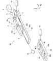
- FIG. 1A is a configuration diagram of a laser welding apparatus A including the optical scanning apparatus 2 according to the first embodiment.
- FIG. 2 is a plan view showing the locus of the laser beam L by the optical scanning device 2.
- the laser welding apparatus A of the present embodiment laser welds two metal workpieces W1 and W2 in a state where they are butted against each other.
- the welding device A includes a laser light irradiation device 1 (oscillator or the like) (light source) that irradiates the laser light L, and an optical scanning device 2 that scans the laser light L along the interface W12 of the workpieces W1 and W2. ing.
- the laser welding apparatus A includes an f ⁇ lens as a condensing lens for the laser beam L, which is designed so that the scanning speed is constant at the peripheral portion and the central portion of the lens. May be good.
- the laser beam L is wobbling along the interface W12. That is, the laser beam L is drawn (scanned) with a locus that combines circular motion and linear motion.
- the optical scanning device 2 illustrated in FIG. 1A has a rotary machine 10 (first rotary machine) and a rotary mirror 12 that carry out the circular motion, and two galvanometer mirrors 14 and 15 that carry out the linear motion. There is. On the irradiation surface of the laser beam L, one of the galvano mirrors 14 and 15 is responsible for scanning in the X-axis direction, and the other is responsible for scanning in the Y-axis direction.
- the rotary machine 10 includes a rotary shaft 11 that rotates around a rotary shaft R.
- the rotating machine 10 may be a spindle motor or an air turbine capable of rotating the rotating shaft 11 at high speed.
- the rotating machine 10 may be capable of rotating at a high speed of 100,000 [rpm] or more, for example.
- the X, Y, and Z axes shown in some figures are provided for convenience of explanation.
- the Y-axis indicates a direction parallel to the rotation axis R, and the X-axis and the Z-axis indicate a direction perpendicular to each other and perpendicular to the Y-axis.
- the XY plane corresponds to the horizontal plane and the Z axis corresponds to the vertical direction.
- the rotary mirror 12 is attached to the tip of the rotary shaft 11.
- the rotary mirror 12 is preferably a small circular mirror.
- the normal of the reflecting surface 12a of the rotating mirror 12 is inclined with respect to the rotating shaft R of the rotating shaft 11 (details will be described later).
- the laser beam L incident on the reflecting surface 12a of the rotating rotating mirror 12 is reflected at a certain angle and draws a circular locus. That is, the laser beam L reflected by the reflecting surface 12a of the rotating mirror 12 makes a circular motion.
- Galvano mirrors 14 and 15 move the circularly moving laser beam L in the XY planes set on the workpieces W1 and W2. That is, the galvanometer mirrors 14 and 15 play a role of linearly moving the circularly moving laser beam L on a plane along the interface W12. If the galvano mirrors 14 and 15 are used to make a circular motion of the laser beam L, it is necessary to rotate (vibrate) the galvano mirrors 14 and 15 finely at high speed, but the vibration is limited to about 1000 [Hz]. is there.
- the laser beam L reflected by the rotating mirror 12 is once reflected by the reflecting surface 13a of the optical path adjusting mirror 13 and then incident on the galvano mirror 14.
- a configuration may be adopted in which the distance D between the reflecting surface 13a of the optical path adjusting mirror 13 and the reflecting surface 12a of the rotating mirror 12 is variable.
- the angle between the normal of the reflecting surface 12a of the rotating mirror 12 and the rotating axis R of the rotating shaft 11 is ⁇ [rad]
- the optical path length from the reflecting surface 12a to the workpieces W1 and W2 is S [mm].
- a circle having a radius of ⁇ ⁇ S [mm] can be drawn on the target surfaces of the works W1 and W2.
- FIG. 1B is a modification of the laser welding apparatus A shown in FIG. 1A.
- the positions of the optical path adjusting mirror 13 and the optical scanning device 2 may be interchanged with each other.
- the optical scanning device 2 since the optical scanning device 2 can be arranged so as to be closer to the laser light irradiating device 1, the rigidity of the optical scanning device 2 can be more easily secured.
- an effect that the light reflected by the reflecting surface 12a of the rotating mirror 12 can be stabilized from the optical axis can be obtained.
- the locus of this circle is originally a perfect circle.
- the laser light L emitted from the laser light irradiation device 1 cannot be reflected in the same direction, it is necessary to incline the normal line of the reflection surface 12a with respect to the optical axis of the laser light L, although it is minute. is there. Therefore, the locus of the laser beam L becomes slightly elliptical. In the case of laser welding, even an ellipse of this size does not affect the welding performance, so it can be said that the shape collapses to a negligible level.
- the rotary mirror 12 attached to the tip of the rotary shaft 11 of the rotary machine 10 can draw a circle of the laser beam L at high speed, and thus is combined with the galvano mirrors 14 and 15.
- the wobbling locus as shown in FIG. 2 can be drawn at high speed, and the workpieces W1 and W2 can be satisfactorily laser welded in a short time.
- the galvano mirrors 14 and 15 are responsible for the linear motion of wobbling, but instead of the galvano mirrors 14 and 15, for example, a moving device for moving the workpieces W1 and W2 in a plane may be adopted. ..
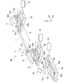
- FIG. 1C shows a laser adopting a configuration in which the distance D between the reflecting surface 13a of the optical path adjusting mirror 13 and the reflecting surface 12a of the rotating mirror 12 and the optical path length S from the reflecting surface 12a to the workpieces W1 and W2 are variable.
- the workpieces W1 and W2 are arranged on the workpiece moving apparatus 50.
- the laser welding device A2 provides a folded mirror 16 that folds back the optical path of the laser beam L so that the laser beam L reflected by the reflecting surface 13a of the optical path adjusting mirror 13 is scanned along the interface W12 of the workpieces W1 and W2. I have.
- the work moving device 50 includes a movable table 50a on which the works W1 and W2 are placed, and a shaft 50b that penetrates the movable table 50a and extends in the Y-axis direction.
- the movable table 50a can be moved along the shaft 50b by the control device 51.
- the work moving device 50 movable table 50a
- the laser light L can be scanned along the Y direction at the interface W12 of the works W1 and W2.
- the optical scanning apparatus 2 is parallel to the optical path adjusting mirror 13 that reflects the light reflected by the reflecting surface 12a of the rotating mirror 12 (along the Y-axis direction).
- a moving stage 70 (third moving stage) for moving the optical path adjusting mirror 13 and a control device 71 (third control device) for controlling the movement of the moving stage 70 are further provided.
- the moving stage 70 includes a base 70a, a movable table 70b that can move horizontally with respect to the base 70a, and a mirror holder 70c that is fixed to the movable table 70b and holds the optical path adjustment mirror 13.
- the movable table 70b can be moved on the base 70a in parallel with the rotation axis R (along the Y-axis direction) by the control device 71.
- the distance D between the reflecting surface 13a of the optical path adjusting mirror 13 and the reflecting surface 12a of the rotating mirror 12 is adjusted by the movement of the moving stage 70, and the optical path length S is adjusted so that the circle drawn on the work interface W12 is formed.
- the radius can be changed.
- scanning in the Y-axis direction at the work interface W12 can also be performed. Therefore, wobbling welding as illustrated in FIG. 2 can be performed at high speed on the work interface W12.
- the scanning width (welding width) at the work interface W12 can be changed by adjusting the optical path length S during the irradiation of the laser beam L.
- the optical scanning device 2 of FIG. 1C since the distance D can be adjusted while the position of the rotating machine 10 (rotating mirror 12) is fixed, it is easier to maintain the direction of the rotating shaft R of the rotating shaft 11.
- the radius of the circle drawn on the work interface W12 can be changed by adjusting the optical path length S, so that even when the mounting accuracy of the rotating mirror 12 on the rotating shaft 11 is not sufficient, The irradiation position of the laser beam L at the work interface W12 can be appropriately adjusted. As a result, the step of attaching the rotary mirror 12 to the rotary shaft 11 can be facilitated. Further, by adjusting the optical path length S, it is possible to obtain the optimum welding width (spot diameter and wobble width) and the penetration depth according to the material of the work and the welding form.
- the rotary machine 10, the work moving device 50, and the moving stage 70 may be controlled by one control device.
- the speed and width of the circular motion and the translational motion of the wobbling can be comprehensively adjusted by one control device, finer control of the wobbling becomes possible.
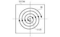
- FIG. 7 shows a spiral locus of the laser beam L (reflected light L2) on the reflecting surface 13a of the optical path adjusting mirror 13.
- the laser welding device A2 while irradiating the laser beam L, gradually reduce the distance D between the reflecting surface 12a of the rotating mirror 12 and the reflecting surface 13a of the optical path adjustment mirror 13 while fixing the positions of the workpieces W1 and W2. By separating them from each other, a spiral locus as illustrated in FIG. 7 can be drawn.
- FIG. 1D is a configuration diagram showing an example A3 of a laser welding apparatus adopting a configuration in which the optical path length S from the reflecting surface 12a to the workpieces W1 and W2 is variable.
- the laser welding apparatus A3 shown in FIG. 1D is different from the welding apparatus A2 described above in that the relative positional relationship between the reflecting surface 12a and the reflecting surface 13a is fixed, and the distance D is invariant. Since the configurations of the folding mirror 16 and the work moving device 50 are the same as those of the welding device A2, the description thereof will be omitted.
- the optical scanning apparatus 2 is parallel to the optical path adjusting mirror 13 that reflects the light reflected by the reflecting surface 12a of the rotating mirror 12 (along the Y-axis direction).
- a moving stage 80 fourth moving stage
- a control device 81 fourth control device
- the moving stage 80 includes a base 80a, a movable table 80b that can move horizontally with respect to the base 80a, a mirror holder 70c that is fixed to the movable table 80b and holds the optical path adjustment mirror 13, and a rotary machine 10 that is fixed to the movable table 80b.
- On the movable table 80b the relative positional relationship between the rotating machine 10 and the optical path adjusting mirror 13 (between the reflecting surface 12a and the reflecting surface 13a) is fixed.
- the movable table 80b can be moved on the base 80a in parallel with the rotation axis R (along the Y-axis direction) by the control device 81.
- the optical path length S from the reflecting surface 12a to the workpieces W1 and W2 (more directly, the optical path length from the reflecting surface 13a to the workpieces W1 and W2) is adjusted by moving the moving stage 80, thereby drawing on the work interface W12.
- the radius of the circle to be made can be changed.
- scanning in the Y-axis direction at the work interface W12 can also be performed. Therefore, wobbling welding as illustrated in FIG. 2 can be performed at high speed on the work interface W12.
- the scanning width (welding width) at the work interface W12 can be changed by adjusting the optical path length S during the irradiation of the laser beam L.
- the radius of the circle drawn on the work interface W12 can be changed by adjusting the optical path length S, so that the mounting accuracy of the rotating mirror 12 on the rotating shaft 11 is accurate. Is not sufficient, the irradiation position of the laser beam L at the work interface W12 can be appropriately adjusted. As a result, the process of attaching the rotary mirror 12 to the rotary shaft 11 can be simplified. Further, by adjusting the optical path length S, it is possible to obtain the optimum welding width (spot diameter and wobble width) and the penetration depth according to the material of the work and the welding form.
- the rotary machine 10, the work moving device 50, and the moving stage 80 may be controlled by one control device. In this case, since the speed and width of the circular motion and the translational motion of the wobbling can be comprehensively adjusted by one control device, finer control of the wobbling becomes possible.
- the optical scanning device and welding that are resistant to disturbance (vibration, etc.) Equipment can be provided. Further, since the distance D between the reflecting surface 12a of the rotating mirror 12 and the reflecting surface 13a of the optical path adjusting mirror 13 does not change even while the optical path length S is being adjusted by moving the moving stage 80, the laser on the reflecting surface 13a The magnitude of the locus of the light L is constant. Therefore, the size of the optical path adjustment mirror 13 can be suppressed to the minimum necessary, and the light scanning device 2 can be reduced in weight.
- the laser welding device A3 may include a condenser lens FL between the laser light irradiation device 1 and the rotating mirror 12.
- the optical path length from the laser light irradiation device 1 to the workpieces W1 and W2 does not change even while the optical path length S is being adjusted by moving the moving stage 80, the light is focused on the interface W12.
- the focused state of the lens FL can be maintained. That is, regardless of the adjustment operation of the optical path length S, the interface W12 can be stably irradiated with the laser beam having a high energy density.
- FIG. 3 is a diagram showing the positional relationship between the rotary machine 10, the rotary mirror 12, and the laser beam L according to the first embodiment.
- the normal line N of the reflecting surface 12a of the rotating mirror 12 is tilted at a first angle ⁇ 1 with respect to the optical axis of the incident light L1 incident on the reflecting surface 12a.
- the rotation axis R of the rotation shaft 11 is tilted at a second angle ⁇ 2 with respect to the normal line N of the reflection surface 12a.
- the magnitude (absolute value) of the first angle ⁇ 1 and the second angle ⁇ 2 are different.
- the first angle ⁇ 1 is larger than the second angle ⁇ 2.
- the optical axis of the incident light L1 is tilted with respect to the rotation axis R of the rotation shaft 11. That is, the optical axis of the incident light L1 and the rotation axis R of the rotation shaft 11 do not match.
- the incident position P of the incident light L1 on the reflecting surface 12a of the rotating mirror 12 coincides with the central position C through which the rotating shaft R of the rotating shaft 11 passes.
- the incident angle of the incident light L1 (first angle ⁇ 1) and the reflection angle of the reflected light L2 are the same with respect to the normal line N of the reflecting surface 12a passing through the incident position P.
- the normal line N of the reflection surface 12a rotates with an inclination of a second angle ⁇ 2 with respect to the rotation axis R of the rotation shaft 11.
- the reflected light L2 forms a conical reflection region 20 having an apex angle four times the second angle ⁇ 2 at the incident position P. That is, the locus of the bottom surface of the reflection region 20 (cone) becomes the locus of the circle described above.
- FIG. 4 shows the circular locus of the laser light L (reflected light L2) on the reflecting surface 13a of the optical path adjusting mirror 13.
- the optical scanning device 2 includes a rotary machine 10 including a rotary shaft 11 and a rotary mirror 12 attached to the tip of the rotary shaft 11, and is a method of a reflecting surface 12a of the rotary mirror 12.
- the line N is tilted at a first angle ⁇ 1 with respect to the optical axis of the incident light L1 incident on the reflecting surface 12a, and the rotating axis R of the rotating shaft 11 is a second angle with respect to the normal line N of the reflecting surface 12a. Since it is tilted at ⁇ 2, high-speed drawing (scanning) of a circular locus using the rotating machine 10 is possible.
- FIG. 5 shows a reflection region 20 of the reflected light L2 when the first angle ⁇ 1 and the second angle ⁇ 2 are equal.
- the first angle ⁇ 1 and the second angle ⁇ 2 are equal, and the optical axis of the incident light L1 and the rotation axis R of the rotation shaft 11 coincide with each other.
- the reflection region 20 of the reflected light L2 is formed around the optical axis of the incident light L1
- the optical path adjusting mirror 13 and the like illustrated in FIGS. 1A to 1C are placed around the incident light L1 (that is, the laser light irradiation device 1). It is necessary to devise such as arranging in a ring around (around). That is, a more complicated structure is required for the optical element on the downstream side of the rotating mirror 12.
- the first angle ⁇ 1 and the second angle ⁇ 2 are set so that the incident light L1 (that is, the laser light irradiation device 1) does not overlap the reflection region 20 of the reflected light L2. Should be set. Even when the rotation axis R of the rotating shaft 11 is translated (eccentric) with respect to the optical axis of the incident light L1, as long as the first angle ⁇ 1 and the second angle ⁇ 2 are equal, the rotation of the optical axis of the incident light L1 In addition, a reflection region 20 of the reflected light L2 is formed. In order to avoid the above complication, it is preferable that the first angle ⁇ 1 and the second angle ⁇ 2 are different regardless of whether the optical axis of the incident light L1 and the rotation axis R of the rotating shaft 11 match or do not match.
- the incident position P of the incident light L1 on the reflecting surface 12a of the rotating mirror 12 may coincide with the central position C through which the rotating shaft R of the rotating shaft 11 passes.
- the rotating shaft mounting surface 12b opposite to the reflecting surface 12a of the rotating mirror 12 may be a flat surface orthogonal to the rotating shaft R of the rotating shaft 11. According to this configuration, the rotary mirror 12 can be easily attached to the tip of the rotary shaft 11, and the assembleability of the optical scanning device 2 is improved. Further, each of the above-mentioned optical scanning devices 2 may be configured to move the incident position P of the incident light L1 on the reflecting surface 12a of the rotating mirror 12. When the laser light L is scanned along the interface W12 of the first work W1 and the second work W2 using each optical scanning device 2, the incident position P of the incident light L1 on the reflecting surface 12a of the rotating mirror 12 is moved. As a result, it is possible to prevent the incident light L1 from being continuously irradiated to a specific point on the reflecting surface 12a for a long time.
- FIG. 6A is a configuration diagram of the optical scanning apparatus 2 according to the second embodiment.
- the optical scanning device 2 illustrated in FIG. 6A is different from the first embodiment in that the rotating machine 10 is mounted on the moving device 30. Due to the movement of the moving device 30 in a plane perpendicular to the rotating shaft R, the distance between the incident position P of the incident light L1 and the central position C through which the rotating shaft R of the rotating shaft 11 passes is reduced on the reflecting surface 12a of the rotating mirror 12. It is variable.
- the thickness of the rotating mirror 12 two-dot chain line
- solid line the thickness of the rotating mirror 12
- the moving device 30 can be exemplified as, for example, a guide device that can move in one direction (regardless of a straight line or a curved line), a moving device that can move in two or more directions, and the like.
- the moving device 30 can also be driven under the control of the control device 31 to move the incident position P with respect to the central position C while the laser beam L is irradiating the rotating mirror 12.
- the laser beam L is continuously irradiated to a specific point on the reflecting surface 12a for a long time.
- the reflective surface 12a may be distorted by heat.
- the incident light L1 is incident on the reflecting surface 12a of the rotating mirror 12.
- the position P may be moved. For example, as shown by the alternate long and short dash line in FIG.
- the control device 31 moves the incident position P of the incident light L1 on the reflecting surface 12a of the rotating mirror 12 between the center position C through which the rotation axis R of the rotation shaft 11 passes and the position deviated from the center position C.
- the program may be incorporated in.
- the center position C can be kept in an appropriate temperature range by controlling the incident position P to be shifted from the center position C based on the result of the temperature measurement of the center position C by the control device 31.
- the temperature of the center position C can be measured by, for example, a temperature sensor (preferably a non-contact type) (not shown).
- the optical scanning device 2 illustrated in FIG. 6A is configured so that the rotating machine 10 can be moved by the moving device 30, the optical axis of the incident light L1 of the laser beam L may be movable.
- a mirror or a lens may be arranged between the laser light irradiation device 1 and the rotating mirror 12.
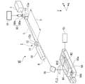
- FIG. 6B is a modification of the optical scanning apparatus 2 according to the second embodiment, and a configuration diagram of a laser welding apparatus A4 including the modified example.
- the rotary mirror 12 and the laser light irradiation apparatus 1 are configured to be movable in two directions (X-axis and Z-axis directions) perpendicular to the rotation axis R. Since the configurations of the folding mirror 16 and the work moving device 50 are the same as those of the welding devices A2 and A3, the description thereof will be omitted.
- the optical scanning device 2 moves the rotary machine 10 (rotary mirror 12) along a plane (XZ plane) perpendicular to the rotation axis R, and a moving stage 40 (first moving stage). ), And a control device 41 (first control device) that controls the movement of the movement stage 40.
- the control device 41 moves the incident position P of the incident light L1 on the reflecting surface 12a of the rotating mirror 12 between the center position C through which the rotation axis R of the rotation shaft 11 passes and the position deviated from the center position C.
- the movement of the movement stage 40 can be controlled.
- the optical scanning apparatus 2 includes a laser beam irradiating apparatus 1 (light source) that emits incident light L1 and a laser beam irradiating apparatus along a plane (XZ plane) perpendicular to the rotation axis R.
- a moving stage 42 (second moving stage) for moving 1 and a control device 43 (second control device) for controlling the movement of the moving stage 42 are further provided.
- the control device 43 moves the incident position P of the incident light L1 on the reflecting surface 12a of the rotating mirror 12 between the center position C through which the rotation axis R of the rotation shaft 11 passes and the position deviated from the center position C.
- the movement of the movement stage 42 can be controlled.
- the moving stages 40 and 42 have the same structure except for the bracket described later.
- the moving stage 40 (42) includes a first base 40a (42a), a movable table 40b (42b) that can move horizontally with respect to the base 40a (42a), and a second base fixed to the movable table 40b (42b). It includes a 40c (42c) and a movable table 40d (42d) that can be vertically moved with respect to the second base 40c (42c).
- the moving stage 40 further includes a bracket 40e that is fixed to the movable table 40d and holds the rotating machine 10.
- the laser light irradiation device 1 is fixed to the movable table 42d.
- the control device 41 (43) can control the movement of the movable table 40b (42b) with respect to the first base 40a (42a) in the X-axis direction. Further, the control device 41 (43) can control the movement of the movable table 40d (42d) with respect to the second base 40c (42c) in the Z-axis direction.
- the movement of the rotating machine 10 by the moving stage 40 and the movement of the laser light irradiation device 1 by the moving stage 42 are performed without tilting the rotating shaft R of the rotating shaft 11. Therefore, regardless of the movement of the rotary machine 10 and the laser light irradiation device 1, the rotary mirror 12 attached to the tip of the rotary shaft 11 can continue to rotate stably.
- the incident position P of the incident light L1 on the reflecting surface 12a of the rotating mirror 12 can be adjusted.
- the laser light irradiation device 1 fixed to the moving stage 42 by the control device 43 along a plane (XZ plane) perpendicular to the rotation axis R the incident light on the reflection surface 12a of the rotation mirror 12
- the incident position P of L1 can be adjusted.
- the control device 51 controls the incident position P to be shifted from the center position C based on the result of the temperature measurement at the center position C. Position C can be kept in an appropriate temperature range.
- the optical scanning device 2 of the laser welding device A4 may include at least one of the moving stages 40 and 42 illustrated in FIG. 6B.
- the moving stage 40 may include at least one of a portion (40a, 40b) responsible for movement in the X direction and a portion (40c, 40d) responsible for movement in the Z direction illustrated in FIG. 6B.
- the moving stage 42 may include at least one of a portion (42a, 42b) responsible for movement in the X direction and a portion (42c, 42d) responsible for movement in the Z direction illustrated in FIG. 6B.
- the condenser lens FL2 may be arranged between the folded mirror 16 and the works W1 and W2.
- the interface W12 can be stably irradiated with the laser light having a higher energy density.
- FIG. 6C is a modification of the optical scanning apparatus 2 according to the second embodiment, and a configuration diagram of a laser welding apparatus A5 including the modified example.
- the laser welding apparatus A4 illustrated in FIG. 6C is capable of shifting the optical axis of the laser beam L incident on the reflecting surface 12a of the rotating mirror 12 in a direction perpendicular to the rotating axis R (for example, the X-axis direction in FIG. 6C). It is configured. Since the configurations of the folding mirror 16 and the work moving device 50 are the same as those of the welding devices A2 to A4, the description thereof will be omitted.
- the optical scanning apparatus 2 rotates the transmission plate 60a arranged on the optical axis of the laser light L (incident light L1) and rotates the transmission plate 60a to parallel the optical axis.
- a transmission plate rotating device 60 including a second rotating machine 60b to be moved, and a rotation control device 61 for controlling the rotation of the second rotating machine 60b are provided.
- the rotation control device 61 the incident position P of the incident light L1 on the reflecting surface 12a of the rotating mirror 12 moves between the center position C through which the rotation axis R of the rotation shaft 11 passes and the position deviated from the center position C.
- the rotation of the second rotary machine 60b can be controlled.
- the transmission plate 60a is a plate that is transparent to the laser beam L.
- the incident angle of the laser light L with respect to the transmission plate 60a is other than 0 degrees, the laser light L is refracted by the transmission plate 60a.
- the optical axis of the laser beam L moves in parallel with the direction perpendicular to the rotation axis R (Y axis in FIG. 6C). That is, the rotation control device 61 controls the angle of the transmitting plate 60a with respect to the optical axis of the laser beam L through the second rotating machine 60b to adjust the incident position P of the incident light L1 on the reflecting surface 12a of the rotating mirror 12. it can. Since the operation of the transmission plate rotating device 60 does not involve the movement of the rotating machine 10, the rotating mirror 12 attached to the tip of the rotating shaft 11 can continue to rotate stably.
- the rotation control device 61 controls the incident position P to be shifted from the center position C based on the result of the temperature measurement at the center position C. Position C can be kept in an appropriate temperature range.
- the condenser lens FL2 may be arranged between the folded mirror 16 and the works W1 and W2.
- the interface W12 can be stably irradiated with the laser light having a higher energy density.
- the rotating shaft mounting surface 12b on the opposite side of the rotating mirror 12 from the reflecting surface 12a is an inclined surface parallel to the reflecting surface 12a and inclined with respect to the rotating shaft R of the rotating shaft 11. You may be.
- the thickness of the rotary mirror 12 can be reduced and the weight can be reduced as compared with the form in which the rotary shaft mounting surface 12b illustrated in FIG. 5 is orthogonal to the rotary shaft R. Therefore, the rotary mirror 12 can be easily rotated at high speed.
- Examples of the laser light irradiation device 1 described above include a normal single-mode laser and a single-mode fiber laser.
- a collimator unit may be arranged between the laser light irradiation device 1 and the rotary mirror 12 in order to obtain parallel light.
- FIGS. 9A to 9D There are various forms of welding of the workpieces W1 and W2 as shown in FIGS. 9A to 9D.
- FIG. 9 (a) is an example of butt welding, (b) is an example of lap welding, (c) is an example of worship welding, and (d) is an example of LIB (lithium ion battery) welding.
- the optical scanning device 2 according to each of the above-described embodiments can be used not only for butt welding but also for various types of welding as illustrated in FIGS. 9B to 9D.
- the surface of one of the works W1 is irradiated with laser light to perform welding at the interface W12.
- the optical scanning apparatus 2 and the welding apparatus provided with the optical scanning apparatus 2 can irradiate laser light at a desired position at high speed, they can be applied to welding of workpieces W1 and W2 of various materials.
- the workpieces W1 and W2 are a highly reflective material such as copper or aluminum that is difficult to weld, the above-mentioned wobbling welding is preferable.
- the high-speed laser light irradiation by the optical scanning device 2 can be applied to, for example, a manufacturing process of a lithium ion battery.
- a manufacturing process of a lithium ion battery in order to seal the can package into which the electrolytic solution is injected, there is a step (sealing step) in which a metal lid is overlapped and welded to the liquid injection port of the can package.
- welding defects due to adhesion of the electrolytic solution are very likely to occur, which makes stable mass production of lithium ion batteries difficult.
- the electrolytic solution adhering around the liquid injection port is effectively removed by using the optical scanning device 2 according to each of the above-described embodiments at the interface (contact surface) between the liquid injection port and the metal lid. be able to.
- the above-mentioned laser welding devices A2 and A3 to irradiate the interface (contact surface) between the injection port and the metal lid with high-speed laser light in a spiral locus as illustrated in FIG. , The electrolytic solution adhering around the injection port can be effectively removed.
- the laser beam is scanned along the peripheral edge of the injection port using the optical scanning device 2 according to each of the above-described embodiments. May be good.
- the electrolytic solution adhering around the liquid injection port can be removed in advance after the electrolytic solution is injected from the liquid injection port of the can package and before the sealing step with the metal lid is performed (preliminary irradiation step). ).
- the welding strength between the metal lid and the liquid injection port in the sealing process can be further increased.
- a cap body having the liquid injection port is superposed on the metal can having the opening so as to close the opening, and the interface between the metal can and the cap body is used by using the optical scanning device 2 according to each of the above-described embodiments.
- the can package can be obtained by scanning the laser beam along the can package. More specifically, after housing a lithium-ion battery component such as an electrode coil in a metal can, a can package having a liquid injection port is formed by welding the peripheral edge of the opening of the metal can and a cap body having a liquid injection port. Can be obtained (can package manufacturing process). Welding in the can package manufacturing step described above, electrolytic solution removal in the pre-irradiation step, and welding in the sealing step can be realized by the same optical scanning device 2.
- the material of the metal can, the cap body, and the metal lid may be any of aluminum, stainless steel, and iron. Typically, the materials of the metal can, the cap body, and the metal lid are the same. High-speed wobbling of laser light using the optical scanning device 2 according to each of the above-described embodiments is suitable for welding these metals.
- the reflecting surface of the rotating mirror 12 is performed.
- the incident position P of the incident light L1 in 12a may be moved. In this case, the heat distortion of the reflective surface 12a is suppressed, and as a result, the welding / electrolytic solution removal work for a long time becomes possible.
- the rotation axis R is used.
- the scanning width of light at the interface between welding targets or around the liquid injection port may be changed. In this case, optimum scanning (welding) can be performed according to the material to be irradiated with the laser beam L and the welding form.
- the optical scanning device 2 may be applied to other devices that irradiate light such as ultraviolet rays (UV).
- UV ultraviolet rays
- an optical scanning device capable of high-speed scanning of a locus including a circular motion, an optical scanning method, and a method for manufacturing a lithium ion battery.
- Optical scanning device 10 Rotating machine 11 ... Rotating shaft 12 ... Rotating mirror 12a ... Reflecting surface 12b ... Rotating shaft mounting surface C ... Center position L1 ... Incident light N ... Normal line P ... Incident position R ... Rotating axis ⁇ 1 ... 1 angle ⁇ 2 ... 2nd angle
Landscapes
- Physics & Mathematics (AREA)
- Optics & Photonics (AREA)
- General Physics & Mathematics (AREA)
- Engineering & Computer Science (AREA)
- Plasma & Fusion (AREA)
- Mechanical Engineering (AREA)
- Laser Beam Processing (AREA)
Abstract
回転シャフトを備える第一回転機と、前記回転シャフトの先端に取り付けられた回転ミラーと、を備える光走査装置を提供する。前記回転ミラーの反射面の法線は、前記反射面に入射する入射光の光軸に対して第1角度で傾いており、前記回転シャフトの回転軸は、前記反射面の法線に対して第2角度で傾いており、前記第1角度は、前記第2角度よりも大きい。
Description
本発明は、光走査装置、光走査方法、及びリチウムイオン電池の製造方法に関するものである。
本願は、2019年3月8日に、日本に出願された特願2019-042639号に基づき優先権を主張し、その内容をここに援用する。
本願は、2019年3月8日に、日本に出願された特願2019-042639号に基づき優先権を主張し、その内容をここに援用する。
下記特許文献1には、複数の金属製のワーク同士を重ね合わせた状態又は突き合わせた状態でこれらを接合するレーザー溶接装置が開示されている。このレーザー溶接装置は、二枚の駆動ミラーでレーザー光を反射し、ワークにレーザー光を照射している。このような二枚の駆動ミラーを使った装置は、ガルバノスキャナとも称される。二枚の駆動ミラーそれぞれをモータで適切な角度に回転させることで、レーザー光を狙った位置に照射することができる。たとえば、レーザー光を予め設定された軌跡(たとえば円状又は螺旋状)に沿って走査することも可能である。
レーザー溶接において、ウォブリングと称される円運動と直線運動を組み合わせたような軌跡(螺旋運動のような軌跡)で、溶接対象であるワーク同士の界面に対し、ある程度の幅を持った溶接を行う場合がある。このような場合、スパッタと呼ばれる飛散物を抑制したり、溶接部位の強度を高めるために、極短時間で高い熱量を局所的に与える必要がある。上記軌跡に沿って高速で描画(走査)することが望ましい。
上記ガルバノスキャナ方式では、レーザー光を円運動させるために二枚の駆動ミラーを高速で細かく回転(振動)させる。この方式においてレーザー光の照射範囲をできるだけ大きくとるためには、二枚の駆動ミラーのいずれか一方の面積を大きくしなければならない。この場合、二枚の駆動ミラーの少なくとも一方の重量が重くなり、上記のような微細な高速振動を正確に行うことが極めて困難である。
本発明は、上記問題点に鑑みてなされたものであり、円運動を含む軌跡の高速走査が可能な光走査装置、光走査方法、及びリチウムイオン電池の製造方法の提供を目的とする。
(1)本発明の一態様に係る光走査装置は、回転シャフトを備える第一回転機と、前記回転シャフトの先端に取り付けられた回転ミラーと、を備え、前記回転ミラーの反射面の法線は、前記反射面に入射する入射光の光軸に対して第1角度で傾いており、前記回転シャフトの回転軸は、前記反射面の法線に対して第2角度で傾いており、前記第1角度は、前記第2角度よりも大きい。
(2)上記(1)に記載された光走査装置であって、前記入射光の光軸と前記回転シャフトの回転軸が一致していなくてもよい。
(3)上記(1)又は(2)に記載された光走査装置であって、前記回転ミラーの反射面における前記入射光の入射位置Pは、前記回転シャフトの回転軸が通る中心位置と一致していてもよい。
(4)上記(1)又は(2)に記載された光走査装置であって、前記回転ミラーの反射面における前記入射光の入射位置Pは、前記回転シャフトの回転軸が通る中心位置からずれていてもよい。
(5)上記(1)~(3)に記載された光走査装置であって、前記回転軸に垂直な平面に沿って前記第一回転機を移動させる第一移動ステージと、前記第一移動ステージの移動を制御する第一制御装置と、をさらに備え、前記第一制御装置は、前記回転ミラーの反射面における前記入射光の入射位置Pが、前記回転シャフトの回転軸が通る中心位置と、前記中心位置からずれた位置との間で移動するように、前記第一移動ステージの移動を制御してもよい。
(6)上記(1)~(3)に記載された光走査装置であって、前記入射光の光軸上に配置される透過板と、前記透過板を回転させて前記光軸を平行移動させる第二回転機と、を備える透過板回転装置と、前記第二回転機の回転を制御する回転制御装置と、をさらに備え、前記回転制御装置は、前記回転ミラーの反射面における前記入射光の入射位置Pが、前記回転シャフトの回転軸が通る中心位置と、前記中心位置からずれた位置との間で移動するように、前記第二回転機の回転を制御してもよい。
(7)上記(1)~(3)に記載された光走査装置であって、前記入射光を発する光源と、前記回転軸に垂直な平面に沿って前記光源を移動させる第二移動ステージと、前記第二移動ステージの移動を制御する第二制御装置と、をさらに備え、前記第二制御装置は、前記回転ミラーの反射面における前記入射光の入射位置Pが、前記回転シャフトの回転軸が通る中心位置と、前記中心位置からずれた位置との間で移動するように、前記第二移動ステージの移動を制御してもよい。
(8)上記(1)~(7)に記載された光走査装置であって、前記回転ミラーの反射面で反射した光を反射する光路調整ミラーと、前記回転軸に対して平行に前記光路調整ミラーを移動させる第三移動ステージと、前記第三移動ステージの移動を制御する第三制御装置と、をさらに備えていてもよい。
(9)上記(1)~(7)に記載された光走査装置であって、前記回転ミラーの反射面で反射した光を反射する光路調整ミラーと、前記回転軸に対して平行に前記第一回転機及び前記光路調整ミラーを一体として移動させる第四移動ステージと、前記第四移動ステージの移動を制御する第四制御装置と、をさらに備えていてもよい。
(10)上記(1)~(9)に記載された光走査装置であって、前記回転ミラーの前記反射面と反対側の回転シャフト取付け面は、前記回転シャフトの回転軸に対して直交した平坦面であってもよい。
(11)上記(1)~(9)に記載された光走査装置であって、前記回転ミラーの前記反射面と反対側の回転シャフト取付け面は、前記反射面と平行且つ前記回転シャフトの回転軸に対して傾いた傾斜面であってもよい。
(12)本発明の一態様に係る光走査方法は、上記(1)~(11)のいずれかの光走査装置を用いて第一ワーク及び第二ワークの界面に沿ってレーザー光を走査する際に、前記回転ミラーの反射面における前記入射光の入射位置Pを移動させる。
(13)本発明の一態様に係る光走査方法は、上記(8)又は(9)光走査装置を用いて第一ワーク及び第二ワークの界面に沿ってレーザー光を走査する光走査方法であって、前記回転軸に対して平行に前記光路調整ミラーを移動することにより、前記界面における光の走査幅を変える。
(14)上記(12)~(13)に記載された光走査方法であって、前記第一ワーク及び前記第二ワークの少なくとも一方がアルミであってもよい。
(15)本発明の一態様に係るリチウムイオン電池の製造方法は、缶パッケージの注液口に金属蓋を重ね、上記(1)~(11)の光走査装置を用いて、前記注液口と前記金属蓋との界面に沿ってレーザー光を走査する。
(16)上記(15)に記載されたリチウムイオン電池の製造方法であって、前記金属蓋を前記電解液が注入された缶パッケージの注液口に重ねる前に、前記光走査装置を用いて前記注液口周縁に沿ってレーザー光を走査してもよい。
(17)上記(15)又は(16)に記載されたリチウムイオン電池の製造方法であって、開口を有する金属缶に、前記開口を閉塞するように前記注液口を有するキャップ体を重ね、前記光走査装置を用いて、前記金属缶と前記キャップ体との界面に沿ってレーザー光を走査して前記缶パッケージを得てもよい。
(18)上記(15)~(17)に記載されたリチウムイオン電池の製造方法であって、前記金属缶、前記キャップ体、及び前記金属蓋の材質は、アルミ、ステンレス、鉄のいずれかであってもよい。
(3)上記(1)又は(2)に記載された光走査装置であって、前記回転ミラーの反射面における前記入射光の入射位置Pは、前記回転シャフトの回転軸が通る中心位置と一致していてもよい。
(4)上記(1)又は(2)に記載された光走査装置であって、前記回転ミラーの反射面における前記入射光の入射位置Pは、前記回転シャフトの回転軸が通る中心位置からずれていてもよい。
(5)上記(1)~(3)に記載された光走査装置であって、前記回転軸に垂直な平面に沿って前記第一回転機を移動させる第一移動ステージと、前記第一移動ステージの移動を制御する第一制御装置と、をさらに備え、前記第一制御装置は、前記回転ミラーの反射面における前記入射光の入射位置Pが、前記回転シャフトの回転軸が通る中心位置と、前記中心位置からずれた位置との間で移動するように、前記第一移動ステージの移動を制御してもよい。
(6)上記(1)~(3)に記載された光走査装置であって、前記入射光の光軸上に配置される透過板と、前記透過板を回転させて前記光軸を平行移動させる第二回転機と、を備える透過板回転装置と、前記第二回転機の回転を制御する回転制御装置と、をさらに備え、前記回転制御装置は、前記回転ミラーの反射面における前記入射光の入射位置Pが、前記回転シャフトの回転軸が通る中心位置と、前記中心位置からずれた位置との間で移動するように、前記第二回転機の回転を制御してもよい。
(7)上記(1)~(3)に記載された光走査装置であって、前記入射光を発する光源と、前記回転軸に垂直な平面に沿って前記光源を移動させる第二移動ステージと、前記第二移動ステージの移動を制御する第二制御装置と、をさらに備え、前記第二制御装置は、前記回転ミラーの反射面における前記入射光の入射位置Pが、前記回転シャフトの回転軸が通る中心位置と、前記中心位置からずれた位置との間で移動するように、前記第二移動ステージの移動を制御してもよい。
(8)上記(1)~(7)に記載された光走査装置であって、前記回転ミラーの反射面で反射した光を反射する光路調整ミラーと、前記回転軸に対して平行に前記光路調整ミラーを移動させる第三移動ステージと、前記第三移動ステージの移動を制御する第三制御装置と、をさらに備えていてもよい。
(9)上記(1)~(7)に記載された光走査装置であって、前記回転ミラーの反射面で反射した光を反射する光路調整ミラーと、前記回転軸に対して平行に前記第一回転機及び前記光路調整ミラーを一体として移動させる第四移動ステージと、前記第四移動ステージの移動を制御する第四制御装置と、をさらに備えていてもよい。
(10)上記(1)~(9)に記載された光走査装置であって、前記回転ミラーの前記反射面と反対側の回転シャフト取付け面は、前記回転シャフトの回転軸に対して直交した平坦面であってもよい。
(11)上記(1)~(9)に記載された光走査装置であって、前記回転ミラーの前記反射面と反対側の回転シャフト取付け面は、前記反射面と平行且つ前記回転シャフトの回転軸に対して傾いた傾斜面であってもよい。
(12)本発明の一態様に係る光走査方法は、上記(1)~(11)のいずれかの光走査装置を用いて第一ワーク及び第二ワークの界面に沿ってレーザー光を走査する際に、前記回転ミラーの反射面における前記入射光の入射位置Pを移動させる。
(13)本発明の一態様に係る光走査方法は、上記(8)又は(9)光走査装置を用いて第一ワーク及び第二ワークの界面に沿ってレーザー光を走査する光走査方法であって、前記回転軸に対して平行に前記光路調整ミラーを移動することにより、前記界面における光の走査幅を変える。
(14)上記(12)~(13)に記載された光走査方法であって、前記第一ワーク及び前記第二ワークの少なくとも一方がアルミであってもよい。
(15)本発明の一態様に係るリチウムイオン電池の製造方法は、缶パッケージの注液口に金属蓋を重ね、上記(1)~(11)の光走査装置を用いて、前記注液口と前記金属蓋との界面に沿ってレーザー光を走査する。
(16)上記(15)に記載されたリチウムイオン電池の製造方法であって、前記金属蓋を前記電解液が注入された缶パッケージの注液口に重ねる前に、前記光走査装置を用いて前記注液口周縁に沿ってレーザー光を走査してもよい。
(17)上記(15)又は(16)に記載されたリチウムイオン電池の製造方法であって、開口を有する金属缶に、前記開口を閉塞するように前記注液口を有するキャップ体を重ね、前記光走査装置を用いて、前記金属缶と前記キャップ体との界面に沿ってレーザー光を走査して前記缶パッケージを得てもよい。
(18)上記(15)~(17)に記載されたリチウムイオン電池の製造方法であって、前記金属缶、前記キャップ体、及び前記金属蓋の材質は、アルミ、ステンレス、鉄のいずれかであってもよい。
上記本発明のいくつかの態様によれば、円運動を含む軌跡の高速走査が可能な光走査装置、光走査方法、及びリチウムイオン電池の製造方法を提供できる。
以下、本発明の実施形態について図面を参照して説明する。なお、以下の説明では、実施形態に係る光走査装置をレーザー溶接装置に適用した例を示す。
(第1実施形態)
図1Aは、第1実施形態に係る光走査装置2を備えるレーザー溶接装置Aの構成図である。図2は、光走査装置2によるレーザー光Lの軌跡を示す平面図である。
本実施形態のレーザー溶接装置Aは、図1Aに例示すように、金属製の2つのワークW1,W2を突き合わせた状態でこれらをレーザー溶接する。溶接装置Aは、レーザー光Lを照射するレーザー光照射装置1(発振機等)(光源)と、ワークW1,W2の界面W12に沿ってレーザー光Lを走査する光走査装置2と、を備えている。また、図1Aにおいて不図示であるが、レーザー溶接装置Aは、レーザー光Lの集光レンズとして、レンズ周辺部と中心部で走査速度が一定になるように設計されたfθレンズを備えていてもよい。
図1Aは、第1実施形態に係る光走査装置2を備えるレーザー溶接装置Aの構成図である。図2は、光走査装置2によるレーザー光Lの軌跡を示す平面図である。
本実施形態のレーザー溶接装置Aは、図1Aに例示すように、金属製の2つのワークW1,W2を突き合わせた状態でこれらをレーザー溶接する。溶接装置Aは、レーザー光Lを照射するレーザー光照射装置1(発振機等)(光源)と、ワークW1,W2の界面W12に沿ってレーザー光Lを走査する光走査装置2と、を備えている。また、図1Aにおいて不図示であるが、レーザー溶接装置Aは、レーザー光Lの集光レンズとして、レンズ周辺部と中心部で走査速度が一定になるように設計されたfθレンズを備えていてもよい。
本実施形態のレーザー溶接装置Aでは、図2に例示すように、界面W12に沿ってレーザー光Lをウォブリングさせる。つまり、レーザー光Lは、円運動と直線運動を組み合わせた軌跡で描画(走査)される。図1Aに例示す光走査装置2は、上記円運動を担う回転機10(第一回転機)及び回転ミラー12と、上記直線運動を担う2枚のガルバノミラー14,15と、を有している。レーザー光Lの照射面において、ガルバノミラー14,15のうちの一方がX軸方向の走査を担い、他方がY軸方向の走査を担う。
回転機10は、回転軸R周りに回転する回転シャフト11を備えている。この回転機10は、回転シャフト11を高速回転させることが可能なスピンドルモーターあるいはエアタービンなどであるとよい。回転機10は、たとえば、100000[rpm]以上の高速回転が可能であるとよい。
いくつかの図に示されているX,Y,Z軸は説明の便宜のために付されている。Y軸は回転軸Rに平行な方向を示し、X軸及びZ軸は互いに垂直であって且つY軸に垂直な方向を示している。典型的には、XY平面が水平面に対応し、Z軸が鉛直方向に対応する。
いくつかの図に示されているX,Y,Z軸は説明の便宜のために付されている。Y軸は回転軸Rに平行な方向を示し、X軸及びZ軸は互いに垂直であって且つY軸に垂直な方向を示している。典型的には、XY平面が水平面に対応し、Z軸が鉛直方向に対応する。
回転ミラー12は、回転シャフト11の先端に取り付けられている。回転ミラー12は、小型の円形ミラーであるとよい。回転ミラー12の反射面12aの法線は、回転シャフト11の回転軸Rに対して傾いている(詳しくは後述)。回転している回転ミラー12の反射面12aに入射したレーザー光Lは、ある角度を持って反射され、円状の軌跡を描画する。つまり、回転ミラー12の反射面12aで反射したレーザー光Lは、円運動する。
ガルバノミラー14,15は、この円運動するレーザー光Lを、ワークW1,W2上に設定したX-Y平面において移動させる。つまり、ガルバノミラー14,15は、円運動するレーザー光Lを、界面W12に沿って平面上に直線運動させる役割を担う。仮に、ガルバノミラー14,15のみで、レーザー光Lの円運動を行う場合、ガルバノミラー14,15を高速で細かく回転(振動)させる必要があるが、その振動は1000[Hz]程度が限界である。
回転ミラー12で反射したレーザー光Lは、一度、光路調整ミラー13の反射面13aで反射した後、ガルバノミラー14に入射する。光路調整ミラー13の反射面13aと回転ミラー12の反射面12aとの間の距離Dが可変である構成を採用してもよい。回転ミラー12の反射面12aの法線と、回転シャフト11の回転軸Rとの間の角度をθ[rad]、反射面12aからワークW1,W2までの光路長をS[mm]とすると、ワークW1,W2の対象面に、半径θ×S[mm]の円を描画することができる。距離Dを調整することにより、Sを調整し、描画する円の半径を変えることができる。
図1Bは、図1Aに示すレーザー溶接装置Aの変形例である。図1Bに例示するように、レーザー溶接装置Aにおいて、光路調整ミラー13及び光走査装置2(回転機10,回転シャフト11,回転ミラー12)の位置を相互に入れ替えてもよい。この場合、光走査装置2をレーザー光照射装置1により近づけるように配置できるため、光走査装置2の剛性をより確保しやすくできる。その結果、上述した効果に加えて、回転ミラー12の反射面12aで反射された光の光軸より安定させることができるという効果も得られる。
図1Bは、図1Aに示すレーザー溶接装置Aの変形例である。図1Bに例示するように、レーザー溶接装置Aにおいて、光路調整ミラー13及び光走査装置2(回転機10,回転シャフト11,回転ミラー12)の位置を相互に入れ替えてもよい。この場合、光走査装置2をレーザー光照射装置1により近づけるように配置できるため、光走査装置2の剛性をより確保しやすくできる。その結果、上述した効果に加えて、回転ミラー12の反射面12aで反射された光の光軸より安定させることができるという効果も得られる。
この円の軌跡は、本来は完全な円であることが望ましい。しかしながら、レーザー光照射装置1から照射されたレーザー光Lを同じ方向に反射することはできないため、微小ではあるが、レーザー光Lの光軸に対して反射面12aの法線を、傾ける必要がある。このため、レーザー光Lの軌跡は、微妙に楕円状となる。レーザー溶接の場合、この程度の楕円であっても溶接性能には影響しないため、無視してよい程度の形状の崩れと言える。
このように、上述した本実施形態によれば、回転機10の回転シャフト11の先端に取り付けた回転ミラー12によって、レーザー光Lの円を高速に描画できるため、ガルバノミラー14,15との組み合わせることで、図2に例示すようなウォブリング軌跡を高速で描画でき、ワークW1,W2を短時間で良好にレーザー溶接することができる。
なお、本実施形態では、ガルバノミラー14,15がウォブリングの直線運動を担っているが、ガルバノミラー14,15の代わりに、たとえば、ワークW1,W2を平面移動させる移動装置を採用してもよい。
なお、本実施形態では、ガルバノミラー14,15がウォブリングの直線運動を担っているが、ガルバノミラー14,15の代わりに、たとえば、ワークW1,W2を平面移動させる移動装置を採用してもよい。
図1Cは、光路調整ミラー13の反射面13aと回転ミラー12の反射面12aとの間の距離D、及び反射面12aからワークW1,W2までの光路長Sが可変である構成を採用したレーザー溶接装置の一例A2を示す構成図である。
図1Cに例示すレーザー溶接装置A2は、上述した溶接装置Aとは異なり、ワークW1,W2がワーク移動装置50の上に配置されている。また、レーザー溶接装置A2は、光路調整ミラー13の反射面13aで反射したレーザー光LがワークW1,W2の界面W12に沿って走査されるように、レーザー光Lの光路を折り返す折返しミラー16を備えている。
図1Cに例示すレーザー溶接装置A2は、上述した溶接装置Aとは異なり、ワークW1,W2がワーク移動装置50の上に配置されている。また、レーザー溶接装置A2は、光路調整ミラー13の反射面13aで反射したレーザー光LがワークW1,W2の界面W12に沿って走査されるように、レーザー光Lの光路を折り返す折返しミラー16を備えている。
ワーク移動装置50は、ワークW1,W2が載置される可動テーブル50aと、可動テーブル50aを貫通しY軸方向に延びるシャフト50bと、を備える。可動テーブル50aは、制御装置51により、シャフト50bに沿って移動可能である。
レーザー光Lを照射中にワーク移動装置50(可動テーブル50a)を移動させることにより、ワークW1,W2の界面W12において、レーザー光LをY方向に沿って走査することができる。
レーザー光Lを照射中にワーク移動装置50(可動テーブル50a)を移動させることにより、ワークW1,W2の界面W12において、レーザー光LをY方向に沿って走査することができる。
図1Cのレーザー溶接装置A2において、光走査装置2は、回転ミラー12の反射面12aで反射した光を反射する光路調整ミラー13と、回転軸Rに対して平行に(Y軸方向に沿って)光路調整ミラー13を移動させる移動ステージ70(第三移動ステージ)と、移動ステージ70の移動を制御する制御装置71(第三制御装置)と、をさらに備えている。
移動ステージ70は、ベース70aと、ベース70aに対して水平移動可能な可動テーブル70bと、可動テーブル70bに固定され光路調整ミラー13を保持するミラーホルダー70cと、を備える。可動テーブル70bは、制御装置71により、ベース70a上で回転軸Rに対して平行に(Y軸方向に沿って)移動可能である。
移動ステージ70は、ベース70aと、ベース70aに対して水平移動可能な可動テーブル70bと、可動テーブル70bに固定され光路調整ミラー13を保持するミラーホルダー70cと、を備える。可動テーブル70bは、制御装置71により、ベース70a上で回転軸Rに対して平行に(Y軸方向に沿って)移動可能である。
光路調整ミラー13の反射面13aと回転ミラー12の反射面12aとの間の距離Dを移動ステージ70の移動により調整し、光路長Sを調整することによって、ワーク界面W12に描画される円の半径を変えることができる。これと同時に、制御装置51によりワーク移動装置50の位置を制御することによって、ワーク界面W12におけるY軸方向の走査もできる。
よって、ワーク界面W12に図2に例示するようなウォブリング溶接を高速に施すことができる。また、レーザー光Lの照射中に光路長Sを調整することで、ワーク界面W12における走査幅(溶接幅)を変えることもできる。
また、図1Cの光走査装置2によれば、回転機10(回転ミラー12)の位置を固定したまま距離Dを調整できるため、回転シャフト11の回転軸Rの方向をより維持しやすい。
よって、ワーク界面W12に図2に例示するようなウォブリング溶接を高速に施すことができる。また、レーザー光Lの照射中に光路長Sを調整することで、ワーク界面W12における走査幅(溶接幅)を変えることもできる。
また、図1Cの光走査装置2によれば、回転機10(回転ミラー12)の位置を固定したまま距離Dを調整できるため、回転シャフト11の回転軸Rの方向をより維持しやすい。
現実問題として、回転シャフト11に対して精度よく回転ミラー12を取り付けることが難しい。上述した光走査装置2によれば、光路長Sの調整によりワーク界面W12に描画される円の半径を変えることができるため、回転シャフト11に対する回転ミラー12の取付け精度が充分でない場合にも、ワーク界面W12におけるレーザー光Lの照射位置を適宜に調整することができる。結果的に、回転シャフト11に対して回転ミラー12を取り付ける工程を容易にできる。
さらに、光路長Sの調整により、ワークの材質や溶接形態に合わせた最適な溶接幅(スポット径やウォブル幅)や溶け込み深さを得ることができる。
なお、回転機10、ワーク移動装置50、及び、移動ステージ70を一つの制御装置で制御してもよい。この場合、ウォブリングの円運動及び並進運動の速度、並びに幅を総合的に一つの制御装置で調整できるため、ウォブリングのより細かい制御が可能になる。
さらに、光路長Sの調整により、ワークの材質や溶接形態に合わせた最適な溶接幅(スポット径やウォブル幅)や溶け込み深さを得ることができる。
なお、回転機10、ワーク移動装置50、及び、移動ステージ70を一つの制御装置で制御してもよい。この場合、ウォブリングの円運動及び並進運動の速度、並びに幅を総合的に一つの制御装置で調整できるため、ウォブリングのより細かい制御が可能になる。
レーザー溶接装置A2により、渦巻き状の軌跡を描画することも可能である。図7は、光路調整ミラー13の反射面13aにおけるレーザー光L(反射光L2)の渦巻き状の軌跡を示している。レーザー溶接装置A2を使って、レーザー光Lの照射中に、ワークW1,W2の位置を固定したまま回転ミラー12の反射面12aと光路調整ミラー13の反射面13aとの間の距離Dを徐々に離間させることにより、図7に例示したような渦巻き状の軌跡を描画できる。
図1Dは、反射面12aからワークW1,W2までの光路長Sが可変である構成を採用したレーザー溶接装置の一例A3を示す構成図である。
図1D示すレーザー溶接装置A3は、上述した溶接装置A2とは異なり、反射面12aと反射面13aとの間の相対的位置関係が固定されており、距離Dは不変である。折返しミラー16及びワーク移動装置50の構成は、溶接装置A2のものと同様であるため、説明を省略する。
図1D示すレーザー溶接装置A3は、上述した溶接装置A2とは異なり、反射面12aと反射面13aとの間の相対的位置関係が固定されており、距離Dは不変である。折返しミラー16及びワーク移動装置50の構成は、溶接装置A2のものと同様であるため、説明を省略する。
図1Dのレーザー溶接装置A3において、光走査装置2は、回転ミラー12の反射面12aで反射した光を反射する光路調整ミラー13と、回転軸Rに対して平行に(Y軸方向に沿って)第一回転機10及び光路調整ミラー13を一体として移動させる移動ステージ80(第四移動ステージ)と、移動ステージ80の移動を制御する制御装置81(第四制御装置)と、をさらに備えている。
移動ステージ80は、ベース80aと、ベース80aに対して水平移動可能な可動テーブル80bと、可動テーブル80bに固定され光路調整ミラー13を保持するミラーホルダー70cと、可動テーブル80bに固定され回転機10を保持するブラケット80cと、を備える。
可動テーブル80b上において、回転機10と光路調整ミラー13との間(反射面12aと反射面13aとの間)の相対的位置関係は固定されている。可動テーブル80bは、制御装置81により、ベース80a上で回転軸Rに対して平行に(Y軸方向に沿って)移動可能である。
移動ステージ80は、ベース80aと、ベース80aに対して水平移動可能な可動テーブル80bと、可動テーブル80bに固定され光路調整ミラー13を保持するミラーホルダー70cと、可動テーブル80bに固定され回転機10を保持するブラケット80cと、を備える。
可動テーブル80b上において、回転機10と光路調整ミラー13との間(反射面12aと反射面13aとの間)の相対的位置関係は固定されている。可動テーブル80bは、制御装置81により、ベース80a上で回転軸Rに対して平行に(Y軸方向に沿って)移動可能である。
反射面12aからワークW1,W2までの光路長S(より直接的には、反射面13aからワークW1,W2までの光路長)を移動ステージ80の移動により調整することによって、ワーク界面W12に描画される円の半径を変えることができる。これと同時に、制御装置51によりワーク移動装置50の位置を制御することによって、ワーク界面W12におけるY軸方向の走査もできる。
よって、ワーク界面W12に図2に例示するようなウォブリング溶接を高速に施すことができる。また、レーザー光Lの照射中に光路長Sを調整することで、ワーク界面W12における走査幅(溶接幅)を変えることもできる。
よって、ワーク界面W12に図2に例示するようなウォブリング溶接を高速に施すことができる。また、レーザー光Lの照射中に光路長Sを調整することで、ワーク界面W12における走査幅(溶接幅)を変えることもできる。
また、上述したレーザー溶接装置A2の光走査装置2と同様に、光路長Sの調整によりワーク界面W12に描画される円の半径を変えることができるため、回転シャフト11に対する回転ミラー12の取付け精度が充分でない場合にも、ワーク界面W12におけるレーザー光Lの照射位置を適宜に調整することができる。結果的に、回転シャフト11に対して回転ミラー12を取り付ける工程を簡素化できる。
さらに、光路長Sの調整により、ワークの材質や溶接形態に合わせた最適な溶接幅(スポット径やウォブル幅)や溶け込み深さを得ることができる。
なお、回転機10、ワーク移動装置50、及び、移動ステージ80を一つの制御装置で制御してもよい。この場合、ウォブリングの円運動及び並進運動の速度、並びに幅を総合的に一つの制御装置で調整できるため、ウォブリングのより細かい制御が可能になる。
さらに、光路長Sの調整により、ワークの材質や溶接形態に合わせた最適な溶接幅(スポット径やウォブル幅)や溶け込み深さを得ることができる。
なお、回転機10、ワーク移動装置50、及び、移動ステージ80を一つの制御装置で制御してもよい。この場合、ウォブリングの円運動及び並進運動の速度、並びに幅を総合的に一つの制御装置で調整できるため、ウォブリングのより細かい制御が可能になる。
上述したレーザー溶接装置A2と同様に、レーザー溶接装置A3により、渦巻き状の軌跡を描画することも可能である。レーザー溶接装置A3を使って、レーザー光Lの照射中に、ワークW1,W2の位置を固定したまま回転ミラー12の反射面12aと折返しミラー16との間の距離を徐々に離間させることにより、図7に例示したような渦巻き状の軌跡を描画できる。
上述した構成によれば、移動ステージ80の可動テーブル80bによって回転機10と光路調整ミラー13との間の相対的位置関係が固定されているため、外乱(振動等)に強い光走査装置及び溶接装置を提供できる。
また、移動ステージ80の移動により光路長Sを調整している最中も回転ミラー12の反射面12aと光路調整ミラー13の反射面13aとの距離Dが不変であるため、反射面13aにおけるレーザー光Lの軌跡の大きさは一定である。よって、光路調整ミラー13の大きさを必要最小限に抑えることができ、光走査装置2を軽量化できる。
また、移動ステージ80の移動により光路長Sを調整している最中も回転ミラー12の反射面12aと光路調整ミラー13の反射面13aとの距離Dが不変であるため、反射面13aにおけるレーザー光Lの軌跡の大きさは一定である。よって、光路調整ミラー13の大きさを必要最小限に抑えることができ、光走査装置2を軽量化できる。
レーザー溶接装置A3は、図1Dに例示されるように、レーザー光照射装置1と回転ミラー12との間に集光レンズFLを備えていてもよい。レーザー溶接装置A3の構成では、移動ステージ80の移動により光路長Sを調整している最中もレーザー光照射装置1からワークW1,W2までの光路長が不変であるため、界面W12に集光レンズFLの焦点を合わせた状態を保つことができる。すなわち、光路長Sの調整動作にかかわらず、界面W12に安定してエネルギー密度の高いレーザー光を照射することができる。
図3は、第1実施形態に係る回転機10、回転ミラー12、及びレーザー光Lの位置関係を示す図である。
図3に例示すように、回転ミラー12の反射面12aの法線Nは、反射面12aに入射する入射光L1の光軸に対して第1角度θ1で傾いている。また、回転シャフト11の回転軸Rは、反射面12aの法線Nに対して第2角度θ2で傾いている。
図3に例示すように、回転ミラー12の反射面12aの法線Nは、反射面12aに入射する入射光L1の光軸に対して第1角度θ1で傾いている。また、回転シャフト11の回転軸Rは、反射面12aの法線Nに対して第2角度θ2で傾いている。
第1角度θ1と第2角度θ2は、大きさ(絶対値)が異なっている。図3に示す例では、第1角度θ1の方が、第2角度θ2よりも大きい。また、図3に示す例では、入射光L1の光軸が、回転シャフト11の回転軸Rに対して傾いている。つまり、入射光L1の光軸と回転シャフト11の回転軸Rは、一致していない。また、図3に示す例では、回転ミラー12の反射面12aにおける入射光L1の入射位置Pは、回転シャフト11の回転軸Rが通る中心位置Cと一致している。
入射位置Pを通る反射面12aの法線Nに対して、入射光L1の入射角度(第1角度θ1)と反射光L2の反射角度は、同じである。反射面12aが回転軸R周りに回転しているとき、反射面12aの法線Nは回転シャフト11の回転軸Rに対し第2角度θ2の傾斜を持って回転する。この結果、反射光L2は、入射位置Pにおいて、第2角度θ2の4倍の角度を頂角とする円錐状の反射領域20を形成する。つまり、この反射領域20(円錐)の底面の軌跡が、上述した円の軌跡となる。なお、図4は、光路調整ミラー13の反射面13aにおけるレーザー光L(反射光L2)の円の軌跡を示している。
上述した本実施形態に係る光走査装置2は、回転シャフト11を備える回転機10と、回転シャフト11の先端に取り付けられた回転ミラー12と、を有し、回転ミラー12の反射面12aの法線Nは、反射面12aに入射する入射光L1の光軸に対して第1角度θ1で傾いており、回転シャフト11の回転軸Rは、反射面12aの法線Nに対して第2角度θ2で傾いているため、回転機10を用いた円軌跡の高速描画(走査)を可能としている。
図3に例示すように、第1角度θ1と第2角度θ2とは異なっていてもよい。図5は、第1角度θ1と第2角度θ2が等しい場合の反射光L2の反射領域20を示している。図5に示す例では、第1角度θ1と第2角度θ2とが等しく、且つ、入射光L1の光軸と回転シャフト11の回転軸Rが一致している。この場合、入射光L1の光軸回りに反射光L2の反射領域20が形成されるため、図1A~1Cに例示する光路調整ミラー13などを入射光L1の周囲(つまり、レーザー光照射装置1の周囲)に環状に配置するなどの工夫が必要になる。すなわち、回転ミラー12よりも下流側の光学素子について、より複雑な構造が必要になる。
上記複雑化を避けるために、図3に例示すように、入射光L1(つまりレーザー光照射装置1)が反射光L2の反射領域20に重ならないように第1角度θ1と第2角度θ2とを設定するとよい。
なお、入射光L1の光軸に対して回転シャフト11の回転軸Rを平行移動した場合(偏心)した場合も、第1角度θ1と第2角度θ2が等しい限り、入射光L1の光軸回りに、反射光L2の反射領域20が形成される。上記複雑化を避けるために、入射光L1の光軸と回転シャフト11の回転軸Rの一致、不一致にかかわらず、第1角度θ1と第2角度θ2とが異なっているとよい。
なお、入射光L1の光軸に対して回転シャフト11の回転軸Rを平行移動した場合(偏心)した場合も、第1角度θ1と第2角度θ2が等しい限り、入射光L1の光軸回りに、反射光L2の反射領域20が形成される。上記複雑化を避けるために、入射光L1の光軸と回転シャフト11の回転軸Rの一致、不一致にかかわらず、第1角度θ1と第2角度θ2とが異なっているとよい。
図3に例示すように、回転ミラー12の反射面12aにおける入射光L1の入射位置Pは、回転シャフト11の回転軸Rが通る中心位置Cに一致していてもよい。
図3に例示すように、回転ミラー12の反射面12aと反対側の回転シャフト取付け面12bは、回転シャフト11の回転軸Rに対して直交した平坦面であってもよい。この構成によれば、回転シャフト11の先端に対して回転ミラー12が取り付けやすくなり、光走査装置2の組み立て性が向上する。
また、上述した各光走査装置2は、回転ミラー12の反射面12aにおける入射光L1の入射位置Pを移動させるように構成されていてもよい。各光走査装置2を用いて第一ワークW1及び第二ワークW2の界面W12に沿ってレーザー光Lを走査する際に、回転ミラー12の反射面12aにおける入射光L1の入射位置Pを移動させることにより、入射光L1が反射面12a上の特定の点に長時間連続して照射されることを回避できる。
また、上述した各光走査装置2は、回転ミラー12の反射面12aにおける入射光L1の入射位置Pを移動させるように構成されていてもよい。各光走査装置2を用いて第一ワークW1及び第二ワークW2の界面W12に沿ってレーザー光Lを走査する際に、回転ミラー12の反射面12aにおける入射光L1の入射位置Pを移動させることにより、入射光L1が反射面12a上の特定の点に長時間連続して照射されることを回避できる。
(第2実施形態)
次に、本発明の第2実施形態について説明する。以下の説明において、上述の実施形態と同一又は同等の構成については同一の符号を付し、その説明を簡略若しくは省略する。
次に、本発明の第2実施形態について説明する。以下の説明において、上述の実施形態と同一又は同等の構成については同一の符号を付し、その説明を簡略若しくは省略する。
図6Aは、第2実施形態に係る光走査装置2の構成図である。
図6Aに例示する光走査装置2は、回転機10が移動装置30に搭載されている点で、上記第一実施形態と異なる。回転軸Rに垂直な平面における移動装置30の移動により、回転ミラー12の反射面12aにおいて、入射光L1の入射位置Pと回転シャフト11の回転軸Rが通る中心位置Cとの間の距離が可変である。
なお、図6Aにおいて、説明の便宜上、移動後の回転ミラー12(二点鎖線)の厚みは移動前の回転ミラー12(実線)の厚みよりも薄く表示されている。
図6Aに例示する光走査装置2は、回転機10が移動装置30に搭載されている点で、上記第一実施形態と異なる。回転軸Rに垂直な平面における移動装置30の移動により、回転ミラー12の反射面12aにおいて、入射光L1の入射位置Pと回転シャフト11の回転軸Rが通る中心位置Cとの間の距離が可変である。
なお、図6Aにおいて、説明の便宜上、移動後の回転ミラー12(二点鎖線)の厚みは移動前の回転ミラー12(実線)の厚みよりも薄く表示されている。
移動装置30は、たとえば、一方向(直線、曲線は問わない)に移動可能なガイド装置、又は、二方向以上に移動が可能な移動装置などを例示することができる。移動装置30は、制御装置31の制御の下に駆動し、レーザー光Lが回転ミラー12に照射されている間に、入射位置Pを中心位置Cに対して移動させることも可能である。
図3に例示したように、入射位置Pが中心位置Cに一致している場合、長時間、反射面12a上の特定の点にレーザー光Lが照射され続けることになる。この結果、反射面12aが熱により歪む可能性がある。
これを避けるために、光走査装置2を用いて第一ワークW1及び第二ワークW2の界面W12に沿ってレーザー光Lを走査する際に、回転ミラー12の反射面12aにおける入射光L1の入射位置Pを移動させてもよい。たとえば、図6Aにおいて二点鎖線で示すように、回転ミラー12の反射面12aにおける入射光L1の入射位置Pを、回転シャフト11の回転軸Rが通る中心位置Cからずらすように制御してもよい。この場合、反射面12aの熱による歪みが抑制され、その結果、長時間の光走査が可能となる。
これを避けるために、光走査装置2を用いて第一ワークW1及び第二ワークW2の界面W12に沿ってレーザー光Lを走査する際に、回転ミラー12の反射面12aにおける入射光L1の入射位置Pを移動させてもよい。たとえば、図6Aにおいて二点鎖線で示すように、回転ミラー12の反射面12aにおける入射光L1の入射位置Pを、回転シャフト11の回転軸Rが通る中心位置Cからずらすように制御してもよい。この場合、反射面12aの熱による歪みが抑制され、その結果、長時間の光走査が可能となる。
回転ミラー12の反射面12aにおける入射光L1の入射位置Pは、回転シャフト11の回転軸Rが通る中心位置Cと、中心位置Cからずれた位置との間で移動するように、制御装置31にプログラムを組み込んでもよい。
この場合、たとえば中心位置Cの温度測定の結果に基づいて入射位置Pを中心位置Cからずらすという制御を制御装置31によって行うことにより、中心位置Cを適切な温度範囲に保つことができる。中心位置Cの温度測定は、たとえば、図示しない温度センサ(非接触式が好ましい)により行うことができる。
この場合、たとえば中心位置Cの温度測定の結果に基づいて入射位置Pを中心位置Cからずらすという制御を制御装置31によって行うことにより、中心位置Cを適切な温度範囲に保つことができる。中心位置Cの温度測定は、たとえば、図示しない温度センサ(非接触式が好ましい)により行うことができる。
なお、図6Aに例示した光走査装置2は、移動装置30によって回転機10を移動可能に構成されているが、レーザー光Lの入射光L1の光軸を移動可能に構成されてもよい。入射光L1の光軸を移動させるために、たとえば、レーザー光照射装置1と回転ミラー12との間に、ミラーやレンズなどを配置してもよい。
図6Bは、第2実施形態に係る光走査装置2の変形例、及びこれを備えるレーザー溶接装置A4の構成図である。
図6Bに例示するレーザー溶接装置A4において、回転ミラー12及びレーザー光照射装置1は、回転軸Rに垂直な2方向(X軸及びZ軸方向)に移動可能に構成されている。
折返しミラー16及びワーク移動装置50の構成は、溶接装置A2及びA3のものと同様であるため、説明を省略する。
図6Bに例示するレーザー溶接装置A4において、回転ミラー12及びレーザー光照射装置1は、回転軸Rに垂直な2方向(X軸及びZ軸方向)に移動可能に構成されている。
折返しミラー16及びワーク移動装置50の構成は、溶接装置A2及びA3のものと同様であるため、説明を省略する。
図6Bに例示するレーザー溶接装置A4において、光走査装置2は、回転軸Rに垂直な平面(XZ平面)に沿って回転機10(回転ミラー12)を移動させる移動ステージ40(第一移動ステージ)と、移動ステージ40の移動を制御する制御装置41(第一制御装置)と、を備えている。
制御装置41は、回転ミラー12の反射面12aにおける入射光L1の入射位置Pが、回転シャフト11の回転軸Rが通る中心位置Cと、中心位置Cからずれた位置との間で移動するように、移動ステージ40の移動を制御できる。
制御装置41は、回転ミラー12の反射面12aにおける入射光L1の入射位置Pが、回転シャフト11の回転軸Rが通る中心位置Cと、中心位置Cからずれた位置との間で移動するように、移動ステージ40の移動を制御できる。
図6Bに例示するレーザー溶接装置A4において、光走査装置2は、入射光L1を発するレーザー光照射装置1(光源)と、回転軸Rに垂直な平面(XZ平面)に沿ってレーザー光照射装置1を移動させる移動ステージ42(第二移動ステージ)と、移動ステージ42の移動を制御する制御装置43(第二制御装置)と、をさらに備えている。制御装置43は、回転ミラー12の反射面12aにおける入射光L1の入射位置Pが、回転シャフト11の回転軸Rが通る中心位置Cと、中心位置Cからずれた位置との間で移動するように、移動ステージ42の移動を制御できる。
図6Bに例示する光走査装置2において、移動ステージ40及び42は、後述するブラケットを除き、同様の構造を有している。
移動ステージ40(42)は、第一ベース40a(42a)と、ベース40a(42a)に対して水平移動可能な可動テーブル40b(42b)と、可動テーブル40b(42b)に固定された第二ベース40c(42c)と、第二ベース40c(42c)に対して垂直移動可能な可動テーブル40d(42d)と、を備えている。
移動ステージ40は、可動テーブル40dに固定され回転機10を保持するブラケット40eをさらに備えている。レーザー光照射装置1は、可動テーブル42dに固定されている。
移動ステージ40(42)は、第一ベース40a(42a)と、ベース40a(42a)に対して水平移動可能な可動テーブル40b(42b)と、可動テーブル40b(42b)に固定された第二ベース40c(42c)と、第二ベース40c(42c)に対して垂直移動可能な可動テーブル40d(42d)と、を備えている。
移動ステージ40は、可動テーブル40dに固定され回転機10を保持するブラケット40eをさらに備えている。レーザー光照射装置1は、可動テーブル42dに固定されている。
図6Bに例示した光走査装置2において、制御装置41(43)は、第一ベース40a(42a)に対する可動テーブル40b(42b)のX軸方向の移動を制御できる。また、制御装置41(43)は、第二ベース40c(42c)に対する可動テーブル40d(42d)のZ軸方向の移動を制御できる。
移動ステージ40による回転機10の移動、及び移動ステージ42によるレーザー光照射装置1の移動は、回転シャフト11の回転軸Rを傾けることなく行われる。したがって、回転機10及びレーザー光照射装置1の移動にかかわらず、回転シャフト11の先端に取り付けられた回転ミラー12を安定的に回転し続けることができる。
移動ステージ40による回転機10の移動、及び移動ステージ42によるレーザー光照射装置1の移動は、回転シャフト11の回転軸Rを傾けることなく行われる。したがって、回転機10及びレーザー光照射装置1の移動にかかわらず、回転シャフト11の先端に取り付けられた回転ミラー12を安定的に回転し続けることができる。
制御装置41によって移動ステージ40に固定された回転機10を、回転軸Rに垂直な平面(XZ平面)に沿って移動させることにより、回転ミラー12の反射面12aにおける入射光L1の入射位置Pを調整することができる。
同様に、制御装置43によって移動ステージ42に固定されたレーザー光照射装置1を、回転軸Rに垂直な平面(XZ平面)に沿って移動させることにより、回転ミラー12の反射面12aにおける入射光L1の入射位置Pを調整することができる。
同様に、制御装置43によって移動ステージ42に固定されたレーザー光照射装置1を、回転軸Rに垂直な平面(XZ平面)に沿って移動させることにより、回転ミラー12の反射面12aにおける入射光L1の入射位置Pを調整することができる。
上述した光走査装置2によれば、制御装置51によりワーク移動装置50の位置を制御することによって、ワーク界面W12に図2に例示するようなウォブリング溶接を高速に施すことができる。
また、反射面12aにおける入射光L1の入射位置Pを調整できるため、レーザー光Lの照射中に反射面12aの特定の点(たとえば、上述した中心位置C)に入射光L1が照射され続けることによる反射面12aの熱歪みを抑制することが可能となる。
また、図6Aに例示した光走査装置2と同様に、中心位置Cの温度測定の結果に基づいて入射位置Pを中心位置Cからずらすという制御を制御装置41(43)によって行うことにより、中心位置Cを適切な温度範囲に保つことができる。
また、反射面12aにおける入射光L1の入射位置Pを調整できるため、レーザー光Lの照射中に反射面12aの特定の点(たとえば、上述した中心位置C)に入射光L1が照射され続けることによる反射面12aの熱歪みを抑制することが可能となる。
また、図6Aに例示した光走査装置2と同様に、中心位置Cの温度測定の結果に基づいて入射位置Pを中心位置Cからずらすという制御を制御装置41(43)によって行うことにより、中心位置Cを適切な温度範囲に保つことができる。
上述した入射位置Pを中心位置Cからずらす制御を行う観点において、レーザー溶接装置A4の光走査装置2は、図6Bに例示した移動ステージ40及び42のうちの少なくとも一方を備えていればよい。また、移動ステージ40は、図6Bに例示したX方向の移動を担う部分(40a,40b)及びZ方向の移動を担う部分(40c、40d)のうちの少なくとも一方を備えていればよい。同様に、移動ステージ42は、図6Bに例示したX方向の移動を担う部分(42a,42b)及びZ方向の移動を担う部分(42c、42d)のうちの少なくとも一方を備えていればよい。
図6Bに例示した光走査装置2のように、移動ステージ40及び42の両方を備えて且つ、それぞれのステージにおいてX軸及びZ軸の両方向で位置制御が可能な場合、反射面12aと反射面13aとの間のアライメントの自由度を高めることができる。
一方、位置制御を担う構成要素を最小限にすることにより、より軽量な光走査装置2を提供できる。
図6Bに例示した光走査装置2のように、移動ステージ40及び42の両方を備えて且つ、それぞれのステージにおいてX軸及びZ軸の両方向で位置制御が可能な場合、反射面12aと反射面13aとの間のアライメントの自由度を高めることができる。
一方、位置制御を担う構成要素を最小限にすることにより、より軽量な光走査装置2を提供できる。
図6Bに例示するように、折返しミラー16とワークW1,W2との間に集光レンズFL2が配されていてもよい。この場合、折返しミラー16で反射したレーザー光Lを界面W12に集光できるため、界面W12に安定してよりエネルギー密度の高いレーザー光を照射することができる。
図6Cは、第2実施形態に係る光走査装置2の変形例、及びこれを備えるレーザー溶接装置A5の構成図である。
図6Cに例示するレーザー溶接装置A4は、回転ミラー12の反射面12aに入射するレーザー光Lの光軸を、回転軸Rに垂直な方向(たとえば図6CのX軸方向)にシフトできるように構成されている。
折返しミラー16及びワーク移動装置50の構成は、溶接装置A2~A4のものと同様であるため、説明を省略する。
図6Cに例示するレーザー溶接装置A4は、回転ミラー12の反射面12aに入射するレーザー光Lの光軸を、回転軸Rに垂直な方向(たとえば図6CのX軸方向)にシフトできるように構成されている。
折返しミラー16及びワーク移動装置50の構成は、溶接装置A2~A4のものと同様であるため、説明を省略する。
図6Cに例示するレーザー溶接装置A5において、光走査装置2は、レーザー光L(入射光L1)の光軸上に配される透過板60aと、透過板60aを回転させて前記光軸を平行移動させる第二回転機60bと、を備える透過板回転装置60と、第二回転機60bの回転を制御する回転制御装置61と、を備えている。
回転制御装置61は、回転ミラー12の反射面12aにおける入射光L1の入射位置Pが、回転シャフト11の回転軸Rが通る中心位置Cと、中心位置Cからずれた位置との間で移動するように、第二回転機60bの回転を制御できる。
回転制御装置61は、回転ミラー12の反射面12aにおける入射光L1の入射位置Pが、回転シャフト11の回転軸Rが通る中心位置Cと、中心位置Cからずれた位置との間で移動するように、第二回転機60bの回転を制御できる。
透過板60aは、レーザー光Lに対して透過性を有する板である。レーザー光Lの透過板60aに対する入射角が0度以外のときに、レーザー光Lは透過板60aにより屈折する。その結果、レーザー光Lの光軸は回転軸R(図6CのY軸)に垂直な方向と平行移動する。すなわち、回転制御装置61により、第二回転機60bを通じて、レーザー光Lの光軸に対する透過板60aの角度を制御することにより、回転ミラー12の反射面12aにおける入射光L1の入射位置Pを調整できる。
透過板回転装置60の動作は回転機10の移動を伴わないため、回転シャフト11の先端に取り付けられた回転ミラー12を安定的に回転し続けることができる。
透過板回転装置60の動作は回転機10の移動を伴わないため、回転シャフト11の先端に取り付けられた回転ミラー12を安定的に回転し続けることができる。
上述した光走査装置2によれば、制御装置51によりワーク移動装置50の位置を制御することによって、ワーク界面W12に図2に例示するようなウォブリング溶接を高速に施すことができる。
また、反射面12aにおける入射光L1の入射位置Pを調整できるため、レーザー光Lの照射中に反射面12aの特定の点(たとえば、上述した中心位置C)に入射光L1が照射され続けることによる反射面12aの熱歪みを抑制することが可能となる。
また、図6A及び6Bに例示した光走査装置2と同様に、中心位置Cの温度測定の結果に基づいて入射位置Pを中心位置Cからずらすという制御を回転制御装置61によって行うことにより、中心位置Cを適切な温度範囲に保つことができる。
また、反射面12aにおける入射光L1の入射位置Pを調整できるため、レーザー光Lの照射中に反射面12aの特定の点(たとえば、上述した中心位置C)に入射光L1が照射され続けることによる反射面12aの熱歪みを抑制することが可能となる。
また、図6A及び6Bに例示した光走査装置2と同様に、中心位置Cの温度測定の結果に基づいて入射位置Pを中心位置Cからずらすという制御を回転制御装置61によって行うことにより、中心位置Cを適切な温度範囲に保つことができる。
図6Cに例示するように、折返しミラー16とワークW1,W2との間に集光レンズFL2が配されていてもよい。この場合、折返しミラー16で反射したレーザー光Lを界面W12に集光できるため、界面W12に安定してよりエネルギー密度の高いレーザー光を照射することができる。
以上、本発明の好ましい実施形態を記載し説明してきたが、これらは本発明の例示的なものであり、限定するものとして考慮されるべきではないことを理解すべきである。追加、省略、置換、及びその他の変更は、本発明の範囲から逸脱することなく行うことができる。従って、本発明は、前述の説明によって限定されていると見なされるべきではなく、請求の範囲によって制限されている。
たとえば、図8に例示すように、回転ミラー12の反射面12aと反対側の回転シャフト取付け面12bが、反射面12aと平行且つ回転シャフト11の回転軸Rに対して傾いた傾斜面となっていてもよい。この構成によれば、図5に例示する回転シャフト取付け面12bが回転軸Rに対して直交した形態と比べて、回転ミラー12の厚みを小さく、軽量にすることができる。このため、回転ミラー12を高速回転し易くすることができる。
以上説明したレーザー光照射装置1の例として、通常のシングルモードレーザーやシングルモードファイバレーザーが挙げられる。レーザー光照射装置1としてファイバレーザーを用いる場合、平行光を得るためにレーザー光照射装置1と回転ミラー12との間にコリメータユニットを配してもよい。
ワークW1,W2同士の溶接について、図9の(a)~(d)に示すように様々な形態がある。図9において、(a)は突合せ溶接、(b)は重ね溶接、(c)は拝み溶接、(d)はLIB(リチウムイオンバッテリー)溶接の例である。上述の各実施形態に係る光走査装置2は、突合せ溶接のみならず、図9の(b)~(d)に例示するような各種溶接にも用いることができる。なお、図9の(b)のような配置の場合、ワークW1,W2が重なり合っている部分において、一方のワークW1の表面にレーザー光を照射して、界面W12での溶接を実施する。
上述の各実施形態に係る光走査装置2及びこれを備える溶接装置は、高速にかつ所望の位置にレーザー光照射を行うことができるため、各種材質のワークW1,W2の溶接に適用できる。特に、ワークW1,W2の少なくとも一方が、溶接の難しい銅やアルミ等の高反射材である場合に、上述したウォブリング溶接が好適である。
上述の各実施形態に係る光走査装置2及びこれを備える溶接装置は、高速にかつ所望の位置にレーザー光照射を行うことができるため、各種材質のワークW1,W2の溶接に適用できる。特に、ワークW1,W2の少なくとも一方が、溶接の難しい銅やアルミ等の高反射材である場合に、上述したウォブリング溶接が好適である。
アルミのように溶融状態における粘度が小さい金属では、溶接時にスパッタが発生しやすい。スパッタ発生を抑制するために、細く集光したレーザー光を高速ウォブリングによって照射する方法が有効である。
図1D及び6B~6Cに例示したようなレーザー溶接装置A3~A5は、集光レンズ(FL,FL2)を備えているため、上述のスパッタ発生を抑制できる。また、図1Cに例示したようなレーザー溶接装置A2においても、あらかじめ適切な距離Dを設定し、レーザー光照射装置1からワークW1,W2までの光路長に応じた適切な集光レンズを配置することで、上述のスパッタ発生を抑制できる。
図1D及び6B~6Cに例示したようなレーザー溶接装置A3~A5は、集光レンズ(FL,FL2)を備えているため、上述のスパッタ発生を抑制できる。また、図1Cに例示したようなレーザー溶接装置A2においても、あらかじめ適切な距離Dを設定し、レーザー光照射装置1からワークW1,W2までの光路長に応じた適切な集光レンズを配置することで、上述のスパッタ発生を抑制できる。
上述の各実施形態に係る光走査装置2による高速なレーザー光照射は、たとえば、リチウムイオン電池の製造工程に応用できる。リチウムイオン電池の製造工程において、電解液を注入した缶パッケージを封止するために、缶パッケージの注液口に金属蓋を重ねて溶接する工程(封止工程)がある。
この工程において、電解液付着による溶接欠陥が非常に発生しやすく、リチウムイオン電池の安定量産を難しくしている。この溶接工程において、注液口と金属蓋との界面(接面)に上述の各実施形態に係る光走査装置2を用いることにより、注液口周りに付着した電解液を効果的に除去することができる。
特に、上述したレーザー溶接装置A2及びA3を用いて、注液口と金属蓋との界面(接面)に、図7に例示するような渦巻き状の軌跡で高速にレーザー光照射を行うことにより、注液口周りに付着した電解液を効果的に除去することができる。
この工程において、電解液付着による溶接欠陥が非常に発生しやすく、リチウムイオン電池の安定量産を難しくしている。この溶接工程において、注液口と金属蓋との界面(接面)に上述の各実施形態に係る光走査装置2を用いることにより、注液口周りに付着した電解液を効果的に除去することができる。
特に、上述したレーザー溶接装置A2及びA3を用いて、注液口と金属蓋との界面(接面)に、図7に例示するような渦巻き状の軌跡で高速にレーザー光照射を行うことにより、注液口周りに付着した電解液を効果的に除去することができる。
前記金属蓋を前記電解液が注入された缶パッケージの注液口に重ねる前に、上述の各実施形態に係る光走査装置2を用いて前記注液口周縁に沿ってレーザー光を走査してもよい。この場合、缶パッケージの注液口から電解液を注入した後であって金属蓋による封止工程を行う前に、注液口周りに付着した電解液を予め除去することができる(予備照射工程)。その結果、封止工程における金属蓋と注液口との溶接強度をより高めることができる。
開口を有する金属缶に、前記開口を閉塞するように前記注液口を有するキャップ体を重ね、上述の各実施形態に係る光走査装置2を用いて、前記金属缶と前記キャップ体との界面に沿ってレーザー光を走査して前記缶パッケージを得ることができる。
より具体的に、電極コイルなどのリチウムイオン電池構成部品を金属缶内に収容した後に、金属缶の開口周縁と注液口を有するキャップ体とを溶接することで、注液口を有する缶パッケージを得ることができる(缶パッケージ作製工程)。
上述した缶パッケージ作製工程における溶接、予備照射工程における電解液除去、及び封止工程における溶接を、同一の光走査装置2により実現することができる。
また、金属缶、キャップ体、及び金属蓋の材質は、アルミ、ステンレス、鉄のいずれかであってもよい。典型的には、金属缶、キャップ体、及び金属蓋の材質は同一である。上述の各実施形態に係る光走査装置2を用いたレーザー光の高速ウォブリングは、これら金属の溶接に好適である。
より具体的に、電極コイルなどのリチウムイオン電池構成部品を金属缶内に収容した後に、金属缶の開口周縁と注液口を有するキャップ体とを溶接することで、注液口を有する缶パッケージを得ることができる(缶パッケージ作製工程)。
上述した缶パッケージ作製工程における溶接、予備照射工程における電解液除去、及び封止工程における溶接を、同一の光走査装置2により実現することができる。
また、金属缶、キャップ体、及び金属蓋の材質は、アルミ、ステンレス、鉄のいずれかであってもよい。典型的には、金属缶、キャップ体、及び金属蓋の材質は同一である。上述の各実施形態に係る光走査装置2を用いたレーザー光の高速ウォブリングは、これら金属の溶接に好適である。
上述の各光走査装置2を用いたレーザー光の走査により、上述した缶パッケージ作製工程における溶接、予備照射工程における電解液除去、及び封止工程における溶接を行う際に、回転ミラー12の反射面12aにおける入射光L1の入射位置Pを移動させてもよい。この場合、反射面12aの熱による歪みが抑制され、その結果、長時間の溶接/電解液除去作業が可能となる。
また、上述の各光走査装置2を用いたレーザー光の走査により、上述した缶パッケージ作製工程における溶接、予備照射工程における電解液除去、及び封止工程における溶接を行う際に、回転軸Rに対して平行に光路調整ミラー13を移動することにより、溶接対象同士の界面又は注液口周りにおける光の走査幅を変えてもよい。この場合、レーザー光Lの照射対象の材質や溶接形態に合わせた最適な走査(溶接)を行うことができる。
また、上述の各光走査装置2を用いたレーザー光の走査により、上述した缶パッケージ作製工程における溶接、予備照射工程における電解液除去、及び封止工程における溶接を行う際に、回転軸Rに対して平行に光路調整ミラー13を移動することにより、溶接対象同士の界面又は注液口周りにおける光の走査幅を変えてもよい。この場合、レーザー光Lの照射対象の材質や溶接形態に合わせた最適な走査(溶接)を行うことができる。
上述した各実施形態に係る光走査装置2は、紫外線(UV)などの光を照射する他の装置に適用してもよい。
本発明のいくつかの態様によれば、円運動を含む軌跡の高速走査が可能な光走査装置、光走査方法、及びリチウムイオン電池の製造方法を提供できる。
2…光走査装置
10…回転機
11…回転シャフト
12…回転ミラー
12a…反射面
12b…回転シャフト取付け面
C…中心位置
L1…入射光
N…法線
P…入射位置
R…回転軸
θ1…第1角度
θ2…第2角度
10…回転機
11…回転シャフト
12…回転ミラー
12a…反射面
12b…回転シャフト取付け面
C…中心位置
L1…入射光
N…法線
P…入射位置
R…回転軸
θ1…第1角度
θ2…第2角度
Claims (18)
- 回転シャフトを備える第一回転機と、
前記回転シャフトの先端に取り付けられた回転ミラーと、を備え、
前記回転ミラーの反射面の法線は、前記反射面に入射する入射光の光軸に対して第1角度で傾いており、
前記回転シャフトの回転軸は、前記反射面の法線に対して第2角度で傾いており、
前記第1角度は、前記第2角度よりも大きい、ことを特徴とする光走査装置。 - 前記入射光の光軸と前記回転シャフトの回転軸が一致しない、ことを特徴とする請求項1に記載の光走査装置。
- 前記回転ミラーの反射面における前記入射光の入射位置Pは、前記回転シャフトの回転軸が通る中心位置と一致している、ことを特徴とする請求項1又は2に記載の光走査装置。
- 前記回転ミラーの反射面における前記入射光の入射位置Pは、前記回転シャフトの回転軸が通る中心位置からずれている、ことを特徴とする請求項1又は2に記載の光走査装置。
- 前記回転軸に垂直な平面に沿って前記第一回転機を移動させる第一移動ステージと、
前記第一移動ステージの移動を制御する第一制御装置と、をさらに備え、
前記第一制御装置は、前記回転ミラーの反射面における前記入射光の入射位置Pが、前記回転シャフトの回転軸が通る中心位置と、前記中心位置からずれた位置との間で移動するように、前記第一移動ステージの移動を制御する、ことを特徴とする請求項1~3のいずれか一項に記載の光走査装置。 - 前記入射光の光軸上に配置される透過板と、前記透過板を回転させて前記光軸を平行移動させる第二回転機と、を備える透過板回転装置と、
前記第二回転機の回転を制御する回転制御装置と、をさらに備え、
前記回転制御装置は、前記回転ミラーの反射面における前記入射光の入射位置Pが、前記回転シャフトの回転軸が通る中心位置と、前記中心位置からずれた位置との間で移動するように、前記第二回転機の回転を制御する、ことを特徴とする請求項1~3のいずれか一項に記載の光走査装置。 - 前記入射光を発する光源と、
前記回転軸に垂直な平面に沿って前記光源を移動させる第二移動ステージと、
前記第二移動ステージの移動を制御する第二制御装置と、をさらに備え、
前記第二制御装置は、前記回転ミラーの反射面における前記入射光の入射位置Pが、前記回転シャフトの回転軸が通る中心位置と、前記中心位置からずれた位置との間で移動するように、前記第二移動ステージの移動を制御する、ことを特徴とする請求項1~3のいずれか一項に記載の光走査装置。 - 前記回転ミラーの反射面で反射した光を反射する光路調整ミラーと、
前記回転軸に対して平行に前記光路調整ミラーを移動させる第三移動ステージと、
前記第三移動ステージの移動を制御する第三制御装置と、をさらに備える、ことを特徴とする請求項1~7のいずれか一項に記載の光走査装置。 - 前記回転ミラーの反射面で反射した光を反射する光路調整ミラーと、
前記回転軸に対して平行に前記第一回転機及び前記光路調整ミラーを一体として移動させる第四移動ステージと、
前記第四移動ステージの移動を制御する第四制御装置と、をさらに備える、ことを特徴とする請求項1~7のいずれか一項に記載の光走査装置。 - 前記回転ミラーの前記反射面と反対側の回転シャフト取付け面は、前記回転シャフトの回転軸に対して直交した平坦面である、ことを特徴とする請求項1~9のいずれか一項に記載の光走査装置。
- 前記回転ミラーの前記反射面と反対側の回転シャフト取付け面は、前記反射面と平行且つ前記回転シャフトの回転軸に対して傾いた傾斜面である、ことを特徴とする請求項1~9のいずれか一項に記載の光走査装置。
- 請求項1~11のいずれか一項に記載の光走査装置を用いて第一ワーク及び第二ワークの界面に沿ってレーザー光を走査する際に、前記回転ミラーの反射面における前記入射光の入射位置Pを移動させる、ことを特徴とする光走査方法。
- 請求項8又は9に記載の光走査装置を用いて第一ワーク及び第二ワークの界面に沿ってレーザー光を走査する光走査方法であって、
前記回転軸に対して平行に前記光路調整ミラーを移動することにより、前記界面における光の走査幅を変える、ことを特徴とする光走査方法。 - 前記第一ワーク及び前記第二ワークの少なくとも一方がアルミである、ことを特徴とする請求項12又は13に記載の光走査方法。
- 電解液が注入された缶パッケージの注液口に金属蓋を重ね、
請求項1~11のいずれか一項に記載の光走査装置を用いて、前記注液口と前記金属蓋との界面に沿ってレーザー光を走査する、ことを特徴とするリチウムイオン電池の製造方法。 - 前記金属蓋を前記電解液が注入された缶パッケージの注液口に重ねる前に、前記光走査装置を用いて前記注液口の周縁に沿ってレーザー光を走査する、ことを特徴とする請求項15に記載のリチウムイオン電池の製造方法。
- 開口を有する金属缶に、前記開口を閉塞するように前記注液口を有するキャップ体を重ね、
前記光走査装置を用いて、前記金属缶と前記キャップ体との界面に沿ってレーザー光を走査して前記缶パッケージを得る、こと特徴とする請求項15又は16に記載のリチウムイオン電池の製造方法。 - 前記金属缶、前記キャップ体、及び前記金属蓋の材質は、アルミ、ステンレス、鉄のいずれかである、ことを特徴とする請求項15~17のいずれか一項に記載のリチウムイオン電池の製造方法。
Applications Claiming Priority (2)
| Application Number | Priority Date | Filing Date | Title |
|---|---|---|---|
| JP2019042639 | 2019-03-08 | ||
| JP2019-042639 | 2019-03-08 |
Publications (1)
| Publication Number | Publication Date |
|---|---|
| WO2020184516A1 true WO2020184516A1 (ja) | 2020-09-17 |
Family
ID=72426279
Family Applications (1)
| Application Number | Title | Priority Date | Filing Date |
|---|---|---|---|
| PCT/JP2020/010036 Ceased WO2020184516A1 (ja) | 2019-03-08 | 2020-03-09 | 光走査装置、光走査方法、及びリチウムイオン電池の製造方法 |
Country Status (1)
| Country | Link |
|---|---|
| WO (1) | WO2020184516A1 (ja) |
Cited By (1)
| Publication number | Priority date | Publication date | Assignee | Title |
|---|---|---|---|---|
| JP2025523147A (ja) * | 2022-07-29 | 2025-07-17 | ヌオーヴォ・ピニォーネ・テクノロジー・ソチエタ・レスポンサビリタ・リミタータ | シュラウド付きインペラを製造するための方法 |
Citations (7)
| Publication number | Priority date | Publication date | Assignee | Title |
|---|---|---|---|---|
| JPS62120370U (ja) * | 1986-01-24 | 1987-07-30 | ||
| JPH0219819A (ja) * | 1988-07-08 | 1990-01-23 | Nikon Corp | 角度制御装置 |
| JPH10202380A (ja) * | 1997-01-20 | 1998-08-04 | Toshiba Corp | レ−ザ溶接方法および二次電池容器の製法 |
| CN202649599U (zh) * | 2012-05-03 | 2013-01-02 | 山东大学 | 基于旋转镜技术改善激光匀光效果与抑制散斑装置 |
| JP2013140682A (ja) * | 2011-12-28 | 2013-07-18 | Toshiba Corp | 二次電池及び二次電池の製造方法 |
| JP2016075858A (ja) * | 2014-10-08 | 2016-05-12 | 大日本印刷株式会社 | 光走査装置、光学モジュール、照明装置および投射装置 |
| JP2016075722A (ja) * | 2014-10-02 | 2016-05-12 | 大日本印刷株式会社 | 照明装置、光学モジュール及び投射装置 |
-
2020
- 2020-03-09 WO PCT/JP2020/010036 patent/WO2020184516A1/ja not_active Ceased
Patent Citations (7)
| Publication number | Priority date | Publication date | Assignee | Title |
|---|---|---|---|---|
| JPS62120370U (ja) * | 1986-01-24 | 1987-07-30 | ||
| JPH0219819A (ja) * | 1988-07-08 | 1990-01-23 | Nikon Corp | 角度制御装置 |
| JPH10202380A (ja) * | 1997-01-20 | 1998-08-04 | Toshiba Corp | レ−ザ溶接方法および二次電池容器の製法 |
| JP2013140682A (ja) * | 2011-12-28 | 2013-07-18 | Toshiba Corp | 二次電池及び二次電池の製造方法 |
| CN202649599U (zh) * | 2012-05-03 | 2013-01-02 | 山东大学 | 基于旋转镜技术改善激光匀光效果与抑制散斑装置 |
| JP2016075722A (ja) * | 2014-10-02 | 2016-05-12 | 大日本印刷株式会社 | 照明装置、光学モジュール及び投射装置 |
| JP2016075858A (ja) * | 2014-10-08 | 2016-05-12 | 大日本印刷株式会社 | 光走査装置、光学モジュール、照明装置および投射装置 |
Cited By (1)
| Publication number | Priority date | Publication date | Assignee | Title |
|---|---|---|---|---|
| JP2025523147A (ja) * | 2022-07-29 | 2025-07-17 | ヌオーヴォ・ピニォーネ・テクノロジー・ソチエタ・レスポンサビリタ・リミタータ | シュラウド付きインペラを製造するための方法 |
Similar Documents
| Publication | Publication Date | Title |
|---|---|---|
| TWI551384B (zh) | Processing equipment and processing methods | |
| EP2923791B1 (en) | Laser machining method | |
| JP6740267B2 (ja) | レーザ加工装置 | |
| EP0781622A2 (en) | Process and apparatus for welding workpieces with two or more laser beams whose spots are oscillated across welding direction | |
| CN111954584B (zh) | 激光焊接方法以及激光焊接装置 | |
| JP2001276988A (ja) | レーザ加工装置 | |
| JPH07185866A (ja) | レーザビーム振動装置およびそれを備えたレーザ加工装置 | |
| CN113634925A (zh) | 一种激光旋切加工系统及方法 | |
| WO2019198443A1 (ja) | レーザ溶接装置 | |
| JP2021522072A (ja) | 3次元物体を製造するための装置及び方法 | |
| JP2025161977A (ja) | レーザ溶接方法及びレーザ溶接装置 | |
| JP2019141852A (ja) | レーザ照射装置、及び、レーザ加工方法 | |
| TW202017684A (zh) | 雷射光掃描裝置以及雷射加工裝置 | |
| CN110977159A (zh) | 一种形成环形光斑的激光光路组件 | |
| CN115768587B (zh) | 激光焊接方法以及激光焊接装置 | |
| WO2023069847A1 (en) | Scanning radial laser processing with bi-conical reflection | |
| WO2014203489A1 (ja) | 外装缶封口方法及び外装缶封口装置 | |
| JP2001191189A (ja) | レーザ溶接装置 | |
| JP2001287068A (ja) | レーザ切断トーチ | |
| JP6643442B1 (ja) | レーザ加工機及びレーザ加工方法 | |
| JP7713645B2 (ja) | レーザ溶接装置及びレーザ光の照射位置ずれの補正方法 | |
| CN117733354A (zh) | 一种激光头可摆动的材料表面激光磨平设备 | |
| JP2011255405A (ja) | レーザ照射方法および装置 | |
| JP3479876B2 (ja) | レーザ出射光学系 | |
| US20230330776A1 (en) | Method of manufacturing metal component and laser welding apparatus |
Legal Events
| Date | Code | Title | Description |
|---|---|---|---|
| 121 | Ep: the epo has been informed by wipo that ep was designated in this application |
Ref document number: 20770816 Country of ref document: EP Kind code of ref document: A1 |
|
| NENP | Non-entry into the national phase |
Ref country code: DE |
|
| 122 | Ep: pct application non-entry in european phase |
Ref document number: 20770816 Country of ref document: EP Kind code of ref document: A1 |
|
| NENP | Non-entry into the national phase |
Ref country code: JP |