WO2020184488A1 - 気液分離装置 - Google Patents
気液分離装置 Download PDFInfo
- Publication number
- WO2020184488A1 WO2020184488A1 PCT/JP2020/009872 JP2020009872W WO2020184488A1 WO 2020184488 A1 WO2020184488 A1 WO 2020184488A1 JP 2020009872 W JP2020009872 W JP 2020009872W WO 2020184488 A1 WO2020184488 A1 WO 2020184488A1
- Authority
- WO
- WIPO (PCT)
- Prior art keywords
- gas
- liquid
- phase
- shaped groove
- groove forming
- Prior art date
- Legal status (The legal status is an assumption and is not a legal conclusion. Google has not performed a legal analysis and makes no representation as to the accuracy of the status listed.)
- Ceased
Links
Images










Classifications
-
- F—MECHANICAL ENGINEERING; LIGHTING; HEATING; WEAPONS; BLASTING
- F02—COMBUSTION ENGINES; HOT-GAS OR COMBUSTION-PRODUCT ENGINE PLANTS
- F02M—SUPPLYING COMBUSTION ENGINES IN GENERAL WITH COMBUSTIBLE MIXTURES OR CONSTITUENTS THEREOF
- F02M37/00—Apparatus or systems for feeding liquid fuel from storage containers to carburettors or fuel-injection apparatus; Arrangements for purifying liquid fuel specially adapted for, or arranged on, internal-combustion engines
- F02M37/20—Apparatus or systems for feeding liquid fuel from storage containers to carburettors or fuel-injection apparatus; Arrangements for purifying liquid fuel specially adapted for, or arranged on, internal-combustion engines characterised by means for preventing vapour lock
-
- F—MECHANICAL ENGINEERING; LIGHTING; HEATING; WEAPONS; BLASTING
- F25—REFRIGERATION OR COOLING; COMBINED HEATING AND REFRIGERATION SYSTEMS; HEAT PUMP SYSTEMS; MANUFACTURE OR STORAGE OF ICE; LIQUEFACTION SOLIDIFICATION OF GASES
- F25B—REFRIGERATION MACHINES, PLANTS OR SYSTEMS; COMBINED HEATING AND REFRIGERATION SYSTEMS; HEAT PUMP SYSTEMS
- F25B43/00—Arrangements for separating or purifying gases or liquids; Arrangements for vaporising the residuum of liquid refrigerant, e.g. by heat
-
- H—ELECTRICITY
- H01—ELECTRIC ELEMENTS
- H01M—PROCESSES OR MEANS, e.g. BATTERIES, FOR THE DIRECT CONVERSION OF CHEMICAL ENERGY INTO ELECTRICAL ENERGY
- H01M8/00—Fuel cells; Manufacture thereof
- H01M8/04—Auxiliary arrangements, e.g. for control of pressure or for circulation of fluids
-
- Y—GENERAL TAGGING OF NEW TECHNOLOGICAL DEVELOPMENTS; GENERAL TAGGING OF CROSS-SECTIONAL TECHNOLOGIES SPANNING OVER SEVERAL SECTIONS OF THE IPC; TECHNICAL SUBJECTS COVERED BY FORMER USPC CROSS-REFERENCE ART COLLECTIONS [XRACs] AND DIGESTS
- Y02—TECHNOLOGIES OR APPLICATIONS FOR MITIGATION OR ADAPTATION AGAINST CLIMATE CHANGE
- Y02E—REDUCTION OF GREENHOUSE GAS [GHG] EMISSIONS, RELATED TO ENERGY GENERATION, TRANSMISSION OR DISTRIBUTION
- Y02E60/00—Enabling technologies; Technologies with a potential or indirect contribution to GHG emissions mitigation
- Y02E60/30—Hydrogen technology
- Y02E60/50—Fuel cells
Definitions
- a gas-liquid separation device that separates a gas-liquid two-phase flow into a gas phase and a liquid phase
- a gas-liquid two-phase flow is flowed in from above, the separated gas phase is discharged upward, and the separated liquid phase is discharged.
- a device for discharging downwards see, for example, Patent Document 1.
- a gas-liquid two-phase flow is introduced into the housing to separate the gas phase and the liquid phase by surface tension, the gas phase is discharged upward, and the liquid phase is downward. It was a device to discharge.
- gas-liquid separators have come to be installed in vehicles such as vehicles.
- vehicles such as vehicles vibrate or tilt as they move, the surface tension cannot function sufficiently, and it may be difficult to accurately separate the gas phase and the liquid phase. is assumed.
- the present invention has been made in view of the above points, and an object of the present invention is to be able to accurately separate a gas phase and a liquid phase even when the invention is vibrated or tilted.
- the purpose is to provide a liquid separation device.
- the feature of the gas-liquid separator according to the present invention is With the housing A first opening into which a gas-liquid two-phase flow is introduced into the housing, A first grooved portion having a first groove extending in the first direction, which is arranged to face the first opening and is introduced into the housing through the first opening. A first grooved portion that contacts the two-phase flow and separates the gas-liquid two-phase flow into a liquid phase and a gas phase by surface tension. A second grooved portion having a second groove extending in a second direction different from the first direction, and is in contact with a gas-liquid two-phase flow that has passed through the first grooved portion. A second grooved portion that separates the gas-liquid two-phase flow into a liquid phase and a gas phase by surface tension.
- the features of the gas-liquid separator according to the present invention A are With a housing (for example, a housing 2100 described later) A first opening into which a gas-liquid two-phase flow is introduced inside the housing (for example, a discharge opening 2240 described later) and The gas-liquid two-phase flow is arranged to face the first opening and comes into contact with the gas-liquid two-phase flow introduced into the inside of the housing from the first opening, and the gas-liquid two-phase flow is combined with the liquid phase by surface tension.
- a grooved portion having a groove to separate into (for example, a front V-shaped groove forming portion 2400 described later) and A second opening different from the first opening, which is formed so that the separated gas phase can be discharged to the outside of the housing (for example, a suction opening 2340 described later) and the like.
- a liquid phase storage unit (for example, drainage guide groove 2810, bottom surface 2120, etc.) that temporarily stores the separated liquid phase, and It is provided with a discharge port (for example, a drain port 2800 described later) formed so that the liquid phase stored in the liquid phase storage unit can be discharged to the outside of the housing.
- the gas-liquid separator according to the present invention A may have the following features.
- the gas-liquid separator according to the present invention A may have the following features.
- a protrusion for example, a protrusion
- the gas-liquid separator according to the present invention A may have the following features.
- a liquid phase inducing portion (for example, a second liquid phase inducing portion 2770B in the gas-liquid separator 2010B) extending downward from the lower end of the first opening is formed in the first opening.
- a first opening into which a gas-liquid two-phase flow is introduced for example, a discharge opening 1240 or a discharge opening 2240, which will be described later
- a first grooved portion having a first groove for example, a groove portion 1402 or a groove portion 2402 described later
- a first direction for example, a vertical direction TB described later
- a first which is arranged facing the opening, comes into contact with the gas-liquid two-phase flow introduced into the housing from the first opening, and separates the gas-liquid two-phase flow into a liquid phase and a gas phase by surface tension.
- Grooved portions for example, right V-shaped groove forming portion 1400 and front V-shaped groove forming portion 2400, which will be described later
- a second grooved portion having a second groove for example, groove portion 1472 or groove portion 2472 described later
- a second direction different from the first direction for example, sharp angle ⁇ 4 described later.
- a second grooved portion (for example, described later) that contacts the gas-liquid two-phase flow that has passed through the first grooved portion and separates the gas-liquid two-phase flow into a liquid phase and a gas phase by surface tension.
- a second opening different from the first opening, which is formed so that the separated gas phase can be discharged to the outside of the housing for example, a suction opening 1340 or a suction opening 2340 described later.
- a liquid phase storage unit (for example, a drainage guide groove portion 1810 or a drainage guide groove portion described later) that is located below the first grooved portion and the second grooved portion and temporarily stores the separated liquid phase. 2810 etc.) and Provided is a gas-liquid separator including a discharge port (for example, a drain port 1800 or a drain port 2800 described later) formed so that the liquid phase stored in the storage unit can be discharged to the outside of the housing.
- the gas-liquid separator according to the first embodiment is A first grooved portion having a first groove extending in the first direction, which is arranged to face the first opening and is introduced into the housing through the first opening.
- a first grooved portion that contacts the two-phase flow and separates the gas-liquid two-phase flow into a liquid phase and a gas phase by surface tension.
- a second grooved portion having a second groove extending in a second direction different from the first direction, and is in contact with a gas-liquid two-phase flow that has passed through the first grooved portion. It is provided with a second grooved portion that separates the gas-liquid two-phase flow into a liquid phase and a gas phase by surface tension.
- the first grooved portion has a first groove extending (extending) in the first direction.
- the first grooved portion comes into contact with the gas-liquid two-phase flow introduced into the housing and separates the gas-liquid two-phase flow into a liquid phase and a gas phase by surface tension.
- the second grooved portion has a second groove extending in a second direction different from the first direction.
- the second grooved portion comes into contact with the gas-liquid two-phase flow that has passed through the first grooved portion and separates the gas-liquid two-phase flow into a liquid phase and a gas phase by surface tension.
- the first groove of the first grooved portion extends in the first direction
- the second groove of the second grooved portion has a second direction different from the first direction. Extends to. Therefore, even if it vibrates or tilts, it is possible to make the surface tension function in at least one of the first groove and the second groove to separate the gas phase and the liquid phase. it can.
- the gas-liquid two-phase flow is separated into a liquid phase and a gas phase by the first grooved portion, and then the gas-liquid two-phase flow passing through the second grooved portion is separated into a liquid phase and a gas phase. Separate into and. Since the surface tension is made to function in two steps in this way, it is possible to accurately separate the gas phase and the liquid phase even when the surface tension is vibrated or tilted.
- the second embodiment is the second embodiment, in the first embodiment.
- the first groove of the first grooved portion extends along a vertical direction, or extends in an acute angle (for example, an acute angle ⁇ 3 described later) with respect to the vertical direction. It is configured to guide the separated liquid phase by its own weight, gas-liquid two-phase flow, or gas phase airflow.
- the liquid phase separated by the first grooved portion is subjected to its own weight or gas. It can be guided downward by a liquid two-phase flow or a gas-phase flow, and the configuration can be simplified.
- the third embodiment is the third embodiment in the first embodiment.
- the groove angles of the first groove and the second groove are configured to be acute (for example, ⁇ shown in FIG. 9 described later).
- the groove angle of the first groove and the groove angle of the second groove may be the same or different.
- the groove angles of the first groove and the second groove are acute, the gas-liquid two-phase flow can be easily brought into contact with the groove, and the gas phase and the liquid phase can be accurately separated.
- the fourth embodiment is the first embodiment.
- the second direction of the second groove is configured to extend toward the liquid phase reservoir.
- the liquid phase separated in the second groove can be guided toward the liquid phase storage unit.
- the fifth embodiment is the first embodiment.
- the second groove of the second grooved portion is formed on the front surface and the back surface of the second grooved portion, and the liquid phase is formed between the second groove on the front surface and the second groove on the back surface. It is configured so that it can flow down to both sides.
- the front surface and the back surface of the second grooved portion can be separated into a liquid phase, and can be efficiently separated.
- the sixth embodiment is the sixth embodiment in the first embodiment.
- the second grooved portion is configured to incline downward toward the liquid phase storage portion.
- the liquid phase separated in the second groove can be guided toward the liquid phase storage unit.
- the seventh embodiment is the first embodiment.
- a first partition (for example, described later) that communicates with the first opening and extends into the housing to introduce a gas-liquid two-phase flow from outside the housing into the housing through the first opening.
- a second partition body (for example, an outlet pipe 1300 described later) that communicates with the second opening and extends into the housing to lead a gas phase from the inside of the housing to the outside of the housing through the second opening. And the outlet pipe 2300, etc.).
- the first partition is a partition for introducing a gas-liquid two-phase flow from the outside of the housing to the inside of the housing through the first opening, and extends into the housing in communication with the first opening.
- the first partition may be a partition capable of introducing a gas-liquid two-phase flow into the housing through the first opening, regardless of the shape and size. In other words, it may be a partition for guiding the gas-liquid two-phase flow outside the housing into the housing.
- the first partition body can have a tubular shape such as a cylinder or a tubular shape. When formed into a tubular or tubular shape, the gas-liquid two-phase flow can flow in the tubular or tubular inner space.
- the first partition has a tubular or tubular shape, it is not necessary that the cross section perpendicular to the axial direction (direction along the central axis or direction along the extending axis) is constant.
- the cross section may gradually widen or narrow.
- the first partition may include a shape extending straight along the axial direction, or a shape that is curved or bent.
- the first partition body does not have to have a shape such as a tubular shape or a tubular shape that all orbits (circulates) around an axis (central axis, extending axis), and has a shape in which a part of the orbit is vacant. It may be. Further, the first partition body may have a plate shape. The first partition body may have a shape composed of one plate or a shape obtained by combining a plurality of plates such as a groove shape.
- the second partition body is a partition for deriving the gas phase from the inside of the housing to the outside of the housing through the second opening, and extends into the housing in communication with the second opening.
- the second partition may be a partition capable of introducing a gas-liquid two-phase flow into the housing through the second opening, regardless of the shape and size. In other words, it may be a partition for guiding the gas-liquid two-phase flow outside the housing into the housing.
- the second partition can have a tubular or tubular shape such as a cylinder. When the second partition has a tubular or tubular shape, it is not necessary that the cross section perpendicular to the axial direction (direction along the central axis or direction along the extending axis) is constant. The cross section may gradually widen or narrow. Further, the second partition may include a shape extending straight along the axial direction, or a shape that is curved or bent.
- the second partition body does not have to have a shape that all orbits (around) around the axis (central axis, extending axis) like a tubular shape or a tubular shape, and a shape in which a part of the orbit is vacant. It may be. Further, the second partition body may have a plate-like shape. The second partition body may have a shape composed of one plate or a shape obtained by combining a plurality of plates such as a groove shape.
- the gas-liquid two-phase flow can be accurately introduced from the outside of the housing into the housing, and the gas phase can be accurately derived from the inside of the housing to the outside of the housing.
- the eighth embodiment is the seventh embodiment.
- the second grooved portion is A first lower grooved portion (for example, a right side inclined V-shaped groove forming portion 1470 described later) arranged below the first partition body and It has a second lower grooved portion (for example, a left inclined V-shaped groove forming portion 1670 described later) which is separated from the first lower grooved portion and is arranged below the second partition body.
- the first lower grooved portion and the second lower grooved portion are configured to incline downward toward the liquid phase storage portion.
- the gas-liquid two-phase flow can be efficiently separated into a liquid phase and a gas phase by the first lower grooved portion and the second lower grooved portion.
- the ninth embodiment is the eighth embodiment.
- the first lower grooved portion is configured to cover the second lower grooved portion above the liquid phase storage portion.
- the gas-liquid two-phase flow that has passed through the first lower grooved portion can be accurately guided to the second lower grooved portion, and an opportunity to separate the gas phase and the liquid phase is provided. Can be increased.
- the tenth embodiment is the seventh embodiment.
- the first partition body and the second partition body have a cylindrical shape and have a cylindrical shape.
- the first partition and the second partition are arranged parallel to each other in the horizontal direction.
- the uppermost portion of the first partition body, the uppermost portion of the second partition body, and the uppermost portion of the first grooved portion are configured to be at the same position.
- the first partition body and the second partition body are positioned at the uppermost part, so that the liquid phase can be accurately flowed down.
- the eleventh embodiment is the eleventh embodiment in the first embodiment. It is configured to have a storage space (for example, a right lower space 1460, a left lower space 1660, a lower space 2460, etc., which will be described later) below the second grooved portion.
- a storage space for example, a right lower space 1460, a left lower space 1660, a lower space 2460, etc., which will be described later.
- the twelfth embodiment is the first embodiment.
- the first grooved portion and the second grooved portion are integrally formed. It is configured to have an opening between the first grooved portion and the second grooved portion.
- the thirteenth embodiment is the thirteenth embodiment in the first embodiment.
- the first grooved portion, the second grooved portion, and the housing are integrally formed.
- the fourteenth embodiment is the tenth embodiment.
- the first opening is the cylindrical side surface of the first partition body (for example, the cylindrical side surface 1210 of the gas-liquid separation device 1010 according to the first embodiment described later) or the cylindrical bottom portion of the first partition body (for example, the cylindrical bottom portion of the first partition body).
- it is configured to be formed in the discharge opening 2240 of the gas-liquid separation device 2010 according to the second embodiment described later.
- the bottom of the cylinder is a portion corresponding to the bottom surface of the cylinder, the first partition has a cylindrical shape, and the bottom of the cylinder has a circular shape.
- the fifteenth embodiment is the tenth embodiment.
- the second opening is formed on the cylindrical side surface of the second partition body (for example, the cylindrical side surface 1310 described later) or the cylindrical bottom portion of the second partition body (for example, the suction opening 2340 described later). It is configured as follows.
- the gas phase can be accurately derived from the inside of the housing to the outside of the housing.
- Horizontal (horizontal) HD is a direction that intersects at right angles to the gravity of the earth.
- VD Vertical direction (vertical direction) VD>
- the vertical (vertical) VD is a direction parallel to the gravity of the earth.
- the front-rear direction FR is a direction perpendicular to the front surface portion 1130 and the back surface portion 1140 of the housing 1100 described later (direction along the arrow FR in FIG. 1).
- the front-rear direction FR is parallel to the top surface portion 1110 and the bottom surface portion 1120, and is also a direction parallel to the right side surface portion 1150 and the left side surface portion 1160.
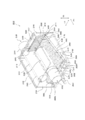
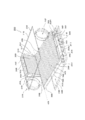
- the front-rear direction FR is a direction perpendicular to the front surface portion 2130 and the back surface portion 2140 of the housing 2100 described later (direction along the arrow FR in FIG. 11).
- the front-rear direction FR is parallel to the top surface portion 2110 and the bottom surface portion 2120, and is also a direction parallel to the right side surface portion 2150 and the left side surface portion 2160.
- the left-right direction LR is a direction perpendicular to the right side surface portion 1150 and the left side surface portion 1160 (direction along the arrow LR in FIG. 1).
- the left-right direction LR is parallel to the top surface portion 1110 and the bottom surface portion 1120, and is also parallel to the front surface portion 1130 and the back surface portion 1140.
- the left-right direction LR is a direction perpendicular to the right side surface portion 2150 and the left side surface portion 2160 (direction along the arrow LR in FIG. 11).
- the left-right direction LR is parallel to the top surface portion 2110 and the bottom surface portion 2120, and is also parallel to the front surface portion 2130 and the back surface portion 2140.
- the vertical direction TB is a direction perpendicular to the top surface portion 1110 and the bottom surface portion 1120 (direction along the arrow TB in FIG. 1).
- the vertical TB is parallel to the front surface portion 1130 and the back surface portion 1140, and is also parallel to the right side surface portion 1150 and the left side surface portion 1160.
- the vertical direction TB is a direction perpendicular to the top surface portion 2110 and the bottom surface portion 2120 (direction along the arrow TB in FIG. 11).
- the vertical direction TB is parallel to the front surface portion 2130 and the back surface portion 2140, and is also a direction parallel to the right side surface portion 2150 and the left side surface portion 2160.
- the longitudinal direction LD is a direction parallel to the direction in which the inlet pipe 1200, the outlet pipe 1300, the inlet pipe 2200, and the outlet pipe 2300, which will be described later, extend.
- the inlet pipe 1200, the outlet pipe 1300, the inlet pipe 2200, and the outlet pipe 2300 have a cylindrical shape
- the longitudinal LD has the inlet pipe 1200, the outlet pipe 1300, the inlet pipe 2200, and the outlet.
- the direction is parallel to the axial direction of the pipe 2300 (the direction along the central axis and the direction along the extending axis).
- the lateral SD is a direction perpendicular to the longitudinal LD.
- the lateral SD is the radial direction (diameter direction) of the inlet pipe 1200, the outlet pipe 1300, the inlet pipe 2200, and the outlet pipe 2300, and may be a direction along any radius (diameter).
- the upper side means a direction toward the top surface portion 1110 or a position close to the top surface portion 1110.
- the lower side means a direction toward the bottom surface portion 1120 and a position close to the bottom surface portion 1120.
- the right side means a direction toward the right side surface portion 1150 and a position close to the right side surface portion 1150.
- the left side means a direction toward the left side surface portion 1160 and a position close to the left side surface portion 1160.
- the front side means a direction toward the front surface portion 1130 or a position close to the front surface portion 1130.
- the rear side refers to a direction toward the back surface portion 1140 and a position close to the back surface portion 1140.
- the gas-liquid separation device according to the first embodiment and the second embodiment is mounted on a vehicle such as various vehicles or ships, and swings due to an impact or vibration generated when the vehicle moves, or on a slope. It may tilt due to the running of the vehicle, and the direction will differ depending on the condition of the vehicle.
- the vertical TB coincides with the vertical VD
- the front-rear FR and the horizontal LR coincide with the horizontal HD.
- the inside is an area inside the housing 1100 and the housing 2100. That is, the inside means an area surrounded by a top surface portion 1110, a bottom surface portion 1120, a front surface portion 1130, a back surface portion 1140, a right surface portion 1150, and a left surface portion 1160, and a top surface portion 2110, a bottom surface portion 2120, a front surface portion 2130, and a back surface. It is an area surrounded by the portion 2140, the right surface portion 2150, and the left surface portion 2160.
- the outside is an area other than the inside of the housing 1100 or the housing 2100 that does not include the housing 1100 or the housing 2100, and is an area that does not include the housing 1100 or the housing 2100 itself.
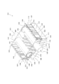
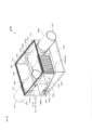
- FIG. 1 is an internal permeation perspective view showing the overall configuration of the gas-liquid separation device 1010 according to the first embodiment.
- FIG. 2 is an internal permeation perspective view showing an outline of the internal configuration of the gas-liquid separation device 1010 according to the first embodiment.
- FIG. 3 is an internal permeation perspective view showing an outline of the internal configuration of the gas-liquid separation device 1010 according to the first embodiment.
- FIG. 4 is an internal permeation perspective view showing an outline of the internal configuration of the gas-liquid separation device 1010 according to the first embodiment.
- FIG. 5 is an internal permeation perspective view showing an outline of the internal configuration of the gas-liquid separation device 1010 according to the first embodiment.
- FIG. 6 is a perspective front view showing an outline of the internal configuration of the gas-liquid separation device 1010 according to the first embodiment.
- FIG. 7 is an internal permeation perspective view showing an outline of the internal configuration of the gas-liquid separation device 1010 according to the first embodiment.
- FIG. 8 is an internal permeation perspective view showing an outline of the internal configuration of the gas-liquid separation device 1010 according to the first embodiment.
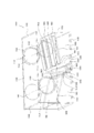
- FIG. 9 shows the right V-shaped groove forming portion 1400, the right inclined V-shaped groove forming portion 1470, the left side V-shaped groove forming portion 1600, and the left side inclined V-shaped groove forming portion 1670 of the gas-liquid separation device 1010 according to the first embodiment. It is sectional drawing which shows the outline of the front V-shaped groove forming part 2400, and the inclined V-shaped groove forming part 2470 of the gas-liquid separation apparatus 2010 by 2nd Embodiment.
- FIG. 10 is a schematic view showing a gas-liquid two-phase flow, a liquid phase, and a gas phase flow in the gas-liquid separation device 1010 according to the first embodiment.
- the gas-liquid separation device 1010 according to the first embodiment mainly includes an inlet pipe 1200, a right V-shaped groove forming portion 1400, a right inclined V-shaped groove forming portion 1470, a left inclined V-shaped groove forming portion 1670, and a left V-shaped portion. It has a groove forming portion 1600 and an outlet pipe 1300.
- the right V-shaped groove forming portion 1400 has a V-shaped groove portion 1402 in cross section
- the right inclined V-shaped groove forming portion 1470 has a V-shaped groove portion 1472 in cross section and is inclined to the left side.
- the V-shaped groove forming portion 1670 has a groove portion 1672 having a V-shaped cross section
- the left V-shaped groove forming portion 1600 has a groove portion 1602 having a V-shaped cross section.
- the gas-liquid two-phase flow sucked from the inlet pipe 1200 is, in order, the groove 1402 of the right V-shaped groove forming portion 1400, the groove 1472 of the right inclined V-shaped groove forming portion 1470, and the groove portion 1672 of the left inclined V-shaped groove forming portion 1670. , It comes into contact with the groove 1602 of the left V-shaped groove forming portion 1600, and is separated into a gas phase and a liquid phase by surface tension. The separated gas phase is discharged from the outlet pipe 1300, and the separated liquid phase is discharged from the drain port 1800.
- the gas-liquid separation device 1010 is a device that separates the gas phase and the liquid phase by the grooves of the four V-shaped groove forming portions in this way.
- the gas-liquid separation device 1010 has a housing 1100.
- the housing 1100 has a substantially square columnar shape.
- the housing 1100 has a top surface portion 1110, a bottom surface portion 1120, a front surface portion 1130, a back surface portion 1140, a right side surface portion 1150, and a left side surface portion 1160.
- the top surface portion 1110, the bottom surface portion 1120, the front surface portion 1130, the back surface portion 1140, the right side surface portion 1150, and the left side surface portion 1160 have a substantially plate-like rectangular shape.
- the housing 1100 has a substantially square columnar shape, and has a substantially square tubular side surface portion and two bottom surface portions facing each other across the side surface portion.
- the side surface portion of the housing 1100 is composed of a top surface portion 1110, a bottom surface portion 1120, a right side surface portion 1150, and a left side surface portion 1160. Further, the bottom surface portion of the housing 1100 is composed of a front surface portion 1130 and a back surface portion 1140.
- the top surface portion 1110, the bottom surface portion 1120, the front surface portion 1130, the back surface portion 1140, the right side surface portion 1150, and the left side surface portion 1160 may be configured separately or integrally. Further, the thicknesses of the top surface portion 1110, the bottom surface portion 1120, the front surface portion 1130, the back surface portion 1140, the right side surface portion 1150, and the left side surface portion 1160 are appropriately determined according to various conditions such as the temperature and pressure inside the housing 1100. be able to.
- the top surface portion 1110 is provided with an airflow control unit 1115 to prevent the gas-liquid two-phase flow from approaching the top surface portion 1110 so that the gas-liquid two-phase flow can be caused by a right-sided inclined V-shaped groove forming portion 1470 or the like.
- the flow of the gas-liquid two-phase flow can be controlled so as to approach the left-side inclined V-shaped groove forming portion 1670.
- the front surface portion 1130 has a front opening 1132 for a suction pipe and a front opening 1134 for a discharge pipe.
- the back surface portion 1140 has a back opening 1142 for a suction pipe and a back opening 1144 for a discharge pipe.
- the front opening 1132 for the suction pipe, the front opening 1134 for the discharge pipe, the back opening 1142 for the suction pipe, and the back opening 1144 for the discharge pipe are through holes having a substantially circular shape.
- the front opening 1132 for the suction pipe and the back opening 1142 for the suction pipe lock or hold the inlet pipe 1200 described later.
- the discharge pipe front opening 1134 and the discharge pipe back opening 1144 lock and hold the outlet pipe 1300 and the inlet pipe 1200, which will be described later. Details will be described in detail later.
- the gas-liquid separation device 1010 has an inlet pipe 1200.
- the inlet pipe 1200 has a constant radius and a long cylindrical shape.
- the cylindrical side surface 1210 of the inlet pipe 1200 has a substantially cylindrical shape.
- the inlet pipe 1200 is arranged perpendicular to the front surface portion 1130 and the back surface portion 1140.
- the inlet pipe 1200 can be arranged parallel to the top surface portion 1110 and the bottom surface portion 1120, and parallel to the right side surface portion 1150 and the left side surface portion 1160.
- the inlet pipe 1200 is arranged through the front opening 1132 for the suction pipe and is held by the front opening 1132 for the suction pipe.
- the inlet pipe 1200 is arranged so that the uppermost portion 1250 of the inlet pipe 1200 is substantially in contact with the inner surface of the top surface portion 1110 from the front portion 1130 to the back portion 1140.
- the uppermost portion 1250 of the inlet pipe 1200 is the uppermost portion of the cylindrical side surface 1210 of the inlet pipe 1200.
- the inlet tube 1200 has a suction opening 1220 and a locking opening 1230.
- the suction opening 1220 and the locking opening 1230 are openings formed at two ends in the longitudinal direction of the inlet pipe 1200, and are through holes having a substantially circular shape.
- the suction opening 1220 is an opening for sucking a gas-liquid two-phase flow and introducing it into the housing 1100.
- the locking opening 1230 is a circular through hole.
- the locking opening 1230 engages with the suction tube back opening 1142 and is sealed by the suction sealer 1146.
- the suction sealing body 1146 has a substantially circular shape and is attached in close contact with the locking opening 1230 to seal the locking opening 1230 of the inlet pipe 1200. Since the locking opening 1230 is sealed by the suction sealing body 1146, the gas-liquid two-phase flow sucked from the suction opening 1220 is not discharged from the locking opening 1230.
- the inlet tube 1200 has a plurality of, eg, 7 discharge openings 1240.
- the seven discharge openings 1240 have a substantially circular shape with the same radius.
- the seven discharge openings 1240 are formed at equal intervals on the cylindrical side surface 1210 of the inlet pipe 1200.
- the seven discharge openings 1240 face the right V-shaped groove forming portion 1400, which will be described later, along the longitudinal direction of the inlet pipe 1200.
- the gas-liquid two-phase flow sucked from the suction opening 1220 is discharged from each of the seven discharge openings 1240 toward the right V-shaped groove forming portion 1400, and the gas-liquid two-phase flow is discharged from the right V-shaped groove forming portion 1400, which will be described later. It comes into contact with the groove portion 1402 of the portion 1400.
- the gas-liquid separation device 1010 has an outlet pipe 1300.
- the outlet pipe 1300 has a constant radius and a long cylindrical shape.
- the cylindrical side surface 1310 of the outlet pipe 1300 has a substantially cylindrical shape.
- the outlet pipe 1300 is arranged perpendicular to the front surface portion 1130 and the back surface portion 1140.
- the outlet pipe 1300 can be arranged parallel to the top surface portion 1110 and the bottom surface portion 1120, and parallel to the right side surface portion 1150 and the left side surface portion 1160.
- the outlet pipe 1300 is arranged through the discharge pipe back opening 1144 and is held by the discharge pipe front opening 1134.
- the outlet pipe 1300 is arranged so that the uppermost portion 1350 of the outlet pipe 1300 is substantially in contact with the inner surface of the top surface portion 1110 from the back portion 1140 to the front portion 1130.
- the uppermost portion 1350 of the outlet pipe 1300 is a portion located on the uppermost side of the cylindrical side surface 1310 of the outlet pipe 1300.
- the outlet pipe 1300 has a discharge opening 1320 and a locking opening 1330.
- the discharge opening 1320 and the locking opening 1330 are openings formed at two ends in the longitudinal direction of the outlet pipe 1300, and are through holes having a substantially circular shape.
- the discharge opening 1320 is an opening for discharging the gas phase and leading it to the outside of the housing 1100. If the gas-liquid separation device 1010 cannot sufficiently separate the gas phase and the liquid phase, it is assumed that the unseparated gas-liquid two-phase flow is discharged from the discharge opening 1320. Further, even when the gas-liquid two-phase flow is separated into the gas phase and the liquid phase, it is assumed that the liquid phase is discharged from the discharge opening 1320.
- the locking opening 1330 is a circular through hole.
- the locking opening 1330 engages with the discharge pipe front opening 1134 and is sealed by the discharge sealer 1136.
- the discharge sealing body 1136 has a substantially circular shape and is attached in close contact with the locking opening 1330 to seal the locking opening 1330 of the outlet pipe 1300. Since the locking opening 1330 is sealed by the discharge sealing body 1136, the gas phase or the gas-liquid two-phase flow is not sucked into the outlet pipe 1300 from the locking opening 1330.
- the outlet pipe 1300 has a plurality of, for example, seven suction openings 1340.
- the seven suction openings 1340 have a substantially circular shape with the same radius.
- the seven suction openings 1340 are formed at equal intervals on the cylindrical side surface 1310 of the outlet pipe 1300.
- the seven suction openings 1340 face the left V-shaped groove forming portion 1600, which will be described later, along the longitudinal direction of the outlet pipe 1300.
- the gas phase is sucked into the outlet pipe 1300 through the seven suction openings 1340, and is led out from the discharge opening 1320 of the outlet pipe 1300 to the outside of the housing 1100.
- Position of inlet pipe 1200 and outlet pipe 1300 By arranging the inlet pipe 1200 and the outlet pipe 1300 as described above, the inlet pipe 1200 and the outlet pipe 1300 are both positioned substantially in contact with the inner surface of the top surface portion 1110 (the same height in the vertical direction TB). And are arranged parallel to each other. That is, the inlet pipe 1200 and the outlet pipe 1300 are arranged at the uppermost positions on the inner surface of the housing 1100.
- Drainage port 1800 is an opening for discharging the liquid phase separated from the gas-liquid two-phase flow to the outside of the housing 1100.
- the drainage port 1800 has a substantially circular shape.
- the drainage port 1800 is formed on the front surface portion 1130 directly above the bottom surface portion 1120.
- a connecting member 1850 for connecting a drain hose (not shown) can be connected to the drain port 1800.
- the drainage guide groove portion 1810 is a groove body for temporarily storing the separated liquid phase and guiding the separated liquid phase to the drainage port 1800.
- the drainage guide groove portion 1810 communicates with the drainage port 1800, stores the liquid phase transmitted through the right side inclined bottom portion 1450 and the left side inclined bottom portion 1650, which will be described later, and guides the liquid phase toward the drainage port 1800.
- the drainage guide groove portion 1810 includes a drainage inclined portion 1820, a drainage right side wall portion 1830, a drainage left side wall portion 1840, and a part of the bottom surface portion 1120.
- the drainage guide groove portion 1810 has a long shape, and is formed by connecting substantially half of the left-right direction LR of the bottom surface portion 1120 along the front-rear direction FR (see the alternate long and short dash line HBO in FIG. 7).
- the drainage inclined portion 1820 has an elongated shape and a flat inclined surface.
- the drainage inclined portion 1820 is formed so as to be inclined so that the back surface portion 1140 is the highest and the drainage inclined portion 1820 is gradually lowered toward the front surface portion 1130.
- the drainage slope 1820 can guide the liquid phase toward the drainage port 1800 formed on the front surface 1130.
- the drainage inclined portion 1820 is a long region sandwiched between the drainage right side wall portion 1830 and the drainage left side wall portion 1840 facing each other.
- ⁇ Drainage right side wall 1830 and drainage left side wall 1840> The drainage right side wall portion 1830 and the drainage left side wall portion 1840 are arranged so as to face each other in parallel with the drainage inclined portion 1820.
- the upper end 1832 of the drainage right side wall 1830 is higher than the upper end 1842 of the drainage left side wall 1840.
- the drainage right side wall portion 1830 has a flat surface and is arranged perpendicular to the bottom surface portion 1120.
- the drainage right wall portion 1830 has an upper end portion 1832 and a lower end portion 1834.
- the upper end 1832 of the drainage right wall 1830 coincides with the lower end 1454 of the right inclined bottom 1450.
- the lower end 1834 of the drainage right wall 1830 coincides with the bottom surface 1120.
- the drainage left side wall portion 1840 has a flat surface and is arranged perpendicular to the bottom surface portion 1120.
- the drainage left wall portion 1840 has an upper end portion 1842 and a lower end portion 1844.
- the upper end 1842 of the drainage left wall 1840 coincides with the lower end 1654 of the left inclined bottom 1650.
- the lower end 1844 of the drainage left wall 1840 coincides with the bottom surface 1120.
- the drainage port 1800 is formed on the front portion 1130, but the drainage port 1800 may be formed on the back portion 1140.
- the liquid phase can be discharged from the back surface portion 1140.
- Right side V-shaped groove forming portion 1400 comes into contact with the gas-liquid two-phase flow discharged from the discharge opening 1240 of the inlet pipe 1200 to separate the liquid phase and the gas phase, and the separated liquid phase is separated into the right inclined bottom portion 1450. I will guide you to.
- the right V-shaped groove forming portion 1400 is a grooved body, and has a plurality of elongated groove portions 1402 having a substantially V-shaped cross section.
- the plurality of grooves 1402 are positioned parallel to each other.
- the right V-shaped groove forming portion 1400 has a long concave portion 1404 (valley) having a substantially V-shaped cross section and a long convex portion 1406 (mountain) having a substantially inverted V-shaped cross section. Part) and are repeatedly formed in parallel with each other.
- the liquid phase component is held in the groove 1402 by the action of surface tension and flows down.
- the gas phase component is separated from the liquid phase component and separated from the groove portion 1402. In this way, the groove 1402 ensures that the gas-liquid two-phase flow is separated into a gas phase and a liquid phase.
- the right V-shaped groove forming portion 1400 has a plurality of groove portions 1402, but has a thin plate-like shape as a whole. That is, the valley bottoms of the recesses 1404 of all the grooves 1402 are located along one plane, and the peaks of the convex portions 1406 of all the grooves 1402 are also along another plane parallel to one plane. Is located.
- the front and back surfaces of the right V-shaped groove forming portion 1400 are formed in the same manner, and the concave portion 1404 (valley portion) on the front surface becomes the convex portion 1406 (mountain portion) on the back surface and the convex portion 1406 (mountain portion) on the front surface. Is a recess 1404 (valley) on the front surface of the back surface. Therefore, the liquid phase and the gas phase can be separated regardless of whether the gas-liquid two-phase flow contacts the front surface of the right V-shaped groove forming portion 1400 or the back surface.
- the right V-shaped groove forming portion 1400 is arranged in the upper half of the right surface portion 1150 facing the right surface portion 1150. That is, by extending the plurality of groove portions 1402 of the right side V-shaped groove forming portion 1400 over the upper half of the right side surface portion 1150 (half of the top surface portion 1110 side), the gas-liquid two-phase flow forms the right V-shaped groove. The region that can come into contact with the portion 1400 can be increased to increase the opportunity for separation into the liquid phase and the gas phase.
- the plurality of groove portions 1402 are arranged so that the longitudinal direction of the plurality of groove portions 1402 is along the vertical direction. That is, the plurality of groove portions 1402 are arranged in the longitudinal direction of the plurality of groove portions 1402 from the top surface portion 1110 toward the bottom surface portion 1120. By doing so, the liquid phase separated by contacting with the plurality of groove portions 1402 is guided downward along the groove portions 1402.
- the right V-shaped groove forming portion 1400 has an upper end portion 1412 and a lower end portion 1414.
- the upper end portion 1412 of the right V-shaped groove forming portion 1400 is located substantially in contact with the inner surface of the top surface portion 1110.
- the lower end portion 1414 of the right side V-shaped groove forming portion 1400 is located substantially in contact with the inner surface of the upper end portion 1456 of the right side inclined bottom portion 1450.
- the right V-groove forming portion 1400 has a front end portion 1416 and a rear end portion 1418.
- the front end 1416 of the right V-groove forming portion 1400 is in contact with the inner surface of the front end 1130, and the rear end 1418 is in contact with the inner surface of the back surface 1140.
- the groove portion 1402 has a substantially V-shaped cross section.
- the groove angle of the groove portion 1402 is preferably less than 90 degrees (acute angle). As shown in FIG. 9A, the groove angle refers to the angle ⁇ formed by two groove surfaces facing each other across the valley bottom of the recess 1404 (valley).
- the number of times the gas-liquid two-phase flow comes into contact with the groove 1402 can be appropriately adjusted depending on the groove angle ⁇ , the depth of the recess 1404 (or the height of the mountain), the position of contact with the groove 1402, and the like. ..
- the right inclined bottom portion 1450 has a flat shape except for the portion of the two ribs 1452 described later.
- the right side inclined bottom portion 1450 is arranged so as to be inclined so as to gradually lower from the right side surface portion 1150 toward the left side surface portion 1160.
- the right-side inclined bottom portion 1450 is inclined so as to form an ⁇ 1 (acute angle) with respect to the horizontal direction.
- the right inclined bottom portion 1450 guides the liquid phase flowing from the right V-shaped groove forming portion 1400 toward the drainage guide groove portion 1810.
- the right inclined bottom portion 1450 has a lower end portion 1454 and an upper end portion 1456.
- the upper end portion 1456 of the right side inclined bottom portion 1450 is positioned at the horizontal central portion HCR (see FIGS. 2 and 5) in which substantially half of the vertical direction TB of the right side surface portion 1150 is connected along the front-rear direction FR.
- the lower end 1454 of the right inclined bottom 1450 is positioned at the upper end 1832 of the drain right wall 1830 of the drain guide groove 1810.
- the right-side inclined bottom portion 1450 extends from the right-side surface portion 1150 to the upper end portion 1832 of the drainage right-side wall portion 1830 of the drainage guide groove portion 1810 while gradually decreasing.
- the right inclined bottom portion 1450 is formed in close contact with the right surface portion 1150.
- the right side inclined bottom portion 1450 may be formed integrally with the right side surface portion 1150 or may be formed separately. By forming in this way, the gas-liquid two-phase flow, the liquid phase, and the gas phase do not leak to the right lower space 1460, which will be described later.
- the right inclined bottom 1450 has a plurality of ribs, for example, two parallel ribs 1452.
- the rib 1452 has a long, thin plate-like shape and is erected on the surface of the right inclined bottom portion 1450.
- the rib 1452 is formed from the right side surface portion 1150 to the upper end portion 1832 of the drainage right side wall portion 1830 of the drainage guide groove portion 1810.
- the rib 1452 contacts the back side of the convex portion 1476 (mountain portion) of the right inclined V-shaped groove forming portion 1470, which will be described later, and supports the right inclined V-shaped groove forming portion 1470.
- Right lower space 1460 is a space surrounded by a bottom surface portion 1120, a front surface portion 1130, a back surface portion 1140, a right side inclined bottom portion 1450, a right side surface portion 1150, and a drainage right side wall portion 1830.
- a device or component such as a heat source in the lower right space 1460, it is possible to prevent the liquid phase from freezing. By doing so, the lower right space 1460 can be effectively utilized.
- Right side inclined V-shaped groove forming portion 1470 contacts the gas-liquid two-phase flow that was not separated by the right-side V-shaped groove forming portion 1400, separates the liquid phase and the gas phase, and separates the separated liquid phase into the drainage guide groove portion. I will guide you to 1810.
- the right-side inclined V-shaped groove forming portion 1470 has a plurality of elongated groove portions 1472 having a substantially V-shaped cross section.
- the plurality of grooves 1472 are positioned parallel to each other.
- the right-side inclined V-shaped groove forming portion 1470 has a long concave portion 1474 (valley portion) having a substantially V-shaped cross section and a long convex portion 1476 (long convex portion) having a substantially inverted V-shaped cross section. Yamabe) is repeatedly formed in parallel with each other.
- the liquid phase component is held by the groove 1472 by the action of surface tension and flows down.
- the gas phase component is separated from the liquid phase component and separated from the groove portion 1472. In this way, the groove portion 1472 ensures that the gas-liquid two-phase flow is separated into a gas phase and a liquid phase.
- the right-side inclined V-shaped groove forming portion 1470 has a plurality of groove portions 1472, but has a thin plate-like shape as a whole. That is, the valley bottoms of the recesses 1474 of all the grooves 1472 are located along one plane, and the peaks of the protrusions 1476 of all the grooves 1472 are also along another plane parallel to one plane. Is located.
- the front and back surfaces of the right-side inclined V-shaped groove forming portion 1470 are formed in the same manner as the right-side V-shaped groove forming portion 1400, and the concave portion 1474 (valley portion) on the front surface is the convex portion 1476 (mountain portion) on the back surface.
- the convex portion 1476 (mountain portion) on the front surface becomes the concave portion 1474 (valley portion) on the front surface of the back surface. Therefore, the liquid phase and the gas phase can be separated regardless of whether the gas-liquid two-phase flow comes into contact with the front surface of the right V-shaped groove forming portion 1470 or the back surface.
- the right inclined V-shaped groove forming portion 1470 is arranged above the right inclined bottom portion 1450, substantially parallel to the right inclined bottom portion 1450, separated from the right inclined bottom portion 1450, and covers the right inclined bottom portion 1450. With this configuration, the right side inclined gap portion 1500 can be formed between the right side inclined V-shaped groove forming portion 1470 and the right side inclined bottom portion 1450. As described above, the right inclined V-groove forming portion 1470 is supported at a fixed position by the two ribs 1452 of the right inclined bottom portion 1450. The right-side inclined V-shaped groove forming portion 1470 inclines at an acute angle of ⁇ 1 with respect to the horizontal direction.
- the right-side inclined V-shaped groove forming portion 1470 is integrally formed with the two ribs 1452, or is fixed to the two ribs 1452 by a fixing tool such as a screw or a locking tool, or the two ribs. It can be fixed by being welded to 1452.
- the right-side inclined V-shaped groove forming portion 1470 may be supported at a fixed position and in a fixed posture.
- the plurality of groove portions 1472 are arranged so that the longitudinal direction of the plurality of groove portions 1472 is parallel to the right inclined bottom portion 1450 and along the left-right direction LR. That is, the plurality of groove portions 1472 are arranged so as to gradually lower toward the left side surface portion 1160.
- the liquid phase separated by the gas-liquid two-phase flow coming into contact with the plurality of groove portions 1472 flows down the groove portion 1472.
- the gas-liquid two-phase flow that was not separated by the right-side inclined V-shaped groove forming portion 1470 is guided to the left-side inclined V-shaped groove forming portion 1670, which will be described later.
- the right side inclined V-shaped groove forming portion 1470 has an upper end portion 1482 and a lower end portion 1484.
- the upper end portion 1482 of the right side inclined V-shaped groove forming portion 1470 is located at a distance from the right side V-shaped groove forming portion 1400. That is, a right gap portion 1550 was formed between the lower end portion 1414 of the right V-shaped groove forming portion 1400 and the upper end portion 1482 of the right side inclined V-shaped groove forming portion 1470. Further, as described above, the right side inclined bottom portion 1450 is formed in close contact with the right side surface portion 1150.
- the liquid phase separated by the right V-shaped groove forming portion 1400 is not guided by the right inclined V-shaped groove forming portion 1470, and is arranged below the right inclined V-shaped groove forming portion 1470. Immediately flow down to the drainage guide groove portion 1810. Further, since the liquid phase from the right V-shaped groove forming portion 1400 is not guided to the right-side inclined V-shaped groove forming portion 1470, the gas-liquid two-phase flow that was not separated by the right-side V-shaped groove forming portion 1400 is inclined to the right. By actively guiding the V-shaped groove forming portion 1470 and bringing it into contact with the groove portion 1472, the liquid phase can be separated at the right-side inclined V-shaped groove forming portion 1470.
- the gas-liquid two-phase flow that was not separated by the right V-shaped groove forming portion 1400 is also guided between the right inclined V-shaped groove forming portion 1470 and the right inclined bottom portion 1450.
- the gas-liquid two-phase flow also contacts the back side of the convex portion 1476 (mountain portion) of the right-side inclined V-shaped groove forming portion 1470, and is separated into the liquid phase and the gas phase in the same manner as the groove portion 1472, and the drainage guide groove portion. It flows down to 1810.
- the lower end portion 1484 of the right side inclined V-shaped groove forming portion 1470 is located above the lower end portion 168 of the left side inclined V-shaped groove forming portion 1670, which will be described later, and covers a part of the left side inclined V-shaped groove forming portion 1670.
- the gas-liquid two-phase flow that was not separated by the right-side inclined V-shaped groove forming portion 1470 can be guided to the left-side inclined V-shaped groove forming portion 1670.
- the liquid phase separated by the right-side inclined V-shaped groove forming portion 1470 is once guided to the lower end portion 1684 of the left-side inclined V-shaped groove forming portion 1670, and then flows down to the drainage guide groove portion 1810.
- the right-sided inclined V-groove forming portion 1470 has a front end portion 1486 and a rear end portion 1488.
- the front end 1486 of the right inclined V-groove forming portion 1470 is in contact with the inner surface of the front surface portion 1130
- the rear end portion 1488 is in contact with the inner surface of the back surface portion 1140.
- the cross-sectional shape of the groove portion 1472 is the same as the cross-sectional shape of the groove portion 1402 (see FIG. 9), and the groove angle of the groove portion 1472 is less than 90 degrees (acute angle). By doing so, the possibility that the gas-liquid two-phase flow comes into contact with the groove portion 1472 more (for example, three times or more) can be increased, and the gas-liquid two-phase flow can be easily separated into the liquid phase and the gas phase. ..
- the number of times the gas-liquid two-phase flow comes into contact with the groove portion 1472 can be appropriately adjusted depending on the groove angle ⁇ , the depth of the recess 1474 (or the height of the mountain), the position of contact with the groove portion 1472, and the like. ..
- the right side gap portion 1550 is formed between the lower end portion 1414 of the right side V-shaped groove forming portion 1400 and the upper end portion 1482 of the right side inclined V-shaped groove forming portion 1470, and the right side inclined V-shaped groove forming portion 1470.
- a right-side inclined gap portion 1500 is formed between the right-side inclined bottom portion 1450 and the right-side inclined bottom portion 1450. Therefore, the gas-liquid two-phase flow that was not separated by the right V-shaped groove forming portion 1400 may enter the right inclined gap portion 1500 via the right gap portion 1550.
- the front and back surfaces of the right-side inclined V-shaped groove forming portion 1470 are formed in the same manner, and the gas-liquid two-phase flow comes into contact with the right-side inclined V-shaped groove forming portion 1470 even on the right-side inclined gap portion 1500 side. Then, the liquid phase and the gas phase can be separated at the right inclined gap portion 1500. Therefore, by separating the gas-liquid two-phase flow into the liquid phase and the gas phase on both the front surface and the back surface of the right-side inclined V-shaped groove forming portion 1470, the liquid phase and the gas phase can be efficiently separated. Can be done.
- the left inclined bottom 1650 has an approximately flat shape.
- the left inclined bottom portion 1650 is arranged so as to be inclined so as to gradually decrease from the left surface portion 1160 toward the right surface portion 1150.
- the left inclined bottom portion 1650 is inclined so as to form an ⁇ 2 (acute angle) with respect to the horizontal direction.
- the left inclined bottom portion 1650 guides the liquid phase flowing from the left V-shaped groove forming portion 1600, which will be described later, toward the drainage guide groove portion 1810.
- the left inclined bottom portion 1650 has a lower end portion 1654 and an upper end portion 1656.
- the upper end portion 1656 of the left inclined bottom portion 1650 is positioned at the horizontal central portion HCL (see FIG. 4) in which substantially half of the vertical TB of the left surface portion 1160 is connected along the front-rear direction FR.
- the lower end 1654 of the left inclined bottom 1650 is located at the upper end 1842 of the drain left wall 1840 of the drain guide groove 1810.
- the left inclined bottom portion 1650 extends from the left surface portion 1160 to the upper end portion 1842 of the drainage left wall portion 1840 of the drainage guide groove portion 1810 while gradually decreasing.
- the left inclined bottom portion 1650 is formed in close contact with the left surface portion 1160.
- the left inclined bottom portion 1650 may be formed integrally with the left surface portion 1160 or may be formed separately.
- the left inclined bottom portion 1650 contacts the back side of the recess 1674 (valley portion) of the left inclined V-shaped groove forming portion 1670, which will be described later, and supports the left inclined V-shaped groove forming portion 1670.
- Left side inclined V-shaped groove forming portion 1670 >>> The left inclined V-shaped groove forming portion 1670 comes into contact with the gas-liquid two-phase flow that was not separated by the right inclined V-shaped groove forming portion 1470, separates the liquid phase and the gas phase, and guides the separated liquid phase to drainage. Guide to the groove 1810.
- the left inclined V-shaped groove forming portion 1670 has a plurality of elongated groove portions 1672 having a substantially V-shaped cross section.
- the plurality of grooves 1672 are positioned parallel to each other.
- the left inclined V-shaped groove forming portion 1670 has a long concave portion 1674 (valley portion) having a substantially V-shaped cross section and a long convex portion 1676 having a substantially inverted V-shaped cross section. Yamabe) is repeatedly formed in parallel with each other.
- the liquid phase component is held by the groove portion 1672 by the action of surface tension and flows down.
- the gas phase component is separated from the liquid phase component and separated from the groove portion 1672. In this way, the groove portion 1672 ensures that the gas-liquid two-phase flow is separated into a gas phase and a liquid phase.
- the left inclined V-shaped groove forming portion 1670 has a plurality of groove portions 1672, but has a thin plate-like shape as a whole. That is, the valley bottoms of the recesses 1674 of all the grooves 1672 are located along one plane, and the peaks of the protrusions 1676 of all the grooves 1472 are also along another plane parallel to one plane. Is located.
- the left side inclined V-shaped groove forming portion 1670 also has the same front and back surfaces as the right side V-shaped groove forming portion 1400, and the concave portion 1674 (valley portion) on the front surface is the convex portion 1676 (mountain portion) on the back surface. ), And the convex portion 1676 (mountain portion) on the front surface becomes the concave portion 1674 (valley portion) on the front surface of the back surface. Therefore, the liquid phase and the gas phase can be separated regardless of whether the gas-liquid two-phase flow comes into contact with the front surface of the left inclined V-shaped groove forming portion 1670 or the back surface.
- the left inclined V-shaped groove forming portion 1670 is arranged above the left inclined bottom portion 1650, substantially parallel to the left inclined bottom portion 1650, separated from the left inclined bottom portion 1650, and covers the left inclined bottom portion 1650. With this configuration, the left side inclined gap portion 1700 can be formed between the left side inclined V-shaped groove forming portion 1670 and the left side inclined bottom portion 1650.
- the left inclined V-groove forming portion 1670 is supported at a fixed position by the left inclined bottom portion 1650.
- the left inclined V-shaped groove forming portion 1670 is integrally formed with the left inclined bottom portion 1650, fixed to the left inclined bottom portion 1650 by a fixing tool such as a screw or a locking tool, or welded to the left inclined bottom portion 1650. It can be fixed by being welded.
- the left inclined V-shaped groove forming portion 1670 may be supported at a fixed position and in a fixed posture.
- the left-side inclined V-shaped groove forming portion 1670 is inclined so as to form an ⁇ 2 (acute angle) with respect to the horizontal direction.
- ⁇ 2 ⁇ 1
- the angles ⁇ 1 and ⁇ 2 can be appropriately changed according to the flow rate of the gas-liquid two-phase flow introduced into the housing 1100 and the like.
- ⁇ 2 ⁇ 1 may be set.
- the left inclined V-shaped groove forming portion 1670 is arranged above the right inclined V-shaped groove forming portion 1470. More specifically, it is preferable that the lower end portion 1684 of the left inclined V-shaped groove forming portion 1670 is arranged above the lower end portion 1484 of the right inclined V-shaped groove forming portion 1470, and ⁇ 2 ⁇ 1.
- the gas-liquid two-phase flow that has entered the right-side inclined gap portion 1500 can be guided to the back side of the left-side inclined V-shaped groove forming portion 1670, and the gas-liquid two-phase flow is sucked into the suction opening 1340. Therefore, it is possible to prevent the gas from being discharged from the discharge opening 1320, and to separate the gas-liquid two-phase flow into the liquid phase and the gas phase on the back side of the left inclined V-shaped groove forming portion 1670.
- the plurality of groove portions 1672 are arranged so that the longitudinal direction of the plurality of groove portions 1672 is parallel to the left inclined bottom portion 1650 and along the left-right direction LR. That is, the plurality of groove portions 1672 are arranged so as to gradually lower toward the right side surface portion 1150.
- the liquid phase separated by the gas-liquid two-phase flow coming into contact with the plurality of groove portions 1672 flows down the groove portion 1672.
- the gas-liquid two-phase flow that was not separated by the right-side inclined V-shaped groove forming portion 1470 is guided by the left-side inclined V-shaped groove forming portion 1670 and comes into contact with the plurality of groove portions 1672.
- the left inclined V-shaped groove forming portion 1670 has an upper end portion 1682 and a lower end portion 1684.
- the upper end portion 1682 of the left inclined V-shaped groove forming portion 1670 is located at a distance from the left V-shaped groove forming portion 1600. That is, a left gap portion 1750 was formed between the lower end portion 1614 of the left V-shaped groove forming portion 1600 and the upper end portion 1682 of the left inclined V-shaped groove forming portion 1670. Further, as described above, the left side inclined bottom portion 1650 is formed in close contact with the left side surface portion 1160.
- the liquid phase separated by the left side V-shaped groove forming portion 1600 is not guided by the left side inclined V-shaped groove forming portion 1670, and is arranged below the left side inclined V-shaped groove forming portion 1670. Immediately flow down to the drainage guide groove portion 1810. Further, since the liquid phase from the left V-shaped groove forming portion 1600 is not guided to the left inclined V-shaped groove forming portion 1670, the gas-liquid two-phase flow that was not separated by the right V-shaped groove forming portion 1400 is inclined to the left side. By actively guiding the V-shaped groove forming portion 1670 and bringing it into contact with the groove portion 1672, the liquid phase can be separated at the left inclined V-shaped groove forming portion 1670. By arranging in this way, the liquid phase separated by the left V-shaped groove forming portion 1600 is immediately guided to the drainage guide groove portion 1810 by the left inclined bottom portion 1650.
- the lower end portion 1648 of the left inclined V-shaped groove forming portion 1670 is located below the lower end portion 1484 of the right inclined V-shaped groove forming portion 1470 described above, and is covered with a part of the right inclined V-shaped groove forming portion 1470.
- the left inclined V-groove forming portion 1670 has a front end portion 1686 and a rear end portion 1688.
- the front end 1686 of the left inclined V-groove forming portion 1670 is in contact with the inner surface of the front surface portion 1130, and the rear end portion 1688 is in contact with the inner surface of the back surface portion 1140.
- the cross-sectional shape of the groove portion 1672 is the same as the cross-sectional shape of the groove portion 1402 (see FIG. 9), and the groove angle of the groove portion 1672 is less than 90 degrees (acute angle). By doing so, the possibility that the gas-liquid two-phase flow comes into contact with the groove portion 1672 more (for example, three times or more) can be increased, and the gas-liquid two-phase flow can be easily separated into the liquid phase and the gas phase. ..
- the number of times the gas-liquid two-phase flow comes into contact with the groove portion 1672 can be appropriately adjusted depending on the groove angle ⁇ , the depth of the recess 1674 (or the height of the mountain), the position of contact with the groove portion 1672, and the like. ..
- the right inclined gap portion 1500 is formed between the right inclined V-shaped groove forming portion 1470 and the right inclined bottom portion 1450, and the left inclined V-shaped groove forming portion 1670 and the left inclined bottom portion 1650 are formed.
- the left inclined gap portion 1700 is formed.
- the gas-liquid two-phase flow that has not been separated in the right-side inclined gap portion 1500 may enter the left-side inclined gap portion 1700.
- the front and back surfaces of the left inclined V-shaped groove forming portion 1670 are formed in the same manner, and the gas-liquid two-phase flow comes into contact with the left inclined V-shaped groove forming portion 1670 even on the left inclined gap portion 1700 side.
- the liquid phase and the gas phase can be separated at the left inclined gap portion 1700. Therefore, by separating the gas-liquid two-phase flow into the liquid phase and the gas phase on both the front surface and the back surface of the left inclined V-shaped groove forming portion 1670, the liquid phase and the gas phase can be efficiently separated. Can be done.
- Left V-shaped groove forming portion 1600 is guided by the gas-liquid two-phase flow that was not separated by the left inclined bottom portion 1650, and comes into contact with the groove portion 1602 of the left V-shaped groove forming portion 1600, and further becomes a liquid phase and a gas phase. And guide the separated liquid phase.
- the left V-shaped groove forming portion 1600 has a plurality of elongated groove portions 1602 having a substantially V-shaped cross section.
- the plurality of grooves 1602 are positioned parallel to each other.
- the left V-shaped groove forming portion 1600 has a long concave portion 1604 (valley) having a substantially V-shaped cross section and a long convex portion 1606 (mountain) having a substantially inverted V-shaped cross section. Part) and are repeatedly formed in parallel with each other.
- the liquid phase component is held by the groove portion 1602 by the action of surface tension and flows down.
- the gas phase component is separated from the liquid phase component and separated from the groove portion 1602. In this way, the groove 1602 ensures that the gas-liquid two-phase flow is separated into a gas phase and a liquid phase.
- the left V-shaped groove forming portion 1600 has a plurality of groove portions 1602, but has a thin plate-like shape as a whole. That is, the valley bottoms of the recesses 1604 of all the grooves 1602 are located along one plane, and the peaks of the protrusions 1606 of all the grooves 1602 are also along another plane parallel to one plane. Is located.
- the left side V-shaped groove forming portion 1600 also has the same front and back surfaces as the right side V-shaped groove forming portion 1400, and the concave portion 1604 (valley portion) on the front surface is the convex portion 1606 (mountain portion) on the back surface.
- the convex portion 1606 (peak portion) on the front surface becomes the concave portion 1604 (valley portion) on the front surface of the back surface. Therefore, the liquid phase and the gas phase can be separated regardless of whether the gas-liquid two-phase flow comes into contact with the front surface of the left V-shaped groove forming portion 1600 or the back surface.
- the left V-shaped groove forming portion 1600 is arranged so as to face the left surface portion 1160 and occupy the upper half portion of the left surface portion 1160. That is, by arranging over the upper half of the left side surface portion 1160 (half of the top surface portion 1110 side), the area where the gas-liquid two-phase flow comes into contact with the left side V-shaped groove forming portion 1600 can be increased, and the liquid phase can be increased. And the gas phase can be separated.
- the longitudinal direction of the plurality of groove portions 1602 is arranged along the vertical direction. That is, the plurality of groove portions 1602 are arranged from the top surface portion 1110 toward the bottom surface portion 1120. By doing so, the liquid phase separated in contact with the plurality of groove portions 1602 is guided downward along the groove portions 1602.
- the left V-shaped groove forming portion 1600 has an upper end portion 1612 and a lower end portion 1614.
- the upper end portion 1612 of the left V-shaped groove forming portion 1600 is located substantially in contact with the inner surface of the top surface portion 1110. Further, the lower end portion 1614 of the left V-shaped groove forming portion 1600 is located at the upper end portion 1656 of the right inclined bottom portion 1450.
- the left V-groove forming portion 1600 has a front end portion 1616 and a rear end portion 1618.
- the front end 1616 of the left V-groove forming portion 1600 is in contact with the inner surface of the front end 1130, and the rear end 1618 is in contact with the inner surface of the back surface 1140.
- the cross-sectional shape of the groove portion 1602 is the same as the cross-sectional shape of the groove portion 1402 (see FIG. 9), and the groove angle of the groove portion 1602 is less than 90 degrees (acute angle). By doing so, the possibility that the gas-liquid two-phase flow comes into contact with the groove portion 1602 more (for example, three times or more) can be increased, and the liquid phase and the gas phase can be easily separated.
- the number of times the gas-liquid two-phase flow comes into contact with the groove portion 1602 can be appropriately adjusted depending on the groove angle ⁇ , the depth of the recess 1604 (or the height of the mountain), the position of contact with the groove portion 1602, and the like. ..
- the left lower space 1660 is a space surrounded by a bottom surface portion 1120, a front surface portion 1130, a back surface portion 1140, a left side inclined bottom portion 1650, a left side surface portion 1160, and a drainage left side wall portion 1840.
- a device or component such as a heat source in the lower left space 1660, it is possible to prevent the liquid phase from freezing. By doing so, the left lower space 1660 can be effectively utilized.
- a right side gap portion 1550 is formed between the lower end portion 1414 of the right side V-shaped groove forming portion 1400 and the upper end portion 1482 of the right side inclined V-shaped groove forming portion 1470, and the right side V-shaped groove forming portion 1450 is formed.
- the liquid phase flowing through the forming portion 1400 is immediately guided to the right inclined bottom portion 1450 without being guided by the right inclined V-shaped groove forming portion 1470.
- Gas-liquid separation by the left inclined V-shaped groove forming portion 1670 >> The gas-liquid two-phase flow not separated by the right inclined V-shaped groove forming portion 1470 (white arrow TP3 in FIG. 10) is guided to the left inclined V-shaped groove forming portion 1670 (white arrow TP4 in FIG. 10). ..
- the gas-liquid two-phase flow comes into contact with the groove portion 1672 of the left inclined V-shaped groove forming portion 1670, and is separated into a gas phase and a liquid phase by surface tension.
- the liquid phase flows through the left inclined V-shaped groove forming portion 1670 (black arrow LP7 in FIG. 10), flows down from the lower end portion 1684, and is guided toward the drainage guide groove portion 1810 (black arrow LP6 in FIG. 10). ).
- the lower end portion 1484 of the right inclined V-shaped groove forming portion 1470 is located above the lower end portion 168 of the left inclined V-shaped groove forming portion 1670 described later, and is a part of the left inclined V-shaped groove forming portion 1670. (See FIGS. 6 and 10).
- the flow of the gas-liquid two-phase flow that was not separated by the right-side inclined V-shaped groove forming portion 1470 can be positively guided directly above the left-side inclined V-shaped groove forming portion 1670.
- the gas-liquid two-phase flow can be easily brought into contact with the left-side inclined V-shaped groove forming portion 1670.
- Gas-liquid separation by the left V-shaped groove forming portion 1600 >> The gas-liquid two-phase flow not separated by the left inclined V-shaped groove forming portion 1670 is guided to the left V-shaped groove forming portion 1600 (white arrow TP5 in FIG. 10).
- the gas-liquid two-phase flow comes into contact with the groove portion 1602 of the left V-shaped groove forming portion 1600 and is separated into a gas phase and a liquid phase by surface tension.
- the liquid phase flows through the left V-shaped groove forming portion 1600 (black arrow LP8 in FIG. 10), flows through the left inclined bottom portion 1650 (black arrow LP9 in FIG. 10), flows down from the lower end portion 1684, and drains from the drainage guide groove portion.
- a left gap portion 1750 is formed between the lower end portion 1614 of the left V-shaped groove forming portion 1600 and the upper end portion 1682 of the left inclined V-shaped groove forming portion 1670, and flows through the left V-shaped groove forming portion 1600.
- the liquid phase is immediately guided to the left inclined bottom portion 1650 without being guided to the left inclined V-shaped groove forming portion 1670.
- the liquid phase separated by the right V-shaped groove forming portion 1400 flows through the right V-shaped groove forming portion 1400 (black arrow LP1 in FIG. 10) and is guided by the right inclined bottom portion 1450 (FIG. 10).
- the black arrow LP2) is guided toward the drainage guide groove portion 1810.
- the liquid phase separated by the right inclined V-shaped groove forming portion 1470 (black arrow LP4 in FIG. 10) flows through the right inclined V-shaped groove forming portion 1470 and passes through the left inclined V-shaped groove forming portion 1670 (FIG. 10).
- the black arrow LP5) is guided toward the drainage guide groove portion 1810 (black arrow LP6 in FIG. 10).
- the liquid phase separated by the left inclined V-shaped groove forming portion 1670 flows through the left inclined V-shaped groove forming portion 1670 (black arrow LP7 in FIG. 10) and is guided toward the drainage guide groove portion 1810.
- the liquid phase separated by the left V-shaped groove forming portion 1600 flows through the left inclined bottom portion 1650 (black arrow LP9 in FIG. 10) and is guided toward the drainage guide groove portion 1810. (Black arrow LP6 in FIG. 10). All of the liquid phases separated in this way are guided by the drainage guide groove portion 1810 and discharged from the drainage port 1800.
- the drainage guide groove portion 1810 is formed in the central region of the left-right direction LR of the bottom surface portion 1120.
- the right-side inclined bottom portion 1450 and the right-side inclined V-shaped groove forming portion 1470 are arranged so that the right side surface portion 1150 is the highest and gradually decreases toward the central region of the left-right direction LR.
- the left side inclined bottom portion 1650 and the left side inclined V-shaped groove forming portion 1670 are arranged so that the left side surface portion 1160 is the highest and gradually decreases toward the central region of the left-right direction LR. Therefore, the separated liquid phase easily flows toward the central region of the LR in the left-right direction, and flows down toward the drainage guide groove portion 1810.
- the gas-liquid separation device 1010 when the gas-liquid separation device 1010 is mounted on a vehicle such as a vehicle, the gas-liquid separation device 1010 may tilt, vibrate, or receive an impact in the left-right direction LR when passing through a curve. .. Even in such a case, one of the liquid phase from the right inclined bottom portion 1450 and the right inclined V-shaped groove forming portion 1470 and the liquid phase from the left inclined bottom portion 1650 and the left inclined V-shaped groove forming portion 1670. Can be guided to the drainage guide groove portion 1810 and discharged from the gas-liquid separation device 1010.
- the airflow control unit 1115 is provided on the top surface portion 1110 so that the gas-liquid two-phase flow, the gas phase, and the liquid phase do not approach the top surface portion 1110. Therefore, it can be positively guided to the right side inclined V-shaped groove forming portion 1470 and the left side inclined V-shaped groove forming portion 1670.
- the airflow control unit 1115 can increase the chances of separating the gas-liquid two-phase flow into a gas phase and a liquid phase at the right-side inclined V-shaped groove forming portion 1470 and the left-side inclined V-shaped groove forming portion 1670.
- FIG. 11 is an internal permeation perspective view showing the overall configuration of the gas-liquid separation device 2010 according to the second embodiment.
- FIG. 12 is an internal permeation perspective view showing the overall configuration of the gas-liquid separation device 2010 according to the second embodiment.
- FIG. 13 is an internal permeation perspective view showing the overall configuration of the gas-liquid separation device 2010 according to the second embodiment.
- FIG. 14 is an internal permeation plan view showing the overall configuration of the gas-liquid separation device 2010 according to the second embodiment.
- FIG. 15 is an internal permeation right side view showing the overall configuration of the gas-liquid separation device 2010 according to the second embodiment.
- FIG. 16 is an internal permeation left side view showing the overall configuration of the gas-liquid separation device 2010 according to the second embodiment.
- the gas-liquid separation device 2010 according to the second embodiment mainly has an inlet pipe 2200, a front V-shaped groove forming portion 2400, an inclined V-shaped groove forming portion 2470, and an outlet pipe 2300.
- the front V-shaped groove forming portion 2400 has a groove portion 2402 having a V-shaped cross section
- the inclined V-shaped groove forming portion 2470 has a groove portion 2472 having a V-shaped cross section.
- the gas-liquid two-phase flow sucked from the inlet pipe 2200 contacts the groove portion 2402 of the front V-shaped groove forming portion 2400 and the groove portion 2472 of the inclined V-shaped groove forming portion 2470 in order, and the gas phase and the liquid phase are brought into contact with each other by surface tension. Separate into and. The separated gas phase is discharged from the outlet pipe 2300, and the separated liquid phase is discharged from the drain port 2800.
- the gas-liquid separation device 2010 is a device that separates the gas phase and the liquid phase by the grooves of the two V-shaped groove forming portions in this way.
- the gas-liquid separation device 2010 has a housing 2100.
- the housing 2100 has a substantially square columnar shape.
- the housing 2100 has a top surface portion 2110, a bottom surface portion 2120, a front surface portion 2130, a back surface portion 2140, a right side surface portion 2150, and a left side surface portion 2160.
- the top surface portion 2110, the bottom surface portion 2120, the front surface portion 2130, the back surface portion 2140, the right side surface portion 2150, and the left side surface portion 2160 have a substantially plate-like rectangular shape.
- the housing 2100 has a substantially square columnar shape, and has a substantially square tubular side surface portion and two bottom surface portions facing each other across the side surface portion.
- the side surface portion of the housing 2100 is composed of a top surface portion 2110, a bottom surface portion 2120, a right side surface portion 2150, and a left side surface portion 2160. Further, the bottom surface portion of the housing 2100 is composed of a front surface portion 2130 and a back surface portion 2140.
- the top surface portion 2110, the bottom surface portion 2120, the front surface portion 2130, the back surface portion 2140, the right side surface portion 2150, and the left side surface portion 2160 may be configured separately or integrally. Further, the thicknesses of the top surface portion 2110, the bottom surface portion 2120, the front surface portion 2130, the back surface portion 2140, the right side surface portion 2150, and the left side surface portion 2160 are appropriately determined according to various conditions such as the temperature and pressure inside the housing 2100. be able to.
- the front surface portion 2130 has a front opening 2132 for a suction pipe.
- the back surface portion 2140 has a back surface opening 2144 for a discharge pipe.
- the front opening 2132 for the suction pipe and the back opening 2144 for the discharge pipe are through holes having a circular shape.
- the front opening 2132 for the suction pipe locks and holds the inlet pipe 2200 described later.
- the discharge pipe back opening 2144 locks and holds the outlet pipe 2300 described later. Details will be described in detail later.
- the gas-liquid separation device 2010 has an inlet pipe 2200.
- the inlet pipe 2200 has a constant radius and a long cylindrical shape.
- the cylindrical side surface 2210 of the inlet pipe 2200 has a substantially cylindrical shape.
- the inlet pipe 2200 is arranged perpendicular to the front surface portion 2130 and the back surface portion 2140.
- the inlet pipe 2200 can be arranged parallel to the top surface portion 2110 and the bottom surface portion 2120, and parallel to the right side surface portion 2150 and the left side surface portion 2160.
- the inlet pipe 2200 is arranged so as to penetrate the front opening 2132 for the suction pipe and is held by the front opening 2132 for the suction pipe.
- the inlet pipe 2200 is arranged so that the uppermost portion 2250 of the inlet pipe 2200 is substantially in contact with the inner surface of the top surface portion 2110 from the front portion 2130 to the back portion 2140.
- the uppermost portion 2250 of the inlet pipe 2200 is a portion located on the uppermost side of the cylindrical side surface 2210 of the inlet pipe 2200.
- the inlet tube 2200 has a suction opening 2220 and a discharge opening 2240.
- the suction opening 2220 and the discharge opening 2240 are openings formed at two ends in the longitudinal direction of the inlet pipe 2200, and are through holes having a substantially circular shape.
- the suction opening 2220 is an opening for sucking a gas-liquid two-phase flow and introducing it into the housing 2100.
- the discharge opening 2240 is a circular through hole.
- the discharge opening 2240 faces the front V-shaped groove forming portion 2400, which will be described later.
- the gas-liquid two-phase flow sucked from the suction opening 2220 is discharged from the discharge opening 2240 toward the front V-shaped groove forming portion 2400, and the gas-liquid two-phase flow is discharged from the groove portion 2402 of the front V-shaped groove forming portion 2400 described later. Contact with.
- the gas-liquid separation device 2010 has an outlet pipe 2300.
- the outlet pipe 2300 has a constant radius and a long cylindrical shape.
- the cylindrical side surface 2310 of the outlet pipe 2300 has a substantially cylindrical shape.
- the outlet pipe 2300 is arranged perpendicular to the front surface portion 2130 and the back surface portion 2140.
- the outlet pipe 2300 can be arranged parallel to the top surface portion 2110 and the bottom surface portion 2120, and parallel to the right side surface portion 2150 and the left side surface portion 2160.
- the outlet pipe 2300 is arranged so as to penetrate the back opening 2144 for the discharge pipe and is held by the back opening 2144 for the discharge pipe.
- the outlet pipe 2300 is arranged so that the uppermost portion 2350 of the outlet pipe 2300 is substantially in contact with the inner surface of the top surface portion 2110 from the back surface portion 2140 to the front surface portion 2130.
- the uppermost portion 2350 of the outlet pipe 2300 is a portion located on the uppermost side of the inner surface of the cylindrical side surface 2310 of the outlet pipe 2300.
- the outlet pipe 2300 has a discharge opening 2320 and a suction opening 2340.
- the discharge opening 2320 and the suction opening 2340 are openings formed at two ends in the longitudinal direction of the outlet pipe 2300, and are through holes having a substantially circular shape.
- the discharge opening 2320 is an opening for discharging the gas phase and leading it to the outside of the housing 2100. If the gas-liquid separation device 2010 cannot sufficiently separate the gas phase and the liquid phase, it is assumed that the unseparated gas-liquid two-phase flow is discharged from the discharge opening 2320.
- the suction opening 2340 is a circular through hole. The gas phase is sucked into the outlet pipe 2300 from the suction opening 2340 and led out from the discharge opening 2320 of the outlet pipe 2300 to the outside of the housing 2100.
- Position of inlet pipe 2200 and outlet pipe 2300 By arranging the inlet pipe 2200 and the outlet pipe 2300 as described above, the inlet pipe 2200 and the outlet pipe 2300 are both located at positions in contact with the inner surface of the top surface portion 2110 (the same height in the vertical direction TB). And they are arranged parallel to each other. That is, the inlet pipe 2200 and the outlet pipe 2300 are arranged at the uppermost positions on the inner surface of the housing 2100.
- Drainage port 2800 is an opening for discharging the liquid phase separated from the gas-liquid two-phase flow to the outside of the housing 2100.
- the drainage port 2800 has a substantially circular shape.
- the drainage port 2800 is formed on the front surface portion 2130 directly above the bottom surface portion 2120.
- a connecting member 2850 for connecting a drain hose (not shown) can be connected to the drain port 2800.
- the drainage guide groove portion 2810 is a groove body for temporarily storing the separated liquid phase and guiding the separated liquid phase to the drainage port 2800.
- the drainage guide groove portion 2810 communicates with the drainage port 2800, stores the liquid phase transmitted through the inclined bottom portion 2450 described later, and guides the liquid phase toward the drainage port 2800.
- the drainage guide groove portion 2810 includes a right drainage inclined portion 2820R, a left drainage inclined portion 2820L, a drainage front portion 2836, and a part of the bottom surface portion 2120.
- the drainage guide groove portion 2810 has a long shape along the LR in the left-right direction, and is formed on the bottom surface portion 2120 substantially in contact with the inner surface of the front surface portion 2130.
- the right drainage inclined portion 2820R and the left drainage inclined portion 2820L have a long shape and a flat inclined surface.
- the right drainage inclined portion 2820R is formed so as to have the highest right side surface portion 2150 and gradually decrease toward the drainage port 2800.
- the left drainage inclined portion 2820L is formed so as to be inclined so that the left side surface portion 2160 is the highest and gradually decreases toward the drainage port 2800.
- the right drainage inclined portion 2820R and the left drainage inclined portion 2820L can guide the liquid phase toward the drainage port 2800 formed in the front surface portion 2130.
- the drainage port 2800 is formed on the front portion 2130, but the drainage port 2800 may be formed on the back portion 2140.
- the liquid phase can be discharged from the back surface portion 2140.
- the back inclined portion 2430 has a substantially flat shape.
- the back surface inclined portion 2430 has an acute angle ⁇ 3 (see FIG. 15) with respect to the back surface portion 2140, and is formed so as to gradually approach the back surface portion 2110 toward the back surface portion 2140.
- a front V-shaped groove forming portion 2400 which will be described later, is arranged on the back inclined portion 2430.
- Front V-shaped groove forming portion 2400 comes into contact with the gas-liquid two-phase flow discharged from the discharge opening 2240 of the inlet pipe 2200 to separate the liquid phase and the gas phase, and the separated liquid phase is transferred to the inclined bottom 2450. invite.
- the front V-shaped groove forming portion 2400 is a grooved body, and has a plurality of elongated groove portions 2402 having a substantially V-shaped cross section.
- the plurality of grooves 2402 are positioned parallel to each other.
- the front V-shaped groove forming portion 2400 has a long concave portion 2404 (valley) having a substantially V-shaped cross section and a long convex portion 2406 (mountain) having a substantially inverted V-shaped cross section. Part) and are repeatedly formed in parallel with each other.
- the liquid phase component is held by the groove 2402 by the action of surface tension and flows down.
- the gas phase component is separated from the liquid phase component and separated from the groove portion 2402. In this way, the groove 2402 ensures that the gas-liquid two-phase flow is separated into a gas phase and a liquid phase.
- the front V-shaped groove forming portion 2400 has a plurality of groove portions 2402, but has a thin plate-like shape as a whole. That is, the valley bottoms of the recesses 2404 of all the grooves 2402 are located along one plane, and the peaks of the convex portions 2406 of all the grooves 2402 are also along another plane parallel to one plane. Is located.
- the front and back surfaces of the front V-shaped groove forming portion 2400 are formed in the same manner, and the concave portion 2404 (valley portion) on the front surface becomes the convex portion 2406 (mountain portion) on the back surface and the convex portion 2406 (mountain portion) on the front surface. Is a recess 2404 (valley) on the front surface of the back surface. Therefore, the liquid phase and the gas phase can be separated regardless of whether the gas-liquid two-phase flow comes into contact with the front surface of the front V-shaped groove forming portion 2400 or the back surface.
- the front V-shaped groove forming portion 2400 is arranged on the back inclined portion 2430.
- the back inclined portion 2430 is formed on the upper half (half on the top surface portion 2110 side) of the back surface portion 2140. Therefore, the plurality of groove portions 2402 of the front V-shaped groove forming portion 2400 can be extended over the upper half (half of the top surface portion 2110 side) of the back surface portion 2140, and the gas-liquid two-phase flow is front V-shaped.
- the region that can come into contact with the groove forming portion 2400 can be increased to increase the chance that the liquid phase and the gas phase can be separated.
- the front V-shaped groove forming portion 2400 is arranged on the back inclined portion 2430. That is, in the plurality of groove portions 2402, the longitudinal direction of the plurality of groove portions 2402 is arranged along the back surface inclined portion 2430. By doing so, the liquid phase separated in contact with the plurality of groove portions 2402 is guided downward along the groove portions 2402.
- the front V-shaped groove forming portion 2400 has an upper end portion 2412 and a lower end portion 2414.
- the upper end portion 2412 of the front V-shaped groove forming portion 2400 is located substantially in contact with the inner surface of the top surface portion 2110.
- the lower end portion 2414 of the front V-shaped groove forming portion 2400 is located substantially in contact with the inner surface of the upper end portion 2456 of the inclined bottom portion 2450.
- the front V-shaped groove forming portion 2400 has a right end portion 2416 and a left end portion 2418.
- the right end 2416 of the front V-shaped groove forming portion 2400 is in contact with the inner surface of the right side surface portion 2150, and the left end portion 2418 is located near the right side of the cylindrical side surface 2310 of the outlet pipe 2300.
- the gas-liquid two-phase flow can come into contact with the front V-shaped groove forming portion 2400.
- the region can be enlarged to increase the chance of separation between the liquid phase and the gas phase.
- the groove portion 2402 has a substantially V-shaped cross section.
- the groove angle of the groove portion 2402 is preferably less than 90 degrees (acute angle). As shown in FIG. 9A, the groove angle refers to the angle ⁇ formed by two groove surfaces facing each other across the valley bottom of the recess 2404 (valley).
- the number of times the gas-liquid two-phase flow comes into contact with the groove portion 2402 can be appropriately adjusted depending on the groove angle ⁇ , the depth of the recess 2404 (or the height of the mountain), the position of contact with the groove portion 2402, and the like. ..
- the front V-shaped groove forming portion 2400 alone cannot sufficiently separate the liquid phase and the gas phase.
- the front V-shaped groove forming portion 2400 is arranged on the back surface inclined portion 2430, and the back surface inclined portion 2430 is arranged at an acute angle ⁇ 3 with respect to the back surface portion 2140. Therefore, the gas-liquid two-phase flow that is not separated by the front V-shaped groove forming portion 2400 is reflected by the front V-shaped groove forming portion 2400 and guided toward the inclined V-shaped groove forming portion 2470 described later.
- the liquid phase and the gas phase can be separated.
- the inclined bottom 2450 has a substantially flat shape.
- the inclined bottom portion 2450 has an acute angle ⁇ 4 (see FIGS. 15 and 16) with respect to the horizontal direction, and the inclined bottom portion 2450 is arranged so as to gradually decrease from the back surface portion 2140 toward the front surface portion 2130.
- the inclined bottom portion 2450 guides the liquid phase flowing from the front V-shaped groove forming portion 2400 toward the drainage guide groove portion 2810.
- the inclined bottom portion 2450 has a lower end portion 2454 and an upper end portion 2456.
- the upper end portion 2456 of the inclined bottom portion 2450 is positioned at the horizontal central portion HCB (see FIG. 11) in which substantially half of the vertical TB of the back surface portion 2140 is connected along the horizontal LR.
- the lower end 2454 of the inclined bottom 2450 coincides with the upper end 2832 of the drainage guide groove 2810. In this way, the inclined bottom portion 2450 extends from the back surface portion 2140 to the upper end portion 2832 of the drainage guide groove portion 2810 while gradually decreasing.
- the inclined bottom portion 2450 is formed in close contact with the right side surface portion 2150.
- the inclined bottom portion 2450 may be formed integrally with the right side surface portion 2150 or may be formed separately.
- the inclined bottom 2450 has a plurality of, for example, three parallel ribs 2452.
- the rib 2452 has a long and thin plate-like shape, and is erected on the surface of the inclined bottom portion 2450.
- the rib 2452 is formed from the right side surface portion 2150 to the upper end portion 2832 of the drainage guide groove portion 2810.
- the rib 2452 contacts the back side of the convex portion 2476 (mountain portion) of the inclined V-shaped groove forming portion 2470 to be described later, and supports the inclined V-shaped groove forming portion 2470.
- Lower space 2460 is a space surrounded by a bottom surface portion 2120, a drainage front surface portion 2836, a back surface portion 2140, an inclined bottom portion 2450, a right side surface portion 2150, and a left side surface portion 2160.
- a device or component such as a heat source in the lower space 2460, it is possible to prevent the liquid phase from freezing. By doing so, the lower space 2460 can be effectively utilized.
- Inclined V-shaped groove forming portion 2470 contacts the gas-liquid two-phase flow that was not separated by the front V-shaped groove forming portion 2400, separates the liquid phase and the gas phase, and separates the separated liquid phase into the drainage guide groove portion 2810. I will guide you to.
- the inclined V-shaped groove forming portion 2470 has a plurality of elongated groove portions 2472 having a substantially V-shaped cross section.
- the plurality of grooves 2472 are positioned parallel to each other.
- the inclined V-shaped groove forming portion 2470 has a long recess 2474 (valley) having a substantially V-shaped cross section and a long convex portion 2476 (mountain) having a substantially inverted V-shaped cross section. Part) and are repeatedly formed in parallel with each other.
- the liquid phase component is held by the groove portion 2472 by the action of surface tension and flows down.
- the gas phase component is separated from the liquid phase component and separated from the groove portion 2472. In this way, the groove portion 2472 ensures that the gas-liquid two-phase flow is separated into a gas phase and a liquid phase.
- the inclined V-shaped groove forming portion 2470 has a plurality of groove portions 2472, but has a thin plate-like shape as a whole. That is, the valley bottoms of the recesses 2474 of all the grooves 2472 are located along one plane, and the peaks of the protrusions 2476 of all the grooves 2472 are also along another plane parallel to one plane. Is located.
- the inclined V-shaped groove forming portion 2470 also has the same front and back surfaces, and the concave portion 2474 (valley portion) on the front surface becomes the convex portion 2476 (mountain portion) on the back surface.
- the convex portion 2476 (mountain portion) on the front surface becomes the concave portion 2474 (valley portion) on the front surface on the back surface. Therefore, the liquid phase and the gas phase can be separated regardless of whether the gas-liquid two-phase flow comes into contact with the front surface of the inclined V-shaped groove forming portion 2470 or the back surface.
- the inclined V-shaped groove forming portion 2470 is arranged above the inclined bottom portion 2450, substantially parallel to the inclined bottom portion 2450, separated from the inclined bottom portion 2450, and covers the inclined bottom portion 2450. With this configuration, an inclined gap portion 2500 can be formed between the inclined V-shaped groove forming portion 2470 and the inclined bottom portion 2450. As described above, the inclined V-groove forming portion 2470 is supported at a fixed position by the three ribs 2452 of the inclined bottom portion 2450.
- the inclined V-shaped groove forming portion 2470 is integrally formed with the three ribs 2452, or is fixed to the three ribs 2452 by a fixing tool such as a screw or a locking tool, or the three ribs 2452. It can be fixed by being welded to.
- the inclined V-shaped groove forming portion 2470 may be supported at a fixed position and in a fixed posture.
- the plurality of groove portions 2472 are arranged so that the longitudinal direction of the plurality of groove portions 2472 is parallel to the inclined bottom portion 2450 and along the left-right direction LR. That is, the plurality of groove portions 2472 are arranged so as to gradually lower toward the drainage front portion 2836. The liquid phase separated by the gas-liquid two-phase flow coming into contact with the plurality of groove portions 2472 flows down the groove portion 2472.
- the inclined V-shaped groove forming portion 2470 has an upper end portion 2482 and a lower end portion 2484.
- the upper end portion 2482 of the inclined V-shaped groove forming portion 2470 is located at a distance from the front V-shaped groove forming portion 2400. That is, a gap portion 2550 was formed between the lower end portion 2414 of the front V-shaped groove forming portion 2400 and the upper end portion 2482 of the inclined V-shaped groove forming portion 2470. Further, as described above, the inclined bottom portion 2450 is formed in close contact with the right side surface portion 2150.
- the liquid phase separated by the front V-shaped groove forming portion 2400 is not guided by the inclined V-shaped groove forming portion 2470, but is guided by the inclined bottom portion 2450 arranged below the inclined V-shaped groove forming portion 2470. Then, it immediately flows down into the drainage guide groove 2810. Further, since the liquid phase from the front V-shaped groove forming portion 2400 is not guided to the inclined V-shaped groove forming portion 2470, the gas-liquid two-phase flow that was not separated by the front V-shaped groove forming portion 2400 is separated by the inclined V-shaped groove forming portion 2400. By actively guiding the groove forming portion 2470 and bringing it into contact with the groove portion 2472, the inclined V-shaped groove forming portion 2470 can separate the liquid phase.
- the gas-liquid two-phase flow that was not separated by the front V-shaped groove forming portion 2400 is also guided between the inclined V-shaped groove forming portion 2470 and the inclined bottom portion 2450.
- the gas-liquid two-phase flow also contacts the back side of the convex portion 2476 (mountain portion) of the inclined V-shaped groove forming portion 2470, and is separated into the liquid phase and the gas phase in the same manner as the groove portion 2472, and the drainage guide groove portion 2810. Flow down to.
- liquid phase separated by the inclined V-shaped groove forming portion 2470 is once guided by the lower end portion 2484 and flows down to the drainage guide groove portion 2810.
- the inclined V-shaped groove forming portion 2470 has a right end portion 2486 and a left end portion 2488.
- the right end portion 2486 of the inclined V-shaped groove forming portion 2470 is in contact with the inner surface of the right side surface portion 2150
- the left end portion 2488 is in contact with the inner surface of the left side surface portion 2160.
- the cross-sectional shape of the groove portion 2472 is the same as the cross-sectional shape of the groove portion 2402 (see FIG. 9), and the groove angle of the groove portion 2472 is less than 90 degrees (acute angle). By doing so, the possibility that the gas-liquid two-phase flow comes into contact with the groove portion 2472 more (for example, three times or more) can be increased, and the gas-liquid two-phase flow can be easily separated into the liquid phase and the gas phase. ..
- the number of times the gas-liquid two-phase flow comes into contact with the groove portion 2472 can be appropriately adjusted depending on the groove angle ⁇ , the depth of the recess 2474 (or the height of the mountain), the position of contact with the groove portion 2472, and the like. ..
- a gap portion 2550 is formed between the lower end portion 2414 of the front V-shaped groove forming portion 2400 and the upper end portion 2482 of the inclined V-shaped groove forming portion 2470, and the inclined V-shaped groove forming portion 2470 and the inclined bottom portion are formed.
- An inclined gap portion 2500 is formed between the vehicle and the 2450. Therefore, the gas-liquid two-phase flow that has not been separated by the front V-shaped groove forming portion 2400 may enter the inclined gap portion 2500 via the gap portion 2550.
- the front and back surfaces of the inclined V-shaped groove forming portion 2470 are formed to be the same, and even on the inclined gap portion 2500 side, the gas-liquid two-phase flow comes into contact with the inclined V-shaped groove forming portion 2470, so that the inclined V-shaped groove forming portion 2470 is inclined.
- the liquid phase and the gas phase can be separated at the gap portion 2500. Therefore, by separating the gas-liquid two-phase flow into the liquid phase and the gas phase on both the front surface and the back surface of the inclined V-shaped groove forming portion 2470, it is possible to efficiently separate the gas-liquid phase into the gas phase. it can.
- Gas-liquid separation by the front V-shaped groove forming portion 2400 >>> ⁇ Gas-liquid separation by the front V-shaped groove forming portion 2400 >> The gas-liquid two-phase flow (white arrow TP20 in FIGS. 14, 15, and 16) sucked from the inlet pipe 2200 is discharged from the discharge opening 2240 of the inlet pipe 2200 toward the front V-shaped groove forming portion 2400. (White arrow TP21 in FIGS. 14 and 15). The gas-liquid two-phase flow discharged from the discharge opening 2240 comes into contact with the groove portion 2402 of the front V-shaped groove forming portion 2400, and is separated into a gas phase and a liquid phase by surface tension. The liquid phase flows through the front V-groove forming portion 2400 (black arrow LP21 in FIGS.
- a gap portion 2550 is formed between the lower end portion 2414 of the front V-shaped groove forming portion 2400 and the upper end portion 2482 of the inclined V-shaped groove forming portion 2470, and the front V-shaped groove forming portion is formed.
- the liquid phase flowing through the 2400 is immediately guided to the inclined bottom portion 2450 without being guided to the inclined V-shaped groove forming portion 2470.
- Gas-liquid separation by the inclined V-shaped groove forming portion 2470 >> The gas-liquid two-phase flow not separated by the front V-shaped groove forming portion 2400 is guided to the inclined V-shaped groove forming portion 2470 (white arrows TP22 in FIGS. 14, 15, and 16).
- the gas-liquid two-phase flow comes into contact with the groove portion 2472 of the inclined V-shaped groove forming portion 2470, and is separated into a gas phase and a liquid phase by surface tension.
- the liquid phase flows through the inclined V-shaped groove forming portion 2470 (black arrow LP24 in FIGS. 14, 15, and 16) and flows down from the lower end portion 2484 of the inclined V-shaped groove forming portion 2470 (FIGS. 15 and 16).
- the black arrow LP25 guides the user toward the drainage guide groove 2810 (black arrow LP23 in FIGS. 15 and 16).
- the liquid phase separated by the front V-shaped groove forming portion 2400 flows through the front V-shaped groove forming portion 2400 (black arrows LP21 in FIGS. 15 and 16) and is guided by the inclined bottom portion 2450 ( The black arrow LP22) in FIGS. 14, 15, and 16 is guided toward the drainage guide groove portion 2810.
- the liquid phase separated by the inclined V-shaped groove forming portion 2470 flows through the inclined V-shaped groove forming portion 2470 and is guided toward the drainage guide groove portion 2810. (Black arrows LP25 in FIGS. 15 and 16).
- the drainage guide groove portion 2810 is formed along the left-right direction LR of the bottom surface portion 2120.
- the inclined bottom portion 2450 and the inclined V-shaped groove forming portion 2470 are arranged so that the back surface portion 2140 is the highest and the inclined bottom portion 2130 is gradually lowered toward the front surface portion 2130. Therefore, the separated liquid phase easily flows toward the front surface portion 2130 and flows down toward the drainage guide groove portion 2810.
- the gas-liquid separation device 2010 When the gas-liquid separation device 2010 is mounted on a vehicle such as a vehicle, the gas-liquid separation device 2010 may tilt, vibrate, or receive an impact in the front-rear direction with the movement of the vehicle when passing through a slope. is there. Even in such a case, the liquid phase from the inclined bottom portion 2450 and the inclined V-shaped groove forming portion 2470 can be guided to the drainage guide groove portion 2810 and discharged from the gas-liquid separation device 2010.
- ⁇ Modification 1 >>>
- the right V-shaped groove forming portion 1400 and the right inclined V-shaped groove forming portion 1470 are separately configured, but the right V-shaped groove forming portion 1400 and the right side are shown.
- the inclined V-shaped groove forming portion 1470 may be integrally formed. By doing so, the configuration can be simplified.
- the right gap portion 1550 can be secured by forming an opening (boundary portion) between the right V-shaped groove forming portion 1400 and the right inclined V-shaped groove forming portion 1470.
- the left V-shaped groove forming portion 1600 and the left inclined V-shaped groove forming portion 1670 are separately configured, but the left V-shaped groove forming portion is shown.
- the 1600 and the left side inclined V-shaped groove forming portion 1670 may be integrally formed. By doing so, the configuration can be simplified.
- the left side gap portion 1750 can be secured by forming an opening (boundary portion) between the left side V-shaped groove forming portion 1600 and the left side inclined V-shaped groove forming portion 1670.
- the front V-shaped groove forming portion 2400 and the inclined V-shaped groove forming portion 2470 are separately configured, but the front V-shaped groove forming portion 2400 and The inclined V-shaped groove forming portion 2470 may be integrally formed.
- the gap portion 2550 can be secured by forming an opening (boundary portion) between the front V-shaped groove forming portion 2400 and the inclined V-shaped groove forming portion 2470.
- the left V-shaped groove forming portion 1600 and the left inclined V-shaped groove forming portion 1670 are configured separately from the housing 1100, but the left side V The character groove forming portion 1600 and the left side inclined V-shaped groove forming portion 1670 may be integrally formed with the housing 1100. By doing so, the configuration can be simplified.
- the front V-shaped groove forming portion 2400 and the inclined V-shaped groove forming portion 2470 are configured separately from the housing 1100, but the front V-shaped groove is formed.
- the forming portion 2400 and the inclined V-shaped groove forming portion 2470 may be integrally formed with the housing 1100. By doing so, the configuration can be simplified.
- Shape of housing 1100 and shape of housing 2100 The shape (outer shape or inner shape) of the housing 1100 of the gas-liquid separation device 1010 according to the first embodiment described above and the shape (outer shape or inner shape) of the housing 2100 of the gas-liquid separation device 2010 according to the second embodiment.
- the term (shape) refers to the case where all of them have a substantially square columnar shape, but other shapes may be used.
- a shape such as a columnar or elliptical columnar shape
- a polygonal columnar shape such as a triangular columnar shape can be used.
- Each of these columnar bodies has a side surface portion constituting the side surface of the columnar body and two bottom surface portions facing each other with the side surface portion interposed therebetween.
- the bottom surface constitutes a columnar bottom surface.
- the two bottom surfaces may be arranged in parallel or non-parallel.
- the shapes of the housing 1100 and the housing 2100 can be appropriately determined according to the vehicle on which the gas-liquid separation device 1010 and the gas-liquid separation device 2010 are mounted.
- the right inclined bottom portion 1450, the left inclined bottom portion 1650, the back inclined portion 2430, and the inclined bottom portion 2450 can be appropriately determined according to the shapes of the housing 1100 and the housing 2100. That is, the right inclined bottom portion 1450, the left inclined bottom portion 1650, the back inclined portion 2430, and the inclined bottom portion 2450 may have a curved shape or a bent shape instead of a flat shape. In addition to these shapes, it is possible to make a shape along the housing 1100 or a shape along the housing 2100.
- the 2470 may also be appropriately determined according to the shape of the housing 1100 and the housing 2100.
- the cross-sectional shape is not limited to the case where the cross section perpendicular to the axial direction (the shape of the housing 1100, the direction along the central axis of the housing 2100, or the direction along the extending axis) is substantially constant. Or the area may change along the axial direction. As described above, the shape of the housing 1100 and the housing 2100 are substantially square pillars, and the shape and size of the cross section perpendicular to the axial direction may be changed along the axial direction.
- ⁇ Modification 4 >>>
- the number of discharge openings 1240 is not limited to 7, and may be greater than or less than 7. It may be appropriately determined according to the distribution of the flow rate of the gas-liquid two-phase flow discharged from the discharge opening 1240.
- the radius of the discharge opening 1240 does not have to be the same.
- the radius can be gradually reduced from the front portion 1130 to the back portion 1140.
- the flow rate of the gas-liquid two-phase flow discharged from the discharge opening 1240 can be adjusted.
- the flow rates of gas-liquid two-phase flows discharged from each of the plurality of discharge openings 1240 can be made equal.
- the flow rates of the gas-liquid two-phase flow discharged from each of the plurality of discharge openings 1240 may be made different from each other so that the gas-liquid two-phase flow is discharged toward the right V-shaped groove forming portion 1400.
- the plurality of discharge openings 1240 do not have to be formed at equal intervals on the cylindrical side surface 1210 of the inlet pipe 1200.
- the spacing between the plurality of discharge openings 1240 can be appropriately determined so that the gas-liquid two-phase flow is uniformly dispersed toward the right V-shaped groove forming portion 1400.
- the intervals between the plurality of discharge openings 1240 may be determined so that the flow rate of the gas-liquid two-phase flow toward the right V-shaped groove forming portion 1400 becomes desired.
- ⁇ Modification 5 >>>
- the number of suction openings 1340 is not limited to 7, and may be greater than or less than 7. It may be appropriately determined according to the flow rate of the gas-liquid two-phase flow sucked into the outlet pipe 1300. For example, the number of suction openings 1340 may be determined so that the gas-liquid two-phase flow can be efficiently sucked into the outlet pipe 1300.
- the radii of the seven suction openings 1340 do not have to be the same.
- the radius can be gradually reduced from the back surface portion 1140 to the front surface portion 1130.
- the flow rate of the gas phase sucked from the suction opening 1340 can be adjusted.
- the flow rates of the gas phases sucked from each of the plurality of suction openings 1340 can be made equal.
- the flow rates of the gas phases sucked from each of the plurality of suction openings 1340 may be different from each other.
- the plurality of suction openings 1340 need not be formed at equal intervals on the cylindrical side surface 1310 of the outlet pipe 1300.
- the spacing between the plurality of suction openings 1340 can be appropriately determined so that the flow rates of the gas phases sucked from each of the suction openings 1340 are equal.
- the intervals between the plurality of suction openings 1340 may be determined so that the gas phase can be efficiently sucked from each of the suction openings 1340.
- the depth of the groove of the right V-shaped groove forming portion 1400 and the front V-shaped groove forming portion 2400 that first comes into contact with the gas-liquid two-phase flow is set to the remaining right-side inclined V-shaped groove forming portion 1470 and the left V-shaped groove forming portion. It can be made deeper than the groove depth of the portion 1600, the left inclined V-shaped groove forming portion 1670, and the inclined V-shaped groove forming portion 2470. Further, instead of the depth, the groove angle ⁇ , the groove spacing, and the like may be changed. It can be appropriately determined according to the flow rate and flow velocity of the gas-liquid two-phase flow.
- ⁇ Modification 7 >>>
- the right side V-shaped groove forming portion 1400 and the right side surface portion 1150 of the gas-liquid separator 1010 are shown separately for the sake of clarity. That is, it is shown that a space is generated between the right side V-shaped groove forming portion 1400 and the right side surface portion 1150.
- the inner surface of the right side surface portion 1150 may be integrated with the right side V-shaped groove forming portion 1400.
- the space formed between the right V-shaped groove forming portion 1400 and the right side surface portion 1150 may be filled with a sealing material such as an adhesive. It is possible to prevent the gas-liquid two-phase flow from entering the space.
- the front V-shaped groove forming portion 2400 and the back inclined portion 2430 of the gas-liquid separation device 2010 are shown separately. That is, it is shown that a space is generated between the front V-shaped groove forming portion 2400 and the back inclined portion 2430.
- the back inclined portion 2430 may be integrated with the front V-shaped groove forming portion 2400. By doing so, it is possible to prevent a space from being created between the front V-shaped groove forming portion 2400 and the back inclined portion 2430, and the gas-liquid two-phase flow enters the space toward the top surface portion 1110. It is possible to prevent the gas-liquid two-phase flow from being blown up.
- a sealing material such as an adhesive may be filled in the space formed between the right V-shaped groove forming portion 2400 and the back surface inclined portion 2430. It is possible to prevent the gas-liquid two-phase flow from entering the space.
- the discharge opening 2240 of the inlet pipe 2200 of the gas-liquid separator 2010 is formed in the direction perpendicular to the longitudinal direction of the inlet pipe 2200, but the discharge opening 2240 is the inlet pipe 2200. It may be formed in an oblique direction with respect to the longitudinal direction. By doing so, the direction and flow velocity of the gas-liquid two-phase flow can be adjusted. Further, the suction opening 2340 of the outlet pipe 2300 of the gas-liquid separation device 2010 was formed in the direction perpendicular to the longitudinal direction of the outlet pipe 2300, but the suction opening 2340 was formed in the longitudinal direction of the outlet pipe 2300. On the other hand, it may be formed in an oblique direction. By doing so, it is possible to adjust the direction and flow velocity of the gas phase sucked into the outlet pipe 2300.
- the inclined V-shaped groove forming portion 2470 is formed so that the distance between the inclined V-shaped groove forming portion 2470 and the inclined bottom portion 2450 (distance between the inclined gap portions 2500) is constant by the three ribs 2452.
- the case of arranging is shown.
- the distance between the inclined V-shaped groove forming portion 2470 and the inclined bottom portion 2450 may be widened as it approaches the drainage guide groove body 2810. By doing so, it is possible to reduce the flow velocity of the gas-liquid two-phase flow that has entered the inclined gap portion 2500, adjust the overall flow velocity distribution, and move the gas-liquid two-phase flow in a desired direction. ..
- the distance between the inclined V-shaped groove forming portion 2470 and the inclined bottom portion 2450 may be increased. Even when the amount of the liquid phase separated by the front V-shaped groove forming portion 2400 increases, the liquid phase can be guided to the drainage guide groove body 2810 without overflowing from the inclined gap portion 2500.
- the lower end portion 2484 of the inclined V-shaped groove forming portion 2470 and the lower end portion 2454 of the inclined bottom portion 2450 are set to be approximately the same position, but the length of the inclined V-shaped groove forming portion 2470 is shortened. May be good. By doing so, it is possible to reduce the flow velocity of the gas-liquid two-phase flow that has entered the inclined gap portion 2500, adjust the overall flow velocity distribution, and move the gas-liquid two-phase flow in a desired direction. ..
- ⁇ Modification 11 >>>
- the case where the right side drainage inclined portion 2820R and the left drainage inclined portion 2820L are provided is shown, but it is not necessary to provide either one of the drainage inclined portions.
- the liquid level of the liquid phase accumulated in the drainage guide groove body 2810 can be lowered, and the liquid phase accumulated in the drainage guide groove body 2810 can be prevented from being blown up. it can.
- ⁇ Modification 12 >>>
- the suction opening 2340 is arranged at a position relatively close to the front surface portion 2130.
- the suction opening 2340 is arranged at a position close to the front surface portion 2130 by about 18 mm to 30 mm.
- the position of the suction opening 2340 is not limited to such a position, and the suction opening 2340 can be arranged at a position away from the front surface portion 2130.
- the suction opening 2340 can be set to the position farthest from the front surface portion 2130, and the suction opening 2340 can be set to be flush with the discharge opening 2240.
- the flow velocity near the suction opening 2340 can be slowed down, the gas-liquid two-phase flow is sufficiently separated into the gas phase and the liquid phase, and the gas phase is separated into the outlet pipe. It can be discharged from 2300.
- a member that covers a part of the drainage guide groove body 1810 and the drainage guide groove body 2810 described above may be provided.
- the drainage guide groove body 1810 and the drainage guide groove body 2810 can be covered with a punching metal or the like having a plurality of through holes formed therein. By doing so, it is possible to prevent the liquid phase accumulated in the drainage guide groove body 1810 and the drainage guide groove body 2810 from being sucked into the outlet pipe 1300 and the outlet pipe 2300.
- the gas-liquid separation device 1010 according to the first embodiment and the gas-liquid separation device 2010 according to the second embodiment described above include a refrigerating device such as an air conditioner, a steam cycle device, a fuel cell vehicle, and gas-liquid. It can also be applied to mechanical devices that handle two-phase flow.
- a refrigerating device such as an air conditioner
- the gas-liquid separation device 1010 and the gas-liquid separation device 2010 are used as two phases of gas and liquid, that is, a gas phase (gas phase refrigerant) and a liquid phase (liquid phase refrigerant). It can function as a gas-liquid separator that separates the flow into a gas phase (gas phase refrigerant) and a liquid phase (liquid phase refrigerant).
- the third embodiment A is another embodiment based on the second embodiment. Therefore, for the same configuration as that of the second embodiment, the same reference numerals are used and the above description is incorporated.
- FIG. 17 is an internal permeation perspective view showing the overall configuration of the gas-liquid separator 2010A according to the third embodiment A.
- FIG. 18 is an internal permeation perspective view showing the overall configuration of the gas-liquid separator 2010A according to the third embodiment A.
- FIG. 19 is a perspective side view showing an outline of the internal configuration of the gas-liquid separator 2010A according to the third embodiment A.
- the gas-liquid separator 2010A according to the third embodiment A mainly has an inlet pipe 2200, a front V-shaped groove forming portion 2400, and an outlet pipe 2300.
- the front V-shaped groove forming portion 2400 has a groove portion 2402 having a V-shaped cross section.
- the gas-liquid two-phase flow sucked from the inlet pipe 2200 comes into contact with the groove portion 2402 of the front V-shaped groove forming portion 2400, and is separated into a gas phase and a liquid phase by surface tension.
- the separated gas phase is discharged from the outlet pipe 2300, and the separated liquid phase is discharged from the drain port 2800.
- the gas-liquid separator 2010A is a device that separates the gas phase and the liquid phase mainly by a plurality of grooves in one V-shaped groove forming portion.
- ⁇ Housing 2100 >> The description of the housing 2100 of the gas-liquid separator 2010A according to the third embodiment A incorporates the description summarized under the heading ⁇ Housing 2100 >>> in the description of the second embodiment. ..
- ⁇ Entrance pipe 2200 >>> The description of the inlet pipe 2200 of the gas-liquid separator 2010A according to the third embodiment A is described in the description of the second embodiment ⁇ inlet pipe 2200 >>> and ⁇ intake opening 2220 and discharge opening 2240>. Incorporate the description summarized under the heading.
- ⁇ Position of inlet pipe 2200 and outlet pipe 2300 The description of the positions of the inlet pipe 2200 and the outlet pipe 2300 of the gas-liquid separator 2010A according to the third embodiment A is described in ⁇ Positions of the inlet pipe 2200 and the outlet pipe 2300 >> in the description of the second embodiment. Incorporate the description summarized under the heading. However, when a part of the waterproof partition wall portion 2700A described later is interposed between the uppermost portion 2250 of the inlet pipe 2200 and the inner surface of the top surface portion 2110, only a part of the thickness of the waterproof partition wall portion 2700A is formed. , A gap may be created between the uppermost portion 2250 of the inlet pipe 2200 and the inner surface of the top surface portion 2110.
- a gap may be created between the uppermost portion 2350 of the outlet pipe 2300 and the inner surface of the top surface portion 2110. In the case of a configuration in which such a gap is generated, it is assumed that a gas-liquid two-phase flow or a gas phase or a liquid phase passes through and stays in the gap.
- Drainage port 2800 >>> The description of the drain port 2800 of the gas-liquid separator 2010A according to the third embodiment A incorporates the description summarized under the heading ⁇ Drain port 2800 >>> in the description of the second embodiment. ..
- Drainage guide groove 2810 >> The description of the drainage guide groove portion 2810 of the gas-liquid separator 2010A according to the third embodiment A is described in the description of the second embodiment ⁇ drainage guide groove portion 2810 >> and ⁇ right drainage inclined portion 2820R and left drainage. The description summarized under the heading of inclined portion 2820L> is used.
- ⁇ Back slope 2430 >>>
- the description of the back surface inclined portion 2430 of the gas-liquid separator 2010A according to the third embodiment A is summarized by the description under the heading ⁇ back surface inclined portion 2430 >> in the description of the second embodiment. Invite. However, in the present embodiment, the back surface inclined portion 2430 is formed perpendicular to the top surface portion 2110, and when it is desired to quickly guide the liquid phase separated by the front V-shaped groove forming portion 2400 to the inclined bottom portion 2450, etc. It becomes suitable.
- ⁇ Front V-shaped groove forming portion 2400 The description of the front V-shaped groove forming portion 2400 of the gas-liquid separator 2010A according to the third embodiment A is described in ⁇ front V-shaped groove forming portion 2400 >>, ⁇ groove portion 2402 in the description of the second embodiment. >, ⁇ Upper end 2412 and lower end 2414>, ⁇ Right end 2416 and left end 2418>, and ⁇ Cross-sectional shape of groove 2402>.
- the back surface inclined portion 2430 is formed perpendicular to the top surface portion 2110, and is different in that it does not have a configuration corresponding to the inclined V-shaped groove forming portion 2470 in the second embodiment. ing.
- the gas-liquid separator 2010A according to the third embodiment A has a waterproof partition wall portion 2700A.
- the details of the waterproof partition wall portion 2700A will be described below with reference to FIG.
- the waterproof partition wall portion 2700A includes a top surface waterproof partition wall portion 2710A protruding from the inner surface of the top surface portion 2110 toward the inside of the housing 2100, and a right side waterproof partition wall portion 2710A protruding from the inner surface of the right side surface portion 2150 toward the inside of the housing 2100. It has a portion 2720A and a left surface waterproof partition wall portion 2730A that projects from the inner surface of the left surface portion 2160 toward the inside of the housing 2100.
- Top waterproof partition wall 2710A In the top surface waterproof partition wall portion 2710A, in this embodiment, one flat plate-shaped projecting portion is arranged along the top surface portion 2110 from the right end of the top surface portion 2110 to the left end of the top surface portion 2110, and a discharge opening in the inlet pipe 2200. This is achieved by removing the portion overlapping the opening of the 2240 and removing the portion overlapping the cylindrical side surface 2310 of the outlet pipe 2300.
- the top surface waterproof partition wall portion 2710A is a right side top surface waterproof partition wall portion 2711A, which is a protruding portion arranged from the right end of the top surface portion 2110 to the opening end of the discharge opening 2240 in the inlet pipe 2200, and the inlet pipe 2200.
- Central top waterproof partition wall portion 2712A which is a protruding portion arranged from the opening end of the discharge opening 2240 to the cylindrical side surface 2310 of the outlet pipe 2300, and from the cylindrical side surface 2310 of the outlet pipe 2300 to the left end of the top surface portion 2110. It can be said that it has a left-side top waterproof partition wall portion 2713A, which is a protruding portion arranged over the same.
- the right top surface waterproof partition wall portion 2711A, the central top surface waterproof partition wall portion 2712A, and the left top surface waterproof partition wall portion 2713A may be arranged as one flat plate-shaped projecting portion as in this embodiment, or are separate members. It may be arranged on the top surface portion 2110. Further, the shape is not limited to a flat plate shape, and is realized by arranging a polygonal prism such as a columnar prism, a semicircular prism, or a triangular prism on the top surface portion 2110 (the side surface is in contact with the top surface portion 2110). You may.
- the right side top waterproof partition wall portion 2711A is arranged in close contact with the inner surface of the top surface portion 2110, the inner surface of the right side surface portion 2150, and the opening end of the discharge opening 2240 in the inlet pipe 2200.
- the central top surface waterproof partition wall portion 2712A is arranged in close contact with the inner surface of the top surface portion 2110, the opening end of the discharge opening 2240 in the inlet pipe 2200, and the cylindrical side surface 2310 of the outlet pipe 2300.
- the left side top waterproof partition wall portion 2713A is arranged in close contact with the inner surface of the top surface portion 2110, the cylindrical side surface 2310 of the outlet pipe 2300, and the inner surface of the left side surface portion 2160.
- the gas-liquid separator 2010A has the top surface waterproof partition wall portion 2710A, it is possible to prevent the separated liquid phase from approaching the suction opening 2340 in the outlet pipe 2300. More specifically, for example, it adhered to the inner surface of the top surface portion 2110 located near the front V-shaped groove forming portion 2400 and the inner surface of the top surface portion 2110 located on the left side surface portion 2160 side of the uppermost portion 2350 of the outlet pipe 2300. When an event occurs in which the droplets move toward the front surface portion 2130 along the inner surface thereof, the movement can be blocked by the top surface waterproof partition wall portion 2710A.
- the phenomenon of such droplets adhering is the liquid phase contained in the gas-liquid two-phase flow when the gas-liquid two-phase flow sucked from the inlet tube 2200 collides with the groove portion 2402 of the front V-shaped groove forming portion 2400.
- the impact causes the droplets to scatter and adhere to the inner surface of the top surface portion 2110 located in the vicinity of the front V-shaped groove forming portion 2400 as droplets.
- the gas phase contained in the gas-liquid two-phase flow colliding with the groove portion 2402 of the front V-shaped groove forming portion 2400 diffuses upward or the like, and then the inner surface of the top surface portion 2110.
- the droplets whose movement to the front surface portion 2130 side is blocked by the top surface waterproof partition wall portion 2710A travels along the surface of the top surface waterproof partition wall portion 2710A on the back surface portion 2140 side due to the surface tension of the droplets and the weight of the droplets themselves. And move down. Finally, it falls mainly toward the inclined bottom portion 2450 and is guided toward the drainage guide groove portion 2810.
- the droplets moving on the surface of the right side top waterproof partition wall portion 2711A on the back surface portion 2140 side are located at the opening end of the discharge opening 2240 in the inlet pipe 2200 from the right side top surface waterproof partition wall portion 2711A or near the opening end. It moves downward along the cylindrical side surface 2210 of the inlet pipe 2200, and eventually falls toward the inclined bottom 2450 due to its own weight.
- the droplet moving on the surface of the right-side top waterproof partition wall portion 2711A on the back surface portion 2140 side moves to the lower end of the right-side top surface waterproof partition wall portion 2711A, and eventually falls toward the inclined bottom portion 2450 due to its own weight.
- the droplets moving on the surface of the right side waterproof partition wall portion 2711A on the back surface portion 2140 side are discharged from the surface of the right side top surface waterproof partition wall portion 2711A on the back surface portion 2140 side to the surface of the right side surface waterproof partition wall portion 2720A on the back surface portion 2140 side. It moves to the surface and eventually falls toward the inclined bottom 2450 due to its own weight (this point will be described in detail in the description of the right side waterproof partition wall portion 2720A).
- the droplets moving on the surface of the central top surface waterproof partition wall portion 2712A on the back surface portion 2140 side are located at the opening end of the discharge opening 2240 in the inlet pipe 2200 from the central top surface waterproof partition wall portion 2712A or near the opening end. It moves downward along the cylindrical side surface 2210 of the inlet pipe 2200, and eventually falls toward the inclined bottom 2450 due to its own weight.
- the droplet moving on the surface of the central top surface waterproof partition wall portion 2712A on the back surface portion 2140 side moves to the lower end of the central top surface waterproof partition wall portion 2712A, and eventually falls toward the inclined bottom portion 2450 due to its own weight.
- the droplets moving on the surface of the central top surface waterproof partition wall portion 2712A on the back surface portion 2140 side move downward from the central top surface waterproof partition wall portion 2712A along the cylindrical side surface 2310 of the outlet pipe 2300, and are eventually inclined by their own weight. It falls towards the bottom 2450.
- a droplet moving on the back surface of the left top waterproof partition wall 2713A on the back surface 2140 side moves downward from the left top waterproof partition wall 2713A along the cylindrical side surface 2310 of the outlet pipe 2300, and is eventually inclined by its own weight. It falls towards the bottom 2450.
- the droplets moving on the surface of the left side top waterproof partition wall portion 2713A on the back surface portion 2140 side move to the lower end of the left side top surface waterproof partition wall portion 2713A, and eventually fall toward the inclined bottom portion 2450 due to their own weight.
- the droplets moving on the back surface 2140 side of the left top waterproof partition wall 2713A are from the back surface 2140 side of the left top waterproof partition wall 2713A to the back surface 2140 side of the left side waterproof partition wall 2730A. It moves to the surface and eventually falls toward the inclined bottom 2450 due to its own weight (this point will be described in detail in the description of the left side waterproof partition wall portion 2730A).
- the inner surface of the top surface portion 2110 and the outlet pipe 2300 located in the vicinity of the front V-shaped groove forming portion 2400 by the right side top surface waterproof partition wall portion 2711A, the center surface waterproof partition wall portion 2712A, and the left surface surface waterproof partition wall portion 2713A. It is possible to prevent the droplets adhering to the inner surface of the top surface portion 2110 located on the left side surface portion 2160 side from the uppermost portion 2350 of the above portion from moving to the front surface portion 2130 side. As a result, the droplets can be prevented from approaching the suction opening 2340 in the outlet pipe 2300, and the droplets can be dropped mainly toward the inclined bottom portion 2450 and guided toward the drainage guide groove portion 2810.
- the right side waterproof partition wall portion 2720A has one flat plate-shaped projecting portion arranged along the inner surface of the right side surface portion 2150, and the upper end of the right side surface waterproof partition wall portion 2720A and the top surface waterproof partition wall portion 2710A. It is connected to the lower end. Further, the right side waterproof partition wall portion 2720A is in close contact with the inner surface of the right side surface portion 2150, but the lower end of the right side surface waterproof partition wall portion 2720A is not in contact with the inclined bottom portion 2450 (the reason will be described later, but the right side). The lower end of the surface waterproof partition wall portion 2720A may be configured to be in contact with the inclined bottom portion 2450, and in that case, the fixing strength of the right surface waterproof partition wall portion 2720A to the housing 2100 can be increased).
- the shape of the right side waterproof partition wall portion 2720A is not limited to a flat plate shape, and a polygonal columnar body such as a columnar, semicircular columnar, or triangular prism is arranged on the right side surface portion 2150 (the side surface is in contact with the right side surface portion 2150). ) May be realized. However, it is preferable that the upper end of the right side waterproof partition wall portion 2720A and the lower end surface of the top surface waterproof partition wall portion 2710A are arranged in close contact with each other.
- the gas-liquid separator 2010A has the waterproof partition wall portion 2720A on the right side surface, it is possible to prevent the separated liquid phase from approaching the suction opening 2340 in the outlet pipe 2300. More specifically, for example, when an event occurs in which a droplet adhering to the inner surface of the right side surface portion 2150 located near the front V-shaped groove forming portion 2400 moves toward the front surface portion 2130 along the inner surface. , The movement can be prevented by the right side waterproof partition wall portion 2720A.
- the phenomenon of such droplets adhering is the liquid phase contained in the gas-liquid two-phase flow when the gas-liquid two-phase flow sucked from the inlet tube 2200 collides with the groove portion 2402 of the front V-shaped groove forming portion 2400.
- the impact causes the droplets to scatter and adhere to the inner surface of the right side surface portion 2150 located near the front V-shaped groove forming portion 2400 as droplets.
- the gas phase contained in the gas-liquid two-phase flow that collided with the groove portion 2402 of the front V-shaped groove forming portion 2400 diffuses to the right or the like, and then the inner surface of the right side surface portion 2150.
- the droplet whose movement to the front portion 2130 side is blocked by the right side waterproof partition wall portion 2720A travels along the surface of the right side surface waterproof partition wall portion 2720A on the back surface portion 2140 side due to the surface tension of the droplet and the weight of the droplet itself. And move down.
- the droplets that have moved from the surface of the top surface waterproof partition wall portion 2710A on the back surface portion 2140 side of the right surface surface waterproof partition wall portion 2711A to the surface of the right surface waterproof partition wall portion 2720A on the back surface portion 2140 side are also droplets. Due to surface tension, the weight of the droplets, etc., the waterproof partition wall portion 2720A on the right side moves downward along the surface on the back surface portion 2140 side.
- the right side waterproof partition wall portion 2720A can prevent the droplets adhering to the inner surface of the right side surface portion 2150 located in the vicinity of the front V-shaped groove forming portion 2400 from moving toward the front surface portion 2130. As a result, the droplets can be prevented from approaching the suction opening 2340 in the outlet pipe 2300, and the droplets can be dropped mainly toward the inclined bottom portion 2450 and guided toward the drainage guide groove portion 2810.
- Left side waterproof partition 2730A In the left side waterproof partition wall portion 2730A, in this embodiment, one flat plate-shaped projecting portion is arranged along the inner surface of the left side surface portion 2160, and the upper end of the left side surface waterproof partition wall portion 2730A and the top surface waterproof partition wall portion 2710A. It is connected to the lower end. Further, the left side waterproof partition wall portion 2730A is in close contact with the inner surface of the left side surface portion 2160, but the lower end of the left side surface waterproof partition wall portion 2730A is not in contact with the inclined bottom portion 2450 (the reason will be described later, but the left side). The lower end of the surface waterproof partition wall portion 2730A may be configured to be in contact with the inclined bottom portion 2450, in which case the fixing strength of the left surface waterproof partition wall portion 2730A to the housing 2100 can be increased).
- the shape of the left side waterproof partition wall portion 2730A is not limited to a flat plate shape, and a polygonal prism such as a columnar, semicircular columnar, or triangular prism is arranged on the left side surface portion 2160 (the side surface is in contact with the left side surface portion 2160). ) May be realized. However, it is preferable that the upper end of the left side waterproof partition wall portion 2730A and the lower end surface of the top surface waterproof partition wall portion 2710A are arranged in close contact with each other.
- the gas-liquid separator 2010A has the left side waterproof partition wall portion 2730A, it is possible to prevent the separated liquid phase from approaching the suction opening 2340 in the outlet pipe 2300. More specifically, for example, when a droplet adhering to the inner surface of the left side surface portion 2160 located on the back surface portion 2140 side moves to the front portion 2130 side along the inner surface, the movement is moved to the left side. It can be blocked by the surface waterproof partition wall portion 2730A.
- the phenomenon of such droplets adhering is the liquid phase contained in the gas-liquid two-phase flow when the gas-liquid two-phase flow sucked from the inlet tube 2200 collides with the groove portion 2402 of the front V-shaped groove forming portion 2400.
- the impact causes the droplets to scatter, pass through the lower side of the outlet pipe 2300, and adhere as droplets to the inner surface of the left side surface portion 2160 located on the back surface portion 2140 side.
- such an event that the droplets move occurs under the outlet pipe 2300 after the gas phase contained in the gas-liquid two-phase flow that collides with the groove portion 2402 of the front V-shaped groove forming portion 2400 diffuses to the left or the like.
- the cause is that the flow passes through the side and flows toward the front portion 2130 side along the inner surface of the left surface portion 2160. Further, in the event that such droplets adhere or move, when the gas-liquid two-phase flow diffused to the left or the like moves along the inner surface of the left side surface portion 2160, the liquid phase is separated by the movement. It is thought that it is caused by being done.
- the droplet whose movement to the front portion 2130 side is blocked by the left side waterproof partition wall portion 2730A travels along the back surface portion 2140 side of the left side surface waterproof partition wall portion 2730A due to the surface tension of the droplet and the weight of the droplet itself. And move down.
- the droplets that have moved from the surface of the top surface waterproof partition wall portion 2710A on the back surface portion 2140 side of the left surface surface waterproof partition wall portion 2713A to the surface of the left surface surface waterproof partition wall portion 2730A on the back surface portion 2140 side are also droplets. Due to surface tension, the weight of the droplets, etc., the waterproof partition wall portion 2730A on the left side moves downward along the surface on the back surface portion 2140 side.
- the droplets move to the lower end of the left side waterproof partition wall portion 2730A, but since the lower end of the left side surface waterproof partition wall portion 2730A is not in contact with the inclined bottom portion 2450, it eventually reaches the inclined bottom portion 2450 due to its own weight. It will fall toward you.
- the liquid phase separated by the front V-shaped groove forming portion 2400 is guided to the inclined bottom portion 2450, but since the lower end of the left side waterproof partition wall portion 2730A is not in contact with the inclined bottom portion 2450, the flow of the liquid phase.
- the lower end of the left side waterproof partition wall portion 2730A may be configured to be in contact with the inclined bottom portion 2450, but for this reason, the left side surface waterproof partition wall portion 2730A may be configured so as not to interfere with the above. It is considered preferable that the lower end and the inclined bottom 2450 are not in contact with each other).
- the left side waterproof partition wall portion 2730A can prevent the droplets adhering to the inner surface of the left side surface portion 2160 located on the back surface portion 2140 side from moving to the front surface portion 2130 side.
- the droplets can be prevented from approaching the suction opening 2340 in the outlet pipe 2300, and the droplets can be dropped mainly toward the inclined bottom portion 2450 and guided toward the drainage guide groove portion 2810.
- the waterproof partition wall auxiliary portion 2750A is provided as a part of the waterproof partition wall portion 2700A.
- the waterproof partition wall auxiliary portion 2750A is a member that is connected to the outer periphery of the top surface waterproof partition wall portion 2710A, the right surface waterproof partition wall portion 2720A, and the left side surface waterproof partition wall portion 2730A, and extends from the outer periphery toward the front surface portion 2130 side. is there.
- the waterproof partition wall auxiliary portion 2750A is joined to the inner surface of the top surface portion 2110, the inner surface of the right side surface portion 2150, and the inner surface of the left side surface portion 2160. Therefore, the waterproof partition wall auxiliary portion 2750A functions as an auxiliary member for maintaining and reinforcing the state in which each partition wall portion projects toward the inside of the housing 2100.
- top waterproof partition wall portion 2710A, the right surface waterproof partition wall portion 2720A, and the left surface waterproof partition wall portion 2730A are not limited to being arranged as flat plate-shaped projecting portions. Depending on the case, it may not be necessary to provide the waterproof partition wall auxiliary portion 2750A.
- the waterproof bulkhead auxiliary portion 2750A is interposed between the uppermost portion 2250 of the inlet pipe 2200 and the inner surface of the top surface portion 2110, and the uppermost portion 2250 of the inlet pipe 2200 and the waterproof bulkhead auxiliary portion 2750A Are joined.
- the fixing strength of the inlet pipe 2200 to the housing 2100 can be increased.
- the waterproof bulkhead auxiliary portion 2750A is interposed between the uppermost portion 2350 of the outlet pipe 2300 and the inner surface of the top surface portion 2110, and the uppermost portion 2350 of the outlet pipe 2300 and the waterproof bulkhead auxiliary portion 2750A are joined. ing.
- the fixing strength of the outlet pipe 2300 to the housing 2100 can be increased.
- Windproof partition 2600A >>>
- the gas-liquid separator 2010A according to the third embodiment A has a windbreak partition portion 2600A.
- the windbreak partition wall portion 2600A is a further specific embodiment of the modification described in the description summarized under the heading ⁇ Modification 15 >>> in the description of the first embodiment and the second embodiment. It shows. The details of the windbreak partition 2600A will be described below.
- the windbreak partition wall portion 2600A is a flat plate-shaped member (for example, punching metal) provided above the drainage guide groove body 2810 and having a plurality of through holes (not shown) formed therein. Although the position and arrangement of the through holes and the shape and size of the holes are not shown, they may be appropriately designed within the range in which the function of the windbreak partition wall portion 2600A described later is realized.
- the windbreak partition wall portion 2600A is arranged in close contact with the front surface portion 2130, the right side surface portion 2150, and the left side surface portion 2160.
- the end of the windbreak partition 2600A on the back surface 2140 side is open without coming into contact with other members, and is configured not to block the space below the windbreak partition 2600A.
- the end portion of the windbreak partition wall portion 2600A on the back surface portion 2140 side will be described with reference to FIG.
- the open end 2610A which is the end of the windbreak partition 2600A on the back 2140 side, is located closer to the back 2140 than directly above the drainage front 2836, but is not in contact with the inclined bottom 2450. Therefore, a gap is formed between the open end portion 2610A and the inclined bottom portion 2450. As described above, since the liquid phase separated by the front V-shaped groove forming portion 2400 is guided to the inclined bottom portion 2450, care is taken not to obstruct the flow of the liquid phase flowing through the inclined bottom portion 2450 due to this gap. There is. Hereinafter, this gap is referred to as a liquid phase passage gap 2611A.
- the height of the liquid phase passage gap 2611A is designed assuming the water level WL of the liquid phase flowing through the inclined bottom 2450. This point is the same for the design of the lower end position of the right side waterproof partition wall portion 2720A (the same applies to the design of the lower end position of the left side surface waterproof partition wall portion 2730A).
- the gas phase separated by the front V-shaped groove forming portion 2400 is on the front portion 2130 side. It is assumed that the water level will flow over the WL toward. It can be expected that the gas phase flowing over the water level WL toward the front surface portion 2130 rides on the upper surface of the windbreak partition wall portion 2600A and collides with the inner surface of the front surface portion 2130 and rises. That is, since it is possible to prevent such a gas phase flow from reaching the drainage guide groove body 2810, it is possible to prevent the liquid phase accumulated in the drainage guide groove body 2810 from being blown upward.
- the windbreak partition wall portion 2600A is provided with a plurality of through holes so that the windproof partition wall portion 2600A can be dropped toward the 2810 or the inclined bottom portion 2450.
- the rate at which the gas phase riding on the upper surface of the windbreak partition wall portion 2600A passes through the through hole and invades the drainage guide groove body 2810 increases, the above-mentioned effect is expected to decrease, so that the through hole is formed. It is considered necessary to consider the position and arrangement of the holes and the shape and size of the holes.
- the third embodiment B is another embodiment based on the second embodiment. Therefore, for the same configuration as that of the second embodiment, the same reference numerals are used and the above description is incorporated. Further, since the waterproof partition wall portion 2700A and the windproof partition wall portion 2600A described in the third embodiment A have the same configurations, the description of these configurations will be appropriately incorporated.
- FIG. 20 is an internal permeation perspective view showing the overall configuration of the gas-liquid separator 2010B according to the third embodiment B.
- FIG. 21 is an internal permeation perspective view showing the overall configuration of the gas-liquid separator 2010B according to the third embodiment B.
- the gas-liquid separator 2010B according to the third embodiment B mainly has an inlet pipe 2200, a front V-shaped groove forming portion 2400, and an outlet pipe 2300.
- the front V-shaped groove forming portion 2400 has a groove portion 2402 having a V-shaped cross section.
- the gas-liquid two-phase flow sucked from the inlet pipe 2200 comes into contact with the groove portion 2402 of the front V-shaped groove forming portion 2400, and is separated into a gas phase and a liquid phase by surface tension.
- the separated gas phase is discharged from the outlet pipe 2300, and the separated liquid phase is discharged from the drain port 2800.
- the gas-liquid separator 2010B is a device that separates the gas phase and the liquid phase mainly by a plurality of grooves in one V-shaped groove forming portion.
- ⁇ Housing 2100 The description of the housing 2100 of the gas-liquid separator 2010B according to the third embodiment B incorporates the description summarized under the heading ⁇ Housing 2100 >>> in the description of the second embodiment. .. However, the difference is that the side surface of the housing 2100 in the gas-liquid separator 2010B is curved toward the left and right, so that the shape is not substantially a square columnar shape.
- the side surface having a shape curved toward the right side is referred to as a right side surface portion 2150
- the side surface having a shape curved toward the left side is referred to as a left side surface portion 2160.
- the top surface portion 2110, the bottom surface portion 2120, the front surface portion 2130, and the back surface portion 2140 are portions having a substantially flat plate shape.
- ⁇ Entrance pipe 2200 >>>
- the description of the inlet pipe 2200 of the gas-liquid separator 2010B according to the third embodiment B describes ⁇ inlet pipe 2200 >>>, ⁇ intake opening 2220 and discharge opening 2240> in the description of the second embodiment.
- ⁇ Positions of inlet pipe 2200 and outlet pipe 2300 >> The description summarized under the heading is used.
- the gas-liquid separator 2010B employs an arrangement in which a gap is formed between the uppermost portion of the inlet pipe 2200 and the inner surface of the top surface portion 2110.
- ⁇ Exit pipe 2300 >>>
- the description of the outlet pipe 2300 of the gas-liquid separator 2010B according to the third embodiment B describes ⁇ outlet pipe 2300 >>>, ⁇ discharge opening 2320 and suction opening 2340> in the description of the second embodiment.
- ⁇ Positions of inlet pipe 2200 and outlet pipe 2300 >> The description summarized under the heading is used.
- the gas-liquid separator 2010B employs an arrangement in which a gap is formed between the uppermost portion of the outlet pipe 2300 and the inner surface of the top surface portion 2110.
- Drainage port 2800 >>> The description of the drain port 2800 of the gas-liquid separator 2010B according to the third embodiment B incorporates the description summarized under the heading ⁇ Drain port 2800 >>> in the description of the second embodiment. .. However, in this embodiment, drainage ports 2800 are provided on both the front surface portion 2130 and the back surface portion 2140.
- ⁇ Front V-shaped groove forming portion 2400 The description of the front V-shaped groove forming portion 2400 of the gas-liquid separator 2010B according to the third embodiment B includes ⁇ front V-shaped groove forming portion 2400 >> and ⁇ groove portion 2402 in the description of the second embodiment. > And ⁇ Cross-sectional shape of groove 2402> are summarized in the headings. However, this embodiment does not have a configuration corresponding to the back surface inclined portion 2430, and the front V-shaped groove forming portion 2400 is directly attached to the inner surface of the back surface portion 2140.
- the front V-shaped groove forming portion 2400 is widely attached over the region of the approximately right half of the back portion 2140. It differs in that it is.
- the gas-liquid separator 2010B according to the third embodiment B does not have a configuration corresponding to the drainage guide groove portion 2810, the inclined bottom portion 2450, and the lower space 2460 in the second embodiment. Therefore, the liquid phase separated by contacting the groove portion 2402 of the front V-shaped groove forming portion 2400 flows down to the bottom portion 2120 and is accumulated, and is discharged from the drain port 2800 on the back surface portion 2140 side, or passes through the liquid phase. It passes through the port 2611B, moves to the front portion 2130 side, and is discharged from the drain port 2800 on the front portion 2130 side.
- the liquid phase passage port 2611B is arranged at three locations, one below the inlet pipe 2200, one below the outlet pipe 2300, and one approximately in the middle of the two (1).
- the liquid phase passage ports 2611B may be arranged at one or a plurality of places in addition to these three places, and may be appropriately changed in consideration of the amount of the liquid phase flowing down to the bottom surface portion 2120 and accumulating. Good).
- the liquid phase separated by contacting the groove portion 2402 of the front V-shaped groove forming portion 2400 flows down to the bottom portion 2120 and is accumulated, and is discharged from the drain port 2800 on the back surface portion 2140 side, or passes through the liquid phase.
- the difference is that it passes through the port 2611B, moves to the front portion 2130 side, and is discharged from the drain port 2800 on the front portion 2130 side.
- the gas-liquid separator 2010B according to the third embodiment B has a waterproof partition wall portion 2700B.
- the waterproof partition wall portion 2700B functions in the same manner as the waterproof partition wall portion 2700A in the third embodiment A.
- the top surface waterproof partition wall portion 2710B protruding from the inner surface of the top surface portion 2110 toward the inside of the housing 2100 corresponds to the central top surface waterproof partition wall portion 2712A in the third embodiment A.
- the gas-liquid separator 2010B has the top waterproof partition wall portion 2710B, it is possible to prevent the separated liquid phase from approaching the suction opening 2340 in the outlet pipe 2300. More specifically, for example, when a droplet adhering to the inner surface of the top surface portion 2110 located in the vicinity of the front V-shaped groove forming portion 2400 moves toward the front surface portion 2130 along the inner surface thereof. , The movement can be prevented by the top waterproof partition wall portion 2710B.
- the top surface waterproof partition wall portion 2710B is not perpendicular to the inner surface of the top surface portion 2110 in the vicinity of the portion in contact with the inner surface of the top surface portion 2110, and is inclined or curved toward the back surface portion 2140.
- the droplet / liquid phase adhering to the top surface waterproof partition wall portion 2710B is boosted by the gas phase flow from the back surface portion 2140 side to the front surface portion 2130 side, these droplet / liquid phase become the top surface. It becomes easy to move to the left and right along the portion where the waterproof partition wall portion 2710B and the inner surface of the top surface portion 2110 come into contact with each other.
- the right side waterproof partition wall portion 2720B protruding from the inner surface of the right side surface portion 2150 toward the inside of the housing 2100 is attached to the right side top surface waterproof partition wall portion 2711A and the right side surface waterproof partition wall portion 2720A in the third embodiment A. Equivalent to.
- the gas-liquid separator 2010B has the waterproof partition wall portion 2720B on the right side surface, it is possible to prevent the separated liquid phase from approaching the suction opening 2340 in the outlet pipe 2300. More specifically, for example, when an event occurs in which a droplet adhering to the inner surface of the right side surface portion 2150 located near the front V-shaped groove forming portion 2400 moves toward the front surface portion 2130 along the inner surface. , The movement can be prevented by the right side waterproof partition wall portion 2720B.
- the right side waterproof partition wall portion 2720B is not perpendicular to the inner surface of the right side surface portion 2150 in the vicinity of the portion in contact with the inner surface of the right side surface portion 2150, and is inclined or curved toward the back surface portion 2140.
- the droplet / liquid phase adhering to the waterproof partition wall portion 2720B on the right side is boosted by the gas phase flow from the back surface portion 2140 side to the front surface portion 2130 side, these droplet / liquid phase are transferred to the right side surface. It becomes easy to move downward along the portion where the waterproof partition wall portion 2720B and the inner surface of the right side surface portion 2150 are in contact with each other.
- the left side waterproof partition wall portion 2730B protruding from the inner surface of the left side surface portion 2160 toward the inside of the housing 2100 is attached to the left side top surface waterproof partition wall portion 2713A and the left side surface waterproof partition wall portion 2730A in the third embodiment A. Equivalent to.
- the gas-liquid separator 2010B has the left side waterproof partition wall portion 2730B, it is possible to prevent the separated liquid phase from approaching the suction opening 2340 in the outlet pipe 2300. More specifically, for example, when a droplet adhering to the inner surface of the left side surface portion 2160 located on the back surface portion 2140 side moves to the front portion 2130 side along the inner surface, the movement is moved to the left side. It can be blocked by the surface waterproof partition wall portion 2730B.
- the left side waterproof partition wall portion 2730B is not perpendicular to the inner surface of the left side surface portion 2160 in the vicinity of the portion in contact with the inner surface of the left side surface portion 2160, and is inclined or curved toward the back surface portion 2140.
- the droplet / liquid phase adhering to the waterproof partition wall portion 2730B on the left side is boosted by the gas phase flow from the back surface portion 2140 side to the front surface portion 2130 side, these droplet / liquid phase are transferred to the left side surface. It becomes easy to move downward along the portion where the waterproof partition wall portion 2730B and the inner surface of the left side surface portion 2160 are in contact with each other.
- the gas-liquid separator 2010B according to the third embodiment B has a waterproof partition wall auxiliary portion 2750B.
- the waterproof bulkhead auxiliary portion 2750B is the same as the waterproof bulkhead auxiliary portion 2750A in the third embodiment A.
- the waterproof bulkhead auxiliary portion 2750B is interposed between the uppermost portion of the inlet pipe 2200 and the inner surface of the top surface portion 2110, the uppermost portion of the inlet pipe 2200 and the waterproof bulkhead auxiliary portion 2750B are It is not joined, and an arrangement is adopted in which a gap is formed between the uppermost portion of the inlet pipe 2200 and the inner surface of the top surface portion 2110.
- the waterproof bulkhead auxiliary portion 2750B is interposed between the uppermost portion of the outlet pipe 2300 and the inner surface of the top surface portion 2110, the uppermost portion of the outlet pipe 2300 and the waterproof bulkhead auxiliary portion 2750B are joined. Instead, an arrangement is adopted in which a gap is formed between the uppermost portion of the outlet pipe 2300 and the inner surface of the top surface portion 2110.
- Windproof partition 2600B >>>
- the gas-liquid separator 2010B according to the third embodiment B has a windbreak partition portion 2600B.
- the windbreak partition 2600B is the same as the windbreak 2600A in the third embodiment A. However, this aspect does not have a configuration corresponding to the drainage guide groove portion 2810, the inclined bottom portion 2450, and the lower space 2460 in the second embodiment, and as described above, the groove portion 2402 of the front V-shaped groove forming portion 2400.
- the liquid phase separated by contacting with the liquid phase flows down to the bottom surface 2120 and is accumulated, and is discharged from the drain port 2800 on the back surface 2140 side, or passes through the liquid phase passage port 2611B and moves to the front surface 2130 side.
- the water is discharged from the drain port 2800 on the front portion 2130 side (for example, in the case of an installation mode in which the gas-liquid separator 2010B is mounted on a vehicle, the inclination of the gas-liquid separator 2010B with respect to the horizontal direction is in the vertical direction. It is expected to change dynamically. Even in that case, since the drainage port 2800 on the back surface 2140 side and the drainage port 2800 on the front surface 2130 side are provided, it depends on the inclination of the gas-liquid separator 2010B. It is designed so that it can be discharged from either outlet).
- the windbreak partition 2600B is a space below the windbreak partition 2600B, and the liquid phase that has passed through the liquid phase passage port 2611B and moved to the front surface 2130 side and accumulated is upward. It can be said that it deters being blown up. That is, it can be said that the liquid phase passage port 2611B corresponds to the liquid phase passage gap 2611A in the third embodiment A, and the gas phase flowing over the liquid phase trying to pass through the liquid phase passage port 2611B is passed through the windbreak partition wall portion. It is designed to ride on the upper surface of the 2600B and perform the same function as the windbreak partition wall portion 2600A in the third embodiment A.
- the gas-liquid separator 2010B according to the third embodiment B has a first liquid phase induction unit 2760B.
- the first liquid phase induction portion 2760B is arranged around the opening end of the lower half of the opening end of the discharge opening 2240 in the inlet pipe 2200.
- the first liquid phase induction portion 2760B is connected to the opening end of the discharge opening 2240, the top surface waterproof partition wall portion 2710B, and the right surface waterproof partition wall portion 2720B, respectively.
- the first liquid phase induction portion 2760B uses the surface tension, its own weight, etc. of the droplets and the liquid phase that have moved downward along the top surface waterproof partition wall portion 2710 and the right surface waterproof partition wall portion 2720B to cause the liquid phase passage port 2611B. Can be guided in the direction in which the droplets and liquid phases are located, so that the drainage efficiency of the droplets and the liquid phase through the liquid phase passage port 2611B can be improved.
- a member equivalent to the first liquid phase induction portion 2760B is also arranged on the cylindrical side surface 2310 of the outlet pipe 2300.
- the gas-liquid separator 2010B according to the third embodiment B has a second liquid phase induction unit 2770B.
- the second liquid phase induction portion 2770B is arranged near the lower end at the opening end of the discharge opening 2240 in the inlet pipe 2200.
- the second liquid phase induction unit 2770B is connected to the opening ends of the first liquid phase induction unit 2760B and the liquid phase passage port 2611B, respectively.
- the second liquid phase inducing unit 2770B passes the droplet or liquid phase that has moved in the direction in which the liquid phase passing port 2611B is located along the first liquid phase inducing unit 2760B by its surface tension, its own weight, or the like. Since it can be guided toward the open end of the port 2611B, the drainage efficiency of the droplets and the liquid phase through the liquid phase passage port 2611B can be improved.
- an equivalent member is also arranged between the first liquid phase guiding portion 2760B arranged on the cylindrical side surface 2310 of the outlet pipe 2300 and the opening end of the liquid phase passing port 2611B below the first liquid phase guiding portion 2760B. ..
- the second liquid phase induction portion 2770B arranged near the lower end at the opening end of the discharge opening 2240 in the inlet pipe 2200.
- the liquid phase flows under the inside of the inlet pipe 2200.
- the second liquid phase induction portion 2770B is arranged near the lower end at the lower end of the discharge opening 2240 in the inlet pipe 2200, the liquid phase flowing under the inside of the inlet pipe 2200 will be changed due to its surface tension, its own weight, and the like. It is directly guided to the liquid phase passage port 2611B through the two liquid phase induction unit 2770B. Thereby, the ratio of such already separated liquid phase discharged from the discharge opening 2240 in the inlet pipe 2200 toward the front V-shaped groove forming portion 2400 can be reduced.
- the gas-liquid separator 2010B according to the third embodiment B has a third liquid phase induction unit 2780B.
- the third liquid phase guide portion 2780B includes a top surface waterproof partition wall portion 2710B located on the inlet pipe 2200 side, a first liquid phase guide portion 2760B connected to the top surface waterproof partition wall portion 2710B, a top surface waterproof partition wall portion 2710B located on the outlet pipe 2300 side, and a third 1 It is connected to the liquid phase induction portion 2760B and further connected to the opening end of the liquid phase passage port 2611B located at the center (shown by a T-shaped member).
- the third liquid phase guiding portion 2780B includes a top waterproof partition wall portion 2710B located on the inlet pipe 2200 side, a first liquid phase guiding portion 2760B connected to the top surface waterproof partition wall portion 2710B, a top surface waterproof partition wall portion 2710B located on the outlet pipe 2300 side, and a third liquid phase guiding portion 2710B connected thereto. 1. Droplets and liquid phases that have moved along the liquid phase induction unit 2760B can be guided toward the open end of the liquid phase passage port 2611B located at the center by their surface tension, own weight, etc. The drainage efficiency of droplets and liquid phase through the liquid phase passage port 2611B can be improved.
- the third embodiment A does not have the first liquid phase induction unit 2760B, the second liquid phase induction unit 2770B, and the third liquid phase induction unit 2780B, but also in the third embodiment A.
- the first liquid phase induction unit 2760B, the second liquid phase induction unit 2770B, and the third liquid phase induction unit 2780B may be provided.
- the lower ends of the second liquid phase guiding portion 2770B and the third liquid phase guiding portion 2780B may or may not be connected to the inclined bottom portion 2450, and may be connected to the open end portion 2610A in the windbreak partition portion 2600A. You may connect.
Landscapes
- Engineering & Computer Science (AREA)
- Chemical & Material Sciences (AREA)
- General Engineering & Computer Science (AREA)
- Mechanical Engineering (AREA)
- Sustainable Energy (AREA)
- Physics & Mathematics (AREA)
- Chemical Kinetics & Catalysis (AREA)
- Electrochemistry (AREA)
- General Chemical & Material Sciences (AREA)
- Analytical Chemistry (AREA)
- Power Engineering (AREA)
- Life Sciences & Earth Sciences (AREA)
- Sustainable Development (AREA)
- Thermal Sciences (AREA)
- Manufacturing & Machinery (AREA)
- Combustion & Propulsion (AREA)
- Separating Particles In Gases By Inertia (AREA)
- Fuel Cell (AREA)
Abstract
【課題】 振動したり傾いたりした場合であっても、的確に気相と液相とに分離させることができる気液分離装置を提供する。 【解決手段】 筐体内に気液二相流が導入される第1の開口と、第1の方向に延在する第1の溝を有する第1の溝付き部であって、第1の開口と向かい合って配置され、第1の開口から筐体内に導入された気液二相流と接触して表面張力により気液二相流を液相と気相とに分離する第1の溝付き部と、第1の方向とは異なる第2の方向に延在する第2の溝を有する第2の溝付き部であって、第1の溝付き部を通過した気液二相流と接触して表面張力により気液二相流を液相と気相とに分離する第2の溝付き部と、第1の開口とは異なる第2の開口であって、分離された気相を筐体外に排出可能に形成された第2の開口と、第1の溝付き部及び第2の溝付き部の下方に位置し、かつ、分離された液相を一時的に蓄える液相貯留部と、貯留部に蓄えられた液相を筐体外に排出可能に形成された排出口と、を備える。
Description
気液二相流を気相と液相とに分離する気液分離装置に関する。
気液二相流を気相と液相とに分離する気液分離装置として、上方から気液二相流を流入させて、分離した気相を上方に向かって排出するとともに、分離した液相を下方に向かって排出する装置が知られている(例えば、特許文献1参照)。前述した気液分離装置は、気液二相流を筺体に導入して、表面張力により気相と液相とに分離させ、気相は上方に向かって排出させ、液相は下方に向かって排出させる装置であった。
近年では、気液分離装置は、車両などの乗物にも搭載されるようになってきている。しかしながら、車両などの乗物は、移動に伴って振動したり傾いたりするため、十分に表面張力を機能させることができず、気相と液相とに的確に分離させることが困難になる場合も想定される。
本発明は、上述の点に鑑みてなされたものであり、その目的とするところは、振動したり傾いたりした場合であっても、的確に気相と液相とに分離させることができる気液分離装置を提供することにある。
本発明による気液分離装置の特徴は、
筐体と、
前記筐体内に気液二相流が導入される第1の開口と、
第1の方向に延在する第1の溝を有する第1の溝付き部であって、前記第1の開口と向かい合って配置され、前記第1の開口から前記筐体内に導入された気液二相流と接触して表面張力により気液二相流を液相と気相とに分離する第1の溝付き部と、
前記第1の方向とは異なる第2の方向に延在する第2の溝を有する第2の溝付き部であって、前記第1の溝付き部を通過した気液二相流と接触して表面張力により気液二相流を液相と気相とに分離する第2の溝付き部と、
前記第1の開口とは異なる第2の開口であって、分離された気相を筐体外に排出可能に形成された第2の開口と、
前記第1の溝付き部及び前記第2の溝付き部の下方に位置し、かつ、分離された液相を一時的に蓄える液相貯留部と、
前記貯留部に蓄えられた液相を筐体外に排出可能に形成された排出口と、を備えることである。
また、本発明Aによる気液分離器(例えば、後述する気液分離装置2010、気液分離器2010A、気液分離器2010Bなど)の特徴は、
筐体(例えば、後述する筐体2100など)と、
前記筐体の内部に気液二相流が導入される第1の開口(例えば、後述する吐き出し開口2240など)と、
前記第1の開口と向かい合って配置され、前記第1の開口から前記筐体の内部に導入された気液二相流と接触して表面張力により気液二相流を液相と気相とに分離する溝を有する溝付き部(例えば、後述する正面V字溝形成部2400など)と、
前記第1の開口とは異なる第2の開口であって、分離された気相を前記筐体の外部へ排出可能に形成された第2の開口(例えば、後述する吸い込み開口2340など)と、
分離された液相を一時的に蓄える液相貯留部(例えば、排水案内溝部2810、底面部2120など)と、
前記液相貯留部に蓄えられた液相を前記筐体の外部へ排出可能に形成された排出口(例えば、後述する排水口2800など)と、を備えることである。
尚、本発明Aによる気液分離器は、以下の特徴を備えていてもよい。
前記液相貯留部の一部を覆う隔壁部を備え、前記隔壁部には複数の貫通孔が形成されている(例えば、後述する気液分離装置2010における<<<変形例15>>>など)。
尚、本発明Aによる気液分離器は、以下の特徴を備えていてもよい。
前記筐体の内壁であって前記分離された気相を前記第2の開口へ向けて誘導可能に形成された内壁において、前記内壁から前記筐体の内部に向かって突出する突出部(例えば、後述する気液分離器2010Aにおける防水隔壁部2700A、気液分離器2010Bにおける防水隔壁部2700B)が形成されている。
尚、本発明Aによる気液分離器は、以下の特徴を備えていてもよい。
前記第1の開口には、前記第1の開口の下端から下方へ向けて伸長する液相誘導部(例えば、気液分離器2010Bにおける第2液相誘導部2770B)が形成されている。
筐体と、
前記筐体内に気液二相流が導入される第1の開口と、
第1の方向に延在する第1の溝を有する第1の溝付き部であって、前記第1の開口と向かい合って配置され、前記第1の開口から前記筐体内に導入された気液二相流と接触して表面張力により気液二相流を液相と気相とに分離する第1の溝付き部と、
前記第1の方向とは異なる第2の方向に延在する第2の溝を有する第2の溝付き部であって、前記第1の溝付き部を通過した気液二相流と接触して表面張力により気液二相流を液相と気相とに分離する第2の溝付き部と、
前記第1の開口とは異なる第2の開口であって、分離された気相を筐体外に排出可能に形成された第2の開口と、
前記第1の溝付き部及び前記第2の溝付き部の下方に位置し、かつ、分離された液相を一時的に蓄える液相貯留部と、
前記貯留部に蓄えられた液相を筐体外に排出可能に形成された排出口と、を備えることである。
また、本発明Aによる気液分離器(例えば、後述する気液分離装置2010、気液分離器2010A、気液分離器2010Bなど)の特徴は、
筐体(例えば、後述する筐体2100など)と、
前記筐体の内部に気液二相流が導入される第1の開口(例えば、後述する吐き出し開口2240など)と、
前記第1の開口と向かい合って配置され、前記第1の開口から前記筐体の内部に導入された気液二相流と接触して表面張力により気液二相流を液相と気相とに分離する溝を有する溝付き部(例えば、後述する正面V字溝形成部2400など)と、
前記第1の開口とは異なる第2の開口であって、分離された気相を前記筐体の外部へ排出可能に形成された第2の開口(例えば、後述する吸い込み開口2340など)と、
分離された液相を一時的に蓄える液相貯留部(例えば、排水案内溝部2810、底面部2120など)と、
前記液相貯留部に蓄えられた液相を前記筐体の外部へ排出可能に形成された排出口(例えば、後述する排水口2800など)と、を備えることである。
尚、本発明Aによる気液分離器は、以下の特徴を備えていてもよい。
前記液相貯留部の一部を覆う隔壁部を備え、前記隔壁部には複数の貫通孔が形成されている(例えば、後述する気液分離装置2010における<<<変形例15>>>など)。
尚、本発明Aによる気液分離器は、以下の特徴を備えていてもよい。
前記筐体の内壁であって前記分離された気相を前記第2の開口へ向けて誘導可能に形成された内壁において、前記内壁から前記筐体の内部に向かって突出する突出部(例えば、後述する気液分離器2010Aにおける防水隔壁部2700A、気液分離器2010Bにおける防水隔壁部2700B)が形成されている。
尚、本発明Aによる気液分離器は、以下の特徴を備えていてもよい。
前記第1の開口には、前記第1の開口の下端から下方へ向けて伸長する液相誘導部(例えば、気液分離器2010Bにおける第2液相誘導部2770B)が形成されている。
振動したり傾いたりした場合であっても、的確に気相と液相とに分離させることができる。
<<<<第1の実施の形態及び第2の実施の形態の概要>>>>
<<第1の実施の態様>>
第1の実施の態様によれば、
筐体(例えば、後述する筐体1100や筐体2100など)と、
前記筐体内に気液二相流が導入される第1の開口(例えば、後述する吐き出し開口1240や吐き出し開口2240など)と、
第1の方向(例えば、後述する上下方向TBなど)に延在する第1の溝(例えば、後述する溝部1402や溝部2402など)を有する第1の溝付き部であって、前記第1の開口と向かい合って配置され、前記第1の開口から前記筐体内に導入された気液二相流と接触して表面張力により気液二相流を液相と気相とに分離する第1の溝付き部(例えば、後述する右側V字溝形成部1400や正面V字溝形成部2400など)と、
前記第1の方向とは異なる第2の方向(例えば、後述する鋭角Θ4など)に延在する第2の溝(例えば、後述する溝部1472や溝部2472など)を有する第2の溝付き部であって、前記第1の溝付き部を通過した気液二相流と接触して表面張力により気液二相流を液相と気相とに分離する第2の溝付き部(例えば、後述する右側傾斜V字溝形成部1470や傾斜V字溝形成部2470など)と、
前記第1の開口とは異なる第2の開口であって、分離された気相を筐体外に排出可能に形成された第2の開口(例えば、後述する吸い込み開口1340や吸い込み開口2340など)と、
前記第1の溝付き部及び前記第2の溝付き部の下方に位置し、かつ、分離された液相を一時的に蓄える液相貯留部(例えば、後述する排水案内溝部1810や排水案内溝部2810など)と、
前記貯留部に蓄えられた液相を筐体外に排出可能に形成された排出口(例えば、後述する排水口1800や排水口2800など)と、を備える気液分離器が提供される。
<<第1の実施の態様>>
第1の実施の態様によれば、
筐体(例えば、後述する筐体1100や筐体2100など)と、
前記筐体内に気液二相流が導入される第1の開口(例えば、後述する吐き出し開口1240や吐き出し開口2240など)と、
第1の方向(例えば、後述する上下方向TBなど)に延在する第1の溝(例えば、後述する溝部1402や溝部2402など)を有する第1の溝付き部であって、前記第1の開口と向かい合って配置され、前記第1の開口から前記筐体内に導入された気液二相流と接触して表面張力により気液二相流を液相と気相とに分離する第1の溝付き部(例えば、後述する右側V字溝形成部1400や正面V字溝形成部2400など)と、
前記第1の方向とは異なる第2の方向(例えば、後述する鋭角Θ4など)に延在する第2の溝(例えば、後述する溝部1472や溝部2472など)を有する第2の溝付き部であって、前記第1の溝付き部を通過した気液二相流と接触して表面張力により気液二相流を液相と気相とに分離する第2の溝付き部(例えば、後述する右側傾斜V字溝形成部1470や傾斜V字溝形成部2470など)と、
前記第1の開口とは異なる第2の開口であって、分離された気相を筐体外に排出可能に形成された第2の開口(例えば、後述する吸い込み開口1340や吸い込み開口2340など)と、
前記第1の溝付き部及び前記第2の溝付き部の下方に位置し、かつ、分離された液相を一時的に蓄える液相貯留部(例えば、後述する排水案内溝部1810や排水案内溝部2810など)と、
前記貯留部に蓄えられた液相を筐体外に排出可能に形成された排出口(例えば、後述する排水口1800や排水口2800など)と、を備える気液分離器が提供される。
第1の実施の態様による気液分離器は、
第1の方向に延在する第1の溝を有する第1の溝付き部であって、前記第1の開口と向かい合って配置され、前記第1の開口から前記筐体内に導入された気液二相流と接触して表面張力により気液二相流を液相と気相とに分離する第1の溝付き部と、
前記第1の方向とは異なる第2の方向に延在する第2の溝を有する第2の溝付き部であって、前記第1の溝付き部を通過した気液二相流と接触して表面張力により気液二相流を液相と気相とに分離する第2の溝付き部と、を備える。
第1の方向に延在する第1の溝を有する第1の溝付き部であって、前記第1の開口と向かい合って配置され、前記第1の開口から前記筐体内に導入された気液二相流と接触して表面張力により気液二相流を液相と気相とに分離する第1の溝付き部と、
前記第1の方向とは異なる第2の方向に延在する第2の溝を有する第2の溝付き部であって、前記第1の溝付き部を通過した気液二相流と接触して表面張力により気液二相流を液相と気相とに分離する第2の溝付き部と、を備える。
すなわち、第1の溝付き部は、第1の方向に延在する(延びて存在する)第1の溝を有する。第1の溝付き部は、筐体内に導入された気液二相流と接触して表面張力により気液二相流を液相と気相とに分離する。
第2の溝付き部は、前記第1の方向とは異なる第2の方向に延在する第2の溝を有する。第2の溝付き部は、前記第1の溝付き部を通過した気液二相流と接触して表面張力により気液二相流を液相と気相とに分離する。
このように、第1の溝付き部の第1の溝は、第1の方向に延在し、第2の溝付き部の第2の溝は、第1の方向とは異なる第2の方向に延在する。このため、振動したり傾いたりした場合であっても、第1の溝と第2の溝との少なくともどちらか一方の溝で表面張力を機能させて気相と液相とに分離させることができる。
また、まず、第1の溝付き部によって気液二相流を液相と気相とに分離するとともに、次いで、第2の溝付き部を通過した気液二相流を液相と気相とに分離する。このように2段階で表面張力を機能させるので、振動したり傾いたりした場合であっても、的確に気相と液相とに分離させることができる。
<<第2の実施の態様>>
第2の実施の態様は、第1の実施の態様において、
前記第1の溝付き部の前記第1の溝は、垂直方向に沿って延在し、又は垂直方向に対して鋭角をなす傾斜した方向(例えば、後述する鋭角Θ3など)に延在し、分離された液相を、自重や、気液二相流や気相の気流によって案内するように構成される。
第2の実施の態様は、第1の実施の態様において、
前記第1の溝付き部の前記第1の溝は、垂直方向に沿って延在し、又は垂直方向に対して鋭角をなす傾斜した方向(例えば、後述する鋭角Θ3など)に延在し、分離された液相を、自重や、気液二相流や気相の気流によって案内するように構成される。
第1の溝は、垂直方向に沿って延在し、又は垂直方向に対して鋭角をなす傾斜した方向に延在するので、第1の溝付き部で分離した液相を、自重や、気液二相流や気相の気流で下方に案内でき、構成を簡素にすることができる。
<<第3の実施の態様>>
第3の実施の態様は、第1の実施の態様において、
前記第1の溝及び前記第2の溝の溝角度が鋭角であるように構成される(例えば、後述する図9に示すθなど)。なお、第1の溝の溝角度と第2の溝の溝角度とは、同じであっても、異なっていてもよい。
第3の実施の態様は、第1の実施の態様において、
前記第1の溝及び前記第2の溝の溝角度が鋭角であるように構成される(例えば、後述する図9に示すθなど)。なお、第1の溝の溝角度と第2の溝の溝角度とは、同じであっても、異なっていてもよい。
前記第1の溝及び前記第2の溝の溝角度が鋭角であるので、気液二相流を溝に接触させやすくでき、気相と液相とに的確に分離させることができる。
<<第4の実施の態様>>
第4の実施の態様は、第1の実施の態様において、
前記第2の溝の前記第2の方向は、前記液相貯留部に向かって延在する方向であるように構成される。
第4の実施の態様は、第1の実施の態様において、
前記第2の溝の前記第2の方向は、前記液相貯留部に向かって延在する方向であるように構成される。
第2の溝で分離した液相を液相貯留部に向かって案内することができる。
<<第5の実施の態様>>
第5の実施の態様は、第1の実施の態様において、
前記第2の溝付き部の前記第2の溝は、前記第2の溝付き部の表面と裏面とに形成され、液相は、表面の第2の溝と裏面の第2の溝との双方に流下可能であるように構成される。
第5の実施の態様は、第1の実施の態様において、
前記第2の溝付き部の前記第2の溝は、前記第2の溝付き部の表面と裏面とに形成され、液相は、表面の第2の溝と裏面の第2の溝との双方に流下可能であるように構成される。
前記第2の溝付き部の表面と裏面とで液相に分離させることができ、効率よく分離させることができる。
<<第6の実施の態様>>
第6の実施の態様は、第1の実施の態様において、
前記第2の溝付き部は、前記液相貯留部に向かって下方に傾斜するように構成される。
第6の実施の態様は、第1の実施の態様において、
前記第2の溝付き部は、前記液相貯留部に向かって下方に傾斜するように構成される。
第2の溝で分離した液相を液相貯留部に向かって案内することができる。
<<第7の実施の態様>>
第7の実施の態様は、第1の実施の態様において、
前記第1の開口と連通し前記筐体内に延在して前記第1の開口を介して前記筐体外から前記筐体内に気液二相流を導入する第1の仕切り体(例えば、後述する入口管1200や入口管2200など)と、
前記第2の開口と連通し前記筐体内に延在して前記第2の開口を介して前記筐体内から前記筐体外に気相を導出する第2の仕切り体(例えば、後述する出口管1300や出口管2300など)と、を有するように構成される。
第7の実施の態様は、第1の実施の態様において、
前記第1の開口と連通し前記筐体内に延在して前記第1の開口を介して前記筐体外から前記筐体内に気液二相流を導入する第1の仕切り体(例えば、後述する入口管1200や入口管2200など)と、
前記第2の開口と連通し前記筐体内に延在して前記第2の開口を介して前記筐体内から前記筐体外に気相を導出する第2の仕切り体(例えば、後述する出口管1300や出口管2300など)と、を有するように構成される。
第1の仕切り体は、第1の開口を介して筐体外から筐体内に気液二相流を導入するための仕切りであり、第1の開口と連通し筐体内に延在する。第1の仕切り体は、形状や大きさにはよらずに、第1の開口を介して筐体内に気液二相流を導入できる仕切りであればよい。言い換えれば、筐体外の気液二相流を筐体内に導くための仕切りであればよい。例えば、第1の仕切り体は、円筒などの筒状や管状の形状にすることができる。筒状や管状の形状にしたときには、気液二相流は筒状や管状の内側空間を流動することができる。第1の仕切り体が筒状や管状の形状を有する場合に、軸方向(中心軸に沿った方向や、延在軸に沿った方向)に対して垂直な断面が一定である必要はない。徐々に断面が徐々に広がったり狭まったりしてもよい。さらに、第1の仕切り体は、軸方向に沿って真っ直ぐに延在する形状でも、湾曲したり屈曲したりする形状を含んでもよい。
さらに、第1の仕切り体は、筒状や管状のように、軸(中心軸、延在軸)を中心に全て周回(一周)する形状でなくてもよく、周回の一部が空いた形状でもよい。また、第1の仕切り体は、板状の形状でもよい。第1の仕切り体は、1枚の板からなる形状でも、溝状などの複数枚の板を組合せた形状でもよい。
また、第2の仕切り体は、第2の開口を介して筐体内から筐体外に気相を導出するための仕切りであり、第2の開口と連通し筐体内に延在する。第2の仕切り体は、形状や大きさにはよらずに、第2の開口を介して筐体内に気液二相流を導入できる仕切りであればよい。言い換えれば、筐体外の気液二相流を筐体内に導くための仕切りであればよい。例えば、第2の仕切り体は、円筒などの筒状や管状の形状にすることができる。第2の仕切り体が筒状や管状の形状を有する場合に、軸方向(中心軸に沿った方向や、延在軸に沿った方向)に対して垂直な断面が一定である必要はない。断面が徐々に広がったり狭まったりしてもよい。さらに、第2の仕切り体は、軸方向に沿って真っ直ぐに延在する形状でも、湾曲したり屈曲したりする形状を含んでもよい。
さらに、第2の仕切り体は、筒状や管状のように、軸(中心軸、延在軸)を中心に全て周回(一周)する形状でなくてもよく、周回の一部が空いた形状でもよい。また、第2の仕切り体は、板状の形状でもよい。第2の仕切り体は、1枚の板からなる形状でも、溝状などの複数枚の板を組合せた形状でもよい。
気液二相流を筐体外から筐体内に的確に導入することができるとともに、筐体内から筐体外に気相を的確に導出することができる。
<<第8の実施の態様>>
第8の実施の態様は、第7の実施の態様において、
前記第2の溝付き部は、
前記第1の仕切り体の下方に配置される第1下方溝付き部(例えば、後述する右側傾斜V字溝形成部1470など)と、
前記第1下方溝付き部から離隔し、前記第2の仕切り体の下方に配置される第2下方溝付き部(例えば、後述する左側傾斜V字溝形成部1670など)と、を有し、
前記第1下方溝付き部及び前記第2下方溝付き部は、前記液相貯留部に向かって下方に傾斜するように構成される。
第8の実施の態様は、第7の実施の態様において、
前記第2の溝付き部は、
前記第1の仕切り体の下方に配置される第1下方溝付き部(例えば、後述する右側傾斜V字溝形成部1470など)と、
前記第1下方溝付き部から離隔し、前記第2の仕切り体の下方に配置される第2下方溝付き部(例えば、後述する左側傾斜V字溝形成部1670など)と、を有し、
前記第1下方溝付き部及び前記第2下方溝付き部は、前記液相貯留部に向かって下方に傾斜するように構成される。
第1下方溝付き部と第2下方溝付き部とによって、気液二相流を効率よく液相と気相とに分離することができる。
<<第9の実施の態様>>
第9の実施の態様は、第8の実施の態様において、
前記第1下方溝付き部は、前記液相貯留部の上方で前記第2下方溝付き部を覆うように構成される。
第9の実施の態様は、第8の実施の態様において、
前記第1下方溝付き部は、前記液相貯留部の上方で前記第2下方溝付き部を覆うように構成される。
このように構成したことにより、前記第1下方溝付き部を通過した気液二相流を第2下方溝付き部に的確に案内することができ、気相と液相とに分離させる機会を増やすことができる。
<<第10の実施の態様>>
第10の実施の態様は、第7の実施の態様において、
前記第1の仕切り体及び前記第2の仕切り体は、円筒形状を有し、
前記第1の仕切り体及び前記第2の仕切り体は、互いに平行に水平方向に沿って配置され、
前記第1の仕切り体の最上部と前記第2の仕切り体の最上部と前記第1の溝付き部の最上部とが同じ位置であるように構成される。
第10の実施の態様は、第7の実施の態様において、
前記第1の仕切り体及び前記第2の仕切り体は、円筒形状を有し、
前記第1の仕切り体及び前記第2の仕切り体は、互いに平行に水平方向に沿って配置され、
前記第1の仕切り体の最上部と前記第2の仕切り体の最上部と前記第1の溝付き部の最上部とが同じ位置であるように構成される。
このように構成したことにより、第1の仕切り体及び第2の仕切り体を最上部に位置づけるので、液相を的確に流下させることができる。
<<第11の実施の態様>>
第11の実施の態様は、第1の実施の態様において、
前記第2の溝付き部の下方に収容空間(例えば、後述する右側下部空間1460や左側下部空間1660や下部空間2460など)を有するように構成される。
第11の実施の態様は、第1の実施の態様において、
前記第2の溝付き部の下方に収容空間(例えば、後述する右側下部空間1460や左側下部空間1660や下部空間2460など)を有するように構成される。
このように構成したことにより、例えば、収容空間に熱源を設けた場合には、液相が凍結することを防止できる。
<<第12の実施の態様>>
第12の実施の態様は、第1の実施の態様において、
前記第1の溝付き部と前記第2の溝付き部は、一体に形成され、
前記第1の溝付き部と前記第2の溝付き部との間に開口を有するように構成される。
第12の実施の態様は、第1の実施の態様において、
前記第1の溝付き部と前記第2の溝付き部は、一体に形成され、
前記第1の溝付き部と前記第2の溝付き部との間に開口を有するように構成される。
このように構成したことにより、構成を簡素にすることができるとともに、液相を的確に流下させることができる。
<<第13の実施の態様>>
第13の実施の態様は、第1の実施の態様において、
前記第1の溝付き部及び前記第2の溝付き部と前記筺体とが一体に形成されているように構成される。
第13の実施の態様は、第1の実施の態様において、
前記第1の溝付き部及び前記第2の溝付き部と前記筺体とが一体に形成されているように構成される。
このように構成したことにより、構成を簡素にすることができる。
<<第14の実施の態様>>
第14の実施の態様は、第10の実施の態様において、
前記第1の開口は、前記第1の仕切り体の円筒側面(例えば、後述する第1の実施の形態による気液分離装置1010の円筒側面1210など)又は前記第1の仕切り体の円筒底部(例えば、後述する第2の実施の形態による気液分離装置2010の吐き出し開口2240など)に形成されるように構成される。
第14の実施の態様は、第10の実施の態様において、
前記第1の開口は、前記第1の仕切り体の円筒側面(例えば、後述する第1の実施の形態による気液分離装置1010の円筒側面1210など)又は前記第1の仕切り体の円筒底部(例えば、後述する第2の実施の形態による気液分離装置2010の吐き出し開口2240など)に形成されるように構成される。
このように構成したことにより、筐体外から導入した気液二相流を第1の溝付き部に接触させることができる。円筒底部は、円柱の底面に相当する部分であり、第1の仕切り体は、円筒状の形状を有し、円筒底部は、円状の形状を有する。
<<第15の実施の態様>>
第15の実施の態様は、第10の実施の態様において、
前記第2の開口は、前記第2の仕切り体の円筒側面(例えば、後述する円筒側面1310など)又は前記第2の仕切り体の円筒底部(例えば、後述する吸い込み開口2340など)に形成されるように構成される。
第15の実施の態様は、第10の実施の態様において、
前記第2の開口は、前記第2の仕切り体の円筒側面(例えば、後述する円筒側面1310など)又は前記第2の仕切り体の円筒底部(例えば、後述する吸い込み開口2340など)に形成されるように構成される。
このように構成したことにより、筐体内から筐体外に気相を的確に導出することができる。
<<<各種の方向の定義>>>
<水平方向(横方向)HD>
水平方向(横方向)HDは、地球の重力に対して直角に交わる方向である。
水平方向(横方向)HDは、地球の重力に対して直角に交わる方向である。
<鉛直方向(縦方向)VD>
鉛直方向(縦方向)VDは、地球の重力と平行な方向である。
鉛直方向(縦方向)VDは、地球の重力と平行な方向である。
<前後方向FR>
前後方向FRは、後述する筐体1100の前面部1130及び背面部1140に対して垂直な方向(図1の矢印FRに沿った方向)である。なお、前後方向FRは、天面部1110と底面部1120とに平行であり、かつ、右側面部1150と左側面部1160とに平行な方向でもある。また、前後方向FRは、後述する筐体2100の前面部2130及び背面部2140に対して垂直な方向(図11の矢印FRに沿った方向)である。なお、前後方向FRは、天面部2110と底面部2120とに平行であり、かつ、右側面部2150と左側面部2160とに平行な方向でもある。
前後方向FRは、後述する筐体1100の前面部1130及び背面部1140に対して垂直な方向(図1の矢印FRに沿った方向)である。なお、前後方向FRは、天面部1110と底面部1120とに平行であり、かつ、右側面部1150と左側面部1160とに平行な方向でもある。また、前後方向FRは、後述する筐体2100の前面部2130及び背面部2140に対して垂直な方向(図11の矢印FRに沿った方向)である。なお、前後方向FRは、天面部2110と底面部2120とに平行であり、かつ、右側面部2150と左側面部2160とに平行な方向でもある。
<左右方向LR>
左右方向LRは、右側面部1150及び左側面部1160に対して垂直な方向(図1の矢印LRに沿った方向)である。なお、左右方向LRは、天面部1110と底面部1120とに平行であり、かつ、前面部1130背面部1140とに平行な方向でもある。また、左右方向LRは、右側面部2150及び左側面部2160に対して垂直な方向(図11の矢印LRに沿った方向)である。なお、左右方向LRは、天面部2110と底面部2120とに平行であり、かつ、前面部2130背面部2140とに平行な方向でもある。
左右方向LRは、右側面部1150及び左側面部1160に対して垂直な方向(図1の矢印LRに沿った方向)である。なお、左右方向LRは、天面部1110と底面部1120とに平行であり、かつ、前面部1130背面部1140とに平行な方向でもある。また、左右方向LRは、右側面部2150及び左側面部2160に対して垂直な方向(図11の矢印LRに沿った方向)である。なお、左右方向LRは、天面部2110と底面部2120とに平行であり、かつ、前面部2130背面部2140とに平行な方向でもある。
<上下方向TB>
上下方向TBは、天面部1110及び底面部1120に対して垂直な方向(図1の矢印TBに沿った方向)である。なお、上下方向TBは、前面部1130と背面部1140とに平行であり、かつ、右側面部1150と左側面部1160とに平行な方向でもある。また、上下方向TBは、天面部2110及び底面部2120に対して垂直な方向(図11の矢印TBに沿った方向)である。なお、上下方向TBは、前面部2130と背面部2140とに平行であり、かつ、右側面部2150と左側面部2160とに平行な方向でもある。
上下方向TBは、天面部1110及び底面部1120に対して垂直な方向(図1の矢印TBに沿った方向)である。なお、上下方向TBは、前面部1130と背面部1140とに平行であり、かつ、右側面部1150と左側面部1160とに平行な方向でもある。また、上下方向TBは、天面部2110及び底面部2120に対して垂直な方向(図11の矢印TBに沿った方向)である。なお、上下方向TBは、前面部2130と背面部2140とに平行であり、かつ、右側面部2150と左側面部2160とに平行な方向でもある。
<長手方向LD・短手方向SD>
長手方向LDは、後述する入口管1200、出口管1300、入口管2200、出口管2300が延在する方向と平行な方向である。なお、後述するように、入口管1200、出口管1300、入口管2200、出口管2300は、円筒状の形状を有し、長手方向LDは、入口管1200、出口管1300、入口管2200、出口管2300の軸方向(中心軸に沿った方向や、延在軸に沿った方向)と平行な方向である。また、短手方向SDは、長手方向LDに対して垂直な方向である。この短手方向SDは、入口管1200、出口管1300、入口管2200、出口管2300の半径方向(直径方向)であり、いずれかの半径(直径)に沿った方向であればよい。
長手方向LDは、後述する入口管1200、出口管1300、入口管2200、出口管2300が延在する方向と平行な方向である。なお、後述するように、入口管1200、出口管1300、入口管2200、出口管2300は、円筒状の形状を有し、長手方向LDは、入口管1200、出口管1300、入口管2200、出口管2300の軸方向(中心軸に沿った方向や、延在軸に沿った方向)と平行な方向である。また、短手方向SDは、長手方向LDに対して垂直な方向である。この短手方向SDは、入口管1200、出口管1300、入口管2200、出口管2300の半径方向(直径方向)であり、いずれかの半径(直径)に沿った方向であればよい。
<上側>
上側とは、天面部1110に向かう方向や、天面部1110に近い位置をいう。
上側とは、天面部1110に向かう方向や、天面部1110に近い位置をいう。
<下側>
下側とは、底面部1120に向かう方向や、底面部1120に近い位置をいう。
下側とは、底面部1120に向かう方向や、底面部1120に近い位置をいう。
<右側>
右側とは、右側面部1150に向かう方向や、右側面部1150に近い位置をいう。
右側とは、右側面部1150に向かう方向や、右側面部1150に近い位置をいう。
<左側>
左側とは、左側面部1160に向かう方向や、左側面部1160に近い位置をいう。
左側とは、左側面部1160に向かう方向や、左側面部1160に近い位置をいう。
<前側>
前側とは、前面部1130に向かう方向や、前面部1130に近い位置をいう。
前側とは、前面部1130に向かう方向や、前面部1130に近い位置をいう。
<後側>
後側とは、背面部1140に向かう方向や、背面部1140に近い位置をいう。
後側とは、背面部1140に向かう方向や、背面部1140に近い位置をいう。
<理想状態における方向>
第1の実施の形態及び第2の実施の形態による気液分離装置は、各種の車両や船舶などの乗物に搭載され、乗物の移動の際に生ずる衝撃や振動などで揺動したり、坂道の走行などで傾いたりする場合があり、方向は、乗物の状態によって異なってくる。しかし、乗物が水平な位置に停止しているような理想状態のときには、上下方向TBは、鉛直方向VDと一致し、前後方向FR及び左右方向LRは、水平方向HDと一致する。
第1の実施の形態及び第2の実施の形態による気液分離装置は、各種の車両や船舶などの乗物に搭載され、乗物の移動の際に生ずる衝撃や振動などで揺動したり、坂道の走行などで傾いたりする場合があり、方向は、乗物の状態によって異なってくる。しかし、乗物が水平な位置に停止しているような理想状態のときには、上下方向TBは、鉛直方向VDと一致し、前後方向FR及び左右方向LRは、水平方向HDと一致する。
<内側・外側>
内側とは、筐体1100や筐体2100の内側の領域である。すなわち、内側とは、天面部1110と底面部1120と前面部1130と背面部1140と右側面部1150と左側面部1160とによって囲まれた領域や、天面部2110と底面部2120と前面部2130と背面部2140と右側面部2150と左側面部2160とによって囲まれた領域である。一方、外側とは、筐体1100や筐体2100を含まない筐体1100や筐体2100の内側以外の領域であって、筐体1100や筐体2100そのものを含まない領域である。
内側とは、筐体1100や筐体2100の内側の領域である。すなわち、内側とは、天面部1110と底面部1120と前面部1130と背面部1140と右側面部1150と左側面部1160とによって囲まれた領域や、天面部2110と底面部2120と前面部2130と背面部2140と右側面部2150と左側面部2160とによって囲まれた領域である。一方、外側とは、筐体1100や筐体2100を含まない筐体1100や筐体2100の内側以外の領域であって、筐体1100や筐体2100そのものを含まない領域である。
<<<<第1の実施の形態の詳細>>>>
以下に、第1の実施の形態について図面に基づいて説明する。
以下に、第1の実施の形態について図面に基づいて説明する。
図1は、第1の実施の形態による気液分離装置1010の全体の構成を示す内部透過斜視図である。図2は、第1の実施の形態による気液分離装置1010の内部の構成の概略を示す内部透過斜視図である。図3は、第1の実施の形態による気液分離装置1010の内部の構成の概略を示す内部透過斜視図である。図4は、第1の実施の形態による気液分離装置1010の内部の構成の概略を示す内部透過斜視図である。図5は、第1の実施の形態による気液分離装置1010の内部の構成の概略を示す内部透過斜視図である。図6は、第1の実施の形態による気液分離装置1010の内部の構成の概略を示す透視正面図である。
図7は、第1の実施の形態による気液分離装置1010の内部の構成の概略を示す内部透過斜視図である。図8は、第1の実施の形態による気液分離装置1010の内部の構成の概略を示す内部透過斜視図である。図9は、第1の実施の形態による気液分離装置1010の右側V字溝形成部1400、右側傾斜V字溝形成部1470、左側V字溝形成部1600、左側傾斜V字溝形成部1670、第2の実施の形態による気液分離装置2010の正面V字溝形成部2400、傾斜V字溝形成部2470の概略を示す断面図である。図10は、第1の実施の形態による気液分離装置1010における気液二相流、液相、気相の流れを示す概略図である。
<<<第1の実施の形態による気液分離装置1010の概要>>>
第1の実施の形態による気液分離装置1010は、主に、入口管1200、右側V字溝形成部1400、右側傾斜V字溝形成部1470、左側傾斜V字溝形成部1670、左側V字溝形成部1600、出口管1300を有する。後述するように、右側V字溝形成部1400は、断面がV字状の溝部1402を有し、右側傾斜V字溝形成部1470は、断面がV字状の溝部1472を有し、左側傾斜V字溝形成部1670は、断面がV字状の溝部1672を有し、左側V字溝形成部1600は、断面がV字状の溝部1602を有する。
第1の実施の形態による気液分離装置1010は、主に、入口管1200、右側V字溝形成部1400、右側傾斜V字溝形成部1470、左側傾斜V字溝形成部1670、左側V字溝形成部1600、出口管1300を有する。後述するように、右側V字溝形成部1400は、断面がV字状の溝部1402を有し、右側傾斜V字溝形成部1470は、断面がV字状の溝部1472を有し、左側傾斜V字溝形成部1670は、断面がV字状の溝部1672を有し、左側V字溝形成部1600は、断面がV字状の溝部1602を有する。
入口管1200から吸入された気液二相流は、順に、右側V字溝形成部1400の溝部1402、右側傾斜V字溝形成部1470の溝部1472、左側傾斜V字溝形成部1670の溝部1672、左側V字溝形成部1600の溝部1602と接触し、表面張力によって、気相と液相とに分離する。分離した気相は、出口管1300から排出され、分離した液相は、排水口1800から排出される。気液分離装置1010は、このように、4つのV字溝形成部の溝部によって、気相と液相とに分離する装置である。
<<<筐体1100>>>
気液分離装置1010は、筐体1100を有する。筐体1100は、略四角柱状の形状を有する。筐体1100は、天面部1110、底面部1120、前面部1130、背面部1140、右側面部1150、左側面部1160を有する。これらの天面部1110、底面部1120、前面部1130、背面部1140、右側面部1150、左側面部1160は、略板状の長方形状の形状を有する。前述したように、筐体1100は、略四角柱状の形状を有し、略四角筒状の側面部と、側面部を挟んで互いに向かい合う2つの底面部とを有する。筐体1100の側面部は、天面部1110と底面部1120と右側面部1150と左側面部1160とによって構成される。また、筐体1100の底面部は、前面部1130と背面部1140とによって構成される。
気液分離装置1010は、筐体1100を有する。筐体1100は、略四角柱状の形状を有する。筐体1100は、天面部1110、底面部1120、前面部1130、背面部1140、右側面部1150、左側面部1160を有する。これらの天面部1110、底面部1120、前面部1130、背面部1140、右側面部1150、左側面部1160は、略板状の長方形状の形状を有する。前述したように、筐体1100は、略四角柱状の形状を有し、略四角筒状の側面部と、側面部を挟んで互いに向かい合う2つの底面部とを有する。筐体1100の側面部は、天面部1110と底面部1120と右側面部1150と左側面部1160とによって構成される。また、筐体1100の底面部は、前面部1130と背面部1140とによって構成される。
これらの天面部1110、底面部1120、前面部1130、背面部1140、右側面部1150、左側面部1160を、別体で構成しても、一体的に構成してもよい。また、天面部1110、底面部1120、前面部1130、背面部1140、右側面部1150、左側面部1160の厚さは、筐体1100の内部の温度や圧力などの各種の条件に応じて適宜に定めることができる。
天面部1110には、気流制御部1115が設けられており、気液二相流が、天面部1110に近づくことを防止して、気液二相流が、右側傾斜V字溝形成部1470や左側傾斜V字溝形成部1670に近づくように、気液二相流の流れを制御することができる。
前面部1130は、吸入管用前面開口1132及び排出管用前面開口1134を有する。背面部1140は、吸入管用背面開口1142及び排出管用背面開口1144を有する。吸入管用前面開口1132、排出管用前面開口1134、吸入管用背面開口1142及び排出管用背面開口1144は、略円状の形状を有する貫通孔である。吸入管用前面開口1132及び吸入管用背面開口1142は、後述する入口管1200を係止したり保持したりする。排出管用前面開口1134及び排出管用背面開口1144は、後述する出口管1300及び入口管1200を係止したり保持したりする。詳しくは、後で詳述する。
<<<入口管1200>>>
気液分離装置1010は、入口管1200を有する。入口管1200は、一定の半径を有し長尺な円筒状の形状を有する。入口管1200の円筒側面1210は、略円筒状の形状を有する。入口管1200は、前面部1130及び背面部1140に対して垂直に配置される。なお、入口管1200は、天面部1110と底面部1120とに平行に、かつ、右側面部1150と左側面部1160とに平行に配置することができる。入口管1200は、吸入管用前面開口1132を貫通して配置され、吸入管用前面開口1132によって保持される。
気液分離装置1010は、入口管1200を有する。入口管1200は、一定の半径を有し長尺な円筒状の形状を有する。入口管1200の円筒側面1210は、略円筒状の形状を有する。入口管1200は、前面部1130及び背面部1140に対して垂直に配置される。なお、入口管1200は、天面部1110と底面部1120とに平行に、かつ、右側面部1150と左側面部1160とに平行に配置することができる。入口管1200は、吸入管用前面開口1132を貫通して配置され、吸入管用前面開口1132によって保持される。
入口管1200は、入口管1200の最上部1250が前面部1130から背面部1140に至るまで天面部1110の内側の面におおよそ接するように配置される。入口管1200の最上部1250は、入口管1200の円筒側面1210の最も上側に位置する部分である。このようにすることで、気液二相流や気相が入口管1200の上方を通過することを防止して、入口管1200によって気液二相流や気相の流れを制御することができる。
<吸入開口1220及び係止開口1230>
入口管1200は、吸入開口1220と係止開口1230とを有する。吸入開口1220及び係止開口1230は、入口管1200の長手方向の二つの端部に形成された開口であり、略円状の形状の貫通孔である。吸入開口1220は、気液二相流を吸入して筐体1100の内部に導入するための開口である。係止開口1230は、円状の形状の貫通孔である。係止開口1230は、吸入管用背面開口1142と係合するとともに、吸入封止体1146によって封止される。吸入封止体1146は、略円状の形状を有し、係止開口1230と密着して取り付けられ入口管1200の係止開口1230を封止する。係止開口1230が吸入封止体1146によって封止されることで、吸入開口1220から吸入された気液二相流が係止開口1230から排出されることはない。
入口管1200は、吸入開口1220と係止開口1230とを有する。吸入開口1220及び係止開口1230は、入口管1200の長手方向の二つの端部に形成された開口であり、略円状の形状の貫通孔である。吸入開口1220は、気液二相流を吸入して筐体1100の内部に導入するための開口である。係止開口1230は、円状の形状の貫通孔である。係止開口1230は、吸入管用背面開口1142と係合するとともに、吸入封止体1146によって封止される。吸入封止体1146は、略円状の形状を有し、係止開口1230と密着して取り付けられ入口管1200の係止開口1230を封止する。係止開口1230が吸入封止体1146によって封止されることで、吸入開口1220から吸入された気液二相流が係止開口1230から排出されることはない。
<<吐き出し開口1240>>
入口管1200は、複数、例えば、7個の吐き出し開口1240を有する。7個の吐き出し開口1240は、同一の半径の略円状の形状を有する。7個の吐き出し開口1240は、入口管1200の円筒側面1210に等間隔に形成される。7個の吐き出し開口1240は、入口管1200の長手方向に沿って、後述する右側V字溝形成部1400と向かい合う。吸入開口1220から吸入された気液二相流は、7個の吐き出し開口1240の各々から右側V字溝形成部1400に向かって排出され、気液二相流は、後述する右側V字溝形成部1400の溝部1402と接触する。
入口管1200は、複数、例えば、7個の吐き出し開口1240を有する。7個の吐き出し開口1240は、同一の半径の略円状の形状を有する。7個の吐き出し開口1240は、入口管1200の円筒側面1210に等間隔に形成される。7個の吐き出し開口1240は、入口管1200の長手方向に沿って、後述する右側V字溝形成部1400と向かい合う。吸入開口1220から吸入された気液二相流は、7個の吐き出し開口1240の各々から右側V字溝形成部1400に向かって排出され、気液二相流は、後述する右側V字溝形成部1400の溝部1402と接触する。
<<<出口管1300>>>
気液分離装置1010は、出口管1300を有する。出口管1300は、一定の半径を有し長尺な円筒状の形状を有する。出口管1300の円筒側面1310は、略円筒状の形状を有する。出口管1300は、前面部1130及び背面部1140に対して垂直に配置される。なお、出口管1300は、天面部1110と底面部1120とに平行に、かつ、右側面部1150と左側面部1160とに平行に配置することができる。出口管1300は、排出管用背面開口1144を貫通して配置され、排出管用前面開口1134によって保持される。
気液分離装置1010は、出口管1300を有する。出口管1300は、一定の半径を有し長尺な円筒状の形状を有する。出口管1300の円筒側面1310は、略円筒状の形状を有する。出口管1300は、前面部1130及び背面部1140に対して垂直に配置される。なお、出口管1300は、天面部1110と底面部1120とに平行に、かつ、右側面部1150と左側面部1160とに平行に配置することができる。出口管1300は、排出管用背面開口1144を貫通して配置され、排出管用前面開口1134によって保持される。
出口管1300は、出口管1300の最上部1350が背面部1140から前面部1130に至るまで天面部1110の内側の面におおよそ接するように配置される。出口管1300の最上部1350は、出口管1300の円筒側面1310の最も上側に位置する部分である。このようにすることで、気液二相流や気相が出口管1300の上方を通過することを防止して、出口管1300によって気液二相流や気相の流れを制御することができる。
<排出開口1320及び係止開口1330>
出口管1300は、排出開口1320と係止開口1330とを有する。排出開口1320及び係止開口1330は、出口管1300の長手方向の二つの端部に形成された開口であり、略円状の形状の貫通孔である。排出開口1320は、気相を排出して、筐体1100の外部に導出するための開口である。なお、気液分離装置1010において、十分に気相と液相とに分離できなかった場合には、未分離の気液二相流が排出開口1320から排出される場合も想定される。また、気液二相流が気相と液相とに分離された場合であっても、液相が排出開口1320から排出されるような場合も想定される。係止開口1330は、円状の形状の貫通孔である。係止開口1330は、排出管用前面開口1134と係合するとともに、排出封止体1136によって封止される。排出封止体1136は、略円状の形状を有し、係止開口1330と密着して取り付けられ出口管1300の係止開口1330を封止する。係止開口1330が排出封止体1136によって封止されることで、係止開口1330から気相や気液二相流が出口管1300に吸い込まれることはない。
出口管1300は、排出開口1320と係止開口1330とを有する。排出開口1320及び係止開口1330は、出口管1300の長手方向の二つの端部に形成された開口であり、略円状の形状の貫通孔である。排出開口1320は、気相を排出して、筐体1100の外部に導出するための開口である。なお、気液分離装置1010において、十分に気相と液相とに分離できなかった場合には、未分離の気液二相流が排出開口1320から排出される場合も想定される。また、気液二相流が気相と液相とに分離された場合であっても、液相が排出開口1320から排出されるような場合も想定される。係止開口1330は、円状の形状の貫通孔である。係止開口1330は、排出管用前面開口1134と係合するとともに、排出封止体1136によって封止される。排出封止体1136は、略円状の形状を有し、係止開口1330と密着して取り付けられ出口管1300の係止開口1330を封止する。係止開口1330が排出封止体1136によって封止されることで、係止開口1330から気相や気液二相流が出口管1300に吸い込まれることはない。
<<吸い込み開口1340>>
出口管1300は、複数、例えば、7個の吸い込み開口1340を有する。7個の吸い込み開口1340は、同一の半径の略円状の形状を有する。7個の吸い込み開口1340は、出口管1300の円筒側面1310に等間隔に形成される。7個の吸い込み開口1340は、出口管1300の長手方向に沿って、後述する左側V字溝形成部1600と向かい合う。気相は、7個の吸い込み開口1340から出口管1300に吸い込まれて、出口管1300の排出開口1320から筐体1100の外部に導出される。
出口管1300は、複数、例えば、7個の吸い込み開口1340を有する。7個の吸い込み開口1340は、同一の半径の略円状の形状を有する。7個の吸い込み開口1340は、出口管1300の円筒側面1310に等間隔に形成される。7個の吸い込み開口1340は、出口管1300の長手方向に沿って、後述する左側V字溝形成部1600と向かい合う。気相は、7個の吸い込み開口1340から出口管1300に吸い込まれて、出口管1300の排出開口1320から筐体1100の外部に導出される。
<<入口管1200及び出口管1300の位置>>
入口管1200及び出口管1300を、前述したように配置することにより、入口管1200及び出口管1300は、ともに天面部1110の内側の面におおよそ接した位置(上下方向TBの同じ高さ)に、かつ、互いに平行に配置される。すなわち、入口管1200及び出口管1300は、筐体1100の内側の面の最も上側の位置に配置される。
入口管1200及び出口管1300を、前述したように配置することにより、入口管1200及び出口管1300は、ともに天面部1110の内側の面におおよそ接した位置(上下方向TBの同じ高さ)に、かつ、互いに平行に配置される。すなわち、入口管1200及び出口管1300は、筐体1100の内側の面の最も上側の位置に配置される。
<<<排水口1800>>>
排水口1800は、気液二相流から分離した液相を筐体1100の外部に排出するための開口である。排水口1800は、略円状の形状を有する。排水口1800は、底面部1120の直上の前面部1130に形成されている。排水口1800には、排水ホース(図示せず)を接続するための接続部材1850を連結することができる。
排水口1800は、気液二相流から分離した液相を筐体1100の外部に排出するための開口である。排水口1800は、略円状の形状を有する。排水口1800は、底面部1120の直上の前面部1130に形成されている。排水口1800には、排水ホース(図示せず)を接続するための接続部材1850を連結することができる。
<<排水案内溝部1810>>
排水案内溝部1810は、分離された液相を一時的に貯留して排水口1800に案内するための溝体である。排水案内溝部1810は、排水口1800と連通して、後述する右側傾斜底部1450や左側傾斜底部1650などを伝ってきた液相を貯留して排水口1800に向かって案内する。排水案内溝部1810は、排水傾斜部1820と、排水右側壁部1830と、排水左側壁部1840と、底面部1120の一部とからなる。排水案内溝部1810は、長尺な形状を有し、底面部1120の左右方向LRの略半分の部分を前後方向FRに沿って結んで形成される(図7の一点鎖線HBO参照)。
排水案内溝部1810は、分離された液相を一時的に貯留して排水口1800に案内するための溝体である。排水案内溝部1810は、排水口1800と連通して、後述する右側傾斜底部1450や左側傾斜底部1650などを伝ってきた液相を貯留して排水口1800に向かって案内する。排水案内溝部1810は、排水傾斜部1820と、排水右側壁部1830と、排水左側壁部1840と、底面部1120の一部とからなる。排水案内溝部1810は、長尺な形状を有し、底面部1120の左右方向LRの略半分の部分を前後方向FRに沿って結んで形成される(図7の一点鎖線HBO参照)。
<排水傾斜部1820>
排水傾斜部1820は、長尺な形状で平坦な傾斜面を有する。排水傾斜部1820は、背面部1140が最も高く、前面部1130に向かって徐々に低くなるように傾斜して形成されている。排水傾斜部1820によって、前面部1130に形成された排水口1800に向かって液相を案内することができる。排水傾斜部1820は、互いに向かい合う排水右側壁部1830及び排水左側壁部1840に挟まれた長尺な領域である。
排水傾斜部1820は、長尺な形状で平坦な傾斜面を有する。排水傾斜部1820は、背面部1140が最も高く、前面部1130に向かって徐々に低くなるように傾斜して形成されている。排水傾斜部1820によって、前面部1130に形成された排水口1800に向かって液相を案内することができる。排水傾斜部1820は、互いに向かい合う排水右側壁部1830及び排水左側壁部1840に挟まれた長尺な領域である。
<排水右側壁部1830及び排水左側壁部1840>
排水右側壁部1830及び排水左側壁部1840は、排水傾斜部1820を挟んで互いに平行に向かい合って配置される。排水右側壁部1830の上端部1832は、排水左側壁部1840の上端部1842よりも高い。
排水右側壁部1830及び排水左側壁部1840は、排水傾斜部1820を挟んで互いに平行に向かい合って配置される。排水右側壁部1830の上端部1832は、排水左側壁部1840の上端部1842よりも高い。
<排水右側壁部1830>
排水右側壁部1830は、平坦な面を有し、底面部1120に対して垂直に配置される。排水右側壁部1830は、上端部1832及び下端部1834を有する。排水右側壁部1830の上端部1832は、右側傾斜底部1450の下端部1454と一致する。排水右側壁部1830の下端部1834は、底面部1120と一致する。このようにすることで、右側傾斜底部1450を流れる液相を的確に排水傾斜部1820や底面部1120に案内することができる。
排水右側壁部1830は、平坦な面を有し、底面部1120に対して垂直に配置される。排水右側壁部1830は、上端部1832及び下端部1834を有する。排水右側壁部1830の上端部1832は、右側傾斜底部1450の下端部1454と一致する。排水右側壁部1830の下端部1834は、底面部1120と一致する。このようにすることで、右側傾斜底部1450を流れる液相を的確に排水傾斜部1820や底面部1120に案内することができる。
<排水左側壁部1840>
排水左側壁部1840は、平坦な面を有し、底面部1120に対して垂直に配置される。排水左側壁部1840は、上端部1842及び下端部1844を有する。排水左側壁部1840の上端部1842は、左側傾斜底部1650の下端部1654と一致する。排水左側壁部1840の下端部1844は、底面部1120と一致する。このようにすることで、左側傾斜底部1650を流れる液相を的確に排水傾斜部1820や底面部1120に案内することができる。
排水左側壁部1840は、平坦な面を有し、底面部1120に対して垂直に配置される。排水左側壁部1840は、上端部1842及び下端部1844を有する。排水左側壁部1840の上端部1842は、左側傾斜底部1650の下端部1654と一致する。排水左側壁部1840の下端部1844は、底面部1120と一致する。このようにすることで、左側傾斜底部1650を流れる液相を的確に排水傾斜部1820や底面部1120に案内することができる。
前述した例では、排水口1800を前面部1130に形成した例を示したが、排水口1800を背面部1140に形成してもよい。液相を背面部1140から排出することができる。
<<<右側V字溝形成部1400>>>
右側V字溝形成部1400は、入口管1200の吐き出し開口1240から吐き出された気液二相流と接触して、液相と気相とに分離させるとともに、分離した液相を右側傾斜底部1450に案内する。
右側V字溝形成部1400は、入口管1200の吐き出し開口1240から吐き出された気液二相流と接触して、液相と気相とに分離させるとともに、分離した液相を右側傾斜底部1450に案内する。
<溝部1402>
右側V字溝形成部1400は、溝付き体であり、断面形状が略V字状の長尺な複数の溝部1402を有する。複数の溝部1402は、互いに平行に位置づけられる。具体的には、右側V字溝形成部1400は、断面形状が略V字状の長尺な凹部1404(谷部)と、断面形状が略逆V字状の長尺な凸部1406(山部)とが互いに平行に繰り返して形成されている。
右側V字溝形成部1400は、溝付き体であり、断面形状が略V字状の長尺な複数の溝部1402を有する。複数の溝部1402は、互いに平行に位置づけられる。具体的には、右側V字溝形成部1400は、断面形状が略V字状の長尺な凹部1404(谷部)と、断面形状が略逆V字状の長尺な凸部1406(山部)とが互いに平行に繰り返して形成されている。
溝部1402において、液相成分は表面張力の作用により溝部1402に保持されて流下する。一方、気相成分は、液相成分から分離して溝部1402から離脱する。このようにして、溝部1402によって、気液二相流は確実に気相と液相とに分離される。
右側V字溝形成部1400は、複数の溝部1402を有するが、全体としては薄い板状の形状を有する。すなわち、全ての溝部1402の凹部1404の谷底が、ある一つの平面に沿って位置するとともに、全ての溝部1402の凸部1406の山頂も、ある一つの平面と平行な別の一つの平面に沿って位置する。
なお、右側V字溝形成部1400は、表裏が同一に形成されており、表面の凹部1404(谷部)は、裏面の凸部1406(山部)となり、表面の凸部1406(山部)は、裏面の表面の凹部1404(谷部)となる。したがって、気液二相流が、右側V字溝形成部1400の表面に接触したときでも、裏面に接触したときでも、液相と気相とに分離させることができる。
右側V字溝形成部1400は、右側面部1150と向かい合って、右側面部1150の上側半分に配置される。すなわち、右側V字溝形成部1400の複数の溝部1402を右側面部1150の上半分(天面部1110側の半分)に亘って延在させたことにより、気液二相流が右側V字溝形成部1400と接触できる領域を大きくして、液相と気相とに分離できる機会を高めることができる。
複数の溝部1402は、複数の溝部1402の長手方向が上下方向に沿うように配置される。すなわち、複数の溝部1402は、複数の溝部1402の長手方向が天面部1110から底面部1120に向かって配置される。このようにすることで、複数の溝部1402と接触して分離された液相は、溝部1402に沿って下方に向かって案内される。
<上端部1412及び下端部1414>
右側V字溝形成部1400は、上端部1412及び下端部1414を有する。右側V字溝形成部1400の上端部1412は、天面部1110の内側の面におおよそ接して位置する。また、右側V字溝形成部1400の下端部1414は、右側傾斜底部1450の上端部1456の内側の面におおよそ接して位置する。
右側V字溝形成部1400は、上端部1412及び下端部1414を有する。右側V字溝形成部1400の上端部1412は、天面部1110の内側の面におおよそ接して位置する。また、右側V字溝形成部1400の下端部1414は、右側傾斜底部1450の上端部1456の内側の面におおよそ接して位置する。
<前端部1416及び後端部1418>
右側V字溝形成部1400は、前端部1416と後端部1418とを有する。右側V字溝形成部1400の前端部1416は、前面部1130の内側の面に接し、後端部1418は、背面部1140の内側の面に接する。右側V字溝形成部1400の複数の溝部1402を前面部1130から背面部1140に至るまでに延在させることで、気液二相流が右側V字溝形成部1400と接触できる領域を大きくして、液相と気相とに分離できる機会を高めることができる。
右側V字溝形成部1400は、前端部1416と後端部1418とを有する。右側V字溝形成部1400の前端部1416は、前面部1130の内側の面に接し、後端部1418は、背面部1140の内側の面に接する。右側V字溝形成部1400の複数の溝部1402を前面部1130から背面部1140に至るまでに延在させることで、気液二相流が右側V字溝形成部1400と接触できる領域を大きくして、液相と気相とに分離できる機会を高めることができる。
<溝部1402の断面形状>
前述したように、溝部1402は、断面が略V字状の形状を有する。この溝部1402の溝角度は、90度未満(鋭角)であるのが好ましい。溝角度とは、図9(a)に示すように、凹部1404(谷部)の谷底を挟んで向かい合う2つの溝面のなす角度θをいう。溝部1402の溝角度を90度未満(鋭角)にしたことにより、気液二相流が溝部1402と複数回で接触(反射)する可能性を高め、気液二相流を液相と気相とに分離しやすくできる。例えば、溝部の溝角度が90度である場合には(図9(b)参照)、白色の矢印で示すように、気液二相流が溝部によって2回反射されると、気液二相流は、溝部から離隔する方向に移動するため、液相と気相とに分離できない可能性が高くなる。しかしながら、溝部1402の溝角度を90度未満(鋭角)にすることで、気液二相流が溝部1402と多めに接触する可能性を高めて(例えば、3回以上)(図9(a)参照)、液相と気相とに分離しやすくできる。なお、気液二相流が溝部1402と接触する回数は、溝角度θや、凹部1404の深さ(又は山の高さ)や、溝部1402と接触する位置などによって適宜に調整することができる。
前述したように、溝部1402は、断面が略V字状の形状を有する。この溝部1402の溝角度は、90度未満(鋭角)であるのが好ましい。溝角度とは、図9(a)に示すように、凹部1404(谷部)の谷底を挟んで向かい合う2つの溝面のなす角度θをいう。溝部1402の溝角度を90度未満(鋭角)にしたことにより、気液二相流が溝部1402と複数回で接触(反射)する可能性を高め、気液二相流を液相と気相とに分離しやすくできる。例えば、溝部の溝角度が90度である場合には(図9(b)参照)、白色の矢印で示すように、気液二相流が溝部によって2回反射されると、気液二相流は、溝部から離隔する方向に移動するため、液相と気相とに分離できない可能性が高くなる。しかしながら、溝部1402の溝角度を90度未満(鋭角)にすることで、気液二相流が溝部1402と多めに接触する可能性を高めて(例えば、3回以上)(図9(a)参照)、液相と気相とに分離しやすくできる。なお、気液二相流が溝部1402と接触する回数は、溝角度θや、凹部1404の深さ(又は山の高さ)や、溝部1402と接触する位置などによって適宜に調整することができる。
なお、右側V字溝形成部1400のみでは、十分に液相と気相とに分離できないことも想定され、後述する右側傾斜V字溝形成部1470、左側傾斜V字溝形成部1670及び左側V字溝形成部1600と気液二相流を接触する機会を増やすことで、液相と気相とに分離することができる。
<<<右側傾斜底部1450>>>
右側傾斜底部1450は、後述する2本のリブ1452の部分を除き平坦な形状を有する。右側傾斜底部1450は、右側面部1150から左側面部1160に向かって徐々に下がるように傾斜して配置される。具体的には、右側傾斜底部1450は、水平方向に対してΘ1(鋭角)をなして傾斜する。右側傾斜底部1450は、右側V字溝形成部1400から流れてきた液相を排水案内溝部1810に向かって案内する。
右側傾斜底部1450は、後述する2本のリブ1452の部分を除き平坦な形状を有する。右側傾斜底部1450は、右側面部1150から左側面部1160に向かって徐々に下がるように傾斜して配置される。具体的には、右側傾斜底部1450は、水平方向に対してΘ1(鋭角)をなして傾斜する。右側傾斜底部1450は、右側V字溝形成部1400から流れてきた液相を排水案内溝部1810に向かって案内する。
右側傾斜底部1450は、下端部1454及び上端部1456を有する。右側傾斜底部1450の上端部1456は、右側面部1150の上下方向TBの略半分の部分を前後方向FRに沿って結んだ水平中央部HCR(図2及び図5参照)に位置づけられる。右側傾斜底部1450の下端部1454は、排水案内溝部1810の排水右側壁部1830の上端部1832に位置づけられる。このように、右側傾斜底部1450は、右側面部1150から排水案内溝部1810の排水右側壁部1830の上端部1832まで徐々に低くなりつつ延在する。
右側傾斜底部1450は、右側面部1150と密着して形成されている。なお、右側傾斜底部1450は、右側面部1150と一体に形成されても別体に形成されてもよい。このように形成することで、気液二相流や液相や気相が、後述する右側下部空間1460に漏れることはない。
右側傾斜底部1450は、複数本、例えば2本の互いに平行なリブ1452を有する。リブ1452は、長尺で薄板状の形状を有し、右側傾斜底部1450の表面に立設されている。リブ1452は、右側面部1150から排水案内溝部1810の排水右側壁部1830の上端部1832に至るまで形成されている。リブ1452は、後述する右側傾斜V字溝形成部1470の凸部1476(山部)の裏側と接触して右側傾斜V字溝形成部1470を支持する。
<<右側下部空間1460>>
右側下部空間1460は、底面部1120と、前面部1130と、背面部1140と、右側傾斜底部1450と、右側面部1150と、排水右側壁部1830とによって囲まれた空間である。右側下部空間1460に熱源などの装置や部品を設けることで、液相が凍結することを防止できる。このようにすることで、右側下部空間1460を有効に活用することができる。
右側下部空間1460は、底面部1120と、前面部1130と、背面部1140と、右側傾斜底部1450と、右側面部1150と、排水右側壁部1830とによって囲まれた空間である。右側下部空間1460に熱源などの装置や部品を設けることで、液相が凍結することを防止できる。このようにすることで、右側下部空間1460を有効に活用することができる。
<<<右側傾斜V字溝形成部1470>>>
右側傾斜V字溝形成部1470は、右側V字溝形成部1400で分離しなかった気液二相流と接触し、液相と気相とに分離させるとともに、分離した液相を排水案内溝部1810に案内する。
右側傾斜V字溝形成部1470は、右側V字溝形成部1400で分離しなかった気液二相流と接触し、液相と気相とに分離させるとともに、分離した液相を排水案内溝部1810に案内する。
<溝部1472>
右側傾斜V字溝形成部1470は、断面形状が略V字状の長尺な複数の溝部1472を有する。複数の溝部1472は、互いに平行に位置づけられる。具体的には、右側傾斜V字溝形成部1470は、断面形状が略V字状の長尺な凹部1474(谷部)と、断面形状が略逆V字状の長尺な凸部1476(山部)とが互いに平行に繰り返して形成されている。
右側傾斜V字溝形成部1470は、断面形状が略V字状の長尺な複数の溝部1472を有する。複数の溝部1472は、互いに平行に位置づけられる。具体的には、右側傾斜V字溝形成部1470は、断面形状が略V字状の長尺な凹部1474(谷部)と、断面形状が略逆V字状の長尺な凸部1476(山部)とが互いに平行に繰り返して形成されている。
右側V字溝形成部1400の溝部1402と同様に、溝部1472において、液相成分は表面張力の作用により溝部1472に保持されて流下する。一方、気相成分は、液相成分から分離して溝部1472から離脱する。このようにして、溝部1472によって、気液二相流は確実に気相と液相とに分離される。
右側傾斜V字溝形成部1470は、複数の溝部1472を有するが、全体としては薄い板状の形状を有する。すなわち、全ての溝部1472の凹部1474の谷底が、ある一つの平面に沿って位置するとともに、全ての溝部1472の凸部1476の山頂も、ある一つの平面と平行な別の一つの平面に沿って位置する。
なお、右側傾斜V字溝形成部1470も右側V字溝形成部1400と同様に、表裏が同一に形成されており、表面の凹部1474(谷部)は、裏面の凸部1476(山部)となり、表面の凸部1476(山部)は、裏面の表面の凹部1474(谷部)となる。したがって、気液二相流が、右側V字溝形成部1470の表面に接触したときでも、裏面に接触したときでも、液相と気相とに分離させることができる。
<右側傾斜間隙部1500>
右側傾斜V字溝形成部1470は、右側傾斜底部1450の上方に、右側傾斜底部1450と略平行に、右側傾斜底部1450から離隔して、右側傾斜底部1450を覆って配置される。このように構成することで、右側傾斜V字溝形成部1470と右側傾斜底部1450との間に、右側傾斜間隙部1500を形成することができる。前述したように、右側傾斜V字溝形成部1470は、右側傾斜底部1450の2本のリブ1452によって一定の位置に支持される。右側傾斜V字溝形成部1470は、水平方向に対してΘ1(鋭角)をなして傾斜する。なお、右側傾斜V字溝形成部1470は、2本のリブ1452と一体的に形成されたり、ネジなどの固着具や係止具などによって2本のリブ1452に固定されたり、2本のリブ1452に溶接されたりして固定することができる。右側傾斜V字溝形成部1470は、一定の位置に一定の姿勢で支持されればよい。
右側傾斜V字溝形成部1470は、右側傾斜底部1450の上方に、右側傾斜底部1450と略平行に、右側傾斜底部1450から離隔して、右側傾斜底部1450を覆って配置される。このように構成することで、右側傾斜V字溝形成部1470と右側傾斜底部1450との間に、右側傾斜間隙部1500を形成することができる。前述したように、右側傾斜V字溝形成部1470は、右側傾斜底部1450の2本のリブ1452によって一定の位置に支持される。右側傾斜V字溝形成部1470は、水平方向に対してΘ1(鋭角)をなして傾斜する。なお、右側傾斜V字溝形成部1470は、2本のリブ1452と一体的に形成されたり、ネジなどの固着具や係止具などによって2本のリブ1452に固定されたり、2本のリブ1452に溶接されたりして固定することができる。右側傾斜V字溝形成部1470は、一定の位置に一定の姿勢で支持されればよい。
複数の溝部1472は、複数の溝部1472の長手方向が右側傾斜底部1450と平行にかつ、左右方向LRに沿うように配置される。すなわち、複数の溝部1472は、左側面部1160に向かって徐々に下がって配置される。気液二相流が複数の溝部1472と接触することで分離された液相は、溝部1472を流下する。なお、右側傾斜V字溝形成部1470で分離されなかった気液二相流は、後述する左側傾斜V字溝形成部1670に案内される。
<上端部1482及び下端部1484>
右側傾斜V字溝形成部1470は、上端部1482及び下端部1484を有する。右側傾斜V字溝形成部1470の上端部1482は、右側V字溝形成部1400から離隔して位置する。すなわち、右側V字溝形成部1400の下端部1414と、右側傾斜V字溝形成部1470の上端部1482との間に右側間隙部1550を形成した。また、前述したように、右側傾斜底部1450は、右側面部1150と密着して形成されている。このため、右側V字溝形成部1400で分離した液相は、右側傾斜V字溝形成部1470には案内されずに、右側傾斜V字溝形成部1470の下方に配置された右側傾斜底部1450に案内されて、直ちに排水案内溝部1810に流下する。また、右側傾斜V字溝形成部1470には、右側V字溝形成部1400からの液相が案内されないので、右側V字溝形成部1400で分離しなかった気液二相流を、右側傾斜V字溝形成部1470に積極的に案内して溝部1472に接触させることで、右側傾斜V字溝形成部1470で液相に分離させることができる。
右側傾斜V字溝形成部1470は、上端部1482及び下端部1484を有する。右側傾斜V字溝形成部1470の上端部1482は、右側V字溝形成部1400から離隔して位置する。すなわち、右側V字溝形成部1400の下端部1414と、右側傾斜V字溝形成部1470の上端部1482との間に右側間隙部1550を形成した。また、前述したように、右側傾斜底部1450は、右側面部1150と密着して形成されている。このため、右側V字溝形成部1400で分離した液相は、右側傾斜V字溝形成部1470には案内されずに、右側傾斜V字溝形成部1470の下方に配置された右側傾斜底部1450に案内されて、直ちに排水案内溝部1810に流下する。また、右側傾斜V字溝形成部1470には、右側V字溝形成部1400からの液相が案内されないので、右側V字溝形成部1400で分離しなかった気液二相流を、右側傾斜V字溝形成部1470に積極的に案内して溝部1472に接触させることで、右側傾斜V字溝形成部1470で液相に分離させることができる。
なお、右側V字溝形成部1400で分離しなかった気液二相流は、右側傾斜V字溝形成部1470と右側傾斜底部1450との間にも案内される。気液二相流は、右側傾斜V字溝形成部1470の凸部1476(山部)の裏側にも接触して、溝部1472と同様に、液相と気相とに分離して排水案内溝部1810に流下する。
また、右側傾斜V字溝形成部1470の下端部1484は、後述する左側傾斜V字溝形成部1670の下端部1684の上方に位置し、左側傾斜V字溝形成部1670の一部を覆う。このように配置することで、右側傾斜V字溝形成部1470で分離しなかった気液二相流を左側傾斜V字溝形成部1670に案内することができる。また、右側傾斜V字溝形成部1470で分離した液相は、一旦、左側傾斜V字溝形成部1670の下端部1684に案内されてから、排水案内溝部1810に流下する。
<前端部1486及び後端部1488>
右側傾斜V字溝形成部1470は、前端部1486と後端部1488とを有する。右側傾斜V字溝形成部1470の前端部1486は、前面部1130の内側の面に接し、後端部1488は、背面部1140の内側の面に接する。右側傾斜V字溝形成部1470の複数の溝部1472を前面部1130から背面部1140に至るまで延在させることで、気液二相流が右側傾斜V字溝形成部1470と接触できる領域を大きくして、液相と気相とに分離できる機会を高めることができる。
右側傾斜V字溝形成部1470は、前端部1486と後端部1488とを有する。右側傾斜V字溝形成部1470の前端部1486は、前面部1130の内側の面に接し、後端部1488は、背面部1140の内側の面に接する。右側傾斜V字溝形成部1470の複数の溝部1472を前面部1130から背面部1140に至るまで延在させることで、気液二相流が右側傾斜V字溝形成部1470と接触できる領域を大きくして、液相と気相とに分離できる機会を高めることができる。
<溝部1472の断面形状>
溝部1472の断面形状は、溝部1402の断面形状と同様であり(図9参照)、溝部1472の溝角度は、90度未満(鋭角)である。このようにすることで、気液二相流が溝部1472と多めに接触する可能性を高めて(例えば、3回以上)、気液二相流を液相と気相とに分離しやすくできる。なお、気液二相流が溝部1472と接触する回数は、溝角度θや、凹部1474の深さ(又は山の高さ)や、溝部1472と接触する位置などによって適宜に調整することができる。
溝部1472の断面形状は、溝部1402の断面形状と同様であり(図9参照)、溝部1472の溝角度は、90度未満(鋭角)である。このようにすることで、気液二相流が溝部1472と多めに接触する可能性を高めて(例えば、3回以上)、気液二相流を液相と気相とに分離しやすくできる。なお、気液二相流が溝部1472と接触する回数は、溝角度θや、凹部1474の深さ(又は山の高さ)や、溝部1472と接触する位置などによって適宜に調整することができる。
<右側傾斜間隙部1500における気液二相流の流れ>
前述したように、右側V字溝形成部1400の下端部1414と、右側傾斜V字溝形成部1470の上端部1482との間に右側間隙部1550が形成され、右側傾斜V字溝形成部1470と右側傾斜底部1450との間に、右側傾斜間隙部1500が形成されている。このため、右側V字溝形成部1400で分離しなかった気液二相流は、右側間隙部1550を介して右側傾斜間隙部1500に入り込む場合もある。前述したように、右側傾斜V字溝形成部1470は、表裏が同一に形成されており、右側傾斜間隙部1500側でも、右側傾斜V字溝形成部1470に気液二相流が接触することで、右側傾斜間隙部1500で液相と気相とに分離させることができる。このため、右側傾斜V字溝形成部1470の表面と裏面との双方で、気液二相流を液相と気相とに分離させることで、効率よく液相と気相とに分離させることができる。
前述したように、右側V字溝形成部1400の下端部1414と、右側傾斜V字溝形成部1470の上端部1482との間に右側間隙部1550が形成され、右側傾斜V字溝形成部1470と右側傾斜底部1450との間に、右側傾斜間隙部1500が形成されている。このため、右側V字溝形成部1400で分離しなかった気液二相流は、右側間隙部1550を介して右側傾斜間隙部1500に入り込む場合もある。前述したように、右側傾斜V字溝形成部1470は、表裏が同一に形成されており、右側傾斜間隙部1500側でも、右側傾斜V字溝形成部1470に気液二相流が接触することで、右側傾斜間隙部1500で液相と気相とに分離させることができる。このため、右側傾斜V字溝形成部1470の表面と裏面との双方で、気液二相流を液相と気相とに分離させることで、効率よく液相と気相とに分離させることができる。
<<<左側傾斜底部1650>>>
左側傾斜底部1650は、おおよそ平坦な形状を有する。左側傾斜底部1650は、左側面部1160から右側面部1150に向かって徐々に下がるように傾斜して配置される。具体的には、左側傾斜底部1650は、水平方向に対してΘ2(鋭角)をなして傾斜する。なお、Θ2>Θ1である。左側傾斜底部1650は、後述する左側V字溝形成部1600から流れてきた液相を排水案内溝部1810に向かって案内する。
左側傾斜底部1650は、おおよそ平坦な形状を有する。左側傾斜底部1650は、左側面部1160から右側面部1150に向かって徐々に下がるように傾斜して配置される。具体的には、左側傾斜底部1650は、水平方向に対してΘ2(鋭角)をなして傾斜する。なお、Θ2>Θ1である。左側傾斜底部1650は、後述する左側V字溝形成部1600から流れてきた液相を排水案内溝部1810に向かって案内する。
左側傾斜底部1650は、下端部1654及び上端部1656を有する。左側傾斜底部1650の上端部1656は、左側面部1160の上下方向TBの略半分の部分を前後方向FRに沿って結んだ水平中央部HCL(図4参照)に位置づけられる。左側傾斜底部1650の下端部1654は、排水案内溝部1810の排水左側壁部1840の上端部1842に位置づけられる。このように、左側傾斜底部1650は、左側面部1160から排水案内溝部1810の排水左側壁部1840の上端部1842まで徐々に低くなりつつ延在する。
左側傾斜底部1650は、左側面部1160と密着して形成されている。なお、左側傾斜底部1650は、左側面部1160と一体に形成されても別体に形成されてもよい。このように形成することで、気液二相流や液相や気相が、後述する左側下部空間1660に漏れることはない。
左側傾斜底部1650は、後述する左側傾斜V字溝形成部1670の凹部1674(谷部)の裏側と接触して左側傾斜V字溝形成部1670を支持する。
<<<左側傾斜V字溝形成部1670>>>
左側傾斜V字溝形成部1670は、右側傾斜V字溝形成部1470で分離しなかった気液二相流と接触し、液相と気相とに分離させるとともに、分離した液相を排水案内溝部1810に案内する。
左側傾斜V字溝形成部1670は、右側傾斜V字溝形成部1470で分離しなかった気液二相流と接触し、液相と気相とに分離させるとともに、分離した液相を排水案内溝部1810に案内する。
<溝部1672>
左側傾斜V字溝形成部1670は、断面形状が略V字状の長尺な複数の溝部1672を有する。複数の溝部1672は、互いに平行に位置づけられる。具体的には、左側傾斜V字溝形成部1670は、断面形状が略V字状の長尺な凹部1674(谷部)と、断面形状が略逆V字状の長尺な凸部1676(山部)とが互いに平行に繰り返して形成されている。
左側傾斜V字溝形成部1670は、断面形状が略V字状の長尺な複数の溝部1672を有する。複数の溝部1672は、互いに平行に位置づけられる。具体的には、左側傾斜V字溝形成部1670は、断面形状が略V字状の長尺な凹部1674(谷部)と、断面形状が略逆V字状の長尺な凸部1676(山部)とが互いに平行に繰り返して形成されている。
右側V字溝形成部1400の溝部1402などと同様に、溝部1672において、液相成分は表面張力の作用により溝部1672に保持されて流下する。一方、気相成分は、液相成分から分離して溝部1672から離脱する。このようにして、溝部1672によって、気液二相流は確実に気相と液相とに分離される。
左側傾斜V字溝形成部1670は、複数の溝部1672を有するが、全体としては薄い板状の形状を有する。すなわち、全ての溝部1672の凹部1674の谷底が、ある一つの平面に沿って位置するとともに、全ての溝部1472の凸部1676の山頂も、ある一つの平面と平行な別の一つの平面に沿って位置する。
なお、左側傾斜V字溝形成部1670も右側V字溝形成部1400などと同様に、表裏が同一に形成されており、表面の凹部1674(谷部)は、裏面の凸部1676(山部)となり、表面の凸部1676(山部)は、裏面の表面の凹部1674(谷部)となる。したがって、気液二相流が、左側傾斜V字溝形成部1670の表面に接触したときでも、裏面に接触したときでも、液相と気相とに分離させることができる。
<左側傾斜間隙部1700>
左側傾斜V字溝形成部1670は、左側傾斜底部1650の上方に、左側傾斜底部1650と略平行に、左側傾斜底部1650から離隔して、左側傾斜底部1650を覆って配置される。このように構成することで、左側傾斜V字溝形成部1670と左側傾斜底部1650との間に、左側傾斜間隙部1700を形成することができる。左側傾斜V字溝形成部1670は、左側傾斜底部1650によって一定の位置に支持される。なお、左側傾斜V字溝形成部1670は、左側傾斜底部1650と一体的に形成されたり、ネジなどの固着具や係止具などによって左側傾斜底部1650に固定されたり、左側傾斜底部1650に溶接されたりして固定することができる。左側傾斜V字溝形成部1670は、一定の位置に一定の姿勢で支持されればよい。左側傾斜V字溝形成部1670は、水平方向に対してΘ2(鋭角)をなして傾斜する。前述したように、Θ2>Θ1であり、右側傾斜V字溝形成部1470を通過した気液二相流を左側傾斜V字溝形成部1670に向かって案内することができる。なお、Θ2=Θ1としてもよい。角度Θ1及びΘ2は、筐体1100に導入される気液二相流の流量などに応じて、適宜に変更することができる。
左側傾斜V字溝形成部1670は、左側傾斜底部1650の上方に、左側傾斜底部1650と略平行に、左側傾斜底部1650から離隔して、左側傾斜底部1650を覆って配置される。このように構成することで、左側傾斜V字溝形成部1670と左側傾斜底部1650との間に、左側傾斜間隙部1700を形成することができる。左側傾斜V字溝形成部1670は、左側傾斜底部1650によって一定の位置に支持される。なお、左側傾斜V字溝形成部1670は、左側傾斜底部1650と一体的に形成されたり、ネジなどの固着具や係止具などによって左側傾斜底部1650に固定されたり、左側傾斜底部1650に溶接されたりして固定することができる。左側傾斜V字溝形成部1670は、一定の位置に一定の姿勢で支持されればよい。左側傾斜V字溝形成部1670は、水平方向に対してΘ2(鋭角)をなして傾斜する。前述したように、Θ2>Θ1であり、右側傾斜V字溝形成部1470を通過した気液二相流を左側傾斜V字溝形成部1670に向かって案内することができる。なお、Θ2=Θ1としてもよい。角度Θ1及びΘ2は、筐体1100に導入される気液二相流の流量などに応じて、適宜に変更することができる。
さらに、Θ2<Θ1としてもよい。なお、この場合に、左側傾斜V字溝形成部1670が、右側傾斜V字溝形成部1470よりも上側に配置されるのが好ましい。より具体的には、左側傾斜V字溝形成部1670の下端部1684が、右側傾斜V字溝形成部1470の下端部1484よりも上側に配置され、かつ、Θ2<Θ1にするのが好ましい。このように配置することで、右側傾斜間隙部1500に入り込んだ気液二相流を左側傾斜V字溝形成部1670の裏側に案内することができ、気液二相流が吸い込み開口1340に吸い込まれて、排出開口1320から排出されることを防止するとともに、左側傾斜V字溝形成部1670の裏側で気液二相流を液相と気相とに分離させることができる。
複数の溝部1672は、複数の溝部1672の長手方向が左側傾斜底部1650と平行にかつ、左右方向LRに沿うように配置される。すなわち、複数の溝部1672は、右側面部1150に向かって徐々に下がって配置される。気液二相流が複数の溝部1672と接触することで分離された液相は、溝部1672を流下する。なお、右側傾斜V字溝形成部1470で分離されなかった気液二相流は、左側傾斜V字溝形成部1670に案内されて複数の溝部1672と接触する。
<上端部1682及び下端部1684>
左側傾斜V字溝形成部1670は、上端部1682及び下端部1684を有する。左側傾斜V字溝形成部1670の上端部1682は、左側V字溝形成部1600から離隔して位置する。すなわち、左側V字溝形成部1600の下端部1614と、左側傾斜V字溝形成部1670の上端部1682との間に左側間隙部1750を形成した。また、前述したように、左側傾斜底部1650は、左側面部1160と密着して形成されている。このため、左側V字溝形成部1600で分離した液相は、左側傾斜V字溝形成部1670には案内されずに、左側傾斜V字溝形成部1670の下方に配置された左側傾斜底部1650に案内されて、直ちに排水案内溝部1810に流下する。また、左側傾斜V字溝形成部1670には、左側V字溝形成部1600からの液相が案内されないので、右側V字溝形成部1400で分離しなかった気液二相流を、左側傾斜V字溝形成部1670に積極的に案内して溝部1672に接触させることで、左側傾斜V字溝形成部1670で液相に分離させることができる。このように配置することで、左側V字溝形成部1600で分離した液相は、左側傾斜底部1650によって直ちに排水案内溝部1810に案内する。
左側傾斜V字溝形成部1670は、上端部1682及び下端部1684を有する。左側傾斜V字溝形成部1670の上端部1682は、左側V字溝形成部1600から離隔して位置する。すなわち、左側V字溝形成部1600の下端部1614と、左側傾斜V字溝形成部1670の上端部1682との間に左側間隙部1750を形成した。また、前述したように、左側傾斜底部1650は、左側面部1160と密着して形成されている。このため、左側V字溝形成部1600で分離した液相は、左側傾斜V字溝形成部1670には案内されずに、左側傾斜V字溝形成部1670の下方に配置された左側傾斜底部1650に案内されて、直ちに排水案内溝部1810に流下する。また、左側傾斜V字溝形成部1670には、左側V字溝形成部1600からの液相が案内されないので、右側V字溝形成部1400で分離しなかった気液二相流を、左側傾斜V字溝形成部1670に積極的に案内して溝部1672に接触させることで、左側傾斜V字溝形成部1670で液相に分離させることができる。このように配置することで、左側V字溝形成部1600で分離した液相は、左側傾斜底部1650によって直ちに排水案内溝部1810に案内する。
左側傾斜V字溝形成部1670の下端部1684は、前述した右側傾斜V字溝形成部1470の下端部1484の下方に位置し、右側傾斜V字溝形成部1470の一部によって覆われる。このように配置することで、前述したように、右側傾斜V字溝形成部1470で分離しなかった気液二相流を左側傾斜V字溝形成部1670に積極的に案内することができる。
<前端部1686及び後端部1688>
左側傾斜V字溝形成部1670は、前端部1686及び後端部1688を有する。左側傾斜V字溝形成部1670の前端部1686は、前面部1130の内側の面に接し、後端部1688は、背面部1140の内側の面に接する。左側傾斜V字溝形成部1670の複数の溝部1672を前面部1130から背面部1140に至るまで延在させることで、気液二相流が左側傾斜V字溝形成部1670と接触できる領域を大きくして、液相と気相とに分離できる機会を高めることができる。
左側傾斜V字溝形成部1670は、前端部1686及び後端部1688を有する。左側傾斜V字溝形成部1670の前端部1686は、前面部1130の内側の面に接し、後端部1688は、背面部1140の内側の面に接する。左側傾斜V字溝形成部1670の複数の溝部1672を前面部1130から背面部1140に至るまで延在させることで、気液二相流が左側傾斜V字溝形成部1670と接触できる領域を大きくして、液相と気相とに分離できる機会を高めることができる。
<溝部1672の断面形状>
溝部1672の断面形状は、溝部1402の断面形状と同様であり(図9参照)、溝部1672の溝角度は、90度未満(鋭角)である。このようにすることで、気液二相流が溝部1672と多めに接触する可能性を高めて(例えば、3回以上)、気液二相流を液相と気相とに分離しやすくできる。なお、気液二相流が溝部1672と接触する回数は、溝角度θや、凹部1674の深さ(又は山の高さ)や、溝部1672と接触する位置などによって適宜に調整することができる。
溝部1672の断面形状は、溝部1402の断面形状と同様であり(図9参照)、溝部1672の溝角度は、90度未満(鋭角)である。このようにすることで、気液二相流が溝部1672と多めに接触する可能性を高めて(例えば、3回以上)、気液二相流を液相と気相とに分離しやすくできる。なお、気液二相流が溝部1672と接触する回数は、溝角度θや、凹部1674の深さ(又は山の高さ)や、溝部1672と接触する位置などによって適宜に調整することができる。
<左側傾斜間隙部1700における気液二相流の流れ>
前述したように、右側傾斜V字溝形成部1470と右側傾斜底部1450との間に、右側傾斜間隙部1500が形成され、左側傾斜V字溝形成部1670と左側傾斜底部1650との間に、左側傾斜間隙部1700が形成される。右側傾斜間隙部1500で分離しなかった気液二相流は、左側傾斜間隙部1700に入り込む場合もある。前述したように、左側傾斜V字溝形成部1670は、表裏が同一に形成されており、左側傾斜間隙部1700側でも、左側傾斜V字溝形成部1670に気液二相流が接触することで、左側傾斜間隙部1700で液相と気相とに分離させることができる。このため、左側傾斜V字溝形成部1670の表面と裏面との双方で、気液二相流を液相と気相とに分離させることで、効率よく液相と気相とに分離させることができる。
前述したように、右側傾斜V字溝形成部1470と右側傾斜底部1450との間に、右側傾斜間隙部1500が形成され、左側傾斜V字溝形成部1670と左側傾斜底部1650との間に、左側傾斜間隙部1700が形成される。右側傾斜間隙部1500で分離しなかった気液二相流は、左側傾斜間隙部1700に入り込む場合もある。前述したように、左側傾斜V字溝形成部1670は、表裏が同一に形成されており、左側傾斜間隙部1700側でも、左側傾斜V字溝形成部1670に気液二相流が接触することで、左側傾斜間隙部1700で液相と気相とに分離させることができる。このため、左側傾斜V字溝形成部1670の表面と裏面との双方で、気液二相流を液相と気相とに分離させることで、効率よく液相と気相とに分離させることができる。
<<<左側V字溝形成部1600>>>
左側V字溝形成部1600は、左側傾斜底部1650によって分離しなかった気液二相流が案内されて、左側V字溝形成部1600の溝部1602と接触して、さらに液相と気相とに分離させ、分離した液相を案内する。
左側V字溝形成部1600は、左側傾斜底部1650によって分離しなかった気液二相流が案内されて、左側V字溝形成部1600の溝部1602と接触して、さらに液相と気相とに分離させ、分離した液相を案内する。
<溝部1602>
左側V字溝形成部1600は、断面形状が略V字状の長尺な複数の溝部1602を有する。複数の溝部1602は、互いに平行に位置づけられる。具体的には、左側V字溝形成部1600は、断面形状が略V字状の長尺な凹部1604(谷部)と、断面形状が略逆V字状の長尺な凸部1606(山部)とが互いに平行に繰り返して形成されている。
左側V字溝形成部1600は、断面形状が略V字状の長尺な複数の溝部1602を有する。複数の溝部1602は、互いに平行に位置づけられる。具体的には、左側V字溝形成部1600は、断面形状が略V字状の長尺な凹部1604(谷部)と、断面形状が略逆V字状の長尺な凸部1606(山部)とが互いに平行に繰り返して形成されている。
右側V字溝形成部1400の溝部1402などと同様に、溝部1602において、液相成分は表面張力の作用により溝部1602に保持されて流下する。一方、気相成分は、液相成分から分離して溝部1602から離脱する。このようにして、溝部1602によって、気液二相流は確実に気相と液相とに分離される。
左側V字溝形成部1600は、複数の溝部1602を有するが、全体としては薄い板状の形状を有する。すなわち、全ての溝部1602の凹部1604の谷底が、ある一つの平面に沿って位置するとともに、全ての溝部1602の凸部1606の山頂も、ある一つの平面と平行な別の一つの平面に沿って位置する。
なお、左側V字溝形成部1600も右側V字溝形成部1400などと同様に、表裏が同一に形成されており、表面の凹部1604(谷部)は、裏面の凸部1606(山部)となり、表面の凸部1606(山部)は、裏面の表面の凹部1604(谷部)となる。したがって、気液二相流が、左側V字溝形成部1600の表面に接触したときでも、裏面に接触したときでも、液相と気相とに分離させることができる。
左側V字溝形成部1600は、左側面部1160と向かい合って、左側面部1160の上側半分の部分を占めて配置される。すなわち、左側面部1160の上半分(天面部1110側の半分)に亘って配置したことにより、気液二相流が左側V字溝形成部1600と接触する面積を大きくすることができ、液相と気相とに分離する可能性を高めることができる。
複数の溝部1602は、複数の溝部1602の長手方向が上下方向に沿って配置される。すなわち、複数の溝部1602は、天面部1110から底面部1120に向かって配置される。このようにすることで、複数の溝部1602と接触して分離された液相は、溝部1602に沿って下方に向かって案内される。
<上端部1612及び下端部1614>
左側V字溝形成部1600は、上端部1612及び下端部1614を有する。左側V字溝形成部1600の上端部1612は、天面部1110の内側の面におおよそ接して位置する。また、左側V字溝形成部1600の下端部1614は、右側傾斜底部1450の上端部1656に位置する。
左側V字溝形成部1600は、上端部1612及び下端部1614を有する。左側V字溝形成部1600の上端部1612は、天面部1110の内側の面におおよそ接して位置する。また、左側V字溝形成部1600の下端部1614は、右側傾斜底部1450の上端部1656に位置する。
<前端部1616及び後端部1618>
左側V字溝形成部1600は、前端部1616と後端部1618とを有する。左側V字溝形成部1600の前端部1616は、前面部1130の内側の面に接し、後端部1618は、背面部1140の内側の面に接する。左側V字溝形成部1600の複数の溝部1602を前面部1130から背面部1140に至るまでに延在させることで、気液二相流が左側V字溝形成部1600と接触できる領域を大きくして、液相と気相とに分離できる機会を高めることができる。
左側V字溝形成部1600は、前端部1616と後端部1618とを有する。左側V字溝形成部1600の前端部1616は、前面部1130の内側の面に接し、後端部1618は、背面部1140の内側の面に接する。左側V字溝形成部1600の複数の溝部1602を前面部1130から背面部1140に至るまでに延在させることで、気液二相流が左側V字溝形成部1600と接触できる領域を大きくして、液相と気相とに分離できる機会を高めることができる。
<溝部1602の断面形状>
溝部1602の断面形状は、溝部1402の断面形状と同様であり(図9参照)、溝部1602の溝角度は、90度未満(鋭角)である。このようにすることで、気液二相流を溝部1602と多めに接触する可能性を高めて(例えば、3回以上)、液相と気相とに分離しやすくできる。なお、気液二相流が溝部1602と接触する回数は、溝角度θや、凹部1604の深さ(又は山の高さ)や、溝部1602と接触する位置などによって適宜に調整することができる。
溝部1602の断面形状は、溝部1402の断面形状と同様であり(図9参照)、溝部1602の溝角度は、90度未満(鋭角)である。このようにすることで、気液二相流を溝部1602と多めに接触する可能性を高めて(例えば、3回以上)、液相と気相とに分離しやすくできる。なお、気液二相流が溝部1602と接触する回数は、溝角度θや、凹部1604の深さ(又は山の高さ)や、溝部1602と接触する位置などによって適宜に調整することができる。
<<左側下部空間1660>>
左側下部空間1660は、底面部1120と、前面部1130と、背面部1140と、左側傾斜底部1650と、左側面部1160と、排水左側壁部1840とによって囲まれた空間である。左側下部空間1660に熱源などの装置や部品を設けることで、液相が凍結することを防止できる。このようにすることで、左側下部空間1660を有効に活用することができる。
左側下部空間1660は、底面部1120と、前面部1130と、背面部1140と、左側傾斜底部1650と、左側面部1160と、排水左側壁部1840とによって囲まれた空間である。左側下部空間1660に熱源などの装置や部品を設けることで、液相が凍結することを防止できる。このようにすることで、左側下部空間1660を有効に活用することができる。
<<<気液分離の過程>>>
<<右側V字溝形成部1400による気液分離>>
入口管1200から吸入された気液二相流は、入口管1200の7個の吐き出し開口1240から右側V字溝形成部1400に向かって排出される(図10の白色の矢印TP1)。7個の吐き出し開口1240から吐き出された気液二相流は、右側V字溝形成部1400の溝部1402と接触し、表面張力によって、気相と液相とに分離する。液相は、右側V字溝形成部1400を流れ(図10の黒色の矢印LP1)、右側傾斜底部1450によって案内されて(図10の黒色の矢印LP2)、右側傾斜底部1450の下端部1454から排水案内溝部1810に導かれる(図10の黒色の矢印LP3)。前述したように、右側V字溝形成部1400の下端部1414と、右側傾斜V字溝形成部1470の上端部1482との間には、右側間隙部1550が形成されており、右側V字溝形成部1400を流れた液相は、右側傾斜V字溝形成部1470に案内されることなく、直ちに、右側傾斜底部1450に案内される。
<<右側V字溝形成部1400による気液分離>>
入口管1200から吸入された気液二相流は、入口管1200の7個の吐き出し開口1240から右側V字溝形成部1400に向かって排出される(図10の白色の矢印TP1)。7個の吐き出し開口1240から吐き出された気液二相流は、右側V字溝形成部1400の溝部1402と接触し、表面張力によって、気相と液相とに分離する。液相は、右側V字溝形成部1400を流れ(図10の黒色の矢印LP1)、右側傾斜底部1450によって案内されて(図10の黒色の矢印LP2)、右側傾斜底部1450の下端部1454から排水案内溝部1810に導かれる(図10の黒色の矢印LP3)。前述したように、右側V字溝形成部1400の下端部1414と、右側傾斜V字溝形成部1470の上端部1482との間には、右側間隙部1550が形成されており、右側V字溝形成部1400を流れた液相は、右側傾斜V字溝形成部1470に案内されることなく、直ちに、右側傾斜底部1450に案内される。
<<右側傾斜V字溝形成部1470による気液分離>>
右側V字溝形成部1400で分離されなかった気液二相流は、右側傾斜V字溝形成部1470に案内される(図10の白色の矢印TP2)。気液二相流は、右側傾斜V字溝形成部1470の溝部1472と接触し、表面張力によって、気相と液相とに分離する。液相は、右側傾斜V字溝形成部1470を流れ(図10の黒色の矢印LP4)、下端部1484から流下し(図10の黒色の矢印LP5)、左側傾斜V字溝形成部1670を介して、下端部1684から流下して、排水案内溝部1810に向かって案内される(図10の黒色の矢印LP6)。
右側V字溝形成部1400で分離されなかった気液二相流は、右側傾斜V字溝形成部1470に案内される(図10の白色の矢印TP2)。気液二相流は、右側傾斜V字溝形成部1470の溝部1472と接触し、表面張力によって、気相と液相とに分離する。液相は、右側傾斜V字溝形成部1470を流れ(図10の黒色の矢印LP4)、下端部1484から流下し(図10の黒色の矢印LP5)、左側傾斜V字溝形成部1670を介して、下端部1684から流下して、排水案内溝部1810に向かって案内される(図10の黒色の矢印LP6)。
<<左側傾斜V字溝形成部1670による気液分離>>
右側傾斜V字溝形成部1470で分離されなかった気液二相流は(図10の白色の矢印TP3)、左側傾斜V字溝形成部1670に案内される(図10の白色の矢印TP4)。気液二相流は、左側傾斜V字溝形成部1670の溝部1672と接触し、表面張力によって、気相と液相とに分離する。液相は、左側傾斜V字溝形成部1670を流れ(図10の黒色の矢印LP7)、下端部1684から流下して、排水案内溝部1810に向かって案内される(図10の黒色の矢印LP6)。
右側傾斜V字溝形成部1470で分離されなかった気液二相流は(図10の白色の矢印TP3)、左側傾斜V字溝形成部1670に案内される(図10の白色の矢印TP4)。気液二相流は、左側傾斜V字溝形成部1670の溝部1672と接触し、表面張力によって、気相と液相とに分離する。液相は、左側傾斜V字溝形成部1670を流れ(図10の黒色の矢印LP7)、下端部1684から流下して、排水案内溝部1810に向かって案内される(図10の黒色の矢印LP6)。
前述したように、右側傾斜V字溝形成部1470の下端部1484は、後述する左側傾斜V字溝形成部1670の下端部1684の上方に位置し、左側傾斜V字溝形成部1670の一部を覆う(図6及び図10参照)。このように配置することで、右側傾斜V字溝形成部1470で分離しなかった気液二相流の流れを、左側傾斜V字溝形成部1670の直上に積極的に案内することができ、左側傾斜V字溝形成部1670に気液二相流を接触させやすくできる。
<<左側V字溝形成部1600による気液分離>>
左側傾斜V字溝形成部1670で分離されなかった気液二相流は、左側V字溝形成部1600に案内される(図10の白色の矢印TP5)。気液二相流は、左側V字溝形成部1600の溝部1602と接触し、表面張力によって、気相と液相とに分離する。液相は、左側V字溝形成部1600を流れ(図10の黒色の矢印LP8)、左側傾斜底部1650を流れ(図10の黒色の矢印LP9)、下端部1684から流下して、排水案内溝部1810に向かって案内される(図10の黒色の矢印LP6)。左側V字溝形成部1600の下端部1614と、左側傾斜V字溝形成部1670の上端部1682との間には、左側間隙部1750が形成されており、左側V字溝形成部1600を流れた液相は、左側傾斜V字溝形成部1670に案内されることなく、直ちに、左側傾斜底部1650に案内される。
左側傾斜V字溝形成部1670で分離されなかった気液二相流は、左側V字溝形成部1600に案内される(図10の白色の矢印TP5)。気液二相流は、左側V字溝形成部1600の溝部1602と接触し、表面張力によって、気相と液相とに分離する。液相は、左側V字溝形成部1600を流れ(図10の黒色の矢印LP8)、左側傾斜底部1650を流れ(図10の黒色の矢印LP9)、下端部1684から流下して、排水案内溝部1810に向かって案内される(図10の黒色の矢印LP6)。左側V字溝形成部1600の下端部1614と、左側傾斜V字溝形成部1670の上端部1682との間には、左側間隙部1750が形成されており、左側V字溝形成部1600を流れた液相は、左側傾斜V字溝形成部1670に案内されることなく、直ちに、左側傾斜底部1650に案内される。
<<液相の排出>>
前述したように、右側V字溝形成部1400で分離された液相は、右側V字溝形成部1400を流れ(図10の黒色の矢印LP1)、右側傾斜底部1450によって案内されて(図10の黒色の矢印LP2)、排水案内溝部1810に向かって案内される。右側傾斜V字溝形成部1470で分離された液相は(図10の黒色の矢印LP4)、右側傾斜V字溝形成部1470を流れ、左側傾斜V字溝形成部1670を介して(図10の黒色の矢印LP5)、排水案内溝部1810に向かって案内される(図10の黒色の矢印LP6)。さらに、左側傾斜V字溝形成部1670で分離された液相は、左側傾斜V字溝形成部1670を流れ(図10の黒色の矢印LP7)、排水案内溝部1810に向かって案内される。左側V字溝形成部1600で分離された液相は(図10の黒色の矢印LP8)、左側傾斜底部1650を流れ(図10の黒色の矢印LP9)、排水案内溝部1810に向かって案内される(図10の黒色の矢印LP6)。このように分離された液相は、全て排水案内溝部1810に案内されて、排水口1800から排出される。
前述したように、右側V字溝形成部1400で分離された液相は、右側V字溝形成部1400を流れ(図10の黒色の矢印LP1)、右側傾斜底部1450によって案内されて(図10の黒色の矢印LP2)、排水案内溝部1810に向かって案内される。右側傾斜V字溝形成部1470で分離された液相は(図10の黒色の矢印LP4)、右側傾斜V字溝形成部1470を流れ、左側傾斜V字溝形成部1670を介して(図10の黒色の矢印LP5)、排水案内溝部1810に向かって案内される(図10の黒色の矢印LP6)。さらに、左側傾斜V字溝形成部1670で分離された液相は、左側傾斜V字溝形成部1670を流れ(図10の黒色の矢印LP7)、排水案内溝部1810に向かって案内される。左側V字溝形成部1600で分離された液相は(図10の黒色の矢印LP8)、左側傾斜底部1650を流れ(図10の黒色の矢印LP9)、排水案内溝部1810に向かって案内される(図10の黒色の矢印LP6)。このように分離された液相は、全て排水案内溝部1810に案内されて、排水口1800から排出される。
前述したように、排水案内溝部1810は、底面部1120の左右方向LRの中心領域に形成されている。右側傾斜底部1450及び右側傾斜V字溝形成部1470は、右側面部1150が最も高く、左右方向LRの中心領域に向かって徐々に低くなるように配置されている。また、左側傾斜底部1650及び左側傾斜V字溝形成部1670は、左側面部1160が最も高く、左右方向LRの中心領域に向かって徐々に低くなるように配置されている。このため、分離された液相は、左右方向LRの中心領域に向かって流れやすく、排水案内溝部1810に向かって流下する。
また、気液分離装置1010が車両などの乗物に搭載された場合には、気液分離装置1010は、カーブを通過するときに左右方向LRに傾いたり振動したり衝撃を受けたりすることがある。このような場合でも、右側傾斜底部1450及び右側傾斜V字溝形成部1470からの液相と、左側傾斜底部1650及び左側傾斜V字溝形成部1670からの液相とのいずれか一方の液相を排水案内溝部1810に案内して気液分離装置1010から排出することができる。
<<気相の排出>>
右側V字溝形成部1400で分離された気相(図10の破線の矢印VP1)、右側傾斜V字溝形成部1470で分離された気相は(図10の破線の矢印VP2)、左側傾斜V字溝形成部1670で分離された気相は(図10の破線の矢印VP3)、左側V字溝形成部1600で分離された気相(図10の破線の矢印VP4)は、出口管1300の吸い込み開口1340まで案内され、吸い込み開口1340から吸い込まれて、出口管1300の排出開口1320から筐体1100から外部に排出される。
右側V字溝形成部1400で分離された気相(図10の破線の矢印VP1)、右側傾斜V字溝形成部1470で分離された気相は(図10の破線の矢印VP2)、左側傾斜V字溝形成部1670で分離された気相は(図10の破線の矢印VP3)、左側V字溝形成部1600で分離された気相(図10の破線の矢印VP4)は、出口管1300の吸い込み開口1340まで案内され、吸い込み開口1340から吸い込まれて、出口管1300の排出開口1320から筐体1100から外部に排出される。
なお、第1の実施の形態による気液分離装置1010では、天面部1110に気流制御部1115が設けられており、気液二相流や気相や液相が、天面部1110に近づかないようにして、右側傾斜V字溝形成部1470や左側傾斜V字溝形成部1670に積極的に案内することができる。この気流制御部1115により、右側傾斜V字溝形成部1470や左側傾斜V字溝形成部1670で、気液二相流を気相と液相とに分離する機会を増やすことができる。
<<<<第2の実施の形態の詳細>>>>
以下に、第2の実施の形態について図面に基づいて説明する。
以下に、第2の実施の形態について図面に基づいて説明する。
図11は、第2の実施の形態による気液分離装置2010の全体の構成を示す内部透過斜視図である。図12は、第2の実施の形態による気液分離装置2010の全体の構成を示す内部透過斜視図である。図13は、第2の実施の形態による気液分離装置2010の全体の構成を示す内部透過斜視図である。図14は、第2の実施の形態による気液分離装置2010の全体の構成を示す内部透過平面図である。図15は、第2の実施の形態による気液分離装置2010の全体の構成を示す内部透過右側面図である。図16は、第2の実施の形態による気液分離装置2010の全体の構成を示す内部透過左側面図である。
<<<第2の実施の形態による気液分離装置2010の概要>>>
第2の実施の形態による気液分離装置2010は、主に、入口管2200、正面V字溝形成部2400、傾斜V字溝形成部2470、出口管2300を有する。後述するように、正面V字溝形成部2400は、断面がV字状の溝部2402を有し、傾斜V字溝形成部2470は、断面がV字状の溝部2472を有する。
第2の実施の形態による気液分離装置2010は、主に、入口管2200、正面V字溝形成部2400、傾斜V字溝形成部2470、出口管2300を有する。後述するように、正面V字溝形成部2400は、断面がV字状の溝部2402を有し、傾斜V字溝形成部2470は、断面がV字状の溝部2472を有する。
入口管2200から吸入された気液二相流は、順に、正面V字溝形成部2400の溝部2402、傾斜V字溝形成部2470の溝部2472と接触し、表面張力によって、気相と液相とに分離する。分離した気相は、出口管2300から排出され、分離した液相は、排水口2800から排出される。気液分離装置2010は、このように、2つのV字溝形成部の溝部によって、気相と液相とに分離する装置である。
<<<筐体2100>>>
気液分離装置2010は、筐体2100を有する。筐体2100は、略四角柱状の形状を有する。筐体2100は、天面部2110、底面部2120、前面部2130、背面部2140、右側面部2150、左側面部2160を有する。これらの天面部2110、底面部2120、前面部2130、背面部2140、右側面部2150、左側面部2160は、略板状の長方形状の形状を有する。前述したように、筐体2100は、略四角柱状の形状を有し、略四角筒状の側面部と、側面部を挟んで互いに向かい合う2つの底面部とを有する。筐体2100の側面部は、天面部2110と底面部2120と右側面部2150と左側面部2160とによって構成される。また、筐体2100の底面部は、前面部2130と背面部2140とによって構成される。
気液分離装置2010は、筐体2100を有する。筐体2100は、略四角柱状の形状を有する。筐体2100は、天面部2110、底面部2120、前面部2130、背面部2140、右側面部2150、左側面部2160を有する。これらの天面部2110、底面部2120、前面部2130、背面部2140、右側面部2150、左側面部2160は、略板状の長方形状の形状を有する。前述したように、筐体2100は、略四角柱状の形状を有し、略四角筒状の側面部と、側面部を挟んで互いに向かい合う2つの底面部とを有する。筐体2100の側面部は、天面部2110と底面部2120と右側面部2150と左側面部2160とによって構成される。また、筐体2100の底面部は、前面部2130と背面部2140とによって構成される。
これらの天面部2110、底面部2120、前面部2130、背面部2140、右側面部2150、左側面部2160を、別体で構成しても、一体的に構成してもよい。また、天面部2110、底面部2120、前面部2130、背面部2140、右側面部2150、左側面部2160の厚さは、筐体2100の内部の温度や圧力などの各種の条件に応じて適宜に定めることができる。
前面部2130は、吸入管用前面開口2132を有する。背面部2140は、排出管用背面開口2144を有する。吸入管用前面開口2132及び排出管用背面開口2144を円状の形状を有する貫通孔である。吸入管用前面開口2132は、後述する入口管2200を係止したり保持したりする。排出管用背面開口2144は、後述する出口管2300を係止したり保持したりする。詳しくは、後で詳述する。
<<<入口管2200>>>
気液分離装置2010は、入口管2200を有する。入口管2200は、一定の半径を有し長尺な円筒状の形状を有する。入口管2200の円筒側面2210は、略円筒状の形状を有する。入口管2200は、前面部2130及び背面部2140に対して垂直に配置される。なお、入口管2200は、天面部2110と底面部2120とに平行に、かつ、右側面部2150と左側面部2160とに平行に配置することができる。入口管2200は、吸入管用前面開口2132を貫通して配置され、吸入管用前面開口2132によって保持される。
気液分離装置2010は、入口管2200を有する。入口管2200は、一定の半径を有し長尺な円筒状の形状を有する。入口管2200の円筒側面2210は、略円筒状の形状を有する。入口管2200は、前面部2130及び背面部2140に対して垂直に配置される。なお、入口管2200は、天面部2110と底面部2120とに平行に、かつ、右側面部2150と左側面部2160とに平行に配置することができる。入口管2200は、吸入管用前面開口2132を貫通して配置され、吸入管用前面開口2132によって保持される。
入口管2200は、入口管2200の最上部2250が前面部2130から背面部2140に至るまで天面部2110の内側の面におおよそ接して配置される。入口管2200の最上部2250は、入口管2200の円筒側面2210の最も上側に位置する部分である。このようにすることで、気液二相流や気相や液相が入口管2200の上方を通過することを防止して、入口管2200によって気液二相流や気相や液相の流れを制御することができる。
<吸入開口2220及び吐き出し開口2240>
入口管2200は、吸入開口2220と吐き出し開口2240とを有する。吸入開口2220及び吐き出し開口2240は、入口管2200の長手方向の二つの端部に形成された開口であり、略円状の形状の貫通孔である。吸入開口2220は、気液二相流を吸入して筐体2100の内部に導入するための開口である。吐き出し開口2240は、円状の形状の貫通孔である。吐き出し開口2240は、後述する正面V字溝形成部2400と向かい合う。吸入開口2220から吸入された気液二相流は、吐き出し開口2240から正面V字溝形成部2400に向かって排出され、気液二相流は、後述する正面V字溝形成部2400の溝部2402と接触する。
入口管2200は、吸入開口2220と吐き出し開口2240とを有する。吸入開口2220及び吐き出し開口2240は、入口管2200の長手方向の二つの端部に形成された開口であり、略円状の形状の貫通孔である。吸入開口2220は、気液二相流を吸入して筐体2100の内部に導入するための開口である。吐き出し開口2240は、円状の形状の貫通孔である。吐き出し開口2240は、後述する正面V字溝形成部2400と向かい合う。吸入開口2220から吸入された気液二相流は、吐き出し開口2240から正面V字溝形成部2400に向かって排出され、気液二相流は、後述する正面V字溝形成部2400の溝部2402と接触する。
<<<出口管2300>>>
気液分離装置2010は、出口管2300を有する。出口管2300は、一定の半径を有し長尺な円筒状の形状を有する。出口管2300の円筒側面2310は、略円筒状の形状を有する。出口管2300は、前面部2130及び背面部2140に対して垂直に配置される。なお、出口管2300は、天面部2110と底面部2120とに平行に、かつ、右側面部2150と左側面部2160とに平行に配置することができる。出口管2300は、排出管用背面開口2144を貫通して配置され、排出管用背面開口2144によって保持される。
気液分離装置2010は、出口管2300を有する。出口管2300は、一定の半径を有し長尺な円筒状の形状を有する。出口管2300の円筒側面2310は、略円筒状の形状を有する。出口管2300は、前面部2130及び背面部2140に対して垂直に配置される。なお、出口管2300は、天面部2110と底面部2120とに平行に、かつ、右側面部2150と左側面部2160とに平行に配置することができる。出口管2300は、排出管用背面開口2144を貫通して配置され、排出管用背面開口2144によって保持される。
出口管2300は、出口管2300の最上部2350が背面部2140から前面部2130に至るまで天面部2110の内側の面におおよそ接して配置される。出口管2300の最上部2350は、出口管2300の円筒側面2310の内側の面の最も上側に位置する部分である。このようにすることで、気液二相流や気相や液相が出口管2300の上方を通過することを防止して、出口管2300によって気液二相流や気相や液相の流れを制御することができる。
<排出開口2320及び吸い込み開口2340>
出口管2300は、排出開口2320と吸い込み開口2340とを有する。排出開口2320及び吸い込み開口2340は、出口管2300の長手方向の二つの端部に形成された開口であり、略円状の形状の貫通孔である。排出開口2320は、気相を排出して、筐体2100の外部に導出するための開口である。なお、気液分離装置2010において、十分に気相と液相とに分離できなかった場合には、未分離の気液二相流が排出開口2320から排出される場合も想定される。吸い込み開口2340は、円状の形状の貫通孔である。気相は、吸い込み開口2340から出口管2300に吸い込まれて、出口管2300の排出開口2320から筐体2100の外部に導出される。
出口管2300は、排出開口2320と吸い込み開口2340とを有する。排出開口2320及び吸い込み開口2340は、出口管2300の長手方向の二つの端部に形成された開口であり、略円状の形状の貫通孔である。排出開口2320は、気相を排出して、筐体2100の外部に導出するための開口である。なお、気液分離装置2010において、十分に気相と液相とに分離できなかった場合には、未分離の気液二相流が排出開口2320から排出される場合も想定される。吸い込み開口2340は、円状の形状の貫通孔である。気相は、吸い込み開口2340から出口管2300に吸い込まれて、出口管2300の排出開口2320から筐体2100の外部に導出される。
<<入口管2200及び出口管2300の位置>>
入口管2200及び出口管2300を、前述したように配置することにより、入口管2200及び出口管2300は、ともに天面部2110の内側の面に接した位置(上下方向TBの同じ高さ)に、かつ、互いに平行に配置される。すなわち、入口管2200及び出口管2300は、筐体2100の内側の面の最も上側の位置に配置される。
入口管2200及び出口管2300を、前述したように配置することにより、入口管2200及び出口管2300は、ともに天面部2110の内側の面に接した位置(上下方向TBの同じ高さ)に、かつ、互いに平行に配置される。すなわち、入口管2200及び出口管2300は、筐体2100の内側の面の最も上側の位置に配置される。
<<<排水口2800>>>
排水口2800は、気液二相流から分離した液相を筐体2100の外部に排出するための開口である。排水口2800は、略円状の形状を有する。排水口2800は、底面部2120の直上の前面部2130に形成されている。排水口2800には、排水ホース(図示せず)を接続するための接続部材2850を連結することができる。
排水口2800は、気液二相流から分離した液相を筐体2100の外部に排出するための開口である。排水口2800は、略円状の形状を有する。排水口2800は、底面部2120の直上の前面部2130に形成されている。排水口2800には、排水ホース(図示せず)を接続するための接続部材2850を連結することができる。
<<排水案内溝部2810>>
排水案内溝部2810は、分離された液相を一時的に貯留して排水口2800に案内するための溝体である。排水案内溝部2810は、排水口2800と連通して、後述する傾斜底部2450を伝ってきた液相を貯留して排水口2800に向かって案内する。排水案内溝部2810は、右排水傾斜部2820R及び左排水傾斜部2820Lと、排水前面部2836と、底面部2120の一部とからなる。排水案内溝部2810は、左右方向LRに沿った長尺な形状を有し、前面部2130の内側の面におおよそ接して底面部2120に形成される。
排水案内溝部2810は、分離された液相を一時的に貯留して排水口2800に案内するための溝体である。排水案内溝部2810は、排水口2800と連通して、後述する傾斜底部2450を伝ってきた液相を貯留して排水口2800に向かって案内する。排水案内溝部2810は、右排水傾斜部2820R及び左排水傾斜部2820Lと、排水前面部2836と、底面部2120の一部とからなる。排水案内溝部2810は、左右方向LRに沿った長尺な形状を有し、前面部2130の内側の面におおよそ接して底面部2120に形成される。
<右排水傾斜部2820R及び左排水傾斜部2820L>
右排水傾斜部2820R及び左排水傾斜部2820Lは、長尺な形状で平坦な傾斜面を有する。右排水傾斜部2820Rは、右側面部2150が最も高く、排水口2800に向かって徐々に低くなるように傾斜して形成されている。左排水傾斜部2820Lは、左側面部2160が最も高く、排水口2800に向かって徐々に低くなるように傾斜して形成されている。右排水傾斜部2820R及び左排水傾斜部2820Lによって、前面部2130に形成された排水口2800に向かって液相を案内することができる。
右排水傾斜部2820R及び左排水傾斜部2820Lは、長尺な形状で平坦な傾斜面を有する。右排水傾斜部2820Rは、右側面部2150が最も高く、排水口2800に向かって徐々に低くなるように傾斜して形成されている。左排水傾斜部2820Lは、左側面部2160が最も高く、排水口2800に向かって徐々に低くなるように傾斜して形成されている。右排水傾斜部2820R及び左排水傾斜部2820Lによって、前面部2130に形成された排水口2800に向かって液相を案内することができる。
前述した例では、排水口2800を前面部2130に形成した例を示したが、排水口2800を背面部2140に形成してもよい。液相を背面部2140から排出することができる。
<<<背面傾斜部2430>>>
背面傾斜部2430は、おおよそ平坦な形状を有する。背面傾斜部2430は、背面部2140に対して鋭角Θ3(図15参照)をなし、天面部2110から背面部2140に向かって徐々に近づくように傾斜して形成される。背面傾斜部2430には、後述する正面V字溝形成部2400が配置される。
背面傾斜部2430は、おおよそ平坦な形状を有する。背面傾斜部2430は、背面部2140に対して鋭角Θ3(図15参照)をなし、天面部2110から背面部2140に向かって徐々に近づくように傾斜して形成される。背面傾斜部2430には、後述する正面V字溝形成部2400が配置される。
<<正面V字溝形成部2400>>
正面V字溝形成部2400は、入口管2200の吐き出し開口2240から吐き出された気液二相流と接触して、液相と気相とに分離させるとともに、分離した液相を傾斜底部2450に案内する。
正面V字溝形成部2400は、入口管2200の吐き出し開口2240から吐き出された気液二相流と接触して、液相と気相とに分離させるとともに、分離した液相を傾斜底部2450に案内する。
<溝部2402>
正面V字溝形成部2400は、溝付き体であり、断面形状が略V字状の長尺な複数の溝部2402を有する。複数の溝部2402は、互いに平行に位置づけられる。具体的には、正面V字溝形成部2400は、断面形状が略V字状の長尺な凹部2404(谷部)と、断面形状が略逆V字状の長尺な凸部2406(山部)とが互いに平行に繰り返して形成されている。
正面V字溝形成部2400は、溝付き体であり、断面形状が略V字状の長尺な複数の溝部2402を有する。複数の溝部2402は、互いに平行に位置づけられる。具体的には、正面V字溝形成部2400は、断面形状が略V字状の長尺な凹部2404(谷部)と、断面形状が略逆V字状の長尺な凸部2406(山部)とが互いに平行に繰り返して形成されている。
溝部2402において、液相成分は表面張力の作用により溝部2402に保持されて流下する。一方、気相成分は、液相成分から分離して溝部2402から離脱する。このようにして、溝部2402によって、気液二相流は確実に気相と液相とに分離される。
正面V字溝形成部2400は、複数の溝部2402を有するが、全体としては薄い板状の形状を有する。すなわち、全ての溝部2402の凹部2404の谷底が、ある一つの平面に沿って位置するとともに、全ての溝部2402の凸部2406の山頂も、ある一つの平面と平行な別の一つの平面に沿って位置する。
なお、正面V字溝形成部2400は、表裏が同一に形成されており、表面の凹部2404(谷部)は、裏面の凸部2406(山部)となり、表面の凸部2406(山部)は、裏面の表面の凹部2404(谷部)となる。したがって、気液二相流が、正面V字溝形成部2400の表面に接触したときでも、裏面に接触したときでも、液相と気相とに分離させることができる。
正面V字溝形成部2400は、背面傾斜部2430に配置される。背面傾斜部2430は、背面部2140の上半分(天面部2110側の半分)に形成されている。このため、正面V字溝形成部2400の複数の溝部2402は、背面部2140の上半分(天面部2110側の半分)に亘って延在させることができ、気液二相流が正面V字溝形成部2400と接触できる領域を大きくして、液相と気相とに分離できる機会を高めることができる。
前述したように、正面V字溝形成部2400は、背面傾斜部2430に配置される。すなわち、複数の溝部2402は、複数の溝部2402の長手方向が背面傾斜部2430に沿って配置される。このようにすることで、複数の溝部2402と接触して分離された液相は、溝部2402に沿って下方に向かって案内される。
<上端部2412及び下端部2414>
正面V字溝形成部2400は、上端部2412及び下端部2414を有する。正面V字溝形成部2400の上端部2412は、天面部2110の内側の面におおよそ接して位置する。また、正面V字溝形成部2400の下端部2414は、傾斜底部2450の上端部2456の内側の面におおよそ接して位置する。
正面V字溝形成部2400は、上端部2412及び下端部2414を有する。正面V字溝形成部2400の上端部2412は、天面部2110の内側の面におおよそ接して位置する。また、正面V字溝形成部2400の下端部2414は、傾斜底部2450の上端部2456の内側の面におおよそ接して位置する。
<右端部2416及び左端部2418>
正面V字溝形成部2400は、右端部2416と左端部2418とを有する。正面V字溝形成部2400の右端部2416は、右側面部2150の内側の面に接し、左端部2418は、出口管2300の円筒側面2310の右側の近傍に位置する。このように、正面V字溝形成部2400の複数の溝部2402を右側面部2150から出口管2300の近傍までに延在させることで、気液二相流が正面V字溝形成部2400と接触できる領域を大きくして、液相と気相とに分離できる機会を高めることができる。
正面V字溝形成部2400は、右端部2416と左端部2418とを有する。正面V字溝形成部2400の右端部2416は、右側面部2150の内側の面に接し、左端部2418は、出口管2300の円筒側面2310の右側の近傍に位置する。このように、正面V字溝形成部2400の複数の溝部2402を右側面部2150から出口管2300の近傍までに延在させることで、気液二相流が正面V字溝形成部2400と接触できる領域を大きくして、液相と気相とに分離できる機会を高めることができる。
<溝部2402の断面形状>
前述したように、溝部2402は、断面が略V字状の形状を有する。この溝部2402の溝角度は、90度未満(鋭角)であるのが好ましい。溝角度とは、図9(a)に示すように、凹部2404(谷部)の谷底を挟んで向かい合う2つの溝面のなす角度θをいう。溝部2402の溝角度を90度未満(鋭角)にしたことにより、気液二相流が溝部2402と複数回で接触(反射)する可能性を高め、気液二相流を液相と気相とに分離しやすくできる。例えば、溝部の溝角度が90度である場合には(図9(b)参照)、白色の矢印で示すように、気液二相流が溝部によって2回反射されると、気液二相流は、溝部から離隔する方向に移動するため、液相と気相とに分離できない可能性が高くなる。しかしながら、溝部2402の溝角度を90度未満(鋭角)にすることで、気液二相流が溝部2402と多めに接触する可能性を高めて(例えば、3回以上)(図9(a)参照)、液相と気相とに分離しやすくできる。なお、気液二相流が溝部2402と接触する回数は、溝角度θや、凹部2404の深さ(又は山の高さ)や、溝部2402と接触する位置などによって適宜に調整することができる。
前述したように、溝部2402は、断面が略V字状の形状を有する。この溝部2402の溝角度は、90度未満(鋭角)であるのが好ましい。溝角度とは、図9(a)に示すように、凹部2404(谷部)の谷底を挟んで向かい合う2つの溝面のなす角度θをいう。溝部2402の溝角度を90度未満(鋭角)にしたことにより、気液二相流が溝部2402と複数回で接触(反射)する可能性を高め、気液二相流を液相と気相とに分離しやすくできる。例えば、溝部の溝角度が90度である場合には(図9(b)参照)、白色の矢印で示すように、気液二相流が溝部によって2回反射されると、気液二相流は、溝部から離隔する方向に移動するため、液相と気相とに分離できない可能性が高くなる。しかしながら、溝部2402の溝角度を90度未満(鋭角)にすることで、気液二相流が溝部2402と多めに接触する可能性を高めて(例えば、3回以上)(図9(a)参照)、液相と気相とに分離しやすくできる。なお、気液二相流が溝部2402と接触する回数は、溝角度θや、凹部2404の深さ(又は山の高さ)や、溝部2402と接触する位置などによって適宜に調整することができる。
なお、正面V字溝形成部2400のみでは、十分に液相と気相とに分離できないことも想定される。前述したように、正面V字溝形成部2400は、背面傾斜部2430に配置され、背面傾斜部2430は、背面部2140に対して鋭角Θ3をなして配置されている。このため、正面V字溝形成部2400で分離しなかった気液二相流は、正面V字溝形成部2400によって反射されて、後述する傾斜V字溝形成部2470に向かって案内される。傾斜V字溝形成部2470と気液二相流を接触する機会を増やすことで、液相と気相とに分離することができる。
<<<傾斜底部2450>>>
傾斜底部2450は、おおよそ平坦な形状を有する。傾斜底部2450は、水平方向に対して鋭角Θ4(図15及び図16参照)をなし、傾斜底部2450は、背面部2140から前面部2130に向かって徐々に下がるように傾斜して配置される。傾斜底部2450は、正面V字溝形成部2400から流れてきた液相を排水案内溝部2810に向かって案内する。
傾斜底部2450は、おおよそ平坦な形状を有する。傾斜底部2450は、水平方向に対して鋭角Θ4(図15及び図16参照)をなし、傾斜底部2450は、背面部2140から前面部2130に向かって徐々に下がるように傾斜して配置される。傾斜底部2450は、正面V字溝形成部2400から流れてきた液相を排水案内溝部2810に向かって案内する。
傾斜底部2450は、下端部2454及び上端部2456を有する。傾斜底部2450の上端部2456は、背面部2140の上下方向TBの略半分の部分を左右方向LRに沿って結んだ水平中央部HCB(図11参照)に位置づけられる。傾斜底部2450の下端部2454は、排水案内溝部2810の上端部2832と一致する。このように、傾斜底部2450は、背面部2140から排水案内溝部2810の上端部2832まで徐々に低くなりつつ延在する。
傾斜底部2450は、右側面部2150と密着して形成されている。なお、傾斜底部2450は、右側面部2150と一体に形成されても別体に形成されてもよい。このように形成することで、気液二相流や液相や気相が、後述する下部空間2460に漏れることはない。
傾斜底部2450は、複数本、例えば3本の互いに平行なリブ2452を有する。リブ2452は、長尺で薄板状の形状を有し、傾斜底部2450の表面に立設されている。リブ2452は、右側面部2150から排水案内溝部2810の上端部2832に至るまで形成されている。リブ2452は、後述する傾斜V字溝形成部2470の凸部2476(山部)の裏側と接触して傾斜V字溝形成部2470を支持する。
<<下部空間2460>>
下部空間2460は、底面部2120と、排水前面部2836と、背面部2140と、傾斜底部2450と、右側面部2150と、左側面部2160とによって囲まれた空間である。下部空間2460に熱源などの装置や部品を設けることで、液相が凍結することを防止できる。このようにすることで、下部空間2460を有効に活用することができる。
下部空間2460は、底面部2120と、排水前面部2836と、背面部2140と、傾斜底部2450と、右側面部2150と、左側面部2160とによって囲まれた空間である。下部空間2460に熱源などの装置や部品を設けることで、液相が凍結することを防止できる。このようにすることで、下部空間2460を有効に活用することができる。
<<<傾斜V字溝形成部2470>>>
傾斜V字溝形成部2470は、正面V字溝形成部2400で分離しなかった気液二相流と接触し、液相と気相とに分離させるとともに、分離した液相を排水案内溝部2810に案内する。
傾斜V字溝形成部2470は、正面V字溝形成部2400で分離しなかった気液二相流と接触し、液相と気相とに分離させるとともに、分離した液相を排水案内溝部2810に案内する。
<溝部2472>
傾斜V字溝形成部2470は、断面形状が略V字状の長尺な複数の溝部2472を有する。複数の溝部2472は、互いに平行に位置づけられる。具体的には、傾斜V字溝形成部2470は、断面形状が略V字状の長尺な凹部2474(谷部)と、断面形状が略逆V字状の長尺な凸部2476(山部)とが互いに平行に繰り返して形成されている。
傾斜V字溝形成部2470は、断面形状が略V字状の長尺な複数の溝部2472を有する。複数の溝部2472は、互いに平行に位置づけられる。具体的には、傾斜V字溝形成部2470は、断面形状が略V字状の長尺な凹部2474(谷部)と、断面形状が略逆V字状の長尺な凸部2476(山部)とが互いに平行に繰り返して形成されている。
正面V字溝形成部2400の溝部2402と同様に、溝部2472において、液相成分は表面張力の作用により溝部2472に保持されて流下する。一方、気相成分は、液相成分から分離して溝部2472から離脱する。このようにして、溝部2472によって、気液二相流は確実に気相と液相とに分離される。
傾斜V字溝形成部2470は、複数の溝部2472を有するが、全体としては薄い板状の形状を有する。すなわち、全ての溝部2472の凹部2474の谷底が、ある一つの平面に沿って位置するとともに、全ての溝部2472の凸部2476の山頂も、ある一つの平面と平行な別の一つの平面に沿って位置する。
なお、傾斜V字溝形成部2470も正面V字溝形成部2400と同様に、表裏が同一に形成されており、表面の凹部2474(谷部)は、裏面の凸部2476(山部)となり、表面の凸部2476(山部)は、裏面の表面の凹部2474(谷部)となる。したがって、気液二相流が、傾斜V字溝形成部2470の表面に接触したときでも、裏面に接触したときでも、液相と気相とに分離させることができる。
<傾斜間隙部2500>
傾斜V字溝形成部2470は、傾斜底部2450の上方に、傾斜底部2450と略平行に、傾斜底部2450から離隔して、傾斜底部2450を覆って配置される。このように構成することで、傾斜V字溝形成部2470と傾斜底部2450との間に、傾斜間隙部2500を形成することができる。前述したように、傾斜V字溝形成部2470は、傾斜底部2450の3本のリブ2452によって一定の位置に支持される。なお、傾斜V字溝形成部2470は、3本のリブ2452と一体的に形成されたり、ネジなどの固着具や係止具などによって3本のリブ2452に固定されたり、3本のリブ2452に溶接されたりして固定することができる。傾斜V字溝形成部2470は、一定の位置に一定の姿勢で支持されればよい。
傾斜V字溝形成部2470は、傾斜底部2450の上方に、傾斜底部2450と略平行に、傾斜底部2450から離隔して、傾斜底部2450を覆って配置される。このように構成することで、傾斜V字溝形成部2470と傾斜底部2450との間に、傾斜間隙部2500を形成することができる。前述したように、傾斜V字溝形成部2470は、傾斜底部2450の3本のリブ2452によって一定の位置に支持される。なお、傾斜V字溝形成部2470は、3本のリブ2452と一体的に形成されたり、ネジなどの固着具や係止具などによって3本のリブ2452に固定されたり、3本のリブ2452に溶接されたりして固定することができる。傾斜V字溝形成部2470は、一定の位置に一定の姿勢で支持されればよい。
複数の溝部2472は、複数の溝部2472の長手方向が傾斜底部2450と平行にかつ、左右方向LRに沿うように配置される。すなわち、複数の溝部2472は、排水前面部2836に向かって徐々に下がって配置される。気液二相流が複数の溝部2472と接触することで分離された液相は、溝部2472を流下する。
<上端部2482及び下端部2484>
傾斜V字溝形成部2470は、上端部2482及び下端部2484を有する。傾斜V字溝形成部2470の上端部2482は、正面V字溝形成部2400から離隔して位置する。すなわち、正面V字溝形成部2400の下端部2414と、傾斜V字溝形成部2470の上端部2482との間に間隙部2550を形成した。また、前述したように、傾斜底部2450は、右側面部2150と密着して形成されている。このため、正面V字溝形成部2400で分離した液相は、傾斜V字溝形成部2470には案内されずに、傾斜V字溝形成部2470の下方に配置された傾斜底部2450に案内されて、直ちに排水案内溝部2810に流下する。また、傾斜V字溝形成部2470には、正面V字溝形成部2400からの液相が案内されないので、正面V字溝形成部2400で分離しなかった気液二相流を、傾斜V字溝形成部2470に積極的に案内して溝部2472に接触させることで、傾斜V字溝形成部2470で液相に分離させることができる。
傾斜V字溝形成部2470は、上端部2482及び下端部2484を有する。傾斜V字溝形成部2470の上端部2482は、正面V字溝形成部2400から離隔して位置する。すなわち、正面V字溝形成部2400の下端部2414と、傾斜V字溝形成部2470の上端部2482との間に間隙部2550を形成した。また、前述したように、傾斜底部2450は、右側面部2150と密着して形成されている。このため、正面V字溝形成部2400で分離した液相は、傾斜V字溝形成部2470には案内されずに、傾斜V字溝形成部2470の下方に配置された傾斜底部2450に案内されて、直ちに排水案内溝部2810に流下する。また、傾斜V字溝形成部2470には、正面V字溝形成部2400からの液相が案内されないので、正面V字溝形成部2400で分離しなかった気液二相流を、傾斜V字溝形成部2470に積極的に案内して溝部2472に接触させることで、傾斜V字溝形成部2470で液相に分離させることができる。
なお、正面V字溝形成部2400で分離しなかった気液二相流は、傾斜V字溝形成部2470と傾斜底部2450との間にも案内される。気液二相流は、傾斜V字溝形成部2470の凸部2476(山部)の裏側にも接触して、溝部2472と同様に、液相と気相とに分離して排水案内溝部2810に流下する。
また、傾斜V字溝形成部2470で分離した液相は、一旦、下端部2484に案内されて、排水案内溝部2810に流下する。
<右端部2486及び左端部2488>
傾斜V字溝形成部2470は、右端部2486と左端部2488とを有する。傾斜V字溝形成部2470の右端部2486は、右側面部2150の内側の面に接し、左端部2488は、左側面部2160の内側の面に接する。傾斜V字溝形成部2470の複数の溝部2472を右側面部2150から左側面部2160に至るまで延在させることで、気液二相流が傾斜V字溝形成部2470と接触できる領域を大きくして、液相と気相とに分離できる機会を高めることができる。
傾斜V字溝形成部2470は、右端部2486と左端部2488とを有する。傾斜V字溝形成部2470の右端部2486は、右側面部2150の内側の面に接し、左端部2488は、左側面部2160の内側の面に接する。傾斜V字溝形成部2470の複数の溝部2472を右側面部2150から左側面部2160に至るまで延在させることで、気液二相流が傾斜V字溝形成部2470と接触できる領域を大きくして、液相と気相とに分離できる機会を高めることができる。
<溝部2472の断面形状>
溝部2472の断面形状は、溝部2402の断面形状と同様であり(図9参照)、溝部2472の溝角度は、90度未満(鋭角)である。このようにすることで、気液二相流が溝部2472と多めに接触する可能性を高めて(例えば、3回以上)、気液二相流を液相と気相とに分離しやすくできる。なお、気液二相流が溝部2472と接触する回数は、溝角度θや、凹部2474の深さ(又は山の高さ)や、溝部2472と接触する位置などによって適宜に調整することができる。
溝部2472の断面形状は、溝部2402の断面形状と同様であり(図9参照)、溝部2472の溝角度は、90度未満(鋭角)である。このようにすることで、気液二相流が溝部2472と多めに接触する可能性を高めて(例えば、3回以上)、気液二相流を液相と気相とに分離しやすくできる。なお、気液二相流が溝部2472と接触する回数は、溝角度θや、凹部2474の深さ(又は山の高さ)や、溝部2472と接触する位置などによって適宜に調整することができる。
<傾斜間隙部2500における気液二相流の流れ>
前述したように、正面V字溝形成部2400の下端部2414と、傾斜V字溝形成部2470の上端部2482との間に間隙部2550が形成され、傾斜V字溝形成部2470と傾斜底部2450との間に、傾斜間隙部2500が形成されている。このため、正面V字溝形成部2400で分離しなかった気液二相流は、間隙部2550を介して傾斜間隙部2500に入り込む場合もある。前述したように、傾斜V字溝形成部2470は、表裏が同一に形成されており、傾斜間隙部2500側でも、傾斜V字溝形成部2470に気液二相流が接触することで、傾斜間隙部2500で液相と気相とに分離させることができる。このため、傾斜V字溝形成部2470の表面と裏面との双方で、気液二相流を液相と気相とに分離させることで、効率よく液相と気相とに分離させることができる。
前述したように、正面V字溝形成部2400の下端部2414と、傾斜V字溝形成部2470の上端部2482との間に間隙部2550が形成され、傾斜V字溝形成部2470と傾斜底部2450との間に、傾斜間隙部2500が形成されている。このため、正面V字溝形成部2400で分離しなかった気液二相流は、間隙部2550を介して傾斜間隙部2500に入り込む場合もある。前述したように、傾斜V字溝形成部2470は、表裏が同一に形成されており、傾斜間隙部2500側でも、傾斜V字溝形成部2470に気液二相流が接触することで、傾斜間隙部2500で液相と気相とに分離させることができる。このため、傾斜V字溝形成部2470の表面と裏面との双方で、気液二相流を液相と気相とに分離させることで、効率よく液相と気相とに分離させることができる。
<<<気液分離の過程>>>
<<正面V字溝形成部2400による気液分離>>
入口管2200から吸入された気液二相流(図14、図15、図16の白色の矢印TP20)は、入口管2200の吐き出し開口2240から正面V字溝形成部2400に向かって排出される(図14、図15の白色の矢印TP21)。吐き出し開口2240から吐き出された気液二相流は、正面V字溝形成部2400の溝部2402と接触し、表面張力によって、気相と液相とに分離する。液相は、正面V字溝形成部2400を流れ(図15、図16の黒色の矢印LP21)、傾斜底部2450によって案内されて(図14、図15、図16の黒色の矢印LP22)、傾斜底部2450の下端部2454から排水案内溝部2810に導かれる(図15、図16の黒色の矢印LP23)。前述したように、正面V字溝形成部2400の下端部2414と、傾斜V字溝形成部2470の上端部2482との間には、間隙部2550が形成されており、正面V字溝形成部2400を流れた液相は、傾斜V字溝形成部2470に案内されることなく、直ちに、傾斜底部2450に案内される。
<<正面V字溝形成部2400による気液分離>>
入口管2200から吸入された気液二相流(図14、図15、図16の白色の矢印TP20)は、入口管2200の吐き出し開口2240から正面V字溝形成部2400に向かって排出される(図14、図15の白色の矢印TP21)。吐き出し開口2240から吐き出された気液二相流は、正面V字溝形成部2400の溝部2402と接触し、表面張力によって、気相と液相とに分離する。液相は、正面V字溝形成部2400を流れ(図15、図16の黒色の矢印LP21)、傾斜底部2450によって案内されて(図14、図15、図16の黒色の矢印LP22)、傾斜底部2450の下端部2454から排水案内溝部2810に導かれる(図15、図16の黒色の矢印LP23)。前述したように、正面V字溝形成部2400の下端部2414と、傾斜V字溝形成部2470の上端部2482との間には、間隙部2550が形成されており、正面V字溝形成部2400を流れた液相は、傾斜V字溝形成部2470に案内されることなく、直ちに、傾斜底部2450に案内される。
<<傾斜V字溝形成部2470による気液分離>>
正面V字溝形成部2400で分離されなかった気液二相流は、傾斜V字溝形成部2470に案内される(図14、図15、図16の白色の矢印TP22)。気液二相流は、傾斜V字溝形成部2470の溝部2472と接触し、表面張力によって、気相と液相とに分離する。液相は、傾斜V字溝形成部2470を流れ(図14、図15、図16の黒色の矢印LP24)、傾斜V字溝形成部2470の下端部2484から流下し(図15、図16の黒色の矢印LP25)、排水案内溝部2810に向かって案内される(図15、図16の黒色の矢印LP23)。
正面V字溝形成部2400で分離されなかった気液二相流は、傾斜V字溝形成部2470に案内される(図14、図15、図16の白色の矢印TP22)。気液二相流は、傾斜V字溝形成部2470の溝部2472と接触し、表面張力によって、気相と液相とに分離する。液相は、傾斜V字溝形成部2470を流れ(図14、図15、図16の黒色の矢印LP24)、傾斜V字溝形成部2470の下端部2484から流下し(図15、図16の黒色の矢印LP25)、排水案内溝部2810に向かって案内される(図15、図16の黒色の矢印LP23)。
<<液相の排出>>
前述したように、正面V字溝形成部2400で分離された液相は、正面V字溝形成部2400を流れ(図15、図16の黒色の矢印LP21)、傾斜底部2450によって案内されて(図14、図15、図16の黒色の矢印LP22)、排水案内溝部2810に向かって案内される。傾斜V字溝形成部2470で分離された液相は(図14、図15、図16の黒色の矢印LP24)、傾斜V字溝形成部2470を流れ、排水案内溝部2810に向かって案内される(図15、図16の黒色の矢印LP25)。
前述したように、正面V字溝形成部2400で分離された液相は、正面V字溝形成部2400を流れ(図15、図16の黒色の矢印LP21)、傾斜底部2450によって案内されて(図14、図15、図16の黒色の矢印LP22)、排水案内溝部2810に向かって案内される。傾斜V字溝形成部2470で分離された液相は(図14、図15、図16の黒色の矢印LP24)、傾斜V字溝形成部2470を流れ、排水案内溝部2810に向かって案内される(図15、図16の黒色の矢印LP25)。
前述したように、排水案内溝部2810は、底面部2120の左右方向LRに沿って形成されている。傾斜底部2450及び傾斜V字溝形成部2470は、背面部2140が最も高く、前面部2130に向かって徐々に低くなるように配置されている。このため、分離された液相は、前面部2130に向かって流れやすく、排水案内溝部2810に向かって流下する。
気液分離装置2010が車両などの乗物に搭載された場合には、気液分離装置2010は、坂道を通過するときに乗物の動きとともに前後方向に傾いたり振動したり衝撃を受けたりすることがある。このような場合でも、傾斜底部2450及び傾斜V字溝形成部2470からの液相を排水案内溝部2810に案内して気液分離装置2010から排出することができる。
<<気相の排出>>
正面V字溝形成部2400で分離された気相(図14、図15の破線の矢印VP21)、傾斜V字溝形成部2470で分離された気相(図14、図15、図16の破線の矢印VP22)は、出口管2300の吸い込み開口2340まで案内され(図14、図16の破線の矢印VP23)、吸い込み開口2340から吸い込まれて、出口管2300の排出開口2320から筐体2100から外部に排出される(図14、図15、図16の破線の矢印VP24)。
正面V字溝形成部2400で分離された気相(図14、図15の破線の矢印VP21)、傾斜V字溝形成部2470で分離された気相(図14、図15、図16の破線の矢印VP22)は、出口管2300の吸い込み開口2340まで案内され(図14、図16の破線の矢印VP23)、吸い込み開口2340から吸い込まれて、出口管2300の排出開口2320から筐体2100から外部に排出される(図14、図15、図16の破線の矢印VP24)。
<<<変形例1>>>
前述した第1の実施の形態では、右側V字溝形成部1400と右側傾斜V字溝形成部1470とが別体に構成されている例を示したが、右側V字溝形成部1400と右側傾斜V字溝形成部1470とを一体に構成してもよい。このようにすることで、構成を簡素にすることができる。なお、この場合には、右側V字溝形成部1400と右側傾斜V字溝形成部1470との間(境界部分)に開口を形成することで右側間隙部1550を確保することができる。
前述した第1の実施の形態では、右側V字溝形成部1400と右側傾斜V字溝形成部1470とが別体に構成されている例を示したが、右側V字溝形成部1400と右側傾斜V字溝形成部1470とを一体に構成してもよい。このようにすることで、構成を簡素にすることができる。なお、この場合には、右側V字溝形成部1400と右側傾斜V字溝形成部1470との間(境界部分)に開口を形成することで右側間隙部1550を確保することができる。
同様に、前述した第1の実施の形態では、左側V字溝形成部1600と左側傾斜V字溝形成部1670とが別体に構成されている例を示したが、左側V字溝形成部1600と左側傾斜V字溝形成部1670とを一体に構成してもよい。このようにすることで、構成を簡素にすることができる。なお、この場合には、左側V字溝形成部1600と左側傾斜V字溝形成部1670との間(境界部分)に開口を形成することで左側間隙部1750を確保することができる。
また、前述した第2の実施の形態では、正面V字溝形成部2400と傾斜V字溝形成部2470とが別体に構成されている例を示したが、正面V字溝形成部2400と傾斜V字溝形成部2470とを一体に構成してもよい。このようにすることで、構成を簡素にすることができる。なお、この場合には、正面V字溝形成部2400と傾斜V字溝形成部2470との間(境界部分)に開口を形成することで間隙部2550を確保することができる。
<<<変形例2>>>
前述した第1の実施の形態では、右側V字溝形成部1400及び右側傾斜V字溝形成部1470が、筐体1100と別体に構成されている例を示したが、右側V字溝形成部1400及び右側傾斜V字溝形成部1470を筐体1100と一体に構成してもよい。このようにすることで、構成を簡素にすることができる。
前述した第1の実施の形態では、右側V字溝形成部1400及び右側傾斜V字溝形成部1470が、筐体1100と別体に構成されている例を示したが、右側V字溝形成部1400及び右側傾斜V字溝形成部1470を筐体1100と一体に構成してもよい。このようにすることで、構成を簡素にすることができる。
同様に、前述した第1の実施の形態では、左側V字溝形成部1600及び左側傾斜V字溝形成部1670が、筐体1100と別体に構成されている例を示したが、左側V字溝形成部1600及び左側傾斜V字溝形成部1670を筐体1100と一体に構成してもよい。このようにすることで、構成を簡素にすることができる。
また、前述した第2の実施の形態では、正面V字溝形成部2400及び傾斜V字溝形成部2470が、筐体1100と別体に構成されている例を示したが、正面V字溝形成部2400及び傾斜V字溝形成部2470を筐体1100と一体に構成してもよい。このようにすることで、構成を簡素にすることができる。
<<<変形例3>>>
<<筐体1100の形状及び筐体2100の形状>>
前述した第1の実施の形態による気液分離装置1010の筐体1100の形状(外形又は内形)と、第2の実施の形態による気液分離装置2010の筐体2100の形状(外形又は内形)とは、いずれも略四角柱状である場合を示したが、他の形状でもよい。例えば、円柱状や楕円柱状などの形状のほか、三角柱状などの多角柱状の形状などにすることができる。
<<筐体1100の形状及び筐体2100の形状>>
前述した第1の実施の形態による気液分離装置1010の筐体1100の形状(外形又は内形)と、第2の実施の形態による気液分離装置2010の筐体2100の形状(外形又は内形)とは、いずれも略四角柱状である場合を示したが、他の形状でもよい。例えば、円柱状や楕円柱状などの形状のほか、三角柱状などの多角柱状の形状などにすることができる。
これらの柱状体は、いずれも、柱状の側面を構成する側面部と、側面部を挟んで互いに向かい合う2つの底面部とを有する。底面部は、柱状の底面を構成する。なお、2つの底面部は、平行に配置されても、非平行に配置されてもよい。
筐体1100及び筐体2100の形状は、気液分離装置1010や気液分離装置2010を搭載する乗物に応じて適宜に定めることができる。
また、右側傾斜底部1450、左側傾斜底部1650、背面傾斜部2430、傾斜底部2450は、筐体1100や筐体2100の形状に応じて適宜に定めることができる。すなわち、右側傾斜底部1450、左側傾斜底部1650、背面傾斜部2430、傾斜底部2450は、平坦な形状ではなく、湾曲した形状や屈曲した形状などにすることができる。これらの形状だけでなく、筐体1100に沿った形状や筐体2100に沿った形状にすることができる。
なお、右側V字溝形成部1400、右側傾斜V字溝形成部1470、左側V字溝形成部1600、左側傾斜V字溝形成部1670、正面V字溝形成部2400、傾斜V字溝形成部2470も、筐体1100や筐体2100の形状に応じて適宜に定めてもよい。
さらに、軸方向(筐体1100の形状や筐体2100の中心軸に沿った方向や、延在軸に沿った方向)に対して垂直な断面が略一定である場合に限られず、断面の形状や面積が軸方向に沿って変化するものでもよい。前述したように、筐体1100の形状や筐体2100は、略四角柱状であり、軸方向に対して垂直な断面の形状や大きさを、軸方向に沿って変化させてもよい。
<<<変形例4>>>
前述した第1の実施の形態では、気液分離装置1010の入口管1200に、7個の同一の半径の略円状の吐き出し開口1240を等間隔に形成した例を示した。吐き出し開口1240の数は、7個には限定されず、7個よりも多くしても少なくしてもよい。吐き出し開口1240から吐き出す気液二相流の流量の分布などに応じて適宜に定めればよい。
前述した第1の実施の形態では、気液分離装置1010の入口管1200に、7個の同一の半径の略円状の吐き出し開口1240を等間隔に形成した例を示した。吐き出し開口1240の数は、7個には限定されず、7個よりも多くしても少なくしてもよい。吐き出し開口1240から吐き出す気液二相流の流量の分布などに応じて適宜に定めればよい。
また、吐き出し開口1240の半径は、同一でなくてもよい。例えば、前面部1130から背面部1140に向かって徐々に半径を小さくすることができる。このようにすることで、吐き出し開口1240から吐き出す気液二相流の流量を調整することができる。例えば、複数の吐き出し開口1240の各々から吐き出す気液二相流の流量を等しくすることができる。なお、複数の吐き出し開口1240の各々から吐き出す気液二相流の流量を、互いに異ならしめて、右側V字溝形成部1400に向けて気液二相流を吐き出すようにしてもよい。
複数の吐き出し開口1240は、入口管1200の円筒側面1210に等間隔に形成しなくてもよい。例えば、複数の吐き出し開口1240の間隔は、右側V字溝形成部1400に向けて気液二相流が均一に分散するように、適宜に定めることができる。右側V字溝形成部1400に向かう気液二相流の流量が所望のものとなるように、複数の吐き出し開口1240の間隔を定めればよい。
<<<変形例5>>>
前述した第1の実施の形態では、気液分離装置1010の出口管1300に、7個の同一の半径の略円状の吸い込み開口1340を等間隔に形成した例を示した。吸い込み開口1340の数は、7個には限定されず、7個よりも多くしても少なくしてもよい。出口管1300に吸い込む気液二相流の流量などに応じて適宜に定めればよい。例えば、効率よく気液二相流を出口管1300に吸い込むことができるように、吸い込み開口1340の数を定めればよい。
前述した第1の実施の形態では、気液分離装置1010の出口管1300に、7個の同一の半径の略円状の吸い込み開口1340を等間隔に形成した例を示した。吸い込み開口1340の数は、7個には限定されず、7個よりも多くしても少なくしてもよい。出口管1300に吸い込む気液二相流の流量などに応じて適宜に定めればよい。例えば、効率よく気液二相流を出口管1300に吸い込むことができるように、吸い込み開口1340の数を定めればよい。
また、7個の吸い込み開口1340の半径は、同一でなくてもよい。例えば、背面部1140から前面部1130に向かって徐々に半径を小さくすることができる。このようにすることで、吸い込み開口1340から吸い込まれる気相の流量を調整することができる。例えば、複数の吸い込み開口1340の各々から吸い込まれる気相の流量を等しくすることができる。なお、複数の吸い込み開口1340の各々から吸い込まれる気相の流量を互いに異ならしめてもよい。
複数の吸い込み開口1340は、出口管1300の円筒側面1310に等間隔に形成しなくてもよい。例えば、複数の吸い込み開口1340の間隔は、吸い込み開口1340の各々から吸い込まれる気相の流量を等しくするように、適宜に定めることができる。吸い込み開口1340の各々から効率よく気相を吸い込むことができるように、複数の吸い込み開口1340の間隔を定めればよい。
<<<変形例6>>>
前述した図9では、右側V字溝形成部1400の溝、右側傾斜V字溝形成部1470の溝、左側V字溝形成部1600の溝、左側傾斜V字溝形成部1670の溝、正面V字溝形成部2400の溝、傾斜V字溝形成部2470の溝が、同じ溝形状を有する場合を示したが、これらの溝形状は異なる形状であってもよい。例えば、最初に気液二相流と接触する右側V字溝形成部1400や正面V字溝形成部2400の溝の深さを、残りの右側傾斜V字溝形成部1470、左側V字溝形成部1600、左側傾斜V字溝形成部1670、傾斜V字溝形成部2470の溝の深さよりも深くすることができる。また、深さでなく、溝角度θや溝の間隔などを変更してもよい。気液二相流の流量や流速などに応じて適宜に定めることができる。
前述した図9では、右側V字溝形成部1400の溝、右側傾斜V字溝形成部1470の溝、左側V字溝形成部1600の溝、左側傾斜V字溝形成部1670の溝、正面V字溝形成部2400の溝、傾斜V字溝形成部2470の溝が、同じ溝形状を有する場合を示したが、これらの溝形状は異なる形状であってもよい。例えば、最初に気液二相流と接触する右側V字溝形成部1400や正面V字溝形成部2400の溝の深さを、残りの右側傾斜V字溝形成部1470、左側V字溝形成部1600、左側傾斜V字溝形成部1670、傾斜V字溝形成部2470の溝の深さよりも深くすることができる。また、深さでなく、溝角度θや溝の間隔などを変更してもよい。気液二相流の流量や流速などに応じて適宜に定めることができる。
<<<変形例7>>>
前述した例では、明確に示すために、気液分離装置1010の右側V字溝形成部1400と右側面部1150とを別体で示した。すなわち、右側V字溝形成部1400と右側面部1150との間に空間が生ずるように示した。しかしながら、右側面部1150の内側の面を右側V字溝形成部1400にして一体化してもよい。このようにすることで右側V字溝形成部1400と右側面部1150との間に空間が生ずることを防止して、気液二相流が、空間に入り込むことで、天面部1110に向かって気液二相流が吹き上げられることを防止することができる。なお、右側V字溝形成部1400と右側面部1150との間に生ずる空間に接着剤などの封止材を充填してもよい。気液二相流が、空間に入り込むことを防止することができる。
前述した例では、明確に示すために、気液分離装置1010の右側V字溝形成部1400と右側面部1150とを別体で示した。すなわち、右側V字溝形成部1400と右側面部1150との間に空間が生ずるように示した。しかしながら、右側面部1150の内側の面を右側V字溝形成部1400にして一体化してもよい。このようにすることで右側V字溝形成部1400と右側面部1150との間に空間が生ずることを防止して、気液二相流が、空間に入り込むことで、天面部1110に向かって気液二相流が吹き上げられることを防止することができる。なお、右側V字溝形成部1400と右側面部1150との間に生ずる空間に接着剤などの封止材を充填してもよい。気液二相流が、空間に入り込むことを防止することができる。
同様に、明確に示すために、気液分離装置2010の正面V字溝形成部2400と背面傾斜部2430とを別体で示した。すなわち、正面V字溝形成部2400と背面傾斜部2430との間に空間が生ずるように示した。しかしながら、背面傾斜部2430を正面V字溝形成部2400にして一体化してもよい。このようにすることで正面V字溝形成部2400と背面傾斜部2430との間に空間が生ずることを防止して、気液二相流が、空間に入り込むことで、天面部1110に向かって気液二相流が吹き上げられることを防止することができる。なお、同様に、右側V字溝形成部2400と背面傾斜部2430との間に生ずる空間に接着剤などの封止材を充填してもよい。気液二相流が、空間に入り込むことを防止することができる。
<<<変形例8>>>
前述した例では、気液分離装置2010の入口管2200の吐き出し開口2240は、入口管2200の長手方向に対して垂直方向に形成された場合を示したが、吐き出し開口2240は、入口管2200の長手方向に対して斜め方向に形成されてもよい。このようにすることで、気液二相流が流れる方向や流速などを調整することができる。また、気液分離装置2010の出口管2300の吸い込み開口2340は、出口管2300の長手方向に対して垂直方向に形成された場合を示したが、吸い込み開口2340は、出口管2300の長手方向に対して斜め方向に形成されてもよい。このようにすることで、出口管2300に吸い込む気相が流れる方向や流速などを調整することができる。
前述した例では、気液分離装置2010の入口管2200の吐き出し開口2240は、入口管2200の長手方向に対して垂直方向に形成された場合を示したが、吐き出し開口2240は、入口管2200の長手方向に対して斜め方向に形成されてもよい。このようにすることで、気液二相流が流れる方向や流速などを調整することができる。また、気液分離装置2010の出口管2300の吸い込み開口2340は、出口管2300の長手方向に対して垂直方向に形成された場合を示したが、吸い込み開口2340は、出口管2300の長手方向に対して斜め方向に形成されてもよい。このようにすることで、出口管2300に吸い込む気相が流れる方向や流速などを調整することができる。
<<<変形例9>>>
前述した例では、3本のリブ2452によって、傾斜V字溝形成部2470と傾斜底部2450との間隔(傾斜間隙部2500の間隔)が、一定となるように、傾斜V字溝形成部2470を配置する場合を示した。これに対して、傾斜V字溝形成部2470と傾斜底部2450との間隔が、排水案内溝体2810に近づくに従って広がるようにしてもよい。このようにすることで、傾斜間隙部2500に入り込んだ気液二相流を流速を小さくして、全体の流速分布を調整して、気液二相流を所望する方向に移動させることができる。また、傾斜V字溝形成部2470と傾斜底部2450との間隔(傾斜間隙部2500の間隔)を大きくしてもよい。正面V字溝形成部2400で分離された液相の量が多くなった場合にも、傾斜間隙部2500から溢れることなく液相を排水案内溝体2810に案内することができる。
前述した例では、3本のリブ2452によって、傾斜V字溝形成部2470と傾斜底部2450との間隔(傾斜間隙部2500の間隔)が、一定となるように、傾斜V字溝形成部2470を配置する場合を示した。これに対して、傾斜V字溝形成部2470と傾斜底部2450との間隔が、排水案内溝体2810に近づくに従って広がるようにしてもよい。このようにすることで、傾斜間隙部2500に入り込んだ気液二相流を流速を小さくして、全体の流速分布を調整して、気液二相流を所望する方向に移動させることができる。また、傾斜V字溝形成部2470と傾斜底部2450との間隔(傾斜間隙部2500の間隔)を大きくしてもよい。正面V字溝形成部2400で分離された液相の量が多くなった場合にも、傾斜間隙部2500から溢れることなく液相を排水案内溝体2810に案内することができる。
<<<変形例10>>>
前述した例では、傾斜V字溝形成部2470の下端部2484と傾斜底部2450の下端部2454とがおおよそ同じ位置になるようにしたが、傾斜V字溝形成部2470の長さを短くしてもよい。このようにすることで、傾斜間隙部2500に入り込んだ気液二相流を流速を小さくして、全体の流速分布を調整して、気液二相流を所望する方向に移動させることができる。
前述した例では、傾斜V字溝形成部2470の下端部2484と傾斜底部2450の下端部2454とがおおよそ同じ位置になるようにしたが、傾斜V字溝形成部2470の長さを短くしてもよい。このようにすることで、傾斜間隙部2500に入り込んだ気液二相流を流速を小さくして、全体の流速分布を調整して、気液二相流を所望する方向に移動させることができる。
<<<変形例11>>>
前述した例では、右側排水傾斜部2820Rや左排水傾斜部2820Lを設けた場合を示したが、いずれかの一方の排水傾斜部を設けなくてもよい。排水傾斜部を設けないようにすることで、排水案内溝体2810に溜まった液相の液面を下げることができ、排水案内溝体2810に溜まった液相が吹き上げられることを防止することができる。
前述した例では、右側排水傾斜部2820Rや左排水傾斜部2820Lを設けた場合を示したが、いずれかの一方の排水傾斜部を設けなくてもよい。排水傾斜部を設けないようにすることで、排水案内溝体2810に溜まった液相の液面を下げることができ、排水案内溝体2810に溜まった液相が吹き上げられることを防止することができる。
<<<変形例12>>>
前述した例では、吸い込み開口2340が、前面部2130から比較的近い位置に配置される場合を示した。例えば、吸い込み開口2340は、前面部2130から18mm~30mm程度の近い位置に配置される。吸い込み開口2340の位置は、このような位置には限られず、吸い込み開口2340を前面部2130から遠ざけた位置に配置することができる。例えば、吸い込み開口2340を前面部2130から最も遠ざけた位置として、吸い込み開口2340を吐き出し開口2240と面一で並ぶ位置にすることができる。吸い込み開口2340を前面部2130から遠ざけることで、吸い込み開口2340の近くの流速を遅くすることができ、気液二相流を十分に気相と液相とに分離させて、気相を出口管2300から排出することができる。
前述した例では、吸い込み開口2340が、前面部2130から比較的近い位置に配置される場合を示した。例えば、吸い込み開口2340は、前面部2130から18mm~30mm程度の近い位置に配置される。吸い込み開口2340の位置は、このような位置には限られず、吸い込み開口2340を前面部2130から遠ざけた位置に配置することができる。例えば、吸い込み開口2340を前面部2130から最も遠ざけた位置として、吸い込み開口2340を吐き出し開口2240と面一で並ぶ位置にすることができる。吸い込み開口2340を前面部2130から遠ざけることで、吸い込み開口2340の近くの流速を遅くすることができ、気液二相流を十分に気相と液相とに分離させて、気相を出口管2300から排出することができる。
<<<変形例13>>>
前述した例では、傾斜V字溝形成部2470の下端部2484が、前面部2130から比較的近い位置に配置される場合を示したが、傾斜V字溝形成部2470の下端部2484を、前面部2130から遠ざけた位置に配置してもよい。このようにすることで、傾斜V字溝形成部2470と傾斜底部2450との間(傾斜間隙部2500)を流れる気相の流速を小さくして、液相が、気相によって出口管2300の吸い込み開口2340に案内されることを防止することができる。なお、傾斜V字溝形成部2470の傾き(θ)を大きくすることで、傾斜V字溝形成部2470と傾斜底部2450との間(傾斜間隙部2500)を流れる気相の流速を小さくすることができる。
前述した例では、傾斜V字溝形成部2470の下端部2484が、前面部2130から比較的近い位置に配置される場合を示したが、傾斜V字溝形成部2470の下端部2484を、前面部2130から遠ざけた位置に配置してもよい。このようにすることで、傾斜V字溝形成部2470と傾斜底部2450との間(傾斜間隙部2500)を流れる気相の流速を小さくして、液相が、気相によって出口管2300の吸い込み開口2340に案内されることを防止することができる。なお、傾斜V字溝形成部2470の傾き(θ)を大きくすることで、傾斜V字溝形成部2470と傾斜底部2450との間(傾斜間隙部2500)を流れる気相の流速を小さくすることができる。
<<<変形例14>>>
前述した例では、右側傾斜V字溝形成部1470の上端部1482が、右側V字溝形成部1400から比較的近い位置に配置されている場合を示したが、右側傾斜V字溝形成部1470の上端部1482を右側V字溝形成部1400から遠ざけた位置に配置してもよい。右側傾斜V字溝形成部1470の上端部1482と右側V字溝形成部1400との間隔を広げることによって、右側V字溝形成部1400によって分離された液相を右側傾斜間隙部1500から溢れることなく、的確に案内することができる。
前述した例では、右側傾斜V字溝形成部1470の上端部1482が、右側V字溝形成部1400から比較的近い位置に配置されている場合を示したが、右側傾斜V字溝形成部1470の上端部1482を右側V字溝形成部1400から遠ざけた位置に配置してもよい。右側傾斜V字溝形成部1470の上端部1482と右側V字溝形成部1400との間隔を広げることによって、右側V字溝形成部1400によって分離された液相を右側傾斜間隙部1500から溢れることなく、的確に案内することができる。
<<<変形例15>>>
前述した排水案内溝体1810や排水案内溝体2810の一部を覆う部材を設けてもよい。例えば、複数の貫通孔が形成されているパンチングメタルなどで排水案内溝体1810や排水案内溝体2810を覆うことができる。このようにすることで、排水案内溝体1810や排水案内溝体2810に溜まった液相が、出口管1300や出口管2300に吸い込まれることを防止することができる。
前述した排水案内溝体1810や排水案内溝体2810の一部を覆う部材を設けてもよい。例えば、複数の貫通孔が形成されているパンチングメタルなどで排水案内溝体1810や排水案内溝体2810を覆うことができる。このようにすることで、排水案内溝体1810や排水案内溝体2810に溜まった液相が、出口管1300や出口管2300に吸い込まれることを防止することができる。
<<<変形例16>>>
前述した第1の実施の形態による気液分離装置1010及び第2の実施の形態による気液分離装置2010は、空気調和機等の冷凍装置や、蒸気サイクル装置や、燃料電池車や、気液二相流を扱う機械装置にも展開することができる。例えば、空気調和機等の冷凍装置に組み込んだ場合には、気液分離装置1010や気液分離装置2010を、気相(気相冷媒)と液相(液相冷媒)との気液二相流を気相(気相冷媒)と液相(液相冷媒)に分離する気液分離器として機能させることができる。
前述した第1の実施の形態による気液分離装置1010及び第2の実施の形態による気液分離装置2010は、空気調和機等の冷凍装置や、蒸気サイクル装置や、燃料電池車や、気液二相流を扱う機械装置にも展開することができる。例えば、空気調和機等の冷凍装置に組み込んだ場合には、気液分離装置1010や気液分離装置2010を、気相(気相冷媒)と液相(液相冷媒)との気液二相流を気相(気相冷媒)と液相(液相冷媒)に分離する気液分離器として機能させることができる。
<<<<本実施の形態の詳細>>>>
上述したように、本発明は、第1~第2の実施の形態によって記載したが、この開示の一部をなす記載及び図面はこの発明を限定するものであると理解すべきでない。このように、本発明は、ここでは記載していない様々な実施の形態等を含むことはもちろんである。
上述したように、本発明は、第1~第2の実施の形態によって記載したが、この開示の一部をなす記載及び図面はこの発明を限定するものであると理解すべきでない。このように、本発明は、ここでは記載していない様々な実施の形態等を含むことはもちろんである。
<<<<第3の実施の形態Aの詳細>>>>
以下に、第3の実施の形態Aについて図面に基づいて説明する。第3の実施の形態Aは、第2の実施の形態を基調とする別形態である。そのため、第2の実施の形態と同様の構成については、符号を同じくし上述した説明を援用する。
以下に、第3の実施の形態Aについて図面に基づいて説明する。第3の実施の形態Aは、第2の実施の形態を基調とする別形態である。そのため、第2の実施の形態と同様の構成については、符号を同じくし上述した説明を援用する。
図17は、第3の実施の形態Aによる気液分離器2010Aの全体の構成を示す内部透過斜視図である。図18は、第3の実施の形態Aによる気液分離器2010Aの全体の構成を示す内部透過斜視図である。図19は、第3の実施の形態Aによる気液分離器2010Aの内部の構成の概略を示す透視側面図である。
<<<第3の実施の形態Aによる気液分離器2010Aの概要>>>
第3の実施の形態Aによる気液分離器2010Aは、主に、入口管2200、正面V字溝形成部2400、出口管2300を有する。正面V字溝形成部2400は、断面がV字状の溝部2402を有する。
第3の実施の形態Aによる気液分離器2010Aは、主に、入口管2200、正面V字溝形成部2400、出口管2300を有する。正面V字溝形成部2400は、断面がV字状の溝部2402を有する。
入口管2200から吸入された気液二相流は、正面V字溝形成部2400の溝部2402と接触し、表面張力によって、気相と液相とに分離する。分離した気相は、出口管2300から排出され、分離した液相は、排水口2800から排出される。気液分離器2010Aは、このように、主に1つのV字溝形成部における複数の溝部によって、気相と液相とに分離する装置である。
<<<筐体2100>>>
第3の実施の形態Aによる気液分離器2010Aの筐体2100についての説明は、第2の実施の形態の説明における<<<筐体2100>>>の見出しで纏められた記載を援用する。
第3の実施の形態Aによる気液分離器2010Aの筐体2100についての説明は、第2の実施の形態の説明における<<<筐体2100>>>の見出しで纏められた記載を援用する。
<<<入口管2200>>>
第3の実施の形態Aによる気液分離器2010Aの入口管2200についての説明は、第2の実施の形態の説明における<<<入口管2200>>>及び<吸入開口2220及び吐き出し開口2240>の見出しで纏められた記載を援用する。
第3の実施の形態Aによる気液分離器2010Aの入口管2200についての説明は、第2の実施の形態の説明における<<<入口管2200>>>及び<吸入開口2220及び吐き出し開口2240>の見出しで纏められた記載を援用する。
<<<出口管2300>>>
第3の実施の形態Aによる気液分離器2010Aの出口管2300についての説明は、第2の実施の形態の説明における<<<出口管2300>>>及び<排出開口2320及び吸い込み開口2340>の見出しで纏められた記載を援用する。
第3の実施の形態Aによる気液分離器2010Aの出口管2300についての説明は、第2の実施の形態の説明における<<<出口管2300>>>及び<排出開口2320及び吸い込み開口2340>の見出しで纏められた記載を援用する。
<<入口管2200及び出口管2300の位置>>
第3の実施の形態Aによる気液分離器2010Aの入口管2200及び出口管2300の位置についての説明は、第2の実施の形態の説明における<<入口管2200及び出口管2300の位置>>の見出しで纏められた記載を援用する。但し、後述する防水隔壁部2700Aの一部が、入口管2200の最上部2250と天面部2110の内側の面との間に介在する場合には、その防水隔壁部2700Aの一部の厚み分だけ、入口管2200の最上部2250と天面部2110の内側の面との間に隙間が生じ得る。同様に、後述する防水隔壁部2700Aの一部が、出口管2300の最上部2350と天面部2110の内側の面との間に介在する場合には、その防水隔壁部2700Aの一部の厚み分だけ、出口管2300の最上部2350と天面部2110の内側の面との間に隙間が生じ得る。このような隙間が生じる構成の場合、気液二相流や気相や液相が、その隙間を通過・滞留することが想定される。
第3の実施の形態Aによる気液分離器2010Aの入口管2200及び出口管2300の位置についての説明は、第2の実施の形態の説明における<<入口管2200及び出口管2300の位置>>の見出しで纏められた記載を援用する。但し、後述する防水隔壁部2700Aの一部が、入口管2200の最上部2250と天面部2110の内側の面との間に介在する場合には、その防水隔壁部2700Aの一部の厚み分だけ、入口管2200の最上部2250と天面部2110の内側の面との間に隙間が生じ得る。同様に、後述する防水隔壁部2700Aの一部が、出口管2300の最上部2350と天面部2110の内側の面との間に介在する場合には、その防水隔壁部2700Aの一部の厚み分だけ、出口管2300の最上部2350と天面部2110の内側の面との間に隙間が生じ得る。このような隙間が生じる構成の場合、気液二相流や気相や液相が、その隙間を通過・滞留することが想定される。
<<<排水口2800>>>
第3の実施の形態Aによる気液分離器2010Aの排水口2800についての説明は、第2の実施の形態の説明における<<<排水口2800>>>の見出しで纏められた記載を援用する。
第3の実施の形態Aによる気液分離器2010Aの排水口2800についての説明は、第2の実施の形態の説明における<<<排水口2800>>>の見出しで纏められた記載を援用する。
<<排水案内溝部2810>>
第3の実施の形態Aによる気液分離器2010Aの排水案内溝部2810についての説明は、第2の実施の形態の説明における<<排水案内溝部2810>>及び<右排水傾斜部2820R及び左排水傾斜部2820L>の見出しで纏められた記載を援用する。
第3の実施の形態Aによる気液分離器2010Aの排水案内溝部2810についての説明は、第2の実施の形態の説明における<<排水案内溝部2810>>及び<右排水傾斜部2820R及び左排水傾斜部2820L>の見出しで纏められた記載を援用する。
<<<背面傾斜部2430>>>
第3の実施の形態Aによる気液分離器2010Aの背面傾斜部2430についての説明は、第2の実施の形態の説明における<<<背面傾斜部2430>>>の見出しで纏められた記載を援用する。但し、本形態では、背面傾斜部2430は、天面部2110に対して垂直に形成されており、正面V字溝形成部2400で分離した液相を傾斜底部2450へ速やかに案内したい場合等には好適となる。
第3の実施の形態Aによる気液分離器2010Aの背面傾斜部2430についての説明は、第2の実施の形態の説明における<<<背面傾斜部2430>>>の見出しで纏められた記載を援用する。但し、本形態では、背面傾斜部2430は、天面部2110に対して垂直に形成されており、正面V字溝形成部2400で分離した液相を傾斜底部2450へ速やかに案内したい場合等には好適となる。
<<正面V字溝形成部2400>>
第3の実施の形態Aによる気液分離器2010Aの正面V字溝形成部2400についての説明は、第2の実施の形態の説明における<<正面V字溝形成部2400>>、<溝部2402>、<上端部2412及び下端部2414>、<右端部2416及び左端部2418>及び<溝部2402の断面形状>の見出しで纏められた記載を援用する。但し、本形態では、背面傾斜部2430は、天面部2110に対して垂直に形成されており、第2の実施の形態における傾斜V字溝形成部2470に相当する構成を有しない点で相違している。
第3の実施の形態Aによる気液分離器2010Aの正面V字溝形成部2400についての説明は、第2の実施の形態の説明における<<正面V字溝形成部2400>>、<溝部2402>、<上端部2412及び下端部2414>、<右端部2416及び左端部2418>及び<溝部2402の断面形状>の見出しで纏められた記載を援用する。但し、本形態では、背面傾斜部2430は、天面部2110に対して垂直に形成されており、第2の実施の形態における傾斜V字溝形成部2470に相当する構成を有しない点で相違している。
<<<傾斜底部2450>>>
第3の実施の形態Aによる気液分離器2010Aの傾斜底部2450についての説明は、第2の実施の形態の説明における<<<傾斜底部2450>>>の見出しで纏められた記載を援用する。但し、本形態では、背面傾斜部2430は、天面部2110に対して垂直に形成されている関係上、傾斜底部2450の上端部2456は、背面傾斜部2430と傾斜底部2450とがおおよそ接する位置となる。また、第2の実施の形態における傾斜V字溝形成部2470に相当する構成を有しない関係上、第2の実施の形態におけるリブ2452に相当する構成を、傾斜底部2450の表面に有しない点で相違している。
第3の実施の形態Aによる気液分離器2010Aの傾斜底部2450についての説明は、第2の実施の形態の説明における<<<傾斜底部2450>>>の見出しで纏められた記載を援用する。但し、本形態では、背面傾斜部2430は、天面部2110に対して垂直に形成されている関係上、傾斜底部2450の上端部2456は、背面傾斜部2430と傾斜底部2450とがおおよそ接する位置となる。また、第2の実施の形態における傾斜V字溝形成部2470に相当する構成を有しない関係上、第2の実施の形態におけるリブ2452に相当する構成を、傾斜底部2450の表面に有しない点で相違している。
<<下部空間2460>>
第3の実施の形態Aによる気液分離器2010Aの下部空間2460についての説明は、第2の実施の形態の説明における<<下部空間2460>>の見出しで纏められた記載を援用する。
第3の実施の形態Aによる気液分離器2010Aの下部空間2460についての説明は、第2の実施の形態の説明における<<下部空間2460>>の見出しで纏められた記載を援用する。
<<<気液分離の過程>>>
第3の実施の形態Aによる気液分離器2010Aの気液分離の過程についての説明は、第2の実施の形態の説明における<<正面V字溝形成部2400による気液分離>>、<<液相の排出>>及び<<気相の排出>>の見出しで纏められた記載を援用する。但し、第2の実施の形態における傾斜V字溝形成部2470に相当する構成を有しない関係上、傾斜V字溝形成部2470に対応する気液分離の過程は存在しない。
第3の実施の形態Aによる気液分離器2010Aの気液分離の過程についての説明は、第2の実施の形態の説明における<<正面V字溝形成部2400による気液分離>>、<<液相の排出>>及び<<気相の排出>>の見出しで纏められた記載を援用する。但し、第2の実施の形態における傾斜V字溝形成部2470に相当する構成を有しない関係上、傾斜V字溝形成部2470に対応する気液分離の過程は存在しない。
<<<防水隔壁部2700A>>>
第3の実施の形態Aによる気液分離器2010Aは、防水隔壁部2700Aを有する。以下に、防水隔壁部2700Aの詳細について図18に基づいて説明する。
第3の実施の形態Aによる気液分離器2010Aは、防水隔壁部2700Aを有する。以下に、防水隔壁部2700Aの詳細について図18に基づいて説明する。
防水隔壁部2700Aは、天面部2110の内面から筐体2100の内部に向かって突出する天面防水隔壁部2710Aと、右側面部2150の内面から筐体2100の内部に向かって突出する右側面防水隔壁部2720Aと、左側面部2160の内面から筐体2100の内部に向かって突出する左側面防水隔壁部2730Aと、を有する。
<<天面防水隔壁部2710A>>
天面防水隔壁部2710Aは、本態様では、1枚の平板状の突出部が天面部2110の右端から天面部2110の左端まで天面部2110に沿って配置されており、入口管2200における吐き出し開口2240の開口部と重複する部分が除去され、出口管2300の円筒側面2310と重複する部分が除去されることで実現されている。
天面防水隔壁部2710Aは、本態様では、1枚の平板状の突出部が天面部2110の右端から天面部2110の左端まで天面部2110に沿って配置されており、入口管2200における吐き出し開口2240の開口部と重複する部分が除去され、出口管2300の円筒側面2310と重複する部分が除去されることで実現されている。
換言すると、天面防水隔壁部2710Aは、天面部2110の右端から入口管2200における吐き出し開口2240の開口端までに亘って配置される突出部である右側天面防水隔壁部2711Aと、入口管2200における吐き出し開口2240の開口端から出口管2300の円筒側面2310までに亘って配置される突出部である中央天面防水隔壁部2712Aと、出口管2300の円筒側面2310から天面部2110の左端までに亘って配置される突出部である左側天面防水隔壁部2713Aと、を有するといえる。
右側天面防水隔壁部2711A、中央天面防水隔壁部2712A及び左側天面防水隔壁部2713Aは、本態様のように1枚の平板状の突出部として配置してもよいし、それぞれ別の部材として天面部2110に配置してもよい。また、その形状も平板状であることには限られず、円柱状・半円柱状・三角柱のような多角柱状の柱体を天面部2110に配置する(側面が天面部2110と接する)ことで実現してもよい。
但し、右側天面防水隔壁部2711Aは、天面部2110の内面、右側面部2150の内面及び入口管2200における吐き出し開口2240の開口端と密着させて配置しておくことが好適である。また、中央天面防水隔壁部2712Aは、天面部2110の内面、入口管2200における吐き出し開口2240の開口端及び出口管2300の円筒側面2310と密着させて配置しておくことが好適である。更に、左側天面防水隔壁部2713Aは、天面部2110の内面、出口管2300の円筒側面2310及び左側面部2160の内面と密着させて配置しておくことが好適である。
気液分離器2010Aは、天面防水隔壁部2710Aを有することで、分離された液相が出口管2300における吸い込み開口2340に接近することを防止できる。より具体的には、例えば、正面V字溝形成部2400の近傍に位置する天面部2110の内面や出口管2300の最上部2350よりも左側面部2160側に位置する天面部2110の内面に付着した液滴が、その内面に沿って前面部2130側へ移動する事象が発生した際に、その移動を天面防水隔壁部2710Aによって阻止することができる。
このような液滴が付着する事象は、入口管2200から吸入された気液二相流が正面V字溝形成部2400の溝部2402と衝突した際に、気液二相流に含まれる液相が、その衝撃によって滴となって飛散し、正面V字溝形成部2400の近傍に位置する天面部2110の内面に液滴として付着することに起因すると考えられる。また、このような液滴が移動する事象は、正面V字溝形成部2400の溝部2402と衝突した気液二相流に含まれる気相が上方向等に拡散した後、天面部2110の内面に沿って前面部2130側へ流れることに起因すると考えられる。更に、このような液滴が付着したり移動する事象は、この上方向等に拡散した気液二相流が、天面部2110の内面に沿って移動する際に、その移動によって液相が分離されることに起因すると考えられる。尚、前述したように、出口管2300の最上部2350と天面部2110の内側の面との間に隙間が生じ得る構成の場合、この上方向等に拡散した気液二相流が、その隙間を通過し得ることが想定される。また、正面V字溝形成部2400の溝部2402と衝突し拡散した気液二相流が、出口管2300の下側を抜けて上昇し得ることが想定される。そのため、出口管2300の最上部2350よりも左側面部2160側に位置する天面部2110の内面においても、このような液滴が付着したり移動する事象が発生し得ると考えられる。
天面防水隔壁部2710Aによって前面部2130側への移動が阻止された液滴は、液滴の表面張力や液滴の自重等によって、天面防水隔壁部2710Aの背面部2140側の面を伝って下方に移動する。そして、最終的には、主として傾斜底部2450に向かって落下し、排水案内溝部2810に向かって案内される。
例えば、右側天面防水隔壁部2711Aの背面部2140側の面を移動する液滴は、右側天面防水隔壁部2711Aから入口管2200における吐き出し開口2240の開口端や、その開口端近傍に位置する入口管2200の円筒側面2210を伝って下方に移動し、やがて自重によって傾斜底部2450に向かって落下する。或いは、右側天面防水隔壁部2711Aの背面部2140側の面を移動する液滴は、右側天面防水隔壁部2711Aの下端に移動し、やがて自重によって傾斜底部2450に向かって落下する。或いは、右側天面防水隔壁部2711Aの背面部2140側の面を移動する液滴は、右側天面防水隔壁部2711Aの背面部2140側の面から右側面防水隔壁部2720Aの背面部2140側の面に移動し、やがて自重によって傾斜底部2450に向かって落下する(この点については、右側面防水隔壁部2720Aの説明で詳述する)。
例えば、中央天面防水隔壁部2712Aの背面部2140側の面を移動する液滴は、中央天面防水隔壁部2712Aから入口管2200における吐き出し開口2240の開口端や、その開口端近傍に位置する入口管2200の円筒側面2210を伝って下方に移動し、やがて自重によって傾斜底部2450に向かって落下する。或いは、中央天面防水隔壁部2712Aの背面部2140側の面を移動する液滴は、中央天面防水隔壁部2712Aの下端に移動し、やがて自重によって傾斜底部2450に向かって落下する。或いは、中央天面防水隔壁部2712Aの背面部2140側の面を移動する液滴は、中央天面防水隔壁部2712Aから出口管2300の円筒側面2310を伝って下方に移動し、やがて自重によって傾斜底部2450に向かって落下する。
例えば、左側天面防水隔壁部2713Aの背面部2140側の面を移動する液滴は、左側天面防水隔壁部2713Aから出口管2300の円筒側面2310を伝って下方に移動し、やがて自重によって傾斜底部2450に向かって落下する。或いは、左側天面防水隔壁部2713Aの背面部2140側の面を移動する液滴は、左側天面防水隔壁部2713Aの下端に移動し、やがて自重によって傾斜底部2450に向かって落下する。或いは、左側天面防水隔壁部2713Aの背面部2140側の面を移動する液滴は、左側天面防水隔壁部2713Aの背面部2140側の面から左側面防水隔壁部2730Aの背面部2140側の面に移動し、やがて自重によって傾斜底部2450に向かって落下する(この点については、左側面防水隔壁部2730Aの説明で詳述する)。
このように、右側天面防水隔壁部2711A、中央天面防水隔壁部2712A及び左側天面防水隔壁部2713Aによって、正面V字溝形成部2400の近傍に位置する天面部2110の内面や出口管2300の最上部2350よりも左側面部2160側に位置する天面部2110の内面に付着した液滴が前面部2130側へ移動することを阻止できる。その結果、それら液滴が出口管2300における吸い込み開口2340に接近することを防止できるとともに、それら液滴を主として傾斜底部2450に向けて落下させ、排水案内溝部2810に向けて案内することができる。
<<右側面防水隔壁部2720A>>
右側面防水隔壁部2720Aは、本態様では、1枚の平板状の突出部が右側面部2150の内面に沿って配置されており、右側面防水隔壁部2720Aの上端と天面防水隔壁部2710Aの下端とが繋がっている。また、右側面防水隔壁部2720Aは、右側面部2150の内面と密着しているが、右側面防水隔壁部2720Aの下端は、傾斜底部2450とは接していない(その理由については後述するが、右側面防水隔壁部2720Aの下端と傾斜底部2450とが接するよう構成してもよく、その場合には、右側面防水隔壁部2720Aの筐体2100に対する固定強度を高めることができる)。
右側面防水隔壁部2720Aは、本態様では、1枚の平板状の突出部が右側面部2150の内面に沿って配置されており、右側面防水隔壁部2720Aの上端と天面防水隔壁部2710Aの下端とが繋がっている。また、右側面防水隔壁部2720Aは、右側面部2150の内面と密着しているが、右側面防水隔壁部2720Aの下端は、傾斜底部2450とは接していない(その理由については後述するが、右側面防水隔壁部2720Aの下端と傾斜底部2450とが接するよう構成してもよく、その場合には、右側面防水隔壁部2720Aの筐体2100に対する固定強度を高めることができる)。
右側面防水隔壁部2720Aの形状は平板状であることには限られず、円柱状・半円柱状・三角柱のような多角柱状の柱体を右側面部2150に配置する(側面が右側面部2150と接する)ことで実現してもよい。但し、右側面防水隔壁部2720Aの上端と天面防水隔壁部2710Aの下端とは密着させて配置しておくことが好適である。
気液分離器2010Aは、右側面防水隔壁部2720Aを有することで、分離された液相が出口管2300における吸い込み開口2340に接近することを防止できる。より具体的には、例えば、正面V字溝形成部2400の近傍に位置する右側面部2150の内面に付着した液滴が、その内面に沿って前面部2130側へ移動する事象が発生した際に、その移動を右側面防水隔壁部2720Aによって阻止することができる。
このような液滴が付着する事象は、入口管2200から吸入された気液二相流が正面V字溝形成部2400の溝部2402と衝突した際に、気液二相流に含まれる液相が、その衝撃によって滴となって飛散し、正面V字溝形成部2400の近傍に位置する右側面部2150の内面に液滴として付着することに起因すると考えられる。また、このような液滴が移動する事象は、正面V字溝形成部2400の溝部2402と衝突した気液二相流に含まれる気相が右方向等に拡散した後、右側面部2150の内面に沿って前面部2130側へ流れることに起因すると考えられる。更に、このような液滴が付着したり移動する事象は、この右方向等に拡散した気液二相流が、右側面部2150の内面に沿って移動する際に、その移動によって液相が分離されることに起因すると考えられる。
右側面防水隔壁部2720Aによって前面部2130側への移動が阻止された液滴は、液滴の表面張力や液滴の自重等によって、右側面防水隔壁部2720Aの背面部2140側の面を伝って下方に移動する。また、天面防水隔壁部2710Aにおける右側天面防水隔壁部2711Aの背面部2140側の面から右側面防水隔壁部2720Aの背面部2140側の面へと移動した液滴も同様に、液滴の表面張力や液滴の自重等によって、右側面防水隔壁部2720Aの背面部2140側の面を伝って下方に移動する。
そして最終的には、それら液滴が右側面防水隔壁部2720Aの下端まで移動するが、右側面防水隔壁部2720Aの下端は、傾斜底部2450とは接していないため、やがて自重によって傾斜底部2450に向かって落下することになる。尚、傾斜底部2450には、正面V字溝形成部2400で分離された液相が案内されるが、右側面防水隔壁部2720Aの下端が傾斜底部2450と接していないので、その液相の流れを妨げないよう配慮されている(前述したように、右側面防水隔壁部2720Aの下端と傾斜底部2450とが接するよう構成してもよいが、このような理由から、右側面防水隔壁部2720Aの下端と傾斜底部2450とが接していない方が好適であると考えられる)。
このように、右側面防水隔壁部2720Aによって、正面V字溝形成部2400の近傍に位置する右側面部2150の内面に付着した液滴が前面部2130側へ移動することを阻止できる。その結果、それら液滴が出口管2300における吸い込み開口2340に接近することを防止できるとともに、それら液滴を主として傾斜底部2450に向けて落下させ、排水案内溝部2810に向けて案内することができる。
<<左側面防水隔壁部2730A>>
左側面防水隔壁部2730Aは、本態様では、1枚の平板状の突出部が左側面部2160の内面に沿って配置されており、左側面防水隔壁部2730Aの上端と天面防水隔壁部2710Aの下端とが繋がっている。また、左側面防水隔壁部2730Aは、左側面部2160の内面と密着しているが、左側面防水隔壁部2730Aの下端は、傾斜底部2450とは接していない(その理由については後述するが、左側面防水隔壁部2730Aの下端と傾斜底部2450とが接するよう構成してもよく、その場合には、左側面防水隔壁部2730Aの筐体2100に対する固定強度を高めることができる)。
左側面防水隔壁部2730Aは、本態様では、1枚の平板状の突出部が左側面部2160の内面に沿って配置されており、左側面防水隔壁部2730Aの上端と天面防水隔壁部2710Aの下端とが繋がっている。また、左側面防水隔壁部2730Aは、左側面部2160の内面と密着しているが、左側面防水隔壁部2730Aの下端は、傾斜底部2450とは接していない(その理由については後述するが、左側面防水隔壁部2730Aの下端と傾斜底部2450とが接するよう構成してもよく、その場合には、左側面防水隔壁部2730Aの筐体2100に対する固定強度を高めることができる)。
左側面防水隔壁部2730Aの形状は平板状であることには限られず、円柱状・半円柱状・三角柱のような多角柱状の柱体を左側面部2160に配置する(側面が左側面部2160と接する)ことで実現してもよい。但し、左側面防水隔壁部2730Aの上端と天面防水隔壁部2710Aの下端とは密着させて配置しておくことが好適である。
気液分離器2010Aは、左側面防水隔壁部2730Aを有することで、分離された液相が出口管2300における吸い込み開口2340に接近することを防止できる。より具体的には、例えば、背面部2140側に位置する左側面部2160の内面に付着した液滴が、その内面に沿って前面部2130側へ移動する事象が発生した際に、その移動を左側面防水隔壁部2730Aによって阻止することができる。
このような液滴が付着する事象は、入口管2200から吸入された気液二相流が正面V字溝形成部2400の溝部2402と衝突した際に、気液二相流に含まれる液相が、その衝撃によって滴となって飛散し、出口管2300の下側を抜けて、背面部2140側に位置する左側面部2160の内面に液滴として付着することに起因すると考えられる。また、このような液滴が移動する事象は、正面V字溝形成部2400の溝部2402と衝突した気液二相流に含まれる気相が左方向等に拡散した後、出口管2300の下側を抜けて、左側面部2160の内面に沿って前面部2130側へ流れることに起因すると考えられる。更に、このような液滴が付着したり移動する事象は、この左方向等に拡散した気液二相流が、左側面部2160の内面に沿って移動する際に、その移動によって液相が分離されることに起因すると考えられる。
左側面防水隔壁部2730Aによって前面部2130側への移動が阻止された液滴は、液滴の表面張力や液滴の自重等によって、左側面防水隔壁部2730Aの背面部2140側の面を伝って下方に移動する。また、天面防水隔壁部2710Aにおける左側天面防水隔壁部2713Aの背面部2140側の面から左側面防水隔壁部2730Aの背面部2140側の面へと移動した液滴も同様に、液滴の表面張力や液滴の自重等によって、左側面防水隔壁部2730Aの背面部2140側の面を伝って下方に移動する。
そして最終的には、それら液滴が左側面防水隔壁部2730Aの下端まで移動するが、左側面防水隔壁部2730Aの下端は、傾斜底部2450とは接していないため、やがて自重によって傾斜底部2450に向かって落下することになる。尚、傾斜底部2450には、正面V字溝形成部2400で分離された液相が案内されるが、左側面防水隔壁部2730Aの下端が傾斜底部2450と接していないので、その液相の流れを妨げないよう配慮されている(前述したように、左側面防水隔壁部2730Aの下端と傾斜底部2450とが接するよう構成してもよいが、このような理由から、左側面防水隔壁部2730Aの下端と傾斜底部2450とが接していない方が好適であると考えられる)。
このように、左側面防水隔壁部2730Aによって、背面部2140側に位置する左側面部2160の内面に付着した液滴が前面部2130側へ移動することを阻止できる。その結果、それら液滴が出口管2300における吸い込み開口2340に接近することを防止できるとともに、それら液滴を主として傾斜底部2450に向けて落下させ、排水案内溝部2810に向けて案内することができる。
<<防水隔壁補助部2750A>>
本態様では、防水隔壁部2700Aの一部として、防水隔壁補助部2750Aを有する。防水隔壁補助部2750Aは、天面防水隔壁部2710A、右側面防水隔壁部2720A及び左側面防水隔壁部2730Aの外周と繋がっており、その外周から前面部2130側へ向けて延設された部材である。また、防水隔壁補助部2750Aは、天面部2110の内面、右側面部2150の内面及び左側面部2160の内面と接合されている。そのため、防水隔壁補助部2750Aは、それぞれの隔壁部が筐体2100の内部に向かって突出する状態を維持・補強するための補助部材として機能する。
本態様では、防水隔壁部2700Aの一部として、防水隔壁補助部2750Aを有する。防水隔壁補助部2750Aは、天面防水隔壁部2710A、右側面防水隔壁部2720A及び左側面防水隔壁部2730Aの外周と繋がっており、その外周から前面部2130側へ向けて延設された部材である。また、防水隔壁補助部2750Aは、天面部2110の内面、右側面部2150の内面及び左側面部2160の内面と接合されている。そのため、防水隔壁補助部2750Aは、それぞれの隔壁部が筐体2100の内部に向かって突出する状態を維持・補強するための補助部材として機能する。
尚、前述したように、天面防水隔壁部2710A、右側面防水隔壁部2720A及び左側面防水隔壁部2730Aは、平板状の突出部として配置することには限られないため、それら隔壁部の形状によっては、防水隔壁補助部2750Aを設けなくともよい場合がある。
尚、本態様では、入口管2200の最上部2250と天面部2110の内側の面との間に防水隔壁補助部2750Aが介在しており、入口管2200の最上部2250と防水隔壁補助部2750Aとが接合されている。このような構成を採用した場合、入口管2200の筐体2100に対する固定強度を上げることができる。同様に、出口管2300の最上部2350と天面部2110の内側の面との間に防水隔壁補助部2750Aが介在しており、出口管2300の最上部2350と防水隔壁補助部2750Aとが接合されている。このような構成を採用した場合、出口管2300の筐体2100に対する固定強度を上げることができる。
<<<防風隔壁部2600A>>>
第3の実施の形態Aによる気液分離器2010Aは、防風隔壁部2600Aを有する。防風隔壁部2600Aは、第1の実施の形態及び第2の実施の形態の説明における<<<変形例15>>>の見出しで纏められた記載にもある変形例の更なる具体的態様を示すものである。以下に、防風隔壁部2600Aの詳細について説明する。
第3の実施の形態Aによる気液分離器2010Aは、防風隔壁部2600Aを有する。防風隔壁部2600Aは、第1の実施の形態及び第2の実施の形態の説明における<<<変形例15>>>の見出しで纏められた記載にもある変形例の更なる具体的態様を示すものである。以下に、防風隔壁部2600Aの詳細について説明する。
防風隔壁部2600Aは、排水案内溝体2810の上方に設けられた、複数の貫通孔(不図示)が形成されている平板状の部材(例えば、パンチングメタル)である。尚、貫通孔が設けられる位置・配列や、孔の形状・大きさについては図示されていないが、後述する防風隔壁部2600Aの機能が実現される範囲内で適宜設計してよい。
防風隔壁部2600Aは、前面部2130、右側面部2150及び左側面部2160と密着して配置されている。防風隔壁部2600Aの背面部2140側の端部は他の部材と接することなく開放されており、防風隔壁部2600Aの下方にある空間を閉塞しないよう構成されている。以下、防風隔壁部2600Aの背面部2140側の端部について図19に基づいて説明する。
防風隔壁部2600Aの背面部2140側の端部である開放端部2610Aは、排水前面部2836の直上よりも背面部2140側に位置しているが、傾斜底部2450とは接していない。よって、開放端部2610Aと傾斜底部2450との間に隙間が形成されていることになる。前述したように、傾斜底部2450には、正面V字溝形成部2400で分離された液相が案内されるため、この隙間によって、傾斜底部2450を流れる液相の流れを妨げないよう配慮されている。以下、この隙間を、液相通過間隙2611Aと呼ぶ。
液相通過間隙2611Aの高さは、傾斜底部2450を流れる液相の水位WLを想定して設計することが好適である。尚、この点は、右側面防水隔壁部2720Aの下端位置の設計についても同様である(左側面防水隔壁部2730Aの下端位置の設計についても適用可能である)。
正面V字溝形成部2400で分離された液相が、水位WLを基準として傾斜底部2450を流れることを想定した場合、正面V字溝形成部2400で分離された気相は、前面部2130側へ向かって水位WLの上空を流れることが想定される。前面部2130側へ向かって水位WLの上空を流れる気相は、防風隔壁部2600Aの上面に乗り上げ、前面部2130の内面等と衝突して上昇することが期待できる。即ち、このような気相の流れが、排水案内溝体2810まで到達することを抑止できるため、排水案内溝体2810に溜まった液相が上方に吹き上げられることを抑止できる。それにより、排水案内溝体2810に溜まった液相が出口管2300における吸い込み開口2340に接近することを防止したり、排水案内溝体2810に溜まった液相の排水効率が低下する事態を回避できる。
防風隔壁部2600Aの上面に乗り上げた気相にも、液相や液滴が含まれることが十分想定されるため、防風隔壁部2600Aの上面に付着した液相や液滴を、排水案内溝体2810や傾斜底部2450へ向けて落下させることができるよう、防風隔壁部2600Aには、複数の貫通孔を設けておくことが好適となる。但し、防風隔壁部2600Aの上面に乗り上げた気相が、貫通孔を通過して排水案内溝体2810に侵入する割合が高まると、前述した効果が低減することが想定されるため、貫通孔が設けられる位置・配列や、孔の形状・大きさについては配慮が必要であると考えられる。
<<<<第3の実施の形態Bの詳細>>>>
以下に、第3の実施の形態Bについて図面に基づいて説明する。第3の実施の形態Bは、第2の実施の形態を基調とする別形態である。そのため、第2の実施の形態と同様の構成については、符号を同じくし上述した説明を援用する。また、第3の実施の形態Aで説明した防水隔壁部2700A及び防風隔壁部2600Aと同様の構成を有しているため、それら構成についての説明も適宜援用する。
以下に、第3の実施の形態Bについて図面に基づいて説明する。第3の実施の形態Bは、第2の実施の形態を基調とする別形態である。そのため、第2の実施の形態と同様の構成については、符号を同じくし上述した説明を援用する。また、第3の実施の形態Aで説明した防水隔壁部2700A及び防風隔壁部2600Aと同様の構成を有しているため、それら構成についての説明も適宜援用する。
図20は、第3の実施の形態Bによる気液分離器2010Bの全体の構成を示す内部透過斜視図である。図21は、第3の実施の形態Bによる気液分離器2010Bの全体の構成を示す内部透過斜視図である。
<<<第3の実施の形態Bによる気液分離器2010Bの概要>>>
第3の実施の形態Bによる気液分離器2010Bは、主に、入口管2200、正面V字溝形成部2400、出口管2300を有する。正面V字溝形成部2400は、断面がV字状の溝部2402を有する。
第3の実施の形態Bによる気液分離器2010Bは、主に、入口管2200、正面V字溝形成部2400、出口管2300を有する。正面V字溝形成部2400は、断面がV字状の溝部2402を有する。
入口管2200から吸入された気液二相流は、正面V字溝形成部2400の溝部2402と接触し、表面張力によって、気相と液相とに分離する。分離した気相は、出口管2300から排出され、分離した液相は、排水口2800から排出される。気液分離器2010Bは、このように、主に1つのV字溝形成部における複数の溝部によって、気相と液相とに分離する装置である。
<<<筐体2100>>>
第3の実施の形態Bによる気液分離器2010Bの筐体2100についての説明は、第2の実施の形態の説明における<<<筐体2100>>>の見出しで纏められた記載を援用する。但し、気液分離器2010Bにおける筐体2100の側面が左右に向かって湾曲しているため略四角柱状の形状ではない点で相違する。以下での説明の便宜上、右側に向かって湾曲する形状を有する側面を右側面部2150とし、左側に向かって湾曲する形状を有する側面を左側面部2160とする。また、天面部2110、底面部2120、前面部2130、背面部2140は、おおむね平板状の形状を有する部位とする。
第3の実施の形態Bによる気液分離器2010Bの筐体2100についての説明は、第2の実施の形態の説明における<<<筐体2100>>>の見出しで纏められた記載を援用する。但し、気液分離器2010Bにおける筐体2100の側面が左右に向かって湾曲しているため略四角柱状の形状ではない点で相違する。以下での説明の便宜上、右側に向かって湾曲する形状を有する側面を右側面部2150とし、左側に向かって湾曲する形状を有する側面を左側面部2160とする。また、天面部2110、底面部2120、前面部2130、背面部2140は、おおむね平板状の形状を有する部位とする。
<<<入口管2200>>>
第3の実施の形態Bによる気液分離器2010Bの入口管2200についての説明は、第2の実施の形態の説明における<<<入口管2200>>>、<吸入開口2220及び吐き出し開口2240>及び<<入口管2200及び出口管2300の位置>>の見出しで纏められた記載を援用する。但し、気液分離器2010Bでは、入口管2200の最上部と天面部2110の内側の面との間に隙間が生じる配置を採用している。
第3の実施の形態Bによる気液分離器2010Bの入口管2200についての説明は、第2の実施の形態の説明における<<<入口管2200>>>、<吸入開口2220及び吐き出し開口2240>及び<<入口管2200及び出口管2300の位置>>の見出しで纏められた記載を援用する。但し、気液分離器2010Bでは、入口管2200の最上部と天面部2110の内側の面との間に隙間が生じる配置を採用している。
<<<出口管2300>>>
第3の実施の形態Bによる気液分離器2010Bの出口管2300についての説明は、第2の実施の形態の説明における<<<出口管2300>>>、<排出開口2320及び吸い込み開口2340>及び<<入口管2200及び出口管2300の位置>>の見出しで纏められた記載を援用する。但し、気液分離器2010Bでは、出口管2300の最上部と天面部2110の内側の面との間に隙間が生じる配置を採用している。
第3の実施の形態Bによる気液分離器2010Bの出口管2300についての説明は、第2の実施の形態の説明における<<<出口管2300>>>、<排出開口2320及び吸い込み開口2340>及び<<入口管2200及び出口管2300の位置>>の見出しで纏められた記載を援用する。但し、気液分離器2010Bでは、出口管2300の最上部と天面部2110の内側の面との間に隙間が生じる配置を採用している。
<<<排水口2800>>>
第3の実施の形態Bによる気液分離器2010Bの排水口2800についての説明は、第2の実施の形態の説明における<<<排水口2800>>>の見出しで纏められた記載を援用する。但し、本形態では、前面部2130にも背面部2140にも排水口2800が設けられている。
第3の実施の形態Bによる気液分離器2010Bの排水口2800についての説明は、第2の実施の形態の説明における<<<排水口2800>>>の見出しで纏められた記載を援用する。但し、本形態では、前面部2130にも背面部2140にも排水口2800が設けられている。
<<正面V字溝形成部2400>>
第3の実施の形態Bによる気液分離器2010Bの正面V字溝形成部2400についての説明は、第2の実施の形態の説明における<<正面V字溝形成部2400>>、<溝部2402>及び<溝部2402の断面形状>の見出しで纏められた記載を援用する。但し、本形態では、背面傾斜部2430に相当する構成を有しておらず、正面V字溝形成部2400が背面部2140の内面に直接取り付けられている。また、傾斜底部2450及び傾斜V字溝形成部2470に相当する構成を有しておらず、正面V字溝形成部2400が、背面部2140のおおむね右半分の領域に亘って広範囲に取り付けられている点で相違している。
第3の実施の形態Bによる気液分離器2010Bの正面V字溝形成部2400についての説明は、第2の実施の形態の説明における<<正面V字溝形成部2400>>、<溝部2402>及び<溝部2402の断面形状>の見出しで纏められた記載を援用する。但し、本形態では、背面傾斜部2430に相当する構成を有しておらず、正面V字溝形成部2400が背面部2140の内面に直接取り付けられている。また、傾斜底部2450及び傾斜V字溝形成部2470に相当する構成を有しておらず、正面V字溝形成部2400が、背面部2140のおおむね右半分の領域に亘って広範囲に取り付けられている点で相違している。
第3の実施の形態Bによる気液分離器2010Bにおいては、第2の実施の形態における排水案内溝部2810、傾斜底部2450及び下部空間2460に相当する構成を有していない。そのため、正面V字溝形成部2400の溝部2402と接触し分離した液相は、底面部2120へ流下して蓄積され、背面部2140側の排水口2800から排出されるか、又は、液相通過口2611Bを通過して前面部2130側へ移動し、前面部2130側の排水口2800から排出される。尚、本態様では、液相通過口2611Bが、入口管2200の下方に一つ、出口管2300の下方に一つ、それら二つのおおよそ中間に一つ、の計3箇所に配置されている(もちろん、液相通過口2611Bは、これら3箇所の他にも1又は複数個所に配置されていてもよく、底面部2120へ流下して蓄積される液相の量等を踏まえて適宜変更してよい)。
<<<気液分離の過程>>>
第3の実施の形態Bによる気液分離器2010Bの気液分離の過程についての説明は、第2の実施の形態の説明における<<正面V字溝形成部2400による気液分離>>、<<液相の排出>>及び<<気相の排出>>の見出しで纏められた記載を援用する。但し、第2の実施の形態における傾斜V字溝形成部2470に相当する構成を有しない関係上、傾斜V字溝形成部2470に対応する気液分離の過程は存在しない。また、前述したとおり、第2の実施の形態における排水案内溝部2810、傾斜底部2450及び下部空間2460に相当する構成を有していない。そのため、正面V字溝形成部2400の溝部2402と接触し分離した液相は、底面部2120へ流下して蓄積され、背面部2140側の排水口2800から排出されるか、又は、液相通過口2611Bを通過して前面部2130側へ移動し、前面部2130側の排水口2800から排出される点で相違している。
第3の実施の形態Bによる気液分離器2010Bの気液分離の過程についての説明は、第2の実施の形態の説明における<<正面V字溝形成部2400による気液分離>>、<<液相の排出>>及び<<気相の排出>>の見出しで纏められた記載を援用する。但し、第2の実施の形態における傾斜V字溝形成部2470に相当する構成を有しない関係上、傾斜V字溝形成部2470に対応する気液分離の過程は存在しない。また、前述したとおり、第2の実施の形態における排水案内溝部2810、傾斜底部2450及び下部空間2460に相当する構成を有していない。そのため、正面V字溝形成部2400の溝部2402と接触し分離した液相は、底面部2120へ流下して蓄積され、背面部2140側の排水口2800から排出されるか、又は、液相通過口2611Bを通過して前面部2130側へ移動し、前面部2130側の排水口2800から排出される点で相違している。
<<<防水隔壁部2700B>>>
第3の実施の形態Bによる気液分離器2010Bは、防水隔壁部2700Bを有する。防水隔壁部2700Bは、第3の実施の形態Aにおける防水隔壁部2700Aと同様の機能を果たす。
第3の実施の形態Bによる気液分離器2010Bは、防水隔壁部2700Bを有する。防水隔壁部2700Bは、第3の実施の形態Aにおける防水隔壁部2700Aと同様の機能を果たす。
本態様において天面部2110の内面から筐体2100の内部に向かって突出する天面防水隔壁部2710Bは、第3の実施の形態Aにおける中央天面防水隔壁部2712Aに相当する。
気液分離器2010Bは、天面防水隔壁部2710Bを有することで、分離された液相が出口管2300における吸い込み開口2340に接近することを防止できる。より具体的には、例えば、正面V字溝形成部2400の近傍に位置する天面部2110の内面に付着した液滴が、その内面に沿って前面部2130側へ移動する事象が発生した際に、その移動を天面防水隔壁部2710Bによって阻止することができる。
また、天面防水隔壁部2710Bは、天面部2110の内面と接する箇所の近傍において、天面部2110の内面に対して垂直となっておらず、背面部2140側へ傾斜又は湾曲している。それにより、天面防水隔壁部2710Bに付着した液滴・液相が、背面部2140側から前面部2130側へ向かう気相の流れで後押しされると、これら液滴・液相は、天面防水隔壁部2710Bと天面部2110の内面とが接する箇所に沿って左右へ移動し易くなる。
本態様において右側面部2150の内面から筐体2100の内部に向かって突出する右側面防水隔壁部2720Bは、第3の実施の形態Aにおける右側天面防水隔壁部2711A及び右側面防水隔壁部2720Aに相当する。
気液分離器2010Bは、右側面防水隔壁部2720Bを有することで、分離された液相が出口管2300における吸い込み開口2340に接近することを防止できる。より具体的には、例えば、正面V字溝形成部2400の近傍に位置する右側面部2150の内面に付着した液滴が、その内面に沿って前面部2130側へ移動する事象が発生した際に、その移動を右側面防水隔壁部2720Bによって阻止することができる。
また、右側面防水隔壁部2720Bは、右側面部2150の内面と接する箇所の近傍において、右側面部2150の内面に対して垂直となっておらず、背面部2140側へ傾斜又は湾曲している。それにより、右側面防水隔壁部2720Bに付着した液滴・液相が、背面部2140側から前面部2130側へ向かう気相の流れで後押しされると、これら液滴・液相は、右側面防水隔壁部2720Bと右側面部2150の内面とが接する箇所に沿って下方へ移動し易くなる。
本態様において左側面部2160の内面から筐体2100の内部に向かって突出する左側面防水隔壁部2730Bは、第3の実施の形態Aにおける左側天面防水隔壁部2713A及び左側面防水隔壁部2730Aに相当する。
気液分離器2010Bは、左側面防水隔壁部2730Bを有することで、分離された液相が出口管2300における吸い込み開口2340に接近することを防止できる。より具体的には、例えば、背面部2140側に位置する左側面部2160の内面に付着した液滴が、その内面に沿って前面部2130側へ移動する事象が発生した際に、その移動を左側面防水隔壁部2730Bによって阻止することができる。
また、左側面防水隔壁部2730Bは、左側面部2160の内面と接する箇所の近傍において、左側面部2160の内面に対して垂直となっておらず、背面部2140側へ傾斜又は湾曲している。それにより、左側面防水隔壁部2730Bに付着した液滴・液相が、背面部2140側から前面部2130側へ向かう気相の流れで後押しされると、これら液滴・液相は、左側面防水隔壁部2730Bと左側面部2160の内面とが接する箇所に沿って下方へ移動し易くなる。
<<<防水隔壁補助部2750B>>>
第3の実施の形態Bによる気液分離器2010Bは、防水隔壁補助部2750Bを有する。防水隔壁補助部2750Bは、第3の実施の形態Aにおける防水隔壁補助部2750Aと同様である。但し、本態様では、入口管2200の最上部と天面部2110の内側の面との間に防水隔壁補助部2750Bが介在しているものの、入口管2200の最上部と防水隔壁補助部2750Bとが接合されておらず、入口管2200の最上部と天面部2110の内側の面との間に隙間が生じる配置を採用している。同様に、出口管2300の最上部と天面部2110の内側の面との間に防水隔壁補助部2750Bが介在しているものの、出口管2300の最上部と防水隔壁補助部2750Bとが接合されておらず、出口管2300の最上部と天面部2110の内側の面との間に隙間が生じる配置を採用している。
第3の実施の形態Bによる気液分離器2010Bは、防水隔壁補助部2750Bを有する。防水隔壁補助部2750Bは、第3の実施の形態Aにおける防水隔壁補助部2750Aと同様である。但し、本態様では、入口管2200の最上部と天面部2110の内側の面との間に防水隔壁補助部2750Bが介在しているものの、入口管2200の最上部と防水隔壁補助部2750Bとが接合されておらず、入口管2200の最上部と天面部2110の内側の面との間に隙間が生じる配置を採用している。同様に、出口管2300の最上部と天面部2110の内側の面との間に防水隔壁補助部2750Bが介在しているものの、出口管2300の最上部と防水隔壁補助部2750Bとが接合されておらず、出口管2300の最上部と天面部2110の内側の面との間に隙間が生じる配置を採用している。
<<<防風隔壁部2600B>>>
第3の実施の形態Bによる気液分離器2010Bは、防風隔壁部2600Bを有する。防風隔壁部2600Bは、第3の実施の形態Aにおける防風隔壁部2600Aと同様である。但し、本態様では、第2の実施の形態における排水案内溝部2810、傾斜底部2450及び下部空間2460に相当する構成を有しておらず、前述したとおり、正面V字溝形成部2400の溝部2402と接触し分離した液相は、底面部2120へ流下して蓄積され、背面部2140側の排水口2800から排出されるか、又は、液相通過口2611Bを通過して前面部2130側へ移動し、前面部2130側の排水口2800から排出される(例えば、気液分離器2010Bが車載されるような設置態様の場合、気液分離器2010Bの水平方向を基準とした傾きが上下方向へ動的に変化することが想定される。その場合でも、背面部2140側の排水口2800と前面部2130側の排水口2800とが設けられているため、気液分離器2010Bの傾きに応じてどちらの排出口からでも排出できるよう設計されている)。
第3の実施の形態Bによる気液分離器2010Bは、防風隔壁部2600Bを有する。防風隔壁部2600Bは、第3の実施の形態Aにおける防風隔壁部2600Aと同様である。但し、本態様では、第2の実施の形態における排水案内溝部2810、傾斜底部2450及び下部空間2460に相当する構成を有しておらず、前述したとおり、正面V字溝形成部2400の溝部2402と接触し分離した液相は、底面部2120へ流下して蓄積され、背面部2140側の排水口2800から排出されるか、又は、液相通過口2611Bを通過して前面部2130側へ移動し、前面部2130側の排水口2800から排出される(例えば、気液分離器2010Bが車載されるような設置態様の場合、気液分離器2010Bの水平方向を基準とした傾きが上下方向へ動的に変化することが想定される。その場合でも、背面部2140側の排水口2800と前面部2130側の排水口2800とが設けられているため、気液分離器2010Bの傾きに応じてどちらの排出口からでも排出できるよう設計されている)。
そのような構成であるから、防風隔壁部2600Bは、防風隔壁部2600Bの下方の空間であって、液相通過口2611Bを通過して前面部2130側へ移動し蓄積された液相が、上方に吹き上げられることを抑止するものであるといえる。即ち、液相通過口2611Bが、第3の実施の形態Aにおける液相通過間隙2611Aに相当するといえ、液相通過口2611Bを通過しようとする液相の上空を流れる気相を、防風隔壁部2600Bの上面に乗り上げさせ、第3の実施の形態Aにおける防風隔壁部2600Aと同等の機能を果たすよう設計されたものである。
<<<第1液相誘導部2760B>>>
第3の実施の形態Bによる気液分離器2010Bは、第1液相誘導部2760Bを有する。第1液相誘導部2760Bは、入口管2200における吐き出し開口2240の開口端における概ね下半分の開口端周囲に配置されている。第1液相誘導部2760Bは、吐き出し開口2240の開口端、天面防水隔壁部2710B及び右側面防水隔壁部2720Bとそれぞれ繋がっている。
第3の実施の形態Bによる気液分離器2010Bは、第1液相誘導部2760Bを有する。第1液相誘導部2760Bは、入口管2200における吐き出し開口2240の開口端における概ね下半分の開口端周囲に配置されている。第1液相誘導部2760Bは、吐き出し開口2240の開口端、天面防水隔壁部2710B及び右側面防水隔壁部2720Bとそれぞれ繋がっている。
第1液相誘導部2760Bは、天面防水隔壁部2710及び右側面防水隔壁部2720Bを伝って下方に移動してきた液滴や液相を、その表面張力や自重等によって、液相通過口2611Bが位置する方向へ向かって誘導することができるので、それら液滴や液相の液相通過口2611Bを介しての排水効率を高めることができる。
尚、本態様では、出口管2300の円筒側面2310にも第1液相誘導部2760Bと同等の部材が配置されている。それにより、天面防水隔壁部2710及び左側面防水隔壁部2730Bを伝って下方に移動してきた液滴や液相を、その表面張力や自重等によって、液相通過口2611Bが位置する方向へ向かって誘導することができる。
<<<第2液相誘導部2770B>>>
第3の実施の形態Bによる気液分離器2010Bは、第2液相誘導部2770Bを有する。第2液相誘導部2770Bは、入口管2200における吐き出し開口2240の開口端における下端近傍に配置されている。第2液相誘導部2770Bは、第1液相誘導部2760B及び液相通過口2611Bの開口端とそれぞれ繋がっている。
第3の実施の形態Bによる気液分離器2010Bは、第2液相誘導部2770Bを有する。第2液相誘導部2770Bは、入口管2200における吐き出し開口2240の開口端における下端近傍に配置されている。第2液相誘導部2770Bは、第1液相誘導部2760B及び液相通過口2611Bの開口端とそれぞれ繋がっている。
第2液相誘導部2770Bは、第1液相誘導部2760Bを伝って液相通過口2611Bが位置する方向に移動してきた液滴や液相を、その表面張力や自重等によって、液相通過口2611Bの開口端へ向かって誘導することができるので、それら液滴や液相の液相通過口2611Bを介しての排水効率を高めることができる。尚、本態様では、出口管2300の円筒側面2310に配置された第1液相誘導部2760Bとその下方にある液相通過口2611Bの開口端との間にも同等の部材が配置されている。
入口管2200における吐き出し開口2240の開口端における下端近傍に配置された第2液相誘導部2770Bに関しては更なる効果を期待できる。入口管2200から吸入された気液二相流の形態(例えば、環状流)によっては、入口管2200の内部下側を液相が流れる事態が想定される。入口管2200における吐き出し開口2240の開口端における下端近傍に第2液相誘導部2770Bを配置しておけば、入口管2200の内部下側を流れる液相は、その表面張力や自重等によって、第2液相誘導部2770Bを伝って直接的に液相通過口2611Bへ誘導される。それにより、このような既に分離された液相が、入口管2200における吐き出し開口2240から正面V字溝形成部2400へ向けて放出される割合を低減できる。
<<<第3液相誘導部2780B>>>
第3の実施の形態Bによる気液分離器2010Bは、第3液相誘導部2780Bを有する。第3液相誘導部2780Bは、入口管2200側に位置する天面防水隔壁部2710Bやそれと繋がる第1液相誘導部2760B、出口管2300側に位置する天面防水隔壁部2710Bやそれと繋がる第1液相誘導部2760Bと繋がり、更に、中央に位置する液相通過口2611Bの開口端と繋がっている(T字状の部材で図示されている)。
第3の実施の形態Bによる気液分離器2010Bは、第3液相誘導部2780Bを有する。第3液相誘導部2780Bは、入口管2200側に位置する天面防水隔壁部2710Bやそれと繋がる第1液相誘導部2760B、出口管2300側に位置する天面防水隔壁部2710Bやそれと繋がる第1液相誘導部2760Bと繋がり、更に、中央に位置する液相通過口2611Bの開口端と繋がっている(T字状の部材で図示されている)。
第3液相誘導部2780Bは、入口管2200側に位置する天面防水隔壁部2710Bやそれと繋がる第1液相誘導部2760B、出口管2300側に位置する天面防水隔壁部2710Bやそれと繋がる第1液相誘導部2760Bを伝って移動してきた液滴や液相を、その表面張力や自重等によって、中央に位置する液相通過口2611Bの開口端へ向かって誘導することができるので、それら液滴や液相の液相通過口2611Bを介しての排水効率を高めることができる。
尚、第3の実施の形態Aは、第1液相誘導部2760B、第2液相誘導部2770B及び第3液相誘導部2780Bを有していないが、第3の実施の形態Aにおいても、第1液相誘導部2760B、第2液相誘導部2770B及び第3液相誘導部2780Bを有するよう構成してもよい。その場合、第2液相誘導部2770Bや第3液相誘導部2780Bの下端は、傾斜底部2450と接続してもよいし接続していなくてもよく、防風隔壁部2600Aにおける開放端部2610Aと接続してもよい。
1100 筐体
1200 入口管
1300 出口管
1400 右側V字溝形成部
1450 右側傾斜底部
1460 右側下部空間
1470 右側傾斜V字溝形成部
1500 右側傾斜間隙部
1550 右側間隙部
1600 左側V字溝形成部
1650 左側傾斜底部
1660 左側下部空間
1670 左側傾斜V字溝形成部
1700 左側傾斜間隙部
1750 左側間隙部
1800 排水口
2100 筐体
2200 入口管
2300 出口管
2430 背面傾斜部
2400 正面V字溝形成部
2450 傾斜底部
2460 下部空間
2470 傾斜V字溝形成部
2500 傾斜間隙部
2550 間隙部
2800 排水口
2700A 防水隔壁部
2600A 防風隔壁部
2700B 防水隔壁部
2600B 防風隔壁部
2760B 第1液相誘導部
2770B 第2液相誘導部
2780B 第3液相誘導部
1200 入口管
1300 出口管
1400 右側V字溝形成部
1450 右側傾斜底部
1460 右側下部空間
1470 右側傾斜V字溝形成部
1500 右側傾斜間隙部
1550 右側間隙部
1600 左側V字溝形成部
1650 左側傾斜底部
1660 左側下部空間
1670 左側傾斜V字溝形成部
1700 左側傾斜間隙部
1750 左側間隙部
1800 排水口
2100 筐体
2200 入口管
2300 出口管
2430 背面傾斜部
2400 正面V字溝形成部
2450 傾斜底部
2460 下部空間
2470 傾斜V字溝形成部
2500 傾斜間隙部
2550 間隙部
2800 排水口
2700A 防水隔壁部
2600A 防風隔壁部
2700B 防水隔壁部
2600B 防風隔壁部
2760B 第1液相誘導部
2770B 第2液相誘導部
2780B 第3液相誘導部
Claims (20)
- 筐体と、
前記筐体内に気液二相流が導入される第1の開口と、
第1の方向に延在する第1の溝を有する第1の溝付き部であって、前記第1の開口と向かい合って配置され、前記第1の開口から前記筐体内に導入された気液二相流と接触して表面張力により気液二相流を液相と気相とに分離する第1の溝付き部と、
前記第1の方向とは異なる第2の方向に延在する第2の溝を有する第2の溝付き部であって、前記第1の溝付き部を通過した気液二相流と接触して表面張力により気液二相流を液相と気相とに分離する第2の溝付き部と、
前記第1の開口とは異なる第2の開口であって、分離された気相を筐体外に排出可能に形成された第2の開口と、
前記第1の溝付き部及び前記第2の溝付き部の下方に位置し、かつ、分離された液相を一時的に蓄える液相貯留部と、
前記貯留部に蓄えられた液相を筐体外に排出可能に形成された排出口と、を備える気液分離器。 - 前記第1の溝付き部の前記第1の溝は、垂直方向に沿って延在し、又は垂直方向に対して鋭角をなす傾斜した方向に延在し、分離された液相を、自重又は気流によって案内する請求項1に記載の気液分離器。
- 前記第1の溝及び前記第2の溝の溝角度が鋭角である請求項1に記載の気液分離器。
- 前記第2の溝の前記第2の方向は、前記液相貯留部に向かって延在する方向である請求項1に記載の気液分離器。
- 前記第2の溝付き部の前記第2の溝は、前記第2の溝付き部の表面と裏面とに形成され、液相は、表面の第2の溝と裏面の第2の溝との双方に流下可能である請求項1に記載の気液分離器。
- 前記第2の溝付き部は、前記液相貯留部に向かって下方に傾斜する請求項1に記載の気液分離器。
- 前記第1の開口と連通し前記筐体内に延在して前記第1の開口を介して前記筐体外から前記筐体内に気液二相流を導入する第1の仕切り体と、
前記第2の開口と連通し前記筐体内に延在して前記第2の開口を介して前記筐体内から前記筐体外に気相を導出する第2の仕切り体と、を有する請求項1に記載の気液分離器。 - 前記第2の溝付き部は、
前記第1の仕切り体の下方に配置される第1下方溝付き部と、
前記第1下方溝付き部から離隔し、前記第2の仕切り体の下方に配置される第2下方溝付き部と、を有し、
前記第1下方溝付き部及び前記第2下方溝付き部は、前記液相貯留部に向かって下方に傾斜する請求項7に記載の気液分離器。 - 前記第1下方溝付き部は、前記液相貯留部の上方で前記第2下方溝付き部を覆う請求項8に記載の気液分離器。
- 前記第1の仕切り体及び前記第2の仕切り体は、円筒形状を有し、
前記第1の仕切り体及び前記第2の仕切り体は、互いに平行に水平方向に沿って配置され、
前記第1の仕切り体の最上部と前記第2の仕切り体の最上部と前記第1の溝付き部の最上部とが同じ位置である請求項7に記載の気液分離器。 - 前記第2の溝付き部の下方に空間を有する請求項1に記載の気液分離器。
- 前記第1の溝付き部と前記第2の溝付き部は、一体に形成され、
前記第1の溝付き部と前記第2の溝付き部との間に開口を有する請求項1に記載の気液分離器。 - 前記第1の溝付き部及び前記第2の溝付き部と前記筺体とが一体に形成されている請求項1に記載の気液分離器。
- 前記第1の開口は、前記第1の仕切り体の円筒側面又は前記第1の仕切り体の円筒底部に形成された請求項10に記載の気液分離器。
- 前記第2の開口は、前記第2の仕切り体の円筒側面又は前記第2の仕切り体の円筒底部に形成された請求項10に記載の気液分離器。
- 請求項1から請求項15のいずれかを備えた気液分離装置を組み込んだ空気調和機等の冷凍装置、蒸気サイクル装置、燃料電池車、気液二相流を扱う機械装置等の流体装置。
- 筐体と、
前記筐体の内部に気液二相流が導入される第1の開口と、
前記第1の開口と向かい合って配置され、前記第1の開口から前記筐体の内部に導入された気液二相流と接触して表面張力により気液二相流を液相と気相とに分離する溝を有する溝付き部と、
前記第1の開口とは異なる第2の開口であって、分離された気相を前記筐体の外部へ排出可能に形成された第2の開口と、
分離された液相を一時的に蓄える液相貯留部と、
前記液相貯留部に蓄えられた液相を前記筐体の外部へ排出可能に形成された排出口と、を備える気液分離器。 - 前記液相貯留部の一部を覆う隔壁部を備え、前記隔壁部には複数の貫通孔が形成されている請求項17に記載の気液分離器。
- 前記筐体の内壁であって前記分離された気相を前記第2の開口へ向けて誘導可能に形成された内壁において、前記内壁から前記筐体の内部に向かって突出する突出部が形成されている請求項17に記載の気液分離器。
- 前記第1の開口には、前記第1の開口の下端から下方へ向けて伸長する液相誘導部が形成されている請求項17に記載の気液分離器。
Priority Applications (2)
| Application Number | Priority Date | Filing Date | Title |
|---|---|---|---|
| CN202080016832.6A CN113474601A (zh) | 2019-03-08 | 2020-03-06 | 气液分离装置 |
| JP2021505052A JP7431404B2 (ja) | 2019-03-08 | 2020-03-06 | 気液分離装置 |
Applications Claiming Priority (2)
| Application Number | Priority Date | Filing Date | Title |
|---|---|---|---|
| JP2019-043077 | 2019-03-08 | ||
| JP2019043077 | 2019-03-08 |
Publications (1)
| Publication Number | Publication Date |
|---|---|
| WO2020184488A1 true WO2020184488A1 (ja) | 2020-09-17 |
Family
ID=72427561
Family Applications (1)
| Application Number | Title | Priority Date | Filing Date |
|---|---|---|---|
| PCT/JP2020/009872 Ceased WO2020184488A1 (ja) | 2019-03-08 | 2020-03-06 | 気液分離装置 |
Country Status (3)
| Country | Link |
|---|---|
| JP (1) | JP7431404B2 (ja) |
| CN (1) | CN113474601A (ja) |
| WO (1) | WO2020184488A1 (ja) |
Citations (11)
| Publication number | Priority date | Publication date | Assignee | Title |
|---|---|---|---|---|
| JPH0552664U (ja) * | 1991-12-10 | 1993-07-13 | カルソニック株式会社 | リキッドタンク |
| JPH05296611A (ja) * | 1992-02-21 | 1993-11-09 | Daikin Ind Ltd | 遠心分離形油分離器 |
| JPH0618127A (ja) * | 1992-07-01 | 1994-01-25 | Daikin Ind Ltd | 油分離器 |
| JPH0660402U (ja) * | 1993-01-27 | 1994-08-23 | 石川島播磨重工業株式会社 | 宇宙用気液分離装置 |
| JP2004097995A (ja) * | 2002-09-11 | 2004-04-02 | Ishikawajima Harima Heavy Ind Co Ltd | 気液分離器 |
| JP2011027293A (ja) * | 2009-07-22 | 2011-02-10 | Sanyo Electric Co Ltd | 油分離器 |
| JP2011099586A (ja) * | 2009-11-04 | 2011-05-19 | Daikin Industries Ltd | 油分離器 |
| JP2012068012A (ja) * | 2010-08-27 | 2012-04-05 | Nichirei Kogyo Kk | 空気調和機等の冷凍装置 |
| JP2012241962A (ja) * | 2011-05-18 | 2012-12-10 | Fuji Electric Co Ltd | 気液分離器 |
| JP2014098500A (ja) * | 2012-11-13 | 2014-05-29 | Samsung R&D Institute Japan Co Ltd | 分流器 |
| CN107120879A (zh) * | 2017-06-06 | 2017-09-01 | 珠海格力电器股份有限公司 | 空调设备、离心机组及其闪发器 |
Family Cites Families (4)
| Publication number | Priority date | Publication date | Assignee | Title |
|---|---|---|---|---|
| US3963464A (en) * | 1974-03-06 | 1976-06-15 | Merck & Co., Inc. | Gas washer and liquid treatment system |
| JPS5516879U (ja) * | 1978-07-20 | 1980-02-02 | ||
| AU727926B2 (en) * | 1994-06-17 | 2001-01-04 | Rocla Pty Limited | Apparatus and methods for separating solids from flowing liquids or gases |
| CN106895616B (zh) * | 2017-03-22 | 2022-10-04 | 江苏中关村科技产业园节能环保研究有限公司 | 一种具有表面张力式槽体的气液分离器 |
-
2020
- 2020-03-06 CN CN202080016832.6A patent/CN113474601A/zh active Pending
- 2020-03-06 JP JP2021505052A patent/JP7431404B2/ja active Active
- 2020-03-06 WO PCT/JP2020/009872 patent/WO2020184488A1/ja not_active Ceased
Patent Citations (11)
| Publication number | Priority date | Publication date | Assignee | Title |
|---|---|---|---|---|
| JPH0552664U (ja) * | 1991-12-10 | 1993-07-13 | カルソニック株式会社 | リキッドタンク |
| JPH05296611A (ja) * | 1992-02-21 | 1993-11-09 | Daikin Ind Ltd | 遠心分離形油分離器 |
| JPH0618127A (ja) * | 1992-07-01 | 1994-01-25 | Daikin Ind Ltd | 油分離器 |
| JPH0660402U (ja) * | 1993-01-27 | 1994-08-23 | 石川島播磨重工業株式会社 | 宇宙用気液分離装置 |
| JP2004097995A (ja) * | 2002-09-11 | 2004-04-02 | Ishikawajima Harima Heavy Ind Co Ltd | 気液分離器 |
| JP2011027293A (ja) * | 2009-07-22 | 2011-02-10 | Sanyo Electric Co Ltd | 油分離器 |
| JP2011099586A (ja) * | 2009-11-04 | 2011-05-19 | Daikin Industries Ltd | 油分離器 |
| JP2012068012A (ja) * | 2010-08-27 | 2012-04-05 | Nichirei Kogyo Kk | 空気調和機等の冷凍装置 |
| JP2012241962A (ja) * | 2011-05-18 | 2012-12-10 | Fuji Electric Co Ltd | 気液分離器 |
| JP2014098500A (ja) * | 2012-11-13 | 2014-05-29 | Samsung R&D Institute Japan Co Ltd | 分流器 |
| CN107120879A (zh) * | 2017-06-06 | 2017-09-01 | 珠海格力电器股份有限公司 | 空调设备、离心机组及其闪发器 |
Also Published As
| Publication number | Publication date |
|---|---|
| CN113474601A (zh) | 2021-10-01 |
| JP7431404B2 (ja) | 2024-02-15 |
| JPWO2020184488A1 (ja) | 2020-09-17 |
Similar Documents
| Publication | Publication Date | Title |
|---|---|---|
| CN104520553B (zh) | 脱气罐以及设置有该脱气罐的机动车辆冷却系统 | |
| JP5488251B2 (ja) | エンジンのオイル分離装置 | |
| JP6764536B2 (ja) | 車両のピラー構造体 | |
| US20210001354A1 (en) | Reservoir tank | |
| US20160288019A1 (en) | Cyclonic separator system | |
| US20110226212A1 (en) | Device for measuring foamed media | |
| JP5904065B2 (ja) | オイルミストセパレータ | |
| US20220018278A1 (en) | Degassing apparatus | |
| WO2012042947A1 (ja) | 船舶の空気潤滑システム | |
| JP2010077962A (ja) | 容器中の流体の充填レベルを検出するための装置 | |
| KR102015999B1 (ko) | 유로를 구비한 액냉식 냉각 장치 | |
| KR20230041721A (ko) | 기체-액체 분리기 | |
| JP2009240988A (ja) | 微細気泡供給装置の気液分離器 | |
| JP7431404B2 (ja) | 気液分離装置 | |
| US20160061234A1 (en) | Hydraulic fluid reservoir with improved de-aeration | |
| US7434921B2 (en) | Liquid container, ink jet recording apparatus and liquid filling method | |
| JP5803263B2 (ja) | 気液分離器 | |
| JP2009209688A (ja) | オイルセパレータの構造 | |
| JP7227865B2 (ja) | リザーバタンク | |
| JP4582807B2 (ja) | 射出成形機の作動油の気泡除去器及び作動油タンク | |
| JP7017465B2 (ja) | 貯留槽 | |
| WO2025223540A1 (zh) | 气液分离装置 | |
| JP6729162B2 (ja) | 車載電池冷却用の吸気ダクト | |
| JP5937851B2 (ja) | 気液分離装置 | |
| JP7429635B2 (ja) | サイホン排水システム |
Legal Events
| Date | Code | Title | Description |
|---|---|---|---|
| 121 | Ep: the epo has been informed by wipo that ep was designated in this application |
Ref document number: 20770815 Country of ref document: EP Kind code of ref document: A1 |
|
| ENP | Entry into the national phase |
Ref document number: 2021505052 Country of ref document: JP Kind code of ref document: A |
|
| NENP | Non-entry into the national phase |
Ref country code: DE |
|
| 122 | Ep: pct application non-entry in european phase |
Ref document number: 20770815 Country of ref document: EP Kind code of ref document: A1 |