WO2020184273A1 - 水力発電装置用集水装置および水力発電装置 - Google Patents
水力発電装置用集水装置および水力発電装置 Download PDFInfo
- Publication number
- WO2020184273A1 WO2020184273A1 PCT/JP2020/008817 JP2020008817W WO2020184273A1 WO 2020184273 A1 WO2020184273 A1 WO 2020184273A1 JP 2020008817 W JP2020008817 W JP 2020008817W WO 2020184273 A1 WO2020184273 A1 WO 2020184273A1
- Authority
- WO
- WIPO (PCT)
- Prior art keywords
- water
- water collecting
- collecting plate
- power generation
- hydroelectric power
- Prior art date
- Legal status (The legal status is an assumption and is not a legal conclusion. Google has not performed a legal analysis and makes no representation as to the accuracy of the status listed.)
- Ceased
Links
Images













Classifications
-
- F—MECHANICAL ENGINEERING; LIGHTING; HEATING; WEAPONS; BLASTING
- F03—MACHINES OR ENGINES FOR LIQUIDS; WIND, SPRING, OR WEIGHT MOTORS; PRODUCING MECHANICAL POWER OR A REACTIVE PROPULSIVE THRUST, NOT OTHERWISE PROVIDED FOR
- F03B—MACHINES OR ENGINES FOR LIQUIDS
- F03B3/00—Machines or engines of reaction type; Parts or details peculiar thereto
- F03B3/16—Stators
- F03B3/18—Stator blades; Guide conduits or vanes, e.g. adjustable
-
- F—MECHANICAL ENGINEERING; LIGHTING; HEATING; WEAPONS; BLASTING
- F03—MACHINES OR ENGINES FOR LIQUIDS; WIND, SPRING, OR WEIGHT MOTORS; PRODUCING MECHANICAL POWER OR A REACTIVE PROPULSIVE THRUST, NOT OTHERWISE PROVIDED FOR
- F03B—MACHINES OR ENGINES FOR LIQUIDS
- F03B17/00—Other machines or engines
- F03B17/06—Other machines or engines using liquid flow with predominantly kinetic energy conversion, e.g. of swinging-flap type, "run-of-river", "ultra-low head"
-
- F—MECHANICAL ENGINEERING; LIGHTING; HEATING; WEAPONS; BLASTING
- F03—MACHINES OR ENGINES FOR LIQUIDS; WIND, SPRING, OR WEIGHT MOTORS; PRODUCING MECHANICAL POWER OR A REACTIVE PROPULSIVE THRUST, NOT OTHERWISE PROVIDED FOR
- F03B—MACHINES OR ENGINES FOR LIQUIDS
- F03B17/00—Other machines or engines
- F03B17/06—Other machines or engines using liquid flow with predominantly kinetic energy conversion, e.g. of swinging-flap type, "run-of-river", "ultra-low head"
- F03B17/061—Other machines or engines using liquid flow with predominantly kinetic energy conversion, e.g. of swinging-flap type, "run-of-river", "ultra-low head" with rotation axis substantially in flow direction
-
- F—MECHANICAL ENGINEERING; LIGHTING; HEATING; WEAPONS; BLASTING
- F03—MACHINES OR ENGINES FOR LIQUIDS; WIND, SPRING, OR WEIGHT MOTORS; PRODUCING MECHANICAL POWER OR A REACTIVE PROPULSIVE THRUST, NOT OTHERWISE PROVIDED FOR
- F03B—MACHINES OR ENGINES FOR LIQUIDS
- F03B3/00—Machines or engines of reaction type; Parts or details peculiar thereto
- F03B3/04—Machines or engines of reaction type; Parts or details peculiar thereto with substantially axial flow throughout rotors, e.g. propeller turbines
-
- F—MECHANICAL ENGINEERING; LIGHTING; HEATING; WEAPONS; BLASTING
- F03—MACHINES OR ENGINES FOR LIQUIDS; WIND, SPRING, OR WEIGHT MOTORS; PRODUCING MECHANICAL POWER OR A REACTIVE PROPULSIVE THRUST, NOT OTHERWISE PROVIDED FOR
- F03B—MACHINES OR ENGINES FOR LIQUIDS
- F03B3/00—Machines or engines of reaction type; Parts or details peculiar thereto
- F03B3/12—Blades; Blade-carrying rotors
- F03B3/126—Rotors for essentially axial flow, e.g. for propeller turbines
-
- F—MECHANICAL ENGINEERING; LIGHTING; HEATING; WEAPONS; BLASTING
- F03—MACHINES OR ENGINES FOR LIQUIDS; WIND, SPRING, OR WEIGHT MOTORS; PRODUCING MECHANICAL POWER OR A REACTIVE PROPULSIVE THRUST, NOT OTHERWISE PROVIDED FOR
- F03B—MACHINES OR ENGINES FOR LIQUIDS
- F03B7/00—Water wheels
-
- F—MECHANICAL ENGINEERING; LIGHTING; HEATING; WEAPONS; BLASTING
- F05—INDEXING SCHEMES RELATING TO ENGINES OR PUMPS IN VARIOUS SUBCLASSES OF CLASSES F01-F04
- F05B—INDEXING SCHEME RELATING TO WIND, SPRING, WEIGHT, INERTIA OR LIKE MOTORS, TO MACHINES OR ENGINES FOR LIQUIDS COVERED BY SUBCLASSES F03B, F03D AND F03G
- F05B2220/00—Application
- F05B2220/30—Application in turbines
- F05B2220/32—Application in turbines in water turbines
-
- F—MECHANICAL ENGINEERING; LIGHTING; HEATING; WEAPONS; BLASTING
- F05—INDEXING SCHEMES RELATING TO ENGINES OR PUMPS IN VARIOUS SUBCLASSES OF CLASSES F01-F04
- F05B—INDEXING SCHEME RELATING TO WIND, SPRING, WEIGHT, INERTIA OR LIKE MOTORS, TO MACHINES OR ENGINES FOR LIQUIDS COVERED BY SUBCLASSES F03B, F03D AND F03G
- F05B2240/00—Components
- F05B2240/10—Stators
- F05B2240/12—Fluid guiding means, e.g. vanes
-
- Y—GENERAL TAGGING OF NEW TECHNOLOGICAL DEVELOPMENTS; GENERAL TAGGING OF CROSS-SECTIONAL TECHNOLOGIES SPANNING OVER SEVERAL SECTIONS OF THE IPC; TECHNICAL SUBJECTS COVERED BY FORMER USPC CROSS-REFERENCE ART COLLECTIONS [XRACs] AND DIGESTS
- Y02—TECHNOLOGIES OR APPLICATIONS FOR MITIGATION OR ADAPTATION AGAINST CLIMATE CHANGE
- Y02E—REDUCTION OF GREENHOUSE GAS [GHG] EMISSIONS, RELATED TO ENERGY GENERATION, TRANSMISSION OR DISTRIBUTION
- Y02E10/00—Energy generation through renewable energy sources
- Y02E10/20—Hydro energy
Definitions
- the present invention relates to a water collecting device for a hydroelectric power generation device and a hydroelectric power generation device installed in a water channel, and relates to a technique for increasing the flow velocity passing through a turbine blade to improve power generation efficiency.
- a frame member is provided on the upstream side of the propeller that rotates in response to the water flow flowing through the water channel, and a wall portion is provided above the opening on the upstream side of the frame member to concentrate the water flow, and even a weak water flow is sufficient.
- a hydropower generator capable of generating electricity has been proposed (Patent Document 1). In this water flow power generation device, the water flow can be further concentrated by narrowing the opening area from the upstream side opening to the downstream side opening of the frame member located on the upstream side of the water turbine.
- Patent Document 1 aims to improve the power generation efficiency by efficiently receiving a water flow by setting the rotating area of the propeller blades to be equal to or less than the area of the opening on the downstream side of the frame member.
- a part of the water flow flowing from the downstream opening of the frame member on the upstream side of the propeller is outside the turning radius of the propeller blade having a small resistance because the propeller blade acts as a resistance, and the downstream opening Pass more inside. This range does not contribute to the efficiency of the propeller and wastes some of the energy of the water stream.
- An object of the present invention is to provide a water collecting device for a hydroelectric power generation device and a hydroelectric power generation device capable of improving power generation efficiency by utilizing the energy of the water stream without waste.
- the water collecting device for a hydroelectric power generation device of the present invention is used for a hydroelectric power generation device including a water turbine blade that is immersed in a water channel and converts hydraulic power into rotational force, and a generator that generates power by the rotation of the water turbine blade.
- the water collecting device is installed on the upstream side of the water turbine blade and collects water from the water channel on the water turbine blade.
- the water collecting device is provided with a water collecting plate which has a water passage hole and collects the flowing water of the water channel in the water passage hole.
- the area of the water passage hole of the water collecting plate is smaller than the area of the circle passing through the outer peripheral edge of the water turbine blade.
- the water that has passed through the water passage hole of the water collecting plate collects on the water turbine blade, so that the water turbine blade rotates, and the generator generates electricity from the rotation of the water turbine blade.
- the flow velocity of the water flow coming out of the water passage hole is faster than the flow velocity of the water flow flowing upstream of the water collecting plate, and the turbine blade can be rotated efficiently.
- the area of the water passage hole of the water collecting plate is smaller than the area of the circle passing through the outer peripheral edge of the turbine blade, that is, the rotation area, all the water flow from the water passage hole should be applied to the blade of the hydroelectric power generation device. Can be done. As a result, the energy of the water stream is used without waste, and the power generation efficiency can be improved as compared with the conventional technology.
- the shape of the water passage hole may be circular when viewed from the front of the water collecting plate.
- the center of the water passage hole and the center of rotation of the water turbine blade may coincide with each other. In this case, the unevenness of the water flow received by each blade during rotation can be reliably reduced, and the repetitive stress applied to the blade can be reliably reduced.
- the radius of the water passage hole may be 0.75 times to 0.98 times the radius of gyration of the water turbine blade.
- “0.75 times to 0.98 times” is synonymous with 0.75 times or more and less than 0.98 times.
- a sufficient amount of water flow passing through the water passage hole is secured, and all the water flow discharged from the water passage hole can be applied to the turbine blades.
- the energy of the water stream can be used more efficiently.
- the radius of the water passage hole is less than 0.75 times the radius of gyration of the turbine blade, the fatigue strength applied to the turbine blade becomes large, the output power is not stable, and the burden on the machine body is large.
- the hydroelectric power generation device of the present invention includes the water turbine blade, the generator, and a water collector for the hydroelectric power generation device of the present invention. As a result, the above-mentioned effects can be obtained for the water collecting device for the hydroelectric power generation device of the present invention.
- the water turbine blade and the generator are fixed to the water channel via a support member
- the water collecting device has a water collecting plate guide for installing the water collecting plate in the water channel.
- the water collecting plate guide may be installed on the side surface of the water channel, and the water collecting plate guide may be fixed to a part of the support member and arranged on the upstream side of the water channel with respect to the water turbine blade. ..
- the water collecting device can be easily installed by using the water turbine blade and the support member of the generator for fixing the water collecting device. Further, since the water collecting plate guide can be fixed according to the width of the water channel, the water collecting effect of the water collecting plate can be maximized. In particular, when the flow rate is small, the amount of power generated by the generator can be efficiently increased by collecting water without waste.
- the support member has a member that straddles the water channel
- the water collecting plate guide may be fixed to the member that straddles the water channel.
- the support member may have a component along the side wall of the water channel, and the water collecting plate guide may be fixed to the component along the side wall of the water channel.
- the water collecting plate guide can be fixed to the side wall of the water channel one side at a time, and the load of the water collecting plate guide applied in the water flow direction at the time of installation in the water channel having a water flow can be reduced.
- the hydroelectric power generation device of the present invention further includes a movable mechanism that enables the water collecting plate guide to move in the flow direction of water, and the support member, the water collecting plate guide, and the water collecting plate guide are attached to the support member.
- the movable mechanism may be provided on at least one of the supporting parts to be supported. According to this configuration, the distance in the water flow direction between the generator and the water collecting plate guide can be changed by giving a degree of freedom in the water flow direction between the support member and the water collecting plate guide. it can.
- the water collecting plate guide and the water collecting plate can be installed at the optimum positions with respect to the generator according to the amount of water and the flow velocity, and the amount of power generation can be efficiently increased.
- FIG. 13 of the hydroelectric power generation device is a plan view showing a state in which the position is changed.
- FIG. 5 is an enlarged plan view showing a mounting portion of the water collecting plate guide of FIG.
- FIG. 18 of the hydroelectric power generation device is a side view showing a state in which the position is changed.
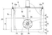
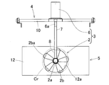
- FIGS. 1 to 4 A water collecting device for a hydroelectric power generation device and a hydroelectric power generation device according to the first embodiment of the present invention will be described with reference to FIGS. 1 to 4.
- this hydroelectric power generation device is installed in, for example, a water channel 1 having running water such as a river or an irrigation canal, and generates power by receiving rotation of a water turbine blade 2.
- the water channel 1 is composed of, for example, a bottom surface portion 1a made of concrete or the like and side wall surface portions 1b on both sides.
- the side wall surface portion 1b is perpendicular to the bottom surface portion 1a, but the side wall surface portion 1b may be oblique.
- the hydroelectric power generation device includes a hydroelectric power generation module 3, a support member 4 for supporting the hydroelectric power generation module 3, and a water collecting device 5 described later.
- the hydroelectric power generation module 3 has a water turbine blade 2 and a generator 6 that generates electricity by the rotation of the water turbine blade 2. That is, the water turbine blade 2 and the generator 6 are fixed to the water channel 1 via the support member 4.
- the turbine blade 2 is installed in a state of being immersed in running water of the water channel 1 (FIG. 1), and converts hydraulic power into rotational force.
- the turbine blade 2 is a propeller type in which the rotation axis (center of rotation) O1 is parallel to the direction in which the flowing water flows.
- the water turbine blade 2 has a hub 2a provided at the center of rotation, and a plurality of (for example, five) blades 2b extending radially outward from the outer peripheral surface of the hub 2a. The tip of each blade 2b is inclined toward the upstream side.
- the rotating shaft (not shown) is rotatably supported coaxially with the hub 2a.
- the rotation of the rotating shaft is accelerated by, for example, a gear portion composed of a pair of meshing bevel gears and the like, and the center of rotation is converted from the axial direction (flow direction) of the hub 2a to the vertical direction.
- These rotating shafts and gear portions are housed in the gear box Gb.
- the generator 6 is, for example, a permanent magnet synchronous type, an induction type or the like three-phase AC generator, or a single-phase AC generator.
- the input shaft 6a of the generator 6 extends in the vertical direction in the support cylinder 7.
- the lower end of the input shaft 6a and the upper end of the power transmission shaft 8 are coaxially connected via a rotary connector (not shown).
- the axis of the power transmission shaft 8 and the axis of the rotation axis are arranged so as to be orthogonal to each other.
- the power transmission shaft 8 is rotatably supported by the support cylinder 7 by a bearing (not shown) in the support cylinder 7. Therefore, the rotation of the rotating shaft is transmitted to the power transmission shaft 8 and the input shaft 6a, so that the generator 6 generates electricity.
- the support member 4 has a pair of fixtures 9 and 9, a horizontal support member 10, and a generator stand 11.
- the fixture 9 is fixed from the vicinity of the upper end to the upper end of the side wall surface portion 1b of the water channel 1.
- One fixture 9 is provided on each of the two side wall surface portions 1b, and a pair of fixtures 9 and 9 face each other in the width direction of the water channel.
- Each fixture 9 is formed from, for example, an angle having an L-shaped cross section.
- the horizontal support member 10 is a rod-shaped member supported by a pair of fixtures 9, 9. That is, the horizontal support member 10 is hung between the upper ends of the side wall surfaces 1b of the water channel 1 by a pair of fixtures 9 and 9.
- a generator stand 11 is fixed near the middle of the horizontal support member 10 in the longitudinal direction (width direction of the water channel 1), and the generator 6 is supported by the generator stand 11.
- the water collecting device 5 is installed on the upstream side of the water turbine blade 2 and collects the water in the water channel 1 in the water turbine blade 2.
- the water collecting device 5 has a water collecting plate 12 and water collecting plate guides 13 and 13.
- the water collecting plate guides 13 and 13 are installed on both sides of the water channel 1 and guide the water collecting plate 12 so as to be movable up and down.
- the water collecting plate 12 is, for example, a rectangular plate member made of steel, resin, wood, concrete, or the like.
- the water collecting plate 12 has a water passage hole 12a, and blocks the water channel 1 to collect the flowing water of the water channel 1 in the water passage hole 12a. That is, the water collecting plate 12 narrows the cross section of the flowing water flow path by the area of the water passage hole 12a. Therefore, the flow velocity of the water passing through the turbine blade 2 increases, and the power generation efficiency can be improved.
- the water collecting plate 12 is installed in the water channel 1 so that the center L1 of the water passage hole 12a of the water collecting plate 12 and the rotation center L2 of the water turbine blade 2 coincide with each other.
- the water turbine blade 2 installed in the state of being submerged in the running water of the water channel 1 is at the same depth position and the same in the water channel 1.
- the water passage hole 12a of the water collecting plate 12 is located at a position in the width direction. Further, the maximum height H of the water collecting plate 12 is set lower than the depth H1 of the water channel 1.
- the water passage hole 12a of the water collecting plate 12 is circular when viewed from the front of the water collecting plate 12. That is, it is a through hole composed of a water passage hole 12a round hole. Further, the area of the water passage hole 12a is set to be smaller than the area (rotational area) of the circle Cr passing through the outer peripheral edge portion 2ba of the plurality of blades 2b in the water turbine blade 2. Specifically, the radius of the water passage hole 12a is set to 0.75 times or more and less than 0.98 times the radius of gyration of the turbine blade 2. When the radius of the water passage hole 12a is less than 0.75 times the radius of gyration of the turbine blade 2, the fatigue strength applied to the turbine blade 2 becomes large, the output power is not stable, and the burden on the machine body is large.
- the distance x in the axial direction (direction parallel to the flowing water flow direction) between the water passage hole 12a and the tip of the blade takes into account the generated power (FIG. 9) and its dispersion (FIG. 10) described later. Then, it is set by a test or a simulation.
- the "wing tip” means the outer peripheral edge portion 2ba of the blade 2b.
- each water collecting plate guide 13 is a rail member having a guide groove 13a having a cross section perpendicular to the longitudinal direction, that is, a horizontal cross section having a concave shape.
- the water collecting plate guide 13 for example, channel steel, a resin material having a concave cross-sectional shape, a concrete material, or the like is applied. In addition, it may be a member obtained by machining a steel plate, a steel material, or a resin material bent into a groove shape into a concave cross-sectional shape.
- the water collecting plate guides 13 and 13 are installed along the vertical direction on the side wall surface portions 1b on both sides of the water channel 1.
- the guide grooves 13a and 13a of both water collecting plate guides 13 and 13 face each other in the width direction of the water channel. Both side edges of the water collecting plates 12 are guided to the guide grooves 13a, 13a of the water collecting plate guides 13, 13. In this way, the water collecting plate 12 is guided by the water collecting plate guides 13 and 13 so as to be movable up and down.
- the area of the water passage hole 12a of the water collecting plate 12 is smaller than the area of the circular Cr passing through the outer peripheral edge portion 2ba of the turbine blade 2, the so-called rotating area. Therefore, all the water flow from the water passage hole 12a can be applied to the blade of the hydroelectric power generation device. As a result, the energy of the water stream can be used without waste, and the power generation efficiency can be improved as compared with the conventional technology.
- the radius of the water passage hole 12a is set to 0.75 to 0.98 times the radius of gyration of the turbine blade 2. As a result, a sufficient amount of water flow passing through the water passage hole 12a is secured, and all the water flow discharged from the water passage hole 12a can be applied to the water turbine blade 2. As a result, the energy of the water stream can be used more efficiently.
- the shape of the water passage hole 12a is approximately circular, the unevenness of the water flow received by each of the plurality of blades 2b constituting the water turbine blade 2 during rotation can be reduced, and the repetitive stress applied to the blades 2b can be reduced. As a result, it is possible to suppress a decrease in the life of the turbine blade 2. In addition, the generated power is stabilized by reducing the unevenness of the water flow. Further, since the center L1 of the water passage hole 12a and the rotation center L2 of the turbine blade 2 coincide with each other, the unevenness of the water flow received by each blade 2b during rotation can be surely reduced. Therefore, the repetitive stress applied to the blade 2b can be reliably reduced.
- the water collecting device 5 can be easily installed only by installing the water collecting plate guides 13 on both sides of the water channel 1 and then inserting the water collecting plates 12 along the water collecting plate guides 13 and 13. Since the maximum height H of the water collecting plate 12 is set lower than the depth H1 of the water channel 1, even if the water level of the water channel 1 on the upstream side of the turbine blade 2 rises, the water exceeds the water collecting plate 12. Flow. Therefore, it is possible to prevent water from overflowing from the water channel 1.
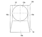
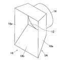
- 5A to 5C are diagrams of the water collecting device 5A for the hydroelectric power generation device according to the second embodiment.
- 5A is a front view of the water collecting device 5A
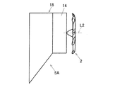
- FIG. 5B is a side view of the water collecting device 5A
- FIG. 5C is a perspective view of the water collecting device 5A.
- 6A and 6B are diagrams showing the positional relationship between the water collecting device 5A and the water turbine blade 2.
- a rectangular frame-shaped frame member 18 extending upstream from the outer peripheral edge of the water collecting plate 12 is attached. Both side wall portions 18a, 18a of the frame member 18 are inclined in a direction that becomes wider toward the upstream side. Further, the lower side wall portion 18b of the frame member 18 is inclined downward toward the upstream side.
- a tubular member (discharge pipe portion) 14 extending cylindrically from the peripheral edge portion of the water passage hole 12a to the downstream side is attached.
- the tubular member 14 is arranged at a position that does not interfere with the water turbine blade 2. With such a frame member 18, running water can be efficiently collected on the upstream side of the water passage hole 12a.
- the tubular member 14 makes it possible to efficiently apply all the water flow from the water passage hole 12a to the blades of the hydroelectric power generation device. Other than that, it has the same effect as that of the above-described embodiment.
- FIG. 7 is a front view showing an example in which the diameter of the water passage hole 12a is 0.95 times the diameter of the turbine blade 2 in the water collecting device 5A.
- FIG. 8 is a front view showing an example in which the diameter of the water passage hole 12a is 0.75 times the diameter of the water turbine blade 2 in the water collecting device 5A.
- FIG. 10 is a diagram showing the distribution of generated power with respect to the distance between the water passage hole and the tip of the wing.
- the distribution of generated power is small. That is, stable generated power can be obtained, the fatigue load applied to the blades is small, and the load on the machine body is also small.
- the water flow hole diameter ratio is "0.75" and "0.74"
- the power generation is widely dispersed
- the water flow hole diameter ratio is "0.74"
- the water flow hole and the tip of the blade have the maximum power generation. Large dispersion over distance. That is, the generated power is not stable, the fatigue load applied to the blade becomes large, and the burden on the machine body is large.
- the water passage hole 12a of the water collecting plate 12 is not limited to the round hole, and may be, for example, an elliptical shape. Further, the center L1 of the water passage hole 12a and the rotation center L2 of the turbine blade 2 do not have to coincide with each other. Further, the water collecting plate guide 13 may be omitted, and the water collecting plate 12 may be fixedly installed in the water channel 1. In the water collecting device 5A having the frame member 18, for example, the water collecting device 5A may be installed in the middle of the flow path without blocking the entire water channel. In the water collecting device 5A having the frame member 18, the tubular member 14 can be omitted.
- FIGS. 11 to 18 A third embodiment of the present invention will be described with reference to FIGS. 11 to 18. Since the schematic configuration of the entire hydroelectric power generation device, the hydroelectric power generation module 3, and the configuration of the water collecting plate 12 of the water collecting device 5 are the same as those in the first embodiment described above, detailed description thereof will be omitted. In FIG. 11, the water collecting plate 12 is indicated by a two-dot chain line.
- the support member 4 of this embodiment also has a pair of fixtures 9 and 9 shown in FIG. 11, a horizontal support member 10, and a generator stand 11.
- the fixtures 9 and 9 are installed from the vicinity of the upper end of the side walls 1b and 1b of the water channel 1 to the upper end portion.
- the fixture 9 has, for example, an angle having an L-shaped cross section, and its longitudinal direction extends along the water channel 1. That is, the fixture 9 constitutes a component along the side wall 1b of the water channel 1 in the support member 4.
- the fixture 9 is not limited to this.
- the pair of fixtures 9 and 9 are fixed to the side walls 1b and 1b so as to face each other in the width direction of the water channel.
- the fixing of the fixture 9 to the side wall 1b of the water channel 1 is, for example, bolted.
- the horizontal support member 10 is a rod-shaped member extending in the width direction of the water channel 1, and both ends thereof are supported by a pair of fixtures 9 and 9. That is, the horizontal support member 10 is hung between the upper ends of the side wall surfaces 1b of the water channel 1 by a pair of fixtures 9 and 9. In this way, the horizontal support member 10 constitutes a member that straddles the water channel 1 in the support member 4.
- the horizontal support member 10 of this embodiment is a square pipe having a quadrangular cross-sectional shape. However, the horizontal support member 10 is not limited to the square pipe.
- the horizontal support member 18 is bolted to the fixture 16 via the mounting bracket 19 of FIG. However, the method of supporting the horizontal support member 18 is not limited to this.
- the generator stand 11 is fixed near the middle of the horizontal support member 10 in the longitudinal direction (width direction of the water channel 1), and the generator 6 is supported by the generator stand 10.
- the generator base 11 is joined to the horizontal support member 10 by welding, and the generator 6 is detachably attached to the generator base 11 by bolts (not shown).
- the mounting method of the generator 6 and the generator stand 11 is not limited to this.
- the water collecting plate guide 13 of this embodiment is fixed to a part of the support member 4.
- the water collecting plate guide 13 is fixed to the horizontal support member 10 which is the support member 4.
- the water collecting plate guide 13 is fixed to the horizontal support member 10 via the guide support component 28.
- the guide support component 28 is detachably bolted to the horizontal support member 10, and the water collecting plate guide 13 is detachably bolted to the guide support component 28.
- the water collecting plate guide 13 is fixed to the support member 4 so as to be movable in the water flow direction. That is, the hydroelectric power generation device includes a movable mechanism 30 that allows the water collecting plate guide 13 to move in the direction of water flow. The details of the movable mechanism 30 of this embodiment will be described below.
- the guide support component 28 is attached to the upper surface of the horizontal support member 10.
- the guide support component 28 is made of a flat plate, and an oval elongated hole 32 facing in the vertical direction is formed.
- the longitudinal direction of the elongated hole 32 coincides with the flow direction of water.
- an upwardly facing screw hole 34 is formed on the upper surface of the horizontal support member 10.
- the support structure of the water collecting plate guide 13 to the horizontal support member 10 will be described.
- the bolt 36 is inserted into the elongated hole 32 from above and tightened into the screw hole 34.
- the water collecting plate guide 13 is connected to the guide support component 28 by a bolt (not shown).
- the water collecting plate guide 13 is supported by the horizontal support member 10 via the guide support component 28.
- the water collecting plate guide 13 and the guide support component 28 may be connected before the guide support component 28 is connected to the horizontal support member 10.
- the water collecting plate guide 13 is movable in the water flow direction with respect to the support member 4, that is, the position is fixed so as to be changeable.
- To. 13 and 14 show a state in which the water collecting plate guide 13 is fixed to the support member 4 on the downstream side of the water flow direction A1.
- FIGS. 15 and 16 show a state in which the water collecting plate guide 13 is fixed to the support member 4 on the upstream side of the water flow direction A1.
- the movable mechanism 30 is composed of the screw holes 34 of the horizontal support member 10, the elongated holes 32 of the guide support component 28, and the bolts 36.
- FIGS. 17A to 17D The procedure for installing the hydroelectric power generation device of this embodiment in the water channel 1 will be described with reference to FIGS. 17A to 17D.
- the hydroelectric power generation device is installed in the water channel 1 from above by using a crane or the like.
- the fixtures 9 and 9 are fixed to the side wall 1b of the water channel 1 by fastening means such as bolts and nuts (not shown).
- the water collecting plate 12 shown in FIG. 17D is installed in the hydroelectric power generation device. Specifically, both side edges of the water collecting plate 12 are inserted into the guide grooves 13a and 13a (FIG. 13) of the water collecting plate guides 13 and 13 from above. As a result, the water collecting plate 12 is guided downward by the water collecting plate guides 13 and 13. As described above, the hydroelectric power generation device is installed in the water channel 1.
- the water collecting device 5 can be easily installed by using the water turbine blade 2 and the support member 4 of the generator 6 for fixing the water collecting device 5. Further, since the water collecting plate guide 13 can be fixed according to the width of the water channel 1, the water collecting effect of the water collecting plate 12 can be maximized. In particular, when the flow rate is small, the amount of power generated by the generator 6 can be efficiently increased by collecting water without waste.
- the water collecting plate guide 13 is fixed to the horizontal support member 10 which is a member straddling the water channel 1.
- the catchment plate guide 13 installed on the side wall 1b of the water channel 1 can be easily installed at the same position when viewed from the water flow direction in the water channel 1. Therefore, the installation work becomes easy.
- the movable mechanism 30 movably supports the water collecting plate guide 13 with respect to the horizontal support member 10 which is one of the support members 4 in the water flow direction A1.
- the movable mechanism 30 movably supports the water collecting plate guide 13 with respect to the horizontal support member 10 which is one of the support members 4 in the water flow direction A1.
- FIGS. 18 to 20 A fourth embodiment of the present invention will be described with reference to FIGS. 18 to 20.
- the same components as those in the third embodiment are designated by the same reference numerals, and the description thereof will be omitted.
- the water collecting plate guide 13 is fixed to the horizontal support member 10 which is a member straddling the water channel 1 in the support member 4, whereas in the fourth embodiment, the water channel 1 in the support member 4 is fixed.
- the water collecting plate guide 13 is fixed to the fixture 9 which is a component along the side wall 1b of the water collecting plate.
- the water collecting plate guide 13 is fixed to the fixture 9 via the guide support component 40.
- the guide support component 40 is detachably bolted to the fixture 9, and the water collecting plate guide 13 is detachably bolted to the guide support component 40.
- the guide support component 40 is attached to the inner surface of the fixture 9 (the surface facing the water channel 1).
- the guide support component 40 is made of a flat plate, and an oval elongated hole 42 facing the horizontal direction (the width direction of the water channel 1) is formed.
- the longitudinal direction of the elongated hole 42 coincides with the water flow direction A1.
- the fixture 9 is formed with a screw hole 44 facing in the horizontal direction (width direction of the water channel 1).
- the support structure of the water collecting plate guide 13 to the fixture 9 will be described.
- the bolt 46 is inserted into the elongated hole 42 from the horizontal direction (inside in the width direction of the water channel 1) and tightened into the screw hole 44.
- the water collecting plate guide 13 is connected to the guide support component 40.
- the connection of the water collecting plate guide 13 to the guide support component 40 may be a bolt connection or a welding connection.
- the water collecting plate guide 13 is supported by the fixture 9 via the guide support component 40.
- the water collecting plate guide 13 and the guide support component 40 may be connected before the guide support component 40 is connected to the fixture 9.
- FIG. 18 shows a state in which the water collecting plate guide 13 is fixed to the support member 4 on the downstream side of the water flow direction A1.
- FIG. 20 shows a state in which the water collecting plate guide 13 is fixed to the support member 4 on the upstream side of the water flow direction A1.
- the movable mechanism 50 (FIG. 19) is configured by the screw hole 44 of the fixture 9, the elongated hole 42 of the guide support component 40, and the bolt 46.
- the water collecting device 5 for concentrating the water flow can be easily installed in the water channel 1. Further, according to the fourth embodiment, since the water collecting plate guide 13 is fixed to the fixture 9 which is a component along the side wall 1b of the water channel 1, the water collecting plate guide 13 is placed on one side of the side wall 1b of the water channel 1. Can be fixed one by one. As a result, it is possible to reduce a large load in the water flow direction applied to the water collecting plate guide 13 when the water is installed in the water channel 1 having a water flow.
- the present invention is not limited to the above embodiments, and various additions and modifications are made without departing from the gist of the present invention. Or it can be deleted.
- the support member 4 and the guide support component 28 (40) are provided with the movable mechanism 30 (50), but the movable mechanism 30 (50) is the support member 4, It may be provided on at least one of the water collecting plate guide 13 and the guide support component 28 (40). Therefore, such things are also included within the scope of the present invention.
- the inventions according to the embodiments of FIGS. 11 to 20 include the following aspects 1 to 5 that do not require a water passage hole.
- the hydroelectric power generator of the first aspect is an impeller that converts hydraulic power into rotational force, a generator that generates power by the rotation of the impeller, and is installed on the upstream side of the impeller to collect water from the water channel in the impeller.
- a hydroelectric power generator provided with a water collecting device, wherein the impeller and the generator are fixed to the water channel via fixing parts, and the water collecting device accelerates water in the water channel. It has a water collecting plate that guides the impeller and a water collecting plate guide that installs the water collecting plate in the water channel.
- the water collecting plate guide is installed on the side surface of the water channel, and the water collecting plate guide It is fixed to a part of the fixed parts and arranged on the upstream side of the water channel with respect to the impeller.
- the water collecting device can be easily installed by using the fixing parts of the impeller and the generator for fixing the water collecting device. Further, since the water collecting plate guide can be fixed according to the width of the water channel, the water collecting effect of the water collecting plate can be maximized. In particular, when the flow rate is small, the amount of power generated by the generator can be efficiently increased by collecting water without waste.
- the fixing component has a member straddling the water channel, and the water collecting plate guide may be fixed to the member straddling the water channel.
- the water collecting plate guides installed on the side walls of the waterways on both sides can be easily placed at the same position when viewed in the direction of water flow in the waterways. Can be installed. Therefore, the installation work becomes easy.
- the fixing component has a component along the side wall of the water channel, and the water collecting plate guide may be fixed to the component along the side wall of the water channel.
- the water collecting plate guide can be fixed to the side wall of the water channel one side at a time, and the load of the water collecting plate guide applied in the water flow direction at the time of installation in the water channel having a water flow can be reduced.
- a movable mechanism that allows the water collecting plate guide to move in the flow direction of water is further provided, and the fixing component, the water collecting plate guide, and the fixed component are provided with the water collecting.
- the movable mechanism may be provided on at least one of the support parts that support the plate guide.
- the water collecting plate may have a water passage hole in the impeller facing the water flow direction. According to this configuration, the cross section of the flow path of the flowing water is narrowed to the area of the water passage hole, so that the flow velocity of the water passing through the impeller increases. As a result, the power generation efficiency can be improved.
Landscapes
- Engineering & Computer Science (AREA)
- Chemical & Material Sciences (AREA)
- Combustion & Propulsion (AREA)
- Mechanical Engineering (AREA)
- General Engineering & Computer Science (AREA)
- Power Engineering (AREA)
- Hydraulic Turbines (AREA)
Abstract
この水力発電装置用集水装置は、水路に浸かり水力を回転力に変換する水車翼(2)と、この水車翼(2)の回転により発電する発電機(6)とを備えた水力発電装置に用いられる。水力発電装置用集水装置は、水車翼(2)の上流側に設置されて水車翼(2)に水路の水を集水する。この集水装置(5)は、通水孔(12a)を有し水路の流水を通水孔(12a)に集める集水板(12)を備え、この集水板(12)の通水孔(12a)の面積が、水車翼(2)の外周縁部(2ba)を通る円(Cr)の面積より小さい。また、通水孔(12a)の形状を集水板(12)の正面視で円形としている。
Description
この出願は、2019年3月13日出願の特願2019-045353および2019年3月20日出願の特願2019-053409の優先権を主張するものであり、その全体を参照により本願の一部をなすものとして引用する。
この発明は、水路に設置される水力発電装置用集水装置および水力発電装置に関し、水車翼を通過する流速を増加させ、発電効率を高める技術に関する。
水路を流れる水流を受けて回転するプロペラよりも上流側に枠部材を備え、この枠部材の上流側開口部の上方に壁部を有することで水流を集中させ、弱い水流であっても十分な発電を行える水流発電装置が提案されている(特許文献1)。この水流発電装置は、水車より上流側に位置する枠部材の上流側開口部から下流側開口部まで開口面積を狭めることで、水流を一層集中させることができる。
特許文献1は、プロペラの羽根の回転面積を枠部材の下流側開口部の面積以下とすることで、水流を効率的に受けて発電効率を高めることを目的としている。しかしながら、プロペラより上流側にある枠部材の下流側開口部から流れる水流の一部は、プロペラの羽根が抵抗となるので、抵抗の小さいプロペラの羽根の回転半径より外側で、且つ下流側開口部より内側を通る。この範囲はプロペラの効率に寄与しない範囲であり、水流のエネルギーの一部を無駄にしている。
この発明の目的は、水流のエネルギーを無駄なく利用して発電効率を高めることができる水力発電装置用集水装置および水力発電装置を提供することである。
この発明の水力発電装置用集水装置は、水路に浸かり水力を回転力に変換する水車翼と、この水車翼の回転により発電する発電機とを備えた水力発電装置に用いられる。集水装置は、前記水車翼の上流側に設置されて前記水車翼に前記水路の水を集水する。
集水装置は、通水孔を有し前記水路の流水を前記通水孔に集める集水板を備えている。この集水板の前記通水孔の面積が、前記水車翼の外周縁部を通る円の面積より小さい。
集水装置は、通水孔を有し前記水路の流水を前記通水孔に集める集水板を備えている。この集水板の前記通水孔の面積が、前記水車翼の外周縁部を通る円の面積より小さい。
この構成によると、集水板の通水孔を通過した水が水車翼に集水することによって、水車翼が回転し、この水車翼の回転より発電機が発電する。通水孔から出る水流の流速は、集水板よりも上流を流れる水流の流速より速く、水車翼を効率的に回転することができる。特に、集水板の通水孔の面積が、水車翼の外周縁部を通る円の面積、すなわち、回転面積より小さいので、通水孔から出る水流の全てを水力発電装置の翼に当てることができる。これにより、水流のエネルギーは無駄なく利用され、従来技術よりも発電効率を高めることができる。
この発明において、前記通水孔の形状は、前記集水板の正面視で円形であってもよい。通水孔の形状を概ね円形とすることで、水車翼を構成する複数枚のブレードのそれぞれが回転中に受ける水流のムラが小さくなり、ブレードにかかる繰り返し応力を小さくできる。これにより、水車翼の寿命低下を抑えることができる。また、水流のムラが小さくなることで、発電電力が安定する。
この発明において、前記通水孔の中心と前記水車翼の回転中心が一致していてもよい。この場合、各ブレードが回転中に受ける水流のムラを確実に小さくすることができ、ブレードにかかる繰り返し応力を確実に小さくできる。
この発明において、前記通水孔の半径が、前記水車翼の回転半径の0.75倍~0.98倍であってもよい。ここで、「0.75倍~0.98倍」とは、0.75倍以上0.98倍未満と同義である。この場合、通水孔を通過する水流の量が十分に確保され、通水孔から出る水流の全てを水車翼に当てることができる。これにより、さらに効率良く水流のエネルギーを利用できる。通水孔の半径が水車翼の回転半径の0.75倍未満の場合、水車翼にかかる疲労強度が大きくなり、出力電力が安定せず機械体への負担が大きい。
この発明の水力発電装置は、前記水車翼と、前記発電機と、この発明の水力発電装置用集水装置とを備えている。これにより、この発明の水力発電装置用集水装置につき前述した各効果が得られる。
この発明の水力発電装置において、前記水車翼および前記発電機は支持部材を介して前記水路に固定され、前記集水装置は、前記集水板を前記水路に設置する集水板ガイドを有し、前記集水板ガイドは前記水路の側面に設置され、前記集水板ガイドが前記支持部材の一部に固定されて、前記水車翼に対して前記水路の上流側に配置されていてもよい。
この構成によると、集水装置の固定に水車翼および発電機の支持部材を利用することで、集水装置の設置を容易に行うことができる。また、集水板ガイドを水路の幅に合わせて固定することができるので、集水板による集水効果を最大限に利用できる。特に、流量が少ない場合、無駄なく集水することで、発電機の発電量を効率よく増加できる。
この場合、前記支持部材は水路を跨ぐ部材を有しており、前記水路をまたぐ部材に、前記集水板ガイドが固定されていてもよい。この構成によれば、水路をまたぐ部材に集水板ガイドを固定することで、両側の水路側壁に設置される集水板ガイドを、水路の水の流れる方向で見て同一の位置に容易に設置できる。このため、設置作業が簡単になる。
また、前記支持部材は水路の側壁に沿う部品を有して、前記水路の側壁に沿う部品に前記集水板ガイドが固定されていてもよい。この構成によれば、水路の側壁に集水板ガイドを片側ずつ固定でき、水流のある水路への設置時に水の流れ方向にかかる集水板ガイドの負荷を軽減できる。
この発明の水力発電装置において、さらに、水の流れ方向に前記集水板ガイドを移動可能とする可動機構を備え、前記支持部材、前記集水板ガイド、前記支持部材に前記集水板ガイドを支持する支持部品の少なくとも一つに、前記可動機構が設けられていてもよい。この構成によれば、支持部材と集水板ガイドとの間で、水の流れ方向に自由度を持たせることで、発電機と集水板ガイド間の水の流れ方向の距離を変えることができる。これにより、水量や流速に合わせて発電機に対する最適な位置に集水板ガイドおよび集水板を設置でき、発電量を効率よく増加させることができる。
請求の範囲および/または明細書および/または図面に開示された少なくとも2つの構成のどのような組合せも、この発明に含まれる。特に、請求の範囲の各請求項の2つ以上のどのような組合せも、この発明に含まれる。
本発明は、添付の図面を参考にした以下の好適な実施形態の説明からより明瞭に理解されるであろう。しかしながら、実施形態および図面は単なる図示および説明のためのものであり、本発明の範囲を定めるために利用されるべきでない。本発明の範囲は添付のクレーム(請求の範囲)によって定まる。添付図面において、複数の図面における同一の部品番号は、同一部分を示す。
この発明の第1の実施形態に係る水力発電装置の斜視図である。
同水力発電装置を水路の上流側から見た正面図である。
同水力発電装置の側面図である。
同水力発電装置を水路の下流側から見た背面図である。
この発明の第2の実施形態に係る水力発電装置用集水装置の正面図である。
同水力発電装置用集水装置の側面図である。
同水力発電装置用集水装置の斜視図である。
同集水装置と水車翼との位置関係を示す側面図である。
同集水装置と水車翼との位置関係を示す斜視図である。
通水孔の直径が水車翼の直径の0.95倍の例を示す正面図である。
通水孔の直径が水車翼の直径の0.75倍の例を示す正面図である。
通水孔と翼先端との距離に対する発電電力の比較を示す図である。
通水孔と翼先端との距離に対する発電電力の分散を示す図である。
この発明の第3の実施形態に係る水力発電装置を示す正面図である。
同水力発電装置を示す側面図である。
同水力発電装置を示す平面図である。
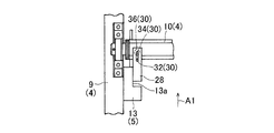
図13の集水板ガイドの取り付け部を拡大して示す平面図である。
同水力発電装置の図13とは位置を変えた状態を示す平面図である。
図15の集水板ガイドの取り付け部を拡大して示す平面図である。
同水力発電装置を水路に設置する状況を示す正面図である。
同水力発電装置を水路に設置する状況を示す正面図である。
同水力発電装置を水路に設置する状況を示す正面図である。
同水力発電装置を水路に設置する状況を示す正面図である。
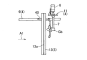
この発明の第4の実施形態に係る水力発電装置を示す側面図である。
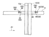
図18の集水板ガイドの取り付け部を拡大して示す側面図である。
同水力発電装置の図18とは位置を変えた状態を示す側面図である。
[第1の実施形態]
この発明の第1の実施形態に係る水力発電装置用集水装置および水力発電装置を図1ないし図4と共に説明する。
<水力発電装置全体の概略構成>
図1~図4に示すように、この水力発電装置は、例えば、河川、用水路等の流水のある水路1に設置され、水車翼2の回転を受けて発電を行う。水路1は、例えば、それぞれコンクリート等から成る底面部1aおよび両側の側壁面部1bで構成される。各図の例では、底面部1aに対して側壁面部1bが垂直になっているが、側壁面部1bは斜めになっていてもよい。また、底面部1aと側壁面部1bの角部が図のような直角状でなく、底面部1aと側壁面部1bとが曲面で繋がっていてもよい。水力発電装置は、水力発電モジュール3と、この水力発電モジュール3を支持する支持部材4と、後述する集水装置5とを備えている。
この発明の第1の実施形態に係る水力発電装置用集水装置および水力発電装置を図1ないし図4と共に説明する。
<水力発電装置全体の概略構成>
図1~図4に示すように、この水力発電装置は、例えば、河川、用水路等の流水のある水路1に設置され、水車翼2の回転を受けて発電を行う。水路1は、例えば、それぞれコンクリート等から成る底面部1aおよび両側の側壁面部1bで構成される。各図の例では、底面部1aに対して側壁面部1bが垂直になっているが、側壁面部1bは斜めになっていてもよい。また、底面部1aと側壁面部1bの角部が図のような直角状でなく、底面部1aと側壁面部1bとが曲面で繋がっていてもよい。水力発電装置は、水力発電モジュール3と、この水力発電モジュール3を支持する支持部材4と、後述する集水装置5とを備えている。
<水力発電モジュール3について>
図3および図4に示すように、水力発電モジュール3は、水車翼2、およびこの水車翼2の回転により発電する発電機6を有する。つまり、水車翼2および発電機6が支持部材4を介して水路1に固定されている。
図3および図4に示すように、水力発電モジュール3は、水車翼2、およびこの水車翼2の回転により発電する発電機6を有する。つまり、水車翼2および発電機6が支持部材4を介して水路1に固定されている。
<水車翼2>
水車翼2は、水路1(図1)の流水中に浸かる状態で設置され、水力を回転力に変換する。水車翼2は、回転軸心(回転中心)O1が流水の流れる方向と平行なプロペラ型である。水車翼2は、回転軸心に設けられるハブ2aと、このハブ2aの外周面から半径方向外方に放射状に延びる複数(例えば5枚)のブレード2bとを有する。各ブレード2bの先端部は、上流側に向けて傾斜している。
水車翼2は、水路1(図1)の流水中に浸かる状態で設置され、水力を回転力に変換する。水車翼2は、回転軸心(回転中心)O1が流水の流れる方向と平行なプロペラ型である。水車翼2は、回転軸心に設けられるハブ2aと、このハブ2aの外周面から半径方向外方に放射状に延びる複数(例えば5枚)のブレード2bとを有する。各ブレード2bの先端部は、上流側に向けて傾斜している。
回転軸(図示せず)がハブ2aに同軸に回転自在に支持されている。この回転軸の回転は、例えば、噛み合う一対の傘歯車等から成るギヤ部により増速され、且つ、回転軸心がハブ2aの軸心方向(流れ方向)から上下方向に変換される。これら回転軸およびギヤ部は、ギヤボックスGb内に収容されている。
<発電機6>
発電機6は、例えば、永久磁石同期型、誘導型等の三相交流発電機、または単相交流の発電機である。発電機6の入力軸6aが支持筒7内を上下方向に延びている。支持筒7内において、入力軸6aの下端と動力伝達軸8の上端とが、回転連結具(図示しない)を介して同軸に連結されている。動力伝達軸8の軸心と前記回転軸の軸心とは直交するように配置されている。動力伝達軸8は、支持筒7内の軸受(図示せず)により、支持筒7に回転自在に支持されている。したがって、前記回転軸の回転が動力伝達軸8および入力軸6aに伝達されることで、発電機6が発電する。
発電機6は、例えば、永久磁石同期型、誘導型等の三相交流発電機、または単相交流の発電機である。発電機6の入力軸6aが支持筒7内を上下方向に延びている。支持筒7内において、入力軸6aの下端と動力伝達軸8の上端とが、回転連結具(図示しない)を介して同軸に連結されている。動力伝達軸8の軸心と前記回転軸の軸心とは直交するように配置されている。動力伝達軸8は、支持筒7内の軸受(図示せず)により、支持筒7に回転自在に支持されている。したがって、前記回転軸の回転が動力伝達軸8および入力軸6aに伝達されることで、発電機6が発電する。
<支持部材4>
図1に示すように、支持部材4は、一対の固定具9,9と、水平支持材10と、発電機台11とを有する。固定具9は、水路1の側壁面部1bにおける上端付近から上端部に渡り固定されている。固定具9は2つの側壁面部1bに一つずつ設けられており、一対の固定具9,9が水路幅方向に互いに対向している。各固定具9は、例えば、断面L形のアングル等から形成される。水平支持材10は、一対の固定具9,9に支持される棒状部材である。つまり、水平支持材10は、一対の固定具9,9により水路1の両側壁面1bの上端間に掛け渡される。水平支持材10の長手方向(水路1の幅方向)の中間付近に発電機台11が固定され、この発電機台11に発電機6が支持されている。
図1に示すように、支持部材4は、一対の固定具9,9と、水平支持材10と、発電機台11とを有する。固定具9は、水路1の側壁面部1bにおける上端付近から上端部に渡り固定されている。固定具9は2つの側壁面部1bに一つずつ設けられており、一対の固定具9,9が水路幅方向に互いに対向している。各固定具9は、例えば、断面L形のアングル等から形成される。水平支持材10は、一対の固定具9,9に支持される棒状部材である。つまり、水平支持材10は、一対の固定具9,9により水路1の両側壁面1bの上端間に掛け渡される。水平支持材10の長手方向(水路1の幅方向)の中間付近に発電機台11が固定され、この発電機台11に発電機6が支持されている。
<集水装置5について>
図1~図4に示すように、集水装置5は、水車翼2の上流側に設置され前記水車翼2に水路1の水を集水する。集水装置5は、集水板12と、集水板ガイド13,13とを有する。集水板ガイド13,13は、水路1の両側部に設置され、集水板12を上下に移動可能に案内する。集水板12は、例えば、鋼製、樹脂製、木製またはコンクリート製等の矩形状の板部材である。集水板12は通水孔12aを有しており、水路1を遮断して水路1の流水を通水孔12aに集める。つまり、集水板12により流水の流路断面が通水孔12aの面積により狭められる。このため、水車翼2を通過する水の流速が増加し、発電効率の向上を図ることができる。
図1~図4に示すように、集水装置5は、水車翼2の上流側に設置され前記水車翼2に水路1の水を集水する。集水装置5は、集水板12と、集水板ガイド13,13とを有する。集水板ガイド13,13は、水路1の両側部に設置され、集水板12を上下に移動可能に案内する。集水板12は、例えば、鋼製、樹脂製、木製またはコンクリート製等の矩形状の板部材である。集水板12は通水孔12aを有しており、水路1を遮断して水路1の流水を通水孔12aに集める。つまり、集水板12により流水の流路断面が通水孔12aの面積により狭められる。このため、水車翼2を通過する水の流速が増加し、発電効率の向上を図ることができる。
集水板12の通水孔12aの中心L1と水車翼2の回転中心L2とが一致するように、集水板12が水路1に設置されている。換言すれば、集水板12が水路1に設置された状態において、水路1の流水中に没する状態で設置された水車翼2に対し、水路1内において同一の深さ位置で且つ同一の幅方向位置に、集水板12の通水孔12aが位置する。また、集水板12の最大高さHは、水路1の深さH1よりも低く設定されている。
集水板12の通水孔12aは、この集水板12の正面視で円形である。つまり、通水孔12a丸孔から成る貫通孔である。また、通水孔12aの面積が、水車翼2における複数のブレード2bの外周縁部2baを通る円Crの面積(回転面積)より小さく設定されている。具体的には、通水孔12aの半径は、水車翼2の回転半径の0.75倍以上0.98倍未満に設定されている。通水孔12aの半径が水車翼2の回転半径の0.75倍未満の場合、水車翼2にかかる疲労強度が大きくなり、出力電力が安定せず機械体への負担が大きい。
図3に示すように、通水孔12aと翼先端との軸方向(流水の流れる方向と平行な方向)の距離xは、後述する発電電力(図9)およびその分散(図10)を加味して、試験またはシミュレーション等により設定される。ここで、「翼先端」とは、ブレード2bの外周縁部2baを意味する。
図1および図2に示すように、各集水板ガイド13は、長手方向に垂直な断面、すなわち水平断面が凹形状の案内溝13aを有するレール部材である。この集水板ガイド13として、例えば、溝形鋼、凹断面形状の樹脂材またはコンクリート材等が適用される。その他、溝形に曲げ加工した鋼板、鋼材または樹脂材を凹断面形状に機械加工した部材であってもよい。集水板ガイド13,13は、水路1の両側の側壁面部1bに上下方向に沿って設置されている。両集水板ガイド13,13の案内溝13a,13aは、水路幅方向に対向している。両集水板ガイド13,13の案内溝13a,13aに、集水板12の両側縁部が案内される。このように、集水板12は、集水板ガイド13,13により上下に移動可能に案内される。
<作用効果>
以上説明した集水装置5および水力発電装置によれば、集水板12の通水孔12aを通過した水を水車翼2に集水する。これにより、水車翼2が回転し、この水車翼2の回転より発電機6が発電する。通水孔12aから出る水流の流速は、集水板12よりも上流を流れる水流の流速より速く、水車翼2を効率的に回転することができる。
以上説明した集水装置5および水力発電装置によれば、集水板12の通水孔12aを通過した水を水車翼2に集水する。これにより、水車翼2が回転し、この水車翼2の回転より発電機6が発電する。通水孔12aから出る水流の流速は、集水板12よりも上流を流れる水流の流速より速く、水車翼2を効率的に回転することができる。
特に、集水板12の通水孔12aの面積が、水車翼2の外周縁部2baを通る円Crの面積、いわゆる回転面積より小さい。このため、通水孔12aから出る水流の全てを水力発電装置の翼に当てることができる。その結果、水流のエネルギーを無駄なく利用することができ、従来技術よりも発電効率を高めることができる。また、通水孔12aの半径が水車翼2の回転半径の0.75倍~0.98倍に設定されている。これにより、通水孔12aを通過する水流の量が十分に確保され、通水孔12aから出る水流の全てを水車翼2に当てることができる。その結果、水流のエネルギーをより効率良く利用できる。
通水孔12aの形状が概ね円形であるから、水車翼2を構成する複数枚のブレード2bのそれぞれが回転中に受ける水流のムラが小さくなり、ブレード2bにかかる繰り返し応力を小さくできる。これにより、水車翼2の寿命低下を抑えることができる。また、水流のムラが小さくなることで、発電電力が安定する。さらに、通水孔12aの中心L1と水車翼2の回転中心L2とが一致しているので、各ブレード2bが回転中に受ける水流のムラを確実に小さくすることができる。したがって、ブレード2bにかかる繰り返し応力を確実に小さくできる。
集水板ガイド13を水路1の両側部に設置したうえで、集水板12を集水板ガイド13,13に沿って挿入するだけで集水装置5を容易に設置することができる。集水板12の最大高さHが水路1の深さH1よりも低く設定されているので、水車翼2の上流側の水路1の水位が上昇しても、水が集水板12を超えて流れる。したがって、水路1から水が溢れることを未然に防止することができる。
<第2の実施形態について>
以下の説明においては、各実施の形態で先行して説明している事項に対応している部分には同一の参照符号を付し、重複する説明を略する。構成の一部のみを説明している場合、構成の他の部分は、特に記載のない限り先行して説明している形態と同様とする。同一の構成から同一の作用効果を奏する。実施の各形態で具体的に説明している部分の組合せばかりではなく、特に組合せに支障が生じなければ、実施の形態同士を部分的に組合せることも可能である。
以下の説明においては、各実施の形態で先行して説明している事項に対応している部分には同一の参照符号を付し、重複する説明を略する。構成の一部のみを説明している場合、構成の他の部分は、特に記載のない限り先行して説明している形態と同様とする。同一の構成から同一の作用効果を奏する。実施の各形態で具体的に説明している部分の組合せばかりではなく、特に組合せに支障が生じなければ、実施の形態同士を部分的に組合せることも可能である。
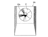
図5A~5Cは第2の実施形態に係る水力発電装置用集水装置5Aの図である。図5Aはこの集水装置5Aの正面図、図5Bは同集水装置5Aの側面図、図5Cは同集水装置5Aの斜視図である。図6A,図6Bは前記集水装置5Aと水車翼2との位置関係を示す図である。
この集水装置5Aでは、集水板12の外周縁部から上流側に延びる矩形枠状の枠部材18が取り付けられている。枠部材18における両側壁部18a,18aは、上流側に向かって幅広となる方向に傾斜している。また、枠部材18における下側壁部18bは、上流側に向って下方向に傾斜している。
さらに、集水板12の下流側の面のうち、通水孔12aの周縁部から下流側に円筒状に延びる筒状部材(排出管部)14が取り付けられている。この筒状部材14は、水車翼2に干渉しない位置に配置される。このような枠部材18により通水孔12aの上流側に流水を効率良く集めることができる。また、筒状部材14により通水孔12aから出る水流の全てを水力発電装置の翼に効率良く当てることが可能となる。その他、前述の実施形態と同様の作用効果を奏する。
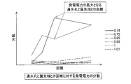
図7は、集水装置5Aにおいて、通水孔12aの直径が水車翼2の直径の0.95倍の例を示す正面図である。図8は、集水装置5Aにおいて、通水孔12aの直径が水車翼2の直径の0.75倍の例を示す正面図である。図9は、通水孔と翼先端との距離に対する発電電力の比較を示す図である。通水孔の直径が翼直径未満(グラフ中「1」未満の線)の場合と、通水孔の直径が翼直径以上(グラフ中「1」以上の線)の場合との、発電電力を比較している。通水孔径比(=通水孔直径/翼直径)が「0.75」の場合と「0.74」の場合とで発電電力に差はない。
図10は、通水孔と翼先端との距離に対する発電電力の分散を示す図である。通水孔径比(=通水孔直径/翼直径)が「1」に近い場合、発電電力の分散が小さい。すなわち、安定した発電電力が得られ、翼にかかる疲労荷重も小さく機械体への負荷も小さい。通水孔径比が「0.75」と「0.74」とは、発電電力の分散が大きく、通水孔径比「0.74」は発電電力が最大となる通水孔と翼先端との距離で分散が大きい。すなわち発電電力が安定せず、翼にかかる疲労荷重が大きくなり機械体への負担が大きい。
集水板12の通水孔12aは、丸孔だけに限定されるものではなく、例えば、楕円形であってもよい。また、通水孔12aの中心L1と水車翼2の回転中心L2とは、一致していなくてもよい。さらに、集水板ガイド13を省略し、集水板12を水路1に固定的に設置してもよい。枠部材18がある集水装置5Aにおいて、例えば、水路全体を遮断せずに流路途中に集水装置5Aを設置してもよい。枠部材18がある集水装置5Aにおいて、筒状部材14を省略することも可能である。
〔第3の実施形態〕
この発明の第3の実施形態を図11ないし図18と共に説明する。水力発電装置全体の概略構成、水力発電モジュール3、および集水装置5の集水板12の構成は、前述の第1の実施形態と同じであるから詳細な説明を省略する。なお、図11では、集水板12が、2点鎖線により示されている。
この発明の第3の実施形態を図11ないし図18と共に説明する。水力発電装置全体の概略構成、水力発電モジュール3、および集水装置5の集水板12の構成は、前述の第1の実施形態と同じであるから詳細な説明を省略する。なお、図11では、集水板12が、2点鎖線により示されている。
<支持部材について>
この実施形態の支持部材4も、第1の実施形態と同様に、図11に示す一対の固定具9,9と、水平支持材10と、発電機台11とを有する。固定具9,9は、水路1の両側壁1b,1bの上端付近から上端部に渡って設置されている。固定具9は、例えば、断面L形のアングルであり、その長手方向が水路1に沿って延びている。つまり、固定具9が、支持部材4における水路1の側壁1bに沿う部品を構成する。ただし、固定具9はこれに限定されない。一対の固定具9,9は、水路幅方向に対向するように両側壁1b,1bに固定されている。固定具9の水路1の側壁1bへの固定は、例えば、ボルト止めである。
この実施形態の支持部材4も、第1の実施形態と同様に、図11に示す一対の固定具9,9と、水平支持材10と、発電機台11とを有する。固定具9,9は、水路1の両側壁1b,1bの上端付近から上端部に渡って設置されている。固定具9は、例えば、断面L形のアングルであり、その長手方向が水路1に沿って延びている。つまり、固定具9が、支持部材4における水路1の側壁1bに沿う部品を構成する。ただし、固定具9はこれに限定されない。一対の固定具9,9は、水路幅方向に対向するように両側壁1b,1bに固定されている。固定具9の水路1の側壁1bへの固定は、例えば、ボルト止めである。
水平支持材10は、水路1の幅方向に延びる棒状部材であり、その両端が一対の固定具9,9に支持されている。つまり、水平支持材10は、一対の固定具9,9により水路1の両側壁面1bの上端間に掛け渡される。このように、水平支持材10が、支持部材4における水路1をまたぐ部材を構成する。この実施形態の水平支持材10は、横断面形状が四角形の角パイプである。ただし、水平支持材10は角パイプに限定されない。この実施形態では、水平支持材18は、図3の取付金具19を介して固定具16にボルト連結されている。ただし、水平支持材18の支持方法はこれに限定されない。
水平支持材10の長手方向(水路1の幅方向)の中間付近に発電機台11が固定され、この発電機台10に発電機6が支持されている。この実施形態では、発電機台11は水平支持材10に溶接により接合され、発電機6は発電機台11にボルト(図示せず)により着脱自在に取り付けられている。ただし、発電機6および発電機台11の取り付け方法はこれに限定されない。
<集水板ガイドについて>
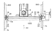
この実施形態の集水板ガイド13は、支持部材4の一部に固定されている。この実施形態では、集水板ガイド13は、支持部材4である水平支持材10に固定されている。詳細には、集水板ガイド13は、ガイド支持部品28を介して水平支持材10に固定されている。この実施形態では、ガイド支持部品28が水平支持材10に着脱自在にボルト連結され、集水板ガイド13がガイド支持部品28に着脱自在にボルト連結されている。
この実施形態の集水板ガイド13は、支持部材4の一部に固定されている。この実施形態では、集水板ガイド13は、支持部材4である水平支持材10に固定されている。詳細には、集水板ガイド13は、ガイド支持部品28を介して水平支持材10に固定されている。この実施形態では、ガイド支持部品28が水平支持材10に着脱自在にボルト連結され、集水板ガイド13がガイド支持部品28に着脱自在にボルト連結されている。
<可動機構について>
集水板ガイド13は、支持部材4に対して水の流れ方向に移動可能に固定されている。つまり、水力発電装置は、水の流れ方向に集水板ガイド13を移動可能とする可動機構30を備えている。以下に、この実施形態の可動機構30の詳細を述べる。
集水板ガイド13は、支持部材4に対して水の流れ方向に移動可能に固定されている。つまり、水力発電装置は、水の流れ方向に集水板ガイド13を移動可能とする可動機構30を備えている。以下に、この実施形態の可動機構30の詳細を述べる。
ガイド支持部品28は、水平支持材10の上面に取り付けられている。詳細には、ガイド支持部品28は、平板からなり、上下方向を向いた長円形の長孔32が形成されている。長孔32は、その長手方向が水の流れ方向に一致している。一方、水平支持材10の上面に、上方を向いたねじ孔34が形成されている。
つぎに、集水板ガイド13の水平支持材10への支持構造を説明する。水平支持材10の上面にガイド支持部品28を載置した状態で、ボルト36を上方から長孔32に挿通し、ねじ孔34に締め付ける。さらに、集水板ガイド13をガイド支持部品28にボルト(図示せず)により連結する。以上により、集水板ガイド13がガイド支持部品28を介して水平支持材10に支持される。なお、集水板ガイド13とガイド支持部品28の連結を、ガイド支持部品28の水平支持材10への連結よりも先に行ってもよい。
長孔32は、水の流れ方向A1に長手方向を有する長円形であるので、集水板ガイド13は支持部材4に対して水の流れ方向に移動可能、つまり、位置が変更可能に固定される。図13,14は、集水板ガイド13が支持部材4に対して水の流れ方向A1の下流側に固定された状態を示す。一方、図15,16は、集水板ガイド13が支持部材4に対して水の流れ方向A1の上流側に固定された状態を示す。このように、水平支持材10のねじ孔34、ガイド支持部品28の長孔32およびボルト36により、可動機構30が構成されている。
<水力発電装置の水路への設置手順について>
図17A~17Dを用いて、この実施形態の水力発電装置の水路1への設置手順を説明する。図17Aおよび図17Bに示すように、クレーン等を用いて、水力発電装置を上方から水路1へ設置する。水力発電装置が水路1へ設置された状態で(図17C)、ボルト、ナット(図示せず)のような締結手段により、固定具9,9を水路1の側壁1bに固定する。
図17A~17Dを用いて、この実施形態の水力発電装置の水路1への設置手順を説明する。図17Aおよび図17Bに示すように、クレーン等を用いて、水力発電装置を上方から水路1へ設置する。水力発電装置が水路1へ設置された状態で(図17C)、ボルト、ナット(図示せず)のような締結手段により、固定具9,9を水路1の側壁1bに固定する。
つづいて、図17Dに示す集水板12を水力発電装置に設置する。具体的には、上方から集水板ガイド13,13の案内溝13a,13a(図13)に集水板12の両側縁部を差し込む。これにより、集水板12が、集水板ガイド13,13により下方に案内される。以上により、水力発電装置が水路1に設置される。
<作用効果>
第3の実施形態の水力発電装置によれば、上述の第1および第2の実施形態と同様の作用効果を奏する。
第3の実施形態の水力発電装置によれば、上述の第1および第2の実施形態と同様の作用効果を奏する。
さらに、第3の実施形態によれば、集水装置5の固定に、水車翼2および発電機6の支持部材4を利用することで、集水装置5の設置を容易に行うことができる。さらに、集水板ガイド13を水路1の幅に合わせて固定することができるので、集水板12による集水効果を最大限に利用できる。特に、流量が少ない場合、無駄なく集水することで、発電機6の発電量を効率よく増加できる。
集水板ガイド13が、水路1をまたぐ部材である水平支持材10に固定されている。これにより、水路1の側壁1bに設置される集水板ガイド13を、水路1における水の流れ方向から見て、同一の位置に容易に設置できる。このため、設置作業が容易になる。
さらに、可動機構30により、集水板ガイド13が支持部材4の一つである水平支持材10に対して水の流れ方向A1に移動可能に支持されている。これにより、支持部材4と集水板ガイド13との間で、水の流れ方向A1に自由度を持たせることが可能となり、発電機6と集水板ガイド13間の水の流れ方向A1の距離を変えることができる。これにより、水量や流速に合わせて発電機6に対する最適な位置に集水板ガイド13および集水板12を設置でき、発電量を効率よく増加させることができる。
〔第4の実施形態〕
この発明の第4の実施形態を図18ないし図20と共に説明する。第4の実施形態において、第3の実施形態と同じ構成には同一の符号を付して説明を省略する。第3の実施形態では、支持部材4における水路1をまたぐ部材である水平支持材10に集水板ガイド13が固定されているのに対し、第4の実施形態では、支持部材4における水路1の側壁1bに沿う部品である固定具9に集水板ガイド13が固定されている。
この発明の第4の実施形態を図18ないし図20と共に説明する。第4の実施形態において、第3の実施形態と同じ構成には同一の符号を付して説明を省略する。第3の実施形態では、支持部材4における水路1をまたぐ部材である水平支持材10に集水板ガイド13が固定されているのに対し、第4の実施形態では、支持部材4における水路1の側壁1bに沿う部品である固定具9に集水板ガイド13が固定されている。
図18に示すように、集水板ガイド13は、ガイド支持部品40を介して固定具9に固定されている。この実施形態では、ガイド支持部品40が固定具9に着脱自在にボルト
連結され、集水板ガイド13がガイド支持部品40に着脱自在にボルト連結されている。
連結され、集水板ガイド13がガイド支持部品40に着脱自在にボルト連結されている。
<可動機構について>
図19に示すように、ガイド支持部品40は、固定具9の内側面(水路1を向く面)に取り付けられている。詳細には、ガイド支持部品40は、平板からなり、水平方向(水路1の幅方向)を向いた長円形の長孔42が形成されている。長孔42は、その長手方向が水の流れ方向A1に一致している。一方、固定具9に、水平方向(水路1の幅方向)を向いたねじ孔44が形成されている。
図19に示すように、ガイド支持部品40は、固定具9の内側面(水路1を向く面)に取り付けられている。詳細には、ガイド支持部品40は、平板からなり、水平方向(水路1の幅方向)を向いた長円形の長孔42が形成されている。長孔42は、その長手方向が水の流れ方向A1に一致している。一方、固定具9に、水平方向(水路1の幅方向)を向いたねじ孔44が形成されている。
つぎに、集水板ガイド13の固定具9への支持構造を説明する。固定具9の内側面にガイド支持部品40を当接させた状態で、ボルト46を水平方向(水路1の幅方向の内側)から長孔42に挿通し、ねじ孔44に締め付ける。さらに、集水板ガイド13をガイド支持部品40に連結する。集水板ガイド13のガイド支持部品40への連結は、ボルト連結であっても、溶接による接合であってもよい。以上により、集水板ガイド13がガイド支持部品40を介して固定具9に支持される。なお、集水板ガイド13とガイド支持部品40の連結を、ガイド支持部品40の固定具9への連結よりも先に行ってもよい。
長孔42は、水の流れ方向A1に長手方向を有する長円形であるので、集水板ガイド13は支持部材4に対して水の流れ方向に移動可能に固定される。図18は、集水板ガイド13が支持部材4に対して水の流れ方向A1の下流側に固定された状態を示している。一方、図20は、集水板ガイド13が支持部材4に対して水の流れ方向A1の上流側に固定された状態を示している。このように、固定具9のねじ孔44、ガイド支持部品40の長孔42およびボルト46により、可動機構50(図19)が構成されている。
第4の実施形態によっても、第3の実施形態と同様に、水流を集中させる集水装置5を水路1に容易に設置することができる。さらに、第4の実施形態によれば、水路1の側壁1bに沿う部品である固定具9に集水板ガイド13が固定されているので、水路1の側壁1bに集水板ガイド13を片側ずつ固定できる。これにより、水流のある水路1への設置時に、水の流れ方向の大きな負荷が集水板ガイド13にかかるのを軽減できる。
以上のとおり、図面を参照しながら好適な実施形態を説明したが、この発明は、以上の実施形態に限定されるものでなく、この発明の要旨を逸脱しない範囲内で、種々の追加、変更または削除が可能である。例えば、上述の第3および第4実施形態では、支持部材4およびガイド支持部品28(40)に可動機構30(50)が設けられていたが、可動機構30(50)は、支持部材4、集水板ガイド13およびガイド支持部品28(40)の少なくとも一つに設けられていればよい。したがって、そのようなものも本発明の範囲内に含まれる。
図11~図20の実施形態に係る発明には、通水孔を要件としない以下の態様1~5が含まれる。
[態様1]
態様1の水力発電装置は、水力を回転力に変換する翼車と、この翼車の回転により発電する発電機と、前記翼車の上流側に設置されて前記翼車に水路の水を集水する集水装置とを備えた水力発電装置であって、前記翼車および前記発電機は固定部品を介して前記水路に固定され、前記集水装置は、前記水路の水を増速して前記翼車に案内する集水板と、前記集水板を前記水路に設置する集水板ガイドとを有し、前記集水板ガイドは前記水路の側面に設置され、前記集水板ガイドが前記固定部品の一部に固定されて前記翼車に対して前記水路の上流側に配置されている。
態様1の水力発電装置は、水力を回転力に変換する翼車と、この翼車の回転により発電する発電機と、前記翼車の上流側に設置されて前記翼車に水路の水を集水する集水装置とを備えた水力発電装置であって、前記翼車および前記発電機は固定部品を介して前記水路に固定され、前記集水装置は、前記水路の水を増速して前記翼車に案内する集水板と、前記集水板を前記水路に設置する集水板ガイドとを有し、前記集水板ガイドは前記水路の側面に設置され、前記集水板ガイドが前記固定部品の一部に固定されて前記翼車に対して前記水路の上流側に配置されている。
態様1の構成によると、集水装置の固定に翼車および発電機の固定部品を利用することで、集水装置の設置を容易に行うことができる。また、集水板ガイドを水路の幅に合わせて固定することができるので、集水板による集水効果を最大限に利用できる。特に、流量が少ない場合、無駄なく集水することで、発電機の発電量を効率よく増加できる。
[態様2]
態様1において、前記固定部品は水路を跨ぐ部材を有しており、前記水路をまたぐ部材に、前記集水板ガイドが固定されていてもよい。この構成によれば、水路をまたぐ部材に集水板ガイドを固定することで、両側の水路側壁に設置される集水板ガイドを、水路の水の流れる方向で見て同一の位置に容易に設置できる。このため、設置作業が簡単になる。
態様1において、前記固定部品は水路を跨ぐ部材を有しており、前記水路をまたぐ部材に、前記集水板ガイドが固定されていてもよい。この構成によれば、水路をまたぐ部材に集水板ガイドを固定することで、両側の水路側壁に設置される集水板ガイドを、水路の水の流れる方向で見て同一の位置に容易に設置できる。このため、設置作業が簡単になる。
[態様3]
態様1において、前記固定部品は水路の側壁に沿う部品を有しており、前記水路の側壁に沿う部品に、前記集水板ガイドが固定されていてもよい。この構成によれば、水路の側壁に集水板ガイドを片側ずつ固定でき、水流のある水路への設置時に水の流れ方向にかかる集水板ガイドの負荷を軽減できる。
態様1において、前記固定部品は水路の側壁に沿う部品を有しており、前記水路の側壁に沿う部品に、前記集水板ガイドが固定されていてもよい。この構成によれば、水路の側壁に集水板ガイドを片側ずつ固定でき、水流のある水路への設置時に水の流れ方向にかかる集水板ガイドの負荷を軽減できる。
[態様4]
態様1から3のいずれか一つにおいて、さらに、水の流れ方向に前記集水板ガイドを移動可能とする可動機構を備え、前記固定部品、前記集水板ガイド、前記固定部品に前記集水板ガイドを支持する支持部品の少なくとも一つに、前記可動機構が設けられていてもよい。この構成によれば、固定部品と集水板ガイドとの間で、水の流れ方向に自由度を持たせることで、発電機と集水板ガイド間の水の流れ方向の距離を変えることができる。これにより、水量や流速に合わせて発電機に対する最適な位置に集水板ガイドおよび集水板を設置でき、発電量を効率よく増加させることができる。
態様1から3のいずれか一つにおいて、さらに、水の流れ方向に前記集水板ガイドを移動可能とする可動機構を備え、前記固定部品、前記集水板ガイド、前記固定部品に前記集水板ガイドを支持する支持部品の少なくとも一つに、前記可動機構が設けられていてもよい。この構成によれば、固定部品と集水板ガイドとの間で、水の流れ方向に自由度を持たせることで、発電機と集水板ガイド間の水の流れ方向の距離を変えることができる。これにより、水量や流速に合わせて発電機に対する最適な位置に集水板ガイドおよび集水板を設置でき、発電量を効率よく増加させることができる。
[態様5]
態様1から4のいずれか一つにおいて、前記集水板は、前記翼車に水の流れ方向に対向する通水孔を有してもよい。この構成によれば、流水の流路断面が通水孔の面積に狭められるので、翼車を通過する水の流速が増加する。これにより、発電効率の向上を図ることができる。
態様1から4のいずれか一つにおいて、前記集水板は、前記翼車に水の流れ方向に対向する通水孔を有してもよい。この構成によれば、流水の流路断面が通水孔の面積に狭められるので、翼車を通過する水の流速が増加する。これにより、発電効率の向上を図ることができる。
1…水路
2…水車翼
2ba…外周縁部
4…支持部材
5…集水装置
6…発電機
9 固定具(水路の側壁に沿う部品)
10 水平支持材(水路をまたぐ部材)
12…集水板
12a…通水孔
13 集水板ガイド
28,40 ガイド支持部品(支持部品)
30、50 可動機構
2…水車翼
2ba…外周縁部
4…支持部材
5…集水装置
6…発電機
9 固定具(水路の側壁に沿う部品)
10 水平支持材(水路をまたぐ部材)
12…集水板
12a…通水孔
13 集水板ガイド
28,40 ガイド支持部品(支持部品)
30、50 可動機構
Claims (9)
- 水路に浸かり水力を回転力に変換する水車翼と、この水車翼の回転により発電する発電機とを備えた水力発電装置に用いられ、前記水車翼の上流側に設置されて前記水車翼に前記水路の水を集水する水力発電装置用集水装置であって、
通水孔を有し前記水路の流水を前記通水孔に集める集水板を備え、この集水板の前記通水孔の面積が、前記水車翼の外周縁部を通る円の面積より小さい水力発電装置用集水装置。 - 請求項1に記載の水力発電装置用集水装置において、前記通水孔の形状が、前記集水板の正面視で円形である水力発電装置用集水装置。
- 請求項2に記載の水力発電装置用集水装置において、前記通水孔の中心と前記水車翼の回転中心とが一致している水力発電装置用集水装置。
- 請求項2または請求項3に記載の水力発電装置用集水装置において、前記通水孔の半径が、前記水車翼の回転半径の0.75倍~0.98倍である水力発電装置用集水装置。
- 前記水車翼と、前記発電機と、請求項1ないし請求項4のいずれか1項に記載の水力発電装置用集水装置とを備えた水力発電装置。
- 請求項5に記載の水力発電装置において、
前記水車翼および前記発電機は、支持部材を介して前記水路に固定され、
前記集水装置は、前記集水板を前記水路に設置する集水板ガイドを有し、
前記集水板ガイドは、前記水路の側面に設置され、
前記集水板ガイドが前記支持部材の一部に固定されて、前記水車翼に対して前記水路の上流側に配置されている水力発電装置。 - 請求項6に記載の水力発電装置において、前記支持部材は水路を跨ぐ部材を有しており、
前記水路をまたぐ部材に、前記集水板ガイドが固定されている水力発電装置。 - 請求項6に記載の水力発電装置において、前記支持部材は、水路の側壁に沿う部品を有しており、
前記水路の側壁に沿う部品に、前記集水板ガイドが固定されている水力発電装置。 - 請求項6から8のいずれか一項に記載の水力発電装置において、さらに、水の流れ方向に前記集水板ガイドを移動可能とする可動機構を備え、
前記支持部材、前記集水板ガイド、前記支持部材に前記集水板ガイドを支持する支持部品の少なくとも一つに、前記可動機構が設けられている水力発電装置。
Priority Applications (2)
| Application Number | Priority Date | Filing Date | Title |
|---|---|---|---|
| CN202080020867.7A CN113614358B (zh) | 2019-03-13 | 2020-03-03 | 水力发电装置用集水装置以及水力发电装置 |
| KR1020217032730A KR102766736B1 (ko) | 2019-03-13 | 2020-03-03 | 수력 발전 장치용 집수 장치 및 수력 발전 장치 |
Applications Claiming Priority (4)
| Application Number | Priority Date | Filing Date | Title |
|---|---|---|---|
| JP2019-045353 | 2019-03-13 | ||
| JP2019045353A JP2020148126A (ja) | 2019-03-13 | 2019-03-13 | 小水力発電装置の集水装置 |
| JP2019053409A JP7274895B2 (ja) | 2019-03-20 | 2019-03-20 | 水力発電装置用集水装置および水力発電装置 |
| JP2019-053409 | 2019-03-20 |
Publications (1)
| Publication Number | Publication Date |
|---|---|
| WO2020184273A1 true WO2020184273A1 (ja) | 2020-09-17 |
Family
ID=72427319
Family Applications (1)
| Application Number | Title | Priority Date | Filing Date |
|---|---|---|---|
| PCT/JP2020/008817 Ceased WO2020184273A1 (ja) | 2019-03-13 | 2020-03-03 | 水力発電装置用集水装置および水力発電装置 |
Country Status (3)
| Country | Link |
|---|---|
| KR (1) | KR102766736B1 (ja) |
| CN (1) | CN113614358B (ja) |
| WO (1) | WO2020184273A1 (ja) |
Cited By (1)
| Publication number | Priority date | Publication date | Assignee | Title |
|---|---|---|---|---|
| PL442675A1 (pl) * | 2022-10-28 | 2024-04-29 | Politechnika Rzeszowska im. Ignacego Łukasiewicza | Urządzenie, zwłaszcza do regulacji przepływu cieczy |
Citations (3)
| Publication number | Priority date | Publication date | Assignee | Title |
|---|---|---|---|---|
| KR20100131078A (ko) * | 2009-06-05 | 2010-12-15 | 하태안 | 부유식 수력발전기 |
| JP2014152645A (ja) * | 2013-02-05 | 2014-08-25 | Eneforest Kk | 水流発電装置 |
| JP2018076841A (ja) * | 2016-11-11 | 2018-05-17 | Ntn株式会社 | 軸流水車発電装置 |
Family Cites Families (5)
| Publication number | Priority date | Publication date | Assignee | Title |
|---|---|---|---|---|
| JP3136359B2 (ja) * | 1994-04-18 | 2001-02-19 | ハン ソル 康 | 流水力水車 |
| CN201396233Y (zh) * | 2009-01-05 | 2010-02-03 | 叶洪虎 | 高效水轮发电机 |
| US8651798B2 (en) * | 2009-02-12 | 2014-02-18 | Sheer Wind, Inc. | Kinetic hydropower generation system and intake therefore |
| AT508672B1 (de) * | 2010-02-11 | 2011-03-15 | Dieter Dipl Ing Muehlboeck | Vorrichtung und verfahren zum zurückhalten von schlacke am abstich eines metallurgischen gefässes |
| CN104595089B (zh) * | 2015-01-14 | 2017-02-08 | 黄河科技学院 | 一种水力发电用压力自适应水轮机桨叶 |
-
2020
- 2020-03-03 KR KR1020217032730A patent/KR102766736B1/ko active Active
- 2020-03-03 CN CN202080020867.7A patent/CN113614358B/zh active Active
- 2020-03-03 WO PCT/JP2020/008817 patent/WO2020184273A1/ja not_active Ceased
Patent Citations (3)
| Publication number | Priority date | Publication date | Assignee | Title |
|---|---|---|---|---|
| KR20100131078A (ko) * | 2009-06-05 | 2010-12-15 | 하태안 | 부유식 수력발전기 |
| JP2014152645A (ja) * | 2013-02-05 | 2014-08-25 | Eneforest Kk | 水流発電装置 |
| JP2018076841A (ja) * | 2016-11-11 | 2018-05-17 | Ntn株式会社 | 軸流水車発電装置 |
Cited By (1)
| Publication number | Priority date | Publication date | Assignee | Title |
|---|---|---|---|---|
| PL442675A1 (pl) * | 2022-10-28 | 2024-04-29 | Politechnika Rzeszowska im. Ignacego Łukasiewicza | Urządzenie, zwłaszcza do regulacji przepływu cieczy |
Also Published As
| Publication number | Publication date |
|---|---|
| CN113614358A (zh) | 2021-11-05 |
| KR20210137167A (ko) | 2021-11-17 |
| CN113614358B (zh) | 2023-11-17 |
| KR102766736B1 (ko) | 2025-02-11 |
Similar Documents
| Publication | Publication Date | Title |
|---|---|---|
| JP4787286B2 (ja) | 水力発電装置 | |
| JP4157590B1 (ja) | 簡易設置型流水式水力発電装置 | |
| JP7274895B2 (ja) | 水力発電装置用集水装置および水力発電装置 | |
| KR20110026069A (ko) | 풍과 수력을 이용한 전기 발전장치 | |
| CN113614358B (zh) | 水力发电装置用集水装置以及水力发电装置 | |
| JPWO2014054126A1 (ja) | 水車発電装置 | |
| KR102603342B1 (ko) | 수력 발전 장치 | |
| CN113646525B (zh) | 水力发电装置 | |
| KR101730529B1 (ko) | 회전날개 및 이를 포함하는 회전조립체, 그리고 수차날개 및 이를 포함하는 궤도수차 | |
| KR101314901B1 (ko) | 수력발전소용 터빈 | |
| JP2015031229A (ja) | 小水力発電装置 | |
| KR102616864B1 (ko) | 수력발전장치 | |
| KR20110021234A (ko) | 풍력 또는 수력발전기의 수직회전자 | |
| JP2018076841A (ja) | 軸流水車発電装置 | |
| JP2020148126A (ja) | 小水力発電装置の集水装置 | |
| JP2016145525A (ja) | 水力発電装置 | |
| JP2019173597A (ja) | 水車および小水力発電機 | |
| WO2021024888A1 (ja) | 水力発電装置用集水装置および水力発電装置 | |
| KR101320636B1 (ko) | 유수관용 수력발전장치 | |
| KR101243830B1 (ko) | 에너지집약장치를 갖는 항력형 수류수차 | |
| JP2020051267A (ja) | 水力発電装置 | |
| KR102827612B1 (ko) | 수로에 설치하는 수직형 소수력발전장치 | |
| JP5935114B2 (ja) | 発電装置 | |
| CN212027883U (zh) | 一种汽轮机叶片结构 | |
| KR20250096420A (ko) | 수력발전장치 |
Legal Events
| Date | Code | Title | Description |
|---|---|---|---|
| 121 | Ep: the epo has been informed by wipo that ep was designated in this application |
Ref document number: 20769116 Country of ref document: EP Kind code of ref document: A1 |
|
| NENP | Non-entry into the national phase |
Ref country code: DE |
|
| ENP | Entry into the national phase |
Ref document number: 20217032730 Country of ref document: KR Kind code of ref document: A |
|
| 122 | Ep: pct application non-entry in european phase |
Ref document number: 20769116 Country of ref document: EP Kind code of ref document: A1 |