WO2020184100A1 - ウェアラブルデバイスおよび制御方法 - Google Patents
ウェアラブルデバイスおよび制御方法 Download PDFInfo
- Publication number
- WO2020184100A1 WO2020184100A1 PCT/JP2020/006427 JP2020006427W WO2020184100A1 WO 2020184100 A1 WO2020184100 A1 WO 2020184100A1 JP 2020006427 W JP2020006427 W JP 2020006427W WO 2020184100 A1 WO2020184100 A1 WO 2020184100A1
- Authority
- WO
- WIPO (PCT)
- Prior art keywords
- image
- light
- projection
- detection
- control device
- Prior art date
- Legal status (The legal status is an assumption and is not a legal conclusion. Google has not performed a legal analysis and makes no representation as to the accuracy of the status listed.)
- Ceased
Links
Images












Classifications
-
- G—PHYSICS
- G03—PHOTOGRAPHY; CINEMATOGRAPHY; ANALOGOUS TECHNIQUES USING WAVES OTHER THAN OPTICAL WAVES; ELECTROGRAPHY; HOLOGRAPHY
- G03B—APPARATUS OR ARRANGEMENTS FOR TAKING PHOTOGRAPHS OR FOR PROJECTING OR VIEWING THEM; APPARATUS OR ARRANGEMENTS EMPLOYING ANALOGOUS TECHNIQUES USING WAVES OTHER THAN OPTICAL WAVES; ACCESSORIES THEREFOR
- G03B21/00—Projectors or projection-type viewers; Accessories therefor
-
- G—PHYSICS
- G09—EDUCATION; CRYPTOGRAPHY; DISPLAY; ADVERTISING; SEALS
- G09G—ARRANGEMENTS OR CIRCUITS FOR CONTROL OF INDICATING DEVICES USING STATIC MEANS TO PRESENT VARIABLE INFORMATION
- G09G5/00—Control arrangements or circuits for visual indicators common to cathode-ray tube indicators and other visual indicators
-
- H—ELECTRICITY
- H04—ELECTRIC COMMUNICATION TECHNIQUE
- H04N—PICTORIAL COMMUNICATION, e.g. TELEVISION
- H04N5/00—Details of television systems
- H04N5/74—Projection arrangements for image reproduction, e.g. using eidophor
Definitions
- the present invention relates to a wearable device and a control method that support the work of an operator.
- Patent Document 1 includes work management including a wearable device including a lens that outputs various information and a camera that images a work site, and a server that stores mapping information that is image-processed so that the actual work site can be reproduced as an image.
- the system is disclosed.
- the wearable device forms an actual work site in the information space based on the mapping information transmitted from the server, and projects the work site formed in the information space so as to overlap the actual field of view through the lens.
- the server obtains information on the behavior of the worker based on the imaging information captured by the camera, and monitors the information on the behavior of the worker in the information space. According to the system of Patent Document 1, the movement of the worker can be monitored and managed by the camera of the wearable device, and the instruction to the worker can be displayed on the lens.
- Patent Document 2 a camera installed at a work site captures a destination label attached to a work object, and projects information on a sort destination based on the destination label onto the work object to support sorting work.
- the information processing device to be used is disclosed.
- an operator provides information indicating a sorting destination projected on a work object at a work site in the real world based on a destination label taken by a camera installed at the work site in the real world. It can be visually recognized.
- Patent Document 3 discloses an information input device including a projection unit that forms effective display information in an operation area and an imaging unit that acquires an operation content on the operation area.
- the projection unit of the apparatus of Patent Document 3 includes a spatial modulation element having display means divided into a plurality of display areas, and a light source including a plurality of light emitting units associated with each of the plurality of display areas.
- the projection unit of the apparatus of Patent Document 3 has a configuration in which display information formed based on the light applied to the display unit of the space modulation element is projected onto the operation area, and the projection unit can be miniaturized and reduced in power consumption. Therefore, it is suitable for wearable devices.
- Patent Document 4 discloses an operation input device that enables operation input by gestures.
- the device of Patent Document 4 detects a hand region in a captured image, and for each portion in the background region composed of regions other than the detected hand region, a light source exists based on the brightness and color of the portion. Set the light source abundance as an index showing the possibility of doing so.
- the detected hand region Based on the shape, it is determined whether or not the hand region in the captured image has a defect.
- the device of Patent Document 4 determines the movement of the hand based on the determination result of the defect of the hand region in the captured image and the information representing the detected hand region.
- Patent Document 5 discloses a method of trimming the content projected within the target range.
- a depth map for determining the distance to an object is created by using a visible light camera such as Kinect (registered trademark) and a depth camera.
- the shape of the object is determined by segmenting the projection target from the background in the depth map.
- a small wearable device that provides work support to the worker is realized by projecting information for supporting the work of the worker into the field of view of the worker. be able to.
- the worker's hand and the background cannot be separated, and accurate work support cannot be provided. ..
- the unnecessary feature points become noise, and it may not be possible to accurately extract the feature points to be extracted from the background.
- the background and the hand are separated by taking the difference between the background and the hand based on the brightness and the color. Therefore, if the method of Patent Document 4 is used, the feature can be extracted from the background that does not include the hand, so that the feature of the background is not difficult to be detected by the feature of the hand.
- the background and the hand since the background and the hand are separated based on the brightness and the color, when the background has the same brightness and color as the color of the hand, the background and the hand cannot be separated accurately. There is.
- the shape of the object is determined by segmenting the projection target from the background in the depth map created by using the depth camera. Therefore, by using the method of Patent Document 5, it is possible to distinguish regions that are difficult to distinguish by brightness and color. However, if a depth camera is mounted on a wearable device, the size of the device becomes large and the portability is lowered.
- An object of the present invention is to provide a wearable device that solves the above-mentioned problems, reliably extracts a position for displaying information for work support without using a large-scale device, and realizes appropriate work support. It is in.
- the wearable device includes an image pickup device that generates image data, a control device that acquires image data from the image pickup device and sets projection conditions based on the acquired image data, and a control device that sets projection conditions from the control device.
- a projection device that acquires and projects light according to the acquired projection conditions is provided, and the control device sets a first projection condition for projecting detection light that forms a predetermined pattern, and the detection light irradiates.
- the first image captured when the image is not captured and the second image captured when the detection light is irradiated are acquired, and the first image is obtained based on the state of a predetermined pattern detected from the second image.
- a region is set, a detection image is generated by removing at least the first region from the first image, an indicator light irradiation position is set based on the features extracted from the detection image, and the indicator light is applied to the indicator light irradiation position.
- Set the second projection condition for projection
- the control method of one aspect of the present invention is a wearable device including an image pickup device that generates image data, a control device that sets projection conditions based on the image data, and a projection device that projects light according to the projection conditions.
- the control device acquires a first image captured when the detection light is not irradiated and a second image captured when the detection light is irradiated, and the second image is obtained.
- a first region is set based on the state of a predetermined pattern detected from the image, a detection image in which at least the first region is excluded from the first image is generated, and an instruction is given based on the features extracted from the detection image.
- the light irradiation position is set, and the second projection condition for projecting the indicated light to the indicated light irradiation position is set.
- the present invention it is possible to provide a wearable device that reliably extracts a position for displaying information for work support and realizes appropriate work support without using a large-scale device.
- the wearable device of the present embodiment is a wearable device that projects an instruction light to support the work performed by the worker based on an image of the work target. The operator can recognize the next work by visually recognizing the projected indicator light.
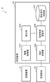
- FIG. 1 is a block diagram showing an outline of the configuration of the wearable device 1 according to the present embodiment.
- the wearable device 1 includes an image pickup device 11, a projection device 12, and a control device 13.
- the control device 13 is connected to the image pickup device 11 and the projection device 12.
- the image pickup device 11 is a camera having an image pickup function.
- the projection device 12 is a projector having a projection function.
- the control device 13 (also called a controller) is a device that controls the image pickup device 11 and the projection device 12.
- the image pickup device 11 generates image data.
- the image pickup device 11 images a range including the work target according to the control of the control device 13.
- the image pickup device 11 outputs image data generated by capturing a range including a work target to the control device 13.
- the image pickup apparatus 11 is realized by a high-speed camera having a high shooting speed.
- the projection device 12 acquires the projection conditions from the control device 13.
- the projection device 12 projects light according to the acquired projection conditions.
- the projection device 12 projects the projected light according to the control of the control device 13.
- the projection device 12 projects detection light for detecting a working body such as a worker's hand or arm.
- the projection device 12 projects an instruction light indicating the position and instruction to the work target portion where the operator plans to perform the next work.
- the projection device 12 projects the detection light and the instruction light according to the control by the control device.
- the projection device 12 is realized by a projector using a spatial light modulation element.
- the control device 13 acquires image data from the image pickup device 11.
- the control device 13 sets the projection conditions based on the acquired image data.
- the control device 13 sets a first projection condition for projecting the detection light forming a predetermined pattern.
- the control device 13 acquires a first image captured when the detection light is not irradiated and a second image captured when the detection light is irradiated.
- the control device 13 sets the first region based on the state of a predetermined pattern detected from the second image.
- the control device 13 generates a detection image in which at least the first region is excluded from the first image.
- the control device 13 sets the indicated light irradiation position based on the features extracted from the detection image.
- the control device 13 sets a second projection condition for projecting the indicated light at the indicated light irradiation position.
- the control device 13 is realized by a microcomputer having a processor and a memory.
- the control device 13 controls the image pickup device 11 and the projection device 12 as in the following control example.
- the control device 13 generates a projection condition (also referred to as a first projection condition) for projecting the detection light forming a predetermined pattern, and outputs the generated first projection condition to the projection device 12.
- the control device 13 controls the image pickup device 11 to image a range including the work target.
- the control device 13 controls the image pickup device 11 and displays the image data (first image) in which the detection light is not displayed and the image data (second image) in which the detection light is displayed at continuous timings. Have an image taken.
- the control device 13 acquires the first image and the second image from the image pickup device 11, and detects the hands and arms of the operator from the acquired second image.
- control device 13 when the control device 13 detects the worker's hand or arm from the second image, the control device 13 generates a detection image by deleting the range of the worker's hand or arm from the first image. Next, the control device 13 detects the work target portion from the detection image. Then, the control device 13 generates a second projection condition for projecting the indicated light to the detected work target location, and outputs the generated second projection condition to the projection device 12.
- the above is an example of control of the image pickup device 11 and the projection device 12 by the control device 13.
- the wearable device 1 detects the indicated light irradiation position from the image data excluding the working body that performs the work on the work target. Therefore, it does not become difficult to detect the feature of the indicated light irradiation position due to the feature generated by the working body such as a hand or an arm. Therefore, according to the wearable device having the configuration of FIG. 1, the detection accuracy of the indicated light irradiation position is improved, so that highly accurate work support can be realized without deteriorating workability.
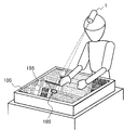
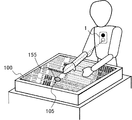
- FIGS. 2 to 4 are conceptual diagrams showing an application example of the wearable device 1 of the present embodiment.
- 2 and 3 are examples of arranging the wearable device 1 on the helmet worn by the operator.
- FIG. 4 shows an example in which the wearable device 1 is placed on the chest of the operator.
- the wearable device 1 verifies whether or not a part of the worker's body is reflected in the image data obtained by capturing the work target 100.
- the hands and arms of the worker are targeted for detection.
- the wearable device 1 projects a detection light 151 for detecting a hand or an arm toward the work target 100 (FIG. 2).
- the wearable device 1 projects a short pulsed detection light 151 so as not to be visually recognized by the operator.
- the detection light 151 is displayed in a striped pattern.
- the pattern of the detection light 151 is not limited to the stripe shape as long as the object located above the work target 100 can be detected.
- the interval between the stripes should be coarse until the worker's hand or arm is detected, and finer after the worker's hand or arm is detected.
- energy consumption can be reduced.
- the visibility of the detection light 151 depends on the ambient light.
- the visibility of the detection light 151 can be controlled by adjusting the contrast between the detection light 151 and the background and the brightness of the background. In the present embodiment, it is preferable that the detection light 151 is not visually recognized. Therefore, it is preferable to adjust the contrast between the detection light 151 and the background and the brightness of the background so that the detection light 151 is not easily visible.
- the wearable device 1 includes a high-speed camera capable of capturing the detection light 151 displayed under conditions that cannot be seen by the operator.
- the wearable device 1 images the work target 100 at a timing when the detection light 151 is not displayed. At this time, the wearable device 1 generates image data (also referred to as a first image) of the work target 100 that is not irradiated with the detection light 151. Further, the wearable device 1 images the work target 100 at the timing when the detection light 151 is displayed. At this time, the wearable device 1 generates image data (also referred to as a second image) of the work target 100 irradiated with the detection light 151.
- the wearable device 1 detects a portion (also referred to as a cutting point) where the detection light 151 is discontinuous from the image data (second image) on which the detection light 151 is displayed.
- a portion also referred to as a cutting point
- the wearable device 1 sets a region connecting the cutting points as the first region.
- the wearable device 1 expands the first region and sets the second region in order to surely hollow out the detected hand or arm of the worker.
- the wearable device 1 deletes the second region from the image data (first image) in which the detection light 151 is not displayed, and generates image data (also referred to as a detection image) that does not include the second region.
- the wearable device 1 detects a work target portion 105 on which the worker will perform the next work from the detection image (FIG. 3).
- the wearable device 1 When the wearable device 1 detects the work target location 105, it projects an indicator light 155 onto the detected work target location 105 (FIG. 3). The operator can recognize the position and contents of the next work by visually recognizing the instruction light 155 projected on the work target portion 105. For example, if the next work content of the operator is to connect a cable to the connector, the wearable device 1 sets the position of the connector at the work target portion 105 and irradiates the position with the indicator light 155. The operator can recognize the next work content by visually recognizing the position of the indicator light 155.
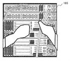
- FIG. 5 is a conceptual diagram showing an example of the detection image 165 used when the wearable device 1 detects the work target portion 105. Since the detection image 165 does not include the operator's hand or arm, the feature point formed by the operator's hand or arm is not included, and the feature point of the work target portion 105 is easily detected.
- noise is removed from the background feature points by removing the feature points formed by the operator's hands and arms.
- an example of extracting feature points from the background will be given at a stage after the hand or arm is detected.
- the hands and arms of the worker may block the position of the work target portion 105. If the work target portion 105 is hidden by the hand or arm at the time of activation, the wearable device 1 cannot detect the work target portion 105. However, if the worker's hand or arm moves, the wearable device 1 will eventually detect even the work target portion 105 that has been hidden by the hand or arm for a long time.
- the feature points can be extracted from most of the feature points in the background. Since it is desirable to extract as many feature points as possible, it is important to detect the work target portion 105 hidden by the hand or arm. Further, assuming that the work target portion 105 is hidden for a long time, a display indicating a warning when the work target portion 105 is not detected for a long time may be displayed on the surface of the work target 100. Good. In an actual work site, it is preferable to extract background feature points before the hand or arm is detected and continue to grasp the background feature points even if the hand or arm moves.
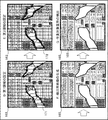
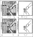
- FIG. 6 is a conceptual diagram showing a procedure in which the control device 13 detects a hand or arm from image data and sets a first region.
- the control device 13 acquires image data (first image 161) of the work target 100 not irradiated with the detection light 151 from the image pickup device 11 (A). Further, the control device 13 acquires image data (second image 162) of the work target 100 irradiated with the detection light 151 from the image pickup device 11 (B). The pattern of the detection light 151 is shown in the second image 162. The first image 161 and the second image 162 acquired by the control device 13 at this time are captured at continuous timings. The imaging order of the first image 161 and the second image 162 may be interchanged.
- the control device 13 When the control device 13 acquires the second image 162 (B), the control device 13 extracts the cutting point 170 of the detection light 151 (C). As shown in FIG. 6, when the hand or arm is shown in the second image 162, the hand or arm is closer to the image pickup device 11 than the background, so that the pattern of the detection light 151 applied to the hand or arm is displayed. It shifts. As a result, the cut point 170 appears in the pattern of the detection light 151 irradiated on the surface of the work target 100. The control device 13 connects a plurality of extracted cutting points 170 to set the first region 171 (D).
- FIG. 7 is a conceptual diagram showing a procedure from the control device 13 extracting the first region to detecting the work target portion 105.
- the control device 13 When the control device 13 sets the first area 171 (D), the control device 13 expands the first area 171 and sets the second area 172 (E). The control device 13 deletes the inside of the second region 172 from the first image 161 and generates image data (detection image 165) in which the inside of the first image 161 to the second region 172 is deleted (F). Since the first region 171 is an region connecting points on the contours of the hands and arms, if the inside of the first region 171 is deleted from the first image 161, a part of the hands and arms remains in the image data. This may make it difficult to extract features from the background work target 100. Therefore, the control device 13 sets a second area 172 that is an enlargement of the first area 171 and deletes the inside of the second area 172 from the first image 161.
- the control device 13 detects the work target portion 105 from the detection image 165 (G).
- the control device 13 detects the work target location 105, it generates a projection condition for projecting the indicator light 155 onto the work target portion 105, and outputs the generated projection condition to the projection device 12.
- the pattern displayed on the work target location 105 can be arbitrarily set according to the work situation, such as a figure indicating the work target portion 105 and symbols and characters indicating the work content.
- the image data obtained by deleting the inside of the first region 171 from the first image 161 is set in the detection image 165, and the feature is extracted from the background work target 100 using the detection image 165. May be good.
- the first area 171 is enlarged to set the second area, and the image data obtained by deleting the inside of the second area from the first image 161 is used. It may be set to the detection image 165.
- the second region 172 may be further enlarged and the enlarged second region may be deleted from the first image 161.
- FIG. 8 is a conceptual diagram for explaining an example of the operation timing of the image pickup device 11, the projection device 12, and the control device 13.
- the square box of FIG. 8 is for clarifying the relationship between the operation timings of the image pickup device 11, the projection device 12, and the control device 13.
- the control device 13 acquires image data from the image pickup device 11 at the timing of the box indicated by D.
- the control device 13 causes the projection device 12 to project the detection light 151 at the timing of the box indicated by P.
- the control device 13 causes the projection device 12 to project the indicator light 155 at the timing of the box indicated by M.
- the control device 13 acquires image data from the image pickup device 11.
- the detection light 151 is not shown in the image data (first image) acquired from the image pickup apparatus 11 at the timing T0.
- the control device 13 controls the projection device 12 to project the detection light 151 toward the work target 100 (P). Further, the control device 13 acquires image data from the image pickup device 11 (D). The detection light 151 is reflected in the image data (second image) acquired from the image pickup apparatus 11 at the timing T1.
- the control device 13 verifies whether or not the second image includes a hand or an arm.
- the hand or arm is not detected from the second image at the timing T2.
- the image pickup apparatus 11 is supposed to take an image at the timing T2, but the image pickup may be stopped.
- the control device 13 acquires image data from the image pickup device 11.
- the detection light 151 is not shown in the image data (first image) acquired from the image pickup apparatus 11 at the timing T3.
- the control device 13 controls the projection device 12 based on the projection conditions for projecting the detection light 151 on the work target 100, and projects the detection light 151 toward the work target 100 (P). Further, the control device 13 acquires image data from the image pickup device 11 (D). The detection light 151 is reflected in the image data (second image) acquired from the image pickup apparatus 11 at the timing T4.
- the control device 13 verifies whether or not the second image includes a hand or an arm.
- the hand or arm is detected from the second image at the timing T5.
- the image pickup apparatus 11 is supposed to take an image at the timing T5, but the image pickup may be stopped.
- the control device 13 At the timing T6, the control device 13 generates the detection image 165 using the second image.
- the control device 13 detects the work target portion 105 from the generated detection image 165.
- the control device 13 generates projection conditions for projecting the indicator light 155 onto the work target portion 105.
- the control device 13 controls the projection device 12 based on the projection conditions for projecting the indicator light 155 onto the work target portion 105, and projects the indicator light 155 toward the work target portion 105 (M). .. Further, the control device 13 acquires image data from the image pickup device 11. The indicator light 155 is reflected in the image data acquired from the image pickup apparatus 11 at the timing T7.
- the control device 13 controls the projection device 12 based on the projection conditions for projecting the indicator light 155 onto the work target portion 105, and projects the indicator light 155 (M). Further, the control device 13 acquires image data from the image pickup device 11. The indicator light 155 is reflected in the image data acquired from the image pickup apparatus 11 at the timing T8.
- the control device 13 controls the projection device 12 based on the projection conditions for projecting the detection light 151 on the work target 100, and projects the detection light 151 toward the work target 100 (P). Further, at the timing T9, the control device 13 controls the projection device 12 based on the projection conditions for projecting the indicator light 155 onto the work target portion 105, and projects the indicator light 155 toward the work target portion 105 ( M). Further, the control device 13 acquires image data from the image pickup device 11 (D). The detection light 151 and the indicator light 155 are reflected in the image data acquired from the image pickup apparatus 11 at the timing T8.
- the control device 13 repeats the processes shown in timings T0 to T9 according to the detection status of the hand or arm. For example, the control device 13 repeats the processing of timings T0 to T2 when the hand or arm is not detected, and repeats the processing of timings T3 to T9 when the hand or arm is detected.
- FIGS. 1 to 8 are examples, and the configuration, usage scene, processing, and the like of the wearable device 1 of the present embodiment are not limited to the same form and procedure.
- FIG. 9 is a block diagram showing the configuration of the image pickup apparatus 11.
- the image pickup device 11 includes an image pickup element 111, an image processing processor 113, an internal memory 115, and a data output circuit 117.
- the image pickup apparatus 11 is a camera capable of high-speed shooting, including the functions of a general digital camera.
- the image sensor 111 is an element for capturing an imaging range of the imaging device 11 and acquiring imaging data of the imaging range.
- the range including the work target 100 is set as the photographing range.
- the image pickup element 111 is a photoelectric conversion element in which semiconductor components are integrated into an integrated circuit.
- the image sensor 111 can be realized by, for example, a solid-state image sensor such as a CCD (Charge-Coupled Device) or a CMOS (Complementary Metal-Oxide-Semiconductor).
- the image pickup element 111 is composed of an element that captures light in the visible region, but may be composed of an element that can capture and detect electromagnetic waves such as infrared rays, ultraviolet rays, X-rays, gamma rays, radio waves, and microwaves.
- the image processing processor 113 executes image processing such as dark current correction, interpolation calculation, color space conversion, gamma correction, aberration correction, noise reduction, and image compression on the imaged data captured by the image sensor 111. It is an integrated circuit that converts to image data. If the image information is output without being processed, the image processing processor 113 may be omitted.
- the internal memory 115 is a storage element that temporarily stores image information that cannot be processed by the image processor 113 at one time and image information that has been processed.
- the image information captured by the image sensor 111 may be temporarily stored in the internal memory 115.
- the internal memory 115 may be configured by a general memory.
- the data output circuit 117 outputs the image data processed by the image processing processor 113 to the control device 13.
- FIG. 10 is a block diagram showing the configuration of the projection device 12 of the wearable device 1.
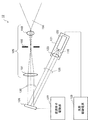
- FIG. 11 is a conceptual diagram showing a configuration example of the projection device 12.
- the projection device 12 includes an irradiation unit 121, a light source drive power supply 125, a spatial light modulation element 126, a modulation element drive unit 127, and a projection optical system 129.
- FIG. 10 is conceptual and does not accurately represent the positional relationship between each component, the light irradiation direction, and the like.
- the irradiation unit 121 emits coherent light 120 having a specific wavelength.
- the irradiation unit 121 includes a light source 122 and a collimating lens 123.
- the light 110 emitted by the irradiation unit 121 passes through the collimating lens 123 to become coherent light 120, and is incident on the display unit of the spatial light modulation element 126.
- the irradiation unit 121 includes a laser light source as the light source 122.
- the irradiation unit 121 is configured to emit light in the visible region.
- the irradiation unit 121 may be configured to emit light other than the visible region such as an infrared region or an ultraviolet region.
- the irradiation unit 121 may be configured by a light source other than a laser light source such as a light emitting diode, an incandescent light bulb, or a discharge tube.
- the irradiation unit 121 emits pulsed light.
- the irradiation unit 121 emits light with a pulse width that is difficult to see.
- the irradiation unit 121 emits light with a pulse width that is easily visible.
- the light source drive power supply 125 is a power supply that drives the light source 122 of the irradiation unit 121 according to the control of the control device 13 to emit light from the irradiation unit 121.
- the spatial light modulation element 126 displays a pattern (phase distribution of an image) for generating detection light 151 and instruction light 155 on its own display unit in accordance with the control of the modulation element drive unit 127.
- the display unit in a state where a predetermined pattern is displayed on the display unit of the spatial light modulation element 126, the display unit is irradiated with light 120.
- the spatial light modulation element 126 emits the reflected light (modulated light 130) of the incident light 120 toward the projection optical system 129.
- the incident angle of the light 120 is made non-perpendicular with respect to the display portion of the spatial light modulation element 126. That is, in the present embodiment, the emission axis of the light 120 from the irradiation unit 121 is slanted with respect to the display unit of the spatial light modulation element 126, and the light 120 is displayed on the display unit of the spatial light modulation element 126 without using a beam splitter. Is incident. Therefore, in the configuration of FIG. 11, since the light 120 is not attenuated by passing through the beam splitter, the utilization efficiency of the light 120 can be improved.
- the spatial light modulation element 126 can be realized by a phase modulation type spatial light modulation element that receives the incident of coherent light 120 having the same phase and modulates the phase of the incident light 120. Since the light emitted from the projection optical system 129 using the phase modulation type spatial light modulation element 126 is focus-free, it is necessary to change the focus for each projection distance even if the light is projected to a plurality of projection distances. There is no.
- the spatial light modulation element 126 may be an element of a type different from the phase modulation type as long as the display unit is divided into a plurality of display areas and display information can be displayed in each display area.
- the phase distribution of the detection light 151 and the indicator light 155 to be displayed on the surface of the work target 100 is displayed.
- the modulated light 130 reflected by the display unit of the spatial light modulation element 126 on which the phase distribution is displayed becomes an image as if a kind of diffraction grating formed an aggregate, so that the light diffracted by the diffraction grating gathers. An image is formed.
- the spatial light modulation element 126 is realized by, for example, a spatial light modulation element using a ferroelectric liquid crystal, a homogeneous liquid crystal, a vertically oriented liquid crystal, or the like.
- the spatial light modulation element 126 can be realized by LCOS (Liquid Crystal on Silicon).
- the spatial light modulation element 126 can be realized by a MEMS (Micro Electro Mechanical System).
- phase modulation type spatial light modulation element 126 energy can be concentrated on the image portion by operating so as to sequentially switch the locations where the projected light is projected. Therefore, if the phase modulation type spatial light modulation element 126 is used, the display information can be displayed brighter than those of other methods if the output of the light source is the same.
- the modulation element drive unit 127 causes the display unit of the spatial light modulation element 126 to display a pattern for generating an image to be displayed on the surface of the work target 100 according to the control of the control device 13.
- the modulation element driving unit 127 spatially photomodulates the parameters that determine the difference between the phase of the light 120 irradiated on the display unit of the spatial light modulation element 126 and the phase of the modulated light 130 reflected by the display unit. Drives element 126.
- the parameters that determine the difference between the phase of the light 120 irradiated to the display unit of the phase modulation type spatial light modulation element 126 and the phase of the modulated light 130 reflected by the display unit are, for example, the refractive index and the optical path length. It is a parameter related to optical characteristics.
- the modulation element driving unit 127 changes the refractive index of the display unit by changing the voltage applied to the display unit of the spatial light modulation element 126.
- the light 120 applied to the display unit is appropriately diffracted based on the refractive index of each portion of the display unit. That is, the phase distribution of the light 120 irradiated to the phase modulation type spatial light modulation element 126 is modulated according to the optical characteristics of the display unit.
- the method of driving the spatial light modulation element 126 by the modulation element drive unit 127 is not limited to the above.
- the projection optical system 129 projects the modulated light 130 modulated by the spatial light modulation element 126 as the projected light 150.
- the projection optical system 129 includes a Fourier transform lens 191, an aperture 192, and a projection lens 193.
- the modulated light 130 modulated by the spatial light modulation element 126 is irradiated as projected light 150 by the projection optical system 129.
- any of the components of the projection optical system 129 may be omitted.
- the Fourier transform lens 191 is an optical lens for forming an image formed when the modulated light 130 reflected by the display unit of the spatial light modulation element 126 is projected at infinity at a nearby focal point. In FIG. 11, the focal point is formed at the position of the aperture 192.
- the aperture 192 shields the higher-order light contained in the light focused by the Fourier transform lens 191 and specifies the range in which the projected light 150 is displayed.
- the opening of the aperture 192 is opened smaller than the outermost circumference of the display area at the position of the aperture 192, and is installed so as to block the peripheral area of the display information at the position of the aperture 192.
- the opening of the aperture 192 is formed in a rectangular or circular shape.
- the aperture 192 is preferably installed at the focal position of the Fourier transform lens 191 but may deviate from the focal position as long as it can exert a function of erasing higher-order light.
- the projection lens 193 is an optical lens that magnifies and projects the light focused by the Fourier transform lens 191.
- the projection lens 193 projects the projected light 150 so that the image corresponding to the phase distribution displayed on the display unit of the spatial light modulation element 126 is projected within the projection range.
- the wearable device 1 When the wearable device 1 is used for projecting a line drawing such as a simple symbol, the projected light 150 projected from the projection optical system 129 is not uniformly projected on each display area, but the characters constituting the display information. It is projected intensively on parts such as, symbols, and frames. In such a case, according to the wearable device 1, the amount of light emitted from the light 120 can be substantially reduced, so that the overall light output can be suppressed. That is, since the wearable device 1 can be composed of a small and low-power irradiation unit 121, the light source drive power supply 125 for driving the irradiation unit 121 can be reduced in output, and overall power consumption can be reduced.
- the color of the indicator light 155 can be changed by changing the wavelength of the light emitted from the irradiation unit 121. Further, by using the irradiation unit 121 that simultaneously emits light of different wavelengths, it is possible to display the indicator light 155 composed of a plurality of colors.
- FIG. 12 is a conceptual diagram showing a configuration example of a projection device 12-2 that realizes projection of a plurality of colors.
- the projection device 12-2 of FIG. 12 includes an irradiation unit 121-2 that emits light of a plurality of colors.
- the irradiation unit 121-2 includes a light source 122-1, a collimating lens 123-1, a mirror 124-1, a light source 122-2, a collimating lens 123-2, and a dichroic mirror 124-2.
- FIG. 12 shows an example in which two colors of light are emitted using two light sources (light source 122-1 and light source 122-2), but three or more colors of light are emitted using three or more light sources. It may be configured to emit light.
- the light source 122-1 emits light 110-1 having a first wavelength.
- the light 110-1 emitted from the light source 122-1 passes through the collimating lens 123-1 and becomes coherent light.
- the light that has passed through the collimating lens 123-1 is reflected by the reflecting surface of the mirror 124-1 and passes through the dichroic mirror 124-2.
- the light 120 that has passed through the dichroic mirror 124-2 travels toward the display portion of the spatial light modulation element 126.
- the light source 122-2 emits light 110-2 having a second wavelength.
- the light 110-2 emitted from the light source 122-2 passes through the collimating lens 123-2 and becomes coherent light.
- the light that has passed through the collimating lens 123-2 is reflected by the reflecting surface of the dichroic mirror 124-2.
- the light 120 reflected by the reflecting surface of the dichroic mirror 124-2 travels toward the display portion of the spatial light modulation element 126.
- the irradiation unit 121-2 emits light 120 emitted from at least one of the light source 122-1 and the light source 122-2 toward the display unit of the spatial light modulation element 126.
- the irradiation unit 121-2 switches and irradiates the light of the first wavelength from the light source 122-1 and the light of the second wavelength from the light source 122-2 according to the control of the control device 13. ..
- the irradiation unit 121-2 may simultaneously irradiate the light of the first wavelength from the light source 122-1 and the light of the second wavelength from the light source 122-2.
- images of different colors can be displayed. For example, if the work performed by the operator according to the indicated light 155 is correct, green light is emitted, and if it is incorrect, red light is emitted, so that the correctness of the work situation can be determined by different colors. It can also be recognized by a person. Further, for example, if the indicator light 155 is displayed in a place where the green light is hard to be visually recognized, it may be difficult for the operator to recognize the indicator light 155. In such a case, the color of the indicator light 155 may be switched to a color that is easily visible to the operator.
- the image pickup device 11 may have difficulty in detecting the detection light 151.
- the color of the detection light 151 may be switched to a color that is easily detected by the image pickup apparatus 11.
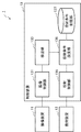
- FIG. 13 is a block diagram showing the configuration of the control device 13 of the wearable device 1.
- the control device 13 includes an image pickup control unit 131, a detection unit 133, a projection condition setting unit 136, a projection condition storage unit 137, and a projection control unit 139.
- the image pickup control unit 131 causes the image pickup device 11 to image a range including the work target 100, and acquires the image data captured by the image pickup device 11.
- the image pickup control unit 131 outputs the acquired image data to the detection unit 133.
- the detection unit 133 acquires image data from the image pickup control unit 131.
- the detection unit 133 acquires the image data (first image 161) of the work target 100 that is not irradiated with the detection light 151 and the image data (second image 162) of the work target 100 that is irradiated with the detection light 151. To do.
- the detection unit 133 detects the hand, arm, detection light 151, work target location 105, indicator light 155, etc. from the acquired image data.
- the detection unit 133 detects a part of the human body (hand or arm) that has entered the projection range or the work target portion 105 based on the features included in the image data.
- the detection unit 133 detects a part of the human body or the work target portion 105 based on features such as shape and color included in the acquired image data.
- the detection unit 133 may detect that the feature is caused by the human body.
- the detection unit 133 will give an example of detecting a hand or an arm based on a change in the pattern of the detection light 151 shown in the second image 162.
- the detection unit 133 When the detection unit 133 acquires the second image 162 in which the hand or arm is captured, the detection unit 133 extracts the cutting point 170 of the detection light 151 from the second image 162. The detection unit 133 connects the cutting points 170 and sets the first region 171. Further, the detection unit 133 expands the first region 171 to set the second region 172. The detection unit 133 generates image data (detection image 165) in which the inside of the second region 172 is deleted from the first image 161.
- the detection unit 133 detects the work target location 105 on which the worker plans to perform the next work from the detection image 165.
- the detection unit 133 extracts the position coordinates of the work target portion 105.
- the detection unit 133 outputs the position coordinates of the extracted work target portion 105 to the projection condition setting unit 136.
- the irradiation position of the indicator light 155 is corrected to the correct position if a series of processes from the projection of the detection light to the detection of the work target portion 105 are continued. Further, in order to further improve the accuracy of the irradiation position of the indicator light 155, when the detection unit 133 acquires the image data irradiated with the indicator light 155, the position where the indicator light 155 is displayed and the work target 100 It may be configured to verify whether or not the position of and matches. When a deviation between the position where the indicator light 155 is displayed and the position of the work target 100 is detected, the indication light can be corrected by correcting the irradiation position of the indicator light 155 according to the degree of the deviation. The accuracy of the irradiation position of 155 is improved.
- the projection condition setting unit 136 sets the projection conditions for projecting the detection light 151 and the indicator light 155.
- the projection conditions set by the projection condition setting unit 136 include a light source control condition and a modulation element control condition described later.
- the projection condition setting unit 136 outputs the set projection condition to the projection control unit 139.
- the projection condition setting unit 136 acquires a pattern corresponding to the image to be displayed on the surface of the work target 100 from the projection condition storage unit 137.
- the pattern corresponding to the information displayed on the surface of the work target 100 is a phase distribution.
- an example of using the phase modulation type spatial light modulation element 126 will be described.
- the projection condition setting unit 136 sets the timing of emitting light from the projection device 12 and the light source control condition for controlling the output of the emitted light.
- the light source control condition is a condition for controlling the timing at which the irradiation unit 121 included in the projection device 12 emits the light 120.
- the light source control condition may be stored in the projection condition storage unit 137.
- the projection condition setting unit 136 sets the modulation element control conditions for controlling the image to be displayed on the surface of the work target 100.
- the modulation element control conditions correspond to the conditions for displaying the pattern corresponding to the image displayed on the surface of the work target 100 on the display unit of the spatial light modulation element 126.
- the modulation element control conditions are stored in advance in the projection condition storage unit 137.
- the projected light 150 for displaying the image corresponding to the pattern is projected. Will be done.
- the projection condition setting unit 136 acquires a phase distribution for displaying the pattern of the detection light 151 from the projection condition storage unit 137 at the timing of irradiating the detection light 151.
- the projection condition setting unit 136 outputs the projection conditions including the acquired phase distribution, the irradiation position of the detection light 151, and the projection timing to the projection control unit 139.
- the projection time of the detection light 151 is preferably set to a short time so that the operator cannot see it.
- the projection condition setting unit 136 acquires the position coordinates of the work target location 105
- the projection condition setting unit 136 acquires the phase distribution for displaying the indicator light 155 on the work target location 105 from the projection condition storage unit 137.
- the projection condition setting unit 136 outputs the projection conditions including the acquired phase distribution, the irradiation position of the indicator light 155, and the projection timing to the projection control unit 139.
- the projection time of the indicator light 155 is set to a time that can be visually recognized by the operator.
- the projection condition storage unit 137 stores a pattern corresponding to the detection light 151 and a pattern corresponding to the indicator light 155.
- the projection condition storage unit 137 stores the phase distribution corresponding to the detection light 151 and the phase distribution corresponding to the instruction light 155.
- the projection condition storage unit 137 may store a pattern for displaying information such as figures, symbols, numbers, and characters on the surface of the work target 100.
- the projection condition storage unit 137 stores the light source control condition and the modulation element control condition included in the projection condition. Further, the projection condition storage unit 137 stores the order of work performed on the work target 100 and the position where the indicator light 155 is displayed.
- the projection control unit 139 acquires the projection condition from the projection condition setting unit 136.
- the projection control unit 139 controls the projection device 12 so as to project the projection light 150 onto the surface of the work target 100 according to the projection conditions set by the projection condition setting unit 136.
- the projection control unit 139 synchronizes the timing of displaying the pattern corresponding to the image to be displayed on the display unit of the spatial light modulation element 126 with the irradiation timing of the light emitted from the irradiation unit 121 of the projection device 12. As a result, an image corresponding to the pattern displayed on the display unit of the spatial light modulation element 126 is displayed on the surface of the work target 100.
- FIG. 14 is a flowchart for explaining the outline of the operation of the wearable device 1.
- the wearable device 1 will be described as the main body of operation.
- the wearable device 1 images the work target 100 without irradiating the detection light 151 (step S11). At this time, the wearable device 1 generates an image (first image) of the work target 100 that is not irradiated with the detection light 151.
- the wearable device 1 irradiates the detection light 151 to image the work target 100 (step S12). At this time, the wearable device 1 generates an image (second image) of the work target 100 irradiated with the detection light 151.
- the wearable device 1 verifies whether the second image includes the hand or arm (step S13). For example, the wearable device 1 determines that the second image includes a hand or an arm when the detection light 151 is changed.
- step S14 When a hand or arm is detected in the second image (Yes in step S13), the wearable device 1 executes the indicated light projection condition setting process (step S14).
- the instruction light projection condition setting process generates a detection image in which the hand or arm area detected from the second image is deleted from the first image, detects a work target portion from the detection image, and projects the instruction light. This is the process of setting conditions. The details of the indicated light projection condition setting process will be described later with reference to the flowchart of FIG.
- the process returns to step S11.
- step S14 the wearable device 1 projects the instruction light 155 to the detected work target portion (step S15).
- step S16 when continuing the process (Yes in step S16), the process returns to step S11.
- step S16 when the process is not continued (No in step S16), the process according to the flowchart of FIG. 14 is terminated.
- the process according to the flowchart of FIG. 14 is continued for a period in which the worker wearing the wearable device 1 continues the work.
- the process according to the flowchart of FIG. 14 may be terminated at the discretion of the operator, or may be terminated at the discretion of the administrator who gives an instruction to the operator. Further, the process according to the flowchart of FIG. 14 may be automatically terminated at a preset timing.
- the above is an explanation of the outline of the operation of the wearable device 1.
- the flowchart of FIG. 14 is an example, and the outline of the operation of the wearable device 1 is not limited to the procedure as it is.
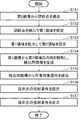
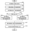
- FIG. 15 is a flowchart for explaining the instruction light projection condition setting process by the control device 13.
- the control device 13 will be described as the main body of operation.
- control device 13 extracts the cutting point 170 of the detection light 151 from the second image 162 (step S151).
- control device 13 connects the cutting points 170 and sets the first region 171 (step S152).
- control device 13 expands the first region 171 and sets the second region 172 (step S153).
- control device 13 deletes the inside of the second region 172 from the first image 161 and generates the detection image 165 (step S154).
- control device 13 detects the work target portion 105 from the detection image 165 (step S155).
- control device 13 generates a projection condition for projecting the indicated light on the projection device 12 (step S156).
- control device 13 outputs the generated projection condition to the projection device 12 (step S157).
- the above is the explanation of the instruction light projection condition setting process by the control device 13.
- the flowchart of FIG. 15 is an example, and the instruction light projection condition setting process by the control device 13 is not limited to the procedure as it is.
- the wearable device of the present embodiment includes an imaging device, a control device, and a projection device.
- the image pickup device generates image data.
- the control device acquires image data from the image pickup device and sets projection conditions based on the acquired image data of the work area.
- the projection device acquires projection conditions from the control device and projects light according to the acquired projection conditions.
- the control device sets a first projection condition for projecting the detection light forming a predetermined pattern.
- the control device acquires a first image captured when the detection light is not irradiated and a second image captured when the detection light is irradiated.
- the control device sets the first region based on the state of a predetermined pattern detected from the second image, and generates a detection image in which at least the first region is excluded from the first image.
- the control device sets the indicated light irradiation position based on the features extracted from the detection image, and sets the second projection condition for projecting the indicated light to the indicated light irradiation position.
- the control device sets a first projection condition for projecting the detection light that forms a striped pattern as a predetermined pattern.
- the control device acquires a second image captured when the detection light is irradiated according to the first projection condition, and connects discontinuous portions of the striped pattern detected from the acquired second image.
- the first area is set by.
- control device sets the first region by connecting discontinuous portions of a predetermined pattern detected in the second image, and at least the inside of the first region is excluded from the first image. Generates an image for detection. Further, in one aspect of the present embodiment, the control device generates a detection image by setting a second region in which the first region is enlarged and deleting the inside of the second region from the first image.
- the wearable device of the present embodiment since the indicated light irradiation position is detected from the image data excluding the working body that performs the work on the work target, the indicated light irradiation position is determined by the feature generated by the working body such as a hand or an arm. Features are not difficult to detect. Therefore, according to the wearable device of the present embodiment, the detection accuracy of the indicated light irradiation position is improved. That is, according to the wearable device of the present embodiment, it is possible to reliably extract the position where the information for work support is to be displayed and realize appropriate work support without using a large-scale device.
- the wearable device of the present embodiment is different from the first embodiment in that the indicated light is displayed on the palm detected by the irradiation of the detection light.
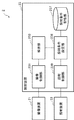
- FIG. 16 is a block diagram showing an example of the configuration of the wearable device 2 of the present embodiment.
- the wearable device 2 includes an image pickup device 21, a projection device 22, and a control device 23.
- the control device 23 is connected to the image pickup device 21 and the projection device 22. Since the configurations of the imaging device 21 and the projection device 22 are the same as those of the first embodiment, the configuration of the control device 23 will be described below.
- control device 23 includes an imaging control unit 231, a detection unit 233, a projection condition setting unit 236, a projection condition storage unit 237, and a projection control unit 239.
- the image pickup control unit 231 causes the image pickup device 21 to image a range including the work target, and acquires the image data captured by the image pickup device 21.
- the image pickup control unit 231 outputs the acquired image data to the detection unit 233.
- the detection unit 233 acquires image data from the image pickup control unit 231.
- the detection unit 233 acquires image data (first image) that is not irradiated with the detection light and image data (second image) that is irradiated with the detection light.
- the detection unit 233 detects the hand, arm, palm, work target location, detection light, indicator light, etc. from the acquired image data.
- the detection unit 233 detects a part (hand or arm) of the human body that has entered the projection range or a work target portion based on the features included in the image data.
- the detection unit 233 detects a part of the human body or a work target portion based on features such as shape and color included in the acquired image data.
- the detection unit 233 may consider that the feature is caused by the human body and detect it.
- the detection unit 233 will give an example of detecting a hand or an arm based on a change in the pattern of the detection light shown in the second image.
- the detection unit 233 When the detection unit 233 acquires the second image showing the hand or arm, the detection unit 233 extracts the cut point of the detection light from the second image. The detection unit 233 connects the cutting points to set the first region. Further, the detection unit 233 expands the first region and sets the second region. The detection unit 233 generates image data (detection image) in which the outside of the second region is deleted from the first image.
- the detection unit 233 detects the palm of the operator from the detection image.
- the detection unit 233 extracts the position coordinates of the palm.
- the detection unit 233 outputs the extracted position coordinates of the palm to the projection condition setting unit 236.
- the detection unit 233 detects the palm based on features such as the contour of the hand, the shape of the fingers, and wrinkles.
- the projection condition setting unit 236 sets the projection conditions for projecting the detection light and the indicated light.
- the projection conditions set by the projection condition setting unit 236 include a light source control condition and a modulation element control condition.
- the projection condition setting unit 236 outputs the set projection condition to the projection control unit 239.
- the projection condition setting unit 236 acquires a pattern corresponding to the image to be displayed on the surface of the work target from the projection condition storage unit 237.
- the pattern corresponding to the information displayed on the surface of the work target is the phase distribution.
- an example of using a phase modulation type spatial light modulation element will be described.
- the projection condition setting unit 236 sets the timing of emitting light from the projection device 22 and the light source control condition for controlling the output of the emitted light.
- the light source control condition is a condition for controlling the timing at which the irradiation unit (not shown) included in the projection device 22 emits light.
- the light source control condition may be stored in the projection condition storage unit 237.
- the projection condition setting unit 236 sets the modulation element control conditions for controlling the image to be displayed on the surface of the work target or the palm of the hand.
- the modulation element control conditions correspond to the conditions for displaying the pattern corresponding to the image to be displayed on the surface of the work target or the palm on the display unit of the spatial light modulation element.
- the modulation element control conditions may be stored in the projection condition storage unit 237.
- the projection condition setting unit 236 acquires a phase distribution for displaying the detection light pattern from the projection condition storage unit 237 at the timing of irradiating the detection light.
- the projection condition setting unit 236 outputs the projection conditions including the acquired phase distribution, the irradiation position of the detected light, and the projection timing to the projection control unit 239.
- the projection time of the detection light is preferably set to a short time so that the operator cannot see it.
- the projection condition setting unit 236 acquires the position coordinates of the palm
- the projection condition storage unit 237 acquires the phase distribution for displaying the indicated light on the palm.
- the projection condition setting unit 236 outputs the projection conditions including the acquired phase distribution, the irradiation position of the indicated light, and the projection timing to the projection control unit 239.
- the indicator light is set at a time that the operator can see.
- the projection condition storage unit 237 stores a pattern corresponding to the detected light and a pattern corresponding to the indicated light.
- the projection condition storage unit 237 stores the phase distribution corresponding to the detected light and the phase distribution corresponding to the indicated light. Further, the projection condition storage unit 237 may store a pattern for displaying information such as figures, symbols, numbers, and characters on the palm of the hand. Further, the projection condition storage unit 237 stores the light source control condition and the modulation element control condition included in the projection condition.
- the projection control unit 239 acquires the projection condition from the projection condition setting unit 236.
- the projection control unit 239 controls the projection device 22 so as to project the projection light onto the palm of the hand according to the projection conditions set by the projection condition setting unit 236.
- the projection control unit 239 synchronizes the timing of displaying the pattern corresponding to the image to be displayed on the display unit of the spatial light modulation element with the irradiation timing of the light emitted from the irradiation unit (not shown) of the projection device 22. As a result, an image corresponding to the pattern displayed on the display unit of the spatial light modulation element is displayed on the palm.
- FIG. 16 is an example, and the configuration of the control device 23 of the present embodiment is not limited to the same form and procedure.
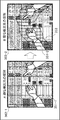
- FIG. 17 is a conceptual diagram showing a procedure in which the control device 23 detects a hand from the image data and sets the first region.
- the control device 23 acquires image data (first image 261) not irradiated with the detection light 251 from the image pickup device 21 (A). Further, the control device 23 acquires the image data (second image 262) irradiated with the detection light 251 from the image pickup device 21 (B). The second image 262 shows the pattern of the detection light 251 (vertical stripes). The first image 261 and the second image 262 acquired by the control device 23 at this time are captured at continuous timings. The imaging order of the first image 261 and the second image 262 may be interchanged.
- the control device 23 acquires the second image 262 (B), the control device 23 extracts the cutting point 270 of the detection light 251 (C).
- the pattern of the detection light 251 applied to the hand or arm is shifted because the hand or arm is closer to the image pickup device 21 than the background.
- the cut point 270 appears in the vertical stripes of the detection light 251 irradiated on the background.
- a plurality of cutting points 270 appear.
- the control device 23 connects a plurality of extracted cutting points 270 to set the first region 271 (D).
- FIG. 18 is a conceptual diagram showing a procedure in which the control device 23 extracts the contour of the hand and detects the palm as the indicated light irradiation area 205.
- the control device 23 When the control device 23 sets the first area 271 (D), the control device 23 expands the first area 271 and sets the second area 272 (E).
- the control device 23 deletes the outside of the second region 272 from the first image 261 and generates image data (detection image 265) in which the outside of the first image 261 to the second region 272 is deleted (F). Since the first region 271 is an region connecting points on the contour of the hand, if the outside of the first region 271 is deleted from the first image 261, a part of the hand is deleted from the image data, and the hand It becomes difficult to extract features from the contour. Therefore, the second region 272, which is an enlarged version of the first region 271, is set, and the outside of the second region 272 is deleted from the first image 261. In the detection image 265, a part of the hand may be deleted as long as the indicated light irradiation region 205 can be detected.
- the control device 23 detects the indicated light irradiation region 205 from the detection image 265 (G).
- the control device 23 detects the indicated light irradiation area 205, it generates a projection condition for projecting the indicated light onto the indicated light irradiation area 205, and outputs the generated projection condition to the projection device 22.
- the pattern displayed in the indicated light irradiation area 205 can be arbitrarily set according to the work situation, such as figures, symbols, and characters indicating work instructions.
- FIGS. 16 to 18 are examples, and the configuration and processing of the wearable device 1 of the present embodiment are not limited to the same form and procedure.
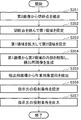
- FIG. 19 is a flowchart for explaining the instruction light projection condition setting process by the control device 23.
- the control device 23 will be described as the main body of operation.
- control device 23 extracts the cutting point 270 of the detection light 251 from the second image 262 (step S251).
- control device 23 connects the cutting points 270 and sets the first region 271 (step S252).
- control device 23 expands the first region 271 and sets the second region 272 (step S253).
- the control device 23 when the irradiation target is a hand (Yes in step S254), the control device 23 generates a detection image 265 by deleting the outside of the second region 272 (step S255). For example, when the control device 23 detects that the palm is facing upward, it determines that the irradiation target is the hand and performs the process of step S255.
- the control device 23 when the irradiation target is the background (work target location) (No in step S254), the control device 23 generates the detection image 265 by deleting the inside of the second region (step S256). For example, when the control device 23 detects that the palm is facing downward, it determines that the irradiation target is the work target portion and performs the process of step S256.
- the control device 23 detects the indicated light irradiation region 205 from the detection image 265 (step S257).
- the irradiation target is the palm (No in step S254)
- the indicated light irradiation area 205 is set to the palm.
- the irradiation target is a work target location (No in step S254)
- the indicated light irradiation region 205 is set as the background (work target location).
- control device 23 generates a projection condition for projecting the indicated light on the projection device 22, and outputs the generated projection condition to the projection device 22 (step S258).
- the above is the explanation of the instruction light projection condition setting process by the control device 23.
- the flowchart of FIG. 19 is an example, and the instruction light projection condition setting process is not limited to the procedure as it is.
- the first region is formed by connecting the discontinuous portions of the predetermined pattern detected in the second image, and at least the outside of the first region is excluded from the first image.
- an image for detection is generated.
- the detection image is generated by enlarging the first region to set the second region and removing the outside of the second region from the first image.
- a working body such as a hand or an arm extracted from the detection image is set at the indicated light irradiation position, and the indicated light is irradiated toward the indicated light irradiation position.
- the wearable device of the present embodiment by removing the background from the image data obtained by capturing the work object, it becomes easy to extract the features from the work body. Therefore, according to the wearable device of the present embodiment, the detection accuracy of the indicated light irradiation position is improved. That is, according to the wearable device of the present embodiment, it is possible to reliably extract the position where the information for work support is to be displayed and realize appropriate work support without using a large-scale device.
- the wearable device of the present embodiment irradiates low-density detection light until the operator's hand or arm is detected, and when the hand or arm is detected, narrows the irradiation range and irradiates high-density detection light. It differs from the first embodiment in that it does.
- FIG. 20 is a block diagram showing an example of the configuration of the wearable device 3 of the present embodiment.
- the wearable device 3 includes an image pickup device 31, a projection device 32, and a control device 33. Since the configurations of the imaging device 31 and the projection device 32 are the same as those of the first embodiment, the configuration of the control device 33 will be described below.
- the control device 33 includes an imaging control unit 331, a detection unit 333, an estimation unit 334, a phase distribution conversion unit 335, a projection condition setting unit 336, a projection condition storage unit 337, and a projection control unit 339.
- the image pickup control unit 331 causes the image pickup device 31 to image a range including the work target, and acquires the image data captured by the image pickup device 31.
- the image pickup control unit 331 outputs the acquired image data to the detection unit 333.
- the detection unit 333 acquires image data from the image pickup control unit 331.
- the detection unit 333 acquires image data (first image) that is not irradiated with the detection light and image data (second image) that is irradiated with the detection light.
- the detection unit 333 detects the hand, arm, work target location, detection light, instruction light, etc. from the acquired image data.
- the detection unit 333 detects a part of the human body (hand or arm) that has entered the projection range or a work target portion based on the features included in the image data. For example, the detection unit 333 detects a part of the human body or a work target portion based on features such as shape and color included in the acquired image data. Further, when the detection unit 333 detects a feature that has not been captured in the acquired image data, the detection unit 333 may consider that the feature is caused by the human body and detect it. In the present embodiment, the detection unit 333 will give an example of detecting a hand or an arm based on a change in the pattern of the detection light shown in the second image.
- the detection unit 333 When the detection unit 333 acquires the second image in which the hand or arm is captured, the detection unit 333 extracts the cut point of the detection light from the second image. The detection unit 333 connects the cutting points to set the first region. Further, the detection unit 333 expands the first region and sets the second region. The detection unit 333 generates image data (detection image) in which the inside of the second region is deleted from the first image.
- the detection unit 333 when the detection unit 333 acquires the second image showing the hand or arm, it outputs information for estimating the movement of the hand or arm (also referred to as estimation auxiliary information) to the estimation unit 334. For example, the detection unit 333 outputs the extracted cut point to the estimation unit 334 in association with the imaging time.
- the detection unit 333 detects the work target portion where the worker plans to perform the next work from the detection image.
- the detection unit 333 extracts the position coordinates of the work target portion.
- the detection unit 333 outputs the position coordinates of the extracted work target portion to the projection condition setting unit 336.
- the estimation unit 334 acquires estimation auxiliary information for estimating the movement of the hand from the detection unit 333.
- the estimation unit 334 estimates the movement of the worker's hand based on the acquired estimation auxiliary information, and sets the irradiation range of the detection light to be projected next time.
- the estimation unit 334 outputs the irradiation range of the set detection light to the phase distribution conversion unit 335.
- the estimation unit 334 acquires the coordinates of the cutting point associated with the imaging time from the detection unit 333 as estimation auxiliary information.
- the estimation unit 334 compares the movement states of a plurality of cutting points extracted from the second image captured during the period up to the projection timing of the detected light this time. Then, the estimation unit 334 sets the irradiation range at the next projection timing of the detection light based on the movement state of the cutting point.
- the estimation unit 334 estimates the position of the hand at the next detection light projection timing based on the moving speed and position of each of the plurality of cut points extracted during the period up to the current detection light projection timing. To do. As an example, the estimation unit 334 is based on the moving speed and position of a characteristic portion such as the center of gravity of the first region connecting a plurality of cut points extracted during the period up to the projection timing of the detected light this time. Estimate the position of the hand at the projection timing of the detected light.
- the method of estimating the movement of the hand by the estimation unit 334 is not limited to the method described here as long as the position of the hand at the next projection timing of the detected light can be estimated.
- the phase distribution conversion unit 335 acquires the irradiation range of the detected light from the estimation unit 334. Further, the phase distribution conversion unit 335 acquires a phase distribution for projecting a high-density pattern (dense detection light) from the projection condition storage unit 337. The phase distribution conversion unit 335 converts the phase distribution acquired from the projection condition storage unit 337 into a phase distribution for displaying a high-density pattern in the irradiation range of the detection light acquired from the estimation unit 334. The phase distribution conversion unit 335 outputs the converted phase distribution to the projection condition setting unit 336.
- the projection condition setting unit 336 sets the projection conditions for projecting the detection light and the indicated light.
- the projection conditions set by the projection condition setting unit 336 include a light source control condition and a modulation element control condition.
- the projection condition setting unit 336 outputs the set projection condition to the projection control unit 339.
- the projection condition setting unit 336 acquires a pattern corresponding to the image to be displayed on the surface of the work target from the projection condition storage unit 337.
- the pattern corresponding to the information displayed on the surface of the work target is the phase distribution.
- an example of using a phase modulation type spatial light modulation element will be described.
- the projection condition setting unit 336 sets the timing of emitting light from the projection device 32 and the light source control condition for controlling the output of the emitted light.
- the light source control condition is a condition for controlling the timing at which the irradiation unit (not shown) included in the projection device 32 emits light.
- the light source control conditions are stored in advance in the projection condition storage unit 337.
- the projection condition setting unit 336 sets the modulation element control conditions for controlling the image to be displayed on the work target surface.
- the modulation element control conditions correspond to the conditions for displaying the phase distribution corresponding to the image displayed on the surface of the work target on the display unit of the spatial light modulation element (not shown).
- the modulation element control conditions are stored in advance in the projection condition storage unit 337.
- the projection condition setting unit 336 acquires a phase distribution for displaying the pattern of the detection light from the projection condition storage unit 337 at the timing of irradiating the detection light. At the stage where the hand or arm is not detected, the projection condition setting unit 336 acquires a phase distribution for projecting a low-density pattern (sparse detection light) from the projection condition storage unit 337. On the other hand, when a hand or arm is detected, the projection condition setting unit 336 changes the phase distribution for projecting a high-density pattern (dense detection light) into the irradiation range set by the estimation unit 334. Obtained from 335.
- the projection condition setting unit 336 outputs the projection conditions including the acquired phase distribution, the irradiation position of the detected light, and the projection timing to the projection control unit 339.
- the projection time of the detection light is preferably set to a short time so that the operator cannot see it.
- the projection condition storage unit 337 acquires the phase distribution for displaying the indicated light at the work target location.
- the projection condition setting unit 336 outputs the projection conditions including the acquired phase distribution, the irradiation position of the indicated light, and the projection timing to the projection control unit 339. It is preferable that the indicator light is displayed for a longer time than the operator can visually recognize.
- the projection condition storage unit 337 stores a pattern corresponding to the detected light and a pattern corresponding to the indicated light.
- the pattern corresponding to the detection light includes a pattern corresponding to the sparse detection light (coarse pattern) and a pattern corresponding to the dense detection light (fine pattern).
- the projection condition storage unit 337 has a phase distribution corresponding to the sparse detection light (coarse pattern), a phase distribution corresponding to the dense detection light (fine pattern), and a phase corresponding to the indicated light. The distribution is memorized.
- the projection condition storage unit 337 may store a pattern for displaying information such as figures, symbols, numbers, and characters on the surface of the work target. Further, the projection condition storage unit 337 stores the light source control condition and the modulation element control condition included in the projection condition.
- the projection control unit 339 acquires the projection condition from the projection condition setting unit 336.
- the projection control unit 339 controls the projection device 32 so as to project the projection light onto the surface of the work target according to the projection conditions set by the projection condition setting unit 336.
- the projection control unit 339 synchronizes the timing of displaying the pattern corresponding to the image to be displayed on the display unit of the spatial light modulation element with the irradiation timing of the light emitted from the irradiation unit (not shown) of the projection device 32.
- FIG. 21 is a conceptual diagram for explaining an example of setting the irradiation range of the detection light.
- the projection device 32 irradiates the sparse detection light 351-1 toward the entire region.
- the second image 362-1 in which the coarse detection light 351-1 is displayed in the entire region is acquired (A).
- the projection device 32 irradiates the dense detection light 351-2 with the irradiation range 353 set at the projection timing of the second and subsequent detection lights.
- the second image 362-2 in which the dense detection light 351-2 is displayed inside the irradiation range 353 is acquired (B). If it becomes impossible to follow the movement of the hand at the second and subsequent projection timings of the detection light, the detection light 351-1 may be re-irradiated to the entire area.
- FIGS. 20 and 21 are examples, and the configuration of the control device 33 of the present embodiment is not limited to the same form and procedure.
- FIG. 22 is a flowchart for explaining the outline of the operation of the wearable device 3.
- the wearable device 3 will be described as the main body of operation.
- the wearable device 3 irradiates a sparse detection light to image a work target (step S31). At this time, the wearable device 3 generates an image (second image) of the work target irradiated with sparse detection light.
- the wearable device 3 verifies whether the second image includes the hand or arm (step S32). For example, the wearable device 3 determines that the second image includes a hand or an arm when a change is observed in the detected light.
- step S32 When a hand or arm is detected in the second image (Yes in step S32), a work target is imaged by irradiating a dense detection light (step S33). At this time, the wearable device 3 generates an image (second image) of the work target irradiated with the dense detection light. On the other hand, if the hand or arm is not detected in the second image (No in step S32), the process returns to step S31.
- the wearable device 3 images the work target without irradiating the detection light (step S34). At this time, the wearable device 3 generates an image (first image) of the work target that is not irradiated with the detection light.
- the instruction light projection condition setting process generates a detection image in which the hand or arm area detected from the second image is deleted from the first image, detects a work target portion from the detection image, and projects the instruction light. This is the process of setting conditions. The details of the indicated light projection condition setting process will be described later with reference to the flowchart of FIG. 23.
- step S35 the wearable device 3 projects the instruction light to the detected work target portion (step S36).
- the wearable device 3 executes the detection light projection condition setting process (step S37).
- the detection light projection condition setting process includes a process of setting the irradiation range of the detection light according to the detected movement of the hand or arm.
- step S38 when continuing the process (Yes in step S38), the process returns to step S33.
- step S38 the process according to the flowchart of FIG. 22 is terminated.
- the process according to the flowchart of FIG. 22 is continued for a period in which the worker wearing the wearable device 3 continues the work.
- the process according to the flowchart of FIG. 22 may be terminated at the discretion of the operator, or may be terminated at the discretion of the administrator who gives an instruction to the operator. Further, the process according to the flowchart of FIG. 22 may be automatically terminated at a preset timing.
- the above is an explanation of the outline of the operation of the wearable device 1.
- the flowchart of FIG. 22 is an example, and the outline of the operation of the wearable device 3 is not limited to the procedure as it is.
- FIG. 23 is a flowchart for explaining the instruction light projection condition setting process by the control device 33.
- the control device 33 will be described as the main body of operation.
- control device 33 extracts the cut point of the detected light from the second image (step S351).
- control device 33 connects the cutting points and sets the first region (step S352).
- control device 33 expands the first region and sets the second region (step S353).
- control device 33 generates a detection image by deleting the inside of the second region (step S354).
- control device 33 detects the work target area from the detection image (step S355).
- control device 33 generates a projection condition for projecting the indicated light on the projection device 32 (step S356).
- control device 33 outputs the generated projection condition to the projection device 32 (step S357).
- the above is the explanation of the instruction light projection condition setting process by the control device 33.
- the flowchart of FIG. 23 is an example, and the instruction light projection condition setting process by the control device 33 is not limited to the procedure as it is.
- FIG. 24 is a flowchart for explaining the detection light projection condition setting process by the control device 33.
- the control device 33 will be described as the main body of operation.
- the control device 33 estimates the detected movements of the hand and arm (step S371). For example, the control device 33 estimates the movement of the hand or arm based on the movement speed or position change of the cutting point.
- control device 33 sets the irradiation range of the detection light (step S373).
- control device 33 converts the phase distribution of the detected light into the phase distribution of the detected light for which the irradiation range is set (step S374).
- control device 33 generates a projection condition of the detection light for which the irradiation range is set (step S375).
- control device 33 when the movement of the hand or arm cannot be estimated (No in step S372), the control device 33 generates a projection condition of the detected light without setting the irradiation range (step S376).
- control device 33 outputs the set projection conditions to the projection device 32 (step S377).
- the above is the explanation of the detection light projection condition setting process by the control device 33.
- the flowchart of FIG. 24 is an example, and the detection light projection condition setting process is not limited to the procedure as it is.
- the wearable device of the present embodiment estimates the movement of the working body based on the feature detected from the second image, and sets and sets the irradiation range of the detected light according to the movement of the working body.
- a control device for adding the irradiation range of the detection light to the first projection condition is provided.
- the control device controls the projection device so as to project sparse detection light until the work body is detected, and controls the projection device so as to project dense detection light during the period when the work body is being detected. To do.
- the projection range of the projected light can be narrowed by setting the irradiation range of the detected light according to the movement of the working body, so that the power consumption can be reduced. Further, according to the wearable device of the present embodiment, the projection device is controlled so as to project sparse detection light until the work body is detected and to project dense detection light during the period when the work body is being detected. As a result, the power consumption until the working body is detected can be further reduced.
- the wearable device of the present embodiment is different from the first embodiment in that when the detection light is projected, the pulse width of the projected light is reduced to increase the output.
- FIG. 25 is a block diagram showing an example of the configuration of the wearable device 4 of the present embodiment.
- the wearable device 4 includes an image pickup device 41, a projection device 42, and a control device 43. Since the configurations of the imaging device 41 and the projection device 42 are the same as those of the first embodiment, the configuration of the control device 43 will be described below.
- control device 43 includes an image pickup control unit 431, a detection unit 433, a projection condition setting unit 436, a projection condition storage unit 437, and a projection control unit 439.
- the image pickup control unit 431 causes the image pickup device 41 to image a range including the work target, and acquires the image data captured by the image pickup device 41.
- the image pickup control unit 431 outputs the acquired image data to the detection unit 433.
- the detection unit 433 acquires image data from the image pickup control unit 431.
- the detection unit 433 acquires image data (first image) that is not irradiated with the detection light and image data (second image) that is irradiated with the detection light.
- the detection unit 433 detects the arm, hand, detection light, work target location, instruction light, etc. from the acquired image data.
- the detection unit 433 detects a part (hand or arm) of the human body that has entered the projection range or a work target portion based on the features included in the image data.
- the detection unit 433 detects a part of the human body or a work target portion based on features such as shape and color included in the acquired image data.
- the detection unit 433 may consider that the feature is caused by the human body and detect it.
- the detection unit 433 gives an example of detecting a hand or an arm based on a change in the pattern of the detection light shown in the second image.
- the detection unit 433 When the detection unit 433 acquires the second image showing the hand or arm, the detection unit 433 extracts the cut point of the detection light from the second image. The detection unit 433 connects the cutting points and sets the first region. Further, the detection unit 433 expands the first region and sets the second region. The detection unit 433 deletes the inside of the second region from the first image, and generates image data (detection image) in which the inside of the second region is deleted.
- the detection unit 433 detects the work target location where the worker plans to perform the next work from the detection image.
- the detection unit 433 extracts the position coordinates of the work target portion.
- the detection unit 433 outputs the position coordinates of the extracted work target portion to the projection condition setting unit 436.
- the projection condition setting unit 436 sets the projection conditions for projecting the detection light and the indicated light.
- the projection conditions set by the projection condition setting unit 436 include a light source control condition and a modulation element control condition.
- the projection condition setting unit 436 outputs the set projection condition to the projection control unit 439.
- the projection condition setting unit 436 acquires a pattern corresponding to the image to be displayed on the surface of the work target from the projection condition storage unit 437.
- the pattern corresponding to the information displayed on the surface of the work target is the phase distribution.
- an example of using a phase modulation type spatial light modulation element will be described.
- the projection condition setting unit 436 sets the timing of emitting light from the projection device 42 and the light source control condition for controlling the output of the emitted light.
- the light source control condition is a condition for controlling the timing at which the irradiation unit (not shown) included in the projection device 42 emits light.
- the light source control condition may be stored in the projection condition storage unit 437.
- the projection condition setting unit 436 sets the modulation element control conditions for controlling the image to be displayed on the work target surface.
- the modulation element control condition corresponds to a condition in which a pattern corresponding to an image to be displayed on the surface of a work target is displayed on a display unit of a spatial light modulation element (not shown).
- the modulation element control conditions may be stored in the projection condition storage unit 437.
- the projected light for displaying the information corresponding to the pattern on the surface of the work target is emitted. Be projected.
- the projection condition setting unit 436 acquires a phase distribution for displaying the detection light pattern on the work target from the projection condition storage unit 437 at the timing of irradiating the detection light.
- the projection condition setting unit 436 outputs the projection conditions including the acquired phase distribution, the irradiation position of the detected light, and the projection timing to the projection control unit 439.
- the projection condition setting unit 436 sets the light source control conditions so as to shorten the time for emitting the light from the projection device 42 and increase the output of the emitted light.
- the projection time of the detection light is preferably set to a short time so that the operator cannot see it.
- the projection condition storage unit 437 acquires the phase distribution for displaying the indicated light at the work target location.
- the projection condition setting unit 436 outputs the projection conditions including the acquired phase distribution, the irradiation position of the indicated light, and the projection timing to the projection control unit 439. It is preferable that the indicator light is displayed for a longer time than the operator can visually recognize.
- the projection condition storage unit 437 stores a pattern corresponding to the detected light and a pattern corresponding to the indicated light.
- the projection condition storage unit 437 stores the phase distribution corresponding to the detected light and the phase distribution corresponding to the indicated light. Further, the projection condition storage unit 437 may store a pattern for displaying information such as figures, symbols, numbers, and characters on the surface of the work target. Further, the projection condition storage unit 437 stores the light source control condition and the modulation element control condition included in the projection condition.
- the projection control unit 439 acquires the projection condition from the projection condition setting unit 436.
- the projection control unit 439 controls the projection device 42 so as to project the projection light onto the surface of the work target according to the projection conditions set by the projection condition setting unit 436.
- the projection control unit 439 synchronizes the timing of displaying the pattern corresponding to the image to be displayed on the display unit of the spatial light modulation element with the irradiation timing of the light emitted from the irradiation unit (not shown) of the projection device 42.
- the imaging control unit 431 and the projection control unit 439 are connected and the detection light is projected from the projection device 42, the imaging control unit 431 gives an instruction to increase the time during which the shutter of the imaging device 41 is open. It may be configured to output to 41.
- FIG. 26 is a conceptual diagram for explaining the relationship between the imaging timing of the imaging device 41 and the projection timing of the detection light of the projection device 42.
- the vertical axis of the timing chart of FIG. 26 is a guideline for the output of the detected light per unit time.
- the upper part (A) of FIG. 26 is an example of the relationship between the imaging timing of the imaging device 11 of the wearable device 1 and the projection timing of the detection light of the projection device 12 according to the first embodiment.
- the middle part (B) of FIG. 26 is an example of the relationship between the imaging timing of the wearable device 4 according to the present embodiment and the projection timing of the detection light of the projection device 42.
- the lower part (C) of FIG. 26 is another example of the relationship between the imaging timing of the wearable device 4 according to the present embodiment and the projection timing of the detection light of the projection device 42.
- the pulse width of the projected light from the projection device 42 is shortened and the pulse width of the projected light from the projection device 42 is shortened at the projection timing of the detection light from the projection device 42 as compared with the first embodiment. Increase the output of. If the emission time of the detection light is shortened and the output is increased, the contrast of the detection light is improved and the detection rate of the hand is improved.
- the shutter opening time of the imaging device 41 is shortened at the projection timing of the detected light from the projection device 42 as compared with the example of the middle stage (B). If the emission time of the detection light is shortened and the output is increased, the contrast of the detection light is improved, and if the detection rate of the hand is improved, the shutter opening time of the image pickup apparatus 41 can be shortened.
- FIGS. 25 and 26 are examples, and the configuration of the control device 43 of the present embodiment is not limited to the same form and procedure.
- the control device of the present embodiment adds a condition for shortening the pulse width of the detected light and increasing the output per unit time to the first projection condition.
- the detection accuracy of the detected light can be improved by increasing the output per unit time, so that the discontinuous portion of the predetermined pattern can be extracted with higher accuracy. Therefore, according to the present embodiment, the detectors such as the hand and the arm can be removed from the detection image with high accuracy, so that the work accuracy with higher accuracy than that of the first embodiment can be realized.
- the wearable device of the present embodiment is different from the first embodiment in that it includes a communication device that can be connected to an external system.
- FIG. 27 is a block diagram showing an example of the configuration of the wearable device 5 of the present embodiment.
- the wearable device 5 includes an image pickup device 51, a projection device 52, a control device 53, and a communication device 55.
- the control device 53 is connected to the projection device 52, the control device 53, and the communication device 55.
- the image pickup device 51 images a range including a work target according to the control of the control device 53.
- the image pickup device 51 outputs image data generated by capturing a range including a work target to the control device 53.
- the projection device 52 projects the projected light according to the control of the control device 53.
- the projection device 52 projects a detection light for detecting a worker's hand or arm. Further, the projection device 52 projects an instruction light indicating the position and the instruction to the work target portion where the operator plans to perform the next work.
- the control device 53 controls the image pickup device 51 and the projection device 52. Further, the control device 53 is connected to an external system (not shown) via the communication device 55.
- the control device 53 generates a projection condition (also referred to as a first projection condition) for projecting the detected light at a predetermined timing, and outputs the generated first projection condition to the projection device 52.
- the control device 53 controls the image pickup device 51 to image a range including the work target.
- the control device 53 controls the image pickup device 51 and causes the image data (first image) in which the detection light is not displayed and the image data (second image) in which the detection light is displayed to be imaged at continuous timings.
- the control device 53 acquires the first image and the second image from the image pickup device 51, and detects the hands and arms of the operator from the acquired second image.
- control device 53 When the control device 53 detects the worker's hand or arm from the second image, the control device 53 generates a detection image by deleting the range of the worker's hand or arm from the first image. The control device 53 detects the work target portion from the detection image. The control device 53 generates a projection condition (also referred to as a second projection condition) for projecting the indicated light to the detected work target location, and outputs the generated second projection condition to the projection device 52.
- a projection condition also referred to as a second projection condition
- the communication device 55 has a function of communicating with an external system by wired communication or wireless communication.
- the communication device 55 is realized by an input / output interface or a communication interface that enables connection with an information processing device, a mobile terminal, a display device, etc. (not shown) by wired communication or wireless communication.
- control device 53 controls the image pickup device 51 and the projection device 52 in response to an instruction from the external system. Further, for example, the control device 53 outputs the image data acquired from the image pickup device 51 to the external system. For example, if the first image, the second image, and the detection image are configured so that they can be confirmed in an external system, the work of the worker can be remotely monitored or instructions can be given to the worker remotely. It will be possible.
- the wearable device of the present embodiment includes a communication device for communicably connecting the external system and the control device.
- work support linked with an external system becomes possible.
- the work robot placed at the place where the work target is installed is controlled from a position different from the place where the work target is installed via an external system for work. It becomes possible to perform work using a robot.
- the information processing device 90 of FIG. 28 is a configuration example for executing the processing of the control device of each embodiment, and does not limit the scope of the present invention.
- the information processing device 90 includes a processor 91, a main storage device 92, an auxiliary storage device 93, an input / output interface 95, and a communication interface 96.
- the interface is abbreviated as I / F (Interface).
- the processor 91, the main storage device 92, the auxiliary storage device 93, the input / output interface 95, and the communication interface 96 are connected to each other via a bus 99 so as to be capable of data communication. Further, the processor 91, the main storage device 92, the auxiliary storage device 93, and the input / output interface 95 are connected to a network such as the Internet or an intranet via the communication interface 96.
- the processor 91 expands the program stored in the auxiliary storage device 93 or the like into the main storage device 92, and executes the expanded program.
- the software program installed in the information processing apparatus 90 may be used.
- the processor 91 executes the process by the control device according to the present embodiment.
- the main storage device 92 has an area in which the program is expanded.
- the main storage device 92 may be, for example, a volatile memory such as a DRAM (Dynamic Random Access Memory). Further, a non-volatile memory such as MRAM (Magnetoresistive Random Access Memory) may be configured / added as the main storage device 92.
- a volatile memory such as a DRAM (Dynamic Random Access Memory).
- a non-volatile memory such as MRAM (Magnetoresistive Random Access Memory) may be configured / added as the main storage device 92.
- the auxiliary storage device 93 stores various data.
- the auxiliary storage device 93 is composed of a local disk such as a hard disk or a flash memory. It is also possible to store various data in the main storage device 92 and omit the auxiliary storage device 93.
- the input / output interface 95 is an interface for connecting the information processing device 90 and peripheral devices.
- the communication interface 96 is an interface for connecting to an external system or device through a network such as the Internet or an intranet based on a standard or a specification.
- the input / output interface 95 and the communication interface 96 may be shared as an interface for connecting to an external device.
- the information processing device 90 may be configured to connect an input device such as a keyboard, mouse, or touch panel, if necessary. These input devices are used to input information and settings. When the touch panel is used as an input device, the display screen of the display device may also serve as the interface of the input device. Data communication between the processor 91 and the input device may be mediated by the input / output interface 95.
- the information processing device 90 may be equipped with a display device for displaying information.
- a display device it is preferable that the information processing device 90 is provided with a display control device (not shown) for controlling the display of the display device.
- the display device may be connected to the information processing device 90 via the input / output interface 95.
- the information processing device 90 may be provided with a disk drive, if necessary.
- the disk drive is connected to bus 99.
- the disk drive mediates between the processor 91 and a recording medium (program recording medium) (not shown), reading a data program from the recording medium, writing the processing result of the information processing apparatus 90 to the recording medium, and the like.
- the recording medium can be realized by, for example, an optical recording medium such as a CD (Compact Disc) or a DVD (Digital Versatile Disc).
- the recording medium may be realized by a semiconductor recording medium such as a USB (Universal Serial Bus) memory or an SD (Secure Digital) card, a magnetic recording medium such as a flexible disk, or another recording medium.
- USB Universal Serial Bus
- SD Secure Digital
- the above is an example of the hardware configuration for enabling the control device according to each embodiment of the present invention.
- the hardware configuration of FIG. 28 is an example of a hardware configuration for executing arithmetic processing of the control device according to each embodiment, and does not limit the scope of the present invention.
- the scope of the present invention also includes a program for causing a computer to execute a process related to the control device according to each embodiment.
- a program recording medium on which the program according to each embodiment is recorded is also included in the scope of the present invention.
- the components of the control device of each embodiment can be arbitrarily combined. Further, the components of the control device of each embodiment may be realized by software or by a circuit.
Landscapes
- Engineering & Computer Science (AREA)
- Physics & Mathematics (AREA)
- General Physics & Mathematics (AREA)
- Computer Hardware Design (AREA)
- Theoretical Computer Science (AREA)
- Multimedia (AREA)
- Signal Processing (AREA)
- Projection Apparatus (AREA)
- Transforming Electric Information Into Light Information (AREA)
- Controls And Circuits For Display Device (AREA)
- User Interface Of Digital Computer (AREA)
Abstract
作業性を低下することなく、高精度の作業支援を実現するウェアラブルデバイスを提供するために、画像データを生成する撮像装置と、画像データに基づいて投射条件を設定する制御装置と、投射条件に応じた光を投射する投射装置と、を備えるウェアラブルデバイスとする。制御装置は、所定の模様を形成する検出光を投射するための第1投射条件を設定し、検出光が照射されていないときに撮像された第1画像と、検出光が照射されているときに撮像された第2画像とを取得し、第2画像から検出される所定の模様の状態に基づいて第1領域を設定し、少なくとも第1領域を第1画像から除いた検出用画像を生成し、検出用画像から抽出される特徴に基づいて指示光照射位置を設定し、指示光照射位置に指示光を投射するための第2投射条件を設定する。
Description
本発明は、作業者の作業を支援するウェアラブルデバイスおよび制御方法に関する。
特許文献1には、各種情報を出力するレンズと作業現場を撮像するカメラとを備えるウェアラブルデバイスと、実際の作業現場を画像として再現可能に画像処理したマッピング情報を蓄積するサーバとを備える作業管理システムについて開示されている。ウェアラブルデバイスは、サーバから送信されたマッピング情報に基づいて実際の作業現場を情報空間内に形成するとともに、情報空間内に形成した作業現場をレンズ越しの実際の視野に重ねるように投影する。サーバは、カメラによって撮像された撮像情報に基づいて作業者の挙動に関する情報を得て、情報空間内における作業者の挙動に関する情報を監視する。特許文献1のシステムによれば、ウェアラブルデバイスのカメラで作業者の動きを監視・管理したり、作業者への指示をレンズに表示させたりすることができる。
特許文献2には、作業現場に設置されたカメラによって作業対象物に貼付された宛先ラベルを撮影し、宛先ラベルに基づいた仕分け先に関する情報をその作業対象物に投影することで仕分け作業を支援する情報処理装置について開示されている。特許文献2によれば、実世界の作業現場に設置されたカメラに撮影された宛先ラベルに基づいて、実世界の作業現場にある作業対象物に投影された仕分け先を示す情報を作業者が視認することができる。
特許文献3には、有効表示情報を操作領域に形成させる投射部と、操作領域上での操作内容を取得する撮像部と、を備える情報入力装置について開示されている。特許文献3の装置の投射部は、複数の表示領域に区分けされる表示手段を有する空間変調素子と、複数の表示領域のそれぞれに対応付けられた複数の発光部を含む光源とを有する。特許文献3の装置の投射部は、空間変調素子の表示部に照射された光を基に形成される表示情報を操作領域に投射する構成を有し、投影部を小型化かつ低電力化できるため、ウェアラブルデバイスに好適である。
特許文献4には、ジェスチャーによる操作入力を可能とする操作入力装置について開示されている。特許文献4の装置は、撮像画像中の手領域を検出し、検出された手領域以外の領域で構成される背景領域内の各部分について、当該部分の輝度や色彩に基づいて、光源が存在する可能性を示す指標としての光源存在度を設定する。特許文献4の装置は、光源存在度に基づいて、光源の影響を受けたと推定された領域と手領域とが予め定められた距離以内にあると判断された場合に、検出された手領域の形状に基づいて撮像画像中の手領域に欠損が生じているか判断する。特許文献4の装置は、撮像画像中の手領域の欠損の判断結果と、検出された手領域を表す情報とに基づいて、手の動作を判断する。
特許文献5には、ターゲットの範囲内に投影するコンテンツをトリミングする方法について開示されている。特許文献5の方法では、Kinect(登録商標)などの可視光カメラと深度カメラを用いて、オブジェクトまでの距離を決定するための深度マップが作成される。特許文献5の方法では、深度マップ内の背景から投影ターゲットをセグメント化することによってオブジェクトの形状を決定する。
特許文献1~3の手法を組み合わせれば、作業者の作業を支援するための情報をその作業者の視界に投射することで、作業者に対して作業支援を行う小型のウェアラブルデバイスを実現することができる。しかしながら、実際の作業現場においては、作業者の手と背景との相対的な位置関係が刻一刻と変わるため、作業者の手と背景とを分離できず、的確な作業支援を行うことができない。例えば、背景にある作業対象物に対して何らかの表示情報を表示させる場合、その作業対象物から特徴点を捕らえる必要がある。しかし、手の動きによって不要な特徴点が発生すると、その不要な特徴点がノイズとなり、背景から抽出したい特徴点を正確に抽出できないことがある。また、例えば、手の平に何らかの表示情報を表示させる場合、その手の平から特徴点を抽出する必要がある。しかし、背景が不要な特徴点を作ってしまうと、その不要な特徴点がノイズとなり、手の平から抽出したい特徴量を正確に抽出できないことがある。
特許文献4の手法では、輝度や色彩に基づいて背景と手との差分を取ることによって、背景と手とを分離する。そのため、特許文献4の手法を用いれば、手を含まない背景から特徴を抽出することができるため、背景の特徴が手の特徴によって検出されにくくなることがない。しかしながら、特許文献4の手法では、輝度や色彩に基づいて背景と手とを分離するため、背景に手の色と同じような輝度や色彩がある場合、背景と手とを精度よく分離できない場合がある。
特許文献5の手法では、深度カメラを用いて作成された深度マップ内の背景から投影ターゲットをセグメント化することによってオブジェクトの形状を決定する。そのため、特許文献5の手法を用いれば、輝度や色彩では判別の難しい領域を区別することができる。しかしながら、ウェアラブルデバイスに深度カメラを搭載すると装置が大型化してしまい、携帯性が低下する。
本発明の目的は、上述した課題を解決し、大掛かりな装置を用いずに、作業支援のための情報を表示させる位置を確実に抽出し、適切な作業支援を実現するウェアラブルデバイスを提供することにある。
本発明の一態様のウェアラブルデバイスは、画像データを生成する撮像装置と、画像データを撮像装置から取得し、取得した画像データに基づいて投射条件を設定する制御装置と、制御装置から投射条件を取得し、取得した投射条件に応じた光を投射する投射装置と、を備え、制御装置は、所定の模様を形成する検出光を投射するための第1投射条件を設定し、検出光が照射されていないときに撮像された第1画像と、検出光が照射されているときに撮像された第2画像とを取得し、第2画像から検出される所定の模様の状態に基づいて第1領域を設定し、少なくとも第1領域を第1画像から除いた検出用画像を生成し、検出用画像から抽出される特徴に基づいて指示光照射位置を設定し、指示光照射位置に指示光を投射するための第2投射条件を設定する。
本発明の一態様の制御方法は、画像データを生成する撮像装置と、画像データに基づいて投射条件を設定する制御装置と、投射条件に応じた光を投射する投射装置と、を備えるウェアラブルデバイスの制御方法であって、制御装置が、検出光が照射されていないときに撮像された第1画像と、検出光が照射されているときに撮像された第2画像とを取得し、第2画像から検出される所定の模様の状態に基づいて第1領域を設定し、少なくとも第1領域を第1画像から除いた検出用画像を生成し、検出用画像から抽出される特徴に基づいて指示光照射位置を設定し、指示光照射位置に指示光を投射するための第2投射条件を設定する。
本発明によれば、大掛かりな装置を用いずに、作業支援のための情報を表示させる位置を確実に抽出し、適切な作業支援を実現するウェアラブルデバイスを提供することが可能になる。
以下に、本発明を実施するための形態について図面を用いて説明する。ただし、以下に述べる実施形態には、本発明を実施するために技術的に好ましい限定がされているが、発明の範囲を以下に限定するものではない。なお、以下の実施形態の説明に用いる全図においては、特に理由がない限り、同様箇所には同一符号を付す。また、以下の実施形態において、同様の構成・動作に関しては繰り返しの説明を省略する場合がある。
(第1の実施形態)
まず、本発明の第1の実施形態に係るウェアラブルデバイスについて図面を参照しながら説明する。本実施形態のウェアラブルデバイスは、作業対象を撮影した画像に基づいて、作業者が行う作業を支援するための指示光を投射するウェアラブルデバイスである。作業者は、投射された指示光を視認することによって次の作業を認識できる。
まず、本発明の第1の実施形態に係るウェアラブルデバイスについて図面を参照しながら説明する。本実施形態のウェアラブルデバイスは、作業対象を撮影した画像に基づいて、作業者が行う作業を支援するための指示光を投射するウェアラブルデバイスである。作業者は、投射された指示光を視認することによって次の作業を認識できる。
(構成)
図1は、本実施形態に係るウェアラブルデバイス1の構成の概要を示すブロック図である。ウェアラブルデバイス1は、撮像装置11、投射装置12、および制御装置13を備える。制御装置13は、撮像装置11および投射装置12に接続される。例えば、撮像装置11は、撮像機能を有するカメラである。例えば、投射装置12は、投射機能を有するプロジェクタである。例えば、制御装置13(コントローラとも呼ぶ)は、撮像装置11および投射装置12を制御する装置である。
図1は、本実施形態に係るウェアラブルデバイス1の構成の概要を示すブロック図である。ウェアラブルデバイス1は、撮像装置11、投射装置12、および制御装置13を備える。制御装置13は、撮像装置11および投射装置12に接続される。例えば、撮像装置11は、撮像機能を有するカメラである。例えば、投射装置12は、投射機能を有するプロジェクタである。例えば、制御装置13(コントローラとも呼ぶ)は、撮像装置11および投射装置12を制御する装置である。
撮像装置11は、画像データを生成する。
例えば、撮像装置11は、制御装置13の制御に応じて、作業対象を含む範囲を撮像する。撮像装置11は、作業対象を含む範囲を撮像することで生成される画像データを制御装置13に出力する。例えば、撮像装置11は、撮影速度の速い高速カメラによって実現される。
投射装置12は、制御装置13から投射条件を取得する。投射装置12は、取得した前記投射条件に応じた光を投射する。
例えば、投射装置12は、制御装置13の制御に応じて投射光を投射する。例えば、投射装置12は、作業者の手や腕などの作業体を検出するための検出光を投射する。例えば、投射装置12は、作業者が次に作業を行う予定の作業対象箇所にその位置や指示を示す指示光を投射する。例えば、投射装置12は、制御装置による制御に応じて検出光や指示光を投射する。例えば、投射装置12は、空間光変調素子を用いたプロジェクタによって実現される。
制御装置13は、撮像装置11から画像データを取得する。制御装置13は、取得した画像データに基づいて投射条件を設定する。制御装置13は、所定の模様を形成する検出光を投射するための第1投射条件を設定する。制御装置13は、検出光が照射されていないときに撮像された第1画像と、検出光が照射されているときに撮像された第2画像とを取得する。制御装置13は、第2画像から検出される所定の模様の状態に基づいて第1領域を設定する。制御装置13は、少なくとも第1領域を第1画像から除いた検出用画像を生成する。制御装置13は、検出用画像から抽出される特徴に基づいて指示光照射位置を設定する。制御装置13は、指示光照射位置に指示光を投射するための第2投射条件を設定する。例えば、制御装置13は、プロセッサやメモリを有するマイクロコンピュータによって実現される。
例えば、制御装置13は、以下の制御例のように、撮像装置11および投射装置12を制御する。まず、制御装置13は、所定の模様を形成する検出光を投射するための投射条件(第1投射条件とも呼ぶ)を生成し、生成した第1投射条件を投射装置12に出力する。次に、制御装置13は、撮像装置11を制御し、作業対象を含む範囲を撮像させる。次に、制御装置13は、撮像装置11を制御し、検出光が表示されていない画像データ(第1画像)と、検出光が表示された画像データ(第2画像)とを連続したタイミングで撮像させる。次に、制御装置13は、撮像装置11から第1画像および第2画像を取得し、取得した第2画像から作業者の手や腕を検出する。次に、制御装置13は、作業者の手や腕を第2画像から検出すると、作業者の手や腕の範囲を第1画像から削除することによって検出用画像を生成する。次に、制御装置13は、検出用画像から作業対象箇所を検出する。そして、制御装置13は、検出した作業対象箇所に指示光を投射するための第2投射条件を生成し、生成した第2投射条件を投射装置12に出力する。以上が、制御装置13による、撮像装置11および投射装置12の制御例である。
上述の制御装置13の制御によれば、ウェアラブルデバイス1は、作業対象に対して作業を行う作業体を除いた画像データから指示光照射位置を検出する。そのため、手や腕などの作業体が生成する特徴によって指示光照射位置の特徴が検出されにくくなることがない。そのため、図1の構成のウェアラブルデバイスによれば、指示光照射位置の検出精度が向上するため、作業性を低下することなく、高精度の作業支援を実現できる。
図2~図4は、本実施形態のウェアラブルデバイス1の適用例を示す概念図である。図2および図3は、作業者の被るヘルメットにウェアラブルデバイス1を配置する例である。図4は、作業者の胸元にウェアラブルデバイス1を配置する例である。
ウェアラブルデバイス1は、作業対象100を撮像した画像データに作業者の体の一部が写っているか否かを検証する。本実施形態においては、作業者の手や腕を検出対象とする。ウェアラブルデバイス1は、手や腕を検出するための検出光151を作業対象100に向けて投射する(図2)。ウェアラブルデバイス1は、作業者に視認されないように、短パルス化した検出光151を投射する。図2の例では、検出光151は、ストライプ状の模様で表示される。なお、検出光151の模様は、作業対象100の上方に位置する物体を検出できさえすれば、ストライプ状に限定されない。また、ストライプ状の模様の検出光151を照射する場合、ストライプの間隔は、作業者の手や腕が検出されるまでは粗くし、作業者の手や腕が検出されてからは細かくするように設定するとエネルギー消費を低減できる。なお、検出光151の視認性は、環境光に依存する。例えば、検出光151と背景とのコントラストや、背景の明るさを調整することによって検出光151の視認性を制御できる。本実施形態においては、検出光151が視認されない方が好ましいため、検出光151が視認されにくいように、検出光151と背景とのコントラストや、背景の明るさを調整することが好ましい。
ウェアラブルデバイス1は、作業者に視認できない条件で表示される検出光151を撮像できる高速カメラを備える。ウェアラブルデバイス1は、検出光151が表示されていないタイミングにおいて作業対象100を撮像する。このとき、ウェアラブルデバイス1は、検出光151が照射されていない作業対象100の画像データ(第1画像とも呼ぶ)を生成する。また、ウェアラブルデバイス1は、検出光151が表示されるタイミングにおいて作業対象100を撮像する。このとき、ウェアラブルデバイス1は、検出光151が照射されている作業対象100の画像データ(第2画像とも呼ぶ)を生成する。
ウェアラブルデバイス1は、検出光151が表示された画像データ(第2画像)から、検出光151が不連続になった箇所(切断点とも呼ぶ)を検出する。ウェアラブルデバイス1は、切断点を検出すると、切断点を結んだ領域を第1領域に設定する。ウェアラブルデバイス1は、検出された作業者の手や腕を確実にくり抜くために、第1領域を拡大して第2領域を設定する。ウェアラブルデバイス1は、検出光151が表示されていない画像データ(第1画像)から第2領域を削除し、第2領域を含まない画像データ(検出用画像とも呼ぶ)を生成する。ウェアラブルデバイス1は、検出用画像から、作業者が次に行う作業を行うことになる作業対象箇所105を検出する(図3)。
ウェアラブルデバイス1は、作業対象箇所105を検出すると、検出した作業対象箇所105に指示光155を投射する(図3)。作業者は、作業対象箇所105に投射された指示光155を視認することによって次に行う作業の位置や内容を認識できる。例えば、作業者の次の作業内容がコネクタにケーブルを接続することであれば、ウェアラブルデバイス1は、コネクタの位置を作業対象箇所105に設定し、その位置に指示光155を照射する。作業者は、指示光155の位置を視認することによって、次の作業内容を認識できる。
図5は、ウェアラブルデバイス1が作業対象箇所105を検出する際に用いる検出用画像165の一例を示す概念図である。検出用画像165には、作業者の手や腕が含まれないため、作業者の手や腕によって形成される特徴点が含まれず、作業対象箇所105の特徴点が検出されやすくなる。
本実施形態では、作業対象箇所105を含む背景を追跡し続けるために、作業者の手や腕によって形成される特徴点を除去することによって、背景の特徴点に対するノイズ除去を行う。本実施形態では、手や腕が検出された後の段階において、背景から特徴点を抽出する例を挙げる。例えば、実際の作業現場においては、作業者の手や腕が作業対象箇所105の位置を塞いでしまうこともある。ウェアラブルデバイス1は、起動時において、手や腕によって作業対象箇所105が隠されていた場合、その作業対象箇所105を検出できない。しかしながら、作業者の手や腕が動けば、手や腕によって長時間隠されていた作業対象箇所105であっても、ウェアラブルデバイス1によってやがて検出される。このように検出される作業対象箇所105から特徴点を抽出してゆけば、背景のほとんどの特徴的な箇所から特徴点を抽出することができる。特徴点は、少しでも多く抽出されることが望ましいので、手や腕によって隠されていた作業対象箇所105が検出することは重要である。また、作業対象箇所105が長時間隠されてしまう場合を想定し、作業対象箇所105が長時間検出されなかった際に警告を示す表示を作業対象100の表面に表示させるように構成してもよい。実際の作業現場では、手や腕が検出される前の段階で背景の特徴点を抽出しておき、手や腕が動いても背景の特徴点を把握し続けることが好ましい。
〔作業対象箇所の検出〕
ここで、制御装置13が、画像データから手や腕を検出し、作業対象箇所105を検出するまでの手順について図面を参照しながら説明する。
ここで、制御装置13が、画像データから手や腕を検出し、作業対象箇所105を検出するまでの手順について図面を参照しながら説明する。
図6は、制御装置13が、画像データから手や腕を検出し、第1領域を設定するまでの手順を示す概念図である。
制御装置13は、検出光151が照射されていない作業対象100の画像データ(第1画像161)を撮像装置11から取得する(A)。また、制御装置13は、検出光151が照射された作業対象100の画像データ(第2画像162)を撮像装置11から取得する(B)。第2画像162には、検出光151の模様が写っている。このときに制御装置13が取得する第1画像161および第2画像162は、連続したタイミングにおいて撮像されたものである。なお、第1画像161と第2画像162の撮像順番は入れ替わってもよい。
制御装置13は、第2画像162を取得すると(B)、検出光151の切断点170を抽出する(C)。図6のように、第2画像162に手や腕が写っていると、背景と比べて手や腕の方が撮像装置11に近いため、手や腕に照射された検出光151の模様がずれる。その結果、作業対象100の表面に照射された検出光151の模様には切断点170が表れる。制御装置13は、抽出された複数の切断点170を結んで第1領域171を設定する(D)。
図7は、制御装置13が、第1領域を抽出し、作業対象箇所105を検出するまでの手順を示す概念図である。
制御装置13は、第1領域171を設定すると(D)、第1領域171を拡大して第2領域172を設定する(E)。制御装置13は、第1画像161から第2領域172の内部を削除し、第1画像161から第2領域172の内部が削除された画像データ(検出用画像165)を生成する(F)。第1領域171は、手や腕の輪郭上の点を結んだ領域になるため、第1画像161から第1領域171の内部を削除すると、手や腕の一部が画像データに残存してしまい、背景の作業対象100から特徴を抽出しにくくなる可能性がある。そのため、制御装置13は、第1領域171を拡大した第2領域172を設定し、第1画像161から第2領域172の内部を削除する。
そして、制御装置13は、検出用画像165から作業対象箇所105を検出する(G)。制御装置13は、作業対象箇所105を検出すると、その作業対象箇所105に指示光155を投射するための投射条件を生成し、生成した投射条件を投射装置12に出力する。例えば、作業対象箇所105に表示される模様は、作業対象箇所105を示す図形や、作業内容を示す記号や文字など、作業状況に応じて任意に設定できる。
なお、作業対象箇所105を検出できる程度であれば、検出用画像165に手や腕の一部が残存していてもよい。そのため、第1画像161から第1領域171の内部を削除した画像データを検出用画像165に設定し、その検出用画像165を用いて背景の作業対象100から特徴を抽出するように構成してもよい。この場合、背景の作業対象100から特徴を抽出できなかった場合には、第1領域171を拡大して第2領域を設定し、第1画像161から第2領域の内部を削除した画像データを検出用画像165に設定すればよい。また、第1画像161から第2領域の内部を削除した検出用画像165を用いても、背景の作業対象100から特徴を抽出できない場合も想定される。そのような場合は、第2領域172をさらに拡大し、拡大した第2領域を第1画像161から削除すればよい。
〔動作タイミング〕
ここで、ウェアラブルデバイス1の撮像装置11、投射装置12、および制御装置13の動作タイミングについて図面を参照しながら説明する。図8は、撮像装置11、投射装置12、および制御装置13の動作タイミングの一例について説明するための概念図である。図8の四角形の箱は、撮像装置11、投射装置12、および制御装置13の動作タイミングの関係を明確にするためのものである。制御装置13は、Dと表記された箱のタイミングにおいて、撮像装置11から画像データを取得する。制御装置13は、Pと表記された箱のタイミングにおいて、投射装置12に検出光151を投射させる。制御装置13は、Mと表記された箱のタイミングにおいて、投射装置12に指示光155を投射させる。
ここで、ウェアラブルデバイス1の撮像装置11、投射装置12、および制御装置13の動作タイミングについて図面を参照しながら説明する。図8は、撮像装置11、投射装置12、および制御装置13の動作タイミングの一例について説明するための概念図である。図8の四角形の箱は、撮像装置11、投射装置12、および制御装置13の動作タイミングの関係を明確にするためのものである。制御装置13は、Dと表記された箱のタイミングにおいて、撮像装置11から画像データを取得する。制御装置13は、Pと表記された箱のタイミングにおいて、投射装置12に検出光151を投射させる。制御装置13は、Mと表記された箱のタイミングにおいて、投射装置12に指示光155を投射させる。
図8のタイミングT0において、制御装置13は、撮像装置11から画像データを取得する。タイミングT0において撮像装置11から取得される画像データ(第1画像)には検出光151が写っていない。
タイミングT1において、制御装置13は、投射装置12を制御し、作業対象100に向けて検出光151を投射させる(P)。また、制御装置13は、撮像装置11から画像データを取得する(D)。タイミングT1において撮像装置11から取得される画像データ(第2画像)には検出光151が写っている。
タイミングT2において、制御装置13は、第2画像に手や腕が含まれるか否かを検証する。図8の例では、タイミングT2においては、第2画像から手や腕が検出されなかったものとする。なお、図8においては、タイミングT2において、撮像装置11が撮像するものとしているが、撮像を停止するように構成してもよい。
タイミングT3において、制御装置13は、撮像装置11から画像データを取得する。タイミングT3において撮像装置11から取得される画像データ(第1画像)には検出光151が写っていない。
タイミングT4において、制御装置13は、作業対象100に検出光151を投射するための投射条件に基づいて投射装置12を制御し、作業対象100に向けて検出光151を投射させる(P)。また、制御装置13は、撮像装置11から画像データを取得する(D)。タイミングT4において撮像装置11から取得される画像データ(第2画像)には検出光151が写っている。
タイミングT5において、制御装置13は、第2画像に手や腕が含まれるか否かを検証する。図8の例では、タイミングT5において、第2画像から手や腕が検出されたものとする。なお、図8においては、タイミングT5において、撮像装置11が撮像するものとしているが、撮像を停止するように構成してもよい。
タイミングT6において、制御装置13は、第2画像を用いて検出用画像165を生成する。制御装置13は、生成した検出用画像165から作業対象箇所105を検出する。制御装置13は、作業対象箇所105に指示光155を投射するための投射条件を生成する。
タイミングT7において、制御装置13は、作業対象箇所105に指示光155を投射するための投射条件に基づいて投射装置12を制御し、作業対象箇所105に向けて指示光155を投射させる(M)。また、制御装置13は、撮像装置11から画像データを取得する。タイミングT7において撮像装置11から取得される画像データには、指示光155が写っている。
タイミングT8において、制御装置13は、作業対象箇所105に指示光155を投射するための投射条件に基づいて投射装置12を制御し、指示光155を投射させる(M)。また、制御装置13は、撮像装置11から画像データを取得する。タイミングT8において撮像装置11から取得される画像データには、指示光155が写っている。
タイミングT9において、制御装置13は、作業対象100に検出光151を投射するための投射条件に基づいて投射装置12を制御し、作業対象100に向けて検出光151を投射させる(P)。また、タイミングT9において、制御装置13は、作業対象箇所105に指示光155を投射するための投射条件に基づいて投射装置12を制御し、作業対象箇所105に向けて指示光155を投射させる(M)。また、制御装置13は、撮像装置11から画像データを取得する(D)。タイミングT8において撮像装置11から取得される画像データには、検出光151と指示光155が写っている。
タイミングT10以降において、制御装置13は、手や腕の検出状況に応じて、タイミングT0~T9に示す処理を繰り返す。例えば、制御装置13は、手や腕が検出されない場合にはタイミングT0~T2の処理を繰り返し、手や腕が検出された場合にはタイミングT3~T9の処理を繰り返すことになる。
以上が、ウェアラブルデバイス1の構成の概要についての説明である。なお、図1~図8は一例であって、本実施形態のウェアラブルデバイス1の構成や利用シーン、処理などをそのままの形態や手順に限定するものではない。
〔撮像装置〕
次に、ウェアラブルデバイス1の撮像装置11について図面を参照しながら説明する。図9は、撮像装置11の構成を示すブロック図である。撮像装置11は、撮像素子111、画像処理プロセッサ113、内部メモリ115、およびデータ出力回路117を有する。撮像装置11は、一般的なデジタルカメラの機能を含み、高速撮影の可能なカメラである。
次に、ウェアラブルデバイス1の撮像装置11について図面を参照しながら説明する。図9は、撮像装置11の構成を示すブロック図である。撮像装置11は、撮像素子111、画像処理プロセッサ113、内部メモリ115、およびデータ出力回路117を有する。撮像装置11は、一般的なデジタルカメラの機能を含み、高速撮影の可能なカメラである。
撮像素子111は、撮像装置11の撮影範囲を撮像し、その撮影範囲の撮像データを取得するための素子である。本実施形態においては、作業対象100を含む範囲が撮影範囲に設定される。撮像素子111は、半導体部品が集積回路化された光電変換素子である。撮像素子111は、例えば、CCD(Charge-Coupled Device)やCMOS(Complementary Metal-Oxide-Semiconductor)などの固体撮像素子によって実現できる。通常、撮像素子111は、可視領域の光を撮像する素子によって構成するが、赤外線や紫外線、X線、ガンマ線、電波、マイクロ波などの電磁波を撮像・検波できる素子によって構成してもよい。
画像処理プロセッサ113は、撮像素子111によって撮像された撮像データに対して、暗電流補正や補間演算、色空間変換、ガンマ補正、収差の補正、ノイズリダクション、画像圧縮などの画像処理を実行して画像データに変換する集積回路である。なお、画像情報を加工せずに出力する場合は、画像処理プロセッサ113を省略してもよい。
内部メモリ115は、画像処理プロセッサ113が一度に処理しきれない画像情報や、処理済みの画像情報を一時的に格納する記憶素子である。なお、撮像素子111によって撮像された画像情報を内部メモリ115に一時的に記憶するように構成してもよい。内部メモリ115は、一般的なメモリによって構成すればよい。
データ出力回路117は、画像処理プロセッサ113によって処理された画像データを制御装置13に出力する。
〔投射装置〕
次に、投射装置12について図面を参照しながら説明する。図10は、ウェアラブルデバイス1の投射装置12の構成を示すブロック図である。図11は、投射装置12の構成例を示す概念図である。
次に、投射装置12について図面を参照しながら説明する。図10は、ウェアラブルデバイス1の投射装置12の構成を示すブロック図である。図11は、投射装置12の構成例を示す概念図である。
図10のように、投射装置12は、照射部121、光源駆動電源125、空間光変調素子126、変調素子駆動部127、および投射光学系129を備える。なお、図10は概念的なものであり、各構成要素間の位置関係や、光の照射方向などを正確に表したものではない。
照射部121は、特定波長のコヒーレントな光120を出射する。図11のように、照射部121は、光源122とコリメートレンズ123を含む。図11のように、照射部121が出射した光110は、コリメートレンズ123を通過してコヒーレントな光120となり、空間光変調素子126の表示部に入射される。例えば、照射部121は、光源122としてレーザ光源を含む。通常、照射部121は、可視領域の光を出射するように構成する。なお、照射部121は、赤外領域や紫外領域などの可視領域以外の光を出射するように構成してもよい。また、照射部121は、発光ダイオードや白熱電球、放電管などのレーザ光源以外で構成してもよい。
照射部121は、パルス状の光を出射する。検出光151を照射する際には、照射部121は、視認されにくいパルス幅で光を出射する。また、指示光155を照射する際には、照射部121は、視認されやすいパルス幅で光を出射する。
光源駆動電源125は、制御装置13の制御に応じて照射部121の光源122を駆動して、照射部121から光を出射させる電源である。
空間光変調素子126は、変調素子駆動部127の制御に応じて、検出光151や指示光155を生成するためのパターン(画像の位相分布)を自身の表示部に表示する。本実施形態においては、空間光変調素子126の表示部に所定のパターンが表示された状態で、その表示部に光120を照射する。空間光変調素子126は、入射される光120の反射光(変調光130)を投射光学系129に向けて出射する。
図11のように、本実施形態においては、空間光変調素子126の表示部に対して光120の入射角を非垂直にする。すなわち、本実施形態においては、照射部121からの光120の出射軸を空間光変調素子126の表示部に対して斜めにし、ビームスプリッタを用いずに空間光変調素子126の表示部に光120を入射させる。そのため、図11の構成では、光120がビームスプリッタを通過することによって減衰することがないため、光120の利用効率を向上させることができる。
空間光変調素子126は、位相がそろったコヒーレントな光120の入射を受け、入射された光120の位相を変調する位相変調型の空間光変調素子によって実現できる。位相変調型の空間光変調素子126を用いた投射光学系129からの出射光は、フォーカスフリーであるため、複数の投射距離に光を投射することになっても投射距離ごとに焦点を変える必要がない。なお、空間光変調素子126は、表示部が複数の表示領域に分割され、各表示領域に表示情報を表示できるのであれば、位相変調型とは異なる方式の素子であってもよい。
位相変調型の空間光変調素子126の表示部には、作業対象100の表面に表示させる検出光151や指示光155の位相分布が表示される。位相分布が表示された空間光変調素子126の表示部で反射された変調光130は、一種の回折格子が集合体を形成したような画像になり、回折格子で回折された光が集まるように像が形成される。
空間光変調素子126は、例えば、強誘電性液晶やホモジーニアス液晶、垂直配向液晶などを用いた空間光変調素子によって実現される。空間光変調素子126は、具体的には、LCOS(Liquid Crystal on Silicon)によって実現できる。また、例えば、空間光変調素子126は、MEMS(Micro Electro Mechanical System)によって実現できる。
位相変調型の空間光変調素子126では、投射光を投射する箇所を順次切り替えるように動作させることによってエネルギーを像の部分に集中することができる。そのため、位相変調型の空間光変調素子126を用いれば、光源の出力が同じであれば、その他の方式のものよりも表示情報を明るく表示させることができる。
変調素子駆動部127は、制御装置13の制御に応じて、作業対象100の表面に表示させる像を生成するためのパターンを空間光変調素子126の表示部に表示させる。変調素子駆動部127は、空間光変調素子126の表示部に照射される光120の位相と、表示部で反射される変調光130の位相との差分を決定づけるパラメータが変化するように空間光変調素子126を駆動する。
位相変調型の空間光変調素子126の表示部に照射される光120の位相と、表示部で反射される変調光130の位相との差分を決定づけるパラメータは、例えば、屈折率や光路長などの光学的特性に関するパラメータである。例えば、変調素子駆動部127は、空間光変調素子126の表示部に印加する電圧を変化させることによって、表示部の屈折率を変化させる。表示部に照射された光120は、表示部の各部の屈折率に基づいて適宜回折される。すなわち、位相変調型の空間光変調素子126に照射された光120の位相分布は、表示部の光学的特性に応じて変調される。なお、変調素子駆動部127による空間光変調素子126の駆動方法はここで挙げた限りではない。
投射光学系129は、空間光変調素子126で変調された変調光130を投射光150として投射する。図11のように、投射光学系129は、フーリエ変換レンズ191、アパーチャ192、および投射レンズ193を含む。空間光変調素子126で変調された変調光130は、投射光学系129によって投射光150として照射される。なお、作業対象100の表面に像を形成できさえすれば、投射光学系129の構成要素のうちいずれかを省略してもよい。
フーリエ変換レンズ191は、空間光変調素子126の表示部で反射された変調光130を無限遠に投射した際に形成される像を、近傍の焦点に結像させるための光学レンズである。図11では、アパーチャ192の位置に焦点が形成されている。
アパーチャ192は、フーリエ変換レンズ191によって集束された光に含まれる高次光を遮蔽し、投射光150が表示される範囲を特定する。アパーチャ192の開口部は、アパーチャ192の位置における表示領域の最外周よりも小さく開口され、アパーチャ192の位置における表示情報の周辺領域を遮るように設置される。例えば、アパーチャ192の開口部は、矩形状や円形状に形成される。アパーチャ192は、フーリエ変換レンズ191の焦点位置に設置されることが好ましいが、高次光を消去する機能を発揮できれば焦点位置からずれていても構わない。
投射レンズ193は、フーリエ変換レンズ191によって集束された光を拡大して投射する光学レンズである。投射レンズ193は、空間光変調素子126の表示部に表示された位相分布に対応する画像が投射範囲内に投影されるように投射光150を投射する。
単純な記号などの線画を投射する用途にウェアラブルデバイス1を用いる場合、投射光学系129から投射された投射光150は、各表示領域に均一に投射されるのではなく、表示情報を構成する文字や記号、枠などの部分に集中的に投射される。そのような場合、ウェアラブルデバイス1によれば、光120の出射量を実質的に減らせるため、全体的な光出力を抑えることができる。すなわち、ウェアラブルデバイス1は、小型かつ低電力な照射部121で構成できるため、その照射部121を駆動する光源駆動電源125を低出力にでき、全体的な消費電力を低減できる。
複数の波長の光を出射するように照射部121を構成すれば、照射部121から出射する光の波長を変えることによって、指示光155の色を変更することができる。また、異なる波長の光を同時に出射する照射部121を用いれば、複数の色によって構成される指示光155を表示させることができる。
図12は、複数色の投射を実現する投射装置12-2の構成例を示す概念図である。図12の投射装置12-2は、複数の色の光を出射する照射部121-2を備える。照射部121-2は、光源122-1、コリメートレンズ123-1、ミラー124-1、光源122-2、コリメートレンズ123-2、およびダイクロイックミラー124-2を有する。なお、図12には、2つの光源(光源122-1、光源122-2)を用いて2色の光を出射する例を示すが、3つ以上の光源を用いて3色以上の光を出射するように構成してもよい。
光源122-1は、第1の波長の光110-1を発する。光源122-1から発せられた光110-1は、コリメートレンズ123-1を通過してコヒーレントな光になる。コリメートレンズ123-1を通過した光は、ミラー124-1の反射面で反射され、ダイクロイックミラー124-2を通過する。ダイクロイックミラー124-2を通過した光120は、空間光変調素子126の表示部に向けて進行する。
また、光源122-2は、第2の波長の光110-2を発する。光源122-2から発せられた光110-2は、コリメートレンズ123-2を通過してコヒーレントな光になる。コリメートレンズ123-2を通過した光は、ダイクロイックミラー124-2の反射面で反射される。ダイクロイックミラー124-2の反射面で反射された光120は、空間光変調素子126の表示部に向けて進行する。
照射部121-2は、光源122-1および光源122-2の少なくともいずれかから発せられる光120を空間光変調素子126の表示部に向けて出射する。例えば、照射部121-2は、制御装置13の制御に応じて、光源122-1からの第1の波長の光と、光源122-2からの第2の波長の光とを切り替えて照射する。なお、照射部121-2は、光源122-1からの第1の波長の光と、光源122-2からの第2の波長の光とを同時に照射してもよい。
図12の構成によれば、異なる色の像を表示させることができる。例えば、指示光155に応じて作業者が行った作業が正しい場合には緑色の光を照射し、間違っている場合には赤色の光を照射すれば、作業状況の正誤を色の違いで作業者に認識させることもできる。また、例えば、緑色の光が視認されにくい箇所に指示光155を表示させると、作業者がその指示光155を認識しにくい場合がある。そのような場合は、指示光155の色を作業者に視認されやすい色に切り替えればよい。また、例えば、手や腕を検出する際に、緑色の光が撮像装置11に検出されにくい箇所に検出光151を照射させると、撮像装置11がその検出光151を検出しにくい場合がある。そのような場合は、検出光151の色を撮像装置11によって検出されやすい色に切り替えればよい。
〔制御装置〕
次に、制御装置13について図面を参照しながら説明する。図13は、ウェアラブルデバイス1の制御装置13の構成を示すブロック図である。図13のように、制御装置13は、撮像制御部131、検出部133、投射条件設定部136、投射条件記憶部137、および投射制御部139を有する。
次に、制御装置13について図面を参照しながら説明する。図13は、ウェアラブルデバイス1の制御装置13の構成を示すブロック図である。図13のように、制御装置13は、撮像制御部131、検出部133、投射条件設定部136、投射条件記憶部137、および投射制御部139を有する。
撮像制御部131は、作業対象100を含む範囲を撮像装置11に撮像させ、撮像装置11が撮像した画像データを取得する。撮像制御部131は、取得した画像データを検出部133に出力する。
検出部133は、撮像制御部131から画像データを取得する。検出部133は、検出光151が照射されていない作業対象100の画像データ(第1画像161)と、検出光151が照射されている作業対象100の画像データ(第2画像162)とを取得する。
検出部133は、取得した画像データから手や腕、検出光151、作業対象箇所105、指示光155などを検出する。検出部133は、画像データに含まれる特徴に基づいて、投射範囲内に進入した人体の一部(手や腕)や、作業対象箇所105を検出する。例えば、検出部133は、取得した画像データに含まれる形状や色などの特徴に基づいて、人体の一部や作業対象箇所105を検出する。また、検出部133は、取得した画像データにそれまでは写っていなかった特徴が検出された際に、その特徴が人体に起因するとみなして検出してもよい。本実施形態においては、検出部133は、第2画像162に写っている検出光151のパターンの変化に基づいて手や腕を検出する例を挙げる。
検出部133は、手や腕が写っている第2画像162を取得すると、その第2画像162から検出光151の切断点170を抽出する。検出部133は、切断点170を結んで第1領域171を設定する。また、検出部133は、第1領域171を拡大して第2領域172を設定する。検出部133は、第1画像161から第2領域172の内部を削除した画像データ(検出用画像165)を生成する。
検出部133は、検出用画像165から、作業者が次に作業を行う予定の作業対象箇所105を検出する。検出部133は、検出用画像165から作業対象箇所105を検出すると、その作業対象箇所105の位置座標を抽出する。検出部133は、抽出した作業対象箇所105の位置座標を投射条件設定部136に出力する。
指示光155を投射中であっても、検出光の投射から作業対象箇所105の検出までの一連の処理を継続すれば、指示光155の照射位置は正しい位置に補正される。また、指示光155の照射位置の精度をより向上させるために、指示光155が照射された画像データを検出部133が取得した際に、指示光155が表示されている位置と、作業対象100との位置とが一致するか否かを検証するように構成してもよい。指示光155が表示されている位置と、作業対象100との位置とのずれが検出された場合、そのずれの程度に応じて指示光155の照射位置を補正するように構成すれば、指示光155の照射位置の精度が向上する。
投射条件設定部136は、検出光151や指示光155を投射するための投射条件を設定する。投射条件設定部136が設定する投射条件には、後述の光源制御条件および変調素子制御条件が含まれる。投射条件設定部136は、設定した投射条件を投射制御部139に出力する。
投射条件設定部136は、作業対象100の表面に表示させる像に対応するパターンを投射条件記憶部137から取得する。例えば、投射装置12が位相変調型の空間光変調素子126を含む場合、作業対象100の表面に表示させる情報に対応するパターンは位相分布である。以下においては、位相変調型の空間光変調素子126を用いる例について説明する。
投射条件設定部136は、投射装置12から光を出射させるタイミングや、出射させる光の出力を制御するための光源制御条件を設定する。光源制御条件は、投射装置12に含まれる照射部121が光120を出射するタイミングを制御するための条件である。例えば、光源制御条件は、投射条件記憶部137に記憶させておけばよい。
また、投射条件設定部136は、作業対象100の表面に表示させる像を制御するための変調素子制御条件を設定する。変調素子制御条件は、作業対象100の表面に表示させる像に対応するパターンを空間光変調素子126の表示部に表示させる条件に相当する。例えば、変調素子制御条件は、投射条件記憶部137に予め記憶させておく。
空間光変調素子126の表示部にパターンが表示させた状態で、照射部121からの光120がその表示部に照射されると、そのパターンに対応する像を表示させるための投射光150が投射される。
投射条件設定部136は、検出光151を照射するタイミングにおいて、検出光151のパターンを表示させるための位相分布を投射条件記憶部137から取得する。投射条件設定部136は、取得した位相分布と、検出光151の照射位置と、投射タイミングとを含む投射条件を投射制御部139に出力する。なお、検出光151の投射時間は、作業者が視認できない程度の短い時間に設定されることが好ましい。
また、投射条件設定部136は、作業対象箇所105の位置座標を取得すると、作業対象箇所105に指示光155を表示させるための位相分布を投射条件記憶部137から取得する。投射条件設定部136は、取得した位相分布と、指示光155の照射位置と、投射タイミングとを含む投射条件を投射制御部139に出力する。指示光155の投射時間は、作業者が視認できる時間に設定される。
投射条件記憶部137には、検出光151に対応するパターンと、指示光155に対応するパターンとが記憶される。本実施形態の場合、投射条件記憶部137には、検出光151に対応する位相分布と、指示光155に対応する位相分布とが記憶される。また、投射条件記憶部137には、図形や記号、数字、文字等の情報を作業対象100の表面に表示させるためのパターンを記憶させておいてもよい。また、投射条件記憶部137には、投射条件に含まれる光源制御条件や変調素子制御条件が記憶される。また、投射条件記憶部137には、作業対象100に対して行われる作業の順序や、指示光155を表示させる位置が記憶される。
投射制御部139は、投射条件設定部136から投射条件を取得する。投射制御部139は、投射条件設定部136が設定した投射条件に応じて、作業対象100の表面に投射光150を投射するように投射装置12を制御する。投射制御部139は、表示させる像に対応するパターンを空間光変調素子126の表示部に表示させるタイミングと、投射装置12の照射部121から照射される光の照射タイミングとを同期させる。その結果、作業対象100の表面には、空間光変調素子126の表示部に表示されたパターンに対応する像が表示される。
以上が、ウェアラブルデバイス1の構成の詳細についての説明である。なお、図9~図13の構成は一例であって、本実施形態のウェアラブルデバイス1の構成をそのままの形態に限定するものではない。
(動作)
次に、本実施形態のウェアラブルデバイス1の動作について図面をしながら説明する。以下においては、ウェアラブルデバイス1の動作の概略(図14)を説明した後に、制御装置13による指示光投射条件設定処理(図15)について説明する。
次に、本実施形態のウェアラブルデバイス1の動作について図面をしながら説明する。以下においては、ウェアラブルデバイス1の動作の概略(図14)を説明した後に、制御装置13による指示光投射条件設定処理(図15)について説明する。
図14は、ウェアラブルデバイス1の動作の概略について説明するためのフローチャートである。図14のフローチャートに沿った説明においては、ウェアラブルデバイス1を動作の主体として説明する。
図14において、まず、ウェアラブルデバイス1は、検出光151を照射せずに作業対象100を撮像する(ステップS11)。このとき、ウェアラブルデバイス1は、検出光151が照射されていない作業対象100の画像(第1画像)を生成する。
次に、ウェアラブルデバイス1は、検出光151を照射して作業対象100を撮像する(ステップS12)。このとき、ウェアラブルデバイス1は、検出光151が照射された作業対象100の画像(第2画像)を生成する。
ここで、ウェアラブルデバイス1は、第2画像に手や腕が含まれるか検証する(ステップS13)。例えば、ウェアラブルデバイス1は、検出光151に変化が見られた際に、第2画像に手や腕が含まれると判断する。
第2画像において手や腕が検出された場合(ステップS13でYes)、ウェアラブルデバイス1は、指示光投射条件設定処理を実行する(ステップS14)。指示光投射条件設定処理は、第2画像から検出された手や腕の領域を第1画像から削除した検出用画像を生成し、その検出用画像から作業対象箇所を検出して指示光の投射条件を設定する処理である。指示光投射条件設定処理の詳細については、図15のフローチャートに沿って後で説明する。一方、第2画像において手や腕が検出されなかった場合(ステップS13でNo)、ステップS11に戻る。
指示光投射条件設定処理(ステップS14)の次に、ウェアラブルデバイス1は、検出された作業対象箇所に指示光155を投射する(ステップS15)。
そして、処理を継続する場合(ステップS16でYes)、ステップS11に戻る。一方、処理を継続しない場合(ステップS16でNo)、図14のフローチャートに沿った処理を終了とする。図14のフローチャートに沿った処理は、ウェアラブルデバイス1を装着した作業者が作業を継続する期間、継続される。なお、図14のフローチャートに沿った処理は、作業者の判断によって終了されてもよいし、作業者に指示を与える管理者の判断によって終了されてもよい。また、図14のフローチャートに沿った処理は、予め設定されたタイミングで自動的に終了するようにしてもよい。
以上が、ウェアラブルデバイス1の動作の概略についての説明である。なお、図14のフローチャートは一例であって、ウェアラブルデバイス1の動作の概略をそのままの手順に限定するものではない。
〔指示光投射条件設定処理〕
図15は、制御装置13による指示光投射条件設定処理について説明するためのフローチャートである。図15のフローチャートに沿った説明においては、制御装置13を動作の主体として説明する。
図15は、制御装置13による指示光投射条件設定処理について説明するためのフローチャートである。図15のフローチャートに沿った説明においては、制御装置13を動作の主体として説明する。
図15において、まず、制御装置13は、第2画像162から検出光151の切断点170を抽出する(ステップS151)。
次に、制御装置13は、切断点170を結んで第1領域171を設定する(ステップS152)。
次に、制御装置13は、第1領域171を拡大して第2領域172を設定する(ステップS153)。
次に、制御装置13は、第1画像161から第2領域172の内部を削除し、検出用画像165を生成する(ステップS154)。
次に、制御装置13は、検出用画像165から作業対象箇所105を検出する(ステップS155)。
次に、制御装置13は、投射装置12に指示光を投射させるための投射条件を生成する(ステップS156)。
そして、制御装置13は、生成した投射条件を投射装置12に出力する(ステップS157)。
以上が、制御装置13による指示光投射条件設定処理についての説明である。なお、図15のフローチャートは一例であって、制御装置13による指示光投射条件設定処理をそのままの手順に限定するものではない。
以上のように、本実施形態のウェアラブルデバイスは、撮像装置、制御装置、および投射装置を備える。撮像装置は、画像データを生成する。制御装置は、画像データを撮像装置から取得し、取得した作業領域の画像データに基づいて投射条件を設定する。投射装置は、制御装置から投射条件を取得し、取得した投射条件に応じた光を投射する。制御装置は、所定の模様を形成する検出光を投射するための第1投射条件を設定する。制御装置は、検出光が照射されていないときに撮像された第1画像と、検出光が照射されているときに撮像された第2画像とを取得する。制御装置は、第2画像から検出される所定の模様の状態に基づいて第1領域を設定し、少なくとも第1領域を第1画像から除いた検出用画像を生成する。制御装置は、検出用画像から抽出される特徴に基づいて指示光照射位置を設定し、指示光照射位置に指示光を投射するための第2投射条件を設定する。
本実施形態の一態様において、制御装置は、所定の模様として縞状の模様を形成する検出光を投射するための第1投射条件を設定する。制御装置は、第1投射条件に応じて検出光が照射されているときに撮像された第2画像を取得し、取得した第2画像から検出される縞状の模様の不連続箇所を結ぶことによって第1領域を設定する。
本実施形態の一態様において、制御装置は、第2画像において検出される所定の模様の不連続箇所を結ぶことによって第1領域を設定し、少なくとも第1領域の内部を第1画像から除くことによって検出用画像を生成する。また、本実施形態の一態様において、制御装置は、第1領域を拡大した第2領域を設定し、第2領域の内部を第1画像から削除することによって検出用画像を生成する。
本実施形態のウェアラブルデバイスにおいては、作業対象に対して作業を行う作業体を除いた画像データから指示光照射位置を検出するので、手や腕などの作業体が生成する特徴によって指示光照射位置の特徴が検出されにくくなることがない。そのため、本実施形態のウェアラブルデバイスによれば、指示光照射位置の検出精度が向上する。すなわち、本実施形態のウェアラブルデバイスによれば、大掛かりな装置を用いずに、作業支援のための情報を表示させる位置を確実に抽出し、適切な作業支援を実現することができる。
(第2の実施形態)
次に、本発明の第2の実施形態に係るウェアラブルデバイスについて図面を参照しながら説明する。本実施形態のウェアラブルデバイスは、検出光の照射によって検出された手のひらに指示光を表示させる点において第1の実施形態とは異なる。
次に、本発明の第2の実施形態に係るウェアラブルデバイスについて図面を参照しながら説明する。本実施形態のウェアラブルデバイスは、検出光の照射によって検出された手のひらに指示光を表示させる点において第1の実施形態とは異なる。
(構成)
図16は、本実施形態のウェアラブルデバイス2の構成の一例を示すブロック図である。ウェアラブルデバイス2は、撮像装置21、投射装置22、および制御装置23を備える。制御装置23は、撮像装置21および投射装置22に接続される。撮像装置21および投射装置22の構成は第1の実施形態と同様であるので、以下においては制御装置23の構成について説明する。
図16は、本実施形態のウェアラブルデバイス2の構成の一例を示すブロック図である。ウェアラブルデバイス2は、撮像装置21、投射装置22、および制御装置23を備える。制御装置23は、撮像装置21および投射装置22に接続される。撮像装置21および投射装置22の構成は第1の実施形態と同様であるので、以下においては制御装置23の構成について説明する。
〔制御装置〕
図16のように、制御装置23は、撮像制御部231、検出部233、投射条件設定部236、投射条件記憶部237、および投射制御部239を有する。
図16のように、制御装置23は、撮像制御部231、検出部233、投射条件設定部236、投射条件記憶部237、および投射制御部239を有する。
撮像制御部231は、作業対象を含む範囲を撮像装置21に撮像させ、撮像装置21が撮像した画像データを取得する。撮像制御部231は、取得した画像データを検出部233に出力する。
検出部233は、撮像制御部231から画像データを取得する。検出部233は、検出光が照射されていない画像データ(第1画像)と、検出光が照射されている画像データ(第2画像)とを取得する。
検出部233は、取得した画像データから手や腕、手のひら、作業対象箇所、検出光、指示光などを検出する。検出部233は、画像データに含まれる特徴に基づいて、投射範囲内に進入した人体の一部(手や腕)や、作業対象箇所を検出する。例えば、検出部233は、取得した画像データに含まれる形状や色などの特徴に基づいて、人体の一部や作業対象箇所を検出する。また、検出部233は、取得した画像データにそれまでは写っていなかった特徴が検出された際に、その特徴が人体に起因するとみなして検出してもよい。本実施形態においては、検出部233は、第2画像に写っている検出光の模様の変化に基づいて手や腕を検出する例を挙げる。
検出部233は、手や腕が写っている第2画像を取得すると、その第2画像から検出光の切断点を抽出する。検出部233は、切断点を結んで第1領域を設定する。また、検出部233は、第1領域を拡大して第2領域を設定する。検出部233は、第1画像から第2領域の外部を削除した画像データ(検出用画像)を生成する。
検出部233は、検出用画像から、作業者の手のひらを検出する。検出部233は、検出用画像から手のひらを検出すると、その手のひらの位置座標を抽出する。検出部233は、抽出した手のひらの位置座標を投射条件設定部236に出力する。例えば、検出部233は、手の輪郭や指の形状、しわなどの特徴に基づいて手のひらを検出する。
投射条件設定部236は、検出光や指示光を投射するための投射条件を設定する。投射条件設定部236が設定する投射条件には、光源制御条件および変調素子制御条件が含まれる。投射条件設定部236は、設定した投射条件を投射制御部239に出力する。
投射条件設定部236は、作業対象の表面に表示させる像に対応するパターンを投射条件記憶部237から取得する。例えば、投射装置22が位相変調型の空間光変調素子を含む場合、作業対象の表面に表示させる情報に対応するパターンは位相分布である。以下においては、位相変調型の空間光変調素子を用いる例について説明する。
投射条件設定部236は、投射装置22から光を出射させるタイミングや、出射させる光の出力を制御するための光源制御条件を設定する。光源制御条件は、投射装置22に含まれる照射部(図示しない)が光を出射するタイミングを制御するための条件である。例えば、光源制御条件は、投射条件記憶部237に記憶させておけばよい。
また、投射条件設定部236は、作業対象の表面や手のひらに表示させる像を制御するための変調素子制御条件を設定する。変調素子制御条件は、作業対象の表面や手のひらに表示させる像に対応するパターンを空間光変調素子の表示部に表示させる条件に相当する。例えば、変調素子制御条件は、投射条件記憶部237に記憶させておけばよい。空間光変調素子の表示部にパターンが表示させた状態で、その表示部に光が照射されると、そのパターンに対応する像を作業対象の表面や手のひらに表示させるための投射光が投射される。
投射条件設定部236は、検出光を照射するタイミングにおいて、検出光のパターンを表示させるための位相分布を投射条件記憶部237から取得する。投射条件設定部236は、取得した位相分布と、検出光の照射位置と、投射タイミングとを含む投射条件を投射制御部239に出力する。なお、検出光の投射時間は、作業者が視認できない程度の短い時間に設定されることが好ましい。
また、投射条件設定部236は、手のひらの位置座標を取得すると、手のひらに指示光を表示させるための位相分布を投射条件記憶部237から取得する。投射条件設定部236は、取得した位相分布と、指示光の照射位置と、投射タイミングとを含む投射条件を投射制御部239に出力する。指示光は、作業者が視認できる時間に設定される。
投射条件記憶部237には、検出光に対応するパターンと、指示光に対応するパターンとが記憶される。本実施形態の場合、投射条件記憶部237には、検出光に対応する位相分布と、指示光に対応する位相分布とが記憶される。また、投射条件記憶部237には、図形や記号、数字、文字等の情報を手のひらに表示させるためのパターンを記憶させておいてもよい。また、投射条件記憶部237には、投射条件に含まれる光源制御条件や変調素子制御条件が記憶される。
投射制御部239は、投射条件設定部236から投射条件を取得する。投射制御部239は、投射条件設定部236が設定した投射条件に応じて、手のひらに投射光を投射するように投射装置22を制御する。投射制御部239は、表示させる像に対応するパターンを空間光変調素子の表示部に表示させるタイミングと、投射装置22の照射部(図示しない)から照射される光の照射タイミングとを同期させる。その結果、手のひらには、空間光変調素子の表示部に表示されたパターンに対応する像が表示される。
以上が、制御装置23の構成の詳細についての説明である。なお、図16は一例であって、本実施形態の制御装置23の構成をそのままの形態や手順に限定するものではない。
〔作業対象箇所の検出〕
ここで、制御装置23が、画像データから手を検出し、手のひらを検出するまでの手順について図面を参照しながら説明する。
ここで、制御装置23が、画像データから手を検出し、手のひらを検出するまでの手順について図面を参照しながら説明する。
図17は、制御装置23が、画像データから手を検出し、第1領域を設定するまでの手順を示す概念図である。
制御装置23は、検出光251が照射されていない画像データ(第1画像261)を撮像装置21から取得する(A)。また、制御装置23は、検出光251が照射された画像データ(第2画像262)を撮像装置21から取得する(B)。第2画像262には、検出光251の模様(縦縞のストライプ)が写っている。このときに制御装置23が取得する第1画像261および第2画像262は、連続したタイミングにおいて撮像されたものである。なお、第1画像261と第2画像262の撮像順番は入れ替わってもよい。
制御装置23は、第2画像262を取得すると(B)、検出光251の切断点270を抽出する(C)。図17のように、第2画像262に手が写っていると、背景と比べて手や腕の方が撮像装置21に近いため、手や腕に照射された検出光251の模様がずれる。その結果、背景に照射された検出光251の縦縞のストライプには切断点270が表れる。図17のように、第2画像262に手が写っていると、複数の切断点270が表れる。制御装置23は、抽出された複数の切断点270を結んで第1領域271を設定する(D)。
図18は、制御装置23が、手の輪郭を抽出し、指示光照射領域205として手のひらを検出するまでの手順を示す概念図である。
制御装置23は、第1領域271を設定すると(D)、第1領域271を拡大して第2領域272を設定する(E)。制御装置23は、第1画像261から第2領域272の外部を削除し、第1画像261から第2領域272の外部が削除された画像データ(検出用画像265)を生成する(F)。第1領域271は、手の輪郭上の点を結んだ領域になるため、第1画像261から第1領域271の外部を削除すると、手の一部が画像データから削除されてしまい、手の輪郭から特徴を抽出しにくくなる。そのため、第1領域271を拡大した第2領域272を設定し、第1画像261から第2領域272の外部を削除する。なお、検出用画像265は、指示光照射領域205を検出できる程度であれば、手の一部が削除されていてもよい。
そして、制御装置23は、検出用画像265から指示光照射領域205を検出する(G)。制御装置23は、指示光照射領域205を検出すると、その指示光照射領域205に指示光を投射するための投射条件を生成し、生成した投射条件を投射装置22に出力する。例えば、指示光照射領域205に表示されるパターンは、作業指示を示す図形や、記号、文字など、作業状況に応じて任意に設定できる。
以上が、ウェアラブルデバイス2の構成についての説明である。なお、図16~図18は一例であって、本実施形態のウェアラブルデバイス1の構成や処理などをそのままの形態や手順に限定するものではない。
(動作)
次に、本実施形態のウェアラブルデバイス2の動作について図面を参照しながら説明する。以下においては、ウェアラブルデバイス2の動作の概略については省略し、制御装置23による指示光投射条件設定処理(図19)について説明する。なお、以下においては、指示光の照射対象を作業対象箇所と手のひらとで切り替え可能な例について説明する。例えば、作業者が手のひらを下に向けているときには作業対象箇所に指示光を照射し、作業者が手のひらを上に向けているときには手のひらに指示光を照射するように切り替える。
次に、本実施形態のウェアラブルデバイス2の動作について図面を参照しながら説明する。以下においては、ウェアラブルデバイス2の動作の概略については省略し、制御装置23による指示光投射条件設定処理(図19)について説明する。なお、以下においては、指示光の照射対象を作業対象箇所と手のひらとで切り替え可能な例について説明する。例えば、作業者が手のひらを下に向けているときには作業対象箇所に指示光を照射し、作業者が手のひらを上に向けているときには手のひらに指示光を照射するように切り替える。
〔指示光投射条件設定処理〕
図19は、制御装置23による指示光投射条件設定処理について説明するためのフローチャートである。図19のフローチャートに沿った説明においては、制御装置23を動作の主体として説明する。
図19は、制御装置23による指示光投射条件設定処理について説明するためのフローチャートである。図19のフローチャートに沿った説明においては、制御装置23を動作の主体として説明する。
図19において、まず、制御装置23は、第2画像262から検出光251の切断点270を抽出する(ステップS251)。
次に、制御装置23は、切断点270を結んで第1領域271を設定する(ステップS252)。
次に、制御装置23は、第1領域271を拡大して第2領域272を設定する(ステップS253)。
ここで、照射対象が手の場合(ステップS254でYes)、制御装置23は、第2領域272の外部を削除することで検出用画像265を生成する(ステップS255)。例えば、制御装置23は、手の平が上を向いていることを検出した際には、照射対象が手であると判定してステップS255の処理を行う。
一方、照射対象が背景(作業対象箇所)である場合(ステップS254でNo)、制御装置23は、第2領域の内部を削除することで検出用画像265を生成する(ステップS256)。例えば、制御装置23は、手の平が下を向いていることを検出した際には、照射対象が作業対象箇所であると判定してステップS256の処理を行う。
次に、制御装置23は、検出用画像265から指示光照射領域205を検出する(ステップS257)。照射対象が手のひらの場合(ステップS254でNo)、指示光照射領域205は手のひらに設定される。一方、照射対象が作業対象箇所である場合(ステップS254でNo)、指示光照射領域205は背景(作業対象箇所)に設定される。
そして、制御装置23は、投射装置22に指示光を投射させるための投射条件を生成し、生成した投射条件を投射装置22に出力する(ステップS258)。
以上が、制御装置23による指示光投射条件設定処理についての説明である。なお、図19のフローチャートは一例であって、指示光投射条件設定処理をそのままの手順に限定するものではない。
以上のように、本実施形態のウェアラブルデバイスは、第2画像において検出される所定の模様の不連続箇所を結ぶことによって第1領域を形成し、少なくとも第1領域の外部を第1画像から除くことによって検出用画像を生成する。より好ましくは、第1領域を拡大させて第2領域を設定し、第2領域の外部を第1画像から除くことによって検出用画像を生成する。本実施形態のウェアラブルデバイスは、検出用画像から抽出された手や腕などの作業体を指示光照射位置に設定し、その指示光照射位置に向けて指示光を照射する。
本実施形態のウェアラブルデバイスによれば、作業対象を撮像した画像データから背景を除くことによって、作業体から特徴を抽出しやすくなる。そのため、本実施形態のウェアラブルデバイスによれば、指示光照射位置の検出精度が向上する。すなわち、本実施形態のウェアラブルデバイスによれば、大掛かりな装置を用いずに、作業支援のための情報を表示させる位置を確実に抽出し、適切な作業支援を実現することができる。
(第3の実施形態)
次に、本発明の第3の実施形態に係るウェアラブルデバイスについて図面を参照しながら説明する。本実施形態のウェアラブルデバイスは、作業者の手や腕が検出されるまでは低密度の検出光を照射し、手や腕が検出された時点で照射範囲を絞って高密度の検出光を照射する点において第1の実施形態とは異なる。
次に、本発明の第3の実施形態に係るウェアラブルデバイスについて図面を参照しながら説明する。本実施形態のウェアラブルデバイスは、作業者の手や腕が検出されるまでは低密度の検出光を照射し、手や腕が検出された時点で照射範囲を絞って高密度の検出光を照射する点において第1の実施形態とは異なる。
(構成)
図20は、本実施形態のウェアラブルデバイス3の構成の一例を示すブロック図である。ウェアラブルデバイス3は、撮像装置31、投射装置32、および制御装置33を備える。撮像装置31および投射装置32の構成は第1の実施形態と同様であるので、以下においては制御装置33の構成について説明する。
図20は、本実施形態のウェアラブルデバイス3の構成の一例を示すブロック図である。ウェアラブルデバイス3は、撮像装置31、投射装置32、および制御装置33を備える。撮像装置31および投射装置32の構成は第1の実施形態と同様であるので、以下においては制御装置33の構成について説明する。
〔制御装置〕
図20のように、制御装置33は、撮像制御部331、検出部333、推定部334、位相分布変換部335、投射条件設定部336、投射条件記憶部337、および投射制御部339を有する。
図20のように、制御装置33は、撮像制御部331、検出部333、推定部334、位相分布変換部335、投射条件設定部336、投射条件記憶部337、および投射制御部339を有する。
撮像制御部331は、作業対象を含む範囲を撮像装置31に撮像させ、撮像装置31が撮像した画像データを取得する。撮像制御部331は、取得した画像データを検出部333に出力する。
検出部333は、撮像制御部331から画像データを取得する。検出部333は、検出光が照射されていない画像データ(第1画像)と、検出光が照射されている画像データ(第2画像)とを取得する。
検出部333は、取得した画像データから手や腕、作業対象箇所、検出光、指示光などを検出する。検出部333は、画像データに含まれる特徴に基づいて、投射範囲内に進入した人体の一部(手や腕)や、作業対象箇所を検出する。例えば、検出部333は、取得した画像データに含まれる形状や色などの特徴に基づいて、人体の一部や作業対象箇所を検出する。また、検出部333は、取得した画像データにそれまでは写っていなかった特徴が検出された際に、その特徴が人体に起因するとみなして検出してもよい。本実施形態においては、検出部333は、第2画像に写っている検出光の模様の変化に基づいて手や腕を検出する例を挙げる。
検出部333は、手や腕が写っている第2画像を取得すると、その第2画像から検出光の切断点を抽出する。検出部333は、切断点を結んで第1領域を設定する。また、検出部333は、第1領域を拡大して第2領域を設定する。検出部333は、第1画像から第2領域の内部を削除した画像データ(検出用画像)を生成する。
また、検出部333は、手や腕が写っている第2画像を取得すると、手や腕の動きを推定するための情報(推定補助情報とも呼ぶ)を推定部334に出力する。例えば、検出部333は、抽出した切断点を撮像時間に関連付けて推定部334に出力する。
検出部333は、検出用画像から、作業者が次に作業を行う予定の作業対象箇所を検出する。検出部333は、検出用画像から作業対象箇所を検出すると、その作業対象箇所の位置座標を抽出する。検出部333は、抽出した作業対象箇所の位置座標を投射条件設定部336に出力する。
推定部334は、手の動きを推定するための推定補助情報を検出部333から取得する。推定部334は、取得した推定補助情報に基づいて作業者の手の動きを推定し、次回に投射する検出光の照射範囲を設定する。推定部334は、設定した検出光の照射範囲を位相分布変換部335に出力する。
例えば、推定部334は、撮像時間に関連付けられた切断点の座標を推定補助情報として検出部333から取得する。推定部334は、今回の検出光の投射タイミングまでの期間に撮像された第2画像から抽出された複数の切断点の移動状況を比較する。そして、推定部334は、切断点の移動状況に基づいて次回の検出光の投射タイミングにおける照射範囲を設定する。
推定部334は、一例として、今回の検出光の投射タイミングまでの期間に抽出された複数の切断点のそれぞれの移動速度や位置に基づいて、次回の検出光の投射タイミングにおける手の位置を推定する。推定部334は、一例として、今回の検出光の投射タイミングまでの期間に抽出された複数の切断点を結んだ第1領域の重心などの特徴的な箇所の移動速度や位置に基づいて、次回の検出光の投射タイミングにおける手の位置を推定する。なお、推定部334による手の動きの推定方法は、次回の検出光の投射タイミングにおける手の位置を推定できさえすれば、ここで挙げた方法に限定されない。
位相分布変換部335は、検出光の照射範囲を推定部334から取得する。また、位相分布変換部335は、高密度の模様(密な検出光)を投射するための位相分布を投射条件記憶部337から取得する。位相分布変換部335は、投射条件記憶部337から取得した位相分布を、推定部334から取得した検出光の照射範囲に高密度の模様が表示されるための位相分布に変換する。位相分布変換部335は、変換後の位相分布を投射条件設定部336に出力する。
投射条件設定部336は、検出光や指示光を投射するための投射条件を設定する。投射条件設定部336が設定する投射条件には、光源制御条件および変調素子制御条件が含まれる。投射条件設定部336は、設定した投射条件を投射制御部339に出力する。
投射条件設定部336は、作業対象の表面に表示させる像に対応するパターンを投射条件記憶部337から取得する。例えば、投射装置32が位相変調型の空間光変調素子を含む場合、作業対象の表面に表示させる情報に対応するパターンは位相分布である。以下においては、位相変調型の空間光変調素子を用いる例について説明する。
投射条件設定部336は、投射装置32から光を出射させるタイミングや、出射させる光の出力を制御するための光源制御条件を設定する。光源制御条件は、投射装置32に含まれる照射部(図示しない)が光を出射するタイミングを制御するための条件である。例えば、光源制御条件は、投射条件記憶部337に予め記憶させておく。
また、投射条件設定部336は、作業対象表面に表示させる像を制御するための変調素子制御条件を設定する。変調素子制御条件は、作業対象の表面に表示させる像に対応する位相分布を空間光変調素子(図示しない)の表示部に表示させる条件に相当する。例えば、変調素子制御条件は、投射条件記憶部337に予め記憶させておく。空間光変調素子の表示部に位相分布が表示させた状態で、その表示部に光が照射されると、その位相分布に対応する画像を作業対象の表面に表示させるための投射光が投射される。
投射条件設定部336は、検出光を照射するタイミングにおいて、検出光の模様を表示させるための位相分布を投射条件記憶部337から取得する。手や腕が検出されていない段階において、投射条件設定部336は、低密度の模様(疎な検出光)を投射するための位相分布を投射条件記憶部337から取得する。一方、手や腕が検出されると、投射条件設定部336は、推定部334によって設定された照射範囲に高密度の模様(密な検出光)を投射するための位相分布を位相分布変換部335から取得する。
投射条件設定部336は、取得した位相分布と、検出光の照射位置と、投射タイミングとを含む投射条件を投射制御部339に出力する。なお、検出光の投射時間は、作業者が視認できない程度の短い時間に設定されることが好ましい。
また、投射条件設定部336は、作業対象箇所の位置座標を取得すると、作業対象箇所に指示光を表示させるための位相分布を投射条件記憶部337から取得する。投射条件設定部336は、取得した位相分布と、指示光の照射位置と、投射タイミングとを含む投射条件を投射制御部339に出力する。指示光は、作業者が視認できる以上の時間表示させることが好ましい。
投射条件記憶部337には、検出光に対応するパターンと、指示光に対応するパターンとが記憶される。検出光に対応するパターンには、疎な検出光(粗い模様)に対応するパターンと、密な検出光(細かい模様)に対応するパターンが含まれる。本実施形態の場合、投射条件記憶部337には、疎な検出光(粗い模様)に対応する位相分布と、密な検出光(細かい模様)に対応する位相分布と、指示光に対応する位相分布とが記憶される。また、投射条件記憶部337には、図形や記号、数字、文字等の情報を作業対象の表面に表示させるためのパターンを記憶させておいてもよい。また、投射条件記憶部337には、投射条件に含まれる光源制御条件や変調素子制御条件が記憶される。
投射制御部339は、投射条件設定部336から投射条件を取得する。投射制御部339は、投射条件設定部336が設定した投射条件に応じて、作業対象の表面に投射光を投射するように投射装置32を制御する。投射制御部339は、表示させる像に対応するパターンを空間光変調素子の表示部に表示させるタイミングと、投射装置32の照射部(図示しない)から照射される光の照射タイミングとを同期させる。
図21は、検出光の照射範囲を設定する例について説明するための概念図である。1回目の検出光の投射タイミングにおいて、投射装置32は、全領域に向けて、疎な検出光351-1を照射する。このとき、全領域に粗い検出光351-1が表示された第2画像362-1が取得される(A)。1回目の検出光の投射タイミングにおいて手が検出されると、2回目以降の検出光の投射タイミングにおいて、投射装置32は、照射範囲353が設定された密な検出光351-2を照射する。このとき、照射範囲353の内部に密な検出光351-2が表示された第2画像362-2が取得される(B)。2回目以降の検出光の投射タイミングにおいて、手の動きに追従できない状況になった場合は、全領域に向けて検出光351-1を照射しなおせばよい。
以上が、制御装置33の構成の詳細についての説明である。なお、図20および図21は一例であって、本実施形態の制御装置33の構成をそのままの形態や手順に限定するものではない。
(動作)
次に、本実施形態のウェアラブルデバイス3の動作について図面をしながら説明する。以下においては、ウェアラブルデバイス3の動作の概略(図22)を説明した後に、制御装置33による指示光投射条件設定処理(図23)と検出光投射条件設定処理(図24)について説明する。
次に、本実施形態のウェアラブルデバイス3の動作について図面をしながら説明する。以下においては、ウェアラブルデバイス3の動作の概略(図22)を説明した後に、制御装置33による指示光投射条件設定処理(図23)と検出光投射条件設定処理(図24)について説明する。
図22は、ウェアラブルデバイス3の動作の概略について説明するためのフローチャートである。図22のフローチャートに沿った説明においては、ウェアラブルデバイス3を動作の主体として説明する。
図22において、まず、ウェアラブルデバイス3は、疎な検出光を照射して作業対象を撮像する(ステップS31)。このとき、ウェアラブルデバイス3は、疎な検出光が照射された作業対象の画像(第2画像)を生成する。
ここで、ウェアラブルデバイス3は、第2画像に手や腕が含まれるか検証する(ステップS32)。例えば、ウェアラブルデバイス3は、検出光に変化が見られた際に、第2画像に手や腕が含まれると判断する。
第2画像において手や腕が検出された場合(ステップS32でYes)、密な検出光を照射して作業対象を撮像する(ステップS33)。このとき、ウェアラブルデバイス3は、密な検出光が照射された作業対象の画像(第2画像)を生成する。一方、第2画像において手や腕が検出されなかった場合(ステップS32でNo)、ステップS31に戻る。
次に、ウェアラブルデバイス3は、検出光を照射せずに作業対象を撮像する(ステップS34)。このとき、ウェアラブルデバイス3は、検出光が照射されていない作業対象の画像(第1画像)を生成する。
次に、ウェアラブルデバイス3は、指示光投射条件設定処理を実行する(ステップS35)。指示光投射条件設定処理は、第2画像から検出された手や腕の領域を第1画像から削除した検出用画像を生成し、その検出用画像から作業対象箇所を検出して指示光の投射条件を設定する処理である。指示光投射条件設定処理の詳細については、図23のフローチャートに沿って後で説明する。
指示光投射条件設定処理(ステップS35)の次に、ウェアラブルデバイス3は、検出された作業対象箇所に指示光を投射する(ステップS36)。
次に、ウェアラブルデバイス3は、検出光投射条件設定処理を実行する(ステップS37)。検出光投射条件設定処理は、検出された手や腕の動きに合わせて検出光の照射範囲を設定する処理を含む。
そして、処理を継続する場合(ステップS38でYes)、ステップS33に戻る。一方、処理を継続しない場合(ステップS38でNo)、図22のフローチャートに沿った処理を終了とする。図22のフローチャートに沿った処理は、ウェアラブルデバイス3を装着した作業者が作業を継続する期間、継続される。なお、図22のフローチャートに沿った処理は、作業者の判断によって終了されてもよいし、作業者に指示を与える管理者の判断によって終了されてもよい。また、図22のフローチャートに沿った処理は、予め設定されたタイミングで自動的に終了するようにしてもよい。
以上が、ウェアラブルデバイス1の動作の概略についての説明である。なお、図22のフローチャートは一例であって、ウェアラブルデバイス3の動作の概略をそのままの手順に限定するものではない。
〔指示光投射条件設定処理〕
図23は、制御装置33による指示光投射条件設定処理について説明するためのフローチャートである。図23のフローチャートに沿った説明においては、制御装置33を動作の主体として説明する。
図23は、制御装置33による指示光投射条件設定処理について説明するためのフローチャートである。図23のフローチャートに沿った説明においては、制御装置33を動作の主体として説明する。
図23において、まず、制御装置33は、第2画像から検出光の切断点を抽出する(ステップS351)。
次に、制御装置33は、切断点を結んで第1領域を設定する(ステップS352)。
次に、制御装置33は、第1領域を拡大して第2領域を設定する(ステップS353)。
次に、制御装置33は、第2領域の内部を削除することで検出用画像を生成する(ステップS354)。
次に、制御装置33は、検出用画像から作業対象領域を検出する(ステップS355)。
次に、制御装置33は、投射装置32に指示光を投射させるための投射条件を生成する(ステップS356)。
そして、制御装置33は、生成した投射条件を投射装置32に出力する(ステップS357)。
以上が、制御装置33による指示光投射条件設定処理についての説明である。なお、図23のフローチャートは一例であって、制御装置33による指示光投射条件設定処理をそのままの手順に限定するものではない。
〔検出光投射条件設定処理〕
図24は、制御装置33による検出光投射条件設定処理について説明するためのフローチャートである。図24のフローチャートに沿った説明においては、制御装置33を動作の主体として説明する。
図24は、制御装置33による検出光投射条件設定処理について説明するためのフローチャートである。図24のフローチャートに沿った説明においては、制御装置33を動作の主体として説明する。
図24において、まず、制御装置33は、検出された手や腕の動きを推定する(ステップS371)。例えば、制御装置33は、切断点の移動速度や位置変化に基づいて手や腕の動きを推定する。
ここで、手や腕の動きを推定できた場合(ステップS372でYes)、制御装置33は、検出光の照射範囲を設定する(ステップS373)。
次に、制御装置33は、検出光の位相分布を、照射範囲が設定された検出光の位相分布に変換する(ステップS374)。
次に、制御装置33は、照射範囲が設定された検出光の投射条件を生成する(ステップS375)。
一方、手や腕の動きを推定できなかった場合(ステップS372でNo)、制御装置33は、照射範囲を設定せずに検出光の投射条件を生成する(ステップS376)。
そして、制御装置33は、設定された投射条件を投射装置32に出力する(ステップS377)。
以上が、制御装置33による検出光投射条件設定処理についての説明である。なお、図24のフローチャートは一例であって、検出光投射条件設定処理をそのままの手順に限定するものではない。
以上のように、本実施形態のウェアラブルデバイスは、第2画像から検出される特徴に基づいて作業体の動きを推定し、作業体の動きに合わせて検出光の照射範囲を設定し、設定した検出光の照射範囲を第1投射条件に追加する制御装置を備える。また、制御装置は、作業体を検出するまでは疎な検出光を投射するように投射装置を制御し、作業体を検出中の期間においては密な検出光を投射するように投射装置を制御する。
本実施形態のウェアラブルデバイスによれば、作業体の動きに合わせて検出光の照射範囲を設定することによって投射光の投射範囲を絞ることができるので、消費電力を低減できる。また、本実施形態のウェアラブルデバイスによれば、作業体を検出するまでは疎な検出光を投射し、作業体を検出中の期間においては密な検出光を投射するように投射装置を制御することによって、作業体を検出するまでの消費電力をさらに低減できる。
(第4の実施形態)
次に、本発明の第4の実施形態に係るウェアラブルデバイスについて図面を参照しながら説明する。本実施形態のウェアラブルデバイスは、検出光を投射する際に、投射光のパルス幅を小さくして出力を増大する点において第1の実施形態とは異なる。
次に、本発明の第4の実施形態に係るウェアラブルデバイスについて図面を参照しながら説明する。本実施形態のウェアラブルデバイスは、検出光を投射する際に、投射光のパルス幅を小さくして出力を増大する点において第1の実施形態とは異なる。
(構成)
図25は、本実施形態のウェアラブルデバイス4の構成の一例を示すブロック図である。ウェアラブルデバイス4は、撮像装置41、投射装置42、および制御装置43を備える。撮像装置41および投射装置42の構成は第1の実施形態と同様であるので、以下においては制御装置43の構成について説明する。
図25は、本実施形態のウェアラブルデバイス4の構成の一例を示すブロック図である。ウェアラブルデバイス4は、撮像装置41、投射装置42、および制御装置43を備える。撮像装置41および投射装置42の構成は第1の実施形態と同様であるので、以下においては制御装置43の構成について説明する。
〔制御装置〕
図25のように、制御装置43は、撮像制御部431、検出部433、投射条件設定部436、投射条件記憶部437、および投射制御部439を有する。
図25のように、制御装置43は、撮像制御部431、検出部433、投射条件設定部436、投射条件記憶部437、および投射制御部439を有する。
撮像制御部431は、作業対象を含む範囲を撮像装置41に撮像させ、撮像装置41が撮像した画像データを取得する。撮像制御部431は、取得した画像データを検出部433に出力する。
検出部433は、撮像制御部431から画像データを取得する。検出部433は、検出光が照射されていない画像データ(第1画像)と、検出光が照射されている画像データ(第2画像)とを取得する。
検出部433は、取得した画像データから腕や手、検出光、作業対象箇所、指示光などを検出する。検出部433は、画像データに含まれる特徴に基づいて、投射範囲内に進入した人体の一部(手や腕)や、作業対象箇所を検出する。例えば、検出部433は、取得した画像データに含まれる形状や色などの特徴に基づいて、人体の一部や作業対象箇所を検出する。また、検出部433は、取得した画像データにそれまでは写っていなかった特徴が検出された際に、その特徴が人体に起因するとみなして検出してもよい。本実施形態においては、検出部433は、第2画像に写っている検出光の模様の変化に基づいて手や腕を検出する例を挙げる。
検出部433は、手や腕が写っている第2画像を取得すると、その第2画像から検出光の切断点を抽出する。検出部433は、切断点を結んで第1領域を設定する。また、検出部433は、第1領域を拡大して第2領域を設定する。検出部433は、第1画像から第2領域の内部を削除し、第2領域の内部が削除された画像データ(検出用画像)を生成する。
検出部433は、検出用画像から、作業者が次に作業を行う予定の作業対象箇所を検出する。検出部433は、検出用画像から作業対象箇所を検出すると、その作業対象箇所の位置座標を抽出する。検出部433は、抽出した作業対象箇所の位置座標を投射条件設定部436に出力する。
投射条件設定部436は、検出光や指示光を投射するための投射条件を設定する。投射条件設定部436が設定する投射条件には、光源制御条件および変調素子制御条件が含まれる。投射条件設定部436は、設定した投射条件を投射制御部439に出力する。
投射条件設定部436は、作業対象の表面に表示させる像に対応するパターンを投射条件記憶部437から取得する。例えば、投射装置42が位相変調型の空間光変調素子を含む場合、作業対象の表面に表示させる情報に対応するパターンは位相分布である。以下においては、位相変調型の空間光変調素子を用いる例について説明する。
投射条件設定部436は、投射装置42から光を出射させるタイミングや、出射させる光の出力を制御するための光源制御条件を設定する。光源制御条件は、投射装置42に含まれる照射部(図示しない)が光を出射するタイミングを制御するための条件である。例えば、光源制御条件は、投射条件記憶部437に記憶させておけばよい。
また、投射条件設定部436は、作業対象表面に表示させる像を制御するための変調素子制御条件を設定する。変調素子制御条件は、作業対象の表面に表示させる像に対応するパターンを空間光変調素子(図示しない)の表示部に表示させる条件に相当する。例えば、変調素子制御条件は、投射条件記憶部437に記憶させておけばよい。
空間光変調素子の表示部にパターンが表示された状態で、照射部からの光がその表示部に照射されると、そのパターンに対応する情報を作業対象の表面に表示させるための投射光が投射される。
投射条件設定部436は、検出光を照射するタイミングにおいて、作業対象に検出光のパターンを表示させるための位相分布を投射条件記憶部437から取得する。投射条件設定部436は、取得した位相分布と、検出光の照射位置と、投射タイミングとを含む投射条件を投射制御部439に出力する。投射条件設定部436は、検出光の投射条件を設定する際には、投射装置42から光を出射させる時間を短くするとともに、出射させる光の出力を大きくするような光源制御条件を設定する。なお、検出光の投射時間は、作業者が視認できない程度の短い時間に設定されることが好ましい。
また、投射条件設定部436は、作業対象箇所の位置座標を取得すると、作業対象箇所に指示光を表示させるための位相分布を投射条件記憶部437から取得する。投射条件設定部436は、取得した位相分布と、指示光の照射位置と、投射タイミングとを含む投射条件を投射制御部439に出力する。指示光は、作業者が視認できる以上の時間表示させることが好ましい。
投射条件記憶部437には、検出光に対応するパターンと、指示光に対応するパターンとが記憶される。本実施形態の場合、投射条件記憶部437には、検出光に対応する位相分布と、指示光に対応する位相分布とが記憶される。また、投射条件記憶部437には、図形や記号、数字、文字等の情報を作業対象の表面に表示させるためのパターンを記憶させておいてもよい。また、投射条件記憶部437には、投射条件に含まれる光源制御条件や変調素子制御条件が記憶される。
投射制御部439は、投射条件設定部436から投射条件を取得する。投射制御部439は、投射条件設定部436が設定した投射条件に応じて、作業対象の表面に投射光を投射するように投射装置42を制御する。投射制御部439は、表示させる像に対応するパターンを空間光変調素子の表示部に表示させるタイミングと、投射装置42の照射部(図示しない)から照射される光の照射タイミングとを同期させる。なお、撮像制御部431と投射制御部439とを接続し、投射装置42から検出光を投射させる際に、撮像装置41のシャッターが開いている時間を大きくする指示を撮像制御部431から撮像装置41に出力するように構成してもよい。
図26は、撮像装置41の撮像タイミングと、投射装置42の検出光の投射タイミングとの関係について説明するための概念図である。図26のタイミングチャートの縦軸は、単位時間当たりの検出光の出力の目安である。図26の上段(A)は、第1の実施形態に係るウェアラブルデバイス1の撮像装置11の撮像タイミングと、投射装置12の検出光の投射タイミングとの関係の一例である。図26の中段(B)は、本実施形態に係るウェアラブルデバイス4の撮像タイミングと、投射装置42の検出光の投射タイミングとの関係の一例である。図26の下段(C)は、本実施形態に係るウェアラブルデバイス4の撮像タイミングと、投射装置42の検出光の投射タイミングとの関係の別の一例である。
図26の中段(B)の例では、第1の実施形態と比べて、投射装置42からの検出光の投射タイミングにおいて、投射装置42からの投射光のパルス幅を短くするとともに、単位時間当たりの出力を大きくする。検出光の出射時間を短くし、出力を大きくすれば、検出光のコントラストが向上し、手の検出率が向上する。
図26の下段(C)の例では、中段(B)の例と比べて、投射装置42からの検出光の投射タイミングにおいて、撮像装置41のシャッター開放時間を短くする。検出光の出射時間を短くし、出力を大きくすれば、検出光のコントラストが向上し、手の検出率が向上すれば、撮像装置41のシャッター開放時間を短くすることができる。
以上が、制御装置43の構成の詳細についての説明である。なお、図25および図26は一例であって、本実施形態の制御装置43の構成をそのままの形態や手順に限定するものではない。
以上のように、本実施形態の制御装置は、検出光のパルス幅を短くするとともに、単位時間当たりの出力を大きくする条件を第1投射条件に追加する。本実施形態によれば、単位時間当たりの出力を大きくすることによって検出光の検出精度を向上することができるので、所定の模様の不連続箇所をより高精度に抽出できる。そのため、本実施形態によれば、手や腕などの検出体を検出用画像から高精度で除くことができるので、第1の実施形態よりも高精度の作業精度を実現できる。
(第5の実施形態)
次に、本発明の第5の実施形態に係るウェアラブルデバイスについて図面を参照しながら説明する。本実施形態のウェアラブルデバイスは、外部システムに接続可能な通信装置を備える点において第1の実施形態とは異なる。
次に、本発明の第5の実施形態に係るウェアラブルデバイスについて図面を参照しながら説明する。本実施形態のウェアラブルデバイスは、外部システムに接続可能な通信装置を備える点において第1の実施形態とは異なる。
(構成)
図27は、本実施形態のウェアラブルデバイス5の構成の一例を示すブロック図である。ウェアラブルデバイス5は、撮像装置51、投射装置52、制御装置53、および通信装置55を備える。制御装置53は、投射装置52、制御装置53、および通信装置55に接続される。
図27は、本実施形態のウェアラブルデバイス5の構成の一例を示すブロック図である。ウェアラブルデバイス5は、撮像装置51、投射装置52、制御装置53、および通信装置55を備える。制御装置53は、投射装置52、制御装置53、および通信装置55に接続される。
撮像装置51は、制御装置53の制御に応じて、作業対象を含む範囲を撮像する。撮像装置51は、作業対象を含む範囲を撮像することで生成される画像データを制御装置53に出力する。
投射装置52は、制御装置53の制御に応じて、投射光を投射する。投射装置52は、作業者の手や腕を検出するための検出光を投射する。また、投射装置52は、作業者が次に作業を行う予定の作業対象箇所にその位置や指示を示す指示光を投射する。
制御装置53は、撮像装置51および投射装置52を制御する。また、制御装置53は、通信装置55を介して、図示しない外部システムに接続される。
制御装置53は、所定のタイミングで検出光を投射するための投射条件(第1投射条件とも呼ぶ)を生成し、生成した第1投射条件を投射装置52に出力する。制御装置53は、撮像装置51を制御し、作業対象を含む範囲を撮像させる。制御装置53は、撮像装置51を制御し、検出光が表示されていない画像データ(第1画像)と、検出光が表示された画像データ(第2画像)とを連続したタイミングで撮像させる。制御装置53は、撮像装置51から第1画像および第2画像を取得し、取得した第2画像から作業者の手や腕を検出する。制御装置53は、作業者の手や腕を第2画像から検出すると、作業者の手や腕の範囲を第1画像から削除することによって検出用画像を生成する。制御装置53は、検出用画像から作業対象箇所を検出する。制御装置53は、検出した作業対象箇所に指示光を投射するための投射条件(第2投射条件とも呼ぶ)を生成し、生成した第2投射条件を投射装置52に出力する。
通信装置55は、有線通信や無線通信によって、外部システムと通信する機能を有する。例えば、通信装置55は、有線通信や無線通信によって、図示しない情報処理装置や携帯端末、表示装置などとの接続を可能とする入出力インターフェースや通信インターフェースによって実現される。
例えば、制御装置53は、外部システムからの指示に応じて、撮像装置51や投射装置52を制御する。また、例えば、制御装置53は、撮像装置51から取得する画像データを外部システムに出力する。例えば、第1画像や第2画像、検出用画像を外部システムにおいて確認できるように構成すれば、作業者の作業を遠隔で監視したり、作業者に対して遠隔で指示を行なったりすることが可能になる。
以上のように、本実施形態のウェアラブルデバイスは、外部システムと制御装置とを通信可能に接続する通信装置を備える。本実施形態のウェアラブルデバイスによれば、外部システムと連携した作業支援が可能になる。例えば、本実施形態によれば、外部のコンピュータやサーバに構築された管理システムを通じて、作業者の作業を遠隔で監視したり、指示を与えたりすることが可能になる。また、例えば、本実施形態によれば、作業対象が設置された場所とは異なる位置から、外部システムを介して、作業対象が設置された場所に配置された作業用ロボットを制御し、作業用ロボットを用いて作業を行うことが可能になる。
(ハードウェア)
ここで、本発明の各実施形態に係る制御装置の処理を実行するハードウェア構成について、図28の情報処理装置90を一例として挙げて説明する。なお、図28の情報処理装置90は、各実施形態の制御装置の処理を実行するための構成例であって、本発明の範囲を限定するものではない。
ここで、本発明の各実施形態に係る制御装置の処理を実行するハードウェア構成について、図28の情報処理装置90を一例として挙げて説明する。なお、図28の情報処理装置90は、各実施形態の制御装置の処理を実行するための構成例であって、本発明の範囲を限定するものではない。
図28のように、情報処理装置90は、プロセッサ91、主記憶装置92、補助記憶装置93、入出力インターフェース95および通信インターフェース96を備える。図28においては、インターフェースをI/F(Interface)と略して表記する。プロセッサ91、主記憶装置92、補助記憶装置93、入出力インターフェース95および通信インターフェース96は、バス99を介して互いにデータ通信可能に接続される。また、プロセッサ91、主記憶装置92、補助記憶装置93および入出力インターフェース95は、通信インターフェース96を介して、インターネットやイントラネットなどのネットワークに接続される。
プロセッサ91は、補助記憶装置93等に格納されたプログラムを主記憶装置92に展開し、展開されたプログラムを実行する。本実施形態においては、情報処理装置90にインストールされたソフトウェアプログラムを用いる構成とすればよい。プロセッサ91は、本実施形態に係る制御装置による処理を実行する。
主記憶装置92は、プログラムが展開される領域を有する。主記憶装置92は、例えばDRAM(Dynamic Random Access Memory)などの揮発性メモリとすればよい。また、MRAM(Magnetoresistive Random Access Memory)などの不揮発性メモリを主記憶装置92として構成・追加してもよい。
補助記憶装置93は、種々のデータを記憶する。補助記憶装置93は、ハードディスクやフラッシュメモリなどのローカルディスクによって構成される。なお、種々のデータを主記憶装置92に記憶させる構成とし、補助記憶装置93を省略することも可能である。
入出力インターフェース95は、情報処理装置90と周辺機器とを接続するためのインターフェースである。通信インターフェース96は、規格や仕様に基づいて、インターネットやイントラネットなどのネットワークを通じて、外部のシステムや装置に接続するためのインターフェースである。入出力インターフェース95および通信インターフェース96は、外部機器と接続するインターフェースとして共通化してもよい。
情報処理装置90には、必要に応じて、キーボードやマウス、タッチパネルなどの入力機器を接続するように構成してもよい。それらの入力機器は、情報や設定の入力に使用される。なお、タッチパネルを入力機器として用いる場合は、表示機器の表示画面が入力機器のインターフェースを兼ねる構成とすればよい。プロセッサ91と入力機器との間のデータ通信は、入出力インターフェース95に仲介させればよい。
また、情報処理装置90には、情報を表示するための表示機器を備え付けてもよい。表示機器を備え付ける場合、情報処理装置90には、表示機器の表示を制御するための表示制御装置(図示しない)が備えられていることが好ましい。表示機器は、入出力インターフェース95を介して情報処理装置90に接続すればよい。
また、情報処理装置90には、必要に応じて、ディスクドライブを備え付けてもよい。ディスクドライブは、バス99に接続される。ディスクドライブは、プロセッサ91と図示しない記録媒体(プログラム記録媒体)との間で、記録媒体からのデータ・プログラムの読み出し、情報処理装置90の処理結果の記録媒体への書き込みなどを仲介する。記録媒体は、例えば、CD(Compact Disc)やDVD(Digital Versatile Disc)などの光学記録媒体で実現できる。また、記録媒体は、USB(Universal Serial Bus)メモリやSD(Secure Digital)カードなどの半導体記録媒体や、フレキシブルディスクなどの磁気記録媒体、その他の記録媒体によって実現してもよい。
以上が、本発明の各実施形態に係る制御装置を可能とするためのハードウェア構成の一例である。なお、図28のハードウェア構成は、各実施形態に係る制御装置の演算処理を実行するためのハードウェア構成の一例であって、本発明の範囲を限定するものではない。また、各実施形態に係る制御装置に関する処理をコンピュータに実行させるプログラムも本発明の範囲に含まれる。さらに、各実施形態に係るプログラムを記録したプログラム記録媒体も本発明の範囲に含まれる。
各実施形態の制御装置の構成要素は、任意に組み合わせることができる。また、各実施形態の制御装置の構成要素は、ソフトウェアによって実現してもよいし、回路によって実現してもよい。
以上、実施形態を参照して本発明を説明してきたが、本発明は上記実施形態に限定されるものではない。本発明の構成や詳細には、本発明のスコープ内で当業者が理解し得る様々な変更をすることができる。
この出願は、2019年3月13日に出願された日本出願特願2019-046024を基礎とする優先権を主張し、その開示の全てをここに取り込む。
1、2、3、4、5 ウェアラブルデバイス
11、21、31、41、51 撮像装置
12、22、32、42、52 投射装置
13、23、33、43、53 制御装置
55 通信装置
111 撮像素子
113 画像処理プロセッサ
115 内部メモリ
117 データ出力回路
121 照射部
122 光源
123 コリメートレンズ
125 光源駆動電源
126 空間光変調素子
127 変調素子駆動部
129 投射光学系
131、231、431 撮像制御部
133、233、433 検出部
136、236、436 投射条件設定部
137、237、437 投射条件記憶部
139、239、439 投射制御部
191 フーリエ変換レンズ
192 アパーチャ
193 投射レンズ
331 撮像制御部
333 検出部
334 推定部
335 位相分布変換部
336 投射条件設定部
337 投射条件記憶部
339 投射制御部
11、21、31、41、51 撮像装置
12、22、32、42、52 投射装置
13、23、33、43、53 制御装置
55 通信装置
111 撮像素子
113 画像処理プロセッサ
115 内部メモリ
117 データ出力回路
121 照射部
122 光源
123 コリメートレンズ
125 光源駆動電源
126 空間光変調素子
127 変調素子駆動部
129 投射光学系
131、231、431 撮像制御部
133、233、433 検出部
136、236、436 投射条件設定部
137、237、437 投射条件記憶部
139、239、439 投射制御部
191 フーリエ変換レンズ
192 アパーチャ
193 投射レンズ
331 撮像制御部
333 検出部
334 推定部
335 位相分布変換部
336 投射条件設定部
337 投射条件記憶部
339 投射制御部
Claims (10)
- 画像データを生成する撮像装置と、
前記画像データを前記撮像装置から取得し、取得した前記画像データに基づいて投射条件を設定する制御装置と、
前記制御装置から前記投射条件を取得し、取得した前記投射条件に応じた光を投射する投射装置と、を備え、
前記制御装置は、
所定の模様を形成する検出光を投射するための第1投射条件を設定し、
前記検出光が照射されていないときに撮像された第1画像と、前記検出光が照射されているときに撮像された第2画像とを取得し、
前記第2画像から検出される前記所定の模様の状態に基づいて第1領域を設定し、
少なくとも前記第1領域を前記第1画像から除いた検出用画像を生成し、
前記検出用画像から抽出される特徴に基づいて指示光照射位置を設定し、
前記指示光照射位置に指示光を投射するための第2投射条件を設定するウェアラブルデバイス。 - 前記制御装置は、
前記第2画像において検出される前記所定の模様の不連続箇所を結ぶことによって前記第1領域を設定し、少なくとも前記第1領域の内部を前記第1画像から除くことによって前記検出用画像を生成する請求項1に記載のウェアラブルデバイス。 - 前記制御装置は、
前記第1領域を拡大した第2領域を設定し、前記第2領域の内部を前記第1画像から削除することによって前記検出用画像を生成する請求項2に記載のウェアラブルデバイス。 - 前記制御装置は、
前記第2画像において検出される前記所定の模様の不連続箇所を結ぶことによって前記第1領域を形成し、少なくとも前記第1領域の外部を前記第1画像から除くことによって前記検出用画像を生成する請求項1に記載のウェアラブルデバイス。 - 前記制御装置は、
前記第2画像から検出される特徴に基づいて作業体の動きを推定し、前記作業体の動きに合わせて前記検出光の照射範囲を設定し、設定した前記検出光の照射範囲を前記第1投射条件に追加する請求項1乃至4のいずれか一項に記載のウェアラブルデバイス。 - 前記制御装置は、
前記作業体を検出するまでは疎な前記検出光を投射するように前記投射装置を制御し、
前記作業体を検出中の期間においては密な前記検出光を投射するように前記投射装置を制御する請求項5に記載のウェアラブルデバイス。 - 前記制御装置は、
前記所定の模様として縞状の模様を形成する前記検出光を投射するための前記第1投射条件を設定し、
前記第1投射条件に応じて前記検出光が照射されているときに撮像された前記第2画像を取得し、
取得した前記第2画像から検出される前記縞状の模様の不連続箇所を結ぶことによって前記第1領域を設定する請求項1乃至6のいずれか一項に記載のウェアラブルデバイス。 - 前記制御装置は、
前記検出光のパルス幅を短くするとともに、単位時間当たりの出力を大きくする条件を前記第1投射条件に追加する請求項1乃至7のいずれか一項に記載のウェアラブルデバイス。 - 外部システムと前記制御装置とを通信可能に接続する通信装置を備える請求項1乃至8のいずれか一項に記載のウェアラブルデバイス。
- 画像データを生成する撮像装置と、前記画像データに基づいて投射条件を設定する制御装置と、前記投射条件に応じた光を投射する投射装置と、を備えるウェアラブルデバイスの制御方法であって、
前記制御装置が、
所定の模様を形成する検出光を投射するための第1投射条件を設定し、
前記検出光が照射されていないときに撮像された第1画像と、前記検出光が照射されているときに撮像された第2画像とを取得し、
前記第2画像から検出される前記所定の模様の状態に基づいて第1領域を設定し、
少なくとも前記第1領域を前記第1画像から除いた検出用画像を生成し、
前記検出用画像から抽出される特徴に基づいて指示光照射位置を設定し、
前記指示光照射位置に指示光を投射するための第2投射条件を設定する制御方法。
Applications Claiming Priority (2)
| Application Number | Priority Date | Filing Date | Title |
|---|---|---|---|
| JP2019046024A JP6705926B1 (ja) | 2019-03-13 | 2019-03-13 | ウェアラブルデバイスおよび制御方法 |
| JP2019-046024 | 2019-03-13 |
Publications (1)
| Publication Number | Publication Date |
|---|---|
| WO2020184100A1 true WO2020184100A1 (ja) | 2020-09-17 |
Family
ID=70858273
Family Applications (1)
| Application Number | Title | Priority Date | Filing Date |
|---|---|---|---|
| PCT/JP2020/006427 Ceased WO2020184100A1 (ja) | 2019-03-13 | 2020-02-19 | ウェアラブルデバイスおよび制御方法 |
Country Status (2)
| Country | Link |
|---|---|
| JP (1) | JP6705926B1 (ja) |
| WO (1) | WO2020184100A1 (ja) |
Families Citing this family (6)
| Publication number | Priority date | Publication date | Assignee | Title |
|---|---|---|---|---|
| JP2022052820A (ja) * | 2020-09-24 | 2022-04-05 | Necプラットフォームズ株式会社 | 制御装置、制御方法、およびプログラム |
| JP7328409B2 (ja) * | 2020-09-24 | 2023-08-16 | Necプラットフォームズ株式会社 | 制御装置、制御方法、情報入力システムおよびプログラム |
| JP7023022B1 (ja) * | 2021-02-04 | 2022-02-21 | Fairy Devices株式会社 | 首掛け型装置及び遠隔作業支援システム |
| JP7361438B2 (ja) | 2021-10-18 | 2023-10-16 | Fairy Devices株式会社 | 情報処理システム |
| JP2023136237A (ja) * | 2022-03-16 | 2023-09-29 | 株式会社リコー | ウエアラブル機器、作業支援装置、情報処理システム、及び作業支援システム |
| JP2025021483A (ja) * | 2023-07-31 | 2025-02-14 | エヌ・ティ・ティ・コミュニケーションズ株式会社 | 処理システム、処理方法及び処理プログラム |
Citations (4)
| Publication number | Priority date | Publication date | Assignee | Title |
|---|---|---|---|---|
| JP2013505508A (ja) * | 2009-09-22 | 2013-02-14 | ペブルステック リミテッド | コンピュータ装置の遠隔制御 |
| WO2016098281A1 (ja) * | 2014-12-18 | 2016-06-23 | 日本電気株式会社 | 投射装置およびインターフェース装置 |
| WO2016152109A1 (ja) * | 2015-03-25 | 2016-09-29 | 日本電気株式会社 | 制御装置、制御方法およびプログラム記録媒体 |
| WO2018079446A1 (ja) * | 2016-10-27 | 2018-05-03 | 日本電気株式会社 | 情報入力装置および情報入力方法 |
-
2019
- 2019-03-13 JP JP2019046024A patent/JP6705926B1/ja active Active
-
2020
- 2020-02-19 WO PCT/JP2020/006427 patent/WO2020184100A1/ja not_active Ceased
Patent Citations (4)
| Publication number | Priority date | Publication date | Assignee | Title |
|---|---|---|---|---|
| JP2013505508A (ja) * | 2009-09-22 | 2013-02-14 | ペブルステック リミテッド | コンピュータ装置の遠隔制御 |
| WO2016098281A1 (ja) * | 2014-12-18 | 2016-06-23 | 日本電気株式会社 | 投射装置およびインターフェース装置 |
| WO2016152109A1 (ja) * | 2015-03-25 | 2016-09-29 | 日本電気株式会社 | 制御装置、制御方法およびプログラム記録媒体 |
| WO2018079446A1 (ja) * | 2016-10-27 | 2018-05-03 | 日本電気株式会社 | 情報入力装置および情報入力方法 |
Also Published As
| Publication number | Publication date |
|---|---|
| JP2020150400A (ja) | 2020-09-17 |
| JP6705926B1 (ja) | 2020-06-03 |
Similar Documents
| Publication | Publication Date | Title |
|---|---|---|
| JP6705926B1 (ja) | ウェアラブルデバイスおよび制御方法 | |
| JP6784295B2 (ja) | 距離測定システム、距離測定方法およびプログラム | |
| CN104660946B (zh) | 投影机及其控制方法 | |
| JP6665949B2 (ja) | 投射装置、投射方法およびプログラム | |
| JP3733915B2 (ja) | プロジェクタ | |
| JP6828747B2 (ja) | 投射システム、投射方法およびプログラム | |
| KR20140081678A (ko) | 투영형 화상 표시 장치 및 화상 투영 방법, 및 컴퓨터 프로그램 | |
| JP6750622B2 (ja) | 照射システム、照射方法および照射プログラム | |
| JP2015126340A (ja) | 画像処理方法並びに画像投影装置 | |
| CN104658462B (zh) | 投影机以及投影机的控制方法 | |
| JP2016063248A (ja) | 画像処理装置および画像処理方法 | |
| JPWO2018061390A1 (ja) | 表示システム | |
| JP2016009396A (ja) | 入力装置 | |
| JP2021128657A (ja) | 位置検出方法、位置検出装置及び位置検出システム | |
| JP2017101965A (ja) | 装置 | |
| JP6763368B2 (ja) | 制御装置、制御方法及びプログラム | |
| JP7533515B2 (ja) | 投写画像の補正方法及び投写システム | |
| US20200219278A1 (en) | Video generating apparatus, video capturing apparatus, video capturing system, video generation method, control program, and recording medium | |
| JP2020150547A (ja) | ウェアラブルデバイスおよび制御方法 | |
| JP2021128660A (ja) | 操作検出方法、操作検出装置及び表示システム | |
| JPWO2016129489A1 (ja) | 表示装置、表示装置の制御方法、制御プログラム、記録媒体 | |
| JP6645588B2 (ja) | 表示システム | |
| JP6206008B2 (ja) | プロジェクタシステム、プロジェクタ装置、プロジェクタ制御方法及びプロジェクタ制御プログラム | |
| JP2023184002A (ja) | 制御装置の制御方法、制御装置及び表示システム | |
| JP2018028579A (ja) | 表示装置および表示方法 |
Legal Events
| Date | Code | Title | Description |
|---|---|---|---|
| 121 | Ep: the epo has been informed by wipo that ep was designated in this application |
Ref document number: 20771133 Country of ref document: EP Kind code of ref document: A1 |
|
| NENP | Non-entry into the national phase |
Ref country code: DE |
|
| 122 | Ep: pct application non-entry in european phase |
Ref document number: 20771133 Country of ref document: EP Kind code of ref document: A1 |