WO2020184004A1 - バルーンカテーテルの製造方法 - Google Patents
バルーンカテーテルの製造方法 Download PDFInfo
- Publication number
- WO2020184004A1 WO2020184004A1 PCT/JP2020/004424 JP2020004424W WO2020184004A1 WO 2020184004 A1 WO2020184004 A1 WO 2020184004A1 JP 2020004424 W JP2020004424 W JP 2020004424W WO 2020184004 A1 WO2020184004 A1 WO 2020184004A1
- Authority
- WO
- WIPO (PCT)
- Prior art keywords
- mold
- heating
- heating jacket
- tubular body
- jacket
- Prior art date
- Legal status (The legal status is an assumption and is not a legal conclusion. Google has not performed a legal analysis and makes no representation as to the accuracy of the status listed.)
- Ceased
Links
Images



Classifications
-
- A—HUMAN NECESSITIES
- A61—MEDICAL OR VETERINARY SCIENCE; HYGIENE
- A61M—DEVICES FOR INTRODUCING MEDIA INTO, OR ONTO, THE BODY; DEVICES FOR TRANSDUCING BODY MEDIA OR FOR TAKING MEDIA FROM THE BODY; DEVICES FOR PRODUCING OR ENDING SLEEP OR STUPOR
- A61M25/00—Catheters; Hollow probes
- A61M25/10—Balloon catheters
- A61M25/1027—Making of balloon catheters
- A61M25/1029—Production methods of the balloon members, e.g. blow-moulding, extruding, deposition or by wrapping a plurality of layers of balloon material around a mandril
-
- A—HUMAN NECESSITIES
- A61—MEDICAL OR VETERINARY SCIENCE; HYGIENE
- A61M—DEVICES FOR INTRODUCING MEDIA INTO, OR ONTO, THE BODY; DEVICES FOR TRANSDUCING BODY MEDIA OR FOR TAKING MEDIA FROM THE BODY; DEVICES FOR PRODUCING OR ENDING SLEEP OR STUPOR
- A61M25/00—Catheters; Hollow probes
- A61M25/10—Balloon catheters
- A61M25/1027—Making of balloon catheters
- A61M25/1034—Joining of shaft and balloon
Definitions
- the present invention relates to a method for manufacturing a balloon catheter having a balloon.
- stenosis of blood vessels which is a flow path for blood circulation in the body, and stenosis of blood circulation.
- stenosis of the coronary arteries that supply blood to the heart may lead to serious diseases such as angina pectoris and myocardial infarction.
- angioplasty such as PTA and PTCA
- Angioplasty is a minimally invasive therapy that does not require thoracotomy, such as bypass surgery, and is widely practiced.
- both sides of a tubular parison are stretched at a predetermined ratio to form a preparatory parison in a state where an unstretched portion having a predetermined width is left in a central portion, and the preparatory parison is mounted in a mold and secondary transfer is performed. It is heated to the first molding temperature above the temperature and below the primary transition temperature, and the pressurized fluid flows into the preparation parison and is first stretched to have a balloon part, a taper part, and a small diameter connection part that match the inner surface shape of the mold.
- the taper portion and the connecting portion are formed by a step of primary molding into a balloon shape and then heating the mold to a second molding temperature above the first molding temperature and below the primary transition temperature, and a step of re-stretching both sides of the parison.
- a method for manufacturing a balloon for a catheter which is characterized by performing secondary molding to make the wall thinner, is described.
- the mold is configured to be integrally heated from the surroundings by a heating means, and the heating means is divided into three parts. It is described that the temperature of the balloon portion, the tapered portion, and the connecting portion of the parison can be controlled independently when the balloon portion heating means and the end heating means are configured.
- Patent Document 2 describes a method for manufacturing a medical balloon having a parison forming step of forming a parison and a blow molding step of blow molding the parison with a mold, which was formed by the parison forming step in the blow molding step. Insert the parison into a mold that is a separate type and has a heater as a heating means and a cooling pipe as a cooling means arranged on the outside, seal both ends, and heat with internal pressure applied.
- the parison Pressurize and stretch in the direction in which the parison extends, and inflate the parison of the part heated in the mold with internal pressure so as to be in close contact with the inner wall surface of the separation mold to form a balloon shape, and the molding temperature or higher Further, it is described that the parison is cooled to room temperature after the shape is memorized by holding it for a certain period of time while applying an internal pressure at a temperature equal to or lower than the melting point of the polymer and performing an annealing treatment.
- a tubular parison made of a birefractive polymer material is blow-molded and arranged in a medical catheter having a molding step of molding an expandable tubular portion of a balloon.
- the molding step is a first stretching step of stretching in the axial direction at room temperature with pressure applied inside the tubular parison, and a heated tubular parison after the first stretching step. It is described that it has a second stretching step of swelling the tubular parison by the pressure applied to the inside of the tubular parison while stretching in the axial direction.
- Patent Document 4 describes a method of forming a balloon, which is previously expanded or reformed by various methods in order to reduce the thickness of the cone and waist portion of the balloon prior to the radial expansion of the extruded parison. May be pre-stretched in the longitudinal direction, the blow step is then followed by a rapid immersion in a heated fluid, which may utilize pressurization under stretching, continuous immersion with different pressurization, and It is stated that the material may be oscillated and pressurized with a compressible or incompressible fluid after it has been heated, and that heating may be achieved by heating the pressurized fluid injected into the parison. In relation to blow molding temperature and pressure, the balloon is simply cooled after blow molding, heat-set at higher pressures and / or temperatures, or heat-shrinked at intermediate pressures and / or temperatures. It is stated that it is also good.
- an original tube is formed of a linear low-density polyethylene resin, the original tube is crosslinked to produce a crosslinked tube, and the crosslinked tube is stretched by blow molding to produce a balloon.
- a method for manufacturing an expansion catheter is described, in which a bridge tube is inserted into a balloon molding die (blow die) having a cavity having a desired outer diameter, and blow molding is performed. It can be set in a machine, heated to an appropriate temperature, then stretched in the vertical direction and shaped into a balloon by blow pressurization, and the vertical stretching step and the blowing step can be continuously performed in the same mold.
- the temperature of both steps can be set to the same level, and the cross-linked tube is vertically stretched as a pre-step before blow-molding the cross-linked tube, but even if blow-molding is performed immediately after stretching the cross-linked tube. , It is stated that it may be carried out after a while.
- a jacket having a heater block (cartridge heater) is usually arranged on the outside of a mold for forming a balloon.
- a heater block carrier heater
- the heater block of the jacket is energized, the temperature of the jacket is raised, and the mold is heated.
- the heater block is turned off, the temperature rise of the jacket is stopped, and the heating of the mold is stopped to control the temperature of the mold.
- the resin tubular body arranged inside the mold is processed to manufacture a balloon.
- both the jacket and the mold having the heater block are made of a rigid body such as metal, there is a distance between the jacket and the mold and the portion where the jacket and the mold are in direct contact with each other. There is both a part where an air layer exists between the jacket and the mold. Since the degree of contact between the jacket and the mold and the distance between the jacket and the mold also differ depending on the location, the heat transfer from the jacket to the mold is not uniform, and the entire mold is heated uniformly. There was also the problem that it was difficult.
- the jacket has a plurality of heater blocks
- the heating performance of each heater block varies from individual to individual, and the degree of deterioration of each heater block also differs, so that the heater block has high heating performance.
- the temperature of the mold part facing the heater block, which has low heating performance tends to rise, and the temperature of the mold part facing the heater block, which has low heating performance, does not rise easily.
- the temperature of the entire mold tends to be uneven, and it is difficult to form a balloon having a uniform wall thickness and no bending.
- the present invention has been made in view of the above circumstances, and an object of the present invention is to provide a method for manufacturing a balloon catheter having a high-quality balloon, which can uniformly heat the entire mold. is there.
- a first method for manufacturing a balloon catheter that has been able to solve the above problems is a method for manufacturing a balloon catheter having a shaft extending in the perspective direction and a balloon provided on the distal side of the shaft.
- a heating resumption step of resuming heating of the heating jacket after the heating end step it is preferable to have a heating resumption step of resuming heating of the heating jacket after the heating end step.
- a second method for manufacturing a balloon catheter that has been able to solve the above problems is a method for manufacturing a balloon catheter having a shaft extending in the perspective direction and a balloon provided on the distal side of the shaft.
- the temperature difference between the heating jacket at the end of the removing step and the heating jacket at the start of the mold rearrangement step is preferably 100 ° C. or less.
- the temperature difference between the heating jacket at the end of the removing step and the heating jacket at the start of the mold rearrangement step is more preferably 10 ° C. or less.
- the heating jacket has a plurality of partially heating jackets.
- the heating jacket includes and removes a first partial heating jacket on one side surface side of the mold and a second partial heating jacket on the other side surface side of the mold.
- the step preferably separates at least one of the first partial heating jacket and the second partial heating jacket from the mold.
- the first partial heating jacket and the second partial heating jacket are connected to each other via a hinge portion.
- the heating jacket includes and removes a first partial heating jacket on one end side of the mold and a second partial heating jacket on the other end side of the mold. It is also preferable that the step is to separate at least one of the first partial heating jacket and the second partial heating jacket from the mold.
- the method for manufacturing a balloon catheter of the present invention it is preferable to further include a step of arranging the mold in the cooling jacket after the stretching end step of ending the stretching of the resin tubular body.
- heating of the heating jacket is terminated or gold is removed from the heating jacket before the extension of the resin tubular body placed inside the mold to both sides in the longitudinal direction is completed.
- the heat supply from the heating jacket to the mold can be stopped, and the heat conduction of the mold itself tends to make the temperature of the entire mold uniform. That is, since the resin tubular body is stretched while the temperature of the entire mold is uniform, temperature unevenness is unlikely to occur in the resin tubular body arranged inside the mold, and the wall thickness is uniform. It is possible to form a balloon catheter having a balloon that is less likely to bend.
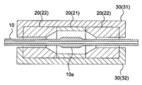
- FIG. 1 It shows the process sectional view of the tubular body arrangement process in embodiment of this invention.
- the process sectional view of the mold arrangement process in embodiment of this invention is shown.
- the process sectional view of the extension start process in embodiment of this invention is shown.
- the process sectional view of the extension end process in embodiment of this invention is shown.
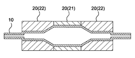
- the process sectional view of the removal process in another embodiment of this invention is shown.
- the process sectional view of the extension end process in another embodiment of this invention is shown.
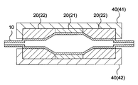
- the process sectional view of the process of arranging the mold in the cooling jacket in embodiment of this invention is shown.
- FIG. 1 to 3 and 7 are process cross-sectional views of each step of the first manufacturing method and the second manufacturing method of the balloon catheter according to the embodiment of the present invention
- FIG. 4 is the first manufacturing of the balloon catheter
- 5 and 6 are process cross-sectional views of the process of the second manufacturing method of the balloon catheter
- FIG. 7 is a process cross-sectional view of the process of the second manufacturing method of the balloon catheter
- FIG. 7 is a process cross-sectional view of the first and second manufacturing methods of the balloon catheter. It is a process sectional view of the process of arranging a mold in a cooling jacket.
- the balloon included in the balloon catheter according to the present invention can be manufactured by applying pressure to the inside of the resin tubular body 10, heating the resin tubular body 10, and stretching the resin tubular body 10 in the longitudinal direction.
- the balloon can be manufactured by blow molding the resin tubular body 10.
- the inside of the resin tubular body 10 may be pressurized before stretching, the inside may be pressurized at the same time as stretching, or the inside may be pressurized during or after stretching.
- the first manufacturing method of the balloon catheter of the present invention includes a tubular body arranging step of arranging the resin tubular body 10 inside the mold 20 and heating the mold 20.
- the resin tubular body 10 is arranged inside the mold 20.
- the resin tubular body 10 is a tubular body made of synthetic resin, and is a so-called parison used for blow molding.
- the mold 20 has a space having the same shape as the outer shape of the balloon inside, and the resin tubular body 10 is arranged in this internal space.
- the material constituting the resin tubular body 10 is preferably a thermoplastic resin.
- the material constituting the resin tubular body 10 include polyolefin resins such as polyethylene, polypropylene and ethylene-propylene copolymer, polyester resins such as polyethylene terephthalate and polyester elastomer, and polyurethane resins such as polyurethane and polyurethane elastomer.
- polyolefin resins such as polyethylene, polypropylene and ethylene-propylene copolymer
- polyester resins such as polyethylene terephthalate and polyester elastomer
- polyurethane resins such as polyurethane and polyurethane elastomer.
- examples thereof include resins, polyphenylene sulfide-based resins, polyamide-based resins such as polyamide and polyamide elastomer, vinyl chloride-based resins, fluorine-based resins, silicone-based resins, and natural rubbers such as latex rubber.
- a polyamide-based resin, a polyester-based resin, and a polyurethane-based resin are preferably used as the material constituting the resin tubular body 10.
- an elastomer resin from the viewpoint of thinning the balloon and flexibility.
- nylon 12 and nylon 11 are examples of materials suitable for the resin tubular body 10, and nylon 12 is relatively easy to mold when blow molding. It is preferably used.
- a polyamide elastomer such as a polyether ester amide elastomer or a polyamide ether elastomer is preferably used from the viewpoint of thinning the balloon and flexibility.
- a polyether ester amide elastomer is preferably used because of its high yield strength and good dimensional stability of the balloon.
- the length of the resin tubular body 10 in the longitudinal direction is preferably longer than the length of the internal space of the mold 20. That is, as shown in FIG. 1, it is preferable that both ends of the resin tubular body 10 are exposed from the mold 20 in a state where the resin tubular body 10 is arranged inside the mold 20. Since the resin tubular body 10 is configured in this way, the stretching start step performed after the tubular body arranging step can be easily performed, and the manufacturing efficiency of the balloon catheter can be improved.
- the length of the resin tubular body 10 in the longitudinal direction is preferably 1.05 times or more, more preferably 1.10 times or more, and 1.15 times the length of the internal space of the mold 20. It is more preferably more than double.
- both ends of the resin tubular body 10 are set in the stretching start step.
- the resin tubular body 10 can be stretched to both sides in the longitudinal direction by sufficiently grasping the resin tubular body 10, and the stretching start step can be easily performed.
- the upper limit of the ratio of the length of the resin tubular body 10 in the longitudinal direction to the length of the internal space of the mold 20 is, for example, 100 times or less and 90 times or less the length of the internal space of the mold 20. It can be 80 times or less and 70 times or less.
- the wall thickness of the resin tubular body 10 can be set according to the wall thickness of the balloon. For example, 3 mm or less, 2 mm or less, 1 mm or less, 0.05 mm or more, 0.07 mm or more, 0.1 mm or more. Can be.
- the resin tubular body 10 preferably has a thick portion 10a having a wall thickness larger than that of other portions.
- a thick portion 10a having a wall thickness larger than that of other portions.
- the resin tubular body 10 can be manufactured by, for example, extrusion molding, injection molding, or the like. Above all, the resin tubular body 10 is preferably manufactured by extrusion molding. That is, it is preferable to have a step of manufacturing the resin tubular body 10 by extrusion molding before the tubular body arranging step. Since the resin tubular body 10 is manufactured by extrusion molding, it is possible to mass-produce the resin tubular body 10 in a short time. Therefore, the efficiency of the production of the balloon catheter can be increased.
- the mold 20 preferably has a plurality of partial molds. Specifically, for example, a central mold 21 for forming a straight pipe portion in the central portion of the balloon and an end mold 22 for forming tapered portions located at both ends of the straight pipe portion of the balloon are used as a central mold. It is preferable that the structure is provided on both sides of the 21. Since the mold 20 has a plurality of partial molds, it is possible to manufacture balloons having various shapes according to the purpose by replacing the central mold 21 and the end mold 22. it can.
- the material constituting the mold 20 is preferably a metal, more preferably iron, copper, aluminum, or an alloy thereof.
- examples of the iron alloy include stainless steel
- examples of the copper alloy include brass
- examples of the aluminum alloy include duralumin. Since the material constituting the mold 20 is iron, copper, aluminum, or an alloy thereof, the heat capacity of the mold 20 is large and the heat transfer property is high, so that the temperature of the entire mold 20 can be easily kept constant. Temperature unevenness is less likely to occur in the resin tubular body 10 arranged inside the mold 20, which facilitates the manufacture of balloons.
- the mold 20 is arranged in the heating jacket 30.
- the heating jacket 30 is used to apply heat to the mold 20.
- the mold arranging step may be performed before the tubular body arranging step, but it is preferably performed after the tubular body arranging step.
- the resin tubular body 10 can be easily arranged inside the mold 20, and the balloon production efficiency can be improved.
- heating start step heating of the heating jacket 30 is started.
- the heating jacket 30 is heated to a set temperature, heat is applied from the heating jacket 30 to the mold 20, and the resin tubular body 10 arranged inside the mold 20 is heated.
- the temperature of the heating jacket 30 is preferably higher than the heating target temperature of the mold 20. By making the temperature of the heating jacket 30 higher than the heating target temperature of the mold 20, it becomes easy to efficiently raise the temperature of the mold 20 to the heating target temperature.
- the lower limit of the temperature of the heating jacket 30 is preferably the same temperature as the heating target temperature of the mold 20, more preferably 5 ° C higher than the heating target temperature of the mold 20, and 10 ° C higher. Is even more preferable, the temperature is even more preferably 15 ° C. higher, and the temperature is particularly preferably 20 ° C. higher.
- the upper limit of the temperature of the heating jacket 30 is preferably 250 ° C. higher than the heating target temperature of the mold 20, more preferably 225 ° C. higher, and 200 ° C. higher. More preferred. By setting the upper limit of the temperature of the heating jacket 30 in the above range, it becomes easy to adjust the temperature of the mold 20.
- the heating start step may be performed after the mold placement step, but it is preferably performed before the mold placement step. By performing the heating start step before the mold placement step, the temperature of the heating jacket 30 has reached the set value when the mold placement step is performed, and the mold 20 is quickly heated. Can be done.
- the heat dissipation rate of the mold 20 is preferably 30% or less, more preferably 10% or less, and further preferably 1% or less.
- the heat dissipation rate of the mold 20 can be obtained by the formula (heat dissipation amount (J) / heat storage amount (J)) ⁇ 100.
- the amount of heat storage is the amount of heat possessed by the mold 20 in a state of being heated to a certain temperature, and is determined by the material and mass of the mold 20.
- the amount of heat radiated is the amount of heat lost from the mold 20 within 30 seconds after the energization of the heating jacket 30 is completed or the heating jacket 30 is removed from the mold 20, and the material, mass, and shape of the mold 20 ( Surface area), temperature, and ambient temperature.
- the temperature of the mold 20 decreases from the surface, if the upper limit of the heat dissipation rate of the mold 20 is set within the above range, the temperature of the central portion of the mold 20, which is largely related to the manufacture of the balloon, decreases. It is difficult and the heat retention of the mold 20 is high. Therefore, temperature unevenness is less likely to occur in the resin tubular body 10 arranged inside the mold 20, and it becomes easier to manufacture a balloon having a uniform wall thickness and less likely to bend.
- the stretching start step stretching of the resin tubular body 10 in the longitudinal direction is started. It is preferable that the resin tubular body 10 is stretched in both directions in the longitudinal direction of the resin tubular body 10. Examples of the method of extending the resin tubular body 10 to both sides in the longitudinal direction include grasping both ends of the resin tubular body 10 and pulling both ends to extend the resin tubular body 10 to both sides in the longitudinal direction. Be done.
- the calorific value (J) of the heating jacket 30 may be 1.1 times or more the calorific value (J) of the mold 20. It is preferably 3 times or more, more preferably 5 times or more, and even more preferably 5 times or more.
- the lower limit of the ratio of the amount of heat between the heating jacket 30 and the mold 20 is set to the above range, the amount of heat of the heating jacket 30 can be made sufficiently larger than the amount of heat of the mold 20, and the heating jacket 30 When the mold 20 is arranged inside, the temperature drop of the heating jacket 30 can be reduced. As a result, the time required for raising the temperature of the mold 20 can be shortened.
- the upper limit of the ratio of the amount of heat between the heating jacket 30 and the mold 20 can be, for example, 300 times or less, 200 times or less, and 100 times or less.
- the resin tubular body 10 is stretched to a desired length, and then, as shown in FIG. 4, the stretching of the resin tubular body 10 is completed in the stretching end step.
- a step of applying pressure to the inside of the resin tubular body 10 may be performed.
- a method of applying pressure to the inside of the resin tubular body 10 for example, one end of the resin tubular body 10 is sealed, and air or nitrogen is introduced from the other end to the inside of the resin tubular body 10. Examples include sending a fluid such as water from both ends of the resin tubular body 10 to the inside of the resin tubular body 10.
- the step of applying pressure to the inside of the resin tubular body 10 is preferably performed before the stretching start step.
- the heating end step the heating of the heating jacket 30 is completed. Specifically, for example, the energization of the heating jacket 30 is stopped, and the heating of the heating jacket 30 is terminated.
- the heating end step is performed before the extension end step.
- heat is not supplied from the heating jacket 30 to the mold 20 during the stretching of the resin tubular body 10, and the heater block heating the heating jacket 30
- the mold 20 is not easily affected by the temperature, and the heat conduction of the mold 20 itself makes the temperature of the entire mold 20 uniform, so that temperature unevenness is less likely to occur.
- the balloon manufactured by the mold 20 has a uniform wall thickness and is less likely to be bent.
- the heating end step is performed before the extension end step, but it is preferable to perform the heating end step before the extension start step. That is, it is preferable to perform the stretching start step and the stretching end step after the heating end step is completed.
- the temperature of the entire mold 20 before the stretching start step can be made uniform, and temperature unevenness is less likely to occur. It is possible to improve the quality of the balloon.
- a heating restart step for restarting the heating of the heating jacket 30.
- the heating jacket 30 is preferably heated to a temperature higher than the heating target temperature of the heating jacket 30 in the heating start step.
- the heating jacket 30 is heated to heat the mold 20 to the target temperature, the mold 20 is kept at the target temperature for a certain period of time in order to perform the balloon annealing treatment, and then the heating of the heating jacket 30 is completed. It is preferable to have a reheating end step.
- the balloon can be sufficiently annealed by heating the mold 20 to a target temperature, keeping the mold 20 at the target temperature for a certain period of time, and then performing the reheating end step.
- a reheating end step of ending the heating of the heating jacket 30 is performed, and then the mold 20 is kept constant at the target temperature. It is also preferable to carry out the annealing treatment of the balloon at a time. By heating the mold 20 to the target temperature and then performing a reheating end step to keep the mold 20 at the target temperature for a certain period of time, heat is not supplied from the heating jacket 30 to the mold 20. Therefore, the heat conduction of the mold 20 itself makes the temperature of the entire mold 20 uniform, and temperature unevenness is less likely to occur.
- the heating restart step is preferably performed after the heating end step, but more preferably after the extension end step.
- a step of applying pressure to the inside of the resin tubular body 10 may be performed.
- the steps of applying pressure to the inside of the resin tubular body 10 are performed before, after, or at the same time as the stretching start step, and at the same time or after the stretching end step, they are added to the inside of the resin tubular body 10 in these steps. It is preferable to apply a pressure lower than the pressure in the heating restart step.
- the second manufacturing method of the balloon catheter of the present invention includes a tubular body arranging step of arranging the resin tubular body 10 inside the mold 20 and heating the mold 20.
- the description of the portion overlapping with the above-mentioned description of the first manufacturing method will be omitted.
- the mold 20 is removed from the heating jacket 30.
- the removing step is performed before the stretching end step.
- the actual temperature of the mold 20 is raised by stopping the heat supply to the mold 20 by the heating jacket 30 when the resin tubular body 10 is stretched.
- the influence of so-called temperature overshoot, which is a phenomenon in which the target temperature is exceeded, is eliminated, and the entire temperature of the mold 20 becomes uniform due to the heat conduction of the mold 20 itself.
- the balloon produced by the mold 20 does not have a thickness variation or bending, and can be a high-quality balloon.
- the removing step is performed before the stretching end step, but it is preferable to perform the removing step before the stretching start step. That is, it is preferable to perform the stretching start step and the stretching end step after performing the removing step.
- the temperature of the mold 20 before the stretching start step is made uniform as a whole, temperature unevenness is less likely to occur in the mold 20, and the balloon is made of meat. It is less likely that the thickness will vary or bend.
- the removing step it is preferable to have a mold rearranging step of arranging the mold 20 in the heating jacket 30 and a heating restarting step of restarting the heating of the heating jacket 30.
- the mold 20 is reheated by heating the heating jacket 30, and the formed balloon is heated, so that the annealing treatment for removing the residual stress of the balloon can be performed. Therefore, the dimensional stability and the physical stability of the balloon can be improved.
- the same heating jacket 30 used in the mold rearranging step may be used, or a different one may be used. Above all, it is preferable to use the same heating jacket 30 used in the mold rearranging step as the heating jacket 30 used in the mold rearranging step.
- the same heating jacket 30 used in the mold rearranging step in the mold rearranging step By using the same heating jacket 30 used in the mold rearranging step in the mold rearranging step, the number of heating jackets 30 used for manufacturing the balloon becomes one, and the balloon manufacturing cost can be reduced.
- the temperature difference between the heating jacket 30 at the end of the removing step and the heating jacket 30 at the start of the mold rearrangement step is preferably 100 ° C. or less.
- the temperature difference between the heating jacket 30 at the end of the removing step and the heating jacket 30 at the start of the mold rearrangement step is preferably 10 ° C. or less.
- the temperature difference between the heating jacket 30 at the end of the removing step and the heating jacket 30 at the start of the mold rearrangement step is preferably 10 ° C. or lower, more preferably 5 ° C. or lower. It is more preferably 3 ° C. or lower.
- the temperature difference between the heating jacket 30 at the end of the removing process and the heating jacket 30 at the start of the mold rearrangement process is small, and the temperature of the heating jacket 30 at the end of the removing process and the gold
- the temperature of the heating jacket 30 at the start of the mold rearrangement step may be the same.
- the mold rearrangement step may be performed before the heating resumption step, but it is preferably performed after the heating resumption step. By performing the mold rearrangement step after the heating restart step, the mold rearrangement step can be performed immediately after the temperature of the heating jacket 30 reaches the set value, and the mold 20 can be quickly reheated. It becomes possible to do.
- the heating jacket 30 preferably has a plurality of partially heating jackets. Since the heating jacket 30 has a plurality of partial heating jackets, the heating jacket 30 can be closed by connecting the partial heating jackets, and the heating jackets 30 can be closed by disconnecting the partial heating jackets. Since the 30 can be opened, the heating jacket 30 can be easily opened and closed, the mold arranging step and the removing step can be easily performed, and the balloon production efficiency can be improved.
- a plurality of partial heating jackets may be arranged in the circumferential direction of the mold 20, or a plurality of partial heating jackets may be arranged in the axial direction of the mold 20.
- the heat jacket 30 can have a semi-cracked structure, and the mold 20 can be easily arranged inside the heating jacket 30.
- the temperature of each partial heating jacket can be set, and the heating temperature of the mold 20 is different in the axial direction of the mold 20. It becomes possible to do.
- the heating jacket 30 includes a first partial heating jacket 31 on one side surface side of the mold 20 and a second partial heating jacket 32 on the other side surface side of the mold 20, and the removing step is a first step. It is preferable that at least one of the partial heating jacket 31 and the second partial heating jacket 32 is separated from the mold 20. By performing the removing step so that at least one of the first partial heating jacket 31 and the second partial heating jacket 32 is separated from the mold 20, the mold 20 can be easily removed from the heating jacket 30 and a balloon is produced. It is possible to improve the efficiency of.
- first partial heating jacket 31 and the second partial heating jacket 32 are connected to each other via a hinge portion. Since the first partial heating jacket 31 and the second partial heating jacket 32 are connected to each other via the hinge portion, the opening and closing of the first partial heating jacket 31 and the second partial heating jacket 32 becomes easy and reliable. ..
- the first partial heating jacket 31 and the second partial heating jacket 32 may be connected via a cylinder. Since the first partial heating jacket 31 and the second partial heating jacket 32 are connected to each other via a cylinder, the thermal jacket 30 can be opened and closed by the cylinder, and the opening and closing operation of the thermal jacket 30 is easy and reliable. Further, it is possible to control the force of pressing the first partial heating jacket 31 and the second partial heating jacket 32 against the inclusions such as the mold 20.
- Examples of the type of cylinder include an air cylinder, a hydraulic cylinder, an electric cylinder, and the like.
- the heating jacket 30 includes a first partial heating jacket on one end side of the mold 20 and a second partial heating jacket on the other end side of the mold 20 and is removed. It is also preferable that at least one of the first partial heating jacket and the second partial heating jacket is separated from the mold 20.
- the heating jacket 30 includes a first partial heating jacket on one end side of the mold 20 and a second partial heating jacket on the other end side, and the removal step is performed by at least the first partial heating jacket and the second partial heating jacket.
- a step of arranging the mold 20 in the cooling jacket 40 after the stretching end step it becomes possible to quickly cool the mold 20 in the heated state after the stretching end step. , The efficiency of balloon manufacturing can be increased.
- the cooling jacket 40 is used to cool the mold 20.
- the mold 20 is cooled by using the cooling jacket 40 when the mold is rapidly cooled from the balloon molding temperature or the annealing temperature to room temperature, for example, to a temperature slightly higher than the sterilization temperature of about 45 ° C to 55 ° C.
- the mold 20 is rapidly cooled to remove residual stress, and the mold 20 is taken out from the cooling jacket 40.
- the cooling of the cooling jacket 40 is completed and the mold 20 is held at a temperature slightly higher than the above-mentioned sterilization temperature for a certain period of time.
- the residual stress may be removed, and then the mold 20 may be placed in the cooling jacket 40 again, or the cooling jacket 40 may be started to be cooled to cool the mold 20 to room temperature.
- the cooling jacket 40 can be cooled to a set temperature in the cooling start step, and the cooling jacket 40 is arranged inside the mold 20 by cooling the mold 20. It is possible to sufficiently cool the resin tubular body 10 and the balloon.
- It may have a cooling end step for terminating the cooling of the cooling jacket 40. Further, the cooling jacket removing step of removing the mold 20 from the cooling jacket 40 may be provided. By performing the cooling end process and the cooling jacket removal process, it is possible to move to the next balloon production process after the balloon is cooled and the production is completed, and the balloon production efficiency can be improved and continuous production can be performed. it can.
- the cooling jacket 40 includes a first partial cooling jacket 41 on one side surface side of the mold 20 and a second partial cooling jacket 42 on the other side surface side of the mold 20. , It is preferable to have a configuration having a plurality of partial cooling jackets. Further, it is preferable that the first partial cooling jacket 41 and the second partial cooling jacket 42 are connected to each other via a hinge portion. Since the cooling jacket 40 has a configuration in which the first partial cooling jacket 41 and the second partial cooling jacket 42 are connected to each other via a hinge portion, a step of arranging the mold 20 in the cooling jacket 40 and a process of arranging the mold 20 The process of removing the mold 20 from the cooling jacket 40 becomes easier.
- the first manufacturing method of the balloon catheter of the present invention is a manufacturing method of a balloon catheter having a shaft extending in the perspective direction and a balloon provided on the distal side of the shaft. Therefore, there are a tubular body placement step of arranging the resin tubular body inside the mold, a mold placement step of arranging the mold inside the heating jacket, and a heating start step of starting heating of the heating jacket. It has a stretching start step for starting stretching of the resin tubular body in both directions in the longitudinal direction, a stretching ending step for ending the stretching of the resin tubular body, and a heating ending step for ending the heating of the heating jacket. It is characterized in that the heating end step is performed before the extension end step.
- the second manufacturing method of the balloon catheter of the present invention is a manufacturing method of a balloon catheter having a shaft extending in the perspective direction and a balloon provided on the distal side of the shaft.
- a tubular body placement process in which the resin tubular body is placed inside the mold, a mold placement step in which the mold is placed in the heating jacket, a heating start step in which heating of the heating jacket is started, and a resin cylinder It has a stretching start step for starting stretching in both sides in the longitudinal direction of the shape, a stretching ending step for ending the stretching of the resin tubular body, and a stretching step for removing the mold from the heating jacket. It is characterized in that the removal process is performed before the final process.
- the heating of the heating jacket is terminated before the extension of the resin tubular body arranged inside the mold to both sides in the longitudinal direction is completed.
- the heat supply from the heating jacket to the mold can be stopped by removing the mold from the heating jacket, and the heat conduction of the mold itself tends to make the temperature of the entire mold uniform. That is, since the resin tubular body is stretched while the temperature of the entire mold is uniform, temperature unevenness is unlikely to occur in the resin tubular body arranged inside the mold, and the wall thickness is uniform. It is possible to form a balloon that is less likely to bend.
Landscapes
- Health & Medical Sciences (AREA)
- Heart & Thoracic Surgery (AREA)
- Engineering & Computer Science (AREA)
- Life Sciences & Earth Sciences (AREA)
- Anesthesiology (AREA)
- Child & Adolescent Psychology (AREA)
- Biophysics (AREA)
- Pulmonology (AREA)
- Manufacturing & Machinery (AREA)
- Biomedical Technology (AREA)
- Hematology (AREA)
- Animal Behavior & Ethology (AREA)
- General Health & Medical Sciences (AREA)
- Public Health (AREA)
- Veterinary Medicine (AREA)
- Media Introduction/Drainage Providing Device (AREA)
- Materials For Medical Uses (AREA)
Abstract
金型全体を均一に加熱することができ、高品位であるバルーンを有するバルーンカテーテルを製造することができる方法を提供する。遠近方向に延在しているシャフトと、シャフトの遠位側に設けられているバルーンと、を有するバルーンカテーテルの製造方法であって、樹脂製筒状体(10)を金型(20)の内部に配置する筒状体配置工程と、金型(20)を加熱ジャケット(30)内に配置する金型配置工程と、加熱ジャケット(30)の加熱を開始する加熱開始工程と、樹脂製筒状体(10)の長手方向への伸張を開始する伸張開始工程と、樹脂製筒状体(10)の伸張を終了する伸張終了工程と、加熱ジャケット(30)の加熱を終了する加熱終了工程と、を有しており、伸張終了工程の前に加熱終了工程を行う。
Description
本発明は、バルーンを有するバルーンカテーテルの製造方法に関するものである。
体内で血液が循環するための流路である血管に狭窄が生じ、血液の循環が滞ることにより、様々な疾患が発生することが知られている。特に心臓に血液を供給する冠状動脈に狭窄が生じると、狭心症、心筋梗塞等の重篤な疾病をもたらすおそれがある。このような血管の狭窄部を治療する方法の一つとして、バルーンカテーテルを用いて狭窄部を拡張させる手技(PTA、PTCAといった血管形成術等)がある。血管形成術は、バイパス手術のような開胸術を必要としない低侵襲療法であり、広く行われている。
例えば、特許文献1には、チューブ状パリソンの両側を所定割合で延伸し、中央部に所定幅の未延伸部を残した状態の準備パリソンを形成して金型内に装着し、二次転移温度以上で一次転移温度以下の第一成形温度に加熱し、準備パリソン内に加圧流体を流入させると共に一次延伸して、金型内面形状に合致するバルーン部とテーパー部と小径接続部を有するバルーン形状に一次成形し、その後で、金型を第一成形温度以上で一次転移温度以下の第二成形温度に加熱する工程と、パリソンの両側を再延伸する工程により、テーパー部および接続部を肉薄とする二次成形を行うことを特徴とするカテーテル用バルーンの製造方法が記載されており、金型は加熱手段によってその周囲から一体的に加熱される構成であり、加熱手段を3分割してバルーン部加熱手段と端部加熱手段とから構成すると、パリソンのバルーン部とテーパー部と接続部とをそれぞれ独立して温度制御可能となることが記載されている。
特許文献2には、パリソンを形成するパリソン形成工程と、パリソンを金型によりブロー成形するブロー成形工程を有する医療用バルーンの製造方法であって、ブロー成形工程において、パリソン形成工程によって形成されたパリソンを、分離型であって、加温手段であるヒーターと冷却手段である冷却管とが外側に配されている金型に挿入し、両端を封止して内圧をかけた状態で加熱・加圧し、パリソンが延びている方向に延伸して、金型内で加熱されている部分のパリソンを分離型の内壁面に密着させるように内圧で膨張させてバルーン形状に成形し、成形温度以上かつポリマーの融点以下の温度で内圧をかけながら一定時間保持してアニール処理を行うことで形状を記憶させた後にパリソンを常温に冷却することが記載されている。
特許文献3には、複屈折性の高分子材料から構成される管状パリソンをブロー成形して、バルーンの拡張自在の筒状部を成形する成形工程を有している医療用カテーテルに配置されるバルーンの製造方法であって、成形工程は管状パリソンの内部に圧力を付加した状態で常温にて軸方向に延伸させる第1延伸工程と、第1延伸工程の後において、加熱された管状パリソンを軸方向に延伸させながら、管状パリソンの内部に付加された圧力によって管状パリソンを膨出させる第2延伸工程とを有することが記載されている。
特許文献4には、バルーンを形成する方法であって、押出成形されたパリソンの半径方向の膨張に先立ち、バルーンのコーンおよびウエスト部位の厚みを減ずるために、種々の方法で膨張または再形成以前に縦方向に予備延伸されてよいこと、ブロー工程はその後に、加熱された流体中への急速浸漬が行われ、伸張下での加圧を利用してよく、異なる加圧で連続浸漬、および材料が加熱された後に圧縮性または非圧縮性流体で振動加圧してよいこと、加熱はパリソン中に注入された加圧流体を加熱することにより達成されてもよいことが記載されており、また、ブロー成形温度および圧力に関連して、ブロー成形の後にバルーンは単に冷却されても、さらに高い圧力および/または温度でヒートセットされても、または中間の圧力および/または温度でヒートシュリンクされてもよいことが記載されている。
特許文献5には、直鎖状低密度ポリエチレン樹脂で元チューブを成形し、該元チューブを架橋して架橋チューブを製造し、該架橋チューブをブロー成形により延伸してバルーンを製造し、該バルーンをカテーテルに装着して拡張用カテーテルを製造する拡張用カテーテルの製造方法が記載されており、所望の外径寸法のキャビティをもつバルーン成形金型(ブロー金型)に架橋チューブを挿入しブロー成形機にセットし、適切な温度に昇温した後に縦方向へ延伸してブロー加圧によってバルーン状に賦型すること、縦延伸工程とブロー工程を連続して同じ金型内で実施することができること、両工程の温度を同じレベルに設定することができること、また、架橋チューブをブロー成形する前工程として架橋チューブの縦延伸を実施するが、架橋チューブを延伸した直後にブロー成形を行っても、暫く時間をおいた後に実施してもよいことが記載されている。
特許文献1~5のようなバルーンカテーテルの製造方法では、通常、バルーンを成形する金型の外方にヒーターブロック(カートリッジヒーター)を有するジャケットが配置されている。バルーンの一般的な製造方法としては、まず、ジャケットのヒーターブロックに通電し、ジャケットを昇温して金型を加熱する。次に、ジャケットの温度が目標温度に達したらヒーターブロックの通電を切り、ジャケットの昇温を停止して金型の加熱を止めることによって金型の温度の制御を行う。そして、金型の内部に配置した樹脂製筒状体を加工し、バルーンを製造する。しかし、このようなヒーターブロックへの通電のオン/オフによる温度の制御方法では、金型の温度にムラが大きく発生してしまい、金型全体を均一に加熱することが困難である。その結果、金型の内部に配置している樹脂製筒状体にも温度ムラが発生し、成形したバルーンの肉厚が不均一であったり、バルーンが曲がったりするという問題があった。
また、ヒーターブロックを有するジャケットおよび金型が両方とも金属等の剛体で構成されているため、ジャケットと金型とが直接接触している部分、および、ジャケットと金型との間に距離があいており、ジャケットと金型との間に空気層が存在している部分の両方が存在している。ジャケットと金型との接触の度合いや、ジャケットと金型との距離も各場所によって異なっているため、ジャケットから金型への熱の伝わり方が均一ではなく、金型全体を均一に加熱することが困難であるという問題もあった。
さらに、ジャケットは複数のヒーターブロックを有しているが、各ヒーターブロックの加熱性能にはそれぞれ個体差があり、また、各ヒーターブロックの劣化の度合いも異なるため、加熱性能の高いヒーターブロックに面している金型の部分は温度が上がりやすく、加熱性能の低いヒーターブロックに面している金型の部分は温度が上がりにくい。その結果、金型全体の温度にムラが発生しやすく、肉厚が均一であって曲がりのないバルーンを成形することが難しいという問題もあった。
本発明は、前記の事情に鑑みてなされたものであり、その目的は、金型全体を均一に加熱することができ、高品位であるバルーンを有するバルーンカテーテルを製造する方法を提供することにある。
前記課題を解決することができたバルーンカテーテルの第1の製造方法は、遠近方向に延在しているシャフトと、シャフトの遠位側に設けられているバルーンと、を有するバルーンカテーテルの製造方法であって、樹脂製筒状体を金型の内部に配置する筒状体配置工程と、金型を加熱ジャケット内に配置する金型配置工程と、加熱ジャケットの加熱を開始する加熱開始工程と、樹脂製筒状体の長手方向両側への伸張を開始する伸張開始工程と、樹脂製筒状体の伸張を終了する伸張終了工程と、加熱ジャケットの加熱を終了する加熱終了工程と、を有しており、伸張終了工程の前に加熱終了工程を行うことを特徴とするものである。
本発明のバルーンカテーテルの製造方法において、伸張開始工程の前に加熱終了工程を行うことが好ましい。
本発明のバルーンカテーテルの製造方法において、加熱終了工程の後に、加熱ジャケットの加熱を再開する加熱再開工程を有することが好ましい。
前記課題を解決することができたバルーンカテーテルの第2の製造方法は、遠近方向に延在しているシャフトと、シャフトの遠位側に設けられているバルーンと、を有するバルーンカテーテルの製造方法であって、樹脂製筒状体を金型の内部に配置する筒状体配置工程と、金型を加熱ジャケット内に配置する金型配置工程と、加熱ジャケットの加熱を開始する加熱開始工程と、樹脂製筒状体の長手方向両側への伸張を開始する伸張開始工程と、樹脂製筒状体の伸張を終了する伸張終了工程と、加熱ジャケットから金型を外す外し工程と、を有しており、伸張終了工程の前に外し工程を行うことを特徴とするものである。
本発明のバルーンカテーテルの製造方法において、伸張開始工程の前に外し工程を行うことが好ましい。
本発明のバルーンカテーテルの製造方法において、外し工程の後に、金型を加熱ジャケット内に配置する金型再配置工程と該加熱ジャケットの加熱を再開する加熱再開工程とを有することが好ましい。
本発明のバルーンカテーテルの製造方法において、外し工程の終了時の加熱ジャケットと、金型再配置工程の開始時の加熱ジャケットとの温度の差は、100℃以下であることが好ましい。
本発明のバルーンカテーテルの製造方法において、外し工程の終了時の加熱ジャケットと、金型再配置工程の開始時の加熱ジャケットとの温度の差は、10℃以下であることがより好ましい。
本発明のバルーンカテーテルの製造方法において、加熱ジャケットは、複数の部分加熱ジャケットを有していることが好ましい。
本発明のバルーンカテーテルの製造方法において、加熱ジャケットは、金型の一方側面側にある第1部分加熱ジャケットと、金型の他方側面側にある第2部分加熱ジャケットと、を含んでおり、外し工程は、第1部分加熱ジャケットと第2部分加熱ジャケットの少なくとも一方を金型から離間させるものであることが好ましい。
本発明のバルーンカテーテルの製造方法において、第1部分加熱ジャケットと第2部分加熱ジャケットは、ヒンジ部を介して互いに接続されていることが好ましい。
本発明のバルーンカテーテルの製造方法において、加熱ジャケットは、金型の一方端側にある第1部分加熱ジャケットと、金型の他方端側にある第2部分加熱ジャケットと、を含んでおり、外し工程は、第1部分加熱ジャケットと第2部分加熱ジャケットの少なくとも一方を金型から離間させるものであることも好ましい。
本発明のバルーンカテーテルの製造方法において、金型配置工程の前に加熱開始工程を行うことが好ましい。
本発明のバルーンカテーテルの製造方法において、樹脂製筒状体の伸張を終了する伸張終了工程の後に、金型を冷却ジャケット内に配置する工程を更に有していることが好ましい。
本発明のバルーンカテーテルの製造方法によれば、金型の内部に配置した樹脂製筒状体の長手方向両側への伸張が終了する前に、加熱ジャケットの加熱を終了する、または加熱ジャケットから金型を外すことにより、加熱ジャケットから金型への熱供給を止めることができ、金型自体の熱伝導によって金型全体の温度が均一なものとなりやすい。つまり、金型全体の温度が均一な状態で樹脂製筒状体の伸張を行うため、金型の内部に配置されている樹脂製筒状体に温度ムラが発生しにくく、肉厚が均一であり、曲がりが生じにくいバルーンを有するバルーンカテーテルを成形することができる。
以下、下記実施の形態に基づき本発明をより具体的に説明するが、本発明はもとより下記実施の形態によって制限を受けるものではなく、前・後記の趣旨に適合し得る範囲で適当に変更を加えて実施することも勿論可能であり、それらはいずれも本発明の技術的範囲に包含される。なお、各図面において、便宜上、ハッチングや部材符号等を省略する場合もあるが、かかる場合、明細書や他の図面を参照するものとする。また、図面における種々部材の寸法は、本発明の特徴の理解に資することを優先しているため、実際の寸法とは異なる場合がある。
図1~図3および図7は本発明の実施の形態におけるバルーンカテーテルの第1の製造方法および第2の製造方法の各工程の工程断面図であり、図4はバルーンカテーテルの第1の製造方法の伸張終了工程の工程断面図であり、図5および図6はバルーンカテーテルの第2の製造方法の工程の工程断面図であり、図7はバルーンカテーテルの第1および第2の製造方法の金型を冷却ジャケット内に配置する工程の工程断面図である。
本発明におけるバルーンカテーテルが有するバルーンは、樹脂製筒状体10の内部に圧力を加え、樹脂製筒状体10を加熱し、長手方向へ延伸することによって製造することができる。具体的には、樹脂製筒状体10にブロー成形をすることによってバルーンを製造することができる。バルーンの製造において、樹脂製筒状体10の延伸前から内部を加圧してもよく、延伸と同時に内部を加圧してもよく、また、延伸中や延伸後に内部を加圧してもよい。中でも、樹脂製筒状体10の内部に圧力を加えた状態で樹脂製筒状体10を長手方向へ延伸することが好ましい。バルーンを、樹脂製筒状体10の内部に圧力を加えた状態で長手方向へ延伸して製造することにより、バルーンカテーテルの製造効率を高めることができる。
図1~図4に示すように、本発明のバルーンカテーテルの第1の製造方法は、樹脂製筒状体10を金型20の内部に配置する筒状体配置工程と、金型20を加熱ジャケット30内に配置する金型配置工程と、加熱ジャケット30の加熱を開始する加熱開始工程と、樹脂製筒状体10の長手方向両側への伸張を開始する伸張開始工程と、樹脂製筒状体10の伸張を終了する伸張終了工程と、加熱ジャケット30の加熱を終了する加熱終了工程と、を有しており、伸張終了工程の前に加熱終了工程を行うことを特徴とするものである。
図1に示すように、筒状体配置工程は、樹脂製筒状体10を金型20の内部に配置する。樹脂製筒状体10は、合成樹脂から構成されている筒状物であり、所謂、ブロー成形に用いるパリソンである。金型20は、内部にバルーンの外形と同じ形状の空間を有しており、この内部空間に樹脂製筒状体10を配置する。
樹脂製筒状体10を構成する材料は、熱可塑性樹脂であることが好ましい。樹脂製筒状体10を構成する材料としては、例えば、ポリエチレン、ポリプロピレン、エチレン-プロピレン共重合体等のポリオレフィン系樹脂、ポリエチレンテレフタレート、ポリエステルエラストマー等のポリエステル系樹脂、ポリウレタン、ポリウレタンエラストマー等のポリウレタン系樹脂、ポリフェニレンサルファイド系樹脂、ポリアミド、ポリアミドエラストマー等のポリアミド系樹脂、塩化ビニル系樹脂、フッ素系樹脂、シリコーン系樹脂、ラテックスゴム等の天然ゴム等が挙げられる。これらは1種のみを用いてもよく、2種以上を併用してもよい。中でも、樹脂製筒状体10を構成する材料は、ポリアミド系樹脂、ポリエステル系樹脂、ポリウレタン系樹脂が好適に用いられる。特に、バルーンの薄膜化や柔軟性の点からエラストマー樹脂を用いることが好ましい。例えば、ポリアミド系樹脂の中で樹脂製筒状体10に好適な材料としては、ナイロン12、ナイロン11等が挙げられ、ブロー成形する際に比較的容易に成形可能である点から、ナイロン12が好適に用いられる。また、バルーンの薄膜化や柔軟性の点から、ポリエーテルエステルアミドエラストマー、ポリアミドエーテルエラストマー等のポリアミドエラストマーが好ましく用いられる。中でも、降伏強度が高く、バルーンの寸法安定性が良好な点から、ポリエーテルエステルアミドエラストマーが好ましく用いられる。
樹脂製筒状体10の長手方向の長さは、金型20の内部空間の長さよりも長いことが好ましい。つまり、図1に示すように、樹脂製筒状体10を金型20の内部に配置した状態において、樹脂製筒状体10の両端部が金型20から露出していることが好ましい。樹脂製筒状体10がこのように構成されていることにより、筒状体配置工程の後に行う伸張開始工程が行いやすくなり、バルーンカテーテルの製造効率を高めることが可能となる。
樹脂製筒状体10の長手方向の長さは、金型20の内部空間の長さの1.05倍以上であることが好ましく、1.10倍以上であることがより好ましく、1.15倍以上であることがさらに好ましい。樹脂製筒状体10の長手方向の長さと金型20の内部空間の長さとの比の下限値をこのように設定することにより、伸張開始工程において、樹脂製筒状体10の両端部を十分に把持して、樹脂製筒状体10を長手方向両側へ伸張させることができ、伸張開始工程が行いやすくなる。また、樹脂製筒状体10の長手方向の長さと金型20の内部空間の長さとの比の上限値は、例えば、金型20の内部空間の長さの100倍以下、90倍以下、80倍以下、70倍以下とすることができる。
樹脂製筒状体10の肉厚は、バルーンの肉厚に応じて設定することができるが、例えば、3mm以下、2mm以下、1mm以下、0.05mm以上、0.07mm以上、0.1mm以上とすることができる。
樹脂製筒状体10は、他の部分よりも肉厚が大きい厚肉部10aを有していることが好ましい。厚肉部10aをバルーンの直管部やテーパー部といった、外径を大きく拡張する部分に位置することにより、バルーンの肉厚を十分に確保することができ、バルーンの耐久性を高めることができる。
樹脂製筒状体10は、例えば、押出成形、射出成形等によって製造することができる。中でも、樹脂製筒状体10は、押出成形によって製造することが好ましい。つまり、筒状体配置工程の前に、押出成形によって樹脂製筒状体10を製造する工程を有することが好ましい。樹脂製筒状体10が押出成形によって製造されていることにより、樹脂製筒状体10を短時間で大量に製造することが可能となる。そのため、バルーンカテーテルの生産の効率を高めることができる。
金型20は、複数の部分金型を有していることが好ましい。具体的には、例えば、バルーンの中央部の直管部を形成する中央部金型21と、バルーンの直管部の両端に位置するテーパー部を形成する端部金型22を中央部金型21の両側に有する構成であることが好ましい。金型20が複数の部分金型を有している構成であることにより、中央部金型21や端部金型22を取り替えることによって、目的に応じた様々な形状のバルーンを製造することができる。
金型20を構成する材料は、金属であることが好ましく、鉄、銅、アルミニウム、またはこれらの合金であることがより好ましい。例えば、鉄の合金としてはステンレス等が挙げられ、銅の合金としては真鍮等が挙げられ、アルミニウムの合金としてはジュラルミン等が挙げられる。金型20を構成する材料が鉄、銅、アルミニウム、またはこれらの合金であることにより、金型20の熱容量が大きく、また、伝熱性が高いため、金型20全体の温度を一定にしやすく、金型20の内部に配置されている樹脂製筒状体10に温度ムラが発生しにくく、バルーンの製造が行いやすくなる。
図2に示すように、金型配置工程は、金型20を加熱ジャケット30内に配置する。加熱ジャケット30は、金型20に熱を加えるために使用する。
金型配置工程は、筒状体配置工程の前に行ってもよいが、筒状体配置工程の後に行うことが好ましい。バルーンの製造において、金型配置工程を筒状体配置工程の後に行うことにより、樹脂製筒状体10を金型20の内部に配置しやすく、バルーンの生産効率を向上させることができる。
加熱開始工程において、加熱ジャケット30の加熱を開始する。加熱開始工程の後、加熱ジャケット30を設定された温度まで加熱し、加熱ジャケット30から金型20へ熱を加え、金型20の内部に配置されている樹脂製筒状体10を加熱する。
加熱ジャケット30の温度は、金型20の加熱目標温度よりも高いことが好ましい。加熱ジャケット30の温度を金型20の加熱目標温度よりも高くすることにより、金型20の温度を加熱目標温度まで効率的に上昇させやすくなる。
加熱ジャケット30の温度の下限値は、金型20の加熱目標温度と同じ温度であることが好ましく、金型20の加熱目標温度よりも5℃高い温度であることがより好ましく、10℃高い温度であることがさらに好ましく、15℃高い温度であることがさらにより好ましく、20℃高い温度であることが特に好ましい。加熱ジャケット30の温度の下限値を上記の範囲に設定することにより、金型20の温度を加熱目標温度まで短時間で上げることが可能となる。また、加熱ジャケット30の温度の上限値は、金型20の加熱目標温度よりも250℃高い温度であることが好ましく、225℃高い温度であることがより好ましく、200℃高い温度であることがさらに好ましい。加熱ジャケット30の温度の上限値を上記の範囲に設定することにより、金型20の温度を調節しやすくなる。
加熱開始工程は、金型配置工程の後に行ってもよいが、金型配置工程の前に行うことが好ましい。加熱開始工程を金型配置工程の前に行うことにより、金型配置工程を行う際に加熱ジャケット30の温度が設定値に達した状態となっており、金型20の加熱を迅速に行うことができる。
金型20の放熱率は、30%以下であることが好ましく、10%以下であることがより好ましく、1%以下であることがさらに好ましい。金型20の放熱率は、(放熱量(J)/蓄熱量(J))×100の式によって求めることができる。蓄熱量は、ある温度まで加熱された状態の金型20が持つ熱量であり、金型20の材質と質量によって決まる。放熱量は、加熱ジャケット30の通電が終了、もしくは加熱ジャケット30が金型20から取り外されてから30秒後までに金型20から失われる熱量であり、金型20の材質、質量や形状(表面積)、温度、周囲の温度によって決まる。金型20は表面から温度が低下していくため、金型20の放熱率の上限値を上記の範囲に設定すれば、バルーンの製造に大きく関係する金型20の中心部の温度が低下しにくく、金型20の保温性が高くなる。そのため、金型20の内部に配置されている樹脂製筒状体10に温度ムラが発生しにくく、肉厚が均一であって、曲がりが生じにくいバルーンを製造しやすくなる。
図3に示すように、伸張開始工程において、樹脂製筒状体10の長手方向への伸張を開始する。樹脂製筒状体10の伸張は、樹脂製筒状体10の長手方向両側へ伸張することが好ましい。樹脂製筒状体10を長手方向の両側へ伸張する方法としては、例えば、樹脂製筒状体10の両端部を把持し、両端部をそれぞれ引っ張ることによって長手方向両側へ伸張すること等が挙げられる。
伸張開始工程の前の、金型20の温度が加熱目標温度に達した状態において、加熱ジャケット30の熱量(J)は、金型20の熱量(J)の1.1倍以上であることが好ましく、3倍以上であることがより好ましく、5倍以上であることがさらに好ましい。加熱ジャケット30と金型20との熱量の比率の下限値を上記の範囲に設定することにより、加熱ジャケット30の熱量を金型20の熱量よりも十分に大きくすることができ、加熱ジャケット30の内部に金型20を配置した際に加熱ジャケット30の温度の低下を小さくすることが可能となる。その結果、金型20の昇温にかかる時間を短くすることができる。また、加熱ジャケット30と金型20との熱量の比率の上限値は、例えば、300倍以下、200倍以下、100倍以下とすることができる。
伸張開始工程の後、樹脂製筒状体10を所望の長さまで伸張させたら、図4に示すように、伸張終了工程において、樹脂製筒状体10の伸張を終了する。
伸張開始工程の前、伸張開始工程の後、伸張開始工程と同時、伸張終了工程と同時、または伸張終了工程の後に、樹脂製筒状体10の内部に圧力を加える工程を行ってもよい。樹脂製筒状体10の内部に圧力を加える方法としては、例えば、樹脂製筒状体10の一つの端部を封じ、他の端部から樹脂製筒状体10の内部に空気や窒素、水等の流体を送り込む、樹脂製筒状体10の両端部から樹脂製筒状体10の内部に流体を送り込むこと等が挙げられる。中でも、樹脂製筒状体10の内部に圧力を加える工程は、伸張開始工程の前に行うことが好ましい。樹脂製筒状体10の内部に圧力を加える工程を行ってバルーンを製造することにより、樹脂製筒状体10を金型20の内側面に十分押し付けることができ、バルーンの外観品位を高めることができる。
加熱終了工程において、加熱ジャケット30の加熱を終了する。具体的には、例えば、加熱ジャケット30への通電を中止し、加熱ジャケット30の加熱を終了すること等が挙げられる。加熱終了工程は、伸張終了工程の前に行う。伸張終了工程の前に加熱終了工程を行うことにより、樹脂製筒状体10の伸張中に、加熱ジャケット30から金型20へ熱が供給されなくなり、加熱ジャケット30を加熱しているヒーターブロックの温度の影響を金型20が受けにくく、金型20自体の熱伝導によって金型20全体の温度が均一となり、温度ムラが発生しにくくなる。その結果、この金型20で製造したバルーンは、肉厚が均一であって、曲がりも発生しにくいものとなる。
加熱終了工程は、伸張終了工程の前に行うが、伸張開始工程の前に加熱終了工程を行うことが好ましい。つまり、加熱終了工程が終わった後に伸張開始工程および伸張終了工程を行うことが好ましい。伸張開始工程の前に加熱終了工程を行ってバルーンを製造することにより、伸張開始工程を行う前の金型20の全体の温度を均一にすることができ、温度ムラがさらに発生しにくいため、バルーンの品質を高めることが可能となる。
加熱終了工程の後に、加熱ジャケット30の加熱を再開する加熱再開工程を有することが好ましい。加熱処理工程の後に、成形したバルーンを再度加熱することにより、バルーンの残留応力を除去するアニール処理を行うことができ、バルーンの物性を安定させることができる。
加熱再開工程において、加熱ジャケット30は、加熱開始工程での加熱ジャケット30の加熱目標温度よりも高い温度に加熱することが好ましい。加熱再開工程において、加熱ジャケット30を加熱開始工程での加熱ジャケット30の加熱目標温度よりも高い温度に加熱することにより、バルーンのアニール処理を効率的に行うことができ、寸法安定性や物理的安定性の高いバルーンを製造することが可能となる。
加熱再開工程において、加熱ジャケット30を加熱して金型20を目標温度まで加熱し、バルーンのアニール処理を行うために一定時間金型20を目標温度に保った後、加熱ジャケット30の加熱を終了する再加熱終了工程を有することが好ましい。バルーンの製造方法において、金型20を目標温度まで加熱して一定時間金型20を目標温度に保った後に再加熱終了工程を行うことにより、バルーンのアニール処理を十分に行うことができる。
なお、加熱再開工程において、加熱ジャケット30を加熱して金型20を目標温度まで加熱した後に、加熱ジャケット30の加熱を終了する再加熱終了工程を行い、その後に金型20を目標温度に一定時間保ってバルーンのアニール処理を行うことも好ましい。金型20を目標温度まで加熱した後に再加熱終了工程を行って一定時間金型20を目標温度に保つことにより、加熱ジャケット30から金型20へ熱が供給されなくなる。そのため、金型20自体の熱伝導によって金型20全体の温度が均一となり、温度ムラが発生しにくくなる。
加熱再開工程は、加熱終了工程の後に行うことが好ましいが、伸張終了工程の後に行うことがより好ましい。加熱再開工程を伸張終了工程の後に行うことにより、より効率的にバルーンのアニール処理を行うことができ、物性が安定したバルーンを製造することができる。
加熱再開工程において、樹脂製筒状体10の内部に圧力を加える工程を行ってもよい。前記の伸張開始工程の前後または同時、伸張終了工程と同時または後に樹脂製筒状体10の内部に圧力を加える工程を行っている場合、これらの工程で樹脂製筒状体10の内部に加えた圧力よりも低い圧力を加熱再開工程にて加えることが好ましい。加熱再開工程にて樹脂製筒状体10の内部に圧力を加える工程を行うことにより、バルーンのアニール処理において、バルーンの両端部に位置するスリーブ部が過剰に膨らむことを防止できる。
図1~図5に示すように、本発明のバルーンカテーテルの第2の製造方法は、樹脂製筒状体10を金型20の内部に配置する筒状体配置工程と、金型20を加熱ジャケット30内に配置する金型配置工程と、加熱ジャケット30の加熱を開始する加熱開始工程と、樹脂製筒状体10の長手方向両側への伸張を開始する伸張開始工程と、樹脂製筒状体10の伸張を終了する伸張終了工程と、加熱ジャケット30から金型20を外す外し工程と、を有しており、伸張終了工程の前に外し工程を行うことを特徴とするものである。なお、本発明の第2の製造方法の説明において、前述の第1の製造方法の説明と重複する部分の説明は省略する。
図5に示すように、外し工程において、加熱ジャケット30から金型20を外す。外し工程は、伸張終了工程の前に行う。外し工程を伸張終了工程の前に行うことにより、樹脂製筒状体10を伸張している際に、金型20への加熱ジャケット30による熱供給を止めることによって金型20の実際の温度が目標温度を超えてしまう現象である、所謂温度オーバシュートの影響を排除し、金型20自体の熱伝導によって金型20の全体の温度が均一になる。その結果、この金型20で製造したバルーンは、肉厚のバラツキや曲がりが発生せず、高品位なバルーンとすることができる。
外し工程は、伸張終了工程の前に行うが、伸張開始工程の前に外し工程を行うことが好ましい。つまり、外し工程を行った後に伸張開始工程および伸張終了工程を行うことが好ましい。バルーンの製造方法において外し工程を伸張開始工程の前に行うことにより、伸張開始工程を行う前の金型20の温度が全体において均一となり、金型20に温度ムラが発生しにくく、バルーンに肉厚のバラツキや曲がり等が起こりにくくなる。
外し工程の後に、金型20を加熱ジャケット30内に配置する金型再配置工程と、該加熱ジャケット30の加熱を再開する加熱再開工程とを有することが好ましい。外し工程の後に、加熱ジャケット30を加熱することによって金型20を再度加熱し、成形したバルーンを加熱することにより、バルーンの残留応力を取り除くアニール処理を行うことができる。そのため、バルーンの寸法安定性や物理的安定性を高めることができる。
金型再配置工程において、金型配置工程にて使用した加熱ジャケット30と同じものを使用してもよく、異なるものを使用してもよい。中でも、金型再配置工程にて使用する加熱ジャケット30は、金型配置工程にて使用した加熱ジャケット30と同じものを使用することが好ましい。金型再配置工程において、金型配置工程にて使用した加熱ジャケット30と同じものを使用することにより、バルーンの製造に使用する加熱ジャケット30が1つとなり、バルーンの製造コストを低減できる。
外し工程の終了時の加熱ジャケット30と、金型再配置工程の開始時の加熱ジャケット30との温度の差は、100℃以下であることが好ましい。外し工程終了時と金型再配置工程開始時の加熱ジャケット30の温度差を上記の範囲に設定することにより、外し工程を行った後、金型再配置工程を行って加熱再開工程を行う際に、金型20の温度をバルーンの成形に適した温度としやすくなる。そのため、バルーンの製造の効率が高められる。
さらに好ましくは、外し工程の終了時の加熱ジャケット30と、金型再配置工程の開始時の加熱ジャケット30との温度の差は、10℃以下であることが好ましい。外し工程終了時と金型再配置工程開始時の加熱ジャケット30の温度差を上記の範囲に設定することにより、外し工程の後に金型再配置工程を行い、その後、加熱再開工程を行う際に、金型20の加熱のために加熱ジャケット30を大きく昇温させる必要がなくなる。その結果、バルーンの製造にかかる時間を短縮して製造効率を高めることが可能となる。
外し工程の終了時の加熱ジャケット30と、金型再配置工程の開始時の加熱ジャケット30との温度の差は、10℃以下であることが好ましいが、5℃以下であることがより好ましく、3℃以下であることがさらに好ましい。外し工程終了時と金型再配置工程開始時の加熱ジャケット30の温度差の上限値を上記の範囲に設定することにより、外し工程終了時の加熱ジャケット30と、金型再配置工程開始時の加熱ジャケット30との温度差を小さくすることができ、加熱再開工程の実施時に金型20を目標温度とするために加熱ジャケット30を昇温または降温するのに必要な時間を短くすることが可能となる。その結果、バルーンの製造を効率的に行うことができる。なお、外し工程の終了時の加熱ジャケット30と、金型再配置工程の開始時の加熱ジャケット30との温度の差は小さいことが好ましく、外し工程の終了時の加熱ジャケット30の温度と、金型再配置工程の開始時の加熱ジャケット30の温度は、同じであってもよい。
金型再配置工程は、加熱再開工程の前に行ってもよいが、加熱再開工程の後に行うことが好ましい。金型再配置工程を加熱再開工程の後に行うことにより、加熱ジャケット30の温度が設定値に達した状態からすぐに金型再配置工程を行うことができ、迅速に金型20の再加熱を行うことが可能となる。
加熱ジャケット30は、複数の部分加熱ジャケットを有していることが好ましい。加熱ジャケット30が複数の部分加熱ジャケットを有していることにより、各部分加熱ジャケットを連結することによって加熱ジャケット30を閉じることができ、また、各部分加熱ジャケットの連結を解除することによって加熱ジャケット30を開くことができるため、加熱ジャケット30の開閉が容易となり、金型配置工程と外し工程が行いやすくなって、バルーンの生産効率を高めることができる。
部分加熱ジャケットは、金型20の周方向に複数配置されていてもよく、金型20の軸方向に複数配置されていてもよい。部分加熱ジャケットが金型20の周方向に複数配置されている場合は、例えば、熱ジャケット30を半割れ状の構造とすることができ、金型20を加熱ジャケット30の内方に配置しやすくなる。部分加熱ジャケットが金型20の軸方向に複数配置されている場合は、各部分加熱ジャケットの温度をそれぞれ設定することができ、金型20の軸方向において金型20の加熱温度を異なるようにすることが可能となる。
加熱ジャケット30は、金型20の一方側面側にある第1部分加熱ジャケット31と、金型20の他方側面側にある第2部分加熱ジャケット32と、を含んでおり、外し工程は、第1部分加熱ジャケット31と第2部分加熱ジャケット32の少なくとも一方を金型20から離間させるものであることが好ましい。外し工程を、第1部分加熱ジャケット31と第2部分加熱ジャケット32の少なくとも一方を金型20から離間させて行うことにより、加熱ジャケット30から金型20を容易に外すことができ、バルーンの生産の効率を向上させることが可能となる。
図示していないが、第1部分加熱ジャケット31と第2部分加熱ジャケット32は、ヒンジ部を介して互いに接続されていることが好ましい。第1部分加熱ジャケット31と第2部分加熱ジャケット32がヒンジ部を介して互いに接続されていることにより、第1部分加熱ジャケット31と第2部分加熱ジャケット32の開閉が容易かつ確実なものとなる。
第1部分加熱ジャケット31と第2部分加熱ジャケット32は、シリンダーを介して接続されていてもよい。第1部分加熱ジャケット31と第2部分加熱ジャケット32とがシリンダーを介して互いに接続されていることにより、熱ジャケット30の開閉をシリンダーによって行うことができ、熱ジャケット30の開閉操作が容易かつ確実となり、さらに、第1部分加熱ジャケット31と第2部分加熱ジャケット32とを金型20等の内包物に押し付ける力を制御することが可能となる。なお、シリンダーの種類としては、例えば、エアシリンダー、油圧シリンダー、電動シリンダー等が挙げられる。
図示していないが、加熱ジャケット30は、金型20の一方端側にある第1部分加熱ジャケットと、金型20の他方端側にある第2部分加熱ジャケットと、を含んでおり、外し工程は、第1部分加熱ジャケットと第2部分加熱ジャケットの少なくとも一方を金型20から離間させるものであることも好ましい。加熱ジャケット30が金型20の一方端側にある第1部分加熱ジャケットと他方端側にある第2部分加熱ジャケットとを含み、外し工程を、第1部分加熱ジャケットと第2部分加熱ジャケットの少なくとも一方を金型20から離間させて行うことにより、金型20の軸方向において金型20の加熱温度を異なるものとしやすくなる。
図6に示した樹脂製筒状体10の伸張を終了する伸張終了工程の後に、図7に示すように金型20を冷却ジャケット40内に配置する工程を更に有していることが好ましい。伸張終了工程の後に、金型20を冷却ジャケット40内に配置する工程を有していることにより、伸張終了工程の後の加熱された状態にある金型20を迅速に冷却することが可能となり、バルーンの製造の効率を高めることができる。
冷却ジャケット40は、金型20を冷却するために使用する。伸張終了工程の後に金型20を冷却ジャケット40内に配置することにより、樹脂製筒状体10の伸張やバルーンのアニール処理のために加熱ジャケット30によって加熱された金型20の温度を低下させることができる。冷却ジャケット40を用いた金型20の冷却としては、バルーンの成形温度やアニール処理の温度から常温まで一気に急冷する場合、例えば、45℃~55℃程度の滅菌温度よりも少し高い温度まで金型20を急冷して残留応力を除去し、冷却ジャケット40から金型20を取り出すことや、冷却ジャケット40の冷却を終了して金型20を前述の滅菌温度よりも少し高い温度に一定時間保持して残留応力を除去し、その後、再び冷却ジャケット40内に金型20を配置すること、冷却ジャケット40の冷却を開始して金型20を常温まで冷却する場合等がある。
冷却ジャケット40の冷却を開始する冷却開始工程を有していてもよい。冷却開始工程を行うことにより、冷却開始工程において、冷却ジャケット40を設定された温度まで冷却することができ、冷却ジャケット40が金型20を冷やすことによって、金型20の内部に配置されている樹脂製筒状体10やバルーンを十分に冷却することが可能となる。
冷却ジャケット40の冷却を終了する冷却終了工程を有していてもよい。また、冷却ジャケット40から金型20を外す冷却ジャケット外し工程を有していてもよい。冷却終了工程や冷却ジャケット外し工程を行うことにより、バルーンを冷却して製造が完了した後に、次のバルーンの製造工程に移ることができ、バルーンの生産効率を高め、連続的に生産することができる。
冷却ジャケット40は、加熱ジャケット30と同様に、金型20の一方側面側にある第1部分冷却ジャケット41と、金型20の他方側面側にある第2部分冷却ジャケット42と、を含んでいる、複数の部分冷却ジャケットを有している構成であることが好ましい。また、第1部分冷却ジャケット41と第2部分冷却ジャケット42は、ヒンジ部を介して互いに接続されていることが好ましい。冷却ジャケット40が、ヒンジ部を介して第1部分冷却ジャケット41と第2部分冷却ジャケット42とが互いに接続されている構成であることにより、冷却ジャケット40内に金型20を配置する工程や、冷却ジャケット40から金型20を外す工程が行いやすくなる。
以上のように、本発明のバルーンカテーテルの第1の製造方法は、遠近方向に延在しているシャフトと、シャフトの遠位側に設けられているバルーンと、を有するバルーンカテーテルの製造方法であって、樹脂製筒状体を金型の内部に配置する筒状体配置工程と、金型を加熱ジャケット内に配置する金型配置工程と、加熱ジャケットの加熱を開始する加熱開始工程と、樹脂製筒状体の長手方向両側への伸張を開始する伸張開始工程と、樹脂製筒状体の伸張を終了する伸張終了工程と、加熱ジャケットの加熱を終了する加熱終了工程と、を有しており、伸張終了工程の前に加熱終了工程を行うことを特徴とする。また、本発明のバルーンカテーテルの第2の製造方法は、遠近方向に延在しているシャフトと、シャフトの遠位側に設けられているバルーンと、を有するバルーンカテーテルの製造方法であって、樹脂製筒状体を金型の内部に配置する筒状体配置工程と、金型を加熱ジャケット内に配置する金型配置工程と、加熱ジャケットの加熱を開始する加熱開始工程と、樹脂製筒状体の長手方向両側への伸張を開始する伸張開始工程と、樹脂製筒状体の伸張を終了する伸張終了工程と、加熱ジャケットから金型を外す外し工程と、を有しており、伸張終了工程の前に外し工程を行うことを特徴とする。本発明のバルーンカテーテルの製造方法がこのような工程を有することにより、金型の内部に配置した樹脂製筒状体の長手方向両側への伸張が終了する前に、加熱ジャケットの加熱を終了する、または加熱ジャケットから金型を外すことにより、加熱ジャケットから金型への熱供給を止めることができ、金型自体の熱伝導によって金型全体の温度が均一なものとなりやすい。つまり、金型全体の温度が均一な状態で樹脂製筒状体の伸張を行うため、金型の内部に配置されている樹脂製筒状体に温度ムラが発生しにくく、肉厚が均一であり、曲がりが生じにくいバルーンを成形することができる。
本願は、2019年3月14日に出願された日本国特許出願第2019-47523号に基づく優先権の利益を主張するものである。2019年3月14日に出願された日本国特許出願第2019-47523号の明細書の全内容が、本願に参考のため援用される。
10:樹脂製筒状体
10a:厚肉部
20:金型
21:中央部金型
22:端部金型
30:加熱ジャケット
31:第1部分加熱ジャケット
32:第2部分加熱ジャケット
40:冷却ジャケット
41:第1部分冷却ジャケット
42:第2部分冷却ジャケット
10a:厚肉部
20:金型
21:中央部金型
22:端部金型
30:加熱ジャケット
31:第1部分加熱ジャケット
32:第2部分加熱ジャケット
40:冷却ジャケット
41:第1部分冷却ジャケット
42:第2部分冷却ジャケット
Claims (14)
- 遠近方向に延在しているシャフトと、前記シャフトの遠位側に設けられているバルーンと、を有するバルーンカテーテルの製造方法であって、
樹脂製筒状体を金型の内部に配置する筒状体配置工程と、
前記金型を加熱ジャケット内に配置する金型配置工程と、
前記加熱ジャケットの加熱を開始する加熱開始工程と、
前記樹脂製筒状体の長手方向への伸張を開始する伸張開始工程と、
前記樹脂製筒状体の伸張を終了する伸張終了工程と、
前記加熱ジャケットの加熱を終了する加熱終了工程と、
を有しており、
前記伸張終了工程の前に前記加熱終了工程を行うことを特徴とするバルーンカテーテルの製造方法。 - 前記伸張開始工程の前に前記加熱終了工程を行う請求項1に記載のバルーンカテーテルの製造方法。
- 前記加熱終了工程の後に、前記加熱ジャケットの加熱を再開する加熱再開工程を有する請求項1または2に記載のバルーンカテーテルの製造方法。
- 遠近方向に延在しているシャフトと、前記シャフトの遠位側に設けられているバルーンと、を有するバルーンカテーテルの製造方法であって、
樹脂製筒状体を金型の内部に配置する筒状体配置工程と、
前記金型を加熱ジャケット内に配置する金型配置工程と、
前記加熱ジャケットの加熱を開始する加熱開始工程と、
前記樹脂製筒状体の長手方向への伸張を開始する伸張開始工程と、
前記樹脂製筒状体の伸張を終了する伸張終了工程と、
前記加熱ジャケットから前記金型を外す外し工程と、
を有しており、
前記伸張終了工程の前に前記外し工程を行うことを特徴とするバルーンカテーテルの製造方法。 - 前記伸張開始工程の前に前記外し工程を行う請求項4に記載のバルーンカテーテルの製造方法。
- 前記外し工程の後に、前記金型を加熱ジャケット内に配置する金型再配置工程と該加熱ジャケットの加熱を再開する加熱再開工程とを有する請求項4または5に記載のバルーンカテーテルの製造方法。
- 前記外し工程の終了時の前記加熱ジャケットと、前記金型再配置工程の開始時の前記加熱ジャケットとの温度の差は、100℃以下である請求項6に記載のバルーンカテーテルの製造方法。
- 前記外し工程の終了時の前記加熱ジャケットと、前記金型再配置工程の開始時の前記加熱ジャケットとの温度の差は、10℃以下である請求項7に記載のバルーンカテーテルの製造方法。
- 前記加熱ジャケットは、
複数の部分加熱ジャケットを有している請求項4~8のいずれか一項に記載のバルーンカテーテルの製造方法。 - 前記加熱ジャケットは、
前記金型の一方側面側にある第1部分加熱ジャケットと、
前記金型の他方側面側にある第2部分加熱ジャケットと、を含んでおり、
前記外し工程は、第1部分加熱ジャケットと第2部分加熱ジャケットの少なくとも一方を前記金型から離間させるものである請求項9に記載のバルーンカテーテルの製造方法。 - 前記第1部分加熱ジャケットと前記第2部分加熱ジャケットは、ヒンジ部を介して互いに接続されている請求項10に記載のバルーンカテーテルの製造方法。
- 前記加熱ジャケットは、
前記金型の一方端側にある第1部分加熱ジャケットと、
前記金型の他方端側にある第2部分加熱ジャケットと、を含んでおり、
前記外し工程は、第1部分加熱ジャケットと第2部分加熱ジャケットの少なくとも一方を前記金型から離間させるものである請求項9に記載のバルーンカテーテルの製造方法。 - 前記金型配置工程の前に前記加熱開始工程を行う請求項1~12のいずれか一項に記載のバルーンカテーテルの製造方法。
- 前記樹脂製筒状体の伸張を終了する伸張終了工程の後に、前記金型を冷却ジャケット内に配置する工程を更に有している請求項1~13のいずれか一項に記載のバルーンカテーテルの製造方法。
Priority Applications (2)
| Application Number | Priority Date | Filing Date | Title |
|---|---|---|---|
| JP2021505595A JP7329040B2 (ja) | 2019-03-14 | 2020-02-05 | バルーンカテーテルの製造方法 |
| US17/437,639 US12005211B2 (en) | 2019-03-14 | 2020-02-05 | Method for producing balloon catheter |
Applications Claiming Priority (2)
| Application Number | Priority Date | Filing Date | Title |
|---|---|---|---|
| JP2019047523 | 2019-03-14 | ||
| JP2019-047523 | 2019-03-14 |
Publications (1)
| Publication Number | Publication Date |
|---|---|
| WO2020184004A1 true WO2020184004A1 (ja) | 2020-09-17 |
Family
ID=72426363
Family Applications (1)
| Application Number | Title | Priority Date | Filing Date |
|---|---|---|---|
| PCT/JP2020/004424 Ceased WO2020184004A1 (ja) | 2019-03-14 | 2020-02-05 | バルーンカテーテルの製造方法 |
Country Status (3)
| Country | Link |
|---|---|
| US (1) | US12005211B2 (ja) |
| JP (1) | JP7329040B2 (ja) |
| WO (1) | WO2020184004A1 (ja) |
Cited By (1)
| Publication number | Priority date | Publication date | Assignee | Title |
|---|---|---|---|---|
| JP2023183916A (ja) * | 2022-06-17 | 2023-12-28 | 株式会社カネカ | バルーンカテーテル用バルーンの製造方法及び金型セット |
Citations (4)
| Publication number | Priority date | Publication date | Assignee | Title |
|---|---|---|---|---|
| JPS63183070A (ja) * | 1987-01-09 | 1988-07-28 | シー・アール・バード・インコーポレーテッド | 薄肉、高強度バルーンおよびその製法 |
| JP2007105332A (ja) * | 2005-10-14 | 2007-04-26 | Terumo Corp | バルーンの製造方法およびバルーン |
| JP2008023270A (ja) * | 2006-07-25 | 2008-02-07 | Nipro Corp | カテーテル用バルーンおよびその製造方法 |
| WO2018047575A1 (ja) * | 2016-09-06 | 2018-03-15 | オリンパス株式会社 | 医療用バルーン及びバルーンカテーテルの製造方法 |
Family Cites Families (6)
| Publication number | Priority date | Publication date | Assignee | Title |
|---|---|---|---|---|
| JPH1033658A (ja) | 1996-07-22 | 1998-02-10 | Terumo Corp | 拡張用カテーテル及びその製造方法 |
| US6572813B1 (en) * | 2000-01-13 | 2003-06-03 | Advanced Cardiovascular Systems, Inc. | Balloon forming process |
| US7029732B2 (en) | 2002-02-28 | 2006-04-18 | Boston Scientific Scimed, Inc. | Medical device balloons with improved strength properties and processes for producing same |
| US7264458B2 (en) * | 2004-01-07 | 2007-09-04 | Boston Scientific Scimed, Inc. | Process and apparatus for forming medical device balloons |
| JP2017063803A (ja) | 2014-02-14 | 2017-04-06 | テルモ株式会社 | バルーンおよびその製造方法 |
| US10166372B2 (en) * | 2014-06-06 | 2019-01-01 | Cook Medical Technologies Llc | Angioplasty balloon improved with graphene |
-
2020
- 2020-02-05 US US17/437,639 patent/US12005211B2/en active Active
- 2020-02-05 WO PCT/JP2020/004424 patent/WO2020184004A1/ja not_active Ceased
- 2020-02-05 JP JP2021505595A patent/JP7329040B2/ja active Active
Patent Citations (4)
| Publication number | Priority date | Publication date | Assignee | Title |
|---|---|---|---|---|
| JPS63183070A (ja) * | 1987-01-09 | 1988-07-28 | シー・アール・バード・インコーポレーテッド | 薄肉、高強度バルーンおよびその製法 |
| JP2007105332A (ja) * | 2005-10-14 | 2007-04-26 | Terumo Corp | バルーンの製造方法およびバルーン |
| JP2008023270A (ja) * | 2006-07-25 | 2008-02-07 | Nipro Corp | カテーテル用バルーンおよびその製造方法 |
| WO2018047575A1 (ja) * | 2016-09-06 | 2018-03-15 | オリンパス株式会社 | 医療用バルーン及びバルーンカテーテルの製造方法 |
Cited By (2)
| Publication number | Priority date | Publication date | Assignee | Title |
|---|---|---|---|---|
| JP2023183916A (ja) * | 2022-06-17 | 2023-12-28 | 株式会社カネカ | バルーンカテーテル用バルーンの製造方法及び金型セット |
| JP7830244B2 (ja) | 2022-06-17 | 2026-03-16 | 株式会社カネカ | バルーンカテーテル用バルーンの製造方法及び金型セット |
Also Published As
| Publication number | Publication date |
|---|---|
| JPWO2020184004A1 (ja) | 2020-09-17 |
| US20220176086A1 (en) | 2022-06-09 |
| US12005211B2 (en) | 2024-06-11 |
| JP7329040B2 (ja) | 2023-08-17 |
Similar Documents
| Publication | Publication Date | Title |
|---|---|---|
| EP0878209B1 (en) | Method for manufacturing a balloon | |
| US6946092B1 (en) | Medical balloon | |
| JPH05192408A (ja) | 膨張バルーン製造方法 | |
| US6696121B2 (en) | Balloon for a dilation catheter and method for manufacturing a balloon | |
| US20050137619A1 (en) | Molds and related methods and articles | |
| JP2009542363A (ja) | 高い強度および柔軟性を有するバルーンカテーテルシャフトおよびその製造方法 | |
| WO2015122101A1 (ja) | バルーンおよびその製造方法 | |
| JP7329040B2 (ja) | バルーンカテーテルの製造方法 | |
| US20200368502A1 (en) | Balloon for angioplasty | |
| JP4752657B2 (ja) | カテーテル用バルーンおよびその製造方法 | |
| JP2012187147A (ja) | バルーンカテーテル用バルーンの成形金型及びバルーンの成形方法 | |
| JP7585234B2 (ja) | バルーンカテーテルの製造方法および樹脂製医療用バルーンの製造装置 | |
| JP2021104327A (ja) | 樹脂製医療用バルーンの製造装置およびバルーンカテーテルの製造方法 | |
| JP7830244B2 (ja) | バルーンカテーテル用バルーンの製造方法及び金型セット | |
| JP2023183917A (ja) | バルーンカテーテル用バルーンの製造方法 | |
| JP7585235B2 (ja) | バルーンカテーテルの製造方法および樹脂製医療用バルーンの製造装置 | |
| JP2023137349A (ja) | バルーンカテーテルおよびバルーンの形状付け方法 | |
| CA2575032C (en) | Balloon for a dilation catheter and method for manufacturing a balloon | |
| JP2023137347A (ja) | バルーンカテーテルおよびバルーンの形状付け方法 | |
| JP2023137348A (ja) | バルーンの形状付け方法 | |
| JP2004298363A (ja) | バルーンカテーテル用バルーン及びその製造方法 | |
| JP2003326589A (ja) | バルーンの製造方法及びこれを用いたカテーテルバルーンの製造方法 | |
| JP2000202018A (ja) | 拡張カテ―テル用拡張体 |
Legal Events
| Date | Code | Title | Description |
|---|---|---|---|
| 121 | Ep: the epo has been informed by wipo that ep was designated in this application |
Ref document number: 20769926 Country of ref document: EP Kind code of ref document: A1 |
|
| ENP | Entry into the national phase |
Ref document number: 2021505595 Country of ref document: JP Kind code of ref document: A |
|
| NENP | Non-entry into the national phase |
Ref country code: DE |
|
| 122 | Ep: pct application non-entry in european phase |
Ref document number: 20769926 Country of ref document: EP Kind code of ref document: A1 |