WO2020179639A1 - 電動機、発電機およびこれらを備えた車両用装置 - Google Patents
電動機、発電機およびこれらを備えた車両用装置 Download PDFInfo
- Publication number
- WO2020179639A1 WO2020179639A1 PCT/JP2020/008135 JP2020008135W WO2020179639A1 WO 2020179639 A1 WO2020179639 A1 WO 2020179639A1 JP 2020008135 W JP2020008135 W JP 2020008135W WO 2020179639 A1 WO2020179639 A1 WO 2020179639A1
- Authority
- WO
- WIPO (PCT)
- Prior art keywords
- stator
- stator core
- electric motor
- wheel
- circumferential direction
- Prior art date
- Legal status (The legal status is an assumption and is not a legal conclusion. Google has not performed a legal analysis and makes no representation as to the accuracy of the status listed.)
- Ceased
Links
Images








Classifications
-
- H—ELECTRICITY
- H02—GENERATION; CONVERSION OR DISTRIBUTION OF ELECTRIC POWER
- H02K—DYNAMO-ELECTRIC MACHINES
- H02K1/00—Details of the magnetic circuit
- H02K1/02—Details of the magnetic circuit characterised by the magnetic material
-
- H—ELECTRICITY
- H02—GENERATION; CONVERSION OR DISTRIBUTION OF ELECTRIC POWER
- H02K—DYNAMO-ELECTRIC MACHINES
- H02K1/00—Details of the magnetic circuit
- H02K1/06—Details of the magnetic circuit characterised by the shape, form or construction
- H02K1/12—Stationary parts of the magnetic circuit
- H02K1/18—Means for mounting or fastening magnetic stationary parts on to, or to, the stator structures
-
- H—ELECTRICITY
- H02—GENERATION; CONVERSION OR DISTRIBUTION OF ELECTRIC POWER
- H02K—DYNAMO-ELECTRIC MACHINES
- H02K21/00—Synchronous motors having permanent magnets; Synchronous generators having permanent magnets
- H02K21/12—Synchronous motors having permanent magnets; Synchronous generators having permanent magnets with stationary armatures and rotating magnets
- H02K21/22—Synchronous motors having permanent magnets; Synchronous generators having permanent magnets with stationary armatures and rotating magnets with magnets rotating around the armatures, e.g. flywheel magnetos
-
- H—ELECTRICITY
- H02—GENERATION; CONVERSION OR DISTRIBUTION OF ELECTRIC POWER
- H02K—DYNAMO-ELECTRIC MACHINES
- H02K7/00—Arrangements for handling mechanical energy structurally associated with dynamo-electric machines, e.g. structural association with mechanical driving motors or auxiliary dynamo-electric machines
- H02K7/08—Structural association with bearings
Definitions
- the present invention relates to an electric motor installed in an automobile or the like, a vehicle power unit including the electric motor, a generator, and a wheel bearing with a generator including the generator.
- a general radial three-phase permanent magnet synchronous motor has a stator structure in which teeth are evenly arranged on an annular member.
- a coil is wound around the teeth, and the coil is configured by connecting three-phase power lines (for example, Patent Documents 1 and 2).
- the radial motor has an annular stator structure.
- a general method of assembling a radial motor is to insert a stator support component axially through the inner circumference of a stator core for assembly.
- FIG. 15 is a perspective view showing the appearance of a stator assembly of a general outer rotor type motor
- FIG. 16 is a view showing a method of assembling the stator assembly.
- an annular electromagnetic steel sheet 20 having teeth Ts evenly distributed on the entire circumference is laminated to form a stator core, and the stator core is inserted through the stator support member 11 in the axial direction to form a stator. Let's call it Assi.
- the radial motor cannot be assembled.
- the motor generator 61 is incorporated in the outer peripheral portion of the wheel bearing 60 as shown in FIG. 17 (for example, Patent Document 3).
- the motor of the general assembly method of the stator assembly shown in FIGS. 15 and 16 is adopted as the motor generator 61, as shown in FIG. 17, the fixing bolt is inserted through the through hole of the fixing bolt.
- the inner diameter side of the motor becomes narrower, and the outer diameter side of the motor needs to be smaller than the cylindrical portion of the brake rotor. Therefore, improvement of motor output cannot be expected.
- An object of the present invention is an electric motor that can be assembled with respect to a structure in which the stator cannot be inserted from the axial direction and that can improve the output, and a vehicle power unit, a generator, and a vehicle equipped with the electric motor.
- the purpose of the present invention is to provide a bearing for a wheel with a generator equipped with this generator.
- the electric motor of the present invention is an outer rotor type including a stator core, a stator having a stator coil wound around the stator core, and a rotor facing the stator outward in the radial direction, and the stator core is an annular ring.
- An electric motor including a portion and a plurality of teeth in the circumferential direction in which the stator coil is wound so as to protrude outward in the radial direction from the annular portion.
- the stator core is composed of a plurality of stator core divided bodies each having the teeth, which are divided in the circumferential direction at the annular portion, and are inserted into both sides of the divided circumferential direction of the stator core divided bodies in the radial direction.
- a fitting portion is provided for fitting.
- a plurality of stator core divisions are arranged from the outer periphery of the structure with respect to the structure from which the stator cannot be inserted in the axial direction, and the stator core divisions are located on both sides in the divided circumferential direction.
- the fitting parts are inserted into each other in the radial direction and fitted together. Therefore, the assembly in which the plurality of stator core split bodies are assembled can be attached to the bearing outer ring or the like. Since the plurality of stator core divided bodies can be assembled from the radial direction in this way, the versatility of the electric motor can be enhanced. Therefore, it is possible to secure the volume of the stator even if there is a constraint on the dimensions, and it is possible to realize a sufficient electric motor output.
- the teeth may extend linearly from the base end portion to the tip end portion.
- a crimping part or an adhesive application nozzle or the like can be easily reached at the fitting portion between the teeth. Can be done. Therefore, the assemblability of the electric motor can be improved.
- the teeth may be provided with flanges protruding in an arc shape on both sides in the circumferential direction from the tip portion.
- flanges protruding in an arc shape on both sides in the circumferential direction from the tip portion.
- the fitting portion has an uneven portion in which the contact surfaces of the stator core divided bodies adjacent to each other in the circumferential direction have an uneven shape in the circumferential direction, and the uneven portions adjacent to each other in the circumferential direction are fitted to each other.
- the annular portion may be formed.
- the stator core can be easily assembled by fitting the uneven portions adjacent to each other in the circumferential direction. After that, the fitting portion can be joined by welding or adhesion.
- the stator core divided body may be one in which electromagnetic steel sheets having different shapes are laminated in a portion forming the fitting portion and another portion.
- the stator core divided body in which the electromagnetic steel sheets having different shapes are laminated has an increased area of the fitting portion, and the strength when assembled in an annular shape can be increased.
- the stator core split body may be made by laminating electromagnetic steel sheets that are asymmetrical in the front view by reversing the front and back.
- the fitting portion can be formed on the circumference by using an electromagnetic steel sheet manufactured from a press die of one shape, which is inexpensive, easy to assemble, and has a strong structure.
- the stator core divided body may be an integrally molded green compact. In this case, it suffices to manufacture the stator core divided body with a mold, and it is possible to improve the mass productivity as compared with the laminated electromagnetic steel sheets.
- a vehicle power unit of the present invention has a fixed wheel and a rotating wheel rotatably supported by the fixed wheel via rolling elements, and a wheel of a vehicle is attached to a hub flange provided on the rotating wheel.
- the electric motor can be housed in the limited space of the vehicle power unit, and the stator can be attached to the fixed wheel after the wheel bearing is assembled. Therefore, the assemblability can be improved as compared with the conventional example in which the stator is attached to the fixed ring before the bearing is assembled.
- the generator of the present invention is an outer rotor type including a stator core, a stator having a stator coil wound around the stator core, and a rotor facing the stator outward in the radial direction, and the stator core is a circle.
- a generator including a ring portion and a plurality of teeth in the circumferential direction in which the stator coil is wound so as to project outward in the radial direction from the ring portion.
- the stator core is composed of a plurality of stator core divided bodies each having the teeth, which are divided in the circumferential direction at the annular portion, and are inserted into both sides of the divided circumferential direction of the stator core divided bodies in the radial direction.
- a fitting portion is provided for fitting.
- the fitting portions on both circumferentially divided sides of the plurality of stator core divisions are radially inserted into and fitted to the structure in which the stator cannot be inserted from the axial direction. .. Therefore, the assembly in which the plurality of stator core divided bodies are assembled can be attached to the bearing outer ring or the like. Since the plurality of stator core divided bodies can be assembled from the radial direction in this way, the versatility of the generator can be enhanced. Therefore, it is possible to secure the volume of the stator even if there is a constraint on the size, and it is possible to realize a sufficient generator output.
- the bearing device for a wheel with a generator of the present invention has a fixed wheel and a rotating wheel rotatably supported on the fixed wheel via rolling elements, and a vehicle wheel is mounted on a hub flange provided on the rotating wheel.
- a wheel bearing to be mounted and a generator of the invention described above mounted to the wheel bearing are provided, the stator is mounted to the fixed wheel, and the rotor is mounted to the rotating wheel.
- the generator can be housed in the limited space of the bearing device for a wheel with a generator, and the stator can be attached to the fixed wheel after the wheel bearing is assembled. Therefore, the assemblability can be improved as compared with the conventional example in which the stator is attached to the fixed ring before the bearing is assembled.
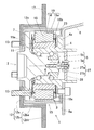
- FIG. 1 is a cross-sectional view of a vehicle power unit according to a first embodiment of the present invention.
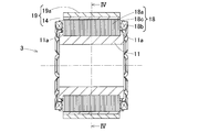
- FIG. 3 is a plan view showing an appearance of an electric motor of the vehicle power unit. It is an axial sectional view of the electric motor.
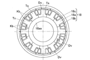
- FIG. 4 is a sectional view taken along line IV-IV of FIG. 3. It is a figure showing the shape of one electromagnetic steel plate of the electric motor.
- FIG. 11 is a perspective view showing an example of a stator assembly using the electromagnetic steel plate or the dust core of FIG. 10.
- FIG. 2 is a block diagram showing a conceptual configuration of a vehicle system of a vehicle including any of the vehicle power units.
- FIG. 13 is a power supply system diagram showing an example of a vehicle equipped with the vehicle system of FIG. 12. It is a figure explaining the notional composition of the system for vehicles of other vehicles provided with the power unit for vehicles. It is a perspective view showing the appearance of a general stator assembly. It is a figure which shows the assembling method of the stator assembly of FIG.
- FIG. 11 is a cross-sectional view of a conventional vehicle power unit.
- FIG. 11 is a cross-sectional view of another conventional vehicle power unit. It is sectional drawing of the other conventional vehicle power unit.
- an electric rotating machine such as an electric motor or a generator and a vehicle power unit or a vehicle device such as a wheel bearing using the electric rotating machine will be described.
- the vehicle power unit 1 includes a wheel bearing 2 and an electric motor 3.
- the wheel bearing 2 has an outer ring 4 which is a fixed ring, a rolling element 6 in a double row, and an inner ring 5 which is a rotating wheel. Grease is sealed in the bearing space between the outer ring 4 and the inner ring 5.
- a vehicle body mounting flange 4a is provided on the outer peripheral surface of the outer ring 4 on the inboard side so as to project radially outward.
- the vehicle body mounting flange 4a is fixed to the knuckle 8 which is a suspension frame component.
- the inner ring 5 has a hub ring 5a and a partial inner ring 5b fitted to the outer peripheral surface of the hub ring 5a on the inboard side.
- the hub wheel 5a has a hub flange 7 at a location that projects more toward the outboard side in the axial direction than the outer wheel 4.
- a brake rotor 12 and a wheel rim are attached to the side surface of the hub flange 7 on the outboard side by a hub bolt 13 in a state of overlapping in the axial direction.
- Tires are attached to the outer circumference of the rim.
- the outboard side the side that is closer to the outside in the vehicle width direction of the vehicle when the vehicle power unit 1 is mounted on the vehicle
- the side that is closer to the center of the vehicle in the vehicle width direction is in. Called the board side.
- the brake 17 is a friction brake including a disc-shaped brake rotor 12 and a brake caliper 16 (FIG. 12).
- the brake rotor 12 has a flat plate portion 12a and an outer peripheral portion 12b.
- the flat plate portion 12 a is an annular flat plate member that overlaps the hub flange 7.
- the outer peripheral portion 12b includes a cylindrical portion 12ba that extends cylindrically from the outer peripheral edge portion of the flat plate-shaped portion 12a to the inboard side, and a flat plate portion 12bb that extends from the inboard side end of the cylindrical portion 12ba to the outer diameter side. And have.
- the brake caliper 16 (FIG.
- the brake caliper 16 (FIG. 12) may be either a hydraulic type or a mechanical type, and may be an electric motor type.
- the motor generator 3 in this example is a motor generator for traveling assistance that can rotate and drive the wheels by generating electricity by rotating the wheels and supplying power.
- the electric motor 3 is an outer rotor type including a stator 18 and a rotor 19 located so as to face the stator 18 outward in the radial direction. Further, the electric motor 3 is of a direct drive type in which the rotor 19 is attached to the inner ring 5 which is the rotating wheel of the wheel bearing 2.
- the electric motor 3 is installed inward in the radial direction from the inner diameter 12c of the brake rotor 12, and is installed in the axial range between the hub flange 7 and the outboard side surface 8a of the knuckle 8.
- the electric motor 3 is, for example, a surface magnet type permanent magnet motor of an outer rotor type, that is, an SPM (Surface Permanent Magnet) synchronous motor (or SPMSM (Surface Permanent Magnet Synchronous Motor)).
- the electric motor 3 may be an IPM (Interior Permanent Magnet) synchronous motor (or IPMSM (Interior Permanent Magnet Synchronous Motor)).
- the electric motor 3 may be a switched reluctance motor.
- the rotor 19 includes a rotor body 19a described below and a plurality of permanent magnets 14 provided on the rotor body 19a.
- the rotor case 15 is made of, for example, a soft magnetic material, and has a bottomed cylindrical shape concentric with the inner ring 5.
- the rotor case 15 has a flat plate-shaped and ring-shaped case bottom portion 15a, and the rotor main body 19a extending from the outer peripheral edge portion of the case bottom portion 15a to the inboard side in a cylindrical shape.
- the case bottom 15a and the rotor body 19a are formed integrally or separately.
- the case bottom portion 15a is sandwiched between the flat plate-shaped portion 12a of the brake rotor 12 and the hub flange 7.
- a plurality of recesses are formed on the inner peripheral surface of the rotor body 19 at regular intervals in the circumferential direction, and the permanent magnets 14 are fitted in the recesses and fixed by adhesion or the like.
- the stator 18 is assembled on the outer peripheral surface of the annular stator support component 11 as described below to form a subassembly.
- the stator support component 11 is made of, for example, a magnetic material. In this case, the magnetic flux of the stator 18 passes through the stator support component 11, and the output of the electric motor 3 is improved.
- the stator support component 11 may be made of an insulating material. In this case, the insulation between the stator support component 11 and the peripheral components is ensured, and for example, it is possible to prevent the short-circuit current when the coil is short-circuited from conducting to the peripheral components.
- the stator support component 11 is a structure in which the stator 18 cannot be inserted from the axial direction because it has flanges 11a and 11a protruding outward in the radial direction at both ends in the axial direction.
- the stator 18 has a stator core 18a, a bobbin 18c inserted into the teeth Ts (FIG. 4) of the stator core 18a, and a stator coil 18b for passing an electric current to generate a magnetic force.
- a stator coil 18b is wound around a tooth Ts (Fig. 4) of the stator core 18a via a bobbin 18c.
- the coil winding method either centralized winding or distributed winding can be used. However, in the case of distributed winding, it is necessary to wind the stator coil 18b after assembling the stator core 18a.
- the stator core 18a includes an annular portion 18aa and a plurality of teeth Ts protruding radially outward from the annular portion 18aa. Teeth Ts extends straight shape, i.e. straight over the tip portion from the proximal portion (Fig. 9 A).
- the stator core 18a is composed of a plurality of stator core divided bodies Dv having the teeth Ts divided in the circumferential direction by the annular portion 18aa, and the stator core divided bodies Dv are located on both sides of the divided circumferential direction in the radial direction.
- a fitting portion Kb is provided which is inserted into and fitted into the.
- the fitting portion Kb has an uneven portion Kba in which the contact surfaces of the stator core divided bodies Dv adjacent to each other in the circumferential direction have an uneven shape, and the concave and convex portions adjacent to each other in the circumferential direction.
- the portions Kba are fitted together to form an annular portion 18aa.
- the stator core divided body Dv is formed by stacking a single asymmetrical electromagnetic steel plate 20 with the front and back reversed.
- the electromagnetic steel sheet 20 of this example has a base end portion 20a on one side (left side in FIG. 5) in the circumferential direction forming a part of the annular portion 18aa (FIG. 4) centered on the teeth Ts.
- the electromagnetic steel sheet 20 is asymmetrical by being formed shorter than the other base end portion 20b.
- the uneven portion Kba is formed by sequentially laminating one left-right asymmetrical magnetic steel sheet 20 with a constant product thickness by reversing the front and back sides of each stator core divided body.
- the electromagnetic steel plates 20 laminated to have a desired laminated thickness are joined to each other by caulking or bonding.
- a plurality of stator core divided bodies Dv are assembled from the outside to the inside in the radial direction on the outer peripheral surface of the annular stator support component 11, and the unevenness is a rectangular groove adjacent in the circumferential direction.
- the stator 18 has an annular shape.
- a plurality of stator core divided bodies Dv are assembled to the outer peripheral surface of the stator support component 11 from the radial direction (FIG. 6).
- the fitting portion Kb between the teeth Ts and Ts is caulked from the radial direction and joined by welding or adhesion (FIG. 7).
- the bobbin 18c and the stator coil 18b are inserted into the teeth Ts from the radial direction, and the stator coil 18b is connected (FIG. 8).
- the rotor and peripheral parts are assembled to form an electric motor 3.
- the vehicle power unit 1 is provided with a rotation detector 27.
- the rotation detector 27 detects the rotation angle or rotation speed of the inner ring 5 with respect to the outer ring 4 in order to control the rotation of the electric motor 3 for traveling assistance.
- the rotation detector 27 has a detected part 27a attached to the detected part holding member and the like, and a sensor part 27b for detecting the detected part 27a.
- the sensor portion 27b is fixed to the inner peripheral surface of the outer ring 4 on the inboard side via the sensor fixing member 28.
- a resolver for example, is applied as the rotation detector 27. It should be noted that the rotation detector 27 is not limited to a resolver, and may be, for example, an encoder, a pulsar ring, a hall sensor, or the like, and may be mounted in one or more or in combination.
- a plurality of stator core divided bodies Dv are arranged from the outer periphery of the stator support component 11 with respect to the stator support component 11 through which the stator 18 cannot be inserted from the axial direction, and the stator core divided body Dv
- the divided fitting portions Kb on both sides in the circumferential direction are inserted into each other in the radial direction and fitted. Therefore, the assembly in which the plurality of stator core divided bodies Dv are assembled can be attached to the bearing outer ring or the like. Since the plurality of stator core divided bodies Dv can be assembled in the radial direction in this manner, the versatility of the electric motor 3 can be enhanced. Therefore, it is possible to secure the volume of the stator 18 even if there is a restriction on the dimensions, and it is possible to realize a sufficient electric motor output.
- the teeth Ts extends straight from the base end portion to the tip end portion, the teeth Ts, Ts are assembled in an annular shape and the bobbin 18c and the stator coil 18b are attached to the teeth Ts.
- a caulking component or an adhesive application nozzle or the like can easily reach the fitting portion Kb between them.
- the stator coil 18b can be inserted into the teeth Ts after the stator 18 is assembled in an annular shape, which facilitates manufacturing. Therefore, the assemblability of the electric motor 3 can be improved.
- stator core split body Dv is formed by laminating electromagnetic steel sheets 20 that are asymmetrical in the front and rear sides by reversing the front and back sides, the electromagnetic steel sheets 20 manufactured from a press die having one shape are used on the circumference.
- the fitting portion Kb can be formed, which is inexpensive, easy to assemble, and has a strong structure.
- the teeth Ts are provided with T-shaped flange portions Rb protruding in an arc shape on both sides in the circumferential direction from the tip portion. May be good.
- a bobbin having a shape divided in the axial direction is attached after assembling the stator and coiled, or the tooth Ts is coiled first and then bonded or lightly press-fitted.
- the collar portion is also referred to as “rib”.
- the facing area between the tip of the stator and the magnet can be increased as compared with straight-shaped teeth, the output of the electric motor can be improved, and the cogging torque can be reduced.
- the presence of the flange portion Rb can prevent the stator coil from moving in the radial direction and coming off the tooth Ts.
- winding the stator coil in the state of the stator core split body facilitates coil winding.
- a nozzle (not shown) for winding the stator coil may interfere with the teeth (particularly the collar portion), but the stator core is divided.
- the stator core divided body Dv has a plurality of types having different shapes in the portion forming the fitting portion and the other portion.
- the electromagnetic steel plates 20A, 20B, and 20C (three kinds in this example) may be laminated.
- the area of the fitting portion Kb is increased, and the strength when assembled in an annular shape can be increased.
- the type of the electromagnetic steel sheet may be two types or four or more types.
- stator core divided bodies Dv are laminated by the electromagnetic steel sheets, but the stator core divided bodies Dv are not limited to the laminated electromagnetic steel sheets.
- the stator core divided body Dv may be an integrally molded material (compacted powder) At such as a integrally compacted powder magnetic core.
- FIG. 12 is a block diagram showing a conceptual configuration of a vehicle system using any of the vehicle power units 1.
- the vehicle power unit 1 is mounted on the driven wheel 10B in the vehicle 30 having the driven wheel 10B that is mechanically unconnected to the main drive source.
- the wheel bearing 2 (FIG. 1) in the vehicle power unit 1 is a bearing that supports the driven wheel 10B.
- the main drive source 35 is an internal combustion engine such as a gasoline engine or a diesel engine, a motor generator (electric motor), or a hybrid type drive source in which both are combined.
- the "motor generator” is referred to as an electric motor capable of generating electricity by applying rotation.
- the vehicle 30 is a front-wheel drive vehicle in which the front wheels are the drive wheels 10A and the rear wheels are the driven wheels 10B, and the main drive source 35 has an internal combustion engine 35a and an electric generator 35b on the drive wheel side. It is a hybrid vehicle (hereinafter sometimes referred to as "HEV").
- HEV hybrid vehicle
- Mild hybrids are a type in which the main drive source is an internal combustion engine and the motor mainly assists driving when starting or accelerating, and EV. In the (electric vehicle) mode, it is distinguished from the strong hybrid because it can not run for a long time even if it can run normally.
- the internal combustion engine 35a in the example of FIG. 12 is connected to the drive shaft of the drive wheel 10A via the clutch 36 and the speed reducer 37, and the drive wheel side motor generator 35b is connected to the speed reducer 37.
- This vehicle system includes an electric motor 3 which is a motor generator for traveling assistance that rotationally drives the driven wheel 10B, an individual control means 39 that controls the electric motor 3, and the individual control means provided in the upper ECU 40. 39, and an individual motor/generator command means 45 for outputting a command for controlling driving and regeneration.
- the electric motor 3 is connected to the power storage means.
- a battery storage battery
- a capacitor a capacitor, or the like can be used as the power storage unit, and its type and mounting position on the vehicle 30 are not limited, but in this embodiment, the low-voltage battery 50 mounted on the vehicle 30 and
- the medium voltage battery 49 is the medium voltage battery 49.
- the electric motor 3 for the driven wheels is a direct drive motor that does not use a transmission.
- the electric motor 3 acts as an electric motor by supplying electric power, and also acts as a generator that converts the kinetic energy of the vehicle 30 into electric power.
- the rotor 19 (FIG. 1) is attached to the inner ring 5 (FIG. 1) which is a hub wheel, when a current is applied to the electric motor 3, the inner ring 5 (FIG. 1) is rotationally driven, and conversely, electric power regeneration. Regenerative power can sometimes be obtained by loading an induced voltage.
- the host ECU 40 is a unit that performs integrated control of the vehicle 30, and includes a torque command generation unit 43.
- the torque command generating means 43 generates a torque command according to the operation amount signals input from the accelerator operating means 56 such as the accelerator pedal and the brake operating means 57 such as the brake pedal.
- the vehicle 30 includes an internal combustion engine 35a and a motor generator 35b on the drive wheel side as a main drive source 35, and also includes two motors 3 and 3 for driving two driven wheels 10B and 10B, respectively.
- Torque command distribution means 44 is provided in the upper ECU 40 to distribute the torque command distribution means 44 according to the rules defined in the drive sources 35a, 35b, 3, 3 respectively.
- the torque command for the internal combustion engine 35a is transmitted to the internal combustion engine control means 47 and used for the valve opening control and the like by the internal combustion engine control means 47.
- the torque command for the motor generator 35b on the drive wheel side is transmitted to the motor generator control means 48 on the drive wheel side and executed.
- the torque command for the electric motors 3 and 3 on the driven wheel side is transmitted to the individual control means 39 and 39.
- the portion that outputs to the individual control means 39, 39 is referred to as the individual motor generator command means 45.
- the individual motor generator command means 45 also has a function of giving a torque command to the individual control means 39, which is a command of a braking force in which the electric motor 3 shares braking by regenerative braking, in response to a signal of the operation amount of the brake operating means 57. Be prepared.
- the individual control means 39 is an inverter device, and includes an inverter 41 that converts the DC power of the medium voltage battery 49 into a three-phase AC voltage, and a control unit 42 that controls the output of the inverter 41 by PWM control or the like by the torque command or the like.
- the inverter 41 includes a bridge circuit (not shown) including semiconductor switching elements and the like, and a charging circuit (not shown) for charging the medium voltage battery 49 with the regenerative power of the electric motor 3.
- the individual control means 39 is provided separately for the two electric motors 3, 3, but may be housed in one housing and the control unit 42 may be shared by both the individual control means 39, 39. ..
- FIG. 13 is a power supply system diagram showing an example of a vehicle equipped with the vehicle system shown in FIG.
- a low-voltage battery 50 and a medium-voltage battery 49 are provided as batteries, and the both batteries 49, 50 are connected via a DC/DC converter 51.
- the drive wheel-side motor generator 35b in FIG. 12 is connected to the medium power system in parallel with the driven wheel-side electric motor 3.
- a low voltage load 52 is connected to the low voltage system, and a medium voltage load 53 is connected to the medium voltage system.
- the low-voltage battery 50 is a battery generally used in various automobiles as a power source for a control system, and is set to 12V or 24V, for example.
- the low-voltage load 52 includes basic components such as a starter motor of the internal combustion engine 35a, lights, the host ECU 40, and other ECUs (not shown).
- the low voltage battery 50 may be referred to as an auxiliary battery for electrical accessories, and the medium voltage battery 49 may be referred to as an auxiliary battery for an electric system.
- the medium-voltage battery 49 has a higher voltage than the low-voltage battery 50 and is lower than the high-voltage battery (100 V or more, for example, about 200 to 400 V) used for strong hybrid vehicles and the like, and has an influence on the human body due to electric shock during work.
- a 48V battery which has a voltage that does not pose a problem and has been used in mild hybrids in recent years, is preferable.
- the medium voltage battery 49 such as a 48V battery can be relatively easily mounted on a vehicle equipped with a conventional internal combustion engine, and can reduce fuel consumption by power assist and regeneration by electric power as a mild hybrid.
- the medium-voltage load 53 of the 48V system is the accessory part, and includes a power assist motor that is the electric motor 3 on the drive wheel side, an electric pump, an electric power steering, a supercharger, and an air compressor.
- This vehicle system is suitable for accessory parts of such mild hybrid vehicles, and is applied as power assist and power regeneration parts.
- CMG crankshaft Motor driven Generator
- GMG Global System Motor driven Generator
- belt drive type starter motor belt drive type starter motor (neither is shown), etc.
- power assist or regeneration is performed on the internal combustion engine or the power plant, the efficiency of the transmission device and the speed reducer is affected.
- the vehicle system of this embodiment is mounted on the driven wheels 10B, it is separated from the main drive sources such as the internal combustion engine 35a and the electric motor (not shown), and during power regeneration. Can directly use the kinetic energy of the car body. Further, when mounting a CMG, GMG, belt-driven starter motor, etc., it is necessary to incorporate it in consideration from the design stage of the vehicle 30, and it is difficult to retrofit it, but this vehicle system that fits in the driven wheel 10B.
- the electric motor 3 can be attached to a completed vehicle with the same man-hours as the parts replacement, and a 48V system can be configured even for a completed vehicle having only the internal combustion engine 35a.
- a vehicle equipped with the vehicle system of this embodiment may be equipped with another auxiliary drive motor generator 35b as in the example of FIG. In that case, the amount of power assist and the amount of regenerative electric power for the vehicle 30 can be increased, which further contributes to reduction of fuel consumption.
- FIG. 14 shows an example in which the vehicle power unit 1 according to any one of the embodiments is applied to the drive wheels 10A that are the front wheels and the driven wheels 10B that are the rear wheels.
- the drive wheel 10A is driven by a main drive source 35 composed of an internal combustion engine via a clutch 36 and a speed reducer 37.
- a vehicle power unit 1 is installed for supporting and assisting each drive wheel 10A and driven wheel 10B. As described above, the vehicle power unit 1 can be applied not only to the driven wheels 10B but also to the driving wheels 10A.
- the vehicle system shown in FIG. 12 has a function of generating electric power, but may be a system that is not rotationally driven by power supply.
- This vehicle system is equipped with a generator-equipped wheel bearing device including a generator 3 that also does not serve as a motor and a wheel bearing 2.
- the wheel bearing device with a generator has the same configuration as the vehicle power device of any of the embodiments except for the electric motor.
- the braking force can be generated by storing the regenerative power generated by the generator 3 in the medium voltage battery 49. Braking performance can also be improved by using or using it in combination with the mechanical brake operating means 57.
- the individual control means 39 can be configured as an AC/DC converter device (not shown) instead of an inverter device.
- the AC/DC converter device has a function of charging the regenerative power of the generator 3 into the medium voltage battery 49 by converting a three-phase AC voltage into a DC voltage, and a control method is easy as compared with an inverter, Miniaturization is possible.
- the vehicle power unit and the bearing for wheels with a generator in the present application include a hub ring in which one partial inner ring is fitted as a rotating wheel, and is composed of an outer ring which is a fixed ring and a fitting body of the hub ring and the partial inner ring.
- a structure including a hub having a hub flange and a member having a raceway surface of a rolling element is a rotating wheel in claims.
- it may be a first generation structure including an outer ring which is mainly a fixed ring and an inner ring fitted to the outer peripheral surface of a hub having a hub flange.
- the combination of the hub and the inner ring corresponds to the "rotating ring" in the claims.
- the electric motor can also be applied to a motor for home appliances, an industrial motor, and the like.
- the generator can be applied to a wind power generator or a hydro power generator.
Landscapes
- Engineering & Computer Science (AREA)
- Power Engineering (AREA)
- Iron Core Of Rotating Electric Machines (AREA)
- Connection Of Motors, Electrical Generators, Mechanical Devices, And The Like (AREA)
- Permanent Magnet Type Synchronous Machine (AREA)
Abstract
軸方向からステータを挿通することができない構造体に対して、組み立てることができ、出力の向上を図ることができる電動機およびこの電動機を備えた車両用動力装置、発電機およびこの発電機を備えた発電機付車輪用軸受を提供する。この電動機(3)は、ステータコア(18a)およびステータコイルを有するステータと、ステータに対し半径方向外方に対向するロータとを備えたアウターロータ型である。ステータコア(18a)は、円環部と、円環部から半径方向外方に突出しステータコイルが巻回される円周方向複数のティース(Ts)とを備える。ステータコア(18a)は、円環部で円周方向に分割されてそれぞれティース(Ts)を有する複数のステータコア分割体(Dv)から成り、これらステータコア分割体(Dv)の分割された円周方向両側部に、互いに半径方向に挿入して嵌合される嵌合部(Kb)が設けられている。
Description
本出願は、2019年3月7日出願の特願2019-041576の優先権を主張するものであり、その全体を参照により本願の一部をなすものとして引用する。
この発明は、自動車等に設置される電動機およびこの電動機を備えた車両用動力装置、発電機およびこの発電機を備えた発電機付車輪用軸受に関する。
一般的なラジアル構造の三相永久磁石同期モータは、ステータ構造として、環状の部材にティースが等配された構造を持つ。ティースにコイルが巻かれ、コイルは三相の動力線を結線して構成されている(例えば、特許文献1,2)。
ラジアルモータは円環状のステータ構造を持つ。ラジアルモータの一般的な組立方法は、ステータコアの内周にステータ支持部品を軸方向に挿通して組み立てる。
図15は、一般的なアウターロータ型モータのステータアッシの外観を示す斜視図、図16は前記ステータアッシの組立方法を示す図である。図15および図16に示すように、全周に等配なティースTsを持つ円環状の電磁鋼板20を積層してステータコアを構成し、ステータ支持部材11にステータコアを軸方向から挿通することでステータアッシとする。
しかし、ステータコアを軸方向から挿通することができない構造では、ラジアルモータを組み立てることができない。
図15は、一般的なアウターロータ型モータのステータアッシの外観を示す斜視図、図16は前記ステータアッシの組立方法を示す図である。図15および図16に示すように、全周に等配なティースTsを持つ円環状の電磁鋼板20を積層してステータコアを構成し、ステータ支持部材11にステータコアを軸方向から挿通することでステータアッシとする。
しかし、ステータコアを軸方向から挿通することができない構造では、ラジアルモータを組み立てることができない。
本件出願人は、図17に示すように、車輪用軸受60の外周部に電動発電機61を組み込んだものを提案している(例えば、特許文献3)。しかし、前記電動発電機61として、図15、図16に示す一般的なステータアッシの組立方法のモータを採用する場合は、図17に示すように、車体固定部への固定ボルトの挿通孔よりも外径部にモータを配置する必要があり、モータの内径側が狭くなり、且つモータの外径側はブレーキロータの円筒部よりも小さくする必要がある。このため、モータ出力の向上が見込めない。
一方、図18のような構造であれば、限られた空間を有効に活用できるが、軸受を組み立てる前に外輪62にモータステータ63を取り付ける必要があり、組み付け性が悪い。
図19のように、車輪用軸受64とモータステータ65との間に、車体への固定部を持った中間リング66を介在する技術(特願2018-097100)も提案されているが、部品点数の増加等が懸念される。
図19のように、車輪用軸受64とモータステータ65との間に、車体への固定部を持った中間リング66を介在する技術(特願2018-097100)も提案されているが、部品点数の増加等が懸念される。
この発明の目的は、軸方向からステータを挿通することができない構造体に対して、組み立てることができ、出力の向上を図ることができる電動機およびこの電動機を備えた車両用動力装置、発電機およびこの発電機を備えた発電機付車輪用軸受を提供することである。
この発明の電動機は、ステータコアおよびこのステータコアに巻回されたステータコイルを有するステータと、このステータに対し半径方向外方に対向するロータとを備えたアウターロータ型であり、前記ステータコアは、円環部と、この円環部から半径方向外方に突出し前記ステータコイルが巻回される円周方向複数のティースとを備えた電動機であって、
前記ステータコアは、前記円環部で円周方向に分割されてそれぞれ前記ティースを有する複数のステータコア分割体から成り、これらステータコア分割体の前記分割された円周方向両側部に、互いに半径方向に挿入して嵌合される嵌合部が設けられている。
前記ステータコアは、前記円環部で円周方向に分割されてそれぞれ前記ティースを有する複数のステータコア分割体から成り、これらステータコア分割体の前記分割された円周方向両側部に、互いに半径方向に挿入して嵌合される嵌合部が設けられている。
この構成によると、軸方向からステータを挿通することができない構造体に対し、複数のステータコア分割体を前記構造体の外周から配置し、このステータコア分割体の分割された円周方向両側部にある嵌合部を互いに半径方向に挿入して嵌合する。よって、複数のステータコア分割体が組み付けられた組立品を、軸受外輪等に取り付けることができる。このように複数のステータコア分割体を半径方向から組み付けることができるため、電動機の汎用性を高めることができる。したがって、寸法の制約がある場合でもステータの体積を確保することが可能であり、十分な電動機出力を実現できる。
前記ティースは、基端部分から先端部分にわたって直線状に延びてもよい。この場合、複数のステータコア分割体を組み付け、ステータコイル等をティースに装着する前の工程において、ティース間の嵌合部に、例えば、加締め部品または接着剤の塗布ノズル等を容易に到達させることができる。したがって電動機の組立性を向上することができる。
前記ティースは、先端部分から円周方向両側に円弧状に突出する鍔部が設けられていてもよい。この場合、直線状のティースよりも、ステータ先端と磁石との対向面積を増やすことができ、電動機の出力向上を図れ、且つコギングトルクを低減し得る。また鍔部があることで、ステータコイルが径方向に移動してティースから外れることを防止することができる。
前記嵌合部は、円周方向に隣接する前記ステータコア分割体同士の当接面が円周方向に凹凸形状となる凹凸部分を有し、円周方向に隣接する前記凹凸部分が互いに嵌め合わされて前記円環部を構成してもよい。この場合、円周方向に隣接する凹凸部分を互いに嵌め合わすことで、ステータコアを容易に組み付けることができる。その後、嵌合部を溶接または接着等により接合することが可能となる。
前記ステータコア分割体は、前記嵌合部を構成する部分と他の部分とで互いに形状の異なる電磁鋼板が積層されたものであってもよい。この形状の異なる電磁鋼板が積層されたステータコア分割体は、嵌合部の面積が増加し、円環状に組み立てた際の強度を増すことができる。
前記ステータコア分割体は、正面視で左右非対称の電磁鋼板が表裏逆転させて積層されたものであってもよい。この場合、一つの形状のプレス金型から製造される電磁鋼板を用いて、円周上で嵌合部を構成することができ、安価で且つ組み立てが容易で強固な構成となる。
前記ステータコア分割体は、一体成形された圧粉体であってもよい。この場合、金型によりステータコア分割体を製作すればよく、電磁鋼板を積層したものより量産性を高めることが可能となる。
この発明の車両用動力装置は、固定輪およびこの固定輪に転動体を介して回転自在に支持された回転輪を有し、この回転輪に設けられたハブフランジに車両の車輪が取付けられる車輪用軸受と、この車輪用軸受に取付けられた前記いずれかに記載の発明の電動機と、を備え、前記固定輪に前記ステータが取付けられ、前記回転輪に前記ロータが取付けられている。この構成によると、車両用動力装置の限られた空間に電動機を収めることができ、また車輪用軸受の組み立て後に固定輪にステータを取り付けることができる。したがって、軸受を組み立てる前に固定輪にステータを取り付ける従来例よりも、組み付け性の向上を図れる。
この発明の発電機は、ステータコアおよびこのステータコアに巻回されたステータコイルを有するステータと、このステータに対し半径方向外方に対向するロータとを備えたアウターロータ型であり、前記ステータコアは、円環部と、この円環部から半径方向外方に突出し前記ステータコイルが巻回される円周方向複数のティースとを備えた発電機であって、
前記ステータコアは、前記円環部で円周方向に分割されてそれぞれ前記ティースを有する複数のステータコア分割体から成り、これらステータコア分割体の前記分割された円周方向両側部に、互いに半径方向に挿入して嵌合される嵌合部が設けられている。
前記ステータコアは、前記円環部で円周方向に分割されてそれぞれ前記ティースを有する複数のステータコア分割体から成り、これらステータコア分割体の前記分割された円周方向両側部に、互いに半径方向に挿入して嵌合される嵌合部が設けられている。
この構成によると、軸方向からステータを挿通することができない構造体に対し、複数のステータコア分割体の分割された円周方向両側部にある嵌合部を互いに半径方向に挿入して嵌合する。よって、複数のステータコア分割体が組み付けられた組立品を、軸受外輪等に取り付けることができる。このように複数のステータコア分割体を半径方向から組み付けることができるため、発電機の汎用性を高めることができる。したがって、寸法の制約がある場合でもステータの体積を確保することが可能であり、十分な発電機出力を実現できる。
この発明の発電機付き車輪用軸受装置は、固定輪およびこの固定輪に転動体を介して回転自在に支持された回転輪を有し、この回転輪に設けられたハブフランジに車両の車輪が取付けられる車輪用軸受と、この車輪用軸受に取付けられた前記記載の発明の発電機と、を備え、前記固定輪に前記ステータが取付けられ、前記回転輪に前記ロータが取付けられている。この構成によると、発電機付き車輪用軸受装置の限られた空間に発電機を収めることができ、また車輪用軸受の組み立て後に固定輪にステータを取り付けることができる。したがって、軸受を組み立てる前に固定輪にステータを取り付ける従来例よりも、組み付け性の向上を図れる。
請求の範囲および/または明細書および/または図面に開示された少なくとも2つの構成のどのような組合せも、この発明に含まれる。特に、請求の範囲の各請求項の2つ以上のどのような組合せも、この発明に含まれる。
この発明は、添付の図面を参考にした以下の好適な実施形態の説明から、より明瞭に理解されるであろう。しかしながら、実施形態および図面は単なる図示および説明のためのものであり、この発明の範囲を定めるために利用されるべきものではない。この発明の範囲は添付の請求の範囲によって定まる。添付図面において、複数の図面における同一の符号は、同一または相当する部分を示す。
この発明の第1の実施形態に係る車両用動力装置の断面図である。
同車両用動力装置の電動機の外観を表す平面図である。
同電動機の軸方向断面図である。
図3のIV-IV線断面図である。
同電動機の電磁鋼板一枚の形状を表す図である。
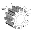
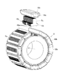
同電動機のステータの組立方法を示す斜視図である。
同ステータの円環部の接合方法を示す斜視図である。
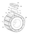
ステータコイルおよびボビンの挿入方法を示す斜視図である。
ティース先端の形状例を示す図である。
第2の実施形態に係るティース先端の形状例を示す図である。
第3の実施形態に係る複数種類の電磁鋼板の形状例を示す図である。
図10の電磁鋼板または圧粉磁心を利用したステータアッシの例を示す斜視図である。
いずれかの車両用動力装置を備えた車両の車両用システムの概念構成を示すブロック図である。
図12の車両用システムを搭載した車両の一例となる電源系統図である。
同車両用動力装置を備えた他の車両の車両用システムの概念構成を説明する図である。
一般的なステータアッシの外観を示す斜視図である。
図15のステータアッシの組立方法を示す図である。
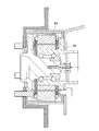
従来例の車両用動力装置の断面図である。
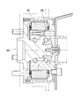
他の従来例の車両用動力装置の断面図である。
その他の従来例の車両用動力装置の断面図である。
以下の実施形態では、電動機または発電機のような電気回転機と、これを用いた車両用動力装置または車輪用軸受のような車両用装置について説明する。
[第1の実施形態]
この発明の第1の実施形態に係る車両用動力装置を図1ないし図9Aと共に説明する。
図1に示すように、この車両用動力装置1は、車輪用軸受2と、電動機3とを備える。
<車輪用軸受2について>
車輪用軸受2は、固定輪である外輪4と、複列の転動体6と、回転輪である内輪5とを有する。外輪4と内輪5との間の軸受空間には、グリースが封入されている。外輪4のインボード側の外周面には、半径方向外方に突出する車体取付フランジ4aが設けられている。足回りフレーム部品であるナックル8に、車体取付フランジ4aが固定される。
内輪5は、ハブ輪5aと、このハブ輪5aのインボード側の外周面に嵌合された部分内輪5bとを有する。ハブ輪5aは、外輪4よりも軸方向のアウトボード側に突出した箇所にハブフランジ7を有する。
この発明の第1の実施形態に係る車両用動力装置を図1ないし図9Aと共に説明する。
図1に示すように、この車両用動力装置1は、車輪用軸受2と、電動機3とを備える。
<車輪用軸受2について>
車輪用軸受2は、固定輪である外輪4と、複列の転動体6と、回転輪である内輪5とを有する。外輪4と内輪5との間の軸受空間には、グリースが封入されている。外輪4のインボード側の外周面には、半径方向外方に突出する車体取付フランジ4aが設けられている。足回りフレーム部品であるナックル8に、車体取付フランジ4aが固定される。
内輪5は、ハブ輪5aと、このハブ輪5aのインボード側の外周面に嵌合された部分内輪5bとを有する。ハブ輪5aは、外輪4よりも軸方向のアウトボード側に突出した箇所にハブフランジ7を有する。
ハブフランジ7のアウトボード側の側面には、ブレーキロータ12と図示外の車輪のリムとが軸方向に重なった状態で、ハブボルト13により取付けられている。前記リムの外周に図示外のタイヤが取付けられている。
なおこの明細書において、車両用動力装置1が車両に搭載された状態で車両の車幅方向の外側寄りとなる側をアウトボード側と呼び、車両の車幅方向の中央寄りとなる側をインボード側と呼ぶ。
なおこの明細書において、車両用動力装置1が車両に搭載された状態で車両の車幅方向の外側寄りとなる側をアウトボード側と呼び、車両の車幅方向の中央寄りとなる側をインボード側と呼ぶ。
<ブレーキ17について>
ブレーキ17は、ディスク状のブレーキロータ12と、ブレーキキャリパ16(図12)とを備える摩擦ブレーキである。ブレーキロータ12は、平板状部12aと、外周部12bとを有する。平板状部12aは、ハブフランジ7に重なる環状で且つ平板状の部材である。外周部12bは、平板状部12aの外周縁部からインボード側に円筒状に延びる円筒状部12baと、この円筒状部12baのインボード側端から外径側に平板状に延びる平板部12bbとを有する。
前記ブレーキキャリパ16(図12)は、車両における足回りフレーム部品であるナックル8に取付けられ、前記平板部12bbを挟み付ける摩擦パッド(図示せず)を有する。前記ブレーキキャリパ16(図12)は、油圧式および機械式のいずれであってもよく、また電動モータ式であってもよい。
ブレーキ17は、ディスク状のブレーキロータ12と、ブレーキキャリパ16(図12)とを備える摩擦ブレーキである。ブレーキロータ12は、平板状部12aと、外周部12bとを有する。平板状部12aは、ハブフランジ7に重なる環状で且つ平板状の部材である。外周部12bは、平板状部12aの外周縁部からインボード側に円筒状に延びる円筒状部12baと、この円筒状部12baのインボード側端から外径側に平板状に延びる平板部12bbとを有する。
前記ブレーキキャリパ16(図12)は、車両における足回りフレーム部品であるナックル8に取付けられ、前記平板部12bbを挟み付ける摩擦パッド(図示せず)を有する。前記ブレーキキャリパ16(図12)は、油圧式および機械式のいずれであってもよく、また電動モータ式であってもよい。
<電動機3について>
この例の電動機3は、車輪の回転で発電を行い、給電されることによって車輪を回転駆動可能な走行補助用の電動発電機である。電動機3は、ステータ18と、このステータ18に対し半径方向外方に対向して位置するロータ19とを備えたアウターロータ型である。また、電動機3は、ロータ19が車輪用軸受2の回転輪である内輪5に取付けられたダイレクトドライブ形式である。
この例の電動機3は、車輪の回転で発電を行い、給電されることによって車輪を回転駆動可能な走行補助用の電動発電機である。電動機3は、ステータ18と、このステータ18に対し半径方向外方に対向して位置するロータ19とを備えたアウターロータ型である。また、電動機3は、ロータ19が車輪用軸受2の回転輪である内輪5に取付けられたダイレクトドライブ形式である。
この電動機3は、ブレーキロータ12の内径12cよりも半径方向内方に設置され、且つ、ハブフランジ7と、ナックル8のアウトボード側面8aとの間の軸方向範囲に設置されている。電動機3は、アウターロータ型の例えば表面磁石型永久磁石モータ、すなわちSPM(Surface Permanent Magnet)同期モータ(もしくはSPMSM(Surface Permanent Magnet Synchronous Motor)と標記)である。電動機3は、IPM(Interior Permanent Magnet)同期モータ(もしくはIPMSM(Interior Permanent Magnet Synchronous Motor)と標記)でもよい。その他電動機3は、スイッチトリラクタンスモータ(Switched reluctance motor) であってもよい。
ロータ19は、後述するロータ本体19aと、このロータ本体19aに設けられる複数の永久磁石14とを備える。ロータケース15は、例えば、軟磁性材料から成り、内輪5と同心の有底円筒状である。このロータケース15は、平板状で且つ環状のケース底部15aと、このケース底部15aの外周縁部からインボード側に円筒状に延びる前記ロータ本体19aとを有する。これらケース底部15aとロータ本体19aとは一体もしくは別体で形成されている。ケース底部15aは、ブレーキロータ12の平板状部12aと、ハブフランジ7との間に挟まれる。ロータ本体19の内周面に円周方向一定間隔おきに複数の凹み部が形成され、各凹み部に永久磁石14が嵌まり込んで接着等により固定されている。
図2および図3に示すように、ステータ18は、円環状のステータ支持部品11の外周面に、後述のように組み付けられて準組立品とされている。ステータ支持部品11は、例えば磁性材で構成されている。この場合、ステータ18の磁束がステータ支持部品11内を通り、電動機3の出力が向上する。ステータ支持部品11は、絶縁材で構成されていてもよい。この場合、ステータ支持部品11と周囲部品との絶縁が確保され、例えば、コイルショート時の短絡電流が周囲部品に導通することを防止し得る。
前記ステータ支持部品11は、軸方向両端部に半径方向外方に突出するフランジ11a,11aを有するため、軸方向からステータ18を挿通することができない構造体である。ステータ18は、ステータコア18aと、このステータコア18aのティースTs(図4)に挿入されたボビン18cと、電流を流し磁力を発生させるためのステータコイル18bとを有する。ステータコア18aのティースTs(図4)に、ボビン18cを介してステータコイル18bが巻回されている。コイル巻線の方式は、集中巻き、分布巻きのいずれの方法も可能である。但し、分布巻きの場合は、ステータコア18aを組み立てた後にステータコイル18bを巻く必要がある。
図4に示すように、ステータコア18aは、円環部18aaと、この円環部18aaから半径方向外方に放射状に突出する複数のティースTsとを備える。ティースTsは、基端部分から先端部分にわたってストレート形状つまり直線状に延びる(図9A)。ステータコア18aは、円環部18aaで円周方向に分割されて前記ティースTsを有する複数のステータコア分割体Dvから成り、これらステータコア分割体Dvの前記分割された円周方向両側部に、互いに半径方向に挿入して嵌合される嵌合部Kbが設けられている。
図4および図6に示すように、嵌合部Kbは、円周方向に隣接するステータコア分割体Dv同士の当接面が凹凸形状となる凹凸部分Kbaを有し、円周方向に隣接する凹凸部分Kbaが互いに嵌め合わされて円環部18aaを構成する。図5および図6に示すように、ステータコア分割体Dvは、左右非対称の一枚の電磁鋼板20が表裏逆転させて積層されたものである。この例の電磁鋼板20は、図5に示す正面視において、ティースTsを中心として、円環部18aa(図4)の一部を成す円周方向一方(図5左側)の基端部20aが他方の基端部20bよりも短く形成されることで左右非対称の電磁鋼板20を構成する。
図5および図6に示すように、各ステータコア分割体につき、左右非対称の一枚の電磁鋼板20を一定の積厚で表裏を逆転させて順次積層することで、凹凸部分Kbaが形成される。所望の積厚に積層された電磁鋼板20は、加締めまたは接着により相互に接合されている。
図6および図7に示すように、円環状のステータ支持部品11の外周面に、複数のステータコア分割体Dvを半径方向外方から内方に組み付け、円周方向に隣接する矩形溝である凹凸部分Kbaが互いに嵌合することで円環形状のステータ18となる。
図6および図7に示すように、円環状のステータ支持部品11の外周面に、複数のステータコア分割体Dvを半径方向外方から内方に組み付け、円周方向に隣接する矩形溝である凹凸部分Kbaが互いに嵌合することで円環形状のステータ18となる。
<組立手順について>
(1)ステータ支持部品11の外周面に対し、複数のステータコア分割体Dvを径方向から組み付ける(図6)。
(2)ティースTs,Ts間の嵌合部Kbを径方向から加締め、溶接または接着などにより接合する(図7)。
(3)ティースTsに径方向からボビン18cおよびステータコイル18bを挿入し、ステータコイル18bの結線を行う(図8)。
(4)その後、ロータおよび周辺部品を組み立てて電動機3とする。
(1)ステータ支持部品11の外周面に対し、複数のステータコア分割体Dvを径方向から組み付ける(図6)。
(2)ティースTs,Ts間の嵌合部Kbを径方向から加締め、溶接または接着などにより接合する(図7)。
(3)ティースTsに径方向からボビン18cおよびステータコイル18bを挿入し、ステータコイル18bの結線を行う(図8)。
(4)その後、ロータおよび周辺部品を組み立てて電動機3とする。
<シール構造について>
図1に示すように、ロータケース15のインボード側の内周面と、車体取付フランジ4aの外周面との間には、電動機3および車輪用軸受2内部への水および異物の侵入を防ぐシール部材23が配置されている。
図1に示すように、ロータケース15のインボード側の内周面と、車体取付フランジ4aの外周面との間には、電動機3および車輪用軸受2内部への水および異物の侵入を防ぐシール部材23が配置されている。
<回転検出器27について>
この車両用動力装置1には、回転検出器27が設けられている。この回転検出器27は、走行補助用の電動機3の回転を制御するために、外輪4に対する内輪5の回転角度または回転速度を検出する。回転検出器27は、被検出部保持部材等に取付けられた被検出部27aと、この被検出部27aを検出するセンサ部27bとを有する。外輪4のインボード側の内周面に、センサ固定部材28を介してセンサ部27bが固定されている。この回転検出器27として例えばレゾルバが適用される。なお回転検出器27としては、レゾルバに限定されるものではなく、例えば、エンコーダ、パルサーリングあるいはホールセンサなど形式を問わず採用可能で、それぞれを1つ以上もしくは組み合わせて搭載してもよい。
この車両用動力装置1には、回転検出器27が設けられている。この回転検出器27は、走行補助用の電動機3の回転を制御するために、外輪4に対する内輪5の回転角度または回転速度を検出する。回転検出器27は、被検出部保持部材等に取付けられた被検出部27aと、この被検出部27aを検出するセンサ部27bとを有する。外輪4のインボード側の内周面に、センサ固定部材28を介してセンサ部27bが固定されている。この回転検出器27として例えばレゾルバが適用される。なお回転検出器27としては、レゾルバに限定されるものではなく、例えば、エンコーダ、パルサーリングあるいはホールセンサなど形式を問わず採用可能で、それぞれを1つ以上もしくは組み合わせて搭載してもよい。
<作用効果>
以上説明した電動機3によれば、軸方向からステータ18を挿通することができないステータ支持部品11に対し、複数のステータコア分割体Dvを前記ステータ支持部品11の外周から配置し、このステータコア分割体Dvの分割された円周方向両側部にある嵌合部Kbを互いに半径方向に挿入して嵌合する。よって、複数のステータコア分割体Dvが組み付けられた組立品を、軸受外輪等に取り付けることができる。このように複数のステータコア分割体Dvを半径方向から組み付けることができるため、電動機3の汎用性を高めることができる。したがって、寸法の制約がある場合でもステータ18の体積を確保することが可能であり、十分な電動機出力を実現できる。
以上説明した電動機3によれば、軸方向からステータ18を挿通することができないステータ支持部品11に対し、複数のステータコア分割体Dvを前記ステータ支持部品11の外周から配置し、このステータコア分割体Dvの分割された円周方向両側部にある嵌合部Kbを互いに半径方向に挿入して嵌合する。よって、複数のステータコア分割体Dvが組み付けられた組立品を、軸受外輪等に取り付けることができる。このように複数のステータコア分割体Dvを半径方向から組み付けることができるため、電動機3の汎用性を高めることができる。したがって、寸法の制約がある場合でもステータ18の体積を確保することが可能であり、十分な電動機出力を実現できる。
ティースTsは、基端部分から先端部分にストレート形状に延びるため、複数のステータコア分割体Dvを円環状に組み付け、ボビン18cおよびステータコイル18bをティースTsに装着する前の工程において、ティースTs,Ts間の嵌合部Kbに、例えば、加締め部品または接着剤の塗布ノズル等を容易に到達させることができる。またストレート形状のティースTsの場合、ステータ18を円環状に組み立てた後にステータコイル18bをティースTsに挿入することができ、製造が容易である。したがって電動機3の組立性を向上することができる。
ステータコア分割体Dvは、正面視で左右非対称の電磁鋼板20が表裏逆転させて積層されたものであるため、一つの形状のプレス金型から製造される電磁鋼板20を用いて、円周上で嵌合部Kbを構成することができ、安価で且つ組み立てが容易で強固な構成となる。
ステータコア分割体Dvは、正面視で左右非対称の電磁鋼板20が表裏逆転させて積層されたものであるため、一つの形状のプレス金型から製造される電磁鋼板20を用いて、円周上で嵌合部Kbを構成することができ、安価で且つ組み立てが容易で強固な構成となる。
<他の実施形態について>
以下の説明においては、各実施の形態で先行して説明している事項に対応している部分には同一の参照符号を付し、重複する説明を略する。構成の一部のみを説明している場合、構成の他の部分は、特に記載のない限り先行して説明している形態と同様とする。同一の構成から同一の作用効果を奏する。実施の各形態で具体的に説明している部分の組合せばかりではなく、特に組合せに支障が生じなければ、実施の形態同士を部分的に組合せることも可能である。
以下の説明においては、各実施の形態で先行して説明している事項に対応している部分には同一の参照符号を付し、重複する説明を略する。構成の一部のみを説明している場合、構成の他の部分は、特に記載のない限り先行して説明している形態と同様とする。同一の構成から同一の作用効果を奏する。実施の各形態で具体的に説明している部分の組合せばかりではなく、特に組合せに支障が生じなければ、実施の形態同士を部分的に組合せることも可能である。
第2の実施形態に係る車両用動力装置においては、図9Bに示すように、ティースTsは、先端部分から円周方向両側に円弧状に突出するT字形状の鍔部Rbが設けられていてもよい。このT字形状のティースTsを組み立てる場合、ステータ組立後に軸方向に分割された形状のボビンを装着し、コイル巻きを行うか、または先にティースTsにコイル巻きを施した後に接着または軽圧入などにより複数のステータコア分割体を円環状に組み立てる。前記鍔部は「リブ」とも称される。
T字形状のティースTsの場合、ストレート形状のティースよりも、ステータ先端と磁石との対向面積を増やすことができ、電動機の出力向上を図れ、且つコギングトルクを低減し得る。また鍔部Rbがあることで、ステータコイルが径方向に移動してティースTsから外れることを防止することができる。
ステータコイルを集中巻きする場合、ステータコア分割体の状態でステータコイルを巻くことで、コイル巻きが容易となる。特に、T字形状のティースTsの場合、ステータコアを組み立て後にステータコイルを巻く場合、ステータコイルを巻くための図示外のノズルとティース(特に鍔部)とが干渉する可能性があるが、ステータコア分割体の状態でステータコイルを巻くことで、任意の巻線仕様を可能にする。
第3の実施形態に係る車両用動力装置においては、図10および図11に示すように、ステータコア分割体Dvは、前記嵌合部を構成する部分と他の部分とで互いに形状の異なる複数種類(この例では三種類)の電磁鋼板20A,20B,20Cが積層されたものであってもよい。この形状の異なる電磁鋼板20A,20B,20Cが積層されたステータコア分割体Dvは、嵌合部Kbの面積が増加し、円環状に組み立てた際の強度を増すことができる。なお、電磁鋼板の種類は、二種類であってもよいし、四種類以上であってもよい。
前述の各実施形態では、ステータコア分割体Dvを電磁鋼板で積層して構成した場合について述べたが、ステータコア分割体Dvは積層された電磁鋼板に限定されるものではない。例えば、図11に示すように、ステータコア分割体Dvは、一体成形された圧粉磁心等の一体成型材(圧粉体)Atであってもよい。この場合、金型によりステータコア分割体Dvを製作すればよく、特に図6に示すステータコア分割体Dvの形状であれば、一つの金型でステータコア分割体Dvを製作可能である。したがって、電磁鋼板を積層したものより量産性を高めることが可能となる。
<車両用システムについて>
図12は、いずれかの車両用動力装置1を用いた車両用システムの概念構成を示すブロック図である。
この車両用システムにおいて、車両用動力装置1は、主駆動源と機械的に非連結である従動輪10Bを持つ車両30において、従動輪10Bに対して搭載される。車両用動力装置1における車輪用軸受2(図1)は、従動輪10Bを支持する軸受である。
図12は、いずれかの車両用動力装置1を用いた車両用システムの概念構成を示すブロック図である。
この車両用システムにおいて、車両用動力装置1は、主駆動源と機械的に非連結である従動輪10Bを持つ車両30において、従動輪10Bに対して搭載される。車両用動力装置1における車輪用軸受2(図1)は、従動輪10Bを支持する軸受である。
主駆動源35は、ガソリンエンジンまたはディーゼルエンジン等の内燃機関、または電動発電機(電動モータ)、または両者を組み合わせたハイブリッド型の駆動源である。前記「電動発電機」は、回転付与による発電が可能な電動モータと称す。図示の例では、車両30は、前輪が駆動輪10A、後輪が従動輪10Bとなる前輪駆動車であって、主駆動源35が内燃機関35aと駆動輪側の電動発電機35bとを有するハイブリッド車(以下、「HEV」と称することがある)である。
具体的には、駆動輪側の電動発電機35bが48V等の中電圧で駆動されるマイルドハイブリッド形式である。ハイブリッドはストロングハイブリッドとマイルドハイブリッドとに大別されるが、マイルドハイブリッドは、主要駆動源が内燃機関であって、発進時や加速時等にモータで走行の補助を主に行う形式を言い、EV(電気自動車)モードでは通常の走行を暫くは行えても長時間行うことができないことでストロングハイブリッドと区別される。図12の例の内燃機関35aは、クラッチ36および減速機37を介して駆動輪10Aのドライブシャフトに接続され、減速機37に駆動輪側の電動発電機35bが接続されている。
この車両用システムは、従動輪10Bの回転駆動を行う走行補助用の電動発電機である電動機3と、この電動機3の制御を行う個別制御手段39と、上位ECU40に設けられて前記個別制御手段39に駆動および回生の制御を行わせる指令を出力する個別電動発電機指令手段45とを備える。電動機3は、蓄電手段に接続されている。この蓄電手段は、バッテリー(蓄電池)またはキャパシタ、コンデンサ等を用いることができ、その形式や車両30への搭載位置は問わないが、この実施形態では、車両30に搭載された低電圧バッテリー50および中電圧バッテリー49のうちの中電圧バッテリー49とされている。
従動輪用の電動機3は、変速機を用いないダイレクトドライブモータである。電動機3は、電力を供給することで電動機として作用し、また車両30の運動エネルギーを電力に変換する発電機としても作用する。
電動機3は、ハブ輪である内輪5(図1)にロータ19(図1)が取付けられているため、電動機3に電流を印加すると内輪5(図1)が回転駆動され、逆に電力回生時には誘起電圧を負荷することで回生電力が得られる。
電動機3は、ハブ輪である内輪5(図1)にロータ19(図1)が取付けられているため、電動機3に電流を印加すると内輪5(図1)が回転駆動され、逆に電力回生時には誘起電圧を負荷することで回生電力が得られる。
<車両30の制御系について>
上位ECU40は、車両30の統合制御を行う手段であり、トルク指令生成手段43を備える。このトルク指令生成手段43は、アクセルペダル等のアクセル操作手段56およびブレーキペダル等のブレーキ操作手段57からそれぞれ入力される操作量の信号に従ってトルク指令を生成する。この車両30は、主駆動源35として内燃機関35aおよび駆動輪側の電動発電機35bを備え、また二つの従動輪10B,10Bをそれぞれ駆動する二つの電動機3,3を備えるため、前記トルク指令を各駆動源35a,35b,3,3に定められた規則によって分配するトルク指令分配手段44が上位ECU40に設けられている。
上位ECU40は、車両30の統合制御を行う手段であり、トルク指令生成手段43を備える。このトルク指令生成手段43は、アクセルペダル等のアクセル操作手段56およびブレーキペダル等のブレーキ操作手段57からそれぞれ入力される操作量の信号に従ってトルク指令を生成する。この車両30は、主駆動源35として内燃機関35aおよび駆動輪側の電動発電機35bを備え、また二つの従動輪10B,10Bをそれぞれ駆動する二つの電動機3,3を備えるため、前記トルク指令を各駆動源35a,35b,3,3に定められた規則によって分配するトルク指令分配手段44が上位ECU40に設けられている。
内燃機関35aに対するトルク指令は内燃機関制御手段47に伝達され、内燃機関制御手段47によるバルブ開度制御等に用いられる。駆動輪側の発電電動機35bに対するトルク指令は、駆動輪側電動発電機制御手段48に伝達されて実行される。従動輪側の電動機3,3に対するトルク指令は、個別制御手段39,39に伝達される。前記トルク指令分配手段44のうち、個別制御手段39,39へ出力する部分を個別電動発電機指令手段45と称している。この個別電動発電機指令手段45は、ブレーキ操作手段57の操作量の信号に対して、電動機3が回生制動により制動を分担する制動力の指令となるトルク指令を個別制御手段39へ与える機能も備える。
個別制御手段39はインバータ装置であり、中電圧バッテリー49の直流電力を三相の交流電圧に変換するインバータ41と、前記トルク指令等によりインバータ41の出力をPWM制御等で制御する制御部42とを有する。インバータ41は、半導体スイッチング素子等によるブリッジ回路(図示せず)と、電動機3の回生電力を中電圧バッテリー49に充電する充電回路(図示せず)とを備える。なお個別制御手段39は、二つの電動機3,3に対して個別に設けられるが、一つの筐体内に収められ、制御部42を両個別制御手段39,39で共有する構成であってもよい。
図13は、図12に示した車両用システムを搭載した車両の一例となる電源系統図である。図13の例では、バッテリーとして低電圧バッテリー50と中電圧バッテリー49とが設けられ、両バッテリー49,50は、DC/DCコンバータ51を介して接続されている。電動機3は二つあるが、代表して一つで図示している。図12の駆動輪側の電動発電機35bは、図13では図示を省略しているが、従動輪側の電動機3と並列に中電力系統に接続されている。低電圧系統には低電圧負荷52が接続され、中電圧系統には中電圧負荷53が接続される。低電圧負荷52および中電圧負荷53は、それぞれ複数あるが、代表して一つで示している。
低電圧バッテリー50は、制御系等の電源として各種の自動車一般に用いられているバッテリーであり、例えば12Vまたは24Vとされる。低電圧負荷52としては、内燃機関35aのスタータモータ、灯火類、上位ECU40およびその他のECU(図示せず)等の基幹部品がある。低電圧バッテリー50は電装補機類用補助バッテリーと称し、中電圧バッテリー49は電動システム用補助バッテリー等と称しても良い。
中電圧バッテリー49は、低電圧バッテリー50よりも電圧が高く、かつストロングハイブリッド車等に用いられる高圧バッテリー(100V以上、例えば200~400V程度)よりも低く、かつ作業時に感電による人体への影響が問題とならない程度の電圧であり、近年マイルドハイブリッドに用いられている48Vバッテリーが好ましい。48Vバッテリー等の中電圧バッテリー49は、従来の内燃機関を搭載した車両に比較的容易に搭載することができ、マイルドハイブリッドとして電力による動力アシストや回生により、燃費低減することができる。
前記48V系統の中電圧負荷53は前記アクセサリー部品であり、前記駆動輪側の電動機3である動力アシストモータ、電動ポンプ、電動パワーステアリング、スーパーチャージャ、およびエアーコンプレッサなどである。アクセサリーによる負荷を48V系統で構成することで、高電圧(100V以上のストロングハイブリッド車など)よりも動力アシストの出力が低くなるものの、乗員やメンテナンス作業者への感電の危険性を低くすることができる。電線の絶縁被膜を薄くすることができるので、電線の重量や体積を減らすことができる。また、12Vよりも小さな電流量で大きな電力量を入出力することができるため、電動機または発電機の体積を小さくすることができる。これらのことから、車両の燃費低減効果に寄与する。
この車両用システムは、こうしたマイルドハイブリッド車のアクセサリー部品に好適であり、動力アシストおよび電力回生部品として適用される。なお、従来よりマイルドハイブリッド車において、CMG(Crankshaft Motor driven Generator)、GMG(Gearbox Motor driven Generator)、ベルト駆動式スタータモータ(いずれも図示せず)などが採用されることがあるが、これらはいずれも、内燃機関または動力装置に対して動力アシストまたは回生するため、伝達装置および減速機などの効率の影響を受ける。
これに対してこの実施形態の車両用システムは従動輪10Bに対して搭載されるため、内燃機関35aおよび電動モータ(図示せず)等の主駆動源とは切り離されており、電力回生の際には車体の運動エネルギーを直接利用することができる。また、CMG、GMG、ベルト駆動式スタータモータなどを搭載する際には、車両30の設計段階から考慮して組み込む必要があり、後付けすることが難しいが、従動輪10B内に収まるこの車両用システムの電動機3は、完成車であっても部品交換と同等の工数で取り付けることができ、内燃機関35aのみの完成車に対しても48Vのシステムを構成することができる。この実施形態の車両用システムを搭載した車両に、図12の例のように別の補助駆動用の電動発電機35bが搭載されていても構わない。その際は車両30に対する動力アシスト量や回生電力量を増加させることができ、さらに燃費低減に寄与する。
図14は、いずれかの実施形態に係る車両用動力装置1を、前輪である駆動輪10Aおよび後輪である従動輪10Bにそれぞれ適用した例を示す。駆動輪10Aは内燃機関からなる主駆動源35により、クラッチ36および減速機37を介して駆動される。この前輪駆動車において、各駆動輪10Aおよび従動輪10Bの支持および補助駆動に、車両用動力装置1が設置されている。このように車両用動力装置1を、従動輪10Bだけでなく、駆動輪10Aにも適用し得る。
図12に示す車両用システムは、発電を行う機能を有するが、給電による回転駆動をしないシステムとしてもよい。この車両用システムには、モータを兼用しない発電機3と、車輪用軸受2とを備える発電機付き車輪用軸受装置が搭載される。この発電機付き車輪用軸受装置は、いずれかの実施形態の車両用動力装置に対し、電動機を除き同一構成である。
この発電機付車輪用軸受が搭載される車両用システムによれば、発電機3が発電した回生電力を中電圧バッテリー49に蓄えることにより、制動力を発生させることができる。機械式のブレーキ操作手段57と併用や使い分けで、制動性能も向上させることができる。このように発電を行う機能に限定した場合、個別制御手段39はインバータ装置ではなく、AC/DCコンバータ装置(図示せず)として構成することができる。前記AC/DCコンバータ装置は、3相交流電圧を直流電圧に変換することで、発電機3の回生電力を中電圧バッテリー49に充電する機能を備え、インバータと比較すると制御方法が容易であり、小型化が可能となる。
本願における車両用動力装置、発電機付車輪用軸受は、回転輪として、一つの部分内輪が嵌合されたハブ輪を備え、固定輪である外輪と、ハブ輪および部分内輪の嵌合体で構成された第3世代構造としているが、これに限定するものではない。
ハブフランジを有するハブと、転動体の軌道面を有する部材とを合わせた構造体が請求項でいう回転輪となる。例えば、主に固定輪である外輪と、ハブフランジを有するハブの外周面に嵌合された内輪とを備えた第1世代構造であってもよい。固定輪である外輪と、ハブフランジを有するハブの外周面に嵌合された内輪とを備えた内輪回転形式の第2世代構造であってもよい。これらの例では、前記ハブと前記内輪とが組み合わさったものが請求項でいう「回転輪」に相当する。ハブフランジを有する回転輪である外輪と、固定輪である内輪とを備えた外輪回転形式の第2世代構造であってもよい。
ハブフランジを有するハブと、転動体の軌道面を有する部材とを合わせた構造体が請求項でいう回転輪となる。例えば、主に固定輪である外輪と、ハブフランジを有するハブの外周面に嵌合された内輪とを備えた第1世代構造であってもよい。固定輪である外輪と、ハブフランジを有するハブの外周面に嵌合された内輪とを備えた内輪回転形式の第2世代構造であってもよい。これらの例では、前記ハブと前記内輪とが組み合わさったものが請求項でいう「回転輪」に相当する。ハブフランジを有する回転輪である外輪と、固定輪である内輪とを備えた外輪回転形式の第2世代構造であってもよい。
電動機は、家電用モータ、産業用モータ等にも適用可能である。発電機は、風力発電機または水力発電機の発電機に適用可能である。
以上のとおり、図面を参照しながら好適な実施形態を説明したが、本発明の趣旨を逸脱しない範囲内で、種々の追加、変更、削除が可能である。したがって、そのようなものも本発明の範囲内に含まれる。
以上のとおり、図面を参照しながら好適な実施形態を説明したが、本発明の趣旨を逸脱しない範囲内で、種々の追加、変更、削除が可能である。したがって、そのようなものも本発明の範囲内に含まれる。
1…車両用動力装置、2…車輪用軸受、3…電動機(発電機)、4…外輪(固定輪)、5…内輪(回転輪)、6…転動体、7…ハブフランジ、18…ステータ、18a…ステータコア、18aa…円環部、18b…ステータコイル、19…ロータ、20…電磁鋼板、At…一体成型材(圧粉体)、Dv…ステータコア分割体、Kb…嵌合部、Kba…凹凸部分、Rb…鍔部、Ts…ティース
Claims (10)
- ステータコアおよびこのステータコアに巻回されたステータコイルを有するステータと、このステータに対し半径方向外方に対向するロータとを備えたアウターロータ型であり、前記ステータコアは、円環部と、この円環部から半径方向外方に突出し前記ステータコイルが巻回される円周方向複数のティースとを備えた電動機であって、
前記ステータコアは、前記円環部で円周方向に分割されてそれぞれ前記ティースを有する複数のステータコア分割体から成り、これらステータコア分割体の前記分割された円周方向両側部に、互いに半径方向に挿入して嵌合される嵌合部が設けられている電動機。 - 請求項1に記載の電動機において、前記ティースは、基端部分から先端部分にわたって直線状に延びる電動機。
- 請求項1に記載の電動機において、前記ティースは、先端部分から円周方向両側に円弧状に突出する鍔部が設けられている電動機。
- 請求項1ないし請求項3のいずれか1項に記載の電動機において、前記嵌合部は、円周方向に隣接する前記ステータコア分割体同士の当接面が円周方向に凹凸形状となる凹凸部分を有し、円周方向に隣接する前記凹凸部分が互いに嵌め合わされて前記円環部を構成する電動機。
- 請求項1ないし請求項4のいずれか1項に記載の電動機において、前記ステータコア分割体は、前記嵌合部を構成する部分と他の部分とで互いに形状の異なる電磁鋼板が積層されたものである電動機。
- 請求項1ないし請求項4のいずれか1項に記載の電動機において、前記ステータコア分割体は、正面視で左右非対称の電磁鋼板が表裏逆転させて積層されたものである電動機。
- 請求項1ないし請求項4のいずれか1項に記載の電動機において、前記ステータコア分割体は、一体成形された圧粉体である電動機。
- 固定輪およびこの固定輪に転動体を介して回転自在に支持された回転輪を有し、この回転輪に設けられたハブフランジに車両の車輪が取付けられる車輪用軸受と、この車輪用軸受に取付けられた請求項1ないし請求項7のいずれか1項に記載の電動機と、を備え、前記固定輪に前記ステータが取付けられ、前記回転輪に前記ロータが取付けられた車両用動力装置。
- ステータコアおよびこのステータコアに巻回されたステータコイルを有するステータと、このステータに対し半径方向外方に対向するロータとを備えたアウターロータ型であり、前記ステータコアは、円環部と、この円環部から半径方向外方に突出し前記ステータコイルが巻回される円周方向複数のティースとを備えた発電機であって、
前記ステータコアは、前記円環部で円周方向に分割されてそれぞれ前記ティースを有する複数のステータコア分割体から成り、これらステータコア分割体の前記分割された円周方向両側部に、互いに半径方向に挿入して嵌合される嵌合部が設けられている発電機。 - 固定輪およびこの固定輪に転動体を介して回転自在に支持された回転輪を有し、この回転輪に設けられたハブフランジに車両の車輪が取付けられる車輪用軸受と、この車輪用軸受に取付けられた請求項9に記載の発電機と、を備え、前記固定輪に前記ステータが取付けられ、前記回転輪に前記ロータが取付けられた発電機付き車輪用軸受装置。
Applications Claiming Priority (2)
| Application Number | Priority Date | Filing Date | Title |
|---|---|---|---|
| JP2019041576A JP2020145875A (ja) | 2019-03-07 | 2019-03-07 | 電動機およびこの電動機を備えた車両用動力装置、発電機およびこの発電機を備えた発電機付車輪用軸受 |
| JP2019-041576 | 2019-03-07 |
Publications (1)
| Publication Number | Publication Date |
|---|---|
| WO2020179639A1 true WO2020179639A1 (ja) | 2020-09-10 |
Family
ID=72338662
Family Applications (1)
| Application Number | Title | Priority Date | Filing Date |
|---|---|---|---|
| PCT/JP2020/008135 Ceased WO2020179639A1 (ja) | 2019-03-07 | 2020-02-27 | 電動機、発電機およびこれらを備えた車両用装置 |
Country Status (2)
| Country | Link |
|---|---|
| JP (1) | JP2020145875A (ja) |
| WO (1) | WO2020179639A1 (ja) |
Families Citing this family (3)
| Publication number | Priority date | Publication date | Assignee | Title |
|---|---|---|---|---|
| KR200499330Y1 (ko) * | 2020-12-31 | 2025-07-04 | 에스엘 주식회사 | 구동 장치 |
| JP7039088B1 (ja) | 2021-09-29 | 2022-03-22 | 株式会社アイディアル.ケー | 電気自動車 |
| WO2026069726A1 (ja) * | 2024-09-25 | 2026-04-02 | 株式会社デンソー | 回転電機 |
Citations (3)
| Publication number | Priority date | Publication date | Assignee | Title |
|---|---|---|---|---|
| JP2013183512A (ja) * | 2012-03-01 | 2013-09-12 | Jtekt Corp | 電動モータ |
| JP2015107031A (ja) * | 2013-12-02 | 2015-06-08 | スズキ株式会社 | モータ |
| WO2019017340A1 (ja) * | 2017-07-18 | 2019-01-24 | Ntn株式会社 | 車両用動力装置および発電機付き車輪用軸受装置 |
-
2019
- 2019-03-07 JP JP2019041576A patent/JP2020145875A/ja active Pending
-
2020
- 2020-02-27 WO PCT/JP2020/008135 patent/WO2020179639A1/ja not_active Ceased
Patent Citations (3)
| Publication number | Priority date | Publication date | Assignee | Title |
|---|---|---|---|---|
| JP2013183512A (ja) * | 2012-03-01 | 2013-09-12 | Jtekt Corp | 電動モータ |
| JP2015107031A (ja) * | 2013-12-02 | 2015-06-08 | スズキ株式会社 | モータ |
| WO2019017340A1 (ja) * | 2017-07-18 | 2019-01-24 | Ntn株式会社 | 車両用動力装置および発電機付き車輪用軸受装置 |
Also Published As
| Publication number | Publication date |
|---|---|
| JP2020145875A (ja) | 2020-09-10 |
Similar Documents
| Publication | Publication Date | Title |
|---|---|---|
| JP7156787B2 (ja) | 車輪用軸受装置およびこの車輪用軸受装置を備えた車両 | |
| US10752104B2 (en) | Bearing device for wheels with auxiliary power device | |
| US12021427B2 (en) | Motor, vehicle power unit with motor, generator, vehicle wheel bearing with generator | |
| US11990822B2 (en) | Vehicle power unit and vehicle wheel bearing with generator | |
| US12005785B2 (en) | Vehicle power device and wheel bearing device equipped with generator | |
| US11634021B2 (en) | Power device for vehicles | |
| JP2020128134A (ja) | 車両用動力装置および発電機付き車輪用軸受装置 | |
| JP6976083B2 (ja) | 車両動力補助システムおよび車両従動輪回生システム | |
| JP7025176B2 (ja) | 車両用動力装置 | |
| JP2019075976A (ja) | 車両用動力装置および発電機付き車輪用軸受装置 | |
| WO2020162400A1 (ja) | 電動機を備えた車両用動力装置および発電機を備えた発電機付車輪用軸受 | |
| JP2020145875A (ja) | 電動機およびこの電動機を備えた車両用動力装置、発電機およびこの発電機を備えた発電機付車輪用軸受 | |
| JP2019205241A (ja) | 三相永久磁石同期モータおよびこの三相永久磁石同期モータを備えた車両用動力装置、発電機およびこの発電機を備えた発電機付車輪用軸受 | |
| JP6997571B2 (ja) | 発電機付き車輪用軸受装置 | |
| JP7208833B2 (ja) | 車両用動力装置およびこれを備えた車両、発電機付き車輪用軸受装置 | |
| WO2018225696A1 (ja) | 発電機付き車輪用軸受装置および車両用システム | |
| WO2019078216A1 (ja) | 車両用動力装置および発電機付き車輪用軸受装置 | |
| WO2019049973A1 (ja) | 車輪用軸受装置およびこの車輪用軸受装置を備えた車両 | |
| JP2019048555A (ja) | 発電機付き車輪用軸受装置およびこの発電機付き車輪用軸受装置を備えた車両 | |
| JP2019049314A (ja) | 発電機付き車輪用軸受装置およびこの発電機付き車輪用軸受装置を備えた車両 | |
| WO2019017340A1 (ja) | 車両用動力装置および発電機付き車輪用軸受装置 |
Legal Events
| Date | Code | Title | Description |
|---|---|---|---|
| 121 | Ep: the epo has been informed by wipo that ep was designated in this application |
Ref document number: 20766730 Country of ref document: EP Kind code of ref document: A1 |
|
| NENP | Non-entry into the national phase |
Ref country code: DE |
|
| 122 | Ep: pct application non-entry in european phase |
Ref document number: 20766730 Country of ref document: EP Kind code of ref document: A1 |