WO2020179628A1 - 分光装置 - Google Patents
分光装置 Download PDFInfo
- Publication number
- WO2020179628A1 WO2020179628A1 PCT/JP2020/008078 JP2020008078W WO2020179628A1 WO 2020179628 A1 WO2020179628 A1 WO 2020179628A1 JP 2020008078 W JP2020008078 W JP 2020008078W WO 2020179628 A1 WO2020179628 A1 WO 2020179628A1
- Authority
- WO
- WIPO (PCT)
- Prior art keywords
- filter
- wavelength
- transmittance
- measurement
- light
- Prior art date
- Legal status (The legal status is an assumption and is not a legal conclusion. Google has not performed a legal analysis and makes no representation as to the accuracy of the status listed.)
- Ceased
Links
Images





Classifications
-
- G—PHYSICS
- G01—MEASURING; TESTING
- G01J—MEASUREMENT OF INTENSITY, VELOCITY, SPECTRAL CONTENT, POLARISATION, PHASE OR PULSE CHARACTERISTICS OF INFRARED, VISIBLE OR ULTRAVIOLET LIGHT; COLORIMETRY; RADIATION PYROMETRY
- G01J3/00—Spectrometry; Spectrophotometry; Monochromators; Measuring colours
- G01J3/02—Details
- G01J3/0275—Details making use of sensor-related data, e.g. for identification of sensor parts or optical elements
-
- G—PHYSICS
- G01—MEASURING; TESTING
- G01J—MEASUREMENT OF INTENSITY, VELOCITY, SPECTRAL CONTENT, POLARISATION, PHASE OR PULSE CHARACTERISTICS OF INFRARED, VISIBLE OR ULTRAVIOLET LIGHT; COLORIMETRY; RADIATION PYROMETRY
- G01J3/00—Spectrometry; Spectrophotometry; Monochromators; Measuring colours
- G01J3/02—Details
- G01J3/06—Scanning arrangements arrangements for order-selection
-
- G—PHYSICS
- G01—MEASURING; TESTING
- G01J—MEASUREMENT OF INTENSITY, VELOCITY, SPECTRAL CONTENT, POLARISATION, PHASE OR PULSE CHARACTERISTICS OF INFRARED, VISIBLE OR ULTRAVIOLET LIGHT; COLORIMETRY; RADIATION PYROMETRY
- G01J3/00—Spectrometry; Spectrophotometry; Monochromators; Measuring colours
- G01J3/02—Details
- G01J3/0205—Optical elements not provided otherwise, e.g. optical manifolds, diffusers, windows
- G01J3/0229—Optical elements not provided otherwise, e.g. optical manifolds, diffusers, windows using masks, aperture plates, spatial light modulators or spatial filters, e.g. reflective filters
-
- G—PHYSICS
- G01—MEASURING; TESTING
- G01J—MEASUREMENT OF INTENSITY, VELOCITY, SPECTRAL CONTENT, POLARISATION, PHASE OR PULSE CHARACTERISTICS OF INFRARED, VISIBLE OR ULTRAVIOLET LIGHT; COLORIMETRY; RADIATION PYROMETRY
- G01J3/00—Spectrometry; Spectrophotometry; Monochromators; Measuring colours
- G01J3/12—Generating the spectrum; Monochromators
- G01J3/26—Generating the spectrum; Monochromators using multiple reflection, e.g. Fabry-Perot interferometer, variable interference filters
-
- G—PHYSICS
- G01—MEASURING; TESTING
- G01J—MEASUREMENT OF INTENSITY, VELOCITY, SPECTRAL CONTENT, POLARISATION, PHASE OR PULSE CHARACTERISTICS OF INFRARED, VISIBLE OR ULTRAVIOLET LIGHT; COLORIMETRY; RADIATION PYROMETRY
- G01J3/00—Spectrometry; Spectrophotometry; Monochromators; Measuring colours
- G01J3/28—Investigating the spectrum
- G01J3/2846—Investigating the spectrum using modulation grid; Grid spectrometers
-
- G—PHYSICS
- G01—MEASURING; TESTING
- G01J—MEASUREMENT OF INTENSITY, VELOCITY, SPECTRAL CONTENT, POLARISATION, PHASE OR PULSE CHARACTERISTICS OF INFRARED, VISIBLE OR ULTRAVIOLET LIGHT; COLORIMETRY; RADIATION PYROMETRY
- G01J3/00—Spectrometry; Spectrophotometry; Monochromators; Measuring colours
- G01J3/12—Generating the spectrum; Monochromators
- G01J2003/1226—Interference filters
-
- G—PHYSICS
- G01—MEASURING; TESTING
- G01J—MEASUREMENT OF INTENSITY, VELOCITY, SPECTRAL CONTENT, POLARISATION, PHASE OR PULSE CHARACTERISTICS OF INFRARED, VISIBLE OR ULTRAVIOLET LIGHT; COLORIMETRY; RADIATION PYROMETRY
- G01J3/00—Spectrometry; Spectrophotometry; Monochromators; Measuring colours
- G01J3/28—Investigating the spectrum
- G01J3/2846—Investigating the spectrum using modulation grid; Grid spectrometers
- G01J2003/285—Hadamard transformation
Definitions
- the present invention relates to a spectroscopic device used for calculating spectroscopic information of light to be measured and a method for acquiring data for spectroscopic measurement.
- a spectroscopic device that obtains spectral information by scanning a transmission wavelength variable filter (linear variable bandpass filter (LVBPF)) having a different transmission wavelength depending on a transmission site (for example, Patent Document 1 and Patent Document 2). ).
- a transmission wavelength variable filter linear variable bandpass filter (LVBPF)
- LLBPF linear variable bandpass filter
- the measurement range is divided into a number of small areas and the spectral information of each small area is measured, so the amount of light to be measured is small and the light utilization efficiency of the LVBPF is low. There is a problem that the N ratio becomes low.
- the present invention has been made to solve such a problem, and provides a spectroscopic device capable of measuring at a high S / N ratio and a method for acquiring data for spectroscopic measurement, which has high light utilization efficiency.
- the purpose is to
- the filter In the wavelength range of the object of measurement, the filter has two or more wavelength bands with a transmittance of 80% or more and three or more wavelength bands with a transmittance of 20% or less. Spectroscopic device.
- the detector is a two-dimensional sensor, and an objective optical system that forms an image of a surface to be measured on the filter, and a relay optical system that forms the light transmitted through the filter on the two-dimensional sensor.
- a spectral transmittance differs depending on the position, and a filter having a characteristic of transmitting light of a plurality of wavelength bands from the measurement target is used, and while scanning the filter, the intensity of the light from the measurement target that has passed through the filter is used.
- a method for acquiring spectroscopic measurement data in which a plurality of measurement data used for calculation of spectroscopic information is acquired by sequentially measuring the values with a detector.
- the filter In the wavelength range of the measurement target, the filter has two or more wavelength bands with a transmittance of 80% or more and three or more wavelength bands with a transmittance of 20% or less. How to acquire data for spectroscopic measurement.
- the detector is a two-dimensional sensor, an image of the surface to be measured is formed on the filter by an objective optical system, and light transmitted through the filter is imaged on the two-dimensional sensor by a relay optical system.
- the method for acquiring data for spectroscopic measurement according to claim 4 or 5.
- the filter has different spectral transmittances depending on the position and has a property of transmitting light in a plurality of wavelength bands. Therefore, by scanning this filter, 1 Compared with the case of using a linear variable band pass filter (LVBPF) that transmits only light in one wavelength band, the light utilization efficiency is high, and the spectroscope capable of measuring at a high S / N ratio can be obtained.
- LLBPF linear variable band pass filter
- the filter has two or more wavelength bands having a transmittance of 80% or more and three wavelength bands having a transmittance of 20% or less in the wavelength range to be measured.
- the light utilization efficiency is high, and the measurement with a high S/N ratio can be stably performed.
- a spectroscopic device capable of measuring two-dimensional spectroscopic information with a high S/N ratio can be provided.
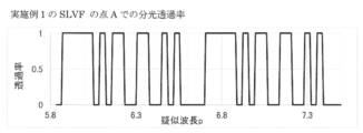
- FIG. 3 is a diagram showing the spectral transmittance of the filter of FIG. 2, where the horizontal axis represents the pseudo wavelength p and the vertical axis represents the transmittance.
- FIG. 3 is a diagram similarly showing the spectral transmittance of the filter of FIG. 2, in which the horizontal axis represents wavelength p and the vertical axis represents transmittance.
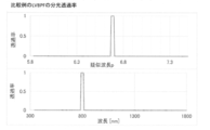
- FIG. 3 is a diagram showing spectral transmittances at a point A and a point B that is away from the point A in the y direction by a distance ⁇ y in the filter of FIG. 2. It is a figure which shows the relationship between the wavelength ⁇ and the pseudo wavelength p in the filter of FIG. It is a figure which shows the relationship between the position y in the filter of FIG. 2 and the thickness of an interference film. It is a figure which shows the result of having simulated the spectrum restoration by the measurement and calculation in a certain pixel of a two-dimensional sensor. The spectral transmittance of a linear variable bandpass filter (LVBPF) in a comparative example is shown.
- LLBPF linear variable bandpass filter
- the upper diagram shows the relationship between the pseudo wavelength p and the transmittance
- the lower diagram shows the relationship between the wavelength ⁇ and the transmittance.
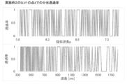
- the spectral transmittance of the filter in Example 2 is shown.
- the upper figure shows the relationship between the pseudo wavelength p and the transmittance
- the lower figure shows the relationship between the wavelength ⁇ and the transmittance.
- FIG. 8 is a diagram showing a result of simulating spectrum restoration by measurement and calculation in a pixel of a two-dimensional sensor in Example 2.
- the spectral transmittance of the filter in Example 2 is shown.
- the upper figure shows the relationship between the pseudo wavelength p and the transmittance
- the lower figure shows the relationship between the wavelength ⁇ and the transmittance.
- FIG. 8 is a diagram showing a result of simulating spectrum restoration by measurement and calculation at a pixel of a two-dimensional sensor in Example 3.
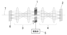
- FIG. 1 is a diagram showing a configuration of a spectroscopic device according to an embodiment of the present invention.
- the spectroscopic device uses a filter 1, a two-dimensional sensor 2, an objective optical system 3 for forming an image of a measurement target surface of the measurement target 6 on the filter 1, and light transmitted through the filter.
- It includes a relay optical system 4 that forms an image on a two-dimensional sensor and a drive unit 5.
- the objective optical system 3 forms an image of the surface to be measured on the surface of the filter 1, and the light transmitted through the filter 1 is transmitted.
- the relay optical system 4 forms an image on the two-dimensional sensor 2.
- the objective optical system 3 and the relay optical system 4 each have a known configuration having a plurality of lenses.
- the drive unit 5 drives and scans the filter 1 in the direction perpendicular to the optical axis 7 (the direction of the upward arrow in FIG. 1), and the two-dimensional sensor 2 detects the intensity of light from the measurement target.
- It is a vessel and is composed of an image sensor.
- the filter 1 is a filter (SLVF) which has a spectral transmittance different depending on the position in the direction perpendicular to the optical axis 7 and has a characteristic of transmitting light in a plurality of wavelength bands.
- the filter may be referred to as SLVF.
- the spectral transmittance is the transmittance for each wavelength of light.
- the wavelength range to be measured has a characteristic that two or more wavelength bands having a transmittance of 80% or more exist and three or more wavelength bands having a transmittance of 20% or less exist. .. With the filter 1 having such a configuration, the light utilization efficiency is high, and the measurement at a high S / N ratio can be stably performed.
- the calculation of the spectral information using the data obtained by the two-dimensional sensor 2 may be performed by the spectroscopic device itself, or the data obtained by the two-dimensional sensor 2 may be used in an external arithmetic unit such as a personal computer. It may be transmitted and performed by this external arithmetic unit.
- each element is a pseudo wavelength obtained by logarithmically converting the wavelength, and is sampled at equal intervals.
- the diagonal matrix includes the efficiency and transmittance of the optical system other than the filter 1, and the spectral sensitivity of the two-dimensional sensor 2.
- This measurement optical system has no sensitivity other than the wavelength range to be measured.
- the measured value vector M is a series of data sequentially measured while scanning (moving) the filter 1.
- the spectral transmittance of the filter 1 in each measurement be a row vector, and the matrix in which they are arranged is
- the j-th row represents the spectral transmittance of the filter 1 in the j-th measurement.
- FIG. 2 shows an example of the filter 1 in a schematic diagram.
- 6A is a front view seen from the light irradiation direction
- FIG. 6B is a sectional view taken along line bb of FIG.
- the spectral transmittance of the filter 1 shown in FIG. 2 will be described.
- the spectral transmittance at a certain point A is set as shown in FIGS. 3 and 4.
- FIG. 3 shows the pseudo wavelength p on the horizontal axis and the transmittance on the vertical axis
- FIG. 4 shows the wavelength p on the horizontal axis and the transmittance on the vertical axis, and the wavelength range to be measured.
- the pseudo wavelength p will be described later.
- the spectral transmittance of the filter 1 at the point B separated from a certain point A in the y direction by ⁇ y is a graph of the spectral transmittance with the horizontal axis as the pseudo wavelength p, as shown in FIG.
- the spectral transmittance at point A is shifted to the short wavelength side by a predetermined amount.
- the filter 1 having such characteristics is composed of an interference film filter in which dielectric multilayer films (also referred to as interference films) 12 and 12 are formed on both sides of the glass substrate 11 in the optical axis direction. it can.
- the thickness of each of the multilayer films 12 and 12 changes continuously depending on the position, and the transmittance spectrum is shifted.
- the matrix S of the transmittance of the filter 1 when scanning the filter 1 in the y direction where the spectral transmittance changes by the driving unit 5 by the distance ⁇ y and measuring 23 times is
- the j-th row is the spectral transmittance of the filter 1 in the j-th measurement
- the k-th column is the spectral transmittance at the pseudo wavelength p k
- p k p 1 + (k-1) ⁇ p
- k 1, 2, 3, ..., n
- the pseudo wavelength p is evenly spaced.
- This matrix S is the same matrix as the Hadamard transform spectrum, and the S/N ratio of the spectroscopic measurement value obtained by the calculation by the inverse matrix is a linear variable bandpass filter (LVBPF) that transmits only one wavelength band as a filter.
- LLBPF linear variable bandpass filter
- a detailed explanation is described in, for example, Hadamard transform spectroscopy, Tatsuo Arikawa (Journal of the Physical Society of Japan, Vol. 39, No. 11, p835 (1984)).
- the filter 1 When using the filter 1 having such characteristics, the filter 1 is moved so that the converted pseudo-wavelength p changes at an equal pitch, and the measurement and the inverse matrix calculation are performed sequentially on the pseudo-wavelength p-axis. Equal pitch spectral information can be obtained. By converting it to the wavelength ⁇ , spectral information with the wavelength ⁇ on the horizontal axis can be easily obtained. However, in that case, the data does not have the same pitch on the wavelength ⁇ axis.
- the pitch on the wavelength ⁇ axis is proportional to the wavelength ⁇ .
- the layer number is i
- the position in the direction y in which the spectral transmittance changes is y k
- y k y 1 + (k-1) * ⁇ y
- k 1, 2, 3, ..., n
- the thickness of the layer at that position is hi (y k )
- the shift amount of the pseudo wavelength p is linear with respect to the position y, and if the position y is shifted at equal intervals, the pseudo wavelength p also shifts at the same pitch.
- FIG. 6 shows the relationship between the wavelength ⁇ and the pseudo wavelength p in this embodiment
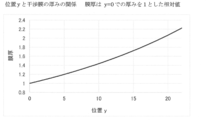
- FIG. 7 shows the relationship between the position y in the filter 1 and the thickness of the interference film.
- the filter 1 is shifted by 1 mm and measured 23 times, the measurement value vector M is acquired, and the spectrum is calculated by the above calculation.
- the measured values of all the pixels can be measured by sequentially shifting the filter 1 by 0.1 mm in the y direction. You can get a vector.
- the eleventh line of the two-dimensional sensor 2 can perform the k-1th measurement at the same time, so that the measurement can be performed efficiently. is there.
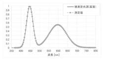
- FIG. 8 shows a result of simulating spectrum restoration by measurement and calculation at a certain pixel of the two-dimensional sensor 2 in this example.
- the solid line is the actual measurement value (true value) of the light source to be measured, and the broken line is the value calculated.
- the actual measurement result and the calculation result are in good agreement, and it can be seen that they are restored correctly.
- the transmittance matrix S in the filter according to the comparative example is a 23 ⁇ 23 diagonal matrix.
- the basic configuration of the second embodiment is the same as that of the first embodiment, but the characteristics of the filter 1 are different, and the number of rows and the number of columns of the transmittance matrix S of the filter 1 are also different.
- the spectral transmittance of the filter 1 in Example 2 is shown in FIG.
- the upper diagram shows the relationship between the pseudo wavelength p and the transmittance
- the lower diagram shows the relationship between the wavelength ⁇ and the transmittance.
- FIG. 11 shows a result of simulating the spectrum restoration by the measurement and the calculation at a certain pixel of the two-dimensional sensor 2 in the second embodiment.
- the solid line is the actual measured value (true value) of the light source to be measured
- the broken line is the value calculated. In this case as well, it can be seen that the actual measurement result and the calculation result are in good agreement, and that they are correctly restored.
- the transmittance matrix S of the linear variable bandpass filter (LVBPF) according to the comparison is a 103 ⁇ 103 diagonal matrix.
- Example 2 the wavelength resolution is improved as compared with Example 1. In addition, the effect of improving the S / N ratio is also high.
- Example 3 The basic configuration of the third embodiment is the same as that of the first embodiment, but the characteristics of the filter 1 are different, and the number of rows and the number of columns of the transmittance matrix S of the filter 1 are also different.
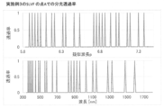
- the spectral transmittance of the filter 1 in Example 3 is shown in FIG.
- the upper diagram shows the relationship between the pseudo wavelength p and the transmittance
- the lower diagram shows the relationship between the wavelength ⁇ and the transmittance.
- FIG. 13 shows a result of simulating spectrum restoration by measurement and calculation at a certain pixel of the two-dimensional sensor 2 in Example 3.
- the solid line is the actual measurement value (true value) of the light source to be measured
- the broken line is the value calculated. In this case as well, it can be seen that the actual measurement result and the calculation result are in good agreement and are correctly restored.
- the transmittance matrix S of the linear variable bandpass filter (LVBPF) according to the comparison is a 111 ⁇ 111 diagonal matrix.
- Example 3 the wavelength resolution is as high as or higher than that in Example 2.
- the effect of improving the S / N ratio is lower than that of Example 2.
- the filter 1 of Example 2 has a complicated spectral transmittance waveform and is difficult to manufacture, but the filter 1 of Example 3 has a relatively simple spectral transmittance waveform and is difficult to manufacture. Is preferable in that it is low.
- the filter 1 has a characteristic that the spectral transmittance differs depending on the position and transmits light in a plurality of wavelength bands. Therefore, by scanning this filter, one wavelength is obtained. Compared with the case of using a linear variable band pass filter (LVBPF) that transmits only band light, the light utilization efficiency is high, and a spectroscopic device capable of measuring at a high S / N ratio can be obtained.
- LLBPF linear variable band pass filter
- the wavelength dispersion of the refractive index of the glass substrate 11 and the dielectric multilayer film 12 is ignored, but in reality, the calculation deviates slightly due to the influence of the wavelength dispersion of the refractive index.
- the thickness of the film with respect to the film design and the position y may be corrected so that the error becomes small.
- the transmittance waveform with respect to the pseudo wavelength is shifted by a constant amount, but the movement amount of the filter 1 does not have to be constant.
- the shift amount of the transmittance waveform may not be constant, or the transmittance waveform may be slightly distorted. In that case, the effect of improving the S/N ratio becomes small, but the spectral information can be measured.
- the filter 1 in the above embodiment is provided with the interference films 12 and 12 on both the front and back surfaces of the glass substrate 11 in the optical axis direction
- the interference film 12 may be provided on only one side, or a plurality of filters 1 may be provided. Therefore, the desired spectral transmittance may be realized.
- a short-wavelength cut filter or a long-wavelength cut filter that cuts light outside the measurement wavelength range may be installed in the optical system.
- the present invention can be used when calculating the spectral information of the light to be measured.
Landscapes
- Physics & Mathematics (AREA)
- Spectroscopy & Molecular Physics (AREA)
- General Physics & Mathematics (AREA)
- Spectrometry And Color Measurement (AREA)
Abstract
位置により分光透過率が異なるとともに、測定対象からの複数の波長帯の光を透過させる特性を有するフィルター(1)と、フィルターを走査する駆動手段(5)と、フィルターを透過した測定対象からの光の強度を検出する検出器2であって、駆動手段(5)によってフィルター(1)が走査されたときの光の強度を順次測定することにより、分光情報の算定に用いられる複数の測定データを取得する検出器(2)と、を備えている。
Description
この発明は、測定対象である光の分光情報を算定するのに用いられる分光装置及び分光測定用データの取得方法に関する。
従来、透過部位に応じて透過波長が異なる透過波長変化型フィルター(リニアバリアブルバンドパスフィルター(LVBPF))を走査させて分光情報を得る分光装置が知られている(例えば特許文献1、特許文献2)。
しかし、LVBPFを走査させる分光装置では、LVBPFの透過波長域以外の光は、測定に利用されないので、光利用効率が低く、測定のS/N比が低くなってしまうという課題がある。
特に2次元分光装置の場合、測定範囲を多数の小領域に分割し、各小領域の分光情報を測定するため、測定光量が小さく、さらに、LVBPFの光利用効率が低いので、測定のS/N比が低くなってしまうという課題がある。
この発明は、このような課題を解決するためになされたものであって、光利用効率が高く、高S/N比での測定が可能な分光装置及び分光測定用データの取得方法を提供することを目的とする。
上記目的は以下の手段によって達成される。
(1)位置により分光透過率が異なるとともに、測定対象からの複数の波長帯の光を透過させる特性を有するフィルターと、前記フィルターを走査する駆動手段と、前記フィルターを透過した測定対象からの光の強度を検出する検出器であって、前記駆動手段によって前記フィルターが走査されたときの光の強度を順次測定することにより、分光情報の算定に用いられる複数の測定データを取得する検出器と、を備えた分光装置。
(2)前記フィルターは、測定対象の波長域において、透過率80%以上の波長帯が2つ以上存在し、かつ、透過率20%以下の波長帯が3つ以上存在する前項1に記載の分光装置。
(3)前記検出器は2次元センサーであり、測定対象面の像を前記フィルター上に形成する対物光学系と、前記フィルターを透過した光を、前記2次元センサー上に結像するリレー光学系と、をさらに備えている前項1または2に記載の分光装置。
(4)位置により分光透過率が異なるとともに、測定対象からの複数の波長帯の光を透過させる特性を有するフィルターを用い、前記フィルターを走査しながら、フィルターを透過した測定対象からの光の強度を検出器で順次測定することにより、分光情報の算定に用いられる複数の測定データを取得する分光測定用データの取得方法。
(5)前記フィルターは、測定対象の波長域において、透過率80%以上の波長帯が2つ以上存在し、かつ、透過率20%以下の波長帯が3つ以上存在する前項4に記載の分光測定用データの取得方法。
(6)前記検出器は2次元センサーであり、測定対象面の像を対物光学系により前記フィルター上に形成し、前記フィルターを透過した光を、リレー光学系により前記2次元センサー上に結像する請求項4または5に記載の分光測定用データの取得方法。
(1)位置により分光透過率が異なるとともに、測定対象からの複数の波長帯の光を透過させる特性を有するフィルターと、前記フィルターを走査する駆動手段と、前記フィルターを透過した測定対象からの光の強度を検出する検出器であって、前記駆動手段によって前記フィルターが走査されたときの光の強度を順次測定することにより、分光情報の算定に用いられる複数の測定データを取得する検出器と、を備えた分光装置。
(2)前記フィルターは、測定対象の波長域において、透過率80%以上の波長帯が2つ以上存在し、かつ、透過率20%以下の波長帯が3つ以上存在する前項1に記載の分光装置。
(3)前記検出器は2次元センサーであり、測定対象面の像を前記フィルター上に形成する対物光学系と、前記フィルターを透過した光を、前記2次元センサー上に結像するリレー光学系と、をさらに備えている前項1または2に記載の分光装置。
(4)位置により分光透過率が異なるとともに、測定対象からの複数の波長帯の光を透過させる特性を有するフィルターを用い、前記フィルターを走査しながら、フィルターを透過した測定対象からの光の強度を検出器で順次測定することにより、分光情報の算定に用いられる複数の測定データを取得する分光測定用データの取得方法。
(5)前記フィルターは、測定対象の波長域において、透過率80%以上の波長帯が2つ以上存在し、かつ、透過率20%以下の波長帯が3つ以上存在する前項4に記載の分光測定用データの取得方法。
(6)前記検出器は2次元センサーであり、測定対象面の像を対物光学系により前記フィルター上に形成し、前記フィルターを透過した光を、リレー光学系により前記2次元センサー上に結像する請求項4または5に記載の分光測定用データの取得方法。
前項(1)に記載の発明によれば、フィルターは、位置により分光透過率が異なるとともに、複数の波長帯の光を透過させる特性を有しているから、このフィルターを走査することで、1個の波長帯の光のみを透過させるリニアバリアブルバンドパスフィルター(LVBPF))を用いる場合に較べて光利用効率が高く、高S/N比での測定が可能な分光装置とすることができる。
前項(2)に記載の発明によれば、フィルターは、測定対象の波長域において、透過率80%以上の波長帯が2つ以上存在し、かつ、透過率20%以下の波長帯が3つ以上存在するから、光利用効率が高く、高S/N比での測定を安定的に行うことができる。
前項(3)に記載の発明によれば、高S/N比で2次元分光情報の測定が可能な分光装置とすることができる。
前項(4)に記載の発明によれば、光利用効率が高く高S/N比の測定用データを得ることができる。
前項(5)に記載の発明によれば、利用効率が高く高S/N比の測定用データを安定的に得ることができる。
前項(6)に記載の発明によれば、高S/N比で2次元分光情報の測定が可能な測定用データを得ることができる。
以下、この発明の実施形態を図面に基づいて説明する。
図1は、本発明の一実施形態に係る分光装置の構成を示す図である。図1に示すように、分光装置は、フィルター1と、2次元センサー2と、測定対象物6における測定対象面の像をフィルター1上に形成する対物光学系3と、フィルターを透過した光を2次元センサー上に結像するリレー光学系4と、駆動部5を備えており、対物光学系3により、測定対象面の像をフィルター1の面上に形成し、フィルター1を透過した光を、リレー光学系4により2次元センサー2上に結像させるようになっている。なお、対物光学系3及びリレー光学系4は、それぞれ複数のレンズを有する公知の構成である。
駆動部5は、フィルター1を光軸7と垂直な方向(図1中の上向き矢印の方向)へ駆動走査するものであり、2次元センサー2は、測定対象からの光の強度を検出する検出器であり、撮像素子によって構成されている。
フィルター1は、光軸7と垂直な方向における位置により分光透過率が異なるとともに、複数の波長帯の光を透過させる特性を有するフィルター(SLVF)である。以下の説明では、フィルターをSLVFと記すこともある。分光透過率とは光の波長毎の透過率である。好ましくは、測定対象の波長域において、透過率80%以上の波長帯が2つ以上存在し、かつ、透過率20%以下の波長帯が3つ以上存在する特性を有しているのが良い。このような構成のフィルター1によって、光利用効率が高く、高S/N比での測定を安定的に行うことができる。
上記の特性を有するフィルター1を駆動部5により光軸7と垂直な方向へ駆動走査しながら、順次、2次元センサー2で撮像すると、毎回、異なる波長域の光による像(2次元情報)が得られる。それらのデータから、演算により各点の分光情報が算出される。駆動部5によるフィルター1の具体的な駆動機構も公知であり、前述した特許文献1及び2に記載の駆動機構や、その他一般的な駆動方法を使うことが可能である。
なお、2次元センサー2で得られたデータを用いての分光情報の算定は、分光装置自身で行われても良いし、2次元センサー2で得られたデータをパーソナルコンピュータ等の外部演算装置に送信し、この外部演算装置で行われても良い。
次に、2次元センサー2のある画素の測定データについて考える。その画素には、測定対象面の対応する領域からの光が集光され、測定される。その測定対象の分光放射輝度Vを、

とする。各要素は、後で説明するように、波長を対数変換した擬似波長で、等間隔にサンプリングされている。
フィルター1を除く測定系の分光感度を対角成分とする対角行列を、
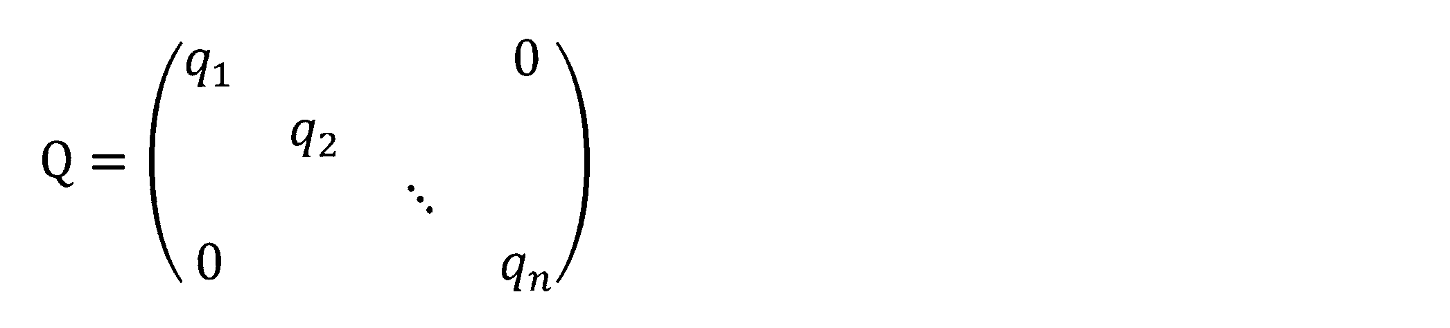
とする。対角行列で、フィルター1以外の光学系の効率、透過率、2次元センサー2の分光感度を含む。この測定光学系は、測定対象の波長域以外には感度が無い。
フィルター1を走査(移動)させながら順次測定した一連のデータを、測定値ベクトルM
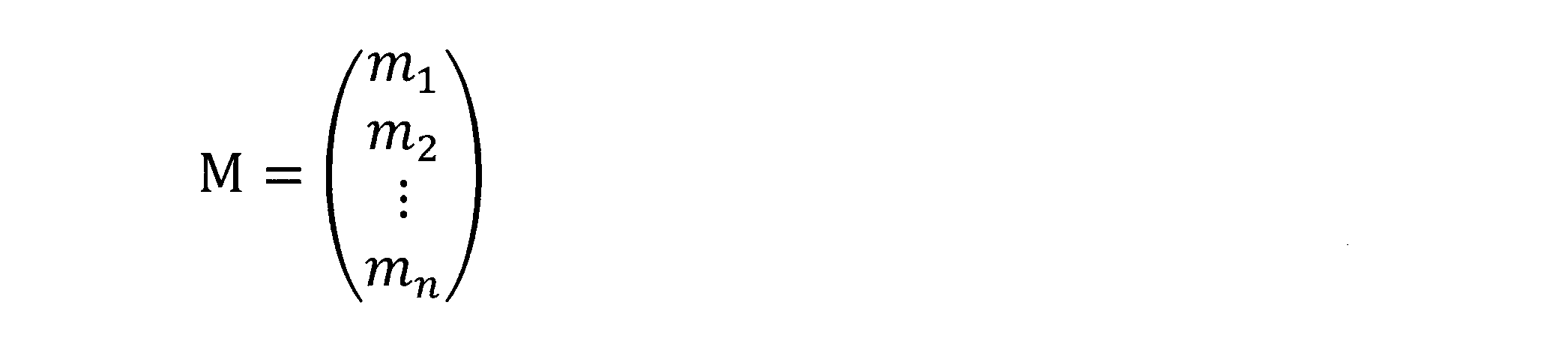
とし、各測定におけるフィルター1の分光透過率を行ベクトルとし、それを並べた行列を、

とする。上記行列Sにおいて、第j行目は、j回目の測定におけるフィルター1の分光透過率を表している。
V、Q、M、S はM=S*Q*Vの関係にあり、フィルター1を駆動部5により所定量ずつ移動させながら、n回測定することで、測定値の列ベクトルMが測定される。
よって、V=Q-1*S-1*Mの演算により、分光放射輝度Vを得ることができる。S、Qは事前に測定等によりデータを取得可能であり、その逆行列S-1、Q-1も事前に算出可能である。
[実施例1]
図2にフィルター1の一例を模式図で示す。同図(a)は光の照射方向から見た正面図、(b)は(a)のb-b線断面図である。
[実施例1]
図2にフィルター1の一例を模式図で示す。同図(a)は光の照射方向から見た正面図、(b)は(a)のb-b線断面図である。
図2に示したフィルター1の分光透過率について説明する。図2(a)の正面図において、フィルター1の走査方向と平行な方向(図2(a)の上下方向)をy方向とし、走査方向と直交する方向をx方向とすると、図2のフィルター1は、y方向には位置により分光透過率が変化し、x方向には、分光透過率は変化しない。
図2に示すフィルターでは、ある点Aにおける分光透過率が図3及び図4に示すように設定されている。図3は横軸に疑似波長pを、縦軸に透過率を示したものであり、図4は横軸に波長pを、縦軸に透過率を示したものであり、測定対象の波長域において、透過率80%以上の波長帯が2つ以上存在し、かつ、透過率20%以下の波長帯が3つ以上存在する。なお、擬似波長pについては後述する。
図2に示すように、ある点Aからy方向に距離Δy離れた点Bでのフィルター1の分光透過率は、図5に示すように、横軸を擬似波長pとした分光透過率のグラフにおいて、点Aでの分光透過率が所定の量だけ、短波長側へシフトしたものとなっている。このような特性のフィルター1は、たとえば図2に示すように、ガラス基板11の光軸方向の両面に誘電体の多層膜(干渉膜ともいう)12、12を成膜した干渉膜フィルターで構成できる。模式図に示したように、多層膜12、12の厚みが、位置により連続的に変化することで、透過率スペクトルがシフトする特性となる。
駆動部5により、距離Δyずつ、フィルター1を分光透過率が変化するy方向へ走査して、23回測定した場合のフィルター1の透過率の行列Sは、
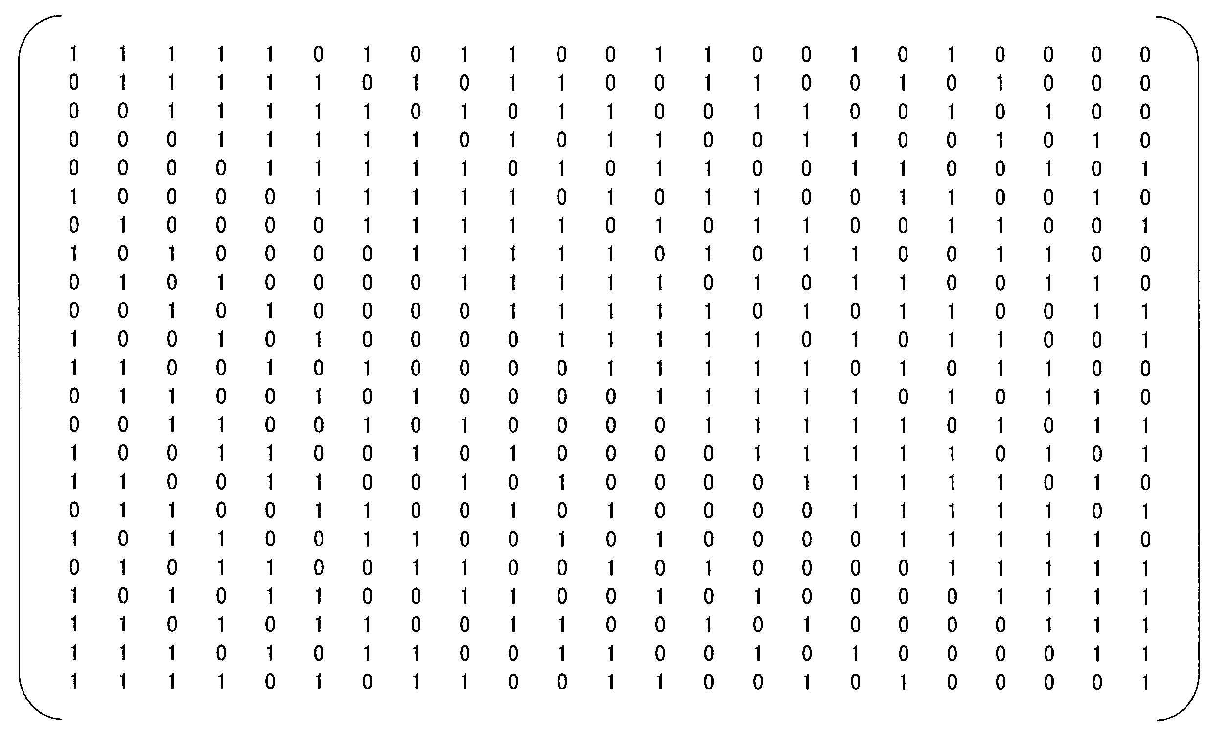
と表せる。上記行列Sにおいてj行目は、j回目の測定におけるフィルター1の分光透過率、k列は擬似波長pk での分光透過率で、
pk =p1+(k-1)Δp ただしk=1,2,3,・・・,n
擬似波長pで等間隔になっている。
pk =p1+(k-1)Δp ただしk=1,2,3,・・・,n
擬似波長pで等間隔になっている。
この実施例では、
p1=5.886,対応波長360.0nm
p2=5.922,対応波長373.3nm
p3=5.959,対応波長387.1nm
・・・
p23=6.685,対応波長800.0nm
である。
p1=5.886,対応波長360.0nm
p2=5.922,対応波長373.3nm
p3=5.959,対応波長387.1nm
・・・
p23=6.685,対応波長800.0nm
である。
この行列Sは、アダマール変換分光と同じ行列となっており、逆行列による演算で求めた分光測定値のS/N比は、フィルターとして1つの波長域のみ透過させるリニアバリアブルバンドパスフィルタ(LVBPF)を用いた場合(透過率行列Sが対角行列となる)に比べ、

倍、改善される。上式において、nは行列の行数、列数であり、実施例1ではn=23である。詳しい説明は、たとえば、アダマール変換分光、蟻川 達男(日本物理学会誌 第39巻 第11号p835(1984))に記載されている。
次に、擬似波長pについて説明する。
フィルター1が、図2に示したような、ガラス基板11に誘電体の多層膜12、12を成膜した干渉膜フィルターの場合、多層膜12、12の各厚みを単純に元のk倍の厚みにしても、透過率スペクトルは単純な波長シフトとならない。ガラス基板11、誘電体多層膜12、12の屈折率の波長分散は無視できるとすると、ある干渉膜12の波長λでの透過率をT1(λ)、その干渉膜12の各層の厚みをk倍した干渉膜12の透過率をTk(λ)とすると、T1(λ1)=Tk(kλ1)となり、単純な波長シフトとならない。
以下のような波長λから擬似波長pへの変換を考える。
λ=exp(p)
p=log(λ)
擬似波長pでの基準の干渉膜12の透過率の関数をU1とすると、
T1(λ1)=U1(p1)
干渉膜12の各層の厚みがk倍の透過率の関数をUkとすると、
Tk(λk)=Uk (pk)
となる。ここで、
T1(λ1)=U1(p1)=Tk(λk)=Uk (pk)
とする。T1(λ1)=Tk(kλ1)であるから、
λk=kλ1
である。ここで、λ1=exp(p1)、λk=exp(pk)なので、
λk=kλ1=exp(pk)=k*exp(p1)=exp(log(k)+p1)
よって、pk=log(k)+p1であり、
U1(p1)=Uk(pk)=Uk(log(k)+p1)
となる。
λ=exp(p)
p=log(λ)
擬似波長pでの基準の干渉膜12の透過率の関数をU1とすると、
T1(λ1)=U1(p1)
干渉膜12の各層の厚みがk倍の透過率の関数をUkとすると、
Tk(λk)=Uk (pk)
となる。ここで、
T1(λ1)=U1(p1)=Tk(λk)=Uk (pk)
とする。T1(λ1)=Tk(kλ1)であるから、
λk=kλ1
である。ここで、λ1=exp(p1)、λk=exp(pk)なので、
λk=kλ1=exp(pk)=k*exp(p1)=exp(log(k)+p1)
よって、pk=log(k)+p1であり、
U1(p1)=Uk(pk)=Uk(log(k)+p1)
となる。
つまり、干渉膜12の各層の厚みをk倍すると、波長λを疑似波長pに座標変換した軸において、透過率がlog(k)だけシフトする。
このような特性のフィルター1を用いる場合には、変換された疑似波長pが等ピッチで変化するようにフィルター1を移動させて、順次測定、逆行列演算をすれば、疑似波長p軸上で等ピッチの分光情報が得られる。それを、波長λに変換すれば、容易に横軸が波長λの分光情報が得られる。ただし、その場合、波長λ軸上では等ピッチのデータとはならない。

であるから、波長λ軸上でのピッチは波長λに比例する。
干渉膜12の各層の厚みは、層の番号をiとし、分光透過率が変化する方向yの位置を yk、
yk=y1+(k-1)*Δy ただしk=1,2,3,・・・,n
とし、その位置での層の厚みをhi(yk)とすると、
yk=y1+(k-1)*Δy ただしk=1,2,3,・・・,n
とし、その位置での層の厚みをhi(yk)とすると、

となるように構成する。このように構成することで、位置がΔyずれるごとに、厚みがg倍されていく。
前述したように、干渉膜12の各層の厚みがk倍されると、分光透過率は、疑似波長p軸上で、log(k)だけシフトするので、位置y1を基準としたとき、位置ykにおける分光透過率の、擬似波長p軸上でのシフト量はlog(k)*(k-1)であり、そのシフト量だけずれる。つまり、前述の擬似波長のピッチは、Δp=log(g)であり、
pk=p1+(k-1)*log(g)
である。
pk=p1+(k-1)*log(g)
である。
位置yに対し擬似波長pのシフト量は線形であり、位置yを等間隔でずらすと、擬似波長pも等ピッチでずれていく。本実施例での波長λと疑似波長pとの関係を図6に、フィルター1における位置yと干渉膜の厚みの関係を図7に示す。本実施例では、y方向に22mmずらすと厚みが2.222倍となり、擬似波長pが0.7985シフトする。例えば、p=6.6846(λ=800nm)が、p=5.8861(λ=360nm)にシフトする。
2次元センサー2のある画素を考えると、フィルター1を1mmずつずらして23回測定し、測定値ベクトルMを取得し、上述の演算によりスペクトルを算出する。
リレー光学系4の倍率を-1、2次元センサー2のy方向の画素ピッチを0.1mmとすると、フィルター1をy方向に0.1mmずつずらしながら順次測定すれば、すべての画素の測定値ベクトルを取得できる。この時、たとえば、2次元センサー2の第1行目がk回目の測定をする際、同時に、2次元センサー2の第11行目はk-1回目の測定を行え、効率よく測定が可能である。
本実施例において、2次元センサー2のある画素での測定と演算でのスペクトル復元を、シミュレーションした結果を図8に示す。図8において、実線は被測定光源での実際の測定値(真値)であり、破線は演算による値である。図8から理解されるように、実際の測定結果と演算結果とが良く一致しており、正しく復元されていることが分かる。
一般的な1つの波長域のみ透過させるリニアバリアブルバンドパスフィルタ(LVBPF)を用いて、同等の波長分解能とするシステム(比較例)と比べた場合に、S/N比がどれだけ改善しているかを、測定ごとにランダムなノイズが発生すると仮定して算出すると、2.502倍の改善であった。これは、上記[数6]に示したS/N理論式において、n=23とした場合に一致している。比較例におけるリニアバリアブルバンドパスフィルタ(LVBPF)の分光透過率を図9に示す。同図上側の図は疑似波長pと透過率の関係を、下側の図は波長λと透過率の関係をそれぞれ示している。比較例に係るフィルタにおける透過率行列Sは23×23の対角行列になる。
[実施例2]
実施例2の基本構成は実施例1と同じであるが、フィルター1の特性が異なり、フィルター1の透過率行列Sの行数、列数も異なる。実施例2でのフィルター1の分光透過率を図10に示す。上側の図は疑似波長pと透過率の関係を、下側の図は波長λと透過率の関係をそれぞれ示している。
[実施例2]
実施例2の基本構成は実施例1と同じであるが、フィルター1の特性が異なり、フィルター1の透過率行列Sの行数、列数も異なる。実施例2でのフィルター1の分光透過率を図10に示す。上側の図は疑似波長pと透過率の関係を、下側の図は波長λと透過率の関係をそれぞれ示している。
実施例2では、n=103の場合のアダマール変換分光の行列に一致する分光透過率となっている。
実施例2において、2次元センサー2のある画素での測定と演算でのスペクトル復元を、シミュレーションした結果を図11に示す。図11において、実線は被測定光源での実際の測定値(真値)であり、破線は演算による値である。この場合も、実際の測定結果と演算結果とが良く一致しており、正しく復元されていることが分かる。
同等の波長分解能のリニアバリアブルバンドパスフィルタ(LVBPF)を基準とした場合のS/N比改善効果は5.124倍であり、上記[数6]に示したS/N理論式において、n=103とした場合に一致する。なお、比較に係るリニアバリアブルバンドパスフィルタ(LVBPF)の透過率行列Sは103×103の対角行列である。
実施例2では、実施例1に比べ波長分解能が改善している。また、S/N比の改善効果も高い。
[実施例3]
実施例3の基本構成は実施例1と同じであるが、フィルター1の特性が異なり、フィルター1の透過率行列Sの行数、列数も異なる。実施例3でのフィルター1の分光透過率を図12に示す。上側の図は疑似波長pと透過率の関係を、下側の図は波長λと透過率の関係をそれぞれ示している。
[実施例3]
実施例3の基本構成は実施例1と同じであるが、フィルター1の特性が異なり、フィルター1の透過率行列Sの行数、列数も異なる。実施例3でのフィルター1の分光透過率を図12に示す。上側の図は疑似波長pと透過率の関係を、下側の図は波長λと透過率の関係をそれぞれ示している。
実施例3におけるフィルター1の透過率行列Sは、実施例1での23×23の行列Sの各行、各列の間に、要素がすべて0の行及び列を4行及び4列ずつ挿入した、111×111の行列(23+22*4=111)になる。
実施例3において、2次元センサー2のある画素での測定と演算でのスペクトル復元を、シミュレーションした結果を図13に示す。図13において、実線は被測定光源での実際の測定値(真値)であり、破線は演算による値である。この場合も、実際の測定結果と演算結果とが良く一致しており、正しく復元されていることが分かる。
同等の波長分解能のリニアバリアブルバンドパスフィルタ(LVBPF)を基準とした場合のS/N比改善効果は2.502倍であり、実施例1と同じく上記[数6]に示したS/N理論式において、n=23とした場合に一致する。なお、比較に係るリニアバリアブルバンドパスフィルタ(LVBPF)の透過率行列Sは111×111対角行列である。
実施例3では、実施例2と同程度以上の高い波長分解能となっている。一方で、S/N比の改善効果は実施例2に比べると低くなっている。しかし、実施例2のフィルター1は複雑な分光透過率波形となっており、製作難易度が高いが、実施例3のフィルター1では比較的シンプルな分光透過率波形となっており、製作難易度が低い点で好ましい。
このようにこの実施形態では、フィルター1は、位置により分光透過率が異なるとともに、複数の波長帯の光を透過させる特性を有しているから、このフィルターを走査することで、1個の波長帯の光のみを透過させるリニアバリアブルバンドパスフィルター(LVBPF))を用いる場合に較べて光利用効率が高く、高S/N比での測定が可能な分光装置とすることができる。
以上の実施形態では、ガラス基板11、誘電体多層膜12の屈折率の波長分散を無視したが、実際には、屈折率の波長分散の影響により、上記計算から若干ずれる。その誤差が小さくなるように、膜設計、位置yに対する膜の厚みを補正しても良い。
また、上記実施形態では、フィルター1を一定量ずつy方向にシフトさせると、擬似波長に対する透過率波形が一定量ずつシフトする構成としたが、フィルター1の移動量が一定でなくても良いし、透過率波形のシフト量が一定でなくても良いし、透過率波形が多少くずれても良い。その場合、S/N比の改善効果は小さくなってしまうが、分光情報の測定は可能である。
また、上記実施形態におけるフィルター1は、ガラス基板11の光軸方向の表裏両面に干渉膜12、12を設けているが、片面のみに干渉膜12を設ける構成でも良いし、複数枚のフィルター1で、所望の分光透過率を実現しても良い。
また、測定波長域外の光をカットする、短波長カットフィルター、長波長カットフィルターを、光学系に設置しても良い。
本発明は、測定対象である光の分光情報を算定する際に利用可能である。
1 フィルター
11 ガラス基板
12 多層膜(干渉膜)
2 2次元センサー
3 対物光学系
4 リレー光学系
5 駆動部
6 測定対象物
11 ガラス基板
12 多層膜(干渉膜)
2 2次元センサー
3 対物光学系
4 リレー光学系
5 駆動部
6 測定対象物
Claims (6)
- 位置により分光透過率が異なるとともに、測定対象からの複数の波長帯の光を透過させる特性を有するフィルターと、
前記フィルターを走査する駆動手段と、
前記フィルターを透過した測定対象からの光の強度を検出する検出器であって、前記駆動手段によって前記フィルターが走査されたときの光の強度を順次測定することにより、分光情報の算定に用いられる複数の測定データを取得する検出器と、
を備えた分光装置。 - 前記フィルターは、測定対象の波長域において、透過率80%以上の波長帯が2つ以上存在し、かつ、透過率20%以下の波長帯が3つ以上存在する請求項1に記載の分光装置。
- 前記検出器は2次元センサーであり、
測定対象面の像を前記フィルター上に形成する対物光学系と、
前記フィルターを透過した光を、前記2次元センサー上に結像するリレー光学系と、
をさらに備えている請求項1または2に記載の分光装置。 - 位置により分光透過率が異なるとともに、測定対象からの複数の波長帯の光を透過させる特性を有するフィルターを用い、
前記フィルターを走査しながら、フィルターを透過した測定対象からの光の強度を検出器で順次測定することにより、分光情報の算定に用いられる複数の測定データを取得する分光測定用データの取得方法。 - 前記フィルターは、測定対象の波長域において、透過率80%以上の波長帯が2つ以上存在し、かつ、透過率20%以下の波長帯が3つ以上存在する請求項4に記載の分光測定用データの取得方法。
- 前記検出器は2次元センサーであり、
測定対象面の像を対物光学系により前記フィルター上に形成し、
前記フィルターを透過した光を、リレー光学系により前記2次元センサー上に結像する請求項4または5に記載の分光測定用データの取得方法。
Priority Applications (2)
| Application Number | Priority Date | Filing Date | Title |
|---|---|---|---|
| JP2021504025A JPWO2020179628A1 (ja) | 2019-03-04 | 2020-02-27 | |
| US17/435,945 US11885680B2 (en) | 2019-03-04 | 2020-02-27 | Spectral device |
Applications Claiming Priority (2)
| Application Number | Priority Date | Filing Date | Title |
|---|---|---|---|
| JP2019-038587 | 2019-03-04 | ||
| JP2019038587 | 2019-03-04 |
Publications (1)
| Publication Number | Publication Date |
|---|---|
| WO2020179628A1 true WO2020179628A1 (ja) | 2020-09-10 |
Family
ID=72338647
Family Applications (1)
| Application Number | Title | Priority Date | Filing Date |
|---|---|---|---|
| PCT/JP2020/008078 Ceased WO2020179628A1 (ja) | 2019-03-04 | 2020-02-27 | 分光装置 |
Country Status (3)
| Country | Link |
|---|---|
| US (1) | US11885680B2 (ja) |
| JP (1) | JPWO2020179628A1 (ja) |
| WO (1) | WO2020179628A1 (ja) |
Cited By (1)
| Publication number | Priority date | Publication date | Assignee | Title |
|---|---|---|---|---|
| WO2025216121A1 (ja) * | 2024-04-11 | 2025-10-16 | コニカミノルタ株式会社 | 測定光学系及び測光装置 |
Families Citing this family (1)
| Publication number | Priority date | Publication date | Assignee | Title |
|---|---|---|---|---|
| WO2023283742A1 (en) | 2021-07-14 | 2023-01-19 | Westboro Photonics Inc. | Imager and spot sampler with translatable stage |
Citations (8)
| Publication number | Priority date | Publication date | Assignee | Title |
|---|---|---|---|---|
| JPH08128899A (ja) * | 1994-10-31 | 1996-05-21 | Satoshi Kawada | 分光画像収集装置 |
| JP2003214951A (ja) * | 2002-01-28 | 2003-07-30 | Matsushita Electric Works Ltd | 分光計測装置及び分光計測方法 |
| JP2006177812A (ja) * | 2004-12-22 | 2006-07-06 | Konica Minolta Sensing Inc | 二次元分光輝度計 |
| JP2014513315A (ja) * | 2011-03-03 | 2014-05-29 | エンクロマ, インコーポレイテッド | 多帯域色視フィルタおよびlp最適化による方法 |
| WO2016111308A1 (ja) * | 2015-01-07 | 2016-07-14 | 平本 政夫 | マルチスペクトル撮像装置 |
| JP2017207406A (ja) * | 2016-05-19 | 2017-11-24 | 株式会社トプコンテクノハウス | 測光装置 |
| US20180107015A1 (en) * | 2016-10-19 | 2018-04-19 | CSEM Centre Suisse d'Electronique et de Microtechnique SA - Recherche et Développement | Multispectral or Hyperspectral Imaging and Imaging System Based on Birefringent Subwavelength Resonating Structure |
| JP2018155962A (ja) * | 2017-03-17 | 2018-10-04 | 倉敷紡績株式会社 | 分光フィルタおよび分光測光装置 |
Family Cites Families (6)
| Publication number | Priority date | Publication date | Assignee | Title |
|---|---|---|---|---|
| US4856897A (en) * | 1987-08-14 | 1989-08-15 | D.O.M. Associates, Inc. | Raman spectrometer having Hadamard electrooptical mask and diode detector |
| US7636158B1 (en) * | 2004-09-24 | 2009-12-22 | Romuald Pawluczyk | Optimal coupling of high performance line imaging spectrometer to imaging system |
| JP5048795B2 (ja) * | 2010-01-21 | 2012-10-17 | 浜松ホトニクス株式会社 | 分光装置 |
| US10005256B2 (en) * | 2012-06-14 | 2018-06-26 | The Boeing Company | Selectively weakened stretched films |
| US10564334B2 (en) * | 2015-04-03 | 2020-02-18 | Konica Minolta, Inc. | Spectral filter and spectrometric device |
| US10943959B1 (en) * | 2018-02-14 | 2021-03-09 | Apple Inc. | Display device with a light modulating layer |
-
2020
- 2020-02-27 JP JP2021504025A patent/JPWO2020179628A1/ja active Pending
- 2020-02-27 US US17/435,945 patent/US11885680B2/en active Active
- 2020-02-27 WO PCT/JP2020/008078 patent/WO2020179628A1/ja not_active Ceased
Patent Citations (8)
| Publication number | Priority date | Publication date | Assignee | Title |
|---|---|---|---|---|
| JPH08128899A (ja) * | 1994-10-31 | 1996-05-21 | Satoshi Kawada | 分光画像収集装置 |
| JP2003214951A (ja) * | 2002-01-28 | 2003-07-30 | Matsushita Electric Works Ltd | 分光計測装置及び分光計測方法 |
| JP2006177812A (ja) * | 2004-12-22 | 2006-07-06 | Konica Minolta Sensing Inc | 二次元分光輝度計 |
| JP2014513315A (ja) * | 2011-03-03 | 2014-05-29 | エンクロマ, インコーポレイテッド | 多帯域色視フィルタおよびlp最適化による方法 |
| WO2016111308A1 (ja) * | 2015-01-07 | 2016-07-14 | 平本 政夫 | マルチスペクトル撮像装置 |
| JP2017207406A (ja) * | 2016-05-19 | 2017-11-24 | 株式会社トプコンテクノハウス | 測光装置 |
| US20180107015A1 (en) * | 2016-10-19 | 2018-04-19 | CSEM Centre Suisse d'Electronique et de Microtechnique SA - Recherche et Développement | Multispectral or Hyperspectral Imaging and Imaging System Based on Birefringent Subwavelength Resonating Structure |
| JP2018155962A (ja) * | 2017-03-17 | 2018-10-04 | 倉敷紡績株式会社 | 分光フィルタおよび分光測光装置 |
Non-Patent Citations (2)
| Title |
|---|
| CALUM WILLIAMS ET AL: "Single-step fabrication of thin-film linear variable bandpass filters based on metal-insulator-metal geometry", APPLIED OPTICS, vol. 55, no. 32, 9 November 2016 (2016-11-09), pages 9237 - 9241, XP055736697 * |
| DELTA OPTICAL: "Linear variable filter", DELTA OPTICAL THIN FILM CATALOG, 23 April 2016 (2016-04-23), pages 2 - 5, XP055736702, Retrieved from the Internet <URL:https://go.klv.co.jp/rs/467-JAD-820/images/KLV_630_Delta_filter_LVF.pdf> * |
Cited By (1)
| Publication number | Priority date | Publication date | Assignee | Title |
|---|---|---|---|---|
| WO2025216121A1 (ja) * | 2024-04-11 | 2025-10-16 | コニカミノルタ株式会社 | 測定光学系及び測光装置 |
Also Published As
| Publication number | Publication date |
|---|---|
| JPWO2020179628A1 (ja) | 2020-09-10 |
| US20220146309A1 (en) | 2022-05-12 |
| US11885680B2 (en) | 2024-01-30 |
Similar Documents
| Publication | Publication Date | Title |
|---|---|---|
| Monakhova et al. | Spectral DiffuserCam: lensless snapshot hyperspectral imaging with a spectral filter array | |
| US12174070B2 (en) | Fabry-perot fourier transform spectrometer | |
| Wang et al. | Dual-camera design for coded aperture snapshot spectral imaging | |
| JP2022002398A (ja) | 撮像装置および分光システム | |
| Descour et al. | Computed-tomography imaging spectrometer: experimental calibration and reconstruction results | |
| Zong et al. | Simple spectral stray light correction method for array spectroradiometers | |
| Wagadarikar et al. | Spectral image estimation for coded aperture snapshot spectral imagers | |
| US11885953B2 (en) | Apparatus and method of providing parameter estimation | |
| US20130027701A1 (en) | System and Method for Correcting Spectral Response Using a Radiometric Correction Filter | |
| TWI386617B (zh) | 反射式膜厚量測方法 | |
| Kim et al. | Aperture-encoded snapshot hyperspectral imaging with a lensless camera | |
| US20230393379A1 (en) | Apparatus and method of estimating values from images | |
| WO2020179628A1 (ja) | 分光装置 | |
| JP6744005B2 (ja) | 分光測定装置 | |
| Wang et al. | Miniaturized spectrometer based on MLP neural networks and a frosted glass encoder | |
| Fernandez et al. | Longwave infrared (LWIR) coded aperture dispersive spectrometer | |
| Shcheglov et al. | Miniaturized cost-effective broadband spectrometer employing a deconvolution reconstruction algorithm for resolution enhancement | |
| Xu et al. | Video‐Rate Spectral Imaging Based on Diffractive‐Refractive Hybrid Optics | |
| Dell'Endice et al. | Scene-based method for spatial misregistration detection in hyperspectral imagery | |
| Kutteruf et al. | Video rate nine-band multispectral short-wave infrared sensor | |
| CN105115908B (zh) | 金属锈斑最优光谱波段选取视觉检测装置和方法 | |
| US20220011090A1 (en) | Apparatus and methods for detecting light | |
| Baranski et al. | Computational integral field spectroscopy with diverse imaging | |
| Ohtera et al. | Direct estimation of NIR reflection spectra utilizing a snapshot-type spectrometer with photonic crystal multi-spectral filter arrays | |
| CN111272280B (zh) | 利用逆卷积提高光谱仪系统分辨率的方法 |
Legal Events
| Date | Code | Title | Description |
|---|---|---|---|
| 121 | Ep: the epo has been informed by wipo that ep was designated in this application |
Ref document number: 20766908 Country of ref document: EP Kind code of ref document: A1 |
|
| ENP | Entry into the national phase |
Ref document number: 2021504025 Country of ref document: JP Kind code of ref document: A |
|
| NENP | Non-entry into the national phase |
Ref country code: DE |
|
| 122 | Ep: pct application non-entry in european phase |
Ref document number: 20766908 Country of ref document: EP Kind code of ref document: A1 |