WO2020179600A1 - 排熱回収システム - Google Patents
排熱回収システム Download PDFInfo
- Publication number
- WO2020179600A1 WO2020179600A1 PCT/JP2020/007966 JP2020007966W WO2020179600A1 WO 2020179600 A1 WO2020179600 A1 WO 2020179600A1 JP 2020007966 W JP2020007966 W JP 2020007966W WO 2020179600 A1 WO2020179600 A1 WO 2020179600A1
- Authority
- WO
- WIPO (PCT)
- Prior art keywords
- dust
- amount
- exhaust
- exhaust heat
- exhaust gas
- Prior art date
- Legal status (The legal status is an assumption and is not a legal conclusion. Google has not performed a legal analysis and makes no representation as to the accuracy of the status listed.)
- Ceased
Links
Images




Classifications
-
- F—MECHANICAL ENGINEERING; LIGHTING; HEATING; WEAPONS; BLASTING
- F27—FURNACES; KILNS; OVENS; RETORTS
- F27D—DETAILS OR ACCESSORIES OF FURNACES, KILNS, OVENS OR RETORTS, IN SO FAR AS THEY ARE OF KINDS OCCURRING IN MORE THAN ONE KIND OF FURNACE
- F27D17/00—Arrangements for using waste heat; Arrangements for using, or disposing of, waste gases
- F27D17/10—Arrangements for using waste heat
-
- C—CHEMISTRY; METALLURGY
- C04—CEMENTS; CONCRETE; ARTIFICIAL STONE; CERAMICS; REFRACTORIES
- C04B—LIME, MAGNESIA; SLAG; CEMENTS; COMPOSITIONS THEREOF, e.g. MORTARS, CONCRETE OR LIKE BUILDING MATERIALS; ARTIFICIAL STONE; CERAMICS; REFRACTORIES; TREATMENT OF NATURAL STONE
- C04B7/00—Hydraulic cements
- C04B7/36—Manufacture of hydraulic cements in general
- C04B7/43—Heat treatment, e.g. precalcining, burning, melting; Cooling
- C04B7/432—Preheating without addition of fuel
-
- C—CHEMISTRY; METALLURGY
- C04—CEMENTS; CONCRETE; ARTIFICIAL STONE; CERAMICS; REFRACTORIES
- C04B—LIME, MAGNESIA; SLAG; CEMENTS; COMPOSITIONS THEREOF, e.g. MORTARS, CONCRETE OR LIKE BUILDING MATERIALS; ARTIFICIAL STONE; CERAMICS; REFRACTORIES; TREATMENT OF NATURAL STONE
- C04B7/00—Hydraulic cements
- C04B7/36—Manufacture of hydraulic cements in general
- C04B7/43—Heat treatment, e.g. precalcining, burning, melting; Cooling
- C04B7/436—Special arrangements for treating part or all of the cement kiln dust
-
- C—CHEMISTRY; METALLURGY
- C04—CEMENTS; CONCRETE; ARTIFICIAL STONE; CERAMICS; REFRACTORIES
- C04B—LIME, MAGNESIA; SLAG; CEMENTS; COMPOSITIONS THEREOF, e.g. MORTARS, CONCRETE OR LIKE BUILDING MATERIALS; ARTIFICIAL STONE; CERAMICS; REFRACTORIES; TREATMENT OF NATURAL STONE
- C04B7/00—Hydraulic cements
- C04B7/36—Manufacture of hydraulic cements in general
- C04B7/43—Heat treatment, e.g. precalcining, burning, melting; Cooling
- C04B7/44—Burning; Melting
-
- C—CHEMISTRY; METALLURGY
- C04—CEMENTS; CONCRETE; ARTIFICIAL STONE; CERAMICS; REFRACTORIES
- C04B—LIME, MAGNESIA; SLAG; CEMENTS; COMPOSITIONS THEREOF, e.g. MORTARS, CONCRETE OR LIKE BUILDING MATERIALS; ARTIFICIAL STONE; CERAMICS; REFRACTORIES; TREATMENT OF NATURAL STONE
- C04B7/00—Hydraulic cements
- C04B7/36—Manufacture of hydraulic cements in general
- C04B7/43—Heat treatment, e.g. precalcining, burning, melting; Cooling
- C04B7/47—Cooling ; Waste heat management
- C04B7/475—Cooling ; Waste heat management using the waste heat, e.g. of the cooled clinker, in an other way than by simple heat exchange in the cement production line, e.g. for generating steam
-
- F—MECHANICAL ENGINEERING; LIGHTING; HEATING; WEAPONS; BLASTING
- F22—STEAM GENERATION
- F22B—METHODS OF STEAM GENERATION; STEAM BOILERS
- F22B1/00—Methods of steam generation characterised by form of heating method
- F22B1/28—Methods of steam generation characterised by form of heating method in boilers heated electrically
-
- F—MECHANICAL ENGINEERING; LIGHTING; HEATING; WEAPONS; BLASTING
- F27—FURNACES; KILNS; OVENS; RETORTS
- F27D—DETAILS OR ACCESSORIES OF FURNACES, KILNS, OVENS OR RETORTS, IN SO FAR AS THEY ARE OF KINDS OCCURRING IN MORE THAN ONE KIND OF FURNACE
- F27D17/00—Arrangements for using waste heat; Arrangements for using, or disposing of, waste gases
- F27D17/10—Arrangements for using waste heat
- F27D17/15—Arrangements for using waste heat using boilers
-
- F—MECHANICAL ENGINEERING; LIGHTING; HEATING; WEAPONS; BLASTING
- F27—FURNACES; KILNS; OVENS; RETORTS
- F27D—DETAILS OR ACCESSORIES OF FURNACES, KILNS, OVENS OR RETORTS, IN SO FAR AS THEY ARE OF KINDS OCCURRING IN MORE THAN ONE KIND OF FURNACE
- F27D17/00—Arrangements for using waste heat; Arrangements for using, or disposing of, waste gases
- F27D17/20—Arrangements for treatment or cleaning of waste gases
- F27D17/22—Arrangements for treatment or cleaning of waste gases for removing solid constituents
- F27D17/25—Arrangements for treatment or cleaning of waste gases for removing solid constituents using cyclones
-
- Y—GENERAL TAGGING OF NEW TECHNOLOGICAL DEVELOPMENTS; GENERAL TAGGING OF CROSS-SECTIONAL TECHNOLOGIES SPANNING OVER SEVERAL SECTIONS OF THE IPC; TECHNICAL SUBJECTS COVERED BY FORMER USPC CROSS-REFERENCE ART COLLECTIONS [XRACs] AND DIGESTS
- Y02—TECHNOLOGIES OR APPLICATIONS FOR MITIGATION OR ADAPTATION AGAINST CLIMATE CHANGE
- Y02P—CLIMATE CHANGE MITIGATION TECHNOLOGIES IN THE PRODUCTION OR PROCESSING OF GOODS
- Y02P10/00—Technologies related to metal processing
- Y02P10/25—Process efficiency
Definitions
- the present invention relates to an exhaust heat recovery system that recovers heat from exhaust gas from a preheater of a cement firing plant.
- Patent documents 1 and 2 disclose this kind of exhaust heat recovery system.
- the waste heat recovery device (exhaust heat recovery system) of Patent Document 1 includes an exhaust heat boiler that recovers exhaust heat of exhaust gas, an induction fan, a bag filter, and a chimney along the flow of exhaust gas from the suspension preheater.
- the exhaust gas from the preheater has a very high dust concentration, so that a large amount of dust adheres to the surface of the heat transfer tube of the exhaust heat boiler. This dust is regularly removed from the surface of the heat transfer tube by soot blowing or hammering, and accumulates on the bottom of the exhaust heat boiler.
- a dust hopper for recovering dust is provided at the bottom of the exhaust heat boiler. The dust discharged from the dust hopper is conveyed by a dust conveyor to a rotary kiln of a cement firing plant and used as a cement material.
- the waste heat recovery device (exhaust heat recovery system) of Patent Document 2 includes an exhaust heat boiler that recovers the exhaust heat of the exhaust gas, an induction fan, a bag filter, and a chimney along the flow of the exhaust gas from the suspension preheater.
- the bottom part of the exhaust heat boiler is connected to the inlet of the induction fan on the downstream side.
- the dust discharged from the exhaust heat boiler is generally carried out from below the boiler by a dust conveyor as in Patent Document 1.
- the dust conveyor has high initial installation cost, operation cost, and maintenance cost, and also contributes to the enlargement of the system.
- the bottom part of the exhaust heat boiler and the induction fan are simply connected as in Patent Document 2, when the dust adhering to the heat transfer tube of the exhaust heat boiler is peeled off, a large amount of the induction fan is removed at once. Dust flows in, causing a sudden increase in load on the induction fan and a trip.
- the present invention has been made in view of the above circumstances, and an object thereof is an exhaust heat recovery system that recovers heat from exhaust gas of a preheater of a cement firing plant, and omits a dust conveyor that carries out dust from an exhaust heat boiler. And it is to continue stable operation of the system.
- An exhaust heat recovery system is an exhaust heat recovery system that recovers heat from exhaust gas of a preheater of a cement firing plant,
- the housing the exhaust gas inlet provided at the upper part of the housing, the exhaust gas outlet provided at the lower part of the housing, the dust outlet provided at the bottom of the housing and below the exhaust gas outlet, and the inside of the housing.
- Exhaust heat boiler with heat transfer tube provided in An induction fan that attracts the exhaust gas to the exhaust heat boiler and discharges the exhaust gas from the exhaust heat boiler, An exhaust pipe connecting the exhaust gas outlet and the inlet of the attraction fan, A dust pipe having a dust amount adjusting unit that connects the dust outlet and the inlet of the attracting fan and adjusts the amount of dust passing through so that the load of the attracting fan becomes equal to or less than a predetermined load threshold value. Be prepared.
- the dust accumulated at the bottom of the exhaust heat boiler passes through the exhaust pipe together with the exhaust gas through the attraction fan on the wake side. Therefore, in the exhaust heat recovery system, the dust conveyor for discharging the dust accumulated in the exhaust heat boiler can be omitted.
- the amount of dust that accumulates on the bottom of the exhaust heat boiler increases suddenly when soot blow or hammering is performed. Therefore, in general, when the dust is discharged from the exhaust heat boiler to the downstream side with the exhaust gas, a large amount of dust flows into the attracting fan at once, causing a rapid load increase or trip of the attracting fan.
- the amount of dust flowing from the exhaust heat boiler to the attract fan is limited by the dust amount adjusting unit, so that sudden load fluctuations of the attract fan are avoided and stable operation is performed. You can continue.
- the exhaust heat recovery system that recovers heat from the exhaust gas of the preheater of the cement firing plant, it is possible to omit the dust conveyor that carries out the dust from the exhaust heat boiler and to continue the stable operation of the system.
- FIG. 1 is a systematic schematic configuration diagram showing a cement manufacturing facility including an exhaust heat recovery system according to an embodiment of the present invention.
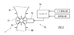
- FIG. 2 is a diagram showing a configuration of a control system of the exhaust heat recovery system shown in FIG.
- FIG. 3 is a partial schematic configuration diagram of an exhaust heat recovery system including a dust amount adjusting unit according to the first modification.
- FIG. 4 is a partial schematic configuration diagram of an exhaust heat recovery system including a dust amount adjustment unit according to the second modification.
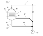
- FIG. 5 is a partial schematic configuration diagram of an exhaust heat recovery system including a dust amount adjustment unit according to Modification 3.
- FIG. 6 is a graph showing the relationship between the flow passage cross-sectional area of the small diameter portion of the dust exhaust pipe and the maximum value of the dust passage amount.
- FIG. 1 is a systematic schematic configuration diagram showing a cement manufacturing facility including an exhaust heat recovery system 1 according to an embodiment of the present invention
- FIG. 2 is a configuration of a control system of the exhaust heat recovery system 1 shown in FIG. It is a figure which shows.
- an exhaust heat recovery system 1 is shown with a cement firing plant 2.
- the cement calcination plant 2 is responsible for a calcination step of calcination of an intermediate product, a clinker, from a cement raw material.
- the cement firing plant 2 includes a preheater 21 and a calcining furnace 22 for preheating the cement raw material, a rotary kiln 23 for firing the preheated cement raw material, and an air quenching cooler (not shown) for cooling the fired product.
- the preheater 21 is a suspension preheater equipped with a plurality of stages of cyclone dust collectors connected in series.
- the exhaust gas from the rotary kiln 23 moves in sequence from the lowermost cyclone dust collector to the uppermost cyclone dust collector, and the cement raw material moves from the uppermost cyclone dust collector to the lowermost cyclone dust collector. Move in order toward the dust collector.
- the cement raw material is preheated while passing through a plurality of cyclone dust collectors.
- Cyclone dust collector at the bottom of the preheater 21 is connected to the calcination furnace 22.
- the outlet of the calcination furnace 22 is connected to the inlet of the rotary kiln 23.
- the cement raw material discharged from the preheater 21 is calcined in an atmosphere of about 900°C.
- the rotary kiln 23 is a horizontally long cylindrical rotary kiln, and is installed with a slight downward slope from the raw material inlet to the raw material outlet.
- the cement raw material calcined in the calcining furnace 22 is calcined.
- the high temperature fired product from the rotary kiln 23 is rapidly cooled by an air quenching cooler and becomes a clinker.
- the preheater exhaust gas line 9 from which the exhaust gas from the preheater 21 flows is connected to the preheater 21.
- the exhaust heat recovery system 1 is configured in the preheater exhaust gas line 9.
- the exhaust heat recovery system 1 includes an exhaust heat boiler 91, an attraction fan 92, a dust collector 94, an exhaust fan 95, and a chimney 96, which are provided in order from the upstream side of the exhaust gas flow.
- the raw material mill 93 is provided between the induction fan 92 and the dust collector 94. These elements are connected by pipes, ducts, or the like.
- the exhaust heat boiler 91 is provided in the housing 81, the exhaust gas inlet 82 provided in the upper part of the housing 81, the exhaust gas outlet 83 provided in the lower part of the housing 81, the bottom of the housing 81 and below the exhaust gas outlet 83. It also has a dust outlet 84 and a heat transfer tube 85 provided in the housing 81 to recover the heat of the exhaust gas.
- the exhaust gas flowing into the exhaust heat boiler 91 is a dust-containing gas containing a high concentration of particulate dust.
- the dust gas contains particulate dust having an average particle size of 10 ⁇ m or less at an average of 100 g / Nm 3 .
- the dust-containing gas adheres to the heat transfer tube 85 while flowing through the exhaust heat boiler 91 from the top to the bottom.
- the exhaust heat boiler 91 includes a dust removing device (not shown) such as a hammer or a soot blower.
- the dust adhering to the heat transfer tube 85 is peeled off by the dust removing device, and the peeled dust is deposited on the bottom of the housing 81.
- the bottom of the housing 81 may be formed of a dust hopper so that dust can be easily collected.
- the exhaust heat boiler 91 is provided with a dust amount detector 89 that detects the amount of dust accumulated on the bottom of the housing 81.
- the dust amount detector 89 may be a level sensor that detects the height of accumulated dust.
- the dust amount detector 89 may be a mass meter that detects the mass of the accumulated dust.
- An induction fan 92 is provided on the downstream side of the exhaust heat boiler 91.
- the exhaust gas outlet 83 of the exhaust heat boiler 91 and the inlet of the induction fan 92 are connected by an exhaust pipe 87.
- the dust outlet 84 of the exhaust heat boiler 91 and the inlet of the induction fan 92 are connected by a dust pipe 88.
- the exhaust gas outlet 83 is provided at a position different from the dust outlet 84, and the exhaust pipe 87 is independent of the dust exhaust pipe 88.
- the dust pipe 88 is provided with a dust amount adjusting unit 7 that adjusts the amount of dust sent to the induction fan 92 through the dust pipe 88.
- the dust amount adjusting unit 7 includes a flow passage area varying device 70 that changes the flow passage cross-sectional area of at least a portion of the dust discharge pipe 88.
- the flow path area varying device 70 includes a casing 71 forming a part of the dust pipe 88, a movable flow path member 72 housed in the casing 71, an actuator 73 for driving the movable flow path member 72, and an operation of the actuator 73. And a controller 74 for controlling the.
- the movable flow path member 72 may be, for example, a member that sends out dust such as a rotary valve rotor, or a member that changes the flow path cross-sectional area of a dust discharge pipe 88 such as a gate of a gate valve.
- the controller 74 adjusts the operation of the actuator 73 to change the amount of dust passing through the dust amount adjusting unit 7 within a predetermined range including zero.
- the movable flow path member 72 is a rotor of a rotary valve
- the amount of dust passing through increases as the rotation speed of the rotor increases, and the amount of dust passing decreases as the rotation speed of the rotor decreases.
- the rotation of is stopped, the amount of dust passing through becomes zero.
- the movable flow path member 72 is the gate of the gate valve
- the amount of dust passing through increases when the opening of the gate becomes large, and the amount of dust passing through decreases when the opening of the gate becomes small.
- the amount of dust passing through becomes zero.
- the amount of dust sent to the attraction fan 92 through the dust discharge pipe 88 can be adjusted.
- the exhaust gas discharged from the preheater 21 to the preheater exhaust gas line 9 flows into the exhaust heat boiler 91 and exchanges heat with the heat medium flowing through the heat transfer tube 85. In this way, the heat of the exhaust gas is recovered in the heat medium.
- Exhaust gas from which a part of the dust accompanying while passing through the exhaust heat boiler 91 has been dedusted passes through the exhaust pipe 87 and the attraction fan 92 and flows into the raw material mill 93.
- the raw material mill 93 uses the inflowing exhaust gas to dry and crush the cement raw material.
- the exhaust gas emitted from the raw material mill 93 flows into the dust collector 94.
- the dust collector 94 separates dust from the inflowing exhaust gas and collects it.
- the dust collected by the dust collector 94 is sent to the cement firing plant 2 and used as a cement raw material.
- the exhaust gas emitted from the dust collector 94 is discharged to the atmosphere through the exhaust fan 95 and the chimney 96.
- the dust removal device operates periodically, so that the dust adhering to the heat transfer tube 85 is peeled off from the heat transfer tube 85 and accumulated on the bottom of the heat transfer boiler 91.
- the controller 74 of the dust amount adjusting unit 7 constantly monitors the amount of dust detected by the dust amount detector 89.
- the controller 74 sends a control signal to the actuator 73 and moves the movable flow path member 72 so that the passage of dust is permitted.
- the dust accumulated on the bottom of the exhaust heat boiler 91 passes through the dust amount adjusting unit 7 by a predetermined emission amount and flows to the attraction fan 92 through the dust exhaust pipe 88.
- the amount of dust discharged is a value at which the load of the attraction fan 92 that sucks in and discharges the exhaust gas passing through the exhaust pipe 87 and the dust passing through the dust pipe 88 is equal to or less than a predetermined load threshold value.
- the amount of dust discharged as described above may be determined in advance and stored in the controller 74.
- the attraction fan 92 may be provided with a load detector 77 for detecting the load, and the controller 74 may obtain the amount of dust discharged so that the load detected by the load detector 77 does not exceed a predetermined load threshold value. Good.
- the load detector 77 include an ammeter that detects the drive current of the motor included in the attraction fan 92 and a torque meter that detects the rotational torque of the attraction fan 92.
- the controller 74 sends a control signal to the actuator 73 to move the movable flow path member 72 so that the passage of dust is blocked.
- the lower threshold is a value smaller than the upper threshold and may be zero. In this way, when the dust amount becomes equal to or lower than the lower threshold value, the feeding of dust through the dust discharge pipe 88 is stopped.
- the exhaust heat recovery system 1 of the present embodiment is the exhaust heat recovery system 1 that recovers heat from the exhaust gas of the preheater 21 of the cement firing plant 2, and includes the housing 81 and the upper part of the housing 81.
- the exhaust heat boiler 91 having the heat transfer tube 85 for recovering the heat of the above, the attracting fan 92 that attracts the exhaust gas to the exhaust heat boiler 91 and discharges the exhaust gas from the exhaust heat boiler 91, and the exhaust gas outlet 83 and the inlet of the attracting fan 92.
- a dust amount adjusting unit 7 that connects the exhaust pipe 87 to be connected, the dust outlet 84, and the inlet of the attraction fan 92, and adjusts the amount of dust passing through so that the load of the attraction fan 92 is equal to or less than a predetermined load threshold. It is provided with a dust exhaust pipe 88 to have.
- the dust accumulated on the bottom of the exhaust heat boiler 91 passes through the exhaust pipe 88 together with the exhaust gas and is sent to the dust collector 94 through the attraction fan 92 on the wake side. It is separated from the exhaust gas by the dust collector 94 and recovered. Therefore, the exhaust heat recovery system 1 does not require a dust conveyor for discharging the dust accumulated in the exhaust heat boiler 91. Therefore, as compared with the case where the dust conveyor is introduced into the exhaust heat recovery system 1, the initial introduction cost, the operation cost, and the maintenance cost can be reduced, and the system can be miniaturized.
- the exhaust heat recovery system 1 Normally, the amount of dust that accumulates on the bottom of the exhaust heat boiler 91 suddenly increases when soot blowing or hammering is performed. Therefore, in the exhaust heat recovery system 1, the amount of dust flowing from the exhaust heat boiler 91 to the induction fan 92 is limited by the dust amount adjusting unit 7. As a result, a sudden load increase or trip of the attraction fan 92 due to a large amount of dust flowing into the attraction fan 92 at once is avoided, and the exhaust heat recovery system 1 can continue stable operation.
- the exhaust heat recovery system 1 further includes a dust amount detector 89 for detecting the amount of dust accumulated on the bottom of the housing 81 of the exhaust heat boiler 91. Good.
- the dust amount adjusting unit 7 adjusts the flow path cross-sectional area of the dust discharge pipe 88 so as to allow the passage of dust until the dust amount becomes equal to or less than the predetermined lower threshold value.
- the flow path area varying device 70 for changing may be included.
- the dust amount adjusting unit 7 operates only when the amount of dust accumulated on the bottom of the exhaust heat boiler 91 exceeds the upper threshold value, and is attracted through the dust exhaust pipe 88 until the amount of dust falls below the lower threshold value. Dust is sent to the fan 92.
- the exhaust heat recovery system 1 may further include a load detector 77 that detects the load of the attraction fan 92.
- the dust amount adjusting unit 7 determines the amount of dust passing by changing the flow path cross-sectional area of the dust discharge pipe 88 so that the load detected by the load detector 77 does not exceed a predetermined load threshold value. It may include a channel area varying device 70 for increasing or decreasing.
- the present invention may include modified details of the specific structure and / or function of the above embodiment without departing from the idea of the present invention. ..
- the dust amount adjusting unit 7 of the exhaust heat recovery system 1 according to the above embodiment can be modified.
- FIG. 3 is a partial schematic configuration diagram of the exhaust heat recovery system 1 including the dust amount adjustment unit 7A according to the first modification.
- the same or similar members as those of the above-described embodiment are designated by the same reference numerals in the drawings, and the description thereof will be omitted.
- the dust amount adjusting unit 7A includes a throttle unit 78 provided at at least one position of the dust exhaust pipe 88.
- the restricting portion 78 may be a fixed restrictor having a constant flow passage cross-sectional area or a variable restrictor having a variable flow passage cross-sectional area.
- the flow passage cross-sectional area of the throttle 78 is smaller than the flow passage cross-sectional area of the remaining portion of the dust pipe 88. As described above, since the dust pipe 88 is provided with the throttle 78, the amount of dust passing through the throttle 78 is limited.
- the flow passage cross-sectional area of the throttle portion 78 allows the dust of a predetermined dust discharge amount or less to pass when the induction fan 92 is in the rated operation.
- a channel cross-sectional area can be obtained by simulation or experiment.
- the exhaust heat recovery system 1 may include the dust amount adjusting unit 7A according to the modified example 1 instead of the dust amount adjusting unit 7.
- the dust amount adjusting unit 7A according to the modified example 1 includes a throttle portion 78 provided at at least one location of the dust exhaust pipe 88, and the throttle portion 78 has a predetermined dust discharge amount when the induction fan 92 performs the rated operation. It has a flow passage cross-sectional area that allows dust to pass through the upper limit or less.
- the exhaust heat recovery system 1 including the dust amount adjusting unit 7A according to the modification 1 the amount of dust flowing from the exhaust heat boiler 91 to the attraction fan 92 is limited by the throttle unit 78. As a result, a sudden load increase or trip of the attraction fan 92 due to a large amount of dust flowing into the attraction fan 92 at once is avoided, and the exhaust heat recovery system 1 can continue stable operation. Further, in addition to the effects obtained by the exhaust heat recovery system 1 according to the above-described embodiment, it is possible to contribute to downsizing and cost reduction of the system.
- FIG. 4 is a partial schematic configuration diagram of an exhaust heat recovery system 1 including a dust amount adjustment unit 7B according to Modification 2.
- the same or similar members as those of the above-described embodiment are designated by the same reference numerals in the drawings, and the description thereof will be omitted.
- the dust amount adjusting unit 7B includes a plurality of dust discharge branch pipes 88a and 88b connected to the bottom portion of the housing 81 of the heat exhaust boiler 91.
- the plurality of dust discharge branch pipes 88a and 88b form a part of the dust discharge pipes 88a and 88b.
- the plurality of dust exhaust branch pipes 88a and 88b are connected to the main pipe 88c of the dust exhaust pipe 88, and the main pipe 88c is connected to the inlet of the attraction fan 92.
- Each of the dust branch pipes 88a and 88b has a sufficiently small flow path cross-sectional area as compared with the exhaust pipe 87.
- the total of the flow path cross-sectional areas of the plurality of dust discharge branch pipes 88a and 88b corresponds to the flow path cross-sectional area through which the dust equal to or less than the predetermined dust discharge amount upper limit value is passed when the attraction fan 92 performs the rated operation.
- a flow path area variable device 70 may be provided in at least one of the plurality of dust exhaust branch pipes 88a and 88b.
- the flow path area variable device 70 may have substantially the same configuration as that described in the embodiment.
- the dust discharge branch pipe 88a in which the flow path area varying device 70 is not provided is always open, and the dust and the exhaust gas are discharged through the dust discharge branch pipe 88a. Inflow to.
- the exhaust dust branch pipe 88b provided with the flow path area varying device 70 is closed in a steady state, and the amount of dust such as when the dust adhering to the heat transfer pipe 85 of the exhaust heat boiler 91 is peeled off.
- the flow passage cross-sectional area is expanded in a range in which the load of the induction fan 92 becomes equal to or less than a predetermined load threshold.
- the amount of dust passing through the dust exhaust pipe 88 is adjusted so that the load of the induction fan 92 becomes equal to or less than the predetermined load threshold.
- FIG. 5 is a partial schematic configuration diagram of an exhaust heat recovery system 1 including a dust amount adjustment unit 7C according to Modification 3.
- the same or similar members as those of the above-described embodiment are designated by the same reference numerals in the drawings, and the description thereof will be omitted.
- the dust amount adjusting unit 7C includes a small diameter portion 88d provided at at least one position of the dust exhaust pipe 88.
- the small-diameter portion 88d may be a part or a plurality of parts of the dust pipe 88, or the whole.
- the small-diameter portion 88d has a flow passage cross-sectional area through which dust of a predetermined dust discharge amount upper limit value or less passes through when the induction fan 92 performs the rated operation.
- the flow passage cross-sectional area of the small diameter portion 88d is sufficiently smaller than the flow passage cross-sectional area of the exhaust pipe 87. For example, when the diameter of the exhaust pipe 87 is 3000 mm, the diameter of the small diameter portion 88d of the dust discharge pipe 88 may be 500 mm.
- FIG. 6 is a graph showing the relationship between the flow passage cross-sectional area of the small diameter portion 88d of the dust exhaust pipe 88 and the maximum value of the dust passage amount.
- the horizontal axis of this graph represents the flow path cross-sectional area of the small diameter portion 88d of the dust pipe 88, and the vertical axis represents the maximum value of the dust passing amount of the dust pipe 88.
- dust does not flow until the flow passage cross-sectional area of the small diameter portion 88d is A1. Dust starts to flow when the flow passage cross-sectional area of the small-diameter portion 88d is A1, and when the flow passage cross-sectional area is A1 or more, the dust passage amount also increases.
- D1 be the amount of dust passing when a standard amount of dust is generated in normal operation
- D1 be the amount of dust passing when a large amount of dust suddenly flows into the attracting fan 92, causing a trip to the attracting fan 92.
- D2 be the amount of dust passing when a large amount of dust suddenly flows into the attracting fan 92, causing a trip to the attracting fan 92.
- D2 be the amount of dust passing when a large amount of dust suddenly flows into the attracting fan 92, causing a trip to the attracting fan 92.
- D2 the flow path cross-sectional area of the small diameter portion 88d of the dust discharge pipe 88 can be set between the flow path cross-sectional area A2 corresponding to the dust amount D1 and the flow path cross-sectional area A3 corresponding to the dust amount D2.
- the amount of dust flowing from the exhaust heat boiler 91 to the attraction fan 92 is limited by the small diameter portion 88d.
- a sudden load increase or trip of the attraction fan 92 due to a large amount of dust flowing into the attraction fan 92 at once is avoided, and the exhaust heat recovery system 1 can continue stable operation.
- Exhaust heat recovery system 2 Cement firing plant 9: Preheater exhaust gas line 21: Preheater 22: Temporary firing furnace 23: Rotary kiln 7, 7A, 7B, 7C: Dust amount adjusting unit 70: Flow path area variable device 71: Casing 72: Movable flow path member 73: Actuator 74: Controller 77: Load detector 78: Squeezing part 81: Housing 82: Exhaust gas inlet 83: Exhaust gas outlet 84: Dust outlet 85: Heat transfer tube 87: Exhaust pipe 88: Dust exhaust pipe 88a, 88b: Dust exhaust branch pipe 88c: Main 89: Dust amount detector 91: Exhaust heat boiler 92: Attracting fan 93: Raw material mill 94: Dust collector 95: Exhaust fan 96: Chimney
Landscapes
- Engineering & Computer Science (AREA)
- Chemical & Material Sciences (AREA)
- Ceramic Engineering (AREA)
- Physics & Mathematics (AREA)
- Thermal Sciences (AREA)
- Mechanical Engineering (AREA)
- General Engineering & Computer Science (AREA)
- Materials Engineering (AREA)
- Structural Engineering (AREA)
- Organic Chemistry (AREA)
- Environmental & Geological Engineering (AREA)
- Life Sciences & Earth Sciences (AREA)
- Sustainable Development (AREA)
- Sustainable Energy (AREA)
- Waste-Gas Treatment And Other Accessory Devices For Furnaces (AREA)
- Curing Cements, Concrete, And Artificial Stone (AREA)
Abstract
排熱回収システムは、排熱ボイラと、排熱ボイラへ排ガスを誘引し排熱ボイラから排ガスを排出させる誘引ファンと、排熱ボイラの排ガス出口と誘引ファンの入口とを接続する排気管と、排熱ボイラのダスト出口と誘引ファンの入口とを接続し、誘引ファンの負荷が所定の負荷閾値以下となるように通過するダストの量を調整するダスト量調整部を有する排塵管とを備える。
Description
本発明は、セメント焼成プラントのプレヒータの排ガスから熱を回収する排熱回収システムに関する。
従来から、セメント焼成プラントのサスペンションプレヒータの排ガスから熱を回収する排熱回収システムが知られている。特許文献1,2は、この種の排熱回収システムを開示する。
特許文献1の廃熱回収装置(排熱回収システム)は、サスペンションプレヒータからの排ガスの流れに沿って、排ガスの排熱を回収する排熱ボイラ、誘引ファン、バグフィルタ、及び煙突を備える。プレヒータの排ガスは、ダスト濃度が非常に高く、そのため、排熱ボイラの伝熱管表面に大量のダストが付着する。このダストはスートブローやハンマリングによって定期的に伝熱管表面から除去され、排熱ボイラの底部に堆積する。特許文献1の廃熱回収装置では、排熱ボイラの底部にダストを回収するダストホッパが設けられている。このダストホッパから排出されるダストは、ダストコンベヤによってセメント焼成プラントのロータリーキルンへ搬送され、セメント材料として利用される。
特許文献2の廃熱回収装置(排熱回収システム)は、サスペンションプレヒータからの排ガスの流れに沿って、排ガスの排熱を回収する排熱ボイラ、誘引ファン、バグフィルタ、及び煙突を備える。特許文献2の廃熱回収装置では、排熱ボイラの底部が後流側の誘引ファンの入口と接続されている。
排熱ボイラから排出されたダストは、一般に、特許文献1のようにダストコンベヤによってボイラの下方から搬出される。しかし、ダストコンベヤは、初期導入費用、運転費用、及びメンテナンス費用が嵩み、また、システムを大型化させる一因となる。一方で、特許文献2のように排熱ボイラの底部と誘引ファンとを単純に接続すると、排熱ボイラの伝熱管に付着しているダストが剥がれ落ちたときに、誘引ファンに一度に大量のダストが流入し、誘引ファンの急激な負荷上昇やトリップが生じる。
本発明は以上の事情に鑑みてされたものであり、その目的は、セメント焼成プラントのプレヒータの排ガスから熱を回収する排熱回収システムにおいて、排熱ボイラからダストを搬出するダストコンベヤを省略し且つシステムの安定した運転を継続することにある。
本発明の一態様に係る排熱回収システムは、セメント焼成プラントのプレヒータの排ガスから熱を回収する排熱回収システムであって、
筐体、前記筐体の上部に設けられた排ガス入口、前記筐体の下部に設けられた排ガス出口、前記筐体の底部且つ前記排ガス出口より下方に設けられたダスト出口、及び、前記筐体内に設けられた伝熱管を有する排熱ボイラと、
前記排熱ボイラへ前記排ガスを誘引し前記排熱ボイラから前記排ガスを排出させる誘引ファンと、
前記排ガス出口と前記誘引ファンの入口とを接続する排気管と、
前記ダスト出口と前記誘引ファンの前記入口とを接続し、前記誘引ファンの負荷が所定の負荷閾値以下となるように通過するダストの量を調整するダスト量調整部を有する排塵管と、を備えるものである。
筐体、前記筐体の上部に設けられた排ガス入口、前記筐体の下部に設けられた排ガス出口、前記筐体の底部且つ前記排ガス出口より下方に設けられたダスト出口、及び、前記筐体内に設けられた伝熱管を有する排熱ボイラと、
前記排熱ボイラへ前記排ガスを誘引し前記排熱ボイラから前記排ガスを排出させる誘引ファンと、
前記排ガス出口と前記誘引ファンの入口とを接続する排気管と、
前記ダスト出口と前記誘引ファンの前記入口とを接続し、前記誘引ファンの負荷が所定の負荷閾値以下となるように通過するダストの量を調整するダスト量調整部を有する排塵管と、を備えるものである。
このように、本発明に係る排熱回収システムでは、排熱ボイラの底部に堆積したダストは、排ガスと共に排塵管を通じて後流側の誘引ファンを通過する。よって、上記排熱回収システムでは、排熱ボイラに堆積したダストを排出するためのダストコンベヤを省略することができる。
排熱ボイラの底部に堆積するダストの量は、スートブローやハンマリングを行った際に一気に増加する。そのため、一般には、ダストが排熱ボイラから後流側へ排ガスに同伴して排出されると、誘引ファンに一度に大量のダストが流入し、誘引ファンの急激な負荷上昇やトリップが生じる。これに対し、本発明に係る排熱回収システムでは、排熱ボイラから誘引ファンへ流れるダスト量がダスト量調整部によって制限されるので、誘引ファンの急激な負荷変動が回避され、安定した運転を継続することができる。
本発明によれば、セメント焼成プラントのプレヒータの排ガスから熱を回収する排熱回収システムにおいて、排熱ボイラからダストを搬出するダストコンベヤを省略し且つシステムの安定した運転を継続することができる。
次に、図面を参照して本発明の実施の形態を説明する。図1は、本発明の一実施形態に係る排熱回収システム1を含むセメント製造設備を示す系統的概略構成図であり、図2は、図1に示す排熱回収システム1の制御系統の構成を示す図である。図1では、排熱回収システム1がセメント焼成プラント2と共に示されている。
〔セメント焼成プラント2〕
セメント焼成プラント2は、セメント原料から中間製品であるクリンカを焼成する焼成工程を担う。セメント焼成プラント2は、セメント原料を予熱するプレヒータ21及び仮焼炉22と、予熱されたセメント原料を焼成するロータリキルン23と、焼成物を冷却する図示されないエアクエンチングクーラとを含む。
セメント焼成プラント2は、セメント原料から中間製品であるクリンカを焼成する焼成工程を担う。セメント焼成プラント2は、セメント原料を予熱するプレヒータ21及び仮焼炉22と、予熱されたセメント原料を焼成するロータリキルン23と、焼成物を冷却する図示されないエアクエンチングクーラとを含む。
プレヒータ21は、直列的に接続された複数段のサイクロン集塵器を備えたサスペンションプレヒータである。このプレヒータ21では、ロータリキルン23からの排ガスが最下段のサイクロン集塵器から最上段のサイクロン集塵器へ向けて順に移動し、セメント原料が最上段のサイクロン集塵器から最下段のサイクロン集塵器へ向けて順に移動する。セメント原料は、複数のサイクロン集塵器を通過するうちに予熱される。
プレヒータ21の最下段のサイクロン集塵器は、仮焼炉22と接続されている。仮焼炉22の出口は、ロータリキルン23の入口と接続されている。仮焼炉22では、プレヒータ21を出たセメント原料が、約900℃の雰囲気で仮焼される。ロータリキルン23は、横長の円筒型の回転窯であって、原料入口から原料出口へ向かって僅かに下る勾配を付けて設置されている。ロータリキルン23では、仮焼炉22で仮焼されたセメント原料を焼成する。ロータリキルン23から出た高温の焼成物は、エアクエンチングクーラで急冷され、クリンカとなる。
〔排熱回収システム1〕
プレヒータ21には、プレヒータ21からの排ガスが流れ出すプレヒータ排ガスライン9が接続されている。排熱回収システム1は、プレヒータ排ガスライン9に構成されている。排熱回収システム1は、排ガスの流れの上流側から順に設けられた排熱ボイラ91、誘引ファン92、集塵機94、排風ファン95、及び煙突96を備える。本実施形態では、誘引ファン92と集塵機94との間に原料ミル93が設けられている。これらの要素の間は配管やダクト等により接続されている。
プレヒータ21には、プレヒータ21からの排ガスが流れ出すプレヒータ排ガスライン9が接続されている。排熱回収システム1は、プレヒータ排ガスライン9に構成されている。排熱回収システム1は、排ガスの流れの上流側から順に設けられた排熱ボイラ91、誘引ファン92、集塵機94、排風ファン95、及び煙突96を備える。本実施形態では、誘引ファン92と集塵機94との間に原料ミル93が設けられている。これらの要素の間は配管やダクト等により接続されている。
排熱ボイラ91は、筐体81、筐体81の上部に設けられた排ガス入口82、筐体81の下部に設けられた排ガス出口83、筐体81の底部且つ排ガス出口83より下方に設けられたダスト出口84、及び、筐体81内に設けられ排ガスの熱を回収する伝熱管85を有する。
排熱ボイラ91に流入する排ガスは、粒子状のダストを高濃度で含む含塵ガスである。一例として、粉塵ガスは、平均粒径が10μm以下の粒子状のダストを平均100g/Nm3で含む。含塵ガスは排熱ボイラ91を上から下へ向けて流れるうちに、伝熱管85に付着する。排熱ボイラ91は、ハンマやスートブロワなどの図示しないダスト除去装置を備える。ダスト除去装置によって伝熱管85に付着しているダストが剥がされ、剥がされたダストは筐体81の底部に堆積する。筐体81の底部は、ダストを捕集しやすいようにダストホッパで形成されていてよい。
排熱ボイラ91には、筐体81の底部に堆積したダストの量を検出するダスト量検出器89が設けられている。ダスト量検出器89は、堆積したダストの高さを検出するレベルセンサであってよい。或いは、ダスト量検出器89は、堆積したダストの質量を検出する質量計であってよい。
排熱ボイラ91の後流側には誘引ファン92が設けられている。排熱ボイラ91の排ガス出口83と誘引ファン92の入口とが排気管87で接続されている。排熱ボイラ91のダスト出口84と誘引ファン92の入口とが排塵管88で接続されている。排ガス出口83はダスト出口84とは異なる位置に設けられており、排気管87は排塵管88から独立している。
排塵管88には、排塵管88を通じて誘引ファン92へ送られるダストの量を調整するダスト量調整部7が設けられている。図2に示すように、本実施形態に係るダスト量調整部7は、排塵管88の少なくとも一部分の流路断面積を変化させる流路面積可変装置70を含む。流路面積可変装置70は、排塵管88の一部分を形成するケーシング71と、ケーシング71に収容された可動流路部材72と、可動流路部材72を駆動するアクチュエータ73と、アクチュエータ73の動作を制御するコントローラ74とを備える。可動流路部材72は、例えば、ロータリバルブのロータなどのダストを送り出す部材や、ゲート弁のゲートなどの排塵管88の流路断面積を変化させる部材であってよい。
上記構成のダスト量調整部7では、コントローラ74がアクチュエータ73の動作を調整することにより、ダスト量調整部7を通過するダストの量をゼロを含む所定の範囲内で変化させることができる。例えば、可動流路部材72がロータリバルブのロータである場合に、ロータの回転速度が上がると通過するダストの量が増大し、ロータの回転速度が下がると通過するダストの量が減少し、ロータの回転を停止すると通過するダストの量がゼロとなる。また、例えば、可動流路部材72がゲート弁のゲートである場合に、ゲートの開口が大きくなると通過するダストの量が増大し、ゲートの開口が小さくなると通過するダストの量が減少し、ゲートが閉じると通過するダストの量がゼロとなる。
上記のようにダスト量調整部7を通過するダストの量を調整することによって、排塵管88を通じて誘引ファン92へ送られるダストの量を調整することができる。
上記構成の排熱回収システム1において、プレヒータ21からプレヒータ排ガスライン9へ排出された排ガスは、排熱ボイラ91に流入して伝熱管85を流れる熱媒体と熱交換する。このようにして排ガスの熱が熱媒体に回収される。排熱ボイラ91を通過するうちに同伴するダストのうち一部が脱塵された排ガスは、排気管87、及び誘引ファン92を通過して、原料ミル93に流入する。原料ミル93は、流入した排ガスを利用してセメント原料を乾燥させながら粉砕する。原料ミル93から出た排ガスは、集塵機94へ流入する。集塵機94は、流入した排ガスからダストを分離して、回収する。集塵機94で回収されたダストは、セメント焼成プラント2へ送られ、セメント原料として利用される。集塵機94から出た排ガスは、排風ファン95及び煙突96を通じて大気へ放出される。
排熱ボイラ91では、ダスト除去装置が定期的に作動し、これにより伝熱管85に付着したダストが伝熱管85から剥がれ落ちて排熱ボイラ91の底部に堆積する。ダスト量調整部7のコントローラ74は、ダスト量検出器89で検出されたダスト量を常時監視している。
コントローラ74は、検出されたダスト量が予め記憶された上閾値を超えると、アクチュエータ73に制御信号を送り、ダストの通過が許容されるように可動流路部材72を動かす。これにより、排熱ボイラ91の底部に堆積していたダストが所定の排出量ずつダスト量調整部7を通過して、排塵管88を通じて誘引ファン92に流れる。ダストの排出量は、排気管87を通る排ガスと排塵管88を通るダストとを吸い込んで吐き出す誘引ファン92の負荷が、所定の負荷閾値以下となる値である。
上記のようなダストの排出量は、予め決定されてコントローラ74に記憶されていてよい。或いは、誘引ファン92に、その負荷を検出する負荷検出器77を設け、コントローラ74が、負荷検出器77で検出された負荷が所定の負荷閾値を超えないようなダストの排出量を求めてもよい。負荷検出器77としては、誘引ファン92に含まれるモータの駆動電流を検出する電流計、誘引ファン92の回転トルクを検出するトルク計が例示される。
コントローラ74は、監視しているダスト量が予め記憶された下閾値以下となると、アクチュエータ73に制御信号を送り、ダストの通過が阻止されるように可動流路部材72を動かす。下閾値は、上閾値より小さい値であり、ゼロであってもよい。このようにして、ダスト量が下閾値以下となると、排塵管88を通じたダストの送給が停止する。
以上に説明したように、本実施形態の排熱回収システム1は、セメント焼成プラント2のプレヒータ21の排ガスから熱を回収する排熱回収システム1であって、筐体81、筐体81の上部に設けられた排ガス入口82、筐体81の下部に設けられた排ガス出口83、筐体81の底部且つ排ガス出口83より下方に設けられたダスト出口84、及び、筐体81内に設けられ排ガスの熱を回収する伝熱管85を有する排熱ボイラ91と、排熱ボイラ91へ排ガスを誘引し排熱ボイラ91から排ガスを排出させる誘引ファン92と、排ガス出口83と誘引ファン92の入口とを接続する排気管87と、ダスト出口84と誘引ファン92の入口とを接続し、誘引ファン92の負荷が所定の負荷閾値以下となるように通過するダストの量を調整するダスト量調整部7を有する排塵管88とを備えるものである。
このように、本実施形態に係る排熱回収システム1では、排熱ボイラ91の底部に堆積したダストが、排ガスと共に排塵管88を通じて後流側の誘引ファン92を通過して集塵機94へ送られ、集塵機94で排ガスから分離されて回収される。よって、上記排熱回収システム1では、排熱ボイラ91に堆積したダストを排出するためのダストコンベヤを要しない。よって、排熱回収システム1にダストコンベヤを導入する場合と比較して、初期導入費用、運転費用、及びメンテナンス費用を削減することができ、また、システムを小型化することができる。
通常、排熱ボイラ91の底部に堆積するダストの量は、スートブローやハンマリングを行った際に一気に増加する。そこで、上記排熱回収システム1では、排熱ボイラ91から誘引ファン92へ流れるダスト量がダスト量調整部7によって制限される。これにより、誘引ファン92に大量のダストが一気に流入することに起因する誘引ファン92の急激な負荷上昇やトリップが回避され、排熱回収システム1は安定した運転を継続することができる。
また、本実施形態に示されるように、上記排熱回収システム1が、排熱ボイラ91の筐体81の底部に堆積しているダスト量を検出するダスト量検出器89を、更に備えていてよい。この場合のダスト量調整部7は、ダスト量が所定の上閾値を超えると、ダスト量が所定の下閾値以下となるまでダストの通過を許容するように排塵管88の流路断面積を変化させる流路面積可変装置70を含んでいてよい。
これにより、排熱ボイラ91の底部に堆積しているダスト量が上閾値を超えたときにのみダスト量調整部7が動作して、ダスト量が下閾値以下となるまで排塵管88を通じて誘引ファン92へダストが送られる。
また、本実施形態に示されるように、上記排熱回収システム1が、誘引ファン92の負荷を検出する負荷検出器77を、更に備えていてよい。この場合のダスト量調整部7は、負荷検出器77で検出された負荷が所定の負荷閾値を超えないように、排塵管88の流路断面積を変化させることにより通過するダストの量を増加又は減少させる流路面積可変装置70を含んでいてよい。
これにより、誘引ファン92の過負荷を確実に回避しながら、排熱ボイラ91の後流側へダストを流すことができる。
以上に本発明の好適な実施の形態を説明したが、本発明の思想を逸脱しない範囲で、上記実施形態の具体的な構造及び/又は機能の詳細を変更したものも本発明に含まれ得る。例えば、以下に説明するように、上記実施形態に係る排熱回収システム1のダスト量調整部7を変形させることができる。
〔ダスト量調整部7の変形例1〕
図3は、変形例1に係るダスト量調整部7Aを含む排熱回収システム1の一部概略構成図である。本変形例の説明においては、前述の実施形態と同一又は類似の部材には図面に同一の符号を付し、説明を省略する。
図3は、変形例1に係るダスト量調整部7Aを含む排熱回収システム1の一部概略構成図である。本変形例の説明においては、前述の実施形態と同一又は類似の部材には図面に同一の符号を付し、説明を省略する。
図3に示すように、変形例1に係るダスト量調整部7Aは、排塵管88の少なくとも1箇所に設けられた絞り部78を含む。絞り部78は、流路断面積が不変の固定絞りであってもよいし、流路断面積が可変な可変絞りであってもよい。
絞り部78の流路断面積は、排塵管88の余の部分の流路断面積と比較して小さい。このように、排塵管88に絞り部78が設けられることによって、絞り部78を通過するダスト量が制限される。
絞り部78の流路断面積は、誘引ファン92が定格運転しているときに所定のダスト排出量上限値以下のダストを通過させるものである。このような流路断面積は、シミュレーションにより、或いは、実験により求めることができる。
以上に説明した通り、前述の実施形態に係る排熱回収システム1は、ダスト量調整部7に代えて変形例1に係るダスト量調整部7Aを備えてよい。変形例1に係るダスト量調整部7Aは、排塵管88の少なくとも1箇所に設けられた絞り部78を含み、絞り部78が、誘引ファン92が定格運転をしたときに所定のダスト排出量上限値以下のダストを通過させる流路断面積を有する。
このように、変形例1に係るダスト量調整部7Aを備える排熱回収システム1では、排熱ボイラ91から誘引ファン92へ流れるダスト量が絞り部78によって制限される。これにより、誘引ファン92に大量のダストが一気に流入することに起因する誘引ファン92の急激な負荷上昇やトリップが回避され、排熱回収システム1は安定した運転を継続することができる。更に、前述の実施形態に係る排熱回収システム1で得られる効果に加えて、システムの小型化や低コスト化に寄与することができる。
〔ダスト量調整部7の変形例2〕
図4は、変形例2に係るダスト量調整部7Bを含む排熱回収システム1の一部概略構成図である。本変形例の説明においては、前述の実施形態と同一又は類似の部材には図面に同一の符号を付し、説明を省略する。
図4は、変形例2に係るダスト量調整部7Bを含む排熱回収システム1の一部概略構成図である。本変形例の説明においては、前述の実施形態と同一又は類似の部材には図面に同一の符号を付し、説明を省略する。
図4に示すように、変形例2に係るダスト量調整部7Bは、排熱ボイラ91の筐体81の底部に接続された複数の排塵枝管88a,88bを含む。複数の排塵枝管88a,88bは、排塵枝管88a,88bは排塵管88の一部を構成する。複数の排塵枝管88a,88bは排塵管88の本管88cと接続され、本管88cは誘引ファン92の入口と接続されている。
排塵枝管88a,88bの各々は、排気管87と比較して十分に小さい流路断面積を有する。複数の排塵枝管88a,88bの流路断面積の合計は、誘引ファン92が定格運転をしたときに所定のダスト排出量上限値以下のダストを通過させる流路断面積に相当する。
複数の排塵枝管88a,88bの少なくとも1つに、流路面積可変装置70が設けられていてよい。この流路面積可変装置70は、実施形態で説明したものと実質的に同一の構成を有していてよい。
上記変形例2に係るダスト量調整部7Bでは、流路面積可変装置70が設けられていない排塵枝管88aは常時開放されており、排塵枝管88aを通じてダスト及び排ガスが排塵管88に流入する。一方、流路面積可変装置70が設けられた排塵枝管88bは、定常時閉止されており、排熱ボイラ91の伝熱管85に付着しているダストが剥がれ落ちたときなどのダスト量が一気に増加したときに、誘引ファン92の負荷が所定の負荷閾値以下となる範囲で流路断面積が拡張される。これにより、誘引ファン92の負荷が所定の負荷閾値以下となるように、排塵管88を通過するダストの量が調整される。
〔ダスト量調整部7の変形例3〕
図5は、変形例3に係るダスト量調整部7Cを含む排熱回収システム1の一部概略構成図である。本変形例の説明においては、前述の実施形態と同一又は類似の部材には図面に同一の符号を付し、説明を省略する。
図5は、変形例3に係るダスト量調整部7Cを含む排熱回収システム1の一部概略構成図である。本変形例の説明においては、前述の実施形態と同一又は類似の部材には図面に同一の符号を付し、説明を省略する。
図5に示すように、変形例3に係るダスト量調整部7Cは、排塵管88の少なくとも1箇所に設けられた細径部88dを含む。細径部88dは、排塵管88の一部分又は複数部分、或いは、全体であってよい。細径部88dは、誘引ファン92が定格運転をしたときに所定のダスト排出量上限値以下のダストを通過させる流路断面積を有する。このような細径部88dの流路断面積は、排気管87の流路断面積と比較して十分に小さい。例えば、排気管87の直径が3000mmである場合に、排塵管88の細径部88dの直径を500mmとしてよい。
図6は、排塵管88の細径部88dの流路断面積とダスト通過量の最大値との関係を表すグラフである。このグラフの横軸が排塵管88の細径部88dの流路断面積を表し、縦軸が排塵管88のダスト通過量の最大値を表す。このグラフに示されるように、細径部88dの流路断面積がA1までは、ダストが流れない。細径部88dの流路断面積がA1でダストが流れ始め、A1以上で流路断面積の増加に伴ってダスト通過量も増加する。通常運転において標準的な量のダストが発生しているときのダスト通過量をD1とし、誘引ファン92に大量のダストが一気に流入することによって誘引ファン92にトリップが発生するときのダスト通過量をD2とする。排塵管88の細径部88dの流路断面積は、ダスト量D1に対応する流路断面積A2から、ダスト量D2に対応する流路断面積A3までの間で設定され得る。
変形例3に係るダスト量調整部7Cを備える排熱回収システム1では、排熱ボイラ91から誘引ファン92へ流れるダスト量が細径部88dによって制限される。これにより、誘引ファン92に大量のダストが一気に流入することに起因する誘引ファン92の急激な負荷上昇やトリップが回避され、排熱回収システム1は安定した運転を継続することができる。更に、前述の実施形態に係る排熱回収システム1で得られる効果に加えて、システムの小型化や低コスト化に寄与することができる。
1 :排熱回収システム
2 :セメント焼成プラント
9 :プレヒータ排ガスライン
21 :プレヒータ
22 :仮焼炉
23 :ロータリキルン
7,7A,7B,7C:ダスト量調整部
70 :流路面積可変装置
71 :ケーシング
72 :可動流路部材
73 :アクチュエータ
74 :コントローラ
77 :負荷検出器
78 :絞り部
81 :筐体
82 :排ガス入口
83 :排ガス出口
84 :ダスト出口
85 :伝熱管
87 :排気管
88 :排塵管
88a,88b :排塵枝管
88c :本管
89 :ダスト量検出器
91 :排熱ボイラ
92 :誘引ファン
93 :原料ミル
94 :集塵機
95 :排風ファン
96 :煙突
Claims (5)
- セメント焼成プラントのプレヒータの排ガスから熱を回収する排熱回収システムであって、
筐体、前記筐体の上部に設けられた排ガス入口、前記筐体の下部に設けられた排ガス出口、前記筐体の底部且つ前記排ガス出口より下方に設けられたダスト出口、及び、前記筐体内に設けられた伝熱管を有する排熱ボイラと、
前記排熱ボイラへ前記排ガスを誘引し前記排熱ボイラから前記排ガスを排出させる誘引ファンと、
前記排ガス出口と前記誘引ファンの入口とを接続する排気管と、
前記ダスト出口と前記誘引ファンの前記入口とを接続し、前記誘引ファンの負荷が所定の負荷閾値以下となるように通過するダストの量を調整するダスト量調整部を有する排塵管と、を備える、
排熱回収システム。 - 前記排熱ボイラの前記筐体の底部に堆積しているダスト量を検出するダスト量検出器を、更に備え、
前記ダスト量調整部は、前記ダスト量が所定の上閾値を超えると前記ダスト量が所定の下閾値以下となるまで前記ダストの通過を許容するように前記排塵管の流路断面積を変化させる流路面積可変装置を含む、
請求項1に記載の排熱回収システム。 - 前記誘引ファンの負荷を検出する負荷検出器を、更に備え、
前記ダスト量調整部は、前記負荷検出器で検出された負荷が所定の負荷閾値を超えないように、前記排塵管の流路断面積を変化させることにより通過する前記ダストの量を調整する流路面積可変装置を含む、
請求項1又は2に記載の排熱回収システム。 - 前記ダスト量調整部は、前記排塵管の少なくとも1箇所に設けられた絞り部を含み、前記絞り部が、前記誘引ファンが定格運転をしたときに所定のダスト排出量上限値以下のダストを通過させる流路断面積を有する、
請求項1に記載の排熱回収システム。 - 前記ダスト量調整部は、前記排塵管の少なくとも1箇所に設けられた細径部を含み、前記細径部が、前記誘引ファンが定格運転をしたときに所定のダスト排出量上限値以下のダストを通過させる流路断面積を有する、
請求項1に記載の排熱回収システム。
Priority Applications (1)
| Application Number | Priority Date | Filing Date | Title |
|---|---|---|---|
| JP2021504012A JP7114796B2 (ja) | 2019-03-07 | 2020-02-27 | 排熱回収システム |
Applications Claiming Priority (2)
| Application Number | Priority Date | Filing Date | Title |
|---|---|---|---|
| CN201910172347.7 | 2019-03-07 | ||
| CN201910172347.7A CN111664715B (zh) | 2019-03-07 | 2019-03-07 | 余热回收系统 |
Publications (1)
| Publication Number | Publication Date |
|---|---|
| WO2020179600A1 true WO2020179600A1 (ja) | 2020-09-10 |
Family
ID=72337054
Family Applications (1)
| Application Number | Title | Priority Date | Filing Date |
|---|---|---|---|
| PCT/JP2020/007966 Ceased WO2020179600A1 (ja) | 2019-03-07 | 2020-02-27 | 排熱回収システム |
Country Status (3)
| Country | Link |
|---|---|
| JP (1) | JP7114796B2 (ja) |
| CN (1) | CN111664715B (ja) |
| WO (1) | WO2020179600A1 (ja) |
Cited By (1)
| Publication number | Priority date | Publication date | Assignee | Title |
|---|---|---|---|---|
| JP2023181764A (ja) * | 2022-06-13 | 2023-12-25 | 東洋ガラス株式会社 | ガラス及び水素を製造するプラント、及びガラス及び水素の製造方法 |
Citations (4)
| Publication number | Priority date | Publication date | Assignee | Title |
|---|---|---|---|---|
| JPS6170383A (ja) * | 1984-09-10 | 1986-04-11 | 三菱重工業株式会社 | 廃熱回収装置 |
| JPS61122142A (ja) * | 1984-11-19 | 1986-06-10 | 三菱重工業株式会社 | セメント廃熱回収装置 |
| JP2007147119A (ja) * | 2005-11-25 | 2007-06-14 | Kawasaki Plant Systems Ltd | 多数の整流板を備えた反転式ダスト除去装置 |
| JP2013184852A (ja) * | 2012-03-08 | 2013-09-19 | Taiheiyo Cement Corp | セメントキルン排ガスの処理方法 |
Family Cites Families (10)
| Publication number | Priority date | Publication date | Assignee | Title |
|---|---|---|---|---|
| DE2657067C3 (de) * | 1976-12-14 | 1980-05-14 | Mannesmann Ag, 4000 Duesseldorf | Anlage zur Absaugung von mit Schadstoffen behafteter Luft aus Großbauten |
| JPS606905B2 (ja) * | 1981-06-06 | 1985-02-21 | 秩父セメント株式会社 | セメント焼成方法及びその装置 |
| CN201391625Y (zh) * | 2009-04-10 | 2010-01-27 | 东莞市慧达环保有限公司 | 除尘管道用风量调节阀 |
| CN202028288U (zh) * | 2011-03-31 | 2011-11-09 | 中国联合水泥集团有限公司南阳分公司 | 余热锅炉沉降室输灰控制装置 |
| CN204564333U (zh) * | 2014-12-26 | 2015-08-19 | 湖南金百大能效管理科技有限公司 | 自动除尘节能系统 |
| CN106224996B (zh) * | 2016-09-22 | 2018-04-03 | 成都建筑材料工业设计研究院有限公司 | 一种消除水泥窑焚烧废弃物的不稳定有害氯的系统 |
| CN206816310U (zh) * | 2017-03-13 | 2017-12-29 | 北京汉能清源科技有限公司 | 水泥炉窑余热锅炉蒸汽驱动高温除尘风机的传动节能装置 |
| CN207018209U (zh) * | 2017-06-05 | 2018-02-16 | 冯展锋 | 一种负载可调的离心风机 |
| CN107174927A (zh) * | 2017-07-13 | 2017-09-19 | 北京建筑材料科学研究总院有限公司 | 一种水泥回转窑的脱硝方法和系统 |
| CN210165773U (zh) * | 2019-03-07 | 2020-03-20 | 川崎重工业株式会社 | 余热回收系统 |
-
2019
- 2019-03-07 CN CN201910172347.7A patent/CN111664715B/zh active Active
-
2020
- 2020-02-27 JP JP2021504012A patent/JP7114796B2/ja active Active
- 2020-02-27 WO PCT/JP2020/007966 patent/WO2020179600A1/ja not_active Ceased
Patent Citations (4)
| Publication number | Priority date | Publication date | Assignee | Title |
|---|---|---|---|---|
| JPS6170383A (ja) * | 1984-09-10 | 1986-04-11 | 三菱重工業株式会社 | 廃熱回収装置 |
| JPS61122142A (ja) * | 1984-11-19 | 1986-06-10 | 三菱重工業株式会社 | セメント廃熱回収装置 |
| JP2007147119A (ja) * | 2005-11-25 | 2007-06-14 | Kawasaki Plant Systems Ltd | 多数の整流板を備えた反転式ダスト除去装置 |
| JP2013184852A (ja) * | 2012-03-08 | 2013-09-19 | Taiheiyo Cement Corp | セメントキルン排ガスの処理方法 |
Cited By (1)
| Publication number | Priority date | Publication date | Assignee | Title |
|---|---|---|---|---|
| JP2023181764A (ja) * | 2022-06-13 | 2023-12-25 | 東洋ガラス株式会社 | ガラス及び水素を製造するプラント、及びガラス及び水素の製造方法 |
Also Published As
| Publication number | Publication date |
|---|---|
| JP7114796B2 (ja) | 2022-08-08 |
| CN111664715A (zh) | 2020-09-15 |
| JPWO2020179600A1 (ja) | 2021-11-18 |
| CN111664715B (zh) | 2022-12-09 |
Similar Documents
| Publication | Publication Date | Title |
|---|---|---|
| JP5407262B2 (ja) | セメント焼成設備の排ガス処理方法および処理システム | |
| JP5157841B2 (ja) | セメント焼成設備の排ガス処理方法および処理システム | |
| CN101600666B (zh) | 水泥煅烧设备的排气处理方法及处理系统 | |
| US7316564B2 (en) | Method and installation for regulating the quantity of circulating solids in a circulating fluidized bed reactor system | |
| US5992041A (en) | Raining bed heat exchanger and method of use | |
| JP7114796B2 (ja) | 排熱回収システム | |
| WO2012067799A1 (en) | Vertical calcined petroleum coke incinerator | |
| JP3807741B1 (ja) | 多数の整流板を備えた反転式ダスト除去装置 | |
| CN114877663A (zh) | 一种焚烧炉炉渣烘干系统 | |
| US4909160A (en) | Temperature-controlled exhaust particulate collection system for high temperature material processing facility | |
| US20170115062A1 (en) | Apparatus for producing cement clinker | |
| CN210165773U (zh) | 余热回收系统 | |
| JP2010125378A (ja) | 石炭焚きボイラの燃焼ガス浄化システム及び石炭焚きボイラの燃焼ガス浄化システムの運転方法 | |
| CS219312B2 (en) | Method of dispersing the powderous material and device for executing the same method | |
| JPWO2020203247A1 (ja) | 排熱回収システム及びその運転方法 | |
| JP6562730B2 (ja) | 粉粒体の加熱処理装置及び廃石膏の加熱処理方法 | |
| JP2651769B2 (ja) | 熱回収燃焼設備 | |
| EP0815917A1 (en) | Equipment for separating solid particles from fumes or gases generated in industrial processes | |
| JP2002372217A (ja) | 旋回燃焼式流動層焼却炉 | |
| JP2017007906A (ja) | セメントクリンカの製造装置及び製造方法 | |
| JPH1160297A (ja) | セメントキルンの排ガス処理方法 | |
| JP2926493B1 (ja) | 流動層セメント焼成・制御方法及び装置 | |
| KR100887159B1 (ko) | 플라이 애시 분급장치 | |
| JPH11322074A (ja) | ダスト堆積防止装置 | |
| KR20220111830A (ko) | 포집부의 온도에 기초한 바이오매스 연소 파울링 제거 장치 |
Legal Events
| Date | Code | Title | Description |
|---|---|---|---|
| 121 | Ep: the epo has been informed by wipo that ep was designated in this application |
Ref document number: 20767129 Country of ref document: EP Kind code of ref document: A1 |
|
| ENP | Entry into the national phase |
Ref document number: 2021504012 Country of ref document: JP Kind code of ref document: A |
|
| NENP | Non-entry into the national phase |
Ref country code: DE |
|
| 122 | Ep: pct application non-entry in european phase |
Ref document number: 20767129 Country of ref document: EP Kind code of ref document: A1 |