WO2020179501A1 - 触媒粒子及びそれを用いた水素製造方法 - Google Patents
触媒粒子及びそれを用いた水素製造方法 Download PDFInfo
- Publication number
- WO2020179501A1 WO2020179501A1 PCT/JP2020/007070 JP2020007070W WO2020179501A1 WO 2020179501 A1 WO2020179501 A1 WO 2020179501A1 JP 2020007070 W JP2020007070 W JP 2020007070W WO 2020179501 A1 WO2020179501 A1 WO 2020179501A1
- Authority
- WO
- WIPO (PCT)
- Prior art keywords
- catalyst particles
- furnace
- catalyst
- hydrogen
- angle
- Prior art date
- Legal status (The legal status is an assumption and is not a legal conclusion. Google has not performed a legal analysis and makes no representation as to the accuracy of the status listed.)
- Ceased
Links
Classifications
-
- B—PERFORMING OPERATIONS; TRANSPORTING
- B01—PHYSICAL OR CHEMICAL PROCESSES OR APPARATUS IN GENERAL
- B01J—CHEMICAL OR PHYSICAL PROCESSES, e.g. CATALYSIS OR COLLOID CHEMISTRY; THEIR RELEVANT APPARATUS
- B01J23/00—Catalysts comprising metals or metal oxides or hydroxides, not provided for in group B01J21/00
- B01J23/70—Catalysts comprising metals or metal oxides or hydroxides, not provided for in group B01J21/00 of the iron group metals or copper
- B01J23/74—Iron group metals
- B01J23/745—Iron
-
- C—CHEMISTRY; METALLURGY
- C01—INORGANIC CHEMISTRY
- C01B—NON-METALLIC ELEMENTS; COMPOUNDS THEREOF; METALLOIDS OR COMPOUNDS THEREOF NOT COVERED BY SUBCLASS C01C
- C01B3/00—Hydrogen; Gaseous mixtures containing hydrogen; Separation of hydrogen from mixtures containing it; Purification of hydrogen; Reversible storage of hydrogen
- C01B3/02—Production of hydrogen; Production of gaseous mixtures containing hydrogen
- C01B3/22—Production of hydrogen; Production of gaseous mixtures containing hydrogen by decomposition of gaseous or liquid organic compounds
- C01B3/24—Production of hydrogen; Production of gaseous mixtures containing hydrogen by decomposition of gaseous or liquid organic compounds of hydrocarbons
- C01B3/28—Production of hydrogen; Production of gaseous mixtures containing hydrogen by decomposition of gaseous or liquid organic compounds of hydrocarbons using moving solid particles, e.g. fluidised bed technique
-
- B—PERFORMING OPERATIONS; TRANSPORTING
- B01—PHYSICAL OR CHEMICAL PROCESSES OR APPARATUS IN GENERAL
- B01J—CHEMICAL OR PHYSICAL PROCESSES, e.g. CATALYSIS OR COLLOID CHEMISTRY; THEIR RELEVANT APPARATUS
- B01J2235/00—Indexing scheme associated with group B01J35/00, related to the analysis techniques used to determine the catalysts form or properties
Definitions
- the present invention relates to catalyst particles for thermal decomposition of hydrocarbons and a hydrogen production method using the same, and more particularly to highly fluid catalyst particles and a hydrogen production method using the same.
- Patent Document 1 hydrogen is generated by heating a hydrocarbon-containing gas in the reaction vessel by using a continuous fixed-bed catalytic reaction apparatus including a reaction vessel containing a catalyst layer supported by a cage as a furnace. It is described that carbon monoxide, methane, etc. are produced.
- Patent Document 2 carbon nanotubes are generated on the catalyst particles by introducing a raw material gas containing a hydrocarbon such as ethylene into the rotary furnace together with the catalyst particles and heating the catalyst particles while flowing them by rotation. It is described about letting.
- Patent Document 3 describes a method for producing nanocarbon and hydrogen by modifying methane using a screw-type catalytic reaction apparatus provided as a furnace with a screw feeder in a reaction vessel.
- Patent Documents 2 and 3 the catalyst particles and the raw material gas are continuously introduced into the rotary furnace, while the carbon nanotubes or nanocarbons deposited on the catalyst are continuously discharged from the reaction vessel.
- the contact area of the catalyst with the raw material gas is gradually reduced to reduce the reaction efficiency, but in Patent Documents 2 and 3, the product is deposited. Since a fresh catalyst is introduced as the catalyst particles are discharged, a highly efficient reaction can be continuously maintained.
- Japanese Unexamined Patent Publication No. 2013-166106 Japanese Patent Publication No. 2013-518015 Japanese Unexamined Patent Publication No. 2011-116656
- the present invention has been made in view of the above problems, and an object of the present invention is to reduce adhesion of catalyst particles to the inner wall of a furnace in a reaction carried out by flowing catalyst particles in a furnace, which is desired.
- the purpose is to improve the production efficiency of the product.
- Another object of the present invention is to enable efficient production of hydrogen by using such catalyst particles.
- the catalyst particles have a high fluidity and are hard to adhere to the inner wall of the furnace.
- the catalyst particles according to the present invention are catalyst particles that are used by being heated while flowing in a furnace, and are characterized in that the collapse angle is 30 ° or less.
- the collapse angle which is one of the indicators of the fluidity of the particles, is 30 ° or less
- the fluidity is high, and the particles adhere to the inner wall of the furnace when used while flowing in the furnace. hard. Therefore, when the catalyst particles are continuously introduced into the furnace and discharged to the outside of the furnace, it is possible to prevent the catalyst particles from adhering to and staying in the furnace. Further, since the fluidity is high as described above, the contact with the raw material gas in the furnace can be improved, and the reaction for obtaining a desired product can be efficiently promoted.
- the catalyst particles according to the present invention preferably have a spatula angle of 58 ° or less.
- the catalyst particles have a collapse angle of 30 ° or less, and have a spatula angle of 58 ° or less, which is one of the indicators of the fluidity of the particles as well as the collapse angle.
- the effect of preventing adhesion in the furnace can be improved.
- the method for producing hydrogen according to the present invention includes a step of injecting catalyst particles having a collapse angle of 30 ° or less and a raw material gas containing a hydrocarbon into the furnace, and the catalyst while flowing the catalyst particles in the furnace.
- the method is characterized by including a step of heating the particles and the raw material gas, and a step of recovering hydrogen generated by the heating.
- catalyst particles having a collapse angle of 30 ° or less which is one of the indicators of particle fluidity, are used, so that the catalyst particles adhere to and stay in the furnace as described above. Can be prevented. Therefore, since the contactability of the catalyst particles with the raw material gas containing the hydrocarbon can be improved, the reaction in which the catalyst particles efficiently generate hydrogen from the hydrocarbon can be promoted. As a result, the yield of hydrogen can be improved.
- the catalyst particles preferably have a spatula angle of 58° or less.
- the catalyst particles have a collapse angle of 30 ° or less, and a spatula angle, which is one of the indicators of the fluidity of the particles as well as the collapse angle, is 58 ° or less. It is excellent, and the effect of preventing the adhesion of the catalyst particles in the furnace can be improved. Therefore, the contact property of the catalyst particles with respect to the source gas can be further improved, and the yield of hydrogen can be further improved.
- the furnace may be a rotary kiln.
- the catalyst particles having high fluidity can be used to improve the effect of preventing the catalyst particles from adhering to the inside of the furnace. This is especially effective when using a rotary kiln that allows the particles to flow by rotation.
- hydrogen may be generated by a direct methane reforming (DMR) reaction.
- DMR direct methane reforming
- the catalyst particles having high fluidity can be used to improve the effect of preventing the catalyst particles from adhering to the inside of the furnace.
- the reaction can be promoted by efficiently contacting them.
- DMR is useful in that carbon oxide gas such as carbon dioxide is not generated.
- the catalyst particles according to the present invention since the catalyst particles have high fluidity, the adhesion of the catalyst particles into the furnace can be reduced and the contact with the raw material gas can be improved. Since the catalyst particles can efficiently promote the hydrogen production reaction, the hydrogen production efficiency can be improved.
- the catalyst particles according to the present invention are characterized by having a collapse angle of 30 ° or less, and are used for heating while flowing in a furnace. As an example, they are used as catalyst particles for hydrocarbon pyrolysis. Be done.
- the collapse angle of the catalyst particles according to the present invention is preferably 20° to 28°.
- the collapse angle is used as one of the indexes of the fluidity of particles, and is represented by the angle formed by the slope (ridge line) and the horizontal plane when the mountain-shaped particle layer collapses due to an impact. Specifically, particles are dropped onto a table through a funnel or the like to form a mountain-shaped particle layer, and then the slope and horizontal plane (surface of the table) of the particle layer collapsed by applying a predetermined impact. It is represented by the angle between the two. The higher the fluidity of particles, the flatter the collapsed mountain-shaped particle layer is, and the collapsed angle becomes smaller.
- the catalyst particles according to the present invention have a high collapseability because the collapse angle is as small as 30° or less. Therefore, when used for the purpose of heating while flowing in the furnace, it is difficult to adhere to the inner wall of the furnace. Therefore, when the catalyst particles are continuously introduced into the furnace and discharged to the outside of the furnace, it is possible to prevent the catalyst particles from adhering to and staying in the furnace. Further, since the fluidity is high, the contact property with the raw material gas reacted by heating in the furnace can be improved, and the reaction for obtaining a desired product can be efficiently promoted.
- the catalyst particles according to the present invention preferably have a spatula angle of 58 ° or less, and more preferably a spatula angle of 47 ° to 57 °.
- the spatula angle is used as one of the indicators of particle fluidity as well as the collapse angle.
- the spatula angle is the slope (ridgeline) and horizontal plane (surface of the spatula) of the particle layer deposited on the spatula by slowly lifting the spatula after laminating the particle layer on the spatula (spatula).
- the angle formed is A
- the angle formed by the slope of the particle layer collapsed by a predetermined impact and the (ridge line) and the horizontal plane (surface of the spatula) is B, it is represented by (A + B) / 2.
- the present invention also covers a method for producing hydrogen using catalyst particles having the above characteristics.
- a catalyst particle having the above characteristics and a raw material gas containing a hydrocarbon are charged into a furnace, and the catalyst particle and the raw material gas are heated while flowing the catalyst particle in the furnace. It is characterized by recovering the hydrogen generated by. Since the hydrogen production method according to the present invention uses the catalyst particles having the above characteristics, the catalyst particles can be efficiently flowed in the furnace and the contact with the raw material gas can be improved. As a result, the catalytic action of the catalyst particles can be efficiently exhibited, and the hydrogen yield can be improved.
- hydrogen is generated via a catalyst by introducing a raw material gas, and if the catalyst particles can be flowed, particularly the structure of the apparatus and It is not limited to the principle and can be selected. Specifically, a flow bed of a mechanism for processing by flowing the processed material up and down in a vertically provided reaction tube, and a mechanism for transporting and flowing the processed material in the horizontal direction by installing a horizontally long reaction tube.
- the catalyst is flowed by the raw material gas blown up from below, in the screw type tubular furnace, the catalyst and the raw material gas are mixed by the screw, and in the rotary kiln, the displacement is caused by rotation. Alternatively, it is carried out by scraping the catalyst by flight.
- any of batch type, continuous type, batch continuous type, and the like can be adopted, but these are not particularly limited.
- a rotary furnace such as a rotary kiln in which there is a problem that catalyst particles adhere to the furnace wall in the furnace, particularly when using a continuous type or batch continuous type rotary kiln, high fluidity of the catalyst particles of the present invention is obtained. The effect obtained by can be shown higher.
- the raw material gas propane gas, liquefied natural gas (LNG), city gas, hydrocarbon gas such as pure methane, etc. are used, and hydrogen and solid carbon are produced by thermal decomposition of hydrocarbon through a catalyst.
- hydrogen, an inert gas, or an oxidizing gas may be mixed with the raw material gas for the purpose of adjusting the concentration of the raw material gas, preventing deactivation of the catalyst, and the like.
- the concentration of the raw material gas contained in the gas introduced into the reaction field is preferably 60 vol% or more, more preferably 90 vol% or more, and further preferably 95 vol% or more.
- methane direct reforming (DMR) reaction in which methane gas is directly pyrolyzed into solid carbon and hydrogen.
- methane is decomposed by heating methane gas together with a catalyst to produce hydrogen gas and solid carbon.
- This reaction is useful in that carbon dioxide gas such as carbon dioxide is not generated.
- solid carbon is produced in the form of being laminated on the surface of catalyst particles, and its shape and crystallinity depend on the reaction conditions such as the catalyst, but at least part of it is fibrous crystalline carbon such as carbon nanotubes. It is preferable to have.
- the catalyst particles used in the present invention have the above characteristics, and their composition is not particularly limited as long as they produce hydrogen and solid carbon by thermal decomposition of hydrocarbons, for example, Fe, Co, Ni and A metal compound such as an oxide of these metal elements, a metal support, a support of a metal compound, or a physical mixture thereof, which contains one or more of Mn, can be used.
- a metal compound such as an oxide of these metal elements, a metal support, a support of a metal compound, or a physical mixture thereof, which contains one or more of Mn, can be used.
- Al or Mg may be contained in order to increase the production amount of hydrogen.
- the range of particle diameter is not particularly limited as long as it flows in the furnace, but the median diameter (d50) is preferably 1 ⁇ m to 1 mm, particularly preferably 2.5 ⁇ m to 200 ⁇ m.
- Various treatment methods can be used for adjusting the powder properties of the catalyst particles used in the present invention.
- the treatment apparatus include a cutter mill for crushing by shear stress, crushing by a pin mill method, and compression shearing. Adjusting the particle size and particle properties with a stone mill type crusher (glow mill, mascoroider, etc.) that crushes by stress, sand mill, mix maller, hammer mill (jo crusher) that crushes by impact, jet mill that is an air flow type crusher Is possible.
- a stone mill type crusher low mill, mascoroider, etc.
- jo crusher hammer mill
- a continuous rotary kiln having a diameter of 250 mm is prepared as a furnace, catalyst particles made of iron oxide and having a collapse angle of 30 ° or less are used as catalyst particles, and methane gas is used as a hydrocarbon.
- the catalyst particles are continuously supplied into the rotary kiln at 0.01 g / min to 7.5 g / min, and methane gas is continuously supplied at 0.5 L / min to 50 L / min.
- the gas injection method multiple stages may be charged.
- the supplied catalyst particles and methane gas are heated in a rotary kiln at a temperature of 400°C to 800°C.
- methane is thermally decomposed in the furnace via a catalyst to generate hydrogen and solid carbon.
- the generated catalyst particles in which hydrogen and solid carbon are laminated on the surface are continuously discharged from a discharge port provided on the opposite side of the supply port provided at one end of the rotary kiln.
- the supply amount of the catalyst is 0.01 g to 100 g
- the supply amount of methane gas is 0.1 L / min to 50 L / min.
- the number of rotations in the reaction section of the rotary kiln is about 0.1 rpm to 60 rpm.
- the catalyst particles used have a collapse angle of 30 ° or less and high fluidity, so that they are prevented from adhering to the inside of the furnace, and a rotary kiln is used after the reaction in the furnace. It is properly discharged from the outlet of. Moreover, since the fluidity is high, the contactability with methane gas can be improved, and the catalytic efficiency of the thermal decomposition reaction of methane can be improved. As a result, the yields of hydrogen and solid carbon can be improved.
- iron oxide particles and metal oxide particles containing iron oxide as a main component which has an Al / Mg ratio of 0.4 and contains 13 wt% of the sum of the contents of Al and Mg, are used. Got ready.
- Table 1 shows the physical properties of the produced catalyst particles.
- the collapse angle of the physical properties was measured using Powder Tester (registered trademark) (manufactured by Hosokawa Micron Co., Ltd.).
- the catalyst particles are dropped from the funnel to the table, the pile of powder is impacted 3 times using the attached weight, the angle between the ridgeline and the table is measured about 10 times, and the average value is collapsed. And said.
- the spatula angle was also measured using Powder Tester (registered trademark) (manufactured by Hosokawa Micron Corporation). After piling a pile of catalyst particles on the spatula that has been left on the bat, gently lift the spatula, and then use the angle (A) between the ridge of the powder on the spatula and the spatula and then once with the attached weight. The value (A+B)/2 between the angles (B) after impact was determined about 10 times, and the average value was used as the spatula angle. D50 was measured using a laser diffraction/scattering particle size distribution analyzer LMS-2000e (manufactured by Seishin Enterprise Co., Ltd.).
- Example 1 those having a collapse angle of 30° or less were taken as examples, and those having a collapse angle exceeding 30° were taken as comparative examples.
- Example 1 those using iron oxide as the raw material particles were designated as Example 1 or Comparative Example 1
- Example 2 those using iron oxide containing Al and Mg were designated as Example 2 or Comparative Example 2.
- the spatula angle is 58° or less in each example and exceeds 58° in each comparative example.
- the catalyst particles according to the present invention have high fluidity, the adhesion of the catalyst particles into the furnace can be reduced and the contact property with the raw material gas can be improved, so that the catalyst particles undergo a hydrogen generation reaction. Since it can be promoted efficiently, it is useful because the efficiency of hydrogen production can be improved.
Landscapes
- Chemical & Material Sciences (AREA)
- Organic Chemistry (AREA)
- Engineering & Computer Science (AREA)
- Materials Engineering (AREA)
- Chemical Kinetics & Catalysis (AREA)
- Health & Medical Sciences (AREA)
- General Health & Medical Sciences (AREA)
- Combustion & Propulsion (AREA)
- Inorganic Chemistry (AREA)
- Hydrogen, Water And Hydrids (AREA)
- Catalysts (AREA)
Abstract
触媒粒子を炉内で流動させて行う反応において、触媒粒子の炉内への付着を低減できるようにし、所望の生成物の製造効率を向上できるようにする。本発明の触媒粒子は、炉内で流動されながら加熱される用途で用いられる触媒粒子であって、崩潰角が30°以下である。
Description
本発明は、炭化水素熱分解用の触媒粒子及びそれを用いた水素製造方法に関し、特に、流動性が高い触媒粒子及びそれを用いた水素製造方法に関する。
従来から、気体や固体等の被処理物に加熱処理を施して、所望の生成物を得るために種々の炉が用いられている。例えば特許文献1には、炉として保持器によって支持された触媒層を収容する反応容器を含む連続式固定床触媒反応装置を用いて、反応容器内で炭化水素含有ガスを加熱することで水素、一酸化炭素及びメタン等を製造することが記載されている。
また、特許文献2には、回転炉内に触媒粒子と共にエチレン等の炭化水素を含有する原料ガスを導入し、触媒粒子を回転により流動させながら加熱することにより、触媒粒子上にカーボンナノチューブを生成させることについて記載されている。さらに、特許文献3には、炉としてスクリューフィーダを反応容器内に備えたスクリュー式触媒反応装置を使用して、メタンを改質して、ナノ炭素及び水素を製造する方法が記載されている。
上記特許文献2及び3では、回転炉内に触媒粒子及び原料ガスを連続的に導入する一方で、触媒に堆積されたカーボンナノチューブ又はナノ炭素を反応容器内から連続的に排出している。特にこのような生成物が触媒に堆積するような反応の場合、触媒における原料ガスとの接触面積が次第に低減して反応効率が低減するが、特許文献2及び3では、生成物が堆積された触媒粒子の排出と共に、新鮮な触媒が導入されるため、連続的に高効率の反応を維持できる。
しかしながら、特許文献2及び3のような反応の場合、触媒粒子を炉の回転やスクリューにより流動させてはいるものの、触媒粒子が炉の内壁やスクリューの羽根に付着することが起こり得る。そうすると、触媒粒子及びそれに堆積した生成物が排出されないまま維持され、その結果、全体として反応効率が低減し、所望の生成物の製造効率が低減することとなる。
本発明は、前記の問題に鑑みてなされたものであり、その目的は、触媒粒子を炉内で流動させて行う反応において、触媒粒子の炉の内壁への付着を低減できるようにし、所望の生成物の製造効率を向上できるようにすることにある。また、そのような触媒粒子を用いて、効率良く水素を製造できるようにすることにある。
前記の目的を達成するために、本発明では、触媒粒子を流動性が高くて炉の内壁に付着し難い構成とした。
具体的に、本発明に係る触媒粒子は、炉内で流動されながら加熱されて用いられる触媒粒子であって、崩潰角が30°以下であることを特徴とする。
本発明に係る触媒粒子によると、粒子の流動性の指標の一つである崩潰角が30°以下であるため流動性が高く、炉内で流動されながら用いられる場合に炉の内壁に付着し難い。このため、連続的に炉内への触媒粒子の導入及び炉外への触媒粒子の排出を行う場合に、触媒粒子が炉内に付着して留まることを防止できる。また、上記の通り流動性が高いため、炉内における原料ガスとの接触性を向上できて、所望の生成物を得るための反応を効率良く促進することができる。
本発明に係る触媒粒子は、スパチュラ角が58°以下であることが好ましい。
この場合、触媒粒子は、崩潰角が30°以下であり、さらに崩潰角と同様に粒子の流動性の指標の一つであるスパチュラ角が58°以下であるため、流動性に優れ、触媒粒子の炉内における付着防止効果をより良好にすることができる。
本発明に係る水素の製造方法は、炉内に崩潰角が30°以下である触媒粒子と、炭化水素を含む原料ガスを投入するステップと、前記炉内で前記触媒粒子を流動させながら前記触媒粒子及び原料ガスを加熱するステップと、前記加熱により発生した水素を回収するステップとを含むことを特徴とする。
本発明に係る水素の製造方法によると、粒子の流動性の指標の一つである崩潰角が30°以下である触媒粒子を用いるため、上述の通り、触媒粒子が炉内に付着して留まることを防止できる。従って、炭化水素を含む原料ガスに対する触媒粒子の接触性を向上することができるため、触媒粒子が効率良く炭化水素から水素を発生させる反応を促進することができる。その結果、水素の収率を向上することができる。
本発明に係る水素の製造方法において、触媒粒子は、スパチュラ角が58°以下であることが好ましい。
この場合、触媒粒子は、崩潰角が30°以下であり、さらに崩潰角と同様に粒子の流動性の指標の一つであるスパチュラ角が58°以下であるため、上述の通り、流動性に優れ、触媒粒子の炉内における付着防止効果をより良好にすることができる。従って、原料ガスに対する触媒粒子の接触性をより向上することができるため、水素の収率をより向上することができる。
本発明に係る水素の製造方法において、前記炉は、ロータリーキルンであってもよい。
本発明に係る水素の製造方法は、上述の通り、流動性が高い触媒粒子を用いて、触媒粒子の炉内における付着防止効果を良好にすることができるため、炉内に投入された触媒粒子を回転により流動させるロータリーキルンを採用する場合に、特に有効である。
本発明に係る水素の製造方法において、メタン直接改質(DMR)反応によって水素を発生させてもよい。
本発明に係る水素の製造方法は、上述の通り、流動性が高い触媒粒子を用いて、触媒粒子の炉内における付着防止効果をより良好にすることができるため、メタンガスと触媒粒子とをより効率良く接触させて反応を促進できる。さらに、DMRは二酸化炭素等の酸化炭素ガスが発生しない点で有用である。
本発明に係る触媒粒子及びそれを用いた水素の製造方法によると、触媒粒子の流動性が高いため、触媒粒子の炉内への付着を低減でき、原料ガスとの接触性を向上できるため、触媒粒子が水素生成反応を効率良く促進できるので、水素の製造効率を向上できる。
以下、本発明を実施するための形態を図面に基づいて説明する。以下の好ましい実施形態の説明は、本質的に例示に過ぎず、本発明、その適用方法或いはその用途を制限することを意図するものではない。
本発明に係る触媒粒子は、崩潰角が30°以下であることを特徴とし、炉内で流動されながら加熱される用途で用いられるものであり、一例として炭化水素熱分解用の触媒粒子として用いられる。特に、本発明に係る触媒粒子の崩潰角は、20°~28°であることが好ましい。崩潰角とは、粒子の流動性の指標の一つとして用いられ、山型の粒子層が衝撃によって崩れたときの、斜面(稜線)と水平面とのなす角で表される。具体的には、漏斗等を介して粒子を台の上に落下させ、山型の粒子層を形成させた後に、所定の衝撃を与えて崩れた粒子層の斜面と水平面(台の表面)とのなす角で表される。衝撃を受けた山型の粒子層は、粒子の流動性が高いほど平たく崩れるため、崩潰角が小さくなる。
本発明に係る触媒粒子は、崩潰角が30°以下と小さいため流動性が高い。従って、炉内で流動されながら加熱される用途で用いられる場合に炉の内壁に付着し難い。このため、連続的に炉内への触媒粒子の導入及び炉外への触媒粒子の排出を行う場合に、触媒粒子が炉内に付着して留まることを防止できる。また、流動性が高いため、炉内において加熱により反応される原料ガスとの接触性を向上できて、所望の生成物を得るための反応を効率良く促進することができる。
さらに、本発明に係る触媒粒子は、スパチュラ角が58°以下であることが好ましく、スパチュラ角が47°~57°であることがより好ましい。スパチュラ角は、崩潰角と同様に粒子の流動性の指標の一つとして用いられる。スパチュラ角とは、ヘラ(スパチュラ)の上に、粒子層を積層させた後に、ヘラをゆっくりと持ち上げてヘラの上に堆積された粒子層の斜面(稜線)と水平面(ヘラの表面)とのなす角をA、その後所定の衝撃を与えて崩れた粒子層の斜面と(稜線)と水平面(ヘラの表面)とのなす角をBとした場合、(A+B)/2で表される。粒子の流動性が高いほどヘラを持ち上げた際に平たく崩れるため、スパチュラ角が小さくなる。従って、触媒粒子の崩潰角が30°以下であるのに加えて、スパチュラ角が58°以下であれば流動性に優れ、上記効果をより向上することができて好ましい。
本発明は、上記特徴を有する触媒粒子を用いる水素の製造方法も対象とする。本発明に係る水素の製造方法は、炉内に上記特徴を有する触媒粒子と炭化水素を含む原料ガスを投入し、炉内で触媒粒子を流動させながら触媒粒子と原料ガスとを加熱し、これにより発生した水素を回収することを特徴とする。本発明に係る水素の製造方法は、上記特徴を有する触媒粒子を用いるため、炉内で触媒粒子を効率的に流動できて、原料ガスとの接触性を向上できる。その結果、触媒粒子による触媒作用を効率良く発揮させることができて、水素の収率を向上できる。
本発明に係る水素の製造方法で用いられる炉は、原料ガスを導入することで、触媒を介して、水素が生成されるものであり、触媒粒子を流動させることができれば、特に装置の構造及び原理に限定されず選択することができる。具体的には垂直に設けられた反応管において上下に処理物を流動させることで処理する機構の流動床や、水平に長い反応管を設置し、水平方向に処理物を輸送して流動させる機構のスクリュー方式の管状炉、ロータリーキルン等であって反応場で触媒粒子と原料ガスとの固気接触が促進される形態の装置が好適に用いられる。固気接触の促進は、流動床では、下から吹き上げられる原料ガスによって触媒が流動することにより、スクリュー式管状炉では、スクリューによって触媒と原料ガスが混合されることにより、ロータリーキルンでは、回転によるずりあるいはフライトによる触媒の掻き揚げにより行われる。また、選択する装置により、バッチ式、連続式、バッチ連続式などのいずれの方式も取り得るが、これらも特に限定されるものではない。中でも、炉内で炉壁に触媒粒子が付着する問題が存在するロータリーキルン等の回転炉を用いた場合、特に連続式、バッチ連続式のロータリーキルンを用いた場合、本発明の触媒粒子の高流動性により得られる効果がより高く示され得る。
本発明において原料ガスは、プロパンガス、液化天然ガス(LNG)、都市ガス、純メタンなどの炭化水素ガスなどが用いられるが、触媒を介して、炭化水素の熱分解により水素および固体炭素を生成するものであれば特に限定されるものではない。また、原料ガス濃度の調整や、触媒の失活を防ぐ等の目的のために、原料ガスに水素や不活性ガス、酸化性ガスが混合されていてもよい。高濃度の水素を製造するという観点では、反応場に導入するガスに含まれる原料ガスの濃度は60vol%以上が好ましく、90vol%以上がより好ましく、95vol%以上が更に好ましい。本発明において、メタンガスを直接固体炭素と水素とに熱分解するメタン直接改質(DMR)反応を利用して水素合成を行うことが好ましい。前記反応では、メタンガスを触媒と共に加熱することによりメタンが分解されて水素ガスと固体炭素が生成される。この反応では二酸化炭素等の酸化炭素ガスが発生しない点で有用である。通常、固体炭素は触媒粒子の表面に積層した形態で生成され、その形状や結晶性は触媒をはじめとする反応条件にもよるが、少なくとも一部がカーボンナノチューブなどの繊維状の結晶性炭素であることが好ましい。
本発明において用いられる触媒粒子は、上記特徴を有するものであり、炭化水素の熱分解により水素および固体炭素を生成するものであれば、その組成は特に限定されず、例えばFe、Co、Ni及びMnのうち1種以上を含み、これらの金属元素の酸化物等の金属化合物、金属担持物や金属化合物の担持物、又はそれらの物理混合物が用いられ得る。また、これらの金属元素に加えて、水素の生成量を上げるために、AlやMgを含んでいてもよい。
触媒粒子の挙動粒子径の範囲は、炉内で流動する範囲であれば特に限定しないが、メディアン径(d50)で1μm~1mmが好ましく、2.5μm~200μmが特に好ましい。
本発明において用いられる触媒粒子の粉体特性の調整には、種々の処理方法を用いることができるが、処理装置としては、例えば、せん断応力により粉砕するカッターミル、ピンミル方式での粉砕、圧縮せん断応力により粉砕する石臼式粉砕機(グローミル、マスコロイダーなど)やサンドミル、ミックスマーラー、衝撃により粉砕するハンマーミル(ジョークラッシャー)、気流式粉砕機であるジェットミルなどによる粒度の調整および粒子性状の調整が可能である。
以下に本発明に係る水素の製造方法の一実施形態について説明する。ここでは、炉として直径250mmの連続式ロータリーキルンを準備し、触媒粒子として酸化鉄からなり崩潰角が30°以下の触媒粒子を用い、炭化水素としてメタンガスを用いる。本実施形態では、ロータリーキルン内に0.01g/min~7.5g/minで連続的に触媒粒子を供給すると共に、0.5L/min~50L/minで連続的にメタンガスを供給する。ガスの投入方法については多段で投入しても構わない。供給された触媒粒子及びメタンガスは、ロータリーキルン内で400℃~800℃の温度で加熱される。これにより、炉内にて触媒を介してメタンが熱分解され、水素と固体炭素が生成される。その後、発生した水素および固体炭素が表面に積層された触媒粒子は、ロータリーキルンの一端に設けられた供給口と反対側に設けられた排出口から連続的に排出される。なお、直径150mmのバッチ式ロータリーキルンを用いる場合、前記触媒の供給量は0.01g~100g、メタンガス供給量は0.1L/min~50L/minである。連続式、バッチ連続式、バッチ式に関わらず、ロータリーキルンの反応部における回転数は、0.1rpm~60rpm程度である。
このような、本実施形態に係る水素の製造方法では、用いる触媒粒子の崩潰角が30°以下であり、流動性が高いため炉内に付着することが防止され、炉内での反応後にロータリーキルンの排出口から適切に排出される。また、流動性が高いため、メタンガスとの接触性を向上でき、メタンの熱分解反応の触媒効率が向上する。それらの結果、水素及び固体炭素の収率を向上することができる。
以下に、本発明に係る触媒粒子及びそれを用いた水素の製造方法を詳細に説明するための実施例を示す。
まず、触媒粒子の原料として、酸化鉄粒子と、Al/Mgの比率が0.4であり、AlとMgを含有量の和で13wt%含む酸化鉄を主成分とする金属酸化物粒子とを準備した。
続いて、それらの原料を、下記表1に示す所定の処理条件(A:ハイスピードミル(タニナカO&K株式会社製)による粉砕、B:乳鉢粉砕、C:100回タッピングによる圧縮)で粉砕または圧縮して、以下の表1に示す実施例及び比較例の触媒粒子を生成した。表1に、生成した触媒粒子の物性を示す。なお、当該物性のうち崩潰角の測定は、パウダテスタ(登録商標)(ホソカワミクロン株式会社製)を用いて行なった。漏斗から台へ触媒粒子を落下させ、積もった粉の山に、付属の錘を用いて3回衝撃を加え、稜線と台とがなす角の測定を10回程度行い、その平均値を崩潰角とした。また、スパチュラ角の測定についても、パウダテスタ(登録商標)(ホソカワミクロン株式会社製)を用いて行なった。バット上に静置したヘラの上に触媒粒子の山を盛ってから、ヘラを静かに持ち上げた後、ヘラ上の粉の稜線とヘラとがなす角度(A)及びその後付属の錘で1回衝撃を加えた後の角度(B)の間の値(A+B)/2を10回程度求め、その平均値をスパチュラ角とした。D50はレーザー回折散乱式粒度分布測定装置LMS-2000e(株式会社セイシン企業製)を用いて測定した。

表1に示すように、崩潰角が30°以下のものを実施例とし、30°を超えるものを比較例とした。また、原料粒子として酸化鉄を用いたものを実施例1又は比較例1とし、Al及びMgを含有する酸化鉄を用いたものを実施例2又は比較例2とした。なお、表1に示すように、スパチュラ角は、各実施例では58°以下であり、各比較例では58°を超える。
次に、上記各実施例及び比較例の触媒粒子を用いて、ロータリーキルン内で水素及び固体炭素を生成した。具体的に、周長が0.63m又は0.48mの回転反応部(レトルト)を用いたバッチ式ロータリーキルンに所定量の触媒を予め投入後、不活性雰囲気で5.67rpmで回転させながら1時間程度で昇温し、所定の温度で不活性ガスから都市ガス13Aに切り替えて3時間、反応を行うことによって、水素および固体炭素を生成した。そして、各実施例及び比較例の触媒粒子において、レトルトがその出口が下方に向くように45°以上傾けられた状態でロータリーキルンの回転のみで排出された固体炭素が表面に積層された触媒粒子の量、及び炉壁に付着した触媒粒子に対して炉壁を叩いて衝撃を与えることで強制的に排出された触媒粒子量とを測定し、回転のみで排出された触媒粒子の割合を算出した。各実施例及び比較例における炉内への供給触媒量、設定温度、炉円周長といった条件と、上記測定及び算出結果を以下の表2に示す。
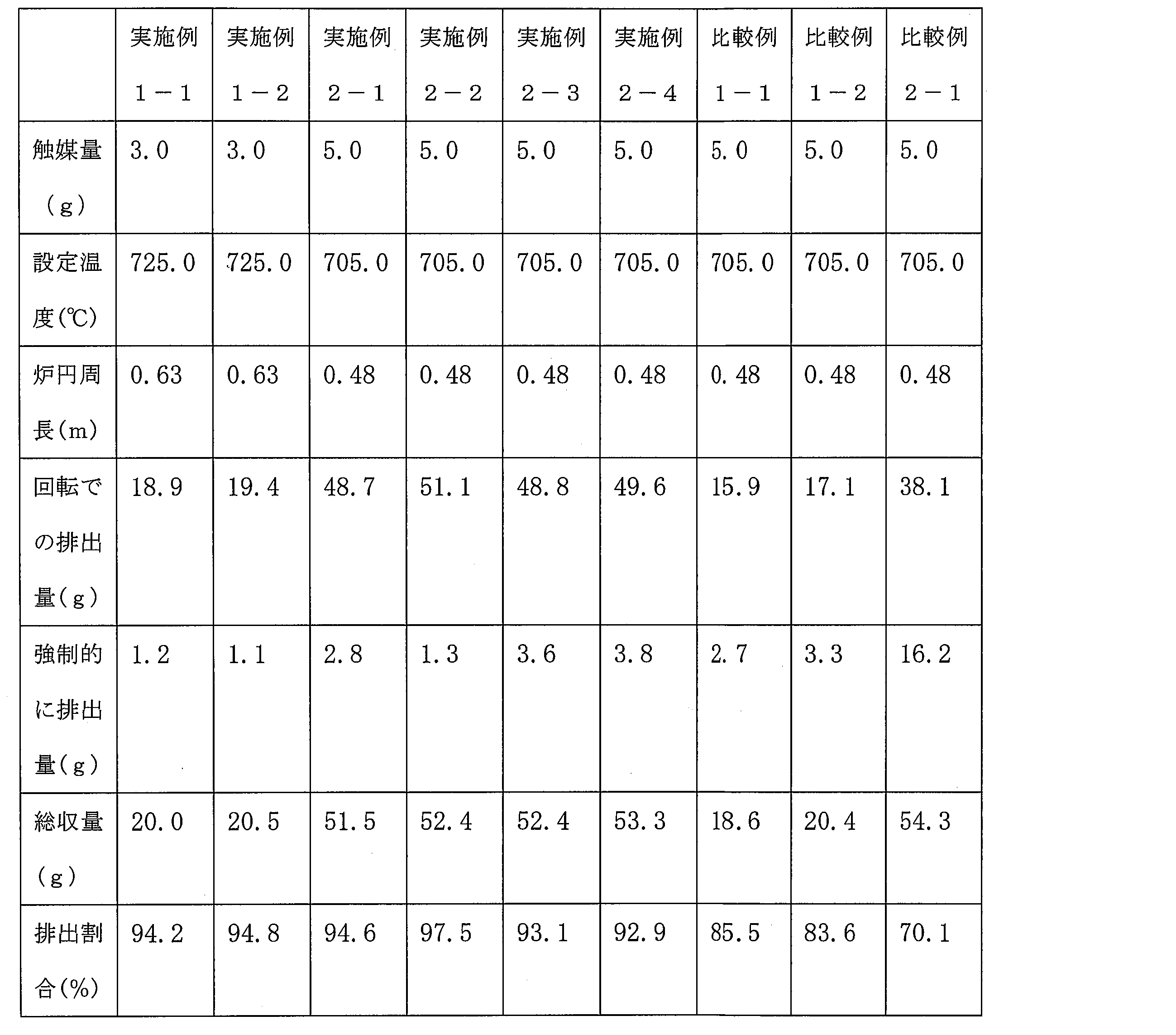
表2に示すように、実施例1-1、2及び実施例2-1~4の触媒粒子を用いた場合、メタン熱分解反応に対して触媒作用した後の触媒粒子のうち90%以上の量をロータリーキルンの回転のみで回収することができた。一方、比較例の触媒粒子1-1、2及び比較例2-1の触媒粒子を用いた場合、70%~86%程度の触媒粒子がロータリーキルンの回転のみで回収することができた。この結果から、崩潰角が30°以下であり、さらにスパチュラ角が58°以下である各実施例の触媒粒子を用いれば、触媒粒子がロータリーキルンの炉壁に付着することを防止できる。
以上から、本発明に係る触媒粒子は、触媒粒子の流動性が高いため、触媒粒子の炉内への付着を低減でき、原料ガスとの接触性を向上できるため、触媒粒子が水素生成反応を効率良く促進できるので、水素の製造効率を向上できて有用である。
Claims (6)
- 炉内で流動されながら加熱される用途で用いられる触媒粒子であって、
崩潰角が30°以下であることを特徴とする触媒粒子。 - スパチュラ角が58°以下であることを特徴とする請求項1に記載の触媒粒子。
- 炉内に崩潰角が30°以下である触媒粒子と、炭化水素を含む原料ガスとを投入するステップと、
前記炉内で前記触媒粒子を流動させながら前記触媒粒子及び原料ガスを加熱するステップと、
前記加熱により発生した水素を回収するステップとを含むことを特徴とする水素の製造方法。 - 前記触媒粒子は、スパチュラ角が58°以下であることを特徴とする請求項3に記載の水素の製造方法。
- 前記炉は、ロータリーキルンであることを特徴とする請求項3又は4に記載の水素の製造方法。
- メタン直接改質(DMR)反応によって水素を発生させることを特徴とする請求項3~5のいずれか1項に記載の水素の製造方法。
Applications Claiming Priority (2)
| Application Number | Priority Date | Filing Date | Title |
|---|---|---|---|
| JP2019-039742 | 2019-03-05 | ||
| JP2019039742A JP6734552B1 (ja) | 2019-03-05 | 2019-03-05 | 触媒粒子及びそれを用いた水素製造方法 |
Publications (1)
| Publication Number | Publication Date |
|---|---|
| WO2020179501A1 true WO2020179501A1 (ja) | 2020-09-10 |
Family
ID=71892309
Family Applications (1)
| Application Number | Title | Priority Date | Filing Date |
|---|---|---|---|
| PCT/JP2020/007070 Ceased WO2020179501A1 (ja) | 2019-03-05 | 2020-02-21 | 触媒粒子及びそれを用いた水素製造方法 |
Country Status (2)
| Country | Link |
|---|---|
| JP (1) | JP6734552B1 (ja) |
| WO (1) | WO2020179501A1 (ja) |
Citations (5)
| Publication number | Priority date | Publication date | Assignee | Title |
|---|---|---|---|---|
| JPS596944A (ja) * | 1982-07-05 | 1984-01-14 | Nippon Kaihatsu Consultant:Kk | 重質油処理用触媒及びその製造法 |
| JP2006516946A (ja) * | 2003-02-05 | 2006-07-13 | ユニベルシテ・ド・リエージュ | カーボンナノチューブの製造方法および製造装置 |
| JP2009221030A (ja) * | 2008-03-13 | 2009-10-01 | Asahi Kasei Chemicals Corp | シリカ成形体 |
| KR20120075760A (ko) * | 2010-12-29 | 2012-07-09 | 제일모직주식회사 | 탄소나노튜브 합성용 담지촉매 및 그 제조방법 |
| WO2016140227A1 (ja) * | 2015-03-04 | 2016-09-09 | 国立大学法人 群馬大学 | カーボンナノチューブ被覆触媒粒子 |
-
2019
- 2019-03-05 JP JP2019039742A patent/JP6734552B1/ja active Active
-
2020
- 2020-02-21 WO PCT/JP2020/007070 patent/WO2020179501A1/ja not_active Ceased
Patent Citations (5)
| Publication number | Priority date | Publication date | Assignee | Title |
|---|---|---|---|---|
| JPS596944A (ja) * | 1982-07-05 | 1984-01-14 | Nippon Kaihatsu Consultant:Kk | 重質油処理用触媒及びその製造法 |
| JP2006516946A (ja) * | 2003-02-05 | 2006-07-13 | ユニベルシテ・ド・リエージュ | カーボンナノチューブの製造方法および製造装置 |
| JP2009221030A (ja) * | 2008-03-13 | 2009-10-01 | Asahi Kasei Chemicals Corp | シリカ成形体 |
| KR20120075760A (ko) * | 2010-12-29 | 2012-07-09 | 제일모직주식회사 | 탄소나노튜브 합성용 담지촉매 및 그 제조방법 |
| WO2016140227A1 (ja) * | 2015-03-04 | 2016-09-09 | 国立大学法人 群馬大学 | カーボンナノチューブ被覆触媒粒子 |
Also Published As
| Publication number | Publication date |
|---|---|
| JP6734552B1 (ja) | 2020-08-05 |
| JP2020142176A (ja) | 2020-09-10 |
Similar Documents
| Publication | Publication Date | Title |
|---|---|---|
| JP2022024997A (ja) | 触媒粒子 | |
| Kharatyan et al. | Coupled SHS reactions as a useful tool for synthesis of materials: An overview | |
| KR102245623B1 (ko) | 신규한 텅스텐 카바이드 분말 및 그의 생산 | |
| JP5604473B2 (ja) | 微細ダイヤモンドの製造方法及び微細ダイヤモンド | |
| RU2513398C2 (ru) | Способы изготовления порошков диборида титана | |
| WO1983004188A1 (fr) | Procede de fabrication de carbures metalliques et leurs precurseurs | |
| AU2006275742B2 (en) | Grinding media and methods associated with the same | |
| Yang et al. | Mechanical-activation-assisted combustion synthesis of SiC | |
| CN104528787A (zh) | 一种制备细粒径氧化铝粉末的方法 | |
| Peddarasi et al. | Mechanochemical effect on synthesis and sintering behavior of MgAl2O4 spinel | |
| JP6923046B2 (ja) | 触媒粒子及びそれを用いた水素製造方法 | |
| WO2020179501A1 (ja) | 触媒粒子及びそれを用いた水素製造方法 | |
| CN105555737A (zh) | 碳化锆的锭及粉末的制造方法 | |
| KR20210018083A (ko) | 탄소나노튜브의 제조방법 및 제조 시스템 | |
| US11713251B2 (en) | Method for preparing powdered composite carbide of tungsten and titanium | |
| KR102289288B1 (ko) | 소입경의 니켈리튬 금속 복합 산화물 분체의 제조 방법 | |
| CN118613567A (zh) | 化学品及碳化物的制造方法 | |
| RU2508249C1 (ru) | Способ получения нанодисперсных порошков карбидов вольфрама и титана методом свс | |
| CN1289391C (zh) | 碳化钨、其制备方法和由其制得的硬质材料 | |
| Mishra et al. | Synthesis of silicon carbide from rice husk in a packed bed arc reactor | |
| JP5323483B2 (ja) | 研磨剤の生成方法及びルチル型二酸化チタンの製造方法におけるこの研磨剤の使用 | |
| US20100158787A1 (en) | Method of Preparing Metal Carbide and Metal Carbide Prepared Using the Same | |
| Chen et al. | Graphene nanosheets‐Inconel 718 nanocomposites fabricated by spark plasma sintering of in‐situ grown vertically standing graphene nanosheets‐Inconel 718 powders | |
| KR100546041B1 (ko) | 로터리 킬른형 노를 사용한 탄화티타늄 분말의 제조방법 | |
| RU2667452C1 (ru) | Способ получения наноразмерного порошка карбида вольфрама |
Legal Events
| Date | Code | Title | Description |
|---|---|---|---|
| 121 | Ep: the epo has been informed by wipo that ep was designated in this application |
Ref document number: 20767125 Country of ref document: EP Kind code of ref document: A1 |
|
| NENP | Non-entry into the national phase |
Ref country code: DE |
|
| 122 | Ep: pct application non-entry in european phase |
Ref document number: 20767125 Country of ref document: EP Kind code of ref document: A1 |