WO2020179475A1 - スラストフォイル軸受 - Google Patents
スラストフォイル軸受 Download PDFInfo
- Publication number
- WO2020179475A1 WO2020179475A1 PCT/JP2020/006801 JP2020006801W WO2020179475A1 WO 2020179475 A1 WO2020179475 A1 WO 2020179475A1 JP 2020006801 W JP2020006801 W JP 2020006801W WO 2020179475 A1 WO2020179475 A1 WO 2020179475A1
- Authority
- WO
- WIPO (PCT)
- Prior art keywords
- bearing
- foil
- leaf
- thrust
- top foil
- Prior art date
- Legal status (The legal status is an assumption and is not a legal conclusion. Google has not performed a legal analysis and makes no representation as to the accuracy of the status listed.)
- Ceased
Links
Images



Classifications
-
- F—MECHANICAL ENGINEERING; LIGHTING; HEATING; WEAPONS; BLASTING
- F01—MACHINES OR ENGINES IN GENERAL; ENGINE PLANTS IN GENERAL; STEAM ENGINES
- F01D—NON-POSITIVE DISPLACEMENT MACHINES OR ENGINES, e.g. STEAM TURBINES
- F01D25/00—Component parts, details, or accessories, not provided for in, or of interest apart from, other groups
- F01D25/16—Arrangement of bearings; Supporting or mounting bearings in casings
- F01D25/166—Sliding contact bearing
- F01D25/168—Sliding contact bearing for axial load mainly
-
- F—MECHANICAL ENGINEERING; LIGHTING; HEATING; WEAPONS; BLASTING
- F16—ENGINEERING ELEMENTS AND UNITS; GENERAL MEASURES FOR PRODUCING AND MAINTAINING EFFECTIVE FUNCTIONING OF MACHINES OR INSTALLATIONS; THERMAL INSULATION IN GENERAL
- F16C—SHAFTS; FLEXIBLE SHAFTS; ELEMENTS OR CRANKSHAFT MECHANISMS; ROTARY BODIES OTHER THAN GEARING ELEMENTS; BEARINGS
- F16C17/00—Sliding-contact bearings for exclusively rotary movement
- F16C17/04—Sliding-contact bearings for exclusively rotary movement for axial load only
- F16C17/042—Sliding-contact bearings for exclusively rotary movement for axial load only with flexible leaves to create hydrodynamic wedge, e.g. axial foil bearings
-
- F—MECHANICAL ENGINEERING; LIGHTING; HEATING; WEAPONS; BLASTING
- F01—MACHINES OR ENGINES IN GENERAL; ENGINE PLANTS IN GENERAL; STEAM ENGINES
- F01D—NON-POSITIVE DISPLACEMENT MACHINES OR ENGINES, e.g. STEAM TURBINES
- F01D25/00—Component parts, details, or accessories, not provided for in, or of interest apart from, other groups
- F01D25/18—Lubricating arrangements
- F01D25/22—Lubricating arrangements using working-fluid or other gaseous fluid as lubricant
-
- F—MECHANICAL ENGINEERING; LIGHTING; HEATING; WEAPONS; BLASTING
- F02—COMBUSTION ENGINES; HOT-GAS OR COMBUSTION-PRODUCT ENGINE PLANTS
- F02C—GAS-TURBINE PLANTS; AIR INTAKES FOR JET-PROPULSION PLANTS; CONTROLLING FUEL SUPPLY IN AIR-BREATHING JET-PROPULSION PLANTS
- F02C7/00—Features, components parts, details or accessories, not provided for in, or of interest apart form groups F02C1/00 - F02C6/00; Air intakes for jet-propulsion plants
- F02C7/06—Arrangements of bearings; Lubricating
-
- F—MECHANICAL ENGINEERING; LIGHTING; HEATING; WEAPONS; BLASTING
- F16—ENGINEERING ELEMENTS AND UNITS; GENERAL MEASURES FOR PRODUCING AND MAINTAINING EFFECTIVE FUNCTIONING OF MACHINES OR INSTALLATIONS; THERMAL INSULATION IN GENERAL
- F16C—SHAFTS; FLEXIBLE SHAFTS; ELEMENTS OR CRANKSHAFT MECHANISMS; ROTARY BODIES OTHER THAN GEARING ELEMENTS; BEARINGS
- F16C17/00—Sliding-contact bearings for exclusively rotary movement
- F16C17/10—Sliding-contact bearings for exclusively rotary movement for both radial and axial load
-
- F—MECHANICAL ENGINEERING; LIGHTING; HEATING; WEAPONS; BLASTING
- F16—ENGINEERING ELEMENTS AND UNITS; GENERAL MEASURES FOR PRODUCING AND MAINTAINING EFFECTIVE FUNCTIONING OF MACHINES OR INSTALLATIONS; THERMAL INSULATION IN GENERAL
- F16C—SHAFTS; FLEXIBLE SHAFTS; ELEMENTS OR CRANKSHAFT MECHANISMS; ROTARY BODIES OTHER THAN GEARING ELEMENTS; BEARINGS
- F16C27/00—Elastic or yielding bearings or bearing supports, for exclusively rotary movement
- F16C27/02—Sliding-contact bearings
-
- F—MECHANICAL ENGINEERING; LIGHTING; HEATING; WEAPONS; BLASTING
- F05—INDEXING SCHEMES RELATING TO ENGINES OR PUMPS IN VARIOUS SUBCLASSES OF CLASSES F01-F04
- F05D—INDEXING SCHEME FOR ASPECTS RELATING TO NON-POSITIVE-DISPLACEMENT MACHINES OR ENGINES, GAS-TURBINES OR JET-PROPULSION PLANTS
- F05D2220/00—Application
- F05D2220/30—Application in turbines
-
- F—MECHANICAL ENGINEERING; LIGHTING; HEATING; WEAPONS; BLASTING
- F05—INDEXING SCHEMES RELATING TO ENGINES OR PUMPS IN VARIOUS SUBCLASSES OF CLASSES F01-F04
- F05D—INDEXING SCHEME FOR ASPECTS RELATING TO NON-POSITIVE-DISPLACEMENT MACHINES OR ENGINES, GAS-TURBINES OR JET-PROPULSION PLANTS
- F05D2220/00—Application
- F05D2220/40—Application in turbochargers
-
- F—MECHANICAL ENGINEERING; LIGHTING; HEATING; WEAPONS; BLASTING
- F05—INDEXING SCHEMES RELATING TO ENGINES OR PUMPS IN VARIOUS SUBCLASSES OF CLASSES F01-F04
- F05D—INDEXING SCHEME FOR ASPECTS RELATING TO NON-POSITIVE-DISPLACEMENT MACHINES OR ENGINES, GAS-TURBINES OR JET-PROPULSION PLANTS
- F05D2240/00—Components
- F05D2240/50—Bearings
- F05D2240/52—Axial thrust bearings
-
- F—MECHANICAL ENGINEERING; LIGHTING; HEATING; WEAPONS; BLASTING
- F16—ENGINEERING ELEMENTS AND UNITS; GENERAL MEASURES FOR PRODUCING AND MAINTAINING EFFECTIVE FUNCTIONING OF MACHINES OR INSTALLATIONS; THERMAL INSULATION IN GENERAL
- F16C—SHAFTS; FLEXIBLE SHAFTS; ELEMENTS OR CRANKSHAFT MECHANISMS; ROTARY BODIES OTHER THAN GEARING ELEMENTS; BEARINGS
- F16C2206/00—Materials with ceramics, cermets, hard carbon or similar non-metallic hard materials as main constituents
- F16C2206/02—Carbon based material
-
- F—MECHANICAL ENGINEERING; LIGHTING; HEATING; WEAPONS; BLASTING
- F16—ENGINEERING ELEMENTS AND UNITS; GENERAL MEASURES FOR PRODUCING AND MAINTAINING EFFECTIVE FUNCTIONING OF MACHINES OR INSTALLATIONS; THERMAL INSULATION IN GENERAL
- F16C—SHAFTS; FLEXIBLE SHAFTS; ELEMENTS OR CRANKSHAFT MECHANISMS; ROTARY BODIES OTHER THAN GEARING ELEMENTS; BEARINGS
- F16C2240/00—Specified values or numerical ranges of parameters; Relations between them
- F16C2240/40—Linear dimensions, e.g. length, radius, thickness, gap
-
- F—MECHANICAL ENGINEERING; LIGHTING; HEATING; WEAPONS; BLASTING
- F16—ENGINEERING ELEMENTS AND UNITS; GENERAL MEASURES FOR PRODUCING AND MAINTAINING EFFECTIVE FUNCTIONING OF MACHINES OR INSTALLATIONS; THERMAL INSULATION IN GENERAL
- F16C—SHAFTS; FLEXIBLE SHAFTS; ELEMENTS OR CRANKSHAFT MECHANISMS; ROTARY BODIES OTHER THAN GEARING ELEMENTS; BEARINGS
- F16C2360/00—Engines or pumps
- F16C2360/23—Gas turbine engines
-
- F—MECHANICAL ENGINEERING; LIGHTING; HEATING; WEAPONS; BLASTING
- F16—ENGINEERING ELEMENTS AND UNITS; GENERAL MEASURES FOR PRODUCING AND MAINTAINING EFFECTIVE FUNCTIONING OF MACHINES OR INSTALLATIONS; THERMAL INSULATION IN GENERAL
- F16C—SHAFTS; FLEXIBLE SHAFTS; ELEMENTS OR CRANKSHAFT MECHANISMS; ROTARY BODIES OTHER THAN GEARING ELEMENTS; BEARINGS
- F16C2360/00—Engines or pumps
- F16C2360/23—Gas turbine engines
- F16C2360/24—Turbochargers
Definitions
- the present invention relates to a thrust foil bearing.
- the spindle of a turbomachine (for example, a gas turbine or turbocharger) is rotationally driven at high speed. Also, the turbine blades attached to the spindle are exposed to high temperatures. Therefore, bearings that support these spindles are required to withstand harsh environments such as high temperature and high speed rotation.
- a bearing for this type of application an oil-lubricated rolling bearing or an oil dynamic pressure bearing may be used, but when lubrication with a liquid such as lubricating oil is difficult, from the viewpoint of energy efficiency, a lubricating oil circulation system accessory
- the use of these bearings is restricted under conditions such as when it is difficult to provide a separate bearing, or when resistance due to liquid shearing becomes a problem. Therefore, pneumatic bearings are attracting attention as bearings suitable for use under such conditions.
- a bearing surface on both the rotating side and the fixed side is generally composed of a rigid body.
- whirl when the stability limit is exceeded. Whirling of the spindle is likely to occur. Therefore, it is important to manage the gap according to the rotation speed used.
- the width of the radial bearing gap fluctuates due to the effect of thermal expansion, so accurate gap management becomes extremely difficult.
- Foil bearings are known as bearings that are less likely to cause whirl and can easily manage gaps even in an environment with large temperature changes.
- the foil bearing has a bearing surface formed of a thin film (foil) having low rigidity with respect to bending, and supports the load by allowing the bearing surface to bend.
- the inner peripheral surface of the bearing is composed of a thin plate called the top foil, and a spring-like member called the back foil is placed on the outer diameter side of the bearing to elastically support the load received by the top foil with the back foil. There is.
- an air film is formed between the outer peripheral surface of the shaft and the inner peripheral surface of the top foil, and the shaft is non-contact supported.
- Foil bearings are generally characterized by excellent stability because the flexibility of the foil forms an appropriate radial bearing gap according to operating conditions such as shaft rotation speed, load, and ambient temperature. It can be used at higher speeds than pneumatic bearings. Further, it is necessary to manage the radial bearing gap of a general dynamic bearing on the order of 1/1000 of the shaft diameter. For example, for a shaft having a diameter of several mm, it is necessary to always secure a radial bearing gap of about several ⁇ m. .. Therefore, strict clearance control is difficult in consideration of manufacturing tolerances and thermal expansion when the temperature changes drastically. On the other hand, in the case of a foil bearing, it is sufficient to manage the radial bearing gap of about several tens of ⁇ m, which has an advantage that the manufacturing and the gap management become easy.
- Patent Document 1 one that elastically supports the top foil by cutting and raising provided on the back foil
- Patent Document 2 one that elastically supports the bearing foil by an elastic body formed by braiding the strands
- Patent Document 3 a back foil provided with a support portion that contacts the inner surface of the outer ring and does not move in the circumferential direction and an elastic portion that elastically bends due to the surface pressure from the top foil
- the top foil is divided in the circumferential direction to form a leaf foil without providing the back foil, and the leaf foils are provided at a plurality of positions in the circumferential direction while partially overlapping the leaf foils.
- the leaf foils are provided at a plurality of positions in the circumferential direction while partially overlapping the leaf foils.
- the fixed bearing ring is divided into a plurality of arcuate ring members in the circumferential direction, one end of the foil is welded to the joint end of each arcuate ring member, and a Rayleigh step is bent on the foil.
- Patent Document 4 those in which the leaves are formed of piezo bimorph (Patent Document 5), those in which the leaf foil is formed of bimetal composed of two kinds of metals having different linear expansion coefficients (Patent Document 6), etc. It is known.
- the present invention is a thrust foil bearing in which a bearing surface is formed by arranging a plurality of leaves in the circumferential direction, and the leaf has a top foil portion forming the bearing surface. Then, the circumferential length of the top foil portion per leaf at the radial center position of the top foil portion with respect to the radial length from the inner diameter side edge portion to the outer diameter side edge portion of the top foil portion. It is characterized in that the height ratio is set to 0.66 or less.
- a predetermined number or more of leaves are arranged in the circumferential direction of the bearing.
- the load capacity of the bearing can be secured above a certain level.
- the length ratio can be 0.55 or more.
- the bearing can be configured with the minimum number of leaves that can secure the load capacity of the bearing above a predetermined level, the load capacity of the bearing can be secured above a certain level, the manufacturing cost of the bearing can be suppressed as much as possible, and the reliability of the product performance can be secured. Can be further improved.
- the load capacity of the bearing can be secured above a certain level.
- FIG. 5 is a developed view of a cross section taken along line XX in FIG. 4. It is a figure which shows the result of having experimented the relationship of the load capacity coefficient of a bearing with respect to a leaf aspect ratio.
- FIG. 1 conceptually shows the configuration of a gas turbine, which is a type of turbomachine.
- the gas turbine mainly includes a turbine 1 and a compressor 2, each of which has a blade row, a generator 3, a combustor 4, and a regenerator 5.
- the turbine 1, the compressor 2, and the generator 3 are provided with a common rotating shaft 6 extending in the horizontal direction, and the rotating shaft 6 and the turbine 1 and the compressor 2 form an integrally rotatable rotor. ..
- the air sucked from the intake port 7 is compressed by the compressor 2, heated by the regenerator 5, and then sent to the combustor 4.
- Fuel is mixed with this compressed air and burned, and the turbine 1 is rotated by a high-temperature, high-pressure gas.
- the rotational force of the turbine 1 is transmitted to the generator 3 via the rotating shaft 6, and the generator 3 rotates to generate electric power, which is output via the inverter 8. Since the gas after rotating the turbine 1 is at a relatively high temperature, this gas is sent to the regenerator 5 to exchange heat with the compressed air before combustion, so that the heat of the gas after combustion is regenerated. To use.
- the gas that has completed heat exchange in the regenerator 5 is discharged as exhaust gas after passing through the exhaust heat recovery device 9.
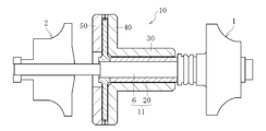
- FIG. 2 shows a foil bearing unit 10 that supports the rotating shaft 6 of the rotor in the gas turbine.
- the foil bearing unit 10 includes a rotating shaft 6, a rotating member 20 fixed to the rotating shaft 6, a radial foil bearing 30, a first thrust foil bearing 40, and a second thrust foil bearing 50.
- the shaft member 11 is composed of the rotating shaft 6 and the rotating member 20 that rotate integrally.
- the radial foil bearing 30 supports the shaft member 11 in the radial direction, and the first thrust foil bearing 40 and the second thrust foil bearing 50 support the shaft member 11 in both thrust directions.
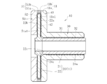
- the rotating member 20 includes a sleeve portion 21 and a disk-shaped flange portion 22 protruding from the sleeve portion 21 to an outer diameter.
- the flange portion 22 is formed of, for example, a carbon fiber reinforced composite material
- the sleeve portion 21 is formed of, for example, a carbon sintered material.
- the configuration of the first thrust foil bearing 40 will be described. Since the configuration of the second thrust bearing 50 is the same as that of the first thrust bearing 40, the description thereof will be omitted.
- the first thrust foil bearing 40 supports the flange portion 22 of the shaft member 11 (rotating member 20) from one side in the axial direction, and as shown in FIGS. 3 and 4, the foil.
- the holder 41 and a plurality of leaves 42 attached to the foil holder 41 so as to form a strip in the circumferential direction are provided.
- the foil holder 41 has a disk-shaped holder main body 41a having a hole in the axial center, and an annular fixing member 41b provided at the outer diameter end of the end surface 41a1 of the holder main body 41a.
- the leaf 42 is formed of a metal having a high spring property and good workability, for example, a leaf material having a thickness of about 20 ⁇ m to 200 ⁇ m made of a steel material or a copper alloy.
- a leaf material it is preferable to use a material made of stainless steel or bronze.
- each leaf 42 has a main body portion 42a constituting a top foil portion Tf and a back foil portion Bf, which will be described later, and an extending portion 42b extending from the main body portion 42a to the outer diameter side (indicated by cross hatching). And are integrated.
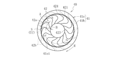
- the main body portion 42a of the leaf 42 has a front end 421 located at an end portion on the rotation direction R side, a rear end 422 located at an end portion on the opposite rotation direction side, and an inner diameter side edge portion 423 connected to both side ends of the front end 421. And an outer diameter side edge portion 424 (which is also an inner diameter side edge portion and an outer diameter side edge portion of the top foil portion). Both the inner diameter side edge portion 423 and the outer diameter side edge portion 424 of each leaf 42 are formed by an arc centered on the axis.
- the front end 421 and the rear end 422 have a so-called herringbone shape, the front end 421 is formed in a convex shape in which a region between both end portions thereof is projected in the rotation direction R side, and the rear end 422 is formed at both end portions thereof. It is formed in a concave shape with a recess in the R side in the rotation direction.
- the front end 421 and the rear end 422 have tops 421a, 422a in a roughly central region in the radial direction.
- the front end 421 and the rear end 422 in the herringbone shape in this manner, it is possible to obtain the action of drawing the fluid (for example, air) into the radial center region of the thrust bearing gap during the rotation of the shaft member 11, and thus the thrust can be obtained. It is possible to increase the load capacity of the foil bearing.
- the contour shapes of both tops 421a and 422a are circular is illustrated.
- the extending portion 42b is formed so as to extend in an inclined direction with respect to the radial direction by retracting the outer diameter side in the counter-rotational direction from the outer diameter end of the main body portion 42a.
- the extending portions 42b arranged in the rotation direction R are arranged on the same plane of the holder main body 41a via a gap in the rotation direction R without overlapping each other.
- the fixing member 41b is arranged on each extending portion 42b arranged on the holder main body 41a, and the outer diameter portion (shown by cross hatching in FIG. 5) of the extending portion 42b of each leaf 42 is attached to the holder main body 41a and the fixing member 41b.
- Each leaf 42 is fixed to the foil holder 41 by sandwiching the members 41a and 41b with and fixing the members 41a and 41b with bolts or the like.
- FIG. 6 is a cross-sectional view of line XX in FIG.
- the leaves 42 of the first thrust foil bearing 40 are partially overlapped with each other in the rotational direction R on the end surface 41a1 of the holder body 41a while shifting the phase by a half pitch of each leaf 42. It is arranged.
- the region on the front side in the rotation direction including the front end 421 of each leaf 42 constitutes a top foil portion Tf that rides on the adjacent leaf 42.
- the region on the side opposite to the rotation direction including the rear end 422 of each leaf 42 constitutes a back foil portion Bf that elastically supports the top foil portion Tf behind the top foil portion Tf of the adjacent leaf 42.
- a thrust bearing surface S facing one end surface 22a of the flange portion 22 is formed on the surface of the top foil portion Tf of each leaf 42.
- the front side of the top foil portion Tf of each leaf 42 in the rotation direction is the portion closest to the flange portion 22 and the bearing gap is minimized.
- the circumferential length of the top foil portion Tf at the radial center position of the top foil portion Tf (in other words, the top 421a of the leaf 42 and the top 421a of the leaf 42 adjacent to the leaf 42.
- the distance in the circumferential direction is A, and the radial length from the inner diameter side edge 423 of the top foil portion Tf to the outer diameter side edge 424 (in other words, from the inner diameter side edge 423 of the leaf 42 to the fixing member 41b).
- the leaf aspect ratio is set to about 0.6, where the length A to the inner diameter is the length B and the ratio of the length A to the length B is the leaf aspect ratio.
- the length A is the average value of the inner diameter of the fixing member 41b and the diameter of the inner circle formed by the inner diameter side edge portion 423 of each leaf 42 multiplied by ⁇ , and the leaf 42 provided on the foil bearing 40. It can be obtained as a value divided by the number of sheets.
- the length A becomes smaller as the number of the leaves 42 in the circumferential direction increases, that is, as the length of the part of the top foil portion Tf per leaf 42 becomes shorter.
- the smaller the length A the smaller the leaf aspect ratio, and the larger the number of leaves 42 constituting the foil bearing 40.
- the increase in the number of leaves 42 increases cost and variations in bearing performance.
- the leaf aspect ratio to approximately 0.6, it is possible to set the minimum number of leaves 42 that can secure a certain amount of load capacity (details will be described later).
- the thrust foil bearing 40 As a method of manufacturing the thrust foil bearing 40, one foil bearing in which half of the leaves 42 arranged in the circumferential direction of the thrust foil bearing 40 are arranged at equal intervals in the circumferential direction, more specifically, the foil bearing is used. One foil bearing and the other foil bearing in which each of the 40 leaves 42 is arranged every other are prepared. Then, in a state where the leaf 42 of one foil bearing and the leaf 42 of the other foil bearing are displaced in the circumferential direction by a half pitch of the leaf 42, one foil bearing and the other foil bearing are overlapped. In this state, the leaf 42 is fixed to the foil holder 41 by sandwiching the holder main body 41a and the fixing member 41b and tightening and fixing both members 41a and 41b with bolts or the like. Thereby, the thrust foil bearing 40 can be manufactured.
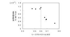
- FIG. 7 shows an experimental result regarding the relationship between the leaf aspect ratio and the load capacity coefficient of the foil bearing 40.
- the load capacity coefficient [N / (mm) 3 krpm] is the maximum load capacity of the foil bearing 40 is N MAX [N], and the radial length between the inner diameter side edge portion 423 and the outer diameter side edge portion 424.
- the larger the leaf aspect ratio that is, the smaller the number of leaves, the smaller the load capacity coefficient.
- the leaf aspect ratio is 0.6
- the load capacity coefficient becomes smaller. Is greatly reduced.
- the leaf aspect ratio is 0.7 or more
- the load capacitance coefficient is far below 1.0.
- the leaf aspect ratio is 0.66 or less
- the value of the load capacity coefficient is a certain value or more, and particularly when the leaf aspect ratio is 0.6 or less, there is no great difference in the load capacity coefficient, and a value of 1.0 or more is recorded. There is.
- the leaf aspect ratio when the leaf aspect ratio is 0.66 or less, particularly 0.6 or less, a sufficiently large load capacity coefficient can be secured. Further, as described above, considering that it is preferable to reduce the number of leaves as much as possible in terms of cost and reliability of the bearing, the leaf aspect ratio becomes more preferable as it approaches 0.6. More specifically, considering the cost and the reliability of the bearing, it is preferable that the leaf aspect ratio is 0.55 or more. Further, by setting the leaf aspect ratio to approximately 0.6 as in the above-described embodiment, the size of the load capacity can be secured and the number of leaves can be minimized, which is the most preferable.
- the present invention is not limited to the above-described embodiments, and it goes without saying that various modifications can be made without departing from the gist of the present invention.
- the shape of the bearing is an example, and it goes without saying that the shape is not limited to that shape.
Landscapes
- Engineering & Computer Science (AREA)
- General Engineering & Computer Science (AREA)
- Mechanical Engineering (AREA)
- Chemical & Material Sciences (AREA)
- Combustion & Propulsion (AREA)
- Physics & Mathematics (AREA)
- Fluid Mechanics (AREA)
- Support Of The Bearing (AREA)
- Sliding-Contact Bearings (AREA)
Abstract
複数のリーフ42を円周方向に並べることでスラスト軸受面Sが形成されるスラストフォイル軸受40であって、リーフ42は、スラスト軸受面Sを形成するトップフォイル部Tfを有し、トップフォイル部Tfの内径側縁部423から外径側縁部424までの径方向長さBに対する、トップフォイル部Tfの径方向中央位置における、リーフ42の1枚当たりの当該トップフォイル部Tfの周方向長さAの比を0.66以下とすることを特徴とする。
Description
本発明は、スラストフォイル軸受に関する。
ターボ機械(例えばガスタービンやターボチャージャ)の主軸は高速で回転駆動される。また、主軸に取り付けられたタービン翼は高温に晒される。そのため、これらの主軸を支持する軸受には、高温・高速回転といった過酷な環境に耐え得ることが要求される。この種の用途の軸受として、油潤滑の転がり軸受や油動圧軸受を使用する場合もあるが、潤滑油などの液体による潤滑が困難な場合、エネルギー効率の観点から潤滑油循環系の補機を別途設けることが困難な場合、あるいは液体のせん断による抵抗が問題になる場合、等の条件下では、これらの軸受の使用は制約を受ける。そこで、そのような条件下での使用に適合する軸受として、空気動圧軸受が着目されている。
空気動圧軸受としては、回転側と固定側の双方の軸受面を剛体で構成したものが一般的である。しかしながら、この種の空気動圧軸受では、回転側と固定側の軸受面間に形成されるラジアル軸受隙間の管理が不十分であると、安定限界を超えた際にホワールと呼ばれる自励的な主軸の振れ回りを生じ易い。そのため、使用される回転速度に応じた隙間管理が重要となる。特に、ガスタービンやターボチャージャのように、温度変化の激しい環境では熱膨張の影響でラジアル軸受隙間の幅が変動するため、精度の良い隙間管理は極めて困難となる。
ホワールが生じにくく、かつ温度変化の大きい環境下でも隙間管理を容易にできる軸受としてフォイル軸受が知られている。フォイル軸受は、曲げに対して剛性の低い可撓性を有する薄膜(フォイル)で軸受面を構成し、軸受面のたわみを許容することで荷重を支持するものである。通常は、軸受の内周面をトップフォイルと呼ばれる薄板で構成し、その外径側にバックフォイルと呼ばれるばね状の部材を配置してトップフォイルが受ける荷重をバックフォイルで弾性的に支持している。この場合、軸の回転時には、軸の外周面とトップフォイルの内周面との間に空気膜が形成され、軸が非接触支持される。
フォイル軸受では、フォイルの可撓性により、軸の回転速度や荷重、周囲温度等の運転条件に応じた適切なラジアル軸受隙間が形成されるため、安定性に優れるという特徴があり、一般的な空気動圧軸受と比較して高速での使用が可能である。また、一般的な動圧軸受のラジアル軸受隙間は軸直径の1/1000のオーダーで管理する必要があり、例えば直径数mm程度の軸では数μm程度のラジアル軸受隙間を常時確保する必要がある。従って、製造時の公差、さらには温度変化が激しい場合の熱膨張まで考慮すると、厳密な隙間管理は困難である。これに対して、フォイル軸受の場合には、数十μm程度のラジアル軸受隙間に管理すれば足り、その製造や隙間管理が容易となる利点を有する。
フォイル軸受としては、バックフォイルに設けた切り起こしでトップフォイルを弾性的に支持するもの(特許文献1)、素線を網状に編成した弾性体で軸受フォイルを弾性的に支持するもの(特許文献2)、および、バックフォイルに、外輪内面に接触し周方向に移動しない支持部とトップフォイルからの面圧により弾性的に撓む弾性部とを設けたもの(特許文献3)等が公知である。
フォイル軸受の一種として、バックフォイルを設けず、トップフォイルを周方向で分割してリーフフォイルを形成し、リーフフォイルをその一部を重ね合わせながら周方向の複数個所に設け、リーフフォイルの重なり合った部分でばね性を得るリーフ型と呼ばれるものも存在する。このリーフ型のフォイル軸受としては、固定軸受環を周方向で複数の円弧状環部材に分割し、各円弧状環部材の接合端部にフォイルの一端を溶接すると共に、フォイルにレイリーステップを屈曲形成したもの(特許文献4)、リーフをピエゾバイモルフで形成したもの(特許文献5)、リーフフォイルを線膨張率の異なる2種類の金属からなるバイメタルにより形成したもの(特許文献6)、等が公知である。
上記のリーフフォイルを有する軸受では、軸受性能として、所定以上の軸受の負荷容量を確保することが課題になる。
上記の課題を解決するため、本発明は、複数のリーフを円周方向に並べることで軸受面が形成されるスラストフォイル軸受であって、前記リーフは、軸受面を形成するトップフォイル部を有し、前記トップフォイル部の内径側縁部から外径側縁部までの径方向長さに対する、前記トップフォイル部の径方向中央位置における、前記リーフ1枚あたりの前記トップフォイル部の周方向長さの比を0.66以下とすることを特徴とする。
本発明のように、リーフ1枚当たりの径方向長さに対するトップフォイル部の周方向長さの比を0.66以下に規定することで、軸受の周方向に所定の枚数以上のリーフを配置することができ、軸受の負荷容量を一定以上確保することができる。
上記のスラストフォイル軸受として、トップフォイル部の内径側縁部から外径側縁部までの径方向長さに対する、トップフォイル部の径方向中央位置における、リーフ1枚あたりのトップフォイル部の周方向長さの比を0.55以上とすることができる。これにより、リーフの枚数を所定以下の枚数にすることができ、一定以上の軸受の負荷容量を確保すると共に、軸受の製造コストを抑え、製品性能の信頼性を向上させることができる。
上記のスラストフォイル軸受として、トップフォイル部の内径側縁部から外径側縁部までの径方向長さに対する、トップフォイル部の径方向中央位置における、リーフ1枚あたりのトップフォイル部の周方向長さの比を0.6とすることができる。これにより、所定以上の軸受の負荷容量を確保できる最小枚数のリーフで軸受を構成することができ、軸受の負荷容量を一定以上確保すると共に、軸受の製造コストを極力抑え、製品性能の信頼性をより向上させることができる。
本発明のスラストフォイル軸受によれば、軸受の負荷容量を一定以上確保することができる。
以下、本発明に係る実施の形態について、図面を参照して説明する。
図1に、ターボ機械の一種であるガスタービンの構成を概念的に示す。このガスタービンは、それぞれに翼列を形成したタービン1および圧縮機2と、発電機3と、燃焼器4と、再生器5とを主に備える。タービン1、圧縮機2、および発電機3には、水平方向に延びる共通の回転軸6が設けられ、この回転軸6と、タービン1および圧縮機2とで一体回転可能のロータが構成される。
図1に、ターボ機械の一種であるガスタービンの構成を概念的に示す。このガスタービンは、それぞれに翼列を形成したタービン1および圧縮機2と、発電機3と、燃焼器4と、再生器5とを主に備える。タービン1、圧縮機2、および発電機3には、水平方向に延びる共通の回転軸6が設けられ、この回転軸6と、タービン1および圧縮機2とで一体回転可能のロータが構成される。
吸気口7から吸入された空気は、圧縮機2で圧縮され、再生器5で加熱された上で燃焼器4に送り込まれる。この圧縮空気に燃料を混合して燃焼させ、高温、高圧のガスでタービン1を回転させる。タービン1の回転力が回転軸6を介して発電機3に伝達され、発電機3が回転することにより発電し、この電力がインバータ8を介して出力される。タービン1を回転させた後のガスは比較的高温であるため、このガスを再生器5に送り込んで燃焼前の圧縮空気との間で熱交換を行うことで、燃焼後のガスの熱を再利用する。再生器5で熱交換を終えたガスは、排熱回収装置9を通ってから排ガスとして排出される。
図2に、上記ガスタービンにおけるロータの回転軸6を支持するフォイル軸受ユニット10を示す。フォイル軸受ユニット10は、回転軸6と、回転軸6に固定された回転部材20と、ラジアルフォイル軸受30と、第1スラストフォイル軸受40と、第2スラストフォイル軸受50とを備える。一体に回転する回転軸6と回転部材20とで軸部材11が構成される。ラジアルフォイル軸受30は軸部材11をラジアル方向で支持し、第1スラストフォイル軸受40および第2スラストフォイル軸受50は、軸部材11を両スラスト方向で支持する。
回転部材20は、図3に示すように、スリーブ部21と、スリーブ部21から外径に突出した円盤状のフランジ部22とを備える。フランジ部22は例えば炭素繊維強化複合材で形成され、スリーブ部21は例えば炭素焼結材で形成される。
以下、第1スラストフォイル軸受40の構成を説明する。なお、第2スラスト軸受50の構成は、第1スラスト軸受40と共通するので、その説明を省略する。
第1スラストフォイル軸受40は、図3に示すように、軸部材11(回転部材20)のフランジ部22を軸方向一方側から支持するものであり、図3および図4に示すように、フォイルホルダ41と、フォイルホルダ41に、周方向で帯状となるように取り付けられる複数のリーフ42とを備える。フォイルホルダ41は、軸心に穴を有する円盤状のホルダ本体41aと、ホルダ本体41aの端面41a1の外径端に設けられた環状の固定部材41bとを有する。ホルダ本体41aと固定部材41bで各リーフ42を軸方向両側から挟み込むことにより、各リーフ42がフォイルホルダ41に保持される。
リーフ42は、ばね性に富み、かつ、加工性のよい金属、例えば鋼材料や銅合金からなる厚さ20μm~200μm程度のリーフ素材で形成される。リーフ素材としては、ステンレス鋼もしくは青銅製からなるものを用いるのが好ましい。
図4に示すように、リーフ42は回転方向R(円周方向)の複数個所に等ピッチで配置される。図5は、回転方向Rに並べた複数のリーフ42のうち、一つのリーフ42のみを図示して他のリーフの図示を省略したものである。図5に示すように、各リーフ42は、後述するトップフォイル部Tfおよびバックフォイル部Bfを構成する本体部42aと、本体部42aから外径側に延びる延在部42b(クロスハッチングで示す)とを一体に備える。
リーフ42の本体部42aは、回転方向R側の端部に位置する前端421と、反回転方向側の端部に位置する後端422と、前端421の両側端につながった内径側縁部423および外径側縁部424(トップフォイル部の内径側縁部および外径側縁部でもある)とを有する。各リーフ42の内径側縁部423および外径側縁部424の双方が軸心を中心とする円弧で形成されている。前端421および後端422は、いわゆるヘリングボーン形状をなしており、前端421はその両端部の間の領域を回転方向R側に突出させた凸形状に形成され、後端422は、その両端部の間を回転方向R側に凹ませた凹形状に形成されている。前端421および後端422は、半径方向の概ね中央領域に頂部421a,422aを有する。このように前端421および後端422をヘリングボーン形状に形成することにより、軸部材11の回転中に流体(例えば空気)をスラスト軸受隙間の半径方向中央領域に引き込む作用を得ることができ、スラストフォイル軸受の負荷容量を高めることが可能となる。本実施形態では、双方の頂部421a,422aの輪郭形状を円弧にした場合を例示している。
延在部42bは、本体部42aの外径端から、外径側を反回転方向に後退させることで半径方向に対して傾斜方向に延びるように形成されている。図4に示すように、回転方向Rに配列された各延在部42bは、互いに重なり合うことなく回転方向Rの隙間を介してホルダ本体41aの同一平面上に配置される。ホルダ本体41a上に並べた各延在部42b上に固定部材41bを配置し、各リーフ42の延在部42bの外径部分(図5にクロスハッチングで示す)をホルダ本体41aと固定部材41bとで挟み込み、両部材41a,41bをボルト等で締め付け固定することで、各リーフ42がフォイルホルダ41に固定される。
図6は、図4中のX-X線の断面図である。図6に示すように、第1スラストフォイル軸受40の各リーフ42は、ホルダ本体41aの端面41a1上に、各リーフ42の半ピッチ分だけ位相をずらしながら回転方向Rに部分的に重ね合わせて配置されている。各リーフ42の前端421を含む回転方向先行側の領域は、隣接するリーフ42上に乗り上げたトップフォイル部Tfを構成する。また、各リーフ42の後端422を含む反回転方向側の領域は、隣接するリーフ42のトップフォイル部Tfの背後で当該トップフォイル部Tfを弾性的に支持するバックフォイル部Bfを構成する。各リーフ42のトップフォイル部Tfの表面で、フランジ部22の一方の端面22aと対向するスラスト軸受面Sが形成される。各リーフ42のトップフォイル部Tfの回転方向先行側が、フランジ部22に最も近づき、軸受隙間が最小となる部分である。
図4に示すように、トップフォイル部Tfの径方向中央位置におけるトップフォイル部Tfの周方向長さ(言い換えると、リーフ42の頂部421aと、このリーフ42に隣接するリーフ42の頂部421aとの周方向の間隔)を長さA、トップフォイル部Tfの内径側縁部423から外径側縁部424までの径方向長さ(言い換えると、リーフ42の内径側縁部423から固定部材41bの内径までの径方向長さ)を長さBとし、長さBに対する長さAの比をリーフアスペクト比とすると、本実施形態では、このリーフアスペクト比を略0.6に設定している。なお、長さAは固定部材41bの内径と各リーフ42の内径側縁部423によって形成される内円の直径との平均値にπをかけたものを、フォイル軸受40に設けられたリーフ42の枚数で割った値として求めることができる。
リーフ42の周方向の枚数が多くなるほど、つまり、リーフ42の1枚当たりのトップフォイル部Tfを構成する部分の長さが短くなるほど、長さAは小さくなる。言い換えると、長さAが小さくなるほど上記のリーフアスペクト比が小さくなり、フォイル軸受40を構成するリーフ42の枚数は多くなる。リーフ42の枚数は多くなるほどフォイル軸受40の最大負荷容量が大きくなるが、一方で、リーフ42の枚数増加によるコストアップや軸受性能のバラツキが大きくなってしまう。
本実施形態では、リーフアスペクト比を略0.6に設定することで、一定以上の負荷容量の大きさを確保できる最小限のリーフ42の枚数に設定することができる(詳しくは後述する)。
上記のスラストフォイル軸受40の製造方法としては、スラストフォイル軸受40の周方向に配置されたリーフ42の半数のリーフ42を周方向に等間隔に並べた一方のフォイル軸受、より詳しくは、フォイル軸受40の各リーフ42を一つ置きに並べた一方のフォイル軸受と他方のフォイル軸受とを用意する。そして、一方のフォイル軸受のリーフ42と他方のフォイル軸受のリーフ42とがリーフ42の半ピッチ分だけ周方向にずらした状態で、一方のフォイル軸受と他方のフォイル軸受を重ね合わせる。この状態で、ホルダ本体41aと固定部材41bとで挟み込み、両部材41a,41bをボルト等で締め付け固定することで、各リーフ42がフォイルホルダ41に固定する。これにより、スラストフォイル軸受40を製造することができる。
次に、上記のリーフアスペクト比とフォイル軸受40の負荷容量係数との関係についての実験結果を図7に示す。この実験は、軸受面の径方向長さ(つまり長さB)を変更させずに、リーフの枚数(つまり長さA)を変化させて、その時の負荷容量係数の変化を測定したものである。なお、負荷容量係数〔N/(mm)3krpm〕は、フォイル軸受40の最大負荷容量をNMAX〔N〕、内径側縁部423と外径側縁部424との間の径方向長さ(上記の長さBと同じ)をLa[mm]、内径側縁部423の径と外径側縁部424の径との平均値をLb[mm]、軸部材11の回転速度をV[krpm]とすると、
NMAX/{(π×La×Lb)×(Lb×V)}・・・(1)
により求めることができる。
NMAX/{(π×La×Lb)×(Lb×V)}・・・(1)
により求めることができる。
図7に示すように、リーフアスペクト比が大きくなるほど、つまり、リーフの枚数が少なくなるほど負荷容量係数は小さくなっており、特に、リーフアスペクト比が0.6の場合を境にして、負荷容量係数が大きく減少している。具体的には、リーフアスペクト比が0.7以上では、負荷容量係数が1.0を大きく下回っている。これに対して、リーフアスペクト比が0.66以下では一定以上の負荷容量係数の値を示し、特に0.6以下では負荷容量係数に大きな違いはなく、1.0以上の値を記録している。
このように、リーフアスペクト比が0.66以下、特に0.6以下では十分な大きさの負荷容量係数を確保することができる。そして、前述のように、リーフの枚数をできるだけ少なくする方がコストや軸受の信頼性の面で好ましい点ことを考慮すると、リーフアスペクト比は0.6に近づくほど好ましくなる。より詳細には、コストや軸受の信頼性を考慮すると、リーフアスペクト比が0.55以上である方が好ましい。さらに、上記実施形態のように、リーフアスペクト比を略0.6に設定することで、負荷容量の大きさを確保すると共に、リーフの枚数を最小限に抑えることができ、最も好ましい。
以上、本発明の実施形態について説明したが、本発明は上述の実施形態に限定されるものではなく、本発明の要旨を逸脱しない範囲で種々の変更を加え得ることは勿論である。上記軸受の形状は一例であり、その形状に限定されないことはもちろんである。
11 軸部材
40 スラストフォイル軸受
41 フォイルホルダ
42 リーフ
421 前端
422 後端
423 内径側縁部
424 外径側縁部
Bf バックフォイル部
R 回転方向
S 軸受面
Tf トップフォイル部
A 周方向長さ
B 径方向長さ
40 スラストフォイル軸受
41 フォイルホルダ
42 リーフ
421 前端
422 後端
423 内径側縁部
424 外径側縁部
Bf バックフォイル部
R 回転方向
S 軸受面
Tf トップフォイル部
A 周方向長さ
B 径方向長さ
Claims (3)
- 複数のリーフを円周方向に並べることで軸受面が形成されるスラストフォイル軸受であって、
前記リーフは、軸受面を形成するトップフォイル部を有し、
前記トップフォイル部の内径側縁部から外径側縁部までの径方向長さに対する、前記トップフォイル部の径方向中央位置における、前記リーフ1枚あたりの前記トップフォイル部の周方向長さの比を0.66以下とすることを特徴とするスラストフォイル軸受。 - 前記トップフォイル部の内径側縁部から外径側縁部までの径方向長さに対する、前記トップフォイル部の径方向中央位置における、前記リーフ1枚あたりの前記トップフォイル部の周方向長さの比を0.55以上とする請求項1記載のスラストフォイル軸受。
- 前記トップフォイル部の内径側縁部から外径側縁部までの径方向長さに対する、前記トップフォイル部の径方向中央位置における、前記リーフ1枚あたりの前記トップフォイル部の周方向長さの比を0.6とする請求項1または2記載のスラストフォイル軸受。
Priority Applications (2)
| Application Number | Priority Date | Filing Date | Title |
|---|---|---|---|
| CN202080017368.2A CN113544392A (zh) | 2019-03-01 | 2020-02-20 | 推力箔片轴承 |
| US17/425,484 US11708854B2 (en) | 2019-03-01 | 2020-02-20 | Thrust foil bearing |
Applications Claiming Priority (2)
| Application Number | Priority Date | Filing Date | Title |
|---|---|---|---|
| JP2019037441A JP2020139607A (ja) | 2019-03-01 | 2019-03-01 | スラストフォイル軸受 |
| JP2019-037441 | 2019-03-01 |
Publications (1)
| Publication Number | Publication Date |
|---|---|
| WO2020179475A1 true WO2020179475A1 (ja) | 2020-09-10 |
Family
ID=72264674
Family Applications (1)
| Application Number | Title | Priority Date | Filing Date |
|---|---|---|---|
| PCT/JP2020/006801 Ceased WO2020179475A1 (ja) | 2019-03-01 | 2020-02-20 | スラストフォイル軸受 |
Country Status (4)
| Country | Link |
|---|---|
| US (1) | US11708854B2 (ja) |
| JP (1) | JP2020139607A (ja) |
| CN (1) | CN113544392A (ja) |
| WO (1) | WO2020179475A1 (ja) |
Citations (4)
| Publication number | Priority date | Publication date | Assignee | Title |
|---|---|---|---|---|
| US6158892A (en) * | 1999-08-25 | 2000-12-12 | Capstone Turbine Corporation | Fluid film thrust bearing having integral compliant foils |
| JP2013061024A (ja) * | 2011-09-14 | 2013-04-04 | Ntn Corp | スラストフォイル軸受 |
| JP2015132309A (ja) * | 2014-01-10 | 2015-07-23 | Ntn株式会社 | フォイル軸受 |
| JP2017082913A (ja) * | 2015-10-28 | 2017-05-18 | Ntn株式会社 | フォイル軸受、およびその製造法、並びにフォイル軸受の中間製造体 |
Family Cites Families (10)
| Publication number | Priority date | Publication date | Assignee | Title |
|---|---|---|---|---|
| JPH0220851A (ja) | 1988-01-29 | 1990-01-24 | Konica Corp | 放射線画像撮影装置 |
| JPH0454309A (ja) | 1990-06-22 | 1992-02-21 | Hitachi Ltd | 気体軸受 |
| JP2002295467A (ja) | 2001-04-03 | 2002-10-09 | Toshiba Corp | 液体潤滑式フォイル軸受 |
| JP2002364643A (ja) | 2001-06-08 | 2002-12-18 | Univ Osaka Sangyo | 流体力学的箔軸受 |
| JP2003262222A (ja) | 2002-03-08 | 2003-09-19 | Ntn Corp | フォイル軸受 |
| KR20060015094A (ko) * | 2004-08-13 | 2006-02-16 | 삼성전자주식회사 | 베어링 및 이를 포함하는 터보압축기 |
| JP5286955B2 (ja) | 2008-06-12 | 2013-09-11 | 株式会社Ihi | フォイル軸受 |
| WO2013018605A1 (ja) * | 2011-08-01 | 2013-02-07 | Ntn株式会社 | スラストフォイル軸受 |
| CN105492786A (zh) * | 2013-09-06 | 2016-04-13 | Ntn株式会社 | 箔片轴承单元 |
| CN105992880B (zh) * | 2013-12-12 | 2018-10-23 | Ntn株式会社 | 推力箔片轴承、径向箔片轴承及它们的制造方法 |
-
2019
- 2019-03-01 JP JP2019037441A patent/JP2020139607A/ja active Pending
-
2020
- 2020-02-20 WO PCT/JP2020/006801 patent/WO2020179475A1/ja not_active Ceased
- 2020-02-20 US US17/425,484 patent/US11708854B2/en active Active
- 2020-02-20 CN CN202080017368.2A patent/CN113544392A/zh active Pending
Patent Citations (4)
| Publication number | Priority date | Publication date | Assignee | Title |
|---|---|---|---|---|
| US6158892A (en) * | 1999-08-25 | 2000-12-12 | Capstone Turbine Corporation | Fluid film thrust bearing having integral compliant foils |
| JP2013061024A (ja) * | 2011-09-14 | 2013-04-04 | Ntn Corp | スラストフォイル軸受 |
| JP2015132309A (ja) * | 2014-01-10 | 2015-07-23 | Ntn株式会社 | フォイル軸受 |
| JP2017082913A (ja) * | 2015-10-28 | 2017-05-18 | Ntn株式会社 | フォイル軸受、およびその製造法、並びにフォイル軸受の中間製造体 |
Also Published As
| Publication number | Publication date |
|---|---|
| JP2020139607A (ja) | 2020-09-03 |
| US11708854B2 (en) | 2023-07-25 |
| CN113544392A (zh) | 2021-10-22 |
| US20220090627A1 (en) | 2022-03-24 |
Similar Documents
| Publication | Publication Date | Title |
|---|---|---|
| USRE48269E1 (en) | Thrust foil bearing | |
| CN104884825B (zh) | 薄衬垫轴承及涡轮机械 | |
| US9194422B2 (en) | Foil bearing | |
| JP5766562B2 (ja) | スラストフォイル軸受 | |
| CN105765245A (zh) | 箔片轴承和具有该箔片轴承的箔片轴承单元及涡轮机械 | |
| JP6104597B2 (ja) | フォイル軸受 | |
| JP5840423B2 (ja) | フォイル軸受 | |
| JP2013053645A (ja) | スラストフォイル軸受 | |
| JP2013044394A (ja) | スラストフォイル軸受 | |
| CN108350934B (zh) | 箔片轴承及其制造方法、以及箔片轴承的中间制造体 | |
| JP6305749B2 (ja) | フォイル軸受と、これを有するフォイル軸受ユニット及びターボ機械 | |
| JP7114520B2 (ja) | スラストフォイル軸受、フォイル軸受ユニット、ターボ機械及びフォイル | |
| JP2015113926A (ja) | フォイル軸受と、これを有するフォイル軸受ユニット及びターボ機械 | |
| US11708854B2 (en) | Thrust foil bearing | |
| WO2022202255A1 (ja) | フォイル軸受 | |
| JP6266329B2 (ja) | スラストフォイル軸受、ラジアルフォイル軸受、及びこれらの製造方法 | |
| JP7822192B2 (ja) | フォイル軸受 | |
| JP6541946B2 (ja) | フォイル軸受及びこれに設けられるフォイル | |
| JP7048454B2 (ja) | スラストフォイル軸受 | |
| JP2017082912A (ja) | フォイル軸受 | |
| JP2020143723A (ja) | フォイル軸受 |
Legal Events
| Date | Code | Title | Description |
|---|---|---|---|
| 121 | Ep: the epo has been informed by wipo that ep was designated in this application |
Ref document number: 20767122 Country of ref document: EP Kind code of ref document: A1 |
|
| NENP | Non-entry into the national phase |
Ref country code: DE |
|
| 122 | Ep: pct application non-entry in european phase |
Ref document number: 20767122 Country of ref document: EP Kind code of ref document: A1 |