WO2020179351A1 - Système de détermination de confirmation visuelle cible et dispositif de vérification de champ de visualisation - Google Patents
Système de détermination de confirmation visuelle cible et dispositif de vérification de champ de visualisation Download PDFInfo
- Publication number
- WO2020179351A1 WO2020179351A1 PCT/JP2020/004703 JP2020004703W WO2020179351A1 WO 2020179351 A1 WO2020179351 A1 WO 2020179351A1 JP 2020004703 W JP2020004703 W JP 2020004703W WO 2020179351 A1 WO2020179351 A1 WO 2020179351A1
- Authority
- WO
- WIPO (PCT)
- Prior art keywords
- visual
- target
- line
- sight
- determination unit
- Prior art date
Links
Images
Classifications
-
- A—HUMAN NECESSITIES
- A61—MEDICAL OR VETERINARY SCIENCE; HYGIENE
- A61B—DIAGNOSIS; SURGERY; IDENTIFICATION
- A61B3/00—Apparatus for testing the eyes; Instruments for examining the eyes
- A61B3/02—Subjective types, i.e. testing apparatus requiring the active assistance of the patient
- A61B3/024—Subjective types, i.e. testing apparatus requiring the active assistance of the patient for determining the visual field, e.g. perimeter types
-
- A—HUMAN NECESSITIES
- A61—MEDICAL OR VETERINARY SCIENCE; HYGIENE
- A61B—DIAGNOSIS; SURGERY; IDENTIFICATION
- A61B3/00—Apparatus for testing the eyes; Instruments for examining the eyes
- A61B3/10—Objective types, i.e. instruments for examining the eyes independent of the patients' perceptions or reactions
- A61B3/113—Objective types, i.e. instruments for examining the eyes independent of the patients' perceptions or reactions for determining or recording eye movement
-
- G—PHYSICS
- G06—COMPUTING; CALCULATING OR COUNTING
- G06F—ELECTRIC DIGITAL DATA PROCESSING
- G06F3/00—Input arrangements for transferring data to be processed into a form capable of being handled by the computer; Output arrangements for transferring data from processing unit to output unit, e.g. interface arrangements
- G06F3/01—Input arrangements or combined input and output arrangements for interaction between user and computer
-
- G—PHYSICS
- G06—COMPUTING; CALCULATING OR COUNTING
- G06T—IMAGE DATA PROCESSING OR GENERATION, IN GENERAL
- G06T7/00—Image analysis
- G06T7/70—Determining position or orientation of objects or cameras
Definitions
- the present invention relates to a visual target visual recognition determination system for determining whether or not a user visually recognizes a visual target displayed on a display.
- a visual field inspection device for inspecting a visual field has been conventionally provided, for example, disclosed in Patent Document 1 below.
- an input device such as a button.
- Patent Document 2 a visual field test that automatically detects the line of sight in which the user is looking with a line-of-sight detection device and automatically determines whether or not the user visually recognizes the visual target A device is disclosed.
- the line-of-sight detection device since a certain amount of error occurs in the line-of-sight detection by the line-of-sight detection device, it may not be possible to determine that the visual field test device is actually viewing the target even though the user is actually viewing the target. There is a case where it is determined that the visual field inspection device is visually recognizing even though the user is not visually recognizing the optotype, and there is a problem that the accuracy of the inspection is lowered when the visual field inspection device is used for the visual field inspection.
- the present invention has been made in view of such a problem, and an object thereof is to provide a visual target visual recognition determination system capable of automatically and highly accurately determining whether or not a user is visualizing a visual target. And.
- the visual target visual identification determination system is a visual target visual identification determination system that determines whether or not a user visually recognizes the visual target to be displayed, and a display that displays the visual target.
- a line-of-sight detection unit that detects the line-of-sight of the user and outputs line-of-sight information regarding the direction of the line-of-sight
- a storage device that records a log of the line-of-sight information, based on the position information of the target and the line-of-sight information
- a visual identification determination unit that determines whether the user is visually recognizing the visual target
- an visual target proximity determination unit that determines whether the visual line is close to the visual target, and the visual line is predetermined.
- a gaze determination unit for determining whether or not it continues to be located near a predetermined coordinate position for a certain period of time, and it is determined that the target proximity determination unit is in close proximity and the gaze determination unit is located.
- a visual recognition determination unit that determines that the user is visually recognizing the visual target when it is determined that the visual target is being continued.
- the visual target visual recognition determination program causes the computer to determine whether the user visually recognizes the visual target displayed on the display, based on the output of the visual line detection unit that detects the visual line of the user.
- a visual line information log recording step of recording a log of visual line information output from the visual line detection unit in a storage device, based on the positional information of the visual target and the visual line information
- the user Is a visual recognition determination step of determining whether or not the visual target is visually recognized, and a visual target proximity determination step of determining whether or not the visual line is close to the visual target, and the visual line is a predetermined time.
- the computer is characterized by performing a visual determination step of determining that the user is visually recognizing the target when it is determined to be present.
- the visual field inspection device is a visual field inspection device provided with the visual field visual field determination system, in which a visual field for gaze and a visual field for measurement are sequentially displayed on the display as the visual field. It is provided with a target display unit and a visual field inspection unit that performs a visual field test by visually determining the measurement target by the target visual field determination unit while displaying the target by the target display unit. It is a feature.
- the present invention it is possible to determine with high accuracy whether or not the optotype is visually recognized by making a logical determination based on the output of the line-of-sight detection unit.
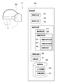
- FIG. 1 is a schematic diagram schematically showing the configuration of an optotype visual recognition determination system according to an embodiment of the present invention.
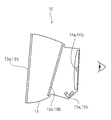
- FIG. 2 is a main-portion cross-sectional view schematically showing the configuration of the HMD according to the embodiment of the present invention.
- FIG. 3 is a main part perspective view schematically showing the configuration of the HMD according to the embodiment of the present invention.
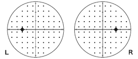
- FIG. 4 is a diagram showing a display position of the measuring optotype according to the embodiment of the present invention.
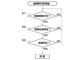
- FIG. 5 is a flowchart showing the flow of the judgment processing of the logical judgment unit according to the embodiment of the present invention.
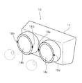
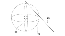
- FIG. 6 is a schematic diagram showing the concept of collision determination of the collision determination unit according to the embodiment of the present invention.
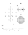
- FIG. 7 is a diagram showing an example of an output screen of the visual field inspection result according to the embodiment of the present invention.
- the target visual recognition determination system 1 is a direction in which the user's eyes are looking, whether the user visually recognizes the target, which is a target displayed on the display device, that is, whether the target is visually recognized. It is a system that automatically detects and determines the line of sight.
- the optotype visual recognition determination system 1 includes a head mounted display (HMD) 10, a control device 30, and a communication cable 60 connecting the HMD 10 and the control device 30.
- HMD head mounted display
- the HMD 10 includes a housing 11 including a belt to be worn on the user's head, a display 13, a convex lens 14, a camera 15, a hot mirror 16, and a near infrared ray emitting section 18, which will be described later.
- a housing 11 including a belt to be worn on the user's head, a display 13, a convex lens 14, a camera 15, a hot mirror 16, and a near infrared ray emitting section 18, which will be described later.
- the line-of-sight detection unit 31 it is possible to perform eye tracking for detecting the line of sight of the user wearing the HMD 10.
- the display 13 is a liquid crystal display, and a user's right-eye display 13a and left-eye display 13b are installed in front of each of the left and right eyes of the user. Between the liquid crystal display 13 and the user's eyes, a right-eye convex lens 14a and a left-eye convex lens 14b are installed on the left and right respectively. The image displayed on the display 13 is visible to the user's eyes through the convex lens 14.
- the camera 15 is a near-infrared camera that captures the user's eyes, and captures the left and right eyes of the user based on the near-infrared light, which is invisible light.
- the camera 15 is also provided with a right-eye camera 15a and a left-eye camera 15b.
- a hot mirror 16 provided with a multilayer film that reflects near infrared rays and transmits visible light is installed.
- the visible light of the image emitted from the display 13 passes through the hot mirror 16, and the near-infrared invisible light emitted from the light emitting unit 18 is reflected by the hot mirror 16.
- the light emitting unit 18 is an LED (IR-LED) that irradiates near infrared rays as illumination for photographing the user's eyes.
- the light emitting units 18a and 18b are installed on the left and right sides of the convex lens 14 so as to face the eyes of the user.
- the camera 15 is installed on the eye side opposite to the display 13 with respect to the hot mirror 16.
- the near-infrared light emitted directly from the light emitting unit 18 to the user's eye is reflected by the user's eye, then reflected by the hot mirror 16 via the convex lens 14, reaches the camera 15, and is imaged.
- the control device 30 includes a computing device 51 such as a CPU (Central Processing Unit) for performing various computations, an HDD (Hard Disc Drive) for storing various information, and a RAM (Random Random Memory) used as a work area for computation processing. Access memory) and the like.
- a computing device 51 such as a CPU (Central Processing Unit) for performing various computations, an HDD (Hard Disc Drive) for storing various information, and a RAM (Random Random Memory) used as a work area for computation processing. Access memory) and the like.
- the storage device 55 includes a line-of-sight log storage unit 56 that records the line-of-sight information detected by the line-of-sight detection unit 31, which will be described later, and an optotype storage unit 57 that records the optotype information displayed on the display 13.
- control device 30 functionally includes a line-of-sight detection unit 31, an optotype display unit 33, and a visual recognition determination unit 40, and these functions are stored in the storage device 55 by the arithmetic unit 51. It is realized by executing a predetermined program that exists.
- the line-of-sight detection unit 31 detects the direction in which the user is looking, that is, the line of sight, based on the captured image of the user's eyes, which is the output of the camera 15. Specifically, the line-of-sight detection unit 31 detects bright spots on the cornea caused by the near-infrared irradiation light of the light emitting units 18a and 18b, respectively. Since the positions of these bright points do not move even if the user moves his or her line of sight, the line-of-sight detection unit 31 sets a two-dimensional coordinate system in the captured image based on the positions of these bright points.
- the line-of-sight detection unit 31 detects the corneal apex that is the center of the anterior surface of the cornea by analyzing the captured image, and obtains the coordinates based on the two-dimensional coordinate system described above, whereby the unit of the line of sight whose origin is the corneal apex.
- a line-of-sight vector which is a vector, can be detected.
- This line-of-sight detection is performed independently for the right eye and the left eye, and line-of-sight information is recorded in the line-of-sight log storage unit 56 in chronological order approximately every 15 ms.
- the line-of-sight information recorded in the line-of-sight log storage unit 56 includes a line-of-sight vector, which is a unit vector indicating the direction of the line of sight, and an item of the origin of the line of sight.
- the optotype display unit 33 sequentially displays optotypes of a predetermined size on the display 13 at predetermined locations based on the optotype information recorded in the optotype storage unit 57.
- the optotypes two optotypes, a gazing optotype for returning the line of sight to near the center for gazing and a measurement optotype for measuring the visual field, are used.
- the target storage unit 57 one measurement target and one fixation target are recorded as one target set.
- FIG. 4 shows the display position of the optotype for measurement.
- 76 points are arranged at grid-like intersections, and 13 points are concentrated in the vicinity of blind points, for a total of 89 points for measurement.
- the target is displayed.
- the viewing angle is 0° when the user is looking at the center of the display 13 and the line of sight crosses the display 13 vertically at the center.
- not all the measurement targets are displayed at the coordinate positions shown in FIG. 4, but all the measurement targets are displayed at a predetermined viewing angle of the display 13 (18 ° in the present embodiment).
- the display position is appropriately adjusted so as to be displayed inside. These adjustments are performed in advance before measurement, and the adjusted position is recorded in the optotype storage unit 57 as optotype information.
- the gaze target is not fixed to the center of the display 13, but is displayed at a position adjusted to the adjustment of the measurement target (a position having the same viewing angle as the position before the adjustment).
- the measurement target is displayed at a position distant from the center of the display 13 and the accuracy of the line-of-sight detection by the line-of-sight detection unit 31 decreases as the angle of inclination of the line of sight with respect to the screen of the display 13 increases.
- the optotype is displayed on the display 13 so as to be positioned within a predetermined viewing angle (18° in the present embodiment) from the center of the optical system.
- the inclination angle of the line of sight with respect to the display 13 is 0° when the user is looking at the center of the display 13 and the line of sight intersects the display 13 vertically at the center, as with the view angle.
- the measurement target when the measurement target is located outside the viewing angle of 18° on the display 13, the measurement target is slid to a position within 18° and displayed on the display 13. Adjust to do. At this time, the previous fixation target is also slid in the same direction as the measurement target by the same distance so that the line-of-sight movement angle from the immediately preceding fixation target of the same set to the measurement target does not change. ..
- the visual recognition determination unit 40 includes a collision determination unit 41 and a logical determination unit 45, and is based on the line of sight detected by the line of sight detection unit 31 and the coordinates of the measurement optotype displayed on the display 13. Determine if the user is viewing the optotype.
- the collision determination unit 41 determines whether the user is visually recognizing the optotype depending on whether or not the extension line in the line-of-sight vector direction detected by the line-of-sight detection unit 31 physically collides with the optotype on a predetermined three-dimensional coordinate system. Judge whether or not.
- the logical determination unit 45 determines from the log of the line-of-sight information whether or not the user visually recognizes the visual target by a logical determination method.
- the RayCast function of "Unity” https://unity3d.com/jp
- Ray of the line-of-sight information oil, line-of-sight vector
- the optotype 71 displayed on the display 13 is a sphere (circle) having a diameter of 2.2567 mm, but when determining a collision, a virtual magnifying sphere having the same center position as the optotype and having a diameter of 20 mm is used.
- the collision determination with the line of sight 75 is performed as 72.
- the virtual magnifying sphere 72 for collision determination is a virtual one used at the time of collision determination, and a small sphere (circle) optotype 71 is displayed on the display 13.
- the virtual magnifying sphere for collision determination is set to become larger as the distance from the center of the optical system of the display 13 increases.
- the diameter of the virtual magnifying sphere is increased by 1 mm as the display position of the optotype increases from 0 ° to 1 ° in the center at the viewing angle.
- the convex lens 14 is installed in the optical system, and as the distance from the center of the optical axis, that is, the center of the display 13, the line-of-sight detection error is more likely to occur due to the influence of aberration and the like. ..
- the size of the virtual magnifying sphere for collision determination can be changed as appropriate, but in order to absorb the error satisfactorily, it is desirable to magnify the size of the virtual magnifying sphere to 5 times the size at which it is displayed on the display.
- the logical determination unit 45 includes a line-of-sight movement determination unit 46, a visual target proximity determination unit 47, and a gaze determination unit 48, and stores the line-of-sight information in the line-of-sight log storage unit 56 of the storage device 55. Based on this, it is logically determined whether or not the user recognizes and looks at the optotype. This determination is performed according to the flowchart shown in FIG.
- the user's line of sight remains at the position of the immediately preceding optotype, and when the user finds the new optotype, the line of sight is updated. After moving toward the target and reaching the position of the new target, it is considered that the user keeps looking at the new target, so that the line of sight remains at the position of the new target.
- the line-of-sight movement determination unit 46 determines the line-of-sight movement.
- the line-of-sight movement determination unit 46 determines whether or not the line of sight of the user is moving, based on the line-of-sight information log recorded in the line-of-sight log storage unit 56.
- the line of sight is Judge that it is moving.
- S1 is repeated every time the line-of-sight information is received until it is determined to be moving, and when it is determined that the S1 is moving, the process proceeds to S2, and the target proximity determination unit 47 determines the target proximity. Do.
- the visual target proximity determination unit 47 determines whether or not the visual line approaches a new visual target. Specifically, the visual target proximity determination unit 47 obtains the angle between the visual line vector from the origin of the visual line vector to the visual target center, and determines this angle. Is close to a predetermined angle (8° or less in the present embodiment), it is determined to be close.
- the process proceeds to S3, and if it is determined that they are not close to each other, the process returns to S1.
- the gaze determination unit 48 performs a gaze determination, and determines whether the user continues to look near the predetermined coordinate position, that is, whether the user is staring at the predetermined coordinate position.
- the gaze determination unit 48 calculates the standard deviation of each component (x, y, z) of a predetermined number (15 in the present embodiment) of the line-of-sight information closest to the line-of-sight information log, respectively.
- the line of sight continues to be located in the vicinity of the predetermined coordinate position for a predetermined time, that is, the user sets the predetermined coordinate position. Determined to be staring.
- the process returns to S1.
- the logical determination unit 45 logically determines that the user is visually recognizing the visual target when the eye movement determination in S1, the visual target proximity determination in S2, and the gaze determination in S3 are all YES. ..
- the method of visual recognition determination by the logical determination unit 45 can be changed as appropriate, and the determination methods of the line-of-sight movement determination unit 46, the visual target proximity determination unit 47, and the gaze determination unit 48 can also be appropriately changed. Further, the order of S1 to S3 can be changed, and further, the visual recognition can be performed by the two determinations of the visual target proximity determination unit 47 and the gaze determination unit 48.
- the configuration of the visual target visual recognition determination system 1 has been described above, and then the visual field inspection method using the visual target visual recognition determination system 1 will be described.
- the visual field inspection unit 49 is provided by executing the visual field inspection program stored in the storage device 55, and the visual field inspection unit 49 can be used as a visual field inspection device by the function of the visual field inspection unit 49.
- the HMD 10 is set on the subject's head, and the visual targets are sequentially displayed on the display 13, so the subject is instructed to always look at the visual targets.
- calibration is first performed and adjustment is performed so that the line-of-sight detection unit 31 can correctly detect the line of sight of the subject.
- the optotype display unit 33 displays the optotype on the display 13.
- the optotype display unit 33 randomly and sequentially displays optotypes for the right eye and optotypes for the left eye on the display 13 based on the optotype information stored in the optotype storage unit 57. ..
- the optotype for the left eye is displayed only on the display 13b for the left eye and the optotype for the right eye is displayed only on the display 13a for the right eye, it is for the right eye or the left eye during the examination. Only one of the targets will be displayed on the right-eye display 13a or the left-eye display 13b.
- the visual target for measurement and the visual target for measurement are recorded as a visual target set, and the visual target display unit 33 displays the visual target for the same set as the visual target for measurement before displaying each visual target for measurement.
- the marker is displayed, and then the optotype for measurement is displayed. That is, the optotype display unit 33 alternately displays the gazing optotype and the measurement optotype on the display 13.
- the visual target display unit 33 switches and displays the next visual target when the visual determination unit 40 determines that the displayed visual target is visually recognized. If the visual target is not visually recognized for 2.5 seconds after the display of the visual target, it is timed out, it is determined that the visual target is not visually recognized, and the next target set is displayed. In addition, when the optotype recognized as time-out is the measurement optotype, the measurement optotype is remeasured. However, depending on the end conditions for each inspection pattern, it may not be subject to remeasurement.
- the virtual magnifying sphere for collision determination is displayed.
- optotypes that partially overlap may be displayed continuously.
- the collision determination unit 41 may determine that the collision has occurred immediately after the display.
- the collision determination unit 41 by inserting a set of dummy optotypes, it is possible to prevent the optotypes from being continuously displayed in the vicinity.
- a dummy optotype set is randomly displayed in an area that is not near the next set of optotypes.
- the line-of-sight detection unit 31 detects the subject's line of sight
- the visual-view determination unit 40 is the output of the line-of-sight detection unit 31. Based on the information, it is determined for each optotype whether or not the subject was visually recognizing it.
- the visual recognition determination unit 40 sequentially makes visual determinations on the gaze target and the measurement target that are sequentially and alternately displayed, based on the line-of-sight information sequentially output from the line-of-sight detection unit 31 after the display of each target. Do. In the visual recognition determination, the visual recognition determination unit 40 first makes a visual recognition determination by the collision determination unit 41, and when it is determined that the line of sight and the target are colliding, the subject is visually recognizing the target. judge.
- the logical determination unit 45 subsequently determines whether or not the subject is visually recognizing the visual target.
- the visual recognition determination unit 40 determines that the subject is visually recognizing the target.
- the visual determination unit 40 remeasures the measurement target. set to target. However, depending on the end conditions for each inspection pattern, it may not be subject to remeasurement. After the visual determination is performed for all the measurement visual targets, the visual recognition determination unit 40 again performs the visual recognition determination for the measurement target to be remeasured.
- the visual target set to be remeasured is also sequentially displayed on the display 13 at random, and the visual identification is judged.
- the visual field inspection unit 49 determined that they were dark spots, and for the measurement optotypes that were determined to be visually recognized by remeasurement, In addition, it will be measured again.
- the measurement target determined to be visually recognized in the third measurement is determined by the visual field inspection unit 49 as not a scotoma, and the measurement target determined not to be visually recognized in the third measurement is , The visual field inspection unit 49 recognizes that it is a dark spot.
- the storage device 55 stores the reaction time as the time from the display of the measurement target to the visual recognition by the subject. Record.
- reaction time In the case of visual recognition determination by the collision determination unit 41, the time from displaying the measurement target to the line of sight of the collision is recorded as the reaction time.
- the reaction time in the case of visual determination by the logical determination unit 45 is calculated as follows. This is because the visual determination by the logical determination unit 45 has a time lag for performing the determination process described above, and therefore the actual reaction time is appropriately corrected and calculated without the time lag.
- the difference from the line-of-sight vector of the line-of-sight when the target is displayed is calculated, and the magnitude of the difference vector is calculated. It is the moving distance of the line of sight when visually recognizing. A value of 90% of this moving distance is used as a threshold.
- the line of sight of all the line-of-sight logs from the time when the target is switched to the time when the gaze is determined, and the moving distance between the line of sight when the target is displayed are similarly obtained, and the threshold value is set at the earliest timing.
- the time until the line of sight that exceeds is defined as the reaction time in the case of the visual recognition determination by the logical determination unit 45.
- the collision determination unit 41 and the logical determination unit 45 accidentally capture the next target or the previous target at the moment when the target is switched because the reaction time is too early. There is a possibility that the line of sight and the target may accidentally collide with each other at the moment when the target is switched because the target is close to the next target. Target for measurement.
- the collision determination unit 41 and the logical determination unit 45 regard the measurement optotype as a remeasurement target because the reaction takes too long.
- the optotype for measurement is the target of remeasurement.
- the visual recognition determination unit 40 outputs the visual field inspection result to a predetermined display device (not shown).
- FIG. 7 is a diagram showing an example of an output screen of the visual field test result.
- FIG. 7A shows the reaction time at each measurement target except for the blind spot in height, and the target to be remeasured has the results of a plurality of measurements displayed side by side.
- FIG. 7B shows the location of the measurement optotype recognized as a dark spot, and the measurement optotype recognized as a dark spot is indicated by a large circle.
- FIG. 7(c) shows both the reaction time with each measurement target and the place recognized as a scotoma in color and shade, and the vicinity of the target with a short reaction time is displayed in light green, and the reaction As the time becomes longer, it is displayed in dark green and the vicinity of the dark spot is displayed in red.
- the reaction time of the optotype for measurement is displayed in association with the visual field angle, and the horizontal axis is the visual field angle and the vertical axis is the reaction time.
- the target visual recognition determination system 1 has been described above, but according to the present embodiment, when determining whether or not the user visually recognizes the target displayed on the display 13,
- the logical determination unit 45 can logically make a determination based on the line-of-sight information log, and even if there is a line-of-sight detection error of the line-of-sight detection unit 31 or the like, the visual recognition determination can be performed with high accuracy. ..
- the collision determination unit 41 determines the collision between the visual target and the visual line, a virtual enlarged sphere for collision determination corresponding to the visual target is used. Even if there is, the visual recognition determination can be performed with high accuracy.
- the visual recognition of the subject can be determined with high accuracy, and the visual field inspection can be performed accurately.
- the visual field test is adjusted so that the visual field for measurement is displayed within a predetermined visual field angle (for example, 18 °) from the center of the optical system of the display 13, and the visual field detection unit. It is possible to stably detect the line of sight with high accuracy and perform a good visual field inspection without lowering the detection accuracy of 31.
- the non-contact type visual line detection unit that estimates the gazing point of the eye from the near-infrared corneal reflection pattern is adopted, but if the line of sight of the user can be detected, the contact type visual line detection unit Etc., other types of line-of-sight detection units can be adopted as appropriate.
- the visual recognition determination unit first makes a visual determination by the collision determination unit, and when it is determined by the collision determination unit that there is no collision, the visual determination unit makes a visual determination by the logical determination unit.
- the visual identification determination may be performed by either the collision determination unit or the logical determination unit, or the visual identification determination may be performed first by the logical determination unit, and the visual identification determination method can be appropriately changed.
- Target visual recognition determination system (visual field inspection device) 10 HMD 11 Case 13 Display 14 Convex Lens 15 Camera 16 Hot Mirror 18 Light Emitting Unit 30 Control Device 31 Line-of-sight Detecting Unit 33 Visual Target Display Unit 40 Visual Determining Unit 41 Collision Determining Unit 45 Logical Determining Unit 46 Visual Line Moving Determining Unit 47 Visual Target Proximity Determination Part 48 Gaze determination part 49 Visual field inspection part 51 Arithmetic device 55 Storage device 56 Line-of-sight log storage part 57 Target storage part 60 Cable 71 Target 72 Virtual magnifying sphere 75 Line of sight
Abstract
L'invention concerne un système de détermination de confirmation visuelle cible, apte à déterminer automatiquement avec une grande précision si un utilisateur a confirmé visuellement une cible. Le système de détermination de confirmation visuelle cible (1) selon l'invention comprend : un dispositif d'affichage (13) destiné à afficher une cible; une unité de détection de ligne de mire (31) destinée à détecter la ligne de mire de l'utilisateur et à émettre en sortie des informations de ligne de mire relatives à la direction de la ligne de mire; un dispositif de stockage (55) destiné à enregistrer un journal des informations de ligne de mire; et une unité de détermination de confirmation visuelle (40) destinée à déterminer, en fonction d'informations de position cible et des informations de ligne de mire, si l'utilisateur a confirmé visuellement la cible ou non, l'unité de détermination de confirmation visuelle (40) étant pourvue d'une unité de détermination d'approche cible (47) destinée à déterminer si la ligne de mire approche de la cible ou non, et d'une unité de détermination de regard fixe (48) destinée à déterminer si la ligne de mire reste à proximité d'une position de coordonnées prédéterminée pendant une durée prédéterminée. L'unité de détermination de confirmation visuelle (40) détermine que l'utilisateur a confirmé visuellement la cible lorsque l'unité de détermination d'approche cible (47) détermine que la ligne de mire s'est approchée de la cible, et l'unité de détermination de regard fixe (48) détermine que la ligne de mire est demeurée à proximité de la position de coordonnées prédéterminée.
Applications Claiming Priority (2)
| Application Number | Priority Date | Filing Date | Title |
|---|---|---|---|
| JP2019040299A JP7246044B2 (ja) | 2019-03-06 | 2019-03-06 | 視標視認判定システム及び視野検査装置 |
| JP2019-040299 | 2019-03-06 |
Publications (1)
| Publication Number | Publication Date |
|---|---|
| WO2020179351A1 true WO2020179351A1 (fr) | 2020-09-10 |
Family
ID=72337373
Family Applications (1)
| Application Number | Title | Priority Date | Filing Date |
|---|---|---|---|
| PCT/JP2020/004703 WO2020179351A1 (fr) | 2019-03-06 | 2020-02-07 | Système de détermination de confirmation visuelle cible et dispositif de vérification de champ de visualisation |
Country Status (2)
| Country | Link |
|---|---|
| JP (1) | JP7246044B2 (fr) |
| WO (1) | WO2020179351A1 (fr) |
Cited By (1)
| Publication number | Priority date | Publication date | Assignee | Title |
|---|---|---|---|---|
| EP4241651A4 (fr) * | 2020-11-05 | 2024-04-17 | Findex Inc | Système d'inspection de caractéristiques |
Citations (3)
| Publication number | Priority date | Publication date | Assignee | Title |
|---|---|---|---|---|
| JPH0924024A (ja) * | 1995-07-11 | 1997-01-28 | Canon Inc | 視線検出装置および視線検出手段を有する機器 |
| JP2015181868A (ja) * | 2014-03-26 | 2015-10-22 | 株式会社ニコン | 眼用レンズ評価方法、眼用レンズ、視力測定装置および眼用レンズ適性検査装置 |
| JP2017529964A (ja) * | 2014-09-30 | 2017-10-12 | イビスヴィジョン リミテッドIbisvision Limited | 患者の視野を検査するための方法、ソフトウェア及び装置 |
-
2019
- 2019-03-06 JP JP2019040299A patent/JP7246044B2/ja active Active
-
2020
- 2020-02-07 WO PCT/JP2020/004703 patent/WO2020179351A1/fr active Application Filing
Patent Citations (3)
| Publication number | Priority date | Publication date | Assignee | Title |
|---|---|---|---|---|
| JPH0924024A (ja) * | 1995-07-11 | 1997-01-28 | Canon Inc | 視線検出装置および視線検出手段を有する機器 |
| JP2015181868A (ja) * | 2014-03-26 | 2015-10-22 | 株式会社ニコン | 眼用レンズ評価方法、眼用レンズ、視力測定装置および眼用レンズ適性検査装置 |
| JP2017529964A (ja) * | 2014-09-30 | 2017-10-12 | イビスヴィジョン リミテッドIbisvision Limited | 患者の視野を検査するための方法、ソフトウェア及び装置 |
Non-Patent Citations (2)
| Title |
|---|
| KAZUYOSHI HOTTA: "Active Visual Field Test Based on VR-HMD", PROCEEDINGS OF THE 80TH NATIONAL CONVENTION OF IPSJ, vol. 80, 13 March 2018 (2018-03-13), pages 4-247 - 4-248, XP009523852 * |
| SATOSHI NAKATOMARI; TOMOMI NISHIDA; MASATERU IWANAMI; TOMOSHIGE HAYASHI; MARIE MIWA; YUKI NISHIWAKI; AKIKO YAMADA; TSUTOMU NAKANIS: "Development of Active Visual Field Measurement System", 31ST CONFERENCE OF THE NATIONAL REHABILITATION CENTER FOR PERSONS WITH DISABILITIES, 19 December 2014 (2014-12-19), pages 51, XP009523533 * |
Cited By (1)
| Publication number | Priority date | Publication date | Assignee | Title |
|---|---|---|---|---|
| EP4241651A4 (fr) * | 2020-11-05 | 2024-04-17 | Findex Inc | Système d'inspection de caractéristiques |
Also Published As
| Publication number | Publication date |
|---|---|
| JP2020141848A (ja) | 2020-09-10 |
| JP7246044B2 (ja) | 2023-03-27 |
Similar Documents
| Publication | Publication Date | Title |
|---|---|---|
| CN107533362B (zh) | 眼睛跟踪设备和用于操作眼睛跟踪设备的方法 | |
| US6659611B2 (en) | System and method for eye gaze tracking using corneal image mapping | |
| EP3153092B1 (fr) | Système de détection de pupille, système de détection du regard, procédé de détection de pupille, et programme de détection de pupille | |
| US9089295B2 (en) | Ophthalmic apparatus and storage medium | |
| JP5578542B2 (ja) | 眼屈折力測定装置 | |
| US20110170060A1 (en) | Gaze Tracking Using Polarized Light | |
| WO2010003410A1 (fr) | Procédé de suivi du regard | |
| US9125597B2 (en) | Ophthalmologic apparatus, and ophthalmologic method and program | |
| US20140132924A1 (en) | Ophthalmic apparatus and alignment determination method | |
| US10959614B2 (en) | Ophthalmologic device and pupil state measuring method | |
| JP7081599B2 (ja) | 情報処理装置、情報処理方法、およびプログラム | |
| CN109964230B (zh) | 用于眼睛度量采集的方法和设备 | |
| US10466780B1 (en) | Systems and methods for eye tracking calibration, eye vergence gestures for interface control, and visual aids therefor | |
| WO2020179351A1 (fr) | Système de détermination de confirmation visuelle cible et dispositif de vérification de champ de visualisation | |
| CN111479494B (zh) | 眼屈光力测定装置 | |
| JP5371051B2 (ja) | 視線計測装置、方法及びプログラム | |
| WO2022097368A1 (fr) | Système d'inspection de caractéristiques | |
| WO2021256100A1 (fr) | Dispositif de test de champ de visualisation | |
| JP4055858B2 (ja) | 視線検出システム | |
| WO2022044548A1 (fr) | Système de détermination de visibilité et dispositif de test de champ visuel | |
| JPH1097376A (ja) | 視線操作装置 | |
| JP5397893B2 (ja) | 眼屈折力測定装置 | |
| JP2016057906A (ja) | 視点位置の計測方法及び計測システム | |
| US20230190091A1 (en) | Visibility Determination System and Visual Field Test Apparatus | |
| JP2022040228A (ja) | 眼科装置及び瞳孔状態計測方法 |
Legal Events
| Date | Code | Title | Description |
|---|---|---|---|
| 121 | Ep: the epo has been informed by wipo that ep was designated in this application |
Ref document number: 20765958 Country of ref document: EP Kind code of ref document: A1 |
|
| NENP | Non-entry into the national phase |
Ref country code: DE |
|
| 122 | Ep: pct application non-entry in european phase |
Ref document number: 20765958 Country of ref document: EP Kind code of ref document: A1 |