WO2020179249A1 - Dispositif de mesure de débit - Google Patents
Dispositif de mesure de débit Download PDFInfo
- Publication number
- WO2020179249A1 WO2020179249A1 PCT/JP2020/001809 JP2020001809W WO2020179249A1 WO 2020179249 A1 WO2020179249 A1 WO 2020179249A1 JP 2020001809 W JP2020001809 W JP 2020001809W WO 2020179249 A1 WO2020179249 A1 WO 2020179249A1
- Authority
- WO
- WIPO (PCT)
- Prior art keywords
- sensor assembly
- housing
- circuit board
- flow rate
- measuring device
- Prior art date
Links
Images


Classifications
-
- G—PHYSICS
- G01—MEASURING; TESTING
- G01F—MEASURING VOLUME, VOLUME FLOW, MASS FLOW OR LIQUID LEVEL; METERING BY VOLUME
- G01F1/00—Measuring the volume flow or mass flow of fluid or fluent solid material wherein the fluid passes through a meter in a continuous flow
- G01F1/68—Measuring the volume flow or mass flow of fluid or fluent solid material wherein the fluid passes through a meter in a continuous flow by using thermal effects
- G01F1/684—Structural arrangements; Mounting of elements, e.g. in relation to fluid flow
- G01F1/6842—Structural arrangements; Mounting of elements, e.g. in relation to fluid flow with means for influencing the fluid flow
-
- G—PHYSICS
- G01—MEASURING; TESTING
- G01F—MEASURING VOLUME, VOLUME FLOW, MASS FLOW OR LIQUID LEVEL; METERING BY VOLUME
- G01F1/00—Measuring the volume flow or mass flow of fluid or fluent solid material wherein the fluid passes through a meter in a continuous flow
- G01F1/68—Measuring the volume flow or mass flow of fluid or fluent solid material wherein the fluid passes through a meter in a continuous flow by using thermal effects
- G01F1/684—Structural arrangements; Mounting of elements, e.g. in relation to fluid flow
-
- G—PHYSICS
- G01—MEASURING; TESTING
- G01F—MEASURING VOLUME, VOLUME FLOW, MASS FLOW OR LIQUID LEVEL; METERING BY VOLUME
- G01F15/00—Details of, or accessories for, apparatus of groups G01F1/00 - G01F13/00 insofar as such details or appliances are not adapted to particular types of such apparatus
- G01F15/14—Casings, e.g. of special material
Definitions
- the present invention relates to a flow rate measuring device that measures the flow rate of a gas to be measured.
- Patent Document 1 As an example of a flow rate measuring device for measuring a gas flow rate, a technique such as Patent Document 1 is disclosed.
- a positioning element is formed in a housing of an air flow meter, and the positioning element is engaged in a positioning element accommodating portion formed in a sensor element support body, whereby an air mass sensor element is formed. Precise positioning in the air guide is disclosed.
- Patent Document 1 does not disclose reducing the dimensional variation in the distance between the detection element and the sub-passage wall surface facing the detection element, and there is room for consideration.
- An object of the present invention is to provide an accurate flow rate measuring device with reduced dimensional variation.
- a flow rate measuring device of the present invention comprises a sensor assembly having a flow rate detecting element, a circuit board on which the sensor assembly is mounted, and a housing on which the circuit board is mounted.
- the assembly is mounted on the circuit board so that the detection section side of the flow rate detection element is on the housing side, and the sensor assembly includes a contact section that contacts the housing on the detection section side.
- FIG. 3 is a sectional view taken along the line AA in FIG. 2 of the thermal type air flow meter in the first embodiment according to the present invention.
- FIG. 3 is a sectional view taken along the line AA in FIG. 2 of the thermal type air flow meter in the first embodiment according to the present invention. It is a bottom view of the circuit board and the sensor assembly in the 2nd Example which concerns on this invention.
- FIG. 6 is a cross-sectional view taken along the line AA on FIG. 2 of the thermal type air flow meter according to the second embodiment of the present invention. It is a bottom view of the circuit board and the sensor assembly in the 2nd Example which concerns on this invention.
- FIG. 5 is a cross-sectional view taken along the line AA of FIG. 2 of the thermal air flow meter according to the third embodiment of the present invention.
- FIG. 6 is a cross-sectional view taken along the line AA on FIG. 2 of the thermal type air flow meter according to the third embodiment of the present invention. It is a top view before the cover attachment of the thermal type air flow meter in 4th Example which concerns on this invention.
- FIG. 13 is a cross-sectional view taken along line BB in FIG. 12 of the thermal type air flow meter according to the fourth embodiment of the present invention. It is a bottom view of the circuit board and the sensor assembly in the 5th Example which concerns on this invention. It is a bottom view of the sensor assembly in the 6th example concerning the present invention.
- FIG. 16 is a sectional view taken along line CC of FIG. 15 showing a circuit board and a sensor assembly according to a sixth embodiment of the present invention.
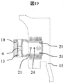
- FIG. 19 is a sectional view taken along line DD of FIG. 18 of the thermal type air flow meter according to the seventh embodiment of the present invention.
- FIG. 19 is a sectional view of the thermal air flow meter according to the seventh embodiment of the present invention taken along the line EE in FIG. 18.
- FIG. 19 is a top view of the circuit board and the sensor assembly in 8th Example which concerns on this invention.
- FIG. 19 is a sectional view taken along the line DD of FIG.
- FIG. 18 is a sectional view taken along line DD of FIG. 18 of the thermal type air flow meter according to the ninth embodiment of the present invention.
- FIG. 19 is a sectional view taken along line DD of FIG. 18 of the thermal type air flow meter according to the ninth embodiment of the present invention.
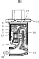
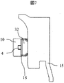
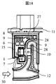
- the first embodiment of the thermal air flow meter will be described with reference to FIGS. 1 to 6.
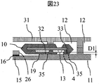
- the thermal air flow meter includes a housing 11 forming a part of the sub passage 12, a cover 31, a circuit board 15 mounted on the housing, and a circuit board. It comprises a sensor assembly 10 that is electrically connected to 15.
- the housing 11 includes the connector terminals 8, and the circuit board 15 is electrically connected to the connector terminals 8 by the wires 9 after being mounted on the housing 11.
- the cover 31 is fixed to the housing 11.
- the cover 31 and the housing 11 are fixed by, for example, an adhesive 17.
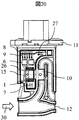
- the housing 11 is formed with a sub-passage groove for forming the sub-passage 12, and cooperates with the cover 31 to form the sub-passage 12 for taking in the air 30, which is the medium to be measured.
- the cover 31 may have a sub-passage groove, and the housing 11 may not have a sub-passage groove.
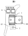
- a circuit board assembly in which the sensor assembly 10 is mounted on the circuit board 15 is configured.
- mounted components such as the pressure sensor 6 and the humidity sensor 7 are electrically connected to the circuit board 15 via the connection portion 14. ..
- the connecting portion 14 include solder and gold wire.
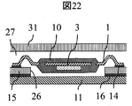
- the sensor assembly 10 is mounted on the circuit board 15 so that the detection unit side of the sensor assembly 10 faces the mounting surface side of the circuit board 15 on which various sensors such as the sensor assembly 10 are mounted.
- the sensor assembly 10 includes the side wall 18 provided so as to project to the upper surface side (housing 11 side) from the detection portion, and the contact portion 32 that contacts the housing 11 is provided on the upper surface of the side wall 18.
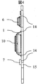
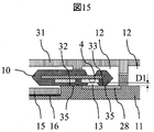
- the sensor assembly 10 includes a lead frame 1, a flow rate detection element 4 arranged on the lead frame 1, and an LSI 3.
- the flow rate detection element 4 is a semiconductor element formed by a MEMS process and includes a thin portion (detection portion) in which a heating element is formed.
- the flow rate detecting element 4 and the LSI 3 are electrically connected via the gold wire 2.
- the sensor assembly 10 is a resin package that seals the flow rate detecting element 4, the LSI 3, and the lead frame 1 with resin, and has a structure in which the flow rate detecting portion of the flow rate detecting element 4 is partially exposed.
- the LSI 3 and the flow rate detecting element 4 may be integrated, or the LSI 3 may be fixed to the circuit board 15.
- the sensor assembly 10 may have a structure in which the flow rate measuring element 4 is mounted on a resin molded body (sensor support body) in which a metal terminal is sealed with resin.
- the sensor assembly 10 includes at least a flow rate detection element and a member that supports the flow rate detection element.
- a circuit assembly in which the sensor assembly 10 is mounted on the circuit board 15 is configured.
- a part of the sensor assembly 10 is arranged so as to project from the circuit board 15.
- the circuit assembly is mounted in the housing 11 that constitutes a part of the wall surface of the sub passage so that the flow rate detecting unit is arranged in the sub passage.
- the sensor assembly 10 is arranged in the housing 11 so that the detection element 4 side is the housing 11 side.
- a part of the sensor assembly 10 on the detection element side is in contact with the housing 11.
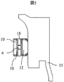
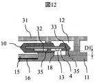
- a circuit board 15 (circuit board assembly) is fixed to the housing 11 by disposing a cushioning material 16 such as an adhesive between the circuit board mounting portion of the housing 11 and the circuit board 15.
- the housing 11 is formed with a step 19 such that the circuit board mounting portion is located outside the sensor assembly contact portion.
- the height of the step 19 is formed to be greater than the height from the bottom surface of the circuit board assembly (the surface opposite to the surface on which the sensor assembly 10 is mounted) to the housing contact portion of the sensor assembly 10.
- the cushioning material 16 is provided so as to fill the gap formed between the bottom surface of the circuit board and the circuit board mounting portion of the housing 11.
- the distance (hereinafter referred to as D1 or D1 dimension) between the flow rate detecting element 4 and the surface of the sub passage 12 facing the flow rate detecting element 4 is a factor that affects noise performance, low flow rate sensitivity, and pulsation performance. is there. Therefore, in order to provide a highly accurate flow rate measuring device, it is extremely important to reduce the dimensional variation of D1.
- D1 or D1 dimension The distance (hereinafter referred to as D1 or D1 dimension) between the flow rate detecting element 4 and the surface of the sub passage 12 facing the flow rate detecting element 4 is a factor that affects noise performance, low flow rate sensitivity, and pulsation performance. is there. Therefore, in order to provide a highly accurate flow rate measuring device, it is extremely important to reduce the dimensional variation of D1.
- the circuit board assembly in which the sensor assembly 10 is mounted on the circuit board 15 is mounted on the housing, if the stacking is simply performed as described in Patent Document 1, the thickness variation of the housing, the sensor assembly, the circuit board, and the
- the sensor assembly 10 is mounted on the circuit board 15 so that the detection portion side of the flow rate detection element 4 is on the housing 11 side, and the sensor assembly 10 detects the contact portion 32 in contact with the housing 11 as the detection portion.
- the configuration provided on the side it is possible to exclude the thickness variation of the circuit board 15 and the cover 31 due to the factor of the D1 dimensional variation, and it is possible to provide an accurate flow rate measuring device.
- the housing 11 has the step 19 because the sensor assembly 10 can be easily brought into contact with the housing 11 when the circuit board assembly is mounted on the housing 11.
- the height of the step 19 is formed to be larger than the height from the bottom surface of the circuit board of the circuit board assembly (the surface opposite to the surface on which the sensor assembly 10 is mounted) to the housing contact portion of the sensor assembly 10. It is more preferable that the cushioning material 16 is provided between the circuit board and the circuit board mounting portion.
- the height of the step is such that there is a gap between the bottom surface of the circuit board and the mounting portion of the circuit board, and the cushioning material 16 is provided between the bottom surface of the circuit board and the mounting portion of the circuit board.
- the cushioning material 16 is preferably made of a material having a low viscosity before curing, such as a silicone adhesive or gel.
- the tip side of the sensor assembly 10 may not have the same height as the contact portion 32 and may have a structure substantially flush with the detection surface of the detection element 4.
- the side wall 18 may not be formed on the tip side.
- the housing of the sensor assembly 10 on the side of the detecting portion of the flow rate detecting element 4 is on the front end side and on the other side of the detecting portion of the flow rate detecting element 4 (on the side where the circuit board 15 is mounted).
- the sensor assembly 10 is housed in the housing 11 so as to come into contact with the 11.
- the sensor assembly 10 has the first contact portion and the second contact portion, which are in contact with the housing 11, on the detection portion side, and the detection portion is located between the first contact portion and the second contact portion. doing.
- the air passage 13 is formed around the flow rate detecting element 4.
- the air passage 13 is opened in the main flow direction of the sub passage 12 by the housing 11 and the sensor assembly 10 coming into contact with the detection portion on the front end side and the other end side in the protruding direction from the circuit board 15. It has a structure that does not open (becomes a minute opening) in the direction that intersects the main flow direction of. That is, it is possible to suppress the flow of the fluid flowing on the detection portion side (front side) of the sensor assembly 10 into the opposite side (back surface side) of the sensor assembly 10. That is, since it is possible to suppress the turbulence of the air around the detection unit, it is possible to improve the flow rate measurement accuracy.
- the first contact portion and the second contact portion of the sensor assembly 10 are in contact with the housing 11, and are not a structure that is firmly fixed to the housing 11 like insert and press fit. Therefore, it is possible to suppress the deformation of the sensor assembly 10 caused by the first contact portion and the second contact portion following the thermal contraction of the housing 11, and thus the first contact portion and the second contact portion. It is possible to reduce the application of bending stress from the starting point to the detection element. Therefore, according to the present embodiment, even if the air passage 13 is formed by the housing 11 and the sensor assembly 10, the stress applied to the detection portion can be reduced, and the characteristic variation due to the deformation of the detection portion can be suppressed. Therefore, it becomes possible to provide an accurate flow rate measuring device.
- the housing 11 and the sensor assembly 10 are brought into contact with each other, and the air passage 13 is formed by the housing 11 and the sensor assembly 10, so that the factor of the dimensional tolerance of the air passage can be determined by the housing 11 and the sensor assembly 10. Since the cover 31 and the circuit board 15 can be reduced due to the factor of the dimensional tolerance, the dimensional tolerance variation can be reduced.
- the present embodiment includes a resin package in which a flow rate detection element is sealed with resin so that at least the detection unit is exposed, a circuit board on which the resin package is mounted, and a housing on which the circuit board is mounted.
- the package is mounted on the circuit board such that the detection unit side is on the housing side, and the resin package has a contact portion that contacts the housing and a detection unit side that the resin package contacts the housing.
- the detection unit is provided between the contact portion of the above and the second contact portion.
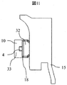
- FIG. 10 shows a modified example of Example 2.
- the tip side of the sensor assembly 10 is made substantially flush with the flow rate detecting surface of the flow rate detecting element 4, and the first contact portion and the second contact portion of the sensor assembly 10 are arranged offset in the thickness direction. Even with the above structure, the same action and effect as in Example 2 can be obtained.
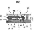
- a third embodiment of the present invention will be described with reference to FIG. The description of the same configuration as that of the previous embodiment will be omitted.
- the housing 11 has a wall surface portion that constitutes the air passage 13, a first contact portion 35 that contacts the first contact portion 32 of the sensor assembly 10, and a second contact portion 33 of the sensor assembly 10. It is configured so that the second contact portion 35 in contact with the second contact portion 35 is substantially on the same plane.
- the housing 11 is formed with a flat surface without steps, and the first contact portion 32 and the second contact portion 35 of the sensor assembly 10 are in contact with the flat surface, and thus the flat surface is formed.
- the detection parts of the detection element 4 face each other. That is, the housing 11 is formed such that the contact portion 35 that comes into contact with the sensor assembly 10 and the facing portion that faces the detecting portion are substantially on the same plane.
- the influence of the thickness variation of the housing 11 can be eliminated from the dimensional variation of D1. That is, the only effect on the D1 dimension is the height variation of the side wall 18 of the sensor assembly 10. Therefore, the D1 dimension can be positioned with higher accuracy.
- the air passage 13 is formed by contacting both ends of the side wall 18 formed by the sensor assembly 10 with the housing 11, it is possible to make the passage closed to the sub passage 12. As a result, the turbulence of the air flowing through the air passage 13 can be suppressed and the height D1 can be positioned with high accuracy, so that the flow rate measurement performance can be further improved. Therefore, the tolerance of the housing 11 does not affect the D1 dimension. Therefore, the influence of the thickness variation of the circuit board 15, the mounting variation of the connecting portion 14 connecting the sensor assembly 10 and the circuit board 15, and the thickness variation of the cover 31 on the height D1 of the air passage 13 is eliminated. Highly accurate positioning of D1 is possible, and flow rate measurement performance is improved.
- a part of the wall surface of the sub passage of the housing 11 is provided with the electrostatic diffusion region 28. It is more preferable that the electrostatic diffusion region 28 is provided in a region facing the detection unit.
- the electrostatic diffusion region 28 has a function of removing the electric charge of dust or the like flying with the air. Dust and other contaminants are charged by friction.
- Wiring that constitutes a heater or the like is formed in the detection portion of the flow rate detection element, and the current flowing through the wiring is attracted to the electric field and deposited on the flow rate detection portion. According to the present embodiment, by removing the electrostatic charge of dust or the like, it becomes possible to suppress the accumulation of contaminants on the flow rate detection unit, and the contamination resistance is improved.
- the electrostatic diffusion region 28 may be made of a conductive resin containing carbon or the like, a metal plate, or a metal plating deposited on the housing.
- the electrostatic diffusion region is preferably fixed at a constant potential, preferably fixed at the GND potential.
- the advantage of forming the electrostatic diffusion region 28 in the housing 11 by inserting the metal plate into the housing 11 is that the rigidity of the housing is improved, and thus the deformation of the shape of the auxiliary passage due to vibration can be suppressed, and the change of D1. Therefore, it is possible to further improve the flow rate measurement accuracy.
- a small step is generated between the surface of the housing 11 and the surface of the metal plate due to the resin riding on the surface of the metal plate, but this can be ignored for the D1 dimensional variation. Since it is the thickness, it is within the range of substantially the same plane in the third embodiment.
- the configuration different from the previous embodiment is that the side wall 18 of the air passage 13 formed by the sensor assembly 10 has a throttle shape so as to narrow toward the flow rate detection element 4.
- the diaphragm when the diaphragm is formed on the wall surface of the sub-passage facing the detection element, it is necessary to form the diaphragm with a member different from the sensor assembly 10.
- the dimensional variation of the different member is included in the D1 dimensional variation.
- the diaphragm By forming the diaphragm on the side wall 18 of the sensor assembly 10, it is possible to exclude the dimensional variation of another member from the flow D1 dimensional variation. In particular, the latter effect becomes greater when combined with the third embodiment.
- the air 30 contracts while remaining parallel to the flow rate detecting surface of the flow rate detecting element 4.
- the frequency with which the pollutant contained in the air 30 collides with the flow rate detection element 4 can be reduced, so that the reliability of the flow rate detection element 4 is improved.
- the air 30 flowing into the air passage 13 moves toward the flow rate detecting element 4 while being contracted by the throttle, so that the inflow speed of the air can be improved, and the air flow rate distribution is stabilized to improve the flow rate measurement sensitivity. Can be improved.
- the side wall 18 with the throttle shape the influence of the throttle on the D1 dimensional variation between the flow rate detection element 4 and the housing 11 is not affected. Therefore, according to the present embodiment, it is possible to prevent the flow rate detection element 4 from being contaminated and further improve the flow rate measurement sensitivity without affecting the D1 dimensional variation. Needless to say, this configuration also has the same effect as that of the previous embodiment.
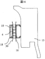
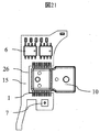
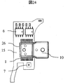
- the configuration different from the previous embodiment is that at least one protrusion 21 is formed on the circuit board 15 side of the sensor assembly 10 as shown in FIGS. 17 and 18.
- the sensor assembly 10 receives a pressing force from, for example, a chip mounter in the direction of the arrow in FIG. Due to this pressing force, the sensor assembly 10 may tilt, and the positioning accuracy of the height D1 of the air passage 13 may decrease.
- the positioning accuracy of the height D1 of the air passage 13 can be maintained with high accuracy. Further, the deformation of the connecting portion 14 between the sensor assembly 10 and the circuit board 15 and the lead frame 1 can be suppressed, and the stress generated in these components can be reduced, so that the reliability of the sensor assembly 10 is improved.
- the protrusions 21 are formed in at least three places of the sensor assembly 10, and the barycentric position 24 of the sensor assembly 10 is located in the region connecting the protrusions 21.
- the sensor assembly 10 can be self-supporting on the circuit board 15, and the inclination of the sensor assembly 10 in the step of connecting to the circuit board 15 can be suppressed. Needless to say, this configuration also has the same effect as that of the previous embodiment.
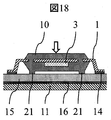
- FIG. 18 is a plan view of the thermal type air flow meter in the seventh embodiment before the cover is attached.
- FIG. 19 is a bottom view of the circuit board and the sensor assembly in the seventh embodiment.
- an opening 26 is formed in a part of the circuit board 15 as shown in FIGS. 18 and 19, and the sensor assembly 10 is arranged in the opening as shown in FIGS. It is a point.
- the height from the housing 11 fixing surface of the circuit board 15 after mounting to the surface of the sensor assembly 10 on the cover 31 side is reduced, and the thickness of the entire thermal air flow meter is reduced to flow through the main passage.
- the pressure loss of the air 30 can be reduced.
- this configuration also has the same effect as that of the previous embodiment.
- the thickness of the thermal air flow meter can be similarly thinned by forming a groove in the circuit board 15 to partially reduce the thickness. it can.
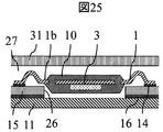
- FIGS. 24-26 The description of the same configuration as that of the previous embodiment will be omitted.
- the configuration different from the previous embodiment is such that, in the circuit board 15 having the opening 26, the circuit board 15 is located immediately below the root straight portion 1b of the lead frame 1 extending to the outside of the sensor assembly 10 as shown in FIG. It is a point where the opening 26 is formed in.
- the sensor assembly 10 receives a pressing force from, for example, a chip mounter in the direction of the arrow in FIG. Due to this pressing force, the sensor assembly 10 may be deformed, and the positioning accuracy of the height D1 of the air passage 13 may be reduced.
- the sensor assembly 10 can be supported by the contact portion when the circuit board 15 and the root straight portion 1b come into contact with each other as shown in FIG. Further deformation of 10 can be suppressed. As a result, it is possible to suppress a decrease in the positioning accuracy of the height D1 of the air passage 13.
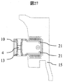
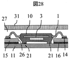
- FIGS. 27 to 29 The description of the same configuration as that of the previous embodiment will be omitted.
- the configuration different from the previous embodiment is that, in the circuit board 15 having the opening 26, the protrusion 21 is formed in at least one location of the sensor assembly 10.
- the protruding portion 21 is provided closer to the connection portion 14 side with the circuit board 15 than the contact portions 32 and 33 with the housing 11.
- the protrusion 21 can support the sensor assembly 10 when a pressing force is applied when fixing the circuit board 15 to the housing 11.
- the deformation of the sensor assembly 10 can be suppressed, and the positioning accuracy of the height D1 of the air passage 13 can be improved.
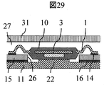
- FIG. 29 it goes without saying that the same effect as that of the previous embodiment can be obtained even if the protrusion 22 is formed on the housing 11 side to support the sensor assembly 10.
Abstract
Le but de la présente invention est d'améliorer la précision de mesure d'un débitmètre d'air de type thermique. Le présent dispositif de mesure de débit comprend : un ensemble capteur qui comprend un élément de détection de débit ; un substrat de circuit sur lequel est monté l'ensemble capteur ; et un boîtier dans lequel est monté le substrat de circuit. L'ensemble capteur est monté sur le substrat de circuit de telle sorte qu'un côté partie de détection de l'élément de détection de débit se trouve sur le côté boîtier. L'ensemble capteur est pourvu, côté partie de détection, d'une partie de contact qui entre en contact avec le boîtier.
Priority Applications (3)
| Application Number | Priority Date | Filing Date | Title |
|---|---|---|---|
| US17/423,946 US11892333B2 (en) | 2019-03-04 | 2020-01-21 | Flow-rate measuring device |
| CN202080006908.7A CN113490837B (zh) | 2019-03-04 | 2020-01-21 | 流量测定装置 |
| DE112020000314.0T DE112020000314T5 (de) | 2019-03-04 | 2020-01-21 | Flussraten-messvorrichtung |
Applications Claiming Priority (2)
| Application Number | Priority Date | Filing Date | Title |
|---|---|---|---|
| JP2019-038139 | 2019-03-04 | ||
| JP2019038139A JP7162961B2 (ja) | 2019-03-04 | 2019-03-04 | 流量測定装置 |
Publications (1)
| Publication Number | Publication Date |
|---|---|
| WO2020179249A1 true WO2020179249A1 (fr) | 2020-09-10 |
Family
ID=72337242
Family Applications (1)
| Application Number | Title | Priority Date | Filing Date |
|---|---|---|---|
| PCT/JP2020/001809 WO2020179249A1 (fr) | 2019-03-04 | 2020-01-21 | Dispositif de mesure de débit |
Country Status (5)
| Country | Link |
|---|---|
| US (1) | US11892333B2 (fr) |
| JP (1) | JP7162961B2 (fr) |
| CN (1) | CN113490837B (fr) |
| DE (1) | DE112020000314T5 (fr) |
| WO (1) | WO2020179249A1 (fr) |
Citations (6)
| Publication number | Priority date | Publication date | Assignee | Title |
|---|---|---|---|---|
| JP2011122984A (ja) * | 2009-12-11 | 2011-06-23 | Hitachi Automotive Systems Ltd | 流量センサとその製造方法、及び流量センサモジュール |
| WO2012049934A1 (fr) * | 2010-10-13 | 2012-04-19 | 日立オートモティブシステムズ株式会社 | Capteur d'écoulement et procédé de production pour celui-ci, et module de capteur d'écoulement et procédé de production pour celui-ci |
| US20130061684A1 (en) * | 2010-05-28 | 2013-03-14 | Rainer Frauenholz | Air mass flow meter |
| WO2017073271A1 (fr) * | 2015-10-28 | 2017-05-04 | 日立オートモティブシステムズ株式会社 | Débitmètre |
| JP2017190948A (ja) * | 2016-04-11 | 2017-10-19 | 日立オートモティブシステムズ株式会社 | 物理量検出装置 |
| JP2018538537A (ja) * | 2015-12-16 | 2018-12-27 | コンチネンタル オートモーティヴ ゲゼルシャフト ミット ベシュレンクテル ハフツングContinental Automotive GmbH | エアフローメータ |
Family Cites Families (9)
| Publication number | Priority date | Publication date | Assignee | Title |
|---|---|---|---|---|
| CN1515878A (zh) * | 1998-08-18 | 2004-07-28 | ͬ�Ϳ�ҵ��ʽ���� | 流量传感器及过滤器一体型流量计 |
| DE10036290A1 (de) | 2000-07-26 | 2002-02-07 | Bosch Gmbh Robert | Vorrichtung zur Bestimmung zumindest eines Parameters eines strömenden Mediums |
| JP2002168669A (ja) | 2000-12-04 | 2002-06-14 | Ckd Corp | 熱式流量計 |
| JP5093052B2 (ja) * | 2008-10-29 | 2012-12-05 | 株式会社デンソー | 熱式流量センサ |
| JP5743871B2 (ja) * | 2011-12-07 | 2015-07-01 | 日立オートモティブシステムズ株式会社 | 熱式流量計 |
| JP5759943B2 (ja) * | 2012-06-15 | 2015-08-05 | 日立オートモティブシステムズ株式会社 | 熱式流量計 |
| JP6043248B2 (ja) * | 2013-07-24 | 2016-12-14 | 日立オートモティブシステムズ株式会社 | 熱式空気流量計 |
| JP6352423B2 (ja) | 2014-07-30 | 2018-07-04 | 日立オートモティブシステムズ株式会社 | 物理量検出装置 |
| JP6272399B2 (ja) * | 2016-06-27 | 2018-01-31 | 日立オートモティブシステムズ株式会社 | 熱式流量計 |
-
2019
- 2019-03-04 JP JP2019038139A patent/JP7162961B2/ja active Active
-
2020
- 2020-01-21 DE DE112020000314.0T patent/DE112020000314T5/de active Pending
- 2020-01-21 CN CN202080006908.7A patent/CN113490837B/zh active Active
- 2020-01-21 US US17/423,946 patent/US11892333B2/en active Active
- 2020-01-21 WO PCT/JP2020/001809 patent/WO2020179249A1/fr active Application Filing
Patent Citations (6)
| Publication number | Priority date | Publication date | Assignee | Title |
|---|---|---|---|---|
| JP2011122984A (ja) * | 2009-12-11 | 2011-06-23 | Hitachi Automotive Systems Ltd | 流量センサとその製造方法、及び流量センサモジュール |
| US20130061684A1 (en) * | 2010-05-28 | 2013-03-14 | Rainer Frauenholz | Air mass flow meter |
| WO2012049934A1 (fr) * | 2010-10-13 | 2012-04-19 | 日立オートモティブシステムズ株式会社 | Capteur d'écoulement et procédé de production pour celui-ci, et module de capteur d'écoulement et procédé de production pour celui-ci |
| WO2017073271A1 (fr) * | 2015-10-28 | 2017-05-04 | 日立オートモティブシステムズ株式会社 | Débitmètre |
| JP2018538537A (ja) * | 2015-12-16 | 2018-12-27 | コンチネンタル オートモーティヴ ゲゼルシャフト ミット ベシュレンクテル ハフツングContinental Automotive GmbH | エアフローメータ |
| JP2017190948A (ja) * | 2016-04-11 | 2017-10-19 | 日立オートモティブシステムズ株式会社 | 物理量検出装置 |
Also Published As
| Publication number | Publication date |
|---|---|
| US20220082421A1 (en) | 2022-03-17 |
| CN113490837B (zh) | 2024-04-23 |
| JP7162961B2 (ja) | 2022-10-31 |
| DE112020000314T5 (de) | 2021-10-28 |
| JP2020143897A (ja) | 2020-09-10 |
| CN113490837A (zh) | 2021-10-08 |
| US11892333B2 (en) | 2024-02-06 |
Similar Documents
| Publication | Publication Date | Title |
|---|---|---|
| CN111033186B (zh) | 热式流量计 | |
| CN105486364B (zh) | 传感器模块 | |
| EP2472236A1 (fr) | Capteur de température d'entrée | |
| JP2001091322A (ja) | 感熱式流量センサ | |
| JP2007033411A (ja) | センサ装置の製造方法及びセンサ装置 | |
| EP3217153B1 (fr) | Débitmètre d'air thermique | |
| WO2015011936A1 (fr) | Débitmètre à air thermique | |
| KR20120065940A (ko) | 반도체 압력 센서 및 그 제조 방법 | |
| JPWO2019064887A1 (ja) | 物理量検出装置 | |
| JP6915160B2 (ja) | 物理量検出装置 | |
| WO2020179249A1 (fr) | Dispositif de mesure de débit | |
| JP6026963B2 (ja) | 流量センサ及び流量検出システム | |
| JP6855590B2 (ja) | 物理量検出装置 | |
| US11821780B2 (en) | Flow rate measurement device | |
| JP7164280B2 (ja) | 物理量検出装置 | |
| JP5601271B2 (ja) | 流量センサ | |
| JP2020034508A (ja) | 物理量検出装置 | |
| JP2014102219A (ja) | 流量センサ | |
| WO2021181782A1 (fr) | Débitmètre de type boîtier | |
| JP7225062B2 (ja) | センサ装置 | |
| JP2020079808A (ja) | 熱式空気流量計 | |
| JP2023038631A (ja) | 耐塵埃/耐ノイズ構造を有するセンサ | |
| JPH1019705A (ja) | 静電容量型物理量センサ |
Legal Events
| Date | Code | Title | Description |
|---|---|---|---|
| 121 | Ep: the epo has been informed by wipo that ep was designated in this application |
Ref document number: 20766071 Country of ref document: EP Kind code of ref document: A1 |
|
| 122 | Ep: pct application non-entry in european phase |
Ref document number: 20766071 Country of ref document: EP Kind code of ref document: A1 |