WO2020179212A1 - 画像形成装置及び画像形成システム - Google Patents
画像形成装置及び画像形成システム Download PDFInfo
- Publication number
- WO2020179212A1 WO2020179212A1 PCT/JP2020/000394 JP2020000394W WO2020179212A1 WO 2020179212 A1 WO2020179212 A1 WO 2020179212A1 JP 2020000394 W JP2020000394 W JP 2020000394W WO 2020179212 A1 WO2020179212 A1 WO 2020179212A1
- Authority
- WO
- WIPO (PCT)
- Prior art keywords
- input
- paper
- cassette
- identification information
- image forming
- Prior art date
- Legal status (The legal status is an assumption and is not a legal conclusion. Google has not performed a legal analysis and makes no representation as to the accuracy of the status listed.)
- Ceased
Links
Images


Classifications
-
- B—PERFORMING OPERATIONS; TRANSPORTING
- B41—PRINTING; LINING MACHINES; TYPEWRITERS; STAMPS
- B41J—TYPEWRITERS; SELECTIVE PRINTING MECHANISMS, i.e. MECHANISMS PRINTING OTHERWISE THAN FROM A FORME; CORRECTION OF TYPOGRAPHICAL ERRORS
- B41J29/00—Details of, or accessories for, typewriters or selective printing mechanisms not otherwise provided for
-
- B—PERFORMING OPERATIONS; TRANSPORTING
- B41—PRINTING; LINING MACHINES; TYPEWRITERS; STAMPS
- B41J—TYPEWRITERS; SELECTIVE PRINTING MECHANISMS, i.e. MECHANISMS PRINTING OTHERWISE THAN FROM A FORME; CORRECTION OF TYPOGRAPHICAL ERRORS
- B41J29/00—Details of, or accessories for, typewriters or selective printing mechanisms not otherwise provided for
- B41J29/38—Drives, motors, controls or automatic cut-off devices for the entire printing mechanism
-
- B—PERFORMING OPERATIONS; TRANSPORTING
- B65—CONVEYING; PACKING; STORING; HANDLING THIN OR FILAMENTARY MATERIAL
- B65H—HANDLING THIN OR FILAMENTARY MATERIAL, e.g. SHEETS, WEBS, CABLES
- B65H1/00—Supports or magazines for piles from which articles are to be separated
- B65H1/26—Supports or magazines for piles from which articles are to be separated with auxiliary supports to facilitate introduction or renewal of the pile
-
- B—PERFORMING OPERATIONS; TRANSPORTING
- B65—CONVEYING; PACKING; STORING; HANDLING THIN OR FILAMENTARY MATERIAL
- B65H—HANDLING THIN OR FILAMENTARY MATERIAL, e.g. SHEETS, WEBS, CABLES
- B65H3/00—Separating articles from piles
-
- B—PERFORMING OPERATIONS; TRANSPORTING
- B65—CONVEYING; PACKING; STORING; HANDLING THIN OR FILAMENTARY MATERIAL
- B65H—HANDLING THIN OR FILAMENTARY MATERIAL, e.g. SHEETS, WEBS, CABLES
- B65H3/00—Separating articles from piles
- B65H3/44—Simultaneously, alternately, or selectively separating articles from two or more piles
-
- G—PHYSICS
- G03—PHOTOGRAPHY; CINEMATOGRAPHY; ANALOGOUS TECHNIQUES USING WAVES OTHER THAN OPTICAL WAVES; ELECTROGRAPHY; HOLOGRAPHY
- G03G—ELECTROGRAPHY; ELECTROPHOTOGRAPHY; MAGNETOGRAPHY
- G03G15/00—Apparatus for electrographic processes using a charge pattern
-
- G—PHYSICS
- G03—PHOTOGRAPHY; CINEMATOGRAPHY; ANALOGOUS TECHNIQUES USING WAVES OTHER THAN OPTICAL WAVES; ELECTROGRAPHY; HOLOGRAPHY
- G03G—ELECTROGRAPHY; ELECTROPHOTOGRAPHY; MAGNETOGRAPHY
- G03G21/00—Arrangements not provided for by groups G03G13/00 - G03G19/00, e.g. cleaning, elimination of residual charge
Definitions
- the present invention relates to an image forming apparatus and an image forming system including the same.
- the image forming apparatus has a paper feed cassette that stores paper. If all users freely take out the paper from the paper feed cassette, the paper may be lost or stolen. Therefore, there is an image forming apparatus configured to lock the paper feed cassette and restrict the taking out of the paper from the paper feed cassette (see Patent Document 1).
- an object of the present invention is to reliably suppress the loss or theft of paper while maintaining the convenience of the image forming apparatus.
- An image forming apparatus includes a paper feed cassette, a lock unit, an input unit, and a control unit.
- the paper cassette stores paper.
- the lock unit locks the paper feed cassette and restricts the removal of paper from the paper feed cassette.
- the input unit accepts the input of the identification information.
- the control unit determines whether or not the correct identification information has been input to the input unit.
- the control unit receives a print processing instruction in a state where the locked paper feed cassette is selected, the input unit receives an input of the identification information, and the correct identification information is The control unit determines whether or not the input is input to the input unit.
- the image forming apparatus When the control unit determines that the correct identification information has been input to the input unit, the image forming apparatus allows sheet feeding from the locked sheet feeding cassette. When the control unit determines that the correct identification information is not input to the input unit, the image forming apparatus regulates the sheet feeding from the locked sheet feeding cassette.
- An image forming system includes the image forming apparatus and a terminal device connected to the image forming apparatus via a network.
- the terminal device includes an input device that receives an input of the identification information.
- FIG. 1 is a schematic front view showing an image forming apparatus according to an embodiment of the present invention.
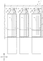
- FIG. 3 is a side view showing a lower portion of the image forming apparatus according to the embodiment of the present invention.
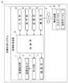
- FIG. 1 is a block diagram showing an image forming system according to an embodiment of the present invention. It is a flow figure which shows one Example of lock control in the image formation system which concerns on one Embodiment of this invention.
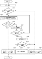
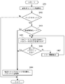
- FIG. 6 is a flowchart showing a first example of copy control in the image forming system according to the embodiment of the present invention.
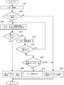
- FIG. 9 is a flowchart showing a second example of copy control in the image forming system according to the embodiment of the present invention.
- FIG. 8 is a flowchart showing an example of lock release control in the image forming system according to the embodiment of the present invention.
- FIGS. 1 and 2 An electrophotographic image forming apparatus 1 according to an embodiment of the present invention will be described below with reference to FIGS. 1 and 2.
- the arrows L, R, U, Lo, Fr, and Rr attached to FIGS. 1 and 2 indicate the left side, the right side, the upper side, the lower side, the front side, and the rear side of the image forming apparatus 1, respectively.
- the image forming apparatus 1 is, for example, a multi-function peripheral having a print function, a copy function, a fax function, and the like.
- the image forming apparatus 1 includes a box-shaped apparatus body 2.
- An image reading device 3 for reading a document image is provided at the upper end of the device body 2.
- a paper output tray 4 is provided below the image reading device 3 in the upper part of the device main body 2.
- four toner containers 5 are accommodated below the paper discharge tray 4.
- An intermediate transfer belt 6 and four image forming units 7 are provided in the central portion of the apparatus main body 2 in the vertical direction.
- Each image forming unit 7 includes a photosensitive drum 8 and a developing device 9.
- An exposure device 10 is provided below the image forming units 7 at the center of the apparatus main body 2 in the vertical direction.
- each paper feed cassette 11 accommodates the paper S.
- three lock parts 12 are provided behind each paper feed cassette 11.
- three paper feeding units 13 are provided on the upper right of each paper feeding cassette 11.
- a paper S transport path 20 is provided on the right side of the apparatus main body 2.
- a secondary transfer unit 21 is provided in the middle stream section with the sheet feeding cassette 11 side of the transport path 20 as the upstream section.
- a fixing device 22 is provided downstream of the transport path 20.
- an electrostatic latent image is formed on the photosensitive drum 8 of each image forming unit 7 by the light from the exposure device 10 (see the dotted arrow in FIG. 1).
- the developing device 9 of each image forming unit 7 develops the electrostatic latent image.
- the toner image is carried on the photosensitive drum 8 of each image forming unit 7.
- This toner image is primarily transferred from the photosensitive drum 8 of each image forming unit 7 to the intermediate transfer belt 6.
- a toner image is formed on the intermediate transfer belt 6.
- the paper S sent from each paper feed cassette 11 to the transport path 20 by each paper feed unit 13 is transported downstream in the transport path 20 and enters the secondary transfer unit 21.
- the toner image formed on the intermediate transfer belt 6 is secondarily transferred to the paper S.
- the sheet S to which the toner image is secondarily transferred is further transported to the downstream side of the transport path 20 and enters the fixing device 22.
- the fixing device 22 the toner image is fixed on the paper S.
- the paper S on which the toner image is fixed is discharged onto the paper discharge tray 4.
- each paper feed cassette 11 and each lock unit 12 will be described with reference to FIG.
- Each paper cassette 11 is inserted in the device main body 2 (see the solid line in FIG. 2) and pulled out from the device main body 2 (see the alternate long and short dash line in FIG. 2) in the front-rear direction. It is held in the device main body 2 so that it can be moved. That is, each sheet feeding cassette 11 is held in the apparatus main body 2 so as to be drawn out.
- a hook 24 projects from the rear surface of each paper cassette 11.
- Each lock part 12 includes a support shaft 26 extending in the left-right direction, a lock piece 27 swingably supported by the support shaft 26, and a solenoid 28 connected to the lock piece 27.
- the lock piece 27 can swing around the support shaft 26 between a lock position (see a solid line in FIG. 2) and an unlock position (see a two-dot chain line in FIG. 2).
- each lock unit 12 will be described with reference to FIG.
- each lock unit 12 When the solenoid 28 of each lock unit 12 is activated while each paper cassette 11 is in the insertion position (see the solid line in FIG. 2), the lock piece 27 of each lock unit 12 is in the unlock position (two-dot chain line in FIG. 2). (See reference line) to the lock position (see the solid line in FIG. 2). Along with this, the lock piece 27 of each lock portion 12 engages with the hook 24 of each paper cassette 11, and moves from the insertion position (see the solid line in FIG. 2) to the pull-out position (see the alternate long and short dash line in FIG. 2). The movement of each paper cassette 11 is restricted. That is, each lock unit 12 locks each paper feed cassette 11. Along with this, the user is restricted from taking out the paper S from each paper cassette 11.
- each lock piece 27 of each lock portion 12 is in the lock position ( It swings from the unlocked position (see the chain double-dashed line in FIG. 2) to the unlock position (see the solid line in FIG. 2).
- the lock piece 27 of each lock portion 12 and the hook 24 of each paper cassette 11 are disengaged, and the insertion position (see the solid line in FIG. 2) to the pull-out position (see the alternate long and short dash line in FIG. 2).
- Movement of each paper cassette 11 to is allowed. That is, the lock of each paper feed cassette 11 by each lock unit 12 is released. Along with this, the user is allowed to take out the paper S from each paper cassette 11.
- the image forming system 30 includes the above-described image forming apparatus 1 and a terminal device 31 connected to the image forming apparatus 1 via the network N.
- the image forming apparatus 1 includes a control unit 34.
- the control unit 34 includes, for example, a CPU (Central Processing Unit).
- the control unit 34 is connected to each part of the image forming apparatus 1 (for example, each image forming unit 7) and controls each part of the image forming apparatus 1.
- the control unit 34 is connected to each lock unit 12 and controls the solenoid 28.
- Each lock unit 12 locks each paper feed cassette 11 based on a signal from the control unit 34, and unlocks each paper feed cassette 11 based on a signal from the control unit 34.
- the control unit 34 is connected to each paper feeding unit 13.
- Each paper feed unit 13 sends out the paper S from each paper feed cassette 11 to the transport path 20 based on a signal from the control unit 34. That is, each sheet feeding unit 13 executes sheet feeding from each sheet feeding cassette 11 based on a signal from the control unit 34.
- the image forming apparatus 1 includes an input unit 35 and a display unit 36.
- the input unit 35 and the display unit 36 are each connected to the control unit 34.
- the input unit 35 includes, for example, various operation keys (for example, a power key and a numeric keypad).
- the input unit 35 accepts various inputs (for example, character input and number input) by the user.
- the display unit 36 may be, for example, a touch panel or a visual user interface with a touch panel.
- the display unit 36 displays various screens (for example, an error message screen), and can also function as a configuration that also functions as the input unit 35 by displaying a keyboard or the like with software.
- the image forming apparatus 1 includes a storage unit 37.
- the storage unit 37 is connected to the control unit 34.
- the storage unit 37 includes, for example, a RAM (Random Access Memory) and a ROM (Read Only Memory).
- the image forming apparatus 1 includes a communication unit 38.
- the communication unit 38 is connected to the control unit 34.
- the communication unit 38 communicates with the terminal device 31 via a network N such as WA (Wide Area Network) or LA (Local Area Network).
- WA Wide Area Network
- LA Local Area Network
- the terminal device 31 is composed of, for example, a personal computer.
- the terminal device 31 includes an input device 41 and a display device 42.
- the input device 41 includes, for example, a keyboard and a mouse.
- the input device 41 accepts various inputs (for example, character input and number input) by the user.
- the display device 42 may be, for example, a display, or a touch panel or a visual user interface with a touch panel.
- the display device 42 displays various screens (for example, an error message screen), and may also function as a configuration that also functions as the input unit 35 by displaying a keyboard or the like with software.
- lock control for deciding whether or not to lock the paper feed cassette 11 (hereinafter referred to as “lock control”) will be described.
- step S101 When the paper cassette 11 is inserted into the apparatus main body 2 (step S101), the display unit 36 displays the password input screen, and the input unit 35 accepts the user's input of the password (an example of identification information) (step S102). ..
- step S102 the control unit 34 determines whether or not the password has been input to the input unit 35 (step S103).
- step S103 If the determination in step S103 is Yes, the lock unit 12 locks the paper feed cassette 11, and the storage unit 37 stores the password input to the input unit 35 (step S104). This ends the lock control.
- step S105 the lock control ends without the lock unit 12 locking the paper feed cassette 11 (step S105).
- the storage unit 37 stores an individual password for each locked sheet feeding cassette 11.
- the storage unit 37 stores the password "1111” for the locked first paper cassette 11, and the storage unit 37 stores the password "2222" for the locked second paper cassette 11.
- the paper feed cassette 11 locked by the lock unit 12 is referred to as “lock cassette 11”
- the paper feed cassette 11 not locked by the lock unit 12 is referred to as “non-lock cassette 11”.
- copy control for executing a copy (an example of a printing process on the paper S) by an input to the input unit 35 of the image forming apparatus 1 will be described.
- copy control an example of a printing process on the paper S
- control unit 34 determines whether or not the lock cassette 11 is selected (step S202). ..
- step S202 If the determination in step S202 is No, the paper feed unit 13 feeds paper from the selected non-lock cassette 11, and the image forming apparatus 1 executes copying (step S203). This ends the copy control.
- step S202 determines whether the password input by the user (step S204).
- step S204 the control unit 34 determines whether the correct password is input to the input unit 35 (step S205). Specifically, the control unit 34 collates the password entered in the input unit 35 with the password stored in the storage unit 37. If the two passwords match, the control unit 34 determines that the correct password has been input to the input unit 35, and if the two passwords do not match, the control unit 34 determines that the correct password has not been input to the input unit 35.
- step S205 If the determination in step S205 is Yes, the paper feed unit 13 feeds paper from the selected lock cassette 11, and the image forming apparatus 1 executes copying (step S206). As a result, copy control ends.
- step S205 determines whether the determination in step S205 is No. If the determination in step S205 is No, the display unit 36 displays an error screen notifying that the password is incorrect (step S207).
- step S207 the display unit 36 displays a screen for selecting whether or not to re-enter the password, and the control unit 34 determines whether or not the re-entry of the password has been input to the input unit 35. Yes (step S208).
- step S208 If the determination in step S208 is Yes, the process returns to step S204, the display unit 36 displays the password input screen, and the input unit 35 accepts the password input by the user.
- step S208 determines whether or not. It should be noted that, for example, the presence/absence of the sheet S and the sheet size are displayed for each unlocked cassette 11 on the selection screen.
- step S210 If the determination in step S210 is Yes, the paper feed unit 13 feeds paper from the unlocked cassette 11 selected in step S210, and the image forming apparatus 1 executes copying (step S203). This ends the copy control.
- step S210 when the determination in step S210 is No, the image forming apparatus 1 does not execute copying (step S211) and the copy control ends.
- step S205 If the determination in step S205 is repeated multiple times, No, it is highly possible that the password has been entered by a user who does not have the correct password. Therefore, in such a case, when the determination in step S205 is repeated No for a predetermined number of times (for example, three times), the image forming apparatus 1 does not execute copying (step S211) and the copy control ends. To do. At this time, the image forming apparatus 1 may return the setting such as the number of determinations in step S205 to the initial state, or display the error screen on the display unit 36 or the display device 42 of the terminal device 31 while maintaining the setting. Then, the paper feed from the unlocked cassette 11 may be selected by operating the input unit 35 or the input device 41 on the error screen.
- a predetermined number of times for example, three times
- the image forming apparatus 1 may return the setting such as the number of determinations in step S205 to the initial state, or display the error screen on the display unit 36 or the display device 42 of the terminal device 31 while maintaining the setting. Then, the
- steps S301 to S308 of the second embodiment of copy control are the same as steps S201 to S208 of the first embodiment of copy control, so description thereof will be omitted.
- step S308 when the determination in step S308 is No, the control unit 34 determines whether the selected paper size of the lock cassette 11 and the paper size of the non-lock cassette 11 match. The determination is made (step S309).
- step S309 If the determination in step S309 is Yes, the paper feed unit 13 automatically feeds paper from the unlocked cassette 11 and the copy is executed (step S303). This ends the copy control.
- step S310 the image forming apparatus 1 does not execute copying (step S310), and the copy control ends.
- the image forming apparatus 1 may announce to the user that the copy can be executed by changing the paper size by the display unit 36, the display device 42 of the terminal device 31, or the like. For example, the paper size entered in the copy instruction. , Or announces that copying can be executed by resetting the paper size of the selected lock cassette 11 to the same as that of the non-lock cassette 11.
- the control for executing printing (an example of printing processing on paper S) by inputting to the input device 41 of the terminal device 31 is the image forming apparatus 1 in the above-mentioned copy control.
- print control By executing the processing executed by using the input unit 35 and the display unit 36 of 1. by using the input device 41 and the display device 42 of the terminal device 31, the same processing as the copy control is executed. Therefore, the description of print control will be omitted.
- the image forming apparatus 1 is configured so that an automatic release mode or a determination release mode can be selected for each paper feed cassette 11 as a mode for unlocking the paper feed cassette 11.
- an automatic release mode or a determination release mode can be selected for each paper feed cassette 11 as a mode for unlocking the paper feed cassette 11.
- a mode of each sheet feeding cassette 11 may be selected by the user via the input unit 35 or the input device 41 of the terminal device 31, or as an initial setting of the image forming apparatus 1, an automatic release mode or The determination cancellation mode may be automatically selected, and the selected mode is stored in the storage unit 37.
- control unit 34 determines whether or not the paper feed cassette 11 is the lock cassette 11 (step S402).
- step S402 If the determination in step S402 is No, there is no need to unlock the paper feed cassette 11, so the unlock control ends.
- step S402 determines whether or not the automatic release mode is selected (step S403).
- step S403 When the determination in step S403 is Yes, since the automatic release mode is selected, the lock unit 12 automatically releases the lock of the paper cassette 11, and the password stored in the storage unit 37 is stored in the control unit 34. Is deleted (step S404). As a result, the unlock control ends.
- step S403 when the determination in step S403 is No, since the deselection mode is selected, the display unit 36 displays the password input screen, and the input unit 35 accepts the password input by the user (step S405). ..
- step S405 the control unit 34 determines whether or not the correct password has been input to the input unit 35 by the same method as in step S205 of the first embodiment of copy control (step S406).
- step S406 If the determination in step S406 is Yes, the lock unit 12 unlocks the paper feed cassette 11, and the control unit 34 deletes the password stored in the storage unit 37 (step S404). As a result, the unlock control ends.
- step S406 determines whether the determination in step S406 is No. If the determination in step S406 is No, the display unit 36 displays an error screen notifying that the password is incorrect (step S407).
- step S407 ends, the process returns to step S405, the display unit 36 displays the password input screen, and the input unit 35 accepts the password input by the user (step S405). Note that when the determination in step S406 is repeated No for a predetermined number of times (for example, three times), the lock release control ends.
- the control unit 34 when the control unit 34 receives the instruction of the printing process with the lock cassette 11 selected, the control unit 34 states that the correct password has been input to the input unit 35. If the control unit 34 determines that the correct password is not input to the input unit 35, the lock cassette 11 is restricted from feeding. ing. By executing such control, the user holding the correct password allows the user to use the sheet S of the lock cassette 11, while the user who does not hold the correct password uses the sheet S of the lock cassette 11. Can be regulated. Therefore, the loss or theft of the paper S can be reliably suppressed while maintaining the convenience of the image forming apparatus 1.
- control unit 34 when the control unit 34 receives an instruction for printing processing with the lock cassette 11 selected, the control unit 34 is input to the input unit 35. By comparing the password stored in the storage unit 37 with the password stored in the storage unit 37, it is determined whether the correct password is input to the input unit 35. By executing such control, it is possible to accurately determine whether or not a correct password has been input.
- the control unit 34 when the control unit 34 receives a print processing instruction with the lock cassette 11 selected, if the correct password is not input to the input unit 35, the control unit When 34 determines, the display unit 36 displays a selection screen on which the non-lock cassette 11 can be selected. By executing such control, it is possible to make a user who does not have a correct password notice that there is a usable sheet S, and it is possible to enhance the convenience of the image forming apparatus 1.
- the control unit 34 when the control unit 34 receives a print processing instruction with the lock cassette 11 selected, if the correct password is not input to the input unit 35, the control unit When the determination is made by 34, the paper is automatically fed from the non-lock cassette 11 on condition that the paper size of the lock cassette 11 and the paper size of the non-lock cassette 11 match.
- the input unit 35 accepts the input of a password, and when the password is input to the input unit 35, When the paper cassette 11 is locked and the password is not input to the input unit 35, the paper cassette 11 is not locked.
- whether or not to lock the paper feed cassette 11 can be determined at an appropriate timing.
- the storage unit 37 stores an individual password for each lock cassette 11. Therefore, a plurality of users can set individual passwords for a plurality of paper feed cassettes 11, and the convenience of the image forming apparatus 1 can be improved.
- the automatic release mode for automatically unlocking the paper feed cassette 11 and the paper S of the lock cassette 11 are eliminated.
- the control unit 34 determines whether or not the correct password has been input to the input unit 35 and then unlocks the paper cassette 11. Therefore, it is possible to select the unlocking method of the paper feed cassette 11 according to the user's request, and the convenience of the image forming apparatus 1 can be improved.
- the terminal device 31 includes an input device 41 that accepts the input of a password.
- the control unit 34 when the control unit 34 receives the print processing instruction with the lock cassette 11 selected, if the control unit 34 determines that the correct password has not been input to the input unit 35, the unlocked cassette is released.
- the display unit 36 displays a selection screen for selecting 11 (see the first embodiment of copy control).
- the control unit 34 when the control unit 34 receives a print processing instruction with the lock cassette 11 selected, the control unit 34 determines that the correct password has not been input to the input unit 35. Then, the display unit 36 may display a selection screen on which the lock cassettes 11 that have not been selected can be selected.
- control unit 34 when the control unit 34 receives a print processing instruction with the lock cassette 11 selected, the control unit 34 determines that the correct password has not been input to the input unit 35. Then, the display unit 36 may display a selection screen on which the lock cassette 11 or the non-lock cassette 11 that is not selected can be selected.
- the image forming apparatus 1 is common to a plurality of lock cassettes 11. If a password is set in advance and one password is input to the input unit 35, the lock cassettes 11 of a plurality of sizes (for example, A4 cassette, A3 cassette) may be made available.
- a plurality of paper feed cassettes 11 and lock units 12 are provided.
- one sheet feed cassette 11 and one lock unit 12 may be provided.
- the terminal device 31 is composed of a personal computer.
- the terminal device 31 may be configured by a device other than a personal computer such as a smartphone.
- the password is used as the identification information.
- information other than the password such as fingerprint authentication, card authentication, and QR code (registered trademark) may be used as the identification information.
- the image forming apparatus 1 is a multi-function peripheral.
- the image forming apparatus 1 may be a printer, a copier, a facsimile, or the like.
- the image forming apparatus 1 employs an electrophotographic method.
- the image forming apparatus 1 may employ an inkjet method.
Landscapes
- Engineering & Computer Science (AREA)
- Mechanical Engineering (AREA)
- Physics & Mathematics (AREA)
- General Physics & Mathematics (AREA)
- Control Or Security For Electrophotography (AREA)
- Sheets, Magazines, And Separation Thereof (AREA)
- Accessory Devices And Overall Control Thereof (AREA)
Abstract
画像形成装置(1)は、用紙を収納する給紙カセット(11)と、給紙カセット(11)をロックして、給紙カセット(11)からの用紙の取り出しを規制するロック部(12)と、識別情報の入力を受け付ける入力部(35)と、正しい識別情報が入力部(35)に入力されたか否かを判定する制御部(34)とを備える。ロックされた給紙カセット(11)が選択された状態で制御部(34)が印字処理の指示を受け付けた場合に、入力部(35)が識別情報の入力を受け付け、正しい識別情報が入力部(35)に入力されたか否かを制御部(34)が判定する。画像形成装置(1)は、正しい識別情報が入力部(35)に入力されたと制御部(34)が判定した場合には、ロックされた給紙カセット(11)からの給紙を許容し、正しい識別情報が入力部(35)に入力されていないと制御部(34)が判定した場合には、ロックされた給紙カセット(11)からの給紙を規制する。
Description
本発明は、画像形成装置及びこれを備えた画像形成システムに関する。
従来、画像形成装置は、用紙を収納する給紙カセットを備えている。この給紙カセットからの用紙の取り出しが全てのユーザーによって自由に行われると、用紙の紛失や盗難につながる恐れがある。そこで、給紙カセットをロックして、給紙カセットからの用紙の取り出しを規制するように構成された画像形成装置がある(特許文献1参照)。
しかしながら、上記のように給紙カセットをロックしても、ロックされた給紙カセットからの給紙が自由に実行されると、用紙が機内の搬送路を通過して機外に排出されることがある。その結果、用紙が機外に持ち出されることになり、用紙の紛失や盗難を確実に抑制することができなくなる。一方で、ロックされた給紙カセットからの給紙を完全に制限してしまうと、ロックされた給紙カセットの用紙に対する印字処理を実行できなくなり、画像形成装置の利便性が損なわれる。
そこで、本発明は、画像形成装置の利便性を保ちつつ、用紙の紛失や盗難を確実に抑制することを目的とする。
本発明の一態様に係る画像形成装置は、給紙カセットと、ロック部と、入力部と、制御部と、を備える。給紙カセットは、用紙を収納する。ロック部は、前記給紙カセットをロックして、前記給紙カセットからの用紙の取り出しを規制する。入力部は、識別情報の入力を受け付ける。制御部は、正しい前記識別情報が前記入力部に入力されたか否かを判定する。画像形成装置は、ロックされた前記給紙カセットが選択された状態で前記制御部が印字処理の指示を受け付けた場合に、前記入力部が前記識別情報の入力を受け付け、正しい前記識別情報が前記入力部に入力されたか否かを前記制御部が判定する。正しい前記識別情報が前記入力部に入力されたと前記制御部が判定した場合には、画像形成装置は、ロックされた前記給紙カセットからの給紙を許容する。正しい前記識別情報が前記入力部に入力されていないと前記制御部が判定した場合には、画像形成装置は、ロックされた前記給紙カセットからの給紙を規制する。
本発明の一態様に係る画像形成システムは、前記画像形成装置と、前記画像形成装置にネットワークを介して接続される端末装置と、を備える。前記端末装置は、前記識別情報の入力を受け付ける入力デバイスを備えている。
本発明によれば、画像形成装置の利便性を保ちつつ、用紙の紛失や盗難を確実に抑制することができる。
以下、図1、図2を参照して、本発明の一実施形態に係る電子写真方式の画像形成装置1について説明する。図1、図2に付される矢印L、R、U、Lo、Fr、Rrは、それぞれ、画像形成装置1の左側、右側、上側、下側、前側、後側を示している。
まず、図1を参照して、画像形成装置1の構成について説明する。画像形成装置1は、例えば、プリント機能、コピー機能及びファックス機能等を複合的に備えた複合機である。
画像形成装置1は、箱型の装置本体2を備えている。装置本体2の上端部には、原稿画像を読み取るための画像読取装置3が設けられている。装置本体2の上部には、画像読取装置3の下方に排紙トレイ4が設けられている。装置本体2の上部には、排紙トレイ4の下方に4個のトナー容器5が収容されている。
装置本体2の上下方向中央部には、中間転写ベルト6と4個の画像形成部7が設けられている。各画像形成部7は、感光体ドラム8と現像装置9を備えている。装置本体2の上下方向中央部には、各画像形成部7の下方に露光装置10が設けられている。
装置本体2の下部には、3個の給紙カセット11が設けられている。各給紙カセット11は、用紙Sを収容している。装置本体2の下部には、各給紙カセット11の後方に3個のロック部12が設けられている。装置本体2の下部には、各給紙カセット11の右上方に3個の給紙部13が設けられている。
装置本体2の右側部には、用紙Sの搬送路20が設けられている。搬送路20の給紙カセット11側を上流部として中流部には、二次転写部21が設けられている。搬送路20の下流部には、定着装置22が設けられている。
次に、図1を参照して、画像形成装置1の動作について説明する。
まず、露光装置10からの光(図1の点線矢印参照)によって、各画像形成部7の感光体ドラム8に静電潜像が形成される。各画像形成部7の現像装置9は、上記の静電潜像を現像する。これにより、各画像形成部7の感光体ドラム8にトナー像が担持される。このトナー像は、各画像形成部7の感光体ドラム8から中間転写ベルト6に一次転写される。これにより、中間転写ベルト6上にトナー像が形成される。
一方で、各給紙部13によって各給紙カセット11から搬送路20へと送り出された用紙Sは、搬送路20を下流側へと搬送されて、二次転写部21に進入する。この二次転写部21において、中間転写ベルト6上に形成されたトナー像が用紙Sに二次転写される。トナー像を二次転写された用紙Sは、搬送路20を更に下流側へと搬送されて、定着装置22に進入する。この定着装置22において、用紙Sにトナー像が定着される。トナー像が定着された用紙Sは、排紙トレイ4上に排出される。
次に、図2を参照して、各給紙カセット11及び各ロック部12の構成について説明する。
各給紙カセット11は、装置本体2に挿入される挿入位置(図2の実線参照)と、装置本体2から引き出される引き出し位置(図2の二点鎖線参照)と、の間で前後方向に移動可能となるように装置本体2に保持されている。即ち、各給紙カセット11は、装置本体2に引き出し可能に保持されている。各給紙カセット11の後面には、フック24が突出している。
各ロック部12は、左右方向に延びる支軸26と、支軸26に揺動可能に支持されるロック片27と、ロック片27に接続されるソレノイド28と、を備えている。ロック片27は、ロック位置(図2の実線参照)とロック解除位置(図2の二点鎖線参照)との間で支軸26を中心に揺動可能となっている。
次に、図2を参照して、各ロック部12の動作について説明する。
各給紙カセット11が挿入位置(図2の実線参照)にある状態で、各ロック部12のソレノイド28が作動すると、各ロック部12のロック片27がロック解除位置(図2の二点鎖線参照)からロック位置(図2の実線参照)まで揺動する。これに伴って、各ロック部12のロック片27が各給紙カセット11のフック24に係合し、挿入位置(図2の実線参照)から引き出し位置(図2の二点鎖線参照)への各給紙カセット11の移動が規制される。即ち、各ロック部12が各給紙カセット11をロックする。これに伴って、ユーザーによる各給紙カセット11からの用紙Sの取り出しが規制される。
一方で、各給紙カセット11が挿入位置(図2の実線参照)にある状態で、各ロック部12のソレノイド28の作動が解除されると、各ロック部12のロック片27がロック位置(図2の実線参照)からロック解除位置(図2の二点鎖線参照)まで揺動する。これに伴って、各ロック部12のロック片27と各給紙カセット11のフック24の係合が解除され、挿入位置(図2の実線参照)から引き出し位置(図2の二点鎖線参照)への各給紙カセット11の移動が許容される。即ち、各ロック部12による各給紙カセット11に対するロックが解除される。これに伴って、ユーザーによる各給紙カセット11からの用紙Sの取り出しが許容される。
次に、図3を参照して、本発明の一実施形態に係る画像形成システム30について説明する。
画像形成システム30は、上述の画像形成装置1と、画像形成装置1にネットワークNを介して接続される端末装置31と、を備えている。
画像形成装置1は、制御部34を備えている。制御部34は、例えば、CPU(Central Processing Unit)を含んでいる。制御部34は、画像形成装置1の各部(例えば、各画像形成部7)に接続されており、画像形成装置1の各部を制御している。
制御部34は、各ロック部12に接続されていてソレノイド28を制御する。各ロック部12は、制御部34からの信号に基づいて各給紙カセット11をロックし、制御部34からの信号に基づいて各給紙カセット11に対するロックを解除する。
制御部34は、各給紙部13に接続されている。各給紙部13は、制御部34からの信号に基づいて各給紙カセット11から搬送路20へ用紙Sを送り出す。即ち、各給紙部13は、制御部34からの信号に基づいて各給紙カセット11からの給紙を実行する。
画像形成装置1は、入力部35と表示部36を備えている。入力部35及び表示部36は、それぞれ制御部34に接続されている。入力部35は、例えば、各種操作キー(例えば、電源キーやテンキー)を含んでいる。入力部35は、ユーザーによる各種入力(例えば、文字入力や数字入力)を受け付ける。表示部36は、例えば、タッチパネルでもよく、あるいは、タッチパネル付きの視覚的ユーザインタフェースでもよい。表示部36は、各種画面(例えば、エラーメッセージ画面)を表示し、更に、キーボード等をソフトウェアで表示して入力部35を兼ねる構成としても機能し得る。
画像形成装置1は、記憶部37を備えている。記憶部37は、制御部34に接続されている。記憶部37は、例えば、RAM(Random Access Memory)やROM(Read Only Memory)を含んでいる。
画像形成装置1は、通信部38を備えている。通信部38は、制御部34に接続されている。通信部38は、例えば、WA(Wide Area Network)やLA(Local Area Network)等のネットワークNを介して端末装置31と通信を行う。
端末装置31は、例えば、パーソナルコンピューターによって構成されている。端末装置31は、入力デバイス41と表示デバイス42を備えている。入力デバイス41は、例えば、キーボードやマウスを含んでいる。入力デバイス41は、ユーザーによる各種入力(例えば、文字入力や数字入力)を受け付ける。表示デバイス42は、例えば、ディスプレイでもよく、あるいは、タッチパネル、若しくはタッチパネル付きの視覚的ユーザインタフェースでもよい。表示デバイス42は、各種画面(例えば、エラーメッセージ画面)を表示し、更に、キーボード等をソフトウェアで表示して入力部35を兼ねる構成としても機能し得る。
次に、図4を参照して、給紙カセット11をロックするか否かを決定するための制御(以下、「ロック制御」と称する)の一実施例について説明する。
給紙カセット11が装置本体2に挿入されると(ステップS101)、表示部36がパスワード入力画面を表示し、ユーザーによるパスワード(識別情報の一例)の入力を入力部35が受け付ける(ステップS102)。
ステップS102が終了すると、パスワードが入力部35に入力されたか否かを制御部34が判定する(ステップS103)。
ステップS103の判定がYesの場合には、ロック部12が給紙カセット11をロックし、入力部35に入力されたパスワードを記憶部37が記憶する(ステップS104)。これにより、ロック制御が終了する。
一方で、ステップS103の判定がNoの場合には、ロック部12が給紙カセット11をロックせずに(ステップS105)、ロック制御が終了する。
なお、上記のようなロック制御が複数の給紙カセット11についてそれぞれ実行され、複数の給紙カセット11がそれぞれロックされる場合、ロックされた給紙カセット11ごとに個別のパスワードを記憶部37が記憶する。例えば、ロックされた第1の給紙カセット11に関しては「1111」というパスワードを記憶部37が記憶し、ロックされた第2の給紙カセット11に関しては「2222」というパスワードを記憶部37が記憶する。以下、ロック部12によってロックされた給紙カセット11のことを「ロックカセット11」と称し、ロック部12によってロックされていない給紙カセット11のことを「非ロックカセット11」と称する。
次に、図5を参照して、画像形成装置1の入力部35への入力によってコピー(用紙Sに対する印字処理の一例)を実行するための制御(以下、「コピー制御」と称する)の第1実施例について説明する。
画像形成装置1の入力部35にコピー指示が入力され、制御部34がコピー指示を受け付けると(ステップS201)、ロックカセット11が選択されているか否かを制御部34が判定する(ステップS202)。
ステップS202の判定がNoの場合には、選択されている非ロックカセット11から給紙部13が給紙し、画像形成装置1がコピーを実行する(ステップS203)。これにより、コピー制御が終了する。
一方で、ステップS202の判定がYesの場合には、表示部36がパスワード入力画面を表示し、ユーザーによるパスワードの入力を入力部35が受け付ける(ステップS204)。
ステップS204が終了すると、正しいパスワードが入力部35に入力されたか否かを制御部34が判定する(ステップS205)。具体的には、入力部35に入力されたパスワードと記憶部37に記憶されたパスワードを制御部34が照合する。両パスワードが一致する場合は正しいパスワードが入力部35に入力されたと制御部34が判定し、両パスワードが一致しない場合は正しいパスワードが入力部35に入力されていないと制御部34が判定する。
ステップS205の判定がYesの場合には、選択されているロックカセット11から給紙部13が給紙し、画像形成装置1がコピーを実行する(ステップS206)。これにより、コピー制御が終了する。
一方で、ステップS205の判定がNoの場合には、パスワードが誤っていることを通知するエラー画面を表示部36が表示する(ステップS207)。
ステップS207が終了すると、パスワードの再入力を行うか否かを選択する画面を表示部36が表示し、パスワードの再入力を行うことが入力部35に入力されたか否かを制御部34が判定する(ステップS208)。
ステップS208の判定がYesの場合には、ステップS204に戻って、表示部36がパスワード入力画面を表示し、ユーザーによるパスワードの入力を入力部35が受け付ける。
一方で、ステップS208の判定がNoの場合には、非ロックカセット11を選択可能な選択画面を表示部36が表示し(ステップS209)、非ロックカセット11の選択が入力部35に入力されたか否かを制御部34が判定する(ステップS210)。なお、上記の選択画面には、例えば、非ロックカセット11ごとに用紙Sの有無や用紙サイズが表示される。
ステップS210の判定がYesの場合には、ステップS210で選択された非ロックカセット11から給紙部13が給紙し、画像形成装置1がコピーを実行する(ステップS203)。これにより、コピー制御が終了する。
一方で、ステップS210の判定がNoの場合には、画像形成装置1がコピーを実行せずに(ステップS211)、コピー制御が終了する。
なお、ステップS205の判定が複数回繰り返しNoになる場合には、正しいパスワードを保持していないユーザーによってパスワードが入力されている可能性が高い。そこで、このような場合には、ステップS205の判定が所定回数(例えば、3回)繰り返しNoになった段階で、画像形成装置1がコピーを実行せずに(ステップS211)、コピー制御が終了する。このとき、画像形成装置1は、ステップS205の判定回数等の設定を初期状態に戻してもよく、あるいは、設定を維持したままエラー画面を表示部36または端末装置31の表示デバイス42に表示させて、このエラー画面に対する入力部35または入力デバイス41の操作によって非ロックカセット11からの給紙を選択できるようにしてもよい。
次に、図6を参照して、コピー制御の第2実施例について説明する。なお、コピー制御の第2実施例のステップS301~ステップS308は、コピー制御の第1実施例のステップS201~ステップS208と同様であるため、説明を省略する。
コピー制御の第2実施例では、ステップS308の判定がNoの場合には、選択されているロックカセット11の用紙サイズと非ロックカセット11の用紙サイズが一致しているか否かを制御部34が判定する(ステップS309)。
ステップS309の判定がYesの場合には、非ロックカセット11から給紙部13が自動的に給紙し、コピーが実行される(ステップS303)。これにより、コピー制御が終了する。
一方で、ステップS309の判定がNoの場合には、画像形成装置1がコピーを実行せずに(ステップS310)、コピー制御が終了する。このとき、画像形成装置1は、用紙サイズの変更によってコピーを実行できることを、表示部36または端末装置31の表示デバイス42等によってユーザーにアナウンスしてよく、例えば、コピー指示で入力された用紙サイズ、または選択されているロックカセット11の用紙サイズを、非ロックカセット11と同じに設定し直すとコピーを実行できることをアナウンスする。
なお、端末装置31の入力デバイス41への入力によってプリント(用紙Sに対する印字処理の一例)を実行するための制御(以下、「プリント制御」と称する)は、上述のコピー制御において画像形成装置1の入力部35と表示部36を用いて実行した処理を端末装置31の入力デバイス41と表示デバイス42を用いて実行することで、コピー制御と同様に実行される。そのため、プリント制御については説明を省略する。
次に、図7を参照して、給紙カセット11のロックを解除するか否かを決定するための制御(以下、「ロック解除制御」と称する)の一実施例について説明する。画像形成装置1は、給紙カセット11のロックを解除するモードとして、各給紙カセット11について自動解除モードと判定解除モードとを選択可能に構成される。例えば、このような各給紙カセット11のモードは、入力部35または端末装置31の入力デバイス41を介してユーザーに選択されてよく、あるいは、画像形成装置1の初期設定として、自動解除モードまたは判定解除モードが自動的に選択されてよく、選択されたモードは、記憶部37に記憶される。
給紙カセット11の用紙Sが無くなると(ステップS401)、その給紙カセット11がロックカセット11であるか否かを制御部34が判定する(ステップS402)。
ステップS402の判定がNoの場合には、給紙カセット11のロックを解除する必要が無いため、そのままロック解除制御が終了する。
一方で、ステップS402の判定がYesの場合には、自動解除モードが選択されているか否かを制御部34が判定する(ステップS403)。
ステップS403の判定がYesの場合には、自動解除モードが選択されているため、ロック部12が給紙カセット11のロックを自動的に解除し、記憶部37に記憶されたパスワードを制御部34が削除する(ステップS404)。これにより、ロック解除制御が終了する。
一方で、ステップS403の判定がNoの場合には、選択解除モードが選択されているため、表示部36がパスワード入力画面を表示し、ユーザーによるパスワードの入力を入力部35が受け付ける(ステップS405)。
ステップS405が終了すると、コピー制御の第1実施例のステップS205と同様の方法により、正しいパスワードが入力部35に入力されたか否かを制御部34が判定する(ステップS406)。
ステップS406の判定がYesの場合には、ロック部12が給紙カセット11のロックを解除し、記憶部37に記憶されたパスワードを制御部34が削除する(ステップS404)。これにより、ロック解除制御が終了する。
一方で、ステップS406の判定がNoの場合には、パスワードが誤っていることを通知するエラー画面を表示部36が表示する(ステップS407)。
ステップS407が終了すると、ステップS405に戻って、表示部36がパスワード入力画面を表示し、ユーザーによるパスワードの入力を入力部35が受け付ける(ステップS405)。なお、ステップS406の判定が所定回数(例えば、3回)繰り返しNoになると、ロック解除制御が終了する。
上述のコピー制御の第1、第2実施例では、ロックカセット11が選択された状態で制御部34が印字処理の指示を受け付けた場合に、正しいパスワードが入力部35に入力されたと制御部34が判定した場合には、ロックカセット11からの給紙が許容され、正しいパスワードが入力部35に入力されていないと制御部34が判定した場合には、ロックカセット11からの給紙が規制されている。このような制御を実行することで、正しいパスワードを保持するユーザーがロックカセット11の用紙Sを使用するのを許容しつつ、正しいパスワードを保持していないユーザーがロックカセット11の用紙Sを使用するのを規制することができる。そのため、画像形成装置1の利便性を保ちつつ、用紙Sの紛失や盗難を確実に抑制することができる。
また、上述のコピー制御の第1、第2実施例では、ロックカセット11が選択された状態で制御部34が印字処理の指示を受け付けた場合に、制御部34は、入力部35に入力されたパスワードと記憶部37に記憶されたパスワードを照合することで、正しいパスワードが入力部35に入力されたか否かを判定している。このような制御を実行することで、正しいパスワードが入力されたか否かを正確に判定することができる。
また、上述のコピー制御の第1実施例では、ロックカセット11が選択された状態で制御部34が印字処理の指示を受け付けた場合に、正しいパスワードが入力部35に入力されていないと制御部34が判定すると、非ロックカセット11を選択可能な選択画面を表示部36が表示している。このような制御を実行することで、正しいパスワードを保持していないユーザーに使用可能な用紙Sがあることを気付かせることができ、画像形成装置1の利便性を高めることができる。
また、上述のコピー制御の第2実施例では、ロックカセット11が選択された状態で制御部34が印字処理の指示を受け付けた場合に、正しいパスワードが入力部35に入力されていないと制御部34が判定すると、ロックカセット11の用紙サイズと非ロックカセット11の用紙サイズが一致していることを条件に、非ロックカセット11から自動的に給紙している。このような制御を実行することで、正しいパスワードを保持していないユーザーでも速やかに印字処理を実行することができ、画像形成装置1の利便性を高めることができる。
なお、以上のようなコピー制御による技術的効果は、画像形成装置1の入力部35と表示部36を端末装置31の入力デバイス41と表示デバイス42に置き換えることで、プリント制御においても同様に発揮される。
また、上述のロック制御の一実施例では、給紙カセット11が装置本体2に挿入されると、入力部35がパスワードの入力を受け付け、パスワードが入力部35に入力される場合には、給紙カセット11がロックされ、パスワードが入力部35に入力されない場合には、給紙カセット11がロックされない。このような制御を実行することで、給紙カセット11をロックするか否かを適切なタイミングで決定することができる。
また、上述のロック制御の一実施例では、記憶部37は、ロックカセット11ごとに個別のパスワードを記憶している。そのため、複数のユーザーが複数の給紙カセット11に対して個別のパスワードを設定することが可能となり、画像形成装置1の利便性を高めることができる。
また、上述のロック解除制御の一実施例では、ロックカセット11の用紙Sが無くなった場合に、給紙カセット11のロックを自動的に解除する自動解除モードと、ロックカセット11の用紙Sが無くなった場合に、正しいパスワードが入力部35に入力されたか否かを制御部34が判定した上で給紙カセット11のロックを解除する判定解除モードと、を選択可能である。そのため、ユーザーの要求に応じて給紙カセット11のロックの解除方法を選択することが可能となり、画像形成装置1の利便性を高めることができる。
また、端末装置31は、パスワードの入力を受け付ける入力デバイス41を備えている。このような構成を採用することで、画像形成装置1の入力部35を用いて実行した処理を端末装置31の入力デバイス41を用いて実行することが可能となる。
本実施形態では、ロックカセット11が選択された状態で制御部34が印字処理の指示を受け付けた場合に、正しいパスワードが入力部35に入力されていないと制御部34が判定すると、非ロックカセット11を選択可能な選択画面を表示部36が表示している(コピー制御の第1実施例参照)。一方で、他の異なる実施形態では、ロックカセット11が選択された状態で制御部34が印字処理の指示を受け付けた場合に、正しいパスワードが入力部35に入力されていないと制御部34が判定すると、選択されてないロックカセット11を選択可能な選択画面を表示部36が表示しても良い。また、更に他の異なる実施例では、ロックカセット11が選択された状態で制御部34が印字処理の指示を受け付けた場合に、正しいパスワードが入力部35に入力されていないと制御部34が判定すると、選択されていないロックカセット11又は非ロックカセット11を選択可能な選択画面を表示部36が表示しても良い。
上記した実施形態では、ロックカセット11毎に個別のパスワードを設定して記憶部37に記憶する例を説明したが、他の実施形態では、画像形成装置1は、複数のロックカセット11に共通のパスワードを予め設定し、1つのパスワードを入力部35に入力すると、複数サイズ(例えば、A4カセット、A3カセット)のロックカセット11を利用可能にしてもよい。
本実施形態では、給紙カセット11及びロック部12が複数設けられている。一方で、他の異なる実施形態では、給紙カセット11及びロック部12が1個ずつ設けられていても良い。
本実施形態では、パーソナルコンピューターによって端末装置31が構成されている。一方で、他の異なる実施形態では、スマートフォン等のパーソナルコンピューター以外の機器によって端末装置31が構成されていても良い。
本実施形態では、パスワードを識別情報として用いている。一方で、他の異なる実施形態では、指紋認証、カード認証、QRコード(登録商標)等のパスワード以外の情報を識別情報として用いても良い。
本実施形態では、画像形成装置1が複合機である。一方で、他の異なる実施形態では、画像形成装置1がプリンター、コピー機、ファクシミリ等であっても良い。本実施形態では、画像形成装置1が電子写真方式を採用している。一方で、他の異なる実施形態では、画像形成装置1がインクジェット方式を採用していても良い。
なお、上記実施形態の説明は、本発明に係る画像形成装置及び画像形成システムにおける一態様を示すものであって、本発明の技術範囲は、上記実施形態に限定されるものではない。
Claims (9)
- 用紙を収納する給紙カセットと、
前記給紙カセットをロックして、前記給紙カセットからの用紙の取り出しを規制するロック部と、
識別情報の入力を受け付ける入力部と、
正しい前記識別情報が前記入力部に入力されたか否かを判定する制御部と、を備え、
ロックされた前記給紙カセットが選択された状態で前記制御部が印字処理の指示を受け付けた場合に、前記入力部が前記識別情報の入力を受け付け、正しい前記識別情報が前記入力部に入力されたか否かを前記制御部が判定し、
正しい前記識別情報が前記入力部に入力されたと前記制御部が判定した場合には、ロックされた前記給紙カセットからの給紙を許容し、
または、正しい前記識別情報が前記入力部に入力されていないと前記制御部が判定した場合には、ロックされた前記給紙カセットからの給紙を規制することを特徴とする画像形成装置。 - 前記給紙カセットを引き出し可能に保持する装置本体を更に備え、
前記給紙カセットが前記装置本体に挿入されると、前記入力部が前記識別情報の入力を受け付け、
前記識別情報が前記入力部に入力された場合には、前記給紙カセットをロックし、
または、前記識別情報が前記入力部に入力されない場合には、前記給紙カセットをロックしないことを特徴とする請求項1に記載の画像形成装置。 - 前記給紙カセットが前記装置本体に挿入された際に前記入力部に入力された前記識別情報を記憶する記憶部を更に備え、
ロックされた前記給紙カセットが選択された状態で前記制御部が印字処理の指示を受け付けた場合に、前記制御部は、前記入力部に入力された前記識別情報と前記記憶部に記憶された前記識別情報を照合することで、正しい前記識別情報が前記入力部に入力されたか否かを判定することを特徴とする請求項2に記載の画像形成装置。 - 前記給紙カセット及び前記ロック部は、複数設けられ、
前記記憶部は、ロックされた前記給紙カセットごとに個別の前記識別情報を記憶することを特徴とする請求項3に記載の画像形成装置。 - 画面を表示する表示部を更に備え、
前記給紙カセット及び前記ロック部は、複数設けられ、
ロックされた前記給紙カセットが選択された状態で前記制御部が印字処理の指示を受け付けた場合に、正しい前記識別情報が前記入力部に入力されていないと前記制御部が判定すると、ロックされていない前記給紙カセットを選択可能な選択画面を前記表示部が表示することを特徴とする請求項1~4のいずれか1項に記載の画像形成装置。 - 前記給紙カセット及び前記ロック部は、複数設けられ、
ロックされた前記給紙カセットが選択された状態で前記制御部が印字処理の指示を受け付けた場合に、正しい前記識別情報が前記入力部に入力されていないと前記制御部が判定すると、ロックされた前記給紙カセットの用紙サイズとロックされていない前記給紙カセットの用紙サイズが一致していることを条件に、ロックされていない前記給紙カセットから自動的に給紙することを特徴とする請求項1~4のいずれか1項に記載の画像形成装置。 - 自動解除モードと判定解除モードとを選択可能であり、
前記自動解除モードが選択されているとき、ロックされた前記給紙カセットの用紙が無くなった場合に、前記給紙カセットのロックを自動的に解除し、
または、前記判定解除モードが選択されているとき、ロックされた前記給紙カセットの用紙が無くなった場合に、前記入力部が前記識別情報の入力を受け付け、正しい前記識別情報が前記入力部に入力されたか否かを前記制御部が判定し、正しい前記識別情報が前記入力部に入力されたと前記制御部が判定した場合には、前記給紙カセットのロックを解除し、正しい前記識別情報が前記入力部に入力されていないと前記制御部が判定した場合には、前記給紙カセットのロックを解除しないことを特徴とする請求項1~4のいずれか1項に記載の画像形成装置。 - 前記給紙カセットは、フックを備え、
前記ロック部は、支軸と、前記支軸に揺動可能に支持されるロック片と、前記ロック片に接続されるソレノイドと、を備え、
前記ロック片は、ロック位置とロック解除位置との間で支軸を中心に揺動可能であり、前記ロック解除位置から前記ロック位置まで揺動すると、前記給紙カセットの前記フックに係合することを特徴とする請求項1に記載の画像形成装置。 - 請求項1に記載の画像形成装置と、
前記画像形成装置にネットワークを介して接続される端末装置と、を備え、
前記端末装置は、前記識別情報の入力を受け付ける入力デバイスを備えていることを特徴とする画像形成システム。
Priority Applications (1)
| Application Number | Priority Date | Filing Date | Title |
|---|---|---|---|
| JP2021503432A JP7124952B2 (ja) | 2019-03-06 | 2020-01-09 | 画像形成装置及び画像形成システム |
Applications Claiming Priority (2)
| Application Number | Priority Date | Filing Date | Title |
|---|---|---|---|
| JP2019040429 | 2019-03-06 | ||
| JP2019-040429 | 2019-03-06 |
Publications (1)
| Publication Number | Publication Date |
|---|---|
| WO2020179212A1 true WO2020179212A1 (ja) | 2020-09-10 |
Family
ID=72337380
Family Applications (1)
| Application Number | Title | Priority Date | Filing Date |
|---|---|---|---|
| PCT/JP2020/000394 Ceased WO2020179212A1 (ja) | 2019-03-06 | 2020-01-09 | 画像形成装置及び画像形成システム |
Country Status (2)
| Country | Link |
|---|---|
| JP (1) | JP7124952B2 (ja) |
| WO (1) | WO2020179212A1 (ja) |
Citations (4)
| Publication number | Priority date | Publication date | Assignee | Title |
|---|---|---|---|---|
| JPH07157138A (ja) * | 1993-12-02 | 1995-06-20 | Ricoh Co Ltd | 給紙段別複写管理装置 |
| JP2001265172A (ja) * | 2000-03-17 | 2001-09-28 | Copyer Co Ltd | 画像形成装置 |
| JP2004021049A (ja) * | 2002-06-19 | 2004-01-22 | Kyocera Mita Corp | 画像形成装置 |
| JP2004053718A (ja) * | 2002-07-17 | 2004-02-19 | Ricoh Co Ltd | 画像形成装置 |
-
2020
- 2020-01-09 JP JP2021503432A patent/JP7124952B2/ja active Active
- 2020-01-09 WO PCT/JP2020/000394 patent/WO2020179212A1/ja not_active Ceased
Patent Citations (4)
| Publication number | Priority date | Publication date | Assignee | Title |
|---|---|---|---|---|
| JPH07157138A (ja) * | 1993-12-02 | 1995-06-20 | Ricoh Co Ltd | 給紙段別複写管理装置 |
| JP2001265172A (ja) * | 2000-03-17 | 2001-09-28 | Copyer Co Ltd | 画像形成装置 |
| JP2004021049A (ja) * | 2002-06-19 | 2004-01-22 | Kyocera Mita Corp | 画像形成装置 |
| JP2004053718A (ja) * | 2002-07-17 | 2004-02-19 | Ricoh Co Ltd | 画像形成装置 |
Also Published As
| Publication number | Publication date |
|---|---|
| JPWO2020179212A1 (ja) | 2020-09-10 |
| JP7124952B2 (ja) | 2022-08-24 |
Similar Documents
| Publication | Publication Date | Title |
|---|---|---|
| JP7243130B2 (ja) | 用紙種類判別装置および用紙種類判別装置の制御プログラム | |
| CN101888463A (zh) | 图像形成设备和由图像形成设备所进行的方法 | |
| JP6256403B2 (ja) | 画像形成装置及び画像形成システム | |
| JP2020134539A (ja) | 画像形成装置 | |
| JP6375136B2 (ja) | 画像形成装置、その制御プログラムおよび動作方法 | |
| JP7124952B2 (ja) | 画像形成装置及び画像形成システム | |
| JP2008078947A (ja) | 画像形成装置 | |
| JP2010273094A (ja) | 画像形成装置、画像形成装置の制御方法、及びプログラム | |
| CN113841091B (zh) | 图像形成装置 | |
| JP7104508B2 (ja) | 画像形成装置、複合機及び画像形成装置に対する制御方法 | |
| JP4833122B2 (ja) | 画像形成装置及び画像形成システム | |
| JP4548436B2 (ja) | 画像形成システム、画像形成装置及び項目設定制御プログラム | |
| JP4472830B2 (ja) | 画像形成装置 | |
| JP5213750B2 (ja) | シート処理装置、シート処理装置の制御方法、及び、プログラム | |
| JP2008114563A (ja) | 画像形成システム,画像形成装置 | |
| JP2001334722A (ja) | 画像形成装置 | |
| JP6838516B2 (ja) | 画像形成装置 | |
| JP2019213077A (ja) | 画像形成装置及び画像形成システム | |
| JP5114332B2 (ja) | 画像形成装置 | |
| JP2018199311A (ja) | 画像形成装置 | |
| JP6197005B2 (ja) | 画像形成装置 | |
| JP2008221469A (ja) | 画像形成装置 | |
| JP2009292619A (ja) | 画像形成装置 | |
| JP4065497B2 (ja) | 画像形成装置 | |
| JP2007112583A (ja) | 画像形成装置 |
Legal Events
| Date | Code | Title | Description |
|---|---|---|---|
| 121 | Ep: the epo has been informed by wipo that ep was designated in this application |
Ref document number: 20766576 Country of ref document: EP Kind code of ref document: A1 |
|
| ENP | Entry into the national phase |
Ref document number: 2021503432 Country of ref document: JP Kind code of ref document: A |
|
| NENP | Non-entry into the national phase |
Ref country code: DE |
|
| 122 | Ep: pct application non-entry in european phase |
Ref document number: 20766576 Country of ref document: EP Kind code of ref document: A1 |