WO2020179153A1 - 照明装置 - Google Patents
照明装置 Download PDFInfo
- Publication number
- WO2020179153A1 WO2020179153A1 PCT/JP2019/046404 JP2019046404W WO2020179153A1 WO 2020179153 A1 WO2020179153 A1 WO 2020179153A1 JP 2019046404 W JP2019046404 W JP 2019046404W WO 2020179153 A1 WO2020179153 A1 WO 2020179153A1
- Authority
- WO
- WIPO (PCT)
- Prior art keywords
- lens
- reflector
- reflecting surface
- light source
- optical axis
- Prior art date
- Legal status (The legal status is an assumption and is not a legal conclusion. Google has not performed a legal analysis and makes no representation as to the accuracy of the status listed.)
- Ceased
Links
Images







Classifications
-
- F—MECHANICAL ENGINEERING; LIGHTING; HEATING; WEAPONS; BLASTING
- F21—LIGHTING
- F21S—NON-PORTABLE LIGHTING DEVICES; SYSTEMS THEREOF; VEHICLE LIGHTING DEVICES SPECIALLY ADAPTED FOR VEHICLE EXTERIORS
- F21S2/00—Systems of lighting devices, not provided for in main groups F21S4/00 - F21S10/00 or F21S19/00, e.g. of modular construction
-
- F—MECHANICAL ENGINEERING; LIGHTING; HEATING; WEAPONS; BLASTING
- F21—LIGHTING
- F21V—FUNCTIONAL FEATURES OR DETAILS OF LIGHTING DEVICES OR SYSTEMS THEREOF; STRUCTURAL COMBINATIONS OF LIGHTING DEVICES WITH OTHER ARTICLES, NOT OTHERWISE PROVIDED FOR
- F21V13/00—Producing particular characteristics or distribution of the light emitted by means of a combination of elements specified in two or more of main groups F21V1/00 - F21V11/00
- F21V13/02—Combinations of only two kinds of elements
-
- F—MECHANICAL ENGINEERING; LIGHTING; HEATING; WEAPONS; BLASTING
- F21—LIGHTING
- F21V—FUNCTIONAL FEATURES OR DETAILS OF LIGHTING DEVICES OR SYSTEMS THEREOF; STRUCTURAL COMBINATIONS OF LIGHTING DEVICES WITH OTHER ARTICLES, NOT OTHERWISE PROVIDED FOR
- F21V13/00—Producing particular characteristics or distribution of the light emitted by means of a combination of elements specified in two or more of main groups F21V1/00 - F21V11/00
- F21V13/12—Combinations of only three kinds of elements
-
- F—MECHANICAL ENGINEERING; LIGHTING; HEATING; WEAPONS; BLASTING
- F21—LIGHTING
- F21V—FUNCTIONAL FEATURES OR DETAILS OF LIGHTING DEVICES OR SYSTEMS THEREOF; STRUCTURAL COMBINATIONS OF LIGHTING DEVICES WITH OTHER ARTICLES, NOT OTHERWISE PROVIDED FOR
- F21V5/00—Refractors for light sources
- F21V5/04—Refractors for light sources of lens shape
-
- F—MECHANICAL ENGINEERING; LIGHTING; HEATING; WEAPONS; BLASTING
- F21—LIGHTING
- F21V—FUNCTIONAL FEATURES OR DETAILS OF LIGHTING DEVICES OR SYSTEMS THEREOF; STRUCTURAL COMBINATIONS OF LIGHTING DEVICES WITH OTHER ARTICLES, NOT OTHERWISE PROVIDED FOR
- F21V7/00—Reflectors for light sources
- F21V7/04—Optical design
- F21V7/06—Optical design with parabolic curvature
-
- F—MECHANICAL ENGINEERING; LIGHTING; HEATING; WEAPONS; BLASTING
- F21—LIGHTING
- F21V—FUNCTIONAL FEATURES OR DETAILS OF LIGHTING DEVICES OR SYSTEMS THEREOF; STRUCTURAL COMBINATIONS OF LIGHTING DEVICES WITH OTHER ARTICLES, NOT OTHERWISE PROVIDED FOR
- F21V7/00—Reflectors for light sources
- F21V7/04—Optical design
- F21V7/08—Optical design with elliptical curvature
-
- F—MECHANICAL ENGINEERING; LIGHTING; HEATING; WEAPONS; BLASTING
- F21—LIGHTING
- F21V—FUNCTIONAL FEATURES OR DETAILS OF LIGHTING DEVICES OR SYSTEMS THEREOF; STRUCTURAL COMBINATIONS OF LIGHTING DEVICES WITH OTHER ARTICLES, NOT OTHERWISE PROVIDED FOR
- F21V7/00—Reflectors for light sources
- F21V7/04—Optical design
- F21V7/09—Optical design with a combination of different curvatures
Definitions
- the present invention relates to a lighting device.
- a lighting device equipped with a cone-shaped specular reflector whose aperture expands from the light source side to the outside is known.
- Such an illuminating device is commonly used because it is easy to design and has high efficiency.
- FIG. 1 is a vertical cross-sectional view for explaining emitted light in a general illumination device 11, and a light path is drawn on the left half surface.
- a part of the light emitted from the light source 15 on the base 16 is reflected by the inner surface of the reflector 12 to become parallel light, but the light not reflected by the inner surface of the reflector 12 spreads radially from the light source 15 and flares. It causes unnecessary light such as glare and glare.
- FIG. 2 is a vertical cross-sectional view for explaining the emitted light in the illuminating device 11 provided with the lens 13, and the path of the light is drawn on the left half surface.
- part of the light emitted from the light source 15 on the base 16 is reflected by the reflector 12 to become parallel light.
- the lens 13 is provided with an effective lens portion in the portion excluding the outer peripheral portion so as to act on the portion through which the light not reflected by the reflector 12 passes, and the light is converted into parallel light by refraction.
- a structure for attaching the lens to the specular reflector is required, and such a mounting structure may interfere with the reflection of light by the specular reflector to prevent normal reflection of light. In such a case, dark areas and dark lines are generated in the emitted light, and the quality and performance (efficiency) of the lighting are deteriorated.
- the present invention has been made in view of the above, and an object of the present invention is to provide a lighting device capable of improving the quality of lighting.
- the lighting device includes a light source, a reflector, and a lens.
- the reflector has a cone-shaped reflecting surface on the inner surface, and the light source is arranged in the opening on the small diameter side.
- the lens is arranged at a middle portion in the optical axis direction of the reflector.
- the reflector has first and second reflecting surfaces divided in the optical axis direction with the lens interposed therebetween, and an end portion of the second reflecting surface closer to the light source on the lens side is The first reflecting surface is located at the same position as or outside of the lens-side end portion when viewed from the optical axis direction.
- the lighting device can improve the quality of lighting.
- FIG. 1 is a vertical cross-sectional view for explaining emitted light in a general lighting device.
- FIG. 2 is a vertical cross-sectional view for explaining the emitted light in the illumination device provided with the lens.
- FIG. 3 is an external perspective view (1) of the lighting device according to the embodiment.
- FIG. 4 is an exploded perspective view (1) showing components of the lighting device.
- FIG. 5 is an external perspective view (2) of the lighting device according to the embodiment.
- FIG. 6 is an exploded perspective view (2) showing components of the lighting device.
- FIG. 7 is a sectional view taken along line AA in FIG.
- FIG. 8 is a diagram showing how light is reflected from the light source by the first paraboloid.
- FIG. 9 is a diagram showing the relationship between the size of the paraboloid and the position of the lens.
- FIG. 1 is a vertical cross-sectional view for explaining emitted light in a general lighting device.
- FIG. 2 is a vertical cross-sectional view for explaining the emitted light in
- FIG. 10 is a figure which shows the state of the intersection of a 1st paraboloid and a lens.
- FIG. 11 is a diagram showing the second paraboloid.
- FIG. 12 is a diagram showing how light from the light source 5 is reflected.
- FIG. 13 is a diagram showing how light is reflected in the comparative example.
- FIG. 14 is a vertical cross-sectional view of a lighting device according to another embodiment.
- the lighting device according to the embodiment will be described with reference to the drawings.
- the present invention is not limited to this embodiment.
- the dimensional relationship of each element in the drawings, the ratio of each element, and the like may differ from reality. Even between the drawings, there may be a case where the dimensional relationships and ratios are different from each other.
- the content described in one embodiment or the modification is similarly applied to other embodiments or the modification in principle.
- FIG. 3 is an external perspective view of the lighting device 1 according to the embodiment, which is viewed from an obliquely upper position.
- FIG. 4 is an exploded perspective view showing the components of the lighting device 1, and is from the same viewpoint as FIG. 3.
- FIG. 5 is an external perspective view of the lighting device 1 from an obliquely downward viewpoint
- FIG. 6 is an exploded perspective view showing components of the lighting device 1 from the same viewpoint as in FIG.
- FIG. 7 is a sectional view taken along line AA in FIG.
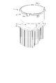
- the lighting device 1 includes a first reflector block 2, a lens 3, a second reflector block 4, a light source 5, and a heat sink 6.
- the lens 3 is sandwiched between the first reflector block 2 and the second reflector block 4.
- the light source 5 is arranged on the heat sink 6, and the heat sink 6 is connected to the second reflector block 4.
- the 1st reflector block 2 and the 2nd reflector block 4 are examples of a reflector.
- the first reflector block 2 is an example of a first reflector block.
- the second reflector block 4 is an example of a second reflector block.
- the first reflector block 2 has a cone portion 2b having a cone-shaped reflecting surface 2a formed on the inner surface thereof, and a cylindrical portion 2c branched from the larger diameter side of the cone portion 2b. A flange portion 2d is provided on the side.
- the reflecting surface 2a is formed by a paraboloid or an ellipsoid having a predetermined function. Paraboloids and ellipsoids are functions of focal length. In this embodiment, the focal length of the reflecting surface is changed appropriately. How the function of the reflecting surface 2a is determined will be described later.
- the reflective surface 2a is an example of a first reflective surface.
- the flange portion 2d of the first reflector block 2 is provided with a plurality of fixing portions 2e, and the fixing portion 2e is provided with screw holes 2f.
- the fixing portion 2e and the screw hole 2f are used to attach the lighting device 1 to another housing or the like (not shown).
- a plurality of boss portions 2g are provided between the cone portion 2b and the cylindrical portion 2c, and the boss portion 2g is provided with a screw hole 2h.
- the boss portion 2g and the screw hole 2h are used for attaching the first reflector block 2 to the second reflector block 4 with the lens 3 sandwiched between them.
- the first reflector block 2 is integrally formed of resin or the like, and the reflecting surface 2a is formed by metal vapor deposition or the like.
- the lens 3 is formed of a substantially disk-shaped flat portion 3b having a lens portion 3a formed of a Fresnel lens in the central portion, and a cutout portion 3c is provided around the flat portion 3b.
- the notch 3c is provided so as not to interfere with the screw when the lens 3 is sandwiched and fixed between the first reflector block 2 and the second reflector block 4.
- the lens portion 3a may be, for example, a convex lens instead of the Fresnel lens.
- the lens 3 is sandwiched between the first reflector block 2 and the second reflector block 4, and the lens 3 is inserted into the screw hole 2h of the boss portion 2g of the first reflector block 2 and the screw hole 4e of the flange portion 4d of the second reflector block 4. It is fixed by a screw 7.
- the second reflector block 4 includes a cone portion 4b having a cone-shaped reflecting surface 4a formed on the inner surface, and a cylindrical portion 4c branched from the large diameter side of the cone portion 4b and having a part of the peripheral surface cut out.
- a flange portion 4d is provided on the large diameter side of the cone portion 4b.
- the reflecting surface 4a is formed by a paraboloid or an ellipsoid having a predetermined function. How the function of the reflecting surface 4a is determined will be described later.
- the reflective surface 4a is an example of a second reflective surface.
- a plurality of screw holes 4e are provided in the flange portion 4d, and the above-mentioned screw 7 is inserted into the screw holes 4e.
- a plurality of boss portions 4f are provided between the cone portion 4b and the cylindrical portion 4c, and the boss portion 4f is provided with a screw hole 4g.
- the boss portion 4f and the screw hole 4g are used for attaching the second reflector block 4 to the heat sink 6.
- the second reflector block 4 is integrally formed of resin or the like, and the reflection surface 4a is formed by metal vapor deposition or the like.
- the light source 5 is a light emitting element such as an LED (Light Emitting Diode) and is fixed on the base 6a of the heat sink 6.
- the base 6a is provided with a plurality of screw holes 6b, and is fixed to the screw holes 4g of the second reflector block 4 by screws (not shown).
- the heat sink 6 has a plurality of fins 6c for heat dissipation.
- the heat sink 6 is made of aluminum alloy or the like.
- one of the reflecting surface 2a of the first reflector block 2 and the reflecting surface 4a of the second reflector block 4 that sandwich the lens 3 is closer to the light source 5.
- the end of the reflecting surface 4a on the lens 3 side is located at the same position or outside the end of the reflecting surface 2a on the lens 3 side when viewed from the optical axis direction. This is to prevent the reflection of light from being hindered by the thick portion that supports the lens 3 and the generation of dark areas and dark lines in the reflected light.
- the relationship between the reflecting surface 2a and the reflecting surface 4a sandwiching the lens 3 can be expressed as the reflecting surface 2a being located inside the extrapolated surface of the reflecting surface 4a.
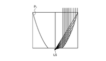
- FIG. 8 is a diagram showing how light is reflected from the light source LS by the first parabolic surface P 1 , and the light path is drawn on the right opposite surface.
- the light source LS corresponds to the light source 5
- the parabolic surface P 1 corresponds to the reflecting surface 2 a of the first reflector block 2.
- FIG. 8 by arranging the light source LS at the focal position of the parabolic surface P 1 , the light emitted from the light source LS to the parabolic surface P 1 is reflected and becomes parallel light.
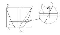
- FIG. 9 is a diagram showing the relationship between the size of the paraboloid P 1 and the position of the lens LE.
- the lens LE corresponds to the lens 3.
- the end of the portion (lens portion) effective as a lens of the lens LE is the radius on the small diameter side. It should be located at the intersection of a straight line drawn from R 2 in the optical axis direction and a straight line connecting the light source LS and the end of the parabolic surface P 1 on the large diameter side.
- Figure 10 is a diagram showing a state of the intersection of the first paraboloid P 1 and the lens LE, and the intersection of the enlarged view of the right side, for example, with the top paraboloid P 1 of the lens LE, A non-reflection area of ⁇ R is generated between the lower surface of the lens LE and the intersection of the parabolic surface P 1 , which causes a dark portion or a dark line.
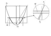
- a new paraboloid P 2 passing through a position below the thickness of the lens LE in the optical axis direction from the intersection of the upper surface of the lens LE and the paraboloid P 1 is formed.
- the parabolic surface P 2 corresponds to the reflecting surface 4 a of the second reflector block 4.
- the focal position of the paraboloid P 2 is the same as the paraboloid P 1, it is necessary to further pass through the ends of the minor axis of the original paraboloid P 1.
- a parabola that defines a paraboloid is expressed by a quadratic equation, and thus, by giving two points to pass through and a focus position, the paraboloid P 2 is uniquely determined.
- parabolic P 1 a case has been described in which thereafter alter the parabolic P 2, on the contrary, it defines a paraboloid P 2 above, varying the paraboloid P 1 on the basis thereof You may do it. Further, if the spread of light can be tolerated within a certain range, the function of the reflection surface 2a of the first reflector block 2 and the function of the reflection surface 4a of the second reflector block 4 may be matched.
- FIG. 12 is a diagram showing the state of light reflection from the light source 5, and the path of light is drawn on the right half surface. Although it is a cross-sectional view, hatching is omitted.
- the lens 3 is sandwiched between the reflecting surface 2 a of the first reflector block 2 and the reflecting surface 4 a of the second reflector block 4, but is reflected at the end of the reflecting surface 2 a on the lens 3 side. There is no blank area between the light and the light reflected by the end of the reflecting surface 4a on the lens 3 side. Therefore, dark areas and dark lines in the irradiation light are eliminated, and the quality of the illumination is improved.
- FIG. 13 is a diagram showing the state of light reflection in the comparative example, and the light path is drawn on the right half surface. It should be noted that although it is a cross-sectional view, hatching is omitted.
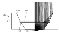
- the illuminating device 101 of the comparative example is provided with a flat portion 102b in the middle of the reflecting surface 102a of the reflector block 102, and the end portion of the lens 103 is supported by the flat portion 102b. .. Therefore, the reflecting surface 102a is divided by the flat portion 102b, and a part of the light from the light source 105 is not reflected, so that a dark portion or a dark line is generated. In this regard, in the embodiment shown in FIG. 12, no dark portion or dark line is generated.
- FIG. 14 is a vertical sectional view of the lighting device 1 according to another embodiment, in which the first reflector block 2 and the second reflector block 4 are integrally formed. Further, a guide groove 2i having an opening in a part of the cylindrical portion 2c is formed at a position which was a boundary portion between the first reflector block 2 and the second reflector block 4, and the lens 3 is provided from the outside to the groove 2i. Is inserted and supported. Other configurations are the same as those in FIGS. 3 to 7.
- optical elements can be provided for both the lighting device 1 shown in FIGS. 3 to 7 and the lighting device 1 shown in FIG.
- the other optical element not only a lens for controlling light distribution but also various elements for improving the function of the lighting device 1 such as an optical filter for light diffusion and wavelength limitation can be used.
- the first reflector block 2 in FIG. 7 is divided in the optical axis direction, and a structure similar to that for supporting the lens 3 is added to the divided portion, so that other optical elements can be supported. Further, by adding a guide groove into which another optical element is inserted, similar to the groove 2i supporting the lens 3, in the middle of the first reflector block 2 in FIG. Is possible.
- the first reflector block 2 has a third reflecting surface that has a function different from that of the first reflecting surface and that faces the first reflecting surface with the optical element interposed therebetween.
- the side end is located on the same side as or outside the optical element side end of the third reflecting surface when viewed from the optical axis direction.
- the illumination device includes a light source, a reflector having a cone-shaped reflection surface on the inner surface, the light source being arranged in the opening on the small diameter side, and arranged in the middle of the reflector in the optical axis direction.
- the reflector has a first and a second reflecting surface divided in the optical axis direction with the lens in between, and the lens-side end portion of the second reflecting surface close to the light source. Is located on the same side or outside the lens-side end of the first reflecting surface when viewed in the optical axis direction.
- a light source a reflector having a cone-shaped reflecting surface on the inner surface, the light source being arranged in the opening on the small diameter side, and a lens arranged in the middle of the optical axis direction of the reflector, the reflector, It has a 1st and 2nd reflective surface divided
- the first and second reflecting surfaces have different functions representing the reflecting surfaces. This makes it possible to more accurately adjust the reflection of light at the divided portions.
- the functions representing the first and second reflecting surfaces have different focal lengths. This makes it possible to more accurately adjust the reflection of light at the divided portions.
- the reflector includes a first reflector block having a first reflecting surface and a second reflector block having a second reflecting surface, and the lens has a first reflector block and a second reflector block. It is sandwiched and supported by. This allows the lens to be easily supported by the reflector.
- the lens is inserted and supported in a groove for a guide provided between the first reflecting surface and the second reflecting surface. This allows the lens to be easily supported by the reflector.
- first reflecting surface and the second reflecting surface are paraboloids or ellipsoids whose focal positions are aligned with the positions of the light sources. This makes it possible to easily design in consideration of light reflection.
- the reflector is provided with an optical element arranged in a middle portion on a larger diameter side than the lens, and the reflector has a third reflecting surface facing the first reflecting surface with the optical element interposed therebetween, The end of the reflecting surface on the optical element side is located on the same side as or outside the end of the third reflecting surface on the optical element side when viewed from the optical axis direction. As a result, the function of the lighting device can be improved.
- the present invention is not limited to the above embodiment.
- the present invention also includes those configured by appropriately combining the constituent elements described above. Further, further effects and modified examples can be easily derived by those skilled in the art. Therefore, the broader aspect of the present invention is not limited to the above-described embodiment, and various modifications can be made.
Landscapes
- Engineering & Computer Science (AREA)
- General Engineering & Computer Science (AREA)
- Non-Portable Lighting Devices Or Systems Thereof (AREA)
Abstract
実施形態の照明装置は、光源(5)と、リフレクタ(2、4)と、レンズ(3)とを備える。リフレクタ(2、4)は、内面にコーン形状の反射面(2a、4a)を有し、光源(5)が小径側の開口部に配置される。レンズ(3)は、リフレクタ(2、4)の光軸方向の中途部分に配置される。リフレクタ(2、4)は、レンズ(3)を挟んで光軸方向に分割された第1および第2の反射面(2a、4a)を有し、光源(5)に近い側の第2の反射面(4a)のレンズ(3)側の端部は、第1の反射面(2a)のレンズ(3)側の端部に対し、光軸方向から見て同じか外側に位置する。
Description
本発明は、照明装置に関する。
光源側より外側に向けて口径が広がるコーン形状の鏡面リフレクタを備えた照明装置が知られている。このような照明装置は、設計が容易であるとともに、効率も高いことから、一般的に使用されている。
しかし、鏡面リフレクタに当たらずに光源から直接に出射される光は、鏡面リフレクタにより制御することができないため、フレアやグレアの原因となる不要な光となってしまい、照明の品位が悪化してしまうことがある。図1は、一般的な照明装置11における出射光を説明するための縦断面図であり、左半面について光の経路が描かれている。図1において、基台16上の光源15から出射した光の一部はリフレクタ12の内面により反射されて平行光となるが、リフレクタ12の内面により反射されない光は光源15から放射状に広がり、フレアやグレアといった不要な光の原因となる。
そのため、鏡面リフレクタにレンズを組み合わせることで、光源から出射される光のうち鏡面リフレクタに当たらない光を制御することが行われている(たとえば、特許文献1、2を参照)。図2は、レンズ13が設けられた照明装置11における出射光を説明するための縦断面図であり、左半面について光の経路が描かれている。図2において、基台16上の光源15から出射した光の一部はリフレクタ12により反射されて平行光となる。また、レンズ13はリフレクタ12により反射されない光が通過する部分に作用するように、外周部分を除いた部分に有効なレンズ部分が設けられており、屈折により光を平行光に変える。
しかしながら、レンズを用いる場合には、鏡面リフレクタにレンズを取り付けるための構造が必要となり、このような取付構造が鏡面リフレクタによる光の反射を妨げて正常な光の反射が行われない場合がある。そのような場合、出射される光に暗部や暗線が生じてしまい、照明の品位や性能(効率)が悪化してしまう。
本発明は、上記に鑑みてなされたものであって、照明の品位を向上させることのできる照明装置を提供することを目的とする。
上述した課題を解決し、目的を達成するために、本発明の一態様に係る照明装置は、光源と、リフレクタと、レンズとを備える。前記リフレクタは、内面にコーン形状の反射面を有し、前記光源が小径側の開口部に配置される。前記レンズは、前記リフレクタの光軸方向の中途部分に配置される。前記リフレクタは、前記レンズを挟んで光軸方向に分割された第1および第2の反射面を有し、前記光源に近い側の前記第2の反射面の前記レンズ側の端部は、前記第1の反射面の前記レンズ側の端部に対し、光軸方向から見て同じか外側に位置する。
本発明の一態様に係る照明装置は、照明の品位を向上させることができる。
以下、実施形態に係る照明装置について図面を参照して説明する。なお、この実施形態によりこの発明が限定されるものではない。また、図面における各要素の寸法の関係、各要素の比率などは、現実と異なる場合がある。図面の相互間においても、互いの寸法の関係や比率が異なる部分が含まれている場合がある。また、1つの実施形態や変形例に記載された内容は、原則として他の実施形態や変形例にも同様に適用される。
図3は、一実施形態にかかる照明装置1の外観斜視図であり、斜め上方からの視点によるものである。図4は、照明装置1の構成要素を示す分解斜視図であり、図3と同じ視点によるものである。また、図5は、斜め下方からの視点による照明装置1の外観斜視図であり、図6は、図5と同じ視点での照明装置1の構成要素を示す分解斜視図である。図7は、図3におけるA-A断面図である。
図3~図7において、照明装置1は、第1リフレクタブロック2と、レンズ3と、第2リフレクタブロック4と、光源5と、ヒートシンク6とを備えている。レンズ3は、第1リフレクタブロック2と第2リフレクタブロック4との間に挟まれている。ヒートシンク6に光源5が配置され、ヒートシンク6は第2リフレクタブロック4に接続される。第1リフレクタブロック2および第2リフレクタブロック4は、リフレクタの一例である。第1リフレクタブロック2は第1のリフレクタブロックの一例である。第2リフレクタブロック4は、第2のリフレクタブロックの一例である。
第1リフレクタブロック2は、内面にコーン形状の反射面2aが形成されたコーン部2bと、コーン部2bの大径側から分岐する円筒部2cとを有しており、コーン部2bの大径側にはフランジ部2dが設けられている。反射面2aは所定の関数の放物面や楕円面により形成されている。放物面や楕円面は、焦点距離の関数である。本実施形態では、反射面の焦点距離を適宜に変えている。反射面2aの関数がどのように定められるかについては後述する。反射面2aは、第1の反射面の一例である。
第1リフレクタブロック2のフランジ部2dには、複数の固定部2eが設けられ、固定部2eにはネジ孔2fが設けられている。固定部2eおよびネジ孔2fは、図示されない他の筐体等に照明装置1が取り付けられるのに用いられる。コーン部2bと円筒部2cとの間には、複数のボス部2gが設けられ、ボス部2gにはネジ孔2hが設けられている。ボス部2gおよびネジ孔2hは、レンズ3が挟まれた状態で、第1リフレクタブロック2が第2リフレクタブロック4に取り付けられるのに用いられる。第1リフレクタブロック2は樹脂等により一体に形成され、反射面2aは金属蒸着等により形成される。
レンズ3は、中央部にフレネルレンズによるレンズ部3aが設けられた略円板状の平坦部3bから形成され、平坦部3bの周辺には切欠部3cが設けられている。切欠部3cは、レンズ3が第1リフレクタブロック2と第2リフレクタブロック4とに挟まれて固定される場合において、ネジと干渉しないために設けられている。なお、レンズ部3aは、フレネルレンズに代えて例えば凸レンズとしてもよい。レンズ3は、第1リフレクタブロック2と第2リフレクタブロック4との間に挟まれ、第1リフレクタブロック2のボス部2gのネジ孔2hに、第2リフレクタブロック4のフランジ部4dのネジ孔4eを通してネジ7により固定される。
第2リフレクタブロック4は、内面にコーン形状の反射面4aが形成されたコーン部4bと、コーン部4bの大径側から分岐する、周面の一部が切り欠かれた円筒部4cとを有しており、コーン部4bの大径側にはフランジ部4dが設けられている。反射面4aは所定の関数の放物面や楕円面により形成されている。反射面4aの関数がどのように定められるかについては後述する。反射面4aは、第2の反射面の一例である。
フランジ部4dには、複数のネジ孔4eが設けられ、前述のネジ7はネジ孔4eに挿入される。コーン部4bと円筒部4cとの間には、複数のボス部4fが設けられ、ボス部4fにはネジ孔4gが設けられている。ボス部4fおよびネジ孔4gは、第2リフレクタブロック4がヒートシンク6に取り付けられるのに用いられる。第2リフレクタブロック4は樹脂等により一体に形成され、反射面4aは金属蒸着等により形成される。
光源5は、LED(Light Emitting Diode)等の発光素子であり、ヒートシンク6の基台6a上に固定されている。基台6aには複数のネジ孔6bが設けられ、図示しないネジにより第2リフレクタブロック4のネジ孔4gに固定される。ヒートシンク6は、複数の放熱用のフィン6cを有している。ヒートシンク6は、アルミニウム合金等により形成される。
なお、図7に部分的に拡大されて示されているように、レンズ3を挟んだ第1リフレクタブロック2の反射面2aと第2リフレクタブロック4の反射面4aのうち、光源5に近い側の反射面4aのレンズ3側の端部は、反射面2aのレンズ3側の端部に対し、光軸方向から見て同じか外側に位置するようになっている。これは、レンズ3を支持する厚みの部分により光の反射が妨げられ、反射光に暗部・暗線が発生することを防止するためである。また、レンズ3を挟んだ反射面2aと反射面4aとの関係は、反射面2aは反射面4aの外挿面よりも内側に位置していると表現することもできる。
以下、第1リフレクタブロック2等の各部のサイズと、レンズ3の位置と、第1リフレクタブロック2の反射面2aと第2リフレクタブロック4の反射面4aの関数とについて説明する。なお、反射面として放物面を用いる場合について説明するが、楕円面であっても同様に適用することができる。
図8は、第1の放物面P1による光源LSからの光の反射の様子を示す図であり、右反面について光の経路が描かれている。光源LSは光源5に対応し、放物面P1は第1リフレクタブロック2の反射面2aに対応する。図8において、放物面P1の焦点位置に光源LSを配置することで、光源LSから放物面P1に照射された光は反射されて平行光になる。
図9は、放物面P1のサイズとレンズLEの位置との関係を示す図である。レンズLEはレンズ3に対応する。図9において、放物面P1の大径側の半径をR1、小径側の半径をR2とすると、レンズLEのレンズとして有効な部分(レンズ部分)の端部は、小径側の半径R2から光軸方向に引いた直線と、光源LSと放物面P1の大径側の端部とを結ぶ直線との交点に位置すべきものとなる。これは、放物面P1の大径側の端部で反射されない光源LSからの光をレンズLEによってとらえられるようにするとともに、放物面P1の小径側の端部で反射された光と、レンズLEによって屈折された光との間に空白域を発生させたり重複させたりさせずに連続させるためである。放物面P1の小径側の端部を基準とした放物面P1の大径側の端部の光軸方向の高さをL1、レンズLEの光軸方向の高さをL2とすると、幾何学的な関係から、
L1:L2=R1:R2
より、
L2=L1×R2/R1
となる。
L1:L2=R1:R2
より、
L2=L1×R2/R1
となる。
図10は、第1の放物面P1とレンズLEとの交点の状態を示す図であり、右側の拡大した図において、例えば、レンズLEの上面と放物面P1との交点と、レンズLEの下面と放物面P1との交点との間にΔRの無反射領域が発生し、これが暗部や暗線の原因となる。
そのため、図11の右側の拡大した図のように、レンズLEの上面と放物面P1との交点から光軸方向にレンズLEの厚みだけ下の位置を通る新たな放物面P2を導入する。放物面P2は、第2リフレクタブロック4の反射面4aに対応する。放物面P2の焦点位置は放物面P1と同じであり、更に元の放物面P1の短径側の端部を通る必要がある。一般に、放物面を定める放物線は2次式で表されるため、通るべき2つの点と、焦点位置とが与えられることにより、放物面P2は一意に定まる。なお、放物面P1を先に定め、その後に放物面P2を変える場合について説明したが、反対に、放物面P2を先に定め、それに基づいて放物面P1を変えるようにしてもよい。また、一定の範囲で光の広がりが許容できる場合には、第1リフレクタブロック2の反射面2aの関数と第2リフレクタブロック4の反射面4aの関数とを一致させてもよい。
図12は、光源5からの光の反射の様子を示す図であり、右半面について光の経路が描かれている。なお、断面図であるが、ハッチングは省略されている。図12において、第1リフレクタブロック2の反射面2aと第2リフレクタブロック4の反射面4aとの間にはレンズ3が挟まっているが、反射面2aのレンズ3側の端部において反射される光と反射面4aのレンズ3側の端部においてり反射される光との間には空白領域はない。そのため、照射光における暗部や暗線がなくなり、照明としての品位が向上する。
図13は、比較例における光の反射の様子を示す図であり、右半面について光の経路が描かれている。なお、断面図であるが、ハッチングは省略されている。図13において、比較例の照明装置101は、リフレクタブロック102の反射面102aの途中に平坦部102bが設けられており、この平坦部102bにレンズ103の端部が支持されるようになっている。このため、平坦部102bにより反射面102aが分断され、光源105からの光の一部が反射されないことで、暗部や暗線が発生してしまう。この点、図12に示された実施形態では、暗部や暗線が発生することはない。
図14は、他の実施形態における照明装置1の縦方向断面図であり、第1リフレクタブロック2と第2リフレクタブロック4とが一体に形成されたものである。また、第1リフレクタブロック2と第2リフレクタブロック4との境界部分であった場所には、円筒部2cの一部に開口を有するガイド用の溝2iが形成され、外側から溝2iにレンズ3が挿入されて支持されるようになっている。その他の構成は、図3~図7と同様である。
図3~図7に示された照明装置1と、図14に示された照明装置1とのいずれに対しても、更に他の光学素子を設けることができる。他の光学素子としては、配光制御のためのレンズに限らず、光拡散や波長制限のための光学フィルタ等、照明装置1の機能を向上させるための種々のものが使用できる。
例えば、図7における第1リフレクタブロック2が光軸方向に分割され、レンズ3を支持するのと同様の構造が分割部分に追加されることで、他の光学素子の支持が可能となる。また、図14における第1リフレクタブロック2の途中に、レンズ3を支持する溝2iと同様の、他の光学素子が挿入されるガイド用の溝が追加されることで、他の光学素子の支持が可能となる。
すなわち、第1リフレクタブロック2は、光学素子を挟んで第1の反射面と対向する、この第1の反射面と関数の異なる第3の反射面を有し、第1の反射面の光学素子側の端部は、第3の反射面の光学素子側の端部に対し、光軸方向から見て同じか外側に位置する。これにより、光学素子を支持するための構造により反射が妨げられることはなく、照明としての品位の低下を防止することができる。
以上、本発明の実施形態について説明したが、本発明は上記実施形態に限定されるものではなく、その趣旨を逸脱しない限りにおいて種々の変更が可能である。
以上のように、実施形態に係る照明装置は、光源と、光源が小径側の開口部に配置される、内面にコーン形状の反射面を有するリフレクタと、リフレクタの光軸方向の中途部分に配置されるレンズと、を備え、リフレクタは、レンズを挟んで光軸方向に分割された第1および第2の反射面を有し、光源に近い側の第2の反射面のレンズ側の端部は、第1の反射面のレンズ側の端部に対し、光軸方向から見て同じか外側に位置する。これにより、レンズの支持のための構造に起因する暗部や暗線が防止され、照明の品位を向上させることができる。
また、光源と、光源が小径側の開口部に配置される、内面にコーン形状の反射面を有するリフレクタと、リフレクタの光軸方向の中途部分に配置されるレンズと、を備え、リフレクタは、レンズを挟んで光軸方向に分割された第1および第2の反射面を有し、前記光源から遠い側の前記第1の反射面は、前記第2の反射面の外挿面よりも内側に位置している。これにより、レンズの支持のための構造に起因する暗部や暗線が防止され、照明の品位を向上させることができる。
また、第1および第2の反射面は、反射面をそれぞれ表す関数が異なる。これにより、分割部分における光の反射をより正確に調整することができる。
また、第1および第2の反射面を表す関数は、それぞれの焦点距離が異なる。これにより、分割部分における光の反射をより正確に調整することができる。
また、リフレクタは、第1の反射面を有する第1のリフレクタブロックと、第2の反射面を有する第2のリフレクタブロックとから構成され、レンズは、第1のリフレクタブロックと第2のリフレクタブロックとにより挟まれて支持される。これにより、レンズをリフレクタに容易に支持することができる。
また、レンズは、第1の反射面と第2の反射面との間に設けられたガイド用の溝に挿入されて支持される。これにより、レンズをリフレクタに容易に支持することができる。
また、第1の反射面および第2の反射面は、焦点位置が光源の位置に合わせられた、放物面または楕円面である。これにより、光の反射を考慮した設計を容易に行うことができる。
また、リフレクタのレンズよりも大径側の中途部分に配置される光学素子を備え、リフレクタは、光学素子を挟んで第1の反射面と対向する第3の反射面を有し、第1の反射面の光学素子側の端部は、第3の反射面の光学素子側の端部に対し、光軸方向から見て同じか外側に位置する。これにより、照明装置の機能を向上させることができる。
また、上記実施の形態により本発明が限定されるものではない。上述した各構成素を適宜組み合わせて構成したものも本発明に含まれる。また、さらなる効果や変形例は、当業者によって容易に導き出すことができる。よって、本発明のより広範な態様は、上記の実施の形態に限定されるものではなく、様々な変更が可能である。
1 照明装置,2 第1リフレクタブロック,2a 反射面,3 レンズ,4 第2リフレクタブロック,4a 反射面,5 光源,6 ヒートシンク
Claims (8)
- 光源と、
前記光源が小径側の開口部に配置される、内面にコーン形状の反射面を有するリフレクタと、
前記リフレクタの光軸方向の中途部分に配置されるレンズと、を備え、
前記リフレクタは、前記レンズを挟んで光軸方向に分割された第1および第2の反射面を有し、前記光源に近い側の前記第2の反射面の前記レンズ側の端部は、前記第1の反射面の前記レンズ側の端部に対し、光軸方向から見て同じか外側に位置する、
照明装置。 - 光源と、
前記光源が小径側の開口部に配置される、内面にコーン形状の反射面を有するリフレクタと、
前記リフレクタの光軸方向の中途部分に配置されるレンズと、を備え、
前記リフレクタは、前記レンズを挟んで光軸方向に分割された第1および第2の反射面を有し、前記光源から遠い側の前記第1の反射面は、前記第2の反射面の外挿面よりも内側に位置している、
照明装置。 - 前記第1および第2の反射面は、該反射面をそれぞれ表す関数が異なる、
請求項1または2に記載の照明装置。 - 前記第1および第2の反射面を表す関数は、それぞれの焦点距離が異なる、
請求項3に記載の照明装置。 - 前記リフレクタは、前記第1の反射面を有する第1のリフレクタブロックと、前記第2の反射面を有する第2のリフレクタブロックとから構成され、
前記レンズは、前記第1のリフレクタブロックと前記第2のリフレクタブロックとにより挟まれて支持される、
請求項1~4のいずれか一つに記載の照明装置。 - 前記レンズは、前記第1の反射面と前記第2の反射面との間に設けられたガイド用の溝に挿入されて支持される、
請求項1~4のいずれか一つに記載の照明装置。 - 前記第1の反射面および前記第2の反射面は、焦点位置が前記光源の位置に合わせられた、放物面または楕円面である、
請求項1~6のいずれか一つに記載の照明装置。 - 前記リフレクタの前記レンズよりも大径側の中途部分に配置される光学素子を備え、
前記リフレクタは、前記光学素子を挟んで前記第1の反射面と対向する第3の反射面を有し、
前記第1の反射面の前記光学素子側の端部は、前記第3の反射面の前記光学素子側の端部に対し、光軸方向から見て同じか外側に位置する、
請求項1~7のいずれか一つに記載の照明装置。
Applications Claiming Priority (2)
| Application Number | Priority Date | Filing Date | Title |
|---|---|---|---|
| JP2019-040257 | 2019-03-06 | ||
| JP2019040257A JP6878481B2 (ja) | 2019-03-06 | 2019-03-06 | 照明装置 |
Publications (1)
| Publication Number | Publication Date |
|---|---|
| WO2020179153A1 true WO2020179153A1 (ja) | 2020-09-10 |
Family
ID=72337862
Family Applications (1)
| Application Number | Title | Priority Date | Filing Date |
|---|---|---|---|
| PCT/JP2019/046404 Ceased WO2020179153A1 (ja) | 2019-03-06 | 2019-11-27 | 照明装置 |
Country Status (2)
| Country | Link |
|---|---|
| JP (1) | JP6878481B2 (ja) |
| WO (1) | WO2020179153A1 (ja) |
Citations (3)
| Publication number | Priority date | Publication date | Assignee | Title |
|---|---|---|---|---|
| JPH1069809A (ja) * | 1996-08-27 | 1998-03-10 | Matsushita Electric Works Ltd | 照明器具 |
| JP2006134707A (ja) * | 2004-11-05 | 2006-05-25 | Opt Design:Kk | 照明器具 |
| CN103545434A (zh) * | 2012-07-17 | 2014-01-29 | 欧司朗股份有限公司 | 具有由至少一个反射器部分构成的空心反射器的半导体发光装置 |
-
2019
- 2019-03-06 JP JP2019040257A patent/JP6878481B2/ja active Active
- 2019-11-27 WO PCT/JP2019/046404 patent/WO2020179153A1/ja not_active Ceased
Patent Citations (3)
| Publication number | Priority date | Publication date | Assignee | Title |
|---|---|---|---|---|
| JPH1069809A (ja) * | 1996-08-27 | 1998-03-10 | Matsushita Electric Works Ltd | 照明器具 |
| JP2006134707A (ja) * | 2004-11-05 | 2006-05-25 | Opt Design:Kk | 照明器具 |
| CN103545434A (zh) * | 2012-07-17 | 2014-01-29 | 欧司朗股份有限公司 | 具有由至少一个反射器部分构成的空心反射器的半导体发光装置 |
Also Published As
| Publication number | Publication date |
|---|---|
| JP6878481B2 (ja) | 2021-05-26 |
| JP2020145059A (ja) | 2020-09-10 |
Similar Documents
| Publication | Publication Date | Title |
|---|---|---|
| US8007138B2 (en) | Lighting device | |
| JP5732127B2 (ja) | 滑らかなカットオフを持つ照明装置 | |
| JP6251081B2 (ja) | 反射ユニット、及びledモジュール | |
| JP2006352132A (ja) | 低減された画角を有する小型ledパッケージ | |
| JP6827301B2 (ja) | 光学レンズ、光源装置および照明装置 | |
| JP4232725B2 (ja) | プロジェクタ型車両用前照灯ユニット | |
| JP2001237463A (ja) | Ledモジュール | |
| WO2024229975A1 (zh) | 车灯远光照明系统、照明模组及车辆 | |
| WO2016158542A1 (ja) | 光源装置及び照明装置 | |
| US20220136677A1 (en) | Optical beam expander and luminaire | |
| JP6241601B2 (ja) | 照明装置 | |
| WO2020179153A1 (ja) | 照明装置 | |
| US20060198139A1 (en) | Light source device for projector | |
| JP5307717B2 (ja) | 自発光型の発光装置 | |
| JP2019185993A (ja) | 光源ユニット及び照明装置 | |
| JP2005235707A (ja) | プロジェクタ型車両用灯具 | |
| WO2025194835A1 (zh) | 车灯组件以及照明系统 | |
| JP7753518B2 (ja) | 車両のランプモジュール、自動車両のヘッドランプ、および自動車両 | |
| JP2024009084A (ja) | 照明装置 | |
| JP6241599B2 (ja) | 照明装置 | |
| JP7302287B2 (ja) | 車両用灯具 | |
| JP7252514B2 (ja) | 照明装置 | |
| JP6778593B2 (ja) | Led電球 | |
| JP7131250B2 (ja) | 車両用灯具 | |
| JP2022117862A (ja) | 車両用灯具 |
Legal Events
| Date | Code | Title | Description |
|---|---|---|---|
| 121 | Ep: the epo has been informed by wipo that ep was designated in this application |
Ref document number: 19917554 Country of ref document: EP Kind code of ref document: A1 |
|
| NENP | Non-entry into the national phase |
Ref country code: DE |
|
| 122 | Ep: pct application non-entry in european phase |
Ref document number: 19917554 Country of ref document: EP Kind code of ref document: A1 |