WO2020179087A1 - 医療用材料 - Google Patents
医療用材料 Download PDFInfo
- Publication number
- WO2020179087A1 WO2020179087A1 PCT/JP2019/012749 JP2019012749W WO2020179087A1 WO 2020179087 A1 WO2020179087 A1 WO 2020179087A1 JP 2019012749 W JP2019012749 W JP 2019012749W WO 2020179087 A1 WO2020179087 A1 WO 2020179087A1
- Authority
- WO
- WIPO (PCT)
- Prior art keywords
- tubular
- tubular portion
- catheter
- defect
- hole closing
- Prior art date
- Legal status (The legal status is an assumption and is not a legal conclusion. Google has not performed a legal analysis and makes no representation as to the accuracy of the status listed.)
- Ceased
Links
Images





Classifications
-
- A—HUMAN NECESSITIES
- A61—MEDICAL OR VETERINARY SCIENCE; HYGIENE
- A61B—DIAGNOSIS; SURGERY; IDENTIFICATION
- A61B17/00—Surgical instruments, devices or methods
- A61B17/0057—Implements for plugging an opening in the wall of a hollow or tubular organ, e.g. for sealing a vessel puncture or closing a cardiac septal defect
-
- A—HUMAN NECESSITIES
- A61—MEDICAL OR VETERINARY SCIENCE; HYGIENE
- A61B—DIAGNOSIS; SURGERY; IDENTIFICATION
- A61B17/00—Surgical instruments, devices or methods
- A61B2017/00004—(bio)absorbable, (bio)resorbable or resorptive
-
- A—HUMAN NECESSITIES
- A61—MEDICAL OR VETERINARY SCIENCE; HYGIENE
- A61B—DIAGNOSIS; SURGERY; IDENTIFICATION
- A61B17/00—Surgical instruments, devices or methods
- A61B17/00234—Surgical instruments, devices or methods for minimally invasive surgery
- A61B2017/00238—Type of minimally invasive operation
- A61B2017/00243—Type of minimally invasive operation cardiac
-
- A—HUMAN NECESSITIES
- A61—MEDICAL OR VETERINARY SCIENCE; HYGIENE
- A61B—DIAGNOSIS; SURGERY; IDENTIFICATION
- A61B17/00—Surgical instruments, devices or methods
- A61B17/0057—Implements for plugging an opening in the wall of a hollow or tubular organ, e.g. for sealing a vessel puncture or closing a cardiac septal defect
- A61B2017/00575—Implements for plugging an opening in the wall of a hollow or tubular organ, e.g. for sealing a vessel puncture or closing a cardiac septal defect for closure at remote site, e.g. closing atrial septum defects
- A61B2017/00592—Elastic or resilient implements
-
- A—HUMAN NECESSITIES
- A61—MEDICAL OR VETERINARY SCIENCE; HYGIENE
- A61B—DIAGNOSIS; SURGERY; IDENTIFICATION
- A61B17/00—Surgical instruments, devices or methods
- A61B17/0057—Implements for plugging an opening in the wall of a hollow or tubular organ, e.g. for sealing a vessel puncture or closing a cardiac septal defect
- A61B2017/00575—Implements for plugging an opening in the wall of a hollow or tubular organ, e.g. for sealing a vessel puncture or closing a cardiac septal defect for closure at remote site, e.g. closing atrial septum defects
- A61B2017/00606—Implements H-shaped in cross-section, i.e. with occluders on both sides of the opening
-
- A—HUMAN NECESSITIES
- A61—MEDICAL OR VETERINARY SCIENCE; HYGIENE
- A61B—DIAGNOSIS; SURGERY; IDENTIFICATION
- A61B90/00—Instruments, implements or accessories specially adapted for surgery or diagnosis and not covered by any of the groups A61B1/00 - A61B50/00, e.g. for luxation treatment or for protecting wound edges
- A61B90/39—Markers, e.g. radio-opaque or breast lesions markers
- A61B2090/3966—Radiopaque markers visible in an X-ray image
Definitions
- the present invention relates to a medical material for treating a defect hole formed in a living tissue, and more particularly to a medical material that is set in a catheter, sent through a blood vessel to a treatment site, and left in the living body.
- the human heart is divided into left and right chambers by a tissue called the septum, and each has an atrium and a ventricle on the left and right, and is composed of two atriums, two ventricles, a right ventricle, a right ventricle, a left ventricle, and a left ventricle.
- Atrial septal defect (ASD: Atrial Septal) in which a hole called a defect hole is congenitally opened in the atrial septum that separates the right atrium and the left atrium due to developmental disorders during the fetal period. There is a disease called Defect).
- a surgical operation performed by cutting the chest
- catheter treatment using an obturator without cutting the chest.
- a heart-lung machine is used, the chest is opened, and the defect hole is closed with a patch.
- catheter treatment a closing plug is set in the catheter, the catheter is inserted into a blood vessel, the catheter is delivered to a target position (defective hole), and then the closing plug is released and placed in the body.
- a small jig (device) called an elongated and closed obturator is sent from the vein at the base of the foot (femoral vein) to the position of the hole opened in the atrial septum without opening the chest, and the hole is closed. It is a thing.
- the advantage of this catheter treatment is that it can be treated with a very small skin incision (a few millimeters) from an unobtrusive place at the base of the foot (groin area) without performing thoracotomy which requires general anesthesia. ..
- Patent Document 1 discloses an assembly (closure plug) used for catheter treatment of atrial septal defect. This assembly seals the passageway (deficiency hole) of the heart. This assembly extends through a first anchor used to be located proximal to the first end of the passage, a second anchor used to be placed proximal to the second end of the passage, and a passage.
- Consists of a closure device that seals the passage of the heart including a flexible extension used to connect to the first and second anchors, the second anchor being movable relative to the flexible extension, first It consists of a supply system that changes the length of the flexible extension between the and second anchors and supplies the closure device to the passage of the heart, the supply device being set to move through the lumen of the guide catheter. , A wire that controls movement of the second anchor along the flexible extension.
- Patent Document 1 a patent foramen ovale (PFO: Patent Foramen Oval) closure device (closure plug) includes a left atrial anchor, a right atrial anchor, a tether and a lock, and a left atrial anchor and a tether.
- the right atrial anchor and lock that couple to the left atrial anchor are disclosed to remain in the heart to seal the PFO.
- the left atrial anchor and the right atrial anchor remain in the heart as disclosed in US Pat.
- the left and right atrial anchors then include one or more arms, the arms extending radially outward from the hub, which arms are preferably formed from rolled sheets of binary nickel titanium alloy. Has been done. Then, these left atrial anchor and right atrial anchor are expanded in vivo to close the defect hole, but once the expansion of the anchor is started, it cannot be easily restored to the original state.
- the anchor is folded using a dedicated take-out device having a complicated structure and difficult to operate from outside the body as disclosed in Patent Document 1.
- the present invention has been developed in view of the above problems of the prior art, and an object thereof is to provide a minimally invasive catheter treatment that can be released and placed at a treatment site in a living body with a complicated structure.
- the purpose is to provide medical materials that can be easily operated without being prepared and that have almost no possibility of malfunction in the remote period even if they remain in the body.
- the medical material according to the present invention takes the following technical means. That is, the medical material according to the present invention is a medical material formed by a tubular body of a knitted structure using a wire rod, and the tubular diameter of the approximately central portion of the tubular body is smaller than that of other portions. And a second tubular portion on the other end portion side of the medical material in the longitudinal direction of the tubular body in the longitudinal direction of the tubular body. It is characterized in that an X-ray opaque material is provided on the first tubular portion, the second tubular portion, and the substantially central portion.
- both ends are respectively engaged with the wire rod of the first end portion and the wire rod of the second end portion, and the second end portion from the first end portion side through the substantially central portion.
- the elastic member may be configured to pass through the inside of the first tubular portion and the second tubular portion to the side. More preferably, when the elastic member is in the contracted state, the first end portion and the second end portion come close to each other with the substantially central portion as the center, and the cylinder diameter of the other portion becomes larger. It can be configured to be expanded.
- the tubular diameter of the other portion can be expanded to a size corresponding to the defect hole closed by the medical material. More preferably, when the elastic member is in the stretched state, the first end portion and the second end portion are separated from each other with the substantially central portion as a center, and the cylindrical diameter of the other portion is It can be configured to be reduced.
- the diameter of the other portion can be reduced to a size corresponding to the catheter in which the medical material is housed.
- the elastic member may be a coil spring having a diameter smaller than the cylindrical diameter of the substantially central portion.
- the shape may be an hourglass shape, a figure eight shape, or a double spindle shape.
- the wire can be constructed to be a bioabsorbable material. More preferably, a porous tubular layer made of a non-woven fabric, a sponge, a film made of a bioabsorbable material, or a composite thereof is arranged on the inner surface of the tubular body. it can.
- minimally invasive catheter treatment that can be released and placed at a treatment site in a living body can be performed by a simple operation without having a complicated structure. Further, according to the medical material of the present invention, even if it remains in the body, there is almost no possibility of malfunction in the remote period.
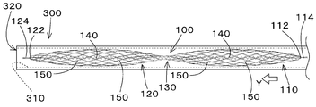
- 1 is an overall view (a coil spring 140 is in a contracted state) of a defect hole closing material 100 which is an example of a medical material according to the present invention.
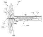
- 1 is an overall view (a coil spring 140 is in an intermediate state) of a defect hole closing material 100 which is an example of a medical material according to the present invention.
- FIG. 2B is a perspective view of FIG. 2A.
- 1 is an overall view (a coil spring 140 is in an expanded state) of a defect hole closing material 100 which is an example of a medical material according to the present invention.
- 1 is an overall view (a coil spring 140 is in a contracted state and an extended state) of a defect hole closing material 100 which is an example of a medical material according to the present invention.
- FIG. 2B is a partial side view of the defect hole closure 100 of FIG. 2A.
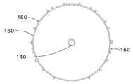
- FIG. 5A is a cross-sectional view taken along the line AA of FIG. 5A.
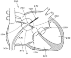
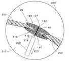
- It is a conceptual diagram in the case where the defect hole closing material 100 which is an example of the medical material which concerns on this invention is used for the catheter treatment of the atrial septal defect.
- It is an enlarged view (No. 1) of the part B of FIG. 6 which shows the procedure of catheter treatment.
- No. 2 of the part B of FIG. 6 which shows the procedure of catheter treatment.
- the medical material according to the present invention will be described in detail based on the drawings.
- a defect hole closing material used for catheter treatment will be described, but other openings or passages such as a ventricular septal defect, a heart with patent ductus arteriosus, etc. It is also suitable for closing other openings in the body and other areas of the body, such as an arteriovenous fistula (eg, the stomach) or for closing passages. Therefore, the defect hole closing material according to the embodiment of the present invention is not limited to the use for closing the hole of the atrial septal defect.
- the knitted tissue of the defect hole closing material (closure plug) 100 is described as knitting bioabsorbable fibers (an example of a wire), but the present invention is not limited to this. It's not a thing. Any defect hole closing material capable of performing a catheter treatment for closing a defect hole formed in a living body may be used, and the knitted tissue thereof has first to third characteristics described below, and has a first action to a third action. As long as it is a material that exerts its action, it may be knitted with a wire rod other than the bioabsorbable fiber. It is preferable that such a wire material has a certain degree of hardness in order to have shape retention (shape retention).
- FIG. 1 is an overall view of the defect hole closing material 100 according to the present embodiment (the coil spring 140 is in a contracted state), and FIGS. 2A and 2B are overall views of the defect hole closing material 100 (the coil spring 140 is in an intermediate state).
- FIG. 3 is an overall view of the defect hole closing material 100 (the coil spring 140 is in an expanded state)
- FIG. 4 is an overall view of the defect hole closing material 100 (the coil spring 140 is in a contracted state and an expanded state). Show. Note that FIG. 3 shows a state in which the entire defect hole closing material 100 is housed in the catheter 300, and FIG. 4 shows a state in which half of the defect hole closing material 100 (on the side of the first tubular portion 110) is housed in the catheter 300.
- the defect hole closing member 100 which is entirely housed inside (the space formed by the inner wall 310), is inserted from the first tubular portion 110 side to the second tubular portion 120 of the catheter 300.
- the state shown in FIG. 4 is obtained, and when the first tubular portion 110 is further pushed out in the direction Y indicated by an arrow, the state shown in FIG. 1 is obtained.
- the state of the defect hole closing material 100 shown in FIGS. 2A and 2B is a virtual state in which the coil spring 140 is an intermediate state between the contracted state and the extended state. Note that, in the following, when only FIG.
- the dotted line is a virtual line that shows the outline of the defect hole closing material 100 when the coil spring 140 is in the intermediate state
- the alternate long and short dash line is a line that virtually shows the coil spring 140.
- the defect hole closing material 100 is generally formed by a tubular body of a knitted structure using a wire rod, and the tubular diameter of the approximately central portion 130 of the tubular body is the other portion.
- the first tubular portion 110 on the first end 112 side in the longitudinal direction of the tubular body in the defect hole closing member 100 and the other end portions (first A second tubular portion 120 on the side of the end portion 122) of 2 is formed. It is characteristic that both ends are engaged with the wire rod 114 of the first end portion 112 and the wire rod 124 of the second end portion 122, respectively, and from the first end portion 112 side through the substantially central portion 130.
- the coil spring 140 which is an example of the elastic member passed through the inside of the first tubular portion 110 and the second tubular portion 120 up to the second end 122 side, is provided.
- the elastic member may be a member other than the coil spring 140 as long as it has elasticity and can exhibit the action described later by the elasticity, and is not limited to the coil spring 140.
- FIG. 5A shows a partial side view of the defect hole closing material 100
- FIG. 5B shows a sectional view taken along the line AA of FIG. 5A.
- FIG. 5B is a cross-sectional view of the defect hole closing material 100, only the cross-sections of the coil spring 140, the bioabsorbable fiber 150 and the porous tubular layer 160 are shown, and the living body can be seen from the direction of the arrow A.
- the stitches of the absorbent fiber 150 are not shown.
- the porous tubular layer 160 is illustrated as a transparent material. ..
- this defect hole closing material 100 has two tubular bodies (a first tubular portion 110 and a second tubular portion 120) of a knitted tissue using a bioabsorbable material. ), the shape of which is composed of such two cylinders, for example, an hourglass shape, a figure eight shape, a double spindle shape (a slender rod-shaped object with a thick center and thin ends). It has a shape called two continuous shapes) or a peanut type (an external shape of a peanut shell containing two grains).
- the defective hole closing material 100 having such a shape has a shape in which the substantially central portion 130 is narrowed so that the tubular diameter of the approximately central portion 130 of the tubular body is smaller than the tubular diameters of the other portions. That is, the first tubular portion 110 on the first end 112 side and the second tubular portion 120 on the second end 122 side are formed around the substantially central portion 130.
- the defect hole closing member 100 is configured such that the first tubular portion 110 and the second tubular portion 110 have a shape such that the tubular diameter of the substantially central portion 130 is smaller than the tubular diameters of the other portions.
- the tubular portion 120 is integrally knitted, and the defect hole closing member 100 is formed into an hourglass shape, an 8-shaped shape, a double spindle type or a peanut type, which is composed of two cylindrical bodies.
- the defect hole closing member 100 is formed into an hourglass shape, an 8-shaped shape, a double spindle type or a peanut type, which is composed of two cylindrical bodies.
- an hourglass type a figure eight type, a double spindle type or a peanut type frame (three-dimensional pattern)
- one bioabsorbable fiber 150 is fitted to the frame.
- the entire shape of the defect hole closing material 100 is formed.
- the defective hole closing material 100 is substantially formed after the first tubular portion 110 and the second tubular portion 120 are integrally knitted to knit a tubular body having substantially the same diameter.
- the tubular diameter of the approximately central portion 130 is made smaller than the tubular diameter of the other portion, and then the binding of the approximately central portion 130 is released or heat is applied.
- the set is opened to form a substantially central portion 130 in which the tubular diameter of the central portion 130 is larger than the diameter of the coil spring 140, and the defective hole closing member 100 is configured by two tubular bodies as a whole. It may be formed into an hourglass shape, a figure eight shape, a double spindle shape or a peanut shape.
- the defect hole closing member 100 which is wholly housed inside the catheter 300 (the space formed by the inner wall 310) shown in FIG.
- the second tubular portion 120 is pushed out from the first tubular portion 110 side through the opening 320 of the catheter 300 in the Y direction shown by the arrow, the second tubular portion 120 is released from the space formed by the inner wall 310 of the catheter 300 and
- the coil spring 140 of the second tubular portion 120 contracts into the state of FIG. 4 and the first tubular portion 110 is further pushed out in the Y direction shown by the arrow, the first tubular portion 110 is formed by the inner wall 310 of the catheter 300. It is possible to realize a change in shape in which the coil spring 140 of the first tubular portion 110 contracts to be in the state shown in FIG. 1 after being released from the space to be formed.
- the defect hole closing member 100 has one end engaged with the first end 112 (for example, hooked in a loop of the wire rod 114 of the first end 112) and the other end having the second end.
- the first portion 112 is engaged with the portion 122 (for example, hooked in the loop of the wire rod 124 of the second end portion 122 ), and extends from the first end portion 112 side to the second end portion 122 side through the substantially central portion 130.
- a coil spring 140 passed through the inside of the cylinder portion 110 and the second cylinder portion 120 is provided.
- the loop-shaped wire rod 114 and wire rod 124 are formed of the bioabsorbable fiber 150.
- the first end portion 112 and the second end portion approach each other with the substantially central portion 130 as the center, and other than the substantially central portion 130.
- the cylinder diameters of the first cylinder portion 110 and the second cylinder portion 120, which are other portions, are expanded.
- the first tubular portion which is a portion other than the substantially central portion 130 up to a size corresponding to the defect hole closed by the defect hole closing member 100.
- the cylinder diameters of 110 and the second cylinder portion 120 are expanded.
- the first end 112 and the second end 122 are formed.
- the diameters of the first tubular portion 110 and the second tubular portion 120, which are other portions, are reduced by separating the catheter portion 130 from the center.
- the first tubular portion 110 and the second tubular portion which are other portions up to a size corresponding to the catheter 300 in which the defect hole closing material 100 is housed.
- the tube diameter of 120 is reduced.
- the first end 112 in the longitudinal direction of the tubular body of the defective hole closing material 100 and the second end which is the other end thereof. Can be moved closer to or further from the end 122 of the.
- the coil spring 140 When the coil spring 140 is in the contracted state, as shown in FIG. 1, the first end portion 112 and the second end portion 122 come close to each other, and the cylindrical diameter of the other portion of the substantially central portion 130 (first When the coil diameter of the barrel portion of the tubular portion 110 and the second tubular portion 120 is expanded, and the coil spring 140 is in the extended state, as shown in FIG. 3, the first end portion 112 and the second end portion 122 are formed.
- the cylinder diameter of the other portion of the substantially central portion 130 (the cylinder diameter of the body portion in the first cylinder portion 110 and the second cylinder portion 120) is reduced. Furthermore, as shown in FIG. 4, when the second tubular portion 120 is pushed out from the catheter 300 in the Y direction shown by the arrow, the shape of the second tubular portion 120 whose shape is regulated by the inner wall 310 of the catheter 300 is changed freely. As a result, only the portion of the coil spring 140 contained in the second tubular portion 120 contracts, and only the tubular diameter of the body portion in the second tubular portion 120 is expanded.
- the shape of the first tubular portion 110 whose shape is regulated by the inner wall 310 of the catheter 300 can be freely changed, and the coil spring 140
- the portion included in the first tubular portion 110 is also contracted, and the tubular diameter of the body portion in the first tubular portion 110 is also expanded as shown in FIG.
- the defect hole closing material 100 is provided with an X-ray opaque material that reacts to X-ray imaging in the first tubular portion 110, the second tubular portion 120, and the substantially central portion 130.
- the method of providing the X-ray opaque material on the first tubular portion 110, the second tubular portion 120, and the substantially central portion 130 is not particularly limited. ..
- another member having a radiopaque property a gold chip, a platinum chip, or the like
- barium sulfate or the like having a radiopaque property is applied. There are things to do.
- the X-ray opaque material 110A is provided substantially at the center of the first tubular portion 110 in the longitudinal direction of the tubular body (in the vicinity of the portion having the maximum diameter), and the approximately central portion of the second tubular portion 120 in the longitudinal direction of the tubular body (
- the X-ray opaque material 120A is provided in the vicinity of the maximum diameter portion
- the X-ray opaque material 130A is provided in the substantially central portion 130.
- the number of X-ray opaque materials at each position and their positional relationship are not limited, but apart from the substantially central portion 130, they are separated in the circumferential direction of the cylindrical body (for example, at intervals of approximately 90 degrees).
- the central portion 130 is provided at four locations, and the substantially central portion 130 is provided at two locations less than that because the length in the longitudinal direction of the cylinder is short and the diameter is small.
- the reason (one example) of providing two or more X-ray opaque materials at each location is that the function and effect to be described later are exhibited even if one is removed, and the reason for providing them in a circumferential direction ( As an example), it is possible to prevent the visibility from being deteriorated because the image is solidified at the time of X-ray imaging unless it is provided at a distance.
- the part 120 and the part 120 approach each other with the center part 130 (defective hole 252) as the center, and the tube diameter of the first tube portion 110 and the tube diameter of the second tube portion 120 are expanded, and finally,
- the atrial septum 250 should be sandwiched from both sides by the first tubular portion 110 and the second tubular portion 120, and the defective hole 252 opened in the atrial septum 250 should be closed by the defective hole closing material 100. That is, if both the second tubular portion 120 and the first tubular portion 110 are expanded in diameter on the left atrium side or the right atrium side, the defect hole closing member 100 causes the defect hole 252 opened in the atrial septum 250 to be formed. It falls into a situation that cannot be closed.
- an X-ray fluoroscopic image is obtained by X-raying a region including the defect hole closing material 100.
- the ray opaque material 110A, the X-ray opaque material 120A, and the X-ray opaque material 130A are visually checked.
- (1) the expanded state of the first tubular portion 110, (2) the expanded state of the second tubular portion 120, and (3) only the second tubular portion 120 is expanded (the first tubular portion 110 is It is possible to visually confirm to what extent the defect hole closing material 100 should be extruded from the catheter 300 with an applicator or the like in order to prevent expansion.
- an X-ray opaque material that reacts to X-ray imaging is provided in the substantially central portion 130. Since 130A is provided, it is possible to visually confirm the degree of extrusion of the defect hole closure material 100 from the catheter 300 for expanding only the second tubular portion 120 (not expanding the first tubular portion 110). ..
- the second tubular portion 120 in the left atrium is expanded while visually confirming the pushing condition of the defect hole closing material 100 from the catheter 300, and then the first tubular portion 110 in the right atrium.
- the atrial septum 250 is sandwiched from both sides by the first tubular portion 110 and the second tubular portion 120, and the defective hole 252 opened in the atrial septum 250 is closed by the defective hole closing material 100. it can.
- a porous tubular layer 160 composed of any of a nonwoven fabric made of a bioabsorbable material, a sponge, a film, and a composite thereof is arranged on the inner surface of the tubular body.
- the first tubular portion 110 and the second tubular portion 120 are composed of a woven fabric (coarse fabric) of the bioabsorbable fiber 150, a knitted fabric, a braided woven fabric, or a tubular knitted fabric, and the entire knitted fabric is knitted. It is considered to be a tissue.
- this knitting structure is not limited to knitting formed by knitting, and as described above, a knitting structure is formed by a coarse weave structure such as a screen door. including.
- the porous tubular layer 160 is composed of a non-woven fabric, a sponge, a film, or a composite thereof in order to hold the drug by coating, impregnation, embedding, or the like. Furthermore, the porous tubular layer 160 is not limited to a bioabsorbable material, and may be a material that is not absorbed by the living body.
- the first tubular portion 110, the second tubular portion 120, and the porous tubular layer 160 are all made of a bioabsorbable material.
- the entire defect hole closing material 100 excluding the spring 140 is bioabsorbable. Further, although the treatment for closing the defect hole is performed by changing the shape of the defect hole closing material 100, even if the shape of the defect hole closing material 100 changes in the living body, the tissue in the living body is changed.
- the defect hole closing material 100 is formed of a material, a stitch shape, a fiber structure and a fiber cross section that are not damaged.
- the coil spring 140 is usually made of, for example, a nickel-titanium alloy and is not bioabsorbable, but a magnesium-based alloy described later may be used to make it bioabsorbable.
- a bioabsorbable alloy for the coil spring 140 is advantageous in that it responds to X-ray imaging, and the use of an alloy without bioabsorbability results in no metal member remaining in the body for life. It is advantageous in that it does not cause the problem of concern about problems in the remote period.
- the coil spring 140 of the defect hole closing member 100 is made of a material that does not react to X-ray imaging.
- the bioabsorbable fiber 150 constituting the first tubular portion 110 and the second tubular portion 120 is, for example, polyglycolic acid, polylactide (D, L, DL polymer), polycaprolactone, glycolic acid-lactide (D). , L, DL polymer), glycolic acid- ⁇ -caprolactone copolymer, lactide (D, L, DL polymer) - ⁇ -caprolactone copolymer, poly (p-dioxanone), glycolic acid-lactide (D) , L, DL)- ⁇ -caprolactone copolymer, etc., and is used in the form of being processed into any of monofilament yarn, multifilament yarn, twisted yarn, braid, etc. It is preferably used in the form of
- the material of the bioabsorbable fiber 150 may be a biodegradable alloy.
- An example of such a biodegradable alloy is an alloy based on magnesium as a raw material.
- the diameter of the bioabsorbable fiber 150 is about 0.001 mm to 1.5 mm, and the fiber diameter and type suitable for the catheter treatment to be applied are selected.
- the cross section of the bioabsorbable fiber 150 may be any of a circle, an ellipse, and other irregular shapes (for example, a star shape), provided that the tissue in the living body is not damaged.
- the surface of the bioabsorbable fiber 150 may be hydrophilized by plasma discharge, electron beam treatment, corona discharge, ultraviolet irradiation, ozone treatment, or the like.
- a plurality of bioabsorbable fibers 150 are provided around a silicone rubber tube (not shown) having an outer diameter desired as a monofilament thread, for example.
- a braided machine having 12 yarn feeders is used to fabricate a braided woven fabric, or a circular knitting machine (not shown) is used to knit into a knitted structure of a tubular body having substantially the same diameter.
- an hourglass shape which is composed of two cylinders, is squeezed in the substantially central portion 130 by a string made of the same material as the first cylinder part 110 and the second cylinder part 120, and is in the shape of a figure eight.
- the mold is formed into a double spindle type or a peanut type.
- the tubular diameters of the first tubular portion 110 and the second tubular portion 120 are smaller than the inner diameter of the catheter when the diameter is reduced, and have a size suitable for catheter treatment of atrial septal defect when the diameter is increased. ..
- the cylinder diameters of the first cylinder portion 110 and the second cylinder portion 120 are about 5 mm to 80 mm, preferably about 15 mm to 25 mm.
- the lengths of the first tubular portion 110 and the second tubular portion 120, and the density of the knitted tissue of the defect hole closing material 100 are also suitable for catheter treatment of atrial septal defect.
- the tube diameter and length of the first tubular portion 110 and the second tubular portion 120 do not have to be the same, and may be changed to be suitable for catheter treatment of atrial septal defect.
- the bioabsorbable material constituting the porous tubular layer 160 is not particularly limited, and for example, polyglycolic acid, polylactide (D, L, DL form), polycaprolactone, glycolic acid-lactide (D, L, DL form). ) Copolymer, glycolic acid- ⁇ -caprolactone copolymer, lactide (D, L, DL form) - ⁇ -caprolactone copolymer, poly (p-dioxanone), glycolic acid-lactide (D, L, DL form) )- ⁇ -Caprolactone copolymer and other synthetic absorbent polymers can be mentioned. These may be used alone or in combination of two or more.
- polyglycolic acid, lactide (D, L, DL form) - ⁇ -caprolactone copolymer, glycolic acid- ⁇ -caprolactone copolymer and glycolic acid-lactide (D, Lactide) show appropriate decomposition behavior.
- At least one selected from the group consisting of L, DL form) - ⁇ -caprolactone copolymer is suitable and is composed of any of non-woven fabric, sponge, film or a composite thereof.
- a non-woven fabric can be exemplified.
- the material of the porous tubular layer 160 may be a biodegradable alloy.
- An example of such a biodegradable alloy is an alloy based on magnesium as a raw material.
- the hydrophilization treatment is not particularly limited, and examples thereof include plasma treatment, glow discharge treatment, corona discharge treatment, ozone treatment, surface graft treatment, and ultraviolet irradiation treatment. Among them, the plasma treatment is preferable because the water absorption rate can be dramatically improved without changing the appearance of the nonwoven fabric layer.
- the porous tubular layer 160 may be a sponge layer or a film layer, or a composite layer of a nonwoven fabric and a sponge layer, a composite layer of a nonwoven fabric and a film layer, a composite layer of a sponge layer and a film layer, and a nonwoven fabric. It may be a composite layer of a sponge layer and a film layer.
- the porous tubular layer 160 holds a drug suitable for catheter treatment of atrial septal defect.
- the defect hole closing material 100 has the following features.
- First characteristic An hourglass type, an 8-shaped type, a double spindle type or a peanut type composed of a first tubular portion 110 and a second tubular portion 120 narrowed in a substantially central portion 130. ing.
- Second feature One end is engaged with the first end 112 (hooked on the loop-shaped wire 114 of the first end 112), and the other end is engaged with the second end 122 (second feature).
- a coil spring 140 passed through the inside of the portion 120 is provided. (Third feature) It is composed of a first tubular portion 110, a second tubular portion 120, a coil spring 140 (when formed of an alloy based on magnesium), and a porous tubular layer 160. All materials are made of bioabsorbable material (the coil spring 140 does not necessarily have to be bioabsorbable).
- the shape is regulated by the inner wall 310 of the catheter 300.
- the second tubular portion 120 that has been formed can freely change its shape, and only a portion of the entire coil spring 140 that is included in the second tubular portion 120 contracts to cause a trunk portion of the second tubular portion 120.
- this defect hole closing material 100 is suitable for catheter treatment of atrial septal defect because it exhibits the following effects.
- the cylinder diameter of the defect hole closing material 100 can be made smaller than the inner diameter of the catheter 300 and set in the catheter 300.
- the catheter 300 is set and fed to the position of the hole opened in the atrial septum, and the first end 112 is pushed by an applicator or the like in the living body to push the second tubular portion 120 to the catheter 300.
- the coil spring 140 of the second tubular portion 120 contracts to expand the tubular diameter of the body portion of the second tubular portion 120, and further pushes the first end 112 with an applicator or the like.
- the coil spring 140 of the first tubular portion 110 is also contracted, and the tubular diameter of the body portion of the first tubular portion 110 is also expanded to the right atrium.
- the arranged first cylinder part 110 and the second cylinder part 120 arranged on the left atrium side can approach each other around the substantially central part 130 to close the hole opened in the atrial septum.
- defect hole closing material 100 Since all the materials (sometimes excluding the coil spring 140) forming the defect hole closing material 100 are bioabsorbable materials, they are finally absorbed in the living body, so that they are defective in the remote period. There is almost no possibility of. In order to easily understand such an action, a case where the defect hole closing material 100 is used for catheter treatment of atrial septal defect will be described with reference to FIGS. 6 to 9.
- FIG. 6 is a conceptual diagram when the defect hole closing material 100 is used for catheter treatment of an atrial septal defect
- FIGS. 7 to 9 are enlarged views of a portion B of FIG. 6 showing procedures of the catheter treatment, respectively. Show.
- only items specific to the usage of the defect hole closure material 100 according to the present embodiment will be described, and general items are the same as the known catheter treatment for atrial septal defect. Since there is, I will not repeat the detailed explanation here.
- a human heart 200 is connected to the superior vena cava and inferior vena cava to receive venous blood from the whole body, and is connected to the right atrium 210 via the pulmonary artery and the tricuspid valve 260 to the lungs.
- Right ventricle 220 that pumps venous blood
- left ventricle 230 that is connected to the pulmonary vein and receives arterial blood from the lung
- left ventricle 240 that is connected to the left ventricle 230 via the aorta and mitral valve 270 and pumps arterial blood throughout the body. It is composed of ventricles.
- Atrial septal defect is a disease in which a defect hole 252 is opened in the atrial septum 250 that separates the right atrium 210 and the left atrium 230.
- the distal end side of the catheter 300 is shown by a virtual line
- the defect hole closing material 100 housed in the catheter 300 is shown by a solid line.
- the entire coil spring 140 is pulled by pulling in a direction in which the first end 112 and the second end 122 of the defect hole closing material 100 that expand to the appropriate size with respect to the defect hole 252 are separated. Are stretched to make the tubular diameter of the defect hole closing material 100 smaller than the inner diameter of the catheter 300, and then set in the catheter 300. Insert the catheter 300 accommodating the defect hole closure material 100 from the femoral vein (see FIG. 3), move the catheter 300 in the direction of the arrow X(1), and from the right atrium 210 side to the left through the defect hole 252. The catheter 300 containing the defect hole closing material 100 is brought closer to the atrium 230 side.
- the catheter 300 accommodating the defect hole closing material 100 is stopped at a position where the substantially central portion 130 of the defect hole closing material 100 corresponds to the vicinity of the defect hole 252.
- the shape of the second tubular portion 120 whose shape is regulated by the inner wall 310 of the catheter 300 can be freely changed.
- the coil spring 140 only the portion enclosed by the second tubular portion 120 contracts, and only the tubular diameter of the body portion of the second tubular portion 120 expands as shown in FIG.
- the second tubular portion 120 is applied from the catheter 300 until the X-ray opaque material 130A comes near the exit of the catheter 300. You can push it out in the Y direction indicated by the arrow.
- the shape of the first tubular portion 110 whose shape is regulated by the inner wall 310 of the catheter 300 can be freely changed.
- the portion of the coil spring 140 contained in the first tubular portion 110 also contracts, and the tubular diameter of the body portion in the first tubular portion 110 is also expanded as shown in FIG. That is, when the defect hole closure material 100 is pushed out from the catheter 300 with an applicator or the like, the second tubular portion 120 disposed on the left atrium side expands first, and then the first tubular portion 120 disposed on the right atrium side.
- the barrel 110 expands later.
- the first tubular portion 110 disposed on the right atrium side and the second tubular portion 120 disposed on the left atrium side approach each other with the substantially central portion 130 (defective hole 252) as the center, and The tubular diameter of the first tubular portion 110 and the tubular diameter of the second tubular portion 120 expand.
- the atrial septum 250 is sandwiched from both sides by the first tubular portion 110 and the second tubular portion 120, and the atrial septum 250 is opened by the defect hole closure material 100.
- the defect hole 252 can be closed.
- a defect hole closing material 100 (may exclude the coil spring 140) made entirely of a bioabsorbable material is placed in the living body (to be exact, in the vicinity of the defect hole 252). Since the material of the defect hole closing material 100 left in the living body in this way is all bioabsorbable material (the coil spring 140 may be excluded), it is finally absorbed in the living body, so that it is a malfunction in the remote period. There is almost no possibility of.
- the coil spring 140 is not provided, it is necessary to fix the defect hole closing material 100 in the form shown in FIG. 9 before placing the defect hole closing material 100 in the living body. It has been considered that the bioabsorbable fiber 150 is heat-set in a living body while the heat-adhesive fiber 150 is provided. However, the defect hole closing material 100 is advantageous because the form of the defect hole closing material 100 can be fixed to the form shown in FIG. 9 by the coil spring 140.
- the defect hole closing material 100 As described above, according to the defect hole closing material 100 according to the present embodiment, all of it is made of the bioabsorbable material (the coil spring 140 may be excluded) and is finally absorbed in the body. Therefore, there is almost no possibility of a malfunction in the remote period. Moreover, since the tubular diameter of the defective hole closing material 100 is easily changed by providing the coil spring 140, the tubular diameter of the defective hole closing material 100 can be finely changed and easily set in the catheter. Further, by providing the coil spring 140 at the position of the defect hole by simply pushing out the defect hole closure material 100 from the catheter 300, the diameter of the defect hole closure material 100 can be increased and the two cylinders can easily approach each other. The shape of the defect can be easily changed, and the defect can be easily fixed to close the defect hole opened in the atrial septum.
- the present invention is suitable for a medical material to be set in a catheter for treating a defect hole formed in a living tissue, and can be released and placed at a treatment site to enable a minimally invasive treatment and a medical material. It is particularly preferable because even if it remains in the body, there is almost no possibility of a malfunction in the remote period.
Landscapes
- Health & Medical Sciences (AREA)
- Surgery (AREA)
- Life Sciences & Earth Sciences (AREA)
- Biomedical Technology (AREA)
- Nuclear Medicine, Radiotherapy & Molecular Imaging (AREA)
- Engineering & Computer Science (AREA)
- Cardiology (AREA)
- Heart & Thoracic Surgery (AREA)
- Medical Informatics (AREA)
- Molecular Biology (AREA)
- Animal Behavior & Ethology (AREA)
- General Health & Medical Sciences (AREA)
- Public Health (AREA)
- Veterinary Medicine (AREA)
- Surgical Instruments (AREA)
Abstract
心房中隔欠損症に対して、遠隔期の不具合の可能性がほとんどない、低侵襲の治療を実現する欠損孔閉鎖材を提供する。 欠損孔閉鎖材(100)は、生体吸収性材料の編み目状組織の2つの筒体(第1の筒部(110)および第2の筒部(120))ならびにそれらの間の略中央部(130)により形成され、第1の筒部(110)にX線不透過材(110A)、第2の筒部(120)にX線不透過材(120A)、略中央部(130)にX線不透過材(130A)をそれぞれ備える。欠損孔閉鎖材(100)を心房中隔欠損症のカテーテル治療において欠損孔閉鎖材(100)を含む部位をレントゲン撮像したX線透視画像に写ったX線不透過材(130A)の位置まで欠損孔閉鎖材(100)をカテーテルから押し出すと、第1の筒部(110)の筒径が拡張されないで第2の筒部(120)の筒径だけが拡張される。
Description
本発明は、生体組織に形成された欠損孔を治療するための医療用材料に関し、特に、カテーテルにセットされて血管内を通じて治療部位まで送り込まれて生体内に留置される医療用材料に関する。
人間の心臓は中隔という組織で左右の部屋が仕切られており、左右それぞれに心房と心室とがあり、右心房、右心室、左心房、左心室の2心房2心室で構成されている。このような構成の心臓において、胎児期の発達障害により、先天的に欠損孔と呼ばれる穴が、右心房と左心房とを隔てる心房中隔に開いている心房中隔欠損症(ASD:Atrial Septal Defect)という疾患がある。
この心房中隔欠損症の治療としては、以下に示す2つの方法がある。ひとつは胸を切って行う外科手術、もうひとつが胸を切らずに、閉鎖栓を使ったカテーテル治療である。
外科手術(パッチ手術)は、人工心肺を使用し、開胸して、欠損孔をパッチにて閉じる。カテーテル治療は、カテーテルに閉鎖栓をセットし、カテーテルを血管内に挿入し、目的の位置(欠損孔)まで送り込んで、その後、閉鎖栓を放出し体内に留置する。このカテーテル治療では胸を切開しないで足の付け根の静脈(大腿静脈)から、細長く折り畳んだ閉鎖栓とよばれる小さな治具(デバイス)を心房中隔に開いた穴の位置まで送り込み、穴を塞ぐものである。このカテーテル治療の長所は、全身麻酔が必要な開胸手術をすることなく、足の付け根(そけい部)という目立たない場所から、ごく小さな皮膚の切開(数ミリ)で治療ができる点である。
外科手術(パッチ手術)は、人工心肺を使用し、開胸して、欠損孔をパッチにて閉じる。カテーテル治療は、カテーテルに閉鎖栓をセットし、カテーテルを血管内に挿入し、目的の位置(欠損孔)まで送り込んで、その後、閉鎖栓を放出し体内に留置する。このカテーテル治療では胸を切開しないで足の付け根の静脈(大腿静脈)から、細長く折り畳んだ閉鎖栓とよばれる小さな治具(デバイス)を心房中隔に開いた穴の位置まで送り込み、穴を塞ぐものである。このカテーテル治療の長所は、全身麻酔が必要な開胸手術をすることなく、足の付け根(そけい部)という目立たない場所から、ごく小さな皮膚の切開(数ミリ)で治療ができる点である。
特表2008-512139号公報(特許文献1)は、心房中隔欠損症のカテーテル治療に用いられるアセンブリ(閉鎖栓)を開示する。このアセンブリは、心臓の通路(欠損孔)を密閉する。このアセンブリは、通路の第一端の近位に配置するために使用される第一アンカー、通路の第二端の近位に配置するために使用される第二アンカー、および通路を通って伸び、第一および第二アンカーに結合するために使用される可撓性延長材を含む心臓の通路を密閉する閉鎖装置からなり、第二アンカーは可撓性延長材に対して移動可能で第一および第二アンカーの間の可撓性延長材の長さを変更し、閉鎖装置を心臓の通路に供給する供給システムからなり、供給装置はガイドカテーテルの内腔の中を移動するように設定され、第二アンカーの可撓性延長材に沿った運動を制御するワイヤーを含む。
そして、この特許文献1において、卵円孔開存(PFO:Patent Foramen Oval)閉鎖装置(閉鎖栓)は、左心房アンカー、右心房アンカー、テザーおよびロックを含み、左心房アンカー、テザーを介して左心房アンカーに結合する右心房アンカーおよびロックは心臓内に残留してPFOを密閉することが開示されている。
パッチ手術の場合には、人工心肺を使用し、また、侵襲性が高いため入院期間が長くなるという問題がある。カテーテル治療の場合には、人工心肺は使用せず、また、侵襲性も低いため入院期間も短く好ましい。
特許文献1に開示されるように、左心房アンカーおよび右心房アンカーは心臓内に残留する。そして、左心房アンカーおよび右心房アンカーは一つまたはそれ以上のアームを含み、アームはハブから放射状に外側に向かって伸びており、このアームは好適には二成分ニッケルチタン合金の圧延シートから形成されている。そして、これらの左心房アンカーおよび右心房アンカーを生体内で拡張させて欠損孔を塞ぐことになるが、アンカーの拡張を開始させると、容易には元に戻すことはできない。特許文献1に開示されているような、複雑な構造で、かつ、生体外からの操作が難しい、専用の取出し装置を用いてアンカーを折りたたむことになる。
特許文献1に開示されるように、左心房アンカーおよび右心房アンカーは心臓内に残留する。そして、左心房アンカーおよび右心房アンカーは一つまたはそれ以上のアームを含み、アームはハブから放射状に外側に向かって伸びており、このアームは好適には二成分ニッケルチタン合金の圧延シートから形成されている。そして、これらの左心房アンカーおよび右心房アンカーを生体内で拡張させて欠損孔を塞ぐことになるが、アンカーの拡張を開始させると、容易には元に戻すことはできない。特許文献1に開示されているような、複雑な構造で、かつ、生体外からの操作が難しい、専用の取出し装置を用いてアンカーを折りたたむことになる。
しかしながら、たとえば、アンカーが心房内の生体組織に引っ掛かり傷付ける等の事態になった場合には、このような専用の取出し装置でアンカーを折りたたむだけの時間的余裕がない場合もある。このような場合には、開胸手術に即座に切り換えざるを得ない。これでは、結局、侵襲性が高い開胸手術を受けることになるという問題点がある。
さらに、金属製の欠損孔閉鎖栓が体内に一生涯残存するため、遠隔期の不具合が懸念されるという問題点がある。
さらに、金属製の欠損孔閉鎖栓が体内に一生涯残存するため、遠隔期の不具合が懸念されるという問題点がある。
本発明は、従来技術の上記の問題点に鑑みて開発されたものであり、その目的とするところは、生体内の治療部位にて放出・留置できる低侵襲のカテーテル治療を、複雑な構造を備えず容易な操作で可能となり、体内に残存しても遠隔期の不具合の可能性がほとんどない、医療用材料を提供することを目的とする。
上記目的を達成するため、本発明に係る医療用材料は以下の技術的手段を講じている。
すなわち、本発明に係る医療用材料は、線材を用いた編み目状組織の筒体により形成された医療用材料であって、前記筒体の略中央部の筒径が他の部分の筒径よりも小さい形状を備え、前記略中央部を中心にして前記医療用材料における筒体長手方向の第1の端部側の第1の筒部と他の端部側の第2の筒部とが形成され、前記第1の筒部および前記第2の筒部ならびに前記略中央部にX線不透過材を備えることを特徴とする。
すなわち、本発明に係る医療用材料は、線材を用いた編み目状組織の筒体により形成された医療用材料であって、前記筒体の略中央部の筒径が他の部分の筒径よりも小さい形状を備え、前記略中央部を中心にして前記医療用材料における筒体長手方向の第1の端部側の第1の筒部と他の端部側の第2の筒部とが形成され、前記第1の筒部および前記第2の筒部ならびに前記略中央部にX線不透過材を備えることを特徴とする。
好ましくは、前記第1の端部の線材と前記第2の端部の線材とにそれぞれ両端が係合され、前記第1の端部側から前記略中央部を介して前記第2の端部側まで前記第1の筒部および前記第2の筒部の内部に通された弾性部材を備えるように構成することができる。
さらに好ましくは、前記弾性部材が収縮状態であるときに、前記第1の端部と前記第2の端部とが前記略中央部を中心にして接近して、前記他の部分の筒径が拡張されるように構成することができる。
さらに好ましくは、前記弾性部材が収縮状態であるときに、前記第1の端部と前記第2の端部とが前記略中央部を中心にして接近して、前記他の部分の筒径が拡張されるように構成することができる。
さらに好ましくは、前記弾性部材が収縮状態であるときに、前記医療用材料により閉鎖される欠損孔に対応した大きさまで前記他の部分の筒径が拡張されるように構成することができる。
さらに好ましくは、前記弾性部材が伸張状態であるときに、前記第1の端部と前記第2の端部とが前記略中央部を中心にして離隔して、前記他の部分の筒径が縮小されるように構成することができる。
さらに好ましくは、前記弾性部材が伸張状態であるときに、前記第1の端部と前記第2の端部とが前記略中央部を中心にして離隔して、前記他の部分の筒径が縮小されるように構成することができる。
さらに好ましくは、前記弾性部材が伸張状態であるときに、前記医療用材料が収納されるカテーテルに対応した大きさまで前記他の部分の筒径が縮小されるように構成することができる。
さらに好ましくは、前記弾性部材は、前記略中央部の筒径よりも直径が小さいコイルばねであるように構成することができる。
さらに好ましくは、前記弾性部材は、前記略中央部の筒径よりも直径が小さいコイルばねであるように構成することができる。
さらに好ましくは、前記形状は、砂時計型、8の字型または2連の紡錘型であるように構成することができる。
さらに好ましくは、前記線材は、生体吸収性材料であるように構成することができる。
さらに好ましくは、生体吸収性材料からなる不織布、スポンジ、フィルムおよびこれらの複合体のいずれかから構成された多孔質筒状層が、前記筒体の内面に配置されているように構成することができる。
さらに好ましくは、前記線材は、生体吸収性材料であるように構成することができる。
さらに好ましくは、生体吸収性材料からなる不織布、スポンジ、フィルムおよびこれらの複合体のいずれかから構成された多孔質筒状層が、前記筒体の内面に配置されているように構成することができる。
本発明の医療用材料によれば、生体内の治療部位にて放出・留置できる低侵襲のカテーテル治療を、複雑な構造を備えず容易な操作で可能となる。さらに、本発明の医療用材料によれば、体内に残存しても遠隔期の不具合の可能性がほとんどない。
以下、本発明に係る医療用材料を、図面に基づき詳しく説明する。なお、以下においては、本発明に係る医療用材料の一例として、カテーテル治療に用いられる欠損孔閉鎖材について説明するが、その他の開口または通路、たとえば心室中隔欠損、動脈管開存等の心臓のその他の開口、および動静脈瘻等の生体のその他の部位(たとえば胃)の開口または通路の閉鎖にも適している。従って、本発明の実施の形態に係る欠損孔閉鎖材は、心房中隔欠損症の穴を閉鎖するための使用に限定されるものではない。
さらに、以下の実施の形態においては、欠損孔閉鎖材(閉鎖栓)100の編み目状組織は生体吸収性繊維(線材の一例)を編成したものとして説明するが、本発明はこれに限定されるものではない。生体に形成された欠損孔を閉鎖するカテーテル治療ができる欠損孔閉鎖材であればよく、その編み目状組織は、後述する第1の特徴~第3の特徴を備え第1の作用~第3の作用を発現する素材であれば生体吸収性繊維以外の線材で編成されていても構わない。このような線材としては、形態保持性(形状保持性)を備えるためにある程度の硬度を備えることが好ましい。
[構成]
図1に本実施の形態に係る欠損孔閉鎖材100の全体図(コイルばね140が収縮状態)を、図2Aおよび図2Bにこの欠損孔閉鎖材100の全体図(コイルばね140が中間状態)を、図3にこの欠損孔閉鎖材100の全体図(コイルばね140が伸張状態)を、図4にこの欠損孔閉鎖材100の全体図(コイルばね140が収縮状態および伸張状態)を、それぞれ示す。なお、図3はこの欠損孔閉鎖材100の全体がカテーテル300に収納されている状態を、図4はこの欠損孔閉鎖材100の半分(第1の筒部110側)がカテーテル300に収納されている状態を、それぞれ示す図である。図3に示すカテーテル300の内部(内壁310により形成される空間)にその全体が収納されている欠損孔閉鎖材100を、第1の筒部110側から第2の筒部120をカテーテル300の開口部320から矢示Y方向に押し出すと図4の状態になって、さらに第1の筒部110を矢示Y方向に押し出すと図1の状態になる。ここで、図2Aおよび図2Bに示す欠損孔閉鎖材100の状態は、コイルばね140が収縮状態と伸張状態との中間状態であって仮想的な状態である。なお、以下において、図2としか記載していない場合には基本的には図2Aを意味する。また、図2Bにおいて、点線はコイルばね140が中間状態であるときの欠損孔閉鎖材100の略外形を示す仮想線であって、一点鎖線はコイルばね140を仮想的に示す線である。
図1に本実施の形態に係る欠損孔閉鎖材100の全体図(コイルばね140が収縮状態)を、図2Aおよび図2Bにこの欠損孔閉鎖材100の全体図(コイルばね140が中間状態)を、図3にこの欠損孔閉鎖材100の全体図(コイルばね140が伸張状態)を、図4にこの欠損孔閉鎖材100の全体図(コイルばね140が収縮状態および伸張状態)を、それぞれ示す。なお、図3はこの欠損孔閉鎖材100の全体がカテーテル300に収納されている状態を、図4はこの欠損孔閉鎖材100の半分(第1の筒部110側)がカテーテル300に収納されている状態を、それぞれ示す図である。図3に示すカテーテル300の内部(内壁310により形成される空間)にその全体が収納されている欠損孔閉鎖材100を、第1の筒部110側から第2の筒部120をカテーテル300の開口部320から矢示Y方向に押し出すと図4の状態になって、さらに第1の筒部110を矢示Y方向に押し出すと図1の状態になる。ここで、図2Aおよび図2Bに示す欠損孔閉鎖材100の状態は、コイルばね140が収縮状態と伸張状態との中間状態であって仮想的な状態である。なお、以下において、図2としか記載していない場合には基本的には図2Aを意味する。また、図2Bにおいて、点線はコイルばね140が中間状態であるときの欠損孔閉鎖材100の略外形を示す仮想線であって、一点鎖線はコイルばね140を仮想的に示す線である。
これらの図に示すように、この欠損孔閉鎖材100は、大略的には、線材を用いた編み目状組織の筒体により形成され、この筒体の略中央部130の筒径が他の部分の筒径よりも小さい形状を備え、略中央部130を中心にして欠損孔閉鎖材100における筒体長手方向の第1の端部112側の第1の筒部110と他の端部(第2の端部122)側の第2の筒部120とが形成されている。そして特徴的であるのは、第1の端部112の線材114と第2の端部122の線材124とにそれぞれ両端が係合され、第1の端部112側から略中央部130を介して第2の端部122側まで第1の筒部110および第2の筒部120の内部に通された弾性部材の一例であるコイルばね140を備える点である。弾性部材は、コイルばね140以外であっても弾性を備えその弾性により後述する作用を発現できる部材であればよく、コイルばね140に限定されるものではない。
さらに、図5Aに、この欠損孔閉鎖材100の部分的な側面図を、図5Bに図5AのA-A断面図を、それぞれ示す。なお、図5Bは、欠損孔閉鎖材100の断面図であるが、コイルばね140、生体吸収性繊維150および多孔質筒状層160の断面のみを図示して、矢示A方向から視認できる生体吸収性繊維150の編み目を図示していない。また、図1~図5Aおよび図5Bにおいて、コイルばね140の存在および生体吸収性繊維150の編み目についての理解を容易にするために、多孔質筒状層160は透明な素材として図示している。
これらの図(特に図2)に示すように、この欠損孔閉鎖材100は、生体吸収性材料を用いた編み目状組織の2つの筒体(第1の筒部110および第2の筒部120)により形成されており、その形状はこのような2つの筒体から構成される、たとえば砂時計型、8の字型、2連の紡錘型(細長い棒状の真ん中が太く両端が細い紡錘形状物が2つ連続した形状)またはピーナッツ型(2粒の実を内包するピーナッツの殻の外観形状)と呼ばれるような形状を備える。このような形状を備える欠損孔閉鎖材100は、筒体の略中央部130の筒径が他の部分の筒径よりも小さくなるように略中央部130が絞られた形状を備える。すなわち、略中央部130を中心にして第1の端部112側の第1の筒部110と第2の端部122側の第2の筒部120とが形成されている。
なお、限定されるものではないが、この欠損孔閉鎖材100は、略中央部130の筒径を他の部分の筒径よりも小さい形状になるように、第1の筒部110および第2の筒部120が一体的に編まれて、この欠損孔閉鎖材100の全体形状としては2つの筒体から構成される砂時計型、8の字型、2連の紡錘型またはピーナッツ型に形成される。この場合において、このような砂時計型、8の字型、2連の紡錘型またはピーナッツ型の型枠(3次元型紙)を用いて、その型枠に合わせて1本の生体吸収性繊維150を編成することによりこの欠損孔閉鎖材100の全体形状が形成される。さらに、限定されるものではないが、この欠損孔閉鎖材100は、第1の筒部110および第2の筒部120が一体的に編まれて略同一径の筒体を編成した後に、略中央部130を縛ること、または/および、熱セットすること等により、略中央部130の筒径を他の部分の筒径よりも小さい形状とした後に略中央部130の縛りを開放したり熱セットを開放したりして略中央部130の筒径をコイルばね140の直径よりも大きい略中央部130を形成して、この欠損孔閉鎖材100の全体形状としては2つの筒体から構成される砂時計型、8の字型、2連の紡錘型またはピーナッツ型に形成されるようにしても構わない。そして、詳しくは後述するが、このような形状とすることにより、図3に示すカテーテル300の内部(内壁310により形成される空間)にその全体が収納されている欠損孔閉鎖材100を、第1の筒部110側から第2の筒部120をカテーテル300の開口部320から矢示Y方向に押し出すと第2の筒部120がカテーテル300の内壁310により形成される空間から開放されて第2の筒部120のコイルばね140が収縮して図4の状態になって、さらに第1の筒部110を矢示Y方向に押し出すと第1の筒部110がカテーテル300の内壁310により形成される空間から開放されて第1の筒部110のコイルばね140が収縮して図1の状態になるという形状の変化を実現させることができる。
さらに、この欠損孔閉鎖材100は、その一端が第1の端部112に係合され(たとえば第1の端部112の線材114のループに引っかけられ)、他の端部が第2の端部122に係合され(たとえば第2の端部122の線材124のループに引っかけられ)、第1の端部112側から略中央部130を介して第2の端部122側まで第1の筒部110および第2の筒部120の内部に通されたコイルばね140を備える。なお、ループ状の線材114および線材124は、生体吸収性繊維150で形成されている。
図1に示すように、このコイルばね140が収縮状態であるときに、第1の端部112と第2の端部とが略中央部130を中心にして接近して、略中央部130以外の他の部分である第1の筒部110および第2の筒部120の筒径が拡張される。特に好ましくは、このコイルばね140が収縮状態であるときに、この欠損孔閉鎖材100により閉鎖される欠損孔に対応した大きさまで、略中央部130以外の他の部分である第1の筒部110および第2の筒部120の筒径が拡張される。
そして、図3に示すように、この欠損孔閉鎖材100をカテーテル300に収納すること等により、このコイルばね140が伸張状態であるときに、第1の端部112と第2の端部122とが略中央部130を中心にして離隔して、他の部分である第1の筒部110および第2の筒部120の筒径が縮小される。特に好ましくは、このコイルばね140が伸張状態であるときに、この欠損孔閉鎖材100が収納されるカテーテル300に対応した大きさまで他の部分である第1の筒部110および第2の筒部120の筒径が縮小される。
このように略中央部130の筒径よりも小さい直径のコイルばね140を用いることにより、欠損孔閉鎖材100における筒体の長手方向の第1の端部112と他の端部である第2の端部122とを接近させたり離隔させたりすることができる。このコイルばね140を収縮状態とすると図1に示すように、第1の端部112と第2の端部122とが接近して、略中央部130の他の部分の筒径(第1の筒部110および第2の筒部120における胴部分の筒径)が拡張され、このコイルばね140を伸張状態とすると図3に示すように、第1の端部112と第2の端部122とが離隔して、略中央部130の他の部分の筒径(第1の筒部110および第2の筒部120における胴部分の筒径)が縮小される。さらに、図4に示すように、カテーテル300から第2の筒部120を矢示Y方向に押し出すとカテーテル300の内壁310により形状が規制されていた第2の筒部120が自由に形状を変化でき、コイルばね140の中で第2の筒部120に内包された部分だけが収縮して第2の筒部120における胴部分の筒径だけが拡張される。そして、さらに、カテーテル300から第1の筒部110を矢示Y方向に押し出すとカテーテル300の内壁310により形状が規制されていた第1の筒部110も自由に形状を変化でき、コイルばね140の中で第1の筒部110に内包された部分も収縮して図1に示すように第1の筒部110における胴部分の筒径も拡張される。
そして、この欠損孔閉鎖材100は、図2Bに示すように、第1の筒部110および第2の筒部120ならびに略中央部130にレントゲン撮像に反応するX線不透過材を備える。ここで、第1の筒部110および第2の筒部120ならびに略中央部130にX線不透過材を設ける方法(生体吸収性繊維150にX線不透過材を設ける方法)は特に限定されない。たとえば、生体吸収性繊維150にX線不透過性を備えた別部材(金属チップである金チップ、白金チップ等)をくくり付けたり、X線不透過性を備えた硫酸バリウム等を塗布したりすることが挙げられる。
より詳しくは、第1の筒部110における筒体長手方向の略中央(最大径となる部分近傍)にX線不透過材110Aを、第2の筒部120における筒体長手方向の略中央(最大径となる部分近傍)にX線不透過材120Aを、略中央部130にX線不透過材130Aを、それぞれ備える。ここで、それぞれの箇所におけるX線不透過材の個数およびそれらの位置関係は限定されるものではないが、略中央部130以外は筒体の円周方向に(たとえば略90度間隔で)離隔させて4箇所に設けられており、略中央部130は筒体長手方向の長さが短くかつ径が小さいためにそれよりも少ない2箇所に設けられている。それぞれの箇所に2以上のX線不透過材を設ける理由(の一例)としては、1つが脱落しても後述する作用効果を発現させることが挙げられ、円周方向に離隔させて設ける理由(の一例)としては、離隔させて設けないとX線撮像時に固まって映し出されてしまい視認性が悪化することを防止することが挙げられる。
後述する[使用態様]において、この欠損孔閉鎖材100を心房中隔欠損症のカテーテル治療に使用した場合を説明している。この場合において、図4に示した第2の筒部120における胴部分の筒径だけが拡張され第1の筒部110における胴部分の筒径は拡張していない状態を確認する必要がある。より具体的には、この欠損孔閉鎖材100をカテーテル300からアプリケータ等で押し出すことにより、左心房側に配置された第2の筒部120を先に拡張させて(図8参照)、次いで右心房側に配置された第1の筒部110を後で拡張させて(図9参照)、右心房側に配置された第1の筒部110と左心房側に配置された第2の筒部120とが略中央部130(欠損孔252)を中心にして接近するとともに、第1の筒部110の筒径および第2の筒部120の筒径を拡張させて、最終的には、第1の筒部110と第2の筒部120とにより心房中隔250をその両側から挟み込み、欠損孔閉鎖材100により心房中隔250に開いた欠損孔252を塞ぐようにしなければならない。すなわち、左心房側または右心房側で第2の筒部120および第1の筒部110の両方ともを拡径させたのでは欠損孔閉鎖材100により心房中隔250に開いた欠損孔252を塞ぐことができない事態に陥る。
このような事態を回避するために、欠損孔閉鎖材100を心房中隔欠損症のカテーテル治療に使用するにおいて、この欠損孔閉鎖材100を含む部位をレントゲン撮像することによりX線透視画像にX線不透過材110A、X線不透過材120AおよびX線不透過材130Aを目視確認する。これにより、(1)第1の筒部110の拡張状態、(2)第2の筒部120の拡張状態、(3)第2の筒部120だけを拡張させる(第1の筒部110は拡張させない)ためにカテーテル300からアプリケータ等でどの程度までこの欠損孔閉鎖材100を押し出せば良いのか、を目視で確認することができる。すなわち、第1の筒部110が備えるX線不透過材110Aおよび第2の筒部120が備えるX線不透過材120Aに加えて、略中央部130にレントゲン撮像に反応するX線不透過材130Aを備えるために、第2の筒部120だけを拡張させる(第1の筒部110は拡張させない)ためのカテーテル300からの欠損孔閉鎖材100の押し出し具合いを目視にて確認することができる。
このようにして、カテーテル300からの欠損孔閉鎖材100の押し出し具合いを目視にて確認しながら左心房において第2の筒部120のみを拡張させて、その後、右心房において第1の筒部110を拡張させて、第1の筒部110と第2の筒部120とにより心房中隔250をその両側から挟み込み、欠損孔閉鎖材100により心房中隔250に開いた欠損孔252を塞ぐことができる。
なお、この欠損孔閉鎖材100においては、生体吸収性材料からなる不織布、スポンジ、フィルムおよびこれらの複合体のいずれかから構成された多孔質筒状層160が、筒体の内面に配置されている。第1の筒部110および第2の筒部120は、生体吸収性繊維150の織物(目の粗いもの)、編み物、組み紐状織物、または、筒編み状編み物で構成されており、全体が編み目状組織とされている。ここで確認的に記載するが、この編み目状組織は編成により形成される編み物に限定されるものではなく、上述したように網戸のような目の粗い織り組織により網目状組織が形成されるものを含む。すなわち、編み目状と呼ばれる組織であっても網目状と呼ばれる組織であっても構わない。多孔質筒状層160は、薬剤を塗布、含浸、埋め込みなどで保持させるために、不織布、スポンジ、フィルム、または、これらの複合体のいずれかで構成されている。さらに、この多孔質筒状層160は、生体吸収性材料に限定されるものではなく、生体に吸収されない材料であっても構わない。
このように、基本的にはコイルばね140を除いて、第1の筒部110、第2の筒部120および多孔質筒状層160は全て生体吸収性材料で構成されているために、コイルばね140を除く欠損孔閉鎖材100の全体が生体吸収性を備える。さらに、欠損孔閉鎖材100の形状が変化することにより欠損孔を閉鎖する治療が行われるわけであるが、欠損孔閉鎖材100のこのように生体内で形状が変化しても生体内組織を損傷することがないような、素材、編み目形状、繊維組織および繊維断面で欠損孔閉鎖材100が形成されている。
なお、通常、コイルばね140は、たとえばニッケル-チタン合金等が用いられ生体吸収性を備えないが、後述するマグネシウムをベースとする合金を用いて生体吸収性を備えるようにしても構わない。コイルばね140に、生体吸収性を備える合金を使用するとレントゲン撮像に反応する点で有利であって、生体吸収性を備えない合金を使用すると金属製部材が体内に一生涯残存しないことになるため遠隔期の不具合が懸念されるという問題点を生じない点で有利である。この欠損孔閉鎖材100のコイルばね140はレントゲン撮像に反応しない材質が採用されている。
第1の筒部110および第2の筒部120を構成している生体吸収性繊維150は、たとえば、ポリグリコール酸、ポリラクチド(D、L、DL体)、ポリカプロラクトン、グリコール酸-ラクチド(D、L、DL体)共重合体、グリコール酸-ε-カプロラクトン共重合体、ラクチド(D、L、DL体)-ε-カプロラクトン共重合体、ポリ(p-ジオキサノン)、グリコール酸-ラクチド(D、L、DL体)-ε-カプロラクトン共重合体等から選択される少なくとも1種とされ、モノフィラメント糸、マルチフィラメント糸、撚糸、組み紐などのいずれかに加工した形態で使用されるが、モノフィラメント糸の形態で使用されるのが好ましい。
さらに、この生体吸収性繊維150の素材は、生分解性合金であっても構わない。このような生分解性合金の一例として、原材料としてマグネシウムをベースとする合金が挙げられる。
生体吸収性繊維150の直径は、0.001mm~1.5mm程度とされ、適用するカテーテル治療に適切な繊維径および種類が選定される。また、生体吸収性繊維150の断面は、生体内組織を損傷しないことを条件として、円、楕円、その他の異形(たとえば星形)などのいずれであってもよい。さらに、生体吸収性繊維150の表面は、プラズマ放電、電子線処理、コロナ放電、紫外線照射、オゾン処理等により親水化処理してもよい。
生体吸収性繊維150の直径は、0.001mm~1.5mm程度とされ、適用するカテーテル治療に適切な繊維径および種類が選定される。また、生体吸収性繊維150の断面は、生体内組織を損傷しないことを条件として、円、楕円、その他の異形(たとえば星形)などのいずれであってもよい。さらに、生体吸収性繊維150の表面は、プラズマ放電、電子線処理、コロナ放電、紫外線照射、オゾン処理等により親水化処理してもよい。
第1の筒部110および第2の筒部120は、生体吸収性繊維150が、たとえば、モノフィラメント糸として所望される外径のシリコーン製ゴム管(図示省略)の回りに複数(たとえば、8口または12口)の給糸口をもつ組紐機を用いて組み紐状織物に製作され、または、丸編機(図示省略)で、略同一径の筒体の編み目状組織に編成される。編成後、上記したように、第1の筒部110および第2の筒部120と同素材の紐により略中央部130において絞られて、2つの筒体から構成される砂時計型、8の字型、2連の紡錘型またはピーナッツ型に形成される。第1の筒部110および第2の筒部120の筒径は、縮径した場合にカテーテルの内径よりも小さく、拡径した場合に心房中隔欠損症のカテーテル治療に好適な大きさを備える。たとえば、拡径した場合の第1の筒部110および第2の筒部120の筒径は、5mm~80mm、好ましくは15mm~25mm程度である。また、第1の筒部110および第2の筒部120の長さ、ならびに、欠損孔閉鎖材100の編み目状組織の密度についても、心房中隔欠損症のカテーテル治療に好適な密度を備える。なお、第1の筒部110および第2の筒部120の筒径および長さは、同じである必要はなく、心房中隔欠損症のカテーテル治療に好適なように変更すれば良い。
多孔質筒状層160を構成する生体吸収性材料としては特に限定されず、たとえば、ポリグリコール酸、ポリラクチド(D、L、DL体)、ポリカプロラクトン、グリコール酸-ラクチド(D、L、DL体)共重合体、グリコール酸-ε-カプロラクトン共重合体、ラクチド(D、L、DL体)-ε-カプロラクトン共重合体、ポリ(p-ジオキサノン)、グリコール酸-ラクチド(D、L、DL体)-ε-カプロラクトン共重合体等の合成吸収性高分子が挙げられる。これらは単独で用いられてもよく、2種以上が併用されてもよい。なかでも、適度な分解挙動を示すことから、ポリグリコール酸、ラクチド(D、L、DL体)-ε-カプロラクトン共重合体、グリコール酸-ε-カプロラクトン共重合体およびグリコール酸-ラクチド(D、L、DL体)-ε-カプロラクトン共重合体からなる群より選択される少なくとも1種が好適で、不織布、スポンジ、フィルムまたはこれらの複合体のいずれかから構成される。特に、好ましい態様としては、不織布を例示できる。
さらに、この多孔質筒状層160の素材は、生分解性合金であっても構わない。このような生分解性合金の一例として、原材料としてマグネシウムをベースとする合金が挙げられる。
この多孔質筒状層160が不織布の場合は、親水化処理が施されていてもよい。親水化処理としては特に限定されず、たとえば、プラズマ処理、グロー放電処理、コロナ放電処理、オゾン処理、表面グラフト処理または紫外線照射処理等が挙げられる。なかでも、不織布層の外観を変化させることなく吸水率を飛躍的に向上できることからプラズマ処理が好適である。なお、多孔質筒状層160は、スポンジ層またはフィルム層でもよく、または、不織布とスポンジ層との複合層、不織布とフィルム層との複合層、スポンジ層とフィルム層との複合層、不織布とスポンジ層とフィルム層との複合層、としてもよい。
この多孔質筒状層160が不織布の場合は、親水化処理が施されていてもよい。親水化処理としては特に限定されず、たとえば、プラズマ処理、グロー放電処理、コロナ放電処理、オゾン処理、表面グラフト処理または紫外線照射処理等が挙げられる。なかでも、不織布層の外観を変化させることなく吸水率を飛躍的に向上できることからプラズマ処理が好適である。なお、多孔質筒状層160は、スポンジ層またはフィルム層でもよく、または、不織布とスポンジ層との複合層、不織布とフィルム層との複合層、スポンジ層とフィルム層との複合層、不織布とスポンジ層とフィルム層との複合層、としてもよい。
この多孔質筒状層160には、心房中隔欠損症のカテーテル治療に適した薬剤が保持される。
以上のように、本実施の形態に係る欠損孔閉鎖材100は、以下の特徴を備える。
(第1の特徴)略中央部130において絞られた第1の筒部110および第2の筒部120から構成される砂時計型、8の字型、2連の紡錘型またはピーナッツ型に形成されている。
(第2の特徴)一端が第1の端部112に係合され(第1の端部112のループ状の線材114に引っかけられ)他端が第2の端部122に係合され(第2の端部122のループ状の線材124に引っかけられ)、第1の端部112側から略中央部130を介して第2の端部122側まで第1の筒部110および第2の筒部120の内部に通されたコイルばね140を備えている。
(第3の特徴)第1の筒部110、第2の筒部120、コイルばね140(ママグネシウムをベースとする合金で形成されている場合)および多孔質筒状層160により構成され、これらの素材は全て生体吸収性材料で構成されている(コイルばね140は、必ずしも生体吸収性を備える必要はない)。
以上のように、本実施の形態に係る欠損孔閉鎖材100は、以下の特徴を備える。
(第1の特徴)略中央部130において絞られた第1の筒部110および第2の筒部120から構成される砂時計型、8の字型、2連の紡錘型またはピーナッツ型に形成されている。
(第2の特徴)一端が第1の端部112に係合され(第1の端部112のループ状の線材114に引っかけられ)他端が第2の端部122に係合され(第2の端部122のループ状の線材124に引っかけられ)、第1の端部112側から略中央部130を介して第2の端部122側まで第1の筒部110および第2の筒部120の内部に通されたコイルばね140を備えている。
(第3の特徴)第1の筒部110、第2の筒部120、コイルばね140(ママグネシウムをベースとする合金で形成されている場合)および多孔質筒状層160により構成され、これらの素材は全て生体吸収性材料で構成されている(コイルばね140は、必ずしも生体吸収性を備える必要はない)。
そして、第1の特徴および第2の特徴により、カテーテル300に収納されたこの欠損孔閉鎖材100に対して、カテーテル300から第2の筒部120を押し出すとカテーテル300の内壁310により形状が規制されていた第2の筒部120が自由に形状を変化でき、コイルばね140の全体のうちの第2の筒部120に内包された部分だけが収縮して第2の筒部120における胴部分の筒径だけが拡張され、さらに、カテーテル300から第1の筒部110を押し出すとカテーテル300の内壁310により形状が規制されていた第1の筒部110も自由に形状を変化でき、コイルばね140の全体のうちの第1の筒部110に内包された部分も収縮して第1の筒部110における胴部分の筒径も拡張される。
特に、この欠損孔閉鎖材100は、以下の作用を発現する点で、心房中隔欠損症のカテーテル治療に適している。
特に、この欠損孔閉鎖材100は、以下の作用を発現する点で、心房中隔欠損症のカテーテル治療に適している。
(第1の作用)コイルばね140の全体を伸張させることによりこの欠損孔閉鎖材100の筒径をカテーテル300の内径よりも細くして、カテーテル300にセットすることができる。
(第2の作用)カテーテル300にセットして心房中隔に開いた穴の位置まで送り込まれて、生体内で第1の端部112をアプリケータ等で押して第2の筒部120をカテーテル300から生体内へ押し出すと第2の筒部120のコイルばね140が収縮して第2の筒部120における胴部分の筒径が拡張されて、さらに第1の端部112をアプリケータ等で押して第1の筒部110をカテーテル300から生体内へ押し出すと第1の筒部110のコイルばね140も収縮して第1の筒部110における胴部分の筒径も拡張されて、右心房側に配置された第1の筒部110と左心房側に配置された第2の筒部120とが略中央部130を中心にして接近して、心房中隔に開いた穴を塞ぐことができる。
(第2の作用)カテーテル300にセットして心房中隔に開いた穴の位置まで送り込まれて、生体内で第1の端部112をアプリケータ等で押して第2の筒部120をカテーテル300から生体内へ押し出すと第2の筒部120のコイルばね140が収縮して第2の筒部120における胴部分の筒径が拡張されて、さらに第1の端部112をアプリケータ等で押して第1の筒部110をカテーテル300から生体内へ押し出すと第1の筒部110のコイルばね140も収縮して第1の筒部110における胴部分の筒径も拡張されて、右心房側に配置された第1の筒部110と左心房側に配置された第2の筒部120とが略中央部130を中心にして接近して、心房中隔に開いた穴を塞ぐことができる。
(第3の作用)この欠損孔閉鎖材100を構成する素材(コイルばね140を除く場合がある)は全て生体吸収性材料であるので、最終的に生体内に吸収されるので遠隔期の不具合の可能性がほとんどなくなる。
このような作用を容易に理解するために、この欠損孔閉鎖材100を心房中隔欠損症のカテーテル治療に使用した場合について、図6~図9を参照して説明する。
このような作用を容易に理解するために、この欠損孔閉鎖材100を心房中隔欠損症のカテーテル治療に使用した場合について、図6~図9を参照して説明する。
[使用態様]
図6にこの欠損孔閉鎖材100を心房中隔欠損症のカテーテル治療に用いる場合の概念図を、図7~図9にこのカテーテル治療の手順を示す図6のB部の拡大図を、それぞれ示す。なお、以下においては、本実施の形態に係る欠損孔閉鎖材100の使用態様に特有の事項についてのみ説明し、一般的な事項については、公知の心房中隔欠損症のカテーテル治療と同じ説明であるのでここでの詳細な説明は繰り返さない。
図6にこの欠損孔閉鎖材100を心房中隔欠損症のカテーテル治療に用いる場合の概念図を、図7~図9にこのカテーテル治療の手順を示す図6のB部の拡大図を、それぞれ示す。なお、以下においては、本実施の形態に係る欠損孔閉鎖材100の使用態様に特有の事項についてのみ説明し、一般的な事項については、公知の心房中隔欠損症のカテーテル治療と同じ説明であるのでここでの詳細な説明は繰り返さない。
図6に示すように、人間の心臓200は、上大静脈および下大静脈に接続され全身から静脈血を受け入れる右心房210、肺動脈および三尖弁260を介して右心房210に接続され肺へ静脈血を送り出す右心室220、肺静脈に接続され肺からの動脈血を受け入れる左心房230、大動脈および僧帽弁270を介して左心房230に接続され全身へ動脈血を送り出す左心室240の2心房2心室で構成されている。心房中隔欠損症は、右心房210と左心房230とを隔てる心房中隔250に欠損孔252が開いているという疾患である。なお、図6においては、理解しやすくするために、カテーテル300の先端側を仮想線で示して、カテーテル300に収納された欠損孔閉鎖材100を実線にて示す。
まず、生体外において、欠損孔252に対して適切な大きさまで拡張する欠損孔閉鎖材100の第1の端部112と第2の端部122とが離隔する方向へ引っ張ってコイルばね140の全体を伸張させて欠損孔閉鎖材100の筒径がカテーテル300の内径よりも細くして、カテーテル300にセットする。大腿静脈より欠損孔閉鎖材100が収納されたカテーテル300を挿入して(図3参照)、カテーテル300を矢示X(1)方向)へ移動させて、右心房210側より欠損孔252を通して左心房230側に欠損孔閉鎖材100が収納されたカテーテル300を近づける。
図6および図7に示すように、欠損孔閉鎖材100の略中央部130が欠損孔252付近に対応するような位置で、欠損孔閉鎖材100を収納したカテーテル300を停止させる。生体内において、カテーテル300から第2の筒部120をアプリケータ等で矢示Y方向へ押し出すとカテーテル300の内壁310により形状が規制されていた第2の筒部120が自由に形状を変化でき、コイルばね140の中で第2の筒部120に内包された部分だけが収縮して第2の筒部120における胴部分の筒径だけが、図8に示すように拡張される。
このとき、欠損孔閉鎖材100を含む部位をレントゲン撮像したX線透視画像に写ったX線不透過材130Aの位置を目視確認することにより、カテーテル300からアプリケータ等でどの程度までこの欠損孔閉鎖材100を押し出せば第2の筒部120だけを拡張させて第1の筒部110は拡張させない状態になるのかを知ることができる。より具体的には、カテーテル300自体がレントゲン撮像したX線透視画像に写っているために、カテーテル300の出口近傍にX線不透過材130Aが来るまでカテーテル300から第2の筒部120をアプリケータ等で矢示Y方向へ押し出せば良いことになる。
そして、さらに、カテーテル300から第1の筒部110をアプリケータ等で矢示Y方向へ押し出すとカテーテル300の内壁310により形状が規制されていた第1の筒部110も自由に形状を変化でき、コイルばね140の中で第1の筒部110に内包された部分も収縮して第1の筒部110における胴部分の筒径も、図9に示すように拡張される。
すなわち、この欠損孔閉鎖材100をカテーテル300からアプリケータ等で押し出すと、左心房側に配置された第2の筒部120が先に拡張して、次いで右心房側に配置された第1の筒部110が後で拡張する。その結果、右心房側に配置された第1の筒部110と左心房側に配置された第2の筒部120とが略中央部130(欠損孔252)を中心にして接近するとともに、第1の筒部110の筒径および第2の筒部120の筒径が拡張する。最終的には、図9に示すように、第1の筒部110と第2の筒部120とにより心房中隔250をその両側から挟み込み、欠損孔閉鎖材100により、心房中隔250に開いた欠損孔252を塞ぐことができる。
すなわち、この欠損孔閉鎖材100をカテーテル300からアプリケータ等で押し出すと、左心房側に配置された第2の筒部120が先に拡張して、次いで右心房側に配置された第1の筒部110が後で拡張する。その結果、右心房側に配置された第1の筒部110と左心房側に配置された第2の筒部120とが略中央部130(欠損孔252)を中心にして接近するとともに、第1の筒部110の筒径および第2の筒部120の筒径が拡張する。最終的には、図9に示すように、第1の筒部110と第2の筒部120とにより心房中隔250をその両側から挟み込み、欠損孔閉鎖材100により、心房中隔250に開いた欠損孔252を塞ぐことができる。
その後、矢示X(2)方向へカテーテル300を移動させて、カテーテル300を生体外に取り出して治療が完了する。これにより、生体内には(正確には欠損孔252付近)には、全て生体吸収性材料から構成された欠損孔閉鎖材100(コイルばね140を除く場合がある)が留置される。このように生体内に留置された欠損孔閉鎖材100の素材は全て生体吸収性材料であるので(コイルばね140を除く場合がある)、最終的に生体内に吸収されるので遠隔期の不具合の可能性がほとんどない。
なお、コイルばね140を備えない場合には、欠損孔閉鎖材100を生体内に留置する前に、欠損孔閉鎖材100の形態を図9に示す形態に固定する必要があり、たとえば、生体吸収性繊維150が熱融着性を備えるようにしておいて生体内で生体吸収性繊維150を熱セットすることが考えられていた。しかしながら、この欠損孔閉鎖材100においてはコイルばね140により欠損孔閉鎖材100の形態を図9に示す形態に固定することができるので有利である。
以上のようにして、本実施の形態に係る欠損孔閉鎖材100によると、その全てが生体吸収性材料から構成されており(コイルばね140を除く場合がある)最終的に体内に吸収されるため、遠隔期の不具合の可能性がほとんどない。また、コイルばね140を備えることにより欠損孔閉鎖材100の筒径が容易に変化するので、欠損孔閉鎖材100の筒径を細く変化させてカテーテルに容易にセットすることができる。さらに、欠損孔の位置にて、欠損孔閉鎖材100をカテーテル300から押し出すだけでコイルばね140を備えることにより、欠損孔閉鎖材100の筒径を太くかつ2つの筒体が接近するように容易に変化させることができ、かつ、その形態を容易に固定することができて、心房中隔に開いた欠損孔を塞ぐことができる。
なお、今回開示された実施の形態はすべての点で例示であって制限的なものではないと考えられるべきである。本発明の範囲は上記した説明ではなくて特許請求の範囲によって示され、特許請求の範囲と均等の意味および範囲内でのすべての変更が含まれることが意図される。
本発明は、生体組織に形成された欠損孔を治療するためにカテーテルにセットされる医療用材料に好適であり、治療部位にて放出・留置できて低侵襲の治療が可能で、医療用材料が体内に残存しても遠隔期の不具合の可能性がほとんどない点で、特に好ましい。
100 医療用材料(閉鎖栓)
110 第1の筒部
112 第1の端部
120 第2の筒部
122 第2の端部
130 略中央部
110A、120A、130A X線不透過材
140 コイルばね
150 生体吸収性繊維
160 多孔質筒状層
200 心臓
250 心房中隔
252 欠損孔
300 カテーテル
110 第1の筒部
112 第1の端部
120 第2の筒部
122 第2の端部
130 略中央部
110A、120A、130A X線不透過材
140 コイルばね
150 生体吸収性繊維
160 多孔質筒状層
200 心臓
250 心房中隔
252 欠損孔
300 カテーテル
Claims (1)
- 線材を用いた編み目状組織の筒体により形成された医療用材料であって、
前記筒体の略中央部の筒径が他の部分の筒径よりも小さい形状を備え、
前記略中央部を中心にして前記医療用材料における筒体長手方向の第1の端部側の第1の筒部と他の端部側の第2の筒部とが形成され、
前記第1の筒部および前記第2の筒部ならびに前記略中央部にX線不透過材を備えることを特徴とする医療用材料。
Priority Applications (1)
| Application Number | Priority Date | Filing Date | Title |
|---|---|---|---|
| US17/436,319 US20220175355A1 (en) | 2019-03-04 | 2019-03-26 | Medical material |
Applications Claiming Priority (2)
| Application Number | Priority Date | Filing Date | Title |
|---|---|---|---|
| JP2019-038117 | 2019-03-04 | ||
| JP2019038117A JP7315162B2 (ja) | 2019-03-04 | 2019-03-04 | 医療用材料 |
Publications (1)
| Publication Number | Publication Date |
|---|---|
| WO2020179087A1 true WO2020179087A1 (ja) | 2020-09-10 |
Family
ID=72337756
Family Applications (1)
| Application Number | Title | Priority Date | Filing Date |
|---|---|---|---|
| PCT/JP2019/012749 Ceased WO2020179087A1 (ja) | 2019-03-04 | 2019-03-26 | 医療用材料 |
Country Status (3)
| Country | Link |
|---|---|
| US (1) | US20220175355A1 (ja) |
| JP (1) | JP7315162B2 (ja) |
| WO (1) | WO2020179087A1 (ja) |
Families Citing this family (1)
| Publication number | Priority date | Publication date | Assignee | Title |
|---|---|---|---|---|
| JP7496763B2 (ja) * | 2020-11-17 | 2024-06-07 | グンゼ株式会社 | 医療用材料 |
Citations (1)
| Publication number | Priority date | Publication date | Assignee | Title |
|---|---|---|---|---|
| WO2014185230A1 (ja) * | 2013-05-15 | 2014-11-20 | グンゼ株式会社 | 医療用材料 |
Family Cites Families (7)
| Publication number | Priority date | Publication date | Assignee | Title |
|---|---|---|---|---|
| US8372112B2 (en) * | 2003-04-11 | 2013-02-12 | St. Jude Medical, Cardiology Division, Inc. | Closure devices, related delivery methods, and related methods of use |
| JP2009512521A (ja) * | 2005-10-24 | 2009-03-26 | エヌエムティー メディカル, インコーポレイティッド | 放射線不透過性生体吸収性オクルダ |
| US8870914B2 (en) * | 2006-09-12 | 2014-10-28 | Cook Medical Technologies Llc | Medical device and a method for sealing a puncture or an opening |
| US8460372B2 (en) * | 2006-11-07 | 2013-06-11 | Dc Devices, Inc. | Prosthesis for reducing intra-cardiac pressure having an embolic filter |
| US9005242B2 (en) * | 2007-04-05 | 2015-04-14 | W.L. Gore & Associates, Inc. | Septal closure device with centering mechanism |
| US20150250590A1 (en) * | 2014-03-10 | 2015-09-10 | St. Jude Medical, Cardiology Division, Inc. | Transapical mitral chordae replacement |
| CN107205737A (zh) * | 2015-04-27 | 2017-09-26 | 郡是株式会社 | 医疗用材料 |
-
2019
- 2019-03-04 JP JP2019038117A patent/JP7315162B2/ja active Active
- 2019-03-26 US US17/436,319 patent/US20220175355A1/en not_active Abandoned
- 2019-03-26 WO PCT/JP2019/012749 patent/WO2020179087A1/ja not_active Ceased
Patent Citations (1)
| Publication number | Priority date | Publication date | Assignee | Title |
|---|---|---|---|---|
| WO2014185230A1 (ja) * | 2013-05-15 | 2014-11-20 | グンゼ株式会社 | 医療用材料 |
Also Published As
| Publication number | Publication date |
|---|---|
| JP7315162B2 (ja) | 2023-07-26 |
| JP2020141711A (ja) | 2020-09-10 |
| US20220175355A1 (en) | 2022-06-09 |
Similar Documents
| Publication | Publication Date | Title |
|---|---|---|
| JP6002319B2 (ja) | 医療用材料 | |
| JP6868867B2 (ja) | 医療用材料 | |
| WO2016174972A1 (ja) | 医療用材料 | |
| US8480707B2 (en) | Closure device and method for occluding a bodily passageway | |
| US9554783B2 (en) | Closure device and method of closing a bodily opening | |
| JP6799526B2 (ja) | 心不全の治療のための装置及び方法 | |
| JP2009512521A (ja) | 放射線不透過性生体吸収性オクルダ | |
| CN107049373A (zh) | 封堵器 | |
| WO2020012728A1 (ja) | 医療用材料 | |
| CN106691521A (zh) | 一种封堵器 | |
| JP7315162B2 (ja) | 医療用材料 | |
| JP6348052B2 (ja) | 医療用材料 | |
| JP7588933B2 (ja) | 医療用材料 | |
| JP7301654B2 (ja) | 医療用材料 | |
| JP7456706B2 (ja) | 医療用材料 | |
| JP7421349B2 (ja) | 医療用材料 | |
| US12239303B2 (en) | Medical material | |
| JP7276746B2 (ja) | 医療用材料 | |
| JP7279918B2 (ja) | 医療用材料 | |
| JP7496763B2 (ja) | 医療用材料 | |
| US12053170B2 (en) | Medical device for closure of a vascular abnormality |
Legal Events
| Date | Code | Title | Description |
|---|---|---|---|
| 121 | Ep: the epo has been informed by wipo that ep was designated in this application |
Ref document number: 19918148 Country of ref document: EP Kind code of ref document: A1 |
|
| NENP | Non-entry into the national phase |
Ref country code: DE |
|
| 122 | Ep: pct application non-entry in european phase |
Ref document number: 19918148 Country of ref document: EP Kind code of ref document: A1 |