WO2020174644A1 - 複数サンプルを独立して電気泳動可能な電気泳動装置 - Google Patents
複数サンプルを独立して電気泳動可能な電気泳動装置 Download PDFInfo
- Publication number
- WO2020174644A1 WO2020174644A1 PCT/JP2019/007751 JP2019007751W WO2020174644A1 WO 2020174644 A1 WO2020174644 A1 WO 2020174644A1 JP 2019007751 W JP2019007751 W JP 2019007751W WO 2020174644 A1 WO2020174644 A1 WO 2020174644A1
- Authority
- WO
- WIPO (PCT)
- Prior art keywords
- capillary
- electrophoretic device
- cartridge
- container
- capillaries
- Prior art date
- Legal status (The legal status is an assumption and is not a legal conclusion. Google has not performed a legal analysis and makes no representation as to the accuracy of the status listed.)
- Ceased
Links
Images








Classifications
-
- G—PHYSICS
- G01—MEASURING; TESTING
- G01N—INVESTIGATING OR ANALYSING MATERIALS BY DETERMINING THEIR CHEMICAL OR PHYSICAL PROPERTIES
- G01N27/00—Investigating or analysing materials by the use of electric, electrochemical, or magnetic means
- G01N27/26—Investigating or analysing materials by the use of electric, electrochemical, or magnetic means by investigating electrochemical variables; by using electrolysis or electrophoresis
- G01N27/416—Systems
- G01N27/447—Systems using electrophoresis
- G01N27/44704—Details; Accessories
- G01N27/44717—Arrangements for investigating the separated zones, e.g. localising zones
- G01N27/44721—Arrangements for investigating the separated zones, e.g. localising zones by optical means
-
- G—PHYSICS
- G01—MEASURING; TESTING
- G01N—INVESTIGATING OR ANALYSING MATERIALS BY DETERMINING THEIR CHEMICAL OR PHYSICAL PROPERTIES
- G01N27/00—Investigating or analysing materials by the use of electric, electrochemical, or magnetic means
- G01N27/26—Investigating or analysing materials by the use of electric, electrochemical, or magnetic means by investigating electrochemical variables; by using electrolysis or electrophoresis
- G01N27/416—Systems
- G01N27/447—Systems using electrophoresis
-
- G—PHYSICS
- G01—MEASURING; TESTING
- G01N—INVESTIGATING OR ANALYSING MATERIALS BY DETERMINING THEIR CHEMICAL OR PHYSICAL PROPERTIES
- G01N27/00—Investigating or analysing materials by the use of electric, electrochemical, or magnetic means
- G01N27/26—Investigating or analysing materials by the use of electric, electrochemical, or magnetic means by investigating electrochemical variables; by using electrolysis or electrophoresis
- G01N27/416—Systems
- G01N27/447—Systems using electrophoresis
- G01N27/44704—Details; Accessories
- G01N27/44743—Introducing samples
Definitions
- the present invention independently provides a cartridge holding function, a liquid feeding function, a stirring function, a heating/cooling function, a polymer filling function and a voltage application function of an electrophoretic process in a pretreatment process in which a plurality of samples are performed at the same time.
- This is an electrophoretic device in which a plurality of sample-containing cartridges can be installed at arbitrary timings and the pretreatment process and the electrophoretic process can be performed with a short TAT.
- STR analysis has been put to practical use, for example, in the field of forensic science.
- the STR analysis analyzes the repeating base sequence (Short Tandem Repeat: STR) of a certain region in the genome. Using the length of the STR base sequence unique to each individual, DNA identification such as individual identification and parentage analysis is performed.
- STR Repeating base sequence
- Patent Document 1 discloses a STR analysis method that analyzes 13 types of areas designated by the US FBI at one time.
- a sample sample is collected from an organism (mainly a human body).
- DNA is extracted from the collected specimen sample, and DNA amplification and single-stranded DNA denaturation are performed.
- the analysis is performed in the order of separating the DNA fragments and detecting the DNA fragments.
- a template nucleic acid (mostly DNA) is extracted from a specimen sample such as a biological sample or a sample of a biological substance. Furthermore, the extracted template DNA is amplified by a PCR reaction (polymerase chain reaction Polymerase Chain Reaction), and then the DNA double strand is denatured into a single strand by formamide treatment or heating and rapid cooling. In DNA amplification, multiple PCR amplification is performed on one measurement DNA sample using 13 types of primer sets. During amplification of DNA, the amplified product, DNA fragment, is labeled. The solution subjected to this DNA amplification and labeling is an analysis sample.
- a PCR reaction polymerase chain reaction Polymerase Chain Reaction
- the steps of separating the labeled DNA fragments by electrophoresis and detecting and analyzing the electrophoretic pattern of the obtained separated DNA fragments are as follows. , An electrophoretic process.
- Patent Document 2 discloses a reagent storage device in which reagents are enclosed in a state in which the reagents are shielded from the outside air in order to prevent mixing of DNA and RNA other than the sample.
- Patent Document 3 there is provided a configuration for feeding and stirring reagents without using a pipette or a dispensing robot in a state in which a biochemical cartridge having a configuration similar to that of a reagent storage device is shielded from the outside air. It is shown.
- Patent Document 4 the configuration of a temperature control mechanism, a temperature control block, and a biochemical treatment device which are also suitable for performing a PCR reaction inside the biochemical cartridge is shown.
- Patent Document 5 discloses a configuration relating to a pretreatment/electrophoresis integrated cartridge including a means for detecting an analysis sample, and a pretreatment integrated capillary electrophoresis apparatus.
- Patent Document 1 US Pat. No. 6,531,282 Patent Document 2: Patent No. 6216451 Patent Document 3: Patent No. 6202713 Patent Document 4: Patent No. 6012518 Patent Document 5: Patent No. 6029366
- TAT turn around time
- STR analysis in which the pretreatment process is automated, it can be said that the time from when a user puts a sample of a sample containing DNA, protein, etc. in the device until the device displays the analysis result is TAT. Then, among them, there are mainly a pretreatment process and an electrophoretic process.
- the pretreatment process includes four major steps: input of sample, extraction of DNA, amplification of DNA, and denaturation of DNA into single strands.
- Electrophoresis process includes separation of DNA fragments and DNA fragments. It includes three steps of detection and display of analysis results.
- this time is a simple waiting time for the user, so a short TAT is desirable.
- Two approaches are generally conceivable as one method for realizing a short TAT.
- One approach is to shorten each process, and the other is to reduce the waiting time between processes.
- Patent Document 5 The process of transferring the analysis sample generated through the pretreatment process to the electrophoresis process is described in Patent Document 5.
- the sample in the cycle sequence section is sent to the electrophoresis solution tank inside the cartridge, and the autosampler on which the cartridge is mounted moves so that both ends of the capillary come into contact with the electrophoresis solution tank and the anode buffer solution tank.
- a weak voltage is applied to both ends of the capillary for a short time, and an appropriate amount of sample is introduced into the capillary filled with the separation medium.
- both ends of the capillary are immersed in a cathode buffer solution tank and an anode buffer solution tank, and a high voltage is applied to separate the DNA fragments by a temperature-controlled separation medium. Furthermore, the detector detects the fluorescence excited by the irradiation light emitted from the laser, thereby detecting the DNA fragment.
- Patent Document 5 what is shown in the configuration described in Patent Document 5 is electrophoresis and fluorescence detection performed using one device and one cartridge.
- the configuration of Patent Document 3 is also a configuration that requires one device for one specimen sample.
- an apparatus capable of analyzing a plurality of samples by one apparatus generally has a higher throughput than a configuration in which one apparatus can analyze only one sample.
- Patent Document 2 describes the automation of the pretreatment process for a plurality of specimens, it describes how to perform electrophoresis and detection on an analysis sample that has undergone the plurality of pretreatment processes. Absent. Therefore, when a plurality of specimen samples are prepared at the same time, a short TAT can be realized by combining the configurations of Patent Document 2 and Patent Document 5. That is, by performing the pretreatment process of Patent Document 2, it is possible to simultaneously generate analysis samples. If the configuration of Patent Document 2 is mounted on the autosampler as in Patent Document 5, it is possible to simultaneously connect a plurality of analysis samples to the capillary as they are.
- sample sample A to be measured is installed and the sample sample B is brought in during the pretreatment process, or the sample sample C is brought in during the electrophoresis of the sample sample B. It is desirable to be able to respond flexibly to the situation.
- an electrophoretic device in which a plurality of cartridges containing sample specimens can be installed at arbitrary timing and a pretreatment process and an electrophoretic process can be performed with a short TAT.
- the cartridge can be installed at an arbitrary timing
- the pretreatment process can be executed in the order in which the cartridge is installed
- the electrophoresis process can be performed in the order in which the pretreatment process is completed
- the electrophoretic device of the present invention includes a plurality of capillaries filled with a separation medium, a thermostatic chamber that holds the capillaries at a predetermined temperature, and an irradiation detection unit that irradiates and detects light during electrophoresis using the capillaries.
- a high voltage power supply unit for applying a voltage to the capillaries and an autosampler having a moving stage for transporting the container are provided, and the voltage application by the high voltage power supply unit is controlled for each capillary.
- the cartridge can be installed at any timing (2)
- the pretreatment process can be performed in the order in which the cartridge is installed (3)
- the electrophoresis process can be performed in the order in which the pretreatment process is completed
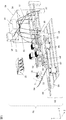
- FIG. 3 is a perspective view of a pretreatment integrated electrophoretic device.
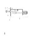
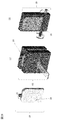
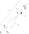
- Schematic diagram of a capillary array. Partially enlarged view of the capillary The figure which shows the connection of a high voltage power supply and a capillary.
- FIG. 3 is a diagram showing high voltage control according to the first embodiment.
- FIG. 3 is a top view of the pretreatment integrated electrophoretic device.
- the figure which shows an information processing system. 6 is a perspective view of a pretreatment-integrated electrophoretic device of Example 2.
- FIG. FIG. 6 is a diagram showing a pump unit of the second embodiment.
- FIG. 6 is a diagram showing a pump unit of Example 3;
- FIG. 6 is a diagram showing high voltage control according to the fourth embodiment.
- FIG. 8 is a diagram showing high voltage control of the fifth embodiment.
- FIG. 16 is a diagram showing high voltage control of the sixth embodiment.
- FIG. 10 is a diagram showing a capillary array of Example 7.
- FIG. 13 is a diagram showing an electrophoresis device of Example 12.
- the cartridge holding function, liquid feeding function, stirring function, heating/cooling function, polymer filling function and voltage application function of the electrophoresis process in the pretreatment process which has been performed simultaneously for multiple samples up to now, are performed for each sample.
- the problem could be solved if it could be operated independently, and the structure to realize it.
- they have found a structure in which at least the irradiation light source, the detector, and the constant temperature bath can be shared while operating independently.
- the existing device is generally equipped with a function of setting the temperature of the constant temperature bath for keeping the temperature of the capillary constant at about 45°C to 70°C.
- the constant temperature bath can be shared. Further, even when a plurality of applications are performed, it is not necessary to change the temperature of the constant temperature bath when the set temperatures of the constant temperature bath are the same, and different applications can be simultaneously performed by sharing the constant temperature bath.
- one irradiation light source irradiates irradiation light and penetrates a plurality of capillaries.
- irradiation is performed only during electrophoresis, and fluorescence is detected by the detector, but the conditions for penetration are that the irradiation parts of the capillaries are aligned accurately and that all capillaries are filled with polymer.
- the same voltage is simultaneously applied to all capillaries. When there is only one detector, the reading position at the detector is calibrated for the capillary No.
- the irradiation light penetrates inside the capillary and emits scattered light at the same time.
- the scattered light adversely affected the detection of at least adjacent capillaries.
- the irradiation light penetrates inside the capillary and emits scattered light at the same time.
- the scattered light adversely affected the detection of at least adjacent capillaries.
- the irradiation light penetrates inside the capillary and emits scattered light at the same time.
- the scattered light adversely affected the detection of at least adjacent capillaries.
- the capillaries are filled with polymer, even if there is no analysis sample in a certain capillary or even if no voltage is applied, it is detected by irradiating the capillary with excitation. There was only background noise generated by the device. Further, even if the polymer was filled with irradiation light and was detected, if the filling was possible without bubbles, the fluctuation of the background noise was minute. As a result of these studies, it was found that the irradiation light
- the irradiation method of the irradiation light to the capillaries the example of penetrating a plurality of capillaries was described above, but the method of dividing the light into the number of capillaries and irradiating each capillary, or the width of a plurality of aligned capillaries There are various methods of irradiating light, such as a method of spreading and irradiating irradiation light. If the capillaries not used for the analysis are filled with the polymer, the generation of scattered light can be prevented, and any irradiation method can be used.
- a capillary array in which a plurality of capillaries are bundled has been commercialized, and the same voltage is applied to the plurality of capillaries at the same time.
- one end of each capillary is passed through one hollow conductive pipe, and the other end of the plurality of capillaries is bundled with resin to form a capillary head.
- the end of the capillary through which the conductive pipe is passed is dipped in the buffer solution container on the cathode side, and the capillary head at the other end is dipped in the buffer solution container on the anode side.
- a metal plate is in contact with the conductive pipe.
- a high voltage is applied to the polymer inside the capillary through the cathode side buffer solution container.
- the metal plate is in contact with the conductive pipe that passes through multiple capillaries with the same configuration, and the cathode-side buffer solution container is also the same, so one high-voltage power supply can simultaneously apply the same voltage to all the capillaries. Is applied.
- the output of the high voltage power supply is first divided. Also, one cathode buffer solution container is prepared for each capillary. A polymer container and a supply mechanism, an example of dividing and an example of not dividing were found.
- the pretreatment-integrated electrophoretic device of the present invention will be described by taking STR analysis, which is one of the applications, as an example.
- STR analysis will be described as an example, but it is an example for explaining the present invention, and various fragment analyzes including STR analysis, MLPA analysis (Multiplex Ligation-dependent Probe Amplification), SNP analysis (Single Nucleotide Polymorphism), etc. , Can be used for sequence analysis.
- STR analysis is one of the applications, as an example.
- STR analysis will be described as an example, but it is an example for explaining the present invention, and various fragment analyzes including STR analysis, MLPA analysis (Multiplex Ligation-dependent Probe Amplification), SNP analysis (Single Nucleotide Polymorphism), etc. , Can be used for sequence analysis.
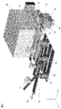
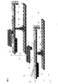
- FIG. 1 shows a perspective view of a pretreatment-integrated electrophoretic device 01 of this embodiment.
- the auto sampler 02 is an automatic carrying stage unit having driving directions of XY axes or XYZ axes.
- the autosampler 02 shown in FIG. 1 is driven by XY axes.
- a pretreatment unit 03, a cartridge cover 04, and a polymer delivery unit 05 are mounted on the auto sampler 02.
- the transported items are the cartridge 06, the cathode side buffer solution container 07, the waste liquid container 08, the anode side buffer solution container 09, and the polymer container 10, all of which are consumable items installed by the user.
- the autosampler 02 is configured to have an XY axis by arranging and configuring the cartridge 06, the cathode side buffer solution container 07, the waste liquid container 08, the anode side buffer solution container 09, and the polymer container 10 as shown in FIG. It is possible to drive.
- the auto sampler 02 of this embodiment is provided by the number of cartridges 06 that can be mounted.
- the cartridge 06 is installed by the user on the pretreatment unit 03 mounted on the auto sampler 02, and is fixed to the auto sampler 02 with high positional accuracy by closing the cartridge cover 04 manually or automatically.
- the polymer container 10 is set by the user on the polymer delivery unit 05 mounted on the auto sampler 02 and fixed manually or automatically with high positional accuracy.
- the cathode buffer solution container 07, the waste solution container 08, the anode buffer solution container 09, and the polymer container 10 are set by the user and fixed manually or automatically on the auto sampler 02 with high positional accuracy.
- the conductive pipe 35 of the capillary 31 or the capillary head 32 is accessed. Details of the capillary array 14 will be described later.
- the pretreatment-integrated electrophoretic device 01 shown in FIG. 1 has the same number of autosamplers 02 and capillaries 31, and the autosampler 02 is XY-axis driven. Although not shown, more autosamplers 02 than the number of capillaries 31 may be provided so that more cartridges 06 than the number of capillaries 31 can be installed. In this case, the auto sampler 02 is driven in the XYZ axes and the configuration is complicated, but it is possible to improve the processing efficiency.
- the pretreatment unit 03 is a unit mounted on the auto sampler 02 for performing liquid feeding and stirring operations.
- the cartridge 06 is installed by the user, and the cartridge cover 04 is closed manually or automatically.
- the pretreatment unit 03 acts on the cartridge 06, and feeds and agitates the reagent and sample solution inside the cartridge 06 by an external force.
- the liquid sending function is a good example, for example, in which a cartridge 06 has an elastomer thin film with a film thickness of about 0.1 mm to 1 mm attached and the liquid is sent by pulsating like a diaphragm pump with air pressure.
- various liquid delivery methods such as EWOD (Electrifying on Dielectric) and a method of pushing out liquid droplets by air pressure.
- the stirring operation required for mixing is performed by operations such as pipetting, Vortex, and tapping that are manually performed, and is simply an operation of mixing and moving liquid substances of different origins. Therefore, it is a good example to simply perform the stirring operation like a dropper using the liquid sending function, and in order to achieve higher stirring efficiency, even if the cartridge 06 is provided with a function to give high-speed vibration. good.
- the cartridge 06 is a device for pretreatment in which an input is a sample sample and an output is an analysis sample.
- the cartridge 06 is filled with the reagent necessary for the pretreatment process, and in the case of the open type, the reagent is externally charged into the cartridge 06.
- the first is a sample cartridge.
- the sample cartridge when the specimen sample is loaded, extracts the DNA with the Lysis Buffer.
- the extract is mixed with Primer Mix and Master Mix necessary for the PCR reaction, and the DNA is amplified through the PCR reaction.
- the amplified DNA is quantified, mixed with formamide and denatured into a single strand (also heat denatured if necessary), and electrophoresed as an analysis sample.
- the denaturation of the DNA into a single strand is preferably carried out by mixing the DNA with formamide and heat denaturation, but it is also possible to mix the DNA with formamide or heat denaturation.
- the second is the Negative Control cartridge.
- the PCR reaction is carried out without inserting the specimen sample, and the electrophoresis is carried out in the same procedure as the sample cartridge except for the above.
- the fact that nothing is detected is a cartridge that confirms that the PCR reaction system is not contaminated with extra nucleic acids (no contamination has occurred).
- the third is the Positive Control cartridge.
- a known control DNA is put in place of the specimen sample to carry out a PCR reaction, and otherwise the electrophoresis is carried out in the same procedure as the sample cartridge. It is a cartridge that confirms that the PCR reaction was performed correctly by measuring the control DNA.
- the fourth is the Ladder cartridge. Without performing a PCR reaction step, perform electrophoresis by mixing Allelic Ladder and formamide, which are internal indicators for analysis.
- cartridge 06 is a consumable item that is removed after use.
- the cartridge cover 04 has a function of opening and closing manually or automatically and fixing and holding the cartridge 06 when closed.
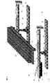
- the heating/cooling unit 11 is a structure including a radiator 13, a heat exchange element, and a heat conduction block 12. Although not shown, the heat exchange element is preferably arranged between the radiator 13 and the heat conduction block 12.
- the heating/cooling unit 11 is a temperature control unit for repeatedly heating and cooling a mixed solution of a DNA sample, a Primer Mix, and a Master Mix extracted from a specimen sample to perform a PCR reaction.
- the aforementioned mixed liquid is present in the cartridge 06. Furthermore, since it is important to repeat heating and cooling in the PCR reaction quickly and accurately, the heating/cooling unit 11 needs to contact the cartridge 06. Therefore, the cartridge cover 04 is open, and the heating/cooling unit 11 is fitted in the opening. As a result, the heating/cooling unit 11 and the cartridge 06 are configured to be in direct contact with each other. When the thermal conductivity of the cartridge cover 04 is high, the heating/cooling unit 11 may heat or cool the cartridge 06 through the cartridge cover 04.
- the heat exchange element be a component such as a Peltier element that can rapidly raise and decrease the temperature.
- the heat conduction block 12 is a component for mediating the amount of heat between the heat exchange element and the PCR section of the cartridge 06, and is provided to evenly transfer the heat to the cartridge 06. Therefore, it is desirable that the heat conduction block 12 has a high heat conductivity and a low heat capacity. Therefore, it is one of the preferable configurations to use a material such as aluminum that is hard and has high thermal conductivity, and to design the volume to be small.
- the radiator 13 is a part of the heating/cooling unit 11, and is a structure for cooling the heat exchange element with high efficiency. Therefore, it contacts one or both of the heat exchange element and the heat conduction block 12.
- the radiator 13 is generally called a radiation fin, and has a structure in which a metal material has a large heat transfer area to increase the amount of heat transferred.
- an air cooling fan is attached so that the radiator 13 is exposed to the wind.
- the waste liquid container 08 has a function of discharging excess polymer injected into the capillary 31 and old polymer used last time and temporarily stocking it.
- the waste liquid container should be filled with some liquid in order to improve drainage during waste liquid and to prevent crystallization due to drying. Is desirable.
- the liquid is preferably pure water, a buffer solution, a liquid similar to the buffer solution, or the like.
- the waste liquid container 08 and the cathode side buffer solution container 07 are different containers, but a configuration in which the waste liquid container 08 and the cathode side buffer solution container 07 are the same container is also one of the desirable modes.
- the polymer container 10 is a container containing a polymer.
- the polymer delivery unit 05 is a unit for sending the polymer in the polymer container 10 to the capillary 31.
- Polymer is a separation medium that gives a difference in migration speed to the analysis sample during electrophoresis.
- the separation medium has both fluidity and non-fluidity, a fluid polymer is used in this example.
- the polymer container 10 and the polymer delivery unit 05 of this embodiment will be described with reference to FIG. Although the polymer delivery unit 05 of FIG. 1 is arranged on the side surface of the polymer container 10, it may be arranged below the polymer container 10.
- the polymer container 10 shown in FIG. 2A includes a cylindrical tube 21 (which is called a syringe in a narrow sense), a seal part 22 that seals the polymer inside the tube and is movable inside the tube, and a polymer inside the tube. It has a connecting body 23 to which the capillaries are connected while being fastened. With the capillary 31 in contact with or through the connecting body 23 and in contact with the polymer liquid, an external force is applied from the bottom of the polymer container 20 to push up the sealing component to inject the polymer into the capillary 31. An external force mechanism that operates the bottom of the polymer container is the polymer delivery unit 05.
- the polymer delivery unit 05 of FIG. 2A includes a plunger 24. The polymer is injected into the inside of the capillary by pushing up the seal part 22 with the plunger 24.
- the advantage of the cylindrical polymer container 10 is that the polymer delivery unit 05 can be a simple structure with a uniaxial mechanism for moving the plunger 24 up and down, and the polymer delivery unit 05 can have a simple structure, and the dead volume in the polymer container 10 is small. Is.
- the pouch 25 and the connection body 26 have no pusher.
- the pouch is pushed from the outside so as to be sandwiched (see FIG. 2B(1)), or the polymer to be contained is squeezed from the bottom of the pouch (see FIG. 2B(2)), The polymer is injected into the capillary 31.
- the advantage of using the pouch-shaped polymer container 25 is that it can be provided to the user at low cost because the structure of the container itself is simple and it is easy to design inexpensively.
- the polymer container 10 is arranged in the auto sampler 02 so that the capillary head 32 can be inserted.
- the polymer may be injected into the capillary from the 35 side.
- the waste liquid container 08 is arranged on the side of the capillary head 32.
- the anode side buffer solution container 09 and the cathode side buffer solution container 07 are both containers containing a buffer solution containing an electrolyte. Both the cathode side buffer solution container 07 and the anode side buffer solution container 09 are mounted on the autosampler 02.
- anode electrodes made of a conductive material that is resistant to corrosion as platinum, SUS, etc. are mounted in the apparatus by the number of capillaries.
- the capillary 31 When a high voltage is applied to the capillary 31, the anode electrode is arranged so as to come into contact with the internal solution in the anode-side buffer solution container 09.
- the anode buffer solution When a high voltage is applied, the anode buffer solution is connected to the ground via the anode electrode.
- the high voltage generated from the high-voltage power supply unit 15 passes through the high-voltage wiring, the metal plate of the capillary, the conductive pipe, the cathode side buffer solution, the capillary element wire, the capillary head, the anode side buffer solution, and the anode electrode, and the ground voltage. It is applied by connecting to.
- the irradiation light 17 emerges from the light source of the irradiation unit 16 and reaches the irradiation detection area 33 of the capillary directly or through some optical components. When n capillaries C1, C2... Cn are installed, the irradiation light 17 successively passes through the capillaries 31 C1, C2... Cn in order.
- the information light emitted from the analysis sample by the irradiation light 17 is detected by the detector 18 either directly or through some optical components to obtain detection data.
- the irradiation light 17 is a laser light.
- the analysis sample is DNA to which a fluorescent dye is attached while being amplified by a PCR reaction.
- the information light is fluorescence excited by laser light, and the fluorescent color is light having a wavelength depending on the base.
- light with an extra wavelength for example, the wavelength of laser light
- the filter that is an optical component in the detection data
- the detector for each wavelength is separated by a spectrometer that is another optical component. It is split into 18 different positions. For example, when an image is picked up by the detector 18, the capillaries C1, C2... Cn are divided in the vertical direction, and the light of each wavelength is divided in the horizontal direction for detection.
- the detected data is captured by the controlling computer and analyzed appropriately by the software.
- the user can control the functions of the device with the control computer and can send and receive the data detected by the detector 18 in the device.
- the detection data can be obtained as an analysis result by software included in the control computer or software included in another analysis computer based on the data obtained from the control computer.
- an irradiation method will be described as an example in which the irradiation light is applied to the irradiation detection area 33 of the capillary 31 so as to sequentially pass through the capillary 31, but the irradiation light 17 is divided into the number of the capillaries 31. Then, there are various light irradiation methods such as a method of irradiating each capillary 31 and a method of irradiating the capillaries 31 by spreading the irradiation light 17 to the width of a plurality of aligned capillaries 31, and any irradiation method is available. Good.
- the constant temperature bath unit 19 has a function of keeping the temperature of the capillary array 14 at a set temperature. There is an effect that the filling speed is increased when the polymer is filled, and the movement speed difference of the analysis sample in the electrophoresis is kept constant during the electrophoresis.
- FIG. 1 the interior of the constant temperature bath unit 19 is shown so that it can be seen.
- the wiring route of the capillary array 14 can be three-dimensional instead of two-dimensional plane. Therefore, the constant temperature bath unit 19 has a heater such as a polyimide heater or a rubber heater in a constant temperature housing with high heat insulation.
- a contact type constant temperature bath may be used to shorten the temperature raising time.
- a heat insulating plate having high heat conductivity, heat transfer coefficient and heat quantity is bent along the wiring route of the capillary array 14, and a heater having a flat surface is attached to the bent heat insulating plate.
- a heat conductive elastomer member for wrapping the capillary wire and transmitting heat generated from the heater is attached onto the heater.
- a structure in which a heat insulating material is provided so as to sandwich the capillary with a heat insulating plate, a heater, and a thermally conductive elastomer bonded together can be considered. In the case of this configuration, the order of attaching each member is not limited to this.
- the detection unit is a unit in which the detector 18 and optical system components are combined. Although not shown, the fluorescence is detected by the detector 18 via a plurality of optical system components. Examples of the optical system component include an LP filter that cuts unnecessary irradiation light and a spectroscope that disperses the fluorescence wavelength. When detecting with the detector 18, each capillary 31 and the emitted wavelength are separated. Any method may be used as long as it can be detected.
- the detector 18 may be, for example, a CCD area image sensor or a CMOS camera.
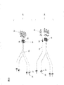
- FIG. 3A is an exploded view of the capillary array 14 shown in FIG. 1, and is an enlarged view of a part of FIG. 3B.
- the capillary 31 is composed of a glass tube having an inner diameter of several tens to several hundreds of microns and an outer diameter of several hundreds of microns, and its surface is coated with a polyimide coating to improve its strength.
- Each of the capillaries 31 is cut into the same length, and the ones connected to the polymer container 10 are individually bundled by a non-conductive substance. This is called a capillary head 32.
- the capillary wire 31 is exposed from the end point of the capillary head 32.
- the irradiation detection region 33 of the capillary irradiated with the irradiation light is a position where the irradiation light is irradiated inside the capillary, and at the same time, a position where the information light emitted from the analysis sample is detected. Therefore, the polyimide coating is removed so that the light energy emitted by the irradiation light can be efficiently received and that the information light generated from the analysis sample by the irradiation light can be easily detected. All the irradiation detection areas 33 are aligned and fixed with high precision, and are bundled by the detection holding component 34.
- the detection holding component 34 is a component that aligns and fixes the irradiation detection regions 33 with high accuracy. Further, since the irradiation unit 16 irradiates the irradiation detection area 33 with the irradiation light 17 and determines the position for detecting the information light, the outer shape or the positioning hole of the detection holding component 34 is a component manufactured with high accuracy. Similarly, the constant temperature bath is provided with a mechanism for fixing the detection holding component 34 with high positional accuracy.
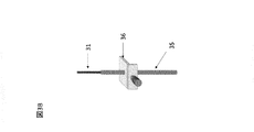
- each capillary strand 31 is passed through each conductive pipe 35 and fixed in an exposed state or slightly protruding by about 0.5 mm. Has been done.
- the capillary end on the conductive pipe side is shown in FIG. 3B.
- the individual conductive pipes 35 are fixed to different metal plates 36, respectively.
- the metal plate 36 and a part of the conductive pipe 35 are protected by a load header 37 made of a non-conductive material.
- the load header 37 that holds the metal plate 36 and the conductive pipe 35 together may be separate, the same part, or connectable parts.
- the high-voltage wiring that supplies the power from the high-voltage power supply unit 15 contacts the metal plate 36 in the load header 37, the voltage is applied to the conductive pipe 35, and it functions as a cathode voltage. ..
- each capillary 31 cannot be individually replaced, but it is possible to provide the user with the capillary array 14 that can be easily attached.
- the existing capillary array 14 aims to simultaneously electrophorese all the plurality of capillaries 31 at the same voltage, all the conductive pipes 35 are fixed to one metal plate 36 in a state of being aligned at regular intervals. And is protected by a single load header. Further, on the opposite side, all capillaries 31 are bundled into one point and enclosed in a single capillary head 32. With this configuration, the existing capillary array 31 can apply a single voltage and can only apply the voltages at the same time. [High-voltage wiring, high-voltage power supply] The high voltage power supply and high voltage wiring of the present invention will be described with reference to FIG.
- one high-voltage power supply has one high-voltage wiring, and a high voltage is applied to multiple capillaries via metal plates.
- the size of the required voltage differs depending on the step of the electrophoresis process, and it depends on the user's intended application and analysis sample concentration, so the output can be finely adjusted (output variable) so that the user can set it. ..
- the conductive pipes 35 of the capillaries are provided with the respective metal plates 36. It is a structure with. Therefore, a plurality of high voltage wirings 41 for applying the voltage of the high voltage power supply unit 15 to the capillaries 31 are also required.
- the high-voltage power supply unit 15 is configured to be able to individually apply a voltage to each capillary 31, and can apply a voltage according to each electrophoresis step.
- the high-voltage wiring 41 is preferably configured such that the tip on the side connected to the capillaries can be easily attached to and detached from the capillaries.
- a plug in which the tip of a cylinder of a conductive member is processed into a hemispherical shape is manufactured, the lead wire of the high-voltage wiring 41 is connected to the plug, and the plug is assembled so as to operate when pushed by a spring.
- the operation plug passes through the connection port provided in the load header 37 of each capillary 31 and comes into contact with the metal plate 36 to stop.
- the casing of the operating plug and the load header 37 are each made of an insulating material, and are configured so as not to discharge from a path other than the conductive wire, the plug, and the metal plate. For example, insert a highly insulating elastomer between the working plug and the load header. With such a configuration, a high voltage can be applied to each capillary 31 without detaching the working plug of the high-voltage wiring 41 and the load header 37 of each capillary 31 and discharging to the outside.
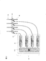
- FIG. 5 shows one example of controlling the high-voltage power supply unit 15 shown in FIG.
- Step 0 The user swabs to collect oral cells from the subject or biological cells such as a blood sample using a kit as a sample.
- Step 1 The user inserts the sample sample into the cartridge 06. Then, it is mixed with the Lysis Buffer inside the cartridge 06, and DNA is extracted from living cells.
- Step 2 The user installs the cartridge 06 in the pretreatment unit 03.
- Step 3 The pretreatment unit 03 sends a fixed amount of the DNA sample solution extracted by the Lysis Buffer in the cartridge 06. Furthermore, it mixes with Primer Mix and Master Mix which were enclosed in the cartridge 06.
- Step 4 The heating/cooling unit 11 heats and cools the cartridge 06, and the heating and cooling are repeated in the mixed solution of the extracted DNA sample and the Primer Mix and Master Mix in the cartridge.
- the heating/cooling temperature, time, and the number of cycles basically follow the protocol of the PCR reagent used.
- Step 5 After the PCR reaction, the solution is denatured into single strands and used as an analysis sample.
- the steps performed by hand are automated as they are, it is common to quantify the solution after PCR reaction, mix a part of it with formamide, and heat.
- a constant amount of the liquid amount after the PCR reaction is sent to another location inside the cartridge 06, stocked, and further mixed with formamide. If the dynamic range in the detection unit of the device is sufficiently large, it may be mixed with formamide without performing such quantification.
- Step 6 The device activates the autosampler 02, connecting the waste liquid container 08 to one side of the capillary and the other to the polymer container 10.
- the conductive pipe 35 side of the capillary is connected to the waste liquid container 08
- the capillary head 32 is connected to the polymer container 10.
- the capillary head is connected to the waste liquid container 08 and the conductive pipe 35 is connected to the polymer container 10.
- Step 7 The apparatus operates the auto sampler 02 to bring the conductive pipe 35 into contact with the cathode side buffer solution container 07 and bring the capillary head 32 into contact with the anode side buffer solution container 09.
- Step 8 The apparatus applies a voltage of about ⁇ 15 kV to ⁇ 20 kV to the capillary 31. This is intended to eject the polymer ions injected into the capillary 31 to improve the separation performance during measurement, and is called PreRun.
- a voltage is applied from the high voltage power supply unit 15 to the polymer inside the capillary through the high voltage wiring 41, the load header 37, the conductive pipe 35, and the cathode side buffer solution container 07.
- Step 9 The apparatus operates the autosampler 02, brings the conductive pipe 35 into contact with the analysis sample in the sample well of the cartridge 06, and brings the capillary head 32 into contact with the anode-side buffer solution container 09.
- Step 10 The apparatus applies a voltage of 0.5 kV to 2.0 kV to the capillary 31.
- the analysis sample is electrophoresed in the capillary 31 from the connection port of the cartridge 06.
- the constant temperature bath unit 19 needs to maintain the capillary 31 at a constant temperature and the temperature is stable.
- Step 11 As in step 7, the autosampler is operated to bring the conductive pipe 35 of the capillary into contact with the cathode side buffer solution container 07 and bring the other capillary head 32 into contact with the anode side buffer solution container 09.
- Step 12 The high voltage power supply unit 15 applies a voltage of 8.0 kV to 12.0 kV to the capillary 31.
- the analysis sample moves inside the capillary 31 filled with the polymer from the side of the conductive pipe 35 to the side of the capillary head 32.
- Step 13 The device irradiates the irradiation detection region 33 of the capillary 31 with the irradiation light 17 from the irradiation unit 16.
- Step 14 The analysis sample moved by electrophoresis sequentially reaches the irradiation detection region 33 of the capillary.
- the fluorescent dye labeled on the analysis sample emits light by the irradiation light 17.
- the fluorescent color labeled differs depending on the base of the analysis sample.
- Step 15 The detection unit detects the emitted fluorescence.
- the fluorescence is detected by the detector 18 via a plurality of optical system components of the device.
- the optical system component include an LP filter that cuts unnecessary irradiation light and a spectroscope that disperses the fluorescence wavelength.
- the anode electrode comes into contact with the internal solution of the anode side buffer solution container 09.
- the buffer solution on the anode side is connected to the ground via the anode electrode.
- the high voltage generated from the high voltage power supply unit 15 is applied to the high voltage wiring 41, the metal plate 36 provided on the capillary, the conductive pipe 35, the cathode side buffer solution, the capillary wire 31, the capillary head 32, the anode side buffer solution, and the anode. It is applied by connecting it to the ground through the electrode.
- step 15 are an example until the device obtains the detection data.
- step 0 is a sample sample acquisition process by the user
- steps 1 to 5 are pretreatment processes
- steps 6 to 15 are electrophoresis processes.
- step 0 there is a step of analyzing and displaying the detection data obtained in step 15 by software and a step of saving the data by the user, but it is unnecessary for explaining the present invention. , Not mentioned here.
- steps 1 to 15 are shown one by one. In fact, with the configuration of the present invention, some steps can be performed in parallel and a shorter TAT can be realized. For example, both the pretreatment process, steps 1 to 5, and the electrophoretic process, steps 6 to 8, must be completed by step 9. Therefore, step 6 does not necessarily have to follow step 5 and can proceed in parallel.
- FIG. 6 is a top view of the pretreatment-integrated electrophoretic device 1.
- the state of performing individual electrophoresis for each cartridge 06, which is the effect of the present invention, will be described with reference to FIG.
- the high-voltage power supply, high-voltage power supply wiring, the detection unit, and the constant temperature bath unit are omitted for the sake of clarity, but they are included in the device.
- the waste liquid container 08, the polymer container 10, the cathode side buffer solution container 07, the anode side buffer solution container 09, the cartridge 06 and the cartridge cover 04 are provided with a capillary 31.
- a connection port is provided for connection.
- the connection port provided in the waste liquid container is h1
- the connection port provided in the polymer container is h2
- the connection port provided in the cathode buffer solution container is h3
- the connection ports provided in the anode buffer solution are h4 and h6,
- the connection port provided on the cartridge and the cartridge cover is designated as h5.
- step 6 the conductive pipe 35 contacts the connection port h1 of the waste liquid container 08, and the capillary head 32 contacts the connection port h2 of the polymer container 10.
- the conductive pipe 35 contacts the connection port h3 of the cathode side buffer solution container 07, and the capillary head 32 contacts the connection port h4 of the anode side buffer solution container 09.
- the conductive pipe 35 contacts the connection port h5 of the cartridge 09 and the cartridge cover 04, and the capillary head 32 contacts the connection port h6 of the anode side buffer solution container 09.
- the distances h1 and h2, the distances h3 and h4, and the distances h5 and h6 are equal distances x1. .. Further, by arranging these connection ports h1, h2, h3, h4, h5, h6 in one row in the X-axis direction, for example, the drive shaft of the autosampler 02 that requires three axes of the XYZ axes in the existing device can be used. , XY axes can be used, and an inexpensive device can be provided to the user.
- the X-axis is the linear direction connecting the cathode side buffer solution container 07 and the sample well (or the sample tube described later) of the cartridge 06
- the Z-axis is horizontal to the installation plane of the device and orthogonal to the X-axis
- the remaining Y axis is orthogonal to the X and Z axes.
- all the auto samplers 02 are aligned in the Z-axis direction
- a plurality of capillaries 31 are aligned in the same direction and have an X-axis.
- the X-axis of each autosampler 02 also has each capillary 31. According to the X-axis direction in which the capillary head 32 and the conductive pipe 35 are connected.
- the uppermost capillary is C1 and the lowermost capillary is C4.
- a lane is an operation unit in which the autosampler 02, various component groups mounted on the autosampler 02, and the apparatus including the capillary 31 can be individually electrophoresed.
- the operation unit using the capillary C1 is Lane1
- the operation unit using the capillary C4 is Lane4.
- Lane 1 has finished steps 1 to 13 and is executing steps 14 and 15.
- the irradiation light 17 from the irradiation unit 16 is irradiated onto the irradiation detection region 33 of the capillary C1, and the information light is emitted from the analysis sample that has moved in the polymer by electrophoresis, and is detected by the detector 18.
- a voltage of 10 kV is applied for electrophoresis.
- Lane2 is the lane executed next to lane1. Steps 1 to 9 are completed and step 10 is being executed.
- the conductive pipe 35 of the capillary is connected to the connection port h5 of the cartridge 06, and the analysis sample is being injected into the capillary C2. Since the Lane 1 is being executed, the irradiation light 17 naturally passes through the capillary C1 and reaches the capillary C2, and the detection unit is also executing the imaging of C2. However, since Step 14 and subsequent steps have not been reached, the obtained detection data continues to be discarded until Lane 2 reaches Step 14.
- the voltage is 1.5 kV due to sample injection.
- Lane3 is the lane executed next to lane2. Steps 1 to 3 are completed, and step 6 is being executed while repeating the PCR reaction of step 4.
- the irradiation light 17 penetrates the capillaries C1 and C2 to reach the capillary C3 as in the case of Lane2, but the detection data obtained similarly to the case of Lane2 continues to be discarded until step 14.
- the voltage is 0 kV.
- Lane4 is the lane executed next to lane3.
- the user is about to insert the cartridge 06.
- the irradiation light 17 penetrates through the capillaries C1, C2, and C3 to reach the capillary C4 as in the case of Lane2 and Lane3.
- the scattered light to the extent that it becomes measurement noise is not generated because the polymer used last time remains inside the capillary C4.
- the detection data obtained similarly to Lane 2 and Lane 3 are continuously discarded until step 14.
- the voltage is 0 kV.
- the polymer used last time remained, but when the device is used for the first time or when the capillary is replaced, the polymer is loaded in all the capillaries even when the analysis sample is electrophoresed with one capillary. Fill to suppress the generation of scattered light.
- FIG. 7 is a diagram showing an informational connection in the first embodiment.
- a thin solid line indicates exchange of control information, detected data, power supply, and the like.
- the dotted line shows the electrical exchange from the high voltage power supply.
- Thick arrows indicate the flow of optical information.
- the control information includes a general bidirectional electric signal that specifies an operation for each unit, a measured value from each unit, execution completion, and the like.
- control information is directly exchanged with the main board from the main board for simplification, but when it is more beneficial than connecting one board between the main board and the component due to device configuration, It also includes sandwiching the relay board.
- an internal computer directly connected to the main board and mounted in the device, or an external computer for controlling the device from outside the device is required. ..
- the Software Control described in FIG. 7 includes this computer.
- FIG. 8 is a configuration diagram of a pretreatment-integrated electrophoretic device 01 having a different form from that of the first embodiment.
- the configurations of the auto sampler 02, the cartridge 06, the cartridge cover 04, the heating/cooling unit 11, the waste liquid container 08, and the cathode side buffer liquid container 07 are the same as those in the first embodiment.
- a pretreatment unit, a high-voltage power supply, a high-voltage wiring, an anode electrode, a control computer, a main board, and the like are also present as components.
- the pump unit 51 includes a polymer flow path block, a liquid feeding mechanism, an anode side valve, a liquid feeding mechanism side valve, and a check valve.
- the capillary array 14 is connected to the pump unit 51, and the polymer container 10 and the anode side buffer solution container 09 are connected to the pump unit 51.
- each capillary 31 is provided with a polymer delivery unit which is a drive source, whereas in the present configuration, the polymer can be injected by the pump unit 51 which is one drive source.
- the second is analytical performance. Since the capillary heads 32 do not have to be divided into the auto samplers 02 of each Lane and are connected together in the pump unit 51, the distance from the irradiation detection area 33 of the capillary array 14 to the capillary heads 32 is set as shown in the figure. Unlike Example 1, it can be shortened. When the capillaries 31 have the same length, the sample separation performance, which is one of the analytical performances, is better as the length from the tip on the introduction pipe 35 side to the irradiation detection region 33 is longer. Also, in accordance with this change, the positions of the irradiation light 17, the constant temperature bath unit 19, and the detector 18 are changed as shown in the figure.
- FIG. 9 is an example showing a specific configuration of the pump unit 51 shown in FIG.
- the polymer flow path block 52 made of an insulating material has n independent flow paths 53.
- One anode side buffer solution container 09 is connected to the n independent flow paths.
- the anode side buffer solution container 09 is connected to one anode electrode 54 provided in the polymer flow path block 52.
- the anode electrode 54 is connected to the device ground through the inside of the polymer flow path block 52. Even if the anode electrode 54 is not connected to the polymer flow path block, the anode electrode 54 is located somewhere in the device, one of which is connected to the ground and the other of which is n buffer solutions on the anode side. Any configuration may be used as long as it is individually connected to the container.
- the anode side buffer solution container 09 is removable from the polymer flow path block 52 and can be replaced by the user.
- n channels 53 are connected to the anode side buffer solution container 09.
- An anode valve 55 is provided in each flow path at this connection end point, and the opening/closing timing can be controlled by software.
- the capillary head 32 is connected to the other side of the flow path 53. Since the polymer is individually injected from the flow channel 53 into the capillary array 14 through the capillary head 32, this connection needs to be sealed and pressure-resistant.
- a preferable example is a screw structure of the capillary head 32, a method of connecting the polymer flow path block 52 by providing a tap, a lid structure of pressing the capillary head 32 after connecting the polymer flow path block 52, and the like.
- Another flow path is provided between the end points of each flow path, and the flow path 53 in the polymer flow path block is a three-way path.
- the other flow path is independently provided and connected to the liquid feeding mechanism 56, and the liquid feeding mechanism 56 is connected to the polymer container 10. Since the pipe diameter of the capillary wire 31 is extremely narrower than the pipe diameter of the flow path, if the anode side valve 55 is opened and the polymer is sent out from the liquid sending mechanism 56, the polymer is transferred to the anode side buffer solution container 09 due to the pressure difference. Flows. When the anode side valve 55 is closed and the polymer is sent out from the liquid sending mechanism 56, the polymer slowly flows into the capillary wire 31 due to the high pressure, but finally flows into the cathode side buffer solution container 07. ..
- liquid feeding mechanism 56 specifically, a high-pressure pump that drives the plunger is suitable.
- a high-pressure pump that drives the plunger is suitable.
- a container in which a plunger is combined in a syringe shape and a driving structure using a ball screw for driving the plunger Similar ones are widely known, and any liquid feeding mechanism 56 having a pressure capable of steadily injecting a high-viscosity separation medium into the inner diameter of the capillary 31 and a hermetically sealed liquid-feeding mechanism 56 may be used. Absent.
- each flow path 53 connected to the liquid supply mechanism 56 is provided with a liquid supply mechanism side valve 57, and then combined into one confluent flow path. It is desirable that the confluence channel is connected to the liquid sending mechanism 56, and the liquid sending mechanism 56 is connected to the polymer container 10.
- a method of arranging n liquid feeding mechanisms 56 for n capillaries is simple.
- FIG. 9 reproduces the state of the device shown in FIG. Further, this is an apparatus state similar to that of FIG. 6 in the first embodiment. That is, the total number of the capillaries 31 is four, the voltage of 10 kV is applied to the Lane1 corresponding to the capillaries C1, the 1.5 kV is applied to the Lane2 corresponding to the capillaries C2, and the capillaries C3 correspond to the capillaries C3. Lane3 is injecting a polymer, and Lane4 corresponding to the capillary C4 is in the process of replacing the cartridge.
- the high voltage generated from the high voltage power source 42 causes the high voltage wiring 41, the metal plate 36 of the capillary, the conductive pipe 35, It is applied by being connected to the ground through the cathode side buffer solution 07, the capillary strand 31, the capillary head 32, the flow path inside 53 of the polymer flow path block, the anode side buffer solution 09, and the anode electrode 54.
- the difference from the first embodiment is that each flow path 53 of the polymer flow path block enters between the capillary head 32 and the anode side buffer solution 09.
- Polymer is being injected in the capillary C3 of Lane3. Polymer injection is done in two steps. As a pre-process, the valve 55 on the anode side is opened, the valve 57 on the liquid feeding mechanism side is opened, and the pump of the liquid feeding mechanism 56 is driven. Then, the polymer is discharged into the anode side buffer solution container 09, and the flow path between the polymer container 10 and the anode side buffer solution container 09 is filled with the polymer. As a post-process, the anode side valve 55 is closed and the liquid feeding mechanism 56 is driven, so that the polymer is injected into the capillary C3. FIG. 9 shows a post process.
- the check valve 58 is provided to prevent the polymer from flowing back from the liquid sending mechanism 56 side to the polymer container 10 when the liquid sending mechanism 56 sucks and discharges, and the check valve 58 is provided in the liquid sending mechanism 56. It is not necessary when the function of is added.
- all n capillaries 31 are connected to the inside of one anode-side buffer solution container 09 via the channel 53 of the polymer channel block of the pump unit 51. Therefore, when a high voltage is applied to a certain capillary 31, the current flows from the anode side buffer solution 09 to the anode electrode 54 via the above-mentioned path and drops to the ground. At this time, most of the current flows to the ground having a zero potential, but theoretically, when the current flows backward to the other capillaries 31 because there is a flow path inside the anode buffer solution 09 that is connected to the other capillaries. I can think.
- FIG. 10 is a schematic diagram for calculating a backflow current, where I 1 is a current flowing in Lane 1 , I 2 is a current flowing in Lane 2 , and I 3 is a current flowing backward in Lane 3 .
- the voltage applied to Lane1 is 10 kV
- the voltage applied to Lane2 is 1.5 kV
- the voltages applied to Lane3 and Lane4 are 0 kV.
- the resistance up to the anode buffer solution 09, the anode electrode 54, and the ground is defined as the wiring resistance r
- the voltage applied to the wiring resistance r is defined as v.
- the resistance of the capillary and the flow path of Lane 3 is R 3 .
- the effect on electrophoresis is extremely slight. If you still want to prevent reverse current, you should not use the high-voltage power supply unit 15 that has a high-current power supply unit 15 that applies a high voltage to the capillary 31 and a backflow prevention circuit that combines electronic components such as diodes and capacitors. This is one of the preferred embodiments.
- a factor that increases the influence of the reverse flow of current on electrophoresis is that the electrical resistance of the capillary 31 becomes small.
- the polymer diameter of the capillary 31 is large, the length of the capillary 31 is short, the number of capillaries 31 is large, and the polymer has low electric resistance. And the like.
- FIG. 8 shows a specific configuration of the pump unit shown in FIG. 8 for preventing the extremely weak current reverse flow obtained in FIG. 10 in FIG.
- the polymer flow path block 52 made of an insulating material has n independent flow paths 53, but the difference from FIG. 9 is that n independent flow paths 53 are provided.
- the n anode side buffer solution containers 09 are individually connected to the flow path 53.
- the n anode side buffer solution containers 09 are individually connected to the n anode electrodes 54 provided in the polymer flow path block 52.
- the anode side buffer solution container 09 is removable from the polymer flow path block 52 and can be replaced by the user.
- a plurality of anode side buffer solution containers 09 are collectively stored in one holder 59.
- the number of the chambers may be one, and the number of chambers in the container may be divided into n, each of which is filled with the anode-side buffer solution.
- the n channels are individually connected to the anode side buffer solution container 09.
- An anode valve 55 is provided in each flow path at this connection end point, and the opening/closing timing can be controlled by software.
- FIG. 12 shows another embodiment of the high voltage power supply unit 15 for controlling the high voltage shown in FIG.
- one high voltage power supply 43 is provided with variable output high voltage ports 44 for the number of capillaries.
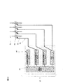
- FIG. 13 shows another embodiment of the high voltage power supply unit 15 for controlling the high voltage shown in FIG.
- This configuration is a configuration in which a fixed high-voltage power supply 45 with a fixed output is prepared.
- the application is fixed and the sample concentration is narrowed down to some extent.
- the voltage required in step 8, step 10, and step 12 of applying a voltage of the electrophoretic process described in Example 1 is determined.
- three types of high voltage required three types of fixed high voltage power supplies 45 are prepared, and four high voltage wirings 41 including GND of 0 kV are prepared for each capillary. It is a method of applying a high voltage mechanically or controlled according to the step of applying a voltage.
- This configuration has the advantage that the output of the high-voltage power supply is not variable but is fixed for each individual unit, so the development of the high-voltage power supply is easy and inexpensive.
- FIG. 14 shows another embodiment for controlling the high voltage power supply shown in FIG.
- This configuration is a configuration in which a plurality of high voltage ports 46 with fixed outputs are prepared for one high voltage power source 43.
- the high-voltage wiring 41 is prepared only for the number of capillaries, and the high-voltage power supply unit 15 mechanically connects the high-voltage port 46 with fixed output and the high-voltage wiring 41 in accordance with the step of applying each voltage.
- it is a method of controlling and applying a high voltage.
- This configuration also has the advantage that the output of the high-voltage power supply is fixed for each single unit, so the development of the high-voltage power supply is easy and inexpensive.
- FIG. 15 shows another example of the capillary array 14 shown in FIG. 3A.
- An alignment component 38 manufactured with high accuracy is fixed to the irradiation detection region 33 of each capillary 31. All the alignment parts 38 are aligned together and fixed by the alignment part holding part 39.
- the apparatus has a mechanism for fixing the alignment part holding component 39 with high positional accuracy.
- the irradiation unit 16 can irradiate the irradiation detection area 33 of the capillary with the irradiation light 17 and determine the position where the information light is detected.
- the advantage of this embodiment is that the aligning part holding component 39 of the capillary array 14 can be opened and the capillaries 31 can be replaced in units of one.
- the capillary arrays 14 capable of individually performing electrophoresis one by one can be biased in the number of times of use among a plurality of capillaries unless limited by software.
- the configuration is such that a maximum of n capillaries 31 can be installed, and the capillary numbers are C1, C2... Cn.
- the upper limit of the number of times the capillary 31 can be used is 500 times of electrophoresis.
- the capillaries C2... Cn are used about 100 times, only the number of uses of the capillaries C1 reaches 500 times, and the upper limit number of uses is reached. Conceivable.
- the configuration of the first embodiment not only the capillary C1 but also the capillaries C2... Cn must be replaced at the same time.
- the user or the device maintainer can replace only the capillary C1 and continue to use the capillaries C2... Cn.
- the role of the alignment part holding component 38 is to align and fix the capillaries 31, so that mounting the alignment part holding component 38 directly on the apparatus is also one of desirable configuration examples.
- FIG. 16 shows another embodiment of the heating/cooling unit 11 shown in FIGS. 1, 6 and 8.
- one heating/cooling unit 11 does not raise or lower the temperature, but a plurality of heating/cooling units 61 and 62 having different set temperatures are prepared, and the liquid in the cartridge moves to reduce the temperature.
- This is a configuration for performing cycle processing.
- the temperature required for the temperature cycle treatment by PCR is 3°C such as 4°C, 55°C, and 60°C
- a combination of the heating/cooling unit 61 of 4° C. and the heating/cooling unit 62 that also serves as 55° C. and 60° C. may be used.
- the heating/cooling units 61 and 62 are fixed to the cartridge cover 06 as shown in FIG.
- FIG. 17 shows another embodiment of the heating/cooling unit 11 shown in FIGS. 1, 6 and 8.
- a plurality of heating/cooling units 61/62 having different set temperatures are arranged in the X-axis direction, but the heating/cooling units 61/62 of the present embodiment are the device cover and the constant temperature bath unit. It is fixed to the cartridge cover 04 (not shown) and is not fixed to the cartridge cover 04.
- the liquid does not move in the cartridge 06 as in the eighth embodiment, but the auto sampler 02 drives the XY axes to move the cartridge 06 to the heat conduction block 12 of the heating/cooling unit 61/62. It is a structure to press against.
- a gap is provided in the cartridge cover 04 (not shown) so that the heat conduction block 12 of the heating/cooling units 61/62 is in contact with the cartridge 06.
- a configuration fixed to a unit or the like is preferable. It is desirable that at least a part of the cartridge cover 04 is made of a material having a high thermal conductivity and a high thermal conductivity so that the temperature of the cartridge 06 can be controlled through the cartridge cover 04.
- FIG. 18 shows another embodiment of the heating/cooling unit 11 shown in FIGS. 1, 6 and 8.
- the heating/cooling unit 63 of the present embodiment the combination of the heat exchange elements or heaters having different set temperatures and the heat conduction block 12 is arranged in the X-axis direction. It is fixed to the tank unit and not fixed to the cartridge cover 04. The same applies to the case where the autosampler 02 drives the XY axes to press the cartridge 06 against the heat conduction block 12 of the heating/cooling unit 11 when performing the temperature cycle process.
- the heating/cooling unit 63 of this embodiment has a configuration in which a plurality of heat exchange elements and heaters having different set temperatures and a plurality of heat conduction blocks 12 share one radiator 13.
- the advantage of this configuration is that the number of heat radiators 13 can be simply reduced, and that the height of a plurality of heat conduction blocks 12 can be easily adjusted. Since the radiator 13 is generally made of metal, it has a certain rigidity. Since a plurality of traditional heating blocks 12 and heat exchange elements and heaters are assembled using this structure as a common body, the user can be provided with an apparatus that is easy to adjust and has little individual difference as long as the entire horizontal is adjusted. be able to.
- FIG. 19 shows another embodiment of the heating/cooling unit and the radiator of FIGS. 1, 6 and 8.
- the heating/cooling unit 64 of this configuration is configured such that a plurality of heat conduction blocks 12 corresponding to a plurality of Lanes and having different set temperatures share one radiator 13.
- the cartridges 06 on the plurality of auto samplers are brought into contact with the integrated heating/cooling unit 64, which has a plurality of heat conduction blocks 12 having different set temperatures, which are connected to one radiator 13. Perform the key.
- the heating/cooling unit 64 is fixed to the device cover, the constant temperature bath unit, or the like, and does not move when the auto sampler 02 is driven. The advantage of this configuration is almost the same as that of the tenth embodiment.
- both the heat conduction block 12 for heating and the heat conduction block 12 for cooling share the single radiator 64, but when priority is given to stability and the temperature rising high temperature until reaching stability. It is also a good example to divide the radiator 64 according to the temperature.
- FIG. 20 is a configuration diagram of an electrophoretic device.
- the present invention is also applicable to an electrophoretic device for performing electrophoresis of the pretreated analysis sample as a general-purpose machine. Applicable.
- FIG. 20 shows a configuration example as a general-purpose electrophoresis device 70.
- the user determines the type and quantity of the analysis sample to be measured and injects it into the sample tube 71 having eight wells.
- the sample tube 71 has a sample septa 72 fitted therein by a user.
- the sample tube 71 and the sample septa 72 are housed in the sample holder 73.
- the sample septa 72 is an inner lid provided with a hole or slit through which the conductive pipe 35 passes, in an elastomer material designed to fit in the sample tube 71. Evaporation due to the passage of time after the sample tube 71 is installed in the apparatus is prevented, and carryover due to droplets adhering to the side surface of the conductive pipe 35 of the capillary is reduced.
- the sample holder 73 is a stocker that stores the sample tube 71 in a highly accurate position and stands upright, and is provided with a lid so that the sample tube 71 and the sample septa 72 do not fall off during analysis.
- the lid is provided with a hole or slit so that the capillary 31 can access the sample tube 71.
- the sample holder 73 is installed on the auto sampler with high positional accuracy and can be easily attached and removed by the user.
- the configuration shown in FIG. 20 is the same as that of the second embodiment. That is, the waste liquid container 08 and the cathode side buffer solution container 07 are installed in the auto sampler 02.
- the apparatus is provided with a capillary array 14, a constant temperature bath unit 19, a detector 18, a pump unit 51, an anode side buffer solution container 09, and a polymer container 10.
- a high voltage power source, high voltage wiring, and an irradiation unit having a light source for emitting irradiation light are installed.
- the main board which is an electric board and the control computer.
- a sample tube 72 is shown in FIG. 20 as a sample container in the apparatus, but for example, a 96-well well plate or the like is often used.
- the autosampler stage is configured so that the XYZ axes are operated instead of the XY two axes.
- the device configuration using the pump unit 51 similar to that of the second embodiment is used, but it is also a good example to configure the device configuration using the polymer delivery unit 05 as in the first embodiment.
- the present invention is not limited to a dedicated machine for a single application such as STR analysis, but a base sequence analysis apparatus as a general-purpose machine can be used to provide a user with an apparatus for performing individual electrophoresis. Can be provided.
- 01 Electrophoresis device integrated with pretreatment
- 02 Autosampler
- 03 Pretreatment unit
- 04 Cartridge cover
- 05 Polymer delivery unit
- 06 Cartridge
- 07 Cathode side buffer container
- 08 Waste container
- 09 Anode-side buffer solution container
- 10 Polymer container
- 11 Heating/cooling unit
- 12 Heat conduction block
- 13 Radiator
- 14 Capillary array
- 15 High voltage power supply unit
- 16 Irradiation unit
- 17 Irradiation light
- 18 Detector
- 19 Constant temperature bath unit
- 21 Tube
- 22 Seal part
- 23 Connection body
- 24 Plunger
- 25 Pouch
- 26 Connection body
- 32 Capillary head
- 33 Irradiation detection area
- 34 detection holding component
- 35 conductive pipe
- 36 metal plate
- 37 load header
- 38 alignment component
- 39 alignment portion holding component
- 41 high voltage wiring
- 42 high voltage power supply
- 43 High voltage power supply
- 44 Output
Landscapes
- Health & Medical Sciences (AREA)
- Life Sciences & Earth Sciences (AREA)
- Molecular Biology (AREA)
- Chemical & Material Sciences (AREA)
- Chemical Kinetics & Catalysis (AREA)
- Electrochemistry (AREA)
- Physics & Mathematics (AREA)
- Analytical Chemistry (AREA)
- Biochemistry (AREA)
- General Health & Medical Sciences (AREA)
- General Physics & Mathematics (AREA)
- Immunology (AREA)
- Pathology (AREA)
- Apparatus Associated With Microorganisms And Enzymes (AREA)
- Automatic Analysis And Handling Materials Therefor (AREA)
Abstract
Description
特許文献2:特許第6216451号
特許文献3:特許第6202713号
特許文献4:特許第6012518号
特許文献5:特許第6029366号
(1)カートリッジを任意のタイミングで設置できること
(2)カートリッジを設置した順に前処理プロセスが実行できること
(3)前処理プロセスが終わった順に電気泳動プロセスに移行できること
(1)カートリッジを任意のタイミングで設置できること
(2)カートリッジを設置した順に前処理プロセスが実行できること
(3)前処理プロセスが終わった順に電気泳動プロセスに移行できること
<電気泳動プロセスにおける恒温機能の共有>
既存の装置はキャピラリの温度を一定に保つ恒温槽の温度が、45℃~70℃程度まで設定できる機能が搭載されていることが一般的である。しかしながら、核酸分析のアプリケーションが固定であるとき、温度を変化させる必要がない点に着目し、キャピラリ交換などで装置を停止する以外は、恒温槽は一定温度でキャピラリの温度を維持していれば良いことを見出した。よって、恒温槽は共有することができる。また、複数のアプリケーションを行う際にも、恒温槽の設定温度が等しい場合には恒温槽の温度を変化させる必要がなく、異なるアプリケーションを、恒温槽を共有して同時に行うことが可能である。
<電気泳動プロセスにおける照射光源と検出器の共有>
既存の装置を例にすると、ひとつの照射光源が照射光を照射し、キャピラリ複数本の照射部を貫通する。既存の装置では電気泳動中にのみ照射し、検出器によって蛍光を検出しているが、貫通する条件はキャピラリの照射部が精度良く整列していることと、全てのキャピラリ内部にポリマーが充填していることである。既存の方法では全てのキャピラリに、同時に同電圧が印加される。検出器がひとつである場合、キャピラリNoに対して検出器での読み取り位置をキャリブレーションしている。
<キャピラリ1本ずつの電圧印加>
既存の装置では複数本のキャピラリが束ねられたキャピラリアレイが製品化されており、複数本のキャピラリには同時に同電圧が印加されている。キャピラリアレイの構造としては、中空の一本の導電パイプに一本ずつキャピラリの一端が通されており、複数本のキャピラリのもう一端を樹脂で束ねてキャピラリヘッドとしている。導電パイプが通されたキャピラリ端をカソード側緩衝液容器に浸し、もう一端のキャピラリヘッドをアノード側緩衝液容器に浸す。導電パイプには金属板が接している。この金属板に高電圧を印加することで、カソード側緩衝液容器を通してキャピラリ内部のポリマーに高電圧を印加する。金属板には、同様の構成で複数本のキャピラリを通した導電パイプが接しており、またカソード側緩衝液容器も同一であるため、ひとつの高電圧電源によって複数本のキャピラリ全てに同時に同電圧が印加される。
[オートサンプラー]
オートサンプラー02はXY軸またはXYZ軸の駆動方向を持つ自動搬送ステージユニットである。図1に示すオートサンプラー02はXY軸駆動である。オートサンプラー02には前処理ユニット03、カートリッジカバー04、ポリマーデリバリーユニット05が搭載されている。また、搬送物はカートリッジ06、カソード側緩衝液容器07、廃液容器08、アノード側緩衝液容器09、ポリマー容器10であり、これらは全てユーザーによって設置される消耗品である。詳細は後述するが、カートリッジ06、カソード側緩衝液容器07、廃液容器08、アノード側緩衝液容器09、ポリマー容器10を図1のような配置及び構成とすることで、オートサンプラー02はXY軸駆動にすることが可能にしている。
[前処理ユニット]
前処理ユニット03はオートサンプラー02に搭載された送液および撹拌動作を行うためのユニットである。
[カートリッジ]
ユーザーが取得した検体サンプルを装置が解析可能な解析サンプルに変性させるプロセスを一般的に前処理という。カートリッジ06はインプットが検体サンプルであり、アウトプットを解析サンプルとする前処理のためのデバイスである。密閉式の場合は、カートリッジ06には前処理プロセスに必要な試薬が封入されており、開放式の場合は外部からカートリッジ06に試薬を投入する。但し、いずれの場合にも検体サンプルを投入する必要がある。
[カートリッジカバー]
カートリッジカバー04は、手動または自動により開閉し、閉まった際にはカートリッジ06を固定し保持する機能を持つ。
[加熱冷却ユニット]
加熱冷却ユニット11は、放熱体13、熱交換素子、熱伝導ブロック12で構成された構造体である。熱交換素子は、図示されていないが、放熱体13と熱伝導ブロック12の間に配置するのが好適である。加熱冷却ユニット11は、検体サンプルから抽出されたDNAサンプル、Primer Mix、Master Mixの混合液に、加熱冷却を繰り返してPCR反応を行うための温調ユニットである。前述の混合液はカートリッジ06内に存在する。さらに、PCR反応における加熱と冷却は素早く正確に繰り返し行うことが重要であるため、加熱冷却ユニット11はカートリッジ06に接する必要がある。そのため、カートリッジカバー04は開口しており、開口部に加熱冷却ユニット11が嵌め込まれている。これにより、加熱冷却ユニット11とカートリッジ06は直接接するよう構成されている。また、カートリッジカバー04の熱伝導率が高い場合には、カートリッジカバー04越しに、加熱冷却ユニット11によりカートリッジ06を加熱または冷却を行ってもよい。
[放熱体]
放熱体13は加熱冷却ユニット11の一部であって、熱交換素子の冷却時に高効率に冷却を行う為の構造体である。よって、熱交換素子および熱伝導ブロック12の片方または両方に接する。
[廃液容器]
廃液容器08キャピラリ31に余分に注入したポリマーや、前回使用時の古いポリマーなどが排出され、一時的にストックする機能を持つ。ポリマーは一般的に高粘度で乾燥時に結晶化する高分子液体であるため、廃液時の液切れを良好にし、また乾燥による結晶化を防止するため、廃液容器は何らかの液体で満たされている方が望ましい。液体は、例えば純水や、緩衝液、緩衝液と類似の液体等が好適である。また、図1では、廃液容器08とカソード側緩衝液容器07は別の容器であるが、廃液容器08とカソード側緩衝液容器07が同一容器である構成も望ましい形態のひとつである。
[ポリマー容器、ポリマーデリバリーユニット]
ポリマー容器10は、ポリマーを内包した容器である。ポリマーデリバリーユニット05は、ポリマー容器内10のポリマーをキャピラリ31に送液するためのユニットである。
[カソード側緩衝液容器、アノード側緩衝液容器、アノード電極]
アノード側緩衝液容器09及びカソード側緩衝液容器07は、共に電解質を含む緩衝液を内包した容器である。カソード側緩衝液容器07とアノード側緩衝液容器09は、共にオートサンプラー02上に搭載されている。
[照射ユニット]
照射光17は照射ユニット16の光源から出て、直接またはいくつかの光学部品を経てキャピラリの照射検出領域33に到達する。n本のキャピラリC1、C2…Cnが設置されているとき、照射光17はC1、C2…Cnのキャピラリ31を順に連続して透過する。この照射光17により解析サンプルから発せられた情報光を直接、またはいくつかの光学部品を経て検出器18が検出することで、検出データとする。
[恒温槽ユニット]
恒温槽ユニット19は、キャピラリアレイ14の温度を設定した温度に保つ機能を有している。ポリマー充填時には充填速度を速め、電気泳動時には電気泳動における解析サンプルの移動速度差を一定に保つ効果がある。図1では、恒温槽ユニット19の内部が分かるよう記載している。本発明においては図1に示す通りキャピラリアレイ14の配線ルートが2次元の平面ではなく3次元となり得るため、恒温槽ユニット19は、ポリイミドヒータやラバーヒータなどのヒータが断熱性の高い恒温筐体内でキャピラリ素線31の大部分を保温する、空間恒温槽が望ましい。恒温筐体内の温度を均一に保つために、恒温筐体内に風を循環させるにファンを取り付ける構成も好ましい一例である。
[検出ユニット]
検出ユニットは、検出器18と光学系部品を組み合わせたユニットである。図示していないが、蛍光は複数の光学系部品を経て検出器18に検出される。光学系部品には、例えば不要な照射光をカットするLPフィルタ、蛍光波長を分光する分光器などが挙げられるが、検出器18で検出される際に、各々のキャピラリ31および発光した波長が分けて検出可能であれば、どのような方法でも構わない。検出器18は、例えばCCDエリアイメージセンサやCMOSカメラなどが考えられる。
[キャピラリアレイの構成]
本発明におけるキャピラリアレイ14の構成について、図3を用いて説明する。図3Aは、図1に示したキャピラリアレイ14の分解図であり、図3B一部の拡大図である。
[高電圧配線、高電圧電源]
本発明の高電圧電源と高電圧配線については、図4を用いて説明する。
<STR解析を目的とした装置におけるデータ取得工程の一例>
STR解析例に、核酸分析を行う前処理プロセスと電気泳動プロセスを一体化した本実施例の前処理一体型電気泳動装置における、ユーザーが検体サンプルを得てから装置がデータを得るまでの工程を単純化した一例を以下に示す。
ステップ0:ユーザーが、被験者からスワブで口腔内細胞、またはキットにより血液サンプルなどの生体細胞を検体サンプルとして採取する。
ステップ1:ユーザーが、検体サンプルをカートリッジ06に投入する。すると、カートリッジ06内部のLysis Bufferと混合され、生体細胞からDNAが抽出される。
ステップ2:ユーザーが、カートリッジ06を前処理ユニット03に設置する。
ステップ3:前処理ユニット03が、カートリッジ06内で、Lysis Bufferにより抽出されたDNAサンプル溶液を一定量送液する。さらに、カートリッジ06に封入されていたPrimer MixおよびMaster Mixと混合する。
ステップ4:加熱冷却ユニット11によりカートリッジ06の加熱及び冷却を行い、カートリッジ内で、抽出されたDNAサンプルとPrimer MixおよびMaster Mixの混合液に、加熱冷却を繰り返す。加熱冷却の温度、時間、サイクル数は、基本的に使用するPCR試薬のプロトコルに従う。
ステップ5:PCR反応後液を一本鎖に変性させて解析サンプルとする。手作業で行っている工程をそのまま自動化すると、PCR反応後液を定量して、その一部をホルムアミドと混合し、加熱する方法が一般的である。DNA濃度を定量する場合にはDNAを吸着するビーズを一定量カートリッジ06に封入し、さらに、ビーズからDNAを剥離して定量する方法が良い。DNA濃度ではなく液量を定量する場合、PCR反応後液の液量全体から一定量の液量をカートリッジ06内部の別の場所に送液してストックし、さらにホルムアミドと混合する。装置の検出ユニットにおけるダイナミックレンジが十分に大きい場合、これらのような定量を行わずにホルムアミドと混合しても良い。なお、ホルムアミドと混合しただけでも十分に一本鎖に変性がされるとき、加熱をしない構成も本実施例の好例である。また、加熱による熱変性だけでも、DNAを一本鎖に変性することも可能であり、ホルムアミドを使用せず、加熱のみ行う構成も本実施例の好例である。
ステップ6:装置が、オートサンプラー02を稼働させ、廃液容器08をキャピラリの片側に接続させ、もう一方をポリマー容器10に接続させる。図1では、キャピラリの導電パイプ35側を廃液容器08に、キャピラリヘッド32をポリマー容器10に接続する配置となっているが、キャピラリヘッドを廃液容器08に、導電パイプ35をポリマー容器10に接続してもよい。
ステップ7:装置が、オートサンプラー02を稼働させ、導電パイプ35をカソード側緩衝液容器07に接液させ、キャピラリヘッド32をアノード側緩衝液容器09に接液させる。
ステップ8:装置がキャピラリ31に-15kV~-20kV程度の電圧を印加する。これはキャピラリ31に注入したポリマーのイオンを排出して、測定時の分離性能を向上させることを目的としたもので、PreRunと呼ばれる。電圧は高圧電源ユニット15から高電圧配線41、ロードヘッダ37、導電パイプ35、カソード側緩衝液容器07を通してキャピラリ内部のポリマーに印加される。このとき、キャピラリヘッド32側はアノード側緩衝液容器09にアノード電極が接液しており、アノード電極を通してアースに落ちる。
ステップ9:装置が、オートサンプラー02を稼働させ、導電パイプ35をカートリッジ06のサンプルウェル中にある解析サンプルに接液させ、キャピラリヘッド32をアノード側緩衝液容器09に接液させる。
ステップ10:装置が、キャピラリ31に0.5kV~2.0kVの電圧を印加する。カートリッジ06の接続口からキャピラリ31内に解析サンプルが電気泳動される。少なくともこのステップ10までに恒温槽ユニット19はキャピラリ31を一定温度に保持し、温度が安定している必要がある。
ステップ11:ステップ7と同じく、オートサンプラーを稼働させ、キャピラリの導電パイプ35をカソード側緩衝液容器07に接液させ、もう一方のキャピラリヘッド32をアノード側緩衝液容器09に接液させる。
ステップ12:高電圧電源ユニット15により、キャピラリ31に8.0kV~12.0kVの電圧を印加する。解析サンプルが、ポリマーが充填されたキャピラリ31の内部を、導電パイプ35側からキャピラリヘッド32側に移動する。(電気泳動)
ステップ13:装置が、照射ユニット16から照射光17をキャピラリ31の照射検出領域33に照射する。キャピラリ31の照射検出領域33は検出保持部品34により精密に整列されているため、最初のキャピラリ31を貫通した照射光は次のキャピラリ31に入射し、貫通することを繰り返す。照射光17は全てのキャピラリ31を貫通して装置内部で吸収され止まる。
ステップ14:電気泳動によって移動してきた解析サンプルが、キャピラリの照射検出領域33に順次到達する。照射光17によって解析サンプルにラベル化された蛍光色素が発光する。解析サンプルの塩基によってラベルされた蛍光色が異なる。
ステップ15:検出ユニットが、発光した蛍光を検出する。蛍光は装置の複数の光学系部品を経て検出器18に検出される。光学系部品には、例えば不要な照射光をカットするLPフィルタ、蛍光波長を分光する分光器などが挙げられるが、検出器18で検出される際に、各々のキャピラリ31および発光した波長が分けて検出可能であれば、どのような方法でも構わない。
[実施例1における実際の動き]
図6は、前処理一体型電気泳動装置1の上面図である。図6を使って、本発明の効果である、カートリッジ06ごとに個別の電気泳動を行った状態を説明する。なお、高電圧電源、高圧電源配線、検出ユニット、恒温槽ユニットは見やすさのために除外して表示しているが、装置内に含まれているものとする。
[実施例1における各構成部品の制御およびデータの関係]
図7は、実施例1における情報的な繋がりを表した図である。細い実線が制御情報や検出されたデータ、電力供給などのやり取りを示す。点線は高電圧電源からの電気的なやり取りを示す。太い矢印は光学的な情報の流れを示す。制御情報とは各ユニットに動作を指定することや、各ユニットからの測定数値や実行完了などを含む一般的な双方向の電気信号を含む。
本発明を実現する、実施例1とは別の形態の、前処理一体型電気泳動装置01の構成図である図8を用いて説明する。
電流の逆流による電気泳動への影響が多くなる要因としては、キャピラリ31の電気的抵抗が小さくなる場合である。電流の逆流による電気泳動への影響が多くなる具体的な要因として、キャピラリ31の配管径が大きくなる、キャピラリ31の配管長さが短くなる、キャピラリ31の本数が多くなる、電気抵抗の小さいポリマーを使用するなどが挙げられる。これらの装置を提供するため、図10で求めた極めて微弱な電流の逆流を防止するための、図8に示すポンプユニットの具体的な構成を示した別の一例を図11に示す。
図12は、図5の高電圧を制御する高電圧電源ユニット15の別の実施例のひとつである。
図13は、図5の高電圧を制御する高電圧電源ユニット15の別の実施例のひとつである。
図14は、図5の高電圧電源を制御する別の実施例のひとつである。
図15は、図3Aのキャピラリアレイ14の別の実施例のひとつである。各々のキャピラリ31の照射検出領域33には、高精度に製造された整列部品38が固定される。各々の整列部品38は、全てまとめて整列され、整列部保持部品39によって固定される。装置には整列部保持部品39を位置精度良く固定する機構を有する。この構成によって、照射ユニット16がキャピラリの照射検出領域33に照射光17を照射し、また情報光を検出する位置を定めることができる。
図16は、図1、図6、図8の加熱冷却ユニット11における別の実施例のひとつである。温度サイクル処理を行う際に、ひとつの加熱冷却ユニット11が温度を上げ下げするのではなく、設定温度の異なる複数の加熱冷却ユニット61・62を用意し、カートリッジ内の液体が移動することで、温度サイクル処理を行う構成である。
図17は、図1、図6、図8の加熱冷却ユニット11における別の実施例のひとつである。
図18は、図1、図6、図8の加熱冷却ユニット11における別の実施例のひとつである。
図19は、図1、図6、図8の加熱冷却ユニットおよび放熱体における別の実施例のひとつである。
この構成の利点は実施例10とほとんど同様である。実施例10よりも大きな放熱体13を使用することになるが、装置1台あたりに使用する放熱体13の数は少なくなるため、利点の大きい方を選択すれば良い。なお、図19では加熱用の熱伝導ブロック12も冷却用の熱伝導ブロック12も単一の放熱体64を共有しているが、安定性と安定に至るまでの昇温高温速度を優先する場合は、温度によって放熱体64を分けることも好例である。
本発明を実現する、実施例1とは別の形態として、電気泳動装置の構成図である図20を用いて説明する。
Claims (24)
- 分離媒体が充填される複数本のキャピラリと、
キャピラリを所定の温度に保持する恒温槽と、
キャピラリを用いた電気泳動時に光の照射と検出を行う照射検出部と、
キャピラリに電圧を印加する高電圧電源ユニットと、
分離媒体をキャピラリに送液するための送液機構と、
試薬やサンプルを保持する容器をキャピラリに搬送するためのオートサンプラーとを有し、
高電圧電源ユニットによるキャピラリへの電圧印加は、キャピラリごとに制御されることを特徴とする電気泳動装置。 - 請求項1の電気泳動装置において、
高電圧電源ユニットは、キャピラリと同数の高電圧電源を有することを特徴とする電気泳動装置。 - 請求項1の電気泳動装置において、
高電圧電源ユニットは、ひとつの高電圧電源と、複数の高電圧ポートとを有することを特徴とする電気泳動装置。 - 請求項3の電気泳動装置において、
高電圧ポートは出力が可変であり、
キャピラリと同数の高電圧ポートを備えることを特徴とする電気泳動装置。 - 請求項3の電気泳動装置において、
高電圧ポートは出力が固定されており、
キャピラリと複数の高電圧ポートの接続は、切り換えられることを特徴とする電気泳動装置。 - 請求項1の電気泳動装置において、
高電圧電源ユニットは、出力を固定した複数の高電圧電源を有し、
キャピラリと複数の高電圧電源との接続は、切り換えられることを特徴とする電気泳動装置。 - 請求項1の電気泳動装置において、
オートサンプラーを、複数有することを特徴とする電気泳動装置。 - 請求項7の電気泳動装置において、
オートサンプラーはキャピラリと同数であり、
オートサンプラーは2軸駆動であることを特徴とする電気泳動装置。 - 請求項7の電気泳動装置において、
オートサンプラーには、試薬やサンプルを保持する複数の容器が設置され、
容器は、キャピラリが接続するための接続口を有し、
容器に設けられた接続口は、オートサンプラー上で、一列に配置されることを特徴とする電気泳動装置。 - 請求項8の電気泳動装置において、
前記複数の容器は、サンプルを保持するカートリッジまたはサンプル容器と、分離媒体を保持する分離媒体容器と、キャピラリの両端に電圧を印加するための緩衝液を保持するカソード側緩衝液容器とアノード側緩衝液容器と、廃液容器とを含み、
廃液容器に設けられた接続口と分離媒体容器に設けられた接続口の距離と、
カソード側緩衝液容器に設けられた接続口とアノード側緩衝液容器に設けられた第1の接続口の距離と、
カートリッジまたはサンプル容器の接続口とアノード側緩衝液容器に設けられた第2の接続口の距離とが等しいことを特徴とする電気泳動装置。 - 請求項7の電気泳動装置において、
オートサンプラーごとに、分離媒体をキャピラリに送液するための送液機構を有し、
送液機構は、オートサンプラーに設けられることを特徴とする電気泳動装置。 - 請求項1の電気泳動装置において、
送液機構は、分離媒体を保持する分離媒体容器とキャピラリに電圧を印加するための緩衝液を保持する緩衝液容器と接続されており、
送液機構は、キャピラリと接続するための接続口と、
キャピラリと、分離媒体容器と緩衝液容器とを接続するための流路とを有し、
前記流路は、接続口ごとに設けられることを特徴とする電気泳動装置。 - 請求項12の電気泳動装置において、
接続口は、キャピラリ本数と同数であることを特徴とする電気泳動装置。 - 請求項12の電気泳動装置において、
前記流路にはバルブが設けられていることを特徴とする電気泳動装置。
- 請求項1の電気泳動装置において、
前記容器のうち、サンプルを保持する容器は、サンプルの前処理を行うためのカートリッジであることを特徴とする電気泳動装置。 - 請求項15の電気泳動装置において、
前記カートリッジの温度制御を行う加熱冷却ユニットを有し、
加熱冷却ユニットは、
カートリッジの加熱または冷却をするための熱交換素子と、
冷却効率を向上させるための放熱体と、
カートリッジに熱を伝える熱伝導ブロックとを有することを特徴とする電気泳動装置。 - 請求項15の電気泳動装置において、
前記カートリッジの温度制御を行う加熱冷却ユニットを有し、
加熱冷却ユニットは、
カートリッジを加熱するためのヒータと、
カートリッジに熱を伝える熱伝導ブロックとを有することを特徴とする電気泳動装置。 - 請求項15の電気泳動装置において、
オートサンプラーは、カートリッジをオートサンプラーに固定するためのカートリッジカバーを有し、
カートリッジカバーには、カートリッジの温度制御を行う加熱冷却ユニットが設けられていることを特徴とする電気泳動装置。 - 請求項16の電気泳動装置において、
設定温度の異なる複数の加熱冷却ユニットを有することを特徴とする電気泳動装置。 - 請求項16の電気泳動装置において、
加熱冷却ユニットは、設置されるカートリッジごとに設けられることを特徴とする電気泳動装置。 - 請求項16の電気泳動装置において、
加熱冷却ユニットは、ひとつの放熱体に、複数の熱伝導ブロックが設けられていることを特徴とする電気泳動装置。 - 請求項21の電気泳動装置において、
加熱冷却ユニットの熱伝導ブロックは、設置されるカートリッジごとに設けられ、
放熱体は、設置される複数のカートリッジで用いられることを特徴とする電気泳動装置。 - 請求項1の電気泳動装置において、
キャピラリを整列させるための保持部品を有し、
複数本のキャピラリは、照射検出部により光が照射されるキャピラリの検出領域を、保持部品によりまとめて固定され、
複数本のキャピラリの両端は、キャピラリごとに分かれていることを特徴とする電気泳動装置。 - 請求項23の電気泳動装置において、
保持部品から、キャピラリを一本ずつ着脱可能であることを特徴とする電気泳動装置。
Priority Applications (7)
| Application Number | Priority Date | Filing Date | Title |
|---|---|---|---|
| GB2109074.1A GB2594822B (en) | 2019-02-28 | 2019-02-28 | Electrophoresis device capable of carrying out electrophoresis on plurality of samples independently |
| SG11202108400XA SG11202108400XA (en) | 2019-02-28 | 2019-02-28 | Electrophoresis device capable of carrying out electrophoresis on plurality of samples independently |
| CN201980088969.XA CN113302487B (zh) | 2019-02-28 | 2019-02-28 | 能使多个样品独立进行电泳的电泳装置 |
| PCT/JP2019/007751 WO2020174644A1 (ja) | 2019-02-28 | 2019-02-28 | 複数サンプルを独立して電気泳動可能な電気泳動装置 |
| JP2021501480A JP7110474B2 (ja) | 2019-02-28 | 2019-02-28 | 複数サンプルを独立して電気泳動可能な電気泳動装置 |
| US17/276,606 US12050198B2 (en) | 2019-02-28 | 2019-02-28 | Electrophoresis device capable of carrying out electrophoresis on plurality of samples independently |
| DE112019006224.7T DE112019006224T5 (de) | 2019-02-28 | 2019-02-28 | Elektrophoresevorrichtung, die in der Lage ist, eine Elektrophorese an mehreren Proben unabhängig auszuführen |
Applications Claiming Priority (1)
| Application Number | Priority Date | Filing Date | Title |
|---|---|---|---|
| PCT/JP2019/007751 WO2020174644A1 (ja) | 2019-02-28 | 2019-02-28 | 複数サンプルを独立して電気泳動可能な電気泳動装置 |
Publications (1)
| Publication Number | Publication Date |
|---|---|
| WO2020174644A1 true WO2020174644A1 (ja) | 2020-09-03 |
Family
ID=72239672
Family Applications (1)
| Application Number | Title | Priority Date | Filing Date |
|---|---|---|---|
| PCT/JP2019/007751 Ceased WO2020174644A1 (ja) | 2019-02-28 | 2019-02-28 | 複数サンプルを独立して電気泳動可能な電気泳動装置 |
Country Status (7)
| Country | Link |
|---|---|
| US (1) | US12050198B2 (ja) |
| JP (1) | JP7110474B2 (ja) |
| CN (1) | CN113302487B (ja) |
| DE (1) | DE112019006224T5 (ja) |
| GB (1) | GB2594822B (ja) |
| SG (1) | SG11202108400XA (ja) |
| WO (1) | WO2020174644A1 (ja) |
Cited By (3)
| Publication number | Priority date | Publication date | Assignee | Title |
|---|---|---|---|---|
| JPWO2024111038A1 (ja) * | 2022-11-22 | 2024-05-30 | ||
| WO2025057335A1 (ja) * | 2023-09-13 | 2025-03-20 | 株式会社日立ハイテク | 電気泳動装置、およびそれに用いられるポリマパウチカバー |
| WO2025062623A1 (ja) * | 2023-09-22 | 2025-03-27 | 株式会社日立ハイテク | 前処理一体型電気泳動装置 |
Families Citing this family (1)
| Publication number | Priority date | Publication date | Assignee | Title |
|---|---|---|---|---|
| JP7241174B2 (ja) * | 2019-05-27 | 2023-03-16 | 株式会社日立ハイテク | 試料保持器および荷電粒子線装置 |
Citations (8)
| Publication number | Priority date | Publication date | Assignee | Title |
|---|---|---|---|---|
| JPH10206382A (ja) * | 1997-01-16 | 1998-08-07 | Kagaku Gijutsu Shinko Jigyodan | マルチキャピラリー電気泳動装置とその電極プレート |
| JPH10253587A (ja) * | 1997-03-10 | 1998-09-25 | Kagaku Gijutsu Shinko Jigyodan | 電気泳動装置 |
| US6372484B1 (en) * | 1999-01-25 | 2002-04-16 | E.I. Dupont De Nemours And Company | Apparatus for integrated polymerase chain reaction and capillary electrophoresis |
| JP2005214710A (ja) * | 2004-01-28 | 2005-08-11 | Shimadzu Corp | マイクロチップ処理方法及び装置 |
| JP2012154757A (ja) * | 2011-01-26 | 2012-08-16 | Hitachi High-Technologies Corp | 電気泳動装置,キャピラリアレイ、及びキャピラリユニット |
| JP2014132276A (ja) * | 2014-04-14 | 2014-07-17 | Arkray Inc | 分析装置および分析方法 |
| JP2014180250A (ja) * | 2013-03-21 | 2014-09-29 | Hitachi High-Technologies Corp | 生化学カートリッジ用温調機構、温調ブロック及び生化学処理装置 |
| WO2015186454A1 (ja) * | 2014-06-05 | 2015-12-10 | 株式会社日立ハイテクノロジーズ | 生化学用試薬類保存デバイス、及び生化学用分析装置 |
Family Cites Families (12)
| Publication number | Priority date | Publication date | Assignee | Title |
|---|---|---|---|---|
| GB1533983A (en) | 1975-04-28 | 1978-11-29 | Shell Int Research | Process for making 3,5-xylenol |
| JPS6012518B2 (ja) | 1980-12-24 | 1985-04-02 | ヤマウ総合開発株式会社 | 地下道施工法およびその施工用コンクリ−トブロツク |
| JPS57135438A (en) | 1981-02-13 | 1982-08-21 | Sony Corp | Magnetic recording medium |
| JPS5839073A (ja) | 1981-08-31 | 1983-03-07 | Mitsubishi Electric Corp | アモルフアス太陽電池 |
| US6531282B1 (en) | 2000-05-30 | 2003-03-11 | Oligotrail, Llc | Multiplex amplification and analysis of selected STR loci |
| US7309409B2 (en) * | 2001-01-26 | 2007-12-18 | Biocal Technology, Inc. | Multi-channel bio-separation cartridge |
| JP4262559B2 (ja) * | 2003-09-19 | 2009-05-13 | 株式会社日立ハイテクノロジーズ | 電気泳動分析装置 |
| US8720036B2 (en) | 2010-03-09 | 2014-05-13 | Netbio, Inc. | Unitary biochip providing sample-in to results-out processing and methods of manufacture |
| JP5830230B2 (ja) | 2010-07-20 | 2015-12-09 | アークレイ株式会社 | 分析装置および分析方法 |
| US10865440B2 (en) | 2011-10-21 | 2020-12-15 | IntegenX, Inc. | Sample preparation, processing and analysis systems |
| JP6029366B2 (ja) | 2012-07-23 | 2016-11-24 | 株式会社日立ハイテクノロジーズ | 前処理・電気泳動用一体型カートリッジ、前処理一体型キャピラリ電気泳動装置及び前処理一体型キャピラリ電気泳動方法 |
| JP6202713B2 (ja) | 2013-02-22 | 2017-09-27 | 株式会社日立ハイテクノロジーズ | 生化学用カートリッジおよび生化学用送液システム |
-
2019
- 2019-02-28 GB GB2109074.1A patent/GB2594822B/en active Active
- 2019-02-28 JP JP2021501480A patent/JP7110474B2/ja active Active
- 2019-02-28 CN CN201980088969.XA patent/CN113302487B/zh active Active
- 2019-02-28 SG SG11202108400XA patent/SG11202108400XA/en unknown
- 2019-02-28 DE DE112019006224.7T patent/DE112019006224T5/de active Pending
- 2019-02-28 US US17/276,606 patent/US12050198B2/en active Active
- 2019-02-28 WO PCT/JP2019/007751 patent/WO2020174644A1/ja not_active Ceased
Patent Citations (8)
| Publication number | Priority date | Publication date | Assignee | Title |
|---|---|---|---|---|
| JPH10206382A (ja) * | 1997-01-16 | 1998-08-07 | Kagaku Gijutsu Shinko Jigyodan | マルチキャピラリー電気泳動装置とその電極プレート |
| JPH10253587A (ja) * | 1997-03-10 | 1998-09-25 | Kagaku Gijutsu Shinko Jigyodan | 電気泳動装置 |
| US6372484B1 (en) * | 1999-01-25 | 2002-04-16 | E.I. Dupont De Nemours And Company | Apparatus for integrated polymerase chain reaction and capillary electrophoresis |
| JP2005214710A (ja) * | 2004-01-28 | 2005-08-11 | Shimadzu Corp | マイクロチップ処理方法及び装置 |
| JP2012154757A (ja) * | 2011-01-26 | 2012-08-16 | Hitachi High-Technologies Corp | 電気泳動装置,キャピラリアレイ、及びキャピラリユニット |
| JP2014180250A (ja) * | 2013-03-21 | 2014-09-29 | Hitachi High-Technologies Corp | 生化学カートリッジ用温調機構、温調ブロック及び生化学処理装置 |
| JP2014132276A (ja) * | 2014-04-14 | 2014-07-17 | Arkray Inc | 分析装置および分析方法 |
| WO2015186454A1 (ja) * | 2014-06-05 | 2015-12-10 | 株式会社日立ハイテクノロジーズ | 生化学用試薬類保存デバイス、及び生化学用分析装置 |
Cited By (6)
| Publication number | Priority date | Publication date | Assignee | Title |
|---|---|---|---|---|
| JPWO2024111038A1 (ja) * | 2022-11-22 | 2024-05-30 | ||
| WO2024111038A1 (ja) * | 2022-11-22 | 2024-05-30 | 株式会社日立ハイテク | 変異遺伝子検出方法 |
| GB2639474A (en) * | 2022-11-22 | 2025-09-24 | Hitachi High Tech Corp | Mutant gene detection method |
| JP7850279B2 (ja) | 2022-11-22 | 2026-04-22 | 株式会社日立ハイテク | 変異遺伝子検出方法 |
| WO2025057335A1 (ja) * | 2023-09-13 | 2025-03-20 | 株式会社日立ハイテク | 電気泳動装置、およびそれに用いられるポリマパウチカバー |
| WO2025062623A1 (ja) * | 2023-09-22 | 2025-03-27 | 株式会社日立ハイテク | 前処理一体型電気泳動装置 |
Also Published As
| Publication number | Publication date |
|---|---|
| GB2594822A (en) | 2021-11-10 |
| JP7110474B2 (ja) | 2022-08-01 |
| CN113302487A (zh) | 2021-08-24 |
| CN113302487B (zh) | 2023-09-22 |
| JPWO2020174644A1 (ja) | 2021-11-04 |
| SG11202108400XA (en) | 2021-09-29 |
| US12050198B2 (en) | 2024-07-30 |
| DE112019006224T5 (de) | 2021-10-14 |
| GB202109074D0 (en) | 2021-08-11 |
| GB2594822B (en) | 2022-12-07 |
| US20220042945A1 (en) | 2022-02-10 |
Similar Documents
| Publication | Publication Date | Title |
|---|---|---|
| JP7110474B2 (ja) | 複数サンプルを独立して電気泳動可能な電気泳動装置 | |
| US8062592B2 (en) | Electrophoresis apparatus using capillary array and a sample tray | |
| US20040141880A1 (en) | System and cartridge for processing a biological sample | |
| US8597574B2 (en) | Analysis device | |
| CN101500694B (zh) | 液滴操纵系统 | |
| US8057760B2 (en) | Reaction vessel, reaction vessel liquid introducing device, liquid introducing and reaction measuring device, and liquid introducing device | |
| EP1769848B1 (en) | Chemical reaction cartridge and method of using same | |
| EP1801196A1 (en) | Reaction container and reaction controller | |
| EP2864048B1 (en) | Microfluidic device for droplet generation | |
| EP2669669B1 (en) | Capillary unit for electrophoresis apparatus | |
| EP3361263B1 (en) | Specimen treatment chip | |
| US20030230488A1 (en) | Microfluidic device preparation system | |
| He et al. | Recent advances in microchip-mass spectrometry for biological analysis | |
| JP2021505204A (ja) | ポリメラーゼ連鎖反応システム | |
| JP2022528444A (ja) | 重合酵素連鎖反応システム | |
| JP4307074B2 (ja) | 生物学的、化学的または生化学的プロトコルを連続フローで実行するための方法及びシステム | |
| EP3360953A1 (en) | Analyte treatment chip, analyte treatment device, and analyte treatment method | |
| US7846315B2 (en) | Integrated bio-analysis and sample preparation system | |
| US20220099576A1 (en) | Nucleic acid detection kit and nucleic acid detection device | |
| US20180038827A1 (en) | Pulse-field multiplex capillary electrophoresis system | |
| EP3646020B1 (en) | Pulse-field multiplex capillary electrophoresis system | |
| CN111595659A (zh) | 用于测试样品的热处理的装置 | |
| DE102024103863B3 (de) | Probenanalysegerät | |
| KR20240159580A (ko) | 열순환기가 달린 휴대용 전기영동 시스템 | |
| WO2020030090A1 (en) | Systems for automated handling of fluid samples into microfluidic droplets for in vitro diagnostic |
Legal Events
| Date | Code | Title | Description |
|---|---|---|---|
| 121 | Ep: the epo has been informed by wipo that ep was designated in this application |
Ref document number: 19916762 Country of ref document: EP Kind code of ref document: A1 |
|
| ENP | Entry into the national phase |
Ref document number: 2021501480 Country of ref document: JP Kind code of ref document: A |
|
| ENP | Entry into the national phase |
Ref document number: 202109074 Country of ref document: GB Kind code of ref document: A Free format text: PCT FILING DATE = 20190228 |
|
| WWE | Wipo information: entry into national phase |
Ref document number: 2109074.1 Country of ref document: GB |
|
| 122 | Ep: pct application non-entry in european phase |
Ref document number: 19916762 Country of ref document: EP Kind code of ref document: A1 |
|
| WWG | Wipo information: grant in national office |
Ref document number: 2109074.1 Country of ref document: GB |