WO2020174543A1 - X線撮影装置、画像処理方法および画像処理プログラム - Google Patents
X線撮影装置、画像処理方法および画像処理プログラム Download PDFInfo
- Publication number
- WO2020174543A1 WO2020174543A1 PCT/JP2019/007107 JP2019007107W WO2020174543A1 WO 2020174543 A1 WO2020174543 A1 WO 2020174543A1 JP 2019007107 W JP2019007107 W JP 2019007107W WO 2020174543 A1 WO2020174543 A1 WO 2020174543A1
- Authority
- WO
- WIPO (PCT)
- Prior art keywords
- image
- ray
- processing
- editing
- editing process
- Prior art date
Links
- 238000003672 processing method Methods 0.000 title claims description 3
- 238000012545 processing Methods 0.000 claims abstract description 106
- 238000000034 method Methods 0.000 claims abstract description 104
- 238000003384 imaging method Methods 0.000 claims description 52
- 238000009966 trimming Methods 0.000 claims description 26
- 238000007906 compression Methods 0.000 claims description 6
- 230000006835 compression Effects 0.000 claims description 5
- 238000001514 detection method Methods 0.000 abstract description 3
- 230000001678 irradiating effect Effects 0.000 abstract 1
- 230000006870 function Effects 0.000 description 12
- 238000010586 diagram Methods 0.000 description 8
- 238000004891 communication Methods 0.000 description 7
- 238000012986 modification Methods 0.000 description 3
- 230000004048 modification Effects 0.000 description 3
- 238000001028 reflection method Methods 0.000 description 3
- 238000003745 diagnosis Methods 0.000 description 2
- 238000005401 electroluminescence Methods 0.000 description 2
- 241000153246 Anteros Species 0.000 description 1
- 241000519995 Stachys sylvatica Species 0.000 description 1
- 210000001015 abdomen Anatomy 0.000 description 1
- 238000006243 chemical reaction Methods 0.000 description 1
- 239000000470 constituent Substances 0.000 description 1
- 238000009499 grossing Methods 0.000 description 1
- 230000003902 lesion Effects 0.000 description 1
- 239000004973 liquid crystal related substance Substances 0.000 description 1
- 230000002980 postoperative effect Effects 0.000 description 1
- 230000005855 radiation Effects 0.000 description 1
- 238000012360 testing method Methods 0.000 description 1
- 230000000007 visual effect Effects 0.000 description 1
Images


Classifications
-
- A—HUMAN NECESSITIES
- A61—MEDICAL OR VETERINARY SCIENCE; HYGIENE
- A61B—DIAGNOSIS; SURGERY; IDENTIFICATION
- A61B6/00—Apparatus or devices for radiation diagnosis; Apparatus or devices for radiation diagnosis combined with radiation therapy equipment
Definitions
- the present invention relates to an X-ray imaging apparatus, an image processing method, and an image processing program.
- An X-ray imaging apparatus for rounds which is a type of X-ray imaging apparatus, is configured to move between hospital rooms and perform X-ray imaging.
- An X-ray imaging apparatus for rounds is generally used not only for observing the progress of a medical condition but also for confirming postoperative remnants (gauze etc.) and confirming a route when inserting a catheter. For example, when a doctor inserts a catheter into a subject, X-ray imaging is performed to confirm whether the tip of the catheter is placed at a target position. Image enhancement processing is performed in order to facilitate visual recognition of the catheter in the X-ray image.
- Patent Document 1 As one mode of image processing, in International Publication No. 2009/104459 (Patent Document 1), a subject is photographed, and the photographed image is subjected to image processing so that the image quality is controlled to be suitable for diagnosis.
- a configured image generating device is disclosed.
- Patent Document 1 it is configured to perform image processing on a plurality of captured images of the same site of the same patient in time series using common image processing parameters. Specifically, by matching image processing parameters such as gradation conversion processing (density and contrast), frequency enhancement processing, and dynamic range compression processing among a plurality of captured images, display standards (each Image density and contrast). This allows the doctor to observe changes over time in the lesion by comparing a plurality of captured images.
- gradation conversion processing density and contrast
- frequency enhancement processing frequency enhancement processing
- dynamic range compression processing display standards
- the catheter when confirming the catheter placed in the body of the subject by using the captured image, the X-ray image obtained by the X-ray photography of the subject
- image processing for highlighting the catheter may be performed.
- the image processing parameters include the contrast of the X-ray image, the edge enhancement filter coefficient of the X-ray image, the smoothing filter coefficient of the X-ray image, and the like. That is, the catheter is made easy to visually recognize by performing the process of adjusting the image quality of the captured image.
- the editing process for the image-processed image is not reflected in the original captured image. .. Therefore, when the same region is to be extracted and compared between two images, the user needs to perform the same editing process on each of the original captured image and each of the image-processed images. As a result, there is a concern that the operability of the X-ray imaging apparatus may deteriorate.
- the present invention has been made to solve such a problem, and an object of the present invention is to improve the operability of an X-ray imaging apparatus.
- a first aspect of the present invention includes an X-ray irradiation unit that irradiates a subject with X-rays, a detection unit that detects X-rays that have passed through the subject, and an image processing unit that processes an X-ray image of the subject.
- the present invention relates to an X-ray imaging apparatus.
- the image processing unit performs image adjustment processing for adjusting the image quality of the X-ray image, and image editing processing for editing the X-ray image and a first image selected from the adjusted images of the X-ray image by the image adjustment processing. Is configured to perform.
- the image processing unit applies the editing process for the first image to the non-selected second image of the X-ray image and the adjusted image.
- the operability of the X-ray imaging apparatus can be improved.
- FIG. 1 is a schematic side view of the X-ray imaging apparatus according to this embodiment.
- FIG. 2 is a perspective view of the X-ray imaging apparatus according to this embodiment.
- the X-ray imaging apparatus according to the embodiment is also referred to as an X-ray imaging apparatus for rounds, and is configured to be moved between a plurality of patient rooms so that an X-ray examination can be performed in each patient room. There is.
- the X-ray imaging apparatus includes a carriage 15, a column 14, an arm 13, an X-ray tube 11, a collimator 12, a handle 26, a flat panel detector 16, and a storage unit 17.
- the pillar 14 is arranged on the carriage 15.
- the arm 13 is arranged so that it can move up and down with respect to the support column 14.
- the X-ray tube 11 is arranged at the tip of the arm 13.
- the collimator 12 is arranged below the X-ray tube 11.
- the handle 26 is attached to the collimator 12.
- the X-ray tube 11 and the collimator 12 form an “X-ray irradiation unit”.
- the flat panel detector 16 constitutes a “detection unit” for detecting X-rays emitted from the X-ray tube 11 and passing through the subject.
- the storage unit 17 stores the flat panel detector 16.
- the X-ray imaging apparatus further includes a touch screen 25, a pair of left and right front wheels 21, a pair of left and right rear wheels 22, and an operation handle 19.
- the touch screen 25 is a display-integrated input device that functions as a display unit for a digital image detected by the flat panel detector 16 and as an input unit that receives an input operation by an operator.
- the touch screen 25 is composed of a touch panel type liquid crystal or an organic EL (Electro Luminescence).
- the front wheels 21 are wheels for changing directions, and the rear wheels 22 are wheels for driving.
- the rear wheel 22 is rotated by driving a motor provided in the carriage 15.
- the operation handle 19 is for operating the traveling direction of the carriage 15.
- the arm 13 is configured to be movable up and down between a fixed position shown by a solid line in FIG. 1 and a photographing position shown by a virtual line in FIG.
- the fixed position is the position at which the arm 13 should be placed when moving the carriage 15.
- the shooting position is a position elevated from the fixed position.
- the lower surface of the arm 13 abuts on a lock portion 18 called an arm catch portion.
- the pin 23 arranged on the lower surface of the arm 13 is housed in the hole (not shown) formed in the lock portion 18.
- the arm 13 pivots around the column 14 in a state where the arm 13 is elevated from the fixed position.
- FIG. 3 is a diagram showing an example of the hardware configuration of the X-ray imaging apparatus according to this embodiment.
- the X-ray imaging apparatus has a CPU (Central Processing Unit) 50, a memory 52, a communication I/F (Interface) 54, a power supply circuit 56, and a touch screen 25 as main components. , X-ray irradiation unit 10 and a flat panel detector 16. The respective constituent elements are mutually connected by a data bus (not shown).
- the CPU 50 executes the program.
- the CPU 50 constitutes a control unit that comprehensively controls each unit of the X-ray imaging apparatus.
- the main control configuration of the control unit will be described later.
- the memory 52 is realized by a ROM (Read Only Memory), a RAM (Random Access Memory) and a storage device.
- the ROM stores a control program executed by the X-ray imaging apparatus in a non-volatile manner.
- the RAM volatilely stores the data generated by the execution of the program by the CPU 5 or the data input via the input device.
- the storage device is composed of a non-volatile memory such as a flash memory, and stores data in a non-volatile manner.
- the data stored in the storage device includes a program for controlling each unit of the X-ray imaging apparatus as well as various applications.
- the communication I/F 54 is communicatively connected to a radiology information system (RIS) 100 via a wireless network in the hospital, and acquires order information for X-ray imaging from the radiology information system 100.
- the order information includes the distance (source-image distance/SID: Source Image Distance) between the X-ray tube 11 and the flat panel detector 16.
- the communication method may be, for example, wireless communication such as Bluetooth (registered trademark) or wireless LAN (Local Area Network), or wired communication using USB (Universal Serial Bus) or the like. ..
- the power supply circuit 56 is a circuit that receives a voltage supply from an external power supply such as a commercial power supply and generates a power supply voltage for each part of the X-ray imaging storage.
- the touch screen 25 has a display 25a and a touch panel 25b.
- the display 25a includes a screen for displaying an X-ray image.
- the touch panel 25b receives the input operation of the operator.
- the X-ray irradiation unit 10 has an X-ray tube 11 and a collimator 12.
- the flat panel detector 16 detects X-rays emitted from the X-ray tube 11 and passing through the subject.
- the process in the X-ray imaging apparatus is realized by each hardware and software executed by the CPU 50.
- Such software may be stored in the memory 52 in advance.
- the software may be stored in another storage medium and distributed as a program product.
- the software may be provided as a program product that can be downloaded by an information provider connected to the so-called Internet.
- Such software is read from the storage medium by the reading device or downloaded via the communication I/F 54 or the like, and then temporarily stored in the memory 52 in the form of an executable program.
- the software is read from the memory 52 by the CPU 50 and stored in the RAM in the form of an executable program.
- the CPU 50 executes the program.
- the CPU 50 has, as a functional configuration, an image processing unit 51 that performs image processing on the X-ray image detected by the flat panel detector 16.
- the image processing unit 51 is configured to be capable of executing image adjustment processing and image editing processing.
- the image adjustment process is a process of adjusting the image quality of the X-ray image.
- the image editing process is a process of editing an X-ray image. In this specification, the image editing process does not include the adjustment of the image quality of the X-ray image.
- the functional configuration shown in FIG. 3 is basically obtained by the CPU 50 of the X-ray imaging apparatus executing the operating system and application programs stored in the memory 52, and giving instructions to the components of the X-ray imaging apparatus. Will be realized. That is, the CPU 50 realizes a function as a control unit that totally controls the operation of the X-ray imaging apparatus.
- FIG. 4 is a schematic diagram showing an image displayed on the display 25a during X-ray photography.
- the flat panel detector 16 When photographing an X-ray, first, the flat panel detector 16 is installed below the subject, and an X-ray irradiation unit including the X-ray tube 11 and the collimator 12 is provided at a position facing the flat panel detector 16. Deploy. In this state, X-rays are emitted from the X-ray tube 11, and the X-rays that have passed through the subject are detected by the flat panel detector 16 to photograph the X-rays.
- the captured X-ray image is image-processed by the image processing unit 51 shown in FIG. 3 and is displayed in the X-ray image display area 60 on the display 25a.
- a captured X-ray image (hereinafter, also referred to as “captured image P1”) is displayed in the display area 60. Therefore, when an X-ray image is taken during a procedure using a catheter, it is difficult to visually recognize the catheter placed inside the body in the taken image P1.
- the display 25a further includes a display area 61 showing subject information such as the subject ID and X-ray imaging date, a display area 62 showing a list of already-taken protocols, and an X-ray displayed in the display area 60.
- a display area 63 showing a plurality of (for example, eight) operation buttons B1 to B8 for executing image processing on an image is displayed.
- the “protocol” is defined as a procedure in which a series of setting items are put together and preset.
- the “imaging protocol” is for determining the order of imaging in a series of X-ray imaging.
- the “touch” is that the operator lightly presses the part displayed on the screen with a finger or the like. For example, in Fig. 4A, if you touch the protocol of "Chest front (P ⁇ A)", the chest of the subject is taken in front and X-rays are radiated from the back (Posterior) to the abdomen (Antero).
- the captured image P1 of the front of the chest is displayed in the display area 60.
- Operation buttons B1 to B8 displayed in the display area 63 are adjusted.
- Operation buttons B7 and B8 for The operation button B1 is an operation button for displaying the “image editing function list” on the display 25a.
- a panel (not shown) showing a list of image editing functions is displayed on the display 25a.
- the target operation button is not displayed in the display area 63, the operator can display the target operation button in the display area 63 by selecting the target operation button from this list.
- the operation button B2 is an operation button for "trimming" the image displayed in the display area 60. “Trimming” is a process of adjusting an area to be viewed and cutting out an image to a size to be output.
- the operation button B3 is an operation button for applying a "shutter” process to the image displayed in the display area 60.
- the “shutter” process is a process of filling the outside of the irradiation field region (region outside the diagnosis target) with black and outputting it.
- the operation button B4 is an operation button for "rotating/reversing" the image displayed in the display area 60.
- “Rotating an image” is a process of rotating the image displayed in the display area 60 counterclockwise or clockwise. The rotation angle can be set to any angle.
- the “image inversion” is a process of vertically or horizontally inverting the image displayed in the display area 60.
- the operation button B5 is an operation button for superimposing “annotation” on the image displayed in the display area 60.
- An "annotation” is an annotation that can be added at any position on an image.
- Annotations include text annotations composed of character information and graphic annotations composed of graphic information such as ellipses or arrows.
- the operation button B6 is an operation button for performing "overlay” processing on the image displayed in the display area 60.
- the “overlay” process is a process for displaying a preset item on an image. For example, the information about the subject, information regarding the imaging protocol and X-ray conditions (tube voltage, tube current, X-ray irradiation time, etc.) can be set in the items.
- the operation button B7 is an operation button for executing "emphasizing processing" on the image displayed in the display area 60.
- the “emphasis processing” is, for example, edge emphasis processing.
- the operation button B8 is an operation button for executing “image adjustment” processing on the image displayed in the display area 60.
- the image adjustment processing includes at least one of “gradation processing”, “multi-frequency processing”, and “dynamic range compression processing”.
- the gradation process is a process of converting the input image data into image data that has the optimum density and contrast when displayed on the display 25a or printed out on a film or the like, and outputs the image data.
- the dynamic range compression process is the dynamic range of the image in the visible area without changing the density and contrast of the area of interest, which is the most noticeable, without causing white spots in the low exposure area and black shadows in the high exposure area. This is the process of storing.
- the multi-frequency process is a process in which dynamic range compression processing is performed in a plurality of frequency bands to emphasize all spatial frequency components in a well-balanced manner and suppress overshoot caused by a stronger signal.
- the captured image on which the image quality adjustment processing is executed is also referred to as an “adjusted image”.
- the processing for adjusting the image quality includes the emphasis processing described below.
- the emphasis process corresponds to one mode of the image adjustment process for adjusting the image quality of the captured image.
- the enhancement process is executed on the captured image P1 displayed in the display area 60.
- the image processing for the captured image P1 is executed using the emphasis processing parameter preset in the protocol.
- the captured image on which the enhancement processing has been performed is also referred to as “emphasized image P2”.
- the emphasized image P2 corresponds to an example of “adjustment image”.
- the emphasized image P2 is displayed in the display area 60 of the display 25a.
- the thumbnail S1 of the captured image P1 and the thumbnail S2 of the emphasized image P2 are displayed.
- the thumbnail S2 of the emphasized image is touched and selected, the emphasized image P2 is displayed in the display area 60.
- the thumbnail S2 is surrounded by the frame F1 to indicate that it is in the selected state. That is, the emphasized image P2 corresponds to the “first image” and the captured image P1 corresponds to the “second image”.
- the thumbnail S1 of the captured image is touched and selected, the image in the display area 60 is switched from the emphasized image P2 to the captured image P1, and the thumbnail S1 is surrounded by the frame F1. That is, the captured image P1 corresponds to the “first image” and the emphasized image P2 corresponds to the “second image”.
- An operation panel for editing the emphasis processing parameter is displayed in the display area 64 on the right side of the display area 60. Although illustration is omitted, when the operation panel is touched, a list of image processing parameters used in the emphasis processing is displayed. The operator can select and edit the image processing parameter from this list.
- the enhancement processing parameters include parameters related to at least one of gradation processing, dynamic range compression processing, and multi-frequency processing.
- an emphasis process for example, an edge emphasis process
- the editing process for the emphasized image P2 and the editing process for the captured image P1 are treated as independent processes from each other. Therefore, when the image displayed in the display area 60 is switched from the emphasized image P2 to the shot image P1 after the edited image is edited, the shot image P1 that has not been edited is displayed. It will be. Therefore, when the same region is to be extracted and compared in the emphasized image P2 and the captured image P1, the operator needs to perform the same editing process as that performed on the emphasized image P2 on the captured image P1. is there. As a result, there is a concern that the operability of the X-ray imaging apparatus may deteriorate.
- the editing process executed for one image selected from the captured image P1 and the emphasized image P2 is applied to the other unselected image. According to this, since the editing process executed on one image can be automatically reflected on the other image, the editing process on the other image becomes unnecessary. Therefore, the operability of the X-ray imaging apparatus can be improved.
- the emphasized image P2 is displayed in the display area 60 of the display 25a.
- trimming processing is executed on the emphasized image P2.
- the trimming frame TF is displayed so as to be superimposed on the emphasized image P2.
- the trimming frame TF has, for example, a rectangular shape and can be moved within the display area 60. Further, the size of the trimming frame TF can be adjusted by moving the four sides forming the trimming frame TF independently of each other.
- the trimming frame TF can be moved by dragging a pointer (not shown) displayed in the display area 60 vertically or horizontally.
- each side By touching a cursor (not shown) displayed on each side of the trimming frame TF, each side is moved, and the trimming frame TF can be reset.
- the size of the trimming frame TF can be adjusted to the standard size by selecting the size from a list of preset standard sizes.
- the trimming frame TF may have a shape other than a rectangular shape (for example, a circle or a polygon) as long as it is a closed shape.
- the captured image P1 is displayed in the display area 60 in place of the emphasized image P2, as shown in FIG. 5B.
- a trimming frame TF having the same shape as the trimming frame TF of FIG.
- the position of the trimming frame TF in FIG. 5(B) is the same as the position of the trimming frame TF in FIG. 5(A). That is, the trimming process performed on the emphasized image P2 is automatically performed on the captured image P1. As a result, the same region is cut out and output in the emphasized image P2 and the captured image P1.
- the captured image P1 is displayed in the display area 60 of the display 25a.
- the operation button B3 sinon button
- the shutter process is executed on the captured image P1.
- the shutter frame SF is superimposed and displayed on the captured image P1.
- the shutter frame SF has, for example, a rectangular shape, and the outer periphery thereof is painted black. Therefore, in the captured image P1, only the area surrounded by the shutter frame SF is displayed.
- the shutter frame SF can be moved within the display area 60. Further, the size of the shutter frame SF can be adjusted by moving each apex of the shutter frame SF.
- the shutter frame SF can be moved by dragging a pointer (not shown) displayed in the display area 60 in the vertical direction or the horizontal direction. By touching a cursor (not shown) displayed at each vertex of the shutter frame SF, each vertex moves, and the shutter frame SF can be reset.
- the shape of the shutter frame SF may be a shape other than the rectangular shape (for example, a circular shape or a polygonal shape) as long as it is a closed shape.
- the emphasized image P2 is displayed in the display area 60 instead of the captured image P1 as shown in FIG. 6B. Further, in the display area 60, a shutter frame SF having the same shape as the shutter frame SF of FIG. The position of the shutter frame SF in FIG. 6(B) is the same as the position of the shutter frame SF in FIG. 6(A). That is, the shutter process performed on the captured image P1 is also automatically performed on the emphasized image P2. As a result, the same area in the captured image P1 and the emphasized image P2 is filled in with black and output.
- the captured image P1 is displayed in the display area 60 of the display 25a.
- the annotation process is executed on the captured image P1.
- the annotation A1 is displayed so as to be superimposed on the captured image P1.
- the text annotation A1 consisting of four characters "test" is displayed in a superimposed manner.
- the text annotation A1 can be input with a predetermined number of characters or less.
- the text annotation A1 can be arranged at any position in the display area 60. For example, when the position on the photographed image P1 where the text annotation A1 is desired to be touched is touched, the text annotation A1 can be arranged at that position.
- graphic annotations such as ellipses or arrows can be placed on the captured image P1.
- the size of text and graphic annotations can be adjusted.
- the emphasized image P2 is displayed in the display area 60 in place of the captured image P1 as shown in FIG. 7B. Further, in the display area 60, the same text annotation A1 as the text annotation A1 of FIG. The position of the text annotation A1 in FIG. 7B is the same as the position of the text annotation A1 in FIG. 7A. That is, the annotation process executed on the captured image P1 is also automatically executed on the emphasized image P2. As a result, the annotations having the same content are superimposed and output at the same position in the captured image P1 and the emphasized image P2.
- the captured image P1 is displayed in the display area 60 of the display 25a.
- overlay processing is executed on the captured image P1.
- preset items O1 and O2 are displayed in a superimposed manner on the captured image P1.
- an item O1 indicating subject information and an item O2 indicating imaging protocol (X-ray condition) are displayed in a superimposed manner.
- Items O1 and O2 can be arranged at arbitrary positions in the display area 60. For example, when the position on the photographed image P1 where the items O1 and O2 are desired to be placed is touched, the items O1 and O2 can be placed at that position.
- the emphasized image P2 is displayed in the display area 60 instead of the captured image P1 as shown in FIG. 8B. Further, in the display area 60, the same items O1 and O2 as the items O1 and O2 of FIG. The positions of the items O1 and O2 in FIG. 8B are the same as the positions of the items O1 and O2 in FIG. That is, the overlay process executed on the captured image P1 is automatically executed on the emphasized image P2. As a result, items of the same content are superimposed and output at the same position in the captured image P1 and the emphasized image P2.
- Image Rotation/Inversion Processing Although not shown, when the operation button B4 (image rotation) is touched while the captured image P1 is displayed in the display area 60 of the display 25a, the captured image P1 is rotated. Or inversion is performed. The captured image P1 rotates clockwise or counterclockwise at a preset angle. Alternatively, the captured image P1 is inverted vertically or horizontally.
- the emphasized image P2 is displayed in the display area 60 instead of the captured image P1.
- the emphasized image P2 is rotated by the same angle as the captured image P1.
- the emphasized image P2 is obtained by inverting the photographed image P1 in the same manner. That is, the image rotation or image inversion performed on the captured image P1 is also automatically performed on the emphasized image P2.
- step S01 when the X-ray image of the subject is taken by the X-ray imaging apparatus, in step S01, the image processing unit 51 displays the taken image P1 on the display 25a. In this state, the image processing unit 51 determines in step S02 whether or not the execution of the emphasis process is instructed. If the execution of the emphasis processing is not instructed (NO in S02), the image processing unit 51 skips the processing of step S03 and the subsequent steps, and ends the processing.
- the image processing unit 51 generates the emphasized image P2 by executing the emphasis process on the captured image P1 in step S03.
- step S04 the image processing unit 51 displays the thumbnail S1 of the captured image P1 and the thumbnail S2 of the emphasized image P2 in the display area 66 of the display 25a.
- the image processing unit 51 determines in step S05 whether or not an operation (touch operation) for selecting the thumbnail S2 of the emphasized image is performed.
- step S05 If the operation of selecting the thumbnail S2 of the emphasized image is performed (YES in S05), the image processing unit 51 proceeds to step S06 and displays the emphasized image P2 in the display area 60. On the other hand, when the operation of selecting the thumbnail S2 of the emphasized image is not performed (NO in S05), the image processing unit 51 proceeds to step S07 and displays the captured image P1 in the display area 60.
- step S08 the image processing unit 51 determines whether or not processing for editing the image displayed in the display area 60 has been instructed. Specifically, the image processing unit 51 determines whether any of the operation buttons B2 to B6 displayed in the display area 63 has been touched.
- the image processing unit 51 proceeds to step S09 and executes the editing process instructed by the operator on both the captured image P1 and the emphasized image P2. To do.
- step S11 the image processing unit 51 determines whether the image displayed in the display area 60 of the display 25a is the emphasized image P2.
- the image processing unit 51 proceeds to step S12 and displays the edited emphasized image P2 in the display area 60. ..
- step S13 displays the edited captured image P1 in the display area 60. indicate.
- step S14 the image processing unit 51 further stores the edited captured image P1 and the emphasized image P2 in the memory 52.
- the editing process on the first image selected from the captured image and the emphasized image is automatically performed on the non-selected second image. Therefore, the same editing process can be easily performed on both the first image and the second image. Therefore, the operability of the X-ray imaging apparatus can be improved.
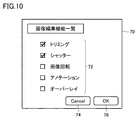
- a panel 70 showing a list of image editing functions as shown in FIG. 10 is displayed on the display 25a.
- the panel 70 displays a plurality of image editing functions 72 and a check box for each image editing function.
- the user can select the image editing function that the edit process for the first image is desired to be applied to the second image.
- the trimming process and the shutter process are selected.
- the OK button 76 the selection can be confirmed.
- the selection can be reset by touching the Cancel button 74.
- the configuration in which the editing process is reflected bidirectionally between the photographed image P1 and the emphasized image P2 has been described, but the reflection method may be selected.
- the reflection method may be selected.
- the editing process for the captured image P1 is reflected on the emphasized image P2 and the editing process for the emphasized image P2 is not reflected on the captured image P1
- the editing process for the emphasized image P2 is reflected on the captured image P1.
- the editing process for the captured image P1 is not reflected in the emphasized image P2
- the editing process for the captured image P1 is reflected in the emphasized image P2 and the editing process for the emphasized image P2 is reflected in the captured image P1.
- the user can select any one of the above three types in advance. Specifically, when the user touches the operation panel 80 displayed in the display area 64, a list of image processing parameters used in the emphasis processing as shown in FIG. 11 is displayed. On the operation panel 80, a plurality of image processing parameters 82 are displayed, and operation buttons 84 for setting the image editing function are also displayed. When the operation button 84 is touched in this state, the operation panel 86 for selecting the above-described reflection method is displayed.
- FIG. 10 In the example of FIG. 10, four options of “captured image ⁇ emphasized image”, “emphasized image ⁇ captured image”, “captured image ⁇ emphasized image”, and “not reflected” are displayed, and a check box is displayed for each option. ..
- the arrows in the options indicate the directions to be reflected.
- “captured image ⁇ emphasized image” indicates that the editing process for the captured image P1 is reflected in the emphasized image P2, and the edit process for the emphasized image P2 is not reflected in the captured image P1.
- the option of "not reflect” indicates that the editing process for the first image is not reflected for the second image.
- the X-ray imaging apparatus may have a mode for applying the editing process executed on the first image to the second image.
- the mode is selected, when the edit process is performed on the first image, the edit process is automatically applied to the second image.
- the mode is deselected, the editing process for the first image is not applied to the second image.
Landscapes
- Health & Medical Sciences (AREA)
- Life Sciences & Earth Sciences (AREA)
- Medical Informatics (AREA)
- Engineering & Computer Science (AREA)
- Radiology & Medical Imaging (AREA)
- Biomedical Technology (AREA)
- Biophysics (AREA)
- Nuclear Medicine, Radiotherapy & Molecular Imaging (AREA)
- Optics & Photonics (AREA)
- Pathology (AREA)
- Physics & Mathematics (AREA)
- High Energy & Nuclear Physics (AREA)
- Heart & Thoracic Surgery (AREA)
- Molecular Biology (AREA)
- Surgery (AREA)
- Animal Behavior & Ethology (AREA)
- General Health & Medical Sciences (AREA)
- Public Health (AREA)
- Veterinary Medicine (AREA)
- Apparatus For Radiation Diagnosis (AREA)
Abstract
X線撮影装置は、被検体にX線を照射するX線照射部と、被検体を透過したX線を検出する検出部と、被検体のX線画像を処理する画像処理部とを備える。画像処理部は、X線画像の画質を調整する画像調整処理と、X線画像および、画像調整処理によるX線画像の調整画像のうちの選択された第1の画像を編集する画像編集処理とを実行するように構成される。画像編集処理において、画像処理部は、第1の画像に対する編集処理を、X線画像および調整画像のうちの非選択の第2の画像に対して適用する。
Description
本発明は、X線撮影装置、画像処理方法および画像処理プログラムに関する。
X線撮影装置の一種である回診用X線撮影装置は、病室間を移動してX線撮影を行なうように構成される。回診用X線撮影装置は、一般に、病状の経過を観察する経過観察だけではなく、術後の残存物(ガーゼ等)の確認およびカテーテル挿入時におけるルートの確認のために用いられる。例えば、医師が被検者にカテーテルを挿入したときに、カテーテルの先端が目的とする位置に配置されているか否かを確認するためのX線撮影を実行する。X線画像においてカテーテルの視認を容易とするために、画像の強調処理が行なわれる。
画像処理の一態様として、国際公開第2009/104459号(特許文献1)には、被検者を撮影し、撮影画像に画像処理を施して診断に適した画質となるようにコントロールするように構成された画像生成装置が開示される。特許文献1では、同一患者の同一部位を時系列に撮影した複数の撮影画像に対して共通の画像処理パラメータを用いて画像処理を施すように構成される。具体的には、階調変換処理(濃度、コントラスト)、周波数強調処理、ダイナミックレンジ圧縮処理などの画像処理パラメータを複数の撮影画像間で一致させることで、複数の撮影画像間で表示基準(各画像の濃度およびコントラスト等)を合わせる。これにより、医師は複数の撮影画像を比較することで、病変部の経時的な変化を観察することが可能となる。
上記特許文献1に記載される経過観察とは異なり、撮影画像を用いて被検者の体内に配されたカテーテルを確認する場合には、被検者のX線撮影により得られたX線画像に対して、カテーテルを強調表示するための画像処理が行なわれることがある。この画像処理パラメータには、X線画像のコントラスト、X線画像のエッジ強調フィルタ係数、X線画像の平滑化フィルタ係数などが含まれる。すなわち、撮影画像の画質を調整する処理を施すことで、カテーテルを視認しやすくする。
さらに、画像処理が施された画像に対しては、トリミング、シャッター、画像の回転/反転、アノテーションおよびオーバーレイなどの編集処理を施すことで、医師が見やすい状態に加工することができる。
しかしながら、一方で、元の撮影画像と、画像処理後の画像とは通常、別々の画像データで構成されているため、画像処理後の画像に対する編集処理は元の撮影画像に対しては反映されない。そのため、2つの画像の間で同じ領域を抜き出して比較したい場合、ユーザは、元の撮影画像および画像処理後の各々に対して同じ編集処理を実行する必要がある。その結果、X線撮影装置の操作性を低下させることが懸念される。
この発明はこのような課題を解決するためになされたものであって、この発明の目的は、X線撮影装置の操作性を向上させることである。
本発明の第1の態様は、被検体にX線を照射するX線照射部と、被検体を透過したX線を検出する検出部と、被検体のX線画像を処理する画像処理部とを備えるX線撮影装置に関する。画像処理部は、X線画像の画質を調整する画像調整処理と、X線画像および、画像調整処理によるX線画像の調整画像のうちの選択された第1の画像を編集する画像編集処理とを実行するように構成される。画像編集処理において、画像処理部は、第1の画像に対する編集処理を、X線画像および調整画像のうちの非選択の第2の画像に対して適用する。
本発明によれば、X線撮影装置の操作性を向上させることができる。
以下、本発明の実施の形態について図面を参照して詳細に説明する。なお、以下図中の同一または相当部分には同一符号を付して、その説明は原則的に繰返さないものとする。
図1は、本実施の形態に係るX線撮影装置の側面概要図である。図2は、本実施の形態に係るX線撮影装置の斜視図である。実施の形態に係るX線撮影装置は、回診用X線撮影装置とも称されるものであり、複数の病室間を移動させて、各病室においてX線検査を実行することが可能に構成されている。
図1を参照して、X線撮影装置は、台車15と、支柱14と、アーム13と、X線管11と、コリメータ12と、ハンドル26と、フラットパネルディテクタ16と、収納部17とを備える。
支柱14は台車15に配設される。アーム13は、支柱14に対して昇降可能な状態で配設される。X線管11は、アーム13の先端に配設される。コリメータ12は、X線管11の下方に配設される。ハンドル26は、コリメータ12に付設される。X線管11およびコリメータ12は「X線照射部」を構成する。フラットパネルディテクタ16は、X線管11から照射され被検者を通過したX線を検出するための「検出部」を構成する。収納部17は、フラットパネルディテクタ16を収納する。
X線撮影装置は、さらに、タッチスクリーン25と、左右一対の前輪21と、左右一対の後輪22と、操作ハンドル19とを備える。
タッチスクリーン25は、フラットパネルディテクタ16により検出されたデジタル画像の表示部とともに、操作者の入力操作を受け付ける入力部として機能する、表示一体型入力装置である。タッチスクリーン25は、タッチパネル式の液晶または有機EL(Electro Luminescence)から構成される。
前輪21は方向変更用の車輪であり、後輪22は駆動用の車輪である。後輪22は台車15内に配設されたモータの駆動により回転する。操作ハンドル19は、台車15の進行方向を操作するためのものである。
アーム13は、図1において実線で示す固定位置と、図1において仮想線で示す撮影位置との間を昇降可能に構成される。固定位置は、台車15を移動させるときのアーム13を配置すべき位置である。撮影位置は固定位置から上昇した位置である。アーム13が固定位置にある状態においては、アーム13の下面はアームキャッチ部と称されるロック部18に当接する。この状態においては、アーム13の下面に配設されたピン23がロック部18に形成された孔部(図示せず)内に収納される。アーム13は、図2に示すように、固定位置から上昇した状態で、支柱14を中心に旋回する。
図3は、本実施の形態に係るX線撮影装置のハードウェア構成の一例を示す図である。図3を参照して、X線撮影装置は、主たる構成要素として、CPU(Central Processing Unit)50と、メモリ52と、通信I/F(Interface)54と、電源回路56と、タッチスクリーン25と、X線照射部10と、フラットパネルディテクタ16とを備える。各構成要素は、図示しないデータバスによって相互に接続されている。
CPU50は、プログラムを実行する。CPU50は、X線撮影装置の各部を統括的に制御する制御部を構成する。制御部の主な制御構成については後述する。
メモリ52は、ROM(Read Only Memory)、RAM(Random Access Memory)および記憶装置により実現される。ROMは、X線撮影装置で実行される制御プログラムを不揮発的に格納する。RAMは、CPU5によるプログラムの実行により生成されたデータ、または入力装置を介して入力されたデータを揮発的に格納する。記憶装置は、例えばフラッシュメモリ等の不揮発性メモリにより構成され、データを不揮発的に格納する。記憶装置に格納されるデータは、X線撮影装置の各部を制御するためのプログラムの他、各種アプリケーションを含んでいる。
通信I/F54は、病院内の無線ネットワークを介して、放射線情報システム(RIS:Radiology Information Systems)100と通信接続されており、放射線情報システム100からX線撮影のオーダー情報を取得する。オーダー情報には、X線管11とフラットパネルディテクタ16との距離(線源・イメージ間距離/SID:Source Image Distance)が含まれている。なお、通信方式としては、例えば、Bluetooth(登録商標)、無線LAN(Local Area Network)等の無線通信であってもよいし、USB(Universal Serial Bus)等を利用した有線通信であってもよい。
電源回路56は、商用電源等の外部電源から電圧の供給を受けてX線撮影蔵置の各部の電源電圧を生成する回路である。
タッチスクリーン25は、ディスプレイ25aおよびタッチパネル25bを有する。ディスプレイ25aは、X線画像を表示するための画面を含んでいる。タッチパネル25bは、操作者の入力操作を受け付ける。X線照射部10は、X線管11およびコリメータ12を有する。フラットパネルディテクタ16は、X線管11から照射され被検者を通過したX線を検出する。
X線撮影装置における処理は、各ハードウェアおよびCPU50により実行されるソフトウェアにより実現される。このようなソフトウェアは、メモリ52に予め格納されている場合がある。また、ソフトウェアは、その他の記憶媒体に格納されて、プログラムプロダクトとして流通している場合もある。あるいは、ソフトウェアは、いわゆるインターネットに接続されている情報提供事業者によってダウンロード可能なプログラムプロダクトとして提供される場合がある。このようなソフトウェアは、読取装置によってその記憶媒体から読み取られて、あるいは通信I/F54等を介してダウンロードされた後、実行可能なプログラムの形式でメモリ52に一旦格納される。当該ソフトウェアは、CPU50によってメモリ52から読み出され、実行可能なプログラムの形式でRAMに格納される。CPU50はそのプログラムを実行する。
CPU50は、機能的構成として、フラットパネルディテクタ16により検出されたX線画像に対して画像処理を行なう画像処理部51を有する。画像処理部51は、画像調整処理と、画像編集処理とを実行可能に構成される。画像調整処理は、X線画像の画質を調整する処理である。画像編集処理は、X線画像を編集する処理である。本願明細書では、画像編集処理は、X線画像の画質の調整を含まないものとする。
図3に示す機能的構成は、基本的には、X線撮影装置のCPU50がメモリ52に格納されたオペレーションシステムおよびアプリケーションプログラムを実行し、X線撮影装置の構成要素へ指示を与えることなどによって実現される。すなわち、CPU50は、X線撮影装置の動作を統括的に制御する制御部としての機能を実現する。
次に、本実施の形態に係るX線撮影装置を使用したX線撮影について説明する。図4は、X線撮影時にディスプレイ25aに表示される画像を示す模式図である。
X線を撮影する場合には、最初に、被検者の下方にフラットパネルディテクタ16を設置するとともに、フラットパネルディテクタ16と対向する位置にX線管11およびコリメータ12からなるX線照射部を配置する。この状態において、X線管11からX線を照射し、被検者を通過したX線をフラットパネルディテクタ16により検出することで、X線を撮影する。
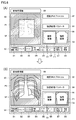
図4(A)を参照して、撮影されたX線画像は、図3に示す画像処理部51により画像処理され、ディスプレイ25aにおけるX線画像の表示領域60に表示される。図4Aでは、表示領域60には、撮影されたX線画像(以下、「撮影画像P1」とも称する)が表示されている。そのため、カテーテルを使用する施術時にX線画像を撮影する場合、撮影画像P1において、体内に配置されたカテーテルは視認が困難な状態となっている。
ディスプレイ25aにはさらに、被検者IDおよびX線の撮影日等の被検者情報を示す表示領域61と、撮影済みプロトコルのリストを示す表示領域62と、表示領域60に表示されたX線画像に対して画像処理を実行するための複数(例えば、8つ)の操作ボタンB1~B8を示す表示領域63とが表示されている。
なお、本願明細書において「プロトコル」とは、一連の設定項目をまとめてプリセットされた手順について定めたものである。「撮影プロトコル」とは、一連のX線撮影における撮影の順序を決定したものである。操作者が表示領域61の撮影済みプロトコルのリストから1つをタッチして選択すると、選択された撮影済みプロトコルでの撮影画像P1が表示領域60に表示される。「タッチ」とは操作者が画面に表示された部分を指等で軽く押すことである。例えば、図4Aでは「胸部 正面(P→A)」の撮影済みプロトコルをタッチすると、被検者の胸部を正面にX線を背部(Posterior)から腹部(Antero)に向けて照射して撮影された胸部正面の撮影画像P1が表示領域60に表示される。
表示領域63に表示される複数の操作ボタンB1~B8には、表示領域60に表示された画像を編集するための操作ボタンB1~B6と、表示領域60に表示された画像の画質を調整するための操作ボタンB7,B8とが含まれる。操作ボタンB1は、「画像編集機能一覧」をディスプレイ25aに表示させるための操作ボタンである。操作ボタンB1をタッチして選択すると、ディスプレイ25aに画像編集機能の一覧を示すパネル(図示せず)が表示される。表示領域63に目的の操作ボタンが表示されていないときには、操作者はこの一覧から目的の操作ボタンを選択することで、目的の操作ボタンを表示領域63に表示させることができる。
操作ボタンB2は、表示領域60に表示された画像を「トリミング」するための操作ボタンである。「トリミング」とは、見たい領域を調整し、出力したいサイズに画像を切り抜く処理である。
操作ボタンB3は、表示領域60に表示された画像に「シャッター」処理をかけるための操作ボタンである。「シャッター」処理とは、照射野領域外(診断対象外の領域)を黒く塗りつぶして出力する処理である。
操作ボタンB4は、表示領域60に表示された画像を「回転/反転」するための操作ボタンである。「画像の回転」とは、表示領域60に表示された画像を反時計回りまたは時計回りに回転する処理である。なお、回転角度は任意の角度に設定することができる。「画像の反転」とは、表示領域60に表示された画像の上下または左右を反転する処理である。
操作ボタンB5は、表示領域60に表示された画像に「アノテーション」を重畳させるための操作ボタンである。「アノテーション」とは、画像の任意の位置に追加できる注釈のことである。アノテーションには、文字情報で構成されたテキストアノテーションと、楕円または矢印等の図形情報で構成された図形アノテーションとが含まれる。
操作ボタンB6は、表示領域60に表示された画像に「オーバーレイ」処理をかけるための操作ボタンである。「オーバーレイ」処理とは、予め設定された項目を画像上に表示させる処理である。例えば、被検者情報、撮影プロトコルおよびX線条件(管電圧、管電流およびX線の照射時間など)に関する情報を項目に設定することができる。
操作ボタンB7は、表示領域60に表示された画像に「強調処理」を実行するための操作ボタンである。「強調処理」は、例えばエッジ強調処理である。
操作ボタンB8は、表示領域60に表示された画像に対して「画像調整」処理を実行するための操作ボタンである。画像調整処理には、「階調処理」、「マルチ周波数処理」、および「ダイナミックレンジ圧縮処理」の少なくとも1つが含まれる。
階調処理とは、入力された画像データを、ディスプレイ25aに表示され又はフィルム等にプリントアウトされた状態において最適な濃度及びコントラストとなるような画像データに変換して出力する処理である。ダイナミックレンジ圧縮処理とは、最も注目している関心領域の濃度およびコントラストを変化させること無く、低露光領域における白抜けや高露光領域における黒つぶれが生じないように画像のダイナミックレンジを可視領域に収める処理である。マルチ周波数処理とは、複数の周波数帯域においてダイナミックレンジ圧縮処理を施すことにより、全空間周波数成分に対してバランス良く強調を加え、さらに強い信号によって発生するオーバーシュートを抑制する処理である。
本願明細書では、画質を調整する処理が実行された撮影画像を「調整画像」とも称する。画質を調整する処理には、以下に説明する強調処理が含まれる。言い換えれば、強調処理は、撮影画像の画質を調整する画像調整処理の一態様に相当する。
(強調処理)
図4(A)の状態で、操作ボタンB7(強調処理)がタッチされると、表示領域60に表示された撮影画像P1に対して強調処理が実行される。具体的には、プロトコルに予め設定されている強調処理パラメータを用いて、撮影画像P1に対する画像処理が実行される。以下の説明では、強調処理が実行された撮影画像を「強調画像P2」とも称する。強調画像P2は、「調整画像」の一実施例に対応する。
図4(A)の状態で、操作ボタンB7(強調処理)がタッチされると、表示領域60に表示された撮影画像P1に対して強調処理が実行される。具体的には、プロトコルに予め設定されている強調処理パラメータを用いて、撮影画像P1に対する画像処理が実行される。以下の説明では、強調処理が実行された撮影画像を「強調画像P2」とも称する。強調画像P2は、「調整画像」の一実施例に対応する。
図4(B)に示すように、ディスプレイ25aの表示領域60には、強調画像P2が表示される。表示領域60の右側の表示領域66には、撮影画像P1のサムネイルS1および強調画像P2のサムネイルS2が表示される。図4Bでは、強調画像のサムネイルS2をタッチして選択すると、表示領域60には強調画像P2が表示される。なお、サムネイルS2は、選択状態であることを示すために、枠F1で囲まれる。すなわち、強調画像P2は「第1の画像」に対応し、撮影画像P1は「第2の画像」に対応する。
なお、この状態で、撮影画像のサムネイルS1をタッチして選択すると、表示領域60の画像は強調画像P2から撮影画像P1に切り替わるとともに、サムネイルS1が枠F1で囲まれる。すなわち、撮影画像P1は「第1の画像」に対応し、強調画像P2は「第2の画像」に対応する。
表示領域60の右側の表示領域64には、強調処理パラメータを編集するための操作パネルが表示される。図示は省略するが、操作パネルをタッチすると、強調処理で使用する画像処理パラメータの一覧が表示される。操作者は、この一覧から画像処理パラメータを選択し、編集することができる。強調処理パラメータには、階調処理、ダイナミックレンジ圧縮処理およびマルチ周波数処理の少なくとも1つに関するパラメータが含まれる。
撮影画像P1に対して強調処理(例えば、エッジ強調処理)を実行することにより、被検者の体内に配されたガーゼまたはカテーテルなどを強調して表示することができる。これにより、ガーゼの残存またはカテーテルの位置を確認しやすくなる。
ここで、表示領域60に表示された強調画像P2に対しては、表示領域63に表示された操作ボタンB2~B6を操作することによって、上述したトリミング、シャッター、画像の回転/反転、アノテーションおよびオーバーレイなどの編集処理を施すことができる。
しかしながら、一方で、強調画像P2と撮影画像P1とは別々の画像データで構成されているため、強調画像P2に対する編集処理と、撮影画像P1に対する編集処理とは、互いに独立した処理として扱われる。したがって、強調画像P2に対して編集処理を実行した後、表示領域60に表示される画像を強調画像P2から撮影画像P1に切り替えた場合、編集処理が施されていない撮影画像P1が表示されることになる。そのため、強調画像P2と撮影画像P1とで同じ領域を抜き出して比較したい場合、操作者は、撮影画像P1に対して強調画像P2に対して行なった編集処理と同様の編集処理を実行する必要がある。その結果、X線撮影装置の操作性を低下させることが懸念される。
そこで、本実施の形態では、撮影画像P1および強調画像P2のうち選択された一方の画像に対して実行された編集処理を、非選択の他方の画像に対しても適用する構成とする。これによると、一方の画像に対して実行した編集処理を、他方の画像に対しても自動的に反映させることができるため、他方の画像に対する編集処理が不要となる。したがって、X線撮影装置の操作性を向上させることができる。
(画像編集処理)
以下、本実施の形態に係るX線撮影装置における画像編集処理について、具体例を挙げて説明する。
以下、本実施の形態に係るX線撮影装置における画像編集処理について、具体例を挙げて説明する。
(1)トリミング処理
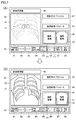
図5(A)を参照して、ディスプレイ25aの表示領域60には強調画像P2が表示されている。この状態で、操作ボタンB2(トリミング)がタッチされると、強調画像P2に対してトリミング処理が実行される。具体的には、図5(A)に示すように、強調画像P2上に、トリミング枠TFが重畳して表示される。トリミング枠TFは、例えば矩形形状を有しており、表示領域60内を移動させることができる。また、トリミング枠TFを形成する4辺を互いに独立して動かすことで、トリミング枠TFのサイズを調整することができる。なお、トリミング枠TFの移動は、表示領域60に表示されたポインタ(図示せず)を上下または左右方向にドラッグすることで行なうことができる。トリミング枠TFの各辺に表示されたカーソル(図示せず)をタッチすることで各辺が移動し、トリミング枠TFを再設定することができる。あるいは、予め設定されている定型サイズの一覧からサイズを選択することで、トリミング枠TFのサイズを定型サイズに調整することができる。なお、トリミング枠TFの形状は、閉じられた形状であれば、矩形形状以外の形状(例えば、円形または多角形)であってもよい。
図5(A)を参照して、ディスプレイ25aの表示領域60には強調画像P2が表示されている。この状態で、操作ボタンB2(トリミング)がタッチされると、強調画像P2に対してトリミング処理が実行される。具体的には、図5(A)に示すように、強調画像P2上に、トリミング枠TFが重畳して表示される。トリミング枠TFは、例えば矩形形状を有しており、表示領域60内を移動させることができる。また、トリミング枠TFを形成する4辺を互いに独立して動かすことで、トリミング枠TFのサイズを調整することができる。なお、トリミング枠TFの移動は、表示領域60に表示されたポインタ(図示せず)を上下または左右方向にドラッグすることで行なうことができる。トリミング枠TFの各辺に表示されたカーソル(図示せず)をタッチすることで各辺が移動し、トリミング枠TFを再設定することができる。あるいは、予め設定されている定型サイズの一覧からサイズを選択することで、トリミング枠TFのサイズを定型サイズに調整することができる。なお、トリミング枠TFの形状は、閉じられた形状であれば、矩形形状以外の形状(例えば、円形または多角形)であってもよい。
以上の処理を行なうことにより、強調画像P2とトリミング枠TFとが重なった領域が切り取られて、トリミング処理された画像となって出力される。
この状態で、撮影画像のサムネイルS1をタッチして選択すると、図5(B)に示すように、表示領域60には強調画像P2に代えて、撮影画像P1が表示される。表示領域60にはさらに、図5(A)のトリミング枠TFと同一の形状を有するトリミング枠TFが重畳して表示される。図5(B)のトリミング枠TFの位置は、図5(A)のトリミング枠TFの位置と同じである。すなわち、強調画像P2に対して実行したトリミング処理が、撮影画像P1に対しても自動的に実行される。この結果、強調画像P2と撮影画像P1とで同じ領域が切り取られて出力されることになる。
(2)シャッター処理
図6(A)を参照して、ディスプレイ25aの表示領域60には、撮影画像P1が表示されている。この状態で、操作ボタンB3(シャッター)がタッチされると、撮影画像P1に対してシャッター処理が実行される。具体的には、図6(A)に示すように、撮影画像P1上にシャッター枠SFが重畳して表示される。シャッター枠SFは、例えば矩形形状を有しており、その外周が黒く塗りつぶされている。したがって、撮影画像P1は、シャッター枠SFで囲まれた領域のみが表示される。
図6(A)を参照して、ディスプレイ25aの表示領域60には、撮影画像P1が表示されている。この状態で、操作ボタンB3(シャッター)がタッチされると、撮影画像P1に対してシャッター処理が実行される。具体的には、図6(A)に示すように、撮影画像P1上にシャッター枠SFが重畳して表示される。シャッター枠SFは、例えば矩形形状を有しており、その外周が黒く塗りつぶされている。したがって、撮影画像P1は、シャッター枠SFで囲まれた領域のみが表示される。
シャッター枠SFは、表示領域60内を移動させることができる。また、シャッター枠SFの各頂点を動かすことで、シャッター枠SFのサイズを調整することができる。なお、シャッター枠SFの移動は、表示領域60に表示されたポインタ(図示せず)を上下方向または左右方向にドラッグすることで行なうことができる。シャッター枠SFの各頂点に表示されたカーソル(図示せず)をタッチすることで各頂点が移動し、シャッター枠SFを再設定することができる。なお、シャッター枠SFの形状は、閉じられた形状であれば、矩形形状以外の形状(例えば、円形または多角形)であってもよい。
この状態で、強調画像のサムネイルS2をタッチして選択すると、図6(B)に示すように、表示領域60には撮影画像P1に代えて、強調画像P2が表示される。表示領域60にはさらに、図6(A)のシャッター枠SFと同一の形状を有するシャッター枠SFが重畳して表示される。図6(B)のシャッター枠SFの位置は、図6(A)のシャッター枠SFの位置と同じである。すなわち、撮影画像P1に対して実行したシャッター処理が、強調画像P2に対しても自動的に実行される。この結果、撮影画像P1と強調画像P2とで同じ領域が黒く塗りつぶされて出力されることになる。
(3)アノテーション処理
図7(A)を参照して、ディスプレイ25aの表示領域60には、撮影画像P1が表示されている。この状態で、操作ボタンB5(アノテーション)がタッチされると、撮影画像P1に対してアノテーション処理が実行される。具体的には、図7(A)に示すように、撮影画像P1上にアノテーションA1が重畳して表示される。図7(A)の例では、“test”の4文字からなるテキストアノテーションA1が重畳して表示されている。テキストアノテーションA1には、所定の文字数以下の文字を入力することができる。
図7(A)を参照して、ディスプレイ25aの表示領域60には、撮影画像P1が表示されている。この状態で、操作ボタンB5(アノテーション)がタッチされると、撮影画像P1に対してアノテーション処理が実行される。具体的には、図7(A)に示すように、撮影画像P1上にアノテーションA1が重畳して表示される。図7(A)の例では、“test”の4文字からなるテキストアノテーションA1が重畳して表示されている。テキストアノテーションA1には、所定の文字数以下の文字を入力することができる。
テキストアノテーションA1は、表示領域60内の任意の位置に配置することができる。例えば、撮影画像P1上のテキストアノテーションA1を配置したい位置をタッチすると、その位置にテキストアノテーションA1を配置することができる。
図示は省略するが、撮影画像P1上に、楕円または矢印等の図形アノテーションを配置することもできる。テキストアノテーションおよび図形アノテーションのサイズは調整することができる。
この状態で、強調画像のサムネイルS2をタッチして選択すると、図7(B)に示すように、表示領域60には撮影画像P1に代えて、強調画像P2が表示される。表示領域60にはさらに、図7(A)のテキストアノテーションA1と同一のテキストアノテーションA1が重畳して表示される。図7(B)のテキストアノテーションA1の位置は、図7AのテキストアノテーションA1の位置と同じである。すなわち、撮影画像P1に対して実行したアノテーション処理が、強調画像P2に対しても自動的に実行される。この結果、撮影画像P1と強調画像P2とで同じ位置に同じ内容のアノテーションが重畳されて出力されることになる。
(4)オーバーレイ処理
図8(A)を参照して、ディスプレイ25aの表示領域60には、撮影画像P1が表示されている。この状態で、操作ボタンB6(オーバーレイ)がタッチされると、撮影画像P1に対してオーバーレイ処理が実行される。具体的には、図8Aに示すように、撮影画像P1上に予め設定された項目O1,O2が重畳して表示される。図8(A)の例では、被検者情報を示す項目O1および撮影プロトコル(X線条件)を示す項目O2が重畳して表示されている。
図8(A)を参照して、ディスプレイ25aの表示領域60には、撮影画像P1が表示されている。この状態で、操作ボタンB6(オーバーレイ)がタッチされると、撮影画像P1に対してオーバーレイ処理が実行される。具体的には、図8Aに示すように、撮影画像P1上に予め設定された項目O1,O2が重畳して表示される。図8(A)の例では、被検者情報を示す項目O1および撮影プロトコル(X線条件)を示す項目O2が重畳して表示されている。
項目O1,O2は、表示領域60内の任意の位置に配置することができる。例えば、撮影画像P1上の項目O1,O2を配置したい位置をタッチすると、その位置に項目O1,O2を配置することができる。
この状態で、強調画像のサムネイルS2をタッチして選択すると、図8(B)に示すように、表示領域60には撮影画像P1に代えて、強調画像P2が表示される。表示領域60にはさらに、図8(A)の項目O1,O2と同一の項目O1,O2が重畳して表示される。図8(B)の項目O1,O2の位置は、図8(A)の項目O1,O2の位置と同じである。すなわち、撮影画像P1に対して実行したオーバーレイ処理が、強調画像P2に対しても自動的に実行される。この結果、撮影画像P1と強調画像P2とで同じ位置に同じ内容の項目が重畳されて出力されることになる。
(5)画像の回転/反転処理
図示は省略するが、ディスプレイ25aの表示領域60に撮影画像P1が表示されている状態で操作ボタンB4(画像回転)がタッチされると、撮影画像P1の回転または反転が実行される。撮影画像P1は、予め設定された角度で時計回りまたは反時計回りに回転する。または、撮影画像P1の上下または左右が反転する。
図示は省略するが、ディスプレイ25aの表示領域60に撮影画像P1が表示されている状態で操作ボタンB4(画像回転)がタッチされると、撮影画像P1の回転または反転が実行される。撮影画像P1は、予め設定された角度で時計回りまたは反時計回りに回転する。または、撮影画像P1の上下または左右が反転する。
この状態で、強調画像のサムネイルS2をタッチして選択すると、表示領域60には撮影画像P1に代えて、強調画像P2が表示される。強調画像P2は、撮影画像P1と同じ角度だけ回転している。または、強調画像P2は、撮影画像P1を同じ態様で反転している。すなわち、撮影画像P1に対して実行した画像の回転または画像の反転が、強調画像P2に対しても自動的に実行される。
なお、図6から図8では、撮影画像P1に対して実行した編集処理が、強調画像P2に対して自動的に適用される構成について説明したが、表示領域60に表示された強調画像P2に対して編集処理を実行した場合には、当該編集処理を撮影画像P1に対しても自動的に適用することができる。
(フローチャート)
以上に説明した画像処理は、図9に示すフローチャートにまとめることができる。
以上に説明した画像処理は、図9に示すフローチャートにまとめることができる。
図9を参照して、X線撮影装置において被検者のX線画像が撮影されると、ステップS01では、画像処理部51は、ディスプレイ25aに撮影画像P1を表示する。この状態で、画像処理部51は、ステップS02により、強調処理の実行が指示されたか否かを判定する。強調処理の実行が指示されていなければ(S02にてNO)、画像処理部51はステップS03以降の処理をスキップして処理を終了する。
一方、強調処理の実行が指示されていれば(S02にてYES)、画像処理部51は、ステップS03により、撮影画像P1に対して強調処理を実行することにより、強調画像P2を生成する。
次に、画像処理部51は、ステップS04により、撮影画像P1のサムネイルS1および強調画像P2のサムネイルS2をディスプレイ25aの表示領域66に表示する。画像処理部51は、ステップS05にて、強調画像のサムネイルS2を選択する操作(タッチ操作)がなされたか否かを判定する。
強調画像のサムネイルS2を選択する操作がなされた場合(S05にてYES)、画像処理部51は、ステップS06に進み、表示領域60に強調画像P2を表示する。一方、強調画像のサムネイルS2を選択する操作がなされなかった場合(S05にてNO)、画像処理部51は、ステップS07に進み、表示領域60に撮影画像P1を表示する。
次に、ステップS08により、画像処理部51は、表示領域60に表示された画像を編集する処理が指示されたか否かを判定する。具体的には、画像処理部51は、表示領域63に表示された操作ボタンB2~B6のいずれかがタッチされたか否かを判定する。
画像の編集処理が指示された場合(S08にてYES)、画像処理部51は、ステップS09に進み、撮影画像P1および強調画像P2の双方に対して、操作者より指示された編集処理を実行する。
ステップS11では、画像処理部51は、ディスプレイ25aの表示領域60に表示されている画像が強調画像P2であるか否かを判定する。表示領域60に表示されている画像が強調画像P2である場合(S11にてYES)、画像処理部51は、ステップS12に進み、編集処理が施された強調画像P2を表示領域60に表示する。一方、表示領域60に表示されている画像が撮影画像P1である場合(S11にてNO)、画像処理部51は、ステップS13に進み、編集処理が施された撮影画像P1を表示領域60に表示する。画像処理部51はさらに、ステップS14により、編集処理が施された撮影画像P1および強調画像P2をメモリ52に保存する。
以上説明したように、本実施の形態に係るX線撮影装置によれば、撮影画像および強調画像のうちの選択された第1の画像に対する編集処理を、非選択の第2の画像に自動的に反映させることができるため、第1の画像および第2の画像の双方に対して同じ編集処理を簡易に行なうことができる。したがって、X線撮影装置の操作性を向上させることができる。
[変形例]
(1)上述した実施の形態では、第1の画像に対して実行された編集処理を第2の画像に対して適用する構成について説明したが、第2の画像への編集処理の適用の可否を選択するように構成してもよい。例えば、ユーザは、X線撮影装置が有する複数の画像編集機能の各々に対して、第2の画像への適用の可否を予め設定しておくことができる。
(1)上述した実施の形態では、第1の画像に対して実行された編集処理を第2の画像に対して適用する構成について説明したが、第2の画像への編集処理の適用の可否を選択するように構成してもよい。例えば、ユーザは、X線撮影装置が有する複数の画像編集機能の各々に対して、第2の画像への適用の可否を予め設定しておくことができる。
具体的には、ユーザが表示領域63に表示された操作ボタンB1をタッチすると、ディスプレイ25aには、図10に示すような画像編集機能の一覧を示すパネル70が表示される。パネル70には、複数の画像編集機能72が表示されるとともに、画像編集機能ごとにチェックボックスが表示されている。ユーザは、チェックボックスにチェックを入力することにより、第1の画像に対する編集処理を第2の画像に適用したい画像編集機能を選択することができる。図10の例では、トリミング処理およびシャッター処理が選択されている。この状態で、OKボタン76をタッチすることにより、選択を確定することができる。あるいは、Cancelボタン74をタッチすることにより、選択をリセットすることができる。
(2)上述した実施の形態では、撮影画像P1と強調画像P2との間で編集処理を双方向に反映させる構成について説明したが、反映のさせ方について選択するように構成してもよい。反映のさせ方には、撮影画像P1に対する編集処理を強調画像P2に反映し、強調画像P2に対する編集処理を撮影画像P1には反映させない場合、強調画像P2に対する編集処理を撮影画像P1に反映し、撮影画像P1に対する編集処理を強調画像P2に反映させない場合、および、撮影画像P1に対する編集処理を強調画像P2に反映し、強調画像P2に対する編集処理を撮影画像P1に反映する場合の3通りがある。
例えば、ユーザは、上記3通りのうちのいずれかを予め選択しておくことができる。具体的には、ユーザが表示領域64に表示された操作パネル80をタッチすると、図11に示すような強調処理で使用する画像処理パラメータの一覧が表示される。操作パネル80には、複数の画像処理パラメータ82が表示されるとともに、画像編集機能を設定するための操作ボタン84が表示される。この状態で操作ボタン84をタッチすると、上述した反映のさせ方を選択するための操作パネル86が表示される。
図10の例では、「撮影画像→強調画像」、「強調画像→撮影画像」、「撮影画像⇔強調画像」および「反映させない」の4つの選択肢とともに、選択肢ごとにチェックボックスが表示されている。なお、選択肢中の矢印は反映させる向きを表している。例えば「撮影画像→強調画像」は、撮影画像P1に対する編集処理を強調画像P2に反映し、強調画像P2に対する編集処理を撮影画像P1には反映させないことを表している。また、「反映させない」という選択肢は、第1の画像に対する編集処理を第2の画像に反映させないことを表している。ユーザは、チェックボックスにチェックを入力することにより、4つの選択肢から反映のさせ方を選択することができる。
(3)本実施の形態に係るX線撮影装置は、第1の画像に対して実行された編集処理を第2の画像に対して適用するためのモードを有していてもよい。当該モードが選択されている場合、第1の画像に対して編集処理が実行されると、当該編集処理が第2の画像に対して自動的に適用される。当該モードが非選択になると、第1の画像に対する編集処理は第2の画像には適用されない。
なお、以上の述べた実施の形態および変形例に記載した構成を、技術的に矛盾のない範囲で適宜組み合わせるように適用してもよい。
今回開示された実施の形態はすべての点で例示であって制限的なものではないと考えられるべきである。本発明の範囲は上記した説明ではなくて請求の範囲によって示され、請求の範囲と均等の意味および範囲内でのすべての変更が含まれることが意図される。
10 X線照射部、11 X線管、12 コリメータ、13 アーム、14 支柱、15 台車、16 フラットパネルディテクタ、17 収納部、18 ロック部、19 操作ハンドル、21 前輪、22 後輪、23 ピン、25 タッチスクリーン、25a ディスプレイ、25b タッチパネル、26 ハンドル、50 CPU、51 画像処理部、52 メモリ、54 通信I/F、56 電源回路、60,61,62,63,64,66 表示領域、70 パネル、80,86 操作パネル、82 画像処理パラメータ、100 放射線情報システム、B1~B8 操作ボタン、P1 撮影画像、P2 強調画像(調整画像)、S1,S2 サムネイル、TF トリミング枠、SF シャッター枠、A1 テキストアノテーション、O1,O2 項目。
Claims (8)
- 被検体にX線を照射するX線照射部と、
前記被検体を透過したX線を検出する検出部と、
前記被検体のX線画像を処理する画像処理部とを備え、
前記画像処理部は、
前記X線画像の画質を調整する画像調整処理と、
前記X線画像および、前記画像調整処理による前記X線画像の調整画像のうちの選択された第1の画像を編集する画像編集処理とを実行するように構成され、
前記画像編集処理において、前記画像処理部は、前記第1の画像に対する編集処理を、前記X線画像および前記調整画像のうちの非選択の第2の画像に対して適用する、X線撮影装置。 - 前記画像調整処理において、前記画像処理部は、前記X線画像に対して、強調処理、階調処理、マルチ周波数処理およびダイナミックレンジ圧縮処理の少なくとも1つを実行するように構成され、
前記画像編集処理において、前記画像処理部は、前記第1の画像に対して、トリミング、シャッター、アノテーション、オーバーレイおよび、画像回転/反転のうちの少なくとも1つの編集処理を実行するように構成される、請求項1に記載のX線撮影装置。 - ユーザ操作を受け付ける入力部をさらに備え、
前記入力部は、前記第2の画像への前記編集処理の適用の可否を選択するための操作を受け付ける、請求項1に記載のX線撮影装置。 - 前記画像編集処理において、前記画像処理部は、前記第1の画像に対して、トリミング、シャッター、アノテーション、オーバーレイおよび、画像の回転/反転のうちの2以上の編集処理を実行するように構成され、
ユーザ操作を受け付ける入力部をさらに備え、
前記入力部は、前記2以上の編集処理のうち前記第2の画像に適用する編集処理を選択するための操作を受け付ける、請求項1に記載のX線撮影装置。 - 前記画像処理部は、前記第2の画像に対して前記編集処理を適用する第1のモードと、前記第2の画像に対して前記編集処理を適用しない第2のモードとを有しており、
ユーザ操作を受け付ける入力部をさらに備え、
前記入力部は、前記第1のモードおよび前記第2のモードを切り替えるための操作を受け付ける、請求項1に記載のX線撮影装置。 - ユーザ操作を受け付ける入力部をさらに備え、
前記入力部は、前記X線画像および前記調整画像のうちから前記第1の画像を選択するための操作を受け付ける、請求項1に記載のX線撮影装置。 - 被検体のX線画像を処理する画像処理方法であって、
前記X線画像の画質を調整するステップと、
前記X線画像および、前記画質を調整するステップによる前記X線画像の調整画像のうちの選択された第1の画像を編集するステップと、
前記第1の画像に対する編集処理を、前記X線画像および前記調整画像のうちの非選択の第2の画像に対して適用するステップとを備える、画像処理方法。 - コンピュータに、被検体のX線画像を画像処理を実行させるための画像処理プログラムであって、
前記X線画像の画質を調整するステップと、
前記X線画像および、前記画質を調整するステップによる前記X線画像の調整画像のうちの選択された第1の画像を編集するステップと、
前記第1の画像に対する編集処理を、前記X線画像および前記調整画像のうちの非選択の第2の画像に対して適用するステップとを前記コンピュータに実行させる、画像処理プログラム。
Priority Applications (1)
| Application Number | Priority Date | Filing Date | Title |
|---|---|---|---|
| PCT/JP2019/007107 WO2020174543A1 (ja) | 2019-02-25 | 2019-02-25 | X線撮影装置、画像処理方法および画像処理プログラム |
Applications Claiming Priority (1)
| Application Number | Priority Date | Filing Date | Title |
|---|---|---|---|
| PCT/JP2019/007107 WO2020174543A1 (ja) | 2019-02-25 | 2019-02-25 | X線撮影装置、画像処理方法および画像処理プログラム |
Publications (1)
| Publication Number | Publication Date |
|---|---|
| WO2020174543A1 true WO2020174543A1 (ja) | 2020-09-03 |
Family
ID=72238319
Family Applications (1)
| Application Number | Title | Priority Date | Filing Date |
|---|---|---|---|
| PCT/JP2019/007107 WO2020174543A1 (ja) | 2019-02-25 | 2019-02-25 | X線撮影装置、画像処理方法および画像処理プログラム |
Country Status (1)
| Country | Link |
|---|---|
| WO (1) | WO2020174543A1 (ja) |
Citations (6)
| Publication number | Priority date | Publication date | Assignee | Title |
|---|---|---|---|---|
| JP2005130928A (ja) * | 2003-10-28 | 2005-05-26 | Canon Inc | 画像表示装置、画像表示方法及びそのプログラム |
| JP2007089871A (ja) * | 2005-09-29 | 2007-04-12 | Hitachi Medical Corp | 医用画像処理装置 |
| WO2009104459A1 (ja) * | 2008-02-19 | 2009-08-27 | コニカミノルタエムジー株式会社 | 小規模施設用診断支援装置及びプログラム |
| JP2013198683A (ja) * | 2012-03-26 | 2013-10-03 | Canon Inc | 撮影システム及びその制御方法、並びに、プログラム |
| JP2015085189A (ja) * | 2013-09-25 | 2015-05-07 | 富士フイルム株式会社 | 画像処理装置、画像処理システム、画像処理プログラム、及び画像処理方法 |
| JP2016137007A (ja) * | 2015-01-26 | 2016-08-04 | コニカミノルタ株式会社 | 画像表示装置及び画像表示方法 |
-
2019
- 2019-02-25 WO PCT/JP2019/007107 patent/WO2020174543A1/ja active Application Filing
Patent Citations (6)
| Publication number | Priority date | Publication date | Assignee | Title |
|---|---|---|---|---|
| JP2005130928A (ja) * | 2003-10-28 | 2005-05-26 | Canon Inc | 画像表示装置、画像表示方法及びそのプログラム |
| JP2007089871A (ja) * | 2005-09-29 | 2007-04-12 | Hitachi Medical Corp | 医用画像処理装置 |
| WO2009104459A1 (ja) * | 2008-02-19 | 2009-08-27 | コニカミノルタエムジー株式会社 | 小規模施設用診断支援装置及びプログラム |
| JP2013198683A (ja) * | 2012-03-26 | 2013-10-03 | Canon Inc | 撮影システム及びその制御方法、並びに、プログラム |
| JP2015085189A (ja) * | 2013-09-25 | 2015-05-07 | 富士フイルム株式会社 | 画像処理装置、画像処理システム、画像処理プログラム、及び画像処理方法 |
| JP2016137007A (ja) * | 2015-01-26 | 2016-08-04 | コニカミノルタ株式会社 | 画像表示装置及び画像表示方法 |
Similar Documents
| Publication | Publication Date | Title |
|---|---|---|
| JP4901159B2 (ja) | X線ct装置及びx線撮影方法 | |
| JP6260615B2 (ja) | 診断提供用医用画像システム及び一般撮影用の診断提供用医用画像システムにタルボ撮影装置系を導入する方法 | |
| JP6519663B2 (ja) | 表示装置およびx線ct装置 | |
| US9888892B2 (en) | X-ray diagnostic imaging apparatus | |
| JP2002200062A (ja) | X線画像撮影装置及び方法、制御装置及び方法 | |
| US20140037057A1 (en) | X-ray imaging apparatus, and method of setting imaging area of x-ray imaging apparatus | |
| CN103126697B (zh) | X射线图像诊断装置 | |
| JP6766829B2 (ja) | 放射線画像撮影システム、医用画像出力システムおよび出力装置 | |
| CN105307572B (zh) | 控制装置、摄像装置、摄像系统和控制方法 | |
| JP2023139295A (ja) | X線撮影装置およびx線撮影方法 | |
| JP5595184B2 (ja) | 放射線画像撮影装置および放射線画像撮影方法 | |
| JP2009070074A (ja) | 画像処理装置および画像処理プログラム | |
| WO2020174543A1 (ja) | X線撮影装置、画像処理方法および画像処理プログラム | |
| JP2016202329A (ja) | 被爆線量算出装置及び被爆線量管理システム、並びに、それらの制御方法及びそのプログラム | |
| JP2011224086A (ja) | 画像処理装置、x線撮影装置、画像表示方法、画像比較方法、および画像表示プログラム | |
| JP6033267B2 (ja) | 画像処理装置、画像処理システム、画像処理プログラム、及び画像処理方法 | |
| JP2015080555A (ja) | 医用画像処理装置及びプログラム | |
| JP7094691B2 (ja) | 放射線撮影システム、放射線撮影方法、制御装置及びプログラム | |
| JP2010179092A (ja) | 断層撮影装置及び断層撮影方法 | |
| JP6183183B2 (ja) | X線透視装置 | |
| JP4661209B2 (ja) | 医用画像出力システム | |
| JP2021094219A (ja) | 画像処理方法、画像処理装置及びプログラム | |
| WO2021187188A1 (ja) | 放射線撮影システム、画像処理方法、及びプログラム | |
| JPWO2019003506A1 (ja) | 断層像生成方法および放射線撮影装置 | |
| JP2012000125A (ja) | 放射線撮影装置 |
Legal Events
| Date | Code | Title | Description |
|---|---|---|---|
| 121 | Ep: the epo has been informed by wipo that ep was designated in this application |
Ref document number: 19917311 Country of ref document: EP Kind code of ref document: A1 |
|
| NENP | Non-entry into the national phase |
Ref country code: DE |
|
| 122 | Ep: pct application non-entry in european phase |
Ref document number: 19917311 Country of ref document: EP Kind code of ref document: A1 |
|
| NENP | Non-entry into the national phase |
Ref country code: JP |