WO2020173429A1 - 检测电路及方法 - Google Patents
检测电路及方法 Download PDFInfo
- Publication number
- WO2020173429A1 WO2020173429A1 PCT/CN2020/076601 CN2020076601W WO2020173429A1 WO 2020173429 A1 WO2020173429 A1 WO 2020173429A1 CN 2020076601 W CN2020076601 W CN 2020076601W WO 2020173429 A1 WO2020173429 A1 WO 2020173429A1
- Authority
- WO
- WIPO (PCT)
- Prior art keywords
- switch module
- main
- positive
- negative
- battery pack
- Prior art date
- Legal status (The legal status is an assumption and is not a legal conclusion. Google has not performed a legal analysis and makes no representation as to the accuracy of the status listed.)
- Ceased
Links
Classifications
-
- G—PHYSICS
- G01—MEASURING; TESTING
- G01R—MEASURING ELECTRIC VARIABLES; MEASURING MAGNETIC VARIABLES
- G01R27/00—Arrangements for measuring resistance, reactance, impedance, or electric characteristics derived therefrom
- G01R27/02—Measuring real or complex resistance, reactance, impedance, or other two-pole characteristics derived therefrom, e.g. time constant
- G01R27/025—Measuring very high resistances, e.g. isolation resistances, i.e. megohm-meters
-
- H—ELECTRICITY
- H02—GENERATION; CONVERSION OR DISTRIBUTION OF ELECTRIC POWER
- H02J—ELECTRIC POWER NETWORKS; CIRCUIT ARRANGEMENTS OR SYSTEMS FOR SUPPLYING OR DISTRIBUTING ELECTRIC POWER; SYSTEMS FOR STORING ELECTRIC ENERGY
- H02J7/00—Circuit arrangements for charging or discharging batteries or for supplying loads from batteries
- H02J7/60—Circuit arrangements for charging or discharging batteries or for supplying loads from batteries including safety or protection arrangements
- H02J7/663—Circuit arrangements for charging or discharging batteries or for supplying loads from batteries including safety or protection arrangements using battery or load disconnect circuits
-
- G—PHYSICS
- G01—MEASURING; TESTING
- G01R—MEASURING ELECTRIC VARIABLES; MEASURING MAGNETIC VARIABLES
- G01R27/00—Arrangements for measuring resistance, reactance, impedance, or electric characteristics derived therefrom
- G01R27/02—Measuring real or complex resistance, reactance, impedance, or other two-pole characteristics derived therefrom, e.g. time constant
- G01R27/14—Measuring resistance by measuring current or voltage obtained from a reference source
-
- G—PHYSICS
- G01—MEASURING; TESTING
- G01R—MEASURING ELECTRIC VARIABLES; MEASURING MAGNETIC VARIABLES
- G01R31/00—Arrangements for testing electric properties; Arrangements for locating electric faults; Arrangements for electrical testing characterised by what is being tested not provided for elsewhere
- G01R31/50—Testing of electric apparatus, lines, cables or components for short-circuits, continuity, leakage current or incorrect line connections
- G01R31/52—Testing for short-circuits, leakage current or ground faults
-
- H—ELECTRICITY
- H02—GENERATION; CONVERSION OR DISTRIBUTION OF ELECTRIC POWER
- H02J—ELECTRIC POWER NETWORKS; CIRCUIT ARRANGEMENTS OR SYSTEMS FOR SUPPLYING OR DISTRIBUTING ELECTRIC POWER; SYSTEMS FOR STORING ELECTRIC ENERGY
- H02J7/00—Circuit arrangements for charging or discharging batteries or for supplying loads from batteries
- H02J7/90—Regulation of charging or discharging current or voltage
-
- G—PHYSICS
- G01—MEASURING; TESTING
- G01R—MEASURING ELECTRIC VARIABLES; MEASURING MAGNETIC VARIABLES
- G01R19/00—Arrangements for measuring currents or voltages or for indicating presence or sign thereof
- G01R19/165—Indicating that current or voltage is either above or below a predetermined value or within or outside a predetermined range of values
- G01R19/16533—Indicating that current or voltage is either above or below a predetermined value or within or outside a predetermined range of values characterised by the application
- G01R19/16538—Indicating that current or voltage is either above or below a predetermined value or within or outside a predetermined range of values characterised by the application in AC or DC supplies
- G01R19/16542—Indicating that current or voltage is either above or below a predetermined value or within or outside a predetermined range of values characterised by the application in AC or DC supplies for batteries
-
- G—PHYSICS
- G01—MEASURING; TESTING
- G01R—MEASURING ELECTRIC VARIABLES; MEASURING MAGNETIC VARIABLES
- G01R31/00—Arrangements for testing electric properties; Arrangements for locating electric faults; Arrangements for electrical testing characterised by what is being tested not provided for elsewhere
- G01R31/327—Testing of circuit interrupters, switches or circuit-breakers
- G01R31/3277—Testing of circuit interrupters, switches or circuit-breakers of low voltage devices, e.g. domestic or industrial devices, such as motor protections, relays, rotation switches
- G01R31/3278—Testing of circuit interrupters, switches or circuit-breakers of low voltage devices, e.g. domestic or industrial devices, such as motor protections, relays, rotation switches of relays, solenoids or reed switches
Definitions
- the embodiments of the present application relate to the field of circuit technology, and in particular, to a detection circuit and method.
- the power battery pack is a key component of an electric vehicle.
- the two sides of the electric vehicle's relay are grounded separately. When the relay is closed, the insulation performance of the electric vehicle will be tested to ensure the safety of high-voltage power.
- the purpose of the embodiments of the present application is to provide a detection circuit and method that can detect the insulation resistance of the outer side of the main positive switch module to the reference potential terminal and the insulation resistance of the outer side of the main negative switch module to the reference potential terminal to obtain the main positive switch
- the insulation performance between the module and the outside of the main negative switch module prevents dangerous contact.
- an embodiment of the present application provides a detection circuit, including: a controller, a battery pack, a main positive switch module, a main negative switch module, and at least one detection circuit; two of the main positive switch module Both sides of the main negative switch module and the main negative switch module are connected to the reference potential terminal, and one side of the main positive switch module and/or one side of the main negative switch module is connected to the reference potential terminal through at least one detection loop; the positive terminal of the battery pack is connected Inside the main positive switch module, the negative electrode of the battery pack is connected to the inside of the main negative switch module; the controller is used to close the main positive switch module or the main negative switch when the detection circuit is in the initial state
- the module collects the positive and negative voltages of the battery pack and the voltage between the outside of the main positive switch module and the outside of the main negative switch module.
- the controller After closing any detection loop, collect the voltages of the positive and negative electrodes of the battery pack and the main The voltage between the outer side of the positive switch module and the outer side of the main negative switch module, where the initial state is the main positive switch module, the main negative switch module, and each detection circuit are all in an off state; the controller is also used to control the main positive switch The insulation resistance between the module and the inside of the main negative switch module, the voltages of the positive and negative electrodes of the battery pack collected twice, and the voltage between the outside of the main positive switch module and the outside of the main negative switch module are obtained to obtain the main positive switch module and The insulation resistance of the outside of the main negative switch module.
- the embodiment of the present application also provides a detection method, which is applied to the above detection circuit; the method includes: when the detection circuit is in the initial state, closing the main positive switch module or the main negative switch module, and collect the positive pole of the battery pack And the voltage between the negative pole and the outside of the main positive switch module and the outside of the main negative switch module, where the initial state is the main positive switch module, the main negative switch module and each detection circuit are all in an open state; close either Detect the circuit, collect the voltages of the positive and negative poles of the battery pack and the voltage between the outside of the main positive switch module and the outside of the main negative switch module; according to the insulation resistance of the main positive switch module and the inside of the main negative switch module, and the two The secondary collected voltages of the positive and negative electrodes of the battery pack and the voltage between the outside of the main positive switch module and the outside of the main negative switch module obtain the insulation resistance of the outside of the main positive switch module and the main negative switch module.
- the embodiment of the present application closes the main positive switch module or the main negative switch module when the main positive switch module, the main negative switch module, and each detection loop in the detection circuit are all in an open state , Collect the voltage of the positive electrode of the battery pack, the voltage of the negative electrode of the battery pack, and the voltage between the outer side of the main positive switch module and the outer side of the main negative switch module; then, close any detection circuit, and collect the voltage of the positive electrode of the battery pack again.
- the voltage of the negative pole of the battery pack and the voltage between the outside of the main positive switch module and the outside of the main negative switch module are then based on the insulation resistance of the main positive switch module and the inside of the main negative switch module, the voltage of the positive pole of the battery collected twice,
- the voltage at the negative pole of the battery pack and the voltage between the outside of the main positive switch module and the outside of the main negative switch module obtain the insulation resistance between the main positive switch module and the outside of the main negative switch module;
- the insulation resistance of the outer side to the reference potential terminal and the insulation resistance of the outer side of the main negative switch module to the reference potential terminal are used to obtain the insulation performance of the outer side of the main positive switch module and the main negative switch module to avoid dangerous contact.
- the detection circuit further includes: a precharge module, the precharge module is connected in parallel with the main positive switch module or the main negative switch module; the controller is specifically configured to close the main positive switch module and the main negative switch module when the detection circuit is in the initial state Any one of the switch module and the precharge module collects the voltage of the positive and negative electrodes of the battery pack and the voltage between the outside of the main positive switch module and the outside of the main negative switch module, and collects again after closing any detection loop The voltage of the positive electrode and the negative electrode of the battery pack and the voltage between the outside of the main positive switch module and the outside of the main negative switch module.
- closing the pre-charge module can also detect the insulation resistance between the main positive switch module and the main negative switch module.
- the inner side of the main positive switch module and the inner side of the main negative switch module are both connected to the reference through at least one detection loop.
- Potential terminal the controller is used to close the main positive switch module or the main negative switch module when the detection circuit is in the initial state, and collect the positive and negative voltages of the battery pack and between the outside of the main positive switch module and the outside of the main negative switch module
- the voltage of the positive and negative electrodes of the battery pack is selected as the target electrode
- the controller is used to collect the positive and negative voltages of the battery pack and the main positive switch after closing the detection circuit connected to the target electrode
- the detection circuit connected to the electrode with the larger voltage is closed, so that the voltage between the two electrodes of the battery pack can be reduced, and the accuracy of voltage collection is improved.
- the inner side of the main positive switch module and/or the inner side of the main negative switch module are connected to the reference potential terminal through at least one detection loop; the controller is also used to collect the positive and negative terminals of the battery pack when the detection circuit is in the initial state.
- the voltage of the negative pole after closing any detection loop, collect the voltages of the positive and negative poles of the battery pack again, and obtain the internal voltage of the main positive switch module and the main negative switch module according to the two collected positive and negative voltages of the battery pack. Insulation resistance.
- the insulation resistance between the inner side of the main positive switch module and the main negative switch module can also be detected.
- the controller is also used to determine whether an insulation fault occurs according to the insulation resistance inside the main positive switch module and the main negative switch module; the controller is used to control the detection circuit to be in an initial state when it is determined that there is no insulation fault, And close the main positive switch module or the main negative switch module, collect the positive and negative voltages of the battery pack and the voltage between the outside of the main positive switch module and the outside of the main negative switch module, and collect again after closing any detection loop The voltage of the positive electrode and the negative electrode of the battery pack and the voltage between the outside of the main positive switch module and the outside of the main negative switch module.
- the insulation resistance on the outside of the main positive switch module and the main negative switch module is detected, which improves safety Sex.
- the inner side of the main positive switch module and the inner side of the main negative switch module are both connected to the reference potential terminal through at least one detection circuit; the controller is used to collect the positive and negative voltages of the battery pack when the detection circuit is in the initial state , And select the positive electrode and the negative electrode of the battery pack with high voltage and mark it as the target electrode; the controller is used to collect the voltage of the positive electrode and the negative electrode of the battery pack again after closing the detection circuit connected to the target electrode, and according to the two collections The voltage of the positive electrode and the negative electrode of the battery pack obtains the insulation resistance inside the main positive switch module and the main negative switch module.
- the detection circuit connected to the electrode with the larger voltage is closed, so that the voltage between the two electrodes of the battery pack can be reduced, and the accuracy of voltage collection is improved.
- the detection circuit includes a detection switch and a detection resistor. This embodiment provides a specific structure of the detection loop.
- the precharge module includes a precharge contactor and a precharge resistor.
- This embodiment provides a specific structure of a precharge module. Description of the drawings
- FIG. 1 is a schematic block diagram of a detection circuit according to a first embodiment of the present application
- FIGS. 2 to 4 are circuit diagrams of the detection circuit according to the first embodiment of the present application.
- FIGS. 5 and 6 are circuit diagrams of the detection circuit according to the second embodiment of the present application.
- FIGS. 7-9 are circuit diagrams of the detection circuit according to the third embodiment of the present application.
- FIG. 10 is a specific flowchart of the detection method according to the fifth embodiment of the present application.
- FIG. 11 is a specific flowchart of the detection method according to the sixth embodiment of the present application.
- FIG. 12 is a specific flowchart of the detection method according to the seventh embodiment of the present application.
- FIG. 13 is a specific flowchart of the detection method according to the eighth embodiment of the present application.
- the first embodiment of the present application relates to a detection circuit for detecting the insulation resistance of the outer side of the main positive switch module and the main negative switch module to determine the insulation performance of the outer side of the main positive switch module and the main negative switch module .
- the detection circuit includes: controller 1, battery pack 2, main positive switch module S1, main negative switch module S2 and at least one detection circuit 3.
- Both sides of the main positive switch module S1 and both sides of the main negative switch module S2 are connected to the reference potential terminal G, and one side of the main positive switch module S1 and/or one side of the main negative switch module S2 pass at least A detection circuit 3 is connected to the reference potential terminal G; the inner side of the main positive switch module S1 in Figure 2 is connected to the reference potential terminal G through the detection circuit 3, and the outer side of the main positive switch module S1 in Figure 3 is connected to the reference potential through the detection circuit 3
- the terminal G is not limited to this, and may also be the inside and/or outside of the main negative switch module S2 connected to the reference potential terminal G through the detection circuit 3; the reference potential terminal G may be a ground terminal.
- a load resistor (not shown in the figure) is connected between the outer side of the main positive switch module S1 and the outer side of the main negative switch module S2.
- the insulation resistance of the outer side specifically includes the insulation resistance R P of the inner side of the main positive switch module S1 to the reference potential terminal G, the insulation resistance R N of the inner side of the main negative switch module S2 to the reference potential terminal G, and the insulation resistance of the main positive switch module S1
- the outer insulation resistance RP EX to the reference potential terminal G and the outer insulation resistance of the main negative switch module S2 to the reference potential terminal G R N ex; the insulation resistances Rp, Rw, Rp EX and Rp EX are all virtual resistances.
- the positive electrode of the battery pack 2 is connected to the inside of the main negative switch module S2, and the negative electrode of the battery pack 2 is connected to the inside of the main negative switch module S2.
- the detection circuit When the main positive switch module S1, the main negative switch module S2, and each detection circuit 3 are in an open state, the detection circuit is in an initial state, and the controller 1 closes the main positive switch module S1 or the main negative switch module S2, and collects the battery The voltage between the positive and negative poles of group 2 and the voltage between the outside of the main positive switch module S1 and the outside of the main negative switch module S2, after closing any detection loop 3, collect the voltages of the positive and negative electrodes of the battery pack 1 again And the voltage between the outside of the main positive switch module S1 and the outside of the main negative switch module S2.
- the controller is also used to determine the insulation resistances R P and R n inside the main positive switch module S1 and the main negative switch module S2, and the voltages of the positive and negative electrodes of the battery pack 2 collected twice and the main positive switch module The voltage between the outside of S 1 and the outside of the main negative switch module S2 obtains the insulation resistance R P EX and RN— EX of the outside of the main positive switch module S 1 and the main negative switch module S2
- the detection circuit 3 includes a detection switch and a detection resistor. Taking the inner side of the main positive switch module S1 connected to the reference potential terminal G through the detection circuit 3 as an example, the detection circuit shown in FIG. Loop 3 includes a detection switch S3 and a detection resistor R1.
- the detection circuit When the main positive switch module S1, the main negative switch module S2, and the detection switch S3 are all in the open state, the detection circuit is in the initial state, and the controller 1 closes the main positive switch module S1 or the main negative switch module S2, and collects the battery
- the controller 1 closes the detection switch S3, and again collects the voltage V1 ' of the positive electrode of the battery pack 2 to the reference potential terminal G, the voltage V2 ' of the negative electrode of the battery pack 2 to the reference potential terminal G, and the voltage of the main positive switch module S1
- the voltage V3 ' between the outer side and the outer side of the main negative switch module S2, taking the closing of the main negative switch module S2 as an example, at this time, collecting voltages VI ' , V2 ' , V3 ' , based on Kirchhoff's current theorem, can be obtained :
- the controller 1 then combines the above formula (1) and formula (2) to obtain an equation set, and substitutes the insulation resistance R P , the insulation resistance R N , the resistance value of the detection resistor R1, and the collected VI, V2, V3,
- the values of VI ⁇ V2 ' , V3 ' can be calculated for the resistance values of the insulation resistance Rp_EX and the insulation resistance Rw_EX.
- the main positive switch module or the main negative switch module is closed, Collect the voltage of the positive electrode of the battery pack, the voltage of the negative electrode of the battery pack, and the voltage between the outside of the main positive switch module and the outside of the main negative switch module; then, close any detection circuit, and collect the voltage of the positive electrode of the battery again.
- the voltage of the negative pole and the voltage between the outside of the main positive switch module and the outside of the main negative switch module are then based on the insulation resistance of the main positive switch module and the inside of the main negative switch module, the voltage of the positive pole of the battery collected twice, and the battery
- the voltage of the negative group of the group and the voltage between the outside of the main positive switch module and the outside of the main negative switch module obtain the insulation resistance of the outside of the main positive switch module and the main negative switch module; that is, the outside of the main positive switch module can be detected
- the insulation resistance of the reference potential terminal and the insulation resistance of the outer side of the main negative switch module to the reference potential terminal are used to obtain the insulation performance of the outer side of the main positive switch module and the main negative switch module to avoid dangerous contact.
- the second embodiment of the present application relates to a detection circuit.
- the second embodiment is substantially the same as the first embodiment.
- the main difference is: Please refer to FIG. 5, the detection circuit further includes a pre-charge module 4.
- the module 4 is connected in parallel with the main positive switch module S1 or the main negative switch module S2.
- the parallel connection of the precharge module 4 and the main negative switch module S2 is taken as an example.
- the controller 1 is specifically configured to close any one of the main positive switch module S1, the main negative switch module S2, and the precharge module 4 when the detection circuit is in the initial state, and collect the positive and negative electrodes of the battery pack 2.
- the voltage and the voltage between the outside of the main positive switch module S1 and the outside of the main negative switch module S2, after closing any detection circuit 3, the voltage of the positive and negative poles of the battery pack 2 and the outside of the main positive switch module S1 The voltage between and the outside of the main negative switch module S2.
- the pre-charge module 4 includes a pre-charge contactor S4 and a pre-charge resistor R2; among them, take the pre-charge module 4 in parallel with the main negative switch module S2 as an example.
- the resistance value is as follows:
- the controller 1 closes the detection switch S3, and again collects the voltage V1 ' of the positive electrode of the battery pack 2 to the reference potential terminal G, the voltage V2 ' of the negative electrode of the battery pack 2 to the reference potential terminal G, and the outside of the main positive switch module S1
- the voltage V3 ' between the outer side of the main negative switch module S2 and the pre-charged contactor S4 is taken as an example. At this time, the voltages V1 ' , V2 ' and V3 ' are collected. Based on Kirchhoff's current theorem, we can obtain:
- the controller 1 then combines the above formula (1) and formula (2) to obtain an equation group, and substitutes the insulation resistance R P , the insulation resistance R N , the resistance value of the detection resistance R1, the precharge resistance R2, and the collected VI , V2, V3, V1 ' , V2 ' , V3 ' , the insulation resistance Rp_EX and insulation resistance Rw_EX can be calculated.
- the pre-charge module 2 is connected in parallel to the main negative switch module S2 as an example, the pre-charge module 2 is connected in parallel to the main positive switch module S1, and the insulation resistance R P-EX and the insulation resistance are detected.
- the resistance value of R N-EX is similar to the above process, and will not be repeated here.
- the detection circuit includes a pre-charge module
- closing the pre-charge module can also detect the insulation resistance outside the main positive switch module and the main negative switch module.
- the third embodiment of the present application relates to a detection circuit.
- the third embodiment is substantially the same as the first embodiment.
- the main difference is: Please refer to FIG. 7, the inner side of the main positive switch module S1 and the main negative switch
- the inner side of the module S2 is connected to the reference potential terminal G through at least one detection circuit 3.
- the inner side of the main positive switch module S1 is connected to the reference potential terminal G through a detection circuit 3 including a detection switch S3 and a detection resistor R1.
- the inner side of the switch module S2 is connected to the reference potential terminal G through a detection circuit 3 including a detection switch S5 and a detection resistor R3.
- the controller 1 is used to close the main positive switch module S1 or the main negative switch module S2 when the detection circuit is in the initial state, collect the voltages of the positive and negative electrodes of the battery pack 2, and the outer side and the main negative of the main positive switch module S1.
- the voltage between the outside of the switch module S2 is selected and the electrode with the higher voltage among the positive and negative electrodes of the battery pack 2 is selected as the target electrode.
- the positive and negative electrodes of the battery pack 2 are collected again.
- the resistance value is as follows:
- the detection circuit When the main positive switch module S1, the main negative switch module S2, and the detection switch S3 are all in the open state, the detection circuit is in the initial state, and the controller 1 closes the main positive switch module S1 or the main negative switch module S2, and collects the battery pack The voltage VI of the positive pole of battery 2 to the reference potential terminal G, the voltage V2 of the negative pole of the battery pack 2 to the reference potential terminal G, and the main positive switch module The voltage V3 between the outer side of S1 and the outer side of the main negative switch module S2; Taking the closed main negative switch module S2 as an example, at this time, collecting the voltages VI, V2, V3, based on Kirchhoff's current theorem, we can get:
- the controller 1 determines the magnitude relationship between the voltage VI between the positive electrode of the battery pack 2 and the reference potential terminal G, and the voltage V2 between the positive electrode of the battery pack 2 and the reference potential terminal G, where when V2 is a negative value, the absolute value Value; can be divided into the following two cases, as follows:
- the controller 1 selects the positive electrode of the battery pack 2 as the target electrode, closes the detection switch S3 of the detection circuit 3 connected to the positive electrode of the battery pack 2, and collects the battery pack 2 again positive voltage VI of the reference potential terminal G ⁇ 2 of the negative electrode of the battery pack to the reference potential terminal G of the voltage V2 'and the switching module main positive voltage V3 outside S between the outer side of the main module 1 is negative switch S2 is' to close
- the main negative switch module S2 Take the main negative switch module S2 as an example. At this time, collecting voltages VI ' , V2 ' , V3 ' , based on Kirchhoff's current theorem, we can get:
- the controller 1 then combines the above formula (3) and formula (4) to obtain an equation group, and substitutes the insulation resistance R P , the insulation resistance R N , the resistance value of the detection resistance R1, and the collected VI, V2, V3,
- the values of VI ⁇ V2 ' , V3 ' can be calculated for the resistance values of the insulation resistance Rp EX and the insulation resistance Rw_EX.
- the controller 1 then combines the above formula (3) and formula (5) to obtain an equation group, and substitutes the insulation resistance R P , the insulation resistance R n , the resistance value of the detection resistance R3, and the collected VI, V2, V3, With the values of V1 '' , V2 '' , and V3 '' , the resistance values of the insulation resistance Rp EX and the insulation resistance Rw_EX can be calculated.
- the outside of the main positive switch module S1 and the outside of the main negative switch module S2 are both connected to the reference potential terminal G through at least one detection loop 3, as shown in FIG. 8 It is also possible to detect the resistance values of the insulation resistance RP_EX and the insulation resistance R N _EX, which is similar to the above method, and will not be repeated here.
- the inner side of the main positive switch module S1 and the inner side of the main negative switch module S2 are both connected to the reference potential terminal G through a plurality of detection circuits 3. As shown in FIG. 9, the main positive switch module The inner side of S1 and the main negative switch module S2 As an example, the inner side is connected to the reference potential terminal G through two parallel detection circuits 3, which can also detect the resistance values of the insulation resistance R P-EX and the insulation resistance RW_EX.
- this embodiment closes the detection circuit connected to the electrode with a larger voltage, thereby reducing the voltage between the two electrodes of the battery pack and improving the accuracy of voltage collection. It should be noted that this embodiment can also be used as an improvement on the basis of the second embodiment and can achieve the same technical effect.
- the fourth embodiment of the present application relates to a detection circuit.
- the fourth embodiment is substantially the same as the first embodiment.
- the main difference is that: the main positive switch module S1 and the main negative switch can be detected in this embodiment.
- the resistance value of the insulation resistance inside the module S2, where the inside of the main positive switch module S1 and/or the inside of the main negative switch module S2 is connected to the reference potential terminal G through at least one detection loop 3, as shown in FIG. 4
- the inner side of the main positive switch module S1 is connected to the reference potential terminal G through a detection circuit 3, which includes a detection switch S3 and a detection resistor R1.
- the controller 1 is also used to collect the positive and negative voltages of the battery pack 2 when the detection circuit 3 is in the initial state, and after closing any detection loop 3, collect the positive and negative voltages of the battery pack 2 again, According to the voltages of the positive electrode and the negative electrode of the battery pack 2 collected twice, the insulation resistance of the inner side of the main positive switch module S1 and the main negative switch module S2 is obtained.
- the detection circuit collects the voltage VI, the positive electrode of the battery pack 2 to the reference potential terminal G.
- the voltage V2 of the negative electrode of the battery pack 2 to the reference potential terminal G can be obtained:
- the controller 1 closes the detection switch S3, and again collects the voltage V1 ′ of the positive electrode of the battery pack 2 to the reference potential terminal G, and the voltage V2 ′ of the negative electrode of the battery pack 2 to the reference potential terminal G, and we can obtain:
- the controller 1 then combines the above formula (6) and formula (7) to obtain an equation group, and substitutes the resistance value of the detection resistor R1, and the collected values of VI, V2, VI ⁇ V2 ' , to obtain the insulation resistance R P and insulation resistance R N W resistance value.
- the inner side of the main positive switch module S1 and the inner side of the main negative switch module S2 are both connected to the reference potential terminal G through at least one detection loop 3.
- the main positive switch module The inner side of S1 is connected to the reference potential terminal G through the detection circuit 3 including the detection switch S3 and the detection resistor R1
- the inner side of the main negative switch module S2 is connected to the reference potential terminal G through the detection circuit 3 including the detection switch S5 and the detection resistor R3.
- the controller 1 determines the magnitude relationship between the voltage VI between the positive electrode of the battery pack 2 and the reference potential terminal G and the voltage V2 between the positive electrode of the battery pack 2 and the reference potential terminal G, where when V2 is a negative value, take Absolute value; can be divided into the following two cases, as follows:
- the controller 1 selects the positive electrode of the battery pack 2 as the target electrode, closes the detection switch S3 of the detection circuit 3 connected to the positive electrode of the battery pack 2, and collects the battery pack 2 again
- the voltage V2 ' of the negative pole of the battery pack 2 to the reference potential terminal G we can get:
- the controller 1 then combines the above formula (6) and formula (7) to obtain an equation group, and substitutes the resistance value of the detection resistor R1, and the collected values of VI, V2, VI ⁇ V2 ' , to obtain the insulation resistance R P and insulation resistance R N W resistance value.
- the controller 1 selects the negative electrode of the battery pack 2 as the target electrode, closes the detection switch S5 of the detection circuit 3 connected to the negative electrode of the battery pack 2, and collects the battery pack 2 again the positive electrode of the voltage V1 '', the negative electrode of the battery pack 2 to the reference potential terminal G of the voltage V2 '' reference potential terminal G can be obtained:
- the insulation resistance R P and R N is the resistance of the insulation resistance controller 1, the insulation resistance and the insulation resistance R P R N m resistance is determined whether insulation failure, For example, a short circuit fault with too low resistance, an unsafe fault with too high resistance, etc.; when the insulation resistance R P and the insulation resistance R N m are both within the preset range, it is determined that there is no insulation fault, and then the main The resistance values of the insulation resistances RP_EX and RN_EX on the outer side of the positive switch module S1 and the main negative switch module S2 improve safety. The detection methods of the resistance values of the insulation resistance R P-EX and R N-EX W will not be repeated.
- the fifth embodiment of the present application relates to a detection method, which is applied to the detection circuit in the first embodiment, please refer to FIG. 1 to Figure 4, the detection circuit of Figure 4 is taken as an example for description.
- Step 101 when the detection circuit is in the initial state, close the main positive switch module or the main negative switch module, and collect the voltages of the positive and negative electrodes of the battery pack and between the outside of the main positive switch module and the outside of the main negative switch module The voltage.
- the controller 1 closes the main positive switch module S1 or the main negative switch Module S2 collects the voltage VI of the positive electrode of the battery pack 2 to the reference potential terminal G, the voltage V2 of the negative electrode of the battery pack 2 to the reference potential terminal G, and between the outside of the main positive switch module S1 and the outside of the main negative switch module S2 Taking the closed main negative switch module S2 as an example, at this time, collecting voltages VI, V2, and V3, based on Kirchhoff’s current theorem, we can get:
- Step 102 Close any detection loop, and collect the voltages of the positive and negative electrodes of the battery pack and the voltage between the outside of the main positive switch module and the outside of the main negative switch module again.
- the controller 1 closes the detection switch S3, and again collects the voltage VI ′ of the positive electrode of the battery pack 2 to the reference potential terminal G, the voltage V2 ′ of the negative electrode of the battery pack 2 to the reference potential terminal G, and the main positive switch
- Step 103 according to the insulation resistance between the main positive switch module and the inner side of the main negative switch module, and the two collected voltages of the positive and negative electrodes of the battery pack and the difference between the outside of the main positive switch module and the outside of the main negative switch module The voltage between the main positive switch modules and the outer insulation resistance of the main negative switch modules are obtained.
- the controller 1 then combines the above formula (1) and formula (2) to obtain an equation group, and substitutes the insulation resistance R P , the insulation resistance R n , the resistance value of the detection resistance R1, and the collected VI, The value of V2, V3, VI ⁇ V2 V3 ' , the resistance value of insulation resistance Rp_EX and insulation resistance Rw_EX can be calculated.
- the first embodiment corresponds to this embodiment, this embodiment can be implemented in cooperation with the first embodiment.
- the related technical details mentioned in the first embodiment are still valid in this embodiment, and the technical effects that can be achieved in the first embodiment can also be achieved in this embodiment. In order to reduce repetition, details are not repeated here. Correspondingly, the relevant technical details mentioned in this embodiment can also be applied to the first embodiment.
- the main positive switch module or the main negative switch module when the main positive switch module, the main negative switch module, and each detection circuit in the detection circuit are in an open state, the main positive switch module or the main negative switch module is closed, Collect the voltage of the positive electrode of the battery pack, The voltage of the negative pole of the battery pack, and the voltage between the outside of the main positive switch module and the outside of the main negative switch module; then, any detection circuit is closed, and the voltage of the positive pole of the battery pack, the voltage of the negative pole of the battery pack, and the main positive The voltage between the outside of the switch module and the outside of the main negative switch module is then based on the insulation resistance between the main positive switch module and the inside of the main negative switch module, the voltage of the positive pole of the battery collected twice, the voltage of the negative pole of the battery, and the main The voltage between the outer side of the positive switch module and the outer side of the main negative switch module obtains the insulation resistance between the outer side of the main positive switch module and the main negative switch module; that is, the insulation resistance of the
- the sixth embodiment of the present application relates to a detection method.
- the sixth embodiment is substantially the same as the fifth embodiment, with the main difference being: the insulation resistance R P-EX and R N- are realized by closing the precharge module.
- the detection of the resistance of EX is described in this embodiment by taking the detection circuit of FIG. 6 as an example.
- Step 201 when the detection circuit is in the initial state, close any one of the main positive switch module, the main negative switch module, and the precharge module, and collect the voltages of the positive and negative electrodes of the battery pack and the outside of the main positive switch module The voltage between and the outside of the main negative switch module.
- any one of the main negative switch module S2 and the precharge contactor S4 collects the voltage VI of the positive electrode of the battery pack 2 to the reference potential terminal G, the voltage V2 of the negative electrode of the battery pack 2 to the reference potential terminal G, and the main The voltage V3 between the outer side of the positive switch module S1 and the outer side of the main negative switch module S2;
- the pre-charged contactor S4 as an example, at this time, the voltages VI, V2, and V3 are collected, based on Kirchhoff’s current theorem, You can get:
- Step 202 Close any detection loop, and collect the voltages of the positive and negative electrodes of the battery pack and the voltage between the outside of the main positive switch module and the outside of the main negative switch module again.
- the controller 1 closes the detection switch S3, and again collects the voltage VI ′ of the anode of the battery pack 2 to the reference potential terminal G, the voltage V2 ′ of the cathode of the battery pack 2 to the reference potential terminal G, and the main positive switch
- Step 203 According to the insulation resistance inside the main positive switch module and the main negative switch module, and the electrical The voltage between the positive and negative poles of the cell group and the voltage between the outside of the main positive switch module and the outside of the main negative switch module obtain the insulation resistance of the outside of the main positive switch module and the main negative switch module.
- the controller 1 then combines the above formula (1) and formula (2) to obtain the equation group, and substitutes the resistance values of the insulation resistance R P , the insulation resistance R N , the detection resistance R1 and the precharge resistance R2, And the collected values of VI, V2, V3, VI ⁇ V2', V3 ' , the resistance values of the insulation resistance R P-EX and the insulation resistance R N-EX can be calculated.
- the second embodiment corresponds to this embodiment, this embodiment can be implemented in cooperation with the second embodiment.
- the related technical details mentioned in the second embodiment are still valid in this embodiment, and the technical effects that can be achieved in the second embodiment can also be achieved in this embodiment. In order to reduce repetition, details are not repeated here. Correspondingly, the related technical details mentioned in this embodiment can also be applied to the second embodiment.
- the detection circuit includes a pre-charge module
- closing the pre-charge module can also detect the insulation resistance outside the main positive switch module and the main negative switch module.
- the seventh embodiment of the present application relates to a detection method.
- This embodiment is substantially the same as the fifth embodiment, with the main difference being: the accuracy of voltage collection is improved.
- FIG. 7 Take the detection circuit as an example.
- Step 301 when the detection circuit is in the initial state, close the main positive switch module or the main negative switch module, and collect the positive and negative voltages of the battery pack and between the outside of the main positive switch module and the outside of the main negative switch module The voltage.
- the controller 1 closes the main positive switch module S1 or the main negative switch Module S2 collects the voltage VI of the positive electrode of the battery pack 2 to the reference potential terminal G, the voltage V2 of the negative electrode of the battery pack 2 to the reference potential terminal G, and between the outside of the main positive switch module S1 and the outside of the main negative switch module S2 Taking the closed main negative switch module S2 as an example, at this time, collecting voltages VI, V2, and V3, based on Kirchhoff’s current theorem, we can get:
- Step 302 Select the electrode with the higher voltage among the positive electrode and the negative electrode of the battery pack and mark it as the target electrode.
- Step 303 the detection circuit connected to the target electrode is closed, and the voltages of the positive and negative electrodes of the battery pack and the voltage between the outside of the main positive switch module and the outside of the main negative switch module are collected again.
- Step 304 according to the insulation resistance between the main positive switch module and the inner side of the main negative switch module, and the voltages of the positive and negative electrodes of the battery pack collected twice, and the outside of the main positive switch module and the outside of the main negative switch module.
- the voltage between the main positive switch modules and the outer insulation resistance of the main negative switch modules are obtained.
- the controller 1 determines the magnitude relationship between the voltage VI between the positive electrode of the battery pack 2 and the reference potential terminal G, and the voltage V2 between the positive electrode of the battery pack 2 and the reference potential terminal G, where V2 is a negative value
- V2 is a negative value
- the controller 1 selects the positive electrode of the battery pack 2 as the target electrode, closes the detection switch S3 of the detection circuit 3 connected to the positive electrode of the battery pack 2, and collects the battery pack 2 again positive voltage VI of the reference potential terminal G ⁇ 2 of the negative electrode of the battery pack to the reference potential terminal G of the voltage V2 'and the switching module main positive voltage V3 outside S between the outer side of the main module 1 is negative switch S2 is' to close Take the main negative switch module S2 as an example. At this time, the voltages VI ' , V2 ' , V3 ' are collected, and based on Kirchhoff's current theorem, we can obtain: 2: Formula (4)
- the controller 1 then combines the above formula (3) and formula (4) to obtain an equation group, and substitutes the insulation resistance R P , the insulation resistance R N , the resistance value of the detection resistor R1, and the collected VI, V2, V3,
- the values of VI ⁇ V2 ' , V3 ' can be calculated for the resistance values of the insulation resistance Rp_EX and the insulation resistance Rw_EX.
- the controller 1 selects the negative electrode of the battery pack 2 as the target electrode, closes the detection switch S5 of the detection circuit 3 connected to the negative electrode of the battery pack 2, and collects the battery pack 2 again the positive voltage V1 to the reference potential terminal G '', the negative voltage of the battery pack 2 to the reference potential terminal G, V2 'and V3 main positive voltage switching module between the outside S and the outside of the main module 1 is negative switch S2 is'' , Taking the main negative switch module S2 as an example, at this time, collecting voltages VI '' , V2 '' , V3 '' , based on Kirchhoff's current theorem, we can get:
- the controller 1 then combines the above formula (3) and formula (5) to obtain an equation group, and substitutes the insulation resistance R P , the insulation resistance R N , the resistance value of the detection resistance R3, and the collected VI, V2, V3, The values of V1 '' , V2 '' , V3 '' can be obtained The resistance value.
- the outside of the main positive switch module S1 and the outside of the main negative switch module S2 are both connected to the reference potential terminal G through at least one detection loop 3, as shown in FIG. It is also possible to detect the resistance values of the insulation resistance RP_EX and the insulation resistance R N _EX, which is similar to the above method, and will not be repeated here.
- the inner side of the main positive switch module S1 and the inner side of the main negative switch module S2 are both connected to the reference potential terminal G through multiple detection circuits 3. As shown in FIG. 9, the main positive switch module For example, the inner side of S1 and the inner side of the main negative switch module S2 are connected to the reference potential terminal G through two parallel detection circuits 3, which can also detect the resistance values of the insulation resistance R P-EX and the insulation resistance RW_EX.
- the third embodiment corresponds to this embodiment, this embodiment can be implemented in cooperation with the third embodiment.
- the related technical details mentioned in the third embodiment are still valid in this embodiment, and the technical effects that can be achieved in the third embodiment can also be achieved in this embodiment. In order to reduce repetition, details are not repeated here. Accordingly, in this embodiment, The related technical details can also be applied to the third embodiment.
- this embodiment closes the detection circuit connected to the electrode with a larger voltage, so that the voltage between the two electrodes of the battery pack can be reduced, and the accuracy of voltage collection is improved. It should be noted that this embodiment can also be used as an improvement on the basis of the sixth embodiment and can achieve the same technical effect.
- the eighth embodiment of the present application relates to a detection method.
- This embodiment is substantially the same as the fifth embodiment, with the main difference being: the inner side of the main positive switch module S1 and the main negative switch module S2 can be detected
- this embodiment takes the detection circuit of FIG. 7 as an example for description.
- step 403 to step 405 are approximately the same as step 101 to step 103, which will not be repeated here, and the main differences are:
- Step 401 when the detection circuit is in the initial state, collect the voltages of the positive and negative electrodes of the battery pack, and after closing any detection loop, collect the voltages of the positive and negative electrodes of the battery pack again, and according to the battery collected twice Obtaining the insulation resistance of the inner side of the main positive switch module and the main negative switch module by the voltages of the positive and negative poles of the group includes the following sub-steps:
- Sub-step 4011 when the detection circuit is in the initial state, collect the voltage of the positive electrode and the negative electrode of the battery pack, and select the electrode with the higher voltage among the positive electrode and the negative electrode of the battery pack and mark it as the target electrode.
- Sub-step 4012 close the detection circuit connected to the target electrode, collect the voltages of the positive and negative electrodes of the battery pack again, and obtain the main positive switch module and the main negative switch according to the voltages of the positive and negative electrodes of the battery pack collected twice Insulation resistance inside the module.
- the detection circuit is in the initial state, and the controller 1 collects the positive electrode of the battery pack 2 to the reference potential terminal G
- the voltage VI of the battery pack 2 and the voltage V2 of the reference potential terminal G can be obtained:
- the controller 1 determines the magnitude relationship between the voltage VI between the positive electrode of the battery pack 2 and the reference potential terminal G, and the voltage V2 between the positive electrode of the battery pack 2 and the reference potential terminal G, where when V2 is a negative value, take Absolute value; can be divided into the following two cases, as follows:
- the controller 1 selects the positive electrode of the battery pack 2 as the target electrode, closes the detection switch S3 of the detection circuit 3 connected to the positive electrode of the battery pack 2, and collects the battery pack 2 again
- the controller 1 then combines the above formula (6) and formula (7) to obtain an equation group, and substitutes the resistance value of the detection resistor R1, And the collected values of VI, V2, VI ⁇ V2 ' , the insulation resistance R P and insulation resistance R N W can be calculated.
- Step 402 according to the insulation resistance of the inner side of the main positive switch module and the main negative switch module, determine whether an insulation failure occurs. If yes, directly end; if not, then proceed to step 403.
- the control circuit is detected in the initial state, i.e. OFF switch is closed the main positive negative master module S 1 or S2 switch module, Then go to step 403 to detect the resistance values of the insulation resistance R P-EX and R N-EX , which improves safety; after determining that an insulation fault has occurred, the controller reports the fault to the vehicle control system.
- the insulation resistance R P-EX and R N-EX W can also be used to determine whether there is insulation. If there is a fault, after determining that there is no insulation fault, close the main positive switch module S1 and the main negative switch module S2; otherwise, report the fault to the vehicle control system.
- the fourth embodiment corresponds to this embodiment, this embodiment can be implemented in cooperation with the fourth embodiment.
- the related technical details mentioned in the fourth embodiment are still valid in this embodiment, and the technical effects that can be achieved in the fourth embodiment can also be achieved in this embodiment. In order to reduce repetition, details are not repeated here. Correspondingly, the related technical details mentioned in this embodiment can also be applied to the fourth embodiment.
Landscapes
- Physics & Mathematics (AREA)
- General Physics & Mathematics (AREA)
- Engineering & Computer Science (AREA)
- Power Engineering (AREA)
- Secondary Cells (AREA)
- Testing Of Short-Circuits, Discontinuities, Leakage, Or Incorrect Line Connections (AREA)
Abstract
一种检测电路及方法。检测电路包括控制器(1)、电池组(2)、主正开关模块(S1)、主负开关模块(S2)以及至少一检测回路(3),控制器(1)闭合主正开关模块(S1)或主负开关模块(S2),采集电池组(2)的正极与负极的电压以及主正开关模块(S1)的外侧与主负开关模块(S2)的外侧之间的电压,在闭合任一检测回路(3)后,再次采集电池组(2)的正极与负极的电压以及主正开关模块(S1)的外侧与主负开关模块(S2)的外侧之间的电压,再根据主正开关模块(S1)与主负开关模块(S2)的内侧的绝缘电阻,以及两次采集的电池组(2)的正极与负极的电压以及主正开关模块(S1)的外侧与主负开关模块(S2)的外侧之间的电压,得到外侧的绝缘电阻。实现了检测主正开关模块(S1)与主负开关模块(S2)的外侧的绝缘电阻。
Description
检测电路及方法
交叉引用
[0001] 本申请引用于 2019年 02月 25日递交的名称为“检测电路及方法”的第 2019101389880 号中国专利申请, 其通过引用被全部并入本申请。
技术领域
[0002] 本申请实施例涉及电路技术领域, 特别涉及一种检测电路及方法。
背景技术
[0003] 随着电池技术的发展, 电动汽车替代燃油汽车已经成为了汽车行业的发展趋势。动力 电池包是电动汽车的关键部件, 电动汽车的继电器的两侧分别接地, 在闭合继电器时会对电 动汽车的绝缘性能进行检测, 以保证高压电的安全性。
[0004] 发明人发现现有技术中至少存在如下问题: 在对电动汽车绝缘性能的检测时, 仅能够 检测继电器内侧的绝缘电阻的阻值, 无法检测继电器外侧的绝缘电阻的阻值; 若继电器外侧 的绝缘电阻出现故障, 会导致动力电池包的高压和地之间的危险接触。
发明内容
[0005] 本申请实施例的目的在于提供一种检测电路及方法,能够检测主正开关模块的外侧对 参考电位端的绝缘电阻与主负开关模块外侧对参考电位端的绝缘电阻, 以获取主正开关模块 与主负开关模块外侧的绝缘性能, 避免出现危险接触。
[0006] 为解决上述技术问题,本申请的实施例提供了一种检测电路,包括:控制器、电池组、 主正开关模块、 主负开关模块以及至少一检测回路; 主正开关模块的两侧与主负开关模块的 两侧均连接于参考电位端, 且主正开关模块的一侧和 /或主负开关模块的一侧通过至少一检测 回路连接到参考电位端; 电池组的正极连接于主正开关模块的内侧, 电池组的负极连接于主 负开关模块的内侧; 控制器用于在检测电路处于初始状态时, 闭合主正开关模块或主负开关
模块, 采集电池组的正极与负极的电压以及主正开关模块的外侧与主负开关模块的外侧之间 的电压, 在闭合任一检测回路后, 再次采集电池组的正极与负极的电压以及主正开关模块的 外侧与主负开关模块的外侧之间的电压, 其中, 初始状态为主正开关模块、 主负开关模块以 及各检测回路均处于断开状态; 控制器还用于根据主正开关模块与主负开关模块的内侧的绝 缘电阻, 以及两次采集的电池组的正极与负极的电压以及主正开关模块的外侧与主负开关模 块的外侧之间的电压, 得到主正开关模块与主负开关模块的外侧的绝缘电阻。
[0007] 本申请的实施例还提供了一种检测方法, 应用于上述的检测电路; 方法包括: 在检测 电路处于初始状态时, 闭合主正开关模块或主负开关模块, 采集电池组的正极与负极的电压 以及主正开关模块的外侧与主负开关模块的外侧之间的电压, 其中, 初始状态为主正开关模 块、 主负开关模块以及各检测回路均处于断开状态; 闭合任一检测回路, 再次采集电池组的 正极与负极的电压以及主正开关模块的外侧与主负开关模块的外侧之间的电压; 根据主正开 关模块与主负开关模块的内侧的绝缘电阻, 以及两次采集的电池组的正极与负极的电压以及 主正开关模块的外侧与主负开关模块的外侧之间的电压, 得到主正开关模块与主负开关模块 的外侧的绝缘电阻。
[0008] 本申请实施例相对于现有技术而言, 在检测电路中的主正开关模块、主负开关模块以 及各检测回路均处于断开状态时, 闭合主正开关模块或主负开关模块, 采集电池组正极的电 压、电池组负极的电压, 以及主正开关模块的外侧与主负开关模块的外侧之间的电压;然后, 闭合任一检测电路, 再次采集电池组正极的电压、 电池组负极的电压, 以及主正开关模块的 外侧与主负开关模块的外侧之间的电压, 继而根据主正开关模块与主负开关模块内侧的绝缘 电阻、 两次采集的电池组正极的电压、 电池组负极的电压, 以及主正开关模块的外侧与主负 开关模块的外侧之间的电压, 得到主正开关模块与主负开关模块的外侧的绝缘电阻; 即, 能 够检测主正开关模块的外侧对参考电位端的绝缘电阻与主负开关模块外侧对参考电位端的绝 缘电阻, 以获取主正开关模块与主负开关模块外侧的绝缘性能, 避免出现危险接触。
[0009] 另外, 检测电路还包括: 预充模块, 预充模块与主正开关模块或主负开关模块并联; 控制器具体用于在检测电路处于初始状态时, 闭合主正开关模块、 主负开关模块以及预充模 块中的任意之一, 采集电池组的正极与负极的电压以及主正开关模块的外侧与主负开关模块 的外侧之间的电压, 在闭合任一检测回路后, 再次采集电池组的正极与负极的电压以及主正 开关模块的外侧与主负开关模块的外侧之间的电压。 本实施例中, 若检测电路中包括预充模 块, 闭合预充模块同样能够检测主正开关模块与主负开关模块外侧的绝缘电阻。
[0010] 另外,主正开关模块的内侧与主负开关模块的内侧均通过至少一检测回路连接到参考
电位端; 控制器用于在检测电路处于初始状态时, 闭合主正开关模块或主负开关模块, 采集 电池组的正极与负极的电压以及主正开关模块的外侧与主负开关模块的外侧之间的电压, 并 选取电池组的正极与负极中电压大的电极, 记作目标电极; 控制器用于在闭合连接于目标电 极的检测回路后, 再次采集电池组的正极与负极的电压以及主正开关模块的外侧与主负开关 模块的外侧之间的电压。 本实施例中, 闭合连接于电压较大的电极的检测回路, 从而能够减 小电池组两个电极之间的电压, 提升了电压采集的精准度。
[0011] 另外, 主正开关模块的内侧和 /或主负开关模块的内侧通过至少一检测回路连接到参 考电位端; 控制器还用于在检测电路处于初始状态时, 采集电池组的正极与负极的电压, 在 闭合任一检测回路后, 再次采集电池组的正极与负极的电压, 并根据两次采集的电池组的正 极与负极的电压得到主正开关模块与主负开关模块的内侧的绝缘电阻。 本实施例中, 当主正 开关模块的内侧和 /或主负开关模块的内侧通过至少一检测回路的内侧, 还能够检测主正开关 模块与主负开关模块的内侧的绝缘电阻。
[0012] 另外, 控制器还用于根据主正开关模块与主负开关模块的内侧的绝缘电阻, 判断是否 出现绝缘故障; 控制器用于在判定未出现绝缘故障时, 控制检测电路处于初始状态, 并闭合 主正开关模块或主负开关模块, 采集电池组的正极与负极的电压以及主正开关模块的外侧与 主负开关模块的外侧之间的电压, 在闭合任一检测回路后, 再次采集电池组的正极与负极的 电压以及主正开关模块的外侧与主负开关模块的外侧之间的电压。 本实施例中, 在根据主正 开关模块与主负开关模块的内侧的绝缘电阻判定未出现绝缘故障时, 再对主正开关模块与主 负开关模块的外侧的绝缘电阻进行检测, 提升了安全性。
[0013] 另外,主正开关模块的内侧和主负开关模块的内侧均通过至少一检测回路连接到参考 电位端; 控制器用于在检测电路处于初始状态时, 采集电池组的正极与负极的电压, 并选取 电池组的正极与负极中电压大的电极, 记作目标电极; 控制器用于在闭合连接于目标电极的 检测回路后, 再次采集电池组的正极与负极的电压, 并根据两次采集的电池组的正极与负极 的电压得到主正开关模块与主负开关模块的内侧的绝缘电阻。 本实施例中, 闭合连接于电压 较大的电极的检测回路, 从而能够减小电池组两个电极之间的电压, 提升了电压采集的精准 度。
[0014] 另外,检测回路包括检测开关与检测电阻。本实施例提供了一种检测回路的具体结构。
[0015] 另外, 预充模块包括预充接触器与预充电阻。本实施例提供了一种预充模块的具体结 构。
附图说明
[0016] 一个或多个实施例通过与之对应的附图中的图片进行示例性说明,这些示例性说明并 不构成对实施例的限定, 附图中具有相同参考数字标号的元件表示为类似的元件, 除非有特 别申明, 附图中的图不构成比例限制。
[0017] 图 1是根据本申请第一实施例的检测电路的方框示意图;
[0018] 图 2至图 4是根据本申请第一实施例的检测电路的电路结构图;
[0019] 图 5与图 6是根据本申请第二实施例的检测电路的电路结构图;
[0020] 图 7至图 9是根据本申请第三实施例的检测电路的电路结构图;
[0021] 图 10是根据本申请第五实施例的检测方法的具体流程图;
[0022] 图 11是根据本申请第六实施例的检测方法的具体流程图;
[0023] 图 12是根据本申请第七实施例的检测方法的具体流程图;
[0024] 图 13是根据本申请第八实施例的检测方法的具体流程图。
具体实施例
[0025] 为使本申请实施例的目的、技术方案和优点更加清楚, 下面将结合附图对本申请的各 实施例进行详细的阐述。 然而, 本领域的普通技术人员可以理解, 在本申请各实施例中, 为 了使读者更好地理解本申请而提出了许多技术细节。 但是, 即使没有这些技术细节和基于以 下各实施例的种种变化和修改, 也可以实现本申请所要求保护的技术方案。
[0026] 本申请的第一实施例涉及一种检测电路,用于检测主正开关模块以及主负开关模块的 外侧的绝缘电阻, 以判断主正开关模块与主负开关模块的外侧的绝缘性能。 请参考图 1至图 3 , 检测电路包括: 控制器 1、 电池组 2、 主正开关模块 S1、 主负开关模块 S2以及至少一检 测回路 3。
[0027] 主正开关模块 S1的两侧与主负开关模块 S2的两侧均连接于参考电位端 G,且主正开 关模块 S1的一侧和 /或主负开关模块 S2的一侧通过至少一检测回路 3连接到参考电位端 G; 图 2中主正开关模块 S1的内侧通过检测回路 3连接到参考电位端 G, 图 3中主正开关模块 S1的外侧通过检测回路 3连接到参考电位端 G, 然不限于此, 也可以是主负开关模块 S2的 内侧和 /或外侧通过检测回路 3连接到参考电位端 G; 参考电位端 G可以为地端。 另外, 主正 开关模块 S1的外侧与主负开关模块 S2的外侧之间连接有负载电阻 (图中并未示出)。
[0028] 本实施例中,在图中示意性的画出了主正开关模块 S1与主负开关模块 S2的内侧以及
外侧的绝缘电阻, 具体包括主正开关模块 S1的内侧对参考电位端 G的绝缘电阻 RP、 主负开 关模块 S2的内侧对参考电位端 G的绝缘电阻 RN、 主正开关模块 S 1的外侧对参考电位端 G 的绝缘电阻 RP EX以及主负开关模块 S2的外侧对参考电位端 G的绝缘电阻 RN ex; 绝缘电阻 Rp、 Rw、 Rp EX ' Rp EX均为虚拟电阻。
[0029] 电池组 2的正极连接于主负开关模块 S2的内侧, 电池组 2的负极连接于主负开关模 块 S2的内侧。
[0030] 当主正开关模块 S1、 主负开关模块 S2以及各检测回路 3均处于断开状态时, 检测电 路处于初始状态, 控制器 1闭合主正开关模块 S1或主负开关模块 S2, 采集电池组 2的正极 与负极的电压以及主正开关模块 S 1的外侧与主负开关模块 S2的外侧之间的电压, 在闭合任 一检测回路 3后,再次采集电池组 1的正极与负极的电压以及主正开关模块 S 1的外侧与主负 开关模块 S2的外侧之间的电压。
[0031] 控制器还用于根据主正开关模块 S1与主负开关模块 S2的内侧的绝缘电阻 RP与 Rn, 以及两次采集的电池组 2的正极与负极的电压以及主正开关模块 S 1 的外侧与主负开关模块 S2的外侧之间的电压, 得到主正开关模块 S 1以及主负开关模块 S2的外侧的绝缘电阻 RP EX 与 RN— EX
[0032] 本实施例中, 检测回路 3包括检测开关与检测电阻, 以主正开关模块 S 1的内侧通过 检测回路 3连接到参考电位端 G为例, 得到图 4所示的检测电路, 检测回路 3包括检测开关 S3与检测电阻 R1。
[0033] 下面以图 4的检测电路为例, 介绍如何检测主正开关模块 S 1 以及主负开关模块 S2 的外侧的绝缘电阻 Rp_Ex与 RN_EX的阻值, 具体如下:
[0034] 当主正开关模块 S 1、 主负开关模块 S2以及检测开关 S3均处于断开状态时, 检测电 路处于初始状态, 控制器 1闭合主正开关模块 S1或主负开关模块 S2, 采集电池组 2的正极 对参考电位端 G的电压 VI、 电池组 2的负极对参考电位端 G的电压 V2以及主正开关模块 S 1的外侧与主负开关模块 S2的外侧之间的电压 V3 ; 以闭合主负开关模块 S2为例, 此时, 采集电压 VI、 V2、 V3, 基于基尔霍夫电流定理, 可以得到:

[0035] 控制器 1闭合检测开关 S3, 再次采集电池组 2的正极对参考电位端 G的电压 V1 ‘、 电池组 2的负极对参考电位端 G的电压 V2‘以及主正开关模块 S 1的外侧与主负开关模块 S2 的外侧之间的电压 V3‘, 以闭合主负开关模块 S2为例, 此时, 采集电压 VI ‘、 V2‘、 V3 ‘, 基于基尔霍夫电流定理, 可以得到:

[0036] 控制器 1再联立上述公式 (1) 与公式 (2) 得到方程组, 代入绝缘电阻 RP、 绝缘电 阻 RN、 检测电阻 R1的阻值, 以及采集的 VI、 V2、 V3、 VI \ V2‘、 V3‘的值, 可以求出绝 缘电阻 Rp_EX与绝缘电阻 Rw_EX的阻值。
[0037] 本实施例相对于现有技术而言, 在检测电路中的主正开关模块、主负开关模块以及各 检测回路均处于断开状态时, 闭合主正开关模块或主负开关模块, 采集电池组正极的电压、 电池组负极的电压, 以及主正开关模块的外侧与主负开关模块的外侧之间的电压; 然后, 闭 合任一检测电路, 再次采集电池组正极的电压、 电池组负极的电压, 以及主正开关模块的外 侧与主负开关模块的外侧之间的电压, 继而根据主正开关模块与主负开关模块内侧的绝缘电 阻、 两次采集的电池组正极的电压、 电池组负极的电压, 以及主正开关模块的外侧与主负开 关模块的外侧之间的电压, 得到主正开关模块与主负开关模块的外侧的绝缘电阻; 即, 能够 检测主正开关模块的外侧对参考电位端的绝缘电阻与主负开关模块外侧对参考电位端的绝缘 电阻, 以获取主正开关模块与主负开关模块外侧的绝缘性能, 避免出现危险接触。
[0038] 本申请的第二实施例涉及一种检测电路, 第二实施例与第一实施例大致相同, 主要区 别之处在于: 请参考图 5, 检测电路还包括预充模块 4, 预充模块 4与主正开关模块 S 1或主 负开关模块 S2并联, 图 5中以预充模块 4与主负开关模块 S2并联为例。
[0039] 控制器 1具体用于在检测电路处于初始状态时, 闭合主正开关模块 S 1、 主负开关模 块 S2以及预充模块 4中的任意之一, 采集电池组 2的正极与负极的电压以及主正开关模块 S 1的外侧与主负开关模块 S2的外侧之间的电压, 在闭合任一检测回路 3后, 再次电池组 2 的正极与负极的电压以及主正开关模块 S1的外侧与主负开关模块 S2的外侧之间的电压。
[0040] 本实施例中, 请参考图 6, 预充模块 4包括预充接触器 S4与预充电阻 R2; 其中, 以 预充模块 4与主负开关模块 S2并联为例。
[0041] 下面以图 6的检测电路为例,介绍如何检测主正开关模块 S1与主负开关模块 S2的外 侧的绝缘
 的阻值, 具体如下:
[0042] 当主正开关模块 S1、 主负开关模块 S2、 检测开关 S3以及预充接触器 S4均处于断开 状态时, 检测电路处于初始状态, 控制器 1闭合主正开关模块 S 1、 主负开关模块 S2以及预 充接触器 S4中的任意之一, 采集电池组 2的正极对参考电位端 G的电压 VI、 电池组 2的负 极对参考电位端 G的电压 V2以及主正开关模块 S1的外侧与主负开关模块 S2的外侧之间的 电压 V3 ; 以闭合预充接触器 S4为例, 此时, 采集电压 VI、 V2、 V3, 基于基尔霍夫电流定 理, 可以得到:
n = M + + 公式 (1)
Rp RN RN_EX+R2 RP_EX
[0043] 控制器 1闭合检测开关 S3, 再次采集电池组 2的正极对参考电位端 G的电压 V1 ‘、 电池组 2的负极对参考电位端 G的电压 V2‘以及主正开关模块 S1的外侧与主负开关模块 S2 的外侧之间的电压 V3‘, 以闭合预充接触器 S4为例, 此时, 采集电压 V1 ‘、 V2‘、 V3‘, 基 于基尔霍夫电流定理, 可以得到:
^ = ^ + ^^ + ^2:公式 (2)
RN Rn ex+R2 RP EX
[0044] 控制器 1再联立上述公式 (1) 与公式 (2) 得到方程组, 代入绝缘电阻 RP、 绝缘电 阻 RN、检测电阻 R1、预充电阻 R2的阻值, 以及采集的 VI、 V2、 V3、 V1 ‘、 V2‘、 V3 ‘的值, 可以求出绝缘电阻 Rp_EX与绝缘电阻 Rw_EX的阻值。
[0045] 需要说明的是, 本实例中以预充模块 2并联于主负开关模块 S2为例进行说明, 预充 模块 2并联于主正开关模块 S1, 检测绝缘电阻 RP-EX与绝缘电阻 RN-EX的阻值的方式与上述 过程类似, 在此不再赘述。
[0046] 本实施例相对于第一实施例而言, 若检测电路中包括预充模块, 闭合预充模块同样能 够检测主正开关模块与主负开关模块外侧的绝缘电阻。
[0047] 本申请的第三实施例涉及一种检测电路, 第三实施例与第一实施例大致相同, 主要区 别之处在于: 请参考图 7, 主正开关模块 S1的内侧与主负开关模块 S2的内侧均通过至少一 检测回路 3连接到参考电位端 G, 具体的, 主正开关模块 S1的内侧通过包括检测开关 S3与 检测电阻 R1的检测回路 3连接到参考电位端 G, 主负开关模块 S2的内侧通过包括检测开关 S5与检测电阻 R3的检测回路 3连接到参考电位端 G。
[0048] 控制器 1用于在检测电路处于初始状态时,闭合主正开关模块 S1或主负开关模块 S2, 采集电池组 2的正极与负极的电压以及主正开关模块 S1的外侧与主负开关模块 S2的外侧之 间的电压, 并选取电池组 2的正极与负极中电压大的电极, 记作目标电极, 在闭合连接于目 标电极的检测回路 3后,再次采集电池组 2的正极与负极的电压以及主正开关模块 S1的外侧 与主负开关模块 S2的外侧之间的电压。
[0049] 下面以图 7的检测电路为例,介绍如何检测主正开关模块 S1与主负开关模块 S2的外 侧的绝缘
 的阻值, 具体如下:
[0050] 当主正开关模块 S1、 主负开关模块 S2以及检测开关 S3均处于断开状态时, 检测电 路处于初始状态, 控制器 1闭合主正开关模块 S1或主负开关模块 S2, 采集电池组 2的正极 对参考电位端 G的电压 VI、 电池组 2的负极对参考电位端 G的电压 V2以及主正开关模块
S 1的外侧与主负开关模块 S2的外侧之间的电压 V3 ; 以闭合主负开关模块 S2为例, 此时, 采集电压 VI、 V2、 V3, 基于基尔霍夫电流定理, 可以得到:

[0051] 控制器 1判断电池组 2的正极对参考电位端 G的电压 VI、 电池组 2的正极对参考电 位端 G的电压 V2之间的大小关系, 其中当 V2为负值时, 取绝对值; 可以分为以下两种情 况, 具体如下:
[0052] (1)控制器 1在 Vl >| V2|时, 选取电池组 2的正极作为目标电极, 闭合连接于电池 组 2的正极的检测回路 3的检测开关 S3 , 再次采集电池组 2的正极对参考电位端 G的电压 VI \电池组 2的负极对参考电位端 G的电压 V2‘以及主正开关模块 S 1的外侧与主负开关模 块 S2的外侧之间的电压 V3‘, 以闭合主负开关模块 S2为例, 此时, 采集电压 VI ‘、 V2‘、 V3‘, 基于基尔霍夫电流定理, 可以得到:
RpxRl = M + ^l + ^2:公式 (4)
Rp+Rl RN RN_EX RP_EX
[0053] 控制器 1再联立上述公式 (3) 与公式 (4) 得到方程组, 代入绝缘电阻 RP、 绝缘电 阻 RN、 检测电阻 R1的阻值, 以及采集的 VI、 V2、 V3、 VI \ V2‘、 V3‘的值, 可以求出绝 缘电阻 Rp EX与绝缘电阻 Rw_EX的阻值。
[0054] (2)控制器 1在 Vl <| V2|时, 选取电池组 2的负极作为目标电极, 闭合连接于电池 组 2的负极的检测回路 3的检测开关 S5, 再次采集电池组 2的正极对参考电位端 G的电压 V1 ‘‘、 电池组 2的负极对参考电位端 G的电压 V2‘‘以及主正开关模块 S 1的外侧与主负开关 模块 S2的外侧之间的电压 V3‘‘, 以闭合主负开关模块 S2为例,此时,采集电压 VI‘‘、 V2‘‘、 V3‘‘, 基于基尔霍夫电流定理, 可以得到:

[0055] 控制器 1再联立上述公式 (3) 与公式 (5) 得到方程组, 代入绝缘电阻 RP、 绝缘电 阻 Rn、 检测电阻 R3的阻值, 以及采集的 VI、 V2、 V3、 V1‘‘、 V2‘‘、 V3‘‘的值, 可以求出 绝缘电阻 Rp EX与绝缘电阻 Rw_EX的阻值。
[0056] 需要说明的是, 本实施例中也可以设置主正开关模块 S 1 的外侧与主负开关模块 S2 的外侧均通过至少一检测回路 3连接到参考电位端 G, 如图 8所示, 同样能够检测绝缘电阻 RP_EX与绝缘电阻 RN_EX的阻值, 具体与上述方式类似, 在此不再赘述。
[0057] 还需要说明的是,主正开关模块 S 1的内侧与主负开关模块 S2的内侧均通过多个检测 回路 3连接到参考电位端 G, 如图 9所示, 以主正开关模块 S 1的内侧与主负开关模块 S2的
内侧通过并联的两个检测回路 3连接到参考电位端 G为例, 同样能够检测绝缘电阻 RP-EX与 绝缘电阻 RW_EX的阻值。
[0058] 本实施例相对于第一实施例而言, 闭合连接于电压较大的电极的检测回路, 从而能够 减小电池组两个电极之间的电压, 提升了电压采集的精准度。 需要说明的是, 本实施例还可 以作为在第二实施例基础上的改进, 可以达到同样的技术效果。
[0059] 本申请的第四实施例涉及一种检测电路, 第四实施例与第一实施例大致相同, 主要区 别之处在于: 本实施例中能够检测主正开关模块 S 1与主负开关模块 S2的内侧的绝缘电阻的 阻值,其中主正开关模块 S 1的内侧和 /或主负开关模块 S2的内侧通过至少一检测回路 3连接 到参考电位端 G, 以图 4所示的检测电路为例, 主正开关模块 S 1的内侧通过检测回路 3连接 到参考电位端 G, 检测回路 3包括检测开关 S3与检测电阻 R1。
[0060] 控制器 1还用于在检测电路 3处于初始状态时, 采集电池组 2的正极与负极的电压, 在闭合任一检测回路 3后, 再次采集电池组 2的正极与负极的电压, 并根据两次采集的电池 组 2的正极与负极的电压得到主正开关模块 S1与主负开关模块 S2的内侧的绝缘电阻。
[0061] 下面以图 4的检测电路为例,介绍如何检测主正开关模块 S1与主负开关模块 S2的内 侧的绝缘电阻 RP与 RN的阻值, 具体如下:
[0062] 当主正开关模块 S 1、 主负开关模块 S2以及检测开关 S3均处于断开状态时, 检测电 路处于初始状态, 控制器 1采集电池组 2的正极对参考电位端 G的电压 VI、 电池组 2的负 极对参考电位端 G的电压 V2, 可以得到:
= M公式 (6)
Rp RN
[0063] 控制器 1闭合检测开关 S3, 再次采集电池组 2的正极对参考电位端 G的电压 V1 ‘、 电池组 2的负极对参考电位端 G的电压 V2‘, 可以得到:
vr
RpxRl = #公式 (7)
RN
Rp+Rl
[0064] 控制器 1再联立上述公式 (6) 与公式 (7) 得到方程组, 代入检测电阻 R1 的阻值, 以及采集的 VI、 V2、 VI \ V2‘的值, 可以求出绝缘电阻 RP与绝缘电阻 RN W阻值。
[0065] 本实施例中,还可以设置主正开关模块 S1的内侧与主负开关模块 S2的内侧均通过至 少一检测回路 3连接到参考电位端 G, 如图 7所示, 主正开关模块 S 1的内侧通过包括检测开 关 S3与检测电阻 R1的检测回路 3连接到参考电位端 G, 主负开关模块 S2的内侧通过包括 检测开关 S5与检测电阻 R3的检测回路 3连接到参考电位端 G。
[0066] 下面以图 7的检测电路为例,介绍如何检测主正开关模块 S1与主负开关模块 S2的内 侧的绝缘电阻 RP与 RN的阻值, 具体如下:
[0067] 当主正开关模块 S l、 主负开关模块 S2以及检测开关 S3均处于断开状态时, 检测电 路处于初始状态, 控制器 1采集电池组 2的正极对参考电位端 G的电压 VI、 电池组 2的负 极对参考电位端 G的电压 V2, 可以得到:

[0068] 控制器 1再判断电池组 2的正极对参考电位端 G的电压 VI、 电池组 2的正极对参考 电位端 G的电压 V2之间的大小关系, 其中当 V2为负值时, 取绝对值; 可以分为以下两种 情况, 具体如下:
[0069] (1)控制器 1在 Vl >| V2|时, 选取电池组 2的正极作为目标电极, 闭合连接于电池 组 2的正极的检测回路 3的检测开关 S3 , 再次采集电池组 2的正极对参考电位端 G的电压 VI \ 电池组 2的负极对参考电位端 G的电压 V2‘, 可以得到:
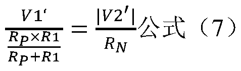
[0070] 控制器 1再联立上述公式 (6) 与公式 (7) 得到方程组, 代入检测电阻 R1 的阻值, 以及采集的 VI、 V2、 VI \ V2‘的值, 可以求出绝缘电阻 RP与绝缘电阻 RN W阻值。
[0071] (2)控制器 1在 Vl <| V2|时, 选取电池组 2的负极作为目标电极, 闭合连接于电池 组 2的负极的检测回路 3的检测开关 S5, 再次采集电池组 2的正极对参考电位端 G的电压 V1 ‘‘、 电池组 2的负极对参考电位端 G的电压 V2‘‘, 可以得到:

[0072] 控制器 1再联立上述公式 (6) 与公式 (8) 得到方程组, 代入检测电阻 R3的阻值, 以及采集的 VI、 V2、 V1 ‘‘、 V2‘‘的值, 可以求出绝缘电阻 RP与绝缘电阻 RN W阻值。
[0073] 在一个例子中, 本实施例在控制器 1检测绝缘电阻 RP与绝缘电阻 RN的阻值之后, 根 据绝缘电阻 RP与绝缘电阻 RN m阻值, 判断是否出现绝缘故障, 例如阻值过低的短路故障, 阻值过高的不安全故障等; 当绝缘电阻 RP与绝缘电阻 RN m阻值均在预设的范围内时, 判定 未出现绝缘故障,再检测主正开关模块 S 1与主负开关模块 S2的外侧的绝缘电阻 RP_EX与 RN_EX 的阻值, 提升了安全性, 绝缘电阻 RP-EX与 RN-EX W阻值的检测方式不再赘述。
[0074] 本实施例相对于第一实施例而言, 当主正开关模块的内侧和 /或主负开关模块的内侧 通过至少一检测回路连接到参考电位端, 还能够检测主正开关模块与主负开关模块的内侧的 绝缘电阻。 需要说明的是, 本实施例还可以作为在第二实施例或第三实施例基础上的改进, 可以达到同样的技术效果。
[0075] 本申请的第五实施例涉及一种检测方法, 应用于第一实施例中的检测电路, 请参考图
1至图 4, 下面以图 4的检测电路为例进行说明。
[0076] 本实施例的检测方法具体流程如图 10所示。
[0077] 步骤 101, 在检测电路处于初始状态时, 闭合主正开关模块或主负开关模块, 采集电 池组的正极与负极的电压以及主正开关模块的外侧与主负开关模块的外侧之间的电压。
[0078] 具体而言, 当主正开关模块 S 1、 主负开关模块 S2以及检测开关 S3均处于断开状态 时, 检测电路处于初始状态, 控制器 1闭合主正开关模块 S 1或主负开关模块 S2, 采集电池 组 2的正极对参考电位端 G的电压 VI、电池组 2的负极对参考电位端 G的电压 V2以及主正 开关模块 S 1的外侧与主负开关模块 S2的外侧之间的电压 V3 ;以闭合主负开关模块 S2为例, 此时, 采集电压 VI、 V2、 V3, 基于基尔霍夫电流定理, 可以得到:

[0079] 步骤 102, 闭合任一检测回路, 再次采集电池组的正极与负极的电压以及主正开关模 块的外侧与主负开关模块的外侧之间的电压。
[0080] 具体而言, 控制器 1闭合检测开关 S3, 再次采集电池组 2的正极对参考电位端 G的 电压 VI ‘、 电池组 2的负极对参考电位端 G的电压 V2‘以及主正开关模块 S1的外侧与主负 开关模块 S2的外侧之间的电压 V3‘, 以闭合主负开关模块 S2为例, 此时, 采集电压 V1 ‘、 V2‘、 V3‘, 基于基尔霍夫电流定理, 可以得到:

[0081] 步骤 103 , 根据主正开关模块与主负开关模块的内侧的绝缘电阻, 以及两次采集的电 池组的正极与负极的电压以及主正开关模块的外侧与主负开关模块的外侧之间的电压, 得到 主正开关模块与主负开关模块的外侧的绝缘电阻。
[0082] 具体而言, 控制器 1 再联立上述公式 (1) 与公式 (2) 得到方程组, 代入绝缘电阻 RP、 绝缘电阻 Rn、检测电阻 R1 的阻值, 以及采集的 VI、 V2、 V3、 VI \ V2 V3‘的值, 可以求出绝缘电阻 Rp_EX与绝缘电阻 Rw_EX的阻值。
[0083] 由于第一实施例与本实施例相互对应, 因此本实施例可与第一实施例互相配合实施。 第一实施例中提到的相关技术细节在本实施例中依然有效, 在第一实施例中所能达到的技术 效果在本实施例中也同样可以实现, 为了减少重复, 这里不再赘述。 相应地, 本实施例中提 到的相关技术细节也可应用在第一实施例中。
[0084] 本实施例相对于现有技术而言, 在检测电路中的主正开关模块、主负开关模块以及各 检测回路均处于断开状态时, 闭合主正开关模块或主负开关模块, 采集电池组正极的电压、
电池组负极的电压, 以及主正开关模块的外侧与主负开关模块的外侧之间的电压; 然后, 闭 合任一检测电路, 再次采集电池组正极的电压、 电池组负极的电压, 以及主正开关模块的外 侧与主负开关模块的外侧之间的电压, 继而根据主正开关模块与主负开关模块内侧的绝缘电 阻、 两次采集的电池组正极的电压、 电池组负极的电压, 以及主正开关模块的外侧与主负开 关模块的外侧之间的电压, 得到主正开关模块与主负开关模块的外侧的绝缘电阻; 即, 能够 检测主正开关模块的外侧对参考电位端的绝缘电阻与主负开关模块外侧对参考电位端的绝缘 电阻, 以获取主正开关模块与主负开关模块外侧的绝缘性能, 避免出现危险接触。
[0085] 本申请的第六实施例涉及一种检测方法, 第六实施例与第五实施例大致相同, 主要区 别之处在于: 通过闭合预充模块实现绝缘电阻 RP-EX与 RN-EX的阻值的检测, 本实施例中, 以 图 6的检测电路为例进行说明。
[0086] 本实施例的检测方法具体流程如图 11所示。
[0087] 步骤 201, 在检测电路处于初始状态时, 闭合主正开关模块、 主负开关模块以及预充 模块中的任意之一, 采集电池组的正极与负极的电压以及主正开关模块的外侧与主负开关模 块的外侧之间的电压。
[0088] 具体而言, 当主正开关模块 S 1、 主负开关模块 S2、 检测开关 S3以及预充接触器 S4 均处于断开状态时, 检测电路处于初始状态, 控制器 1闭合主正开关模块 S 1、 主负开关模块 S2以及预充接触器 S4中的任意之一,采集电池组 2的正极对参考电位端 G的电压 VI、 电池 组 2的负极对参考电位端 G的电压 V2以及主正开关模块 S 1的外侧与主负开关模块 S2的外 侧之间的电压 V3 ; 以闭合预充接触器 S4为例, 此时, 采集电压 VI、 V2、 V3, 基于基尔霍 夫电流定理, 可以得到:

[0089] 步骤 202, 闭合任一检测回路, 再次采集电池组的正极与负极的电压以及主正开关模 块的外侧与主负开关模块的外侧之间的电压。
[0090] 具体而言, 控制器 1闭合检测开关 S3, 再次采集电池组 2的正极对参考电位端 G的 电压 VI ‘、 电池组 2的负极对参考电位端 G的电压 V2‘以及主正开关模块 S1的外侧与主负 开关模块 S2的外侧之间的电压 V3‘, 以闭合预充接触器 S4为例, 此时, 采集电压 VI ‘、
V2‘、 V3‘, 基于基尔霍夫电流定理, 可以得到:

[0091] 步骤 203 , 根据主正开关模块与主负开关模块的内侧的绝缘电阻, 以及两次采集的电
池组的正极与负极的电压以及主正开关模块的外侧与主负开关模块的外侧之间的电压, 得到 主正开关模块与主负开关模块的外侧的绝缘电阻。
[0092] 具体而言, 控制器 1 再联立上述公式 (1) 与公式 (2) 得到方程组, 代入绝缘电阻 RP、 绝缘电阻 RN、 检测电阻 R1、 预充电阻 R2的阻值, 以及采集的 VI、 V2、 V3、 VI \ V2 ‘、 V3‘的值, 可以求出绝缘电阻 RP-EX与绝缘电阻 RN-EX的阻值。
[0093] 由于第二实施例与本实施例相互对应, 因此本实施例可与第二实施例互相配合实施。 第二实施例中提到的相关技术细节在本实施例中依然有效, 在第二实施例中所能达到的技术 效果在本实施例中也同样可以实现, 为了减少重复, 这里不再赘述。 相应地, 本实施例中提 到的相关技术细节也可应用在第二实施例中。
[0094] 本实施例相对于第五实施例而言, 若检测电路中包括预充模块, 闭合预充模块同样能 够检测主正开关模块与主负开关模块外侧的绝缘电阻。
[0095] 本申请的第七实施例涉及一种检测方法, 本实施例与第五实施例的大致相同, 主要区 别之处在于: 提升了电压采集的精准度, 本实施例中, 以图 7的检测电路为例进行说明。
[0096] 本实施例的检测方法具体流程如图 12所示。
[0097] 步骤 301, 在检测电路处于初始状态时, 闭合主正开关模块或主负开关模块, 采集电 池组的正极与负极的电压以及主正开关模块的外侧与主负开关模块的外侧之间的电压。
[0098] 具体而言, 当主正开关模块 S 1、 主负开关模块 S2以及检测开关 S3均处于断开状态 时, 检测电路处于初始状态, 控制器 1闭合主正开关模块 S 1或主负开关模块 S2, 采集电池 组 2的正极对参考电位端 G的电压 VI、电池组 2的负极对参考电位端 G的电压 V2以及主正 开关模块 S 1的外侧与主负开关模块 S2的外侧之间的电压 V3 ;以闭合主负开关模块 S2为例, 此时, 采集电压 VI、 V2、 V3, 基于基尔霍夫电流定理, 可以得到:

[0099] 步骤 302, 选取电池组的正极与负极中电压大的电极, 记作目标电极。
[00100]步骤 303 , 闭合连接于目标电极的检测回路, 再次采集电池组的正极与负极的电压以 及主正开关模块的外侧与主负开关模块的外侧之间的电压。
[00101]步骤 304, 根据主正开关模块与主负开关模块的内侧的绝缘电阻, 以及两次采集的电 池组的正极与负极的电压以及主正开关模块的外侧与主负开关模块的外侧之间的电压, 得到 主正开关模块与主负开关模块的外侧的绝缘电阻。
[00102]具体而言, 控制器 1判断电池组 2的正极对参考电位端 G的电压 VI、 电池组 2的正 极对参考电位端 G的电压 V2之间的大小关系, 其中当 V2为负值时, 取绝对值; 可以分为
以下两种情况, 具体如下:
[00103] (1)控制器 1在 Vl >| V2|时, 选取电池组 2的正极作为目标电极, 闭合连接于电池 组 2的正极的检测回路 3的检测开关 S3 , 再次采集电池组 2的正极对参考电位端 G的电压 VI \电池组 2的负极对参考电位端 G的电压 V2‘以及主正开关模块 S 1的外侧与主负开关模 块 S2的外侧之间的电压 V3‘, 以闭合主负开关模块 S2为例, 此时, 采集电压 VI ‘、 V2‘、 V3‘, 基于基尔霍夫电流定理, 可以得到: 2:公式 (4)

[00104]控制器 1再联立上述公式 (3) 与公式 (4) 得到方程组, 代入绝缘电阻 RP、 绝缘电 阻 RN、 检测电阻 R1的阻值, 以及采集的 VI、 V2、 V3、 VI \ V2‘、 V3‘的值, 可以求出绝 缘电阻 Rp_EX与绝缘电阻 Rw_EX的阻值。
[00105] (2)控制器 1在 Vl <| V2|时, 选取电池组 2的负极作为目标电极, 闭合连接于电池 组 2的负极的检测回路 3的检测开关 S5, 再次采集电池组 2的正极对参考电位端 G的电压 V1 ‘‘、 电池组 2的负极对参考电位端 G的电压 V2‘‘以及主正开关模块 S 1的外侧与主负开关 模块 S2的外侧之间的电压 V3‘‘, 以闭合主负开关模块 S2为例,此时,采集电压 VI‘‘、 V2‘‘、 V3‘‘, 基于基尔霍夫电流定理, 可以得到:

[00106]控制器 1再联立上述公式 (3) 与公式 (5) 得到方程组, 代入绝缘电阻 RP、 绝缘电 阻 RN、 检测电阻 R3的阻值, 以及采集的 VI、 V2、 V3、 V1 ‘‘、 V2‘‘、 V3‘‘的值, 可以求出
 的阻值。
的阻值。
[00107]需要说明的是, 本实施例中也可以设置主正开关模块 S 1 的外侧与主负开关模块 S2 的外侧均通过至少一检测回路 3连接到参考电位端 G, 如图 8所示, 同样能够检测绝缘电阻 RP_EX与绝缘电阻 RN_EX的阻值, 具体与上述方式类似, 在此不再赘述。
[00108]还需要说明的是,主正开关模块 S 1的内侧与主负开关模块 S2的内侧均通过多个检测 回路 3连接到参考电位端 G, 如图 9所示, 以主正开关模块 S 1的内侧与主负开关模块 S2的 内侧通过并联的两个检测回路 3连接到参考电位端 G为例, 同样能够检测绝缘电阻 RP-EX与 绝缘电阻 RW_EX的阻值。
[00109] 由于第三实施例与本实施例相互对应, 因此本实施例可与第三实施例互相配合实施。 第三实施例中提到的相关技术细节在本实施例中依然有效, 在第三实施例中所能达到的技术 效果在本实施例中也同样可以实现, 为了减少重复, 这里不再赘述。 相应地, 本实施例中提
到的相关技术细节也可应用在第三实施例中。
[00110]本实施例相对于第五实施例而言, 闭合连接于电压较大的电极的检测回路, 从而能够 减小电池组两个电极之间的电压, 提升了电压采集的精准度。 需要说明的是, 本实施例还可 以作为在第六实施例基础上的改进, 可以达到同样的技术效果。
[00111]本申请的第八实施例涉及一种检测方法, 本实施例与第五实施例的大致相同, 主要区 别之处在于: 能够检测主正开关模块 S 1与主负开关模块 S2的内侧的绝缘电阻的阻值, 本实 施例以图 7的检测电路为例进行说明。
[00112]本实施例的检测方法具体流程如图 13所示。
[00113]其中, 步骤 403至步骤 405与步骤 101至步骤 103大致相同, 在此不再赘述, 主要不 同之处在于:
[00114]步骤 401, 在检测电路处于初始状态时, 采集电池组的正极与负极的电压, 在闭合任 一检测回路后, 再次采集电池组的正极与负极的电压, 并根据两次采集的电池组的正极与负 极的电压得到主正开关模块与主负开关模块的内侧的绝缘电阻, 包括以下子步骤:
[00115]子步骤 4011, 在检测电路处于初始状态时, 采集电池组的正极与负极的电压, 并选 取电池组的正极与负极中电压大的电极, 记作目标电极。
[00116]子步骤 4012, 闭合连接于目标电极的检测回路, 再次采集电池组的正极与负极的电 压, 并根据两次采集的电池组的正极与负极的电压得到主正开关模块与主负开关模块的内侧 的绝缘电阻。
[00117]具体而言, 当主正开关模块 S 1、 主负开关模块 S2以及检测开关 S3均处于断开状态 时, 检测电路处于初始状态, 控制器 1采集电池组 2的正极对参考电位端 G的电压 VI、 电 池组 2的负极对参考电位端 G的电压 V2, 可以得到:

[00118]控制器 1再判断电池组 2的正极对参考电位端 G的电压 VI、 电池组 2的正极对参考 电位端 G的电压 V2之间的大小关系, 其中当 V2为负值时, 取绝对值; 可以分为以下两种 情况, 具体如下:
[00119] (1)控制器 1在 Vl >| V2|时, 选取电池组 2的正极作为目标电极, 闭合连接于电池 组 2的正极的检测回路 3的检测开关 S3 , 再次采集电池组 2的正极对参考电位端 G的电压 VI \ 电池组 2的负极对参考电位端 G的电压 V2‘, 可以得到:

[00120]控制器 1再联立上述公式 (6) 与公式 (7) 得到方程组, 代入检测电阻 R1 的阻值,
以及采集的 VI、 V2、 VI \ V2‘的值, 可以求出绝缘电阻 RP与绝缘电阻 RN W阻值。
[00121] (2)控制器 1在 Vl <| V2|时, 选取电池组 2的负极作为目标电极, 闭合连接于电池 组 2的负极的检测回路 3的检测开关 S5, 再次采集电池组 2的正极对参考电位端 G的电压 V1 ‘‘、 电池组 2的负极对参考电位端 G的电压 V2‘‘, 可以得到: f = M公式 ⑻
Rf\j+R3
[00122]控制器 1再联立上述公式 (6) 与公式 (8) 得到方程组, 代入检测电阻 R3的阻值, 以及采集的 VI、 V2、 V1 ‘‘、 V2‘‘的值, 可以求出绝缘电阻 RP与绝缘电阻 RN W阻值。
[00123]步骤 402, 根据主正开关模块与主负开关模块的内侧的绝缘电阻, 判断是否出现绝缘 故障。 若是, 则直接结束; 若否, 则进入步骤 403。
[00124]具体而言, 根据绝缘电阻 RP与绝缘电阻 1^的阻值, 判断是否出现绝缘故障, 例如阻 值过低的短路故障, 阻值过高的不安全故障等; 当绝缘电阻 RP与绝缘电阻 RN的阻值均在预 设的范围内时, 判定未出现绝缘故障, 控制检测电路处于初始状态, 即断开已闭合的主正开 关模块 S 1或主负开关模块 S2,再进入步骤 403 ,进行绝缘电阻 RP-EX与 RN-EX的阻值的检测, 提升了安全性; 控制器在判定出现绝缘故障后, 向整车的控制系统上报故障。 另外, 在完成 主正开关模块 S 1与主负开关模块 S2的外侧的绝缘电阻 RP_EX与 RN_EX的检测后,也可以根据 绝缘电阻 RP-EX与 RN-EX W阻值, 判断是否出现绝缘故障, 在判定未出现绝缘故障后, 再闭合 主正开关模块 S 1与主负开关模块 S2; 反之, 则向整车的控制系统上报故障。
[00125] 由于第四实施例与本实施例相互对应, 因此本实施例可与第四实施例互相配合实施。 第四实施例中提到的相关技术细节在本实施例中依然有效, 在第四实施例中所能达到的技术 效果在本实施例中也同样可以实现, 为了减少重复, 这里不再赘述。 相应地, 本实施例中提 到的相关技术细节也可应用在第四实施例中。
[00126]本实施例相对于第五实施例而言, 当主正开关模块的内侧和 /或主负开关模块的内侧 通过至少一检测回路连接到参考电位端, 还能够检测主正开关模块与主负开关模块的内侧的 绝缘电阻。 需要说明的是, 本实施例还可以作为在第六实施例或第七实施例基础上的改进, 可以达到同样的技术效果。
[00127]本领域的普通技术人员可以理解, 上述各实施例是实现本申请的具体实施例, 而在实 际应用中, 可以在形式上和细节上对其作各种改变, 而不偏离本申请的精神和范围。
Claims
1. 一种检测电路, 包括: 控制器、 电池组、 主正开关模块、 主负开关模块以及至少一检 测回路;
所述主正开关模块的两侧与所述主负开关模块的两侧均连接于参考电位端, 且所述主正 开关模块的一侧和 /或所述主负开关模块的一侧通过至少一所述检测回路连接到所述参考电 位端; 所述电池组的正极连接于所述主正开关模块的内侧, 所述电池组的负极连接于所述主 负开关模块的内侧;
所述控制器用于在所述检测电路处于初始状态时, 闭合所述主正开关模块或所述主负开 关模块, 采集所述电池组的正极与负极的电压以及所述主正开关模块的外侧与所述主负开关 模块的外侧之间的电压, 在闭合任一所述检测回路后, 再次采集所述电池组的正极与负极的 电压以及所述主正开关模块的外侧与所述主负开关模块的外侧之间的电压, 其中, 所述初始 状态为所述主正开关模块、 所述主负开关模块以及各所述检测回路均处于断开状态;
所述控制器还用于根据所述主正开关模块与所述主负开关模块的内侧的绝缘电阻, 以及 两次采集的所述电池组的正极与负极的电压以及所述主正开关模块的外侧与所述主负开关模 块的外侧之间的电压, 得到所述主正开关模块与所述主负开关模块的外侧的绝缘电阻。
2. 根据权利要求 1所述的检测电路, 其中, 所述检测电路还包括: 预充模块, 所述预充 模块与所述主正开关模块或所述主负开关模块并联;
所述控制器具体用于在所述检测电路处于初始状态时, 闭合所述主正开关模块、 所述主 负开关模块以及所述预充模块中的任意之一, 采集所述电池组的正极与负极的电压以及所述 主正开关模块的外侧与所述主负开关模块的外侧之间的电压, 在闭合任一所述检测回路后, 再次采集所述电池组的正极与负极的电压以及所述主正开关模块的外侧与所述主负开关模块 的外侧之间的电压。
3. 根据权利要求 1所述的检测电路, 其中, 所述主正开关模块的内侧与所述主负开关模 块的内侧均通过至少一所述检测回路连接到所述参考电位端; 所述控制器用于在所述检测电 路处于初始状态时, 闭合所述主正开关模块或所述主负开关模块, 采集所述电池组的正极与 负极的电压以及所述主正开关模块的外侧与所述主负开关模块的外侧之间的电压, 并选取所 述电池组的正极与负极中电压大的电极, 记作目标电极;
所述控制器用于在闭合连接于所述目标电极的所述检测回路后, 再次采集所述电池组的 正极与负极的电压以及所述主正开关模块的外侧与所述主负开关模块的外侧之间的电压。
4. 根据权利要求 1 所述的检测电路, 其中, 所述主正开关模块的内侧和 /或所述主负开 关模块的内侧通过至少一所述检测回路连接到所述参考电位端;
所述控制器还用于在所述检测电路处于初始状态时, 采集所述电池组的正极与负极的电 压, 在闭合任一所述检测回路后, 再次采集所述电池组的正极与负极的电压, 并根据两次采 集的所述电池组的正极与负极的电压得到所述主正开关模块与所述主负开关模块的内侧的绝 缘电阻。
5. 根据权利要求 4所述的检测电路, 其中, 所述控制器还用于根据所述主正开关模块与 所述主负开关模块的内侧的绝缘电阻, 判断是否出现绝缘故障;
所述控制器用于在判定未出现绝缘故障时, 控制所述检测电路处于初始状态, 并闭合所 述主正开关模块或所述主负开关模块, 采集所述电池组的正极与负极的电压以及所述主正开 关模块的外侧与所述主负开关模块的外侧之间的电压, 在闭合任一所述检测回路后, 再次采 集所述电池组的正极与负极的电压以及所述主正开关模块的外侧与所述主负开关模块的外侧 之间的电压。
6. 根据权利要求 4所述的检测电路, 其中, 所述主正开关模块的内侧和所述主负开关模 块的内侧均通过至少一所述检测回路连接到所述参考电位端; 所述控制器用于在所述检测电 路处于初始状态时, 采集所述电池组的正极与负极的电压, 并选取所述电池组的正极与负极 中电压大的电极, 记作目标电极;
所述控制器用于在闭合连接于所述目标电极的所述检测回路后, 再次采集所述电池组的 正极与负极的电压, 并根据两次采集的所述电池组的正极与负极的电压得到所述主正开关模 块与所述主负开关模块的内侧的绝缘电阻。
7. 根据权利要求 1所述的检测电路, 其中, 所述检测回路包括检测开关与检测电阻。
8. 根据权利要求 2所述的检测电路, 其中, 所述预充模块包括预充接触器与预充电阻。
9. 一种检测方法, 应用于权利要求 1所述的检测电路; 所述方法包括:
在所述检测电路处于初始状态时, 闭合主正开关模块或主负开关模块, 采集电池组的正 极与负极的电压以及所述主正开关模块的外侧与所述主负开关模块的外侧之间的电压,其中, 所述初始状态为所述主正开关模块、所述主负开关模块以及各所述检测回路均处于断开状态; 闭合任一所述检测回路, 再次采集所述电池组的正极与负极的电压以及所述主正开关模 块的外侧与所述主负开关模块的外侧之间的电压;
根据所述主正开关模块与所述主负开关模块的内侧的绝缘电阻, 以及两次采集的所述电 池组的正极与负极的电压以及所述主正开关模块的外侧与所述主负开关模块的外侧之间的电
压, 得到所述主正开关模块与所述主负开关模块的外侧的绝缘电阻。
10. 根据权利要求 9所述的检测方法, 其中, 所述检测电路还包括: 预充模块, 所述预 充模块与所述主正开关模块或所述主负开关模块并联;
所述在所述检测电路处于初始状态时, 闭合主正开关模块或主负开关模块, 采集电池组 的正极与负极的电压以及所述主正开关模块的外侧与所述主负开关模块的外侧之间的电压, 具体为:
在所述检测电路处于初始状态时, 闭合所述主正开关模块、 所述主负开关模块以及所述 预充模块中的任意之一, 采集所述电池组的正极与负极的电压以及所述主正开关模块的外侧 与所述主负开关模块的外侧之间的电压。
11. 根据权利要求 9所述的检测方法, 其中, 所述主正开关模块的内侧与所述主负开关 模块的内侧均通过至少一所述检测回路连接到参考电位端;
在所述闭合任一所述检测回路, 再次采集所述电池组的正极与负极的电压以及所述主正 开关模块的外侧与所述主负开关模块的外侧之间的电压之前, 还包括:
选取所述电池组的正极与负极中电压大的电极, 记作目标电极;
所述闭合任一所述检测回路, 再次采集所述电池组的正极与负极的电压以及所述主正开 关模块的外侧与所述主负开关模块的外侧之间的电压, 具体为:
闭合连接于所述目标电极的所述检测回路, 再次采集所述电池组的正极与负极的电压以 及所述主正开关模块的外侧与所述主负开关模块的外侧之间的电压。
12. 根据权利要求 9所述的检测方法, 其中, 所述主正开关模块的内侧和 /或所述主负开 关模块的内侧通过至少一所述检测回路连接到参考电位端;
所述在所述检测电路处于初始状态时, 闭合主正开关模块或主负开关模块, 采集电池组 的正极与负极的电压以及所述主正开关模块的外侧与所述主负开关模块的外侧之间的电压之 前, 还包括:
在所述检测电路处于初始状态时, 采集所述电池组的正极与负极的电压, 在闭合任一所 述检测回路后, 再次采集所述电池组的正极与负极的电压, 并根据两次采集的所述电池组的 正极与负极的电压得到所述主正开关模块与所述主负开关模块的内侧的绝缘电阻。
13. 根据权利要求 12所述的检测方法, 其中, 所述在所述检测电路处于初始状态时, 闭 合主正开关模块或主负开关模块, 采集电池组的正极与负极的电压以及所述主正开关模块的 外侧与所述主负开关模块的外侧之间的电压之前, 还包括:
根据所述主正开关模块与所述主负开关模块的内侧的绝缘电阻,判断是否出现绝缘故障;
若判定未出现绝缘故障, 控制所述检测电路处于初始状态, 并进入所述在所述检测电路 处于初始状态时, 闭合主正开关模块或主负开关模块, 采集电池组的正极与负极的电压以及 所述主正开关模块的外侧与所述主负开关模块的外侧之间的电压的步骤。
14. 根据权利要求 12所述的检测方法, 其中, 所述主正开关模块的内侧和所述主负开关 模块的内侧均通过至少一所述检测回路连接到参考电位端;
所述在所述检测电路处于初始状态时, 采集所述电池组的正极与负极的电压, 在闭合任 一所述检测回路后, 再次采集所述电池组的正极与负极的电压, 并根据两次采集的所述电池 组的正极与负极的电压得到所述主正开关模块与所述主负开关模块的内侧的绝缘电阻,包括: 在所述检测电路处于初始状态时, 采集所述电池组的正极与负极的电压, 并选取所述电 池组的正极与负极中电压大的电极, 记作目标电极;
闭合连接于所述目标电极的所述检测回路, 再次采集所述电池组的正极与负极的电压, 并根据两次采集的所述电池组的正极与负极的电压得到所述主正开关模块与所述主负开关模 块的内侧的绝缘电阻。
Applications Claiming Priority (2)
| Application Number | Priority Date | Filing Date | Title |
|---|---|---|---|
| CN201910138988.0 | 2019-02-25 | ||
| CN201910138988.0A CN110967557B (zh) | 2019-02-25 | 2019-02-25 | 检测电路及方法 |
Publications (1)
| Publication Number | Publication Date |
|---|---|
| WO2020173429A1 true WO2020173429A1 (zh) | 2020-09-03 |
Family
ID=69742656
Family Applications (1)
| Application Number | Title | Priority Date | Filing Date |
|---|---|---|---|
| PCT/CN2020/076601 Ceased WO2020173429A1 (zh) | 2019-02-25 | 2020-02-25 | 检测电路及方法 |
Country Status (4)
| Country | Link |
|---|---|
| US (1) | US11258278B2 (zh) |
| EP (1) | EP3699616B1 (zh) |
| CN (1) | CN110967557B (zh) |
| WO (1) | WO2020173429A1 (zh) |
Families Citing this family (6)
| Publication number | Priority date | Publication date | Assignee | Title |
|---|---|---|---|---|
| CN110967557B (zh) * | 2019-02-25 | 2021-06-15 | 宁德时代新能源科技股份有限公司 | 检测电路及方法 |
| CA3174967A1 (en) * | 2020-04-21 | 2021-10-28 | Alex S. Creviston | Adaptable precharge |
| CN113835039B (zh) * | 2020-06-23 | 2023-01-20 | 株洲中车时代电气股份有限公司 | 一种接地检测电路及方法 |
| CN112578300A (zh) * | 2020-11-30 | 2021-03-30 | 珠海格力电器股份有限公司 | 一种动力电池的绝缘电阻的检测装置、方法和汽车 |
| CN116893360B (zh) * | 2023-06-06 | 2025-11-28 | 惠州亿纬锂能股份有限公司 | 电池绝缘的虚压检测电路、虚压检测方法及电子设备 |
| CN118358360B (zh) * | 2024-04-18 | 2026-02-10 | 比亚迪股份有限公司 | 一种双重检测电路、电池系统及车辆 |
Citations (9)
| Publication number | Priority date | Publication date | Assignee | Title |
|---|---|---|---|---|
| US20070285102A1 (en) * | 2006-05-16 | 2007-12-13 | Sma Technologie Ag | Measuring array |
| CN104020421A (zh) * | 2014-06-06 | 2014-09-03 | 浙江工商职业技术学院 | 一种多点的电动汽车绝缘测试系统及检测方法 |
| KR20150084532A (ko) * | 2014-01-14 | 2015-07-22 | 주식회사 엘지화학 | 절연 저항 측정 장치 및 방법 |
| US20160154064A1 (en) * | 2014-11-27 | 2016-06-02 | Hella Kgaa Hueck & Co. | Switching status check with circuit parts of an insulation monitor |
| CN207181530U (zh) * | 2017-08-24 | 2018-04-03 | 上海科海华泰船舶电气有限公司 | 船用绝缘监测直流电网对地绝缘电阻测量电路 |
| WO2018139830A1 (ko) * | 2017-01-24 | 2018-08-02 | 주식회사 엘지화학 | 음극 릴레이를 이용한 배터리팩의 절연저항 측정 장치 및 측정 방법 |
| CN208239523U (zh) * | 2018-04-25 | 2018-12-14 | 吉利汽车研究院(宁波)有限公司 | 一种绝缘电阻检测电路 |
| CN109100618A (zh) * | 2017-06-20 | 2018-12-28 | 联合汽车电子有限公司 | 高压电池绝缘检测系统及方法 |
| CN109212385A (zh) * | 2017-06-29 | 2019-01-15 | 宝沃汽车(中国)有限公司 | 电动汽车的整车电路绝缘检测方法和装置 |
Family Cites Families (12)
| Publication number | Priority date | Publication date | Assignee | Title |
|---|---|---|---|---|
| JP5613408B2 (ja) | 2009-10-13 | 2014-10-22 | 矢崎総業株式会社 | 絶縁計測装置 |
| EP2570289B1 (de) | 2011-09-16 | 2018-08-15 | Samsung SDI Co., Ltd. | Einrichtung zur Erfassung des Isolationswiderstandes eines Hochvoltbatteriesystems |
| KR101908637B1 (ko) | 2012-01-05 | 2018-10-17 | 에스케이이노베이션 주식회사 | 절연 저항 측정 회로 |
| US9046559B2 (en) | 2012-05-09 | 2015-06-02 | Curtis Instruments, Inc. | Isolation monitor |
| CN103869179B (zh) | 2012-12-14 | 2016-12-21 | 比亚迪股份有限公司 | 一种直流系统的绝缘监测方法 |
| JP6401599B2 (ja) * | 2014-12-18 | 2018-10-10 | カルソニックカンセイ株式会社 | 車両用地絡検出装置 |
| JP6697869B2 (ja) * | 2015-12-02 | 2020-05-27 | 株式会社デンソーテン | 状態判定装置および状態判定方法 |
| JP6706688B2 (ja) * | 2016-11-30 | 2020-06-10 | 日立オートモティブシステムズ株式会社 | 電池制御装置 |
| CN106908719A (zh) | 2017-02-13 | 2017-06-30 | 上海蔚来汽车有限公司 | 车辆直流充电继电器的诊断系统 |
| JP6794889B2 (ja) * | 2017-03-21 | 2020-12-02 | 株式会社デンソー | 電圧検出装置 |
| US20210141023A1 (en) * | 2018-07-31 | 2021-05-13 | Nidec-Read Corporation | Battery impedance measuring device |
| CN110967557B (zh) * | 2019-02-25 | 2021-06-15 | 宁德时代新能源科技股份有限公司 | 检测电路及方法 |
-
2019
- 2019-02-25 CN CN201910138988.0A patent/CN110967557B/zh active Active
-
2020
- 2020-02-24 US US16/799,729 patent/US11258278B2/en active Active
- 2020-02-25 WO PCT/CN2020/076601 patent/WO2020173429A1/zh not_active Ceased
- 2020-02-25 EP EP20159222.7A patent/EP3699616B1/en active Active
Patent Citations (9)
| Publication number | Priority date | Publication date | Assignee | Title |
|---|---|---|---|---|
| US20070285102A1 (en) * | 2006-05-16 | 2007-12-13 | Sma Technologie Ag | Measuring array |
| KR20150084532A (ko) * | 2014-01-14 | 2015-07-22 | 주식회사 엘지화학 | 절연 저항 측정 장치 및 방법 |
| CN104020421A (zh) * | 2014-06-06 | 2014-09-03 | 浙江工商职业技术学院 | 一种多点的电动汽车绝缘测试系统及检测方法 |
| US20160154064A1 (en) * | 2014-11-27 | 2016-06-02 | Hella Kgaa Hueck & Co. | Switching status check with circuit parts of an insulation monitor |
| WO2018139830A1 (ko) * | 2017-01-24 | 2018-08-02 | 주식회사 엘지화학 | 음극 릴레이를 이용한 배터리팩의 절연저항 측정 장치 및 측정 방법 |
| CN109100618A (zh) * | 2017-06-20 | 2018-12-28 | 联合汽车电子有限公司 | 高压电池绝缘检测系统及方法 |
| CN109212385A (zh) * | 2017-06-29 | 2019-01-15 | 宝沃汽车(中国)有限公司 | 电动汽车的整车电路绝缘检测方法和装置 |
| CN207181530U (zh) * | 2017-08-24 | 2018-04-03 | 上海科海华泰船舶电气有限公司 | 船用绝缘监测直流电网对地绝缘电阻测量电路 |
| CN208239523U (zh) * | 2018-04-25 | 2018-12-14 | 吉利汽车研究院(宁波)有限公司 | 一种绝缘电阻检测电路 |
Also Published As
| Publication number | Publication date |
|---|---|
| CN110967557B (zh) | 2021-06-15 |
| US11258278B2 (en) | 2022-02-22 |
| EP3699616B1 (en) | 2021-06-23 |
| CN110967557A (zh) | 2020-04-07 |
| EP3699616A1 (en) | 2020-08-26 |
| US20200274374A1 (en) | 2020-08-27 |
Similar Documents
| Publication | Publication Date | Title |
|---|---|---|
| CN110967557B (zh) | 检测电路及方法 | |
| CN110873845A (zh) | 一种绝缘检测方法 | |
| CN107991625B (zh) | 动力蓄电池系统绝缘电阻检测电路与检测方法 | |
| CN110398633B (zh) | 一种电动汽车的绝缘阻抗检测方法 | |
| CN106291112A (zh) | 绝缘电阻检测电路及方法 | |
| CN102841284B (zh) | 一种电动汽车高压电在线绝缘监测方法 | |
| CN112578300A (zh) | 一种动力电池的绝缘电阻的检测装置、方法和汽车 | |
| CN110967606A (zh) | 绝缘检测电路及检测方法、电池管理系统 | |
| CN103278776B (zh) | 一种电动汽车电池绝缘检测系统 | |
| CN102156252B (zh) | 一种电动汽车用绝缘检测装置 | |
| CN207780205U (zh) | 一种高压直流电源对地绝缘阻抗检测电路 | |
| CN107478908B (zh) | 一种电动车绝缘检测装置及其检测方法 | |
| CN109917240B (zh) | 一种双边直流绝缘检测方法和系统 | |
| CN110568366A (zh) | 一种绝缘电路、电池组漏电检测方法及硬件检测方法 | |
| CN105527535A (zh) | 基于可变电阻网络的直流漏电绝缘检测系统及方法 | |
| WO2018145397A1 (zh) | 车辆直流充电继电器的诊断系统 | |
| CN113125974B (zh) | 一种电池析锂检测方法及装置 | |
| CN116338309A (zh) | 绝缘电阻检测装置 | |
| CN106932645A (zh) | 基于直流it系统的绝缘电阻检测电路及检测方法 | |
| CN111873820A (zh) | 高压检测电路、电流采样单元、检测器、电池装置、运载工具与供电装置 | |
| CN114938661B (zh) | 电池系统的检测方法和装置 | |
| WO2020177575A1 (zh) | 一种绝缘阻值的检测方法、装置、电子设备及存储介质 | |
| CN108872812B (zh) | 一种低成本绝缘漏电检测电路及检测方法 | |
| CN213813839U (zh) | 一种电池系统绝缘检测电路和电池系统 | |
| CN114252712A (zh) | 电池包绝缘检测电路、方法和车辆 |
Legal Events
| Date | Code | Title | Description |
|---|---|---|---|
| 121 | Ep: the epo has been informed by wipo that ep was designated in this application |
Ref document number: 20762720 Country of ref document: EP Kind code of ref document: A1 |
|
| NENP | Non-entry into the national phase |
Ref country code: DE |
|
| 122 | Ep: pct application non-entry in european phase |
Ref document number: 20762720 Country of ref document: EP Kind code of ref document: A1 |