WO2020173077A1 - 一种带新型箱体的燃料电池 - Google Patents
一种带新型箱体的燃料电池 Download PDFInfo
- Publication number
- WO2020173077A1 WO2020173077A1 PCT/CN2019/105377 CN2019105377W WO2020173077A1 WO 2020173077 A1 WO2020173077 A1 WO 2020173077A1 CN 2019105377 W CN2019105377 W CN 2019105377W WO 2020173077 A1 WO2020173077 A1 WO 2020173077A1
- Authority
- WO
- WIPO (PCT)
- Prior art keywords
- fuel cell
- box
- bottom plate
- box frame
- box body
- Prior art date
- Legal status (The legal status is an assumption and is not a legal conclusion. Google has not performed a legal analysis and makes no representation as to the accuracy of the status listed.)
- Ceased
Links
Images




Classifications
-
- H—ELECTRICITY
- H01—ELECTRIC ELEMENTS
- H01M—PROCESSES OR MEANS, e.g. BATTERIES, FOR THE DIRECT CONVERSION OF CHEMICAL ENERGY INTO ELECTRICAL ENERGY
- H01M8/00—Fuel cells; Manufacture thereof
- H01M8/24—Grouping of fuel cells, e.g. stacking of fuel cells
- H01M8/2457—Grouping of fuel cells, e.g. stacking of fuel cells with both reactants being gaseous or vaporised
-
- H—ELECTRICITY
- H01—ELECTRIC ELEMENTS
- H01M—PROCESSES OR MEANS, e.g. BATTERIES, FOR THE DIRECT CONVERSION OF CHEMICAL ENERGY INTO ELECTRICAL ENERGY
- H01M8/00—Fuel cells; Manufacture thereof
- H01M8/24—Grouping of fuel cells, e.g. stacking of fuel cells
- H01M8/2465—Details of groupings of fuel cells
-
- H—ELECTRICITY
- H01—ELECTRIC ELEMENTS
- H01M—PROCESSES OR MEANS, e.g. BATTERIES, FOR THE DIRECT CONVERSION OF CHEMICAL ENERGY INTO ELECTRICAL ENERGY
- H01M8/00—Fuel cells; Manufacture thereof
- H01M8/24—Grouping of fuel cells, e.g. stacking of fuel cells
- H01M8/2465—Details of groupings of fuel cells
- H01M8/247—Arrangements for tightening a stack, for accommodation of a stack in a tank or for assembling different tanks
- H01M8/2475—Enclosures, casings or containers of fuel cell stacks
-
- Y—GENERAL TAGGING OF NEW TECHNOLOGICAL DEVELOPMENTS; GENERAL TAGGING OF CROSS-SECTIONAL TECHNOLOGIES SPANNING OVER SEVERAL SECTIONS OF THE IPC; TECHNICAL SUBJECTS COVERED BY FORMER USPC CROSS-REFERENCE ART COLLECTIONS [XRACs] AND DIGESTS
- Y02—TECHNOLOGIES OR APPLICATIONS FOR MITIGATION OR ADAPTATION AGAINST CLIMATE CHANGE
- Y02E—REDUCTION OF GREENHOUSE GAS [GHG] EMISSIONS, RELATED TO ENERGY GENERATION, TRANSMISSION OR DISTRIBUTION
- Y02E60/00—Enabling technologies; Technologies with a potential or indirect contribution to GHG emissions mitigation
- Y02E60/30—Hydrogen technology
- Y02E60/50—Fuel cells
Definitions
- the invention relates to a fuel cell with a novel box.
- Fuel cell is a kind of power supply energy device.
- the fuel cell includes an outer box and a fuel cell module installed in the outer box.
- the fuel cell module includes a stack module, a hydrogen circulation pump, and air.
- the outer box is mostly composed of the following two structures: one is composed of a semi-closed box body and a cover plate.
- the body includes a bottom surface and several sides.
- the box body is made of die-casting process, but the weight and processing cost of this outer box are high; the second is composed of a frame structure plus a protective cover, and the frame structure is made of sheet metal technology.
- the processing technology of the outer box is complicated and cannot meet the IP67 protection level; and both of these two outer boxes have the disadvantages of low assembly efficiency and poor versatility, resulting in low efficiency in assembling the battery system into groups, which is very important for the mass production of fuel cell products on the market. Promoting applications is very unfavorable.
- the fuel cell is a kind of power supply energy device.
- the group structure of the fuel cell is complicated.
- the fuel cell includes an installation box and a stack module installed in the installation box, a fuel cell controller, a hydrogen circulation pump, and a hydrogen inlet valve. Because the fuel cell uses hydrogen or other combustible gas as the energy source, a small amount of hydrogen or combustible gas will be leaked during use. If the area of the tank is too high in concentration of hydrogen or combustible gas, it is likely to cause an explosion.
- the existing fuel cell includes a battery reactor that uses electrochemical reactions to generate electricity, a cooling system that cools the battery reactor, and a fuel cell system controller that controls the battery reactor and cooling system.
- the battery reactor includes a battery reactor and an air exhaust device.
- the air exhaust device sends air to the battery reactor.
- the battery reactor uses the hydrogen stored in the gas cylinder to transport it and the oxygen in the air is sent into the electrochemical reaction to generate electricity.
- the battery reactor will discharge a large amount of reaction by-products-heat and water, of which the heat needs to be taken away by the cooling system.
- the main medium of the cooling system is deionized water and antifreeze.
- There are coolant inlet and outlet pipes inside the battery After loading the vehicle, due to strong vibration or long-term operation pipeline aging, etc., the pipeline will slightly leak, and long-term water will accumulate inside, causing potential risks of battery failure.
- the current fuel cell system has no leakage protection mechanism.
- the existing fuel cell tank structure in order to meet the IP67 protection level requirements, the coolant inlet and outlet inside and outside the battery tank are all sealed and assembled by O-rings, screws, and pipe joints with flanges.
- the purpose of the present invention is to provide an outer box of a fuel cell and a fuel cell, which can solve the problems of low assembly efficiency and poor versatility of the existing outer box.
- a fuel cell with a novel box body comprising a box body, a stack module and a fuel cell controller are installed in the box body, characterized in that: the box body includes a bottom plate, a box frame and a cover plate, and the stack module is installed On the bottom plate, the box frame is formed by connecting several side plates end to end.
- the bottom of the box frame is provided with a lower opening, and the top of the box frame is provided with an upper opening.
- the lower opening of the box frame is installed on the bottom plate and the box frame surrounds the stack
- a cover plate is installed on the box frame and closes the upper opening
- a lower sealing ring is arranged between the box frame and the bottom plate
- an upper sealing ring is arranged between the box frame and the cover plate.
- the box frame described above is provided with downward flanges at the lower opening, the lower flange is installed on the bottom plate, the lower sealing ring is installed between the lower flange and the bottom plate, and the box frame is outwardly provided with an upper flange at the upper opening ,
- the cover plate is installed on the upper flange, and the upper sealing ring is installed between the upper flange and the cover plate.
- the above-mentioned box cover is provided with an exhaust hood, the bottom plate, the box frame and the cover plate enclose a cavity, the exhaust hood is in communication with the cavity, and an exhaust fan is installed in the exhaust hood.
- the top of the above-mentioned box cover protrudes upwards with a boss, the inside of the boss forms a gas collecting groove, the combustible gas concentration sensor is located in the gas collecting groove, and the exhaust hood is attached to the outside of the gas collecting groove and connected with the gas collecting groove.
- the above combustible gas concentration sensor detects the combustible gas concentration electrical signal in the gas collection tank and transmits it to the fuel cell controller for processing.
- the fuel cell controller shuts down the stack module and Close the hydrogen inlet valve.
- the above-mentioned box cover includes a cover plate, and a left side plate, a front baffle and a rear baffle are arranged from one side of the cover plate.
- the left side plate, the front baffle and the rear baffle enclose a collection chamber, and the collection chamber is located below the gas collection tank.
- An exhaust vent is opened on the top of the left side panel, the exhaust vent is connected with the air collecting trough, and the exhaust hood is installed at the position of the exhaust vent.
- the above-mentioned exhaust hood is installed at the position of the exhaust port of the left side plate through screws and sealing rings.
- the aforementioned front baffle and rear baffle have an inclined bottom edge.
- the aforementioned bottom plate protrudes from the box frame with a number of installation blocks, and hooks are installed on the installation blocks.
- the box frame is equipped with a stack coolant connection port and a stack air connection port connected to the fuel cell module. , Hydrogen connector, power connector, data connector and fan.
- the aforementioned box frame and cover plate are made by sheet metal stamping and forming process, and the bottom plate is made of aluminum alloy material.
- At least one fan is installed in the aforementioned box frame, and the fan and the air outlet cover are located on opposite sides of the box frame.
- the above-mentioned bottom plate is provided with a leakage hole, the leakage hole communicates with the cavity in the box body and the outside of the box body, and the end of the leakage hole close to the outside of the box body is sealed with a sealing member.
- the above-mentioned seal is a sealing plug screw, an end of the leakage hole located on the side surface is provided with an internal thread, and the sealing plug screw is screwed to an end located near the side surface of the leakage hole.
- the above-mentioned seal is a sealing plug screw, an end of the leakage hole located on the side surface is provided with an internal thread, and the sealing plug screw is screwed to an end located on the side surface of the leakage hole.
- a sealing ring is arranged between the aforementioned sealing element and the side surface of the bottom plate.
- the above-mentioned leakage hole is a right-angle through hole.
- a coolant connector is installed on the above-mentioned box.
- the coolant connector includes a connector body, a through hole in the middle of the connector body, and the connector body is divided from left to right into an inner connector, a threaded connection section, and a wrench screwing boss And external joints.
- the above-mentioned threaded connection section is a cone, the surface of the cone is machined with external threads, the outer diameter of the part near the inner joint is smaller, and the outer diameter of the screw boss near the wrench is larger.
- the outer diameter D1 of the aforementioned wrench screwing boss is larger than the outer diameter D2 of the threaded connection section, and the outer diameter D2 of the threaded connection section is larger than the outer diameter D3 of the inner joint.
- the outer diameter D3 of the aforementioned inner joint is equal to the outer diameter D4 of the outer joint, and the cross-section of the wrench-screw boss is hexagonal.
- the present invention has the following effects:
- the outer box of the fuel cell includes a bottom plate, a box frame and a cover plate.
- the box frame is formed by connecting several side plates end to end.
- the bottom of the box frame is provided with downward flanges, which are installed on the bottom plate and turned downward.
- the outer box is divided into three Layered structure, simple installation, convenient fuel cell assembly; the cover plate and the box frame are sealed by the upper sealing ring, the box frame and the bottom plate are sealed by the lower sealing ring, the sealing effect is good; the bottom plate and the cover plate of the outer box can be used in common
- manufacturers only need to replace different height boxes according to the power density of different fuel cells, which improves the versatility of the outer box and reduces production and design costs.
- the structure of the outer box is improved.
- the fuel cell module is first installed on the open floor, and then the box frame is placed outside the fuel cell module and connected to the fuel.
- the related joints of the battery module and the box frame are finally assembled by closing the cover plate, which is convenient for assembly, high assembly efficiency, and low production cost.
- Fig. 1 is a perspective view of a fuel cell with a novel box provided in the first embodiment of the present invention
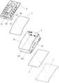
- Figure 2 is an exploded view of a fuel cell with a novel box provided in the first embodiment of the present invention
- Figure 3 is a perspective view of a fuel cell tank according to an embodiment of the invention.
- Figure 4 is a cross-sectional view of the box in the first embodiment of the present invention.
- Fig. 5 is an enlarged view of part A of Fig. 4;
- Figure 6 is an enlarged view of B in Figure 4.
- Figure 7 is an exploded view of the box in the first embodiment of the present invention.
- Figure 8 is a perspective view of the cover plate of the first embodiment of the present invention.
- Figure 9 is an exploded view of the cover plate of the first embodiment of the present invention.
- Embodiment 1 of the present invention is a schematic diagram of the principle of Embodiment 1 of the present invention.
- FIG. 11 is a circuit block diagram of a fuel cell leakage gas detection and control circuit according to an embodiment of the invention.
- Figure 12 is an exploded view of the fuel cell of the second embodiment of the invention.
- FIG. 13 is a schematic diagram of the structure of the bottom plate of the fuel cell in the second embodiment of the present invention.
- Figure 14 is a front view of a fuel cell according to a second embodiment of the invention.
- Figure 15 is a cross-sectional view of C-C in Figure 14;
- Figure 16 is a partial enlarged view of part D in Figure 15;
- Figure 17 is a perspective view of a joint of the third embodiment of the present invention from one angle;
- Figure 19 is a perspective view of the fuel cell of the third embodiment of the present invention.
- Figure 21 is a side view of a fuel cell according to the third embodiment of the present invention.
- Figure 22 is a cross-sectional view taken along line E-E of Figure 21;
- Fig. 23 is a partial enlarged view of part F in Fig. 22.
- this embodiment provides a fuel cell with a new type of box, including a box, a fuel cell module 6 is installed in the box, and the fuel cell module 6 includes a stack module 61,
- the hydrogen circulation pump 62, the air gas path system, the cooling system, the fuel cell control system, and the hydrogen gas path system 63 are characterized in that: the box body includes a bottom plate 1, a box frame 3, and a cover plate 5.
- the fuel cell module 6 Installed on the bottom plate 1, the box frame 3 is formed by connecting side plates 31 end to end.
- the bottom of the box frame 3 is provided with a lower opening 32, the top of the box frame 3 is provided with an upper opening 33, and the box frame 3 has a lower opening 32.
- the cover plate 5 is installed on the box frame 3 and closes the upper opening 33.
- a lower sealing ring 2 is provided between the box frame 3 and the bottom plate 1.
- An upper sealing ring 4 is provided between 3 and the cover plate 5.
- the fuel cell module 6 is first installed on the open bottom plate 1 during production and assembly, and then the box frame 3 is placed outside the fuel cell module 6 and connected
- the relevant interface of the battery module 6 is finally assembled by closing the cover 5, which is easy to assemble;
- the cover 5 and the box frame 3 are sealed by the upper sealing ring 4, and the box frame 3 and the bottom plate 1 are sealed by the bottom Ring 2 is sealed to meet the protection requirements of IP67, and the sealing effect is good;
- the bottom plate 1 and the cover plate 5 can be universally used for fuel cells of different powers.
- the producer only needs to replace the box frame 3 of different heights according to the power density of different fuel cells. This improves the versatility of the outer box and reduces production and design costs.
- the box frame 3 described above is provided with a lower flange 321 outward at the lower opening 32, the lower flange 321 is installed on the bottom plate 1, the lower sealing ring 2 is installed between the lower flange 321 and the bottom plate 1, and the box frame 3 has an upper opening
- An upper flange 331 is provided at 33 outwards, the cover plate 5 is installed on the upper flange 331, and the upper sealing ring 4 is installed between the upper flange 331 and the cover plate 5.
- the arrangement of the upper flange 331 and the lower flange 321 facilitates the installation of the box frame 3 and the cover 5.
- the aforementioned bottom plate 1 has a number of installation blocks 11 protruding outside the box frame 3, and hooks 12 are installed on the installation blocks 11.
- the fuel cell can be hoisted up by the hook 12, which facilitates the installation and transportation of the fuel cell.
- the above-mentioned box frame 3 is provided with a stack cooling liquid connection port 373 connected to the fuel cell module 6, a stack air connection port 371, a hydrogen connection port 372, a power connector 374, a data connector 375 and a fan 36.
- the aforementioned box frame 3 and cover plate 5 are made by sheet metal stamping and forming technology.
- the sheet metal manufacturing process is simple, the processing procedures are few, and the quality reliability is high; the box frame 3 and the cover plate 5 made by the sheet metal stamping process can reduce the overall weight of the fuel cell by about 10%, which reduces the weight of the fuel cell and reduces cost.
- the aforementioned bottom plate 1 is made of aluminum alloy material.
- the bottom plate 1 made of aluminum alloy can provide a strong support structure for the fuel cell module 6 while having the advantage of light weight.
- At least one fan 36 is installed in the box frame 3 described above, and the fan 36 and the air outlet cover 51 are located on opposite sides of the box frame 3. It is more conducive to air circulation in the box.
- the above-mentioned box cover 5 is provided with an exhaust hood 51, the bottom plate 1, the box frame 3 and the cover plate 5 enclose a cavity, the exhaust hood 51 is connected to the cavity, and the exhaust fan 9 is installed in the exhaust hood 51.
- the leaked combustible gas can be discharged more effectively.
- the top of the above-mentioned box cover plate 5 protrudes upwardly from the boss 50.
- the boss 50 forms a gas collecting groove 57.
- the combustible gas concentration sensor 8 is located inside the gas collecting groove 57.
- the exhaust hood 56 is attached to the outside of the gas collecting groove 57 and is connected to the The gas collecting tank 57 is connected.
- the gas collecting tank 57 is located at the highest point of the fuel cell, and a large amount of leaked combustible gas is collected in the gas collecting tank 57, which can discharge the leaked combustible gas more efficiently.
- the above-mentioned combustible gas concentration sensor 8 detects the combustible gas concentration electric signal in the gas collecting tank 57 and transmits it to the fuel cell controller for processing.
- the fuel cell controller shuts down and powers off Stack module 61 and close the hydrogen inlet valve.
- the exhaust hood is arranged on the tank cover, so that the exhaust port is arranged at the highest place of the fuel cell.
- the combustible gas is lighter than air. After leakage, the combustible gas will escape upward and approach the tank cover, which can be more effective The leaked combustible gas can be discharged in time and effectively to improve safety and reliability.
- the above-mentioned box cover 5 includes a cover plate 51, a left side plate 52, a front baffle 53, and a rear baffle 54 are arranged from one side of the cover plate 51, and the left side plate 52, the front baffle 53 and the rear baffle 54 enclose the collection chamber. 56.
- the collecting cavity 56 is located below the air collecting groove 57, the top of the left side plate 52 is provided with an air outlet 521, the air outlet 521 is connected with the air collecting groove 57, and the air exhaust hood 51 is installed at the position of the air outlet 521.
- the structure is simple and easy to manufacture.
- the combustible gas concentration sensor 23 is located in the gas collecting tank 242, which is convenient for accurately detecting the concentration of the leaked combustible gas. It has better safety and reliability, simple structure, convenient installation and easy implementation.
- the above-mentioned exhaust hood 51 is installed at the position of the exhaust port 521 of the left side plate 52 by screws 58 and a sealing ring 59.
- the structure is simple and the sealing is good.
- the aforementioned front baffle 53 and rear baffle 54 have an inclined bottom edge 55 for easy installation.
- this embodiment is an improvement on the basis of the first embodiment and includes a box body.
- the cavity 101 in the box body is equipped with a stack module 61 and a hydrogen circulation pump 62.
- the box body includes a bottom plate. 1.
- the stack module 61 and the hydrogen circulation pump 62 are installed on the bottom plate 1.
- the bottom plate 1 is provided with a leakage hole 121a.
- the leakage hole 121a communicates with the cavity 101 in the box and the outside of the box.
- the leakage hole 121a is close to The outer end of the tank is sealed with a seal 4a. By disassembling the seal 4a, the internal leakage of the fuel cell tank can be detected and drained.
- the structure is simple, and it can effectively prevent the accumulation of liquid in the tank from causing fuel cell failure. run.
- the leakage hole 121a is a bent through hole. One end of the leakage hole 121a is located on the top surface 122a of the bottom plate 1, and the other end of the leakage hole 121a is located on the side surface 123a of the bottom plate 1.
- the seal 4a blocks the leakage hole from the side surface 123a of the bottom plate 1.
- One end of 121a facilitates the discharge of liquid inside the box, and the bent through hole has a certain length to facilitate storage of certain leakage.
- the liquid leakage hole 121a is a right-angle through hole, which facilitates the discharge of liquid inside the box.
- leakage holes 121a which are arranged along the edge of the bottom plate 1 of the box body to facilitate the discharge of liquid inside the box body.
- the sealing member 4a is a sealing plug screw.
- the end of the leakage hole 121a located on the side surface 123a is provided with an internal thread.
- the sealing plug screw is screwed to the end located on the leakage hole 121a near the side surface 123a, which is convenient and quick to install and remove. It is convenient for the staff to regularly check the leakage and discharge.
- a sealing ring 5a is provided between the sealing member 4a and the side surface 123a of the bottom plate 1 to prevent liquid from seeping out.
- the number of the leakage holes 121a is 4, and the leakage holes 121a are located on the two side surfaces 123a of the bottom plate 1, so as to facilitate the discharge of the liquid inside the box.
- a fuel cell includes a box, a stack module 61, and a fuel cell controller.
- the stack module 61 and the fuel cell controller The cooling fluid connector 373 is installed in the cavity 101 of the box body, and the cooling fluid connector 373 is installed on the box body. It is characterized in that: the cooling fluid connector 373 includes a connector body 1b with a through hole 11b in the middle of the connector body 1b. From left to right, it is divided into inner joint 12b, threaded connection section 13b, wrench screw boss 14b and outer joint 15b. It has simple structure, few parts, low manufacturing cost, high sealing reliability, small space occupation and easy installation.
- the above-mentioned threaded connection section 13b is a cone. External threads are machined on the surface of the cone.
- the outer diameter of the part close to the inner joint 12b is smaller, and the outer diameter of the screw boss 14b close to the wrench is larger, which is convenient for installation and has good sealing performance.
- the outer diameter D1 of the above-mentioned wrench screwing boss 14b is larger than the outer diameter D2 of the threaded connecting section 13b, and the outer diameter D2 of the threaded connecting section 13b is larger than the outer diameter D3 of the inner joint 12b, which is convenient for installation.
- the outer diameter D3 of the aforementioned inner joint 12b is equal to the outer diameter D4 of the outer joint 15b.
- the above-mentioned spanner screwing boss 14b has a hexagonal cross-section, which is convenient to cooperate with the spanner and is easy to install.
- the aforementioned joint body 1b is made of hardware materials.
- the above-mentioned stack module 61 is connected to the inner joint 12b through a pipe 103b.
- the boss 14b and the outer joint 15b are screwed by a wrench to protrude outside the box.
- the pipe 103b is a silicone tube, which is convenient for connection and sealing with the inner joint 12b. Simple structure, few parts, low manufacturing cost, high sealing reliability, small space occupation and easy installation.
- the outer joint 15b is used to connect with the pipe of the coolant system outside the box.
- the above-mentioned box body includes a box frame 3 and a cover plate 5 installed on the top of the box frame 3.
- a boss 25b is provided on the side wall of the box frame 3, and a mounting hole 251b is provided on the boss 25b.
- the cavity 101 is connected, and the middle of the joint body 1b is installed in the mounting hole 251b.
- the above-mentioned mounting hole 251b is a tapered hole.
- the inner surface of the tapered hole has internal threads.
- the part of the tapered hole near the cavity 101 has a smaller outer diameter, and the outer diameter near the outside of the box body is larger.
- the threaded connection section 13b and the boss 25b are threadedly connected, the structure is simple, the parts are few, and the manufacturing cost is low.
- threaded connection section 13b is wound with tape 16b on the outside and then screwed into the mounting hole 251b or threaded section 13b is wound with tape 16b on the outside and screwed into the mounting hole 251b after being coated with sealing glue, which can further improve sealing reliability.
- the threaded connection section 13b When installing, the threaded connection section 13b is wrapped with tape 16b and coated with sealing glue. Use a wrench to tighten the wrench to screw the boss 14b, and then turn the wrench to drive the joint body 1b to rotate, so that the threaded connection section 13b and the boss 25b are threadedly connected , Easy installation, few parts, low manufacturing cost, high sealing reliability, and small space occupation.
Landscapes
- Life Sciences & Earth Sciences (AREA)
- Engineering & Computer Science (AREA)
- Manufacturing & Machinery (AREA)
- Sustainable Development (AREA)
- Sustainable Energy (AREA)
- Chemical & Material Sciences (AREA)
- Chemical Kinetics & Catalysis (AREA)
- Electrochemistry (AREA)
- General Chemical & Material Sciences (AREA)
- Fuel Cell (AREA)
Abstract
一种带新型箱体的燃料电池,包括箱体、箱体内安装有电堆模块(61)和燃料电池控制器,所述箱体包括底板(1)、箱框(3)和盖板(5),所述电堆模块(61)安装在底板(1)上,箱框(3)由若干侧板(31)首尾相连接而成,箱框(3)的底部设有下开口(32),箱框(3)的顶部设有上开口(33),箱框(3)的下开口(32)安装在底板(1)上且箱框(3)围在电堆模块(61)外围,盖板(5)安装在箱框(3)上并封闭上开口(33),箱框(3)与底板(1)之间设有下密封圈(2),箱框(3)与盖板(5)之间设有上密封圈(4)。燃料电池组装方便,成本低,箱体通用性强。
Description
本发明涉及一种带新型箱体的燃料电池。
燃料电池是一种电力供应能源装置,目前燃料电池的成组方式结构复杂,燃料电池包括外箱和安装在外箱内的燃料电池模组,燃料电池模组包括电堆模块、氢气循环泵、空气气路系统、冷却系统、燃料电池控制系统和氢气气路系统等,为更好的保护各个模块,外箱多采用以下两种结构组成:一是由半封闭式箱体加盖板组成,箱体包括底面和若干侧面,箱体由压铸工艺制成,但这种外箱的重量重及加工成本高;二是由框架结构加防护罩组成,框架结构框架结构钣金工艺制成,这种外箱的加工工艺复杂且不能满足IP67的防护等级;且这两种外箱都存在组装效率低、通用性差的缺点,致使电池系统装配成组的效率低下,对燃料电池产品在市场上批量的推广应用非常不利。
另外,燃料电池是一种电力供应能源装置,目前燃料电池的成组方式结构复杂,燃料电池包括安装箱和安装在安装箱内的电堆模块、燃料电池控制器、氢气循环泵、进氢阀门件等,由于燃料电池使用氢气或其他可燃气体作为能源原料,在使用过程中会泄露少量的氢气或可燃气体,如果箱体里面积聚过高浓度的氢气或可燃气体很有可能产生爆炸的危险,为此燃料电池在使用过程中有一项非常重要的安全措施,是对燃料电池内部的泄漏的氢气或可燃气体持续有效的排放,使箱体内空气中可燃气体浓度低于爆炸浓度值或许可值,并对其可燃气体的浓度进行实时监测。市场现有的燃料电池产品的排风出口,均设置在箱体侧面,该结构存在不合理的地方:可燃气体比空气轻,泄漏后,可燃气体会往上逃逸,而排风口设置在箱框的侧面并不是燃料电池最高的地方,在最高的地方就会出现堆积可燃气体不能有效排出,因此会存在安全隐患。
第三,现有的燃料电池包括利用电化学反应而发电的电池反应堆,对电池反应堆进行降温的冷却系统、以及对电池反应堆和冷却系统进行控制的燃料电 池系统控制器。电池反应堆包括电池反应堆和抽风装置,抽风装置向电池反应堆送入空气,电池反应堆利用储存在气瓶中的氢气输送过来与被送入的空气中的氧气之间发生电化学反应来产生电能,在此过程中电池反应堆会排出大量的反应副产物——热量和水,其中,热量需冷却系统带走,冷却系统的主要介质为去离子水和防冻液。电池内部有冷却液进出口管道,在装车后,由于强烈震动的存在或者长期运行管路老化等原因,引起管路轻微漏液,长期会积水较多在内部,造成电池失效潜在风险。目前的燃料电池系统是没有漏液防护机制。
第四,目前现有的燃料电池箱体结构,为了满足IP67防护等级要求,电池箱体内外的冷却液进出口都是采用O型圈、螺钉、带法兰面管接头进行密封装配,来满足箱体此处的密封要求。这种结构存在几个问题:因为有O型圈密封区域,螺钉位,占用的空间大;成本较高、因为较多的零件加工与装配;配合面多,对零件的加工与装配控制要求多,可靠性低。
发明内容:
本发明的目的是提供一种燃料电池的外箱及燃料电池,能解决现有外箱组装效率低、通用性差的问题。
本发明的目的是通过下述技术方案予以实现的。
一种带新型箱体的燃料电池,包括箱体、箱体内安装有电堆模块和燃料电池控制器,其特征在于:所述箱体包括底板、箱框和盖板,所述电堆模块安装在底板上,箱框由若干侧板首尾相连接而成,箱框的底部设有下开口,箱框的顶部设有上开口,箱框的下开口安装在底板上且箱框围在电堆模块外围,盖板安装在箱框上并封闭上开口,箱框与底板之间设有下密封圈,箱框与盖板之间设有上密封圈。
上述所述的箱框在下开口处向外设有下翻边,下翻边安装在底板上,下密封圈安装在下翻边与底板之间,箱框在上开口处向外设有上翻边,盖板安装在上翻边上,上密封圈安装在上翻边与盖板之间。
上述的箱盖上设置排风罩,底板、箱框和盖板围成空腔,排风罩与空腔连 通,排风罩里面安装抽风风扇。
上述的箱盖板顶部向上凸出凸台,凸台里面形成集气槽,可燃气体浓度传感器位于集气槽里面,排风罩贴装在集气槽外且与集气槽连通。
上述的可燃气体浓度传感器检测集气槽里面的可燃气体浓度电信号并传送到燃料电池控制器处理,当集气槽里面的可燃气体浓度超过设定值时,燃料电池控制器关停电堆模块和关闭进氢阀门。
上述的箱盖包括盖板、从盖板的一侧设置左侧板、前挡板和后挡板,左侧板、前挡板和后挡板围城收集腔,收集腔位于集气槽下方,左侧板的顶部开有排风口,排风口与集气槽连通,排风罩安装在排风口的位置。
上述的排风罩通过螺钉、密封圈安装在左侧板的排风口的位置。
上述的前挡板和后挡板有一倾斜的底边。
上述所述的底板在箱框外凸出有若干安装块,安装块上安装有吊钩,所述箱框上安装有与燃料电池模组连接的电堆冷却液连接口、电堆空气连接口、氢气连接口、电源接头、数据接头和风扇。
上述所述的箱框和盖板由钣金冲压成型工艺制成,所述底板采用铝合金材质制成。
上述所述的箱框安装有至少一个风扇,风扇与出风罩位于箱框的相对的两侧面上。
上述所述的底板设置有漏液孔,漏液孔连通箱体内的空腔和箱体外部,漏液孔靠近箱体外部的一端用密封件密封。
上述所述的密封件是密封堵头螺钉,漏液孔的位于侧面的一端设置内螺纹,密封堵头螺钉通过螺纹连接在位于漏液孔靠近侧面的一端。
上述的漏液孔有多个,且沿着箱体的底板边缘布局,。
上述所述的密封件是密封堵头螺钉,漏液孔的位于侧面的一端设置内螺纹,密封堵头螺钉通过螺纹连接在位于漏液孔侧面的一端。
上述所述密封件与底板的侧面之间设有密封圈。
上述所述漏液孔是直角通孔。
上述所述的箱体上安装冷却液接头,所述的冷却液接头,包括接头本体,接头本体中间一个贯通孔,接头本体由左至右分为内接头、螺纹连接段、扳手旋拧凸台和外接头。
上述所述的螺纹连接段是圆锥体,圆锥体表面上加工外螺纹,靠近内接头部分的外径较小,靠近扳手旋拧凸台的外径较大。
上述所述的扳手旋拧凸台的外径D1大于螺纹连接段的外径D2,螺纹连接段的外径D2大于内接头的外径D3。
上述的内接头的外径D3等于外接头的外径D4,扳手旋拧凸台的截面是六角形。
本发明与现有技术相比,具有如下效果:
1)燃料电池的外箱包括底板、箱框和盖板,箱框由若干侧板首尾相连接而成,箱框的底部向外设有下翻边,下翻边安装在底板上,下翻边与底板之间设有下密封圈,箱框的顶部向外设有上翻边,盖板安装在上翻边上,上翻边与盖板之间设有上密封圈;外箱分三层式结构,安装简单,燃料电池组装方便;盖板与箱框之间由上密封圈密封,箱框与底板之间由下密封圈密封,密封效果好;外箱的底板和盖板可通用于不同的功率的燃料电池,生产者只需根据不同燃料电池的功率密度更换不同高度的箱框,提高了外箱的通用性,减少了生产成本和设计成本。
2)所述燃料电池,通过对外箱的结构进行改良,在生产组装时,先将燃料电池模组安装在开放的底板上,安装好后再将箱框套在燃料电池模组外并连接燃料电池模组与箱框的相关接头,最后合上盖板即完成组装,组装方便,装配效率高,生产成本低。
3)本发明的其它优点在实施例部分展开详细描述。
图1是本发明实施例一提供的带新型箱体的燃料电池的立体图;
图2是本发明实施例一提供的带新型箱体的燃料电池的爆炸图;
图3是本发明实施例一燃料电池的箱体的立体图;
图4是本发明实施例一的箱体的剖视图;
图5是图4的A处放大图;
图6是图4的B处放大图;
图7是本发明实施例一的箱体的爆炸图;
图8是本发明实施例一的盖板的立体图;
图9是本发明实施例一的盖板的分解图;
图10是本发明实施例一的原理示意图;
图11是发明实施例一燃料电池的泄露燃气检测控制的电路方框图;
图12是发明实施例二的燃料电池的分解图;
图13是本发明实施例二的燃料电池中底板的结构示意图;
图14是发明实施例二的燃料电池的正视图;
图15是图14中C-C的剖视图;
图16是图15中D部分的局部放大图;
图17是本发明实施例三的接头的一个角度的立体图;
图18是本发明实施例三的接头的结构剖视图;
图19是本发明实施例三的燃料电池的立体图
图20是本发明实施例三的燃料电池的分解图;
图21是本发明实施例三的燃料电池的侧视图;
图22是图21的E-E剖视图;
图23是图22的F部分局部放大图。
下面通过具体实施例并结合附图对本发明作进一步详细的描述。
实施例一:
如图1至图11所示,本实施例提供的是一种带新型箱体的燃料电池,包括箱体、箱体内安装有燃料电池模组6,燃料电池模组6包括电堆模块61、氢气循环泵62、空气气路系统、冷却系统、燃料电池控制系统和氢气气路系统63,其特征在于:所述箱体包括底板1、箱框3和盖板5,所述燃料电池模组6安装在底板1上,箱框3由若干侧板31首尾相连接而成,箱框3的底部设有下开口32,箱框3的顶部设有上开口33,箱框3的下开口32安装在底板1上且箱框3围在燃料电池模组6外围,盖板5安装在箱框3上并封闭上开口33,箱框3与底板1之间设有下密封圈2,箱框3与盖板5之间设有上密封圈4。
本实施例所述带新型箱体的燃料电池,在生产组装时先将燃料电池模组6安装在开放的底板1上,安装好后再将箱框3套在燃料电池模组6外并连接然料电池模组6的相关接口,最后合上盖板5即完成组装,组装方便;盖板5与箱框3之间由上密封圈4密封,箱框3与底板1之间由下密封圈2密封,满足IP67的防护要求,密封效果好;底板1和盖板5可通用于不同的功率的燃料电池,生产者只需根据不同燃料电池的功率密度更换不同高度的箱框3,提高了外箱的通用性,减少了生产成本和设计成本。
上述所述箱框3在下开口32处向外设有下翻边321,下翻边321安装在底板1上,下密封圈2安装在下翻边321与底板1之间,箱框3在上开口33处向外设有上翻边331,盖板5安装在上翻边331上,上密封圈4安装在上翻边331与盖板5之间。上翻边331和下翻边321的设置方便了箱框3和盖板5的安装。
上述所述底板1在箱框3外凸出有若干安装块11,安装块11上安装有吊钩12。燃料电池可通过吊钩12吊装起来,吊钩12方便了燃料电池的安装及搬运。
上述所述箱框3上安装有与燃料电池模组6连接的电堆冷却液连接口373、电堆空气连接口371、氢气连接口372、电源接头374、数据接头375和风扇36。
上述所述箱框3和盖板5由钣金冲压成型工艺制成。钣金制造工艺简单,加工工序少,质量可靠性高;钣金冲压成型工艺制成的箱框3和盖板5使燃料电池的整体重量减少10%左右,减轻了燃料电池的重量,降低了成本。
上述所述底板1采用铝合金材质制成。铝合金材质的底板1能为燃料电池模组6提供强大的支撑结构强度,同时有重量轻的优点。
上述所述的箱框3安装有至少一个风扇36,风扇36与出风罩51位于箱框3的相对的两侧面上。更利于箱体内的空气循环。
上述箱盖5上设置排风罩51,底板1、箱框3和盖板5围成空腔,排风罩51与空腔连通,排风罩51里面安装抽风风扇9。可以更有效将泄漏的可燃气体排出。
上述的箱盖板5顶部向上凸出凸台50,凸台50里面形成集气槽57,可燃气体浓度传感器8位于集气槽57里面,排风罩56贴装在集气槽57外且与集气槽57连通。集气槽57位于燃料电池最高的地方,大量的泄漏的可燃气体汇聚到集气槽57,可以更高效将泄漏的可燃气体排出。
上述的可燃气体浓度传感器8检测集气槽57里面的可燃气体浓度电信号并传送到燃料电池控制器处理,当集气槽57里面的可燃气体浓度超过设定值时,燃料电池控制器关停电堆模块61和关闭进氢阀门。本发明的燃料电池将排风罩设置在箱盖上,使排风口设置在燃料电池最高的地方,可燃气体比空气轻,泄漏后,可燃气体会往上逃逸靠近箱盖,这样可以更加有效将泄漏的可燃气体能及时有效排出,提高安全性和可靠性。
上述的箱盖5包括盖板51、从盖板51的一侧设置左侧板52、前挡板53和后挡板54,左侧板52、前挡板53和后挡板54围城收集腔56,收集腔56位于集气槽57下方,左侧板52的顶部开有排风口521,排风口521与集气槽57连通,排风罩51安装在排风口521的位置。结构简单,制造容易,可燃气体浓度传感器23位于集气槽242里面,方便准确检测泄漏的可燃气体浓度。安全可靠性更好,结构简单,安装方便,实施容易。
上述的排风罩51通过螺钉58、密封圈59安装在左侧板52的排风口521的位置。结构简单,密封性好。
上述的前挡板53和后挡板54有一倾斜的底边55,便于安装。
实施例二:
如图12至图16所示,本实施例是实施例一基础上的改良,包括箱体,箱体内的空腔101安装有电堆模组61和氢气循环泵62,所述箱体包括底板1,电堆模组61和氢气循环泵62安装在底板1上,所述底板1设置有漏液孔121a,漏液孔121a连通箱体内的空腔101和箱体外部,漏液孔121a靠近箱体外部的一端用密封件4a密封,通过拆卸密封件4a,可以对燃料电池箱体内部漏液情况进行检测和排液工作,结构简单,有效防止液体积累在箱体内部导致燃料电池失效停止运行。
漏液孔121a是折弯通孔,漏液孔121a的一端位于底板1顶面122a,漏液孔121a的另一端位于底板1的侧面123a,密封件4a从底板1侧面123a封堵漏液孔121a的一端,便于箱体内部的液体排出,折弯通孔具有一定的长度,便于储存一定的漏液。
所述漏液孔121a是直角通孔,便于箱体内部的液体排出。
漏液孔121a有多个,且沿着箱体的底板1边缘布局,便于箱体内部的液体排出。
所述密封件4a是密封堵头螺钉,漏液孔121a的位于侧面123a的一端设置内螺纹,密封堵头螺钉通过螺纹连接在位于漏液孔121a靠近侧面123a的一端,安装和拆卸方便快捷,便于工作人员定期检测漏液情况和排液。
所述密封件4a与底板1的侧面123a之间设有密封圈5a,密封效果,防止液体渗出。
所述漏液孔121a数量为4个,且两两位于底板1的两侧面123a,便于箱体内部的液体排出。
实施例三:
如图17至图23所示,本实施例是在实施例一基础上的改进:一种燃料电 池,包括箱体、电堆模块61、燃料电池控制器,其中电堆模块61、燃料电池控制器安装在箱体的空腔101里面,在箱体上安装冷却液接头373,其特征在于:所述的冷却液接头373包括接头本体1b,接头本体1b中间一个贯通孔11b,接头本体1b由左至右分为内接头12b、螺纹连接段13b、扳手旋拧凸台14b和外接头15b,结构简单,零件少,制造成本低,密封可靠性高,占用空间小,安装简便。
上述的螺纹连接段13b是圆锥体,圆锥体表面上加工外螺纹,靠近内接头12b部分的外径较小,靠近扳手旋拧凸台14b的外径较大,便于安装,安装密封性好。
上述扳手旋拧凸台14b的外径D1大于螺纹连接段13b的外径D2,螺纹连接段13b的外径D2大于内接头12b的外径D3,便于安装。
上述的内接头12b的外径D3等于外接头15b的外径D4。
上述的扳手旋拧凸台14b的截面是六角形,方便与扳手配合,安装方便。
上述所述的接头本体1b是五金材料制造。
上述的电堆模块61通过管道103b连接内接头12b,扳手旋拧凸台14b和外接头15b凸出箱体外部,管道103b是硅胶管,方便与内接头12b连接密封。结构简单,零件少,制造成本低,密封可靠性高,占用空间小,安装简便。外接头15b用于与箱体外部的冷却液系统的的管道连接。
上述的所述的箱体包括箱框3和安装在箱框3顶端的盖板5,箱框3的侧壁上设置有凸台25b,凸台25b上设置安装孔251b,安装孔251b与空腔101连通,接头本体1b的中部安装在安装孔251b里面。
上述的安装孔251b是圆锥孔,圆锥孔的内表面加工内螺纹,圆锥孔靠近空腔101的部分外径较小,靠近箱体外部的外径较大,螺纹连接段13b旋进安装孔251b,螺纹连接段13b与凸台25b螺纹连接起来,结构简单,零件少,制造成本低。
上述的螺纹连接段13b外表缠绕胶带16b后旋进安装孔251b或者螺纹连接 段13b外表缠绕胶带16b和涂上密封胶水后旋进安装孔251b,可以进一步提供密封可靠性。
安装时,螺纹连接段13b外表缠绕胶带16b和涂上密封胶水,利用扳手套紧在扳手旋拧凸台14b,然后转动扳手带动接头本体1b转动,使螺纹连接段13b与凸台25b螺纹连接起来,安装简便,零件少,制造成本低,密封可靠性高,占用空间小。
以上实施例为本发明的较佳实施方式,但本发明的实施方式不限于此,其他任何未背离本发明的精神实质与原理下所作的改变、修饰、替代、组合、简化,均为等效的置换方式,都包含在本发明的保护范围之内。
Claims (21)
- 一种带新型箱体的燃料电池,包括箱体、箱体内安装有电堆模块(61)和燃料电池控制器,其特征在于:所述箱体包括底板(1)、箱框(3)和盖板(5),所述电堆模块(61)安装在底板(1)上,箱框(3)由若干侧板(31)首尾相连接而成,箱框(3)的底部设有下开口(32),箱框(3)的顶部设有上开口(33),箱框(3)的下开口(32)安装在底板(1)上且箱框(3)围在电堆模块(61)外围,盖板(5)安装在箱框(3)上并封闭上开口(33),箱框(3)与底板(1)之间设有下密封圈(2),箱框(3)与盖板(5)之间设有上密封圈(4)。
- 根据权利要求1所述的一种带新型箱体的燃料电池,其特征在于:所述箱框(3)在下开口(32)处向外设有下翻边(321),下翻边(321)安装在底板(1)上,下密封圈(2)安装在下翻边(321)与底板(1)之间,箱框(3)在上开口(33)处向外设有上翻边(331),盖板(5)安装在上翻边(331)上,上密封圈(4)安装在上翻边(331)与盖板(5)之间。
- 根据权利要求1或2所述的一种带新型箱体的燃料电池,其特征在于:箱盖(5)上设置排风罩(51),底板(1)、箱框(3)和盖板(5)围成空腔,排风罩(51)与空腔连通,排风罩(51)里面安装抽风风扇(9)。
- 根据权利要求3所述的一种带新型箱体的燃料电池,其特征在于:箱盖板(5)顶部向上凸出凸台(50),凸台(50)里面形成集气槽(57),可燃气体浓度传感器(8)位于集气槽(57)里面,排风罩(56)贴装在集气槽(57)外且与集气槽(57)连通。
- 根据权利要求4所述的一种带新型箱体的燃料电池,其特征在于:可燃气体浓度传感器(8)检测集气槽(57)里面的可燃气体浓度电信号并传送到燃料电池控制器处理,当集气槽(57)里面的可燃气体浓度超过设定值时,燃料电池控制器关停电堆模块(61)和关闭进氢阀门。
- 根据权利要求5所述的一种带新型箱体的燃料电池,其特征在于:箱盖(5)包括盖板(51)、从盖板(51)的一侧设置左侧板(52)、前挡板(53)和 后挡板(54),左侧板(52)、前挡板(53)和后挡板(54)围城收集腔(56),收集腔(56)位于集气槽(57)下方,左侧板(52)的顶部开有排风口(521),排风口(521)与集气槽(57)连通,排风罩(51)安装在排风口(521)的位置。
- 根据权利要求6所述的一种使用新型安装箱的燃料电池,其特征在于:排风罩(51)通过螺钉(58)、密封圈(59)安装在左侧板(52)的排风口(521)的位置。
- 根据权利要求7所述的一种使用新型安装箱的燃料电池,其特征在于:前挡板(53)和后挡板(54)有一倾斜的底边(55)。
- 根据权利要求6所述的一种带新型箱体的燃料电池,其特征在于:所述底板(1)在箱框(3)外凸出有若干安装块(11),安装块(11)上安装有吊钩(12),所述箱框(3)上安装有与燃料电池模组(6)连接的电堆冷却液连接口(373)、电堆空气连接口(371)、氢气连接口(372)、电源接头(374)、数据接头(375)和风扇(36)。
- 根据权利要求9所述的一种带新型箱体的燃料电池,其特征在于:所述箱框(3)和盖板(5)由钣金冲压成型工艺制成,所述底板(1)采用铝合金材质制成。
- 根据权利要求10所述的一种带新型箱体的燃料电池,其特征在于:所述箱框(3)安装有至少一个风扇(36),风扇(36)与出风罩(51)位于箱框(3)的相对的两侧面上。
- 根据权利要求1或2所述的一种带新型箱体的燃料电池,其特征在于:所述底板(1)设置有漏液孔(121a),漏液孔(121a)连通箱体内的空腔(101)和箱体外部,漏液孔(121a)靠近箱体外部的一端用密封件(4a)密封。
- 根据权利要求12所述的一种带新型箱体的燃料电池,其特征在于:漏液孔(121a)是折弯通孔,漏液孔(121a)的一端位于底板(1)的顶面(122a),漏液孔(121a)的另一端位于底板(1)的侧面(123a),密封件(4a)从底板(1)侧面(123a)封堵漏液孔(121a)的一端。
- 根据权利要求13所述的一种带新型箱体的燃料电池,其特征在于:漏液孔(121a)有多个,且沿着箱体的底板(1)边缘布局,。
- 根据权利要求14所述的一种带新型箱体的燃料电池,其特征在于:所述密封件(4a)是密封堵头螺钉,漏液孔(121a)的位于侧面(123a)的一端设置内螺纹,密封堵头螺钉通过螺纹连接在位于漏液孔(121a)靠近侧面(123a)的一端。
- 根据权利要求15所述的一种带新型箱体的燃料电池,其特征在于:所述密封件(4a)与底板(1)的侧面(123a)之间设有密封圈(5a)。
- 根据权利要求16所述的一种带新型箱体的燃料电池,其特征在于:所述漏液孔(121a)是直角通孔。
- 根据权利要求1或2所述的一种带新型箱体的燃料电池,其特征在于:箱体上安装冷却液接头(373),所述的冷却液接头(373),包括接头本体(1b),接头本体(1b)中间一个贯通孔(11b),接头本体(1b)由左至右分为内接头(12b)、螺纹连接段(13b)、扳手旋拧凸台(14b)和外接头(15b)。
- 根据权利要求18所述的一种带新型箱体的燃料电池,其特征在于:螺纹连接段(13b)是圆锥体,圆锥体表面上加工外螺纹,靠近内接头(12b)部分的外径较小,靠近扳手旋拧凸台(14b)的外径较大。
- 根据权利要求19所述的一种带新型箱体的燃料电池,其特征在于:扳手旋拧凸台(14b)的外径D1大于螺纹连接段(13b)的外径D2,螺纹连接段(13b)的外径D2大于内接头(12b)的外径D3。
- 根据权利要求20所述的一种带新型箱体的燃料电池,其特征在于:内接头(12b)的外径D3等于外接头(15b)的外径D4,扳手旋拧凸台(14b)的截面是六角形。
Applications Claiming Priority (14)
| Application Number | Priority Date | Filing Date | Title |
|---|---|---|---|
| CN201920255007.6U CN209312926U (zh) | 2019-02-28 | 2019-02-28 | 一种带新型箱体的燃料电池 |
| CN201910151098.3 | 2019-02-28 | ||
| CN201920255032.4U CN209418674U (zh) | 2019-02-28 | 2019-02-28 | 一种使用新型安装箱的燃料电池 |
| CN201910151033.9A CN109830733B (zh) | 2019-02-28 | 2019-02-28 | 一种带新型箱体的燃料电池 |
| CN201920255006.1U CN209312925U (zh) | 2019-02-28 | 2019-02-28 | 一种带漏液防护的燃料电池 |
| CN201920255006.1 | 2019-02-28 | ||
| CN201910151033.9 | 2019-02-28 | ||
| CN201920255664.0 | 2019-02-28 | ||
| CN201920255032.4 | 2019-02-28 | ||
| CN201910151760.5A CN109707925B (zh) | 2019-02-28 | 2019-02-28 | 一种用于管道连接的接头及燃料电池 |
| CN201920255664.0U CN209688288U (zh) | 2019-02-28 | 2019-02-28 | 一种用于管道连接的接头及燃料电池 |
| CN201910151760.5 | 2019-02-28 | ||
| CN201910151098.3A CN109728334A (zh) | 2019-02-28 | 2019-02-28 | 一种使用新型安装箱的燃料电池 |
| CN201920255007.6 | 2019-02-28 |
Publications (1)
| Publication Number | Publication Date |
|---|---|
| WO2020173077A1 true WO2020173077A1 (zh) | 2020-09-03 |
Family
ID=72238954
Family Applications (1)
| Application Number | Title | Priority Date | Filing Date |
|---|---|---|---|
| PCT/CN2019/105377 Ceased WO2020173077A1 (zh) | 2019-02-28 | 2019-09-11 | 一种带新型箱体的燃料电池 |
Country Status (1)
| Country | Link |
|---|---|
| WO (1) | WO2020173077A1 (zh) |
Citations (8)
| Publication number | Priority date | Publication date | Assignee | Title |
|---|---|---|---|---|
| US20030235727A1 (en) * | 2002-06-24 | 2003-12-25 | Noetzel John G. | Solid-oxide fuel cell assembly having an electronic control unit within a structural enclosure |
| CN1866582A (zh) * | 2005-05-20 | 2006-11-22 | 上海神力科技有限公司 | 一种燃料电池电堆的封装装置 |
| CN106935892A (zh) * | 2015-12-10 | 2017-07-07 | 本田技研工业株式会社 | 燃料电池系统 |
| CN109707925A (zh) * | 2019-02-28 | 2019-05-03 | 中山大洋电机股份有限公司 | 一种用于管道连接的接头及燃料电池 |
| CN109728334A (zh) * | 2019-02-28 | 2019-05-07 | 中山大洋电机股份有限公司 | 一种使用新型安装箱的燃料电池 |
| CN109830733A (zh) * | 2019-02-28 | 2019-05-31 | 中山大洋电机股份有限公司 | 一种带新型箱体的燃料电池 |
| CN209312926U (zh) * | 2019-02-28 | 2019-08-27 | 中山大洋电机股份有限公司 | 一种带新型箱体的燃料电池 |
| CN209312925U (zh) * | 2019-02-28 | 2019-08-27 | 中山大洋电机股份有限公司 | 一种带漏液防护的燃料电池 |
-
2019
- 2019-09-11 WO PCT/CN2019/105377 patent/WO2020173077A1/zh not_active Ceased
Patent Citations (8)
| Publication number | Priority date | Publication date | Assignee | Title |
|---|---|---|---|---|
| US20030235727A1 (en) * | 2002-06-24 | 2003-12-25 | Noetzel John G. | Solid-oxide fuel cell assembly having an electronic control unit within a structural enclosure |
| CN1866582A (zh) * | 2005-05-20 | 2006-11-22 | 上海神力科技有限公司 | 一种燃料电池电堆的封装装置 |
| CN106935892A (zh) * | 2015-12-10 | 2017-07-07 | 本田技研工业株式会社 | 燃料电池系统 |
| CN109707925A (zh) * | 2019-02-28 | 2019-05-03 | 中山大洋电机股份有限公司 | 一种用于管道连接的接头及燃料电池 |
| CN109728334A (zh) * | 2019-02-28 | 2019-05-07 | 中山大洋电机股份有限公司 | 一种使用新型安装箱的燃料电池 |
| CN109830733A (zh) * | 2019-02-28 | 2019-05-31 | 中山大洋电机股份有限公司 | 一种带新型箱体的燃料电池 |
| CN209312926U (zh) * | 2019-02-28 | 2019-08-27 | 中山大洋电机股份有限公司 | 一种带新型箱体的燃料电池 |
| CN209312925U (zh) * | 2019-02-28 | 2019-08-27 | 中山大洋电机股份有限公司 | 一种带漏液防护的燃料电池 |
Similar Documents
| Publication | Publication Date | Title |
|---|---|---|
| US20100206721A1 (en) | On demand hydrogen enhancement system for internal and external combustion engine | |
| CN110187278B (zh) | 一种电池模组实验箱装置 | |
| WO2022116908A1 (zh) | 高能量锂电池及包括该锂电池的大型储能系统 | |
| CN213071216U (zh) | 一种新能源汽车用电池散热装置 | |
| CN206602729U (zh) | 纯电动物流车用的电机控制器箱体 | |
| CN106793698B (zh) | 风力发电机组密闭式冷却系统 | |
| CN210802824U (zh) | 一种板式换热器漏液报警装置 | |
| CN109707925B (zh) | 一种用于管道连接的接头及燃料电池 | |
| CN209561549U (zh) | 一种燃料电池电堆壳体结构 | |
| WO2020173077A1 (zh) | 一种带新型箱体的燃料电池 | |
| CN209045713U (zh) | 一种带有热管理系统的新能源汽车动力电池模组 | |
| WO2023036248A1 (zh) | 一种用于大型储能系统的电池罐及泄爆方法 | |
| CN109548382B (zh) | 一种高效散热的油田专用变频控制柜 | |
| CN204067518U (zh) | 带有散热装置的电池模块 | |
| CN114614180A (zh) | 一种用于大型储能系统的电池罐 | |
| CN210737698U (zh) | 一种立式隔膜气压罐 | |
| CN104696266A (zh) | 一种液态金属池式驱动装置密封组件 | |
| CN209843764U (zh) | 承压电池结构 | |
| CN215489993U (zh) | 一种具有防腐功能的铸铁散热器 | |
| CN219219216U (zh) | 一种柜式一体化供水设备 | |
| CN218123548U (zh) | 一种被动式电芯灭火系统 | |
| CN217062254U (zh) | 一种锂电池储能柜自动防护系统 | |
| CN118281405A (zh) | 一种水下储能装置 | |
| CN202585678U (zh) | 一种具有散热功能的动力电池及其散热装置 | |
| CN213711244U (zh) | 一种水冷系统用自动补水稳压装置 |
Legal Events
| Date | Code | Title | Description |
|---|---|---|---|
| 121 | Ep: the epo has been informed by wipo that ep was designated in this application |
Ref document number: 19916827 Country of ref document: EP Kind code of ref document: A1 |
|
| NENP | Non-entry into the national phase |
Ref country code: DE |
|
| 122 | Ep: pct application non-entry in european phase |
Ref document number: 19916827 Country of ref document: EP Kind code of ref document: A1 |